WO2021133145A1 - 수술용 연속체 로봇팔 - Google Patents
수술용 연속체 로봇팔 Download PDFInfo
- Publication number
- WO2021133145A1 WO2021133145A1 PCT/KR2020/019230 KR2020019230W WO2021133145A1 WO 2021133145 A1 WO2021133145 A1 WO 2021133145A1 KR 2020019230 W KR2020019230 W KR 2020019230W WO 2021133145 A1 WO2021133145 A1 WO 2021133145A1
- Authority
- WO
- WIPO (PCT)
- Prior art keywords
- continuum
- robot arm
- wire
- cross guide
- continuums
- Prior art date
Links
Images


Classifications
-
- A—HUMAN NECESSITIES
- A61—MEDICAL OR VETERINARY SCIENCE; HYGIENE
- A61B—DIAGNOSIS; SURGERY; IDENTIFICATION
- A61B34/00—Computer-aided surgery; Manipulators or robots specially adapted for use in surgery
- A61B34/70—Manipulators specially adapted for use in surgery
- A61B34/71—Manipulators operated by drive cable mechanisms
-
- A—HUMAN NECESSITIES
- A61—MEDICAL OR VETERINARY SCIENCE; HYGIENE
- A61B—DIAGNOSIS; SURGERY; IDENTIFICATION
- A61B17/00—Surgical instruments, devices or methods, e.g. tourniquets
-
- A—HUMAN NECESSITIES
- A61—MEDICAL OR VETERINARY SCIENCE; HYGIENE
- A61B—DIAGNOSIS; SURGERY; IDENTIFICATION
- A61B17/00—Surgical instruments, devices or methods, e.g. tourniquets
- A61B17/00234—Surgical instruments, devices or methods, e.g. tourniquets for minimally invasive surgery
-
- A—HUMAN NECESSITIES
- A61—MEDICAL OR VETERINARY SCIENCE; HYGIENE
- A61B—DIAGNOSIS; SURGERY; IDENTIFICATION
- A61B17/00—Surgical instruments, devices or methods, e.g. tourniquets
- A61B17/28—Surgical forceps
- A61B17/29—Forceps for use in minimally invasive surgery
-
- A—HUMAN NECESSITIES
- A61—MEDICAL OR VETERINARY SCIENCE; HYGIENE
- A61B—DIAGNOSIS; SURGERY; IDENTIFICATION
- A61B34/00—Computer-aided surgery; Manipulators or robots specially adapted for use in surgery
-
- A—HUMAN NECESSITIES
- A61—MEDICAL OR VETERINARY SCIENCE; HYGIENE
- A61B—DIAGNOSIS; SURGERY; IDENTIFICATION
- A61B34/00—Computer-aided surgery; Manipulators or robots specially adapted for use in surgery
- A61B34/30—Surgical robots
-
- B—PERFORMING OPERATIONS; TRANSPORTING
- B25—HAND TOOLS; PORTABLE POWER-DRIVEN TOOLS; MANIPULATORS
- B25J—MANIPULATORS; CHAMBERS PROVIDED WITH MANIPULATION DEVICES
- B25J9/00—Programme-controlled manipulators
- B25J9/06—Programme-controlled manipulators characterised by multi-articulated arms
-
- B—PERFORMING OPERATIONS; TRANSPORTING
- B25—HAND TOOLS; PORTABLE POWER-DRIVEN TOOLS; MANIPULATORS
- B25J—MANIPULATORS; CHAMBERS PROVIDED WITH MANIPULATION DEVICES
- B25J9/00—Programme-controlled manipulators
- B25J9/16—Programme controls
-
- B—PERFORMING OPERATIONS; TRANSPORTING
- B25—HAND TOOLS; PORTABLE POWER-DRIVEN TOOLS; MANIPULATORS
- B25J—MANIPULATORS; CHAMBERS PROVIDED WITH MANIPULATION DEVICES
- B25J9/00—Programme-controlled manipulators
- B25J9/16—Programme controls
- B25J9/1679—Programme controls characterised by the tasks executed
- B25J9/1689—Teleoperation
-
- A—HUMAN NECESSITIES
- A61—MEDICAL OR VETERINARY SCIENCE; HYGIENE
- A61B—DIAGNOSIS; SURGERY; IDENTIFICATION
- A61B17/00—Surgical instruments, devices or methods, e.g. tourniquets
- A61B17/00234—Surgical instruments, devices or methods, e.g. tourniquets for minimally invasive surgery
- A61B2017/00292—Surgical instruments, devices or methods, e.g. tourniquets for minimally invasive surgery mounted on or guided by flexible, e.g. catheter-like, means
- A61B2017/00296—Surgical instruments, devices or methods, e.g. tourniquets for minimally invasive surgery mounted on or guided by flexible, e.g. catheter-like, means mounted on an endoscope
-
- A—HUMAN NECESSITIES
- A61—MEDICAL OR VETERINARY SCIENCE; HYGIENE
- A61B—DIAGNOSIS; SURGERY; IDENTIFICATION
- A61B17/00—Surgical instruments, devices or methods, e.g. tourniquets
- A61B17/00234—Surgical instruments, devices or methods, e.g. tourniquets for minimally invasive surgery
- A61B2017/00292—Surgical instruments, devices or methods, e.g. tourniquets for minimally invasive surgery mounted on or guided by flexible, e.g. catheter-like, means
- A61B2017/003—Steerable
- A61B2017/00305—Constructional details of the flexible means
- A61B2017/00314—Separate linked members
-
- A—HUMAN NECESSITIES
- A61—MEDICAL OR VETERINARY SCIENCE; HYGIENE
- A61B—DIAGNOSIS; SURGERY; IDENTIFICATION
- A61B17/00—Surgical instruments, devices or methods, e.g. tourniquets
- A61B17/00234—Surgical instruments, devices or methods, e.g. tourniquets for minimally invasive surgery
- A61B2017/00292—Surgical instruments, devices or methods, e.g. tourniquets for minimally invasive surgery mounted on or guided by flexible, e.g. catheter-like, means
- A61B2017/003—Steerable
- A61B2017/00318—Steering mechanisms
- A61B2017/00323—Cables or rods
-
- A—HUMAN NECESSITIES
- A61—MEDICAL OR VETERINARY SCIENCE; HYGIENE
- A61B—DIAGNOSIS; SURGERY; IDENTIFICATION
- A61B17/00—Surgical instruments, devices or methods, e.g. tourniquets
- A61B17/28—Surgical forceps
- A61B17/29—Forceps for use in minimally invasive surgery
- A61B2017/2901—Details of shaft
- A61B2017/2908—Multiple segments connected by articulations
-
- A—HUMAN NECESSITIES
- A61—MEDICAL OR VETERINARY SCIENCE; HYGIENE
- A61B—DIAGNOSIS; SURGERY; IDENTIFICATION
- A61B34/00—Computer-aided surgery; Manipulators or robots specially adapted for use in surgery
- A61B34/30—Surgical robots
- A61B2034/305—Details of wrist mechanisms at distal ends of robotic arms
- A61B2034/306—Wrists with multiple vertebrae
Definitions
- the present invention relates to an endoscopic surgical instrument for the digestive tract, and more particularly, a continuum mechanism is applied, an instrument designed to be embedded and detachable from a cage, and a C-shaped or S-shaped movement can be implemented without dividing a separate section. It is about a continuum robot arm.
- Endoscopic surgery minimizes incision and pain, and has the effect of shortening the hospital stay.
- endoscopic surgery there is a problem in that the partially incised mucous membrane falls down and obstructs the view of the endoscope in the process of incising the mucous membrane. For this reason, the difficulty of endoscopic surgery is high and it is only performed by skilled surgeons.
- an endoscopic surgical robot can be introduced so that even inexperienced surgeons can perform endoscopic surgery, which can dramatically reduce the difficulty of surgery.
- NOTES Natural Orifice Transluminal Endoscopic Surgery
- a surgical tool for endoscopic surgery has a diameter of about 5 mm and a length of about 1 m depending on the insertion passage. And, when the same function can be performed, the smaller the diameter, the more preferable.
- the position of the actuator (motor, etc.) is inevitably located on the outside, and the external actuator is mainly used inside the transmission using a transmission such as a wire rope or a long link. Transmits power to the drive joint.
- the long and thin shaft does not need to be bent, whereas in endoscopic surgery, the shaft must have overall flexibility, and it is preferable to have rigidity in order to exert sufficient force necessary for work or to take a desired posture. .
- the prior art has a problem in that there is a risk of applying an impact to the outer wall of the intestine when the operation of the forceps part is unstable due to the C-shaped movement up and down.
- the present invention includes: a plurality of continuums arranged side by side in the front-rear direction, the upper and lower portions of which are formed with through-holes through which the wire can pass; It is disposed in any one continuum of the plurality of continuums, and a through hole is formed in the upper and lower portions to allow a wire to pass therethrough, and the wire passing through the upper or lower through hole is crossed to the opposite lower portion or upper portion.
- a cross guide formed with a cross through hole to exit; After passing through the upper through-holes of the plurality of continuums adjacent to the rear continuum among the plurality of continuums, passing through the intersecting through-holes of the cross guide, and sequentially passing through the lower through-holes of the adjacent plurality of continuums, the front a first wire having an end fixed to the continuum; and a second wire having an end fixed to the front continuum by passing through the cross guide from the lower through-hole of the rear continuum in a manner corresponding to the first wire; may include.
- the robot arm is installed to be able to move forward and backward in and out of the cage and may be operated in a C-shape or S-shape depending on the length exposed to the outside.
- the cage may be installed on the outer wall of the cylindrical endoscope and movably installed along the outer wall in an arc direction.
- the cage may be formed integrally with the cylindrical endoscope or may be formed detachably from the cylindrical endoscope.
- the front and rear surfaces of the plurality of continuums and the cross guides may be formed in an arc shape so that upper and lower ends of the plurality of continuums or cross guides can be in close contact with each other or spread apart.
- the plurality of continuum and the cross guide include a body having through holes formed therein, and links are formed on the left and right sides of the body in the front and rear directions, respectively, and the links are rotatable to the links of the continuum or cross guide adjacent to the front and rear.
- the plurality of continuum and the cross guide include a body having through-holes formed therein, and the body is connected in a spaced apart state by a connecting part connecting the body of the front and rear continuum or the cross guide, and the bodies and the connecting part All of them are integrally formed, and may be made of a flexible material.
- a gripper capable of biting and catching a target may be connected to the frontmost continuum among the plurality of continuums.
- the gripper is configured such that one end of the first member and the second member is rotatably connected to each other, and the free end, which is the other end, is opened or closed to catch the target, and the first member of the gripper is on a continuum in front.
- a rear end is fixed, and a third wire and a fourth wire passing through the plurality of continuums and the cross guide are respectively connected to the left and right sides of the second member of the gripper, and as the third wire and the fourth wire are pulled, the The second member may be opened or closed with respect to the first member.
- left and right through-holes through which the wires pass may be formed on the left and right sides of the plurality of continuum and the cross guide.
- a left through-hole and a right through-hole are formed in the plurality of continuums and the cross guide with a horizontal center, and a flexible tube-shaped sheath passes through the left through-hole and the right through-hole to pass through the front continuum. It is connected to the continuum at the rear, but a wire passes through the inside of the sheath and can be connected to the gripper.
- the present invention provides the effect of realizing the C-shaped as well as the S-shaped movement and the operation of the gripper or cutter by adjusting the wire passing through the continuum up, down, left and right.
- the robot arm can implement two motions of a C-shape or an S-shape with only a pair of wires.
- the robot arm is embedded inside the cage attached to the endoscope so that it is not exposed to the outside, and when approaching the target lesion, the robot arm advances from the cage to be exposed and work. As it is constructed, there is no fear of damaging nearby organs when moving the endoscope.
- the robot arm since the robot arm has a structure that can be attached and detached to the existing endoscope together with the cage, it can be widely applied to existing commercial endoscopes. According to the present invention, the robot arm rolls motion along the circumferential direction of the endoscope together with the cage. Because it is rotatable in this way, the robot arm can perform tasks in various positions.
- FIG. 1 and 2 are perspective views of an endoscope equipped with a continuum robot arm for surgery according to a first embodiment of the present invention, and shows before and after advancing of the robot arm.
- 3 and 4 are schematic diagrams for the continuum robotic arm for surgery according to the first embodiment of the present invention to proceed with an S-shaped operation, and shows before and after operation of the advanced state.
- 5 and 6 are schematic views for the operation of the continuum robot arm for surgery according to the first embodiment of the present invention to proceed with a C-shaped operation, and shows before and after operation of the advanced state.
- FIG. 7 is a perspective view of a continuum robot arm for surgery according to a second embodiment of the present invention.
- FIG. 8 is a schematic diagram of the operation of the surgical continuum robot arm according to the second embodiment of the present invention.
- FIG. 9 is a perspective view of a continuum robot arm for surgery according to a third embodiment of the present invention.
- FIG. 10 is a schematic diagram of the operation of the surgical continuum robot arm according to the third embodiment of the present invention.
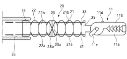
- the surgical continuum robot arm 10 according to the first embodiment of the present invention, with reference to FIGS. 1 to 6 , a plurality of continuum 20, a cross guide 23, a first wire 31, and a second It includes two wires (32).
- the plurality of continuum 20 is, with reference to FIGS. 1 to 6, the upper and lower ends are rotatably arranged side by side with respect to the horizontal center in the front and rear directions, and the wires 31 and 32 pass through the upper and lower ends.
- Through-holes 21a and 22a may be formed.
- the robot arm 10 is, with reference to FIGS. 1 to 6 , the cage 3 is installed to move forward and backward in and out of the cage 3 and may be operated in a C-shape or S-shape depending on the length exposed to the outside.
- the robot arm 10 is installed inside the cage 3 installed on the outer surface 2 of the endoscope to penetrate into the body together with the existing endoscope 1 .
- the robot arm 10 can be operated while being deformed into a C-shape or S-shape by pulling the wires 31 and 32 depending on how far out of the cage 3 is. Therefore, the robot arm can implement two types of motions of a C-shape or an S-shape using only a pair of wires.
- the cage 3 may be installed on the outer wall 2 of the cylindrical endoscope 1 and movably installed along the outer wall 2 in an arc direction. 1 and 2, in the drawing, the cage (3) is located on the upper side of the endoscope (1), but up to a certain angle along the outer diameter of the endoscope (1) Here, up to about 120 degrees in both directions Ride the outer wall (2) rotation is possible. Therefore, by changing the position of the cage 3 as needed to operate the robot arm 10, it is possible to take various positions and postures. That is, since the robot arm 10 can rotate in a roll motion method along the circumferential direction of the endoscope 1 together with the cage 3 , the robot arm 10 can perform tasks in various positions.
- the tunnel 3a formed in the cage 3 so that the robot arm 10 moves forward and backward is formed in a rectangular shape in cross section, and in particular, the robot arm 10 is formed to the extent that it almost touches the wall surface of the tunnel 3a. It is possible to bring about a change in the C-shape and S-shape of the robot arm 10 by the structure of the tunnel 3a. Therefore, the robot arm 10 is embedded in the cage 3 attached to the endoscope 1 until it approaches the target lesion so that it is not exposed to the outside, and when the robot arm 10 approaches the target lesion, the cage (3) is configured so that exposure and work can be progressed from (3), so there is no fear of damaging nearby organs when moving the endoscope (1).
- the cage 3 may be detachable or integrally formed on the outer surface of the endoscope. Therefore, since the robot arm 10 is a structure detachable to the existing endoscope 1 together with the cage 3, it can be widely applied to the existing commercial endoscope.
- the plurality of continuum 20 with reference to FIGS. 2 to 6, the front and rear surfaces are formed in an arc shape so that the upper and lower ends can be in close contact with each other or open with respect to the adjacent continuum 20 or the cross guide 23.
- the adjacent ones and the thickest part of the center are in close contact with each other, and when a force is applied by the wires 31 and 32, the lower part is in close contact when the upper part is opened according to the direction of the applied force.
- the lower part is opened, the upper part is brought into close contact, so that the continuum 20 is changed from a linear arrangement to a curved arrangement.
- the upper and lower ends of the continuum 20 form a plane so as to be almost in close contact with the tunnel 3a so as not to change the shape of the continuum 20 into the curved arrangement as described above in a state inside the tunnel 3a.
- the wires 31 and 32 start to penetrate from the rearmost continuum 24 and are fixed to the frontmost continuum 25 .
- the frontmost continuum 25 has an arc-shaped curved surface formed only on the rear side, and the front surface is formed as a vertical surface and is connected to the gripper 11 and has a thickness of about half of the continuum 20 .
- the thickness of the continuum 24 at the rearmost portion is substantially similar to that of the continuum 20 , and an arc-shaped curved surface is formed on the front surface and a vertical surface is formed on the rear surface.
- the cross guide 23, with reference to FIGS. 2 to 6, is disposed between the plurality of continuum 20, and has a through hole 23a at the upper end and lower end so that the wires 31 and 32 can pass therethrough.
- the formed, crossed through-holes 23a may be formed so that the wires 31 and 32 that have passed through the upper or lower through-holes cross and go out to the lower or upper end from the opposite side.
- the shape is similar to that of the continuum 20, but is formed to be thicker. That is, the front and rear surfaces of the cross guide 23 are made of a curved surface of a circular arc, have the same height, and the upper and lower cross-sections are flat, which is the same as that of the continuum 20 .
- the cross guide 23 may be arranged to be located almost at the center of the plurality of continuums 20 .
- the direction of the curved surface in which the front and rear continuum 20 is bent around the cross guide 23 is formed oppositely. Accordingly, the operation of the robot arm 10 in an S-shape is possible.
- the plurality of continuums 20 may be divided into a front continuum 21 and a rear continuum 22 by the cross guide 23 .
- the first wire 31 passes through the uppermost through-holes 21a and 22a of the plurality of continuums 20 adjacent to the rearmost continuum 24 in turn, and then crosses the After passing through the intersecting through-holes 23a of the guide 23 , the ends may be fixed to the frontmost continuum 25 by sequentially passing through the lower through-holes 21a and 22a of the plurality of adjacent continuums 20 .
- the first wire 31 may use a material having little elasticity.
- the second wire 32 passes through the bottom through hole of the rearmost continuum 24 in a manner corresponding to the first wire 31 and passes through the frontmost continuum 25 ) can be fixed at the end.
- the C-shape and S-shape shape and direction of the robot arm 10 will be determined by pulling or releasing the first wire 31 and the second wire 32 .
- a left through-hole 21c and a right through-hole 21c are formed in the plurality of continuums 20 and the cross guide 23 with a horizontal center as a center, and the left through-hole and the right through-hole are formed into a flexible tube.
- the sheath of the form passes through and connects from the frontmost continuum 25 to the rearmost continuum 24 , but a wire passes through the inside of the sheath to be connected to the gripper 11 . That is, in the plurality of continuum 20 and the cross guide 23, left and right through-holes 21c and right through-holes 21c through which the wires pass are formed on the left and right sides, and the wires are attached to the grippers through the left and right through-holes 21c. 11) to open or close the gripper 11.
- the gripper 11 is connected and installed on the continuum 25 at the front of the plurality of continuums 20 so as to bite and hold the target.
- the gripper 11 is configured such that one end of the first member 11a and the second member 11b is rotatably connected to each other, and the free end, which is the other end, is opened or closed so as to catch a target.
- the rear end of the first member 11a of (11) is fixed to the frontmost continuum 25, and the left and right levers 11c and 11d of the second member 11b of the gripper 11 have the plurality of continuums ( 20) and the third wire and the fourth wire passing through the cross guide 23 are respectively connected, and as the third wire and the fourth wire are pulled, the second member 11b becomes the first member 11a. opens or closes against That is, while viewing the endoscope 1, the robot arm 10 is deformed and the gripper 11 is operated at an appropriate position to bite or release.
- the gripper 11 may be used as a cutter and may perform various tasks.
- an endoscope 1 equipped with a robot arm 10 according to the present invention is shown.
- the robot arm 10 is located inside the tunnel 3a of the cage 3 and enters the body in this state.
- the cage 3 is in a state in which it is possible to move along the arc of the outer surface of the endoscope 1 . Therefore, in reality, the medical personnel arrives at the affected area while viewing the image by the endoscope 1 , rotates the cage 3 to an appropriate position, and prepares the robot arm 10 .
- FIG. 2 it shows a state in which the robot arm 10 has come out of the tunnel 3a of the cage 3 and advanced in the state that it has arrived at the affected part. Advancement of the robot arm 10 will be able to apply various push mechanisms used in the endoscope (1). Of course, the reverse may also be applied in the same manner, and the first and second wires 31 and 32 may be pulled back at the same time.
- the robot arm 10 advances toward the affected part, it is determined whether to take an S-shaped or C-shaped posture in a desired direction. Accordingly, the forward length of the robot arm 10 will be determined. In the case of the C-shape, the robot arm 10 is made in a state in which only half of it is advanced.
- FIG. 3 is a schematic diagram illustrating a state in which the robot arm 10 has advanced as much as possible. That is, the robot arm 10 moves in a straight line before applying a force to the first and second wires 31 and 32 .
- the robot arm 10 moves in a straight line before applying a force to the first and second wires 31 and 32 .
- the first wire 31 is pulled and the second wire 32 is released, it is bent in an S-shaped form as shown in FIG. 4 . That is, the front continuum 21 around the cross guide 23 is bent downward in the drawing, and the rear continuum 22 is curved upward to form an S-shape.
- the gripper 11 is opened or closed.
- the C-shaped operation state of the robot arm 10 can be described.
- the gripper 11 is bent downward as shown in FIG. 6 .
- the rear continuum 22 and the cross guide 23 cannot be bent because they are inside the tunnel 3a of the cage 3, a C-shaped operation can be implemented.
- the robot arm 110 according to the second embodiment of the present invention is shown.
- the plurality of continuum 120 and the cross guide 123 includes a body in which the through-holes 121a, 122a, 123a, 124a, 125a are formed, and the links 121b in the front and rear directions on the left and right sides of the body, 122b and 123b are formed, respectively, and the links 121b, 122b, 123b may be rotatably connected to the links 123b of the continuum 120 or the cross guide 123 adjacent to the front and rear.
- the plurality of continuums 120 are formed of a front continuum 121 and a rear continuum 122 with the cross guide 123 disposed in the center as the center.
- the plurality of continuum 120 and the links (121b, 122b, 123b) formed in the cross guide 123 are respectively formed with rotation shafts 121c, 122c, 123c at front and rear, adjacent continuums 120 or Rotation is possible with respect to the cross guide 123 .
- the links (121b, 122b, 123b) are located inside or outside with respect to the links (121b, 122b, 123b) of the adjacent continuum 120 or the cross guide 123 so as to be rotatably connected to each other. In this way, a connection can be made from the foremost continuum 125 to the rearmost continuum 124 .
- the continuum 120 is formed in an approximately rectangular parallelepiped shape, it is of course also possible to apply other shapes.
- the upper and lower through-holes 121a, 122a, 124a, 125a and the left and right through-holes 125d are formed in the continuum 120 are the same as in the above-described embodiment, and are operated by wires 31 and 32 It is also the same.
- the robot arm 220 according to the third embodiment of the present invention is shown.
- the plurality of continuums 221 , 222 , 224 , 225 and the cross guide 223 include a body having through holes 221a , 222a , 223a , 224a and 225a formed therein, and the bodies are front and rear. It is connected in a spaced apart state by the connecting portions 221b and 222b that connect to the body of the continuum 220 or the cross guide 223 of the body, and the bodies and the connecting portions 221b and 222b are all integrally formed, but a flexible material is made of
- the continuum 220 and the cross guide 223 are formed in a shape on a substantially rectangular surface, and are integrally formed to be connected to adjacent members by connecting portions 221b and 222b in the center.
- frontmost and rearmost continuums 224 and 225 may be formed of a material having more strength to further secure linkage and operability with the gripper or other parts.
- the continuum 220 and the cross guide 223 can be bent into a C-shape or S-shape by the elastic force of the material, and when the force applied to the wires is removed, the straight line returns to its original state. something to do.
- the body and the connecting portion may be integrally manufactured using a flexible material, for example, a silicone material.
- the present invention can be applied to an endoscopic surgical device.
Landscapes
- Health & Medical Sciences (AREA)
- Engineering & Computer Science (AREA)
- Surgery (AREA)
- Life Sciences & Earth Sciences (AREA)
- Medical Informatics (AREA)
- Robotics (AREA)
- Biomedical Technology (AREA)
- Heart & Thoracic Surgery (AREA)
- Nuclear Medicine, Radiotherapy & Molecular Imaging (AREA)
- Molecular Biology (AREA)
- Animal Behavior & Ethology (AREA)
- General Health & Medical Sciences (AREA)
- Public Health (AREA)
- Veterinary Medicine (AREA)
- Mechanical Engineering (AREA)
- Ophthalmology & Optometry (AREA)
- Manipulator (AREA)
Abstract
연속체 메커니즘을 적용하고 케이지로부터 매립 진출이 가능하며 탈부착이 가능하게 설계된 기구와 별다른 섹션의 분할 없이도 C자 또는 S자형 움직임을 구현할 수 있는 수술용 연속체 로봇팔이 개시된다. 본 발명에 의한 수술용 연속체 로봇팔은 전후방향으로 나란히 배열되며, 상부와 하부에는 와이어가 통과할 수 있는 관통홀이 형성된 복수개의 연속체; 상기 복수개의 연속체 중 어느 하나의 연속체에 배치되고, 상부와 하부에 와이어가 통과할 수 있도록 관통홀이 형성되되, 상기 상부 또는 상기 하부의 관통홀을 통과한 와이어는 교차되어 반대편의 하부 또는 상부로 나가도록 교차 관통홀이 형성된 교차 가이드; 상기 복수개의 연속체 중 후방 연속체와 인접하는 복수개의 연속체의 상부 관통홀을 차례로 통과한 다음, 상기 교차 가이드의 교차 관통홀을 통과한 후, 인접하는 복수개의 연속체의 하부 관통홀을 차례로 통과하여 전방의 연속체에 단부가 고정된 제1와이어; 상기 제1와이어와 대응되는 방식으로 상기 후방 연속체의 하부 관통홀로부터 상기 교차 가이드를 통과하여 상기 전방의 연속체에 단부가 고정된 제2와이어;를 포함할 수 있다.
Description
본 발명은 소화기 내시경 수술 기구에 관한 것으로서, 보다 상세하게는 연속체 메커니즘을 적용하고 케이지로부터 매립 진출이 가능하며 탈부착이 가능하게 설계된 기구와 별다른 섹션의 분할 없이도 C자 또는 S자형 움직임을 구현할 수 있는 수술용 연속체 로봇팔에 관한 것이다.
예전에는 복강 내의 수술 방법으로 수술 부위를 직접 절개하는 개복 수술이 일반적이었지만, 최근에는 내시경 수술법이 제안되어 초기 위암이나 대장암 같은 간단한 절제 수술의 경우에는 내시경 수술이 널리 사용되는 추세이다.
내시경 수술법은 절개 및 통증을 최소화하며, 입원기간을 단축시키는 효과가 있다. 하지만, 내시경 수술의 경우 점막을 절개하는 과정에서 일부 절개된 점막이 아래로 쳐져 내시경의 시야를 방해하는 문제점이 있고.이 떄문에 내시경 수술의 난이도가 높아 숙련의에서만 이루어진다. 이를 해결하고자 미숙련의도 내시경 수술을 할 수 있게 내시경용 수술 로봇을 도입하여 수술의 난이도를 획기적으로 낮추어 줄 수 있다.
나아가 최근에는 자연 개구부 내시경 수술(NOTES;Natural Orifice Transluminal Endoscopic Surgery;입이나 항문 또는 질을 통해 내시경 및 수술도구를 삽입하여 위 등의 장기에 구멍을 뚫고 나가서 하는 수술)이 차세대 수술법으로 주목받고 있다.
NOTES와 내시경 수술은 모두 공간적인 제약으로 인하여 수술 도구가 가늘고 긴 형태로 제작된다. 예를 들면, 내시경 수술용 수술도구는 삽입 통로에 따라서 5mm 내외의 직경에 1m 정도의 길이를 갖는다. 그리고, 같은 기능을 할 수 있는 경우에는 직경은 작을수록 바람직하다.
상기와 같은 수술도구의 형태적인 제약으로 인하여 수술용 로봇의 경우 엑츄에이터(모터 등)의 위치가 외부에 위치할 수밖에 없고, 외부의 엑츄에이터는 주로 와이어로프나 긴 형태의 링크 등의 트랜스미션을 이용해 내부의 구동 관절로 동력을 전달한다. 상기에서 복강경 수술의 경우에는 가늘고 긴 형태의 샤프트가 구부러질 필요가 없는 반면에, 내시경 수술은 샤프트가 전체적으로 유연성을 가져야 하며 작업에 필요한 충분한 힘을 발휘하거나 원하는 자세를 취하기 위해서 경직성을 가지는 것이 바람직하다. 종래기술에 의한 내시경 수술용 수술도구 및 로봇들은 대장에 비해 비교적 공간이 넓은 위 수술에 적합하게 설계되었기 때문에 C자 형태의 움직임만이 가능하여 대장과 같이 좁은 공간에서는 움직임의 제한이 있다.
종래 기술의 경우 와이어가 단면의 꼭지점에 배치되어 있어 한 방향으로의 구동을 위해서는 두 개의 와이어를 조작하여야 하므로 동력 손실이 발생하는 문제점이 있었다.
또한, 종래기술은 위, 아래의 C자 움직임으로 인하여 집게 부분의 조작이 불안정할 경우 장 외벽에 충격을 가할 위험이 존재하는 문제점이 있었다.
본 발명의 목적은, 이러한 문제점을 해결하기 위한 것으로, 한 쌍의 와이어만을 이용하여 로봇팔의 C자형 움직임뿐만 아니라 S자형 움직임도 동시에 구현할 수 있는 수술용 연속체 로봇팔을 제공하는 것이다.
상기한 목적을 달성하기 위한 구체적인 수단으로서 본 발명은, 전후방향으로 나란히 배열되며, 상부와 하부에는 와이어가 통과할 수 있는 관통홀이 형성된 복수개의 연속체; 상기 복수개의 연속체 중 어느 하나의 연속체에 배치되고, 상부와 하부에 와이어가 통과할 수 있도록 관통홀이 형성되되, 상기 상부 또는 상기 하부의 관통홀을 통과한 와이어는 교차되어 반대편의 하부 또는 상부로 나가도록 교차 관통홀이 형성된 교차 가이드; 상기 복수개의 연속체 중 후방 연속체와 인접하는 복수개의 연속체의 상부 관통홀을 차례로 통과한 다음, 상기 교차 가이드의 교차 관통홀을 통과한 후, 인접하는 복수개의 연속체의 하부 관통홀을 차례로 통과하여 전방의 연속체에 단부가 고정된 제1와이어; 및 상기 제1와이어와 대응되는 방식으로 상기 후방 연속체의 하부 관통홀로부터 상기 교차 가이드를 통과하여 상기 전방의 연속체에 단부가 고정된 제2와이어; 를 포함할 수 있다.
이때, 상기 로봇팔은 케이지 내외부로 전후진 가능하게 설치되어 외부로 노출된 길이에 따라 C자형 또는 S자형으로 작동될 수 있다.
이때, 상기 케이지는 원통형 내시경의 외벽에 설치되고, 외벽을 따라 원호방향으로 이동 가능하게 설치될 수 있다.
이때, 상기 케이지는 원통형 내시경과 일체로 형성되거나 상기 원통형 내시경에 탈부착 가능하게 형성될 수 있다.
이때, 상기 복수개의 연속체와 상기 교차 가이드는 인접하는 연속체 또는 교차 가이드에 대하여 상하단이 서로 밀착되거나 벌어질 수 있도록 전후면이 원호 형태로 이루어질 수 있다.
이때, 상기 복수개의 연속체와 상기 교차 가이드는 관통홀들이 형성된 몸체를 포함하고, 상기 몸체의 좌우측에 전후방향으로 링크가 각각 형성되고, 상기 링크는 전후방에 인접하는 연속체 또는 교차 가이드의 링크에 회전 가능하게 연결될 수 있다.
이때, 상기 복수개의 연속체와 상기 교차 가이드는 관통홀들이 형성된 몸체를 포함하고, 상기 몸체는 전후방의 연속체 또는 교차 가이드의 몸체와 연결하는 연결부에 의해 이격된 상태로 연결되며, 상기 몸체들과 연결부가 모두 일체로 형성되되, 유연한 재질로 이루어질 수 있다.
이때, 상기 복수개의 연속체 중 최전방의 연속체에는 목표물을 물어 잡을 수 있는 그리퍼(gripper)가 연결 설치될 수 있다.
이때, 상기 그리퍼는 제1부재와 제2부재의 일단이 서로 회전 가능하게 연결되고, 타단인 자유단이 벌어지거나 다물어지면서 목표물을 잡을 수 있도록 이루어지되, 상기 그리퍼의 제1부재는 전방의 연속체에 후방 단부가 고정되고, 상기 그리퍼의 제2부재의 좌우측에는 상기 복수개의 연속체와 교차 가이드를 관통한 제3와이어와 제4와이어가 각각 연결되어, 상기 제3와이어와 제4와이어를 당김에 따라 상기 제2부재가 상기 제1부재에 대하여 벌어지거나 다물어질 수 있다.
이때, 상기 복수개의 연속체와 교차 가이드에는 좌우측에 와이어가 관통하는 좌측 관통홀과 우측 관통홀이 형성될 수 있다.
이때, 상기 복수개의 연속체와 상기 교차 가이드에는 수평 중앙을 중심으로 좌측 관통홀과 우측 관통홀이 형성되고, 상기 좌측 관통홀과 우측 관통홀을 유연한 튜브 형태의 시스(sheath)가 통과하여 전방의 연속체로부터 후방의 연속체까지 연결하되, 상기 시스 내부에는 와이어가 통과하여 그리퍼에 연결될 수 있다.
본 발명은 상하좌우로 연속체들을 관통하는 와이어를 조정함으로써 C자형 뿐만 아니라 S자형의 움직임과 그리퍼나 커터의 작동을 구현해낼 수 있는 효과를 제공한다.
본 발명에 따르면, 로봇팔이 한 쌍의 와이어 만으로 C자형 또는 S자형의 두 가지 모션을 구현할 수 있다.
본 발명에 따르면, 타겟 병변에 접근할 때까지는 로봇팔이 내시경에 부착된 케이지 내부에 매립되어 외부로 노출되지 않도록 하고 타겟 병변에 접근해서는 로봇팔이 케이지로부터 진출하여 노출 및 작업 진행이 될 수 있도록 구성됨으로써 내시경 이동 시 부근 장기에 손상을 줄 염려가 없다.
본 발명에 따르면, 로봇팔이 케이지와 함께 기존 사용 내시경에 탈부착 가능한 구조이기 때문에 기존 상용 내시경에도 폭 넓게 적용이 가능하다.본 발명에 따르면, 로봇팔이 케이지와 함께 내시경의 원주방향을 따라 롤 모션 방식으로 회전 가능하기 때문에 다양한 위치에서 로봇팔이 작업을 수행할 수 있게 된다.
도 1과 도 2는 본 발명의 제1실시예에 의한 수술용 연속체 로봇팔이 장착된 내시경의 사시도로서, 로봇팔의 전진 전후를 도시한다.
도 3과 도 4는 본 발명의 제1실시예에 의한 수술용 연속체 로봇팔이 S자형 작동을 진행하기 위한 모식도로서, 전진한 상태의 작동전과 작동 후를 도시한다.
도 5 및 도 6은 본 발명의 제1실시예에 의한 수술용 연속체 로봇팔이 C자형 작동을 진행하기 위한 모식도로서, 전진한 상태의 작동전과 작동 후를 도시한다.
도 7은 본 발명의 제2실시예에 의한 수술용 연속체 로봇팔의 사시도이다.
도 8은 본 발명의 제2실시예에 의한 수술용 연속체 로봇팔의 작동 모식도이다.
도 9는 본 발명의 제3실시예에 의한 수술용 연속체 로봇팔의 사시도이다.
도 10은 본 발명의 제3실시예에 의한 수술용 연속체 로봇팔의 작동 모식도이다.
이하, 첨부한 도면을 참고로 하여 본 발명의 실시예에 대하여 본 발명이 속하는 기술분야에서 통상의 지식을 가진 자가 용이하게 실시할 수 있도록 상세히 설명한다. 본 발명은 여러 가지 상이한 형태로 구현될 수 있으며 여기에서 설명하는 실시예에 한정되지 않는다. 도면에서 본 발명을 명확하게 설명하기 위해서 설명과 관계없는 부분은 생략하였으며, 명세서 전체를 통하여 동일 또는 유사한 구성요소에 대해서는 동일한 참조부호를 붙였다.
본 명세서에서, "포함하다" 또는 "가지다" 등의 용어는 명세서상에 기재된 특징, 숫자, 단계, 동작, 구성 요소, 부품 또는 이들을 조합한 것이 존재함을 지정하려는 것이지, 하나 또는 그 이상의 다른 특징들이나 숫자, 단계, 동작, 구성 요소, 부분품 또는 이들을 조합한 것들의 존재 또는 부가 가능성을 미리 배제하지 않는 것으로 이해되어야 한다. 또한, 층, 막, 영역, 판 등의 부분이 다른 부분 "위에" 있다고 할 경우, 이는 다른 부분 "바로 위에" 있는 경우뿐만 아니라 그 중간에 또 다른 부분이 있는 경우도 포함한다. 반대로 층, 막, 영역, 판 등의 부분이 다른 부분 "아래에" 있다고 할 경우, 이는 다른 부분 "바로 아래에" 있는 경우뿐만 아니라 그 중간에 또 다른 부분이 있는 경우도 포함한다.
이하에서는 도면을 참조하여 본 발명의 일 실시예에 따른 수술용 연속체 로봇팔을 보다 상세히 설명하도록 한다.
본 발명의 제1실시예에 따른 수술용 연속체 로봇팔(10)은, 도 1 내지 도 6을 참고하면, 복수개의 연속체(20), 교차 가이드(23), 제1와이어(31), 그리고 제2와이어(32)를 포함한다.
상기 복수개의 연속체(20)는, 도 1 내지 도 6을 참고하면, 상단과 하단이 전후방향으로 수평 중앙을 중심으로 회전 가능하게 나란히 배열되며, 상단과 하단에는 와이어(31, 32)가 통과할 수 있는 관통홀(21a, 22a)이 형성될 수 있다.
이때, 상기 로봇팔(10)은, 도 1 내지 도 6을 참고하면, 케이지(3) 내외부로 전후진 가능하게 설치되어 외부로 노출된 길이에 따라 C자형 또는 S자형으로 작동될 수 있다. 여기서 도 1 및 도 2를 참고하면 상기 로봇팔(10)은 기존의 내시경(1)과 함께 신체 내부로 침투하도록 내시경 외면(2)에 설치된 케이지(3) 내부에 설치되어 있다. 상기 로봇팔(10)은 케이지(3)에서 어느 정도까지 외부로 나왔는가에 따라 와이어(31, 32)들을 당기면 C자형 또는 S자형으로 변형되면서 작동할 수 있게 된다. 따라서, 로봇팔이 한 쌍의 와이어 만으로 C자형 또는 S자형의 두 가지 모션을 구현할 수 있다.
이때, 상기 케이지(3)는 원통형 내시경(1)의 외벽(2)에 설치되고, 외벽(2)을 따라 원호방향으로 이동 가능하게 설치될 수 있다. 도 1 및 도 2를 참고하면, 도면에서 케이지(3)는 내시경(1) 상부 측에 위치해 있으나 내시경(1) 외경을 따라 일정각도까지 여기서는 양쪽방향으로 약 120도 부근까지 외벽(2)을 타고 회전이 가능하도록 되어 있다. 따라서 필요에 따라 케이지(3)의 위치를 변화시켜 로봇팔(10)을 작동시키도록 함으로써 다양한 위치와 자세를 취할 수 있게 된다. 즉 로봇팔(10)이 케이지(3)와 함께 내시경(1)의 원주방향을 따라 롤 모션 방식으로 회전 가능하기 때문에 다양한 위치에서 로봇팔(10)이 작업을 수행할 수 있게 된다.
여기서 로봇팔(10)이 전후진 하도록 케이지(3)에 형성된 터널(3a)은 횡단면이 사각형 형태로 형성되어 있고, 특히 로봇팔(10)이 터널(3a) 벽면에 거의 닿을 정도로 형성되어 있다. 이러한 터널(3a) 구조에 의해 로봇팔(10)의 C자형, S자형 형태 변화를 가져올 수 있게 된다. 따라서 로봇팔(10)은 타겟 병변에 접근할 때까지는 로봇팔이 내시경(1)에 부착된 케이지(3) 내부에 매립되어 외부로 노출되지 않도록 하고 타겟 병변에 접근해서는 로봇팔(10)이 케이지(3)로부터 진출하여 노출 및 작업 진행이 될 수 있도록 구성됨으로써 내시경(1) 이동 시 부근 장기에 손상을 줄 염려가 없다.
이때, 상기 케이지(3)는 내시경의 외면에 탈부착 가능하거나 일체로 형성될 수 있다. 따라서 상기 로봇팔(10)이 케이지(3)와 함께 기존 사용 내시경(1)에 탈부착 가능한 구조이므로 기존 상용 내시경에도 폭 넓게 적용이 가능하다.
이때, 상기 복수개의 연속체(20)는, 도 2 내지 도 6을 참고하면, 인접하는 연속체(20) 또는 교차 가이드(23)에 대하여 상하단이 서로 밀착되거나 벌어질 수 있도록 전후면이 원호 형태로 이루어질 수 있다. 이렇게 각 연속체(20)는 인접하는 것들과 중앙의 가장 두께가 두꺼운 부분이 서로 밀착되어 있다가 와이어(31, 32)에 의해 힘이 가해지면 가해지는 힘의 방향에 따라 상부가 벌어지면 하부가 밀착하게 되고, 반대로 하부가 벌어지면 상부가 밀착하게 됨으로써 연속체(20)가 직선 배열에서 곡선 배열로 바뀌게 된다. 또한 상기 연속체(20)는 터널(3a) 내부에 들어가 있는 상태에서는 위와 같은 곡선 배열로 형태 변화하지 않도록 상하단부는 터널(3a)에 거의 밀착되도록 평면을 이루고 있게 된다. 여기서 와이어(31, 32)는 최후방의 연속체(24)부터 관통하기 시작하여 최전방의 연속체(25)에 고정된다.
이때, 상기 최전방의 연속체(25)는 후방에만 원호형 곡면이 형성되어 있고 전면은 수직면으로 형성되되 그리퍼(11)와 연결되며 그 두께는 연속체(20)의 약 반정도로 형성되어 있다. 또한 상기 최후방의 연속체(24)는 그 두께가 연속체(20)와 거의 비슷하게 이루이지고 전면에는 원호형 곡면이 형성되고 후면은 수직면으로 형성되어 있게 된다.
상기 교차 가이드(23)는, 도 2 내지 도 6을 참고하면, 상기 복수개의 연속체(20) 사이에 배치되고, 상단과 하단에 와이어(31, 32)가 통과할 수 있도록 관통홀(23a)이 형성되되, 상단 또는 하단의 관통홀을 통과한 와이어(31, 32)는 교차되어 반대편에서는 하단 또는 상단으로 나가도록 교차 관통홀(23a)이 형성될 수 있다.
이때, 상기 교차 가이드(23)는, 와이어(31, 32)를 교차시키기 위하여 공간을 필요로 하기 때문에 그 모양은 연속체(20)와 유사하게 형성되나, 두께가 더 두껍게 형성되어 있다. 즉 교차 가이드(23)의 전후면은 원호의 곡면으로 이루어지고 동일한 높이를 가지며 상하단면은 평면인 것은 연속체(20)와 동일하게 이루어진다. 또한 상기 교차 가이드(23)는 상기 복수개의 연속체(20) 중에 거의 가운데에 위치하도록 배열될 수 있다. 여기서 상기 교차 가이드(23)를 중심으로 전후방의 연속체(20)의 휘어지는 곡면 방향이 반대로 형성되게 된다. 따라서 로봇팔(10)의 S자형으로의 작동이 가능하게 된다.
이때, 상기 교차 가이드(23)에 의해 복수개의 연속체(20)는 전방 연속체(21)와 후방 연속체(22)로 구분될 수 있을 것이다.
상기 제1와이어(31)는, 도 3 내지 도 6을 참고하면, 최후방 연속체(24)와 인접하는 복수개의 연속체(20)의 상단 관통홀(21a, 22a)을 차례로 통과한 다음, 상기 교차 가이드(23)의 교차 관통홀(23a)을 통과한 후, 인접하는 복수개의 연속체(20) 하단 관통홀(21a, 22a)을 차례로 통과하여 최전방의 연속체(25)에 끝단이 고정될 수 있다. 이때, 상기 제1와이어(31)는 탄성이 거의 없는 재질을 사용할 수 있을 것이다.
상기 제2와이어(32)는, 도 3 내지 도 6을 참고하면, 상기 제1와이어(31)와 대응되는 방식으로 최후방 연속체(24)의 하단 관통홀을 시작으로 통과하여 최전방의 연속체(25)에 끝단이 고정될 수 있다.
이때, 상기 제1와이어(31)와 제2와이어(32)를 당기거나 풀게 됨으로써 로봇팔(10)의 C자형, S자형의 형태와 방향이 결정될 것이다.
이때, 상기 복수개의 연속체(20)와 상기 교차 가이드(23)에는 수평 중앙을 중심으로 좌측 관통홀(21c)과 우측 관통홀(21c)이 형성되고, 상기 좌측 관통홀과 우측 관통홀을 유연한 튜브 형태의 시스가 통과하여 최전방의 연속체(25)로부터 최후방의 연속체(24)까지 연결하되, 상기 시스 내부에는 와이어가 통과하여 그리퍼(11)에 연결될 수 있다. 즉 상기 복수개의 연속체(20)와 교차 가이드(23)에는 좌우측에 와이어가 관통하는 좌측 관통홀(21c)과 우측 관통홀(21c)이 형성되고, 좌우측 관통홀(21c)을 통하여 와이어가 그리퍼(11)까지 연장되어 그리퍼(11)를 벌어지게 하거나 다물어지게 할 수 있다.
이때, 상기 그리퍼(11)는 상기 복수개의 연속체(20) 중 최전방의 연속체(25)에는 목표물을 물어 잡을 수 있도록 연결 설치된다.
이때, 상기 그리퍼(11)는 제1부재(11a)와 제2부재(11b)의 일단이 서로 회전 가능하게 연결되고, 타단인 자유단이 벌어지거나 다물어지면서 목표물을 잡을 수 있도록 이루어지되, 상기 그리퍼(11)의 제1부재(11a)는 최전방의 연속체(25)에 후방 끝단이 고정되고, 상기 그리퍼(11)의 제2부재(11b)의 좌우측 레버(11c, 11d)에는 상기 복수개의 연속체(20)와 교차 가이드(23)를 관통한 제3와이어와 제4와이어가 각각 연결되어, 상기 제3와이어와 제4와이어를 당김에 따라 상기 제2부재(11b)가 상기 제1부재(11a)에 대하여 벌어지거나 다물어지게 된다. 즉 내시경(1)을 보면서 로봇팔(10)의 형태 변형을 작동시키고 적절한 위치에서 그리퍼(11)를 작동시켜 물거나 해제하도록 한다. 여기서 그리퍼(11)는 커터로 사용될 수도 있고 다양한 임무를 수행할 수 있을 것이다.
도 1을 참고하면, 본 발명에 의한 로봇팔(10)이 장착된 내시경(1)이 도시되어 있다. 로봇팔(10)은 케이지(3)의 터널(3a) 내부에 위치한 상태이고, 이 상태에서 신체 내부로 진입하게 된다. 케이지(3)는 내시경(1)의 외면 원호를 따라 이동이 가능한 상태이다. 따라서 실제로는 의료인이 내시경(1)에 의한 화상을 보면서 환부까지 도착시키고 적절한 위치에 케이지(3)를 회전 이동시켜 로봇팔(10)을 준비하게 된다.
도 2를 참고하면, 환부에 도착한 상태에서 로봇팔(10)이 케이지(3)의 터널(3a)로부터 빠져나와 전진한 상태를 보여준다. 이러한 로봇팔(10)의 전진은 내시경(1)에 사용되는 다양한 푸쉬기구를 적용할 수 있을 것이다. 물론 그 후진도 동일한 방식을 적용할 수 있을 것이고, 제1, 2와이어(31, 32)를 동시에 당겨 후진시킬 수도 있을 것이다. 로봇팔(10)이 환부쪽으로 전진하면 원하는 방향으로 S자형이나 C자형 자세를 취할지를 결정한다. 그에 따라, 로봇팔(10)의 전진 길이가 정해질 것이다. C자형의 경우에는 로봇팔(10)이 반정도 밖에 전진하지 못한 상태에서 이루어지게 된다.
도 3은 로봇팔(10)이 최대한 전진한 상태를 모식도로 도시하고 있다. 즉 로봇팔(10)은 제1, 2와이어(31, 32)에 힘을 가하기 전이기 때문에 직선으로 나아가게 된다. 그 상태에서 도면의 화살표 방향과 같이, 제1와이어(31)는 당기고 제2와이어(32)는 풀게 되면 도 4와 같은 S자형 형태로 휘어지게 된다. 즉 교차 가이드(23)를 중심으로 전방의 연속체(21)는 도면에서 하부쪽으로 휘게 되고, 후방의 연속체(22)는 상부쪽으로 휘게 되어 S자형 형태로 된다. 이러한 상태에서 제3, 4와이어를 조작하여 그리퍼(11)가 벌어지거나 다물어지도록 작업을 진행할 수 있게 된다.
도 5 및 도 6을 참고하면, 로봇팔(10)의 C자형 작동상태를 설명할 수 있다. C자형 상태를 구현하기 위해서는 우선 전방 연속체(21)만이 케이지(3)의 터널(3a)로부터 벗어나도록 전진시켜야 한다. 그 상태에서 동일하게 제1, 2와이어(31, 32)를 작동시키면 도 6과 같이 그리퍼(11)가 하부방향을 향하도록 휘어지게 된다. 이때 후방 연속체(22)와 교차 가이드(23)는 케이지(3)의 터널(3a) 내부에 있기 때문에 휘어질 수가 없기 때문에 C자형 작동이 구현 가능하게 된다.
와이어들을 작동시키기 위한 조작 다이얼 등은 모두 신체 내부로 내시경(1)과 함께 들어갈 수 없기 때문에 신체 외부에 설치될 것이고, 와이어들이 연결되어 외부에서 조작이 가능하게 된다.
한편, 도 7 및 도 8을 참고하면, 본 발명의 제2실시예에 의한 로봇팔(110)이 도시되어 있다. 도시된 바와 같이, 복수개의 연속체(120)와 교차 가이드(123)는 관통홀(121a, 122a, 123a, 124a, 125a)들이 형성된 몸체를 포함하고, 상기 몸체의 좌우측에 전후방향으로 링크(121b, 122b, 123b)가 각각 형성되고, 상기 링크(121b, 122b, 123b)는 전후방에 인접하는 연속체(120) 또는 교차 가이드(123)의 링크(123b)에 회전 가능하게 연결될 수 있다.
이때, 상기 복수개의 연속체(120)는 중앙에 배치되는 교차 가이드(123)를 중심으로 전방 연속체(121)와 후방 연속체(122)로 이루어지게 된다.
이때, 상기 복수개의 연속체(120)와 교차 가이드(123)에 형성되는 링크(121b, 122b, 123b)에는 각각 전후방에 회전축(121c, 122c, 123c)이 형성되어 전후방의 인접하는 연속체(120) 또는 교차 가이드(123)에 대하여 회전이 가능하도록 되어 있다. 또한 링크(121b, 122b, 123b)들은 서로 회전 가능하게 연결될 수 있도록 인접하는 연속체(120) 또는 교차 가이드(123)의 링크(121b, 122b, 123b)에 대하여 내측 또는 외측에 위치하게 된다. 이러한 방식으로 최전방의 연속체(125)에서 최후방의 연속체(124)까지 연결될 수 있다.
이때, 상기 연속체(120)는 대략 직육면체 형태로 이루어지는데 다른 형태를 적용하는 것 또한 가능한 것은 물론이다.
이때, 상기 연속체(120)에는 상하부 관통홀(121a, 122a, 124a, 125a)과 좌우측 관통홀(125d)이 형성된 것은 전술한 실시예와 동일하고, 와이어(31, 32)들에 의해 작동되는 것 또한 동일하다.
한편, 도 9 및 도 10을 참고하면, 본 발명의 제3실시예에 의한 로봇팔(220)이 도시되어 있다. 도시된 바와 같이, 상기 복수개의 연속체(221, 222, 224, 225)와 상기 교차 가이드(223)는 관통홀(221a, 222a, 223a, 224a, 225a)들이 형성된 몸체를 포함하고, 상기 몸체들은 전후방의 연속체(220) 또는 교차 가이드(223)의 몸체와 연결하는 연결부(221b, 222b)에 의해 이격된 상태로 연결되며, 상기 몸체들과 연결부(221b, 222b)가 모두 일체로 형성되되, 유연한 재질로 이루어진다.
이때, 상기 연속체(220)와 교차 가이드(223)는 일체로 형성되어 연결부(221b, 222b)에 의해 연결되어 있기 때문에 링크와 같은 구성요소는 배제할 수 있게 된다.
이때, 상기 연속체(220)와 교차 가이드(223)는 대략 직육면에 형태로 이루어지고, 중앙에 연결부(221b, 222b)에 의해 인접하는 부재들과 연결되는 형태로 일체로 형성되어 있다.
이때, 최전방과 최후방의 연속체(224, 225)는 좀 더 강도를 갖는 재질로 형성하여 그리퍼나 다른 부품과의 연계성과 작동성을 더 확보할 수도 있을 것이다.
도 10을 참고하면, 연속체(220)와 교차 가이드(223)의 재질의 탄성력에 의해 C자형 또는 S자형으로 휘어질 수 있게 되고, 와이어들에 가해지는 힘이 제거되면 직선 형태의 원 상태로 복귀할 것이다.
이때, 상기 몸체들과 연결부는 유연한 재질, 예들 들면, 실리콘 재질을 사용하여 일체로 제작할 수도 있을 것이다.
이상에서 본 발명의 일 실시예에 대하여 설명하였으나, 본 발명의 사상은 본 명세서에 제시되는 실시 예에 제한되지 아니하며, 본 발명의 사상을 이해하는 당업자는 동일한 사상의 범위 내에서, 구성요소의 부가, 변경, 삭제, 추가 등에 의해서 다른 실시 예를 용이하게 제안할 수 있을 것이나, 이 또한 본 발명의 사상범위 내에 든다고 할 것이다.
본 발명은 내시경 수술 장치에 적용이 가능하다.
Claims (11)
- 전후방향으로 나란히 배열되며, 상부와 하부에는 와이어가 통과할 수 있는 관통홀이 형성된 복수개의 연속체;상기 복수개의 연속체 중 어느 하나의 연속체에 배치되고, 상부와 하부에 와이어가 통과할 수 있도록 관통홀이 형성되되, 상기 상부 또는 상기 하부의 관통홀을 통과한 와이어는 교차되어 반대편의 하부 또는 상부로 나가도록 교차 관통홀이 형성된 교차 가이드;상기 복수개의 연속체 중 후방 연속체와 인접하는 복수개의 연속체의 상부 관통홀을 차례로 통과한 다음, 상기 교차 가이드의 교차 관통홀을 통과한 후, 인접하는 복수개의 연속체의 하부 관통홀을 차례로 통과하여 전방의 연속체에 단부가 고정된 제1와이어;상기 제1와이어와 대응되는 방식으로 상기 후방 연속체의 하부 관통홀로부터 상기 교차 가이드를 통과하여 상기 전방의 연속체에 단부가 고정된 제2와이어;를 포함하는 수술용 연속체 로봇팔.
- 제1항에 있어서,상기 로봇팔은 케이지 내외부로 전후진 가능하게 설치되어 외부로 노출된 길이에 따라 C자형 또는 S자형으로 작동되는 수술용 연속체 로봇팔.
- 제2항에 있어서,상기 케이지는 원통형 내시경의 외벽에 설치되고, 외벽을 따라 원호방향으로 이동 가능하게 설치된 수술용 연속체 로봇팔.
- 제2항에 있어서,상기 케이지는 원통형 내시경과 일체로 형성되거나 상기 원통형 내시경에 탈부착 가능하게 형성되는, 수술용 연속체 로봇팔.
- 제1항에 있어서,상기 복수개의 연속체와 상기 교차 가이드는 인접하는 연속체 또는 교차 가이드에 대하여 상하부가 서로 밀착되거나 벌어질 수 있도록 전후면이 원호 형태로 이루어진 수술용 연속체 로봇팔.
- 제1항에 있어서,상기 복수개의 연속체와 상기 교차 가이드는 관통홀들이 형성된 몸체를 포함하고,상기 몸체의 좌우측에 전후방향으로 링크가 각각 형성되고, 상기 링크는 전후방에 인접하는 연속체 또는 교차 가이드의 링크에 회전 가능하게 연결된 수술용 연속체 로봇팔.
- 제1항에 있어서,상기 복수개의 연속체와 상기 교차 가이드는 관통홀들이 형성된 몸체를 포함하고,상기 몸체는 전후방의 연속체 또는 교차 가이드의 몸체와 연결하는 연결부에 의해 이격된 상태로 연결되며, 상기 몸체들과 연결부가 모두 일체로 형성되되, 유연한 재질로 이루어진 수술용 연속체 로봇팔.
- 제1항에 있어서,상기 복수개의 연속체 중 최전방의 연속체에는 목표물을 물어 잡을 수 있는 그리퍼가 연결 설치된 수술용 연속체 로봇팔.
- 제8항에 있어서,상기 그리퍼는 제1부재와 제2부재의 일단이 서로 회전 가능하게 연결되고, 타단인 자유단이 벌어지거나 다물어지면서 목표물을 잡을 수 있도록 이루어지되,상기 그리퍼의 제1부재는 최전방의 연속체에 후방 단부가 고정되고, 상기 그리퍼의 제2부재의 좌우측에는 상기 복수개의 연속체와 교차 가이드를 관통한 제3와이어와 제4와이어가 각각 연결되어, 상기 제3와이어와 제4와이어를 당김에 따라 상기 제2부재가 상기 제1부재에 대하여 벌어지거나 다물어지는 수술용 연속체 로봇팔.
- 제1항 또는 제9에 있어서,상기 복수개의 연속체와 교차 가이드에는 좌우측에 와이어가 관통하는 좌측 관통홀과 우측 관통홀이 형성된 수술용 연속체 로봇팔.
- 제10항에 있어서,상기 복수개의 연속체와 상기 교차 가이드에는 수평 중앙을 중심으로 좌측 관통홀과 우측 관통홀이 형성되고, 상기 좌측 관통홀과 우측 관통홀을 유연한 튜브 형태의 시스가 통과하여 전방의 연속체로부터 후방의 연속체까지 연결하되, 상기 시스 내부에는 와이어가 통과하여 그리퍼에 연결된 수술용 연속체 로봇팔.
Applications Claiming Priority (2)
| Application Number | Priority Date | Filing Date | Title |
|---|---|---|---|
| KR1020190176038A KR102290128B1 (ko) | 2019-12-27 | 2019-12-27 | 수술용 연속체 로봇팔 |
| KR10-2019-0176038 | 2019-12-27 |
Publications (1)
| Publication Number | Publication Date |
|---|---|
| WO2021133145A1 true WO2021133145A1 (ko) | 2021-07-01 |
Family
ID=76574552
Family Applications (1)
| Application Number | Title | Priority Date | Filing Date |
|---|---|---|---|
| PCT/KR2020/019230 WO2021133145A1 (ko) | 2019-12-27 | 2020-12-28 | 수술용 연속체 로봇팔 |
Country Status (2)
| Country | Link |
|---|---|
| KR (1) | KR102290128B1 (ko) |
| WO (1) | WO2021133145A1 (ko) |
Citations (5)
| Publication number | Priority date | Publication date | Assignee | Title |
|---|---|---|---|---|
| JPH05142482A (ja) * | 1991-11-20 | 1993-06-11 | Olympus Optical Co Ltd | 内視鏡 |
| KR20120071183A (ko) * | 2010-12-22 | 2012-07-02 | 주식회사 이턴 | 비틀림 방식의 회전 구조 및 이를 이용한 수술용 인스트루먼트 |
| KR20140134360A (ko) * | 2013-05-13 | 2014-11-24 | 삼성전자주식회사 | 수술용 장치 및 이를 구비하는 수술용 로봇 |
| KR20180025934A (ko) * | 2015-07-09 | 2018-03-09 | 카와사키 주코교 카부시키 카이샤 | 로봇 암의 관절 및 외과 기기 |
| KR20190075910A (ko) * | 2016-08-31 | 2019-07-01 | 베이징 서제리 테크놀로지 씨오., 엘티디. | 구조골이 교차 배치되는 플렉시블 수술도구 |
Family Cites Families (1)
| Publication number | Priority date | Publication date | Assignee | Title |
|---|---|---|---|---|
| KR20180014230A (ko) | 2009-12-31 | 2018-02-07 | 쌩-고벵 글래스 프랑스 | 낮은 레벨의 고스트 이미지를 갖는 유리 패널 |
-
2019
- 2019-12-27 KR KR1020190176038A patent/KR102290128B1/ko active IP Right Grant
-
2020
- 2020-12-28 WO PCT/KR2020/019230 patent/WO2021133145A1/ko active Application Filing
Patent Citations (5)
| Publication number | Priority date | Publication date | Assignee | Title |
|---|---|---|---|---|
| JPH05142482A (ja) * | 1991-11-20 | 1993-06-11 | Olympus Optical Co Ltd | 内視鏡 |
| KR20120071183A (ko) * | 2010-12-22 | 2012-07-02 | 주식회사 이턴 | 비틀림 방식의 회전 구조 및 이를 이용한 수술용 인스트루먼트 |
| KR20140134360A (ko) * | 2013-05-13 | 2014-11-24 | 삼성전자주식회사 | 수술용 장치 및 이를 구비하는 수술용 로봇 |
| KR20180025934A (ko) * | 2015-07-09 | 2018-03-09 | 카와사키 주코교 카부시키 카이샤 | 로봇 암의 관절 및 외과 기기 |
| KR20190075910A (ko) * | 2016-08-31 | 2019-07-01 | 베이징 서제리 테크놀로지 씨오., 엘티디. | 구조골이 교차 배치되는 플렉시블 수술도구 |
Also Published As
| Publication number | Publication date |
|---|---|
| KR102290128B1 (ko) | 2021-08-17 |
| KR102290128B9 (ko) | 2024-04-08 |
| KR20210083593A (ko) | 2021-07-07 |
Similar Documents
| Publication | Publication Date | Title |
|---|---|---|
| US10881279B2 (en) | Endoscope with guide | |
| US8187173B2 (en) | Apparatus for advancing an endoscope and method for manipulating the apparatus for advancing an endoscope | |
| WO2012067468A2 (ko) | 최소 침습 수술 기구 | |
| WO2011149187A2 (ko) | 단일 통로 수술 모드와 다통로 수술 모드를 실현할 수 있는 수술용 로봇 시스템 및 그 제어 방법 | |
| EP2286756B1 (en) | Surgical manipulator means | |
| WO2013036023A2 (ko) | 구형 부품을 포함하는 관절부를 갖는 최소 침습 수술 기구 | |
| WO2012096464A2 (ko) | 최소 침습 수술 기구 | |
| KR101645748B1 (ko) | 외과용 내시경 | |
| WO2009145572A2 (en) | Tool for minimally invasive surgery | |
| WO2018203675A1 (ko) | 관절운동과 회전운동이 가능한 미세 수술기구 | |
| US20160135911A1 (en) | Treatment manipulator and manipulator system | |
| JP2011525125A (ja) | 解剖学的構造へアクセスするための方法およびデバイス | |
| WO2014123390A1 (ko) | 링크형 관절부를 갖는 최소 침습 수술 기구 | |
| WO2010068003A2 (en) | Surgical instrument and coupling structure for surgical robot | |
| WO2013009156A2 (ko) | 엔드 이펙터를 선택적으로 커버할 수 있는 최소 침습 수술 기구 | |
| KR101801393B1 (ko) | 수술용 내시경에 있어서 수술용 도구를 교체하기 위한 수술용 내시경 및 프로세스 | |
| WO2021133145A1 (ko) | 수술용 연속체 로봇팔 | |
| WO2014042339A1 (ko) | 수술 로봇 | |
| WO2013162204A1 (ko) | 굴곡이 있는 수동식 수술도구 | |
| KR20110065634A (ko) | 싱글 포트 수술용 어댑터 | |
| JP4145464B2 (ja) | 遠隔マイクロサージェリシステムおよびスレーブマニュピュレータの挿入方法。 | |
| WO2011081293A2 (ko) | 질 스페큘럼 | |
| WO2020218678A1 (en) | Master device for surgical robot | |
| WO2024058490A1 (ko) | 내시경용 보조캡 | |
| WO2023182739A1 (ko) | 다관절 굴곡 기구 |
Legal Events
| Date | Code | Title | Description |
|---|---|---|---|
| 121 | Ep: the epo has been informed by wipo that ep was designated in this application |
Ref document number: 20908060 Country of ref document: EP Kind code of ref document: A1 |
|
| NENP | Non-entry into the national phase |
Ref country code: DE |
|
| 122 | Ep: pct application non-entry in european phase |
Ref document number: 20908060 Country of ref document: EP Kind code of ref document: A1 |