WO2021131767A1 - 送信装置、送信方法、受信装置および受信方法 - Google Patents
送信装置、送信方法、受信装置および受信方法 Download PDFInfo
- Publication number
- WO2021131767A1 WO2021131767A1 PCT/JP2020/046175 JP2020046175W WO2021131767A1 WO 2021131767 A1 WO2021131767 A1 WO 2021131767A1 JP 2020046175 W JP2020046175 W JP 2020046175W WO 2021131767 A1 WO2021131767 A1 WO 2021131767A1
- Authority
- WO
- WIPO (PCT)
- Prior art keywords
- tactile presentation
- signal
- channel
- channels
- transmission
- Prior art date
Links
- 238000000034 method Methods 0.000 title claims description 41
- 230000005540 biological transmission Effects 0.000 claims abstract description 188
- 230000005236 sound signal Effects 0.000 claims abstract description 69
- 238000012545 processing Methods 0.000 claims description 33
- 230000007274 generation of a signal involved in cell-cell signaling Effects 0.000 claims description 15
- 230000008859 change Effects 0.000 claims description 7
- 230000003287 optical effect Effects 0.000 claims description 7
- 210000001015 abdomen Anatomy 0.000 description 45
- 210000003127 knee Anatomy 0.000 description 24
- 210000002784 stomach Anatomy 0.000 description 24
- 210000000707 wrist Anatomy 0.000 description 22
- 230000035807 sensation Effects 0.000 description 15
- 230000008878 coupling Effects 0.000 description 14
- 238000010168 coupling process Methods 0.000 description 14
- 238000005859 coupling reaction Methods 0.000 description 14
- 238000005516 engineering process Methods 0.000 description 12
- 230000003187 abdominal effect Effects 0.000 description 10
- GJWAPAVRQYYSTK-UHFFFAOYSA-N [(dimethyl-$l^{3}-silanyl)amino]-dimethylsilicon Chemical compound C[Si](C)N[Si](C)C GJWAPAVRQYYSTK-UHFFFAOYSA-N 0.000 description 8
- 230000008569 process Effects 0.000 description 8
- 230000008054 signal transmission Effects 0.000 description 8
- 230000006854 communication Effects 0.000 description 7
- 238000004891 communication Methods 0.000 description 7
- 238000010586 diagram Methods 0.000 description 6
- 238000013507 mapping Methods 0.000 description 6
- 230000000694 effects Effects 0.000 description 4
- 230000004048 modification Effects 0.000 description 4
- 238000012986 modification Methods 0.000 description 4
- 230000007175 bidirectional communication Effects 0.000 description 3
- 239000000284 extract Substances 0.000 description 3
- 230000006870 function Effects 0.000 description 3
- 230000014509 gene expression Effects 0.000 description 3
- 238000003780 insertion Methods 0.000 description 3
- 230000037431 insertion Effects 0.000 description 3
- 230000001360 synchronised effect Effects 0.000 description 3
- 238000005315 distribution function Methods 0.000 description 2
- 239000000203 mixture Substances 0.000 description 2
- 230000015541 sensory perception of touch Effects 0.000 description 2
- 230000009471 action Effects 0.000 description 1
- 210000000038 chest Anatomy 0.000 description 1
- 230000001186 cumulative effect Effects 0.000 description 1
- 238000001514 detection method Methods 0.000 description 1
- 238000004519 manufacturing process Methods 0.000 description 1
- 230000001151 other effect Effects 0.000 description 1
- 230000002040 relaxant effect Effects 0.000 description 1
- 230000000630 rising effect Effects 0.000 description 1
- 230000000007 visual effect Effects 0.000 description 1
Images


Classifications
-
- G—PHYSICS
- G06—COMPUTING; CALCULATING OR COUNTING
- G06F—ELECTRIC DIGITAL DATA PROCESSING
- G06F3/00—Input arrangements for transferring data to be processed into a form capable of being handled by the computer; Output arrangements for transferring data from processing unit to output unit, e.g. interface arrangements
- G06F3/01—Input arrangements or combined input and output arrangements for interaction between user and computer
-
- G—PHYSICS
- G10—MUSICAL INSTRUMENTS; ACOUSTICS
- G10L—SPEECH ANALYSIS TECHNIQUES OR SPEECH SYNTHESIS; SPEECH RECOGNITION; SPEECH OR VOICE PROCESSING TECHNIQUES; SPEECH OR AUDIO CODING OR DECODING
- G10L19/00—Speech or audio signals analysis-synthesis techniques for redundancy reduction, e.g. in vocoders; Coding or decoding of speech or audio signals, using source filter models or psychoacoustic analysis
- G10L19/008—Multichannel audio signal coding or decoding using interchannel correlation to reduce redundancy, e.g. joint-stereo, intensity-coding or matrixing
-
- G—PHYSICS
- G06—COMPUTING; CALCULATING OR COUNTING
- G06F—ELECTRIC DIGITAL DATA PROCESSING
- G06F3/00—Input arrangements for transferring data to be processed into a form capable of being handled by the computer; Output arrangements for transferring data from processing unit to output unit, e.g. interface arrangements
- G06F3/16—Sound input; Sound output
- G06F3/165—Management of the audio stream, e.g. setting of volume, audio stream path
-
- G—PHYSICS
- G08—SIGNALLING
- G08C—TRANSMISSION SYSTEMS FOR MEASURED VALUES, CONTROL OR SIMILAR SIGNALS
- G08C15/00—Arrangements characterised by the use of multiplexing for the transmission of a plurality of signals over a common path
- G08C15/06—Arrangements characterised by the use of multiplexing for the transmission of a plurality of signals over a common path successively, i.e. using time division
-
- H—ELECTRICITY
- H04—ELECTRIC COMMUNICATION TECHNIQUE
- H04J—MULTIPLEX COMMUNICATION
- H04J3/00—Time-division multiplex systems
- H04J3/16—Time-division multiplex systems in which the time allocation to individual channels within a transmission cycle is variable, e.g. to accommodate varying complexity of signals, to vary number of channels transmitted
- H04J3/1676—Time-division multiplex with pulse-position, pulse-interval, or pulse-width modulation
-
- H—ELECTRICITY
- H04—ELECTRIC COMMUNICATION TECHNIQUE
- H04R—LOUDSPEAKERS, MICROPHONES, GRAMOPHONE PICK-UPS OR LIKE ACOUSTIC ELECTROMECHANICAL TRANSDUCERS; DEAF-AID SETS; PUBLIC ADDRESS SYSTEMS
- H04R1/00—Details of transducers, loudspeakers or microphones
-
- H—ELECTRICITY
- H04—ELECTRIC COMMUNICATION TECHNIQUE
- H04R—LOUDSPEAKERS, MICROPHONES, GRAMOPHONE PICK-UPS OR LIKE ACOUSTIC ELECTROMECHANICAL TRANSDUCERS; DEAF-AID SETS; PUBLIC ADDRESS SYSTEMS
- H04R1/00—Details of transducers, loudspeakers or microphones
- H04R1/20—Arrangements for obtaining desired frequency or directional characteristics
- H04R1/22—Arrangements for obtaining desired frequency or directional characteristics for obtaining desired frequency characteristic only
- H04R1/26—Spatial arrangements of separate transducers responsive to two or more frequency ranges
-
- H—ELECTRICITY
- H04—ELECTRIC COMMUNICATION TECHNIQUE
- H04S—STEREOPHONIC SYSTEMS
- H04S3/00—Systems employing more than two channels, e.g. quadraphonic
- H04S3/008—Systems employing more than two channels, e.g. quadraphonic in which the audio signals are in digital form, i.e. employing more than two discrete digital channels
-
- H—ELECTRICITY
- H04—ELECTRIC COMMUNICATION TECHNIQUE
- H04S—STEREOPHONIC SYSTEMS
- H04S7/00—Indicating arrangements; Control arrangements, e.g. balance control
-
- H—ELECTRICITY
- H04—ELECTRIC COMMUNICATION TECHNIQUE
- H04R—LOUDSPEAKERS, MICROPHONES, GRAMOPHONE PICK-UPS OR LIKE ACOUSTIC ELECTROMECHANICAL TRANSDUCERS; DEAF-AID SETS; PUBLIC ADDRESS SYSTEMS
- H04R2400/00—Loudspeakers
- H04R2400/03—Transducers capable of generating both sound as well as tactile vibration, e.g. as used in cellular phones
Definitions
- the present technology relates to a transmitting device, a transmitting method, a receiving device and a receiving method, and more particularly to a transmitting device, a transmitting method, a receiving device and a receiving method for handling a tactile presentation signal together with an audio signal.
- a right channel a left channel, a center channel, an LFE (Low Frequency Effect) channel, and the like. These are expected to be delivered to loudspeakers located at the location indicated by their name and reproduced as sound.
- LFE Low Frequency Effect
- Patent Document 1 describes a technique of transmitting a tactile vibration signal (tactile signal) and vibrating a vibrating portion based on the tactile vibration signal on the receiving side.
- the most popular multi-channel audio transmission system is 5.1 channels (6 channels in total).
- the tactile presentation is simply performed at four positions, and sufficient tactile production is impossible. is there.
- the purpose of this technology is to enable tactile presentation at more positions than the number of channels of tactile presentation signals that can be transmitted.
- a transmission signal that includes an audio signal of a predetermined number of channels and a tactile presentation signal of a predetermined number of channels, and generates a transmission signal to which metadata for designating a target tactile presentation position is added to each of the tactile presentation signals of the predetermined number of channels.
- Generator and It is in a transmission device including a transmission unit that transmits the transmission signal to the receiving side via a predetermined transmission line.
- a transmission signal is generated by the transmission signal generator.
- This transmission signal includes an audio signal having a predetermined number of channels and a tactile presentation signal having a predetermined number of channels, and metadata for designating a target tactile presentation position for each of the tactile presentation signals having a predetermined number of channels is added.
- the metadata may be configured to specify zero, one or more tactile presentation positions as the tactile presentation positions targeted by each of a predetermined number of tactile presentation signals.
- the transmission unit transmits this transmission signal to the receiving side via a predetermined transmission line.
- the predetermined transmission line may be a coaxial cable, an optical cable, an Ethernet (IEC61883-6) cable, an HDMI cable, an MHL cable, or a display port cable.
- the transmission signal is a transmission signal for each block composed of a plurality of frames
- the transmission unit sequentially transmits the transmission signal for each block to the receiving side via a predetermined transmission line
- the transmission signal generation unit for each block Metadata may be added using a predetermined bit area of the configured channel status.
- a plurality of frames are composed of repetitions of a multi-channel group composed of a predetermined number of frames
- a transmitter transmits an audio signal of a predetermined number of channels and a tactile presentation signal of a predetermined number of channels for each multi-channel group. All or part of a predetermined number of frames may be arranged and transmitted in a time-division manner for each channel.
- the tactile presentation signal of a predetermined number of channels can be output as the tactile presentation signal of the target tactile presentation position based on the metadata, and the position is larger than the number of channels of the tactile presentation signal that can be transmitted. Tactile presentation is possible.
- the transmission signal generation unit dynamically changes the metadata to dynamically change the target tactile presentation position of each of the tactile presentation signals of a predetermined number of channels. You may.
- the tactile presentation position targeted by the tactile presentation signals of a predetermined number of channels can be dynamically changed based on the metadata.
- the transmission signal generation unit when changing the metadata from the first state to the second state, the transmission signal generation unit either performs fade-out / fade-in processing on the tactile presentation signals of a predetermined number of channels, or determines.
- a mute signal may be inserted for the tactile presentation signal of the number of channels.
- the transmission signal generation unit may be configured to dynamically change the metadata in synchronization with the scene of the content related to the audio signal.
- the tactile presentation position suitable for the scene can be effectively driven, and appropriate tactile presentation to the user becomes possible.
- a transmission signal including an audio signal of a predetermined number of channels and a tactile presentation signal of a predetermined number of channels, to which metadata for designating a target tactile presentation position is added to each of the tactile presentation signals of the predetermined number of channels is transmitted from the transmitting side.
- a receiver that receives data via a predetermined transmission line, The audio signal of the predetermined channel is extracted from the transmission signal and output, and the tactile presentation signal of the predetermined channel is extracted from the transmission signal, and each of the tactile presentation signals of the predetermined channel is targeted based on the metadata.
- the receiver is provided with a processing unit that outputs a tactile presentation signal at the tactile presentation position.
- the receiving unit receives a transmission signal from the transmitting side via a predetermined transmission line.
- This transmission signal includes an audio signal having a predetermined number of channels and a tactile presentation signal having a predetermined number of channels, and metadata for designating a target tactile presentation position for each of the tactile presentation signals having a predetermined number of channels is added.
- the predetermined transmission line may be a coaxial cable, an optical cable, an Ethernet (IEC61883-6) cable, an HDMI cable, an MHL cable, or a display port cable.
- the transmission signal is a transmission signal for each block composed of a plurality of frames
- the receiving unit sequentially receives the transmission signal for each block from the transmitting side via a predetermined transmission line
- the metadata is for each block. It may be added using a predetermined bit area of the configured channel status.
- a plurality of frames are composed of repetitions of a multi-channel group consisting of a predetermined number of frames, and an audio signal having a predetermined number of channels and a tactile presentation signal having a predetermined number of channels have a predetermined number of frames for each multi-channel group. All or part of the above may be arranged in a time-division manner by channel.
- the processing unit extracts the audio signal of a predetermined channel from the transmission signal and outputs it. Further, the processing unit extracts the tactile presentation signal of the predetermined channel from the transmission signal, and each of the tactile presentation signals of the predetermined channel is output as the tactile presentation signal of the target tactile presentation position based on the metadata. To.
- each of the tactile presentation signals of the predetermined channel extracted from the transmission signal is output as the tactile presentation signal of the target tactile presentation position based on the metadata. Therefore, the tactile presentation can be performed at more positions than the number of channels of the tactile presentation signal.
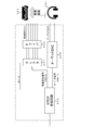
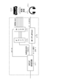
- FIG. 1 shows a configuration example of an AV (Audio / Visual) system 10 as an embodiment.
- the AV system 10 has a television receiver 100 and an audio amplifier 200.
- the television receiver 100 is connected to a television broadcast receiving antenna 121, a BD (Blu-ray Disc) player 122, and the Internet 123.
- the audio amplifier 200 is connected to a 2-channel or multi-channel speaker system 250 and a 1-channel or multi-channel tactile presentation system 260.
- "Blu-ray” is a registered trademark.
- the television receiver 100 and the audio amplifier 200 are connected via an HDMI (High-Definition Multimedia Interface) cable 300.
- HDMI High-Definition Multimedia Interface
- the television receiver 100 is provided with an HDMI terminal 101 to which an HDMI receiving unit (HDMI RX) 102 and a high-speed bus interface 103 constituting a communication unit are connected.
- the audio amplifier 200 is provided with an HDMI terminal 201 in which an HDMI transmission unit (HDMI TX) 202 and a high-speed bus interface 203 constituting a communication unit are connected.
- One end of the HDMI cable 300 is connected to the HDMI terminal 101 of the television receiver 100, and the other end is connected to the HDMI terminal 201 of the audio amplifier 200.
- the television receiver 100 includes an HDMI receiver 102, a high-speed bus interface 103, and an SPDIF (Sony Philips Digital InterFace) transmission circuit 104. Further, the television receiver 100 has a system controller 105, a digital broadcast reception circuit 107, a content reproduction circuit 108, a display unit 109, and an Ethernet interface 110. "Ethernet” and “Ethernet” are registered trademarks. Further, in the illustrated example, each part of the image system is appropriately omitted for simplification of explanation.
- the system controller 105 controls the operation of each part of the television receiver 100.
- the digital broadcast receiving circuit 107 processes the television broadcast signal input from the receiving antenna 121, and processes the video signal related to the broadcast content, the multi-channel audio signal (linear PCM signal), the tactile presentation signal of a predetermined number of channels, and the predetermined number of tactile presentation signals. Outputs metadata that specifies the target tactile presentation position for each of the tactile presentation signals of the number of channels.
- the Ethernet interface 110 communicates with an external server via the Internet 123 to provide a video signal related to net contents, a multi-channel audio signal (linear PCM signal), a tactile presentation signal of a predetermined number of channels, and a tactile presentation of the predetermined number of channels.
- Outputs metadata that specifies the target tactile presentation position for each signal.
- the BD player 122 has a tactile sensation targeted at each of a video signal related to the reproduced content, a multi-channel audio signal (linear PCM signal), a tactile presentation signal of a predetermined number of channels, and a tactile presentation signal of the predetermined number of channels by the reproduction operation.
- Outputs metadata that specifies the presentation position.
- the tactile presentation position (tactile presentation site) targeted by the tactile presentation signal of each channel is limited to, for example, a predefined tactile presentation position range.
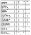
- FIG. 2 shows an example of the tactile presentation position range.
- the full size (32 devices) version, the part 1 size (24 devices) version, the part 2 size (16 devices) version, and the part 3 size (8 devices) version are shown as the tactile presentation position range.
- FIG. 3 schematically shows each tactile presentation position.
- the part 1 size version includes (0) frontal "Head front", (1) head back "Head back", (2) head left “Head left”, (3) head right “Head right”, ( 4) Shoulder left “Shoulder left”, (5) Shoulder right “Shoulder right”, (6) Hand left “Hand left”, (7) Hand right “Hand right”, (8) Wrist left “Wrist left”, ( 9) Wrist right “Wrist right”, (10) Chest upper left “Chest upper-left", (11) Chest upper right “Chest upper-right”, (12) Chest lower left “Chest lower-left", (13) ) Chest lower-right, (14) Belly left “Stomach left”, (15) Belly right “Stomach right”, (16) Back upper left “Back upper-left”, (17) Back upper right “Back upper-right”, (18) lower back left “Back lower-left”, (19) lower back right “Back lower-right”, (20) left knee "Knee left”, (21) right knee "Knee” 24 tactile presentation positions of "right
- the part 2 size version includes (6) left hand “Hand left”, (7) right hand “Hand right”, (8) left wrist “Wrist left”, (9) right wrist “Wrist right”, ( 10) Chest upper-left, (11) Chest upper-right, (12) Chest lower-left, (13) Chest lower-right , (14) Belly left “Stomach left”, (15) Belly right “Stomach right”, (16) Back upper left “Back upper-left”, (17) Back upper right “Back upper-right”, (18) Includes 16 tactile presentation positions: lower back left “Back lower-left”, (19) lower right “Back lower-right”, (22) left foot “Foot left”, (23) right foot “Foot right” Is done.
- the part 3 size version includes (10) upper chest left “Chest upper-left”, (11) upper chest right “Chest upper-right”, (12) lower chest left “Chest lower-left”, (13). ) Chest lower-right, (14) Belly left “Stomach left”, (15) Belly right “Stomach right”, (16) Back upper left “Back upper-left”, (17) Back upper right Includes 8 tactile presentation positions of "Back upper-right”.
- the tactile presentation position targeted by each of the predetermined number of channels of the tactile presentation signal is changed according to the content or dynamically changed in synchronization with the content scene.
- the metadata specifies a target tactile presentation position for each of a predetermined number of tactile presentation signals, but the target tactile presentation position for one channel tactile presentation signal is zero, one, or Multiple tactile presentation positions are possible.
- the content reproduction circuit 108 selectively extracts the video signal, the multi-channel audio signal, the tactile presentation signal of a predetermined number of channels, and the metadata obtained by the digital broadcast reception circuit 107, the Ethernet interface 110, or the BD player 122. Then, the content reproduction circuit 108 sends a video signal to the display unit 109.
- the display unit 109 displays an image based on this video signal.
- the content reproduction circuit 108 sends a multi-channel audio signal and a tactile presentation signal of a predetermined number of channels to the SPDIF transmission circuit 104.
- the SPDIF transmission circuit 104 is a circuit for transmitting an IEC 60958 standard digital audio transmission signal (hereinafter, appropriately referred to as “SPDIF signal”).
- SPDIF signal an IEC 60958 standard digital audio transmission signal
- This SPDIF transmission circuit 104 is a transmission circuit conforming to the IEC60958 standard. The details of the SPDIF signal will be described later.
- the SPDIF transmission circuit 104 simultaneously transmits a multi-channel audio signal and a predetermined number of tactile presentation signals to the audio amplifier 200 with metadata (tactile presentation position information) added.
- a transmission signal for each block consisting of a plurality of frames, here 192 frames, is sequentially transmitted.
- the transmission signal includes a multi-channel audio signal and a predetermined number of tactile presentation signals, and further, the above-mentioned metadata (tactile presentation position information) is added.
- metadata is added using a predetermined bit area of channel status configured for each block.
- the frequency band of the tactile presentation signal is said to be DC-1 kHz.
- a digital audio interface capable of transmitting linear PCM can also transmit a tactile presentation signal.
- expressions such as "push” with a plus, “pull” or “pull” with a minus can be used for the DC region.
- a plurality of frames are composed of repetitions of a multi-channel group consisting of a predetermined number of frames.
- the multi-channel audio signal and the tactile presentation signal of a predetermined number of channels are arranged in a time-division manner for each channel in all or a part of a predetermined number of frames for each multi-channel group.
- the HDMI receiving unit 102 receives video and audio data supplied to the HDMI terminal 101 via the HDMI cable 300 by HDMI-compliant communication.
- the high-speed bus interface 103 is a bidirectional communication path interface configured by using a reserve line and an HPD (Hot Plug Detect) line constituting the HDMI cable 300. The details of the HDMI receiving unit 102 and the high-speed bus interface 103 will be described later.
- the audio amplifier 200 has an HDMI transmission unit 202, a high-speed bus interface 203, and an SPDIF receiving circuit 204. Further, the audio amplifier 200 has a system controller 205, an audio DA converter 206, a selector 207, a driver 208, and an Ethernet interface 210.
- the system controller 205 controls the operation of each part of the audio amplifier 200.
- the HDMI transmission unit 202 transmits video and audio data from the HDMI terminal 201 to the HDMI cable 300 by HDMI-compliant communication.
- the high-speed bus interface 203 is a bidirectional communication path interface configured by using a reserve line and an HPD (Hot Plug Detect) line constituting the HDMI cable 300. The details of the HDMI transmission unit 202 and the high-speed bus interface 203 will be described later.
- the SPDIF receiving circuit 204 receives a transmission signal as an SDPIF signal (IEC 60958 standard digital audio signal), and acquires a multi-channel audio signal included in the transmission signal, a tactile presentation signal of a predetermined number of channels, and metadata.
- SDPIF signal ISO 60958 standard digital audio signal
- the audio DA converter 206 DA-converts the multi-channel audio signal extracted by the SPDIF receiving circuit 204 for each channel, amplifies it, and sends it to the speaker system 250 having a speaker corresponding to each channel. As a result, the speaker system 250 performs audio reproduction using the multi-channel audio signal.
- the selector 207 presents the tactile presentation signals of a predetermined number of channels extracted by the SPDIF receiving circuit 204 based on the metadata extracted by the SPDIF receiving circuit 204, respectively, at the target tactile presentation position. It is distributed and output as a signal.
- the driver 208 DA-converts and amplifies the tactile presentation signals of a predetermined number of channels distributed by the selector 207, and sends them to the tactile presentation system 260 having a tactile presentation device at each tactile presentation position.
- the tactile presentation reproduction at each target tactile presentation position is performed by the tactile presentation signals of a predetermined number of channels.
- the tactile presentation signal of a predetermined number of channels is sent at the same time as the multi-channel audio signal, this tactile presentation reproduction is correctly synchronized with the audio reproduction, and the television receiver It is also synchronized with the video display on the display unit 109 of 100.
- the multi-channel audio signal will be described as a 2-channel stereo audio signal
- the tactile presentation signal of a predetermined number of channels will be described as a 4-channel tactile presentation signal.
- the present technology is not limited to this.
- FIG. 4 shows a configuration example of the parts of the SPDIF receiving circuit 204, the audio DA converter 206, the selector 207, and the driver 208 in the audio amplifier 200.
- the 2-channel stereo audio signal (signal of channels 0 and 1) taken out by the SPDIF receiving circuit 204 is supplied to the audio DA converter 206.
- the two-channel stereo audio signal (left audio signal, right audio signal) is DA-converted and amplified, and supplied to the headphone 251 as the speaker system 250.
- the headphones 251 perform audio reproduction using the 2-channel stereo audio signal.
- the metadata of the four-channel tactile presentation signal (signals of channels 2 to 5) extracted by the SPDIF receiving circuit 204 and the tactile presentation position to be targeted by each of the four-channel tactile presentation signals are It is supplied to the selector 207.
- the tactile presentation signals of the four channels are distributed and output as the tactile presentation signals of the tactile presentation positions (included in the six tactile presentation positions) of each target based on the metadata.
- the four-channel tactile presentation signals distributed by the selector 207 are DA-converted and amplified by the driver 208, and then correspond to the tactile presentation best 261 having the tactile presentation device and the tactile presentation sofa 262 as the tactile presentation system 260. It is supplied to the tactile presentation device. As a result, vibration reproduction is performed at each target tactile presentation position by the tactile presentation signals of the four channels.
- the "circle” indicates the tactile presentation position (arrangement position of the tactile presentation device), and there are a total of 6 tactile presentation positions.
- the six tactile presentation positions are sofa left, sofa right, chest left, chest right, belly left, and belly right.
- FIG. 5 shows a tactile vibration signal distribution function included in the selector 207.
- the selector 207 is configured to be able to output a tactile presentation signal of a certain channel (channel x) as a tactile presentation signal at a predetermined tactile presentation position based on metadata.
- the selector 207 is configured to be able to output tactile presentation signals of a plurality of channels as tactile presentation signals at a certain tactile presentation position based on metadata.
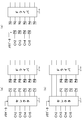
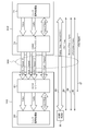
- FIG. 6 shows a configuration example of the selector 207.
- the selector 207 has four input systems In1 to In4 for inputting four channels of tactile presentation signals as input terminals. Further, the selector 207 has six output systems Out1 to Out6. Then, each output system has an input unit that selectively inputs zero, one, or a plurality of four-channel tactile presentation signals input to the four-input systems In1 to In4 based on the metadata. It is equipped with a totaling unit that totals and outputs each input tactile presentation signal. With this configuration, the selector 207 functions as the sorting function shown in FIGS. 5A and 5B described above.
- FIG. 7 shows a configuration example in which a part of the path of the SPDIF receiving circuit 204, the selector 207, and the driver 208 is made wireless.
- Tx indicates a wireless transmitter
- Rx indicates a wireless receiver.
- FIG. 7A all six paths between the six outputs of the selector 207 and the six inputs of the driver 208 are wireless.
- FIG. 7B only a part of the paths between the 6 outputs of the selector 207 and the 6 inputs of the driver 208, or 4 paths in the illustrated example, are wireless.
- the four outputs of the SPDIF receiving circuit 204 and the six inputs of the driver 208 are wireless.
- the transmitters related to the four outputs of the SPDIF receiving circuit 204 have the function of the selector 207, and based on the metadata, selectively transmit the tactile presentation signals to the receivers related to the six inputs of the driver 208. To do.
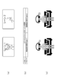
- FIG. 8 shows an example of audiovisual content reproduction.
- FIG. 8A schematically shows scenes 1 (scenes that are hitting each other) and scenes 2 (scenes that are down) that are continuous in chronological order.
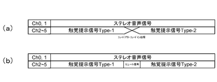
- FIG. 8B shows a continuous 2-channel stereo audio signal and a 4-channel tactile presentation signal that dynamically changes in synchronization with the scene.
- the 4-channel tactile presentation signal corresponding to scene 1 is indicated by type 1.
- the tactile presentation signals of the four channels of the 0th channel, the 1st channel, the 2nd channel, and the 3rd channel are the vibration positions of the chest left, chest right, belly left, and belly right as shown in FIG. Is targeted.
- circled numbers 0, 1, 2, and 3 indicate the 0th channel, the 1st channel, the 2nd channel, and the 3rd channel, respectively.
- the tactile presentation signals of the four channels of the 0th channel, the 1st channel, the 2nd channel, and the 3rd channel are the chest left, chest right, and abdominal left, respectively. It is output as a tactile presentation signal of the vibration position on the right side of the abdomen.
- the sensation of being beaten is produced at the tactile presentation positions of the chest left, chest right, belly left, and belly right (see the white “circle”). Tactile presentation reproduction is performed.
- the 4-channel tactile presentation signal corresponding to scene 2 is indicated by type 2.
- the tactile presentation signals of the four channels of the 0th channel, the 1st channel, the 2nd channel, and the 3rd channel are the tactile presentations of the chest left, chest right, sofa left, and sofa right as shown in FIG. Target the position.
- the selector 207 outputs the four-channel tactile presentation signals as tactile presentation signals at the tactile presentation positions of the chest left, chest right, sofa left, and sofa right, respectively.
- the tactile sensation is moved from the front to the back at the tactile presentation positions of the chest left, chest right, sofa left, and sofa right (see the white “circle”).
- tactile presentation reproduction is performed to produce a down tactile sensation that falls backward after an impact.
- the 2-channel stereo audio signal is continuously reproduced without a break, and only the tactile presentation signal is switched discontinuously. Since the tactile presentation signal is discontinuous between the scene 1 and the scene 2, as shown in FIG. 10A, when switching between the tactile presentation signals, the tactile presentation signal is faded out or faded in, or the tactile presentation signal is faded out or faded in. As shown in FIG. 10B, it is desirable to perform a mute signal insertion process on the tactile presentation signal at the time of switching. This makes it possible to alleviate the discomfort of the user due to the discontinuous change of the tactile presentation signal.
- the fade-out / fade-in process and the mute signal insertion process may be performed in advance on the television receiver 100 side, may be performed by the selector 207 or the driver 208 of the audio amplifier 200, or the tactile presentation best 261 or the tactile sensation. It may be done on the presentation sofa 262.
- FIG. 11 shows another configuration example of the parts of the SPDIF receiving circuit 204, the audio DA converter 206, the selector 207, and the driver 208 in the audio amplifier 200.
- the parts corresponding to those in FIG. 4 are designated by the same reference numerals.
- the other configuration examples differ from the configuration example of FIG. 4 in that the connection order of the selector 207 and the driver 208 is reversed, and the other configurations are the same.
- FIG. 12 shows a configuration example of the HDMI receiving unit 102 of the television receiver 100 and the HDMI transmitting unit 202 of the audio amplifier 200 in the AV system 10 of FIG.
- the HDMI transmission unit 202 is a valid image section which is a section from a certain vertical synchronization signal to the next vertical synchronization signal (hereinafter, appropriately referred to as “video field”) excluding the horizontal blanking period and the vertical blanking period.
- video field the next vertical synchronization signal
- active video section the differential signal of the image data for one screen of the base band (uncompressed) is transmitted to the HDMI receiving unit 102 in one direction by a plurality of channels.
- the HDMI transmission unit 202 transmits a plurality of differential signals corresponding to voice data and control packets (Control Packet) accompanying the image data, other auxiliary data, and the like during the horizontal blanking period and the vertical blanking period.
- the channel transmits data to the HDMI receiving unit 102 in one direction.
- the HDMI transmission unit 202 has a source signal processing unit 71 and an HDMI transmitter 72.
- Baseband uncompressed image (Video) and audio (Audio) data are supplied to the source signal processing unit 71.
- the source signal processing unit 71 performs necessary processing on the supplied image and audio data, and supplies the HDMI transmitter 72. Further, the source signal processing unit 71 exchanges control information, status information (Control / Status), and the like with the HDMI transmitter 72, if necessary.
- the HDMI transmitter 72 converts the image data supplied from the source signal processing unit 71 into corresponding differential signals, and connects the HDMI cable 300 with three TMDS channels # 0, # 1, and # 2, which are a plurality of channels. It transmits in one direction to the HDMI receiving unit 102 connected via the device.
- auxiliary data associated with uncompressed image data supplied from the HDMI transmitter 72 and the source signal processing unit 71, a vertical synchronization signal (VSYNC), and a horizontal synchronization signal (VSYNC).
- VSYNC vertical synchronization signal
- VSYNC horizontal synchronization signal
- HSYNC auxiliary data and other control data are converted into corresponding differential signals, and the HDMI receiver 102 connected via the HDMI cable 300 on the three TMDS channels # 0, # 1, and # 2. To send in one direction.
- the HDMI transmitter 72 connects the pixel clock synchronized with the image data transmitted through the three TMDS channels # 0, # 1 and # 2 to the HDMI receiver 102 via the HDMI cable 300 on the TMDS clock channel. Send to.
- the HDMI receiving unit 102 receives the differential signal corresponding to the image data transmitted in one direction from the HDMI transmitting unit 202 on a plurality of channels in the active video section, and also has a horizontal blanking period and a vertical blanking period. In the plurality of channels, the differential signals corresponding to the auxiliary data and the control data transmitted from the HDMI transmission unit 202 are received.
- the HDMI receiving unit 102 includes an HDMI receiver 81 and a sink signal processing unit 82.
- the HDMI receiver 81 is a differential signal corresponding to image data transmitted in one direction from the HDMI transmission unit 202 connected via the HDMI cable 300 on TMDS channels # 0, # 1, and # 2.
- the differential signal corresponding to the auxiliary data and the control data is received in synchronization with the pixel clock transmitted from the HDMI transmission unit 202 on the TMDS clock channel. Further, the HDMI receiver 81 converts the differential signal into corresponding image data, auxiliary data, and control data, and supplies the differential signal to the sync signal processing unit 82 as needed.
- the sink signal processing unit 82 performs necessary processing on the data supplied from the HDMI receiver 81 and outputs the data. In addition, the sync signal processing unit 82 exchanges control information, status information (Control / Status), and the like with the HDMI receiver 81, if necessary.
- the HDMI transmission channels include three TMDS channels for serially transmitting image data, auxiliary data, and control data from the HDMI transmission unit 202 to the HDMI reception unit 102 in one direction in synchronization with the pixel clock.
- TMDS Serial Data Channel
- a TMDS clock channel as a transmission channel for transmitting a pixel clock, there are a DDC (Display Data Channel) 83 and a transmission channel called a CEC line 84.
- the DDC 83 is composed of two lines (signal lines) (not shown) included in the HDMI cable 300, and the source device performs E-EDID (Enhanced-Extended Display Identification) from the sink device connected via the HDMI cable 300. Used to read. That is, the sink device has an EDID ROM 85. The source device reads the E-EDID stored in the EDID ROM 85 from the sink device connected via the HDMI cable 300 via the DDC 83, and recognizes the setting and performance of the sink device based on the E-EDID. To do.
- E-EDID Enhanced-Extended Display Identification
- the CEC line 84 consists of one line (not shown) included in the HDMI cable 300, and is used for bidirectional communication of control data between the source device and the sink device.
- the HDMI cable 300 includes a line 86 connected to a pin called HPD (Hot Plug Detect).
- HPD Hot Plug Detect
- the source device can detect the connection of the sink device by using the line 86.
- the HDMI cable 300 also includes a line 87 used to supply power from the source device to the sink device.
- the HDMI cable 300 includes a reserve line 88.
- FIG. 13 shows a configuration example of the high-speed bus interface 103 of the television receiver 100 in the AV system 10 of FIG.
- the Ethernet interface 110 performs LAN (Local Area Network) communication, that is, transmission / reception of Ethernet signals, using a transmission line composed of a pair of reserve lines and HPD lines among a plurality of lines constituting the HDMI cable 300.
- the SPDIF transmission circuit 104 transmits an SPDIF signal using a transmission line composed of the pair of lines described above.
- the television receiver 100 has a LAN signal transmission circuit 441, a terminating resistor 442, an AC coupling capacitance 443, 444, a LAN signal reception circuit 445, a subtraction circuit 446, an addition circuit 449, 450, and an amplifier 451. These constitute the high-speed bus interface 103. Further, the television receiver 100 has a choke coil 461, a resistor 462, and a resistor 463 that form a plug connection transmission circuit 128.
- a series circuit of AC coupling capacitance 443, terminating resistor 442 and AC coupling capacitance 444 is connected between the 14-pin terminal 521 and the 19-pin terminal 522 of the HDMI terminal 101. Further, a series circuit of the resistor 462 and the resistor 463 is connected between the power supply line (+ 5.0V) and the ground line. Then, the connection points of the resistors 462 and 463 are connected to the connection point Q4 between the 19-pin terminal 522 and the AC coupling capacitance 444 via the choke coil 461.
- connection points P3 of the AC coupling capacitance 443 and the terminating resistor 442 are connected to the output side of the adder circuit 449 and to the positive input side of the LAN signal reception circuit 445. Further, the connection points P4 of the AC coupling capacitance 444 and the terminating resistor 442 are connected to the output side of the adder circuit 450 and to the negative input side of the LAN signal reception circuit 445.
- One input side of the adder circuit 449 is connected to the positive output side of the LAN signal transmission circuit 441, and the SPDIF signal output from the SPDIF transmission circuit 104 is supplied to the other input side of the adder circuit 449 via the amplifier 451. Will be done. Further, one input side of the adder circuit 450 is connected to the negative output side of the LAN signal transmission circuit 441, and the SPDIF signal output from the SPDIF transmission circuit 104 is transmitted to the other input side of the adder circuit 450 via the amplifier 451. Is supplied.
- a transmission signal (transmission data) SG417 is supplied from the Ethernet interface 110 to the input side of the LAN signal transmission circuit 441. Further, the output signal SG418 of the LAN signal receiving circuit 445 is supplied to the positive terminal of the subtraction circuit 446, and the transmission signal SG417 is supplied to the negative terminal of the subtraction circuit 446. In this subtraction circuit 446, the transmission signal SG417 is subtracted from the output signal SG418 of the LAN signal reception circuit 445, and the reception signal (reception data) SG419 is obtained. The received signal SG419 becomes the LAN signal when the LAN signal (Ethernet signal) is transmitted as a differential signal via the reserve line and the HPD line. The received signal SG419 is supplied to the Ethernet interface 110.
- FIG. 14 shows a configuration example of the high-speed bus interface 203 of the audio amplifier 200 in the AV system 10 of FIG.
- the Ethernet interface 210 performs LAN (Local Area Network) communication, that is, transmission / reception of Ethernet signals, using a transmission line composed of a pair of reserve lines and HPD lines among a plurality of lines constituting the HDMI cable 300. ..
- the SPDIF receiving circuit 204 receives the SPDIF signal using the transmission line composed of the pair of lines described above.
- the audio amplifier 200 includes a LAN signal transmission circuit 411, a terminating resistor 412, an AC coupling capacitance 413, 414, a LAN signal reception circuit 415, a subtraction circuit 416, an adder circuit 419, and an amplifier 420. These constitute the high-speed bus interface 203. Further, the audio amplifier 200 has a pull-down resistor 431, a resistor 432, a capacitance 433, and a comparator 434 that constitute the plug connection detection circuit 221. Here, the resistor 432 and the capacitance 433 form a low-pass filter.
- a series circuit of AC coupling capacitance 413, terminating resistor 412 and AC coupling capacitance 414 is connected between the 14-pin terminal 511 and the 19-pin terminal 512 of the HDMI terminal 201.
- the connection points P1 of the AC coupling capacitance 413 and the terminating resistor 412 are connected to the positive output side of the LAN signal transmission circuit 411 and to the positive input side of the LAN signal reception circuit 415.
- connection points P2 of the AC coupling capacitance 414 and the terminating resistor 412 are connected to the negative output side of the LAN signal transmission circuit 411 and to the negative input side of the LAN signal reception circuit 415.
- a transmission signal (transmission data) SG411 is supplied from the Ethernet interface 210 to the input side of the LAN signal transmission circuit 411.
- the output signal SG412 of the LAN signal receiving circuit 415 is supplied to the positive terminal of the subtraction circuit 416, and the transmission signal (transmission data) SG411 is supplied to the negative terminal of the subtraction circuit 416.
- the transmission signal SG411 is subtracted from the output signal SG412 of the LAN signal reception circuit 415, and the reception signal SG413 is obtained.
- the received signal SG413 becomes the LAN signal when the LAN signal (Ethernet signal) is transmitted as a differential signal via the reserve line and the HPD line.
- the received signal SG413 is supplied to the Ethernet interface 210.
- connection point Q2 between the AC coupling capacitance 414 and the 19-pin terminal 512 is connected to the ground wire via the pull-down resistor 431 and is also connected to the ground wire via the series circuit of the resistor 432 and the capacitance 433. Then, the output signal of the low-pass filter obtained at the connection point between the resistor 432 and the capacitance 433 is supplied to one input terminal of the comparator 434.
- the output signal of the low-pass filter is compared with the reference voltage Vref2 (+ 1.4V) supplied to the other input terminal.
- the output signal SG415 of the comparator 434 is supplied to a control unit (CPU) (not shown) of the audio amplifier 200.
- connection point P1 of the AC coupling capacitance 413 and the terminating resistor 412 is connected to one input terminal of the adder circuit 419. Further, the connection points P2 of the AC coupling capacitance 414 and the terminating resistor 412 are connected to the other input terminal of the adder circuit 419.
- the output signal of the adder circuit 419 is supplied to the SPDIF receiving circuit 204 via the amplifier 420.
- the output signal of the addition circuit 419 becomes the SPDIF signal when the SPDIF signal is transmitted as an in-phase signal via the reserve line and the HPD line.
- FIG. 15 shows the frame configuration in the IEC 60958 standard.
- Each frame consists of two subframes.
- the first subframe contains the left channel signal and the second subframe contains the right channel signal.
- a preamble is provided at the beginning of the subframe as described later, and "M” is given as a preamble to the left channel signal and “W” is given as a preamble to the right channel signal. However, every 192 frames, "B” indicating the start of the block is added to the first preamble. That is, one block is composed of 192 frames.
- a block is a unit that constitutes a channel status described later.
- FIG. 16 shows the subframe configuration in the IEC60958 standard.
- the subframe is composed of a total of 32 time slots from the 0th to the 31st.
- the 0th to 3rd time slots indicate a preamble (Sync preamble).
- This preamble indicates either "M", "W” or "B” in order to distinguish the left and right channels and to indicate the start position of the block as described above.
- the 4th to 27th time slots are the main data fields, and when the 24-bit code range is adopted, the whole represents audio data.
- the 8th to 27th time slots represent audio data (Audio sample word).
- the 4th to 7th time slots can be used as additional information (Auxiliary sample bits). The illustrated example shows the latter case.
- the 28th time slot is a valid flag (Validity flag) of the main data field.
- the 29th time slot represents one bit of user data (User data).
- a series of user data can be constructed by accumulating the 29th time slot over each frame.
- This user data message is configured in units of 8-bit information units (IU: Information Units), and one message includes 3 to 129 information units.
- the head of the information unit is identified by the start bit "1".
- the first seven information units in the message are reserved, and the user can set arbitrary information in the eighth and subsequent information units.
- the messages are divided by "0" of 8 bits or more.
- the 30th time slot represents one bit of channel status.
- a series of channel statuses can be configured by accumulating the 30th time slot for each block across each frame.
- the start position of the block is indicated by the preamble (0th to 3rd time slots) of "B" as described above.
- the 31st time slot is a parity bit. This parity bit is assigned so that the number of "0" and "1" contained in the fourth to 31st time slots is an even number.
- a multi-channel transmission format based on the IEC60958 standard is used to target the above-mentioned 2-channel stereo audio signal and 4-channel tactile presentation signal, respectively of the 4-channel tactile presentation signal. It is transmitted at the same time with the metadata that specifies the tactile presentation position to be added.
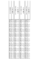
- FIG. 17 shows an example of a frame configuration of a multi-channel transmission format when a 2-channel stereo audio signal and a 4-channel tactile presentation signal are simultaneously transmitted.
- one block is composed of 192 frames, and this 192 frames consists of repeating a multichannel group consisting of a predetermined number of subframes. Each subframe part constitutes a multichannel order. The number of subframes to be included in the multi-channel group can be indicated by using a predetermined bit area of the channel status configured for each block.
- Multi-channel subgroups consist of one or more multi-channel orders.
- the signals of each channel of the multi-channel audio signal are sequentially arranged in each multi-channel order constituting this multi-channel subgroup.
- What kind of multi-channel subgroup is formed in the multi-channel group can be indicated by using a predetermined bit area of the channel status configured for each block, and by using a predetermined number of frames of user data bits. Can also be shown.
- one multi-channel group is composed of 6 subframes, that is, multi-channel orders 1 to 6. Further, one multi-channel subgroup of the multi-channel subgroup 1 is formed in the multi-channel group. Then, in this example, the two-channel stereo audio signal and the four-channel tactile presentation signal are simultaneously transmitted by the one multi-channel subgroup.
- the front left (FL) audio signal, the front right (FR) audio signal, the 0th channel (Haptic_0) tactile presentation signal, and the 1st channel (Haptic_1) are in the multi-channel orders 1 to 6 constituting the multi-channel subgroup 1.
- Tactile presentation signal, the second channel (Haptic_2) tactile presentation signal, and the third channel (Haptic_3) tactile presentation signal are arranged in this order.
- the metadata that specifies the target tactile presentation position for each of the four channels of tactile presentation signals is added, for example, using a predetermined bit area of the channel status configured for each block.
- a method of adding metadata using a predetermined bit area of the channel status for example, the following first to third methods can be considered.
- the first method is a method of designating the target tactile presentation position for each of the four channels of the tactile presentation signal by the mapping type.
- FIG. 18 schematically shows the format of the channel status in the IEC60958 standard.
- the channel status is the cumulative 30th time slot in the subframe for each block (see FIG. 16).
- the contents of the channel status are arranged one byte at a time in the vertical direction, and the bit configuration in each byte is shown in the horizontal direction.
- the format for consumer use will be assumed.
- the 0th bit (bit 0) a is set to “0", indicating that this channel status is for consumer use. Further, b of the first bit (bit 1) is set to "0", indicating that the sample is a linear PCM sample.
- the 6th and 7th bits (bits 6-7) indicate the mode of the channel status.
- the 44th to 47th bits constitute a 4-bit field of "Multichannel Count", and the number of subframes to be included in the multichannel group is shown. Here, it is shown that the number of subframes included in the multi-channel group is "6".
- the 53rd to 60th bits constitute an 8-bit field of "Multichannel configuration value", and the configuration of the multichannel subgroup is shown.
- the signal configuration is 6 channels including a 2-channel stereo audio signal and a 4-channel tactile presentation signal.
- the xxth bit to the xx + 7th bit of the xth byte constitute an 8-bit field of "Haptic channel mapping type", and each of the four channel tactile presentation signals is a mapping that specifies a target tactile presentation position.
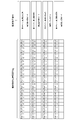
- the type is shown. For example, as shown in FIG. 19, “00000001” indicates type 1 (Type-1), “00000010” indicates type 2 (Type-2), and “00000011” indicates type 3 (Type-3). , "00000100” indicates Type 4 (Type-4).
- the tactile presentation position targeted by each of the four channels of tactile presentation signals is defined in advance for each type.
- the tactile presentation signals of the 0th, 1st, 2nd, and 3rd channels are chest left and chest right, respectively.
- Stomach left, Stomach right, and in the case of type 2 (Type-2) the tactile presentation signals of channels 0, 1, 2, and 3 are chest left and chest, respectively.
- Right, sofa left (Sofa left), sofa right (Sofa right) are targeted, and in the case of type 3 (Type-3), the tactile presentation signals of the 0th, 1st, 2nd, and 3rd channels are the belly left and the belly left, respectively.
- the tactile presentation signals of channels 0, 1, 2, and 3 are for chest left, belly left, and sofa left, respectively.
- the third channel is N.I. A. Indicates that (not available).
- the second method is a method of designating the tactile presentation position targeted by each of the tactile presentation signals of the four channels by setting a flag in the corresponding bit of the channel allocation.
- FIG. 21 schematically shows the format of the channel status in the IEC60958 standard.
- the description of the portion corresponding to FIG. 18 will be omitted as appropriate.
- the 44th to 47th bits constitute a 4-bit field of "Multichannel Count", and the number of subframes to be included in the multichannel group is shown. Here, it is shown that the number of subframes included in the multi-channel group is "6".
- the 53rd to 60th bits constitute an 8-bit field of "Multichannel configuration value", and the configuration of the multichannel subgroup is shown.
- the signal configuration is 6 channels including a 2-channel stereo audio signal and a 4-channel tactile presentation signal.
- the xxth bit to the xx + 7th bit of the xth byte constitute an 8-bit field of "Haptic channel 0 allocation", and the channel allocation of the tactile presentation signal of the 0th channel is shown.
- the xxth bit, the xx + 1 bit, the xx + 2 bit, the xx + 3 bit, the xx + 4 bit, and the xx + 5 bit are the chest left and the chest right, respectively.
- the tactile presentation position targeted by the tactile presentation signal of the 0th channel is specified.
- the xx + 8th bit to the xx + 15th bit of the x + 1 byte constitute an 8-bit field of "Haptic channel 1 allocation", and the channel allocation of the tactile presentation signal of the first channel is shown.
- the xx + 8 bits, the xx + 9 bits, the xx + 10 bits, the xx + 11 bits, the xx + 12 bits, and the xx + 13 bits are the chest left and the chest right, respectively.
- the tactile presentation position targeted by the tactile presentation signal of the first channel is specified.
- the xx + 16 bits to the xx + 23 bits of the xx + 2 bytes constitute an 8-bit field of "Haptic channel 2 allocation", and the channel allocation of the tactile presentation signal of the second channel is shown.
- the xx + 16 bits, the xx + 17 bits, the xx + 18 bits, the xx + 19 bits, the xx + 20 bits, and the xx + 21 bits are the chest left and the chest right, respectively.
- the tactile presentation position targeted by the tactile presentation signal of the second channel is specified.
- the xx + 24 bits to the xx + 31 bits of the xx + 3 bytes constitute an 8-bit field of "Haptic channel 3 allocation", and the channel allocation of the tactile presentation signal of the third channel is shown.
- the xx + 24 bits, the xx + 25 bits, the xx + 26 bits, the xx + 27 bits, the xx + 28 bits, and the xx + 29 bits are the chest left and the chest right, respectively.
- the tactile presentation position targeted by the tactile presentation signal of the third channel is specified.
- the third method is a method of designating the tactile presentation position targeted by each of the four channels of the tactile presentation signal by a number defined in advance for the tactile presentation position.
- FIG. 24 schematically shows the format of the channel status in the IEC60958 standard.
- the description of the portion corresponding to FIG. 18 will be omitted as appropriate.
- the 44th to 47th bits constitute a 4-bit field of "Multichannel Count", and the number of subframes to be included in the multichannel group is shown. Here, it is shown that the number of subframes included in the multi-channel group is "6".
- the 53rd to 60th bits constitute an 8-bit field of "Multichannel configuration value", and the configuration of the multichannel subgroup is shown.
- the signal configuration is 6 channels including a 2-channel stereo audio signal and a 4-channel tactile presentation signal.
- the xx bits to xx + 3 bits of the xth byte constitute a 4-bit field of "Haptic channel 0 position number_1", and the tactile presentation signal of the 0th channel is the target of the first tactile presentation position.
- the position number is shown, and the x + 4th to xx + 7 bits of the xth byte constitute a 4-bit field of "Haptic channel 0 position number_2", and the second tactile presentation signal of the 0th channel is targeted.
- the position number of the tactile presentation position is shown.
- FIG. 25 shows an example of the correspondence between the position number and the tactile presentation position.
- the position number "0000” indicates the chest left (Chest left)
- the position number "0001” indicates the chest right (Chest right)
- the position number "0010” indicates the belly left (Stomach left)
- the position number "0011” indicates the belly right (Stomach right)
- the position number "0100” indicates the sofa left (Sofa left)
- the position number "0101” indicates the sofa right (Sofa right).
- If there is no target tactile presentation position it is set to, for example, "1111".
- the xx + 8 bits to the xx + 11 bits of the x + 1 bytes constitute a 4-bit field of "Haptic channel 1 position number_1", and the tactile presentation signal of the first channel is the target of the first tactile presentation position.
- the position number is shown, and the xx + 12 bits to xx + 15 bits of the x + 1 byte constitute a 4-bit field of "Haptic channel 1 position number_2", and the second tactile presentation signal of the first channel is targeted.
- the position number of the tactile presentation position is shown.
- the xx + 16 bits to the xx + 19 bits of the x + 2 bytes constitute a 4-bit field of "Haptic channel 2 position number_1", and the tactile presentation signal of the second channel is the target of the first tactile presentation position.
- the position number is shown, and the xx + 20 bits to xx + 23 bits of the x + 2 bytes constitute a 4-bit field of "Haptic channel 2 position number_2", and the second tactile presentation signal of the second channel is targeted.
- the position number of the tactile presentation position is shown.
- the xx + 24 bits to the xx + 27 bits of the x + 3 bytes constitute a 4-bit field of "Haptic channel 3 position number_1", and the tactile presentation signal of the third channel is the target of the first tactile presentation position.
- the position number is shown, and the xx + 28 bits to xx + 31 bits of the xx + 3 bytes constitute a 4-bit field of "Haptic channel 3 position number_2", and the second tactile presentation signal of the third channel is targeted.
- the position number of the tactile presentation position is shown.
- each of the tactile presentation positions of a predetermined number of channels is targeted by the transmission signal including the audio signal of a predetermined number of channels and the tactile presentation signal of a predetermined number of channels. Is added and transmitted from the television receiver 100 to the audio amplifier 200. Therefore, on the receiving side, the tactile presentation signal of a predetermined number of channels can be output as the tactile presentation signal of the target tactile presentation position based on the metadata, and the position is larger than the number of channels of the tactile presentation signal that can be transmitted. Tactile presentation is possible.
- the metadata added to the transmission signal is dynamically changed in synchronization with, for example, the scene in the content, and each of the tactile presentation signals of a predetermined number of channels is targeted.
- the tactile presentation position can be dynamically changed.
- the tactile presentation position targeted by the tactile presentation signals of a predetermined number of channels can be dynamically changed based on the metadata, and effective tactile presentation can be performed.
- FIG. 26 shows another example of audiovisual content reproduction.
- the tactile presentation position (tactile presentation device) is head front "Head front”, head back “Head back”, head left “Head left”, head right “Head right”, shoulder left “Shoulder left”, shoulder.
- the tactile presentation signals of the 4 channels of the 0th channel, the 1st channel, the 2nd channel, and the 3rd channel are the tactile presentation positions of the left knee, the right knee, the left foot, and the right foot, respectively. Is targeted.
- the tactile presentation signals of the 4 channels of the 0th channel, the 1st channel, the 2nd channel, and the 3rd channel are the tactile senses of the left knee, the right knee, the left abdomen, and the right abdomen, respectively. Target the presentation position.
- the tactile presentation signals of the 4 channels of the 0th channel, the 1st channel, the 2nd channel, and the 3rd channel are the lower chest left, the lower chest right, the belly left, and the belly right, respectively.
- the tactile presentation position of is targeted.
- the tactile presentation signals of the 4 channels of the 0th channel, the 1st channel, the 2nd channel, and the 3rd channel are the lower chest left, the lower chest right, the upper chest left, and the chest, respectively.
- the target is the tactile presentation position on the upper right.
- the tactile presentation signals of the 4 channels of the 0th channel, the 1st channel, the 2nd channel, and the 3rd channel are shoulder left, shoulder right, chest left, and chest right, respectively.
- the tactile presentation position of is targeted.
- the tactile presentation signals of the four channels of the 0th channel, the 1st channel, the 2nd channel, and the 3rd channel are the tactile sensations of the shoulder left, the shoulder right, the head left, and the head right, respectively.
- the tactile presentation signals of the four channels of the 0th channel, the 1st channel, the 2nd channel, and the 3rd channel are the tactile sensations of the frontal, posterior, head left, and head right, respectively.
- the tactile presentation position targeted by the tactile presentation signal of 4 channels moves from the foot to the head for each scene, and the tactile presentation is performed by the foot. You can express in detail the feeling of rising from the head to the head.
- FIG. 27 shows yet another example of audiovisual content reproduction.
- This example is an example in which there are 24 tactile presentation positions (tactile presentation devices) as in the example of FIG. 26.
- the circled numbers 0, 1, 2, and 3 indicate the 0th channel, the 1st channel, the 2nd channel, and the 3rd channel, respectively.
- the tactile presentation signal of the 0th channel targets the tactile presentation positions of the front, back, left, and right of the head, and the tactile presentation signal of the 1st channel is the shoulder left, shoulder right, and so on.
- the tactile presentation positions of the left hand, right hand, left wrist, and right wrist are targeted, and the tactile presentation signals of the second channel are chest left, chest right, chest left, chest right, belly left, belly right, and back.
- the tactile presentation positions of upper left, upper back right, lower back left and lower back right are targeted, and the tactile presentation signals of the third channel target the tactile presentation positions of knee left, knee right, foot left and foot right.
- all the tactile presentation positions are targeted by any of the tactile presentation signals from the 0th channel to the 3rd channel, and for example, the tactile presentation that gives an impact to the whole body can be performed.
- the tactile presentation signal of the 0th channel targets the tactile presentation positions of the left above the chest and the right above the chest, and the tactile presentation signal of the 1st channel is the left below the chest and the right below the chest.
- the tactile presentation position is targeted
- the tactile presentation signal of the second channel is targeted at the tactile presentation position of the abdominal left and the ventral right
- the tactile presentation signal of the third channel is targeted at the tactile presentation position of the left knee and the right knee.
- the tactile presentation signals of channel 0 are head left, shoulder left, hand left, wrist left, chest left, chest bottom left, abdominal left, back top left, back bottom left,
- the tactile presentation positions of the left knee and left foot are targeted, and the tactile presentation signals of the first channel are head right, shoulder right, hand right, wrist right, chest right, chest lower right, abdominal right, back upper right, lower back.
- the tactile presentation positions on the right, right knee, and right foot are targeted.
- the tactile presentation signal of the 0th channel targets the tactile presentation positions of the upper chest left, the upper chest right, the lower chest left, the lower chest right, the abdominal left and the abdominal right, and the first The tactile presentation signal of the channel targets the tactile presentation positions of the left and right chest, the tactile presentation signal of the second channel targets the tactile presentation position of the left knee and the right knee, and the tactile presentation signal of the third channel The tactile presentation positions on the left and right feet are targeted.
- the tactile presentation signal of the 0th channel are the targets of the tactile presentation signal of the 0th channel and the tactile presentation signal of the 1st channel, a complicated impact is given to the upper body, and another impact is given to the knee and the foot. Tactile presentation can be made to give.
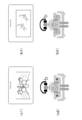
- FIG. 28 shows yet another example of audiovisual content reproduction.
- the tactile presentation position (tactile presentation device) is head front "Head front”, head back “Head back”, head left “Head left”, head right “Head right”, shoulder left “Shoulder left”, shoulder.
- the tactile presentation signal of the 0th channel targets the tactile presentation position of the floor front left and the floor front right, and the tactile presentation signal of the 1st channel is the floor back left and the floor back.
- the tactile presentation position of the right channel is targeted
- the tactile presentation signal of the second channel is targeted at the tactile presentation position of the left foot and the right foot
- the tactile presentation signal of the third channel is the sofa seat front left and the sofa seat front.
- the tactile presentation positions on the right, sofa seat back left, and sofa seat back right are targeted. In this case, for example, it is possible to present the tactile sensation of the earth's sound with an emphasis on the feet and the bottom.
- the tactile presentation signal of the 0th channel targets the tactile presentation position on the left side of the controller
- the tactile presentation signal of the 1st channel targets the tactile presentation position on the right side of the controller
- the second channel targets the tactile presentation positions of the upper chest left, the lower chest left, and the abdominal left
- the tactile presentation signal of the second channel targets the tactile presentation positions of the upper chest right, the lower chest right, and the abdominal right.
- tactile presentation corresponding to an action scene in which an item is held can be performed.
- the tactile presentation signal of the 0th channel targets the tactile presentation positions of the table left and the table far left
- the tactile presentation signal of the first channel is the tactile presentation of the table right and the table far right
- the tactile presentation signal of the second channel targets the tactile presentation position on the left side of the sofa backrest
- the tactile presentation signal of the third channel targets the tactile presentation position on the right side of the sofa backrest.
- a horror effect can be produced by placing a hand on the table.
- the tactile presentation signal of the 0th channel targets the tactile presentation position on the left of the sofa backrest and the left of the sofa seat back, and the tactile presentation signal of the 1st channel is the sofa back.
- the tactile presentation position on the right side of the rest and the right side of the sofa seat back is targeted, the tactile presentation signal on the second channel is targeted at the tactile presentation position on the left side of the sofa seat front, and the tactile presentation signal on the third channel is the sofa seat. ⁇ Target the tactile presentation position on the right side of the front. In this case, for example, it is possible to perform a tactile presentation corresponding to a ride-type scene that receives vibration from the seat.
- the tactile presentation signal of the 0th channel targets the tactile presentation position of the cushion A
- the tactile presentation signal of the 1st channel targets the tactile presentation position of the cushion B.
- the cushion can be freely vibrated to present a tactile sensation corresponding to a relaxing scene.
- the tactile presentation signal of the 0th channel targets the tactile presentation position of the sofa / backrest left, the sofa / seat front left, and the sofa / seat back left, and the tactile presentation position of the 1st channel.
- the tactile presentation signal targets the tactile presentation position on the sofa backrest right, sofa seat front right and sofa seat back right, and the tactile presentation signal on the second channel is on the left above the chest, left below the chest and left on the abdomen.
- the tactile presentation position is targeted, and the tactile presentation signal of the third channel targets the tactile presentation position on the right above the chest, the right below the chest, and the right on the abdomen. In this case, for example, it is possible to perform a tactile presentation corresponding to listening to music so that the bass can be experienced by the body.
- metadata for designating the target tactile presentation position for each of the four channel tactile presentation signals of the 0th channel, the 1st channel, the 2nd channel, and the 3rd channel is configured for each block.
- An example of adding using a predetermined bit area of the channel status to be performed is shown.
- the tactile presentation position targeted by the four-channel tactile presentation signal is specified by the mapping type (see FIGS. 18 to 20). In this case, the number of types may be excessive due to the large number of combinations.
- a predetermined bit area of the channel status composed of each block of metadata that specifies the target tactile presentation position for each of the four channel tactile presentation signals of the 0th channel, the 1st channel, the 2nd channel, and the 3rd channel. As shown in FIG. 29, it is conceivable to add to each of the four channels of the tactile presentation signal instead of adding by using.
- the tactile presentation position designation flag is added to the tactile presentation signal of each channel.
- the tactile presentation position designation flag of each channel is composed of several parts of the tactile presentation position that can be specified. In the illustrated example, there are 24 tactile presentation positions that can be specified, and there are Part 1 (Part 0) to Part 23 (Part 23).
- FIG. 30 shows an example of the correspondence between the part and the tactile presentation position. In this case, by setting "1" in the corresponding part in each channel, one or a plurality of tactile presentation positions targeted by the tactile presentation signal of the channel can be specified.
- FIG. 31 shows the state (flag configuration) of each part in the scene 1 of the above-mentioned example of FIG. 27.
- FIG. 32 shows the state (flag configuration) of each part in the scene 4 of the above-mentioned example of FIG. 27.
- the target tactile presentation position is switched by each of the four channels of tactile presentation signals in synchronization with the scene in one content.
- the target tactile presentation position of each of the four channels of tactile presentation signals is fixed regardless of the scene, and the target tactile presentation position of each of the four channels of tactile presentation signals is switched according to the content.
- An example is also possible.
- the 0th channel, the 1st channel, and the first channel emphasize the expressive power of the tactile presentation to the front of the upper body.
- the tactile presentation positions targeted by the tactile presentation signals of the 2nd channel and the 3rd channel are chest right, chest left, abdominal right, and abdominal left, respectively. This enables fine tactile expression within the front of the upper body, such as presenting an impact on the right chest and then presenting an impact on the left abdomen.
- the tactile presentation of the 0th channel is emphasized by emphasizing the expressive power of the tactile presentation on the front and rear surfaces of the upper body, as shown in FIG. 33 (a2).
- the tactile presentation positions targeted by the signal are chest right and chest left
- the tactile presentation positions targeted by the tactile presentation signal of the first channel are ventral right and ventral left
- the tactile presentation target by the tactile presentation signal of the second channel is targeted.
- the presentation position is the upper right of the back and the upper left of the back
- the tactile presentation position targeted by the tactile presentation signal of the third channel is the lower right of the back and the lower left of the back.
- the tactile presentation positions targeted by the tactile presentation signals of the second channel and the third channel of the content are separated on the back and below the back.
- the terminal side audio amplifier 200 side
- the tactile presentation position is not divided into upper and lower parts.
- the tactile presentation position information on the terminal side is sent to the source side (television receiver 100), the tactile presentation signals of the second channel and the third channel are downmixed on the source side, and the tactile sensation after the processing is performed.
- the presentation signal to the terminal side.
- the downmixed tactile presentation signal causes tactile presentation reproduction to be performed at the left and right tactile presentation positions on the back.
- the downmix processing is performed on the terminal side.
- the tactile presentation position targeted by the tactile presentation signal of each channel specified by the metadata is provided on the audio amplifier 200 side (terminal side).
- the audio amplifier 200 side does not have the tactile presentation position assumed by the television receiver 100 side (source side).
- the tactile presentation position information (tactile presentation device information) is transmitted from the audio amplifier 200 side to the television receiver 100 side by using some means, for example, an HDMI communication line or the like.
- the television receiver 100 may transmit the tactile presentation signal and metadata processed according to the tactile presentation position actually provided by the audio amplifier 200 based on the tactile presentation position information.
- This process is performed in the television receiver 100 by, for example, the SPDIF transmission circuit 104 under the control of the system controller 105.
- the tactile presentation signals of a plurality of channels are added together to target the tactile presentation position at a close location (downmix processing), or the tactile presentation signal of a channel that does not have an appropriate tactile presentation position is discarded. Further, the process of distributing the tactile presentation signal of the channel having no corresponding tactile presentation position to one or a plurality of tactile presentation positions at close positions is included.
- FIG. 35 shows an example of processing. It is assumed that there are a vest (Vest) and a sofa (Sofa) as the tactile presentation location (tactile presentation position) of the content.
- the tactile presentation position information from the terminal side includes a vest and a sofa as the tactile presentation position
- the SPDIF transmission circuit 104 outputs the tactile presentation signal of a predetermined channel having the vest or the sofa as the tactile presentation position as it is. To do.
- the tactile presentation position information from the terminal side (audio amplifier 200 side) has the best tactile presentation position but no sofa
- the SPDIF transmission circuit 104 sets the tactile presentation signal of the predetermined channel with the best as the tactile presentation position. Although it is output as it is, the tactile presentation signal of a predetermined channel having the sofa as the tactile presentation position is output after being processed to change the tactile presentation position to the best.
- the multi-channel audio signal is a 2-channel stereo audio signal and the tactile presentation signal of a predetermined number of channels is a 4-channel tactile presentation signal has been described. Not limited to combinations.
- an example of using HDMI ARC as the IEC 60958 transmission line is shown, but an example of using a coaxial cable or an optical cable as the IEC 60958 transmission line can also be considered.
- an HDMI transmission line is used as the IEC60958 transmission line.
- the SPDIF signal (IEC60958 signal) is mapped to an audio sample packet (audiosamplepacket) and transmitted in the same forward direction as video transmission.
- the IEC60958 transmission line an example of using an IEC61883-6 transmission line, an MHL transmission line, a display port transmission line (DP transmission line), or the like can be considered.
- the SPDIF signal is mapped to an audio sample packet (audiosamplepacket) and transmitted in the same forward direction as video transmission.
- the technology can have the following configurations.
- (1) Generates a transmission signal including an audio signal of a predetermined number of channels and a tactile presentation signal of a predetermined number of channels, to which metadata for designating a target tactile presentation position is added to each of the tactile presentation signals of the predetermined number of channels.
- Transmission signal generator and A transmission device including a transmission unit that transmits the transmission signal to the receiving side via a predetermined transmission line.
- the transmission signal generation unit dynamically changes the metadata to dynamically change the target tactile presentation position of each of the tactile presentation signals of the predetermined number of channels according to the above (1). Transmitter.
- the transmission signal generation unit performs fade-out / fade-in processing on the tactile presentation signals of the predetermined number of channels.
- the transmitter according to 1) or (2).
- the transmission signal generation unit inserts a mute signal into the tactile presentation signal of the predetermined number of channels when changing the metadata from the first state to the second state (1) or The transmitter according to (2).
- the transmission device according to any one of (2) to (4), wherein the transmission signal generation unit dynamically changes the metadata in synchronization with the scene of the content related to the audio signal.
- the metadata specifies zero, one or a plurality of tactile presentation positions as target tactile presentation positions for each of the predetermined number of tactile presentation signals (1) to (5).
- the transmission signal is a transmission signal for each block composed of a plurality of frames.
- the transmission unit sequentially transmits transmission signals for each block to the receiving side via the predetermined transmission line.
- the transmission device according to any one of (1) to (6) above, wherein the transmission signal generation unit adds the metadata by using a predetermined bit area of the channel status configured for each block.
- the plurality of frames are composed of repetitions of a multi-channel group composed of a predetermined number of frames.
- the transmission device according to any one of (1) to (8) above, wherein the predetermined transmission line is a coaxial cable, an optical cable, an Ethernet (IEC 61883-6) cable, an HDMI cable, an MHL cable, or a display port cable. .. (10) Generates a transmission signal including an audio signal having a predetermined number of channels and a tactile presentation signal having a predetermined number of channels, to which metadata for designating a target tactile presentation position is added to each of the tactile presentation signals having a predetermined number of channels. And the procedure to do A transmission method having a procedure for transmitting the transmission signal to the receiving side via a predetermined transmission line.
- a transmission signal including an audio signal having a predetermined number of channels and a tactile presentation signal having a predetermined number of channels, to which metadata for designating a target tactile presentation position is added to each of the tactile presentation signals having a predetermined number of channels.
- a receiving unit that receives data from the transmitting side via a predetermined transmission line, The audio signal of the predetermined channel is extracted from the transmission signal and output, and the tactile presentation signal of the predetermined channel is extracted from the transmission signal, and each of the tactile presentation signals of the predetermined channel is targeted based on the metadata.
- a receiving device including a processing unit that outputs a tactile presentation signal at the tactile presentation position.
- the processing unit performs fade-out / fade-in processing on the tactile presentation signals of the predetermined number of channels when the metadata is changed from the first state to the second state (11). ).
- the processing unit inserts a mute signal with respect to the tactile presentation signal of the predetermined number of channels when the metadata is changed from the first state to the second state.
- Receiver. The transmission signal is a transmission signal for each block composed of a plurality of frames.
- the receiving unit sequentially receives the transmission signal for each block from the transmitting side via the predetermined transmission line.
- the receiving device according to any one of (11) to (13) above, wherein the metadata is added using a predetermined bit area of the channel status configured for each block.
- the plurality of frames are composed of repetitions of a multi-channel group composed of a predetermined number of frames.
- the audio signal of the predetermined number of channels and the tactile presentation signal of the predetermined number of channels are time-divisionally arranged for each channel in all or a part of the predetermined number of frames for each of the multi-channel groups (14).
- the receiving device described in. (16) The receiving device according to any one of (11) to (15), wherein the metadata is dynamically changed in synchronization with the scene of the content related to the audio signal.
- the metadata specifies zero, one or a plurality of tactile presentation positions as target tactile presentation positions for each of the predetermined number of tactile presentation signals (11) to (16).
- the predetermined transmission line is a coaxial cable, an optical cable, an Ethernet (IEC 61883-6) cable, an HDMI cable, an MHL cable, or a display port cable. .. (19) A transmission signal including an audio signal having a predetermined number of channels and a tactile presentation signal having a predetermined number of channels, to which metadata for designating a target tactile presentation position is added to each of the tactile presentation signals having a predetermined number of channels.
- the procedure for receiving data from the transmitting side via a predetermined transmission line The audio signal of the predetermined channel is extracted from the transmission signal and output, and the tactile presentation signal of the predetermined channel is extracted from the transmission signal, and each of the tactile presentation signals of the predetermined channel is targeted based on the metadata.
- a receiving method having a procedure of outputting as a tactile presentation signal of a tactile presentation position.
Landscapes
- Engineering & Computer Science (AREA)
- Physics & Mathematics (AREA)
- Signal Processing (AREA)
- Acoustics & Sound (AREA)
- Theoretical Computer Science (AREA)
- Human Computer Interaction (AREA)
- Health & Medical Sciences (AREA)
- Multimedia (AREA)
- General Engineering & Computer Science (AREA)
- General Physics & Mathematics (AREA)
- Audiology, Speech & Language Pathology (AREA)
- Mathematical Physics (AREA)
- Computational Linguistics (AREA)
- General Health & Medical Sciences (AREA)
- Otolaryngology (AREA)
- Computer Networks & Wireless Communication (AREA)
- Two-Way Televisions, Distribution Of Moving Picture Or The Like (AREA)
Abstract
伝送できる触覚振動信号のチャネル数より多くの位置における触覚提示を可能とする。 所定チャネル数のオーディオ信号と所定チャネル数の触覚提示信号を含み、所定チャネル数の触覚提示信号のそれぞれが対象とする触覚提示位置を指定するメタデータが付加された伝送信号を生成する。この伝送信号を、所定伝送路を介して受信側に送信する。例えば、メタデータを動的に変更して、所定チャネル数の触覚提示信号のそれぞれが対象とする触覚提示位置を動的に変化させる。
Description
本技術は、送信装置、送信方法、受信装置および受信方法に関し、詳しくは、オーディオ信号と共に触覚提示信号を取り扱う送信装置、送信方法、受信装置および受信方法に関する。
5.1チャネル、7.1チャネルなどのマルチチャンネルオーディオアプリケーションにおいては、それぞれのチャンネル利用法を識別するために名前が付けられ運用されている。例えば、ライトチャンネル、レフトチャンネル、センターチャネル、LFE(Low Frequency Effect)チャンネル等である。これらはその名前が示す位置に配置されたラウドスピーカに届けられ、音として再生されることが期待されている。
近年、マルチメディアアプリケーションが提案され、その中には、従来のオーディオビデオと同期して利用される触覚提示アプリケーション等がある。例えば、特許文献1には、触覚振動信号(触覚信号)を送信し、受信側では、その触覚振動信号に基づいて振動部を振動させる技術についての記載がある。
最も普及しているマルチチャンネルオーディオ伝送システムは、5.1チャンネル(合計6チャンネル)である。このマルチチャンネルオーディオ伝送システムを用いて、ステレオオーディオ信号と共に、その空きチャンネルに触覚提示信号を入れて伝送する方法では、単に4位置における触覚提示がなされるものとなり、十分な触覚演出は不可能である。
本技術の目的は、伝送できる触覚提示信号のチャネル数より多くの位置における触覚提示を可能とすることにある。
本技術の概念は、
所定チャネル数のオーディオ信号と所定チャネル数の触覚提示信号を含み、上記所定チャネル数の触覚提示信号のそれぞれが対象とする触覚提示位置を指定するメタデータが付加された伝送信号を生成する伝送信号生成部と、
所定伝送路を介して上記伝送信号を受信側に送信する送信部を備える
送信装置にある。
所定チャネル数のオーディオ信号と所定チャネル数の触覚提示信号を含み、上記所定チャネル数の触覚提示信号のそれぞれが対象とする触覚提示位置を指定するメタデータが付加された伝送信号を生成する伝送信号生成部と、
所定伝送路を介して上記伝送信号を受信側に送信する送信部を備える
送信装置にある。
本技術において、伝送信号生成部により、伝送信号が生成される。この伝送信号には、所定チャネル数のオーディオ信号と所定チャネル数の触覚提示信号が含まれ、また所定チャネル数の触覚提示信号のそれぞれが対象とする触覚提示位置を指定するメタデータが付加される。例えば、メタデータは、所定チャネル数の触覚提示信号のそれぞれが対象とする触覚提示位置として、ゼロ、一つまたは複数の触覚提示位置を指定する、ようにされてもよい。
送信部により、この伝送信号が所定伝送路を介して受信側に送信される。例えば、所定伝送路は、同軸ケーブル、光ケーブル、イーサネット(IEC 61883-6)ケーブル、HDMIケーブル、MHLケーブルまたはディスプレイポートケーブルである、ようにされてもよい。
例えば、伝送信号は、複数フレームからなるブロック毎の伝送信号であり、送信部は、ブロック毎の伝送信号を順次所定伝送路を介して受信側に送信し、伝送信号生成部は、ブロック毎に構成されるチャネルステータスの所定ビット領域を用いてメタデータを付加する、ようにされてもよい。この場合、例えば、複数フレームは、所定数のフレームからなるマルチチャネルグループの繰り返しで構成され、送信部は、所定チャネル数のオーディオ信号および所定チャネル数の触覚提示信号を、マルチチャネルグループ毎に、所定数のフレームの全部または一部にチャネル別に時分割的に配置して送信する、ようにされてもよい。
このように本技術においては、所定チャネル数のオーディオ信号と所定チャネル数の触覚提示信号を含む伝送信号に所定チャネル数の触覚提示信号のそれぞれが対象とする触覚提示位置を指定するメタデータを付加して送信するものである。そのため、受信側では、メタデータに基づいて、所定チャネル数の触覚提示信号を、対象とする触覚提示位置の触覚提示信号として出力することができ、伝送できる触覚提示信号のチャネル数より多くの位置における触覚提示が可能となる。
なお、本技術において、例えば、伝送信号生成部は、メタデータを動的に変更して、所定チャネル数の触覚提示信号のそれぞれが対象とする触覚提示位置を動的に変化させる、ようにされてもよい。これにより、受信側では、所定チャネル数の触覚提示信号が対象とする触覚提示位置をメタデータに基づいて動的に変化させることが可能となる。
この場合、例えば、伝送信号生成部は、メタデータを第1の状態から第2の状態に変更する際に、所定チャネル数の触覚提示信号に対してフェードアウト・フェードインの処理をするか、所定チャネル数の触覚提示信号に対してミュート信号を挿入する、ようにされてもよい。これにより、所定チャネル数の触覚提示信号が非連続に変化することによるユーザの違和感を緩和することが可能となる。
また、この場合、例えば、伝送信号生成部は、メタデータを、オーディオ信号に係るコンテンツのシーンに同期して動的に変更する、ようにされてもよい。これにより、シーンに合った触覚提示位置を効果的に駆動でき、ユーザへの適切な触覚提示が可能となる。
また、本技術の他の概念は、
所定チャネル数のオーディオ信号と所定チャネル数の触覚提示信号を含み、上記所定チャネル数の触覚提示信号のそれぞれが対象とする触覚提示位置を指定するメタデータが付加された伝送信号を、送信側から所定伝送路を介して受信する受信部と、
上記伝送信号から上記所定チャネルのオーディオ信号を取り出して出力すると共に、上記伝送信号から上記所定チャネルの触覚提示信号を取り出し、該所定チャネルの触覚提示信号のそれぞれを、上記メタデータに基づいて、対象とする触覚提示位置の触覚提示信号として出力する処理部を備える
受信装置にある。
所定チャネル数のオーディオ信号と所定チャネル数の触覚提示信号を含み、上記所定チャネル数の触覚提示信号のそれぞれが対象とする触覚提示位置を指定するメタデータが付加された伝送信号を、送信側から所定伝送路を介して受信する受信部と、
上記伝送信号から上記所定チャネルのオーディオ信号を取り出して出力すると共に、上記伝送信号から上記所定チャネルの触覚提示信号を取り出し、該所定チャネルの触覚提示信号のそれぞれを、上記メタデータに基づいて、対象とする触覚提示位置の触覚提示信号として出力する処理部を備える
受信装置にある。
本技術において、受信部により、送信側から所定伝送路を介して伝送信号が受信される。この伝送信号には、所定チャネル数のオーディオ信号と所定チャネル数の触覚提示信号が含まれ、また所定チャネル数の触覚提示信号のそれぞれが対象とする触覚提示位置を指定するメタデータが付加されている。例えば、所定伝送路は、同軸ケーブル、光ケーブル、イーサネット(IEC 61883-6)ケーブル、HDMIケーブル、MHLケーブルまたはディスプレイポートケーブルである、ようにされてもよい。
また、例えば、伝送信号は、複数フレームからなるブロック毎の伝送信号であり、受信部は、ブロック毎の伝送信号を送信側から順次所定伝送路を介して受信し、メタデータは、ブロック毎に構成されるチャネルステータスの所定ビット領域を用いて付加されている、ようにされてもよい。この場合、例えば、複数フレームは、所定数のフレームからなるマルチチャネルグループの繰り返しで構成され、所定チャネル数のオーディオ信号および所定チャネル数の触覚提示信号は、マルチチャネルグループ毎に、所定数のフレームの全部または一部にチャネル別に時分割的に配置されている、ようにされてもよい。
処理部により、伝送信号から所定チャネルのオーディオ信号を取り出されて出力される。また、この処理部により、伝送信号から所定チャネルの触覚提示信号が取り出され、この所定チャネルの触覚提示信号のそれぞれが、メタデータに基づいて、対象とする触覚提示位置の触覚提示信号として出力される。
このように本技術においては、伝送信号から取り出される所定チャネルの触覚提示信号のそれぞれを、メタデータに基づいて、対象とする触覚提示位置の触覚提示信号として出力するものである。そのため、触覚提示信号のチャネル数より多くの位置における触覚提示が可能となる。
以下、発明を実施するための形態(以下、「実施の形態」とする)について説明する。なお、説明を以下の順序で行う。
1.実施の形態
2.変形例
1.実施の形態
2.変形例
<1.実施の形態>
[AVシステムの構成例]
図1は、実施の形態としてのAV(Audio/Visual)システム10の構成例を示している。このAVシステム10は、テレビ受信機100とオーディオアンプ200を有している。テレビ受信機100には、テレビ放送の受信アンテナ121と、BD(Blu-ray Disc)プレーヤ122と、インターネット123が接続されている。また、オーディオアンプ200には、2チャネルあるいはマルチチャネルのスピーカシステム250と、1チャネルまたは複数チャネルの触覚提示システム260が接続されている。なお、「Blu-ray」は登録商標である。
[AVシステムの構成例]
図1は、実施の形態としてのAV(Audio/Visual)システム10の構成例を示している。このAVシステム10は、テレビ受信機100とオーディオアンプ200を有している。テレビ受信機100には、テレビ放送の受信アンテナ121と、BD(Blu-ray Disc)プレーヤ122と、インターネット123が接続されている。また、オーディオアンプ200には、2チャネルあるいはマルチチャネルのスピーカシステム250と、1チャネルまたは複数チャネルの触覚提示システム260が接続されている。なお、「Blu-ray」は登録商標である。
テレビ受信機100およびオーディオアンプ200はHDMI(High-Definition Multimedia Interface)ケーブル300を介して接続されている。なお、「HDMI」は登録商標である。テレビ受信機100には、HDMI受信部(HDMI RX)102と、通信部を構成する高速バスインタフェース103とが接続されたHDMI端子101が設けられている。オーディオアンプ200には、HDMI送信部(HDMI TX)202と、通信部を構成する高速バスインタフェース203とが接続されたHDMI端子201が設けられている。HDMIケーブル300の一端はテレビ受信機100のHDMI端子101に接続され、その他端はオーディオアンプ200のHDMI端子201に接続されている。
テレビ受信機100は、HDMI受信部102と、高速バスインタフェース103と、SPDIF(Sony Philips Digital InterFace)送信回路104を有している。また、テレビ受信機100は、システムコントローラ105と、デジタル放送受信回路107と、コンテンツ再生回路108と、表示部109と、イーサネットインタフェース110を有している。なお、「イーサネット」および「Ethernet」は登録商標である。また、図示の例では、説明の簡単化のために、画像系の各部については適宜省略されている。
システムコントローラ105は、テレビ受信機100の各部の動作を制御する。デジタル放送受信回路107は、受信アンテナ121から入力されたテレビ放送信号を処理して、放送コンテンツに係るビデオ信号、マルチチャネルオーディオ信号(リニアPCM信号)および所定チャネル数の触覚提示信号と、この所定チャネル数の触覚提示信号のそれぞれが対象とする触覚提示位置を指定するメタデータを出力する。
イーサネットインタフェース110はインターネット123を介して外部サーバと通信を行って、ネットコンテンツに係るビデオ信号、マルチチャネルオーディオ信号(リニアPCM信号)および所定チャネル数の触覚提示信号と、この所定チャネル数の触覚提示信号のそれぞれが対象とする触覚提示位置を指定するメタデータを出力する。BDプレーヤ122は、再生動作により、再生コンテンツに係るビデオ信号、マルチチャネルオーディオ信号(リニアPCM信号)および所定チャネル数の触覚提示信号と、この所定チャネル数の触覚提示信号のそれぞれが対象とする触覚提示位置を指定するメタデータを出力する。
各チャネルの触覚提示信号が対象とする触覚提示位置(触覚提示部位)は、例えば、予め定義された触覚提示位置範囲に限定される。図2は触覚提示位置範囲の一例を示している。この例では、触覚提示位置範囲として、フルサイズ(32デバイス)版、パート1サイズ(24デバイス)版、パート2サイズ(16デバイス)版、パート3サイズ(8デバイス)版を示している。図3は、各触覚提示位置を概略的に示している。
ここで、フルサイズ版には、(0)頭前「Head front」、(1)頭後「Head back」、(2)頭左「Head left」、(3)頭右「Head right」、(4)肩左「Shoulder left」、(5)肩右「Shoulder right」、(6)手左「Hand left」、(7)手右「Hand right」、(8)手首左「Wrist left」、(9)手首右「Wrist right」、(10)胸上左「Chest upper-left」、(11)胸上右「Chest upper-right」、(12)胸下左「Chest lower-left」、(13)胸下右「Chest lower-right」、(14)腹左「Stomach left」、(15)腹右「Stomach right」、(16)背中上左「Back upper-left」、(17)背中上右「Back upper-right」、(18)背中下左「Back lower-left」、(19)背中下右「Back lower-right」、(20)膝左「Knee left」、(21)膝右「Knee right」、(22)足左「Foot left」、(23)足右「Foot right」、(24)~(31)その他、の32触覚提示位置が含まれる。
また、パート1サイズ版には、(0)頭前「Head front」、(1)頭後「Head back」、(2)頭左「Head left」、(3)頭右「Head right」、(4)肩左「Shoulder left」、(5)肩右「Shoulder right」、(6)手左「Hand left」、(7)手右「Hand right」、(8)手首左「Wrist left」、(9)手首右「Wrist right」、(10)胸上左「Chest upper-left」、(11)胸上右「Chest upper-right」、(12)胸下左「Chest lower-left」、(13)胸下右「Chest lower-right」、(14)腹左「Stomach left」、(15)腹右「Stomach right」、(16)背中上左「Back upper-left」、(17)背中上右「Back upper-right」、(18)背中下左「Back lower-left」、(19)背中下右「Back lower-right」、(20)膝左「Knee left」、(21)膝右「Knee right」、(22)足左「Foot left」、(23)足右「Foot right」、の24触覚提示位置が含まれる。
また、パート2サイズ版には、(6)手左「Hand left」、(7)手右「Hand right」、(8)手首左「Wrist left」、(9)手首右「Wrist right」、(10)胸上左「Chest upper-left」、(11)胸上右「Chest upper-right」、(12)胸下左「Chest lower-left」、(13)胸下右「Chest lower-right」、(14)腹左「Stomach left」、(15)腹右「Stomach right」、(16)背中上左「Back upper-left」、(17)背中上右「Back upper-right」、(18)背中下左「Back lower-left」、(19)背中下右「Back lower-right」、(22)足左「Foot left」、(23)足右「Foot right」、の16触覚提示位置が含まれる。
また、パート3サイズ版には、(10)胸上左「Chest upper-left」、(11)胸上右「Chest upper-right」、(12)胸下左「Chest lower-left」、(13)胸下右「Chest lower-right」、(14)腹左「Stomach left」、(15)腹右「Stomach right」、(16)背中上左「Back upper-left」、(17)背中上右「Back upper-right」、の8触覚提示位置が含まれる。
所定数チャネル数の触覚提示信号のそれぞれが対象とする触覚提示位置は、コンテンツに応じて変更され、あるいはコンテンツのシーンに同期して動的に変更される。メタデータは、所定チャネル数の触覚提示信号のそれぞれが対象とする触覚提示位置を指定するものであるが、1つのチャネルの触覚提示信号が対象とする触覚提示位置としては、ゼロ、一つまたは複数の触覚提示位置が考えられる。
コンテンツ再生回路108は、デジタル放送受信回路107、イーサネットインタフェース110あるいはBDプレーヤ122で得られたビデオ信号、マルチチャネルオーディオ信号および所定チャネル数の触覚提示信号、さらにはメタデータを選択的に取り出す。そして、コンテンツ再生回路108は、ビデオ信号を表示部109に送る。表示部109は、このビデオ信号による画像を表示する。
また、コンテンツ再生回路108は、マルチチャネルオーディオ信号および所定チャネル数の触覚提示信号を、SPDIF送信回路104に送る。SPDIF送信回路104は、IEC 60958規格のデジタルオーディオ伝送信号(以下、適宜、「SPDIF信号」という)を送信するための回路である。このSPDIF送信回路104はIEC 60958規格に準拠した送信回路である。なお、SPDIF信号の詳細は後述する。
SPDIF送信回路104は、マルチチャネルオーディオ信号および所定数の触覚提示信号を、メタデータ(触覚提示位置情報)を付加した状態で、オーディオアンプ200に、同時に送信する。この場合、SPDIF信号として、複数フレーム、ここでは192フレームからなるブロック毎の伝送信号が順次送信される。そして、この伝送信号に、マルチチャネルオーディオ信号および所定数の触覚提示信号が含まれ、さらには上述のメタデータ(触覚提示位置情報)が付加される。例えば、メタデータは、ブロック毎に構成されるチャネルステータスの所定ビット領域を用いて付加される。
なお、触覚提示信号は、周波数帯域はDC-1kHzといわれている。リニアPCMを伝送できるデジタルオーディオインタフェースであれば触覚提示信号も伝送できる。この場合、例えば力覚触覚を提示する場合は、DC領域に関してはプラスで“押す”、マイナスで“引く”あるいは“引っ張る”というような表現が可能である。
ここで、複数フレームは、所定数のフレームからなるマルチチャネルグループの繰り返しで構成されている。マルチチャネルオーディオ信号および所定チャネル数の触覚提示信号は、マルチチャネルグループ毎に、所定数のフレームの全部または一部にチャネル別に時分割的に配置されている。
HDMI受信部102は、HDMIに準拠した通信により、HDMIケーブル300を介してHDMI端子101に供給されるビデオやオーディオのデータを受信する。高速バスインタフェース103は、HDMIケーブル300を構成するリザーブラインおよびHPD(Hot Plug Detect)ラインを用いて構成される双方向通信路のインタフェースである。なお、HDMI受信部102と高速バスインタフェース103の詳細は後述する。
オーディオアンプ200は、HDMI送信部202と、高速バスインタフェース203と、SPDIF受信回路204を有している。また、オーディオアンプ200は、システムコントローラ205と、オーディオDAコンバータ206と、セレクタ207と、ドライバ208と、イーサネットインタフェース210を有している。
システムコントローラ205は、オーディオアンプ200の各部の動作を制御する。HDMI送信部202は、HDMIに準拠した通信により、ビデオやオーディオのデータを、HDMI端子201からHDMIケーブル300に送出する。高速バスインタフェース203は、HDMIケーブル300を構成するリザーブラインおよびHPD(Hot Plug Detect)ラインを用いて構成される双方向通信路のインタフェースである。なお、HDMI送信部202と高速バスインタフェース203の詳細は後述する。
SPDIF受信回路204は、SDPIF信号(IEC 60958規格のデジタルオーディオ信号)としての伝送信号を受信し、それに含まれるマルチチャネルオーディオ信号および所定チャネル数の触覚提示信号、さらにはメタデータを取得する。
オーディオDAコンバータ206は、SPDIF受信回路204で取り出されたマルチチャネルオーディオ信号をチャネル毎にDA変換して増幅し、それぞれのチャネルに対応したスピーカを持つスピーカシステム250に送る。これにより、スピーカシステム250で、マルチチャネルオーディオ信号による音声再生が行われる。
また、セレクタ207は、SPDIF受信回路204で取り出された所定チャネル数の触覚提示信号を、同様にSPDIF受信回路204で取り出されたメタデータに基づいて、それぞれが対象とする触覚提示位置の触覚提示信号として振り分けて出力する。ドライバ208は、セレクタ207で振り分けられた所定チャネル数の触覚提示信号をDA変換して増幅し、それぞれの触覚提示位置の触覚提示デバイスを持つ触覚提示システム260に送る。
これにより、触覚提示システム260で、所定チャネル数の触覚提示信号により、それぞれが対象とする触覚提示位置における触覚提示再生が行われる。この場合、上述したように、所定チャネル数の触覚提示信号がマルチチャネルオーディオ信号と同時に送られてくるものであることから、この触覚提示再生は音声再生と正しく同期したものとなり、またテレビ受信機100の表示部109における映像表示とも同期したものとなる。
以下、この実施の形態では、マルチチャネルオーディオ信号は2チャネルステレオオーディオ信号であり、所定チャネル数の触覚提示信号は4チャネルの触覚提示信号であるとして説明する。なお、本技術は、これに限定されるものでないことは勿論である。
図4は、オーディオアンプ200におけるSPDIF受信回路204、オーディオDAコンバータ206、セレクタ207およびドライバ208の部分の構成例を示している。SPDIF受信回路204で取り出された2チャネルステレオオーディオ信号(チャネル0,1の信号)は、オーディオDAコンバータ206に供給される。そして、このオーディオDAコンバータ206では、2チャネルステレオオーディオ信号(左音声信号、右音声信号)がDA変換されて増幅され、スピーカシステム250としてのヘッドフォン251に供給される。これにより、ヘッドフォン251で、2チャネルステレオオーディオ信号による音声再生が行われる。
また、SPDIF受信回路204で取り出された、4チャネルの触覚提示信号(チャネル2~5の信号)と、この4チャネルの触覚提示信号のそれぞれが対象とする触覚提示位置を指定するメタデータは、セレクタ207に供給される。セレクタ207では、4チャネルの触覚提示信号が、メタデータに基づいて、それぞれが対象とする触覚提示位置(6箇所の触覚提示位置に含まれる)の触覚提示信号として振り分けられて出力される。
セレクタ207で振り分けられた4チャネルの触覚提示信号は、ドライバ208でDA変換されて増幅された後、触覚提示システム260としての、触覚提示デバイスを持つ触覚提示ベスト261および触覚提示ソファ262の対応する触覚提示デバイスに供給される。これにより、4チャネルの触覚提示信号により、それぞれが対象とする触覚提示位置での振動再生が行われる。
なお、触覚提示ベスト261および触覚提示ソファ262において、「丸印」は触覚提示位置(触覚提示デバイスの配置位置)を示しており、合わせて6箇所の触覚提示位置が存在している。図示の例において、6箇所の触覚提示位置は、ソファ左、ソファ右、胸左、胸右、腹左、腹右である。
図5は、セレクタ207が備える触覚振動信号の振り分け機能を示している。セレクタ207は、図5(a)に示すように、メタデータに基づいて、あるチャネル(チャネルx)の触覚提示信号を、所定の触覚提示位置の触覚提示信号として出力することが可能に構成される。また、セレクタ207は、図5(b)に示すように、メタデータに基づいて、ある触覚提示位置の触覚提示信号として、複数のチャネルの触覚提示信号を出力することが可能に構成される。
図6は、セレクタ207の構成例を示している。セレクタ207は、入力端子として、4チャネルの触覚提示信号を入力するための4つの入力系In1~In4を有する。また、セレクタ207は、6つの出力系Out1~Out6を有している。そして、各出力系は、メタデータに基づいて、4入力系In1~In4に入力される4チャネルの触覚提示信号のうち、ゼロ個、1個または複数個を選択的に入力する入力部と、入力された各触覚提示信号を合算して出力する合算部を備えている。この構成により、セレクタ207は、上述の図5(a),(b)に示した振り分け機能を奏する。
図7は、SPDIF受信回路204、セレクタ207およびドライバ208の経路の一部を無線化する場合の構成例を示している。ここで、「Tx」は無線の送信機を示し、「Rx」は無線の受信機を示している。図7(a)では、セレクタ207の6個の出力とドライバ208の6個の入力との間の6経路が全て無線化されている。図7(b)では、セレクタ207の6個の出力とドライバ208の6個の入力との間の一部の経路、図示の例では4経路のみが無線化されている。
図7(c)では、SPDIF受信回路204の4個の出力とドライバ208の6個の入力との間が無線化されている。この場合、SPDIF受信回路204の4個の出力に係る送信機がセレクタ207の機能を備え、メタデータに基づいて、ドライバ208の6個の入力に係る受信機に選択的に触覚提示信号を送信する。
図8は、オーディオビジュアルコンテンツ再生の一例を示している。図8(a)は、時系列的に連続するシーン1(殴り合っているシーン)およびシーン2(ダウンしたシーン)を概略的に示している。図8(b)は、連続的な2チャネルステレオオーディオ信号と、シーンに同期して動的に変化する4チャネルの触覚提示信号を示している。
シーン1に対応する4チャネルの触覚提示信号はタイプ1(Type 1)で示される。このタイプ1では、第0チャネル、第1チャネル、第2チャネルおよび第3チャネルの4チャネルの触覚提示信号は、図9に示すように、胸左、胸右、腹左、腹右の振動位置を対象とする。なお、図9において、丸数字の0,1,2および3は、それぞれ、第0チャネル、第1チャネル、第2チャネルおよび第3チャネルを示している。
そのため、シーン1では、メタデータに基づいて、セレクタ207では、第0チャネル、第1チャネル、第2チャネルおよび第3チャネルの4チャネルの触覚提示信号は、それぞれ胸左、胸右、腹左、腹右の振動位置の触覚提示信号として出力される。これにより、シーン1では、図8(c)に示すように、胸左、胸右、腹左、腹右の触覚提示位置(白の「丸印」参照)で、殴られた感覚を演出するための触覚提示再生が行われる。
一方、シーン2に対応する4チャネルの触覚提示信号はタイプ2(Type 2)で示される。このタイプ2では、第0チャネル、第1チャネル、第2チャネルおよび第3チャネルの4チャネルの触覚提示信号は、図9に示すように、胸左、胸右、ソファ左、ソファ右の触覚提示位置を対象とする。
そのため、シーン2では、メタデータに基づいて、セレクタ207では、4チャネルの触覚提示信号は、それぞれ胸左、胸右、ソファ左、ソファ右の触覚提示位置の触覚提示信号として出力される。これにより、シーン2では、図8(c)に示すように、胸左、胸右、ソファ左、ソファ右の触覚提示位置(白の「丸印」参照)で、前から後ろへ触覚を移動させることで、衝撃後に後ろに倒れていくダウン触覚を演出するための触覚提示再生が行われる。
なお、図8(b)に示すように、2チャネルステレオオーディオ信号は切れ目なく連続して再生されており、触覚提示信号だけが非連続に切り替わる。シーン1とシーン2の間で触覚提示信号が非連続となるため、図10(a)に示すように、その切り替えに際に、触覚提示信号に対してフェードアウト・フェードイン処理をするか、あるいは図10(b)に示すように、その切り替えの際に、触覚提示信号に対してミュート信号挿入処理をすることが望ましい。これにより、触覚提示信号が非連続に変化することによるユーザの違和感を緩和することが可能となる。
なお、フェードアウト・フェードイン処理やミュート信号挿入処理は、テレビ受信機100側で予め行われてもよく、オーディオアンプ200のセレクタ207やドライバ208で行われてもよく、あるいは触覚提示ベスト261や触覚提示ソファ262で行われてもよい。
図11は、オーディオアンプ200におけるSPDIF受信回路204、オーディオDAコンバータ206、セレクタ207およびドライバ208の部分の他の構成例を示している。この図11において、図4と対応する部分には同一符号を付して示している。この他の構成例においては、図4の構成例に対して、セレクタ207とドライバ208の接続順序が逆とされている点が異なっており、その他については同様である。
「HDMI送信部/受信部の構成例」
図12は、図1のAVシステム10における、テレビ受信機100のHDMI受信部102とオーディオアンプ200のHDMI送信部202の構成例を示している。
図12は、図1のAVシステム10における、テレビ受信機100のHDMI受信部102とオーディオアンプ200のHDMI送信部202の構成例を示している。
HDMI送信部202は、ある垂直同期信号から次の垂直同期信号までの区間(以下、適宜、「ビデオフィールド」という)から、水平ブランキング期間および垂直ブランキング期間を除いた区間である有効画像区間(以下、適宜、「アクティブビデオ区間」という)において、ベースバンド(非圧縮)の一画面分の画像データの差動信号を、複数のチャネルで、HDMI受信部102に一方向に送信する。また、HDMI送信部202は、水平ブランキング期間および垂直ブランキング期間において、画像データに付随する音声データおよび制御パケット(Control Packet)、さらにその他の補助データ等に対応する差動信号を、複数のチャネルで、HDMI受信部102に一方向に送信する。
HDMI送信部202は、ソース信号処理部71およびHDMIトランスミッタ72を有する。ソース信号処理部71には、ベースバンドの非圧縮の画像(Video)および音声(Audio)のデータが供給される。ソース信号処理部71は、供給される画像および音声のデータに必要な処理を施し、HDMIトランスミッタ72に供給する。また、ソース信号処理部71は、HDMIトランスミッタ72との間で、必要に応じて、制御用の情報やステータスを知らせる情報(Control/Status)等をやりとりする。
HDMIトランスミッタ72は、ソース信号処理部71から供給される画像データを、対応する差動信号に変換し、複数のチャネルである3つのTMDSチャネル#0,#1,#2で、HDMIケーブル300を介して接続されているHDMI受信部102に、一方向に送信する。
さらに、HDMIトランスミッタ72、ソース信号処理部71から供給される、非圧縮の画像データに付随する音声データや制御パケットその他の補助データ(auxiliary data)と、垂直同期信号(VSYNC)、水平同期信号(HSYNC)等の制御データ(control data)とを、対応する差動信号に変換し、3つのTMDSチャネル#0,#1,#2で、HDMIケーブル300を介して接続されているHDMI受信部102に、一方向に送信する。
また、HDMIトランスミッタ72は、3つのTMDSチャネル#0,#1,#2で送信する画像データに同期したピクセルクロックを、TMDSクロックチャネルで、HDMIケーブル300を介して接続されているHDMI受信部102に送信する。
HDMI受信部102は、アクティブビデオ区間において、複数チャネルで、HDMI送信部202から一方向に送信されてくる、画像データに対応する差動信号を受信すると共に、水平ブランキング期間および垂直ブランキング期間において、複数のチャネルで、HDMI送信部202から送信されてくる、補助データや制御データに対応する差動信号を受信する。
HDMI受信部102は、HDMIレシーバ81およびシンク信号処理部82を有する。HDMIレシーバ81は、TMDSチャネル#0,#1,#2で、HDMIケーブル300を介して接続されているHDMI送信部202から一方向に送信されてくる、画像データに対応する差動信号と、補助データや制御データに対応する差動信号を、同じくHDMI送信部202からTMDSクロックチャネルで送信されてくるピクセルクロックに同期して受信する。さらに、HDMIレシーバ81は、差動信号を、対応する画像データ、補助データ、制御データに変換し、必要に応じて、シンク信号処理部82に供給する。
シンク信号処理部82は、HDMIレシーバ81から供給されるデータに必要な処理を施して出力する。その他、シンク信号処理部82は、HDMIレシーバ81との間で、必要に応じて、制御用の情報やステータスを知らせる情報(Control/Status)等をやりとりする。
HDMIの伝送チャネルには、HDMI送信部202からHDMI受信部102に対して、画像データ、補助データ、および制御データを、ピクセルクロックに同期して、一方向にシリアル伝送するための3つのTMDSチャネル#0,#1,#2と、ピクセルクロックを伝送する伝送チャネルとしてのTMDSクロックチャネルとの他に、DDC(Display Data Channel)83、さらには、CECライン84と呼ばれる伝送チャネルがある。
DDC83は、HDMIケーブル300に含まれる図示しない2本のライン(信号線)からなり、ソース機器が、HDMIケーブル300を介して接続されたシンク機器から、E-EDID(Enhanced-Extended Display Identification)を読み出すために使用される。すなわち、シンク機器は、EDIDROM85を有している。ソース機器は、HDMIケーブル300を介して接続されているシンク機器から、EDIDROM85が記憶しているE-EDIDを、DDC83を介して読み出し、当該E-EDIDに基づき、シンク機器の設定、性能を認識する。
CECライン84は、HDMIケーブル300に含まれる図示しない1本のラインからなり、ソース機器とシンク機器との間で、制御用のデータの双方向通信を行うために用いられる。
また、HDMIケーブル300には、HPD(Hot Plug Detect)と呼ばれるピンに接続されるライン86が含まれている。ソース機器は、当該ライン86を利用して、シンク機器の接続を検出することができる。また、HDMIケーブル300には、ソース機器からシンク機器に電源を供給するために用いられるライン87が含まれている。さらに、HDMIケーブル300には、リザーブライン88が含まれている。
「高速バスインタフェースの構成例」
図13は、図1のAVシステム10におけるテレビ受信機100の高速バスインタフェース103の構成例を示している。イーサネットインタフェース110は、HDMIケーブル300を構成する複数のラインのうち、リザーブラインおよびHPDラインの一対のラインにより構成された伝送路を用いてLAN(Local Area Network)通信、つまりイーサネット信号の送受信を行う。SPDIF送信回路104は、上述の一対のラインにより構成された伝送路を用いて、SPDIF信号を送信する。
図13は、図1のAVシステム10におけるテレビ受信機100の高速バスインタフェース103の構成例を示している。イーサネットインタフェース110は、HDMIケーブル300を構成する複数のラインのうち、リザーブラインおよびHPDラインの一対のラインにより構成された伝送路を用いてLAN(Local Area Network)通信、つまりイーサネット信号の送受信を行う。SPDIF送信回路104は、上述の一対のラインにより構成された伝送路を用いて、SPDIF信号を送信する。
テレビ受信機100は、LAN信号送信回路441、終端抵抗442、AC結合容量443,444、LAN信号受信回路445、減算回路446、加算回路449,450および増幅器451を有している。これらは、これらは高速バスインタフェース103を構成している。また、テレビ受信機100は、プラグ接続伝達回路128を構成する、チョークコイル461、抵抗462および抵抗463を有している。
HDMI端子101の14ピン端子521と19ピン端子522との間には、AC結合容量443、終端抵抗442およびAC結合容量444の直列回路が接続される。また、電源線(+5.0V)と接地線との間には、抵抗462および抵抗463の直列回路が接続される。そして、この抵抗462と抵抗463の互いの接続点は、チョークコイル461を介して、19ピン端子522とAC結合容量444との接続点Q4に接続される。
AC結合容量443と終端抵抗442の互いの接続点P3は、加算回路449の出力側に接続されると共に、LAN信号受信回路445の正入力側に接続される。また、AC結合容量444と終端抵抗442の互いの接続点P4は、加算回路450の出力側に接続されると共に、LAN信号受信回路445の負入力側に接続される。
加算回路449の一方の入力側はLAN信号送信回路441の正出力側に接続され、この加算回路449の他方の入力側にはSPDIF送信回路104から出力されるSPDIF信号が増幅器451を介して供給される。また、加算回路450の一方の入力側はLAN信号送信回路441の負出力側に接続され、この加算回路450の他方の入力側にはSPDIF送信回路104から出力されるSPDIF信号が増幅器451を介して供給される。
LAN信号送信回路441の入力側には、イーサネットインタフェース110から送信信号(送信データ)SG417が供給される。また、減算回路446の正側端子には、LAN信号受信回路445の出力信号SG418が供給され、この減算回路446の負側端子には、送信信号SG417が供給される。この減算回路446では、LAN信号受信回路445の出力信号SG418から送信信号SG417が減算され、受信信号(受信データ)SG419が得られる。この受信信号SG419は、リザーブラインおよびHPDラインを介してLAN信号(イーサネット信号)が差動信号として送信されてくる場合には、当該LAN信号となる。この受信信号SG419は、イーサネットインタフェース110に供給される。
図14は、図1のAVシステム10におけるオーディオアンプ200の高速バスインタフェース203の構成例を示している。イーサネットインタフェース210は、HDMIケーブル300を構成する複数のラインのうち、リザーブラインおよびHPDラインの一対のラインにより構成された伝送路を用いてLAN(Local Area Network)通信、つまりイーサネット信号の送受信を行う。SPDIF受信回路204は、上述の一対のラインにより構成された伝送路を用いて、SPDIF信号を受信する。
オーディオアンプ200は、LAN信号送信回路411、終端抵抗412、AC結合容量413,414、LAN信号受信回路415、減算回路416、加算回路419および増幅器420を有している。これらは、高速バスインタフェース203を構成している。また、オーディオアンプ200は、プラグ接続検出回路221を構成する、プルダウン抵抗431、抵抗432、容量433および比較器434を有している。ここで、抵抗432および容量433は、ローパスフィルタを構成している。
HDMI端子201の14ピン端子511と19ピン端子512との間には、AC結合容量413、終端抵抗412およびAC結合容量414の直列回路が接続される。AC結合容量413と終端抵抗412の互いの接続点P1は、LAN信号送信回路411の正出力側に接続されると共に、LAN信号受信回路415の正入力側に接続される。
AC結合容量414と終端抵抗412の互いの接続点P2は、LAN信号送信回路411の負出力側に接続されると共に、LAN信号受信回路415の負入力側に接続される。LAN信号送信回路411の入力側には、イーサネットインタフェース210から送信信号(送信データ)SG411が供給される。
減算回路416の正側端子には、LAN信号受信回路415の出力信号SG412が供給され、この減算回路416の負側端子には、送信信号(送信データ)SG411が供給される。この減算回路416では、LAN信号受信回路415の出力信号SG412から送信信号SG411が減算され、受信信号SG413が得られる。この受信信号SG413は、リザーブラインおよびHPDラインを介して、LAN信号(イーサネット信号)が差動信号として送信されてくる場合には、当該LAN信号となる。この受信信号SG413は、イーサネットインタフェース210に供給される。
AC結合容量414と19ピン端子512との接続点Q2は、プルダウン抵抗431を介して接地線に接続されると共に、抵抗432および容量433の直列回路を介して接地線に接続される。そして、抵抗432および容量433の互いの接続点に得られるローパスフィルタの出力信号は比較器434の一方の入力端子に供給される。この比較器434では、ローパスフィルタの出力信号が他方の入力端子に供給される基準電圧Vref2(+1.4V)と比較される。この比較器434の出力信号SG415は、オーディオアンプ200の図示しない制御部(CPU)に供給される。
また、AC結合容量413と終端抵抗412の互いの接続点P1は、加算回路419の一方の入力端子に接続される。また、AC結合容量414と終端抵抗412の互いの接続点P2は、加算回路419の他方の入力端子に接続される。この加算回路419の出力信号は、増幅器420を介してSPDIF受信回路204に供給される。この加算回路419の出力信号は、リザーブラインおよびHPDラインを介して、SPDIF信号が同相信号として送信されてくる場合には、当該SPDIF信号となる。
「SPDIF信号の詳細」
最初に、IEC 60958規格の概要について説明する。図15は、IEC 60958規格におけるフレーム構成を示している。各フレームは2つのサブフレームから構成される。2チャネルステレオ音声の場合、1つ目のサブフレームに左チャネル信号が含まれ、2つ目のサブフレームに右チャネル信号が含まれる。
最初に、IEC 60958規格の概要について説明する。図15は、IEC 60958規格におけるフレーム構成を示している。各フレームは2つのサブフレームから構成される。2チャネルステレオ音声の場合、1つ目のサブフレームに左チャネル信号が含まれ、2つ目のサブフレームに右チャネル信号が含まれる。
サブフレームの先頭には後述するようにプリアンブルが設けられ、左チャネル信号にはプリアンブルとして「M」が、右チャネル信号にはプリアンブルとして「W」が付与される。ただし、192フレーム毎に先頭のプリアンブルにはブロックの開始を表す「B」が付与される。すなわち、1ブロックは192フレームにより構成される。ブロックは、後述するチャネルステータスを構成する単位である。
図16は、IEC 60958規格におけるサブフレーム構成を示している。サブフレームは、第0乃至第31の計32のタイムスロットから構成される。第0乃至第3タイムスロットは、プリアンブル(Sync preamble)を示す。このプリアンブルは、上述のように左右チャネルの区別やブロックの開始位置を表すために、「M」、「W」または「B」の何れかを示す。
第4乃至第27タイムスロットはメインデータフィールドであり、24ビットコードレンジが採用される場合には全体がオーディオデータを表す。また、20ビットコードレンジが採用される場合には第8乃至第27タイムスロットがオーディオデータ(Audio sample word)を表す。後者の場合、第4乃至第7タイムスロットは追加情報(Auxiliary sample bits)として利用することができる。図示の例は、後者の場合を示している。
第28タイムスロットは、メインデータフィールドの有効フラグ(Validity flag)である。第29タイムスロットは、ユーザデータ(User data)の1ビット分を表す。各フレームにまたがってこの第29タイムスロットを累積することによって一連のユーザデータを構成することができる。このユーザデータのメッセージは8ビットの情報ユニット(IU:Information Unit)を単位として構成され、1つのメッセージには3乃至129個の情報ユニットが含まれる。
情報ユニット間には0乃至8ビットの「0」が存在し得る。情報ユニットの先頭は開始ビット「1」により識別される。メッセージ内の最初の7個の情報ユニットは予約されており、8個目以降の情報ユニットにユーザは任意の情報を設定することができる。メッセージ間は8ビット以上の「0」により分割される。
第30タイムスロットは、チャネルステータス(Channel status)の1ビット分を表す。各フレームにまたがってブロック毎に第30タイムスロットを累積することによって一連のチャネルステータスを構成することができる。なお、ブロックの先頭位置は、上述のように、「B」のプリアンブル(第0乃至第3タイムスロット)により示される。
第31タイムスロットは、パリティビット(Parity bit)である。第4乃至第31タイムスロットに含まれる「0」および「1」の数が偶数になるように、このパリティビットが付与される。
この実施の形態においては、IEC 60958規格を基礎とするマルチチャネル伝送フォーマットを利用して、上述の2チャネルステレオオーディオ信号および4チャネルの触覚提示信号を、その4チャネルの触覚提示信号のそれぞれが対象とする触覚提示位置を指定するメタデータを付加した状態で、同時に伝送する。
図17は、2チャネルステレオオーディオ信号と4チャネルの触覚提示信号を同時に伝送する場合のマルチチャネル伝送フォーマットのフレーム構成の一例を示している。
IEC 60958規格では、192フレームで1つのブロックが構成されるが、この192フレームは所定数のサブフレームからなるマルチチャネルグループ(Multichannel group)の繰り返しからなる。それぞれのサブフレーム部分はマルチチャネルオーダ(Multichannel Order)を構成している。マルチチャネルグループに含めるサブフレームの数を幾つにするかは、ブロック毎に構成されるチャネルステータスの所定ビット領域を用いて示すことができる。
また、マルチチャネルグループ内に、それぞれマルチチャネルオーディオ信号を伝送するための1つまたは複数のマルチチャネルサブグループ(Multichannel subgroup)が形成される。マルチチャネルサブグループは、1つまたは複数のマルチチャネルオーダからなる。このマルチチャネルサブグループを構成するそれぞれのマルチチャネルオーダにマルチチャネルオーディオ信号の各チャネルの信号が順次配置される。マルチチャネルグループ内に如何なるマルチチャネルサブグループが形成されるかは、ブロック毎に構成されるチャネルステータスの所定ビット領域を用いて示すことができ、また、所定数のフレームのユーザデータビットを用いても示すことができる。
図示の例においては、1つのマルチチャネルグループが6サブフレーム、つまりマルチチャネルオーダ1~6で構成されている。また、マルチチャネルグループ内に、マルチチャネルサブグループ1の1つのマルチチャネルサブグループが形成されている。そして、この例においては、その1つのマルチチャネルサブグループによって、2チャネルステレオオーディオ信号と4チャネルの触覚提示信号が同時に伝送される。
マルチチャネルサブグループ1を構成するマルチチャネルオーダ1~6に、フロントレフト(FL)のオーディオ信号、フロントライト(FR)のオーディオ信号、第0チャネル(Haptic_0)の触覚提示信号、第1チャネル(Haptic_1)の触覚提示信号、第2チャネル(Haptic_2)の触覚提示信号および第3チャネル(Haptic_3)の触覚提示信号が、この順に配置されている。
上述したように、4チャネルの触覚提示信号のそれぞれが対象とする触覚提示位置を指定するメタデータは、例えば、ブロック毎に構成されるチャネルステータスの所定ビット領域を用いて付加される。チャネルステータスの所定ビット領域を用いるメタデータの付加方法として、例えば、以下の第1~第3の方法が考えられる。
「第1の方法」
第1の方法は、4チャネルの触覚提示信号のそれぞれが対象とする触覚提示位置をマッピングタイプで指定する方法である。
第1の方法は、4チャネルの触覚提示信号のそれぞれが対象とする触覚提示位置をマッピングタイプで指定する方法である。
図18は、IEC 60958規格におけるチャネルステータスのフォーマットを概略的に示している。チャネルステータスは、サブフレームにおける第30タイムスロットをブロック毎に累積したものである(図16参照)。この図では、チャネルステータスの内容が縦方向に1バイトずつ配置され、横方向には各バイトにおけるビット構成が示されている。なお、ここでは、民生用(Consumer use)のフォーマットを想定して説明する。
第0ビット(bit 0)のaは“0”とされ、このチャンネルステータスが民生用であることを示す。また、第1ビット(bit 1)のbは“0”とされ、リニアPCMのサンプルであることを示す。また、第6および7ビット(bit 6-7)は、チャネルステータスのモードを示す。
また、第44ビット乃至第47ビット(bit 44-47)は、「Multichannel Count」の4ビットフィールドを構成しており、マルチチャネルグループに含めるサブフレームの数が示される。ここでは、マルチチャネルグループに含めるサブフレームの数が「6」であることが示される。
また、第53ビット乃至第60ビットは、「Multichannel configuration value」の8ビットフィールドを構成しており、マルチチャネルサブグループの構成が示される。ここでは、2チャネルステレオオーディオ信号および4チャネルの触覚提示信号からなる6チャネルの信号構成であることが示される。
また、第xバイトの第xxビット乃至第xx+7ビットは、「Haptic channel mapping type」の8ビットフィールドを構成しており、4チャネルの触覚提示信号のそれぞれが対象とする触覚提示位置を指定するマッピングタイプが示される。例えば、図19に示すように、「00000001」はタイプ1(Type-1)を示し、「00000010」はタイプ2(Type-2)を示し、「00000011」はタイプ3(Type-3)を示し、「00000100」はタイプ4(Type-4)を示している。
この場合、各タイプには、4チャネルの触覚提示信号のそれぞれが対象とする触覚提示位置が予め定義されている。例えば、図20に示すように、タイプ1(Type-1)の場合、第0,1,2,3のチャネルの触覚提示信号は、それぞれ、胸左(Chest left)、胸右(Chest right)、腹左(Stomach left)、腹右(Stomach right)を対象とし、タイプ2(Type-2)の場合、第0,1,2,3のチャネルの触覚提示信号は、それぞれ、胸左、胸右、ソファ左(Sofa left)、ソファ右(Sofa right)を対象とし、タイプ3(Type-3)の場合、第0,1,2,3のチャネルの触覚提示信号は、それぞれ、腹左、腹右、ソファ左、ソファ右を対象とし、タイプ4(Type-4)の場合、第0,1,2,3のチャネルの触覚提示信号は、それぞれ、胸左、腹左、ソファ左を対象とし、第3チャネルはN.A.(not available)であることを示す。
「第2の方法」
第2の方法は、4チャネルの触覚提示信号のそれぞれが対象とする触覚提示位置を、チャネルアロケーションの該当するビットにフラグを立てることで指定する方法である。
第2の方法は、4チャネルの触覚提示信号のそれぞれが対象とする触覚提示位置を、チャネルアロケーションの該当するビットにフラグを立てることで指定する方法である。
図21は、IEC 60958規格におけるチャネルステータスのフォーマットを概略的に示している。この図21において、図18と対応する部分については、適宜、その説明を省略する。
第44ビット乃至第47ビット(bit 44-47)は、「Multichannel Count」の4ビットフィールドを構成しており、マルチチャネルグループに含めるサブフレームの数が示される。ここでは、マルチチャネルグループに含めるサブフレームの数が「6」であることが示される。
また、第53ビット乃至第60ビットは、「Multichannel configuration value」の8ビットフィールドを構成しており、マルチチャネルサブグループの構成が示される。ここでは、2チャネルステレオオーディオ信号および4チャネルの触覚提示信号からなる6チャネルの信号構成であることが示される。
また、第xバイトの第xxビット乃至第xx+7ビットは、「Haptic channel 0 allocation」の8ビットフィールドを構成しており、第0チャネルの触覚提示信号のチャネルアロケーションが示される。例えば、図22、図23に示すように、第xxビット、第xx+1ビット、第xx+2ビット、第xx+3ビット、第xx+4ビット、第xx+5ビットは、それぞれ、胸左(Chest left)、胸右(Chest right)、腹左(Stomach left)、腹右(Stomach right)、ソファ左(Sofa left)、ソファ右(Sofa right)の振動位置に対応し、該当するビットにフラグを立てる、つまり“1”をセットすることで、第0チャネルの触覚提示信号が対象とする触覚提示位置が指定される。
また、第x+1バイトの第xx+8ビット乃至第xx+15ビットは、「Haptic channel 1 allocation」の8ビットフィールドを構成しており、第1チャネルの触覚提示信号のチャネルアロケーションが示される。例えば、図22、図23に示すように、第xx+8ビット、第xx+9ビット、第xx+10ビット、第xx+11ビット、第xx+12ビット、第xx+13ビットは、それぞれ、胸左(Chest left)、胸右(Chest right)、腹左(Stomach left)、腹右(Stomach right)、ソファ左(Sofa left)、ソファ右(Sofa right)の触覚提示位置に対応し、該当するビットにフラグを立てる、つまり“1”をセットすることで、第1チャネルの触覚提示信号が対象とする触覚提示位置が指定される。
また、第x+2バイトの第xx+16ビット乃至第xx+23ビットは、「Haptic channel 2 allocation」の8ビットフィールドを構成しており、第2チャネルの触覚提示信号のチャネルアロケーションが示される。例えば、図22、図23に示すように、第xx+16ビット、第xx+17ビット、第xx+18ビット、第xx+19ビット、第xx+20ビット、第xx+21ビットは、それぞれ、胸左(Chest left)、胸右(Chest right)、腹左(Stomach left)、腹右(Stomach right)、ソファ左(Sofa left)、ソファ右(Sofa right)の振動位置に対応し、該当するビットにフラグを立てる、つまり“1”をセットすることで、第2チャネルの触覚提示信号が対象とする触覚提示位置が指定される。
また、第x+3バイトの第xx+24ビット乃至第xx+31ビットは、「Haptic channel 3 allocation」の8ビットフィールドを構成しており、第3チャネルの触覚提示信号のチャネルアロケーションが示される。例えば、図22、図23に示すように、第xx+24ビット、第xx+25ビット、第xx+26ビット、第xx+27ビット、第xx+28ビット、第xx+29ビットは、それぞれ、胸左(Chest left)、胸右(Chest right)、腹左(Stomach left)、腹右(Stomach right)、ソファ左(Sofa left)、ソファ右(Sofa right)の振動位置に対応し、該当するビットにフラグを立てる、つまり“1”をセットすることで、第3チャネルの触覚提示信号が対象とする触覚提示位置が指定される。
「第3の方法」
第3の方法は、4チャネルの触覚提示信号のそれぞれが対象とする触覚提示位置を、その触覚提示位置に予め定義されている番号で指定する方法である。
第3の方法は、4チャネルの触覚提示信号のそれぞれが対象とする触覚提示位置を、その触覚提示位置に予め定義されている番号で指定する方法である。
図24は、IEC 60958規格におけるチャネルステータスのフォーマットを概略的に示している。この図24において、図18と対応する部分については、適宜、その説明を省略する。
第44ビット乃至第47ビット(bit 44-47)は、「Multichannel Count」の4ビットフィールドを構成しており、マルチチャネルグループに含めるサブフレームの数が示される。ここでは、マルチチャネルグループに含めるサブフレームの数が「6」であることが示される。
また、第53ビット乃至第60ビットは、「Multichannel configuration value」の8ビットフィールドを構成しており、マルチチャネルサブグループの構成が示される。ここでは、2チャネルステレオオーディオ信号および4チャネルの触覚提示信号からなる6チャネルの信号構成であることが示される。
また、第xバイトの第xxビット乃至xx+3ビットは、「Haptic channel 0 position number_1」の4ビットフィールドを構成しており、第0チャネルの触覚提示信号が対象とする第1番目の触覚提示位置のポジション番号が示され、第xバイトの第xx+4ビット乃至xx+7ビットは、「Haptic channel 0 position number_2」の4ビットフィールドを構成しており、第0チャネルの触覚提示信号が対象とする第2番目の触覚提示位置のポジション番号が示される。
図25は、ポジション番号と触覚提示位置の対応関係の一例を示している。例えば、ポジション番号「0000」は胸左(Chest left)を示し、ポジション番号「0001」は胸右(Chest right)を示し、ポジション番号「0010」は腹左(Stomach left)を示し、ポジション番号「0011」は腹右(Stomach right)を示し、ポジション番号「0100」はソファ左(Sofa left)を示し、ポジション番号「0101」はソファ右(Sofa right)を示す。なお、対象の触覚提示位置がない場合には、例えば「1111」とされる。
また、第x+1バイトの第xx+8ビット乃至xx+11ビットは、「Haptic channel 1 position number_1」の4ビットフィールドを構成しており、第1チャネルの触覚提示信号が対象とする第1番目の触覚提示位置のポジション番号が示され、第x+1バイトの第xx+12ビット乃至xx+15ビットは、「Haptic channel 1 position number_2」の4ビットフィールドを構成しており、第1チャネルの触覚提示信号が対象とする第2番目の触覚提示位置のポジション番号が示される。
また、第x+2バイトの第xx+16ビット乃至xx+19ビットは、「Haptic channel 2 position number_1」の4ビットフィールドを構成しており、第2チャネルの触覚提示信号が対象とする第1番目の触覚提示位置のポジション番号が示され、第x+2バイトの第xx+20ビット乃至xx+23ビットは、「Haptic channel 2 position number_2」の4ビットフィールドを構成しており、第2チャネルの触覚提示信号が対象とする第2番目の触覚提示位置のポジション番号が示される。
また、第x+3バイトの第xx+24ビット乃至xx+27ビットは、「Haptic channel 3 position number_1」の4ビットフィールドを構成しており、第3チャネルの触覚提示信号が対象とする第1番目の触覚提示位置のポジション番号が示され、第x+3バイトの第xx+28ビット乃至xx+31ビットは、「Haptic channel 3 position number_2」の4ビットフィールドを構成しており、第3チャネルの触覚提示信号が対象とする第2番目の触覚提示位置のポジション番号が示される。
上述したように、図1に示すAVシステム10においては、所定チャネル数のオーディオ信号と所定チャネル数の触覚提示信号を含む伝送信号に所定チャネル数の触覚提示信号のそれぞれが対象とする触覚提示位置を指定するメタデータを付加して、テレビ受信機100からオーディオアンプ200に送信するものである。そのため、受信側では、メタデータに基づいて、所定チャネル数の触覚提示信号を、対象とする触覚提示位置の触覚提示信号として出力することができ、伝送できる触覚提示信号のチャネル数より多くの位置における触覚提示が可能となる。
また、図1に示すAVシステム10においては、伝送信号に付加されるメタデータを、例えばコンテンツ内のシーンに同期して動的に変更して、所定チャネル数の触覚提示信号のそれぞれが対象とする触覚提示位置を動的に変化させることができる。これにより、受信側では、所定チャネル数の触覚提示信号が対象とする触覚提示位置をメタデータに基づいて動的に変化させることが可能となり、効果的な触覚提示をすることができる。
<2.変形例>
なお、上述実施の形態においては、オーディオビジュアルコンテンツ再生の一例として、触覚提示位置(触覚提示デバイス)が胸左、胸右、腹左、腹右、ソファ左、ソファ右の6箇所存在する場合について説明した(図8、図9参照)。
なお、上述実施の形態においては、オーディオビジュアルコンテンツ再生の一例として、触覚提示位置(触覚提示デバイス)が胸左、胸右、腹左、腹右、ソファ左、ソファ右の6箇所存在する場合について説明した(図8、図9参照)。
図26は、オーディオビジュアルコンテンツ再生の他の一例を示している。この例は、触覚提示位置(触覚提示デバイス)が、頭前「Head front」、頭後「Head back」、頭左「Head left」、頭右「Head right」、肩左「Shoulder left」、肩右「Shoulder right」、手左「Hand left」、手右「Hand right」、手首左「Wrist left」、手首右「Wrist right」、胸上左「Chest upper-left」、胸上右「Chest upper-right」、胸下左「Chest lower-left」、胸下右「Chest lower-right」、腹左「Stomach left」、腹右「Stomach right」、背中上左「Back upper-left」、背中上右「Back upper-right」、背中下左「Back lower-left」、背中下右「Back lower-right」、膝左「Knee left」、膝右「Knee right」、足左「Foot left」および足右「Foot right」の24箇所存在する場合の例である。なお、図26において、丸数字の0,1,2および3は、それぞれ、第0チャネル、第1チャネル、第2チャネルおよび第3チャネルを示している。
シーン1(Scene-1)では、第0チャネル、第1チャネル、第2チャネルおよび第3チャネルの4チャネルの触覚提示信号は、それぞれ、膝左、膝右、足左、足右の触覚提示位置を対象とする。また、シーン2(Scene-2)では、第0チャネル、第1チャネル、第2チャネルおよび第3チャネルの4チャネルの触覚提示信号は、それぞれ、膝左、膝右、腹左、腹右の触覚提示位置を対象とする。また、シーン3(Scene-3)では、第0チャネル、第1チャネル、第2チャネルおよび第3チャネルの4チャネルの触覚提示信号は、それぞれ、胸下左、胸下右、腹左、腹右の触覚提示位置を対象とする。
また、シーン4(Scene-4)では、第0チャネル、第1チャネル、第2チャネルおよび第3チャネルの4チャネルの触覚提示信号は、それぞれ、胸下左、胸下右、胸上左、胸上右の触覚提示位置を対象とする。また、シーン5(Scene-5)では、第0チャネル、第1チャネル、第2チャネルおよび第3チャネルの4チャネルの触覚提示信号は、それぞれ、肩左、肩右、胸下左、胸下右の触覚提示位置を対象とする。また、シーン6(Scene-6)では、第0チャネル、第1チャネル、第2チャネルおよび第3チャネルの4チャネルの触覚提示信号は、それぞれ、肩左、肩右、頭左、頭右の触覚提示位置を対象とする。また、シーン7(Scene-7)では、第0チャネル、第1チャネル、第2チャネルおよび第3チャネルの4チャネルの触覚提示信号は、それぞれ、頭前、頭後、頭左、頭右の触覚提示位置を対象とする。
この場合、シーン1からシーン7へと状態が変化していくことで、足から頭へシーン毎に4チャネルの触覚提示信号が対象とする触覚提示位置が移動していき、触覚の提示が足から頭へと順次上がっていく感覚が細かく表現できる。
図27は、オーディオビジュアルコンテンツ再生のさらに他の一例を示している。この例は、図26の例と同様に、触覚提示位置(触覚提示デバイス)が24箇所存在する場合の例である。なお、図27において、丸数字の0,1,2および3は、それぞれ、第0チャネル、第1チャネル、第2チャネルおよび第3チャネルを示している。
シーン1(Scene-1)では、第0チャネルの触覚提示信号は頭前、頭後、頭左、頭右の触覚提示位置を対象とし、第1チャネルの触覚提示信号は肩左、肩右、手左、手右、手首左および手首右の触覚提示位置を対象とし、第2チャネルの触覚提示信号は胸上左、胸上右、胸下左、胸下右、腹左、腹右、背中上左、背中上右、背中下左および背中下右の触覚提示位置を対象とし、第3チャネルの触覚提示信号は膝左、膝右、足左および足右の触覚提示位置を対象とする。これにより、シーン1では、全ての触覚提示位置が第0チャネルから第3チャネルまでの触覚提示信号のいずれかの対象となり、例えば、全身に衝撃を与えるような触覚提示を行うことができる。
また、シーン2(Scene-2)では、第0チャネルの触覚提示信号は胸上左および胸上右の触覚提示位置を対象とし、第1チャネルの触覚提示信号は胸下左および胸下右の触覚提示位置を対象とし、第2チャネルの触覚提示信号は腹左および腹右の触覚提示位置を対象とし、第3チャネルの触覚提示信号は膝左および膝右の触覚提示位置を対象とする。これにより、シーン2では、胸上、胸下、腹および膝へそれぞれ異なる触覚を与えることによって、例えば、全身を上から下へ、あるいは下から上へ移動するような触覚提示を行うことができる。
また、シーン3(Scene-3)では、第0チャネルの触覚提示信号は頭左、肩左、手左、手首左、胸上左、胸下左、腹左、背中上左、背中下左、膝左および足左の触覚提示位置を対象とし、第1チャネルの触覚提示信号は頭右、肩右、手右、手首右、胸上右、胸下右、腹右、背中上右、背中下右、膝右および足右の触覚提示位置を対象とする。これにより、左と右に異なる触覚提示信号を適用させることで、全身を左から右へ、あるいは右から左へ移動するような触覚提示を行うことができる。
また、シーン4(Scene-4)では、第0チャネルの触覚提示信号は胸上左、胸上右、胸下左、胸下右、腹左および腹右の触覚提示位置を対象とし、第1チャネルの触覚提示信号は胸上左および胸上右の触覚提示位置を対象とし、第2チャネルの触覚提示信号は膝左および膝右の触覚提示位置を対象とし、第3チャネルの触覚提示信号は足左および足右の触覚提示位置を対象とする。これにより、胸上左および胸上右は第0チャネルの触覚提示信号および第1チャネルの触覚提示信号の対象であることから、上半身には複雑な衝撃を与え、膝、足には別の衝撃を与えるように触覚提示を行うことができる。
図28は、オーディオビジュアルコンテンツ再生のさらに他の一例を示している。この例は、触覚提示位置(触覚提示デバイス)が、頭前「Head front」、頭後「Head back」、頭左「Head left」、頭右「Head right」、肩左「Shoulder left」、肩右「Shoulder right」、手左「Hand left」、手右「Hand right」、手首左「Wrist left」、手首右「Wrist right」、胸上左「Chest upper-left」、胸上右「Chest upper-right」、胸下左「Chest lower-left」、胸下右「Chest lower-right」、腹左「Stomach left」、腹右「Stomach right」、背中上左「Back upper-left」、背中上右「Back upper-right」、背中下左「Back lower-left」、背中下右「Back lower-right」、膝左「Knee left」、膝右「Knee right」、足左「Foot left」、足右「Foot right」の24箇所の他、ソファ・バックレスト左「Sofa backrest left」、ソファ・バックレスト右「Sofa backrest right」、ソファ・シート・フロント左「Sofa seat front left」、ソファ・シート・フロント右「Sofa seat front right」、ソファ・シート・バック左「Sofa seat back left」、ソファ・シート・バック右「Sofa seat back right」、フロア・フロント左「Floor front left」、フロア・フロント右「Floor front right」、フロア・バック左「Floor back left」、フロア・バック右「Floor back right」、テーブル左「Table left」、テーブル右「Table right」、テーブル遠方左「Table far left」、テーブル遠方右「Table far right」、コントローラ左「Controller left」、コントローラ右「controller right」、クッションA「Cushion A」およびクッションB「Cushion B」の18箇所存在する場合の例である。なお、図28において、丸数字の0,1,2および3は、それぞれ、第0チャネル、第1チャネル、第2チャネルおよび第3チャネルを示している。
シーン1(Scene-1)では、第0チャネルの触覚提示信号はフロア・フロント左およびフロア・フロント右の触覚提示位置を対象とし、第1チャネルの触覚提示信号はフロア・バック左およびフロア・バック右の触覚提示位置を対象とし、第2チャネルの触覚提示信号は足左および足右の触覚提示位置を対象とし、第3チャネルの触覚提示信号はソファ・シート・フロント左、ソファ・シート・フロント右、ソファ・シート・バック左およびソファ・シート・バック右の触覚提示位置を対象とする。この場合、例えば、足元や下からを重視した、地響きの触覚提示を行うことができる。
また、シーン2(Scene-2)では、第0チャネルの触覚提示信号はコントローラ左の触覚提示位置を対象とし、第1チャネルの触覚提示信号はコントローラ右の触覚提示位置を対象とし、第2チャネルの触覚提示信号は胸上左、胸下左および腹左の触覚提示位置を対象とし、第2チャネルの触覚提示信号は胸上右、胸下右および腹右の触覚提示位置を対象とする。この場合、例えば、アイテムを把持したアクションシーンに対応した触覚提示を行うことができる。
また、シーン3(Scene-3)では、第0チャネルの触覚提示信号はテーブル左およびテーブル遠方左の触覚提示位置を対象とし、第1チャネルの触覚提示信号はテーブル右およびテーブル遠方右の触覚提示位置を対象とし、第2チャネルの触覚提示信号はソファ・バックレスト左の触覚提示位置を対象とし、第3チャネルの触覚提示信号はソファ・バックレスト右の触覚提示位置を対象とする。この場合、例えば、テーブルに手を置くことで、ホラーの演出を行うことができる。
また、シーン4(Scene-4)では、第0チャネルの触覚提示信号はソファ・バックレスト左およびソファ・シート・バック左の触覚提示位置を対象とし、第1チャネルの触覚提示信号はソファ・バックレスト右およびソファ・シート・バック右の触覚提示位置を対象とし、第2チャネルの触覚提示信号はソファ・シート・フロント左の触覚提示位置を対象とし、第3チャネルの触覚提示信号はソファ・シート・フロント右の触覚提示位置を対象とする。この場合、例えば、シートからの振動を受ける、ライド型シーンに対応した触覚提示を行うことができる。
また、シーン5(Scene-5)では、第0チャネルの触覚提示信号はクッションAの触覚提示位置を対象とし、第1チャネルの触覚提示信号はクッションBの触覚提示位置を対象とする。この場合、例えば、クッションを自由に振動させて、リラックスシーンに対応した触覚提示を行うことができる。
また、シーン6(Scene-6)では、第0チャネルの触覚提示信号はソファ・バックレスト左、ソファ・シート・フロント左およびソファ・シート・バック左の触覚提示位置を対象とし、第1チャネルの触覚提示信号はソファ・バックレスト右、ソファ・シート・フロント右およびソファ・シート・バック右の触覚提示位置を対象とし、第2チャネルの触覚提示信号は胸上左、胸下左および腹左の触覚提示位置を対象とし、第3チャネルの触覚提示信号は胸上右、胸下右および腹右の触覚提示位置を対象とする。この場合、例えば、低音を身体で体感できるような音楽視聴に対応した触覚提示を行うことができる。
また、上述実施の形態においては、第0チャネル、第1チャネル、第2チャネルおよび第3チャネルの4チャネルの触覚提示信号のそれぞれが対象とする触覚提示位置を指定するメタデータをブロック毎に構成されるチャネルステータスの所定ビット領域を用いて付加する例を示した。例えば、第1の方法では、4チャネルの触覚提示信号が対象とする触覚提示位置がマッピングタイプで指定される(図18~図20参照)。この場合、組み合わせの多さから、タイプ数が過大となる可能性がある。
第0チャネル、第1チャネル、第2チャネルおよび第3チャネルの4チャネルの触覚提示信号のそれぞれが対象とする触覚提示位置を指定するメタデータをブロック毎に構成されるチャネルステータスの所定ビット領域を用いて付加するのではなく、図29に示すように、4チャネルの触覚提示信号のそれぞれに付加することも考えられる。
この場合、各チャネルの触覚提示信号に、触覚提示位置指定フラグが付与される。それぞれのチャネルの触覚提示位置指定フラグは、指定可能な触覚提示位置の数分のパートから構成される。図示の例は、指定可能な触覚提示位置の数が24箇所ある場合であって、パート1(Part 0)からパート23(Part 23)までがある。図30は、パートと触覚提示位置との対応関係の一例を示している。この場合、それぞれのチャネルにおいて該当するパートに“1”を立てることで、そのチャネルの触覚提示信号が対象とする1つまたは複数の触覚提示位置を指定できる。
図31は、上述の図27の例のシーン1における各パートの状態(フラグ構成)を示している。また、図32は、上述の図27の例のシーン4における各パートの状態(フラグ構成)を示している。
また、上述実施の形態においては、1つのコンテンツの中でシーンに同期して4チャネルの触覚提示信号のそれぞれが対象とする触覚提示位置を切り替える例を示した。しかし、1つのコンテンツではシーンに依らず4チャネルの触覚提示信号のそれぞれが対象とする触覚提示位置が固定で、コンテンツに応じて4チャネルの触覚提示信号のそれぞれが対象とする触覚提示位置が切り替わる例も考えられる。
例えば、図33(a1)に示すようなボクシング試合のコンテンツでは、上半身前面への触覚提示の表現力を重視して、図33(a2)に示すように、第0チャネル、第1チャネル、第2チャネル、第3チャネルの触覚提示信号が対象とする触覚提示位置を、それぞれ、胸右、胸左、腹右、腹左とする。これにより、右胸に衝撃を提示した後に左腹に衝撃を提示する、など、上半身前面内で細かい触覚表現が可能になる。
また、図33(b1)に示すようなアクション系の映画コンテンツでは、上半身の前後面への触覚提示の表現力を重視して、図33(a2)に示すように、第0チャネルの触覚提示信号が対象とする触覚提示位置を胸右、胸左とし、第1チャネルの触覚提示信号が対象とする触覚提示位置を腹右、腹左とし、第2チャネルの触覚提示信号が対象とする触覚提示位置を背中上右、背中上左とし、第3チャネルの触覚提示信号が対象とする触覚提示位置を背中下右、背中下左とする。これにより、感触が上半身の上下に移動していく感覚や、前後に抜けていくような感触を表現することができる。
上記例の場合、コンテンツの第2チャネルおよび第3チャネルの触覚提示信号が対象とする触覚提示位置は背中上と背中下で別れている。しかし、端末側(オーディオアンプ200側)では触覚提示位置が上下に分かれていない場合も想定される。その場合は、端末側の触覚提示位置情報をソース側(テレビ受信機100)側に送り、ソース側で第2チャネルおよび第3チャネルの触覚提示信号にダウンミックス処理を施し、その処理後の触覚提示信号を端末側に送ることも考えられる。この場合、ダウンミックス処理された触覚提示信号により、背中の左右の触覚提示位置で触覚提示再生が行われる。なお、この場合、ダウンミックス処理を端末側で行うことも考えられる。
また、上述実施の形態では、メタデータで指定される各チャネルの触覚提示信号が対象とする触覚提示位置がオーディオアンプ200側(端末側)に備わっているものとして説明した。しかし、オーディオアンプ200側に、テレビ受信機100側(ソース側)が想定する触覚提示位置が備わっていない場合も考えられる。
その場合には、図34に示すように、オーディオアンプ200側からテレビ受信機100側に、何等かの手段、例えばHDMIの通信ライン等を用いて、触覚提示位置情報(触覚提示デバイス情報)を通知し、テレビ受信機100側ではその触覚提示位置情報に基づき、オーディオアンプ200側が実際に備える触覚提示位置に合わせて処理された触覚提示信号およびメタデータを送信するようにしてもよい。
この処理は、テレビ受信機100において、例えば、システムコントローラ105の制御のもと、SPDIF送信回路104で行なわれる。この処理には、複数のチャネルの触覚提示信号を足し合わせて近い場所の触覚提示位置を対象とする処理(ダウンミックス処理)や、適当な触覚提示位置がないチャネルの触覚提示信号を破棄する処理や、さらには該当する触覚提示位置がないチャネルの触覚提示信号を近い位置の1つまたは複数の触覚提示位置に振り分ける処理等が含まれる。
図35は、処理の一例を示している。コンテンツの触覚提示箇所(触覚提示位置))としてベスト(Vest)とソファ(Sofa)があるものとする。端末側(オーディオアンプ200側)からの触覚提示位置情報では触覚提示位置としてベストとソファがある場合、SPDIF送信回路104は、ベストやソファを触覚提示位置とする所定チャネルの触覚提示信号をそのまま出力する。一方、端末側(オーディオアンプ200側)からの触覚提示位置情報では触覚提示位置としてベストはあるがソファがない場合、SPDIF送信回路104は、ベストを触覚提示位置とする所定チャネルの触覚提示信号はそのまま出力するが、ソファを触覚提示位置とする所定チャネルの触覚提示信号に関しては触覚提示位置をベストに変更する処理をして出力する。
また、上述実施の形態においては、マルチチャネルオーディオ信号は2チャネルステレオオーディオ信号であり、所定チャネル数の触覚提示信号は4チャネルの触覚提示信号である例を説明したが、本技術の適用はこの組み合わせに限定されない。
また上述実施の形態においては、触覚提示信号として主に振動等の表現を用いるものを想定した例を説明したが、本技術の適用はそれに限定されるものではなく、熱感や圧感などが表現される場合もある。
また、上述実施の形態においては、IEC 60958伝送路としてHDMI ARCを利用する例を示したが、IEC 60958伝送路として、同軸ケーブルや光ケーブルを利用する例も考えられる。また、IEC 60958伝送路として、HDMI伝送路を利用する例も考えられる。この場合、SPDIF信号(IEC 60958信号)はオーディオサンプルパケット(audio sample packet)にマッピングされ、ビデオ伝送と同じ順方向に伝送される。同様に、IEC 60958伝送路として、IEC 61883-6伝送路、MHL伝送路、ディスプレイポート伝送路(DP伝送路)などを利用する例も考えられる。これらの場合も、SPDIF信号(IEC 60958信号)はオーディオサンプルパケット(audio sample packet)にマッピングされ、ビデオ伝送と同じ順方向に伝送される。
また、添付図面を参照しながら本開示の好適な実施形態について詳細に説明したが、本開示の技術的範囲はかかる例に限定されない。本開示の技術分野における通常の知識を有する者であれば、特許請求の範囲に記載された技術的思想の範疇内において、各種の変更例または修正例に想到し得ることは明らかであり、これらについても、当然に本開示の技術的範囲に属するものと了解される。
また、本明細書に記載された効果は、あくまで説明的または例示的なものであって限定的ではない。つまり、本開示に係る技術は、上記の効果とともに、または上記の効果に代えて、本明細書の記載から当業者には明らかな他の効果を奏しうる。
また、技術は、以下のような構成もとることができる。
(1)所定チャネル数のオーディオ信号と所定チャネル数の触覚提示信号を含み、上記所定チャネル数の触覚提示信号のそれぞれが対象とする触覚提示位置を指定するメタデータが付加された伝送信号を生成する伝送信号生成部と、
所定伝送路を介して上記伝送信号を受信側に送信する送信部を備える
送信装置。
(2)上記伝送信号生成部は、上記メタデータを動的に変更して、上記所定チャネル数の触覚提示信号のそれぞれが対象とする触覚提示位置を動的に変化させる
前記(1)に記載の送信装置。
(3)上記伝送信号生成部は、上記メタデータを第1の状態から第2の状態に変更する際に、上記所定チャネル数の触覚提示信号に対してフェードアウト・フェードインの処理をする
前記(1)または(2)に記載の送信装置。
(4)上記伝送信号生成部は、上記メタデータを第1の状態から第2の状態に変更する際に、上記所定チャネル数の触覚提示信号に対してミュート信号を挿入する
前記(1)または(2)に記載の送信装置。
(5)上記伝送信号生成部は、上記メタデータを、上記オーディオ信号に係るコンテンツのシーンに同期して動的に変更する
前記(2)から(4)のいずれかに記載の送信装置。
(6)上記メタデータは、上記所定チャネル数の触覚提示信号のそれぞれが対象とする触覚提示位置として、ゼロ、一つまたは複数の触覚提示位置を指定する
前記(1)から(5)のいずれかに記載の送信装置。
(7)上記伝送信号は、複数フレームからなるブロック毎の伝送信号であり、
上記送信部は、上記ブロック毎の伝送信号を順次上記所定伝送路を介して上記受信側に送信し、
上記伝送信号生成部は、上記ブロック毎に構成されるチャネルステータスの所定ビット領域を用いて上記メタデータを付加する
前記(1)から(6)のいずれかに記載の送信装置。
(8)上記複数フレームは、所定数のフレームからなるマルチチャネルグループの繰り返しで構成され、
上記送信部は、上記所定チャネル数のオーディオ信号および上記所定チャネル数の触覚提示信号を、上記マルチチャネルグループ毎に、上記所定数のフレームの全部または一部にチャネル別に時分割的に配置して送信する
前記(7)に記載の送信装置。
(9)上記所定伝送路は、同軸ケーブル、光ケーブル、イーサネット(IEC 61883-6)ケーブル、HDMIケーブル、MHLケーブルまたはディスプレイポートケーブルである
前記(1)から(8)のいずれかに記載の送信装置。
(10)所定チャネル数のオーディオ信号と所定チャネル数の触覚提示信号を含み、上記所定チャネル数の触覚提示信号のそれぞれが対象とする触覚提示位置を指定するメタデータが付加された伝送信号を生成する手順と、
所定伝送路を介して上記伝送信号を受信側に送信する手順を有する
送信方法。
(11)所定チャネル数のオーディオ信号と所定チャネル数の触覚提示信号を含み、上記所定チャネル数の触覚提示信号のそれぞれが対象とする触覚提示位置を指定するメタデータが付加された伝送信号を、送信側から所定伝送路を介して受信する受信部と、
上記伝送信号から上記所定チャネルのオーディオ信号を取り出して出力すると共に、上記伝送信号から上記所定チャネルの触覚提示信号を取り出し、該所定チャネルの触覚提示信号のそれぞれを、上記メタデータに基づいて、対象とする触覚提示位置の触覚提示信号として出力する処理部を備える
受信装置。
(12)上記処理部は、上記メタデータが第1の状態から第2の状態に変更される際に、上記所定チャネル数の触覚提示信号に対してフェードアウト・フェードインの処理をする
前記(11)に記載の受信装置。
(13)上記処理部は、上記メタデータが第1の状態から第2の状態に変更される際に、上記所定チャネル数の触覚提示信号に対してミュート信号を挿入する
前記(11)に記載の受信装置。
(14)上記伝送信号は、複数フレームからなるブロック毎の伝送信号であり、
上記受信部は、上記ブロック毎の伝送信号を上記送信側から順次上記所定伝送路を介して受信し、
上記メタデータは、上記ブロック毎に構成されるチャネルステータスの所定ビット領域を用いて付加されている
前記(11)から(13)のいずれかに記載の受信装置。
(15)上記複数フレームは、所定数のフレームからなるマルチチャネルグループの繰り返しで構成され、
上記所定チャネル数のオーディオ信号および上記所定チャネル数の触覚提示信号は、上記マルチチャネルグループ毎に、上記所定数のフレームの全部または一部にチャネル別に時分割的に配置されている
前記(14)に記載の受信装置。
(16)上記メタデータは、上記オーディオ信号に係るコンテンツのシーンに同期して動的に変更されている
前記(11)から(15)のいずれかに記載の受信装置。
(17)上記メタデータは、上記所定チャネル数の触覚提示信号のそれぞれが対象とする触覚提示位置として、ゼロ、一つまたは複数の触覚提示位置を指定する
前記(11)から(16)のいずれかに記載の受信装置。
(18)上記所定伝送路は、同軸ケーブル、光ケーブル、イーサネット(IEC 61883-6)ケーブル、HDMIケーブル、MHLケーブルまたはディスプレイポートケーブルである
前記(11)から(17)のいずれかに記載の受信装置。
(19)所定チャネル数のオーディオ信号と所定チャネル数の触覚提示信号を含み、上記所定チャネル数の触覚提示信号のそれぞれが対象とする触覚提示位置を指定するメタデータが付加された伝送信号を、送信側から所定伝送路を介して受信する手順と、
上記伝送信号から上記所定チャネルのオーディオ信号を取り出して出力すると共に、上記伝送信号から上記所定チャネルの触覚提示信号を取り出し、該所定チャネルの触覚提示信号のそれぞれを、上記メタデータに基づいて、対象とする触覚提示位置の触覚提示信号として出力する手順を有する
受信方法。
10・・・・AVシステム
100・・・テレビ受信機
101・・・HDMI端子
102・・・HDMI受信部
103・・・高速バスインタフェース
104・・・SPDIF送信回路
105・・・システムコントローラ
107・・・デジタル放送受信回路
108・・・コンテンツ再生回路
109・・・表示部
110・・・イーサネットインタフェース
111・・・触覚提示信号生成部
121・・・受信アンテナ
122・・・BDプレーヤ
123・・・インターネット
200・・・オーディオアンプ
201・・・HDMI端子
202・・・HDMI送信部
203・・・高速バスインタフェース
204・・・SPDIF受信回路
205・・・システムコントローラ
206・・・オーディDAコンバータ
207・・・セレクタ
208・・・ドライバ
210・・・イーサネットインタフェース
250・・・スピーカシステム
251・・・ヘッドフォン
260・・・触覚提示システム
261・・・触覚提示ベスト
262・・・触覚提示ソファ
300・・・HDMIケーブル
Claims (19)
- 所定チャネル数のオーディオ信号と所定チャネル数の触覚提示信号を含み、上記所定チャネル数の触覚提示信号のそれぞれが対象とする触覚提示位置を指定するメタデータが付加された伝送信号を生成する伝送信号生成部と、
所定伝送路を介して上記伝送信号を受信側に送信する送信部を備える
送信装置。 - 上記伝送信号生成部は、上記メタデータを動的に変更して、上記所定チャネル数の触覚提示信号のそれぞれが対象とする触覚提示位置を動的に変化させる
請求項1に記載の送信装置。 - 上記伝送信号生成部は、上記メタデータを第1の状態から第2の状態に変更する際に、上記所定チャネル数の触覚提示信号に対してフェードアウト・フェードインの処理をする
請求項2に記載の送信装置。 - 上記伝送信号生成部は、上記メタデータを第1の状態から第2の状態に変更する際に、上記所定チャネル数の触覚提示信号に対してミュート信号を挿入する
請求項2に記載の送信装置。 - 上記伝送信号生成部は、上記メタデータを、上記オーディオ信号に係るコンテンツのシーンに同期して動的に変更する
請求項2に記載の送信装置。 - 上記メタデータは、上記所定チャネル数の触覚提示信号のそれぞれが対象とする触覚提示位置として、ゼロ、一つまたは複数の触覚提示位置を指定する
請求項1に記載の送信装置。 - 上記伝送信号は、複数フレームからなるブロック毎の伝送信号であり、
上記送信部は、上記ブロック毎の伝送信号を順次上記所定伝送路を介して上記受信側に送信し、
上記伝送信号生成部は、上記ブロック毎に構成されるチャネルステータスの所定ビット領域を用いて上記メタデータを付加する
請求項1に記載の送信装置。 - 上記複数フレームは、所定数のフレームからなるマルチチャネルグループの繰り返しで構成され、
上記送信部は、上記所定チャネル数のオーディオ信号および上記所定チャネル数の触覚提示信号を、上記マルチチャネルグループ毎に、上記所定数のフレームの全部または一部にチャネル別に時分割的に配置して送信する
請求項7に記載の送信装置。 - 上記所定伝送路は、同軸ケーブル、光ケーブル、イーサネット(IEC 61883-6)ケーブル、HDMIケーブル、MHLケーブルまたはディスプレイポートケーブルである
請求項1に記載の送信装置。 - 所定チャネル数のオーディオ信号と所定チャネル数の触覚提示信号を含み、上記所定チャネル数の触覚提示信号のそれぞれが対象とする触覚提示位置を指定するメタデータが付加された伝送信号を生成する手順と、
所定伝送路を介して上記伝送信号を受信側に送信する手順を有する
送信方法。 - 所定チャネル数のオーディオ信号と所定チャネル数の触覚提示信号を含み、上記所定チャネル数の触覚提示信号のそれぞれが対象とする触覚提示位置を指定するメタデータが付加された伝送信号を、送信側から所定伝送路を介して受信する受信部と、
上記伝送信号から上記所定チャネルのオーディオ信号を取り出して出力すると共に、上記伝送信号から上記所定チャネルの触覚提示信号を取り出し、該所定チャネルの触覚提示信号のそれぞれを、上記メタデータに基づいて、対象とする触覚提示位置の触覚提示信号として出力する処理部を備える
受信装置。 - 上記処理部は、上記メタデータが第1の状態から第2の状態に変更される際に、上記所定チャネル数の触覚提示信号に対してフェードアウト・フェードインの処理をする
請求項11に記載の受信装置。 - 上記処理部は、上記メタデータが第1の状態から第2の状態に変更される際に、上記所定チャネル数の触覚提示信号に対してミュート信号を挿入する
請求項11に記載の受信装置。 - 上記伝送信号は、複数フレームからなるブロック毎の伝送信号であり、
上記受信部は、上記ブロック毎の伝送信号を上記送信側から順次上記所定伝送路を介して受信し、
上記メタデータは、上記ブロック毎に構成されるチャネルステータスの所定ビット領域を用いて付加されている
請求項11に記載の受信装置。 - 上記複数フレームは、所定数のフレームからなるマルチチャネルグループの繰り返しで構成され、
上記所定チャネル数のオーディオ信号および上記所定チャネル数の触覚振動信号は、上記マルチチャネルグループ毎に、上記所定数のフレームの全部または一部にチャネル別に時分割的に配置されている
請求項14に記載の受信装置。 - 上記メタデータは、上記オーディオ信号に係るコンテンツのシーンに同期して動的に変更されている
請求項11に記載の受信装置。 - 上記メタデータは、上記所定チャネル数の触覚提示信号のそれぞれが対象とする触覚提示位置として、ゼロ、一つまたは複数の触覚提示位置を指定する
請求項11に記載の受信装置。 - 上記所定伝送路は、同軸ケーブル、光ケーブル、イーサネット(IEC 61883-6)ケーブル、HDMIケーブル、MHLケーブルまたはディスプレイポートケーブルである
請求項11に記載の受信装置。 - 所定チャネル数のオーディオ信号と所定チャネル数の触覚提示信号を含み、上記所定チャネル数の触覚提示信号のそれぞれが対象とする触覚提示位置を指定するメタデータが付加された伝送信号を、送信側から所定伝送路を介して受信する手順と、
上記伝送信号から上記所定チャネルのオーディオ信号を取り出して出力すると共に、上記伝送信号から上記所定チャネルの触覚提示信号を取り出し、該所定チャネルの触覚提示信号のそれぞれを、上記メタデータに基づいて、対象とする触覚提示位置の触覚提示信号として出力する手順を有する
受信方法。
Priority Applications (5)
| Application Number | Priority Date | Filing Date | Title |
|---|---|---|---|
| DE112020006284.8T DE112020006284T5 (de) | 2019-12-25 | 2020-12-10 | Sendevorrichtung, sendeverfahren, empfangsvorrichtung undempfangsverfahren |
| JP2021567220A JPWO2021131767A1 (ja) | 2019-12-25 | 2020-12-10 | |
| CN202080088129.6A CN114830068A (zh) | 2019-12-25 | 2020-12-10 | 传送装置、传送方法、接收装置和接收方法 |
| KR1020227019243A KR20220118411A (ko) | 2019-12-25 | 2020-12-10 | 송신 장치, 송신 방법, 수신 장치 및 수신 방법 |
| US17/782,483 US20230004340A1 (en) | 2019-12-25 | 2020-12-10 | Transmission apparatus, transmission method, reception apparatus, and reception method |
Applications Claiming Priority (2)
| Application Number | Priority Date | Filing Date | Title |
|---|---|---|---|
| JP2019235306 | 2019-12-25 | ||
| JP2019-235306 | 2019-12-25 |
Publications (1)
| Publication Number | Publication Date |
|---|---|
| WO2021131767A1 true WO2021131767A1 (ja) | 2021-07-01 |
Family
ID=76575890
Family Applications (1)
| Application Number | Title | Priority Date | Filing Date |
|---|---|---|---|
| PCT/JP2020/046175 WO2021131767A1 (ja) | 2019-12-25 | 2020-12-10 | 送信装置、送信方法、受信装置および受信方法 |
Country Status (6)
| Country | Link |
|---|---|
| US (1) | US20230004340A1 (ja) |
| JP (1) | JPWO2021131767A1 (ja) |
| KR (1) | KR20220118411A (ja) |
| CN (1) | CN114830068A (ja) |
| DE (1) | DE112020006284T5 (ja) |
| WO (1) | WO2021131767A1 (ja) |
Cited By (1)
| Publication number | Priority date | Publication date | Assignee | Title |
|---|---|---|---|---|
| GB2610591A (en) * | 2021-09-09 | 2023-03-15 | Sony Interactive Entertainment Inc | Apparatus, systems and methods for haptics |
Citations (4)
| Publication number | Priority date | Publication date | Assignee | Title |
|---|---|---|---|---|
| JP2014182816A (ja) * | 2013-03-15 | 2014-09-29 | Immersion Corp | マルチメディアファイル内の触覚情報を符号化及び復号化する方法及び装置 |
| JP2015231098A (ja) * | 2014-06-04 | 2015-12-21 | ソニー株式会社 | 振動装置、および振動方法 |
| JP2018060313A (ja) * | 2016-10-04 | 2018-04-12 | ソニー株式会社 | 受信装置および方法、送信装置および方法、並びにプログラム |
| JP2018064264A (ja) * | 2016-10-07 | 2018-04-19 | ソニー株式会社 | 情報処理装置、情報処理方法およびプログラム |
-
2020
- 2020-12-10 US US17/782,483 patent/US20230004340A1/en active Pending
- 2020-12-10 JP JP2021567220A patent/JPWO2021131767A1/ja active Pending
- 2020-12-10 WO PCT/JP2020/046175 patent/WO2021131767A1/ja active Application Filing
- 2020-12-10 CN CN202080088129.6A patent/CN114830068A/zh active Pending
- 2020-12-10 DE DE112020006284.8T patent/DE112020006284T5/de active Pending
- 2020-12-10 KR KR1020227019243A patent/KR20220118411A/ko active Search and Examination
Patent Citations (4)
| Publication number | Priority date | Publication date | Assignee | Title |
|---|---|---|---|---|
| JP2014182816A (ja) * | 2013-03-15 | 2014-09-29 | Immersion Corp | マルチメディアファイル内の触覚情報を符号化及び復号化する方法及び装置 |
| JP2015231098A (ja) * | 2014-06-04 | 2015-12-21 | ソニー株式会社 | 振動装置、および振動方法 |
| JP2018060313A (ja) * | 2016-10-04 | 2018-04-12 | ソニー株式会社 | 受信装置および方法、送信装置および方法、並びにプログラム |
| JP2018064264A (ja) * | 2016-10-07 | 2018-04-19 | ソニー株式会社 | 情報処理装置、情報処理方法およびプログラム |
Cited By (1)
| Publication number | Priority date | Publication date | Assignee | Title |
|---|---|---|---|---|
| GB2610591A (en) * | 2021-09-09 | 2023-03-15 | Sony Interactive Entertainment Inc | Apparatus, systems and methods for haptics |
Also Published As
| Publication number | Publication date |
|---|---|
| DE112020006284T5 (de) | 2022-12-15 |
| US20230004340A1 (en) | 2023-01-05 |
| KR20220118411A (ko) | 2022-08-25 |
| CN114830068A (zh) | 2022-07-29 |
| JPWO2021131767A1 (ja) | 2021-07-01 |
Similar Documents
| Publication | Publication Date | Title |
|---|---|---|
| WO2020182020A1 (zh) | 一种音频信号播放方法及显示设备 | |
| MX2010010195A (es) | Aparato de visualizacion que tiene indicacion de coordenada de sonido 3d orientada por objeto. | |
| JP2002369283A (ja) | イヤホーン | |
| CN113196790B (zh) | 发送设备、发送方法、接收设备和接收方法 | |
| WO2021131767A1 (ja) | 送信装置、送信方法、受信装置および受信方法 | |
| WO2020045044A1 (ja) | 送信装置、送信方法、受信装置および受信方法 | |
| JP7452526B2 (ja) | 送信装置、送信方法、受信装置および受信方法 | |
| WO2019225448A1 (ja) | 送信装置、送信方法、受信装置および受信方法 | |
| WO2019225449A1 (ja) | 送信装置、送信方法、受信装置および受信方法 | |
| WO2021049181A1 (ja) | 送信装置、送信方法、受信装置および受信方法 | |
| WO2021039189A1 (ja) | 送信装置、送信方法、受信装置および受信方法 | |
| KR101765566B1 (ko) | 데이터 전송 장치, 데이터 수신 장치, 데이터 송수신 시스템, 데이터 전송 방법, 데이터 수신 방법 | |
| JP6074899B2 (ja) | 音データ処理装置 | |
| WO2023189162A1 (ja) | 送信装置、受信装置および送受信システム | |
| CN213880236U (zh) | 一种音效转换装置 | |
| WO2022168547A1 (ja) | 触覚刺激を与える制御装置 | |
| TW201035763A (en) | KVM switch system and audio transmitting method utilized in the KVM switch system |
Legal Events
| Date | Code | Title | Description |
|---|---|---|---|
| 121 | Ep: the epo has been informed by wipo that ep was designated in this application |
Ref document number: 20907893 Country of ref document: EP Kind code of ref document: A1 |
|
| ENP | Entry into the national phase |
Ref document number: 2021567220 Country of ref document: JP Kind code of ref document: A |
|
| 122 | Ep: pct application non-entry in european phase |
Ref document number: 20907893 Country of ref document: EP Kind code of ref document: A1 |