WO2021131491A1 - 画像表示装置、車両用情報表示システムおよび光学フィルム - Google Patents
画像表示装置、車両用情報表示システムおよび光学フィルム Download PDFInfo
- Publication number
- WO2021131491A1 WO2021131491A1 PCT/JP2020/044247 JP2020044247W WO2021131491A1 WO 2021131491 A1 WO2021131491 A1 WO 2021131491A1 JP 2020044247 W JP2020044247 W JP 2020044247W WO 2021131491 A1 WO2021131491 A1 WO 2021131491A1
- Authority
- WO
- WIPO (PCT)
- Prior art keywords
- optically anisotropic
- liquid crystal
- anisotropic layer
- axis
- display device
- Prior art date
- Legal status (The legal status is an assumption and is not a legal conclusion. Google has not performed a legal analysis and makes no representation as to the accuracy of the status listed.)
- Ceased
Links
Images





















Classifications
-
- G—PHYSICS
- G02—OPTICS
- G02B—OPTICAL ELEMENTS, SYSTEMS OR APPARATUS
- G02B5/00—Optical elements other than lenses
- G02B5/30—Polarising elements
- G02B5/3016—Polarising elements involving passive liquid crystal elements
-
- B—PERFORMING OPERATIONS; TRANSPORTING
- B60—VEHICLES IN GENERAL
- B60K—ARRANGEMENT OR MOUNTING OF PROPULSION UNITS OR OF TRANSMISSIONS IN VEHICLES; ARRANGEMENT OR MOUNTING OF PLURAL DIVERSE PRIME-MOVERS IN VEHICLES; AUXILIARY DRIVES FOR VEHICLES; INSTRUMENTATION OR DASHBOARDS FOR VEHICLES; ARRANGEMENTS IN CONNECTION WITH COOLING, AIR INTAKE, GAS EXHAUST OR FUEL SUPPLY OF PROPULSION UNITS IN VEHICLES
- B60K35/00—Instruments specially adapted for vehicles; Arrangement of instruments in or on vehicles
- B60K35/20—Output arrangements, i.e. from vehicle to user, associated with vehicle functions or specially adapted therefor
- B60K35/21—Output arrangements, i.e. from vehicle to user, associated with vehicle functions or specially adapted therefor using visual output, e.g. blinking lights or matrix displays
- B60K35/22—Display screens
-
- B—PERFORMING OPERATIONS; TRANSPORTING
- B60—VEHICLES IN GENERAL
- B60K—ARRANGEMENT OR MOUNTING OF PROPULSION UNITS OR OF TRANSMISSIONS IN VEHICLES; ARRANGEMENT OR MOUNTING OF PLURAL DIVERSE PRIME-MOVERS IN VEHICLES; AUXILIARY DRIVES FOR VEHICLES; INSTRUMENTATION OR DASHBOARDS FOR VEHICLES; ARRANGEMENTS IN CONNECTION WITH COOLING, AIR INTAKE, GAS EXHAUST OR FUEL SUPPLY OF PROPULSION UNITS IN VEHICLES
- B60K35/00—Instruments specially adapted for vehicles; Arrangement of instruments in or on vehicles
- B60K35/20—Output arrangements, i.e. from vehicle to user, associated with vehicle functions or specially adapted therefor
- B60K35/28—Output arrangements, i.e. from vehicle to user, associated with vehicle functions or specially adapted therefor characterised by the type of the output information, e.g. video entertainment or vehicle dynamics information; characterised by the purpose of the output information, e.g. for attracting the attention of the driver
-
- B—PERFORMING OPERATIONS; TRANSPORTING
- B60—VEHICLES IN GENERAL
- B60K—ARRANGEMENT OR MOUNTING OF PROPULSION UNITS OR OF TRANSMISSIONS IN VEHICLES; ARRANGEMENT OR MOUNTING OF PLURAL DIVERSE PRIME-MOVERS IN VEHICLES; AUXILIARY DRIVES FOR VEHICLES; INSTRUMENTATION OR DASHBOARDS FOR VEHICLES; ARRANGEMENTS IN CONNECTION WITH COOLING, AIR INTAKE, GAS EXHAUST OR FUEL SUPPLY OF PROPULSION UNITS IN VEHICLES
- B60K35/00—Instruments specially adapted for vehicles; Arrangement of instruments in or on vehicles
- B60K35/40—Instruments specially adapted for improving the visibility thereof to the user, e.g. fogging prevention or anti-reflection arrangements
- B60K35/415—Glare prevention
-
- C—CHEMISTRY; METALLURGY
- C09—DYES; PAINTS; POLISHES; NATURAL RESINS; ADHESIVES; COMPOSITIONS NOT OTHERWISE PROVIDED FOR; APPLICATIONS OF MATERIALS NOT OTHERWISE PROVIDED FOR
- C09K—MATERIALS FOR MISCELLANEOUS APPLICATIONS, NOT PROVIDED FOR ELSEWHERE
- C09K19/00—Liquid crystal materials
- C09K19/04—Liquid crystal materials characterised by the chemical structure of the liquid crystal components, e.g. by a specific unit
- C09K19/06—Non-steroidal liquid crystal compounds
- C09K19/34—Non-steroidal liquid crystal compounds containing at least one heterocyclic ring
- C09K19/3441—Non-steroidal liquid crystal compounds containing at least one heterocyclic ring having nitrogen as hetero atom
- C09K19/3483—Non-steroidal liquid crystal compounds containing at least one heterocyclic ring having nitrogen as hetero atom the heterocyclic ring being a non-aromatic ring
- C09K19/3486—Non-steroidal liquid crystal compounds containing at least one heterocyclic ring having nitrogen as hetero atom the heterocyclic ring being a non-aromatic ring the heterocyclic ring containing nitrogen and oxygen atoms
-
- C—CHEMISTRY; METALLURGY
- C09—DYES; PAINTS; POLISHES; NATURAL RESINS; ADHESIVES; COMPOSITIONS NOT OTHERWISE PROVIDED FOR; APPLICATIONS OF MATERIALS NOT OTHERWISE PROVIDED FOR
- C09K—MATERIALS FOR MISCELLANEOUS APPLICATIONS, NOT PROVIDED FOR ELSEWHERE
- C09K19/00—Liquid crystal materials
- C09K19/04—Liquid crystal materials characterised by the chemical structure of the liquid crystal components, e.g. by a specific unit
- C09K19/38—Polymers
- C09K19/3833—Polymers with mesogenic groups in the side chain
- C09K19/3842—Polyvinyl derivatives
- C09K19/3852—Poly(meth)acrylate derivatives
-
- C—CHEMISTRY; METALLURGY
- C09—DYES; PAINTS; POLISHES; NATURAL RESINS; ADHESIVES; COMPOSITIONS NOT OTHERWISE PROVIDED FOR; APPLICATIONS OF MATERIALS NOT OTHERWISE PROVIDED FOR
- C09K—MATERIALS FOR MISCELLANEOUS APPLICATIONS, NOT PROVIDED FOR ELSEWHERE
- C09K19/00—Liquid crystal materials
- C09K19/52—Liquid crystal materials characterised by components which are not liquid crystals, e.g. additives with special physical aspect: solvents, solid particles
- C09K19/54—Additives having no specific mesophase characterised by their chemical composition
- C09K19/542—Macromolecular compounds
-
- C—CHEMISTRY; METALLURGY
- C09—DYES; PAINTS; POLISHES; NATURAL RESINS; ADHESIVES; COMPOSITIONS NOT OTHERWISE PROVIDED FOR; APPLICATIONS OF MATERIALS NOT OTHERWISE PROVIDED FOR
- C09K—MATERIALS FOR MISCELLANEOUS APPLICATIONS, NOT PROVIDED FOR ELSEWHERE
- C09K19/00—Liquid crystal materials
- C09K19/52—Liquid crystal materials characterised by components which are not liquid crystals, e.g. additives with special physical aspect: solvents, solid particles
- C09K19/54—Additives having no specific mesophase characterised by their chemical composition
- C09K19/56—Aligning agents
-
- G—PHYSICS
- G02—OPTICS
- G02F—OPTICAL DEVICES OR ARRANGEMENTS FOR THE CONTROL OF LIGHT BY MODIFICATION OF THE OPTICAL PROPERTIES OF THE MEDIA OF THE ELEMENTS INVOLVED THEREIN; NON-LINEAR OPTICS; FREQUENCY-CHANGING OF LIGHT; OPTICAL LOGIC ELEMENTS; OPTICAL ANALOGUE/DIGITAL CONVERTERS
- G02F1/00—Devices or arrangements for the control of the intensity, colour, phase, polarisation or direction of light arriving from an independent light source, e.g. switching, gating or modulating; Non-linear optics
- G02F1/01—Devices or arrangements for the control of the intensity, colour, phase, polarisation or direction of light arriving from an independent light source, e.g. switching, gating or modulating; Non-linear optics for the control of the intensity, phase, polarisation or colour
- G02F1/13—Devices or arrangements for the control of the intensity, colour, phase, polarisation or direction of light arriving from an independent light source, e.g. switching, gating or modulating; Non-linear optics for the control of the intensity, phase, polarisation or colour based on liquid crystals, e.g. single liquid crystal display cells
- G02F1/133—Constructional arrangements; Operation of liquid crystal cells; Circuit arrangements
- G02F1/1333—Constructional arrangements; Manufacturing methods
- G02F1/1335—Structural association of cells with optical devices, e.g. polarisers or reflectors
-
- G—PHYSICS
- G09—EDUCATION; CRYPTOGRAPHY; DISPLAY; ADVERTISING; SEALS
- G09F—DISPLAYING; ADVERTISING; SIGNS; LABELS OR NAME-PLATES; SEALS
- G09F9/00—Indicating arrangements for variable information in which the information is built-up on a support by selection or combination of individual elements
- G09F9/30—Indicating arrangements for variable information in which the information is built-up on a support by selection or combination of individual elements in which the desired character or characters are formed by combining individual elements
-
- B—PERFORMING OPERATIONS; TRANSPORTING
- B60—VEHICLES IN GENERAL
- B60K—ARRANGEMENT OR MOUNTING OF PROPULSION UNITS OR OF TRANSMISSIONS IN VEHICLES; ARRANGEMENT OR MOUNTING OF PLURAL DIVERSE PRIME-MOVERS IN VEHICLES; AUXILIARY DRIVES FOR VEHICLES; INSTRUMENTATION OR DASHBOARDS FOR VEHICLES; ARRANGEMENTS IN CONNECTION WITH COOLING, AIR INTAKE, GAS EXHAUST OR FUEL SUPPLY OF PROPULSION UNITS IN VEHICLES
- B60K2360/00—Indexing scheme associated with groups B60K35/00 or B60K37/00 relating to details of instruments or dashboards
- B60K2360/1523—Matrix displays
-
- B—PERFORMING OPERATIONS; TRANSPORTING
- B60—VEHICLES IN GENERAL
- B60K—ARRANGEMENT OR MOUNTING OF PROPULSION UNITS OR OF TRANSMISSIONS IN VEHICLES; ARRANGEMENT OR MOUNTING OF PLURAL DIVERSE PRIME-MOVERS IN VEHICLES; AUXILIARY DRIVES FOR VEHICLES; INSTRUMENTATION OR DASHBOARDS FOR VEHICLES; ARRANGEMENTS IN CONNECTION WITH COOLING, AIR INTAKE, GAS EXHAUST OR FUEL SUPPLY OF PROPULSION UNITS IN VEHICLES
- B60K2360/00—Indexing scheme associated with groups B60K35/00 or B60K37/00 relating to details of instruments or dashboards
- B60K2360/18—Information management
-
- B—PERFORMING OPERATIONS; TRANSPORTING
- B60—VEHICLES IN GENERAL
- B60K—ARRANGEMENT OR MOUNTING OF PROPULSION UNITS OR OF TRANSMISSIONS IN VEHICLES; ARRANGEMENT OR MOUNTING OF PLURAL DIVERSE PRIME-MOVERS IN VEHICLES; AUXILIARY DRIVES FOR VEHICLES; INSTRUMENTATION OR DASHBOARDS FOR VEHICLES; ARRANGEMENTS IN CONNECTION WITH COOLING, AIR INTAKE, GAS EXHAUST OR FUEL SUPPLY OF PROPULSION UNITS IN VEHICLES
- B60K2360/00—Indexing scheme associated with groups B60K35/00 or B60K37/00 relating to details of instruments or dashboards
- B60K2360/20—Optical features of instruments
- B60K2360/23—Optical features of instruments using reflectors
-
- B—PERFORMING OPERATIONS; TRANSPORTING
- B60—VEHICLES IN GENERAL
- B60K—ARRANGEMENT OR MOUNTING OF PROPULSION UNITS OR OF TRANSMISSIONS IN VEHICLES; ARRANGEMENT OR MOUNTING OF PLURAL DIVERSE PRIME-MOVERS IN VEHICLES; AUXILIARY DRIVES FOR VEHICLES; INSTRUMENTATION OR DASHBOARDS FOR VEHICLES; ARRANGEMENTS IN CONNECTION WITH COOLING, AIR INTAKE, GAS EXHAUST OR FUEL SUPPLY OF PROPULSION UNITS IN VEHICLES
- B60K2360/00—Indexing scheme associated with groups B60K35/00 or B60K37/00 relating to details of instruments or dashboards
- B60K2360/20—Optical features of instruments
- B60K2360/25—Optical features of instruments using filters
-
- B—PERFORMING OPERATIONS; TRANSPORTING
- B60—VEHICLES IN GENERAL
- B60K—ARRANGEMENT OR MOUNTING OF PROPULSION UNITS OR OF TRANSMISSIONS IN VEHICLES; ARRANGEMENT OR MOUNTING OF PLURAL DIVERSE PRIME-MOVERS IN VEHICLES; AUXILIARY DRIVES FOR VEHICLES; INSTRUMENTATION OR DASHBOARDS FOR VEHICLES; ARRANGEMENTS IN CONNECTION WITH COOLING, AIR INTAKE, GAS EXHAUST OR FUEL SUPPLY OF PROPULSION UNITS IN VEHICLES
- B60K2360/00—Indexing scheme associated with groups B60K35/00 or B60K37/00 relating to details of instruments or dashboards
- B60K2360/20—Optical features of instruments
- B60K2360/33—Illumination features
-
- B—PERFORMING OPERATIONS; TRANSPORTING
- B60—VEHICLES IN GENERAL
- B60K—ARRANGEMENT OR MOUNTING OF PROPULSION UNITS OR OF TRANSMISSIONS IN VEHICLES; ARRANGEMENT OR MOUNTING OF PLURAL DIVERSE PRIME-MOVERS IN VEHICLES; AUXILIARY DRIVES FOR VEHICLES; INSTRUMENTATION OR DASHBOARDS FOR VEHICLES; ARRANGEMENTS IN CONNECTION WITH COOLING, AIR INTAKE, GAS EXHAUST OR FUEL SUPPLY OF PROPULSION UNITS IN VEHICLES
- B60K35/00—Instruments specially adapted for vehicles; Arrangement of instruments in or on vehicles
- B60K35/20—Output arrangements, i.e. from vehicle to user, associated with vehicle functions or specially adapted therefor
- B60K35/29—Instruments characterised by the way in which information is handled, e.g. showing information on plural displays or prioritising information according to driving conditions
-
- C—CHEMISTRY; METALLURGY
- C09—DYES; PAINTS; POLISHES; NATURAL RESINS; ADHESIVES; COMPOSITIONS NOT OTHERWISE PROVIDED FOR; APPLICATIONS OF MATERIALS NOT OTHERWISE PROVIDED FOR
- C09K—MATERIALS FOR MISCELLANEOUS APPLICATIONS, NOT PROVIDED FOR ELSEWHERE
- C09K19/00—Liquid crystal materials
- C09K19/04—Liquid crystal materials characterised by the chemical structure of the liquid crystal components, e.g. by a specific unit
- C09K2019/0444—Liquid crystal materials characterised by the chemical structure of the liquid crystal components, e.g. by a specific unit characterized by a linking chain between rings or ring systems, a bridging chain between extensive mesogenic moieties or an end chain group
- C09K2019/0448—Liquid crystal materials characterised by the chemical structure of the liquid crystal components, e.g. by a specific unit characterized by a linking chain between rings or ring systems, a bridging chain between extensive mesogenic moieties or an end chain group the end chain group being a polymerizable end group, e.g. -Sp-P or acrylate
-
- C—CHEMISTRY; METALLURGY
- C09—DYES; PAINTS; POLISHES; NATURAL RESINS; ADHESIVES; COMPOSITIONS NOT OTHERWISE PROVIDED FOR; APPLICATIONS OF MATERIALS NOT OTHERWISE PROVIDED FOR
- C09K—MATERIALS FOR MISCELLANEOUS APPLICATIONS, NOT PROVIDED FOR ELSEWHERE
- C09K2323/00—Functional layers of liquid crystal optical display excluding electroactive liquid crystal layer characterised by chemical composition
-
- C—CHEMISTRY; METALLURGY
- C09—DYES; PAINTS; POLISHES; NATURAL RESINS; ADHESIVES; COMPOSITIONS NOT OTHERWISE PROVIDED FOR; APPLICATIONS OF MATERIALS NOT OTHERWISE PROVIDED FOR
- C09K—MATERIALS FOR MISCELLANEOUS APPLICATIONS, NOT PROVIDED FOR ELSEWHERE
- C09K2323/00—Functional layers of liquid crystal optical display excluding electroactive liquid crystal layer characterised by chemical composition
- C09K2323/03—Viewing layer characterised by chemical composition
Definitions
- the present invention relates to an image display device, an information display system for a vehicle equipped with the image display device, and an optical film used in the image display device.
- Image display devices are required to have a wide viewing angle for applications such as televisions, monitors, and mobile devices.
- the liquid crystal display device is optically compensated by using a retardation film or the like in order to widen the viewing angle.
- many display devices such as an in-plane switching mode liquid crystal display device and an organic electroluminescence image display device have been proposed that can realize a wide viewing angle without requiring special optical compensation.
- louver film has been proposed as a method of intentionally limiting the viewing angle for the purpose of protecting privacy (Patent Document 1). Further, it has been proposed to provide a desired viewing angle limiting function by providing an electro-optical element for controlling the viewing angle (Patent Document 2).
- the above-mentioned liquid crystal display device, organic electroluminescence display device, or the like can be applied. Due to the structural design of the vehicle, it is not always possible to arrange the driver and the image display device so that they face each other. Therefore, the image display device can correctly display both color and brightness even from various angles (extreme angle, azimuth). There is a need. However, in an image display device capable of uniformly displaying over a wide azimuth angle and polar angle, the displayed image may be unintentionally reflected on a reflector such as a windshield and a window glass, which may rather hinder the driver. is there.
- louver film or electro-optical element In order to prevent such reflection, it is conceivable to apply the above-mentioned louver film or electro-optical element to the image display device.
- the conventional louver film has symmetry left and right or vertically, and it is difficult to achieve both displaying a clear image to the driver and reducing reflection on the window glass.
- moire may occur depending on the observing direction and angle.
- the visible range observed direction in which the image on the display can be seen
- the thickness of the device increases and it is limited in the vehicle. It is difficult to mount in a large space, and the manufacturing cost is high.
- An object of the present invention is to solve such a problem, that the display characteristic is asymmetric in the left-right direction, a clear image is displayed to the driver, and the reflection on the window glass is reduced. It is an object of the present invention to provide a low-cost image display device, a vehicle information display system, and an optical film that exhibit an appropriate viewing angle control function and are thin and do not cause mooring.
- An image display device including a viewing-side polarizing plate, a liquid crystal cell, a backlight-side polarizing plate, an optical film, and a backlight in this order.
- the optical film contains an optically anisotropic layer and a polarizer in this order from the liquid crystal cell side.
- the absorption axis of the backlit side polarizing plate and the absorption axis of the polarizer are parallel or orthogonal.
- the optically anisotropic layer is optically uniaxially anisotropic, and the optic axis of the optically anisotropic layer when the optical axis of the optically anisotropic layer is projected onto a polarizer when viewed from the visual side of the image display device is horizontal.
- An image display device in which the in-plane retardation Re (550) of the optically anisotropic layer at a wavelength of 550 nm is 70 nm to 240 nm.
- An image display device including a viewing side polarizing plate, a liquid crystal cell, a backlight side polarizing plate, an optical film, and a backlight in this order.
- the optical film contains an optically anisotropic layer and a polarizer in this order from the liquid crystal cell side.
- the absorption axis of the backlit side polarizing plate and the absorption axis of the polarizer are parallel or orthogonal.
- the optically anisotropic layer is an optically anisotropic layer in which optically anisotropic bodies having positive birefringence are hybrid-oriented, and polarizes the slow axis of the optically anisotropic layer when viewed from the visual side of an image display device.
- the optics of the slow axis when projected onto the child is + 50 ° to + 70 ° or -50 ° to -70 ° with respect to the horizontal direction.
- the average tilt angle with respect to the main surface of the optically anisotropic layer on the slow axis is 20 ° to 45 °.
- An image display device in which the in-plane retardation Re (550) of the optically anisotropic layer at a wavelength of 550 nm is 70 nm to 240 nm.
- An image display device including a viewing side polarizing plate, a liquid crystal cell, a backlight side polarizing plate, an optical film, and a backlight in this order.
- the optical film contains an optically anisotropic layer and a polarizer in this order from the liquid crystal cell side.
- the absorption axis of the backlit side polarizing plate and the absorption axis of the polarizer are parallel or orthogonal.
- the optically anisotropic layer is an optically anisotropic layer in which optically anisotropic bodies having negative birefringence are hybrid-oriented, and the phase-advancing axis of the optically anisotropic layer is polarized when viewed from the visual side of an image display device.
- the optics of the phase-advancing axis when projected onto the child is + 50 ° to + 70 ° or -50 ° to -70 ° with respect to the horizontal direction.
- the average tilt angle of the phase advance axis with respect to the main surface of the optically anisotropic layer is 20 ° to 45 °.
- An image display device in which the in-plane retardation Re (550) of the optically anisotropic layer at a wavelength of 550 nm is 70 nm to 240 nm.
- An image display device including an optical film, a viewing side polarizing plate, a liquid crystal cell, a backlight side polarizing plate, and a backlight in this order.
- the optical film contains an optically anisotropic layer and a polarizer in this order from the liquid crystal cell side.
- the absorption axis of the viewing side polarizing plate and the absorption axis of the polarizer are parallel or orthogonal to each other.
- the optically anisotropic layer is optically uniaxially anisotropic, and the optic axis of the optically anisotropic layer when the optical axis of the optically anisotropic layer is projected onto a polarizer when viewed from the visual side of the image display device is horizontal. It is + 50 ° to + 70 ° or -50 ° to -70 ° with respect to the direction. The average tilt angle of the optical axis with respect to the main surface of the optically anisotropic layer is 20 ° to 45 °.
- An image display device in which the in-plane retardation Re (550) of the optically anisotropic layer at a wavelength of 550 nm is 70 nm to 240 nm.
- An image display device including an optical film, a viewing side polarizing plate, a liquid crystal cell, a backlight side polarizing plate, and a backlight in this order.
- the optical film contains an optically anisotropic layer and a polarizer in this order from the liquid crystal cell side.
- the absorption axis of the viewing side polarizing plate and the absorption axis of the polarizer are parallel or orthogonal to each other.
- the optically anisotropic layer is an optically anisotropic layer in which optically anisotropic bodies having positive birefringence are hybrid-oriented, and polarizes the slow axis of the optically anisotropic layer when viewed from the visual side of an image display device.
- the optics of the slow axis when projected onto the child is + 50 ° to + 70 ° or -50 ° to -70 ° with respect to the horizontal direction.
- the average tilt angle with respect to the main surface of the optically anisotropic layer on the slow axis is 20 ° to 45 °.
- An image display device in which the in-plane retardation Re (550) of the optically anisotropic layer at a wavelength of 550 nm is 70 nm to 240 nm.
- An image display device including an optical film, a viewing side polarizing plate, a liquid crystal cell, a backlight side polarizing plate, and a backlight in this order.
- the optical film contains an optically anisotropic layer and a polarizer in this order from the liquid crystal cell side.
- the absorption axis of the viewing side polarizing plate and the absorption axis of the polarizer are parallel or orthogonal to each other.
- the optically anisotropic layer is an optically anisotropic layer in which optically anisotropic bodies having negative birefringence are hybrid-oriented, and the phase-advancing axis of the optically anisotropic layer is polarized when viewed from the visual side of an image display device.
- the optics of the phase-advancing axis when projected onto the child is + 50 ° to + 70 ° or -50 ° to -70 ° with respect to the horizontal direction.
- the average tilt angle of the phase advance axis with respect to the main surface of the optically anisotropic layer is 20 ° to 45 °.
- An image display device in which the in-plane retardation Re (550) of the optically anisotropic layer at a wavelength of 550 nm is 70 nm to 240 nm.
- the optically anisotropic layer has a liquid crystal cured layer formed by using a liquid crystal composition containing a liquid crystal compound.
- the optically anisotropic layer has a liquid crystal cured layer formed by using a liquid crystal composition containing a liquid crystal compound.
- the image display device according to any one of [2], [3], [5] and [6], wherein the liquid crystal compound is hybrid-oriented in the thickness direction in the liquid crystal cured layer.
- the image display device according to [7] or [8], wherein the liquid crystal compound is a disk-shaped liquid crystal compound or a rod-shaped liquid crystal compound.
- the optically anisotropic layer has a liquid crystal cured layer formed by using a liquid crystal composition containing a liquid crystal compound.
- the liquid crystal composition contains 0.1 to 3.0 parts by mass of the polymer A containing at least the structural units represented by the general formula (1) and the general formula (2), which will be described later, per 100 parts by mass of the liquid crystal compound. , [1 to 10].
- a vehicle information display system including the image display device according to any one of [1] to [11].
- At least an optically anisotropic layer and a polarizer are included.
- the optically anisotropic layer is optically uniaxially anisotropic, and when viewed from the optically anisotropic layer side, the optical axis and the polarizer when the optical axis of the optically anisotropic layer is projected onto the polarizer
- the angle formed by the absorption axis of is + 50 ° to + 70 ° or -50 ° to -70 °.
- the average tilt angle of the optical axis with respect to the main surface of the optically anisotropic layer is 20 ° to 45 °.
- the optically anisotropic layer is an optically anisotropic body in which optically anisotropic bodies having optically positive birefractive properties are hybrid-oriented, and is delayed in the optically anisotropic layer when viewed from the optically anisotropic layer side.
- the angle formed by the slow axis and the absorber's absorption axis is + 50 ° to + 70 ° or -50 ° to -70 °.
- the average tilt angle with respect to the main surface of the optically anisotropic layer on the slow axis is 20 ° to 45 °.
- At least an optically anisotropic layer and a polarizer are included.
- the optically anisotropic layer is an optically anisotropic body in which optically anisotropic bodies having an optically negative double refractive property are hybrid-oriented, and the advance of the optically anisotropic layer when viewed from the optically anisotropic layer side.
- the angle formed by the phase advance axis and the absorber absorption axis is + 50 ° to + 70 ° or -50 ° to -70 °.
- the average tilt angle of the phase advance axis with respect to the main surface of the optically anisotropic layer is 20 ° to 45 °.
- At least an optically anisotropic layer and a polarizer are included.
- the optically anisotropic layer is optically uniaxially anisotropic, and when viewed from the optically anisotropic layer side, the optical axis and the polarizer when the optical axis of the optically anisotropic layer is projected onto the polarizer
- the angle formed by the transmission axis of is + 50 ° to + 70 ° or -50 ° to -70 °.
- the average tilt angle of the optical axis with respect to the main surface of the optically anisotropic layer is 20 ° to 45 °.
- optically anisotropic layer is an optically anisotropic body in which optically anisotropic bodies having optically positive birefractive properties are hybrid-oriented, and is delayed in the optically anisotropic layer when viewed from the optically anisotropic layer side.
- the angle formed by the slow axis and the transmission axis of the polarizer is + 50 ° to + 70 ° or -50 ° to -70 °.
- the average tilt angle with respect to the main surface of the optically anisotropic layer on the slow axis is 20 ° to 45 °.
- At least an optically anisotropic layer and a polarizer are included.
- the optically anisotropic layer is an optically anisotropic body in which optically anisotropic bodies having an optically negative double refractive property are hybrid-oriented, and the advance of the optically anisotropic layer when viewed from the optically anisotropic layer side.
- the angle formed by the phase advance axis and the transmission axis of the polarizer is + 50 ° to + 70 ° or -50 ° to -70 °.
- the average tilt angle of the phase advance axis with respect to the main surface of the optically anisotropic layer is 20 ° to 45 °.
- the optically anisotropic layer has a liquid crystal cured layer formed by using a liquid crystal composition containing a liquid crystal compound.
- the optically anisotropic layer has a liquid crystal cured layer formed by using a liquid crystal composition containing a liquid crystal compound.
- the in-plane retardation Re ( ⁇ ) of the optically anisotropic layer satisfies the relationship of the following formulas (3) and (4).
- the optically anisotropic layer has a liquid crystal cured layer formed by using a liquid crystal composition containing a liquid crystal compound.
- the liquid crystal composition contains 0.1 to 3.0 parts by mass of the polymer A containing at least the structural units represented by the general formula (1) and the general formula (2), which will be described later, per 100 parts by mass of the liquid crystal compound. , [13] to [22].
- the display characteristics are asymmetric in the left-right direction, a clear image is displayed to the driver, an appropriate viewing angle control function for reducing reflection on the window glass is exhibited, and the image is thin. It is possible to provide a low-cost image display device, a vehicle information display system, and an optical film that do not cause moire.
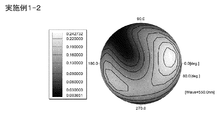
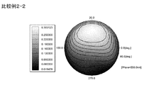
- FIG. 5 is a contour diagram showing a simulation result in the configuration of FIG. 5 of the image display device of the present invention.
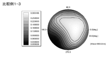
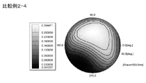
- FIG. 5 is a contour diagram showing a simulation result in the configuration of FIG. 6 of the image display device of the present invention.
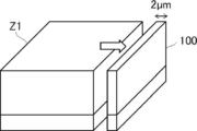
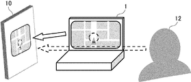
- It is a conceptual diagram which shows the information display device for a vehicle of this invention. It is a conceptual diagram for demonstrating the control method of the tilt angle of a liquid crystal curing layer. It is a conceptual diagram for demonstrating the control method of the tilt angle of a liquid crystal curing layer.
- FIG. 5 is a contour diagram showing a simulation result in the configuration of FIG. 17 of the image display device of the present invention.
- FIG. 5 is a contour diagram showing a simulation result in the configuration of FIG. 18 of the image display device of the present invention. It is a figure for demonstrating the method of measuring a tilt angle.
- the numerical range represented by using “-" in the present specification means a range including the numerical values before and after "-" as the lower limit value and the upper limit value.
- Re ( ⁇ ) and Rth ( ⁇ ) are in-plane phase difference (in-plane retardation) (nm) at wavelength ⁇ and retardation (nm) in the thickness direction, respectively. ..
- Re ( ⁇ ) is measured in AxoScan of Axometrics Co., Ltd. by incident light having a wavelength of ⁇ nm in the normal direction of the film.
- Rth ( ⁇ ) is calculated by the following method.
- the wavelength selection filter can be replaced manually, or the measured value can be converted by a program or the like for measurement.
- Rth ( ⁇ ) uses Re ( ⁇ ) as the in-plane slow axis (determined by AxoScan) as the tilt axis (rotation axis) (in the absence of the slow axis, it rotates in any direction in the film plane).
- a total of 7 points were measured by injecting light with a wavelength of ⁇ nm from each inclined direction in steps of 10 degrees from the normal direction to 60 degrees on one side with respect to the film normal direction (as the axis), and the measured retardation was measured. It is calculated by AxoScan based on the value, the assumed value of the average refractive index, and the input film thickness value.
- the retardation at an inclination angle larger than the inclination angle is calculated by AxoScan after changing its sign to negative.
- the retardation value is measured from two arbitrary inclined directions with the slow axis as the inclined axis (rotating axis) (when there is no slow axis, the arbitrary direction in the film surface is used as the rotating axis).
- the Rth can be calculated from the following equations (I) and (II) based on the value, the assumed value of the average refractive index, and the input film thickness value.
- Re ( ⁇ ) represents the retardation value in the direction inclined by the angle ⁇ from the normal direction.
- nx represents the refractive index in the slow axis direction in the plane
- ny represents the refractive index in the direction orthogonal to nx in the plane
- nz represents the refractive index in the direction orthogonal to nx and ny
- d represents the film thickness.
- Rth ( ⁇ ) is calculated by the following method.
- Rth ( ⁇ ) steps Re ( ⁇ ) 10 degrees from -60 degrees to +60 degrees with respect to the film normal direction with the in-plane slow axis (determined by AxoScan) as the tilt axis (rotation axis).
- Measured at 13 points by injecting light with a wavelength of ⁇ nm from each of the inclined directions, and calculated by AxoScan based on the measured retardation value, the assumed value of the average refractive index, and the input film thickness value.
- the film has reverse wavelength dispersibility as Re (450) / Re (550) ⁇ 1.0 and Re (650) / Re (550)> 1.0, or Rth (450) / Rth ( 550) Refers to the case where at least one of ⁇ 1.0 and Rth (650) / Rth (550)> 1.0 is satisfied.
- Re (450) / Re (550) ⁇ 1.0 and Re (650) / Re (550) ⁇ 1.0, or Rth (450) / Rth (550) ⁇ 1.0 and Rth (650) / Rth When any of (550) ⁇ 1.0 is satisfied, the forward wavelength dispersibility is used.
- the material having negative birefringence means that the refractive index ellipsoid peculiar to the material has a disk shape.
- the material having positive birefringence represents a material in which the refractive index ellipsoid peculiar to the material is rod-shaped.
- the optical axis (optic axis) of the refractive index ellipsoid is the same as the axis of symmetry, and is the normal direction of the disk surface for materials with negative birefringence and the major axis direction for materials with positive birefringence. Is.
- the first aspect of the optical film of the present invention is Including at least an optically anisotropic layer and a polarizer,
- the optically anisotropic layer is optically uniaxially anisotropic, and when viewed from the optically anisotropic layer side, the optical axis and the polarizer when the optical axis of the optically anisotropic layer is projected onto the polarizer
- the angle formed by the absorption axis of is + 50 ° to + 70 ° or -50 ° to -70 °.
- the average tilt angle of the optical axis with respect to the main surface of the optically anisotropic layer is 20 ° to 45 °.
- the first aspect of the optical film of the present invention is Including at least an optically anisotropic layer and a polarizer
- the optically anisotropic layer is an optically anisotropic body in which optically anisotropic bodies having optically positive birefractive properties are hybrid-oriented, and is delayed in the optically anisotropic layer when viewed from the optically anisotropic layer side.
- the angle formed by the slow axis and the absorber's absorption axis is + 50 ° to + 70 ° or -50 ° to -70 °.
- the average tilt angle with respect to the main surface of the optically anisotropic layer on the slow axis is 20 ° to 45 °.
- the first C aspect of the optical film of the present invention is Including at least an optically anisotropic layer and a polarizer
- the optically anisotropic layer is an optically anisotropic body in which optically anisotropic bodies having an optically negative double refractive property are hybrid-oriented, and the advance of the optically anisotropic layer when viewed from the optically anisotropic layer side.
- the angle formed by the phase advance axis and the absorber absorption axis is + 50 ° to + 70 ° or -50 ° to -70 °.
- the average tilt angle of the phase advance axis with respect to the main surface of the optically anisotropic layer is 20 ° to 45 °.
- the second aspect of the optical film of the present invention is Including at least an optically anisotropic layer and a polarizer
- the optically anisotropic layer is optically uniaxially anisotropic, and when viewed from the optically anisotropic layer side, the optical axis and the polarizer when the optical axis of the optically anisotropic layer is projected onto the polarizer
- the angle formed by the transmission axis of is + 50 ° to + 70 ° or -50 ° to -70 °.
- the average tilt angle of the optical axis with respect to the main surface of the optically anisotropic layer is 20 ° to 45 °.
- the second aspect of the optical film of the present invention is Including at least an optically anisotropic layer and a polarizer
- the optically anisotropic layer is an optically anisotropic body in which optically anisotropic bodies having optically positive birefractive properties are hybrid-oriented, and is delayed in the optically anisotropic layer when viewed from the optically anisotropic layer side.
- the angle formed by the slow axis and the transmission axis of the polarizer is + 50 ° to + 70 ° or -50 ° to -70 °.
- the average tilt angle with respect to the main surface of the optically anisotropic layer on the slow axis is 20 ° to 45 °.
- a second aspect of the optical film of the present invention is Including at least an optically anisotropic layer and a polarizer
- the optically anisotropic layer is an optically anisotropic body in which optically anisotropic bodies having an optically negative double refractive property are hybrid-oriented, and the advance of the optically anisotropic layer when viewed from the optically anisotropic layer side.
- the angle formed by the phase advance axis and the transmission axis of the polarizer is + 50 ° to + 70 ° or -50 ° to -70 °.
- the average tilt angle of the phase advance axis with respect to the main surface of the optically anisotropic layer is 20 ° to 45 °.
- All of the optical films of the first aspect A aspect to the second aspect C aspect of the present invention are used by being arranged between the back light side polarizing plate and the backlight in the image display device (liquid crystal display device). At that time, the optical film is arranged so that the absorption axis of the polarizing plate on the backlight side and the absorption axis of the polarizer are parallel or orthogonal to each other. As a result, the configuration of the image display device of the present invention can be obtained.
- the optical films of the first aspect A to the first aspect C are collectively referred to as the optical film of the first aspect.
- the optical films of the second aspect A to the second aspect C are collectively referred to as the optical film of the second aspect.
- the angle formed by the optical axis of the optically anisotropic layer and the absorption axis of the polarizer is + 50 ° to + 70 ° or ⁇ 50 ° to ⁇ 70 °, whereas it is ⁇ 50 ° to ⁇ 70 °.
- the angle formed by the optical axis of the optically anisotropic layer and the transmission axis of the polarizer is + 50 ° to + 70 °, or ⁇ 50 ° to ⁇ 70 °.
- the absorption axis of the polarizer is the absorption axis of the backlight side polarizing plate.
- An image display device having the following configuration can be obtained by arranging it so as to be parallel to.
- the transmission axis of the polarizer is the absorption axis of the polarizing plate on the backlight side.
- An image display device having the following configuration can be obtained by arranging it parallel to, that is, arranging the absorption axis of the polarizer to be orthogonal to the absorption axis of the polarizing plate on the backlight side.
- the absorption axis of the polarizing element is the polarizing plate on the backlight side.
- the transmission axis of the polarizer is the absorption axis of the polarizing plate on the backlight side.
- an image display device having the following configuration can be obtained.
- the main surface is the maximum surface of a sheet-like object (plate-like object, film, etc.).
- the optical film will also be described by describing the image display device having the optical film.
- the first aspect of the image display device of the present invention is An image display device including a viewing side polarizing plate, a liquid crystal cell, a backlight side polarizing plate, an optical film, and a backlight in this order.
- the optical film contains an optically anisotropic layer and a polarizer in this order from the liquid crystal cell side.
- the absorption axis of the backlit side polarizing plate and the absorption axis of the polarizer are parallel or orthogonal.
- the optically anisotropic layer is optically uniaxially anisotropic, and the orientation of the optical axis when the optical axis of the optically anisotropic layer is projected onto the first polarizer when viewed from the visual side of the image display device.
- the angle is + 50 ° to + 70 ° or -50 ° to -70 ° with respect to the horizontal direction.
- the average tilt angle of the optical axis with respect to the main surface of the optically anisotropic layer is 20 ° to 45 °.
- the first aspect of the image display device of the present invention is An image display device including a viewing side polarizing plate, a liquid crystal cell, a backlight side polarizing plate, an optical film, and a backlight in this order.
- the optical film contains an optically anisotropic layer and a polarizer in this order from the liquid crystal cell side.
- the absorption axis of the backlit side polarizing plate and the absorption axis of the polarizer are parallel or orthogonal.
- the optically anisotropic layer is an optically anisotropic layer in which optically anisotropic bodies having positive birefringence are hybrid-oriented, and polarizes the slow axis of the optically anisotropic layer when viewed from the visual side of an image display device.
- the optics of the slow axis when projected onto the child is + 50 ° to + 70 ° or -50 ° to -70 ° with respect to the horizontal direction.
- the average tilt angle with respect to the main surface of the optically anisotropic layer on the slow axis is 20 ° to 45 °.
- This is an image display device in which the in-plane retardation Re (550) of the optically anisotropic layer at a wavelength of 550 nm is 70 nm to 240 nm.
- a first aspect of the image display device of the present invention is An image display device including a viewing side polarizing plate, a liquid crystal cell, a backlight side polarizing plate, an optical film, and a backlight in this order.
- the optical film contains an optically anisotropic layer and a polarizer in this order from the liquid crystal cell side.
- the absorption axis of the backlit side polarizing plate and the absorption axis of the polarizer are parallel or orthogonal.
- the optically anisotropic layer is an optically anisotropic layer in which optically anisotropic bodies having negative birefringence are hybrid-oriented, and the phase-advancing axis of the optically anisotropic layer is polarized when viewed from the visual side of an image display device.
- the optics of the phase-advancing axis when projected onto the child is + 50 ° to + 70 ° or -50 ° to -70 ° with respect to the horizontal direction.
- the average tilt angle of the phase advance axis with respect to the main surface of the optically anisotropic layer is 20 ° to 45 °.
- This is an image display device in which the in-plane retardation Re (550) of the optically anisotropic layer at a wavelength of 550 nm is 70 nm to 240 nm.
- the image display devices of the first aspect A to the first aspect C are collectively referred to as the image display device of the first aspect.
- a liquid crystal display device can be used as a preferred aspect of the image display device according to the first aspect of the present invention.
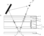
- a more specific embodiment of the image display device according to the first aspect of the present invention is shown in FIG. 1 .
- the image display device 1 shown in FIG. 1 includes a viewing side polarizing plate 2, a liquid crystal cell 3, a backlight side polarizing plate 5, an optical film 4, and a backlight 8 in this order.
- the optical film 4 includes an optically anisotropic layer 6 and a polarizer 7 in this order from the liquid crystal cell 3 side.
- each member is arranged so that its main surface is parallel to each other.
- Each polarizing plate (polarizer) may include a polarizing plate protective film (not shown).
- the arrow of the viewing side polarizing plate 2 indicates that the absorption axis of the viewing side polarizing plate 2 is parallel to the paper surface
- the symbol of the backlight side polarizing plate 5 indicates the absorption axis of the backlight side polarizing plate 5.
- Indicates that is perpendicular to the paper surface, and the symbol of the polarizer 7 indicates that the absorption axis of the polarizer is perpendicular to the paper surface. That is, in the example shown in FIG. 1, the absorption axis of the backlit side polarizing plate 5 and the absorption axis of the polarizer 7 of the optical film 4 are parallel.
- the optically anisotropic layer 6 is optically uniaxially anisotropic and is optically anisotropic when viewed from the visual side of the image display device 1.
- the optic angle of the optical axis is + 50 ° to + 70 ° or -50 ° to -70 ° with respect to the horizontal direction
- the optics of the optical axis The average tilt angle of the anisotropic layer 6 with respect to the main surface is 20 ° to 45 °
- the in-plane retardation Re (550) of the optically anisotropic layer 6 at a wavelength of 550 nm is 70 nm to 240 nm.
- the optically anisotropic layer 6 is an optically anisotropic layer in which optically anisotropic bodies having positive birefractive properties are hybrid-oriented, and is described in the image display device 1.
- the azimuth angle of the slow axis is + 50 ° to + 70 ° or -50 ° to the horizontal direction.
- the average tilt angle with respect to the main surface of the optically anisotropic layer 6 on the slow axis is 20 ° to 45 °
- the in-plane retardation Re (550) of the optically anisotropic layer 6 at a wavelength of 550 nm. ) Is 70 nm to 240 nm.
- the optically anisotropic layer 6 is an optically anisotropic layer in which optically anisotropic substances having negative double refractive properties are hybrid-oriented, and is described in the image display device 1.
- the azimuth angle of the phase-advancing axis is + 50 ° to + 70 ° or -50 ° to the horizontal direction.
- the average tilt angle of the phase-advancing axis with respect to the main surface of the optically anisotropic layer 6 is 20 ° to 45 °
- the in-plane retardation Re (550) of the optically anisotropic layer 6 at a wavelength of 550 nm. ) Is 70 nm to 240 nm.
- the optically anisotropic layer 6 which is uniaxial anisotropy in the image display device of the first A aspect.
- the optical axis of can be read as the slow axis of the hybrid-oriented optically anisotropic layer 6.
- the optical axis of the optically anisotropic layer 6 which is uniaxially anisotropic in the image display device of the first A aspect is hybrid-oriented with respect to the phase advance axis of the optically anisotropic layer 6. Can be read as.
- the optically anisotropic layer 6 has such a configuration, so that the image (video) displayed by the image display device can be imparted with asymmetry in the left-right direction. it can. As a result, a clear image can be displayed to the driver, and an appropriate viewing angle control function that reduces reflection on the window glass can be exhibited. In addition, it is possible to suppress the occurrence of moire in the displayed image. Therefore, the optical film 4 can be said to be a viewing angle control film. Further, since the optical film 4 having the optically anisotropic layer 6 and the polarizer 7 is only added to the image display device (liquid crystal display device) having a general configuration, the thickness can be reduced. Cost can be suppressed. The configuration of such an optically anisotropic layer and the operation of the image display device will be described in detail later.
- the image display device may have other members, if necessary.
- the image display device may have a configuration in which an optical compensation film is arranged between the liquid crystal cell and the polarizing plate.
- the image display device may have an adhesive layer for sticking each member to each other.
- liquid crystal cell a liquid crystal cell having various display modes known conventionally can be used.
- the display modes of the liquid crystal cells include TN (Twisted Nematic), IPS (In-Plane Switching), FLC (Ferroelectric Liquid Crystal), AFLC (Anti-ferroelectric Liquid Crystal), OCB (Optical)
- Various display modes are available, such as (VerticallyIndexed), ECB (Electricularly Controlled Birefringence), and HAN (HybridIndexed Nematic).
- a display mode in which the above display mode is oriented and divided can also be used.
- the optical film of the present invention is effective in an image display device using a liquid crystal cell in any display mode.
- the image display device of the present invention may be a transmissive type, a reflective type, or a semitransparent type, but the transmissive type is preferable because the display contrast can be easily stabilized.
- the liquid crystal cell is formed by supporting a liquid crystal between two substrates having an electrode layer.
- the electrode layer is a transparent electrode layer.
- the liquid crystal layer of a liquid crystal cell is usually formed by enclosing a liquid crystal in a space formed by sandwiching a spacer between two substrates.
- the transparent electrode layer is formed on at least one or both of the two substrates as a transparent film containing a conductive substance.
- the liquid crystal cell may be further provided with a gas barrier layer, a hard coat layer, or an undercoat layer (undercoat layer) (used for adhering the transparent electrode layer). These layers are usually provided on the substrate.
- the substrate of the liquid crystal cell generally has a thickness of 50 ⁇ m to 2 mm.
- the transmissive TN mode, IPS or FFS mode, and VA mode are preferable from the viewpoint of display responsiveness, and the IPS or FFS mode is particularly preferable from the viewpoint of easy viewing angle design.
- the viewing-side polarizing plate and the backlight-side polarizing plate have basically the same configuration except that the arrangement is different, they will be collectively referred to as a polarizing plate in the following description.
- a polarizing plate a conventionally known linear polarizing plate used in a liquid crystal display device or the like can be appropriately used.
- a polarizing plate a polarizing plate in which a (linear) polarizing element described below is laminated with a polarizing plate protective film is used, if necessary. The same applies to the viewing side polarizing plate 2 and the backlight side polarizing plate 5.
- the relative arrangement of the transmission axes of the viewing side polarizing plate 2 and the backlight side polarizing plate 5 can be arranged according to the display mode of the liquid crystal display device used and the normally black mode or the normally white mode, and can be arranged with each other. It may be a so-called cross Nicol arrangement in which the transmission axes of the above are orthogonal (for example, FIG. 1), or a so-called Paranicol arrangement in which the transmission axes are parallel to each other.
- polarizing elements known ones can be used without limitation.
- a polyene-based polarizing element a polarizer made of a lyotropic liquid crystal compound having light absorption anisotropy, a polarizer in which a host liquid crystal is oriented with a dichroic dye as a guest, and the like.
- a wire grid polarizer and a reflective polarizer made of a stretched multilayer film of a polymer, or a reflective polarizer obtained by combining a cholesteric liquid crystal film and a ⁇ / 4 plate may be used.
- the polarizing plate can include a polarizing plate protective film, and it is possible to impart the strength and independence of the polarizing plate, suppress deterioration due to moisture, heat, etc., and improve the adhesiveness with other members. Yes (not shown in FIG. 1).
- Known polarizing plate protective films can be used without limitation, and plastic films such as polyester such as polyethylene terephthalate (PET), polycarbonate, acrylic resin, epoxy resin, polyurethane, polyamide, polyolefin, cycloolefin resin, cellulose derivative, and silicone. Can be mentioned.
- acrylic resin, polycarbonate resin, cellulose derivative (particularly triacetyl cellulose) and cycloolefin resin are preferable, and when isotropic is required, acrylic resin, cellulose derivative (particularly triacetyl cellulose) and cycloolefin resin Is preferable.
- polyethylene terephthalate, an acrylic resin, and a cellulose derivative (particularly triacetyl cellulose) are preferable if strength is required for use on the visible side surface of the visible side polarizing plate or the backlight side surface of the backlight side polarizing plate.
- the base material used for the optically anisotropic layer described later is incorporated into the polarizing plate, the base material may also function as a polarizing plate protective film.
- the image display device may have an adhesive layer, a cushion layer, a barrier layer, a hard coat layer, an easy adhesive layer and the like as other layers.
- the image display device may have an optical compensation film between the liquid crystal cell and the viewing side polarizing plate and / or the backlight side polarizing plate.
- the optical compensation film is provided to improve the viewing angle characteristics peculiar to the liquid crystal cell, and as a material that can be used, various polymer films and liquid crystal materials described in the optically anisotropic layer described later can be used. .. Further, the optical design can be appropriately designed with reference to known techniques.
- a backlight is a lighting device that irradiates light toward a liquid crystal cell.
- a conventionally known backlight used in a liquid crystal display device can be appropriately used.
- the backlight for example, a direct type backlight in which a plurality of light sources are arranged on the back surface side (opposite side of the liquid crystal cell) of the backlight side polarizing plate, and a light source facing the side surface of the plate-shaped light guide plate. Examples thereof include a side light type backlight that is arranged to guide the light emitted by the light source in the light guide plate and emits planar light from the main surface of the light guide plate.
- the backlight may have an optical film such as a diffusion sheet and a condensing sheet in order to adjust the brightness distribution of the emitted light.
- the light source is not particularly limited, and various light sources used in liquid crystal display devices such as LEDs (light emitting diodes) and cold cathode tubes can be appropriately used.
- the optical film 4 has an optically anisotropic layer 6 and a polarizer 7.
- the optical film 4 is arranged between the backlight side polarizing plate 5 and the backlight 8. Further, the optical film 4 is arranged in the order of the optically anisotropic layer 6 and the polarizer 7 from the liquid crystal cell 3 side. Therefore, the image display device 1 is arranged in the order of the viewing side polarizing plate 2, the liquid crystal cell 3, the backlight side polarizing plate 5, the optically anisotropic layer 6, the polarizer 7, and the backlight 8 from the viewing side. ..
- the optically anisotropic layer 6 is optically uniaxially anisotropic, and the optical axis of the optically anisotropic layer 6 when viewed from the visual side of the image display device 1.
- the azimuth angle of the optical axis is + 50 ° to + 70 ° or -50 ° to ⁇ 70 ° with respect to the horizontal direction when the optical axis is projected onto the polarizer 7, and the optically anisotropic layer 6 of the optical axis
- the average tilt angle with respect to the main surface is 20 ° to 45 °
- the in-plane retardation Re (550) of the optically anisotropic layer 6 at a wavelength of 550 nm is 70 nm to 240 nm.
- the absorption axis of the polarizer 7 is parallel to the absorption axis of the backlight side polarizing plate 5.
- optically uniaxial anisotropy means that the refractive index ellipsoid is a spheroid.
- the spheroid is a spheroid obtained by using an ellipse as its major axis or a minor axis as its axis of rotation.
- the spheroid obtained by rotating around the minor axis is also called an oblate spheroid, and corresponds to the refractive index ellipsoid of a material having negative birefringence.
- a spheroid obtained by rotating around a long axis is also called a prolate spheroid, and corresponds to a refractive index ellipsoid of a material having positive birefringence.
- the refractive index in the rotation axis direction is defined as the abnormal optical refractive index (ne)
- the refractive index in the direction perpendicular to the rotation axis is defined as the refractive index. Is called an isotropy refractive index (no).
- the direction of the optical axis of the optically anisotropic layer is defined as the direction of the abnormal light refractive index (ne).
- the refractive index ellipsoid E 1 of the disc-shaped liquid crystal compound is a flat sphere and is refracted.
- the optical axis P 1 is defined in the direction parallel to the minor axis of the index ellipsoid E 1.
- the direction of the optic axis of the disk-shaped liquid crystal compound is the normal direction with respect to the disk surface of the molecule.
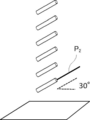
- the refractive index ellipsoid E 2 of the disk-shaped liquid crystal compound is a long sphere and is refracted, as shown in FIG.
- the optical axis P 2 is defined in the direction parallel to the long axis of the index ellipsoid E 2.
- the direction of the optic axis of the rod-shaped liquid crystal compound is the long axis direction of the molecule.
- Hybrid orientation refers to the tilt angle of the optical axis in the uniaxiallyotropic optically anisotropic layer, the tilt angle of the slow axis in the optically anisotropic layer having positive birefringence, and negative birefringence. This is an orientation in which the tilt angle of the phase-advancing axis in the optically anisotropic layer has continuously changes along the thickness direction of the optically anisotropic layer.
- the azimuth angle and tilt angle of the optical axis are defined as follows. First, the image display device is installed in the direction in which it is normally used, the stacking direction of each member in the image display device is the Z axis, the viewing side is positive, the backlight side is negative, and the horizontal direction is X when viewed from the viewing side.
- a coordinate system is defined in which the right direction is positive and the left direction is negative, the vertical direction is the Y axis when viewed from the visual side, the upward direction is positive, and the downward direction is negative.
- the azimuth angle has the optical axis of the uniaxial anisotropic substance, the slow axis of the optically anisotropic substance having positive birefringence, or the negative birefringence in the optically anisotropic layer when viewed from the visual side.
- This is the angle with respect to the horizontal direction when the phase-advancing axis of the optically anisotropic substance is projected onto the polarizer. That is, in FIG. 2, the optical axis P 1 is projected onto the XY plane, and the angle ⁇ formed by the projection line of the optical axis P 1 and the X axis is the azimuth angle. Further, in FIG.
- the optical axis P 2 is projected onto the XY plane, and the angle ⁇ formed by the projection line of the optical axis P 2 and the X axis is the azimuth angle.
- the azimuth angle of the optical axis is represented in the range of + 90 ° to ⁇ 90 °, and the angle rotated counterclockwise from the X axis is positive, and the angle rotated clockwise is negative.
- the azimuth has a positive angle in a form in which the optic axis rises on the positive side in the X and Y directions and a form in which the optic axis rises on the negative side in the X and Y directions.
- the azimuth has a negative angle when the optic axis rises to the negative side in the Y direction on the positive side in the X direction and when the optic axis rises to the positive side in the Y direction on the negative side in the X direction.
- the tilt angle is the optical axis of the uniaxial anisotropy in the optically anisotropic layer, the slow axis of the optically anisotropic substance having positive birefringence, or the optically anisotropic substance having negative birefringence.
- the angle of the optical axis with respect to the main surface of the phase-advancing axis that is, in FIG. 2, the angle ⁇ formed by the XY plane and the optic axis is the tilt angle. Similarly, in FIG. 3, the angle ⁇ formed by the XY plane and the optic axis is the tilt angle.
- the tilt angle becomes a certain value in the thickness direction of the layer, but in the case of hybrid orientation, the tilt angle of the optical axis in the uniaxial anisotropy optically anisotropic layer is positive.
- the tilt angle of the slow axis in the optically anisotropic layer having birefringence and the tilt angle of the phase advance axis in the optically anisotropic layer having negative birefringence are continuous along the thickness direction of the support. It changes in a targeted manner.
- the tilt angle is the average value of the tilt angles on the viewing side surface and the backride side surface of the optically anisotropic layer, and this is taken as the average tilt angle.
- the image display device 1 shown in FIG. 4 has the same configuration as the image display device 1 shown in FIG.
- the image display device 1 shown in FIG. 4 when light is emitted from the backlight 8, the light becomes linearly polarized light that vibrates in a direction parallel to the paper surface when passing through the polarizer 7.
- the linearly polarized light that has passed through the polarizer 7 is incident on the optically anisotropic layer 6.
- the optically anisotropic layer 6 since the optically anisotropic layer 6 has the optical axis as described above, the phase difference given to the light differs depending on the angle of incidence (polar angle, azimuth) on the optically anisotropic layer 6. It becomes.
- the traveling direction of the light I 1 (see FIG. 4) emitted from the backlight 8 in an oblique direction is close to parallel to the optical axis of the optically anisotropic layer 6 which is a uniaxial anisotropy.
- the light I 1 is almost not given a phase difference from the optically anisotropic layer 6, and is transmitted through the optically anisotropic layer 6 with linearly polarized light vibrating in a direction parallel to the paper surface.
- the light I 1 transmitted through the optically anisotropic layer 6 is incident on the backlit side polarizing plate 5.
- the absorption axis of the backlight side polarizing plate 5 Since the absorption axis of the backlight side polarizing plate 5 is perpendicular to the paper surface, most of the light I 1 which is linearly polarized light in the direction parallel to the paper surface is not absorbed by the backlight side polarizing plate 5 and is backed up. It transmits through the light side polarizing plate 5.
- the light I 1 that has passed through the backlit-side polarizing plate 5 enters the liquid crystal cell 3 and the viewing-side polarizing plate 2, and is transmitted or shielded depending on the on / off state of the liquid crystal cell 3. As a result, the image is displayed. Therefore, the image can be displayed to the observer 12 who sees the image display device 1 from this direction.
- the light I 2 emitted in a direction different from that of the light I 1 , that is, in a direction not parallel to the optical axis of the optically anisotropic layer 6, is given a phase difference by the optically anisotropic layer 6.
- a phase difference of ⁇ / 2 is given to the obliquely incident light I 2 and also.
- the light I 2 is converted by the optically anisotropic layer 6 from linearly polarized light that oscillates in a direction parallel to the paper surface to linearly polarized light that oscillates in a direction perpendicular to the paper surface. Since the absorption axis of the backlight-side polarizing plate 5 is perpendicular to the paper surface, the light I 2 that has passed through the optically anisotropic layer 6 is absorbed by the backlight-side polarizing plate 5. Therefore, the light I 2 does not pass through the backlight side polarizing plate 5, and the amount of light incident on the liquid crystal cell 3 and the viewing side polarizing plate 2 is reduced. That is, the amount of light in the displayed image is reduced.
- the optically anisotropic substance is a uniaxial body, but it can be considered that the same phenomenon occurs even when the optically anisotropic substance is a hybrid-oriented optically anisotropic substance.
- the side mirrors and rearview mirrors of the automobile are replaced with an image display device, and the image display device covers the vehicle body structures such as side pillars that obstruct the driver's view and displays an image that complements the obstructed view. It is proposed to do.
- the image display device When the image display device is incorporated in the vehicle in this way, the driver and the image display device may not always be arranged so as to face each other due to the structural design of the vehicle. Therefore, the image display device needs to have a wide viewing angle so that both color and brightness can be correctly displayed even from various angles (extreme angle, azimuth angle).
- the viewing angle is widened, it is designed so as not to depend on the polar angle or the azimuth angle.
- louver film or an electro-optical element it is conceivable to apply a louver film or an electro-optical element in order to prevent such a display image from being reflected.
- the conventional louver film has symmetry in the left-right or vertical direction, there is a problem that it is difficult to both display a clear image to the driver and reduce the reflection on the window glass.
- the electro-optical element has a problem that the thickness of the device increases, it is difficult to mount the electro-optical element in a limited space in the vehicle, and the manufacturing cost also increases.
- the azimuth angle and average tilt angle of the optical axis of the optically anisotropic layer and the in-plane phase difference Re (550) are set within the above ranges.
- the polarization state of the light incident on the liquid crystal cell can be made dependent on the polar angle and the azimuth angle.
- a visual field region visible region in which light that has passed through the optically anisotropic layer 6 and is incident on the backlight-side polarizing plate 5 is transmitted without being mostly absorbed by the backlight-side polarizing plate 5 is formed.
- a visual field region that is absorbed by the backlight-side polarizing plate 5 and reduces the amount of transmitted light can be provided asymmetrically. Therefore, by arranging the image display device of the present invention so that the visible region faces the observer and the other region faces the reflector 10 such as the windshield, the reflection on the reflector 10 can be achieved. It can be suppressed and a clear display can be given to the observer 12.
- the light beam before being incident on the liquid crystal cell is provided with directivity.
- the thickness of the device can be reduced. As a result, it is possible to control the viewing angle asymmetrically in the left-right direction without affecting the design even for vehicle applications.
- moire may occur between the members constituting the backlight and the pixels of the liquid crystal cell.
- the image display device of the present invention does not essentially have such a fine structure, moire does not occur.
- the visible region occurs in a direction parallel to the optical axis of the optically anisotropic layer. Therefore, the polar angle in the central direction of the visible region can be adjusted mainly by controlling the average tilt angle of the optical axis in the optically anisotropic layer.
- the average tilt angle, azimuth angle, and in-plane phase difference Re of the optical axis of the optically anisotropic layer may be appropriately set according to the direction of the visible region in the image display device.
- the viewing angle control function of the image display device of the present invention will be described in more detail using simulation.
- the simulation conditions are as follows.
- the disk-shaped liquid crystal compound is a uniaxial anisotropy having a uniform tilt orientation (O-plate) in which the disk surface of the disk-shaped liquid crystal compound has a tilt angle of 60 ° with respect to the main surface of the image display device.
- the optical axis of the disk-shaped liquid crystal compound is tilted at 30 ° with respect to the main surface of the optically anisotropic layer.
- the disk surface is tilted with the lower left side facing up with respect to the main surface of the image display device.
- the optical axis of the optically anisotropic layer viewed from the viewing side polarizing plate 2 side is 60 ° counterclockwise with respect to the horizontal direction, with respect to the absorption axis of the backlit side polarizing plate 5. It is 30 ° clockwise.
- the optically anisotropic layer is a liquid crystal cured layer formed by using a rod-shaped liquid crystal compound.
- the rod-shaped liquid crystal compound has uniaxial anisotropy due to a uniform tilt orientation (O-plate) in which the major axis direction of the rod-shaped liquid crystal compound (liquid crystal molecule) is a tilt angle of 30 ° from the main surface of the image display device. It is a body, that is, the optic axis is tilted at 30 ° with respect to the main surface of the optically anisotropic layer.
- the long axis of the liquid crystal molecules is tilted by 30 ° with the upper right side facing up with respect to the main surface of the image display device.
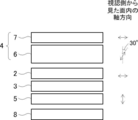
- the optical axis of the optically anisotropic layer viewed from the viewing side polarizing plate 2 side is 60 ° counterclockwise with respect to the horizontal direction, and is clockwise with respect to the absorption axis of the backlit side polarizing plate 5.
- the circumference is 30 °.
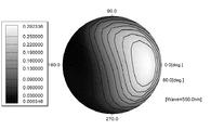
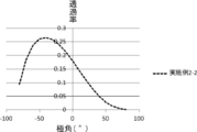
- FIG. 9 shows a change in display luminance from an azimuth angle of 0 ° to 180 ° and a polar angle of -80 ° to 80 ° in the configurations of FIGS. 5 and 6. Further, contour diagrams of the luminance distribution in each configuration of FIGS. 5 and 6 are shown in FIGS. 10 and 11. From FIGS. 9, 10 and 11, both the configuration of FIG. 5 and the configuration of FIG. 6 have a center in the visible region near an azimuth angle of 0 ° and a polar angle of 60 °, and the brightness is significantly reduced except in the visible region. You can see that.
- An image display device exhibiting such characteristics is arranged along the vehicle interior as shown in FIG. 12, and when displaying information that complements the field of view obstructed by the pillars and the body, the visible range is set to the driver 12 side.
- the visible region is provided on the right side of the image display device, but those skilled in the art can appropriately change the above-mentioned parameters and the arrangement of each member in order to provide the visible region in a desired direction, not limited to the right side. It is possible to do.
- the configuration is the same as that shown in FIG. 5, except that the absorption axis of the polarizer 7 of the optical film 4 is arranged so as to be orthogonal to the absorption axis of the backlit side polarizing plate 5.
- the visible region has a center in the vicinity of an azimuth angle of 180 ° and a polar angle of 60 °. That is, the azimuth angle of the visible region changes by 180 ° depending on whether the absorption axis of the polarizer 7 is parallel or orthogonal to the absorption axis of the backlight side polarizing plate 5.
- the azimuth angle of the optical axis of the optically anisotropic layer is an angle
- the tilt direction of the optical axis is opposite.
- the visible region has a center in the vicinity of an azimuth angle of 180 ° and a polar angle of 60 °. That is, even if the azimuth direction of the optical axis of the optically anisotropic layer is the same, the azimuth angle in the visible region changes by 180 ° depending on the tilt direction of the optical axis.
- the refractive index anisotropy in the optically anisotropic layer may be forward wavelength dispersion, but is preferably reverse wavelength dispersion.
- the refractive index anisotropy of the optically anisotropic layer is forward wavelength dispersion, it is displayed in a region where the display brightness gradually decreases depending on the display mode of the liquid crystal cell used and the design of the refractive index anisotropy. Coloring may be seen.
- This tinting can be made more neutral by adjusting the wavelength dispersibility of the optically anisotropic layer. That is, in the region where the display luminance is darkened, if there is a difference in the phase difference change at each wavelength, the transmittance for each wavelength is different and it is visually recognized as being tinted.
- the optically anisotropic layer reverse wavelength dispersive the phase difference change for each wavelength is uniform, the brightness is reduced while maintaining the neutral color, and only the reflection in a specific angular direction is performed. Can be suppressed.
- the refractive index anisotropy ⁇ n, the film thickness d, and Re ( ⁇ ) satisfy the relationships of the following equations (5), (6), and (7). Is desirable. 80 nm ⁇ n ⁇ d ⁇ 320 nm ⁇ ⁇ ⁇ (5) Re (450) / Re (550) ⁇ 1.0 ... (6) Re (650) / Re (550)> 1.0 ... (7)
- polyesters such as polyethylene terephthalate (PET), polycarbonates, acrylic resins, epoxy resins, polyurethanes, polyamides, polyolefins, cycloolefin resins, cellulose derivatives and
- PET polyethylene terephthalate
- acrylic resins epoxy resins
- polyurethanes polyamides
- polyolefins polyurethane resins
- cellulose derivatives cellulose derivatives
- An example thereof is a stretched film or a liquid crystal film having a liquid crystal cured film obtained by fixing the orientation of a liquid crystal composition containing a liquid crystal compound.
- a liquid crystal film having a liquid crystal cured film obtained by fixing the orientation of the liquid crystal composition is particularly preferable in that the above-mentioned optical axis can be easily realized.
- the liquid crystal film having a liquid crystal cured film obtained by fixing the orientation of the liquid crystal composition described above is preferably formed from a polymerizable liquid crystal composition containing a polymerizable liquid crystal compound.
- the liquid crystal compound may be a rod-shaped liquid crystal compound or a disk-shaped liquid crystal compound.
- the liquid crystal cured film obtained by fixing the orientation of the liquid crystal composition described above is formed by curing the polymerizable liquid crystal composition after making it into a desired orientation state.
- the polymerizable liquid crystal composition is applied directly to the base material or on the alignment treatment surface of the alignment film formed on the base material, oriented along the orientation treatment direction, and fixed in the orientation state.
- Known base materials can be used, and examples thereof include polyesters such as polyethylene terephthalate (PET), polycarbonates, acrylic resins, epoxy resins, polyurethanes, polyamides, polyolefins, cycloolefin resins, and cellulose derivatives.
- PET polyethylene terephthalate
- acrylic resins epoxy resins
- polyurethanes polyamides
- polyolefins polyamides
- polyolefins polyolefin resins
- cycloolefin resins cellulose derivatives.
- a rubbing-treated film of a layer containing an organic compound such as a polymer, an oblique vapor-deposited film of an inorganic compound, a film having microgrooves, or an organic substance such as ⁇ -tricosanoic acid, dioctadecylmethylammonium chloride, or methyl stearylate examples thereof include a membrane obtained by accumulating LB (Langmuir-Blodgett) membranes obtained by the Langmuir-Blodget method of a compound.
- LB Liangmuir-Blodgett
- a film formed by rubbing the surface of a layer (polymer layer) containing an organic compound such as a polymer can be preferably used.
- the rubbing treatment is carried out by rubbing the surface of the polymer layer with paper or cloth several times in a certain direction (preferably in the longitudinal direction of the support).
- the polymer used for forming the alignment film include polyimide, polyvinyl alcohol, modified polyvinyl alcohol described in paragraph numbers [0071] to [0995] of Japanese Patent No. 3907735, and polymerization described in JP-A-9-152509. It is preferable to use a polymer having a sex group or the like.
- photo-alignment film photo-alignment layer
- a photo-alignable material is irradiated with polarized light or non-polarized light to form an alignment layer.
- the thickness of the alignment film is not particularly limited as long as it can exhibit the alignment function, but is preferably 0.01 to 5 ⁇ m, and more preferably 0.05 to 2 ⁇ m.
- Examples of the photoalignment material used for the photoalignment film include JP-A-2006-285197, JP-A-2007-076839, JP-A-2007-138138, JP-A-2007-094071, and JP-A-2007-.
- Examples thereof include compounds capable of photodimerization, particularly synamate compounds, chalcone compounds, and coumarin compounds.
- Particularly preferred examples include azo compounds, photocrosslinkable polyimides, polyamides, esters, synnamate compounds, and chalcone compounds.
- the average tilt angle of the optically anisotropic layer in the thickness direction of the optical axis can be set to a desired angle by inclining the orientation of the liquid crystal compound.
- the liquid crystal compound may have a configuration in which the liquid crystal compound is uniformly inclined over the thickness direction, or at least a part of the liquid crystal compounds may be inclined or oriented.
- the liquid crystal compound may be fixed in a so-called hybrid orientation state. In the hybrid orientation, the angle between the optical axis of the liquid crystal compound and the layer surface increases or decreases as the distance from the alignment film surface increases in the depth direction of the layer. The angle preferably decreases with increasing distance from the alignment film surface.
- the change in angle can be a continuous increase, a continuous decrease, an intermittent increase, an intermittent decrease, a change including a continuous increase and a continuous decrease, or an intermittent change including an increase and a decrease.
- the intermittent change includes a region where the angle does not change in the middle of the thickness direction.
- the term "hybrid orientation" includes a region in which the angle does not change, but also includes an orientation state in which the angle is increasing or decreasing as a whole.
- the optically anisotropic layer may have one or more liquid crystal curing layers described above, or may have two or more layers.
- the liquid crystal compound has a uniformly oriented liquid crystal cured layer that is uniformly inclined in the film thickness direction and a hybrid oriented liquid crystal cured layer. It may have a structure having layers, or may have a structure having a plurality of layers of hybrid-oriented liquid crystal cured layers.
- an optically anisotropic layer in which the liquid crystal compound is uniformly inclined in the thickness direction in the layer
- a means for independently controlling the tilt angle on the support side and the tilt angle on the air interface side. is required.
- a hybrid orientation is performed between the liquid crystal curing layer 24 (O plate) and the support 20 for uniformly tilting the liquid crystal compound 23.
- the liquid crystal layer 22 is separately provided, and the tilt angle of the liquid crystal curing layer 24 on the support 20 side is controlled by using the tilt angle of the air side interface of the liquid crystal layer 22.
- An idea of using the liquid crystal layer 22 having the hybrid orientation fixed in this way as an alignment film and controlling the orientation direction of another liquid crystal layer coated on the liquid crystal layer 22 is described in Japanese Patent No. 3969637 and the like.
- the tilt angle of the liquid crystal compound 23 on the air interface side of the liquid crystal cured layer 24 has a property of being oriented in the vertical direction due to the exclusion volume effect unless otherwise specified. That is, the optical axis of the disk-shaped liquid crystal compound wants to be oriented in the horizontal direction, and the optical axis of the rod-shaped liquid crystal compound wants to be oriented in the vertical direction. Therefore, it is difficult to fix the tilt angle of the liquid crystal compound 23 on the air interface side at an arbitrary angle.
- the tilt angle of the liquid crystal compound 23 on the air interface side can be controlled at an arbitrary angle as shown in FIG.
- the liquid crystal cured layer 24 (O plate) formed on the support 20 by the above method is transferred and used as an optical film (viewing angle control film), the support 20 (TAC film or the like) and / or If the hybrid-oriented liquid crystal layer 22 remains, unfavorable phenomena such as coloring when observed from an angle, left and right viewing angle adjustment performance, and thick film may occur. Therefore, as described above, when the liquid crystal cured layer 24 is formed by using the hybrid-oriented liquid crystal layer 22 as the alignment film, the liquid crystal cured layer 24 (O plate) and the liquid crystal layer 22 can be peeled off at the interface. Therefore, by using the liquid crystal curing layer 24 alone as an optically anisotropic layer, the performance can be further improved.
- both the liquid crystal curing layer 24 (O plate) and the liquid crystal layer 22 are liquid crystal compounds having similar properties, the adhesion tends to be high and peeling at the interface is difficult, but the liquid crystal layer.
- the amount of residual oxygen when the 22 is cured by ultraviolet rays to 100 ppm or less, the amount of residual double bonds on the surface is reduced, and interfacial peeling becomes possible.
- a layer (O plate) having optical anisotropy in which the liquid crystal compound is uniformly inclined in the thickness direction in the layer, which is most preferable in terms of performance in the application of the present application, is taken as an example.
- a liquid crystal cured layer in which the tilt angle of the liquid crystal compound is variously changed from the air interface side to the support interface side and hybrid-oriented is produced, and the liquid crystal cured layer and the liquid crystal layer 22 are combined with each other. Only the liquid crystal cured layer may be used as the optically anisotropic layer by peeling the interface between the two.
- the rod-shaped liquid crystal compound include azomethines, azoxys, cyanobiphenyls, cyanophenyl esters, benzoic acid esters, cyclohexanecarboxylic acid phenyl esters, cyanophenylcyclohexanes, cyano-substituted phenylpyrimidines, alkoxy-substituted phenylpyrimidines, and the like.
- Phenyldioxans, trans and alkenylcyclohexylbenzonitriles are preferably used.
- These rod-shaped liquid crystal compounds are fixed by introducing a polymerizable group into the terminal structure of the rod-shaped liquid crystal compound (similar to the disk-shaped liquid crystal described later), and utilizing this polymerization and curing reaction.
- a polymerizable nematic rod-shaped liquid crystal compound is cured by ultraviolet rays is described in JP-A-2006-209073.
- not only the above-mentioned low molecular weight liquid crystal compound but also high molecular weight liquid crystal compound can be used.
- the high molecular weight liquid crystal compound is a polymer having a side chain corresponding to the above low molecular weight liquid crystal compound.
- An optically anisotropic layer using a polymer liquid crystal compound is described in JP-A-5-053016 and the like.
- a compound having a refractive index anisotropy of opposite wavelength dispersibility can be used as the rod-shaped liquid crystal compound.
- the fact that the refractive index anisotropy of the compound is inverse wavelength dispersibility means that the refractive index anisotropy ⁇ n of the molecule increases with wavelength.
- a compound having a reverse wavelength dispersibility has a refractive index anisotropy ⁇ n ( ⁇ ) when the compound is uniaxially oriented. ⁇ n (450) / ⁇ n (550) ⁇ 1.0 ⁇ n (650) / ⁇ n (550)> 1.0 It can also be said that it satisfies.
- the decrease of the refractive index anisotropy ⁇ n of the molecule according to the wavelength is called forward wavelength dispersibility.
- Examples of such a reverse wavelength dispersible compound include JP-A-2009-173893, JP-A-2010-030979, JP-A-2010-031223, JP-A-2011-006360, and JP-A-2011-006361.
- the compounds described in JP-A-107767, JP-A-2010-084032, JP-A-2016-081035 and the like can be used.
- the wavelength dispersibility can be controlled, and the tinting of the display image and the light leakage of the display can be reduced.
- disc-shaped (discotic) liquid crystal compounds that can be used to prepare an optically anisotropic layer
- examples of disc-shaped (discotic) liquid crystal compounds that can be used to prepare an optically anisotropic layer include C.I. Research report by Destrade et al., Mol. Cryst. Benzene Derivatives, C.I., p. 71, p. 111 (1981). Research report by Destrade et al., Mol. Cryst. Volume 122, p. 141 (1985), Physicslett, A, 78, p. 82 (1990), described in Truxene Derivatives, B. et al. Research report by Kohne et al., Angew. Chem. Cyclohexane derivatives and J. et al., Described in Volume 96, p. 70 (1984).
- the molecule of the disk-shaped liquid crystal compound exhibits liquidity, which is a structure in which a linear alkyl group, an alkoxy group, and a substituted benzoyloxy group are radially substituted as a side chain of the mother nucleus with respect to the mother nucleus at the center of the molecule.
- Compounds are also included. It is preferable that the molecule or the aggregate of molecules is a compound having rotational symmetry and capable of imparting a certain orientation.
- the optically anisotropic layer formed from the composition containing the disk-shaped liquid crystal compound does not need to exhibit liquid crystallinity in a state where it is finally contained in the optically anisotropic layer.
- a low molecular weight disc-shaped liquid crystal compound having a group that reacts with heat or light is polymerized by heating or light irradiation to increase the molecular weight, the liquid crystal property is lost, but the high molecular weight disc-shaped liquid crystal compound is lost.
- an optically anisotropic layer containing a liquid crystal compound can also be used in the present invention.
- Preferred examples of the disk-shaped liquid crystal compound include the compounds described in JP-A-8-050206. Further, the polymerization of disk-shaped liquid crystal molecules is described in JP-A-8-207284.
- the disk-shaped core and the polymerizable group are preferably compounds that are bonded via a linking group, whereby the oriented state can be maintained even in the polymerization reaction.
- the compounds described in paragraph numbers [0151] to [0168] in JP-A-2000-155216 are mentioned.
- an additive such as a plasticizer, a surfactant, and a polymerizable monomer may be used in combination with the liquid crystal compound.
- additives are added for various purposes such as improving the uniformity of the coating film, the strength of the film, the orientation of the liquid crystal compound, and the like.
- the polymerizable monomer examples include radically polymerizable or cationically polymerizable compounds. It is preferably a polyfunctional radical polymerizable monomer, which is copolymerizable with the above-mentioned polymerizable group-containing liquid crystal compound.
- a polyfunctional radical polymerizable monomer which is copolymerizable with the above-mentioned polymerizable group-containing liquid crystal compound.
- the amount of the compound added is generally in the range of 1 to 50% by mass and preferably in the range of 5 to 30% by mass with respect to the liquid crystal compound.
- Examples of the surfactant include conventionally known compounds, and a fluorine-based compound is particularly preferable. Specific examples thereof include the compounds described in paragraph numbers [0028] to [0056] in JP-A-2001-330725.
- Examples of polymers that can be used include cellulose esters. Preferred examples of the cellulose ester include those described in paragraph number [0178] in JP-A-2000-155216.
- the amount of the polymer added is preferably in the range of 0.1 to 10% by mass, preferably in the range of 0.1 to 8% by mass, with respect to the liquid crystal molecules so as not to hinder the orientation of the liquid crystal compound. Is more preferable.
- the discotic nematic liquid crystal phase-solid phase transition temperature of the disk-shaped liquid crystal molecule is preferably 70 to 300 ° C, more preferably 70 to 170 ° C.
- the optically anisotropic layer can be formed by applying a coating liquid containing a liquid crystal compound and, if necessary, a polymerizable initiator described later and an arbitrary component to the surface, preferably the surface of the alignment film.
- An organic solvent is preferably used as the solvent used for preparing the coating liquid.
- organic solvents include amides (eg, N, N-dimethylformamide), sulfoxides (eg, dimethyl sulfoxide), heterocyclic compounds (eg, pyridine), hydrocarbons (eg, benzene, hexane), alkyl halides (eg, eg, hexane).
- the coating liquid can be applied by a conventionally known method.
- the optically anisotropic layer may be formed as a single film by one coating, or may be formed as a laminate of a plurality of layers by laminated coating or laminating.
- the thickness of the optically anisotropic layer is preferably 0.1 ⁇ m to 20 ⁇ m, more preferably 0.5 ⁇ m to 15 ⁇ m, and even more preferably 1 ⁇ m to 10 ⁇ m from the viewpoint of thinning the entire apparatus. preferable.
- the polymerization reaction includes a thermal polymerization reaction using a thermal polymerization initiator and a photopolymerization reaction using a photopolymerization initiator, and the photopolymerization reaction is more preferable.
- photopolymerization initiators include ⁇ -carbonyl compounds (described in US Pat. Nos. 2,376,661 and 236,670), acidoin ethers (described in US Pat. No. 2,448,828), and ⁇ -hydrogen-substituted aromatic acidoines.
- Compounds described in US Pat. No.
- the amount of the photopolymerization initiator used is preferably in the range of 0.01 to 20% by mass, more preferably in the range of 0.5 to 5% by mass, of the solid content of the coating liquid. It is preferable to use ultraviolet rays for light irradiation for polymerization of the liquid crystal compound.
- the irradiation energy is preferably in the range of 20mJ / cm 2 ⁇ 50J / cm 2, more preferably in the range of 20 ⁇ 5000mJ / cm 2, more preferably within a range of 100 ⁇ 800mJ / cm 2 ..
- light irradiation may be carried out under heating conditions.
- the average direction of the optical axis of the liquid crystal compound in the optically anisotropic layer is generally selected by selecting the material of the liquid crystal or the alignment film used for forming the optically anisotropic layer, or by selecting the conditions of the rubbing treatment method. It can be adjusted by the polarization direction of polarized light to irradiate the optical alignment film, or the irradiation angle of non-polarized light.
- the direction of the optical axis of the liquid crystal compound on the surface side (air side) in the optically anisotropic layer is generally an additive (for example, a plasticizer, a surfactant) used together with the liquid crystal compound used for forming the optically anisotropic layer. It can be adjusted by selecting the type of activator, polymerizable monomer and polymer, etc.).
- the degree of change in the orientation direction of the optical axis can also be adjusted by selecting the liquid crystal compound and the additive in the same manner as described above.
- the liquid crystal composition used for forming the liquid crystal cured layer contains a polymer A containing at least the structural units represented by the following general formulas (1) and (2), and 100 mass of the liquid crystal compound in the liquid crystal composition. It is preferable to contain 0.1 to 3.0 parts by mass per part.
- Mp represents a trivalent group constituting a part or all of the polymer main chain
- L represents a single bond or a divalent linking group
- X is a substituted or unsubstituted aromatic.
- Mp' represents a group represented by the formula (X1) or a group represented by the formula (X2)
- L' represents a single bond or a divalent linking group
- Rf represents CF at the end.
- an alkyl group having 3 group or CF 2 H group an alkyl group in which at least 50% of the hydrogen atoms in the alkyl group are replaced with fluorine atoms.
- * represents the bonding position.
- the hydrogen atom in the formula (X1) and the formula (X2) may be substituted with a substituent.
- the orientation direction (tilt angle) of the liquid crystal compound can be adjusted on the air interface side of the liquid crystal cured layer.
- Mp is a trivalent group and constitutes a part or all of the main chain of the polymer. Specific examples of Mp are shown below, but Mp is not limited thereto.
- the part represented by * in Mp represents the part connected to L.
- the divalent linking group represented by L in the general formula (3) includes a substituted or unsubstituted alkylene group having 1 to 20 carbon atoms (for example, a methylene group, an ethylene group, a propylene group, a butylene group, and a substituent.
- R a1 to R a8 represent substitutable substituents, for example, a hydrogen atom, a halogen atom, an alkyl group, an alkenyl group, an alkynyl group, a cyano group, a hydroxyl group, a nitro group, a carboxyl group, an alkoxy group, and the like.
- linking groups formed by linking two or more of the linking groups are also preferable.
- the part represented by * in L represents the part connected to Mp.
- m represents an integer of 1 to 20, preferably 1 to 16, more preferably 2 to 12, and even more preferably 2 to 6.
- L is -O-, -NR a11- (R a11 is a hydrogen atom, or an aliphatic hydrocarbon having 1 to 10 carbon atoms.
- R a11 is a hydrogen atom, or an aliphatic hydrocarbon having 1 to 10 carbon atoms.
- R a11 is a hydrogen atom, or an aliphatic hydrocarbon having 1 to 10 carbon atoms.
- R a11 is a hydrogen atom, or an aliphatic hydrocarbon having 1 to 10 carbon atoms.
- R a11 is a hydrogen atom, or an aliphatic hydrocarbon having 1 to 10 carbon atoms.
- R a11 is a hydrogen atom, or an aliphatic hydrocarbon having 1 to 10 carbon atoms.
- R a11 is a hydrogen atom, or an aliphatic hydrocarbon having 1 to 10 carbon atoms.
- R a11 is a hydrogen atom, or an aliphatic hydrocarbon having 1 to 10 carbon atoms.
- X represents a substituted or unsubstituted aromatic ring, or a group in which a plurality of substituted or unsubstituted aromatic rings are bonded via a single bond.
- the aromatic ring may be a monocyclic ring or a compound ring (so-called aromatic condensed ring).
- the number of aromatic rings is not particularly limited, but is preferably 1 to 5.
- the aromatic ring is not limited to a hydrocarbon-based aromatic ring in which the atoms constituting the ring are only carbon atoms, but also an aromatic ring in which a heterocycle having a hetero atom as a ring constituent atom is condensed. Good.
- a group in which a plurality of substituted or unsubstituted aromatic rings are bonded via a single bond means a group having a structure in which a plurality of (two or more) aromatic rings are bonded to each other by a single bond, for example.
- Biphenyl group is applicable.
- X a substituted or unsubstituted indenyl group having 5 to 30 carbon atoms, a substituted or unsubstituted naphthyl group, a substituted or unsubstituted phenyl group, or a substituted or unsubstituted biphenyl group is more preferable, and the substituted or unsubstituted biphenyl group is more preferable.
- a naphthyl group, a substituted or unsubstituted phenyl group, or a substituted or unsubstituted biphenyl group is more preferable.
- Rf is an alkyl group having a CF 3 group or a CF 2 H group at the terminal, and represents an alkyl group in which 50% or more of hydrogen atoms in the alkyl group are substituted with fluorine atoms.
- the hydrogen atom substituted with the fluorine atom in the alkyl group may be 50% or more, preferably 60% or more, and more preferably 70% or more.
- As the alkyl group a group represented by ⁇ L a ⁇ L b ⁇ R x is preferable.
- L a also include a single bond or an oxygen atom represent an alkylene group.
- the number of carbon atoms of the alkylene group is not particularly limited, and is preferably 1 to 4, more preferably 1 to 3.
- L b represents a perfluoroalkylene group.
- the number of carbon atoms of the perfluoroalkylene group is not particularly limited, and is preferably 3 to 20 and more preferably 3 to 10.
- R x represents 3 CF groups or 2 H groups of CF.
- the polymer A may contain a structural unit represented by the general formula (1) and a structural unit other than the structural unit containing the structure represented by the general formula (2).
- the content of the structural unit represented by the general formula (1) in the polymer A is not particularly limited, but is preferably 1 to 90% by mass, preferably 3 to 80% by mass, based on all the structural units of the polymer (C). More preferably, 20 to 80% by mass is further preferable.
- the content of the structural unit represented by the general formula (2) in the polymer A is not particularly limited, but is preferably 5 to 90% by mass, more preferably 10 to 80%, based on all the structural units of the polymer (C). It is preferable, and 20 to 60% by mass is more preferable.
- the polarizing element 7 a polarizer similar to the polarizing element of the above-mentioned viewing side polarizing plate 2 and the backlight side polarizing plate 5 can be used.
- the polarizer 7 can be a reflective polarizer from the viewpoint of recycling the light incident from the backlight 8 and improving the brightness per power consumption. Further, if necessary, various functional layers that can be combined with the above-mentioned polarizer may be provided.
- the above-mentioned optically anisotropic layer 6 and the polarizer 7 may be provided separately from the backlight-side polarizing plate 5, or may be provided integrally with the backlight-side polarizing plate 5 by adhesion. From the viewpoint of thinning the image display device, as shown in FIG. 1, it is preferable to laminate and integrate the backlight side polarizing plate 5, the optically anisotropic layer 6, and the polarizer 7.
- the second aspect of the image display device of the present invention is The image display device of the present invention
- An image display device including an optical film, a viewing side polarizing plate, a liquid crystal cell, a backlight side polarizing plate, and a backlight in this order.
- the optical film contains an optically anisotropic layer and a polarizer in this order from the liquid crystal cell side.
- the absorption axis of the viewing side polarizing plate and the absorption axis of the polarizer are parallel or orthogonal to each other.
- the optically anisotropic layer is optically uniaxially anisotropic, and the orientation of the optical axis when the optical axis of the optically anisotropic layer is projected onto the first polarizer when viewed from the visual side of the image display device.
- the angle is + 50 ° to + 70 ° or -50 ° to -70 ° with respect to the horizontal direction.
- the average tilt angle of the optical axis with respect to the main surface of the optically anisotropic layer is 20 ° to 45 °.
- the second aspect of the image display device of the present invention is An image display device including an optical film, a viewing side polarizing plate, a liquid crystal cell, a backlight side polarizing plate, and a backlight in this order.
- the optical film contains an optically anisotropic layer and a polarizer in this order from the liquid crystal cell side.
- the absorption axis of the viewing side polarizing plate and the absorption axis of the polarizer are parallel or orthogonal to each other.
- the optically anisotropic layer is an optically anisotropic layer in which optically anisotropic bodies having positive birefringence are hybrid-oriented, and polarizes the slow axis of the optically anisotropic layer when viewed from the visual side of an image display device.
- the optics of the slow axis when projected onto the child is + 50 ° to + 70 ° or -50 ° to -70 ° with respect to the horizontal direction.
- the average tilt angle with respect to the main surface of the optically anisotropic layer on the slow axis is 20 ° to 45 °.
- This is an image display device in which the in-plane retardation Re (550) of the optically anisotropic layer at a wavelength of 550 nm is 70 nm to 240 nm.
- a second aspect of the image display device of the present invention is An image display device including an optical film, a viewing side polarizing plate, a liquid crystal cell, a backlight side polarizing plate, and a backlight in this order.
- the optical film contains an optically anisotropic layer and a polarizer in this order from the liquid crystal cell side.
- the absorption axis of the viewing side polarizing plate and the absorption axis of the polarizer are parallel or orthogonal to each other.
- the optically anisotropic layer is an optically anisotropic layer in which optically anisotropic bodies having negative birefringence are hybrid-oriented, and the phase-advancing axis of the optically anisotropic layer is polarized when viewed from the visual side of an image display device.
- the optics of the phase-advancing axis when projected onto the child is + 50 ° to + 70 ° or -50 ° to -70 ° with respect to the horizontal direction.
- the average tilt angle of the phase advance axis with respect to the main surface of the optically anisotropic layer is 20 ° to 45 °.
- This is an image display device in which the in-plane retardation Re (550) of the optically anisotropic layer at a wavelength of 550 nm is 70 nm to 240 nm.
- the image display devices of the second A mode to the second C mode are collectively referred to as the image display device of the second mode.
- a liquid crystal display device can be used as a preferred aspect of the image display device according to the second aspect of the present invention.
- a more specific embodiment of the image display device according to the second aspect of the present invention is shown in FIG.
- the image display device 1b shown in FIG. 15 includes an optical film 4, a viewing side polarizing plate 2, a liquid crystal cell 3, a backlight side polarizing plate 5, and a backlight 8 in this order.
- the optical film 4 includes the optically anisotropic layer 6 and the polarizer 7 in this order from the liquid crystal cell 3 side.
- each member is arranged so that its main surface is parallel to each other.
- Each polarizing plate (polarizer) may include a polarizing plate protective film (not shown).
- the arrow of the viewing side polarizing plate 2 indicates that the absorption axis of the viewing side polarizing plate 2 is parallel to the paper surface
- the symbol of the backlight side polarizing plate 5 indicates the absorption axis of the backlight side polarizing plate 5.
- Indicates that is perpendicular to the paper surface, and the symbol of the polarizer 7 indicates that the absorption axis of the polarizer is parallel to the paper surface. That is, in the example shown in FIG. 15, the absorption axis of the viewing side polarizing plate 2 and the absorption axis of the polarizer 7 of the optical film 4 are parallel.
- the optically anisotropic layer 6 is optically uniaxially anisotropic and is optically anisotropic when viewed from the visual side of the image display device 1b.
- the optic angle of the optical axis is + 50 ° to + 70 ° or -50 ° to -70 ° with respect to the horizontal direction, and the optics of the optical axis
- the average tilt angle of the anisotropic layer 6 with respect to the main surface is 20 ° to 45 °, and the in-plane retardation Re (550) of the optically anisotropic layer 6 at a wavelength of 550 nm is 70 nm to 240 nm.
- the optically anisotropic layer 6 is an optically anisotropic layer in which optically anisotropic bodies having positive birefractive properties are hybrid-oriented, and is described in the image display device 1b.
- the azimuth angle of the slow axis is + 50 ° to + 70 ° or -50 ° to the horizontal direction.
- the average tilt angle with respect to the main surface of the optically anisotropic layer 6 on the slow axis is 20 ° to 45 °
- the in-plane retardation Re (550) of the optically anisotropic layer 6 at a wavelength of 550 nm. ) Is 70 nm to 240 nm.
- the optically anisotropic layer 6 is an optically anisotropic layer in which optically anisotropic substances having negative double refractive properties are hybrid-oriented, and is described in the image display device 1b.
- the azimuth angle of the phase-advancing axis is + 50 ° to + 70 ° or -50 ° to the horizontal direction.
- the average tilt angle of the phase-advancing axis with respect to the main surface of the optically anisotropic layer 6 is 20 ° to 45 °
- the in-plane retardation Re (550) of the optically anisotropic layer 6 at a wavelength of 550 nm. ) Is 70 nm to 240 nm.
- the optical anisotropy layer 6 which is uniaxial anisotropy in the image display device of the second aspect A.
- the optical axis of can be read as the slow axis of the hybrid-oriented optically anisotropic layer 6.
- the optical axis of the optically anisotropic layer 6 which is uniaxially anisotropic in the image display device of the second A aspect is hybrid-aligned with respect to the phase advance axis of the optically anisotropic layer 6. Can be read as.
- the optically anisotropic layer 6 has such a configuration, so that the image (video) displayed by the image display device can be imparted with asymmetry in the left-right direction. it can. As a result, a clear image can be displayed to the driver, and an appropriate viewing angle control function that reduces reflection on the window glass can be exhibited. In addition, it is possible to suppress the occurrence of moire in the displayed image. Therefore, the optical film 4 can be said to be a viewing angle control film. Further, since the optical film 4 having the optically anisotropic layer 6 and the polarizer 7 is only added to the image display device (liquid crystal display device) having a general configuration, the thickness can be reduced. Cost can be suppressed. The configuration of such an optically anisotropic layer and the operation of the image display device will be described in detail later.
- the image display device may have other members, if necessary.
- the image display device may have a configuration in which an optical compensation film is arranged between the liquid crystal cell and the polarizing plate.
- the image display device may have an adhesive layer for sticking each member to each other.
- the configuration of the liquid crystal cell, the polarizing plate, the backlight, etc. in the image display device of the second aspect has the same configuration as the liquid crystal cell, the polarizing plate, the backlight, etc. of the image display device of the first aspect. The description thereof will be omitted. Further, the optical film in the image display device of the second aspect has the same configuration as the optical film of the image display device of the first aspect except that the arrangement position is different.
- the optical film 4 has an optically anisotropic layer 6 and a polarizer 7.
- the optical film 4 is arranged on the surface side of the viewing side polarizing plate 2 on the side opposite to the liquid crystal cell 3. That is, the optical film 4 is arranged on the viewing side surface of the viewing side polarizing plate 2. Further, the optical film 4 is arranged in the order of the optically anisotropic layer 6 and the polarizer 7 from the liquid crystal cell 3 side. Therefore, the image display device 1 is arranged in the order of the polarizer 7, the optically anisotropic layer 6, the viewing side polarizing plate 2, the liquid crystal cell 3, the backlight side polarizing plate 5, and the backlight 8 from the viewing side. ..
- the optically anisotropic layer 6 is optically uniaxially anisotropic, and the optical axis of the optically anisotropic layer 6 when viewed from the visual side of the image display device 1.
- the azimuth angle of the optical axis is + 50 ° to + 70 ° or -50 ° to ⁇ 70 ° with respect to the horizontal direction when the optical axis is projected onto the polarizer 7, and the optically anisotropic layer 6 of the optical axis
- the average tilt angle with respect to the main surface is 20 ° to 45 °
- the in-plane retardation Re (550) of the optically anisotropic layer 6 at a wavelength of 550 nm is 70 nm to 240 nm.
- the absorption axis of the polarizer 7 is parallel to the absorption axis of the viewing side polarizing plate 2.
- the image display device 1b shown in FIG. 16 has the same configuration as the image display device 1b shown in FIG.
- the image display device 1b shown in FIG. 16 when light is emitted from the backlight 8, the light passes through the back light side polarizing plate 5, the liquid crystal cell 3, and the viewing side polarizing plate 2, and the light liquid crystal cell. It is transparent or shielded depending on the on / off state of 3. At that time, the transmitted light becomes linearly polarized light that vibrates in a direction orthogonal to the direction of the absorption axis of the viewing side polarizing plate 2 (direction parallel to the paper surface) (direction perpendicular to the paper surface).
- the linearly polarized light that has passed through the viewing side polarizing plate 2 is incident on the optically anisotropic layer 6 of the optical film 4.
- the optically anisotropic layer 6 has the optical axis as described above, the phase difference given to the light differs depending on the angle of incidence (polar angle, azimuth) on the optically anisotropic layer 6. It becomes.
- the absorption axis of the polarizer 7 is parallel to the paper surface, most of the light I 1 which is linearly polarized light in the direction perpendicular to the paper surface is transmitted through the polarizer 7 without being absorbed by the polarizer 7. As a result, the image is displayed. Therefore, the image can be displayed to the observer 12 who sees the image display device 1b from this direction.
- the light I 2 emitted in a direction different from that of the light I 1 , that is, in a direction not parallel to the optical axis of the optically anisotropic layer 6, is given a phase difference by the optically anisotropic layer 6.
- a phase difference of ⁇ / 2 is given to the obliquely incident light I 2 and also.
- the light I 2 is converted by the optically anisotropic layer 6 from linearly polarized light that oscillates in the direction perpendicular to the paper surface to linearly polarized light that oscillates in the direction parallel to the paper surface. Since the absorption axis of the polarizer 7 is parallel to the paper surface, the light I 2 that has passed through the optically anisotropic layer 6 is absorbed by the polarizer 7. Therefore, the amount of light I 2 emitted from the image display device 1 is reduced. That is, the amount of light in the displayed image is reduced.
- the optically anisotropic substance is a uniaxial body, but it can be considered that the same phenomenon occurs even when the optically anisotropic substance is a hybrid-oriented optically anisotropic substance.
- the side mirrors and rearview mirrors of the automobile are replaced with an image display device, and the image display device covers the vehicle body structures such as side pillars that obstruct the driver's view and displays an image that complements the obstructed view. It is proposed to do.
- the image display device When the image display device is incorporated in the vehicle in this way, the driver and the image display device may not always be arranged so as to face each other due to the structural design of the vehicle. Therefore, the image display device needs to have a wide viewing angle so that both color and brightness can be correctly displayed even from various angles (extreme angle, azimuth angle).
- the viewing angle is widened, it is designed so as not to depend on the polar angle or the azimuth angle.
- louver film or an electro-optical element it is conceivable to apply a louver film or an electro-optical element in order to prevent such a display image from being reflected.
- the conventional louver film has symmetry in the left-right or vertical direction, there is a problem that it is difficult to both display a clear image to the driver and reduce the reflection on the window glass.
- the electro-optical element has a problem that the thickness of the device increases, it is difficult to mount the electro-optical element in a limited space in the vehicle, and the manufacturing cost also increases.
- the azimuth angle and average tilt angle of the optical axis of the optically anisotropic layer and the in-plane phase difference Re (550) are set within the above ranges.
- the visual field region visible region in which the light that has passed through the viewing side polarizing plate 2 (liquid crystal cell 3) is transmitted without being mostly absorbed by the polarizing element 7 and the light that is absorbed by the polarizing element 7 and transmitted.
- a viewing area in which the amount of light is reduced can be provided asymmetrically.
- the image display device of the present invention so that the visible region faces the observer and the other region faces the reflector 10 such as the windshield, the reflection on the reflector 10 can be achieved. It can be suppressed and a clear display can be given to the observer 12.
- the light rays emitted from the liquid crystal cell are given directivity and the function is visually recognized.
- the thickness of the device can be reduced. As a result, it is possible to control the viewing angle asymmetrically in the left-right direction without affecting the design even for vehicle applications.
- moire may occur between the members constituting the backlight and the pixels of the liquid crystal cell.
- the image display device of the present invention does not essentially have such a fine structure, moire does not occur.
- the visible region occurs in a direction parallel to the optical axis of the optically anisotropic layer. Therefore, the polar angle in the central direction of the visible region can be adjusted mainly by controlling the average tilt angle of the optical axis in the optically anisotropic layer.
- the average tilt angle, azimuth angle, and in-plane phase difference Re of the optical axis of the optically anisotropic layer may be appropriately set according to the direction of the visible region in the image display device.
- the viewing angle control function of the image display device of the present invention will be described in more detail using simulation.
- the simulation conditions are as follows.
- the disk-shaped liquid crystal compound is a uniaxial anisotropy having a uniform tilt orientation (O-plate) in which the disk surface of the disk-shaped liquid crystal compound has a tilt angle of 60 ° with respect to the main surface of the image display device.
- the optical axis of the disk-shaped liquid crystal compound is tilted at 30 ° with respect to the main surface of the optically anisotropic layer.
- the disk surface is tilted with the lower left side facing up with respect to the main surface of the image display device.
- the optical axis of the optically anisotropic layer viewed from the viewing side polarizing plate 2 side is 60 ° counterclockwise with respect to the horizontal direction, with respect to the absorption axis of the backlit side polarizing plate 5. It is 30 ° clockwise.
- the optically anisotropic layer is a liquid crystal cured layer formed by using a rod-shaped liquid crystal compound. As shown in FIG. 8, the rod-shaped liquid crystal compound has uniaxial anisotropy due to a uniform tilt orientation (O-plate) in which the major axis direction of the rod-shaped liquid crystal compound (liquid crystal molecule) is a tilt angle of 30 ° from the main surface of the image display device.
- O-plate uniform tilt orientation
- the optic axis is tilted at 30 ° with respect to the main surface of the optically anisotropic layer.
- the long axis of the liquid crystal molecules is tilted by 30 ° with the upper right side facing up with respect to the main surface of the image display device.
- the optical axis of the optically anisotropic layer viewed from the viewing side polarizing plate 2 side is 60 ° counterclockwise with respect to the horizontal direction, and is clockwise with respect to the absorption axis of the backlit side polarizing plate 5.
- the circumference is 30 °.
- FIG. 19 shows a change in display luminance from an azimuth angle of 0 ° to 180 ° and a polar angle of -80 ° to 80 ° in the configurations of FIGS. 17 and 18. Further, contour diagrams of the luminance distribution in each configuration of FIGS. 17 and 18 are shown in FIGS. 20 and 21. From FIGS. 19, 20 and 21, both the configuration of FIG. 17 and the configuration of FIG. 18 have a center in the visible region near an azimuth angle of 0 ° and a polar angle of 60 °, and the brightness is significantly reduced except in the visible region. You can see that.
- An image display device exhibiting such characteristics is arranged along the vehicle interior as shown in FIG. 12, and when displaying information that complements the field of view obstructed by the pillars and the body, the visible range is set to the driver 12 side.
- the visible region is provided on the right side of the image display device, but those skilled in the art can appropriately change the above-mentioned parameters and the arrangement of each member in order to provide the visible region in a desired direction, not limited to the right side. It is possible to do.
- the configuration is the same as that shown in FIG. 17 except that the absorption axis of the polarizer 7 of the optical film 4 is arranged so as to be orthogonal to the absorption axis of the viewing side polarizing plate 5.
- the visible region has a center in the vicinity of an azimuth angle of 180 ° and a polar angle of 60 °. That is, the azimuth angle of the visible region changes by 180 ° depending on whether the absorption axis of the polarizer 7 is parallel or orthogonal to the absorption axis of the viewing side polarizing plate 5.
- the refractive index anisotropy in the optically anisotropic layer may be forward wavelength dispersion, but is preferably reverse wavelength dispersion.
- vehicle information display system The vehicle information display system of the present invention
- the image display device of the present invention described above is provided on the vehicle structural member. This is a vehicle information display system in which the visible range of the image display device is directed toward the driver and fixed.
- the vehicle information display system of the present invention has a side window and a front even when the display surface cannot be arranged facing the driver due to structural or design reasons. It is possible to suppress the reflection of the reflector on the find and the like to display without moire, and it is possible to realize information display without stress on the driver. Further, since it is thin, it is possible to implement the vehicle information display system without hindering the design of the vehicle structure or design.
- the image display device of the present invention is not limited to the vehicle information display system described above, and can be used for various information display devices.
- a virtual reality system that enables simulated experiences such as driving and moving by arranging a large number of image display devices of the present invention in a fixed space partitioned by structural materials, reflections between the surfaces of the image display devices are possible. Since there is little image deterioration due to moire, a higher immersive feeling can be obtained.
- the image display device of the present invention as an information display system in a dark place such as an aquarium and a public space where many reflectors such as glass exist, high-quality and space-saving information display without reflection and moire. Is possible.
- Example 1-1 (Preparation of temporary support) A 60 ⁇ m-thick triacetyl cellulose film (TAC film) manufactured by FUJIFILM Corporation was prepared. On the other hand, the following alignment film coating solution was prepared, dissolved by heating at 85 ° C. for 1 hour with stirring, and filtered through a 0.45 ⁇ m filter.
- TAC film triacetyl cellulose film
- Alignment film coating liquid ⁇ ⁇ PVA203 polyvinyl alcohol manufactured by Kuraray
- the prepared alignment film coating liquid was applied onto the TAC film while adjusting the coating amount so that the film thickness after drying was 0.5 ⁇ m, and dried at 100 ° C. for 2 minutes.
- the dried coating film was subjected to a rubbing treatment to prepare a film-like temporary support.
- the direction of the rubbing treatment was parallel to the longitudinal direction of the film.
- a general polyethylene terephthalate film PET film, for example, Cosmoshine A4100 manufactured by Toyobo Co., Ltd.
- PET film for example, Cosmoshine A4100 manufactured by Toyobo Co., Ltd.
- Polymerizable liquid crystal composition X1 ⁇ Discotic liquid crystal compound B-1 100 parts by mass Polymerizable monomer S1 10 parts by mass Polymerization initiator (Irgacure 907, manufactured by BASF) 3 parts by mass Methyl ethyl ketone 339 parts by mass ⁇ ⁇
- Discotic liquid crystal compound B-1 polymerizable triphenylene type discotic liquid crystal compound
- the prepared polymerizable liquid crystal composition X1 was applied and dried on the rubbing surface side of the temporary support while adjusting the coating amount so that the film thickness after drying and ultraviolet exposure was 1.26 ⁇ m, and then subjected to ultraviolet exposure.
- the entire surface was photocured and the orientation was fixed to form the liquid crystal layer X1.
- the drying conditions at this time were 105 ° C. for 2 minutes, and the ultraviolet exposure conditions were 80 mW / cm 2 , 500 mJ / cm 2 , and 80 ° C. Further, at the time of ultraviolet exposure, nitrogen purging was performed and the exposure was performed in an atmosphere where the oxygen concentration was 100 ppm.
- Discotic liquid crystal compound A-1 (1,3,5-substituted benzene-type polymerizable discotic liquid crystal compound)
- Discotic liquid crystal compound A-2 (1,3,5-substituted benzene-type polymerizable discotic liquid crystal compound)
- the numbers described in the above structural units represent the mass% of each structural unit with respect to all the structural units of the polymer C-1, and are 32.5% by mass, 17.5% by mass, and 50.0% by mass from the left side. ..
- the polymerizable liquid crystal composition Y1 was applied and dried while adjusting the coating amount so that the film thickness after drying and ultraviolet exposure was 1.18 ⁇ m, and the entire surface was exposed to ultraviolet rays.
- the drying conditions at this time were 120 ° C. for 2 minutes, and the ultraviolet exposure conditions were 80 mW / cm 2 , 500 mJ / cm 2 , and 80 ° C. Further, at the time of ultraviolet exposure, nitrogen purging was performed and the exposure was performed in an atmosphere where the oxygen concentration was 100 ppm.
- the prepared transfer film Z1 was prepared by preparing a section 100 having a thickness of 2 ⁇ m parallel to the thickness direction of the film using a microtome (manufactured by Leica, rotating microtome: RM2265), and as shown in FIG. 23.
- the tilt angle of the disk-shaped liquid crystal compound of the liquid crystal layer X1 and the liquid crystal cured layer Y1 was measured from the cut surface side of the section 100 using a polarizing microscope.
- the polarizer and the analyzer are arranged in a cross Nicole, and the interface side of the liquid crystal layer X1 with the alignment film and the interface side of the liquid crystal layer X1 with the liquid crystal curing layer Y1 while moving the azimuth angle of the section.
- ⁇ plate sensitive color plate
- the tilt angle of the disk surface on the interface side of the liquid crystal layer X1 with the alignment film is 7 degrees
- the tilt angle of the disk surface of the liquid crystal layer X1 on the interface side with the liquid crystal cured layer Y1 is 60 degrees
- the tilt angle of the disk surface on the interface side with the layer X1 was 60 degrees
- the tilt angle of the disk surface on the air interface side of the liquid crystal cured layer Y1 was 60 °.
- the tilt angle of the disk-shaped liquid crystal compound is the angle formed between the main surface of the layer and the disk surface of the disk-shaped liquid crystal compound. As described above, the direction of the phase-advancing axis of the disk-shaped liquid crystal compound is the direction perpendicular to the disk surface.
- the tilt angle of the optical axis on the interface side with the alignment film of the liquid crystal layer X1 is 83 degrees, and the liquid crystal of the liquid crystal layer X1.
- the tilt angle of the optical axis on the interface side with the cured layer Y1 is 30 degrees
- the tilt angle of the optical axis on the interface side of the liquid crystal cured layer Y1 with the liquid crystal layer X1 is 30 degrees
- the tilt angle of the optical axis of the above is 30 °.
- the liquid crystal cured layer Y1 side of the transfer film Z1 is attached to a 40 mm ⁇ 40 mm glass plate using an optical adhesive, and the liquid crystal layer X1, the alignment film, and the support are peeled off, leaving only the liquid crystal cured layer Y1.
- the liquid crystal cured layer Y1 was transferred to a glass plate. Further, the liquid crystal cured layer Y1 side of the transfer film Z1 is attached onto the liquid crystal cured layer Y1 above, and the liquid crystal layer X1, the alignment film, and the support are peeled off, leaving only the liquid crystal cured layer Y1 to peel off the liquid crystal cured layer.
- Y1 was transcribed.
- the in-plane phase difference of the two liquid crystal cured layers Y1 transferred to the glass plate and the average tilt angle of the optical axis were measured. As a result, it was confirmed that the in-plane phase difference was 125 nm and the average tilt angle was 30 °.
- a polarizing plate having a polarizer (“HLC2-2418” manufactured by Sanritz) was prepared.
- the liquid crystal cured layer Y1 side of the transfer film Z1 produced above was bonded to this polarizing plate using an optical adhesive layer.
- the angle formed by the optical axis of the liquid crystal cured layer Y1 when projected onto the polarizing plate and the absorption axis of the polarizing plate was set to 30 °. That is, the angle formed by the transmission axis of the polarizing plate and the optical axis of the liquid crystal compound is set to 60 °.
- the support, the alignment film, and the liquid crystal layer X1 were peeled off from the bonded transfer film Z1, and the liquid crystal cured layer Y1 was transferred to the polarizing plate.
- the liquid crystal cured layer Y1 side of the second transfer film Z1 was bonded onto the first liquid crystal cured layer Y1 using an optical adhesive layer.
- the orientation direction and the tilt direction of the optical axis of the second layer liquid crystal curing layer Y1 were set to be the same as those of the first layer liquid crystal curing layer Y1.
- the support, the alignment film, and the liquid crystal layer X1 were peeled off from the bonded second transfer film Z1 to transfer the second liquid crystal cured layer Y1 to prepare an optical film. That is, in Example 1, the optically anisotropic layer is composed of two liquid crystal curing layers Y1.
- the produced optical film was mounted on a display as follows to produce an image display device having the configuration shown in FIG. 24.
- a display a notebook PC (personal computer) manufactured by Lenovo and a ThinkPad T490s were used, and the liquid crystal display element portion was disassembled to take out the liquid crystal display panel.
- the orientation of the absorption axes of the polarizing plates arranged on both sides of the liquid crystal cell of the ThinkPad T490s was confirmed. It was confirmed that the absorption axis of the viewing side polarizing plate was in the horizontal direction and the absorption axis of the backlight side polarizing plate was in the vertical direction.
- the optical film was attached onto the polarizing plate on the backlight side and mounted.
- the absorption axis of the polarizer was arranged so as to be parallel to the absorption axis of the polarizing plate on the backlight side.
- the liquid crystal display panel on which the optical film was mounted was returned to the notebook PC main body, and an image display device having the configuration shown in FIG. 24 was manufactured. Further, the azimuth angle ⁇ of the optical axis of the optically anisotropic layer in the state of being incorporated in the image display device is 60 °, and the tilt angle ⁇ is 30 ° (see FIG. 2).
- Example 1-2 In the formation of the liquid crystal layer, the thickness of the liquid crystal layer is set to 1.1 ⁇ m, the liquid crystal layer X2 is formed without performing nitrogen purging when the ultraviolet exposure is performed, and in the formation of the liquid crystal cured layer, the thickness of the liquid crystal cured layer is 1.
- a transfer film Z2 was produced in the same manner as in Example 1-1 except that the liquid crystal cured layer Y2 was formed at 5 ⁇ m without performing nitrogen purging during ultraviolet exposure, and this was used as an optically anisotropic layer for optics.
- a film was made. That is, the optical film of Example 1-2 has a support, an alignment film, a liquid crystal layer X2, a liquid crystal curing layer Y2, and a polarizer. In Example 1-2, it can be said that the liquid crystal layer X2 is a liquid crystal cured layer contained in the optically anisotropic layer.
- the tilt angle of the disk surface of the disk-shaped liquid crystal compound in the liquid crystal layer X2 and the liquid crystal cured layer Y2 was measured by the same method as in Example 1-1.
- the tilt angle of the disk surface on the interface side of the liquid crystal layer X2 with the alignment film is 7 degrees
- the tilt angle of the disk surface of the liquid crystal layer X2 on the interface side with the liquid crystal cured layer Y2 is 51 degrees
- the liquid crystal of the liquid crystal cured layer Y2 was 51 degrees
- the tilt angle of the disk surface on the air interface side of the liquid crystal cured layer Y2 was 79 °.
- the tilt angle of the phase-advancing axis on the interface side with the alignment film of the liquid crystal layer X2 is 83 degrees, and the liquid crystal of the liquid crystal layer X2.
- the tilt angle of the phase-advancing axis on the interface side with the cured layer Y2 is 39 degrees
- the tilt angle of the phase-advancing axis on the interface side with the liquid crystal layer X2 of the liquid crystal cured layer Y2 is 39 degrees
- the tilt angle of the phase advance axis on the side is 11 °.
- the average tilt angle of the liquid crystal layer X2 alone, the liquid crystal curing layer Y2 alone, and the optically anisotropic layer as a whole, and the in-plane phase difference of the optically anisotropic layer as a whole are measured by AxoScan (manufactured by Axometrics). Each was measured using.
- AxoScan manufactured by Axometrics.
- the average tilt angle of the liquid crystal layer X2 alone was 25 °
- the average tilt angle of the liquid crystal cured layer Y2 alone was 60 °
- the average tilt angle of the entire optically anisotropic layer was 43 °.
- the in-plane phase difference in the entire optically anisotropic layer was 230 nm.
- Comparative Example 1-1 A display panel having no optically anisotropic layer and a polarizing plate 7, that is, a liquid crystal display device of a Lenovo notebook PC, ThinkPad T490s, was designated as Comparative Example 1-1.
- a glass plate (20 cm ⁇ 30 cm) is installed on the left side of the image display device 1, and the image reflected on the glass plate (reflector 10) is displayed on the image display device 1. It was performed by observing from the right side of, and evaluated according to the following criteria. The positions of the glass plate and the observer were set at a polar angle of ⁇ 60 ° with respect to the display surface of the image display device 1. ⁇ A: Not visible. ⁇ B: A little visible. -C: Clearly visible. The results are shown in Table 1.
- Example 1-1 and 1-2 of the present invention the image when observed from the left side (-60 ° direction) of the screen is not sufficiently visible due to a decrease in brightness, and is not sufficiently visible on the right side (60 °). It can be seen that the image when observed from the direction) is bright and clear. In addition, moire was not visible. Among them, in Example 1-1, the image when observed from the left side (-60 ° direction) of the screen became less visible. Further, in Example 1-2, the change in hue was large when observed from the left side (-60 ° direction) of the screen, whereas in Example 1-1, the change in hue was small and good. Further, it can be seen that the reflection on the glass is less in the example 1-1 than in the embodiment 1-2.
- Comparative Example 1-1 the same bright image was clearly visible when observed from either the left or right side. Further, in the example, the reflection on the glass was hardly visible, whereas in the comparative example 1-1, the reflection on the glass was clearly visible. From this result, it can be seen that the examples fully fulfill the object of the present invention.
- the image display device of the first aspect of the present invention was examined by using a simulation.
- An optical simulation was performed using 9 (Sintech).
- Examples 1-1 and 1-2 and Comparative Example 1-1 in the simulation were set based on the specifications of Examples 1-1 and 1-2 and Comparative Example 1-1 described above. Further, in the simulation, the configuration of the image display device is the structure shown in FIG. 26 or FIG. 27.
- the configuration of the image display device is the viewing side polarizing plate 2 as shown in FIG.
- the direction of the absorption axis of the backlight side polarizing plate 5 was the horizontal direction, and the direction of the absorption axis of the backlit side polarizing plate 5 was the vertical direction. Further, the direction of the absorption axis of the polarizing element 7 of the optical film 4 is orthogonal to the absorption axis of the polarizing plate 5 on the backlight side. Further, in Example 1-3, as shown in FIG.
- the direction of the absorption axis of the viewing side polarizing plate 2 was the horizontal direction
- the direction of the absorption axis of the backlight side polarizing plate 5 was the vertical direction.
- the direction of the absorption axis of the polarizing element 7 of the optical film 4 is set to be parallel to the absorption axis of the polarizing plate 5 on the backlight side.
- the type of liquid crystal compound in the optically anisotropy layer the positive / negative of the refractive index anisotropy, the number of layers of the liquid crystal cured layer, the orientation state, the average tilt angle of the optical axis, the optic axis angle, and the in-plane.
- the phase difference Re (550), thickness, and wavelength anisotropy were set as shown in Table 2 below.
- the direction of the absorption axis of the polarizer is the direction of the backlit side polarizing plate with respect to the absorption axis.
- the type of liquid crystal compound is represented by a disk-shaped liquid crystal compound as DLC and a rod-shaped liquid crystal compound as CLC.
- Example 1-2 the average tilt angle of the optical axis in each of the first liquid crystal cured layer X2 and the second liquid crystal cured layer Y2 and the average tilt of the optical axis as the total optically anisotropic layer. Shows the horn.
- No no1 * W1 + no2 * W2
- ne ne1 * W1 + ne2 * W2.
- the film thickness was adjusted so that the frontal retardation of the optically anisotropic layer at 550 nm was 250 nm.
- Example 1-2 the tilt angle of the optical axis on the alignment film side of the first layer liquid crystal cured layer X2 is 83 °, the tilt angle of the optical axis on the liquid crystal cured layer Y2 side is 39 °, and the second layer liquid crystal.
- the tilt angle of the optical axis on the liquid crystal cured layer X2 side of the cured layer Y2 was 39 °, and the tilt angle of the optical axis on the air interface side was 11 °.
- Example 1-4 the tilt angle of the optical axis on the alignment film side of the optically anisotropic layer (liquid crystal cured layer) was 75 °, and the tilt angle of the optical axis on the air interface side was 12 °.
- FIGS. 28 to 38 Contour diagrams of each Example and Comparative Example are shown in FIGS. 28 to 38. These contour diagrams show the transmittance at 550 nm when the light from the backlight passes through the optical film (polarizer + optically anisotropic layer) and the polarizing plate on the backlight side. These transmittances substantially correspond to the brightness distribution of the image evaluation device.
- the transmittance is the ratio of the transmitted light intensity to the incident light intensity, and is not shown as a percentage (%) unless otherwise specified.
- FIGS. 39 to 41 show graphs showing the relationship between the polar angle and the transmittance in the horizontal direction.
- ⁇ E is the maximum value when the color difference of all the other points on the contour diagram is obtained with respect to the hue when the center point of the contour diagram, that is, the image display device is observed from the front. Further, here, the color difference when calculated based on the L * a * b * reference is simulated.
- -AA ⁇ E is 50 or less-A: ⁇ E is more than 50 and 69 or less-B: ⁇ E is more than 69
- Table 3 The results are shown in Table 3.
- the image display device of the present invention can have asymmetry in display characteristics in the left-right direction. As a result, it is possible to reduce the reflection on the window glass.
- the liquid crystal compound is uniformly inclined in the thickness direction in the liquid crystal cured layer.
- the disk-shaped liquid crystal compound from the viewpoint of color uniformity (optical compensation), it is preferable to use a disk-shaped liquid crystal compound, and the difference in brightness between left and right (contrast). From the viewpoint, it can be seen that it is preferable to use a rod-shaped liquid crystal compound.
- the optically anisotropic layer preferably has a reverse wavelength dispersibility.
- Example 2-1 An optical film was produced in the same manner as in Example 1-1.
- the produced optical film was mounted on a display as follows to produce an image display device having the configuration shown in FIG. 42.
- a display a notebook PC (personal computer) manufactured by Lenovo and a ThinkPad T490s were used, and the liquid crystal display element portion was disassembled to take out the liquid crystal display panel.
- the orientation of the absorption axes of the polarizing plates arranged on both sides of the liquid crystal cell of the ThinkPad T490s was confirmed. It was confirmed that the absorption axis of the viewing side polarizing plate was in the horizontal direction and the absorption axis of the backlight side polarizing plate was in the vertical direction.
- the optical film was attached onto the polarizing plate on the visual side and mounted.
- the absorption axis of the polarizer was arranged so as to be parallel to the absorption axis of the polarizing plate on the viewing side.
- the liquid crystal display panel on which the optical film was mounted was returned to the notebook PC main body, and an image display device having the configuration shown in FIG. 42 was manufactured. Further, the azimuth angle ⁇ of the optical axis of the optically anisotropic layer in the state of being incorporated in the image display device is 60 °, and the tilt angle ⁇ is 30 ° (see FIG. 2).
- Example 2-2 An optical film was produced in the same manner as in Example 2-1 except that the angle formed by the optical axis of the liquid crystal cured layer Y1 when projected onto the polarizing plate was 30 °.
- An image display device was produced in the same manner as in Example 1 except that the absorption axis of the polarizing element of the optical film was arranged so as to be orthogonal to the absorption axis of the polarizing plate on the viewing side.
- the azimuth angle ⁇ of the optical axis of the optically anisotropic layer in the state of being incorporated in the image display device is 60 °, and the tilt angle ⁇ is 30 °.
- Example 2-3 A transfer film Z2 was produced in the same manner as in Example 1-2, and an optical film was produced using this as an optically anisotropic layer. That is, the optical film of Example 2-3 has a support, an alignment film, a liquid crystal layer X2, a liquid crystal curing layer Y2, and a polarizer. In Examples 2-3, it can be said that the liquid crystal layer X2 is a liquid crystal curing layer contained in the optically anisotropic layer.
- An image display device was produced in the same manner as in Example 2-1 except that the support, the alignment film, and the liquid crystal layer X2 were not peeled off by using the optical film Z2.
- Comparative Example 2-1 A display panel having no optically anisotropic layer and a polarizing plate 7, that is, a liquid crystal display device of a Lenovo notebook PC, ThinkPad T490s, was designated as Comparative Example 1-1.
- Example 2-1 and 2-3 of the present invention the image when observed from the left side (-60 ° direction) of the screen is not sufficiently visible due to a decrease in brightness, and is not sufficiently visible on the right side (60 °). It can be seen that the image when observed from the direction) is bright and clear. In addition, moire was not visible. Further, in Example 2-2, the image when observed from the right side (60 ° direction) of the screen is not sufficiently visible due to the decrease in brightness, and the image when observed from the left side (-60 ° direction) is You can see that it looks bright and clear. Among them, in Example 2-1 the image when observed from the left side (-60 ° direction) of the screen became less visible.
- Example 2-3 the change in hue was large when observed from the left side (-60 ° direction) of the screen, whereas in Example 2-1 the change in hue was small and good. Further, it can be seen that the reflection on the glass of Example 2-1 is less than that of Example 2-3. On the other hand, in Comparative Example 2-1 the same bright image was clearly visible when observed from either the left or right side. Further, in the example, the reflection on the glass was hardly visible, whereas in the comparative example 2-1 the reflection on the glass was clearly visible. From this result, it can be seen that the examples fully fulfill the object of the present invention.
- the image display device of the second aspect of the present invention was examined by using a simulation.
- An optical simulation was performed using 9 (Sintech).
- Examples 2-1 to 2-3 and Comparative Example 2-1 in the simulation were set based on the specifications of Examples 2-1 to 2-3 and Comparative Example 2-1 described above. Further, in the simulation, the configuration of the image display device is the structure shown in FIG. 43 or FIG.
- the configuration of the image display device is the absorption axis of the viewing side polarizing plate 2 as shown in FIG. 43.
- the direction was the horizontal direction, and the direction of the absorption axis of the backlit side polarizing plate 5 was the vertical direction.
- the direction of the absorption axis of the polarizing element 7 of the optical film 4 is set to be parallel to the absorption axis of the viewing side polarizing plate 5.
- the direction of the absorption axis of the viewing side polarizing plate 2 was the horizontal direction
- the direction of the absorption axis of the backlight side polarizing plate 5 was the vertical direction.
- the direction of the absorption axis of the polarizer 7 of the optical film 4 is orthogonal to the absorption axis of the viewing side polarizing plate 5.
- the type of liquid crystal compound in the optically anisotropy layer the positive / negative of the refractive index anisotropy, the number of layers of the liquid crystal cured layer, the orientation state, the average tilt angle of the optical axis, the optic axis angle, and the in-plane.
- the phase difference Re (550), thickness, and wavelength anisotropy were set as shown in Table 5 below.
- the direction of the absorption axis of the polarizer is the direction of the viewing side polarizing plate with respect to the absorption axis.
- the type of liquid crystal compound is represented by a disk-shaped liquid crystal compound as DLC and a rod-shaped liquid crystal compound as CLC.
- Example 2-3 the average tilt angle of the optical axis in each of the first liquid crystal cured layer X2 and the second liquid crystal cured layer Y2 and the average tilt of the optical axis as the total optically anisotropic layer. Shows the horn.
- the film thickness was adjusted so that the frontal retardation of the optically anisotropic layer at 550 nm was 250 nm.
- the tilt angle of the optical axis on the alignment film side of the first liquid crystal cured layer X2 is 83 °
- the tilt angle of the optical axis on the liquid crystal cured layer Y2 side is 39 °
- the second layer liquid crystal was 39 °
- the tilt angle of the optical axis on the air interface side was 11 °.
- the tilt angle of the optical axis on the alignment film side of the optically anisotropic layer (liquid crystal cured layer) was 75 °
- the tilt angle of the optical axis on the air interface side was 12 °.
- FIGS. 45 to 55 Contour diagrams of each Example and Comparative Example are shown in FIGS. 45 to 55. These contour diagrams show the transmittance at 550 nm when the light from the backlight passes through the optical film (polarizer + optically anisotropic layer) and the polarizing plate on the backlight side. These transmittances substantially correspond to the brightness distribution of the image evaluation device. Further, FIGS. 56 to 58 show graphs showing the relationship between the polar angle and the transmittance in the horizontal direction.
- Example 2-2 and Comparative Example 2-6 the left-right difference in brightness was obtained from (transmittance at a polar angle of 40 °) ⁇ (transmittance at a polar angle of ⁇ 40 °). The results are shown in Table 6.
- the image display device of the present invention can have asymmetry in display characteristics in the left-right direction. As a result, it is possible to reduce the reflection on the window glass. Further, from the comparison between Examples 2-1 and 2-4, it can be seen that it is preferable that the liquid crystal compound is uniformly inclined in the thickness direction in the liquid crystal cured layer. Further, from the comparison between Examples 2-1 and 2-5, from the viewpoint of color uniformity (optical compensation), it is preferable to use a disk-shaped liquid crystal compound, and the difference in brightness between left and right (contrast).
- the optically anisotropic layer preferably has a reverse wavelength dispersibility. From the above results, the effect of the present invention is clear.
Landscapes
- Chemical & Material Sciences (AREA)
- Engineering & Computer Science (AREA)
- Physics & Mathematics (AREA)
- Crystallography & Structural Chemistry (AREA)
- Organic Chemistry (AREA)
- Materials Engineering (AREA)
- Combustion & Propulsion (AREA)
- Transportation (AREA)
- Mechanical Engineering (AREA)
- General Physics & Mathematics (AREA)
- Optics & Photonics (AREA)
- Nonlinear Science (AREA)
- Theoretical Computer Science (AREA)
- Mathematical Physics (AREA)
- Liquid Crystal (AREA)
- Polarising Elements (AREA)
- Devices For Indicating Variable Information By Combining Individual Elements (AREA)
- Laminated Bodies (AREA)
- Addition Polymer Or Copolymer, Post-Treatments, Or Chemical Modifications (AREA)
Priority Applications (2)
| Application Number | Priority Date | Filing Date | Title |
|---|---|---|---|
| JP2021567095A JP7333414B2 (ja) | 2019-12-27 | 2020-11-27 | 画像表示装置、車両用情報表示システムおよび光学フィルム |
| US17/848,764 US11885995B2 (en) | 2019-12-27 | 2022-06-24 | Image display apparatus, information display system for vehicle, and optical film |
Applications Claiming Priority (4)
| Application Number | Priority Date | Filing Date | Title |
|---|---|---|---|
| JP2019238746 | 2019-12-27 | ||
| JP2019-238746 | 2019-12-27 | ||
| JP2020-139926 | 2020-08-21 | ||
| JP2020139926 | 2020-08-21 |
Related Child Applications (1)
| Application Number | Title | Priority Date | Filing Date |
|---|---|---|---|
| US17/848,764 Continuation US11885995B2 (en) | 2019-12-27 | 2022-06-24 | Image display apparatus, information display system for vehicle, and optical film |
Publications (1)
| Publication Number | Publication Date |
|---|---|
| WO2021131491A1 true WO2021131491A1 (ja) | 2021-07-01 |
Family
ID=76574369
Family Applications (1)
| Application Number | Title | Priority Date | Filing Date |
|---|---|---|---|
| PCT/JP2020/044247 Ceased WO2021131491A1 (ja) | 2019-12-27 | 2020-11-27 | 画像表示装置、車両用情報表示システムおよび光学フィルム |
Country Status (3)
| Country | Link |
|---|---|
| US (1) | US11885995B2 (https=) |
| JP (1) | JP7333414B2 (https=) |
| WO (1) | WO2021131491A1 (https=) |
Cited By (1)
| Publication number | Priority date | Publication date | Assignee | Title |
|---|---|---|---|---|
| CN113793909A (zh) * | 2021-09-10 | 2021-12-14 | 京东方科技集团股份有限公司 | 显示面板和显示装置 |
Citations (7)
| Publication number | Priority date | Publication date | Assignee | Title |
|---|---|---|---|---|
| JP2003058066A (ja) * | 2001-08-03 | 2003-02-28 | Three M Innovative Properties Co | 光学フィルタ |
| JP2008165201A (ja) * | 2006-12-08 | 2008-07-17 | Fujifilm Corp | 光学フィルム及びガラス |
| JP2010266743A (ja) * | 2009-05-15 | 2010-11-25 | Fujifilm Corp | 光学補償フィルム |
| JP2011248114A (ja) * | 2010-05-27 | 2011-12-08 | Hayashi Technical Kenkyusho:Kk | 光制御素子 |
| WO2017199973A1 (ja) * | 2016-05-20 | 2017-11-23 | 富士フイルム株式会社 | パターン位相差フィルム、視野角スイッチング用偏光板、視野角スイッチングシステムおよび表示装置 |
| WO2018003380A1 (ja) * | 2016-06-30 | 2018-01-04 | 富士フイルム株式会社 | 光学装置および表示装置 |
| JP2018072819A (ja) * | 2016-10-25 | 2018-05-10 | 揚昇照明股▲ふん▼有限公司 | 視野角制御装置及び視野角制御可能な表示装置 |
Family Cites Families (1)
| Publication number | Priority date | Publication date | Assignee | Title |
|---|---|---|---|---|
| JP2019040354A (ja) | 2017-08-24 | 2019-03-14 | 本田技研工業株式会社 | 運転支援装置、および運転支援方法 |
-
2020
- 2020-11-27 WO PCT/JP2020/044247 patent/WO2021131491A1/ja not_active Ceased
- 2020-11-27 JP JP2021567095A patent/JP7333414B2/ja active Active
-
2022
- 2022-06-24 US US17/848,764 patent/US11885995B2/en active Active
Patent Citations (7)
| Publication number | Priority date | Publication date | Assignee | Title |
|---|---|---|---|---|
| JP2003058066A (ja) * | 2001-08-03 | 2003-02-28 | Three M Innovative Properties Co | 光学フィルタ |
| JP2008165201A (ja) * | 2006-12-08 | 2008-07-17 | Fujifilm Corp | 光学フィルム及びガラス |
| JP2010266743A (ja) * | 2009-05-15 | 2010-11-25 | Fujifilm Corp | 光学補償フィルム |
| JP2011248114A (ja) * | 2010-05-27 | 2011-12-08 | Hayashi Technical Kenkyusho:Kk | 光制御素子 |
| WO2017199973A1 (ja) * | 2016-05-20 | 2017-11-23 | 富士フイルム株式会社 | パターン位相差フィルム、視野角スイッチング用偏光板、視野角スイッチングシステムおよび表示装置 |
| WO2018003380A1 (ja) * | 2016-06-30 | 2018-01-04 | 富士フイルム株式会社 | 光学装置および表示装置 |
| JP2018072819A (ja) * | 2016-10-25 | 2018-05-10 | 揚昇照明股▲ふん▼有限公司 | 視野角制御装置及び視野角制御可能な表示装置 |
Cited By (1)
| Publication number | Priority date | Publication date | Assignee | Title |
|---|---|---|---|---|
| CN113793909A (zh) * | 2021-09-10 | 2021-12-14 | 京东方科技集团股份有限公司 | 显示面板和显示装置 |
Also Published As
| Publication number | Publication date |
|---|---|
| US11885995B2 (en) | 2024-01-30 |
| JPWO2021131491A1 (https=) | 2021-07-01 |
| JP7333414B2 (ja) | 2023-08-24 |
| US20220326424A1 (en) | 2022-10-13 |
Similar Documents
| Publication | Publication Date | Title |
|---|---|---|
| JP6114728B2 (ja) | 投映像表示用部材および投映像表示システム | |
| JP4902516B2 (ja) | 視角制御システムならびに画像表示装置 | |
| KR101816459B1 (ko) | 위상차 필름, 편광판 및 액정 표시 장치 | |
| KR100947417B1 (ko) | 원편광판 및 액정 표시장치 | |
| WO2002006863A1 (en) | Circular polarization plate and liquid crystal display device | |
| JP5292457B2 (ja) | 視角制御システムならびに画像表示装置 | |
| KR20150113886A (ko) | 광학 필름, 편광판, 및 광학 필름의 제조 방법 | |
| WO2007129516A1 (ja) | 液晶パネル及び液晶表示装置 | |
| CN101365979B (zh) | 液晶显示装置 | |
| JP2010039217A (ja) | 液晶パネル及び液晶表示装置 | |
| JP2007212959A (ja) | 透過型液晶表示装置 | |
| JP2008209872A (ja) | 垂直配向型液晶表示装置用楕円偏光板およびそれを用いた垂直配向型液晶表示装置 | |
| JP2009276618A (ja) | 液晶表示装置 | |
| JP4307181B2 (ja) | 光学異方性層、それを用いた位相差板、楕円偏光板及び液晶表示装置 | |
| JP2005062672A (ja) | 光学異方性層、それを用いた位相差板、楕円偏光板及び液晶表示装置 | |
| US11885995B2 (en) | Image display apparatus, information display system for vehicle, and optical film | |
| JP2009244770A (ja) | 光学補償フィルム及び液晶表示装置 | |
| JP7482987B2 (ja) | 視角制御システムおよび画像表示装置 | |
| JP2009020495A (ja) | 液晶表示装置 | |
| JP2005062671A (ja) | 光学異方性層、それを用いた位相差板、楕円偏光板及び液晶表示装置 | |
| JP5036209B2 (ja) | 液晶表示装置 | |
| JP4166791B2 (ja) | 液晶表示装置 | |
| JP2005275083A (ja) | 配向膜、位相差膜及び液晶表示装置 | |
| JP2005062669A (ja) | 光学異方性層、それを用いた位相差板、楕円偏光板及び液晶表示装置 | |
| JP2005099237A (ja) | 液晶表示装置 |
Legal Events
| Date | Code | Title | Description |
|---|---|---|---|
| 121 | Ep: the epo has been informed by wipo that ep was designated in this application |
Ref document number: 20905044 Country of ref document: EP Kind code of ref document: A1 |
|
| ENP | Entry into the national phase |
Ref document number: 2021567095 Country of ref document: JP Kind code of ref document: A |
|
| NENP | Non-entry into the national phase |
Ref country code: DE |
|
| 122 | Ep: pct application non-entry in european phase |
Ref document number: 20905044 Country of ref document: EP Kind code of ref document: A1 |