WO2021131448A1 - 動線分析装置及び動線分析方法 - Google Patents
動線分析装置及び動線分析方法 Download PDFInfo
- Publication number
- WO2021131448A1 WO2021131448A1 PCT/JP2020/043355 JP2020043355W WO2021131448A1 WO 2021131448 A1 WO2021131448 A1 WO 2021131448A1 JP 2020043355 W JP2020043355 W JP 2020043355W WO 2021131448 A1 WO2021131448 A1 WO 2021131448A1
- Authority
- WO
- WIPO (PCT)
- Prior art keywords
- flow line
- unit
- input
- control unit
- data
- Prior art date
- Legal status (The legal status is an assumption and is not a legal conclusion. Google has not performed a legal analysis and makes no representation as to the accuracy of the status listed.)
- Ceased
Links
Images



Classifications
-
- G—PHYSICS
- G06—COMPUTING OR CALCULATING; COUNTING
- G06T—IMAGE DATA PROCESSING OR GENERATION, IN GENERAL
- G06T7/00—Image analysis
- G06T7/20—Analysis of motion
- G06T7/246—Analysis of motion using feature-based methods, e.g. the tracking of corners or segments
- G06T7/248—Analysis of motion using feature-based methods, e.g. the tracking of corners or segments involving reference images or patches
-
- G—PHYSICS
- G06—COMPUTING OR CALCULATING; COUNTING
- G06Q—INFORMATION AND COMMUNICATION TECHNOLOGY [ICT] SPECIALLY ADAPTED FOR ADMINISTRATIVE, COMMERCIAL, FINANCIAL, MANAGERIAL OR SUPERVISORY PURPOSES; SYSTEMS OR METHODS SPECIALLY ADAPTED FOR ADMINISTRATIVE, COMMERCIAL, FINANCIAL, MANAGERIAL OR SUPERVISORY PURPOSES, NOT OTHERWISE PROVIDED FOR
- G06Q10/00—Administration; Management
- G06Q10/06—Resources, workflows, human or project management; Enterprise or organisation planning; Enterprise or organisation modelling
- G06Q10/063—Operations research, analysis or management
-
- G—PHYSICS
- G06—COMPUTING OR CALCULATING; COUNTING
- G06F—ELECTRIC DIGITAL DATA PROCESSING
- G06F16/00—Information retrieval; Database structures therefor; File system structures therefor
- G06F16/70—Information retrieval; Database structures therefor; File system structures therefor of video data
- G06F16/73—Querying
- G06F16/732—Query formulation
- G06F16/7335—Graphical querying, e.g. query-by-region, query-by-sketch, query-by-trajectory, GUIs for designating a person/face/object as a query predicate
-
- G—PHYSICS
- G06—COMPUTING OR CALCULATING; COUNTING
- G06F—ELECTRIC DIGITAL DATA PROCESSING
- G06F3/00—Input arrangements for transferring data to be processed into a form capable of being handled by the computer; Output arrangements for transferring data from processing unit to output unit, e.g. interface arrangements
- G06F3/01—Input arrangements or combined input and output arrangements for interaction between user and computer
- G06F3/048—Interaction techniques based on graphical user interfaces [GUI]
- G06F3/0481—Interaction techniques based on graphical user interfaces [GUI] based on specific properties of the displayed interaction object or a metaphor-based environment, e.g. interaction with desktop elements like windows or icons, or assisted by a cursor's changing behaviour or appearance
- G06F3/0482—Interaction with lists of selectable items, e.g. menus
-
- G—PHYSICS
- G06—COMPUTING OR CALCULATING; COUNTING
- G06Q—INFORMATION AND COMMUNICATION TECHNOLOGY [ICT] SPECIALLY ADAPTED FOR ADMINISTRATIVE, COMMERCIAL, FINANCIAL, MANAGERIAL OR SUPERVISORY PURPOSES; SYSTEMS OR METHODS SPECIALLY ADAPTED FOR ADMINISTRATIVE, COMMERCIAL, FINANCIAL, MANAGERIAL OR SUPERVISORY PURPOSES, NOT OTHERWISE PROVIDED FOR
- G06Q10/00—Administration; Management
- G06Q10/06—Resources, workflows, human or project management; Enterprise or organisation planning; Enterprise or organisation modelling
-
- G—PHYSICS
- G06—COMPUTING OR CALCULATING; COUNTING
- G06Q—INFORMATION AND COMMUNICATION TECHNOLOGY [ICT] SPECIALLY ADAPTED FOR ADMINISTRATIVE, COMMERCIAL, FINANCIAL, MANAGERIAL OR SUPERVISORY PURPOSES; SYSTEMS OR METHODS SPECIALLY ADAPTED FOR ADMINISTRATIVE, COMMERCIAL, FINANCIAL, MANAGERIAL OR SUPERVISORY PURPOSES, NOT OTHERWISE PROVIDED FOR
- G06Q30/00—Commerce
- G06Q30/02—Marketing; Price estimation or determination; Fundraising
-
- G—PHYSICS
- G06—COMPUTING OR CALCULATING; COUNTING
- G06Q—INFORMATION AND COMMUNICATION TECHNOLOGY [ICT] SPECIALLY ADAPTED FOR ADMINISTRATIVE, COMMERCIAL, FINANCIAL, MANAGERIAL OR SUPERVISORY PURPOSES; SYSTEMS OR METHODS SPECIALLY ADAPTED FOR ADMINISTRATIVE, COMMERCIAL, FINANCIAL, MANAGERIAL OR SUPERVISORY PURPOSES, NOT OTHERWISE PROVIDED FOR
- G06Q30/00—Commerce
- G06Q30/06—Buying, selling or leasing transactions
-
- G—PHYSICS
- G06—COMPUTING OR CALCULATING; COUNTING
- G06T—IMAGE DATA PROCESSING OR GENERATION, IN GENERAL
- G06T7/00—Image analysis
- G06T7/20—Analysis of motion
- G06T7/246—Analysis of motion using feature-based methods, e.g. the tracking of corners or segments
-
- G—PHYSICS
- G06—COMPUTING OR CALCULATING; COUNTING
- G06T—IMAGE DATA PROCESSING OR GENERATION, IN GENERAL
- G06T2207/00—Indexing scheme for image analysis or image enhancement
- G06T2207/10—Image acquisition modality
- G06T2207/10016—Video; Image sequence
-
- G—PHYSICS
- G06—COMPUTING OR CALCULATING; COUNTING
- G06T—IMAGE DATA PROCESSING OR GENERATION, IN GENERAL
- G06T2207/00—Indexing scheme for image analysis or image enhancement
- G06T2207/30—Subject of image; Context of image processing
- G06T2207/30196—Human being; Person
-
- G—PHYSICS
- G06—COMPUTING OR CALCULATING; COUNTING
- G06T—IMAGE DATA PROCESSING OR GENERATION, IN GENERAL
- G06T2207/00—Indexing scheme for image analysis or image enhancement
- G06T2207/30—Subject of image; Context of image processing
- G06T2207/30241—Trajectory
Definitions
- the present disclosure relates to a flow line analyzer and a flow line analysis method for displaying related information related to a flow line by a moving body.
- Patent Document 1 discloses a sales analyzer that analyzes a customer's flow line in a store.
- the sales analyzer of Patent Document 1 extracts and displays the flow line data corresponding to the customer from the purchase time of the customer selected by designating the purchase information. In this way, by extracting the customer's flow line data related to the product purchased by the customer, it is intended to be utilized for product placement that improves the customer unit price in the store.
- the present disclosure provides a flow line analyzer and a flow line analysis method that can facilitate analysis of flow line related information.
- the flow line analyzer displays related information related to the flow line by the moving body.
- the flow line analyzer includes a display unit, a storage unit, an input unit, and a control unit.
- the display unit displays the flow line and related information.
- the storage unit stores flow line data indicating a plurality of flow lines and related information.
- the input unit accepts input by user operation.
- the control unit controls the display unit based on the information stored in the storage unit and the user operation input from the input unit.
- the control unit displays the stagnant location where the flow line stays on the display unit based on the flow line data, and acquires the input result by the user operation of selecting at least one stagnant location from the input unit.
- the control unit further acquires an input result by a user operation that specifies a designated location different from the retention location selected from the input unit, and is displayed on the display unit based on the selected retention location and the designated location. Extract information.
- the flow line analysis method displays related information related to the flow line by the moving body.
- the control unit of the computer displays the retention points where the flow lines have accumulated on the display unit based on the flow line data stored in the storage unit, and selects at least one retention location from the input unit.
- the step of acquiring the input result by the operation and the input result by the user operation that specifies the designated place different from the staying place selected from the input part are acquired, and the display part is based on the selected staying place and the designated place. Includes steps to limit the relevant information displayed in.
- the flow line analyzer and the flow line analysis method in the present disclosure it is possible to easily analyze the information related to the flow line.
- Block diagram exemplifying the configuration of the flow line analyzer related to the flow line analysis system
- Block diagram illustrating the functional configuration of the flow line analysis unit in the flow line analyzer Diagram for explaining flow line data in a flow line analyzer Diagram for explaining map data in the flow line analyzer
- the figure for demonstrating the retention data in the flow line analyzer Diagram for explaining area information in the flow line analyzer
- the figure which shows the display example when the staying area is selected in the flow line analyzer which concerns on Embodiment 1.
- a flowchart for explaining the operation of the flow line analysis unit in the flow line analysis device according to the first embodiment.
- FIG. 2 shows the display example of the flow line analyzer which concerns on Embodiment 2.
- FIG. 1 is a diagram showing an outline of the flow line analysis system 100 according to the present embodiment.
- this system 100 includes a camera 20 and a flow line analysis device 50.
- the system 100 accumulates information such as flow lines, which are loci of movements of moving objects such as workers 11 and 12, in a workplace 200 such as a factory or a store.
- This system 100 can be applied when a user 30, such as a manager of a workplace 200 or an analyst, analyzes the flow lines of workers 11 and 12 in order to examine the layout of equipment and work efficiency. is there.
- the camera 20 is arranged so as to capture the entire range in which the workers 11 and 12 move, for example, in the work place 200.
- the camera 20 captures a moving image in the workplace 200 and generates moving image data D0.
- the camera 20 may be, for example, an omnidirectional camera, a box camera, or the like.
- flow line data D1 showing various flow lines can be obtained based on the moving image data D0.
- the flow line analyzer 50 presents the accumulated information such as the moving image data D0 and the moving image data D1 to the user 30 in an analyzable manner.
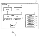
- FIG. 2 is a block diagram illustrating the configuration of the flow line analyzer 50 of the present embodiment.
- the flow line analyzer 50 is composed of an information processing device such as a personal computer or a tablet terminal.
- the flow line analyzer 50 illustrated in FIG. 2 includes a device interface 51 for connecting to an external device such as a camera 20, an operation unit 52 for receiving an operation of the user 30, a display unit 53 for displaying a screen, and a motion. It includes a control unit 54 that controls the operation of the line analyzer 50, and a storage unit 57 that stores data and programs.
- the device interface 51 is a connection circuit for connecting devices and communicating data in accordance with a standard such as USB, IEEE 802.11 or Bluetooth (registered trademark).
- the flow line analysis system 100 transfers moving image data from the camera 20 to the flow line analysis device 50 via the device interface 51.
- the device interface 51 may form an input unit for inputting a user operation from an external device.
- the operation unit 52 is composed of, for example, a keyboard, a mouse, a trackpad, a touch panel, or a combination thereof.
- the operation unit 52 acquires various information input by the user's operation.
- the operation unit 52 is an example of an input unit of the flow line analyzer 50 in the present embodiment.
- the display unit 53 is composed of, for example, a liquid crystal display or an organic EL display.
- the display unit 53 may display various types of information such as various icons for operating the operation unit 52 and information input from the operation unit 52.
- Various display devices such as a projector and a head-mounted display may be used for the display unit 53.
- the display unit 53 of the flow line analyzer 50 may be, for example, an output interface circuit for a video signal or the like conforming to an HDMI (registered trademark) standard or the like.
- the control unit 54 is composed of, for example, a CPU or MPU that realizes a predetermined function in cooperation with software.
- the control unit 54 reads out the data and the program stored in the storage unit 57, performs various arithmetic processes, and realizes various functions.
- the control unit 54 executes a program including a group of instructions for realizing various processes of the flow line analyzer 50.
- the above program is, for example, an application program, which may be provided from a communication network such as the Internet, or may be stored in a portable storage medium.
- the control unit 54 includes, for example, a flow line generation unit 55 and a flow line analysis unit 56 as functional configurations.
- the flow line generation unit 55 generates the flow line data D1 by applying the image recognition technique to the moving image data D0 stored in the storage unit 57, for example, and outputs the flow line data D1 to the storage unit 57.
- the flow line analysis unit 56 executes a process of filtering and displaying information such as a flow line based on the flow line data D1 according to a user operation in the operation unit 52. The configuration of the flow line analysis unit 56 will be described later.
- the control unit 54 may be a hardware circuit such as a dedicated electronic circuit or a reconfigurable electronic circuit designed to realize a predetermined function.
- the control unit 54 may be composed of semiconductor integrated circuits such as a CPU, MPU, GPU, GPGPU, TPU, microcomputer, DSP, FPGA and ASIC. Further, the control unit 54 may include an internal memory as a temporary storage area for holding various data and programs.
- the storage unit 57 is a recording medium for storing data and programs, and is composed of, for example, a hard disk drive (HDD) or a semiconductor storage device (SSD).
- the storage unit 57 stores various data such as moving image data D0, flow line data D1, and map data D2 indicating a map of the workplace 200.
- the map data D2 illustrated in FIG. 5 is generated by the control unit 54 from, for example, a map image input by the user 30. Details of the flow line data D1 and the map data D2 stored in the storage unit 57 will be described later.
- the storage unit 57 may include a temporary storage element composed of, for example, a RAM such as a DRAM or SRAM, or may function as a work area of the control unit 54.
- the storage unit 57 temporarily stores the retention data D3 and the area information D4, which will be described later.
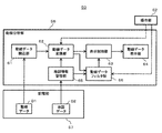
- FIG. 3 is a block diagram illustrating the functional configuration of the flow line analysis unit 56 in the present embodiment.
- the flow line analysis unit 56 displays the flow line data reading unit 61, the flow line data conversion unit 62, the display control unit 63, and the flow line data display on the display unit 53 to display the flow line and related information.
- a unit 64, a map information management unit 65 that manages the map data D2, and a flow line data filter unit 66 are provided.
- the flow line data reading unit 61 reads the flow line data D1 stored in the storage unit 57.
- the flow line data conversion unit 62 uses the flow line data D1 read from the flow line data reading unit 61 as the retention data D3 (FIG. 6) indicating the position and time at which the retention of moving objects such as workers 11 and 12 is detected. See).
- the flow line data conversion unit 62 acquires the map data D2 from the storage unit 57 via the map information management unit 65, and notifies the display control unit 63 of the information in which the map data D2 and the retention data D3 are associated with each other. ..
- the flow line data conversion unit 62 further notifies the display control unit 63 of information corresponding to the moving image of the moving image data D0 acquired from the storage unit 57 and the flow line based on the flow line data D1.
- the display control unit 63 controls the flow line data display unit 64 to display various information notified from the flow line data conversion unit 62 or the flow line data filter unit 66.
- the flow line data filter unit 66 displays information displayed on the display unit 53 by the flow line data display unit 64 according to the area information D4 input by the user operation in the operation unit 52 so as to specify the passage position of the flow line. To determine.
- the flow line analyzer 50 of the present embodiment stores the flow line data D1, the map data D2, the retention data D3, and the area information D4 in the storage unit 57 as described above.
- the flow line data D1, the map data D2, the retention data D3, and the area information D4 will be described with reference to FIGS. 4 to 7.
- FIG. 4 is a diagram for explaining the flow line data D1 in the flow line analyzer 50.
- the flow line data D1 is generated by the flow line generation unit 55 based on the moving image data D0.
- the moving objects such as the workers 11 and 12 are moved by using the image recognition technology. Detect.
- the flow line data D1 has the "time” in which the frame was recorded, the "ID” for identifying the detected moving object, and the coordinates on the map image in which the moving object is detected in each frame.
- the indicated “X” and "Y” are associated and stored.
- the coordinates X and Y are the coordinates in the width direction and the height direction of the map image, respectively.
- the flow line analysis unit 56 displays the flow line by combining the coordinates X and Y of the data having the same ID in the flow line data D1 in chronological order according to the time associated with the coordinates. Further, the flow line analysis unit 56 displays a moving image of the time section corresponding to the flow line from the moving image data D0 based on the time interval combined as the flow line in the flow line data D1. As shown in FIG. 4, the flow line data D1 may include data having a plurality of different IDs at the same time due to the simultaneous detection of a plurality of moving objects.
- FIG. 5 is a diagram for explaining the map data D2.
- the map data D2 records the "map image", the "width”, the “height”, and the “scale” in association with each other.
- the "map image” indicates image data of a map such as the layout of various facilities in the workplace 200.
- "Width” and “height” indicate the width and height of the map image.
- “Scale” indicates the scale of the workplace 200 and the map.
- the unit of width and height of the image is, for example, centimeters.
- the map image is acquired in advance from the outside of the flow line analyzer 50 by the device interface 51, for example, in response to a user operation in the operation unit 52.
- FIG. 6 is a diagram for explaining the retention data D3.
- the retention data D3 is stored as a data record in association with "start time”, “end time”, “ID”, “X”, and “Y”.
- the retention data D3 is obtained by converting the flow line data D1 by the flow line data conversion unit 62 of the flow line analysis unit 56 shown in FIG.
- the flow line data conversion unit 62 determines that the moving body identified by the ID has accumulated, and determines that the moving body is retained.
- the retention data D3 is generated.
- the predetermined range is a narrow range that can be regarded as one point, and for example, the coordinates of the center of the range are used as the coordinates in the retention data D3.
- the predetermined time is such a long time that the moving body can be regarded as having stopped within a predetermined range.
- the "start time” and the “end time” indicate the retention start time and end time based on the time recorded in the flow line data D1.
- “ID” indicates an ID detected in the flow line data D1 from the start time to the end time.
- “X” and “Y” indicate the coordinates X and Y of one point in the range of coordinates in the vicinity determined to be stagnant, and indicate, for example, the intersections of regions in which the map image is divided in a grid pattern at predetermined intervals.
- the range indicating the predetermined time, the predetermined interval, and the vicinity of the predetermined coordinates may be set by the user 30. Further, the retention data D3 may include data having a plurality of different IDs at the same time by detecting the retention of a plurality of moving objects at the same time.
- FIG. 7 is a diagram for explaining the area information D4 in the flow line analyzer 50.
- the area information D4 is input to the flow line data filter unit 66 by the operation unit 52, for example, by a user operation of designating a rectangular area on the map image displayed on the display unit 53.
- the area information D4 stores “X”, “Y”, “width”, and “height” in association with each other.
- “X” and “Y” indicate one vertex of a rectangular area designated by the user 30 on the map image.
- "Width” and “height” indicate the width and height of the rectangular area, for example, in units of centimeters.
- the flow line analyzer 50 acquires the moving image data D0 obtained by the camera 20 of the moving image of the work place 200 in which the workers 11 and 12 and the like move, and stores the moving image data D0 in the storage unit 57. accumulate.
- the flow line analyzer 50 generates the flow line data D1 from the moving image data D0, for example, in the flow line generation unit 55.
- the flow line analyzer 50 of the present embodiment displays information such as a flow line based on the flow line data D1 so that the user 30 can analyze it according to the operation of the user 30. Display examples of the flow line analyzer 50 are shown in FIGS. 8 to 9.
- FIG. 8A illustrates a state before the display unit 53 of the flow line analyzer 50 displays the flow line.
- the retention area 80 is displayed on the map image M1 of the map data D2.
- the retention area 80 indicates a position where the flow line stays based on the retention data D3 obtained from the flow line data D1.
- the display unit 53 of the flow line analyzer 50 displays a plurality of retention areas 80.
- the retention area 80 is an example of a retention location in the present embodiment.
- the retention area 80 has a size corresponding to the length of the period in which the moving body such as the workers 11 and 12 stays.
- the retention area 80 has a larger radius under the control of the display control unit 63, centering on the coordinates X and Y in the retention data D3, as the retention period is longer, that is, the difference between the start time and the end time in the retention data D3 is larger. Is displayed as a circle with.
- the flow line analyzer 50 accurately visualizes the tendency of the workers 11 and 12 and the like in the workplace 200 to be accurately visualized by the retention area 80 obtained by accumulating a large number of flow lines by, for example, the moving image data D0 over a long period of time. Can be done.
- FIG. 8 (B) illustrates a state in which the flow line 90 is displayed from FIG. 8 (A).
- the flow line analyzer 50 receives a user operation of selecting one retention area from a plurality of retention areas 80 at the time of display as illustrated in FIG. 8A in the operation unit 52.
- the specific retention area selected in such a user operation is hereinafter referred to as "retention area As".
- the user 30 can select the retention area As for which the flow line 90 is to be analyzed in consideration of, for example, the work performed by the workers 11 and 12 in the work place 200.
- FIG. 9A shows a display example of the display unit 53 displaying the moving image list T1 in the state of FIG. 8B.
- the display unit 53 displays a plurality of flow lines 90 staying in the selected staying area As from the state of FIG. 8A, and also displays the corresponding moving image list T1.
- the moving image list T1 for example, for each ID of the displayed flow line 90, the moving image link for displaying the moving image of the moving image data D0 corresponding to each moving line 90 and the staying start time in the staying data D3 are displayed in association with each other. ..
- the flow line analyzer 50 makes it possible to watch the video corresponding to each displayed flow line 90. By viewing the moving image, the user 30 can analyze, for example, the factor that formed the flow line 90 based on the moving image.
- the moving images indicated by the moving image list T1 and the moving image link of the moving image list T1 are examples of related information in the present embodiment, respectively.
- the moving image list T1 includes a large number of moving image links corresponding to each flow line 90. It will be. In this way, if the video candidates are excessively displayed, it takes an excessive amount of time for the user 30 to watch all the videos. Therefore, even if the user 30 selects the retention area As to be analyzed, it may be difficult to find a desired moving image, and it may be difficult to analyze the flow line. Therefore, the flow line analyzer 50 of the present embodiment separately accepts a user operation for designating a passing area through which the flow line passes in addition to selecting the retention area As, and narrows down the candidates for the moving image.
- FIG. 9B shows a display example when the passage area Ap is specified by the user operation from the state of FIG. 9A.
- the number of displayed flow lines 90 is reduced from the large number of flow lines 90 displayed in FIG. 9A to two passing through the passing area Ap.
- the moving image list T2 displays only the moving image links corresponding to the two flow lines 90 that stay in the staying area As and pass through the passing area Ap.
- the flow line analyzer 50 of the present embodiment that performs such a display, the user 30 only needs to confirm the video indicated by a small number of video links for the analysis of the flow line, and analyzes the flow line and its related information. It becomes easier to do. Further, the flow line analyzer 50 only needs to generate a small number of moving image links, and can reduce the processing load in displaying related information.
- FIG. 10 is a flowchart for explaining the operation of the flow line analysis unit 56.
- Each process shown in the flowchart of FIG. 10 is executed, for example, by the control unit 54 functioning as the flow line analysis unit 56 after executing the operation as the flow line generation unit 55.
- the flowchart of FIG. 10 is started when, for example, the operation unit 52 inputs a predetermined operation for starting the analysis of the flow line or the like by the user 30.
- the control unit 54 as the flow line analysis unit 56 acquires various data from the storage unit 57 (S1). For example, as shown in FIG. 3, the flow line data reading unit 61 of the flow line analysis unit 56 reads the flow line data D1 (see FIG. 4). Further, the map information management unit 65 acquires the map data D2 (see FIG. 5). The flow line data conversion unit 62 generates stay data D3 (see FIG. 6) based on the flow line data D1 from the flow line data reading unit 61, and displays the display control unit 63 together with the map data D2 from the map information management unit 65. Output to.
- the flow line data reading unit 61 of the flow line analysis unit 56 reads the flow line data D1 (see FIG. 4).
- the map information management unit 65 acquires the map data D2 (see FIG. 5).
- the flow line data conversion unit 62 generates stay data D3 (see FIG. 6) based on the flow line data D1 from the flow line data reading unit 61, and displays the display control unit 63 together with the map
- control unit 54 functions as a display control unit 63 and a flow line data display unit 64, and as shown in FIG. 8A, for example, the retention area 80 based on the retention data D3 is converted into a map of the map data D2. It is superimposed on the image M1 and displayed on the display unit 53 (S2). Specifically, the flow line data display unit 64 displays the retention area 80 by associating the coordinates X and Y in the map data D2 with the coordinates X and Y in the retention data D3.
- control unit 54 determines whether or not a user operation for selecting the retention area As has been input in the operation unit 52 (S3).
- the operation of selecting the retention area As is, for example, an operation of clicking the retention area As with a mouse or the like or touching with a touch pad or the like.
- control unit 54 determines that the selection operation of the retention area As has not been input (NO in S3), the control unit 54 repeats the determination in step S3.
- the control unit 54 displays the flow line 90 retained in the retention area As on the map image M1 as shown in FIG. 8B, for example.
- the display unit 53 is controlled so as to (S4).
- the processing of this step is performed with reference to, for example, the retention data D3 generated by the control unit 54 as the flow line data conversion unit 62.
- step S4 the control unit 54 first collects data records corresponding to the coordinates X and Y of the selected retention area As in the retention data D3 illustrated in FIG.
- the control unit 54 detects the time in the flow line data D1 illustrated in FIG. 4, the time in the data record in which the coordinates X and Y are collected from the retention data D3, the ID of the flow line including the coordinates X and Y, and the like.
- the control unit 54 generates a moving image link for displaying the moving image corresponding to each flow line extracted by the flow line data conversion unit 62, and displays the moving image list T1 as shown in FIG. 9A, for example. It may be displayed.
- control unit 54 functions as, for example, a flow line data filter unit 66, and determines whether or not a user operation for designating the passage area Ap has been input in the operation unit 52 (S5).
- the operation for designating the passing area Ap is an operation in which a rectangular area is designated as the passing area Ap on the map image M1 by, for example, a mouse or a touch pad.
- the passage area Ap is an example of a designated location in the present embodiment.
- control unit 54 determines that the designated operation of the passing area Ap has not been input (NO in S5), the control unit 54 repeats the determination in step S5.
- the control unit 54 When the operation for designating the passing area Ap is input (YES in S5), the control unit 54 extracts the flow line 90 passing through the passing area Ap from the flow lines 90 staying in the staying area As and displays it on the display unit 53. Display (S6).
- the processing of this step is performed, for example, by the control unit 54 acquiring the area information D4 (see FIG. 7) indicating the passing area Ap from the operation unit 52 and functioning as the flow line data filter unit 66.
- step S6 the flow line data filter unit 66 acquires information indicating the flow line 90 extracted from the flow line data conversion unit 62 using the retention area As.
- the flow line data filter unit 66 stays in the staying area As by detecting the flow line 90 including the coordinates X and Y within the range of the passing area Ap indicated by the area information D4 from the flow line 90 of the acquired information. Then, the flow line 90 passing through the passing area Ap is extracted.
- control unit 54 generates a moving image link indicating a moving image corresponding to each flow line determined as the flow line data filter unit 66, and displays the moving image list T2 on the display unit 53 (S7).
- FIG. 9B is displayed by the processing of steps S6 to S7.
- control unit 54 determines whether or not a user operation for selecting a video to be displayed from the video link in the video list T2 has been input in the operation unit 52 (S8).
- the moving image selection operation is, for example, a clicking operation of a moving image link with a mouse or the like, or a touch operation with a touch pad or the like.
- control unit 54 causes the display unit 53 to display the selected video so as to play it (S9).
- control unit 54 determines that the moving image selection operation has not been input (NO in S8), for example, the determination in step S8 is repeated.
- the control unit 54 ends the process according to this flowchart after the moving image is reproduced and displayed (S9).
- steps S8 to S9 a plurality of moving images may be reproduced and displayed.
- the retention area 80 is displayed based on the flow line data D1 (S2), and the flow line 90 retained in the retention area As selected by the user 30 is displayed (S4). ..
- the control unit 54 further extracts the flow line 90 by the passing area Ap designated by the user operation in addition to the retention area As, and the extracted flow line 90. , And the corresponding video list T2 are displayed (S6, S7).
- the flow line analysis unit 56 narrows down the flow lines 90 and the moving image to be displayed according to the passage area Ap specified by the user, so that when the user 30 analyzes the related information of the flow lines 90, the flow lines 90 It is possible to make it easier to check the video corresponding to.
- control unit 54 extracts the flow line 90 passing through the passage area Ap designated by the user 30 and displays it together with the corresponding moving image list T2 (S6, S7).
- the user 30 can designate a place unrelated to the work as expected from the selected stay area As as the passing area Ap in the work place 200.
- step S8 of the present embodiment when the control unit 54 determines that the moving image is not selected (NO in S8), the control unit 54 repeatedly executes the determination in step S8, but the present invention is not limited to this.
- the control unit 54 may re-execute the processes after step S5.
- the number of staying areas As selected in step S3 is not limited to one, and may be plural. In this case, the control unit 54 may display the flow lines 90 staying in all of the selected staying areas As on the display unit 53, or display the flow lines 90 staying in any of the selected staying areas As. May be good.
- the flow line analysis device 50 of the flow line analysis system 100 displays related information related to the flow lines of the moving objects such as the workers 11 and 12.
- the flow line analyzer 50 includes a display unit 53, a storage unit 57, an operation unit 52 (input unit), and a control unit 54.
- the display unit 53 displays the flow line 90 and the moving images and the moving image lists T1 to T2 corresponding to each flow line 90 as an example of the related information (S4, S6, S7, S9).
- the storage unit 57 stores the flow line data D1 indicating the plurality of flow lines 90 and related information.
- the operation unit 52 receives the input by the user's operation (S3, S8).
- the control unit 54 controls the display unit 53 based on the information stored in the storage unit 57 and the user operation input from the operation unit 52.
- the control unit 54 displays the retention area 80 on the display unit 53 as an example of the retention location where the flow line has accumulated based on the flow line data D1, and selects at least one retention area from the operation unit 52. (S2, S3).
- the control unit 54 further inputs a user operation for designating the passage area Ap as an example of a designated location different from the selected residence area As from the operation unit 52, and inputs the user operation to the selected residence area As and the passage area Ap. Based on this, the related information displayed on the display unit 53 is extracted (S6, S7).
- the flow line analyzer 50 limits the related information to be displayed on the display unit 53 by designating the passing area Ap in addition to selecting the staying area As.
- the flow line analysis device 50 can make it easier for the user 30 to analyze the related information of the flow line by limiting the related information to be displayed according to the designation of the user 30 of the flow line analysis system 100. .. Further, the flow line analyzer 50 can reduce the processing load for display by limiting the related information to be displayed.
- the control unit 54 displays the video list T2 as an example of the related information of the flow lines that stay in the selected retention area As and pass through the designated passage area Ap among the plurality of flow lines 90.
- the related information displayed on the display unit 53 is limited (S7).
- the flow line analyzer 50 filters and displays the related information confirmed by the user 30 in two stages according to the retention area As and the passing area Ap, so that the user 30 analyzes the related information of the flow line. It can be made easier.
- the control unit 54 displays the flow line accumulated in the selected retention location As among the plurality of flow lines 90 on the display unit 53. (S4).
- the control unit 54 limits the flow line displayed on the display unit 53 from the flow line staying in the staying area As based on the designated passing area Ap (). S6).
- the flow line analyzer 50 in addition to the selection of the retention area As, when the passage area Ap is specified by the user 30, only the flow lines that stay in the retention area As and pass through the passage area Ap are displayed. The flow. For example, when a place unrelated to the work in the stay area As of the work place 200 is designated as the passing area Ap, the flow line including the behavior unrelated to the above work and its related information can be extracted. As a result, the flow line analyzer 50 can easily analyze the related information of the flow line that the user 30 needs to consider.
- the storage unit 57 further stores a map in which moving objects such as workers 11 and 12 are located, that is, map data D2 indicating a map image M1.
- the control unit 54 superimposes the retention area 80 on the map and displays it on the display unit 53.
- the user 30 can confirm the flow line on the map image M1 of the map data D2, and it is easy to analyze the flow line and the like.
- the related information includes at least one of a moving object and, as an example of a list including video candidates, video lists T1 and T2.
- the user 30 can specifically confirm the movement of the moving body by the moving image.
- the flow line analysis method in this embodiment displays related information related to the flow line by the moving body.
- the control unit 54 displays the retention area 80 on the display unit 53 as an example of the retention location where the flow line stays based on the flow line data D1 stored in the storage unit 57, and causes the operation unit 52 (input).
- the passage area Ap is specified as an example of a location different from the steps S2 and S3 for acquiring the input result by the user operation for selecting at least one retention area from the operation unit) and the retention location As selected from the operation unit 52. It includes steps S5 to S7 of acquiring the input by the user operation and limiting the related information displayed on the display unit 53 based on the stayed portion As and the designated portion Ap.
- a program for causing the control unit of the computer to execute the above-mentioned flow line analysis method is provided.
- the user 30 can easily analyze the related information of the flow line.
- FIG. 11 shows a display example of the flow line analyzer 50 according to the second embodiment.
- a predetermined division area 85 is set in the flow line analyzer 50.
- the division area 85 is set according to the map data D2 so as to divide the entire map image M1 in a grid pattern, for example.
- the flow line analyzer 50 in the present embodiment counts and counts the number of times the flow line staying in the staying area As passes through the divided area 85 for each divided area 85 in the state where the staying area As is selected. The number of passes is displayed in each divided area 85.
- the display example of FIG. 11 shows a state in which a user operation for selecting a divided area in which the number of passages is counted once is input.
- the specific divided area selected in such a user operation is hereinafter referred to as "divided area Ac".
- the flow line analyzer 50 extracts and displays the flow line 91 passing through the selected divided area Ac from the flow line staying in the staying area As.
- the flow line analyzer 50 displays a moving image list T3 including a moving image link of a moving image corresponding to the moving line 91 together with one moving line 91 that stays in the staying area As and passes through the divided area Ac.
- FIG. 12 is a flowchart for explaining the operation of the flow line analysis unit 56 according to the second embodiment.
- the control unit 54 responds to the number of times the flow line has passed, as shown in FIG. Processes for narrowing down the flow lines to be displayed by selecting the divided area Ac are executed (S11 to S13).
- the control unit 54 of the flow line analyzer 50 holds, for example, information in which a plurality of divided areas 85 as shown in FIG. 12 are associated with the map image M1 of the map data D2 in an internal memory or the like.
- the control unit 54 of the present embodiment as the flow line analysis unit 56, counts the number of times the flow line staying in the retention area As selected in step S3 passes through each division area 85, and sets the number of passages for each division area 85. Is superimposed on the map image M1 and displayed on the display unit 53 (S11). At this time, the control unit 54 may display the flow line staying in the staying area As as in S4 of FIG.
- the control unit 54 determines whether or not a user operation for selecting one division area Ac has been input in the operation unit 52 as the flow line analysis unit 56 (S12).
- control unit 54 determines that the user operation for selecting the division area Ac has not been input (NO in S12)
- the control unit 54 repeats the determination in step S12, for example.
- the control unit 54 selects the selected division area Ac from the flow lines retained in the retention area As, similarly to the flow line analysis unit 56 of the first embodiment.
- the flow line 91 passing through is extracted.
- the flow line analysis unit 56 causes the display unit 53 to display the extracted flow line 91 (S13).
- the user 30 of the flow line analysis system 100 confirms, for example, the divided area 85 having a small number of passages and selects it as the divided area Ac to investigate movements that do not normally occur in the work in the workplace 200. As you can, you can analyze the video about the flow line.
- the selected division area Ac is an example of a designated location in the present embodiment.
- the map image M1 of the map data D2 is divided into a plurality of divided areas 85.
- the control unit 54 causes the display unit 53 to display the number of times the flow line staying in the staying area As as an example of the selected staying place passes in each of the divided areas 85 (S11).
- the control unit 54 accepts a user operation in the operation unit 52 (input unit) to specify any of the plurality of divided areas 85 as an example of the designated location (S12, S13).
- the user 30 of the system 100 can analyze the moving image of the flow line including the peculiar behavior in the workplace 200 by selecting, for example, a place where the flow line rarely passes.
- Embodiments 1 and 2 have been described as examples of the techniques disclosed in this application. However, the technique in the present disclosure is not limited to this, and can be applied to embodiments in which changes, replacements, additions, omissions, etc. are made as appropriate. It is also possible to combine the components described in each of the above embodiments into a new embodiment.
- the camera 20 of the flow line analysis system 100 has described the movements of the workers 11 and 12 as an example of a moving body.
- the moving body is not particularly limited to a person, and may be a vehicle such as a truck, a forklift, or a train.
- the camera 20 of the flow line analysis system 100 was installed in the work place 200.
- the camera 20 of the present embodiment is not particularly limited to the work place 200, and may be installed in a moving body such as a vehicle.
- the flow line data D1 may be generated from the moving image taken by the moving camera 20 by using, for example, a technique of self-position estimation.
- the flow line analysis system 100 generated the flow line data D1 based on the moving line data D0 by the camera 20.
- the flow line analysis system 100 of the present embodiment is not limited to the moving line data D0 by the camera 20, for example, the workplace 200 and the moving body have a device capable of transmitting and receiving a beacon signal, and the flow line data D1 is obtained based on the beacon signal. It may be generated. Further, the flow line data D1 may be generated by tracking the movement of a vehicle or the like using a technique such as GPS.
- the flow line analyzer 50 of the flow line analysis system 100 displays the moving line list T1 when displaying the flow lines accumulated in the selected retention area As (S4 in FIG. 10) (FIG. 10). 9).
- the flow line analyzer 50 of the present embodiment does not have to display the moving image list T1 in particular. Further, the flow line analyzer 50 of the present embodiment may display the moving image list T1 only when, for example, the number of flow lines to be displayed is equal to or less than a predetermined threshold value, and may not display the moving line list T1 in other cases.
- the flow line analyzer 50 inputs the passing area Ap, which is an example of the designated location, as a rectangular area, and acquires the area information D4 (S6 in FIG. 10).
- the passage area Ap is not particularly limited to a rectangular region, and may be, for example, a region surrounded by a curve.
- the designated portion of the present embodiment is not limited to the input as an area, and may be, for example, a line.
- the flow line analyzer 50 inputs the passing area Ap, which is an example of the designated location, and displays the flow line 90 passing through the passing area Ap and the corresponding moving image list T2 (S6 to S7 in FIG. 10).
- a plurality of passage areas Ap may be specified. An example of such a modification will be described with reference to FIG.
- FIG. 13 is a flowchart for explaining the operation of the flow line analysis unit 56 in the flow line analysis device 50 according to the modified example of the first embodiment.
- the control unit 54 which functions as the flow line analysis unit 56, for example, in addition to the processes of steps S1 to S9 in FIG. 10, after narrowing down the flow lines and the like (S6 to S7) by designating the passage area Ap (S5), It is determined whether or not the operation of adding or deleting the passage area Ap has been input by the user 30 (S21). The operation is input as, for example, a designated operation of the passing area Ap to be added or deleted.
- the control unit 54 updates the area information D4 (see FIG. 7) and executes the processes of steps S6 to S7 again. For example, when a plurality of passing areas Ap are added, the control unit 54 displays the flow lines 90 and the like passing through all the passing areas Ap (S6 to S7). If the passage area Ap has not been added or deleted (NO in S21), the control unit 54 proceeds to the process of step S8 and subsequent steps. In this way, by narrowing down the flow lines 90 and the like to be displayed according to the passage area Ap added or deleted by the user operation, the user 30 can easily analyze the related information of the flow lines 90.
- the flow line analyzer 50 inputs a user operation for selecting a moving image link displayed in the moving image lists T1 to T3 (S8 in FIGS. 10 and 12) to display the moving image (S8 in FIGS. 10 and 12). S9 in FIGS. 10 and 12).
- the flow line analyzer 50 in the present embodiment may display a moving image by inputting a user operation for directly selecting a flow line without executing the process of step S8 in particular.
- the present disclosure is applicable to a flow line analyzer and a flow line analysis method that display related information related to the flow line by a moving body.
Landscapes
- Engineering & Computer Science (AREA)
- Business, Economics & Management (AREA)
- Theoretical Computer Science (AREA)
- Physics & Mathematics (AREA)
- General Physics & Mathematics (AREA)
- Strategic Management (AREA)
- Economics (AREA)
- Entrepreneurship & Innovation (AREA)
- Human Resources & Organizations (AREA)
- Development Economics (AREA)
- Multimedia (AREA)
- Marketing (AREA)
- General Business, Economics & Management (AREA)
- Finance (AREA)
- Accounting & Taxation (AREA)
- General Engineering & Computer Science (AREA)
- Game Theory and Decision Science (AREA)
- Computer Vision & Pattern Recognition (AREA)
- Quality & Reliability (AREA)
- Tourism & Hospitality (AREA)
- Operations Research (AREA)
- Human Computer Interaction (AREA)
- Educational Administration (AREA)
- Mathematical Physics (AREA)
- Computational Linguistics (AREA)
- Data Mining & Analysis (AREA)
- Databases & Information Systems (AREA)
- User Interface Of Digital Computer (AREA)
- Management, Administration, Business Operations System, And Electronic Commerce (AREA)
- Information Retrieval, Db Structures And Fs Structures Therefor (AREA)
Priority Applications (3)
| Application Number | Priority Date | Filing Date | Title |
|---|---|---|---|
| EP20908264.3A EP4083893A4 (en) | 2019-12-26 | 2020-11-20 | Flow line analysis device and flow line analysis method |
| JP2021567077A JP7561341B2 (ja) | 2019-12-26 | 2020-11-20 | 動線分析装置及び動線分析方法 |
| US17/842,954 US12243245B2 (en) | 2019-12-26 | 2022-06-17 | Trajectory analysis device and trajectory analysis method |
Applications Claiming Priority (2)
| Application Number | Priority Date | Filing Date | Title |
|---|---|---|---|
| JP2019-236729 | 2019-12-26 | ||
| JP2019236729 | 2019-12-26 |
Related Child Applications (1)
| Application Number | Title | Priority Date | Filing Date |
|---|---|---|---|
| US17/842,954 Continuation US12243245B2 (en) | 2019-12-26 | 2022-06-17 | Trajectory analysis device and trajectory analysis method |
Publications (1)
| Publication Number | Publication Date |
|---|---|
| WO2021131448A1 true WO2021131448A1 (ja) | 2021-07-01 |
Family
ID=76575210
Family Applications (1)
| Application Number | Title | Priority Date | Filing Date |
|---|---|---|---|
| PCT/JP2020/043355 Ceased WO2021131448A1 (ja) | 2019-12-26 | 2020-11-20 | 動線分析装置及び動線分析方法 |
Country Status (4)
| Country | Link |
|---|---|
| US (1) | US12243245B2 (https=) |
| EP (1) | EP4083893A4 (https=) |
| JP (1) | JP7561341B2 (https=) |
| WO (1) | WO2021131448A1 (https=) |
Cited By (2)
| Publication number | Priority date | Publication date | Assignee | Title |
|---|---|---|---|---|
| WO2023037616A1 (ja) * | 2021-09-09 | 2023-03-16 | パナソニックIpマネジメント株式会社 | 経路生成表示装置および経路生成表示方法 |
| EP4462770A4 (en) * | 2022-01-07 | 2025-03-12 | Panasonic Intellectual Property Management Co., Ltd. | DATA ANALYSIS DEVICE AND METHOD |
Citations (4)
| Publication number | Priority date | Publication date | Assignee | Title |
|---|---|---|---|---|
| JP2006350751A (ja) | 2005-06-17 | 2006-12-28 | Hitachi Ltd | 店舗内の販売分析装置及びその方法 |
| JP2010123069A (ja) * | 2008-11-21 | 2010-06-03 | Panasonic Corp | センシングデータ検索装置及び検索画像作成方法 |
| JP2015087841A (ja) * | 2013-10-29 | 2015-05-07 | パナソニック株式会社 | 滞留状況分析装置、滞留状況分析システムおよび滞留状況分析方法 |
| WO2018079456A1 (ja) * | 2016-10-31 | 2018-05-03 | 日本電気株式会社 | 動線出力装置、動線出力方法及び記録媒体 |
Family Cites Families (7)
| Publication number | Priority date | Publication date | Assignee | Title |
|---|---|---|---|---|
| JP4510112B2 (ja) * | 2008-04-11 | 2010-07-21 | 東芝テック株式会社 | 動線解析装置 |
| JP2011248836A (ja) | 2010-05-31 | 2011-12-08 | Nomura Research Institute Ltd | 滞留検出システム及びプログラム |
| WO2015129210A1 (ja) * | 2014-02-25 | 2015-09-03 | 日本電気株式会社 | 情報処理装置、データ分析方法、及び、記録媒体 |
| KR102015954B1 (ko) * | 2014-03-21 | 2019-08-29 | 한화테크윈 주식회사 | 영상 처리 시스템 및 영상 처리 방법 |
| JP6464024B2 (ja) | 2015-04-27 | 2019-02-06 | 株式会社日立ソリューションズ | 行動分析システム及び行動分析方法 |
| JP2017123026A (ja) | 2016-01-06 | 2017-07-13 | パナソニックIpマネジメント株式会社 | 動線分析システム及び動線分析方法 |
| CN110476421A (zh) * | 2017-03-31 | 2019-11-19 | 日本电气株式会社 | 视频图像处理设备、视频图像分析系统、方法和程序 |
-
2020
- 2020-11-20 EP EP20908264.3A patent/EP4083893A4/en active Pending
- 2020-11-20 JP JP2021567077A patent/JP7561341B2/ja active Active
- 2020-11-20 WO PCT/JP2020/043355 patent/WO2021131448A1/ja not_active Ceased
-
2022
- 2022-06-17 US US17/842,954 patent/US12243245B2/en active Active
Patent Citations (4)
| Publication number | Priority date | Publication date | Assignee | Title |
|---|---|---|---|---|
| JP2006350751A (ja) | 2005-06-17 | 2006-12-28 | Hitachi Ltd | 店舗内の販売分析装置及びその方法 |
| JP2010123069A (ja) * | 2008-11-21 | 2010-06-03 | Panasonic Corp | センシングデータ検索装置及び検索画像作成方法 |
| JP2015087841A (ja) * | 2013-10-29 | 2015-05-07 | パナソニック株式会社 | 滞留状況分析装置、滞留状況分析システムおよび滞留状況分析方法 |
| WO2018079456A1 (ja) * | 2016-10-31 | 2018-05-03 | 日本電気株式会社 | 動線出力装置、動線出力方法及び記録媒体 |
Non-Patent Citations (1)
| Title |
|---|
| See also references of EP4083893A4 |
Cited By (2)
| Publication number | Priority date | Publication date | Assignee | Title |
|---|---|---|---|---|
| WO2023037616A1 (ja) * | 2021-09-09 | 2023-03-16 | パナソニックIpマネジメント株式会社 | 経路生成表示装置および経路生成表示方法 |
| EP4462770A4 (en) * | 2022-01-07 | 2025-03-12 | Panasonic Intellectual Property Management Co., Ltd. | DATA ANALYSIS DEVICE AND METHOD |
Also Published As
| Publication number | Publication date |
|---|---|
| JP7561341B2 (ja) | 2024-10-04 |
| US12243245B2 (en) | 2025-03-04 |
| EP4083893A4 (en) | 2023-02-08 |
| JPWO2021131448A1 (https=) | 2021-07-01 |
| EP4083893A1 (en) | 2022-11-02 |
| US20220319021A1 (en) | 2022-10-06 |
Similar Documents
| Publication | Publication Date | Title |
|---|---|---|
| US11105749B2 (en) | Information processing apparatus, information processing method and program | |
| JP6319421B2 (ja) | 情報処理装置、データ分析方法、及び、プログラム | |
| JP6631638B2 (ja) | 表示方法、表示プログラム及び表示制御装置 | |
| JP6519656B2 (ja) | 製造工程管理システム、製造工程管理方法および製造工程管理プログラム | |
| JP2019520649A (ja) | プロセス視覚化プラットフォーム | |
| US20130212039A1 (en) | Review timeline for ownership lifecycle experience | |
| CN111596619B (zh) | 计算机系统及设施的监视方法 | |
| WO2012125157A1 (en) | Usability testing | |
| US12243245B2 (en) | Trajectory analysis device and trajectory analysis method | |
| WO2019087275A1 (ja) | 作業分析装置、及び作業分析方法 | |
| CN112667212A (zh) | 埋点数据可视化方法、装置、终端和存储介质 | |
| JP2014067225A (ja) | 行動傾向提示装置、行動傾向提示方法、行動傾向提示プログラム、及び、行動傾向提示システム | |
| JP2016062230A (ja) | 情報処理装置、情報処理方法およびプログラム | |
| CN114003473A (zh) | 一种页面操作行为的回溯方法、装置及电子设备 | |
| JP7653438B2 (ja) | プロジェクト診断dbシステム | |
| US20240046285A1 (en) | Information analysis device and information analysis method | |
| US20150095825A1 (en) | Person image display control apparatus, method of controlling same, and recording medium storing control program therefor | |
| JP6453584B2 (ja) | 保全支援装置、保全支援方法、及びプログラム | |
| US10372297B2 (en) | Image control method and device | |
| US9589020B2 (en) | Matching method and computer-readable recording medium | |
| US20230267727A1 (en) | Image analysis apparatus, image analysis method, and storage medium | |
| JP7243133B2 (ja) | 稼働状態判定装置、稼働状態判定方法、およびプログラム | |
| JP7188478B2 (ja) | 検索装置、検索方法、およびプログラム | |
| JP2025166690A (ja) | 作業分析装置 | |
| WO2025109937A1 (ja) | 監視システム及び監視方法 |
Legal Events
| Date | Code | Title | Description |
|---|---|---|---|
| 121 | Ep: the epo has been informed by wipo that ep was designated in this application |
Ref document number: 20908264 Country of ref document: EP Kind code of ref document: A1 |
|
| DPE2 | Request for preliminary examination filed before expiration of 19th month from priority date (pct application filed from 20040101) | ||
| ENP | Entry into the national phase |
Ref document number: 2021567077 Country of ref document: JP Kind code of ref document: A |
|
| NENP | Non-entry into the national phase |
Ref country code: DE |
|
| ENP | Entry into the national phase |
Ref document number: 2020908264 Country of ref document: EP Effective date: 20220726 |