WO2021124583A1 - フローリアクター - Google Patents
フローリアクター Download PDFInfo
- Publication number
- WO2021124583A1 WO2021124583A1 PCT/JP2019/050217 JP2019050217W WO2021124583A1 WO 2021124583 A1 WO2021124583 A1 WO 2021124583A1 JP 2019050217 W JP2019050217 W JP 2019050217W WO 2021124583 A1 WO2021124583 A1 WO 2021124583A1
- Authority
- WO
- WIPO (PCT)
- Prior art keywords
- flow path
- reaction
- heat transfer
- outer cylinder
- cylinder
- Prior art date
Links
- 238000006243 chemical reaction Methods 0.000 claims abstract description 165
- 239000012530 fluid Substances 0.000 claims abstract description 101
- 238000000576 coating method Methods 0.000 claims abstract description 13
- 239000011248 coating agent Substances 0.000 claims abstract description 11
- 238000012546 transfer Methods 0.000 claims description 103
- 230000004323 axial length Effects 0.000 claims description 13
- 239000000470 constituent Substances 0.000 claims description 13
- 239000000463 material Substances 0.000 claims description 13
- 238000005260 corrosion Methods 0.000 claims description 12
- 230000007797 corrosion Effects 0.000 claims description 12
- 238000005524 ceramic coating Methods 0.000 claims description 4
- 239000011521 glass Substances 0.000 claims description 4
- 238000004140 cleaning Methods 0.000 abstract description 8
- 230000005540 biological transmission Effects 0.000 abstract 5
- 238000005192 partition Methods 0.000 abstract 1
- 230000002093 peripheral effect Effects 0.000 description 52
- 239000007789 gas Substances 0.000 description 9
- 238000003466 welding Methods 0.000 description 9
- 239000007788 liquid Substances 0.000 description 8
- XLYOFNOQVPJJNP-UHFFFAOYSA-N water Substances O XLYOFNOQVPJJNP-UHFFFAOYSA-N 0.000 description 7
- 239000002002 slurry Substances 0.000 description 6
- 238000010438 heat treatment Methods 0.000 description 5
- 238000001816 cooling Methods 0.000 description 4
- 239000011346 highly viscous material Substances 0.000 description 4
- 239000000126 substance Substances 0.000 description 4
- 238000005452 bending Methods 0.000 description 3
- 239000003054 catalyst Substances 0.000 description 3
- 239000007809 chemical reaction catalyst Substances 0.000 description 3
- 239000002184 metal Substances 0.000 description 3
- 238000012986 modification Methods 0.000 description 3
- 230000004048 modification Effects 0.000 description 3
- 238000012545 processing Methods 0.000 description 3
- IJGRMHOSHXDMSA-UHFFFAOYSA-N Atomic nitrogen Chemical compound N#N IJGRMHOSHXDMSA-UHFFFAOYSA-N 0.000 description 2
- 229910001873 dinitrogen Inorganic materials 0.000 description 2
- 230000003670 easy-to-clean Effects 0.000 description 2
- 230000000694 effects Effects 0.000 description 2
- 239000013529 heat transfer fluid Substances 0.000 description 2
- 238000009776 industrial production Methods 0.000 description 2
- 230000014759 maintenance of location Effects 0.000 description 2
- 238000004519 manufacturing process Methods 0.000 description 2
- 230000001737 promoting effect Effects 0.000 description 2
- 230000035484 reaction time Effects 0.000 description 2
- 239000003507 refrigerant Substances 0.000 description 2
- 238000004904 shortening Methods 0.000 description 2
- 238000005520 cutting process Methods 0.000 description 1
- 238000013461 design Methods 0.000 description 1
- 238000001704 evaporation Methods 0.000 description 1
- 230000008020 evaporation Effects 0.000 description 1
- 239000010419 fine particle Substances 0.000 description 1
- 238000009434 installation Methods 0.000 description 1
- 238000005304 joining Methods 0.000 description 1
- 239000000203 mixture Substances 0.000 description 1
- 239000011295 pitch Substances 0.000 description 1
- 238000013341 scale-up Methods 0.000 description 1
- 238000000926 separation method Methods 0.000 description 1
- 230000003068 static effect Effects 0.000 description 1
Images


Classifications
-
- B—PERFORMING OPERATIONS; TRANSPORTING
- B01—PHYSICAL OR CHEMICAL PROCESSES OR APPARATUS IN GENERAL
- B01J—CHEMICAL OR PHYSICAL PROCESSES, e.g. CATALYSIS OR COLLOID CHEMISTRY; THEIR RELEVANT APPARATUS
- B01J19/00—Chemical, physical or physico-chemical processes in general; Their relevant apparatus
- B01J19/24—Stationary reactors without moving elements inside
- B01J19/2415—Tubular reactors
- B01J19/243—Tubular reactors spirally, concentrically or zigzag wound
-
- B—PERFORMING OPERATIONS; TRANSPORTING
- B01—PHYSICAL OR CHEMICAL PROCESSES OR APPARATUS IN GENERAL
- B01J—CHEMICAL OR PHYSICAL PROCESSES, e.g. CATALYSIS OR COLLOID CHEMISTRY; THEIR RELEVANT APPARATUS
- B01J19/00—Chemical, physical or physico-chemical processes in general; Their relevant apparatus
- B01J19/0053—Details of the reactor
-
- B—PERFORMING OPERATIONS; TRANSPORTING
- B01—PHYSICAL OR CHEMICAL PROCESSES OR APPARATUS IN GENERAL
- B01J—CHEMICAL OR PHYSICAL PROCESSES, e.g. CATALYSIS OR COLLOID CHEMISTRY; THEIR RELEVANT APPARATUS
- B01J19/00—Chemical, physical or physico-chemical processes in general; Their relevant apparatus
- B01J19/0006—Controlling or regulating processes
- B01J19/0013—Controlling the temperature of the process
-
- B—PERFORMING OPERATIONS; TRANSPORTING
- B01—PHYSICAL OR CHEMICAL PROCESSES OR APPARATUS IN GENERAL
- B01J—CHEMICAL OR PHYSICAL PROCESSES, e.g. CATALYSIS OR COLLOID CHEMISTRY; THEIR RELEVANT APPARATUS
- B01J19/00—Chemical, physical or physico-chemical processes in general; Their relevant apparatus
- B01J19/0053—Details of the reactor
- B01J19/006—Baffles
-
- B—PERFORMING OPERATIONS; TRANSPORTING
- B01—PHYSICAL OR CHEMICAL PROCESSES OR APPARATUS IN GENERAL
- B01J—CHEMICAL OR PHYSICAL PROCESSES, e.g. CATALYSIS OR COLLOID CHEMISTRY; THEIR RELEVANT APPARATUS
- B01J19/00—Chemical, physical or physico-chemical processes in general; Their relevant apparatus
- B01J19/24—Stationary reactors without moving elements inside
- B01J19/2415—Tubular reactors
- B01J19/244—Concentric tubes
-
- F—MECHANICAL ENGINEERING; LIGHTING; HEATING; WEAPONS; BLASTING
- F28—HEAT EXCHANGE IN GENERAL
- F28D—HEAT-EXCHANGE APPARATUS, NOT PROVIDED FOR IN ANOTHER SUBCLASS, IN WHICH THE HEAT-EXCHANGE MEDIA DO NOT COME INTO DIRECT CONTACT
- F28D7/00—Heat-exchange apparatus having stationary tubular conduit assemblies for both heat-exchange media, the media being in contact with different sides of a conduit wall
- F28D7/02—Heat-exchange apparatus having stationary tubular conduit assemblies for both heat-exchange media, the media being in contact with different sides of a conduit wall the conduits being helically coiled
- F28D7/026—Heat-exchange apparatus having stationary tubular conduit assemblies for both heat-exchange media, the media being in contact with different sides of a conduit wall the conduits being helically coiled the conduits of only one medium being helically coiled and formed by bent members, e.g. plates, the coils having a cylindrical configuration
-
- F—MECHANICAL ENGINEERING; LIGHTING; HEATING; WEAPONS; BLASTING
- F28—HEAT EXCHANGE IN GENERAL
- F28D—HEAT-EXCHANGE APPARATUS, NOT PROVIDED FOR IN ANOTHER SUBCLASS, IN WHICH THE HEAT-EXCHANGE MEDIA DO NOT COME INTO DIRECT CONTACT
- F28D7/00—Heat-exchange apparatus having stationary tubular conduit assemblies for both heat-exchange media, the media being in contact with different sides of a conduit wall
- F28D7/10—Heat-exchange apparatus having stationary tubular conduit assemblies for both heat-exchange media, the media being in contact with different sides of a conduit wall the conduits being arranged one within the other, e.g. concentrically
-
- B—PERFORMING OPERATIONS; TRANSPORTING
- B01—PHYSICAL OR CHEMICAL PROCESSES OR APPARATUS IN GENERAL
- B01J—CHEMICAL OR PHYSICAL PROCESSES, e.g. CATALYSIS OR COLLOID CHEMISTRY; THEIR RELEVANT APPARATUS
- B01J2219/00—Chemical, physical or physico-chemical processes in general; Their relevant apparatus
- B01J2219/00049—Controlling or regulating processes
- B01J2219/00051—Controlling the temperature
- B01J2219/00074—Controlling the temperature by indirect heating or cooling employing heat exchange fluids
- B01J2219/00076—Controlling the temperature by indirect heating or cooling employing heat exchange fluids with heat exchange elements inside the reactor
- B01J2219/00081—Tubes
-
- B—PERFORMING OPERATIONS; TRANSPORTING
- B01—PHYSICAL OR CHEMICAL PROCESSES OR APPARATUS IN GENERAL
- B01J—CHEMICAL OR PHYSICAL PROCESSES, e.g. CATALYSIS OR COLLOID CHEMISTRY; THEIR RELEVANT APPARATUS
- B01J2219/00—Chemical, physical or physico-chemical processes in general; Their relevant apparatus
- B01J2219/00049—Controlling or regulating processes
- B01J2219/00051—Controlling the temperature
- B01J2219/00074—Controlling the temperature by indirect heating or cooling employing heat exchange fluids
- B01J2219/00076—Controlling the temperature by indirect heating or cooling employing heat exchange fluids with heat exchange elements inside the reactor
- B01J2219/00083—Coils
-
- B—PERFORMING OPERATIONS; TRANSPORTING
- B01—PHYSICAL OR CHEMICAL PROCESSES OR APPARATUS IN GENERAL
- B01J—CHEMICAL OR PHYSICAL PROCESSES, e.g. CATALYSIS OR COLLOID CHEMISTRY; THEIR RELEVANT APPARATUS
- B01J2219/00—Chemical, physical or physico-chemical processes in general; Their relevant apparatus
- B01J2219/00049—Controlling or regulating processes
- B01J2219/00051—Controlling the temperature
- B01J2219/00074—Controlling the temperature by indirect heating or cooling employing heat exchange fluids
- B01J2219/00087—Controlling the temperature by indirect heating or cooling employing heat exchange fluids with heat exchange elements outside the reactor
- B01J2219/0009—Coils
-
- B—PERFORMING OPERATIONS; TRANSPORTING
- B01—PHYSICAL OR CHEMICAL PROCESSES OR APPARATUS IN GENERAL
- B01J—CHEMICAL OR PHYSICAL PROCESSES, e.g. CATALYSIS OR COLLOID CHEMISTRY; THEIR RELEVANT APPARATUS
- B01J2219/00—Chemical, physical or physico-chemical processes in general; Their relevant apparatus
- B01J2219/00049—Controlling or regulating processes
- B01J2219/00051—Controlling the temperature
- B01J2219/00074—Controlling the temperature by indirect heating or cooling employing heat exchange fluids
- B01J2219/00087—Controlling the temperature by indirect heating or cooling employing heat exchange fluids with heat exchange elements outside the reactor
- B01J2219/00094—Jackets
-
- B—PERFORMING OPERATIONS; TRANSPORTING
- B01—PHYSICAL OR CHEMICAL PROCESSES OR APPARATUS IN GENERAL
- B01J—CHEMICAL OR PHYSICAL PROCESSES, e.g. CATALYSIS OR COLLOID CHEMISTRY; THEIR RELEVANT APPARATUS
- B01J2219/00—Chemical, physical or physico-chemical processes in general; Their relevant apparatus
- B01J2219/02—Apparatus characterised by their chemically-resistant properties
- B01J2219/0204—Apparatus characterised by their chemically-resistant properties comprising coatings on the surfaces in direct contact with the reactive components
- B01J2219/0209—Apparatus characterised by their chemically-resistant properties comprising coatings on the surfaces in direct contact with the reactive components of glass
-
- B—PERFORMING OPERATIONS; TRANSPORTING
- B01—PHYSICAL OR CHEMICAL PROCESSES OR APPARATUS IN GENERAL
- B01J—CHEMICAL OR PHYSICAL PROCESSES, e.g. CATALYSIS OR COLLOID CHEMISTRY; THEIR RELEVANT APPARATUS
- B01J2219/00—Chemical, physical or physico-chemical processes in general; Their relevant apparatus
- B01J2219/02—Apparatus characterised by their chemically-resistant properties
- B01J2219/0204—Apparatus characterised by their chemically-resistant properties comprising coatings on the surfaces in direct contact with the reactive components
- B01J2219/0218—Apparatus characterised by their chemically-resistant properties comprising coatings on the surfaces in direct contact with the reactive components of ceramic
-
- B—PERFORMING OPERATIONS; TRANSPORTING
- B01—PHYSICAL OR CHEMICAL PROCESSES OR APPARATUS IN GENERAL
- B01J—CHEMICAL OR PHYSICAL PROCESSES, e.g. CATALYSIS OR COLLOID CHEMISTRY; THEIR RELEVANT APPARATUS
- B01J2219/00—Chemical, physical or physico-chemical processes in general; Their relevant apparatus
- B01J2219/02—Apparatus characterised by their chemically-resistant properties
- B01J2219/0204—Apparatus characterised by their chemically-resistant properties comprising coatings on the surfaces in direct contact with the reactive components
- B01J2219/0245—Apparatus characterised by their chemically-resistant properties comprising coatings on the surfaces in direct contact with the reactive components of synthetic organic material
-
- F—MECHANICAL ENGINEERING; LIGHTING; HEATING; WEAPONS; BLASTING
- F28—HEAT EXCHANGE IN GENERAL
- F28D—HEAT-EXCHANGE APPARATUS, NOT PROVIDED FOR IN ANOTHER SUBCLASS, IN WHICH THE HEAT-EXCHANGE MEDIA DO NOT COME INTO DIRECT CONTACT
- F28D21/00—Heat-exchange apparatus not covered by any of the groups F28D1/00 - F28D20/00
- F28D2021/0019—Other heat exchangers for particular applications; Heat exchange systems not otherwise provided for
- F28D2021/0022—Other heat exchangers for particular applications; Heat exchange systems not otherwise provided for for chemical reactors
Definitions
- the present invention relates to a flow reactor, particularly a flow reactor provided with a spirally orbiting reaction flow path for flowing a reaction fluid.
- a shell-and-tube reactor having a plurality of stages is known.
- the reactor comprises at least two types of regions, both of which contribute to removing heat from the system or supplying heat to the system, as required by the system.
- the reactor comprises a group of reaction regions, which are provided with a catalyst to facilitate the reaction and at the same time are provided with a tube for removing or supplying heat.
- the amount of heat medium held on the shell side is large and overshoots and undershoots are likely to occur, it is basically a classic heat exchanger, so it is difficult to dramatically increase the overall heat transfer coefficient.
- the tube is attached to the tube sheet, it is difficult to use it for reactions that repeatedly expand and contract with respect to heat.
- it is practically impossible to apply a coating or lining to the inside of a thin tubular heat transfer tube and due to its structure, it is difficult to apply a food-resistant coating or lining to other flow paths, and from the viewpoint of corrosion resistance, etc. Is also required to be improved.
- it is practically impossible to coat or line the inside of the heat transfer tube with a food resistant material and even if it can be done, the mass productivity is poor and it is inevitable that the heat transfer tube is not practical in terms of cost.
- Patent Document 2 describes a microreactor that joins one reaction flow path through a plurality of supply paths and conducts a reaction while flowing these fluids.
- the reaction flow path is the outer peripheral surface of a core member on a round bar.
- a spiral flow path is formed by cutting a spiral screw on one of the inner peripheral surfaces of the outer cylinder member having a circular inner peripheral surface to bring the outer peripheral surface of the core member and the inner peripheral surface of the outer cylinder member into close contact with each other. It is described that it is characterized by being formed.
- the heat transfer area is too small, and the threaded wall surface that has been cut is not used for the direct heat exchange surface, and the heat transfer resistance that is essential for a flow reactor is reduced as much as possible to increase the overall heat transfer coefficient. do not have.
- Patent Document 3 describes a tubular flow module including at least two concentric tubes having a spiral feature, in which the inner tube is coaxially arranged inside the outer tube, and the maximum diameter of the inner tube is that of the outer tube.
- a tubular flow module is described that is larger than the minimum diameter and the space between the inner and outer tubes is the fluid flow path.
- the outer and inner tubes having a spiral feature are engaged like a screw and a nut, and the spiral feature acts like a screw, i.e. a tubular flow module with a threaded alignment. ..
- This tubular flow module has an average flow direction in the axial direction to create an improved plug flow condition (see paragraph 0118 of Patent Document). Therefore, the tubular flow module of Patent Document 3 is not capable of a countercurrent flow of a spiral flow.
- it is not suitable for upsizing, and precise temperature control is also difficult.
- an object of the present invention is to provide a flow reactor capable of advancing the reaction processing of the reaction fluid under appropriate temperature control, that is, in a state where the reaction fluid is temperature-controlled.
- Another object of the present invention is to provide a flow reactor capable of promoting the reaction and shortening the reaction time. Still another object of the present invention is to provide a flow reactor having a structure suitable for suppressing the retention of the reaction fluid and the generated gas in the heat transfer section. Another object of the present invention is to provide a flow reactor having good detergency. Yet another object of the present invention is to provide a decomposable flow reactor. Another object of the present invention is to provide a flow reactor capable of applying coatings and linings.
- a heat transfer body in a flow reactor provided with a reaction flow path that circulates in a spiral shape for flowing a reaction fluid, a heat transfer body is arranged in a space formed between a concentric inner cylinder and an outer cylinder.
- the heat transfer fluid orbits in a spiral shape and has a substantially triangular cross-sectional shape in the axial cross-sectional view.
- the heat transfer fluid divides the space into the reaction flow path and the second flow path.
- heat exchange is performed between the reaction fluid flowing in the reaction flow path and the heat medium flowing in the second flow path via the heat transfer body. is there.
- the present invention is a flow reactor provided with a spirally orbiting reaction flow path for flowing a reaction fluid, which spirally orbits in a space formed between a concentric inner cylinder and an outer cylinder.
- a hot body is arranged, and the space is divided into the reaction flow path and the second flow path by the heat transfer body, and the reaction fluid flowing in the reaction flow path and the inside of the second flow path are provided.
- the heat transfer body is configured to exchange heat with the heat medium flowing through the heat transfer medium, and the inner cylinder, the outer cylinder, and the heat transfer tube are formed on the outer cylinder side and the inner cylinder side.
- the flow path constituent surfaces that define the reaction flow path are the outer cylinder side and the inner cylinder side. Separated from the inner cylinder side, all surfaces of the flow path constituent surface defining the reaction flow path are directly exposed without being hidden by other parts when viewed from the radial direction orthogonal to the axial direction. It is characterized by being configured in.
- At least one of the inner cylinder and the outer cylinder is a circular cylinder in the axial cross-sectional view.
- the heat transfer body having a substantially triangular cross-sectional shape and A countercurrent flow of a spiral flow can be generated in the reaction fluid flowing through the reaction flow path defined by the inner cylinder or the outer cylinder.
- the ratio ( ⁇ / ⁇ ) of the maximum flow path width ( ⁇ ) of the reaction flow path and the minimum flow path width ( ⁇ ) of the reaction flow path in the radial direction is 2 or more (2 ⁇ /). It is also appropriate to set ⁇ ⁇ ).
- the flow in the spiral direction can be made larger than the flow in the axial direction of the inner cylinder or the outer cylinder, and the direction of the flow of the reaction fluid as a whole can be set to the spiral direction. ..
- the heat transfer body is fixed to either the outer cylinder side or the inner cylinder side, and is attached to either the outer cylinder side or the inner cylinder side. It is not fixed and has at least one bent portion and is provided with a three-dimensional shaped portion capable of forming a space through which fluid can flow on both the inner surface side and the outer surface side thereof, and is provided with the reaction flow path. It can be carried out assuming that the outer angles of all the bent portions appearing on the flow path constituent surface that define the above are 90 degrees or more. Further, the present invention can be carried out assuming that the reaction flow path does not include a horizontal portion where the reaction fluid may accumulate.
- reaction flow path and the second flow path are spirally orbiting, respectively, and there is no gap or radius between the orbitals adjacent to each other in the axial direction. It can be carried out with a gap of 4 mm or less in the direction.
- reaction flow path and the second flow path are substantially triangular in the axial cross-sectional view in which the apex angle ⁇ is 30 degrees or more and 125 degrees or less. Can be done.
- the inner cylinder side and the outer cylinder side are assembled so as to be separable only by moving in the axial direction without rotating, and the heat transfer body moves in the axial direction. It can be implemented as if it were configured so as not to interfere with other parts.
- reaction flow path and the second flow path are substantially triangular in cross-sectional shape having two slopes, a bottom surface and a top in the axial cross-sectional view, and the axial length of the top.
- (A) can be implemented as being shorter than the axial length (b) of the slope.
- the apex of at least one of the reaction flow path and the second flow path has a length (a) in the axial direction, so that the apex is in the axial direction. It can be carried out assuming that the cross-sectional area of the flow path is enlarged as compared with the case where the apex has no length (a). Further, the present invention can be carried out assuming that there are a plurality of the spaces formed between the inner cylinder and the outer cylinder arranged in the same core on the same core.
- At least one of the passage flow path through which the reaction fluid including the reaction flow path flows and the passage flow path through which the heat medium including the second flow path flows is coated with a corrosion resistant material. It can be carried out as if it were made, and it is preferable that the coating with the corrosion-resistant material is one of a glass lining, a fluororesin coating, and a ceramic coating.
- the present invention has been able to provide a flow reactor capable of advancing the reaction processing of the reaction fluid under proper temperature control, that is, in a state where the reaction fluid is temperature-controlled.
- the present invention has been able to provide a flow reactor capable of promoting the reaction and shortening the reaction time.
- INDUSTRIAL APPLICABILITY The present invention has been able to provide a flow reactor having a structure suitable for suppressing the retention of a reaction fluid or a generated gas in a heat transfer unit.
- the present invention has been able to provide a flow reactor having good detergency.
- the present invention has been able to provide a flow reactor having a structure that is easily decomposed.
- the present invention has been able to provide a flow reactor capable of applying coatings and linings.
- the reaction fluid also contains a large amount of high-viscosity liquid, slurry containing fine particles, and adhering substances.
- the thermal conductivity drops to the same low order as the generated gas single-phase flow. This phenomenon is called dryout, and occurs when the liquid film flowing along the heat transfer surface evaporates and disappears, and the gas phase comes into direct contact with the heat transfer surface.
- the flow reactor must be scaled up without fail, and not only high performance but also large size must be processed as calculated.
- the cross-sectional shape of the heat transfer surface substantially triangular, there are no liquid pools or generated gas pools, and the heat transfer area can be large. It also has a degree of freedom in design by selecting a substantially triangular shape.
- the amount of reaction fluid held is small, making it easy to handle rapid heating and cooling, and at the same time, the amount of heat medium and refrigerant held is also small, so equipment can be made smaller, have higher performance, and be easier to control. did it.
- the turbulent flow and laminar flow can be freely determined by controlling the feed rate of the reaction fluid flow field, and the heat medium and refrigerant flow paths are turbulent and the Reynolds number is greatly increased. It is possible to increase and significantly improve the reaction rate by increasing the overall heat transfer coefficient. Due to this structure, it is very simple and easy to disassemble and assemble, and it can be coated and lined with corrosion resistant material.
- FIG. 5 is an enlarged cross-sectional view of a main part in a state in which the inner cylinder and the outer cylinder of FIG. 1 are separated. It is an axial sectional view of the flow reactor which concerns on 2nd Embodiment of this invention.
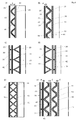
- (A) to (F) are axial sectional views of a main part showing a modified example of a flow reactor according to an embodiment of the present invention, respectively.
- FIGS. 2 and 4 (A) to 4 (F) indicate the axial direction.
- the fluid containing the substance to be processed in the reaction will be described as the reaction fluid F1.
- the reaction fluid F1 is composed of, for example, two fluids, each fluid is described as a reaction fluid F1 (A) and a reaction fluid F1 (B). This will be described as the reaction fluid F1.
- the reaction fluid F1 is composed of one fluid, or when it is composed of two or more fluids, it means a fluid after merging in which two or more fluids are merged.
- the heat medium that exchanges heat with the reaction fluid F1 will be described as the second fluid F2.
- another heat medium that exchanges heat with the reaction fluid F1 will be described as the third fluid F3.
- reaction fluid F1 various fluids such as gas, liquid, slurry, and highly viscous liquid can be exemplified.
- second fluid F2 and the third fluid F3 are heat media for heating such as steam and hot water, but heat media for cooling may also be used.
- the flow reactor according to the first embodiment shown in FIG. 1 includes an inner cylinder 10 and an outer cylinder 20 arranged concentrically, and is concentrically further inside the inner cylinder 10 as needed. It includes an arranged third cylinder 30.
- a heat transfer body 41 provided so as to spirally orbit is arranged on the inner peripheral surface of the outer cylinder 20.
- the space between the inner cylinder 10 and the outer cylinder 20 is divided into two spaces by the heat transfer body 41.
- the inside of the heat transfer body 41 (inside in the radial direction) constitutes the reaction flow path 11 which is the flow path of the reaction fluid F1, and the heat transfer is performed between the two partitioned spaces.
- the outside of the body 41 (outside in the radial direction) constitutes the second flow path 21 which is the flow path of the second fluid F2.
- the heat transfer body 41 is fixed to the inner peripheral surface of the outer cylinder 20 in a state of maintaining airtightness and liquidtightness by welding or the like so that the reactive fluid F1 and the second fluid F2 do not mix with each other.
- the space between the inner cylinder 10 and the outer cylinder 20 is divided into a reaction flow path 11 and a second flow path 21, and the reactive flow path 11 and the second flow path 21 circulate in a spiral shape. It becomes. Heat exchange is performed between the reaction fluid F1 and the second fluid F2 via the heat transfer body 41.
- the inner cylinder 10 and the outer cylinder 20 are detachably assembled, and as shown in FIG. 2, the heat transfer body 41 is separated from the inner cylinder 10 together with the outer cylinder 20 in a separated state. In this separated state, the flow path constituent surface defining the reaction flow path 11 is separated into the inner cylinder 10 side and the outer cylinder 20 side.
- the space between the inner cylinder 10 and the third cylinder 30 constitutes the third flow path 31 for the third fluid F3, and the reaction fluid F1 and the third fluid F3 pass through the inner cylinder 10. Heat exchange takes place between them. Since the flow path body 42 spirally circulates and is fixed to the outer peripheral surface of the third cylinder 30, the third flow path 31 also becomes a spirally circling flow path. (Fixing and separating the cylinder)
- the inner cylinder 10, the outer cylinder 20, and the third cylinder 30 are fixed to each other by a flange portion 40 at the upper end of the cylinder so as to be separable from each other.
- the two flange portions 40 are stacked one above the other with the seal member sandwiched between them, and are detachably assembled and integrated by a detachable fixing member (not shown) such as a bolt.
- the upper ends of the inner cylinder 10 and the third cylinder 30 are fixed to the upper flange portion 40 (detachable as necessary), and the upper end of the outer cylinder 20 is fixed to the lower flange portion 40 (detachable as necessary).
- the inner cylinder 10 and the outer cylinder 20 can be separated by being fixed and separating the upper and lower flange portions 40, 40. Further, the inner cylinder 10 and the third cylinder 30 can be separated by making at least one of the inner cylinder 10 and the third cylinder 30 removable from the upper flange portion 40.
- the heat transfer body 41 is fixed to the inner peripheral surface of the outer cylinder 20 by welding or the like. Therefore, when the heat exchanger is disassembled by disassembling the flange portion 40, the outer cylinder 20 in which the heat transfer body 41 is fixed to the inner peripheral surface and the flow path body 42 on the inner cylinder 10 and the outer peripheral surface are formed. It is separated from the provided third cylinder 30. At that time, since there is nothing that interferes with the heat transfer body 41, the outer cylinder 20 to which the heat transfer body 41 is attached can be pulled out to the lower part of the drawing together with the lower flange portion 40. (About heat transfer body 41)
- the heat transfer body 41 advances in the axial direction between the inner cylinder 10 and the outer cylinder 20 while rotating in a spiral shape, and has a substantially triangular cross-sectional shape in the axial cross-sectional view as shown in FIGS. 1 and 2. ..
- the heat transfer body 41 is fixed to the inner peripheral surface of the outer cylinder 20 by welding or the like.
- the apex angle ⁇ of the substantially triangular shape in the axial cross-sectional view of the heat transfer body 41 increases as the cross-sectional area (flow path area) of the reaction flow path 11 and the second flow path 21 increases.
- the number of circumferences of the spiral in a fixed axial length unit of the cylinder 10 and the outer cylinder 20 is reduced.
- the apex angle ⁇ deviates from 90 degrees, the narrow portions in the reaction flow path 11 and the second flow path 21 increase, so that the possibility of fluid clogging increases.
- the temperature is 30 degrees or more and 125 degrees or less.
- the outer angle (360- ⁇ ) with respect to the apex angle ⁇ of the substantially triangle is 90 degrees or more, and it is appropriate that it is 235 degrees or more and 330 degrees or less.
- a triangle has two hypotenuses intersecting at the apex, but assuming industrial production such as processing of a metal plate, the apex is rounded or has a cross-sectional shape with a length in the axial direction. It is common to be. Therefore, the term "triangle" should be understood not only by the meaning of mathematical triangles but also by the shapes that presuppose these industrial productions. Therefore, it should be understood that the apex angle ⁇ of a substantially triangle means not only the intersection of two hypotenuses but also the intersection of their extension lines.
- the reaction fluid F1 is more likely to be clogged between the heat transfer body 41 and the outer peripheral surface of the inner cylinder 10 as the axial length becomes longer. It is appropriate that the axial length thereof is shorter than the axial length of one oblique side.
- the thickness t of the heat transfer body 41 is 0.2 mm in consideration of the efficiency of heat exchange because heat exchange is performed between the reaction fluid F1 and the second fluid F2 via the heat transfer body 41. It is preferably about 3 mm, more preferably 0.5 mm to 2 mm.
- the thickness of the inner cylinder 10, the outer cylinder 20, and the third cylinder 30 may be the same. However, the inner cylinder 10, the outer cylinder 20, and the third cylinder 30 may be changed in consideration of the strength of acting as a structure, and the present invention is not limited to this.
- the heat transfer body 41 is composed of a three-dimensional shape portion 43 having at least one bent portion (a straight line that is bent at an angle and a bent portion including a curved portion that is curved in an arc shape). It can be said that it is.
- the three-dimensional shape portion 43 has at least one bent portion and has a shape capable of forming a space (reaction flow path 11 and second flow path 21) through which a fluid can flow on both the inner surface side and the outer surface side thereof. It is prepared.
- the three-dimensional shape portion 43 is a long body having a shape like a polygonal square cylinder or a cylinder divided along the axial direction thereof. In this example, the three-dimensional shape portion 43 is a square cylinder.
- the three-dimensional shape portion 43 is wound around the inner peripheral surface of the outer cylinder 20, and its upper and lower end sides 46 are fixed to the inner peripheral surface of the outer cylinder 20. It is appropriate that the outer angle ⁇ o formed by the three-dimensional shape portion 43 and the inner peripheral surface of the outer cylinder 20 at each of the upper and lower end sides 46 is 90 degrees or more, and 105 ⁇ ⁇ o ⁇ 160 is more preferable. When the three-dimensional shape portion 43 on the end side 46 is curved, the angle is set between the tangent line and the inner peripheral surface of the outer cylinder 20.
- the outer angle of the bent portion of the three-dimensional shape portion 43 is the outer angle (360- ⁇ ) with respect to the apex angle ⁇ of the substantially triangular shape, the three-dimensional shape portion 43 at each of the upper and lower end sides 46, and the inner peripheral surface of the outer cylinder 20. It is called the outer angle ⁇ o. (About the reaction flow path 11)
- the reaction flow path 11 constitutes a flow path having a substantially triangular cross-sectional shape, and is between the heat transfer body 41 that spirally orbits on the inner peripheral surface of the outer cylinder 20 and the outer peripheral surface of the inner cylinder 10. It is a space of the above, and serves as a flow path of the reaction fluid F1 which is the main target of heat exchange.
- the reaction flow path 11 has a bottom surface 12 formed of an outer peripheral surface of the inner cylinder 10, two slopes of the first slope 13 and the second slope 14, and a top portion between the first slope 13 and the second slope 14. Specified by 15.
- the top portion 15 is composed of an inner peripheral surface of the outer cylinder 20, and this portion serves as an axial space between the circumferences of the spiral of the heat transfer body 41. When the heat transfer body 41 has a dense spiral shape so as not to create this axial space, the top portion 15 becomes a point-shaped apex having no length in the axial cross-sectional shape.
- the inner cylinder 10 is a circular cylindrical body in the axial cross-sectional view, and the outer peripheral surface thereof is a cylindrical outer peripheral surface without unevenness.
- the outer cylinder 20 is also a circular cylinder in the axial cross-sectional view, and the inner peripheral surface thereof is a cylindrical cylindrical surface without unevenness.
- the cross-sectional area (flow path area) of the reaction flow path 11 can be increased by lengthening the axial length (a) of the top portion 15, but even if it is lengthened, the heat transfer body 41 directly related to heat exchange can be increased. Since the area does not change, the overall heat exchange rate may decrease. Therefore, it is desirable that the axial length (a) of the top portion 15 is shorter than the axial length (b) of the slopes 13 and 14.
- the first slope 13 and the second slope 14 are preferably linear in the axial cross-sectional view, but may be curved in an arch shape or the like.
- the above-mentioned flow paths having a substantially triangular cross-sectional shape have a shape in which the fluid to be processed or the gas of the reaction fluid F1 or the second fluid F2 is unlikely to accumulate. It is preferable to have. For example, it is preferable to avoid providing a flat horizontal portion or a recess in a part of the flow path unless there is a special purpose.
- the heat transfer body 41 is provided with a gap ( ⁇ ) on the base portion side of a substantially triangular cross section in the axial direction constituting the reaction flow path 11.
- a space is provided between the inner peripheral end of the first slope 13 and the bottom surface 12, and a space is provided between the inner peripheral end of the second slope 14 and the bottom surface 12. It may be carried out without providing this gap ( ⁇ ), and when providing this gap ( ⁇ ), it is appropriate to set it to 4 mm or less.
- the outer cylinder 20 and the inner cylinder 10 can be smoothly separated.
- the gap is too large, the amount of the reaction fluid F1 does not flow spirally but short-passes in the axial direction, and the amount of the fluid flowing increases, which may reduce the efficiency of heat exchange.
- This gap ( ⁇ ) can be understood as the maximum flow path width ( ⁇ ) of the reaction flow path 11 in the radial direction, and the length between the top 15 and the bottom 18 of the reaction flow path 11 is in the radial direction. It can be understood that the maximum flow path width ( ⁇ ) of the reaction flow path 11 in the above is defined.
- the ratio ( ⁇ / ⁇ ) of the maximum flow path width ( ⁇ ) and the minimum flow path width ( ⁇ ) of the reaction flow path 11 is preferably 2 or more, and preferably 10 or more. ..
- the above-mentioned description of the heat transfer body 41 such as the apex angle ⁇ of a substantially triangular shape in the axial cross-sectional view also applies to the reaction flow path 11.
- reaction flow path 11 has a substantially triangular cross section in the axial direction, and since there is no narrow portion that has become a dead end, a highly viscous substance (highly viscous substance) or a slurry that easily sinks is produced. It has a structure that can suppress the occurrence of adhesion.
- the flow path constituent surface that defines the reaction flow path 11 is the inner peripheral surface of the outer cylinder 20 and the radial inner surface of the heat transfer body 41 on the outer cylinder 20 side, and is on the inner cylinder 10 side. Then, it is the outer peripheral surface of the inner cylinder 10. All of these surfaces are configured to be directly exposed without being hidden by other parts when viewed from the radial direction orthogonal to the axial direction.
- the reaction flow path 11 can be cleaned to every corner, and it is easy to check the state when the cleaning is completed.
- the shell-and-tube reactor described in Patent Document 1 described above cleaning is difficult and the cleaning state cannot be easily confirmed.
- each surface that defines the passage path of the reaction fluid F1 such as the reaction flow path 11 can be selected and implemented according to the type of the reaction fluid F1 such as metal. Further, it is preferable that the surface thereof is coated with a corrosion resistant material. Examples of the coating with the corrosion-resistant material include glass lining, fluororesin coating, and ceramic coating.
- the heat transfer body 41 is fixed to the inner peripheral surface of the outer cylinder 20 by welding or the like, and then coated with a corrosion-resistant material, and the outer peripheral surface of the inner cylinder 10 is similarly coated, and then the inner cylinder 10 is coated. Is inserted into the outer cylinder 20 and assembled, the entire inner surface of the reaction flow path 11, that is, the entire flow path constituent surface defining the reaction flow path 11 can be reliably coated. (About the second flow path 21)
- the space outside the heat transfer body 41 in the radial direction (in other words, the space between the heat transfer body 41 and the inner peripheral surface of the outer cylinder 20) constitutes the second flow path 21 having a substantially triangular cross-sectional shape in the axial direction. ..
- the second flow path 21 is located between the bottom surface 22 formed of the inner peripheral surface of the outer cylinder 20, the two slopes of the first slope 23 and the second slope 24, and the first slope 23 and the second slope 24.
- top 25 Specified by top 25.
- the apex 25 may be a point-shaped apex having no length in the axial cross-sectional shape, or may be a linear or curved apex having a length in the axial cross-sectional shape.
- the axial length (a) of the top 25 is shorter than the axial length (b) of the slopes 23 and 24.
- the first slope 23 and the second slope 24 are preferably linear in the axial cross-sectional view, but may be curved in an arch shape or the like.
- the above-mentioned description of the heat transfer body 41 such as the apex angle ⁇ of a substantially triangular shape in the axial cross-sectional view also applies to the second flow path 21.
- the second flow path 21 is a closed space in the axial cross-sectional view, so that the closed state is maintained only by separating the inner cylinder 10 and the outer cylinder 20. ..
- a heat medium such as water vapor, hot water, cold water, or nitrogen gas is usually passed through the second flow path 21 as the second fluid F2, unlike the reaction flow path 11, there is little possibility that the fluid or the like adheres.
- a plate-shaped flow path body 42 extending spirally is fixed to the outer peripheral surface of the third cylinder 30 by welding or the like, whereby the third flow path 31 becomes a spiral space.
- the circumferential direction of the third flow path 31 may be the same as the orbital direction of the reaction flow path 11 and the second flow path 21, or may be different (for example, clockwise and counterclockwise). ..
- the third flow path 31 is maintained in a closed state unless the inner cylinder 10 and the third cylinder 30 are separated.
- a heat medium such as water vapor, hot water, cold water, or nitrogen gas is usually passed through the third flow path 31 as the third fluid F3, unlike the reaction flow path 11, there is little possibility that the fluid or the like adheres. (About inflow and outflow)
- the inner cylinder 10, the outer cylinder 20, and the third cylinder 30 are provided with a dome-shaped bottom portion 18, a bottom portion 28, and a bottom portion 34, respectively.
- the space between the bottom 18 of the inner cylinder 10 and the bottom 28 of the outer cylinder 20 is connected to the lower part of the spiral reaction flow path 11, and is between the bottom 18 of the inner cylinder 10 and the bottom of the third cylinder 30.
- the space is connected to the lower part of the spiral third flow path 31.
- the lower end of the reaction flow path 11 in FIG. 1 is conducting with the external flow path via the inflow portion 16.
- the inflow portion 16 is implemented as if a T-shaped connecting pipe is attached to a through hole opened in the bottom 28 of the outer cylinder 20.
- the T-shaped connecting pipe consists of a branch pipe and a confluence where the branch pipes meet.
- a mixer 101 such as a static mixer or various continuous mixers is used at the confluence of the T-shaped connecting pipe. May be arranged.
- the upper end of the reaction flow path 11 is conducting with the external flow path via the outflow portion 17.
- the outflow portion 17 is implemented as if a connecting pipe is attached to a through hole opened in the flange portion 40.
- the reaction fluids F1 (A) and F1 (B) are introduced from the branch pipes of the T-shaped connecting pipes constituting the inflow path 16, respectively, merge into the same flow path at the confluence, and the reaction fluid F1 after merging. However, it flows into the spiral reaction flow path 11 and rises while spirally swirling, and flows out from the outflow portion 17 to the outside.
- the upper end of the second flow path 21 is conducting with the external flow path via the inflow portion 26.
- the inflow portion 26 is implemented as if a connecting pipe is attached to a through hole opened in the outer cylinder 20.
- the lower end of the second flow path 21 is conducting with the external flow path via the outflow portion 27.
- the outflow portion 27 is implemented as if a connecting pipe is attached to a through hole opened in the outer cylinder 20.
- the second fluid F2 flows from the inflow portion 26 into the spiral second flow path 21, descends spirally, and flows out from the outflow portion 27 to the outside.
- the upper end of the third flow path 31 is conducting with the external flow path via the inflow portion 32.
- the inflow portion 32 is implemented as if a connecting pipe is attached to a through hole opened in the flange portion 40.
- the lower end of the third flow path 31 is conducting with the external flow path via the outflow portion 33.
- the outflow portion 33 is implemented as if a connecting pipe is attached to a through hole opened in the center of the bottom portion 34, and this connecting pipe is formed in the outflow portion 17 or the second flow path of the reaction flow path 11.
- the inside of the tubular space inside the third cylinder 30 is extended until the position in the axial direction with the inflow portion 26 of the 21 is substantially the same height.
- the third fluid F3 flows into the spiral third flow path 31 from the inflow section 32, descends spirally, and flows out from the outflow section 33 to the outside. It should be noted that the inflow portion and the outflow portion of each flow path can be reversed.
- each surface that defines the passage path of the second fluid F2 and the third fluid F3, such as the second flow path 21 and the third flow path 31, depends on the type of the second fluid F2 and the third fluid F3 such as metal. Although it can be selected and carried out, it is also preferable to coat the surface with a corrosion-resistant material. Examples of the coating with the corrosion-resistant material include glass lining, fluororesin coating, and ceramic coating. (Second Embodiment)
- FIG. 3 shows an axial sectional view of the flow reactor according to the second embodiment.
- the flow reactor according to the first embodiment is different from the flow reactor according to the first embodiment in that the third cylinder 30 is arranged outside the outer cylinder 20.
- the differences will be mainly explained, and the above description of the first embodiment can be applied to the matters not explained.
- three cylinders, an inner cylinder 10, an outer cylinder 20, and a third cylinder 30, are arranged concentrically toward the outside in the radial direction.
- the inner cylinder 10 and the upper end of the heat transfer body 41 are attached to the upper flange 40 (detachable as necessary), and the upper end of the outer cylinder 20 is attached to the lower flange 40 (detachable as necessary). It is attached, and both flange portions 40, 40 are joined vertically so as to be separable and disassembled.
- the upper end of the third cylinder 30 is joined to the outer peripheral surface of the outer cylinder 20 near the upper end by welding or the like, and the lower end of the third cylinder 30 is joined to the outer peripheral surface of the bottom 28 of the outer cylinder 20 by welding or the like.
- the space on the inner surface side of the heat transfer body 41 in other words, the space between the heat transfer body 41 and the inner cylinder 10, is the second flow path 21, and the space on the outer surface side of the heat transfer body 41, in other words, the heat transfer body.
- the space between the body 41 and the outer cylinder 20 is the reaction flow path 11, and the space between the outer cylinder 20 and the third cylinder 30 is the third flow path 31.
- the three-dimensional shaped portions 43 having a substantially triangular cross-sectional shape in the axial cross-sectional view are connected and integrated via a tubular portion 44 having a flat plate shape.
- the heat transfer body 41 also has a tubular shape as a whole, and the shape of the tubular wall surface has a concavo-convex shape including a three-dimensional shape portion 43 and a flat portion 44.
- the flat portion 44 advances in the axial direction while rotating in a spiral shape.
- the reaction flow path 11 has a bottom surface 12 formed by the inner peripheral surface of the outer cylinder 20, two slopes of the first slope 13 and the second slope 14, and a top portion between the first slope 13 and the second slope 14.
- the apex 15 is composed of a flat portion 44 and is a linear apex having a length in the axial cross-sectional shape, but may be a point-shaped apex having no length.
- the second flow path 21 has a bottom surface 22 formed by the outer peripheral surface of the inner cylinder 10, two slopes of the first slope 23 and the second slope 24, and a top 25 between the first slope 23 and the second slope 24.
- the top 25 may be a point-shaped apex having no length in the axial cross-sectional shape, or may be a linear top having a length.
- a plate-shaped flow path body 42 extending spirally is fixed to the inner peripheral surface of the third cylinder 30 by welding or the like, whereby the third flow path 31 becomes a spiral space.
- the circumferential direction of the third flow path 31 may be the same as the orbital direction of the reaction flow path 11 and the second flow path 21, or may be different (for example, clockwise and counterclockwise). .. (About inflow and outflow)
- the outer cylinder 20, the third cylinder 30, and the heat transfer body 41 each have a dome-shaped bottom 28, a bottom 34, and a bottom 45, but the inner cylinder 10 does not have a dome-shaped bottom, and the bottom end thereof is provided. It is fixed to the inner surface side of the bottom 45 of the heat transfer body 41 by welding or the like.
- the lower end of the reaction flow path 11 is conducting with the external flow path via the inflow portion 16.
- the inflow portion 16 is implemented as if a connecting pipe is attached to a through hole opened in the bottom portion 28 of the outer cylinder 20.
- the reaction catalyst 200 may be coordinated to the dome-shaped bottom together with the catalyst holding plate 201. In this case, there is also an effect that operations such as replacement of the reaction catalyst 200 are easy. In addition, the catalyst holding plate 201 prevents the reaction catalyst 200 from flowing out.
- the upper end of the reaction flow path 11 is conducting with the external flow path via the outflow portion 17.
- the outflow portion 17 is implemented as if a connecting pipe is attached to a through hole opened in the flange portion 40.
- the reaction fluid F1 flows from the inflow section 16 into the spiral reaction flow path 11, rises spirally, and flows out from the outflow section 17 to the outside.
- the inflow portion 26 is implemented as if an L-shaped bending connection pipe is attached to a through hole opened in the inner wall surface near the upper end of the inner cylinder 10.
- the lower end of the second flow path 21 is conducting with the external flow path via the outflow portion 27.
- the outflow portion 27 is implemented as if an L-shaped bending connection pipe is attached to a through hole opened in the inner wall surface near the lower end of the inner cylinder 10, but the bending connection pipe is the same as the inflow portion 26.
- the inside of the inner cylinder 10 is extended in the tubular space until the positions in the axial direction are substantially the same height.
- the second fluid F2 flows into the spiral second flow path 21 from the inflow portion 26, descends while spirally swirling, and flows out from the outflow portion 27 to the outside.
- the upper end of the third flow path 31 is electrically connected to the external flow path via the inflow portion 32.
- the inflow portion 32 is implemented as if a connecting pipe is attached to a through hole opened in the outer peripheral surface of the third cylinder 30 near the upper end.
- the lower end of the third flow path 31 is conducting with the external flow path via the outflow portion 33.
- the outflow portion 33 is implemented as if a connecting pipe is attached to a through hole opened near the lower end of the bottom portion 34 of the third cylinder 30.
- the third fluid F3 flows into the spiral third flow path 31 from the inflow section 32, descends spirally, and flows out from the outflow section 33 to the outside. It should be noted that the inflow portion and the outflow portion of each flow path can be reversed. (Separation of cylinder)
- the outer cylinder 20 to which the third cylinder 30 is joined is connected to the inner cylinder. It can be separated into the 10 and the heat transfer body 41, and the outer cylinder 20 to which the third cylinder 30 is joined can be pulled out to the lower part of the drawing together with the lower flange portion 40. As a result, the reaction flow path 11 is separated into two inside and outside, and the flow path constituent surface defining the reaction flow path 11 is separated into the inner cylinder 10 side and the outer cylinder 20 side.
- the flow path constituent surface that defines the reaction flow path 11 is the inner peripheral surface of the outer cylinder 20 on the outer cylinder 20 side, and the radial outer surface of the heat transfer body 41 on the inner cylinder 10 side. All of these surfaces are configured to be directly exposed without being hidden by other parts when viewed from the radial direction orthogonal to the axial direction. Therefore, as in the first embodiment, the reaction flow path 11 is in a state of being extremely easy to clean.
- the outer angle ⁇ o is the angle formed by the three-dimensional shape portion 43 and the outer cylinder 20, but in this embodiment, the outer angle ⁇ o is formed by the three-dimensional shape portion 43 and the flat portion 44. It becomes the angle to make. In either case, since the outer angle ⁇ o is an obtuse angle of 90 degrees or more, in the separated state, it is released to a state where there is no narrow portion, so that the reaction flow path 11 is extremely easy to clean, and the cleaning state. It is also easy to confirm. (About Fig. 4)
- the present invention can be implemented with various modifications in addition to the above-described embodiment. Examples of these changes will be described with reference to FIG.
- the heat transfer body 41 may be arranged on the outer peripheral surface of the inner cylinder 10 as shown in FIG. 4 (A), or may be arranged on the inner peripheral surface of the outer cylinder 20 as shown in FIG. 4 (B). I do not care. Further, the heat transfer body 41 may have the three-dimensional shape portion 43 fixed to the peripheral surface of the cylinder without the flat portion 44, or the heat transfer body 41 includes the three-dimensional shape portion 43 and the flat portion 44 to form a tubular shape as a whole. It doesn't matter.
- the radial width S in the space between the inner cylinder 10 and the outer cylinder 20 is preferably 4 mm to 75 mm, more preferably 10 mm to 50 mm.
- FIG. 4B is a modified example of the second embodiment.
- the top 25 of the heat transfer body 41 and the outer peripheral surface of the inner cylinder 10 face each other, whereas in this modification, the top 25 of the heat transfer body 41 is the inner circumference of the outer cylinder 20. It faces the face.
- a gap (d) is provided between the outer peripheral surface of the flat portion 44 of the heat transfer body 41 and the inner peripheral surface of the outer cylinder 20, in other words, the end side 46 and the outer side of the three-dimensional shape portion 43.
- a space is provided between the cylinder 20 and the inner peripheral surface of the cylinder 20. This may be carried out without providing the gap (d), but it is appropriate that the gap (d) is 3 mm or less.
- a gap in other words) between the axially adjacent orbits of the second flow path that orbits spirally, that is, between the axially adjacent substantially triangular cross-sectional shapes and the substantially triangular cross-sectional shapes.
- d is provided. This may be carried out without providing the gap (d), and when the gap (d) is provided, it is applicable that the gap (d) is 3 mm or less in the radial direction.
- the second flow path 21 can be expanded by providing this gap (d), but if the gap is too large, the second fluid F2 does not flow spirally and short-passes in the axial direction. The amount of fluid flowing increases, which may reduce the efficiency of heat exchange.
- the third cylinder 30 may be arranged and fixed outside the outer cylinder 20 as shown in FIG. 4 (C), or may be arranged inside the inner cylinder 10 as shown in FIG. 4 (D). It may be fixed, or it may be carried out only in the reaction flow path 11 and the second flow path 21 without providing the third cylinder 30.
- two sets of heat transfer bodies 41 may be used.
- one heat transfer body 41 can be fixed to the outer peripheral surface of the inner cylinder 10, and the other heat transfer body 41 can be fixed to the inner peripheral surface of the outer cylinder 20.
- the reaction flow path can be separated from the inner cylinder 10 and the outer cylinder 20. 11 is in a state of being separated into two inside and outside, and the flow path constituent surface defining the reaction flow path 11 is separated into the side of the inner cylinder 10 and the side of the outer cylinder 20.
- the flow path constituent surface that defines the reaction flow path 11 is the inner surface of the heat transfer body 41 in the radial direction on the side of the outer cylinder 10, and the outer surface of the heat transfer tube 41 in the radial direction on the side of the inner cylinder 20. is there. These surfaces are configured to be directly exposed without being hidden by other parts when viewed from the radial direction orthogonal to the axial direction.
- the space between one heat transfer body 41 and the inner cylinder 10 and the space between the other heat transfer body 41 and the outer cylinder 20 form a second flow path and a third flow path.
- the two sets of heat transfer bodies 41 are arranged so that the tops of substantially triangular cross sections in the axial direction face each other, but the pitches of the two sets may be shifted.
- FIG. 4F is a modification of the second embodiment, in which the fourth cylinder 50 is arranged concentrically inside the inner cylinder 10 and in the space between the inner cylinder 10 and the fourth cylinder 50.
- the heat transfer body 41 may be arranged, and a plurality of heat transfer bodies 41 can be arranged in this way.
- the inner cylinder 10 and the fourth cylinder 50 arranged concentrically the inner cylinder 10 is arranged outside the fourth cylinder 50 and the fourth cylinder 50 is the inner cylinder 10 when viewed in terms of the inside and outside in the radial direction. Since it is arranged inside, the inner cylinder 10 corresponds to the outer cylinder 20, and the fourth cylinder 50 corresponds to the inner cylinder 10. From this, in FIG. 4 (F), there are two spaces formed concentrically between the inner cylinder 10 and the outer cylinder 20 arranged concentrically, and they are arranged concentrically. A plurality of spaces formed between the inner cylinder and the outer cylinder can be provided concentrically.
- the inner cylinder 10 side and the outer cylinder 20 side can be assembled so that they can be separated only by moving in the axial direction (vertical direction) without rotating.
- the heat transfer body 41 has a size that does not interfere with other parts when moving in the axial direction (vertical direction).
- the maximum outer diameter of the heat transfer body 41 is It is set smaller than the inner diameter of the outer cylinder 20.
- the minimum inner diameter of the heat transfer body 41 is set to be larger than the outer diameter of the inner cylinder 20.
- the present invention can also be implemented as a substantially conical cylinder whose radius changes as the inner cylinder 10 and the outer cylinder 20 move in the axial direction.
- the inner cylinder 10 can be separated from the outer cylinder 20 by moving the inner cylinder 10 in the upward direction in the drawing, when the heat transfer body 41 is fixed to the inner cylinder 10 side, each of them is orthogonal to the axial direction.
- the maximum outer diameter of the heat transfer body 41 in the cross section is set to be smaller than the inner diameter of the outer cylinder 20 above the cross section.
- the minimum inner diameter of the heat transfer body 41 in each cross section orthogonal to the axial direction is set to be larger than the outer diameter of the inner cylinder 20 above the cross section. Will be done.
Abstract
適正な温度管理の下で反応を進行させることができ、伝熱部に反応用流体や発生ガスが滞留することを抑制でき、分解可能で洗浄性が良く、コーティングやライニングの施工も可能なフローリアクターの提供を図る。同芯の内筒10と外筒20の間に形成される空間内に反応用流路11と第二流路21との2つの流路が設けられたフローリアクターである。内筒10と外筒20との間に螺旋状伝熱体41が配置され、螺旋状伝熱体41は、軸方向断面図において断面形状が略三角形である。螺旋状伝熱体41によって前記空間が反応用流路11と第二流路21とに区画され、反応用流路11内を流れる反応用流体F1と第二流路21内を流れる熱媒F2との間で螺旋状伝熱体41を介して熱交換が行われる。
Description
本願発明は、フローリアクター、特に反応用流体を流すための螺旋状に周回する反応用流路を備えたフローリアクターに関するものである。
化学及び医薬品製造の工程やトナーやインクジェット等の反応工程には急冷や高速加熱もしくは精密温度制御等の要求が多い。また出来るだけ必要な設置スペースを小さくし、機器自体の大きさも小型化する要求があり、熱交換器の高性能化が求められている。そして付着が少なく洗浄性に優れ、耐圧性、耐食性、かつ低コストであるフローリアクターが要求される。
従来、特許文献1に開示されているように、複数のステージを持つシェルアンドチューブリアクターが知られている。このリアクターは少なくとも2つのタイプの領域を備え、両者は、システムの要求に応じて、システムから熱を除去またはシステムへ熱を供給するのに寄与する。リアクターは反応領域のグループを備え、これは反応を促進するための触媒が備えられ、また同時に熱を除去または供給するチューブを備える。
ところがこの特許文献1の何れかに記載のにあっては、チューブ内に付着等が発生した場合、洗浄がし難いし、洗浄できたか否かなど洗浄状態が簡単には確認できない。
また、シェル側の熱媒の保有量が多く、オーバーシュートやアンダーシュートの発生が起こりやすく基本的には古典的な熱交換器であるため総括伝熱係数を画期的に増やすことが難しい。さらにチューブシートにチューブが取り付けられているため、熱に対する膨張と伸縮を繰り返す反応には、採用しづらい。また、細管状の伝熱管の内部にコーティングやライニングの施工は実質的に不可能であるし、その構造上他の流路においても耐食材のコーティングやライニングの施工が難しく、耐食性などの観点からも改善が求まられている。特に前記伝熱管内を耐食材でコーティングやライニングすることは実質的に不可能であり、たとえできたとしても量産性が悪くコスト面から実用性のない物とならざるを得ない。
特許文献2には、複数の供給路量を通して1本の反応流路に合流し、これらの流体を流通させつつ反応を行うマイクロリアクターで、反応流路は丸棒上の芯部材の外周面と断面円形な内周面を有する外筒部材の内周面の何れか一方に螺旋ネジを切って芯部材の外周面と外筒部材の内周面を密着篏合させることにより螺旋状流路として形成されている事を特徴とすることが記載されている。しかしながら伝熱面積が余りにも小さく、せっかく切ったネジ状壁面が直接の熱交換面に用いられず、フローリアクターとして必須の伝熱抵抗を出来るだけ減らして総括伝熱係数を増加させるような観点を持っていない。また、微少量の反応に用いられるマイクロリアクターに特化されており、大型化を行う装置として設計されていない。スケールアップは難しいが、このまま大型化されたとしても分解性や洗浄性等の問題が多いし、精密温度制御等が実現出来ない。
特許文献3には、螺旋特徴を持つ少なくとも二つの同心チューブを備えているチューブ状流れモジュールで、内側チューブは、外側チューブの内側に同軸に配されており、内側チューブの最大直径は外側チューブの最小直径よりも大きく、内側チューブと外側チューブとの間の空間が流体の流れ経路になるチューブ状流れモジュールが記載されている。螺旋特徴を有している外側および内側チューブは、スクリューとナットのように係合され、螺旋特徴はねじのように作用することから、すなわちネジ状篏合を持っているチューブ状流れモジュールである。このチューブ状流れモジュールは、平均流れ方向は軸方向にあり改良プラグ流れ状況を作り出すものである(特許文献段落00018参照)。よって特許文献3のチューブ状流れモジュールは、螺旋流の向流流れが可能なものではなく、
特許文献2と同じように大型化には向いていないし、精密温度制御も難しい。
特許文献2と同じように大型化には向いていないし、精密温度制御も難しい。
上記に鑑み本発明の課題は、適正な温度管理の下で、即ち反応用流体が温度制御された状態で、反応用流体の反応処理を進行させることができるフローリアクターを提供することにある。
本発明の他の課題は、反応を促進させて反応時間の短縮を図ることができるフローリアクターを提供することにある。
本発明のさらに他の課題は、伝熱部に反応用流体や発生ガスが滞留することを抑制するのに適した構造を有するフローリアクターを提供することにある。
本発明の他の課題は、洗浄性の良いフローリアクターを提供することにある。
本発明のさらに他の課題は、分解可能なフローリアクターを提供することである。
また本発明はコーティングやライニングの施工も可能なフローリアクターを提供することを課題とする。
本発明のさらに他の課題は、伝熱部に反応用流体や発生ガスが滞留することを抑制するのに適した構造を有するフローリアクターを提供することにある。
本発明の他の課題は、洗浄性の良いフローリアクターを提供することにある。
本発明のさらに他の課題は、分解可能なフローリアクターを提供することである。
また本発明はコーティングやライニングの施工も可能なフローリアクターを提供することを課題とする。
本発明は、反応用流体を流すための螺旋状に周回する反応用流路を備えたフローリアクターにおいて、同芯の内筒と外筒の間に形成される空間内に伝熱体が配置され、前記伝熱体は、螺旋状に周回していると共に軸方向断面図において断面形状が略三角形であり、前記伝熱体によって、前記空間が前記反応用流路と第二流路とに区画されると共に、前記反応用流路内を流れる前記反応用流体と前記第二流路内を流れる熱媒との間で前記伝熱体を介して熱交換が行われることを特徴とするものである。
本発明は、反応用流体を流すための螺旋状に周回する反応用流路を備えたフローリアクターにおいて、同芯の内筒と外筒の間に形成される空間内に螺旋状に周回する伝熱体が配置され、前記伝熱体によって、前記空間が前記反応用流路と第二流路とに区画されると共に、前記反応用流路内を流れる反応用流体と前記第二流路内を流れる熱媒との間で前記伝熱体を介して熱交換が行われるように構成され、前記内筒と前記外筒と前記伝熱管とは前記外筒の側と前記内筒の側とに分離可能に組付けられており、前記外筒の側と前記内筒の側とに分離された状態で、前記反応用流路を規定する流路構成面は、前記外筒の側と前記内筒の側とに分離されると共に、前記反応用流路を規定する前記流路構成面の全ての表面が軸方向と直交する半径方向から見て他の部分に隠れることなく直接露出するように構成されたことを特徴とするものである。
前記内筒と前記外筒との少なくともいずれか一方は、軸方向断面図において円形の筒体とすることが適当である。これによって、断面形状が略三角形の前記伝熱体と、
前記内筒又は前記外筒とによって規定される反応用流路を流れる反応用流体に、螺旋流の向流流れを発生させることができる。
前記内筒又は前記外筒とによって規定される反応用流路を流れる反応用流体に、螺旋流の向流流れを発生させることができる。
また、半径方向における前記反応用流路の最大流路幅(λ)と前記反応用流路の最小流路幅(μ)との比率(λ/μ)が2以上である(2<λ/μ<∞)ものとすることも適当である。これによって、前記内筒又は前記外筒の軸方向に向かう流れよりも、螺旋方向に向かう流れを大きくすることができ、反応用流体の全体としての流れの向きを、螺旋方向とすることができる。
また、本発明は、前記伝熱体は、前記外筒の側と前記内筒の側との何れか一方に固定され、前記外筒の側と前記内筒の側との何れか他方には固定されていないと共に、少なくとも一つの屈曲部分を有してその内面側と外面側との双方に流体を流すことができる空間を形成できる立体形状部を備えたものであり、前記反応用流路を規定する前記流路構成面に現れる全ての前記屈曲部分の外角が90度以上であるものとして実施することができる。
また、本発明は、前記反応用流路は前記反応用流体が溜まる可能性のある水平部を備えていなものとして実施することができる。
また、本発明は、前記反応用流路は前記反応用流体が溜まる可能性のある水平部を備えていなものとして実施することができる。
また、本発明は、前記反応用流路と前記第二流路とはそれぞれ螺旋状に周回しているものであり、軸方向において隣り合う周回と周回との間に隙間を備えないか或いは半径方向に4mm以下の隙間を備えるものとして実施することができる。
また、本発明は、前記反応用流路と前記第二流路とは軸方向断面図において断面形状が、その頂角θが30度以上125度以下である略三角形であるものとして実施することができる。
また、本発明は、前記内筒の側と前記外筒の側は軸方向への移動のみで回転させずとも分離可能に組付けられており、前記伝熱体は前記軸方向への移動の際に他の部分と干渉しないように構成されたものとして実施することができる。
また、本発明は、前記反応用流路と前記第二流路とは軸方向断面図において断面形状が、二つの斜面と底面と頂部とを備えた略三角形であり、前記頂部の軸方向長さ(a)が前記斜面の軸方向長さ(b)よりも短いものとして実施することができる。
また、本発明は、前記反応用流路と前記第二流路との少なくとも何れか一方の前記頂部が前記軸方向に長さ(a)を備えていることにより、前記頂部が前記軸方向に長さ(a)の無い頂点である場合に比べて、流路の断面積が拡大されているものとして実施することができる。
また、本発明は、前記同芯に配置された前記内筒と前記外筒の間に形成される前記空間が同芯上に複数あるものとして実施することができる。
また、本発明は、前記同芯に配置された前記内筒と前記外筒の間に形成される前記空間が同芯上に複数あるものとして実施することができる。
また、本発明は、前記反応用流路を含む前記反応用流体の流れる通過流路と前記第二流路を含む熱媒の流れる通過流路との少なくとも何れか一方が耐食材料でのコーティングがなされているものとして実施することができ、前記耐食材料でのコーティングがグラスライニングもしくはフッ素樹脂コーティング、セラミックコーティングの内の一つであることが好ましい。
本発明は、適正な温度管理の下で、即ち反応用流体が温度制御された状態で、反応用流体の反応処理を進行させることができるフローリアクターを提供することができたものである。
本発明は、反応を促進させて反応時間の短縮を図ることができるフローリアクターを提供することができたものである。
本発明は、伝熱部に反応用流体や発生ガスが滞留することを抑制するのに適した構造を有するフローリアクターを提供することができたものである。
本発明は、洗浄性の良いフローリアクターを提供することができたものである。
本発明は、分解し易い構造を備えたフローリアクターを提供することができたものである。
本発明はコーティングやライニングの施工も可能なフローリアクターを提供することができたものである。
本発明は、反応を促進させて反応時間の短縮を図ることができるフローリアクターを提供することができたものである。
本発明は、伝熱部に反応用流体や発生ガスが滞留することを抑制するのに適した構造を有するフローリアクターを提供することができたものである。
本発明は、洗浄性の良いフローリアクターを提供することができたものである。
本発明は、分解し易い構造を備えたフローリアクターを提供することができたものである。
本発明はコーティングやライニングの施工も可能なフローリアクターを提供することができたものである。
より具体的に説明すると、化学及び医薬品製造の工程やトナーやインクジェット等の反応工程には急冷や高速加熱もしくは精密温度制御等の要求が多い。その対象物すなわち反応用流体は、高粘度液体や微粒子を含むスラリー、付着物質も多く含まれる。また反応工程において蒸発を伴う加熱操作を行うは、発生ガスが滞留すると熱伝導率が発生ガス気単相流と同程度の低いオーダーまで低下する。この現象は、ドライアウトと呼ばれ、伝熱面に沿って流れていた液膜が蒸発して消失し,気相が直接伝熱面に接することにより起こってしまう。またフローリアクターは確実にスケールアップが必要とされ、高性能化はもちろんの事、大型になっても計算通り処理されなければならない。
これらを解決する為に、反応用流体の流速と圧力損失の関係を見直し反応用流体の流速を上げても圧力損失が大きくなり過ぎない構造を有するフローリアクターを提供できたものである。特に反応用流体が高粘度液体や沈降し易いスラリーの場合効果が大きいし、汚れや付着が少ないものである。
また、伝熱面の断面形状を略三角形にすることにより液だまりや発生ガスのたまりが無く、かつ伝熱面積を大きくとる事ができ、反応用流体の物理的性質から伝熱体の断面として略三角形の形状を選択し設計の自由度も有している。
また反応用流体の保有量も少なく急速加熱や急速冷却にも対応しやすく、同時に熱媒や冷媒も同じように保有量が少ない為、機器の小型化や高性能化、制御の容易化が実現できた。
また、反応用流体の流れの場もその送り量を制御することにより、乱流流れや層流流れも自由に決められ、熱媒や冷媒の流路は、乱流流れとしレイノルズ数を大幅に上昇させ、総括伝熱係数の増加により反応速度を著しく向上することが可能である。
本構造上、非常に簡単なため分解や組み立てが容易であり、耐食材料でコーティングやライニングも可能とする。
本構造上、非常に簡単なため分解や組み立てが容易であり、耐食材料でコーティングやライニングも可能とする。
以下図面を参照して本発明の実施の形態に係るフローリアクターについて説明する。なお、図2、図4(A)~(F)に記載の中心線は、軸方向を示している。
(流体)
(流体)
実施の形態では、反応の処理対象となる物質が含まれている流体を反応用流体F1として説明する。反応用流体F1が例えば2流体から構成される場合、それぞれの流体を反応用流体F1(A)と反応用流体F1(B)として説明し、両者が合流している場合は合流後の流体を反応用流体F1として説明する。以下、反応用流体F1は1流体で構成されているか、2流体以上で構成される場合には2流体以上が合流した合流後の流体を言う。また、反応用流体F1に対して熱交換を行う熱媒体を第二流体F2として説明する。さらに、反応用流体F1に対して熱交換を行う他の熱媒体を第三流体F3として説明する。
この反応用流体F1としては、気体や液体やスラリーや高粘性液体など様々な流体を例示することができる。第二流体F2及び第三流体F3には、水蒸気や温水などの加温用の熱媒体を例示することができるが、冷却用の熱媒体であっても構わない。
(第1の実施の形態の概要)
(第1の実施の形態の概要)
図1に示す第1の実施の形態に係るフローリアクターは、同芯に配置された内筒10と外筒20とを備えたもので、必要に応じて内筒10のさらに内側に同芯に配置された第3筒30を備えている。
外筒20の内周面には螺旋状に周回するように設けられた伝熱体41が配置されている。
外筒20の内周面には螺旋状に周回するように設けられた伝熱体41が配置されている。
内筒10と外筒20の間の空間は、伝熱体41によって二つの空間に区画される。区画された二つの空間のうち伝熱体41の内側(半径方向の内側)が、反応用流体F1の流路である反応用流路11を構成し、区画された二つの空間のうち伝熱体41の外側(半径方向の外側)が、第二流体F2の流路である第二流路21を構成する。
伝熱体41は、外筒20の内周面に対して溶接などによって気密性および液密性を保った状態で固定されることで、反応性流体F1と第二流体F2とが混合しないように、内筒10と外筒20の間の空間を反応用流路11と第二流路21とに区画し、反応性流路11と第二流路21とが螺旋状に周回する流路となる。この伝熱体41を介して反応用流体F1と第二流体F2との間で熱交換が行われる。
内筒10と外筒20は分離可能に組付けられており、図2に示すように、分離した状態で、伝熱体41は外筒20と共に、内筒10と分離される。この分離状態で、反応用流路11を規定する流路構成面は、内筒10の側と外筒20の側とに分離される。
またこの例では、内筒10と第3筒30の間の空間が第三流体F3のための第三流路31を構成し、内筒10を介して反応用流体F1と第三流体F3との間で熱交換が行われる。なお第3筒30の外周面には流路体42が螺旋状に周回して固定されているため、第三流路31も螺旋状に周回した流路となる。
(筒の固定と分離)
(筒の固定と分離)
内筒10、外筒20及び第3筒30は、筒上端のフランジ部40で互いに分離可能に固定されている。この例では2枚のフランジ部40がシール部材を挟んで上下に重ねられ、ボルトなどの着脱可能な固定部材(図示ぜず)によって分離可能に組付けられて一体化されている。上部のフランジ部40には内筒10と第3筒30の上端が(必要に応じて着脱可能に)固定され、下部のフランジ部40には外筒20の上端が(必要に応じて着脱可能に)固定され、上下2枚のフランジ部40、40を分離することによって、内筒10と外筒20を分離することができる。さらに内筒10と第3筒30の少なくともいずれか一方を、上部のフランジ部40に対して着脱可能にしておくことによって、内筒10と第3筒30を分離することもできる。
前述のように、伝熱体41は外筒20の内周面に溶接などによって固定されている。従って、フランジ部40での組付けを解いて熱交換器を分解すると、内周面に伝熱体41が固定されたままの外筒20と、内筒10及び外周面に流路体42を備えた第3筒30とに分離される。その際、伝熱体41に対して干渉するものがないため、伝熱体41の付いた外筒20を下部のフランジ部40と共に図の下方に引き抜くことができる。
(伝熱体41について)
(伝熱体41について)
伝熱体41は、螺旋状に周回しながら内筒10と外筒20の間を軸方向に進むもので、図1及び図2に示すように軸方向断面図において断面形状が略三角形である。この実施の形態では、伝熱体41は外筒20の内周面に溶接などによって固定されている。
上記の伝熱体41の軸方向断面図における略三角形の頂角θは、これが大きくなるに従い、反応用流路11及び第二流路21の断面積(流路面積)が大きくなるが、内筒10と外筒20の一定の軸方向長さ単位における螺旋の周回数が減少する。また、頂角θが90度から離れるに従って、反応用流路11と第二流路21における狭隘な部分が増えるため、流体の詰まりが生ずるおそれが高くなるため、これらを勘案すると頂角θは30度以上125度以下である事が適当である。
なお前記略三角形の頂角θに対する外角(360-θ)は、90度以上であり、235度以上330度以下である事が適当である。
なお前記略三角形の頂角θに対する外角(360-θ)は、90度以上であり、235度以上330度以下である事が適当である。
三角形は数学的な意味では、頂点で2斜辺が交わるが、金属板の加工など工業的な生産を前提とすれば、頂点にはアールが付されたり、軸方向に長さのある断面形状となるのが一般的である。したがって略三角形とは、数学的な三角形の意味だけではなくこれらの工業的生産を前提とした形状を含めて理解されるべきである。従って略三角形の頂角θは、二つの斜辺の交点のみならずそれらの延長線の交点を意味すると理解すべきである。なお、軸方向に長さのある断面形状となる場合、その軸方向長さが長くなるに従って、伝熱体41と内筒10の外周面との間に反応用流体F1が詰まる恐れが高まるため、その軸方向長さは、1つの斜辺の軸方向長さよりも短いことが適当である。
次に、伝熱体41の厚みtは、伝熱体41を介して反応用流体F1と第二流体F2との間で熱交換が行われるので、熱交換の効率を考えて、0.2mm~3mmであることが好ましく、0.5mm~2mmであることがより好ましい。内筒10や外筒20、第3筒30の厚みも同様としてもよい。但し、内筒10や外筒20、第3筒30が構造体として作用する強度を考えて変更してもよく、これに限られない。
この伝熱体41は、少なくとも一つの屈曲部分(直線が角度を持って曲がっているものの他、弧状に湾曲している湾曲部分を含めて屈曲部分と言う)を有する立体形状部43から構成されているとも言える。立体形状部43は、少なくとも一つの屈曲部分を有してその内面側と外面側との双方に流体を流すことができる空間(反応用流路11と第二流路21)を形成できる形状を備えたものである。具体的には立体形状部43は、多角形の角筒や円筒をその軸方向に沿って割ったような形状を備えた長尺状体であり、この例では立体形状部43は、四角筒を、その軸方向に沿って、断面四角形の対角線上で割ったような形状を備えた長尺状体である。立体形状部43は、外筒20の内周面に巻き付けられて、その上下の端辺46が外筒20の内周面に固定されている。上下の端辺46それぞれにおける立体形状部43と外筒20の内周面とがなす外角θoは、90度以上であることが適当であり、105≦θo≦160がより好ましい。なお、端辺46における立体形状部43が湾曲している場合には、その接線と外筒20の内周面とがなす角度とする。
なお、立体形状部43の屈曲部分の外角とは、前記略三角形の頂角θに対する外角(360-θ)と上下の端辺46それぞれにおける立体形状部43と外筒20の内周面とがなす外角θoとをいう。
(反応用流路11について)
(反応用流路11について)
反応用流路11は、断面形状が略三角形の流路を構成するもので、外筒20の内周面にて螺旋状に周回する伝熱体41と、内筒10の外周面との間の空間であり、熱交換の主たる対象となる反応用流体F1の流路となる。
この反応用流路11は、内筒10の外周面で構成される底面12と、第1斜面13及び第2斜面14の二つの斜面と、第1斜面13と第2斜面14の間の頂部15によって規定される。頂部15は外筒20の内周面で構成されており、この部分では伝熱体41の螺旋の周回間における軸方向の空間となっている。なお、この軸方向の空間が生じないように伝熱体41を密な螺旋状とした場合には、頂部15は軸方向断面形状において長さのない点状の頂点となる。
この実施の形態では、内筒10は、軸方向断面図において円形の円筒体であり、その外周面は凹凸のない円筒状の外周面となっている。また、この例では、外筒20も軸方向断面図において円形の円筒体であり、その内周面は凹凸のない円筒状の円筒面となっている。
この頂部15の軸方向長さ(a)を長くすれば反応用流路11の断面積(流路面積)を増やすことができるが、長くしても熱交換に直接関係する伝熱体41の面積は変わらないため、全体的な熱交換率は低下してしまう恐れがある。そのため、頂部15の軸方向長さ(a)は斜面13、14の軸方向長さ(b)よりも短い方が望ましい。
第1斜面13と第2斜面14とは軸方向断面図において直線状であることが適当であるが、弓状などに湾曲した曲線であっても構わない。ただし、上記の断面形状が略三角形の流路(反応用流路11と第二流路21)は、反応用流体F1や第二流体F2の被処理流体もしくは気体が溜まる可能性のない形状であることが好ましい。例えば平坦な水平部や凹部が流路の一部に設けることは、特別な目的がない限り避ける方が好ましい。
またこの例では、図2に示すように、伝熱体41は、反応用流路11を構成する軸方向の断面略三角形の基底部側に隙間(μ)を備えるものである。言い換えれば、第1斜面13の内周側の端部と底面12との間に空間を備えると共に、第2斜面14の内周側の端部と底面12との間に空間を備える。この隙間(μ)を設けずに実施しても構わないし、この隙間(μ)を設ける場合には4mm以下とすることが適当である。さらに言い換えれば、螺旋状に周回する反応用流路11の、軸方向において隣り合う周回と周回との間、即ち軸方向において隣り合う略三角形の断面形状と略三角形の断面形状との間に隙間(μ)を備える。この隙間(μ)を設けずに実施しても構わないし、隙間(μ)を設ける場合には半径方向に4mm以下とすることが適用である。
この隙間(μ)を設けることによって熱交換器を分解する場合外筒20と内筒10との分離を円滑に行うことができる。ところが、あまりにも大きな隙間とした場合には、反応用流体F1が螺旋状に流れることなく軸方向にショートパスして流れる流体の量が多くなり、熱交換の効率を低下させる恐れが生じる。
この隙間(μ)は、半径方向における反応用流路11の最大流路幅(μ)であると理解できるとともに、反応用流路11の頂部15と底部18との間の長さが半径方向における反応用流路11の最大流路幅(λ)を規定すると理解することができる。ここで、反応用流路11の最大流路幅(λ)と最小流路幅(μ)との比率(λ/μ)は2以上であることが適当であり、10以上であることが好ましい。上記隙間μがない場合(言い換えれば伝熱体41と内筒10が接触している場合)はμ=0となり、λ/μ=∞となる。
なお、軸方向断面図における略三角形の頂角θなどの前述の伝熱体41についての説明は、反応用流路11にも適用される。
なお、軸方向断面図における略三角形の頂角θなどの前述の伝熱体41についての説明は、反応用流路11にも適用される。
この反応用流路11には、反応用流体F1として気体や液体やスラリーや高粘性液体など様々な流体が流れることが想定される。その際、流体の種類によっては反応用流路11中に高粘度の物質(高粘稠物)や沈降し易いスラリーが付着する恐れがある。この実施の形態では反応用流路11が軸方向の断面略三角形をなしていると共に、行き止まりとなった狭隘部分が存在しないため、高粘度の物質(高粘稠物)や沈降し易いスラリーが付着の発生を抑制することができる構造となっている。
また、分解清掃を行う場合にも、内筒10と外筒20とを分離すれば、内筒10の外周面が露出することはもちろん、軸方向の断面略三角形の伝熱体41の全体が外筒20の内周面とともに露出する。
言い換えれば、反応用流路11を規定する流路構成面は、外筒20の側では、外筒20の内周面と伝熱体41の半径方向内側の表面であり、内筒10の側では内筒10の外周面である。これらの全ての表面は、軸方向と直交する半径方向から見て他の部分に隠れることなく直接露出するように構成されている。
従って、反応用流路11を隅々まで清掃することができるし、清掃完了時の状態も確認しやすい。これに対して、前掲の特許文献1に記載のシェルアンドチューブリアクターにあっては、洗浄が困難であるし、洗浄状態が簡単には確認できない。
反応用流路11などの反応用流体F1の通過経路を規定する各面の素材は、金属など反応用流体F1の種類に応じて選択して実施することができる。さらに、その表面を耐食材料でコーティングしておくことが好ましい。耐食材料でのコーティングとしては、グラスライニングもしくはフッ素樹脂コーティング、セラミックコーティングを例示することができる。その際、外筒20の内周面に伝熱体41を溶接などで固定した後で耐食材料でのコーティングを行うとともに、内筒10の外周面に同様のコーティングを行なった後、内筒10を外筒20内に挿入して組付ければ、反応用流路11の内面全体、すなわち反応用流路11を規定する流路構成面全体を確実にコーティングすることができる。
(第二流路21について)
(第二流路21について)
伝熱体41の半径方向の外側の空間(言い換えれば、伝熱体41と外筒20の内周面との間の空間)が、軸方向断面形状略三角形の第二流路21を構成する。この第二流路21は、外筒20の内周面で構成される底面22と、第1斜面23及び第2斜面24の二つの斜面と、第1斜面23と第2斜面24の間の頂部25によって規定される。頂部25は軸方向断面形状において長さのない点状の頂点であっても構わないし、軸方向断面形状において長さのある直線状や曲線状の頂部であっても構わない。頂部25を軸方向断面形状において長さのある直線状や曲線状の頂部とした場合、頂部25の軸方向長さ(a)は斜面23、24の軸方向長さ(b)よりも短いことが望ましい。第1斜面23と第2斜面24とは軸方向断面図において直線状であることが適当であるが、弓状などに湾曲した曲線であっても構わない。
なお、軸方向断面図における略三角形の頂角θなどの前述の伝熱体41についての説明は、第二流路21にも適用される。
なお、軸方向断面図における略三角形の頂角θなどの前述の伝熱体41についての説明は、第二流路21にも適用される。
この第二流路21は、反応用流路11と異なり、軸方向断面図において閉ざされた空間であるため、内筒10と外筒20を分離しただけでは、閉ざされた状態が維持される。ところが第二流路21は通常、水蒸気や温水や冷水や窒素ガスなどの熱媒体が第二流体F2として通されるため、反応用流路11とは異なり流体などの付着が生ずるおそれが少ない。
(第三流路31について)
(第三流路31について)
第3筒30の外周面には螺旋状に伸びる板状の流路体42が溶接などによって固定されており、これによって第三流路31は螺旋状の空間となる。第三流路31の周回方向は、反応用流路11、第二流路21の周回方向と同じであっても構わないし、異なるもの(例えば時計回りと反時計回り)であっても構わない。
この第三流路31は、内筒10と第3筒30を分離しなければ、閉ざされた状態が維持される。ところが第三流路31は通常、水蒸気や温水や冷水や窒素ガスなどの熱媒体が第三流体F3として通されるため、反応用流路11とは異なり流体などの付着が生ずるおそれが少ない。
(流入部及び流出部について)
(流入部及び流出部について)
内筒10、外筒20及び第3筒30はそれぞれドーム状の底部18、底部28及び底部34を備えている。内筒10の底部18と外筒20の底部28との間の空間は螺旋状の反応用流路11の下部につながっており、内筒10の底部18と第3筒30の底部との間の空間は螺旋状の第三流路31の下部につながっている。
図1における反応用流路11の下端は、流入部16を介して外部流路と導通している。この例では、流入部16は外筒20の底部28に開口した貫通孔にT字型の接続管を取り付けたものとして実施されている。T字型の接続管は枝管と枝管が合流する合流部とからなり、図1に示すように、T字型の接続管の合流部にスタティックミキサーや各種連続式ミキサーなどの混合器101を配してもよい。反応用流路11の上端は、流出部17を介して外部流路と導通している。この例では、流出部17はフランジ部40に開口した貫通孔に接続管を取り付けたものとして実施されている。反応用流体F1(A)及びF1(B)は流入路16を構成するT字型の接続管の枝管からそれぞれ導入され、合流部で同一流路に合流し、合流後の反応用流体F1が、螺旋状の反応用流路11内に流入して螺旋状に旋回しながら上昇して流出部17から外部へ流出する。
次に、第二流路21の上端は、流入部26を介して外部流路と導通している。この例では、流入部26は外筒20に開口した貫通孔に接続管を取り付けたものとして実施されている。第二流路21の下端は、流出部27を介して外部流路と導通している。この例では、流出部27は外筒20に開口した貫通孔に接続管を取り付けたものとして実施されている。第二流体F2は、流入部26から螺旋状の第二流路21内に流入して螺旋状に下降して流出部27から外部へ流出する。
次に、第三流路31の上端は、流入部32を介して外部流路と導通している。この例では、流入部32はフランジ部40に開口した貫通孔に接続管を取り付けたものとして実施されている。第三流路31の下端は、流出部33を介して外部流路と導通している。この例では、流出部33は底部34の中央に開口した貫通孔に接続管を取り付けたものとして実施されているが、この接続管は、反応用流路11の流出部17や第二流路21の流入部26と軸方向の位置が略同じ高さになるまで第3筒30の内部の筒状空間内を伸ばされている。第三流体F3は、流入部32から螺旋状の第三流路31内に流入して螺旋状に下降して流出部33から外部へ流出する。
なお、各流路の流入部と流出部は逆にして実施することもできる。
なお、各流路の流入部と流出部は逆にして実施することもできる。
第二流路21、第三流路31など、第二流体F2、第三流体F3の通過経路を規定する各面の素材は、金属など第二流体F2と第三流体F3の種類に応じて選択して実施することができるが、その表面を耐食材料でコーティングしておくことも好ましい。耐食材料でのコーティングとしては、グラスライニングもしくはフッ素樹脂コーティング、セラミックコーティングを例示することができる。
(第2の実施の形態)
(第2の実施の形態)
図3に第2の実施の形態に係るフローリアクターの軸方向断面図を示す。この実施の形態に係るフローリアクターは、第3筒30が外筒20の外側に配置されている点が第一の実施の形態に係るフローリアクターと相違する。以下の説明では、相違する点について中心に説明し、説明を施さない事項については先の第一の実施の形態に関する説明を適用することができる。
この第2の実施の形態に係るフローリアクターでは、半径方向の外側に向けて内筒10、外筒20、第3筒30の3本の筒が同芯状に配置されている。上部のフランジ40には内筒10と伝熱体41の上端が(必要に応じて着脱可能に)取り付けられ、下部のフランジ40には外筒20の上端が(必要に応じて着脱可能に)取り付けられ、両フランジ部40、40が上下に分離分解可能に接合されている。第3筒30の上端は外筒20の上端寄りの外周面に溶接などによって接合され、第3筒30の下端は外筒20の底部28の外周面に溶接などによって接合されている。
伝熱体41の内面側の空間、言い換えれば伝熱体41と内筒10の間の空間が、第二流路21とされており、伝熱体41の外面側の空間、言い換えれば伝熱体41と外筒20の間の空間が、反応用流路11とされており、外筒20と第3筒30の間が第三流路31とされている。
伝熱体41は、軸方向断面図において断面形状が略三角形の立体形状部43同士が、平板状をなす筒状部分44を介して接続され一体化されている。言い換えれば、全体として伝熱体41も筒状をなしており、筒状の壁面の形状が立体形状部43と平坦部分44とを備えた凹凸形状をなしているもので、立体形状部43と平坦部分44とは螺旋状に周回しながら軸方向に進むものである。
(各流路について)
(各流路について)
反応用流路11は、外筒20の内周面によって構成される底面12と、第1斜面13及び第2斜面14の二つの斜面と、第1斜面13と第2斜面14の間の頂部15によって規定される。頂部15は平坦部分44によって構成されており、軸方向断面形状において長さのある線状の頂部であるが、長さのない点状の頂点であっても構わない。
第二流路21は、内筒10の外周面によって構成される底面22と、第1斜面23及び第2斜面24の二つの斜面と、第1斜面23と第2斜面24の間の頂部25によって規定される。頂部25は軸方向断面形状において長さのない点状の頂点であっても構わないし、長さのある線状の頂部であっても構わない。
第3筒30の内周面には、螺旋状に伸びる板状の流路体42が溶接などによって固定されており、これによって第三流路31は螺旋状の空間となる。第三流路31の周回方向は、反応用流路11、第二流路21の周回方向と同じであっても構わないし、異なるもの(例えば時計回りと反時計回り)であっても構わない。
(流入部及び流出部について)
(流入部及び流出部について)
外筒20、第3筒30及び伝熱体41はそれぞれドーム状の底部28、底部34及び底部45を備えているが、内筒10はドーム状の底部を備えておらず、その底端が伝熱体41の底部45の内面側に溶接などによって固定されている。
反応用流路11は、その下端が、流入部16を介して外部流路と導通している。この例では、流入部16は外筒20の底部28に開口した貫通孔に接続管を取り付けたものとして実施されている。
また、図3に示すように、反応用触媒200を触媒保持板201と共にドーム状底部に配位しても良い。この場合反応用触媒200の入れ替えなどの操作が容易である効果もある。また、触媒保持板201により反応用触媒200の流出を防止する。
反応用流路11の上端は、流出部17を介して外部流路と導通している。この例では、流出部17はフランジ部40に開口した貫通孔に接続管を取り付けたものとして実施されている。反応用流体F1は、流入部16から螺旋状の反応用流路11内に流入して螺旋状に上昇して流出部17から外部へ流出する。
次に第二流路21は、その上端が流入部26を介して外部流路と導通している。この例では、流入部26は内筒10の上端寄りの内壁面に開口した貫通孔にL状の屈曲接続管を取り付けたものとして実施されている。第二流路21の下端は、流出部27を介して外部流路と導通している。この例では、流出部27は内筒10の下端寄りの内壁面に開口した貫通孔にL状の屈曲接続管を取り付けたものとして実施されているが、この屈曲接続管は、流入部26と軸方向の位置が略同じ高さになるまで内筒10の内部の筒状空間内を伸ばされている。
第二流体F2は、流入部26から螺旋状の第二流路21内に流入して螺旋状に旋回しながら下降して流出部27から外部へ流出する。
第二流体F2は、流入部26から螺旋状の第二流路21内に流入して螺旋状に旋回しながら下降して流出部27から外部へ流出する。
次に、第三流路31は、その上端が流入部32を介して外部流路と導通している。この例では、流入部32は第3筒30の上端寄りの外周面に開口した貫通孔に接続管を取り付けたものとして実施されている。第三流路31の下端は、流出部33を介して外部流路と導通している。この例では、流出部33は第3筒30の底部34の下端寄りに開口した貫通孔に接続管を取り付けたものとして実施されている。第三流体F3は、流入部32から螺旋状の第三流路31内に流入して螺旋状に下降して流出部33から外部へ流出する。
なお、各流路の流入部と流出部は逆にして実施することもできる。
(筒の分離)
なお、各流路の流入部と流出部は逆にして実施することもできる。
(筒の分離)
上下のフランジ部40、40のボルトなどの着脱可能な接合部材(図示ぜず)による接合を解除して熱交換器を分解すると、第3筒30が接合された外筒20とを、内筒10及び伝熱体41とに分離することができ、第3筒30が接合された外筒20を下部のフランジ部40と共に図の下方に引き抜くことができる。これによって反応用流路11は内外二つに分離された状態となり、反応用流路11を規定する流路構成面は、内筒10の側と外筒20の側とに分離される。反応用流路11を規定する流路構成面は、外筒20の側では、外筒20の内周面であり、内筒10の側では伝熱体41の半径方向外側の表面である。これらの全ての表面は、軸方向と直交する半径方向から見て他の部分に隠れることなく直接露出するように構成されている。従って第1の実施の形態と同じく、反応用流路11は清掃が極めて簡単な状態となる。
第1の実施の形態でおいては、外角θoは立体形状部43と外筒20とがなす角度であったが、この実施の形態においては外角θoは立体形状部43と平坦部分44とがなす角度となる。いずれの場合でも、外角θoが90度以上の鈍角であるため、分離した状態では、狭隘な部分がない状態に解放されるため、反応用流路11の清掃が極めて簡単であるし、清掃状態の確認も容易となる。
(図4について)
本発明は上述の実施の形態の他種々変更して実施することができる。これらの変更例を図4を参照しながら説明する。
(図4について)
本発明は上述の実施の形態の他種々変更して実施することができる。これらの変更例を図4を参照しながら説明する。
伝熱体41は、図4(A)に示すように内筒10の外周面に配置しても構わないし、図4(B)に示すように外筒20の内周面に配置しても構わない。また、伝熱体41は、平坦部分44を備えずに立体形状部43を筒の周面に固定しても構わないし、立体形状部43と平坦部分44を備えて全体として筒状をなすものとしても構わない。
図4(A)に示すように、内筒10と外筒20との間の空間における半径方向の幅Sは、4mm~75mmであることが好ましく、10mm~50mmであることがより好ましい。
この図4(B)は第2の実施の形態の変形例であるとも言える。第2の実施の形態においては伝熱体41の頂部25と内筒10の外周面とが向かい合うものであるに対し、この変形例においては伝熱体41の頂部25が外筒20の内周面と向かい合うものである。この例では、伝熱体41の平坦部分44の外周面と外筒20の内周面との間に隙間(d)を備えるものであり、言い換えれば、立体形状部43の端辺46と外筒20の内周面との間に空間を備える。この隙間(d)を設けずに実施しても構わないが、この隙間(d)は3mm以下とすることが適当である。さらに言い換えれば、螺旋状に周回する第二流路の、軸方向において隣り合う周回と周回との間、即ち軸方向において隣り合う略三角形の断面形状と略三角形の断面形状との間に隙間(d)を備える。この隙間(d)を設けずに実施しても構わないし、隙間(d)を設ける場合には半径方向に3mm以下とすることが適用である。この隙間(d)を設けることによって第二流路21を拡大することができる反面、あまりにも大きな隙間とした場合には、第二流体F2が螺旋状に流れることなく軸方向にショートパスして流れる流体の量が多くなり、熱交換の効率を低下させる恐れが生じる。
次に、第3筒30は、図4(C)に示すように外筒20の外側に配置して固定してもよいし、図4(D)に示すように内筒10の内側に配置し固定してもよいし、また第3筒30設けずに反応用流路11と第二流路21だけで実施しても構わない。
図4(E)に示すように、伝熱体41を2組用いても構わない。この場合一方の伝熱体41は内筒10の外周面に固定され、他方の伝熱体41は外筒20の内周面に固定された形態を示すことができる。2組の伝熱体41、41の間の空間が、反応用流体F1が流れる反応用流路11を構成するようにすれば、内筒10と外筒20とを分離させると反応用流路11は内外二つに分離された状態となり、反応用流路11を規定する流路構成面は、内筒10の側と外筒20の側とに分離される。反応用流路11を規定する流路構成面は、外筒10の側では、伝熱体41の半径方向内側の表面であり、内筒20の側では伝熱管41の半径方向外側の表面である。これらの面は軸方向と直交する半径方向から見て他の部分に隠れることなく直接露出するように構成されている。
一方の伝熱体41と内筒10との間の空間と、他方の伝熱体41と外筒20との間の空間とが、第二流路、第三流路を構成する。なお図4(E)では、2組の伝熱体41は、軸方向断面の略三角形の頂部同士が向かい合うように配置されているが、両者のピッチをずらすなどしても構わない。
図4(F)は第2の実施の形態の変形例であり、内筒10のさらに内側に同芯に第4筒50を配置し、内筒10と第4筒50との間の空間に伝熱体41を配置してもよく、このように複数の伝熱体41を配置することができる。同芯に配置された内筒10と第4筒50においては、半径方向の内外の関係で見ると、内筒10は第4筒50よりも外側に配置され、第4筒50は内筒10よりも内側に配置されていることから、内筒10は外筒20、第4筒50は内筒10に相当する。このことから、図4(F)は、同芯に配置された内筒10と外筒20との間に形成される空間が同芯上に2つあるものであり、同芯に配置された内筒と外筒の間に形成される空間を同芯上に複数備えることができるものである。
以上、何れの例においても、内筒10の側と外筒20の側とは、軸方向(上下方向)への移動のみで回転させずとも分離することができるように組付け可能な形態を備えるものであり、伝熱体41は軸方向(上下方向)への移動の際に他の部分と干渉しない大きさを備えている。具体的には、その半径が一定な円筒形の内筒10及び外筒20の場合、伝熱体41が内筒10の側に固定されているとすると、伝熱体41の最大外径が外筒20の内径よりも小さく設定される。また伝熱体41が外筒20の側に固定されているとすると、伝熱体41の最小内径が内筒20の外径よりも大きく設定される。また、本発明は、内筒10及び外筒20が軸方向に 向かうに従ってその半径が変化する略円錐筒形のものとしても実施することができる。この場合、図の上方向へ内筒10を移動させることにより外筒20と分離できるとすると、伝熱体41が内筒10の側に固定されている場合には、軸方向と直交する各断面における伝熱体41の最大外径が、当該断面より上方の外筒20の内径よりも小さく設定される。また伝熱体41が外筒20の側に固定されているとすると、軸方向と直交する各断面における伝熱体41の最小内径が当該断面より上方の内筒20の外径よりも大きく設定される。
F1 反応用流体
F2 第二流体
F3 第三流体
10 内筒
11 反応用流路
12 底面
13 第1斜面
14 第2斜面
15 頂部
16 流入部
17 流出部
18 底部
20 外筒
21 第二流路
22 底面
23 第1斜面
24 第2斜面
25 頂部
26 流入部
27 流出部
28 底部
30 第3筒
31 第三流路
32 流入部
33 流出部
34 底部
40 フランジ部
41 伝熱体
42 流路体
43 立体形状部
44 平坦部分
45 底部
λ 反応用流路の最大流路幅
μ 隙間(反応用流路の最小流路幅)
d 隙間
F2 第二流体
F3 第三流体
10 内筒
11 反応用流路
12 底面
13 第1斜面
14 第2斜面
15 頂部
16 流入部
17 流出部
18 底部
20 外筒
21 第二流路
22 底面
23 第1斜面
24 第2斜面
25 頂部
26 流入部
27 流出部
28 底部
30 第3筒
31 第三流路
32 流入部
33 流出部
34 底部
40 フランジ部
41 伝熱体
42 流路体
43 立体形状部
44 平坦部分
45 底部
λ 反応用流路の最大流路幅
μ 隙間(反応用流路の最小流路幅)
d 隙間
Claims (12)
- 反応用流体を流すための螺旋状に周回する反応用流路を備えたフローリアクターにおいて、
同芯の内筒と外筒の間に形成される空間内に伝熱体が配置され、
前記内筒と前記外筒との少なくともいずれか一方は、軸方向断面図において円形の筒体であり、
前記伝熱体は、螺旋状に周回していると共に軸方向断面図において断面形状が略三角形であり、
前記伝熱体によって、前記空間が前記反応用流路と第二流路とに区画されると共に、前記反応用流路内を流れる前記反応用流体と前記第二流路内を流れる熱媒との間で前記伝熱体を介して熱交換が行われることを特徴とするフローリアクター。 - 反応用流体を流すための螺旋状に周回する反応用流路を備えたフローリアクターにおいて、
同芯の内筒と外筒の間に形成される空間内に螺旋状に周回する伝熱体が配置され、
前記伝熱体によって、前記空間が前記反応用流路と第二流路とに区画されると共に、前記反応用流路内を流れる反応用流体と前記第二流路内を流れる熱媒との間で前記伝熱体を介して熱交換が行われるように構成され、
前記内筒と前記外筒と前記伝熱管とは前記外筒の側と前記内筒の側とに分離可能に組付けられており、
前記外筒の側と前記内筒の側とに分離された状態で、前記反応用流路を規定する流路構成面は、前記外筒の側と前記内筒の側とに分離されると共に、前記反応用流路を規定する前記流路構成面の全ての表面が軸方向と直交する半径方向から見て他の部分に隠れることなく直接露出するように構成され、
前記反応用流路は、螺旋状に周回する流路であり、
半径方向における前記反応用流路の最大流路幅(λ)と前記反応用流路の最小流路幅(μ)との比率(λ/μ)が2以上である(2<λ/μ<∞)ことを特徴とするフローリアクター。 - 前記伝熱体は、前記外筒の側と前記内筒の側との何れか一方に固定され、前記外筒の側と前記内筒の側との何れか他方には固定されていないと共に、少なくとも一つの屈曲部分を有してその内面側と外面側との双方に流体を流すことができる空間を形成できる立体形状部を備えたものであり、
前記反応用流路を規定する前記流路構成面に現れる全ての前記屈曲部分の外角が90度以上であることを特徴とする請求項2に記載のフローリアクター。 - 前記反応用流路は前記反応用流体が溜まる可能性のある水平部を備えていないことを特徴とする請求項1~3に記載の何れかに記載のフローリアクター。
- 前記反応用流路と前記第二流路とはそれぞれ螺旋状に周回しているものであり、軸方向において隣り合う周回と周回との間に隙間を備えないか或いは半径方向に4mm以下の隙間を備えることを特徴する請求項1~4に記載の何れかに記載のフローリアクター。
- 前記反応用流路と前記第二流路とは軸方向断面図において断面形状が、その頂角θが30度以上125度以下である略三角形であることを特徴とする請求項1~5に記載の何れかに記載のフローリアクター。
- 前記内筒の側と前記外筒の側は軸方向への移動のみで回転させずとも分離可能に組付けられており、前記伝熱体は前記軸方向への移動の際に他の部分と干渉しないように構成されたことを特徴とする請求項1~6に記載の何れかに記載のフローリアクター。
- 前記反応用流路と前記第二流路とは軸方向断面図において断面形状が、二つの斜面と底面と頂部とを備えた略三角形であり、前記頂部の軸方向長さ(a)が前記斜面の軸方向長さ(b)よりも短いことを特徴とする請求項1~7に記載の何れかに記載のフローリアクター。
- 前記反応用流路と前記第二流路との少なくとも何れか一方の前記頂部が前記軸方向に長さ(a)を備えていることにより、前記頂部が前記軸方向に長さ(a)の無い頂点である場合に比べて、流路の断面積が拡大されていることを特徴とする請求項8に記載の何れかに記載のフローリアクター。
- 前記同芯に配置された前記内筒と前記外筒の間に形成される前記空間が同芯上に複数あることを特徴とする請求項1~9の何れかに記載のフローリアクター。
- 前記反応用流路を含む前記反応用流体の流れる通過流路と前記第二流路を含む熱媒の流れる通過流路との少なくとも何れか一方が耐食材料でのコーティングがなされていることを特徴とする請求項1~10の何れかに記載のフローリアクター。
- 前記耐食材料でのコーティングがグラスライニングもしくはフッ素樹脂コーティング、セラミックコーティングの内の一つであることを特徴とする請求項1~11の何れかに記載のフローリアクター。
Priority Applications (6)
| Application Number | Priority Date | Filing Date | Title |
|---|---|---|---|
| US17/782,556 US20230011329A1 (en) | 2019-12-20 | 2019-12-20 | Flow reactor |
| JP2021565315A JP7418030B2 (ja) | 2019-12-20 | 2019-12-20 | フローリアクター |
| CN201980102396.1A CN114728261A (zh) | 2019-12-20 | 2019-12-20 | 流动反应器 |
| EP19956523.5A EP4079398A4 (en) | 2019-12-20 | 2019-12-20 | FLOW REACTOR |
| PCT/JP2019/050217 WO2021124583A1 (ja) | 2019-12-20 | 2019-12-20 | フローリアクター |
| KR1020227011735A KR20220113351A (ko) | 2019-12-20 | 2019-12-20 | 플로우 리액터 |
Applications Claiming Priority (1)
| Application Number | Priority Date | Filing Date | Title |
|---|---|---|---|
| PCT/JP2019/050217 WO2021124583A1 (ja) | 2019-12-20 | 2019-12-20 | フローリアクター |
Publications (1)
| Publication Number | Publication Date |
|---|---|
| WO2021124583A1 true WO2021124583A1 (ja) | 2021-06-24 |
Family
ID=76478697
Family Applications (1)
| Application Number | Title | Priority Date | Filing Date |
|---|---|---|---|
| PCT/JP2019/050217 WO2021124583A1 (ja) | 2019-12-20 | 2019-12-20 | フローリアクター |
Country Status (6)
| Country | Link |
|---|---|
| US (1) | US20230011329A1 (ja) |
| EP (1) | EP4079398A4 (ja) |
| JP (1) | JP7418030B2 (ja) |
| KR (1) | KR20220113351A (ja) |
| CN (1) | CN114728261A (ja) |
| WO (1) | WO2021124583A1 (ja) |
Families Citing this family (3)
| Publication number | Priority date | Publication date | Assignee | Title |
|---|---|---|---|---|
| JP6813233B1 (ja) * | 2019-12-26 | 2021-01-13 | エム・テクニック株式会社 | 熱交換器 |
| KR20220119361A (ko) * | 2019-12-26 | 2022-08-29 | 엠. 테크닉 가부시키가이샤 | 플로우 리액터 |
| CN115382490B (zh) * | 2022-08-17 | 2023-08-22 | 江苏中丽新材料有限公司 | 一种高效脱色絮凝剂的制备设备 |
Citations (11)
| Publication number | Priority date | Publication date | Assignee | Title |
|---|---|---|---|---|
| US2374609A (en) * | 1945-04-24 | Heating apparatus | ||
| US2456775A (en) * | 1944-11-16 | 1948-12-21 | Arthur J Fausek | Heat exchanger |
| US2993682A (en) * | 1957-03-18 | 1961-07-25 | Huet Andre | Heat exchanger tubes |
| US3332446A (en) * | 1964-05-15 | 1967-07-25 | Douglas B Mann | Cryogenic transfer line arrangement |
| US5148861A (en) * | 1991-07-31 | 1992-09-22 | Triangle Research And Development Corporation | Quick disconnect thermal coupler |
| JPH09512894A (ja) * | 1994-05-09 | 1997-12-22 | クヴァルナル エンジニアリング アクティー ゼルスカップ | 熱交換器 |
| JP2000297991A (ja) * | 1999-03-03 | 2000-10-24 | Hde Metallwerk Gmbh | 熱交換器管 |
| JP2005046652A (ja) | 2003-05-30 | 2005-02-24 | Fuji Photo Film Co Ltd | マイクロリアクター |
| US20080315117A1 (en) * | 2006-02-20 | 2008-12-25 | Bayer Technology Services Gmbh | Cleanable Helical Modules |
| JP2012529626A (ja) | 2009-06-09 | 2012-11-22 | ハネウェル・インターナショナル・インコーポレーテッド | 複数ステージ、複数チューブのシェル−アンド−チューブリアクタ |
| JP2015502842A (ja) | 2011-11-08 | 2015-01-29 | アルファ・ラバル・コーポレイト・エービー | チューブモジュール |
Family Cites Families (7)
| Publication number | Priority date | Publication date | Assignee | Title |
|---|---|---|---|---|
| JP2001201275A (ja) * | 2000-01-21 | 2001-07-27 | Daikin Ind Ltd | 二重管式熱交換器 |
| JP2008134003A (ja) * | 2006-11-28 | 2008-06-12 | Luft Wasser Project:Kk | チューブ式熱交換器 |
| EP2406005A2 (en) * | 2009-03-13 | 2012-01-18 | University of Utah Research Foundation | Fluid-sparged helical channel reactor and associated methods |
| US8298493B2 (en) * | 2010-12-17 | 2012-10-30 | Holl Richard A | Heat exchange apparatus |
| WO2013150818A1 (ja) * | 2012-04-05 | 2013-10-10 | シーアイ化成株式会社 | 伝熱管とそれを用いた熱交換器 |
| JP6436529B2 (ja) * | 2014-11-18 | 2018-12-12 | 株式会社アタゴ製作所 | 熱交換器 |
| JP2019007649A (ja) * | 2017-06-21 | 2019-01-17 | 株式会社Soken | 熱交換装置 |
-
2019
- 2019-12-20 JP JP2021565315A patent/JP7418030B2/ja active Active
- 2019-12-20 US US17/782,556 patent/US20230011329A1/en active Pending
- 2019-12-20 CN CN201980102396.1A patent/CN114728261A/zh active Pending
- 2019-12-20 EP EP19956523.5A patent/EP4079398A4/en active Pending
- 2019-12-20 WO PCT/JP2019/050217 patent/WO2021124583A1/ja unknown
- 2019-12-20 KR KR1020227011735A patent/KR20220113351A/ko active Search and Examination
Patent Citations (11)
| Publication number | Priority date | Publication date | Assignee | Title |
|---|---|---|---|---|
| US2374609A (en) * | 1945-04-24 | Heating apparatus | ||
| US2456775A (en) * | 1944-11-16 | 1948-12-21 | Arthur J Fausek | Heat exchanger |
| US2993682A (en) * | 1957-03-18 | 1961-07-25 | Huet Andre | Heat exchanger tubes |
| US3332446A (en) * | 1964-05-15 | 1967-07-25 | Douglas B Mann | Cryogenic transfer line arrangement |
| US5148861A (en) * | 1991-07-31 | 1992-09-22 | Triangle Research And Development Corporation | Quick disconnect thermal coupler |
| JPH09512894A (ja) * | 1994-05-09 | 1997-12-22 | クヴァルナル エンジニアリング アクティー ゼルスカップ | 熱交換器 |
| JP2000297991A (ja) * | 1999-03-03 | 2000-10-24 | Hde Metallwerk Gmbh | 熱交換器管 |
| JP2005046652A (ja) | 2003-05-30 | 2005-02-24 | Fuji Photo Film Co Ltd | マイクロリアクター |
| US20080315117A1 (en) * | 2006-02-20 | 2008-12-25 | Bayer Technology Services Gmbh | Cleanable Helical Modules |
| JP2012529626A (ja) | 2009-06-09 | 2012-11-22 | ハネウェル・インターナショナル・インコーポレーテッド | 複数ステージ、複数チューブのシェル−アンド−チューブリアクタ |
| JP2015502842A (ja) | 2011-11-08 | 2015-01-29 | アルファ・ラバル・コーポレイト・エービー | チューブモジュール |
Non-Patent Citations (1)
| Title |
|---|
| See also references of EP4079398A4 |
Also Published As
| Publication number | Publication date |
|---|---|
| US20230011329A1 (en) | 2023-01-12 |
| EP4079398A4 (en) | 2023-09-06 |
| CN114728261A (zh) | 2022-07-08 |
| KR20220113351A (ko) | 2022-08-12 |
| EP4079398A1 (en) | 2022-10-26 |
| JP7418030B2 (ja) | 2024-01-19 |
| JPWO2021124583A1 (ja) | 2021-06-24 |
Similar Documents
| Publication | Publication Date | Title |
|---|---|---|
| WO2021124583A1 (ja) | フローリアクター | |
| WO2021124582A1 (ja) | 熱交換器 | |
| JP2021105507A (ja) | フローリアクター | |
| EP2232189B1 (en) | Heat exchanger | |
| CN110494208B (zh) | 热交换器和反应器 | |
| JP4343836B2 (ja) | 交差エレメントアセンブリとその製造方法 | |
| US20160025413A1 (en) | Pipe bundle recuperator on a sintering furnace and thermal transfer method having a sintering furnace and having a pipe bundle recuperator | |
| US20040182556A1 (en) | High-performance thermal control ducts | |
| JP6813233B1 (ja) | 熱交換器 | |
| EP4045863A1 (en) | Heat exchanger | |
| EP0699292B1 (en) | Heat exchanger | |
| JPH08126838A (ja) | 槽容器 |
Legal Events
| Date | Code | Title | Description |
|---|---|---|---|
| 121 | Ep: the epo has been informed by wipo that ep was designated in this application |
Ref document number: 19956523 Country of ref document: EP Kind code of ref document: A1 |
|
| ENP | Entry into the national phase |
Ref document number: 2021565315 Country of ref document: JP Kind code of ref document: A |
|
| NENP | Non-entry into the national phase |
Ref country code: DE |
|
| ENP | Entry into the national phase |
Ref document number: 2019956523 Country of ref document: EP Effective date: 20220720 |