WO2021124551A1 - 電流計測装置、蓄電装置 - Google Patents
電流計測装置、蓄電装置 Download PDFInfo
- Publication number
- WO2021124551A1 WO2021124551A1 PCT/JP2019/050109 JP2019050109W WO2021124551A1 WO 2021124551 A1 WO2021124551 A1 WO 2021124551A1 JP 2019050109 W JP2019050109 W JP 2019050109W WO 2021124551 A1 WO2021124551 A1 WO 2021124551A1
- Authority
- WO
- WIPO (PCT)
- Prior art keywords
- current
- resistor
- pair
- detection
- connection point
- Prior art date
- Legal status (The legal status is an assumption and is not a legal conclusion. Google has not performed a legal analysis and makes no representation as to the accuracy of the status listed.)
- Ceased
Links
Images






Classifications
-
- G—PHYSICS
- G01—MEASURING; TESTING
- G01R—MEASURING ELECTRIC VARIABLES; MEASURING MAGNETIC VARIABLES
- G01R1/00—Details of instruments or arrangements of the types included in groups G01R5/00 - G01R13/00 and G01R31/00
- G01R1/20—Modifications of basic electric elements for use in electric measuring instruments; Structural combinations of such elements with such instruments
- G01R1/203—Resistors used for electric measuring, e.g. decade resistors standards, resistors for comparators, series resistors, shunts
-
- G—PHYSICS
- G01—MEASURING; TESTING
- G01R—MEASURING ELECTRIC VARIABLES; MEASURING MAGNETIC VARIABLES
- G01R31/00—Arrangements for testing electric properties; Arrangements for locating electric faults; Arrangements for electrical testing characterised by what is being tested not provided for elsewhere
- G01R31/36—Arrangements for testing, measuring or monitoring the electrical condition of accumulators or electric batteries, e.g. capacity or state of charge [SoC]
- G01R31/382—Arrangements for monitoring battery or accumulator variables, e.g. SoC
-
- Y—GENERAL TAGGING OF NEW TECHNOLOGICAL DEVELOPMENTS; GENERAL TAGGING OF CROSS-SECTIONAL TECHNOLOGIES SPANNING OVER SEVERAL SECTIONS OF THE IPC; TECHNICAL SUBJECTS COVERED BY FORMER USPC CROSS-REFERENCE ART COLLECTIONS [XRACs] AND DIGESTS
- Y02—TECHNOLOGIES OR APPLICATIONS FOR MITIGATION OR ADAPTATION AGAINST CLIMATE CHANGE
- Y02E—REDUCTION OF GREENHOUSE GAS [GHG] EMISSIONS, RELATED TO ENERGY GENERATION, TRANSMISSION OR DISTRIBUTION
- Y02E60/00—Enabling technologies; Technologies with a potential or indirect contribution to GHG emissions mitigation
- Y02E60/10—Energy storage using batteries
Definitions
- the present invention relates to a device for measuring the current of a power storage element.
- a measuring resistor such as a shunt resistor may be used as one of the current measuring devices of the power storage element.
- the following Patent Document 1 describes that a ground terminal is provided on the shunt resistor.
- the current measuring device has a current detection unit that detects the current from the voltage difference of the resistor. There is an allowable value for the input voltage of the current detector. If the input voltage exceeds the permissible value, it will be saturated to the permissible value, and the current measurement accuracy will decrease.
- An object of the present invention is to suppress saturation of input voltage and improve current measurement accuracy.
- the current measuring device for measuring the current of the power storage element is a measuring resistor located on the current path and having a resistor, a pair of detection points located on both sides of the resistor on the current path, and a pair of detection points. It has a pair of voltage input units connected to the detection points, and is connected to a common ground between the current detection unit that detects the current of the power storage element from the voltage difference between the pair of detection points and the current detection unit.
- the resistance of the current path from one of the pair of detection points close to the ground connection point to the ground connection point, including the ground connection point, is a permissible value of the input voltage of the current detection unit. , It is smaller than the value divided by the predetermined current of the power storage element.
- This technology can be applied to power storage devices.
- the current measurement accuracy can be improved.
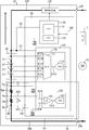
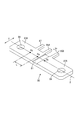
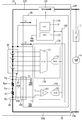
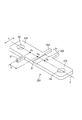
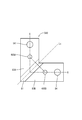
- Block diagram showing the electrical configuration of the battery Perspective view of the resistor Battery perspective Disassembled perspective view of the battery Perspective view of the inner lid Perspective view showing a state in which a resistor is fitted to a connector of a circuit board.
- the figure which shows the current path of the current consumption Block diagram showing the electrical configuration of the battery Perspective view showing another embodiment of the resistor Block diagram showing other embodiments of the battery Block diagram showing other embodiments of the battery
- the current measuring device for measuring the current of the power storage element is a measuring resistor located on the current path and having a resistor, a pair of detection points located on both sides of the resistor on the current path, and a pair of detection points. It has a pair of voltage input units connected to the detection points, and is connected to a common ground between the current detection unit that detects the current of the power storage element from the voltage difference between the pair of detection points and the current detection unit.
- the resistance of the current path from one of the pair of detection points close to the ground connection point to the ground connection point, including the ground connection point, is a permissible value of the input voltage of the current detection unit. , It is smaller than the value divided by the predetermined current of the power storage element.
- the voltage at at least one detection point does not exceed the allowable value of the input voltage of the current detection unit. Since the input voltage is not saturated at at least one detection point, the current measurement error can be suppressed.
- the resistance of the current path from one of the detection points to the ground connection point is a voltage obtained by subtracting the voltage across the resistor at a predetermined current from the allowable value of the input voltage of the current detection unit. It may be smaller than the value divided by.
- the input voltage is not saturated at both of the pair of detection points, so that the current measurement accuracy can be further improved.
- the measuring resistor has a pair of electrodes on both sides of the resistor, the pair of electrodes has a pair of detection points, and one of the pair of electrodes has the electrode of one.
- the ground connection point may be provided.
- the distance from one detection point to the ground connection point is shortened, and the resistance from one detection point to the ground connection point is reduced. Can be done. By reducing the resistance, it is possible to suppress the voltage rise at the detection point and suppress the saturation of the input voltage.
- the ground connection point is common to one of the detection points, and the resistance of the current path between the two common points may be zero. Since the resistance between the two points becomes zero, it is possible to suppress the voltage rise of the detection point with respect to the ground, and it is possible to suppress the saturation of the input voltage.
- the measurement resistor has a pair of detection terminals corresponding to the pair of the detection points and a ground terminal corresponding to the ground connection point, and the pair of the detection terminals and the ground terminal are substrates. It may be fitted to the connector provided in. Since there is a thermal resistance between each terminal and the connector, heat is less likely to be transferred than when the measurement resistor and the board are connected with a harness, and even if the measurement resistor generates heat, it will affect the board. Can be made smaller.
- the predetermined current may be the maximum current. Even if the power storage element has the maximum current, it is possible to suppress the saturation of the input voltage and suppress the current measurement error.
- FIG. 1 is a side view of an automobile.
- the automobile 1 is an engine-driven vehicle, and has an engine 5 as a driving device.
- FIG. 1 shows only the engine 5 and the battery 20, and omits other parts constituting the automobile 1.
- the battery 20 is an example of a power storage device.
- the electrical configuration of the battery 20 will be described with reference to FIG.
- the battery 20 is for starting the engine.
- a cell motor 15 and an IG switch 17 for starting the engine 5 mounted on the automobile 1 are connected to the battery 20.
- a vehicle load such as electrical components and an alternator (not shown) are connected to the battery 20.
- the battery 20 is charged by the alternator.
- the battery 20 discharges to make up for the shortage.
- the battery 20 includes an assembled battery 30, a measuring resistor 80, a current cutoff device 120, a management unit 130, a signal processing circuit 150, and a circuit board 90.
- the assembled battery 30 is composed of a plurality of secondary batteries 31 connected in series.
- the secondary battery 31 is, for example, a lithium ion secondary battery.
- the assembled battery 30, the current cutoff device 120, and the measuring resistor 80 are connected in series via the power lines 55P and 55N.
- the power lines 55P and 55N are current paths X of the assembled battery 30.
- the power line 55P is a power line that connects the external terminal 22P of the positive electrode and the positive electrode of the assembled battery 30.
- the power line 55N is a power line that connects the external terminal 22N of the negative electrode and the negative electrode of the assembled battery 30.
- the current cutoff device 120 is located on the positive electrode side of the assembled battery 30 and is provided on the power line 55P on the positive electrode side.
- the measurement resistor 80 is located on the negative electrode of the assembled battery 30 and is provided on the power line 55N on the negative electrode side. As shown in FIG. 3, the measuring resistor 80 is a rectangular metal conductor that is long in one direction (direction of the current path X).
- the measuring resistor 80 includes a pair of electrodes 83A and 83B and a resistor 81.
- the resistor 81 is an alloy having a small rate of change in electrical resistance (for example, an alloy of copper, manganese, and nickel: manganin).
- the resistor 81 generates a voltage Vr proportional to the current flowing through the measuring resistor 80.
- the pair of electrodes 83A and 83B are metals such as copper, for example.
- the pair of electrodes 83A and 83B are located on both sides of the resistor 81 in the X direction and are joined to the resistor 81 by welding.
- As the welding method electron beam welding, resistance welding and the like can be used.
- the pair of electrodes 83A and 83B have screw holes 84 for attaching the bus bar.
- the electrode 83A is connected to the negative electrode of the assembled battery 30 by a bus bar (not shown), and the electrode 83B is connected to the external terminal 22N of the negative electrode by a bus bar (not shown).
- the pair of electrodes 83A and 83B have a pair of detection points Pa and Pb.
- the pair of detection points Pa and Pb are located on both sides of the resistor 81 on the current path X.
- the pair of electrodes 83A and 83B have a pair of detection terminals 85A and 85B corresponding to the pair of detection points Pa and Pb.
- the pair of detection terminals 85A and 85B project from the side surfaces of the electrodes 83A and 83B in parallel in the Y direction orthogonal to the current path X.
- the detection terminal 85A of the electrode 83A is located at the detection point Pa of the current path X
- the detection terminal 85B of the electrode 83B is located at the detection point Pb of the current path X.
- the pair of detection points Pa and Pb are electrically connected to the two input terminals 161A and 161B of the first signal processing unit 160 via the detection terminals 85A and 85B and the connector 100, respectively.
- the measuring resistor 80 has a ground connection point Pg.
- the ground connection point Pg is on the electrode 83A and is adjacent to the detection point Pa.
- the ground connection point Pg is a far point located outside the detection point Pa when viewed from the resistor 81.
- the ground connection point Pg is located between the detection point Pa and the negative electrode of the assembled battery 30 on the current path X (see FIG. 2).
- the electrode 83A has a ground terminal 87 corresponding to the ground connection point Pg.
- the ground terminal 87 projects from the side surface of the electrode 83A in the Y direction orthogonal to the current path X.
- the ground terminal 87 is parallel to the detection terminals 85A and 85B.
- the ground terminal 87 of the electrode 83A is located at the ground connection point Pg of the current path X.
- the ground connection point Pg is electrically connected to the common ground GND of the circuit board 90 via the ground terminal 87 and the connector 100.
- the current cutoff device 120 is a semiconductor switch such as a relay or FET. By opening the current cutoff device 120, the current of the battery 20 can be cut off.
- the current cutoff device 120 is normally controlled by CLOSE.
- the signal processing circuit 150 is mounted on the circuit board 90 and includes a first signal processing unit 160 and a second signal processing unit 170.
- the signal processing circuit 150 is connected to the power line 55P on the positive electrode side via the branch line 57, and receives power from the assembled battery 30 as a power source.
- the signal processing circuit 150 is electrically connected to the common ground GND of the circuit board 90.
- the first signal processing unit 160 includes an amplifier 161 and an AD converter 163.
- the amplifier 161 includes two input terminals 161A and 161B and one output terminal 161C.
- the two input terminals 161A and 161B are electrically connected to the two detection points Pa and Pb located on both sides of the resistor 81 via the connector 100 and the detection terminals 85A and 85B, respectively.
- the amplifier 161 amplifies the voltage difference between the two input terminals 161A and 161B, that is, the voltage Vr across the resistor 81.
- the amplifier 161 is a detection unit that detects the voltage Vr across the resistor 81.
- the AD converter 163 is connected to the output terminal 161C of the amplifier 161 and converts the output value of the amplifier 161 from an analog signal to a digital signal for output.
- the first signal processing unit 160 is an example of a current detecting unit that detects the current I of the battery 20 from the voltage difference Vr of the two input terminals 161A and 161B.
- the measuring resistor 80, the connector 100, and the first signal processing unit 160 are examples of the current measuring device 50.
- the second signal processing unit 170 includes a multiplexer 171 and an AD converter 173.
- the multiplexer 171 includes five input terminals 171A to 171E and one output terminal 171F.
- the five input terminals 171A to 171E are electrically connected to the electrodes of each secondary battery 31.
- the multiplexer 171 detects and outputs the voltage of each secondary battery 31 in order while switching the secondary battery 31 to be measured.
- the AD converter 173 is connected to the output terminal 171F of the multiplexer 171 and converts the output value of the multiplexer 171 from an analog signal to a digital signal for output.
- the first signal processing unit 160 and the second signal processing unit 170 are connected to the management unit 130 via the bus 180, and the outputs (measured values) of both signal processing units 160 and 170 are transmitted to the management unit 130. Entered.
- the management unit 130 is mounted on the circuit board 90.
- the management unit 130 includes a CPU 131 and a memory 133.
- the management unit 130 is connected to the power line 55P on the positive electrode side via the branch line 58, and receives power from the assembled battery 30 as a power source.
- the management unit 130 is connected to the common ground GND of the circuit board 90.
- the CPU 131 monitors the current I of the battery 20 based on the output of the first signal processing unit 160.
- the CPU 131 monitors the voltage of each secondary battery 31 and the total voltage of the assembled battery 30 based on the output of the second signal processing unit 170.
- the CPU 131 protects the battery 20 by sending a command to the current cutoff device 120 to cut off the current I.
- SOC state of charge
- SOC is the charged state of the battery 20.
- SOC is the ratio of the remaining capacity to the fully charged capacity (actual capacity) and can be defined by the following equation (1).
- the CPU 131 estimates the SOC of the battery 20 based on the integrated value of the current I measured by the measuring resistor 80 with respect to the time.
- SOC SOCo + 100 ⁇ ( ⁇ Idt) / Co (2) SOC is the initial value of SOC, and I is the current.
- FIG. 4 is a perspective view of the battery
- FIG. 5 is an exploded perspective view of the battery.
- the battery 20 has a block-shaped battery case 21.
- the battery case 21 houses an assembled battery 30 composed of a plurality of secondary batteries 31, a measuring resistor 80, a current cutoff device 120, a circuit board 90, and the like.
- the battery case 21 includes a box-shaped case body 23 that opens upward, a positioning member 24 that positions a plurality of secondary batteries 31, and an inner lid 25 that is mounted on the upper part of the case body 23. And an upper lid 29 attached to the upper part of the inner lid 25.
- a plurality of cell chambers 23A are provided side by side in the X direction in the case main body 23. Each secondary battery 31 is individually housed in each cell chamber 23A.
- the positioning member 24 positions each secondary battery 31 housed in each cell chamber 23A. As shown in FIG. 5, a plurality of bus bars 24A are arranged on the upper surface of the positioning member 24. The plurality of bus bars 24 connect the secondary batteries 31 housed in the cell chambers 23A in series.
- the inner lid 25 has a substantially rectangular shape in a plan view as shown in FIG.
- the inner lid 25 has a pair of external terminals 22P and 22N at both ends in the X direction.
- the pair of external terminals 22P and 22N are made of a metal such as a lead alloy, 22P is an external terminal of a positive electrode, and 22N is an external terminal of a negative electrode.
- the external terminals 22P and 22N are terminals for connecting the battery 20 to an electric load such as a starter motor 15.
- a first accommodating portion 25A and a second accommodating portion 25B are provided on the upper surface of the inner lid 25. These two housing portions 25A and 25B are surrounded by an outer wall 26.
- the circuit board 90 is accommodated in the first accommodating portion 25A in a state of being fixed by screwing. In FIG. 6, the circuit board 90 shows only a part such as the connector 100 and the signal processing circuit 150, and other parts are omitted.
- the circuit board 90 has a substantially rectangular shape, and the connector 100 is arranged on the upper surface of the board.
- the connector 100 is arranged on the opposite portion facing the measuring resistor 80.
- the connector 100 is fixed to the upper surface of the circuit board 90 by a fixing portion 115 such as a claw.
- Connector 100 has three internal terminals (figure omitted). That is, the two internal terminals correspond to the two detection terminals 85A and 85B provided on the measuring resistor 80, and one internal terminal corresponds to the ground terminal 87. Each internal terminal is joined to a conductor pattern provided on the upper surface of the circuit board 90, for example, by soldering.
- the measuring resistor 80 is accommodated in the second accommodating portion 25B.
- the two electrodes 83A and 83B are housed in a screwed state while the two detection terminals 85A and 85B and the ground terminal 87 are fitted to the connector 100 (see FIG. 7). ..
- the detection terminals 85A and 85B When the detection terminals 85A and 85B are fitted to the connector 100, the detection terminals 85A and 85B elastically contact the internal terminals, and the detection terminals 85A and 85B are electrically connected to the first signal processing unit 160 mounted on the circuit board 90. Can be connected.
- the ground terminal 87 When the ground terminal 87 is fitted to the connector 100, the ground terminal 87 elastically contacts the internal terminal, and the ground terminal 87 of the measurement resistor 80 can be electrically connected to the common ground GND of the circuit board 90. ..
- the amplifier 161 has a limitation on the magnitude of the input voltage. When a voltage exceeding the permissible value Vm is input to the amplifier 161, the amplifier 161 is saturated and a measurement error occurs in the measured value of the first signal processing unit 160.
- the permissible value Vm of the input voltage is ⁇ 300 mV as an example. + Is discharge and-is charge.
- the input voltage to the amplifier 161 is saturated to +300 [mV] for both the two detection points Pa and Pb. Measurement error occurs. That is, the potential difference between the two detection points Pa and Pb is correctly measured as +20 [mV], but is measured as zero.
- the ground connection point Pg of the measurement resistor 80 is connected to the common ground GND of the circuit board 90 and has the same potential as the common ground GND of the circuit board 90.
- the ground connection point Pg By setting the ground connection point Pg to the same potential as the common ground GND, the reference potential difference between the measurement resistor 80 and the circuit board 90 can be reduced, and the voltages of the detection points Pa and Pb based on the common ground GND can be reduced. Can be lowered.
- the ground terminal 87 When the ground terminal 87 is provided separately from the detection terminals 85A and 85B, as shown in FIG. 8, the current consumption Ir of the management unit 130 and the signal processing circuit 150 returns to the assembled battery 30 through the ground terminal 87. To do. Therefore, the current consumption Ir does not flow to the detection terminals 85A and 85B, and the deterioration of the current measurement accuracy can be suppressed.
- the electrode 83A When the ground connection point Pg and the detection point Pa are separately provided for the electrode 83A, when a current flows through the measurement resistor 80, a voltage is generated between the ground connection point Pg and the detection point Pa.
- the reason why the voltage is generated is that the electrodes 83A and 83B are made of copper, and the material itself has electric resistance. That is, a voltage is generated between the two points Pg to Pa due to the resistance from the ground connection point Pg to the detection point Pa.
- the resistance Rga of the current path X from the ground connection point Pg to the detection point Pa satisfies the following equation (4), and the permissible value Vm of the input voltage of the first signal processing unit 160 is divided by the maximum current Imax of the battery 20. It is less than the numerical value.
- Vm is the permissible value of the input voltage of the first signal processing unit (amplifier), and Imax is the maximum current of the battery 20.
- the maximum current Imax is the maximum value of the current that the battery 20 can discharge or charge in a short time.
- the maximum current Imax is a numerical value determined by the characteristics (electromotive force, internal resistance, etc.) of the battery 20, and a design value or an experimental value can be used.
- the resistance Rga is proportional to the length L along the current path X from the ground connection point Pg to the detection point Pa, and is inversely proportional to the cross-sectional area S of the electrode 83A. Therefore, the measuring resistor 80 determines the length L along the current path X from the ground terminal 87 to the detection terminal 85A and the cross-sectional area S of the electrode 83A so that the resistance Rga satisfies the equation (4). There is.
- the voltage of the detection terminal 85A does not exceed the allowable value Vm of the input voltage of the first signal processing unit 160 even if the battery 20 has the maximum current Imax. .. Therefore, of the two detection points Pa and Pb, the input voltage is not saturated at one of the detection points Pa that is close to the ground connection point Pg. If the input voltage is not saturated at both the detection point Pa and the detection point Pb, there is almost no current measurement error due to saturation, and the current measurement accuracy can be improved. Further, even when the input voltage is saturated at the detection point Pb, the voltage difference between the two detection points Pa and Pb does not become zero because the detection point Pa is not saturated. Therefore, both the two detection points Pa and Pb can suppress the current measurement error due to saturation as compared with the case where the input voltage is saturated.
- the battery 20 can suppress the measurement error of the current I due to the excess of the input voltage to the first signal processing unit 160, and can improve the measurement accuracy of the current I. Further, by improving the measurement accuracy of the current I, the estimation accuracy of the SOC is also improved.
- the value of the resistance Rga of the current path X from the ground connection point Pg to the detection point Pa is different from that of the first embodiment.
- the resistor Rga satisfies the following equation (5), and is obtained by subtracting the maximum value Vrmax of the voltage Vr across the resistor 81 from the allowable value Vm of the input voltage of the first signal processing unit 160, and the maximum current Imax of the battery 20. It is less than or equal to the value divided by.
- Vm is the permissible value of the input voltage of the first signal processing unit
- Vrmax is the maximum voltage of the resistor 81
- Imax is the maximum current of the battery 20.
- Vrmax is the product of the resistance value of the resistor 81 and the maximum current Imax of the battery 20.
- the voltage of the detection terminal 85B is also the input voltage of the first signal processing unit 160 in addition to the detection terminal 85A. Does not exceed the allowable value Vm. Since the input voltage is not saturated at both of the two detection points Pa and Pb, the current measurement accuracy can be improved.
- the power storage element is the secondary battery 31.
- the secondary battery 31 is not limited to the lithium ion secondary battery, and may be another non-aqueous electrolyte secondary battery. Lead-acid batteries and the like can also be used.
- the power storage element is not limited to the secondary battery 31, but may be a capacitor.
- the power storage element is not limited to the case where a plurality of power storage elements are connected in series and parallel, and may be connected in series or in a single cell configuration.
- the battery 20 is used for the vehicle.
- the usage of the battery 20 is not limited to a specific usage.
- the battery 20 can be used for various purposes such as for moving objects (for vehicles, ships, AGV, etc.) and for stationary use (uninterruptible power supply system, power storage device for photovoltaic power generation system, etc.).
- the first signal processing unit 160 is composed of an amplifier 161 and an AD converter 163.
- the first signal processing unit 160 may have any configuration as long as it has two voltage input terminals and detects the current of the battery 20 from the voltage difference between the two voltage input terminals.
- it may be an amplifier and a comparator.
- a comparator may be used to detect the magnitude of the current from the output value of the amplifier.
- the resistance Rga is defined by the maximum current Imax of the battery 20.
- the resistance Rga may be defined by the rated current of the battery 20. That is, the allowable value Vm of the input voltage of the first signal processing unit 160 may be smaller than the value obtained by dividing the allowable value Vm of the battery 20 by the rated current of the battery 20 (the current of the usage limit at which the battery 20 can be safely used).
- the resistance Rga can be defined by a predetermined current of the battery 20.
- the predetermined current is the maximum current or rated current of the battery. The same applies to the equation (5) of the second embodiment.
- the management unit 130 is provided inside the battery 20.
- the battery 20 may have at least an assembled battery 30 and a signal processing circuit 150, and the management unit 130 may be provided outside the battery 20.
- the ground connection point Pg of the measuring resistor 80 is connected to the common ground GND via the ground terminal 87.
- the ground connection point Pg of the measuring resistor 80 may be connected to the common ground GND using a harness. In this case, it is preferable to provide the measuring resistor 80 with a screw hole for fixing the harness terminal with respect to the ground connection point Pg.
- the measurement resistor 80 is provided with a ground connection point Pg.
- the ground connection point may be anywhere as long as it is on the current path X of the assembled battery 30. It may be in a place other than the measuring resistor 80.
- the ground connection point Pg is provided between the negative electrode of the assembled battery 30 and the resistor 81.
- the ground connection point Pg may be provided between the resistor 81 and the external terminal 22N of the negative electrode.
- the battery 200 shown in FIG. 9 includes a current measuring device 250.
- the current measuring device 250 includes a measuring resistor 280, a connector 100, and a first signal processing unit 160.
- the measurement resistor 280 is provided with a ground connection point Pg between the resistor 81 and the external terminal 22N of the negative electrode.
- the resistance Rgb of the current path X from the ground connection point Pg to the detection point Pb satisfies the equation (4) of the first embodiment or the equation (5) of the second embodiment.
- the measurement resistor 80 is provided with a ground terminal 87 along with the detection terminals 85A and 85B.
- the ground terminal 87 may be provided anywhere in the measuring resistor 80.
- the measurement resistor 380 shown in FIG. 10 has a different ground terminal 87 from the measurement resistor 80 shown in FIG. 3, and the detection terminal 85A of the two long sides of the measurement resistor 380 , 85B is provided, and the ground terminal 87 is provided on the long side opposite to the long side.
- the ground terminal 87 may be provided on the short side of the measuring resistor 380.
- the measurement resistor 80 is arranged on the negative electrode side of the assembled battery 30, but may be arranged on the positive electrode side as long as it is on the current path of the assembled battery 30.
- FIG. 11 is a circuit diagram of the battery 400A.
- the battery 400A has a different way of grounding the measurement resistor 480 from the battery 20. Specifically, the measuring resistor 480 shares the ground connection point Pg with one of the detection points Pa.
- the common two points Pg and Pa are at the same potential, and the resistance of the current path X between the two points Pg and Pa is zero. Therefore, it is possible to suppress the voltage rise of the detection points Pa and Pb with reference to the common ground GND, and it is possible to suppress the saturation of the input voltage of the amplifier 161.
- FIG. 12 is a circuit diagram of the battery 400B.
- the battery 400B has the same ground connection point Pg as the detection point Pa, but the ground line 410G of the measurement resistor 480 is provided separately from the input line 410A to the amplifier 161. It is different.
- the current consumption Ir of the management unit 130 and the signal processing circuit 150 returns to the assembled battery 30 through the ground line 410G and does not pass through the input line 410A. Therefore, since there is no current measurement error due to the current consumption Ir, there is an advantage that the current measurement accuracy is high.
- the two lines 410G and 410A may be commonly connected to the connection hole 485A provided at the detection point Pa as shown in FIG.
- a common connection may be made with a fastener such as a screw 486.
- 411A is a terminal of the input line 410A
- 411G is a terminal of the ground line 410G.
- FIG. 14 is a plan view of the measuring resistor 480.
- the measurement resistor 480 has a connection hole 485A at the detection point Pa and a connection hole 485B at the detection point Pb.
- the two connection holes 485A and 485B are for connecting the input lines 410A and 410B to the amplifier 161.
- the two connection holes 485A and 485B may be symmetrical with respect to the center line Lc of the resistor 81.
- the ground line 410G may be commonly connected to the connection hole 485A, or a dedicated connection hole 485G may be provided exclusively and connected separately from the input line 410A. Further, although the measurement resistor 480 has screw holes 84 at both ends, it may be shared with the connection holes 485A and 485B and abolished.
- FIG. 15 is a plan view of the measuring resistor 580.
- the measuring resistor 580 is different from the measuring resistor 480 in that the outer shape is L-shaped and the current path X is not a straight line.
- the two connection holes 485A and the connection holes 485B can be arranged symmetrically with respect to the center line Lc by inclining the center line Lc of the resistor 81 with respect to the current path X. The same applies to the screw hole 84 for attaching the bus bar.
Landscapes
- Physics & Mathematics (AREA)
- General Physics & Mathematics (AREA)
- Measuring Instrument Details And Bridges, And Automatic Balancing Devices (AREA)
- Secondary Cells (AREA)
- Measurement Of Current Or Voltage (AREA)
Priority Applications (7)
| Application Number | Priority Date | Filing Date | Title |
|---|---|---|---|
| DE112019007982.4T DE112019007982T5 (de) | 2019-12-20 | 2019-12-20 | Strommesseinrichtung und Energiespeichervorrichtung |
| US17/757,374 US12130332B2 (en) | 2019-12-20 | 2019-12-20 | Current measuring device and energy storage apparatus |
| JP2021565287A JP7400831B2 (ja) | 2019-12-20 | 2019-12-20 | 電流計測装置、蓄電装置 |
| CN201980103481.XA CN115023618A (zh) | 2019-12-20 | 2019-12-20 | 电流测量装置、蓄电装置 |
| PCT/JP2019/050109 WO2021124551A1 (ja) | 2019-12-20 | 2019-12-20 | 電流計測装置、蓄電装置 |
| JP2023205355A JP7616551B2 (ja) | 2019-12-20 | 2023-12-05 | 電流計測装置、蓄電装置 |
| JP2024223832A JP7765756B2 (ja) | 2019-12-20 | 2024-12-19 | 電流計測装置、蓄電装置 |
Applications Claiming Priority (1)
| Application Number | Priority Date | Filing Date | Title |
|---|---|---|---|
| PCT/JP2019/050109 WO2021124551A1 (ja) | 2019-12-20 | 2019-12-20 | 電流計測装置、蓄電装置 |
Publications (1)
| Publication Number | Publication Date |
|---|---|
| WO2021124551A1 true WO2021124551A1 (ja) | 2021-06-24 |
Family
ID=76478690
Family Applications (1)
| Application Number | Title | Priority Date | Filing Date |
|---|---|---|---|
| PCT/JP2019/050109 Ceased WO2021124551A1 (ja) | 2019-12-20 | 2019-12-20 | 電流計測装置、蓄電装置 |
Country Status (5)
| Country | Link |
|---|---|
| US (1) | US12130332B2 (https=) |
| JP (3) | JP7400831B2 (https=) |
| CN (1) | CN115023618A (https=) |
| DE (1) | DE112019007982T5 (https=) |
| WO (1) | WO2021124551A1 (https=) |
Cited By (1)
| Publication number | Priority date | Publication date | Assignee | Title |
|---|---|---|---|---|
| JP2024533207A (ja) * | 2021-08-30 | 2024-09-12 | ジアンスウ ポリライブ メディテック カンパニー リミテッド | 電流ピーク検出装置、高電圧発生器及び血管石灰化治療設備 |
Families Citing this family (1)
| Publication number | Priority date | Publication date | Assignee | Title |
|---|---|---|---|---|
| EP4431950B1 (en) * | 2023-03-14 | 2026-04-22 | Munich Electrification GmbH | Current sensor assembly, and method for determining a temperature of a resistor arrangement |
Citations (8)
| Publication number | Priority date | Publication date | Assignee | Title |
|---|---|---|---|---|
| JP2001118607A (ja) * | 1999-10-21 | 2001-04-27 | Hitachi Ltd | 電池パック |
| JP2002257909A (ja) * | 2001-02-28 | 2002-09-11 | Fuji Electric Co Ltd | 充電電流検出回路 |
| JP2007132806A (ja) * | 2005-11-10 | 2007-05-31 | Hioki Ee Corp | インピーダンス測定装置 |
| JP2009282050A (ja) * | 2009-09-03 | 2009-12-03 | Nec Access Technica Ltd | 電流検出装置 |
| JP2011012964A (ja) * | 2009-06-30 | 2011-01-20 | Hitachi Automotive Systems Ltd | 電流検出装置およびこれを用いた制御システム |
| JP2013152231A (ja) * | 2009-02-27 | 2013-08-08 | Hitachi Ltd | 電池監視装置 |
| JP2014509747A (ja) * | 2011-03-29 | 2014-04-21 | コンティネンタル・テーベス・アクチエンゲゼルシヤフト・ウント・コンパニー・オッフェネ・ハンデルスゲゼルシヤフト | 電流センサ |
| JP2016118437A (ja) * | 2014-12-19 | 2016-06-30 | 株式会社デンソー | 電圧検出回路 |
Family Cites Families (13)
| Publication number | Priority date | Publication date | Assignee | Title |
|---|---|---|---|---|
| US8565490B2 (en) * | 2004-07-01 | 2013-10-22 | David A. Krien | Computerized imaging of sporting trophies and method of providing a replica |
| FR2938657B1 (fr) * | 2008-11-17 | 2010-12-31 | Vehicules Electr Soc D | Procede de surveillance de la tension d'un element generateur d'energie electrique d'une batterie |
| JP5221468B2 (ja) | 2009-02-27 | 2013-06-26 | 株式会社日立製作所 | 電池監視装置 |
| JP5489798B2 (ja) | 2010-03-17 | 2014-05-14 | 三菱電機株式会社 | 電流検出装置およびモータシステム |
| JP5845057B2 (ja) | 2011-10-31 | 2016-01-20 | 株式会社デンソー | 電流検出装置 |
| WO2013121872A1 (ja) | 2012-02-14 | 2013-08-22 | コーア株式会社 | 抵抗器の端子接続構造 |
| GB2508836A (en) * | 2012-12-12 | 2014-06-18 | Sony Corp | Shunt resistor current sense circuit for use in a battery state of charge meter |
| JP2015021815A (ja) | 2013-07-18 | 2015-02-02 | 矢崎総業株式会社 | シャント抵抗式電流センサ |
| JP6493353B2 (ja) * | 2016-10-13 | 2019-04-03 | トヨタ自動車株式会社 | 電力供給システム |
| JP7098289B2 (ja) | 2017-08-29 | 2022-07-11 | Koa株式会社 | 電流測定装置 |
| US20200028219A1 (en) * | 2018-07-19 | 2020-01-23 | Navitas Solutions, Inc. | Fault-tolerant electronic battery sensing |
| CN113453942B (zh) * | 2019-02-19 | 2024-08-23 | 三洋电机株式会社 | 漏电检测装置、车辆用电源系统 |
| JP7289782B2 (ja) | 2019-12-19 | 2023-06-12 | 株式会社東芝 | 電流検出装置 |
-
2019
- 2019-12-20 WO PCT/JP2019/050109 patent/WO2021124551A1/ja not_active Ceased
- 2019-12-20 JP JP2021565287A patent/JP7400831B2/ja active Active
- 2019-12-20 CN CN201980103481.XA patent/CN115023618A/zh active Pending
- 2019-12-20 US US17/757,374 patent/US12130332B2/en active Active
- 2019-12-20 DE DE112019007982.4T patent/DE112019007982T5/de active Pending
-
2023
- 2023-12-05 JP JP2023205355A patent/JP7616551B2/ja active Active
-
2024
- 2024-12-19 JP JP2024223832A patent/JP7765756B2/ja active Active
Patent Citations (8)
| Publication number | Priority date | Publication date | Assignee | Title |
|---|---|---|---|---|
| JP2001118607A (ja) * | 1999-10-21 | 2001-04-27 | Hitachi Ltd | 電池パック |
| JP2002257909A (ja) * | 2001-02-28 | 2002-09-11 | Fuji Electric Co Ltd | 充電電流検出回路 |
| JP2007132806A (ja) * | 2005-11-10 | 2007-05-31 | Hioki Ee Corp | インピーダンス測定装置 |
| JP2013152231A (ja) * | 2009-02-27 | 2013-08-08 | Hitachi Ltd | 電池監視装置 |
| JP2011012964A (ja) * | 2009-06-30 | 2011-01-20 | Hitachi Automotive Systems Ltd | 電流検出装置およびこれを用いた制御システム |
| JP2009282050A (ja) * | 2009-09-03 | 2009-12-03 | Nec Access Technica Ltd | 電流検出装置 |
| JP2014509747A (ja) * | 2011-03-29 | 2014-04-21 | コンティネンタル・テーベス・アクチエンゲゼルシヤフト・ウント・コンパニー・オッフェネ・ハンデルスゲゼルシヤフト | 電流センサ |
| JP2016118437A (ja) * | 2014-12-19 | 2016-06-30 | 株式会社デンソー | 電圧検出回路 |
Cited By (2)
| Publication number | Priority date | Publication date | Assignee | Title |
|---|---|---|---|---|
| JP2024533207A (ja) * | 2021-08-30 | 2024-09-12 | ジアンスウ ポリライブ メディテック カンパニー リミテッド | 電流ピーク検出装置、高電圧発生器及び血管石灰化治療設備 |
| JP7619706B2 (ja) | 2021-08-30 | 2025-01-22 | ジアンスウ ポリライブ メディテック カンパニー リミテッド | 電流ピーク検出装置、高電圧発生器及び血管石灰化治療設備 |
Also Published As
| Publication number | Publication date |
|---|---|
| CN115023618A (zh) | 2022-09-06 |
| JP2024019296A (ja) | 2024-02-08 |
| DE112019007982T5 (de) | 2022-10-13 |
| JPWO2021124551A1 (https=) | 2021-06-24 |
| JP2025031801A (ja) | 2025-03-07 |
| US12130332B2 (en) | 2024-10-29 |
| JP7400831B2 (ja) | 2023-12-19 |
| JP7616551B2 (ja) | 2025-01-17 |
| JP7765756B2 (ja) | 2025-11-07 |
| US20230009467A1 (en) | 2023-01-12 |
Similar Documents
| Publication | Publication Date | Title |
|---|---|---|
| US11313885B2 (en) | Integrated current-measuring apparatus | |
| JP7765756B2 (ja) | 電流計測装置、蓄電装置 | |
| EP2259365B1 (en) | Device for detecting abnormality in a secondary battery | |
| US11493013B2 (en) | Current detector, management device, battery for starting engine | |
| EP2541641A1 (en) | Battery module, battery system, electric vehicle, mobile body, power storage device, power supply device, and electric apparatus | |
| KR20020044170A (ko) | 배터리 충전상태를 모니터하기 위한 분로저항장치 | |
| CN101872880A (zh) | 电池模块、电池系统及电动车辆 | |
| CN115004043A (zh) | 电池测定装置 | |
| WO2021014872A1 (ja) | 電流計測装置、電流の計測方法、蓄電装置及び抵抗器 | |
| EP3316348A1 (en) | Busbar for a battery system and battery system | |
| US11639967B2 (en) | Sensor system for a battery module | |
| CN103887574B (zh) | 电池状态监视装置以及具备该电池状态监视装置的电池模块 | |
| US20240410955A1 (en) | Battery pack | |
| WO2019150931A1 (ja) | 管理装置、蓄電装置 | |
| JP2020201153A (ja) | 制御基板、蓄電装置 | |
| JP7539019B2 (ja) | 蓄電素子の管理装置、蓄電装置、及び、車両 | |
| KR102512061B1 (ko) | 배터리 모듈을 위한 센서 시스템 | |
| WO2020246285A1 (ja) | 監視ユニット、蓄電装置、監視ユニットの起動方法 |
Legal Events
| Date | Code | Title | Description |
|---|---|---|---|
| 121 | Ep: the epo has been informed by wipo that ep was designated in this application |
Ref document number: 19956575 Country of ref document: EP Kind code of ref document: A1 |
|
| ENP | Entry into the national phase |
Ref document number: 2021565287 Country of ref document: JP Kind code of ref document: A |
|
| 122 | Ep: pct application non-entry in european phase |
Ref document number: 19956575 Country of ref document: EP Kind code of ref document: A1 |