WO2021112077A1 - Layered composite - Google Patents
Layered composite Download PDFInfo
- Publication number
- WO2021112077A1 WO2021112077A1 PCT/JP2020/044663 JP2020044663W WO2021112077A1 WO 2021112077 A1 WO2021112077 A1 WO 2021112077A1 JP 2020044663 W JP2020044663 W JP 2020044663W WO 2021112077 A1 WO2021112077 A1 WO 2021112077A1
- Authority
- WO
- WIPO (PCT)
- Prior art keywords
- laminated
- laminated composite
- carbon fiber
- fiber reinforced
- reinforced resin
- Prior art date
Links
- 239000002131 composite material Substances 0.000 title claims abstract description 85
- 229910000831 Steel Inorganic materials 0.000 claims abstract description 98
- 239000010959 steel Substances 0.000 claims abstract description 98
- 229920000049 Carbon (fiber) Polymers 0.000 claims abstract description 88
- 239000004917 carbon fiber Substances 0.000 claims abstract description 88
- 229920005989 resin Polymers 0.000 claims abstract description 87
- 239000011347 resin Substances 0.000 claims abstract description 87
- VNWKTOKETHGBQD-UHFFFAOYSA-N methane Chemical compound C VNWKTOKETHGBQD-UHFFFAOYSA-N 0.000 claims abstract description 75
- 238000000465 moulding Methods 0.000 claims description 16
- 238000007747 plating Methods 0.000 claims description 14
- 230000037303 wrinkles Effects 0.000 claims description 8
- 238000011156 evaluation Methods 0.000 claims description 6
- 238000004381 surface treatment Methods 0.000 claims description 4
- 229910052759 nickel Inorganic materials 0.000 claims description 3
- 229910052725 zinc Inorganic materials 0.000 claims description 3
- 238000004519 manufacturing process Methods 0.000 description 27
- 239000000835 fiber Substances 0.000 description 19
- 238000000034 method Methods 0.000 description 17
- 238000000137 annealing Methods 0.000 description 9
- 238000012545 processing Methods 0.000 description 8
- 238000011282 treatment Methods 0.000 description 8
- 230000000052 comparative effect Effects 0.000 description 7
- 239000000126 substance Substances 0.000 description 7
- 229920005992 thermoplastic resin Polymers 0.000 description 7
- 238000006243 chemical reaction Methods 0.000 description 6
- 238000005259 measurement Methods 0.000 description 6
- 229910052751 metal Inorganic materials 0.000 description 6
- 239000002184 metal Substances 0.000 description 6
- 238000010438 heat treatment Methods 0.000 description 5
- 239000000463 material Substances 0.000 description 5
- NBIIXXVUZAFLBC-UHFFFAOYSA-N Phosphoric acid Chemical compound OP(O)(O)=O NBIIXXVUZAFLBC-UHFFFAOYSA-N 0.000 description 4
- 239000011248 coating agent Substances 0.000 description 4
- 238000000576 coating method Methods 0.000 description 4
- 239000012783 reinforcing fiber Substances 0.000 description 4
- 229920001169 thermoplastic Polymers 0.000 description 4
- 239000004416 thermosoftening plastic Substances 0.000 description 4
- 229910052782 aluminium Inorganic materials 0.000 description 3
- XAGFODPZIPBFFR-UHFFFAOYSA-N aluminium Chemical compound [Al] XAGFODPZIPBFFR-UHFFFAOYSA-N 0.000 description 3
- 238000005452 bending Methods 0.000 description 3
- 238000001816 cooling Methods 0.000 description 3
- 238000010586 diagram Methods 0.000 description 3
- 239000003822 epoxy resin Substances 0.000 description 3
- 238000010030 laminating Methods 0.000 description 3
- 239000010410 layer Substances 0.000 description 3
- 229920000647 polyepoxide Polymers 0.000 description 3
- 230000003746 surface roughness Effects 0.000 description 3
- 238000012360 testing method Methods 0.000 description 3
- 229910052720 vanadium Inorganic materials 0.000 description 3
- LEONUFNNVUYDNQ-UHFFFAOYSA-N vanadium atom Chemical compound [V] LEONUFNNVUYDNQ-UHFFFAOYSA-N 0.000 description 3
- 239000013585 weight reducing agent Substances 0.000 description 3
- 239000004925 Acrylic resin Substances 0.000 description 2
- 229920000178 Acrylic resin Polymers 0.000 description 2
- QAOWNCQODCNURD-UHFFFAOYSA-N Sulfuric acid Chemical compound OS(O)(=O)=O QAOWNCQODCNURD-UHFFFAOYSA-N 0.000 description 2
- 239000002313 adhesive film Substances 0.000 description 2
- 229910000147 aluminium phosphate Inorganic materials 0.000 description 2
- 230000008901 benefit Effects 0.000 description 2
- IISBACLAFKSPIT-UHFFFAOYSA-N bisphenol A Chemical compound C=1C=C(O)C=CC=1C(C)(C)C1=CC=C(O)C=C1 IISBACLAFKSPIT-UHFFFAOYSA-N 0.000 description 2
- 239000010960 cold rolled steel Substances 0.000 description 2
- 230000005484 gravity Effects 0.000 description 2
- 239000011159 matrix material Substances 0.000 description 2
- 239000007769 metal material Substances 0.000 description 2
- 230000000704 physical effect Effects 0.000 description 2
- -1 polyethylene Polymers 0.000 description 2
- 238000002360 preparation method Methods 0.000 description 2
- 239000011342 resin composition Substances 0.000 description 2
- 238000005096 rolling process Methods 0.000 description 2
- 238000007788 roughening Methods 0.000 description 2
- 238000003892 spreading Methods 0.000 description 2
- 229920002803 thermoplastic polyurethane Polymers 0.000 description 2
- OKTJSMMVPCPJKN-UHFFFAOYSA-N Carbon Chemical compound [C] OKTJSMMVPCPJKN-UHFFFAOYSA-N 0.000 description 1
- 229910001208 Crucible steel Inorganic materials 0.000 description 1
- 239000004593 Epoxy Substances 0.000 description 1
- 229910000990 Ni alloy Inorganic materials 0.000 description 1
- 239000004698 Polyethylene Substances 0.000 description 1
- 239000004743 Polypropylene Substances 0.000 description 1
- 229910001297 Zn alloy Inorganic materials 0.000 description 1
- 239000002253 acid Substances 0.000 description 1
- NIXOWILDQLNWCW-UHFFFAOYSA-N acrylic acid group Chemical group C(C=C)(=O)O NIXOWILDQLNWCW-UHFFFAOYSA-N 0.000 description 1
- 239000000853 adhesive Substances 0.000 description 1
- 230000001070 adhesive effect Effects 0.000 description 1
- 229910045601 alloy Inorganic materials 0.000 description 1
- 239000000956 alloy Substances 0.000 description 1
- 229920006231 aramid fiber Polymers 0.000 description 1
- 238000011074 autoclave method Methods 0.000 description 1
- 238000005422 blasting Methods 0.000 description 1
- QHIWVLPBUQWDMQ-UHFFFAOYSA-N butyl prop-2-enoate;methyl 2-methylprop-2-enoate;prop-2-enoic acid Chemical compound OC(=O)C=C.COC(=O)C(C)=C.CCCCOC(=O)C=C QHIWVLPBUQWDMQ-UHFFFAOYSA-N 0.000 description 1
- 229910052799 carbon Inorganic materials 0.000 description 1
- 230000008859 change Effects 0.000 description 1
- 238000003486 chemical etching Methods 0.000 description 1
- ZCDOYSPFYFSLEW-UHFFFAOYSA-N chromate(2-) Chemical compound [O-][Cr]([O-])(=O)=O ZCDOYSPFYFSLEW-UHFFFAOYSA-N 0.000 description 1
- 229910052804 chromium Inorganic materials 0.000 description 1
- 238000005097 cold rolling Methods 0.000 description 1
- 238000007796 conventional method Methods 0.000 description 1
- 238000005260 corrosion Methods 0.000 description 1
- 230000007797 corrosion Effects 0.000 description 1
- 238000005238 degreasing Methods 0.000 description 1
- 238000011161 development Methods 0.000 description 1
- 230000000694 effects Effects 0.000 description 1
- 238000002474 experimental method Methods 0.000 description 1
- 230000002349 favourable effect Effects 0.000 description 1
- 239000003365 glass fiber Substances 0.000 description 1
- 230000017525 heat dissipation Effects 0.000 description 1
- 238000005098 hot rolling Methods 0.000 description 1
- 230000006872 improvement Effects 0.000 description 1
- 230000013011 mating Effects 0.000 description 1
- 238000007721 mold pressing method Methods 0.000 description 1
- 229910052750 molybdenum Inorganic materials 0.000 description 1
- 230000035515 penetration Effects 0.000 description 1
- 230000035699 permeability Effects 0.000 description 1
- 238000005554 pickling Methods 0.000 description 1
- 229920001225 polyester resin Polymers 0.000 description 1
- 239000004645 polyester resin Substances 0.000 description 1
- 229920000573 polyethylene Polymers 0.000 description 1
- 229920001155 polypropylene Polymers 0.000 description 1
- 238000003825 pressing Methods 0.000 description 1
- 230000008569 process Effects 0.000 description 1
- 238000010791 quenching Methods 0.000 description 1
- 230000000171 quenching effect Effects 0.000 description 1
- RMAQACBXLXPBSY-UHFFFAOYSA-N silicic acid Chemical compound O[Si](O)(O)O RMAQACBXLXPBSY-UHFFFAOYSA-N 0.000 description 1
- 235000012239 silicon dioxide Nutrition 0.000 description 1
- 239000002356 single layer Substances 0.000 description 1
- 230000001629 suppression Effects 0.000 description 1
- 229910052718 tin Inorganic materials 0.000 description 1
- 239000002759 woven fabric Substances 0.000 description 1
Images


Classifications
-
- B—PERFORMING OPERATIONS; TRANSPORTING
- B29—WORKING OF PLASTICS; WORKING OF SUBSTANCES IN A PLASTIC STATE IN GENERAL
- B29C—SHAPING OR JOINING OF PLASTICS; SHAPING OF MATERIAL IN A PLASTIC STATE, NOT OTHERWISE PROVIDED FOR; AFTER-TREATMENT OF THE SHAPED PRODUCTS, e.g. REPAIRING
- B29C70/00—Shaping composites, i.e. plastics material comprising reinforcements, fillers or preformed parts, e.g. inserts
- B29C70/04—Shaping composites, i.e. plastics material comprising reinforcements, fillers or preformed parts, e.g. inserts comprising reinforcements only, e.g. self-reinforcing plastics
- B29C70/06—Fibrous reinforcements only
- B29C70/10—Fibrous reinforcements only characterised by the structure of fibrous reinforcements, e.g. hollow fibres
- B29C70/12—Fibrous reinforcements only characterised by the structure of fibrous reinforcements, e.g. hollow fibres using fibres of short length, e.g. in the form of a mat
- B29C70/14—Fibrous reinforcements only characterised by the structure of fibrous reinforcements, e.g. hollow fibres using fibres of short length, e.g. in the form of a mat oriented
-
- B—PERFORMING OPERATIONS; TRANSPORTING
- B29—WORKING OF PLASTICS; WORKING OF SUBSTANCES IN A PLASTIC STATE IN GENERAL
- B29C—SHAPING OR JOINING OF PLASTICS; SHAPING OF MATERIAL IN A PLASTIC STATE, NOT OTHERWISE PROVIDED FOR; AFTER-TREATMENT OF THE SHAPED PRODUCTS, e.g. REPAIRING
- B29C70/00—Shaping composites, i.e. plastics material comprising reinforcements, fillers or preformed parts, e.g. inserts
- B29C70/04—Shaping composites, i.e. plastics material comprising reinforcements, fillers or preformed parts, e.g. inserts comprising reinforcements only, e.g. self-reinforcing plastics
- B29C70/06—Fibrous reinforcements only
- B29C70/10—Fibrous reinforcements only characterised by the structure of fibrous reinforcements, e.g. hollow fibres
- B29C70/12—Fibrous reinforcements only characterised by the structure of fibrous reinforcements, e.g. hollow fibres using fibres of short length, e.g. in the form of a mat
-
- B—PERFORMING OPERATIONS; TRANSPORTING
- B29—WORKING OF PLASTICS; WORKING OF SUBSTANCES IN A PLASTIC STATE IN GENERAL
- B29C—SHAPING OR JOINING OF PLASTICS; SHAPING OF MATERIAL IN A PLASTIC STATE, NOT OTHERWISE PROVIDED FOR; AFTER-TREATMENT OF THE SHAPED PRODUCTS, e.g. REPAIRING
- B29C70/00—Shaping composites, i.e. plastics material comprising reinforcements, fillers or preformed parts, e.g. inserts
- B29C70/04—Shaping composites, i.e. plastics material comprising reinforcements, fillers or preformed parts, e.g. inserts comprising reinforcements only, e.g. self-reinforcing plastics
- B29C70/28—Shaping operations therefor
- B29C70/30—Shaping by lay-up, i.e. applying fibres, tape or broadsheet on a mould, former or core; Shaping by spray-up, i.e. spraying of fibres on a mould, former or core
- B29C70/34—Shaping by lay-up, i.e. applying fibres, tape or broadsheet on a mould, former or core; Shaping by spray-up, i.e. spraying of fibres on a mould, former or core and shaping or impregnating by compression, i.e. combined with compressing after the lay-up operation
-
- B—PERFORMING OPERATIONS; TRANSPORTING
- B29—WORKING OF PLASTICS; WORKING OF SUBSTANCES IN A PLASTIC STATE IN GENERAL
- B29C—SHAPING OR JOINING OF PLASTICS; SHAPING OF MATERIAL IN A PLASTIC STATE, NOT OTHERWISE PROVIDED FOR; AFTER-TREATMENT OF THE SHAPED PRODUCTS, e.g. REPAIRING
- B29C70/00—Shaping composites, i.e. plastics material comprising reinforcements, fillers or preformed parts, e.g. inserts
- B29C70/88—Shaping composites, i.e. plastics material comprising reinforcements, fillers or preformed parts, e.g. inserts characterised primarily by possessing specific properties, e.g. electrically conductive or locally reinforced
- B29C70/882—Shaping composites, i.e. plastics material comprising reinforcements, fillers or preformed parts, e.g. inserts characterised primarily by possessing specific properties, e.g. electrically conductive or locally reinforced partly or totally electrically conductive, e.g. for EMI shielding
- B29C70/885—Shaping composites, i.e. plastics material comprising reinforcements, fillers or preformed parts, e.g. inserts characterised primarily by possessing specific properties, e.g. electrically conductive or locally reinforced partly or totally electrically conductive, e.g. for EMI shielding with incorporated metallic wires, nets, films or plates
-
- B—PERFORMING OPERATIONS; TRANSPORTING
- B32—LAYERED PRODUCTS
- B32B—LAYERED PRODUCTS, i.e. PRODUCTS BUILT-UP OF STRATA OF FLAT OR NON-FLAT, e.g. CELLULAR OR HONEYCOMB, FORM
- B32B15/00—Layered products comprising a layer of metal
- B32B15/04—Layered products comprising a layer of metal comprising metal as the main or only constituent of a layer, which is next to another layer of the same or of a different material
- B32B15/08—Layered products comprising a layer of metal comprising metal as the main or only constituent of a layer, which is next to another layer of the same or of a different material of synthetic resin
-
- B—PERFORMING OPERATIONS; TRANSPORTING
- B32—LAYERED PRODUCTS
- B32B—LAYERED PRODUCTS, i.e. PRODUCTS BUILT-UP OF STRATA OF FLAT OR NON-FLAT, e.g. CELLULAR OR HONEYCOMB, FORM
- B32B15/00—Layered products comprising a layer of metal
- B32B15/14—Layered products comprising a layer of metal next to a fibrous or filamentary layer
-
- B—PERFORMING OPERATIONS; TRANSPORTING
- B32—LAYERED PRODUCTS
- B32B—LAYERED PRODUCTS, i.e. PRODUCTS BUILT-UP OF STRATA OF FLAT OR NON-FLAT, e.g. CELLULAR OR HONEYCOMB, FORM
- B32B15/00—Layered products comprising a layer of metal
- B32B15/18—Layered products comprising a layer of metal comprising iron or steel
-
- B—PERFORMING OPERATIONS; TRANSPORTING
- B32—LAYERED PRODUCTS
- B32B—LAYERED PRODUCTS, i.e. PRODUCTS BUILT-UP OF STRATA OF FLAT OR NON-FLAT, e.g. CELLULAR OR HONEYCOMB, FORM
- B32B25/00—Layered products comprising a layer of natural or synthetic rubber
- B32B25/02—Layered products comprising a layer of natural or synthetic rubber with fibres or particles being present as additives in the layer
-
- B—PERFORMING OPERATIONS; TRANSPORTING
- B32—LAYERED PRODUCTS
- B32B—LAYERED PRODUCTS, i.e. PRODUCTS BUILT-UP OF STRATA OF FLAT OR NON-FLAT, e.g. CELLULAR OR HONEYCOMB, FORM
- B32B3/00—Layered products comprising a layer with external or internal discontinuities or unevennesses, or a layer of non-planar form; Layered products having particular features of form
- B32B3/02—Layered products comprising a layer with external or internal discontinuities or unevennesses, or a layer of non-planar form; Layered products having particular features of form characterised by features of form at particular places, e.g. in edge regions
-
- B—PERFORMING OPERATIONS; TRANSPORTING
- B32—LAYERED PRODUCTS
- B32B—LAYERED PRODUCTS, i.e. PRODUCTS BUILT-UP OF STRATA OF FLAT OR NON-FLAT, e.g. CELLULAR OR HONEYCOMB, FORM
- B32B33/00—Layered products characterised by particular properties or particular surface features, e.g. particular surface coatings; Layered products designed for particular purposes not covered by another single class
-
- B—PERFORMING OPERATIONS; TRANSPORTING
- B32—LAYERED PRODUCTS
- B32B—LAYERED PRODUCTS, i.e. PRODUCTS BUILT-UP OF STRATA OF FLAT OR NON-FLAT, e.g. CELLULAR OR HONEYCOMB, FORM
- B32B37/00—Methods or apparatus for laminating, e.g. by curing or by ultrasonic bonding
- B32B37/14—Methods or apparatus for laminating, e.g. by curing or by ultrasonic bonding characterised by the properties of the layers
- B32B37/16—Methods or apparatus for laminating, e.g. by curing or by ultrasonic bonding characterised by the properties of the layers with all layers existing as coherent layers before laminating
- B32B37/20—Methods or apparatus for laminating, e.g. by curing or by ultrasonic bonding characterised by the properties of the layers with all layers existing as coherent layers before laminating involving the assembly of continuous webs only
-
- B—PERFORMING OPERATIONS; TRANSPORTING
- B32—LAYERED PRODUCTS
- B32B—LAYERED PRODUCTS, i.e. PRODUCTS BUILT-UP OF STRATA OF FLAT OR NON-FLAT, e.g. CELLULAR OR HONEYCOMB, FORM
- B32B5/00—Layered products characterised by the non- homogeneity or physical structure, i.e. comprising a fibrous, filamentary, particulate or foam layer; Layered products characterised by having a layer differing constitutionally or physically in different parts
- B32B5/02—Layered products characterised by the non- homogeneity or physical structure, i.e. comprising a fibrous, filamentary, particulate or foam layer; Layered products characterised by having a layer differing constitutionally or physically in different parts characterised by structural features of a fibrous or filamentary layer
-
- C—CHEMISTRY; METALLURGY
- C08—ORGANIC MACROMOLECULAR COMPOUNDS; THEIR PREPARATION OR CHEMICAL WORKING-UP; COMPOSITIONS BASED THEREON
- C08J—WORKING-UP; GENERAL PROCESSES OF COMPOUNDING; AFTER-TREATMENT NOT COVERED BY SUBCLASSES C08B, C08C, C08F, C08G or C08H
- C08J3/00—Processes of treating or compounding macromolecular substances
- C08J3/12—Powdering or granulating
- C08J3/122—Pulverisation by spraying
-
- C—CHEMISTRY; METALLURGY
- C08—ORGANIC MACROMOLECULAR COMPOUNDS; THEIR PREPARATION OR CHEMICAL WORKING-UP; COMPOSITIONS BASED THEREON
- C08J—WORKING-UP; GENERAL PROCESSES OF COMPOUNDING; AFTER-TREATMENT NOT COVERED BY SUBCLASSES C08B, C08C, C08F, C08G or C08H
- C08J5/00—Manufacture of articles or shaped materials containing macromolecular substances
- C08J5/24—Impregnating materials with prepolymers which can be polymerised in situ, e.g. manufacture of prepregs
- C08J5/241—Impregnating materials with prepolymers which can be polymerised in situ, e.g. manufacture of prepregs using inorganic fibres
- C08J5/243—Impregnating materials with prepolymers which can be polymerised in situ, e.g. manufacture of prepregs using inorganic fibres using carbon fibres
-
- C—CHEMISTRY; METALLURGY
- C08—ORGANIC MACROMOLECULAR COMPOUNDS; THEIR PREPARATION OR CHEMICAL WORKING-UP; COMPOSITIONS BASED THEREON
- C08J—WORKING-UP; GENERAL PROCESSES OF COMPOUNDING; AFTER-TREATMENT NOT COVERED BY SUBCLASSES C08B, C08C, C08F, C08G or C08H
- C08J7/00—Chemical treatment or coating of shaped articles made of macromolecular substances
- C08J7/04—Coating
- C08J7/042—Coating with two or more layers, where at least one layer of a composition contains a polymer binder
-
- C—CHEMISTRY; METALLURGY
- C08—ORGANIC MACROMOLECULAR COMPOUNDS; THEIR PREPARATION OR CHEMICAL WORKING-UP; COMPOSITIONS BASED THEREON
- C08J—WORKING-UP; GENERAL PROCESSES OF COMPOUNDING; AFTER-TREATMENT NOT COVERED BY SUBCLASSES C08B, C08C, C08F, C08G or C08H
- C08J7/00—Chemical treatment or coating of shaped articles made of macromolecular substances
- C08J7/04—Coating
- C08J7/043—Improving the adhesiveness of the coatings per se, e.g. forming primers
-
- C—CHEMISTRY; METALLURGY
- C08—ORGANIC MACROMOLECULAR COMPOUNDS; THEIR PREPARATION OR CHEMICAL WORKING-UP; COMPOSITIONS BASED THEREON
- C08J—WORKING-UP; GENERAL PROCESSES OF COMPOUNDING; AFTER-TREATMENT NOT COVERED BY SUBCLASSES C08B, C08C, C08F, C08G or C08H
- C08J7/00—Chemical treatment or coating of shaped articles made of macromolecular substances
- C08J7/04—Coating
- C08J7/05—Forming flame retardant coatings or fire resistant coatings
-
- B—PERFORMING OPERATIONS; TRANSPORTING
- B29—WORKING OF PLASTICS; WORKING OF SUBSTANCES IN A PLASTIC STATE IN GENERAL
- B29K—INDEXING SCHEME ASSOCIATED WITH SUBCLASSES B29B, B29C OR B29D, RELATING TO MOULDING MATERIALS OR TO MATERIALS FOR MOULDS, REINFORCEMENTS, FILLERS OR PREFORMED PARTS, e.g. INSERTS
- B29K2307/00—Use of elements other than metals as reinforcement
- B29K2307/04—Carbon
-
- B—PERFORMING OPERATIONS; TRANSPORTING
- B29—WORKING OF PLASTICS; WORKING OF SUBSTANCES IN A PLASTIC STATE IN GENERAL
- B29L—INDEXING SCHEME ASSOCIATED WITH SUBCLASS B29C, RELATING TO PARTICULAR ARTICLES
- B29L2031/00—Other particular articles
- B29L2031/001—Profiled members, e.g. beams, sections
-
- B—PERFORMING OPERATIONS; TRANSPORTING
- B32—LAYERED PRODUCTS
- B32B—LAYERED PRODUCTS, i.e. PRODUCTS BUILT-UP OF STRATA OF FLAT OR NON-FLAT, e.g. CELLULAR OR HONEYCOMB, FORM
- B32B2250/00—Layers arrangement
- B32B2250/02—2 layers
-
- B—PERFORMING OPERATIONS; TRANSPORTING
- B32—LAYERED PRODUCTS
- B32B—LAYERED PRODUCTS, i.e. PRODUCTS BUILT-UP OF STRATA OF FLAT OR NON-FLAT, e.g. CELLULAR OR HONEYCOMB, FORM
- B32B2250/00—Layers arrangement
- B32B2250/40—Symmetrical or sandwich layers, e.g. ABA, ABCBA, ABCCBA
-
- B—PERFORMING OPERATIONS; TRANSPORTING
- B32—LAYERED PRODUCTS
- B32B—LAYERED PRODUCTS, i.e. PRODUCTS BUILT-UP OF STRATA OF FLAT OR NON-FLAT, e.g. CELLULAR OR HONEYCOMB, FORM
- B32B2255/00—Coating on the layer surface
- B32B2255/06—Coating on the layer surface on metal layer
-
- B—PERFORMING OPERATIONS; TRANSPORTING
- B32—LAYERED PRODUCTS
- B32B—LAYERED PRODUCTS, i.e. PRODUCTS BUILT-UP OF STRATA OF FLAT OR NON-FLAT, e.g. CELLULAR OR HONEYCOMB, FORM
- B32B2255/00—Coating on the layer surface
- B32B2255/20—Inorganic coating
- B32B2255/205—Metallic coating
-
- B—PERFORMING OPERATIONS; TRANSPORTING
- B32—LAYERED PRODUCTS
- B32B—LAYERED PRODUCTS, i.e. PRODUCTS BUILT-UP OF STRATA OF FLAT OR NON-FLAT, e.g. CELLULAR OR HONEYCOMB, FORM
- B32B2260/00—Layered product comprising an impregnated, embedded, or bonded layer wherein the layer comprises an impregnation, embedding, or binder material
- B32B2260/02—Composition of the impregnated, bonded or embedded layer
- B32B2260/021—Fibrous or filamentary layer
-
- B—PERFORMING OPERATIONS; TRANSPORTING
- B32—LAYERED PRODUCTS
- B32B—LAYERED PRODUCTS, i.e. PRODUCTS BUILT-UP OF STRATA OF FLAT OR NON-FLAT, e.g. CELLULAR OR HONEYCOMB, FORM
- B32B2260/00—Layered product comprising an impregnated, embedded, or bonded layer wherein the layer comprises an impregnation, embedding, or binder material
- B32B2260/04—Impregnation, embedding, or binder material
- B32B2260/046—Synthetic resin
-
- B—PERFORMING OPERATIONS; TRANSPORTING
- B32—LAYERED PRODUCTS
- B32B—LAYERED PRODUCTS, i.e. PRODUCTS BUILT-UP OF STRATA OF FLAT OR NON-FLAT, e.g. CELLULAR OR HONEYCOMB, FORM
- B32B2262/00—Composition or structural features of fibres which form a fibrous or filamentary layer or are present as additives
- B32B2262/10—Inorganic fibres
- B32B2262/106—Carbon fibres, e.g. graphite fibres
-
- B—PERFORMING OPERATIONS; TRANSPORTING
- B32—LAYERED PRODUCTS
- B32B—LAYERED PRODUCTS, i.e. PRODUCTS BUILT-UP OF STRATA OF FLAT OR NON-FLAT, e.g. CELLULAR OR HONEYCOMB, FORM
- B32B2262/00—Composition or structural features of fibres which form a fibrous or filamentary layer or are present as additives
- B32B2262/16—Structural features of fibres, filaments or yarns e.g. wrapped, coiled, crimped or covered
-
- B—PERFORMING OPERATIONS; TRANSPORTING
- B32—LAYERED PRODUCTS
- B32B—LAYERED PRODUCTS, i.e. PRODUCTS BUILT-UP OF STRATA OF FLAT OR NON-FLAT, e.g. CELLULAR OR HONEYCOMB, FORM
- B32B2305/00—Condition, form or state of the layers or laminate
- B32B2305/07—Parts immersed or impregnated in a matrix
- B32B2305/076—Prepregs
-
- B—PERFORMING OPERATIONS; TRANSPORTING
- B32—LAYERED PRODUCTS
- B32B—LAYERED PRODUCTS, i.e. PRODUCTS BUILT-UP OF STRATA OF FLAT OR NON-FLAT, e.g. CELLULAR OR HONEYCOMB, FORM
- B32B2305/00—Condition, form or state of the layers or laminate
- B32B2305/08—Reinforcements
-
- B—PERFORMING OPERATIONS; TRANSPORTING
- B32—LAYERED PRODUCTS
- B32B—LAYERED PRODUCTS, i.e. PRODUCTS BUILT-UP OF STRATA OF FLAT OR NON-FLAT, e.g. CELLULAR OR HONEYCOMB, FORM
- B32B2307/00—Properties of the layers or laminate
- B32B2307/50—Properties of the layers or laminate having particular mechanical properties
- B32B2307/54—Yield strength; Tensile strength
-
- B—PERFORMING OPERATIONS; TRANSPORTING
- B32—LAYERED PRODUCTS
- B32B—LAYERED PRODUCTS, i.e. PRODUCTS BUILT-UP OF STRATA OF FLAT OR NON-FLAT, e.g. CELLULAR OR HONEYCOMB, FORM
- B32B2307/00—Properties of the layers or laminate
- B32B2307/50—Properties of the layers or laminate having particular mechanical properties
- B32B2307/546—Flexural strength; Flexion stiffness
-
- B—PERFORMING OPERATIONS; TRANSPORTING
- B32—LAYERED PRODUCTS
- B32B—LAYERED PRODUCTS, i.e. PRODUCTS BUILT-UP OF STRATA OF FLAT OR NON-FLAT, e.g. CELLULAR OR HONEYCOMB, FORM
- B32B2311/00—Metals, their alloys or their compounds
- B32B2311/30—Iron, e.g. steel
-
- B—PERFORMING OPERATIONS; TRANSPORTING
- B32—LAYERED PRODUCTS
- B32B—LAYERED PRODUCTS, i.e. PRODUCTS BUILT-UP OF STRATA OF FLAT OR NON-FLAT, e.g. CELLULAR OR HONEYCOMB, FORM
- B32B2313/00—Elements other than metals
- B32B2313/04—Carbon
-
- C—CHEMISTRY; METALLURGY
- C08—ORGANIC MACROMOLECULAR COMPOUNDS; THEIR PREPARATION OR CHEMICAL WORKING-UP; COMPOSITIONS BASED THEREON
- C08J—WORKING-UP; GENERAL PROCESSES OF COMPOUNDING; AFTER-TREATMENT NOT COVERED BY SUBCLASSES C08B, C08C, C08F, C08G or C08H
- C08J2361/00—Characterised by the use of condensation polymers of aldehydes or ketones; Derivatives of such polymers
- C08J2361/04—Condensation polymers of aldehydes or ketones with phenols only
- C08J2361/06—Condensation polymers of aldehydes or ketones with phenols only of aldehydes with phenols
-
- C—CHEMISTRY; METALLURGY
- C08—ORGANIC MACROMOLECULAR COMPOUNDS; THEIR PREPARATION OR CHEMICAL WORKING-UP; COMPOSITIONS BASED THEREON
- C08J—WORKING-UP; GENERAL PROCESSES OF COMPOUNDING; AFTER-TREATMENT NOT COVERED BY SUBCLASSES C08B, C08C, C08F, C08G or C08H
- C08J2363/00—Characterised by the use of epoxy resins; Derivatives of epoxy resins
-
- C—CHEMISTRY; METALLURGY
- C08—ORGANIC MACROMOLECULAR COMPOUNDS; THEIR PREPARATION OR CHEMICAL WORKING-UP; COMPOSITIONS BASED THEREON
- C08J—WORKING-UP; GENERAL PROCESSES OF COMPOUNDING; AFTER-TREATMENT NOT COVERED BY SUBCLASSES C08B, C08C, C08F, C08G or C08H
- C08J2471/00—Characterised by the use of polyethers obtained by reactions forming an ether link in the main chain; Derivatives of such polymers
- C08J2471/02—Polyalkylene oxides
Definitions
- the present invention relates to a laminated composite of a carbon fiber reinforced resin and a metal.
- carbon fiber reinforced resin is used as a housing for automobile parts and electronic devices.
- Such carbon fiber reinforced resin has both high strength and moldability, and a molded product is manufactured by a mold pressing method, an autoclave method, or the like.
- Patent Document 1 discloses an isotropic carbon fiber reinforced resin produced by arranging prepregs in a randomly laminated manner, heating and processing them.
- Such carbon fiber reinforced resins generally have features such as being able to be molded in a short time, being capable of secondary processing, and being easy to recycle. Due to these characteristics, it is beginning to attract attention as a member application for automobile parts and electronic devices, which requires a relatively low cost, a large number of production numbers, and a complicated shape.
- Japanese Patent No. 6176691 Japanese Unexamined Patent Publication No. 2012-109452 Japanese Unexamined Patent Publication No. 2010-89394 Japanese Unexamined Patent Publication No. 2010-150390 JP-A-2019-119213 Japanese Patent No. 5634641
- the carbon fiber reinforced resin as described in Patent Document 1 described above has both strength and moldability, but there is still a problem in elastic modulus as another important parameter.
- the carbon fiber reinforced resin using the cut fiber as described in Patent Document 1 has a certain degree of strength and moldability by itself, the carbon fiber reinforced resin alone maintains the isotropic property. It was also difficult to greatly improve the elastic modulus.
- the carbon fiber reinforced resin having no isotropic property such as the above-mentioned continuous fiber has a problem of moldability such that complicated molding is impossible in the first place.
- Patent Documents 2 to 6 disclose a technique in which a metal material such as a steel plate or aluminum and a fiber reinforced resin are laminated with or without an adhesive or the like. In any of the techniques, it is intended to provide a composite material in which a metal and a fiber reinforced resin are bonded for the purpose of improving the specific rigidity and the specific strength, or reducing the weight and the strength.
- an object of the present invention is to provide a laminated composite material in which a metal and a carbon fiber reinforced resin are laminated, which shares a flexural modulus and moldability at a high level.
- a laminated composite having an isotropic carbon fiber reinforced resin in which carbon fibers are impregnated with a thermoplastic resin and a metal material (steel plate) laminated on at least one surface of the carbon fiber reinforced resin.
- An object of the present invention is to provide a laminated composite having a flexural modulus, and to provide a molded product having a high flexural modulus using the laminated composite.
- the laminated composite of the present embodiment comprises (1) a carbon fiber reinforced resin in which chopped strand prepregs in which carbon fibers are impregnated with a thermoplastic epoxy resin are oriented and laminated so as to be pseudo-isotropic, and the carbon fiber reinforced resin.
- the flexural modulus of the flat plate obtained according to ASTM D-790 is 30 GPa or more.
- the laminated composite of the present embodiment includes (2) a carbon fiber reinforced resin in which the chopped strand prepreg impregnated with carbon fibers is oriented so as to exhibit pseudo isotropic properties, and at least the carbon fiber reinforced resin.
- the laminated composite of the present embodiment preferably has (4) a thickness ratio of the steel plate to the total thickness of the laminated complex of 1% to 20%.
- the laminated composite of the present embodiment preferably has (6) a specific flexural modulus of 20 or more and 25 or less.
- the laminated composite of the present embodiment preferably has (7) the steel sheet being a surface-treated steel sheet and the surface treatment being plating containing Zn or Ni.
- the molded product of the present embodiment is (8) a molded product formed by the laminated composite according to any one of (1) to (7) above, and has a shoulder portion having a shoulder radius of 0 ⁇ R ⁇ 2. It is a feature.
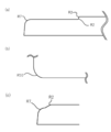
- FIG. 1 is a diagram schematically showing a laminated complex according to the present embodiment.
- the laminated composite 10 of the present embodiment is used for automobile members, electronic device members, and the like.
- the laminated composite 10 of the present embodiment may be used as a flat plate, or may be formed by press molding or the like under heating and / or pressure.
- the laminated composite 10 of the present embodiment includes a carbon fiber reinforced resin 110 and a steel plate 120 laminated on at least one surface of the carbon fiber reinforced resin 110.
- the steel plate 120 has a two-layer structure laminated on one side of the carbon fiber reinforced resin 110 described above, but the present invention is not limited to this. That is, the steel plate 120 may be laminated on both sides of the carbon fiber reinforced resin 110 to form a three-layer structure. Further, the carbon fiber reinforced resin 110 and the steel plate 120 may be alternately laminated to form a multilayer structure.
- the laminated composite 10 in the present embodiment is characterized by having a flexural modulus of 30 GPa or more on a flat plate.
- the reason for this is as follows. That is, in general, when manufacturing a molded product using carbon fiber reinforced resin, secondary processing is possible as an advantage of thermoplastic resin, so a press mold is used for flat carbon fiber reinforced resin. There were many press moldings. However, the present inventors have found that when the molded product is manufactured by the above method, the bending elastic modulus of the molded product is lower than that of the flat plate shape as a demerit of the secondary processing.
- the housing is made of resin only, it is necessary to increase the wall thickness in order to improve the rigidity, but by laminating the metal, the rigidity of the entire laminated body is improved without increasing the wall thickness of the resin part. be able to.
- the upper limit of the housing thickness is often set, so that it is an advantage that the rigidity as a whole can be improved without making the resin thick, but in order to improve this rigidity.
- One method is to improve the flexural modulus of the material.
- the present inventors have repeated studies for improving the flexural modulus even in the state of the flat plate before molding in order to improve the flexural modulus to some extent even in the molded product obtained by the secondary processing.
- the reason why the flexural modulus of the molded product is lower than that of the flat plate is not yet clear, but it is presumed that the material flow of the carbon fiber reinforced resin during the secondary processing affects the flexural modulus.
- the flexural modulus can be improved in the flat state as compared with the case of using only the carbon fiber reinforced resin by forming a laminated composite in which the carbon fiber reinforced resin and the steel plate are laminated. Furthermore, it was found that when the molded product is manufactured by secondary processing, the flexural modulus is unavoidably reduced as compared with the flat plate, but the flexural modulus is improved as compared with the case where only the carbon fiber reinforced resin is used. This is what led to the present invention.
- the flexural modulus of the molded body is set to a predetermined value or more even when an automobile member or the like is manufactured by secondary processing. can do.
- the value of the flexural modulus of the present embodiment can be obtained according to ASTM D-790.
- the specific flexural modulus is preferably 20 or more from the same viewpoint as described above.
- the specific flexural modulus is a value obtained by dividing the flexural modulus obtained as described above by the specific gravity of the laminated composite 10.
- the thickness of the laminated composite 10 of the present embodiment is not particularly limited and can be appropriately changed depending on the intended use, but for example, it is preferably about 0.3 mm to 3.0 mm from the viewpoint of physical properties and moldability. ..
- Carbon fiber reinforced resin 110 used for the laminated composite 10 of the present embodiment will be described.
- the carbon fiber reinforced resin 110 a carbon fiber reinforced resin in which the chopped strand prepreg impregnated with carbon fibers is oriented so as to exhibit pseudo isotropic properties is applied.
- the carbon fibers specifically used may be pitch-based carbon fibers or PAN-based carbon fibers, but are preferably PAN-based carbon fibers from the viewpoint of handleability. ..
- the filament diameter of one carbon fiber is usually 5 to 8 ⁇ m, and a fiber bundle in which a plurality of carbon fibers are aggregated in a flat shape with a predetermined number of filaments is preferably used.
- the number of filaments of the carbon fiber is 3,000 to 600,000, more preferably 6,000 to 24,000, from the viewpoint of productivity of prepreg production.
- the carbon fiber may be used alone or in combination with a reinforcing fiber other than the carbon fiber. Examples of the reinforcing fibers that can be combined include known fibers such as aramid fiber, polyethylene fiber, glass fiber, metal fiber, and natural fiber.
- the carbon fibers used in the laminated composite 10 of the present embodiment are preferably opened from the viewpoint of easily increasing the penetration of the matrix resin during the production of the prepreg, and when a reinforcing fiber other than the carbon fibers is used in combination. It is preferable that reinforcing fibers other than the carbon fibers are also opened.
- the resin used for the carbon fiber reinforced resin 110 it is preferable that it is a thermoplastic resin from the viewpoint of processability and the like as described above.
- the thermoplastic resin a known thermoplastic resin used as a matrix of fiber reinforced resins can be applied.
- a thermoplastic epoxy resin that is polymerized in the field, and from the viewpoint of high permeability to fibers during prepreg production and adhesiveness to the steel plate used in the present embodiment, bisphenol A type epoxy. It is particularly preferable to use a resin.
- the carbon fiber reinforced resin 110 used in this embodiment can be obtained as follows. That is, a unidirectional prepreg (for example, UD (Uni-Directional) tape) obtained by impregnating the above-mentioned carbon fiber into a thermoplastic resin cut to a predetermined length (chopped strand prepreg) is randomly sprayed and laminated.
- the carbon fiber reinforced resin 110 of the present embodiment can be obtained by softening the resin by heating and fixing the tape pieces to each other.
- the carbon fiber reinforced resin 110 can also be obtained by a method in which tape pieces are randomly laminated and then heated and pressed, or a method in which the laminated composite 10 is directly sprayed and laminated in a mold.
- the unidirectional prepreg used for the carbon fiber reinforced resin 110 of the present embodiment is a state in which the thermoplastic resin is uniformly impregnated in the prepreg production without containing voids (air bubbles or the like) between the fibers. It is preferable to use it. As a result, the adhesion of the unidirectional prepreg in the obtained carbon fiber reinforced resin 110 is enhanced, and the strength and isotropic properties of the laminated composite 10 can be enhanced.
- the fiber volume content Vf in the unidirectional prepreg is preferably controlled to be preferably 30 to 55%, more preferably 35 to 45%. It is preferable to set the above range from the viewpoint of improving the moldability of the molded product to be manufactured.
- the volume content exceeds the above upper limit value, the unimpregnated portion of the prepreg increases and it becomes difficult to make a voidless portion, which is not preferable. Further, if it is less than the lower limit value, it becomes difficult to secure the strength of the laminated complex 10, which is not preferable.
- the average length of the unidirectional prepreg with respect to the fiber direction is 10 to 50 mm, preferably 10 to 30 mm.
- the carbon fiber reinforced resin 110 By randomly laminating the chopped strand prepregs as described above, the carbon fiber reinforced resin 110 exhibits pseudo-isotropic properties, and the moldability of the resulting laminated composite 10 can be improved. Further, in the present embodiment, as the tape-shaped unidirectional prepreg described above, for example, those disclosed in Patent Document 1 can be used.
- the thickness of the carbon fiber reinforced resin 110 in the present embodiment is not particularly limited, but is preferably about 0.1 mm to 2.0 mm, for example, from the viewpoint of weight reduction. Further, the thickness of the carbon fiber reinforced resin may be appropriately changed according to the shape of the obtained molded product.
- the flexural modulus Gc of the carbon fiber reinforced resin 110 in the present embodiment is preferably 20 GPa or more from the viewpoint of the flexural modulus required for the laminated composite 10.
- the steel plate 120 As shown in FIG. 1, the steel plate 120 of the present embodiment may be laminated on at least one side of the carbon fiber reinforced resin 110 described above, or may be laminated on both sides of the carbon fiber reinforced resin 110 (not shown).
- the form may be a form in which both are alternately laminated in multiple layers.
- Examples of the steel plate 120 used in the laminated composite 10 of the present embodiment include known steel plates.
- As the steel sheet a hot-rolled steel sheet obtained by hot-rolling aluminum killed continuous cast steel to remove scale generated on the surface, or a cold-rolled steel sheet obtained by cold-rolling and quenching a hot-rolled steel sheet can be applied.
- the surface-treated steel sheet is required to have adhesion to the carbon fiber reinforced resin 110 (suppression of gaps at the laminated interface), control of the friction coefficient, and particularly formability by reducing the friction coefficient. It is more preferable from the viewpoint of improvement, corrosion resistance, and the like.
- the surface treatment include plating, chemical conversion treatment, resin coating, surface roughness, and the like, all of which can be preferably used.
- the plated steel sheet for example, a single-layer plating consisting of any one of Sn, Ni, Co, Mo, Zn, and Cr, or a plated steel sheet having two or more types of multi-layer plating or alloy plating (composite plating).
- composite plating composite plating
- Zn-plated steel sheets or Ni-plated steel sheets are particularly preferable.
- the Zn plating shall include Zn alloy plating
- the Ni plating shall include Ni alloy plating.
- chemical conversion treatment for example, known chemical conversion treatments such as chromate type, phosphoric acid type, vanadium acid type and silicic acid type can be applied.
- examples of the above-mentioned resin coating include known polyester resins, urethane resins, acrylic resins and the like.
- the surface roughness described above for example, in addition to temper rolling using a rolling roll having a predetermined surface roughness, the surface of the steel sheet is surfaced by using a known roughening technique such as blasting, chemical etching or laser irradiation. By roughening the surface, the adhesion between the steel plate 120 and the carbon fiber reinforced resin 110 can be improved by the anchor effect. In order to achieve both moldability and adhesion, it is preferable that the interface side of the steel sheet 120 with the carbon fiber reinforced resin 110 is roughened. On the other hand, the other surface (opposite side), which is the outer surface, may be smooth without being roughened from the viewpoint of reducing the friction coefficient and designability.
- the steel sheet 120 of the present embodiment is characterized in that its tensile elongation at break ( ⁇ ) is 20% or more. That is, the laminated composite 10 of the present embodiment is characterized in that, as described above, the flexural modulus and moldability in the flat plate state are shared at a high level. As a result of diligently repeating the experiments by the present inventors, the flexural modulus and formability were set to 30 GPa or more in the state of the laminated composite 10 in a flat plate state while the tensile elongation at break of the steel sheet 120 was set to 20% or more. It is shared at a high level.
- the thickness (plate thickness t) of the steel plate 120 of the present embodiment is preferably about 0.05 to 2.0 mm, preferably 0.05 to 0.50 mm, although it depends on the use of the obtained laminated composite 10 The range is particularly preferred. If the thickness of the steel sheet 120 is less than 0.05 mm, it is not preferable in manufacturing and handling. On the other hand, if it exceeds 2.0 mm, it becomes difficult to achieve the purpose such as weight reduction in the final molded product. In the present embodiment, the thickness ratio of the steel sheet 120 to the total thickness of the laminated composite 10 is preferably 1 to 50%, and further 1 to 20% improves weight reduction, strength, flexural modulus, and the like. It is particularly preferable from the viewpoint of achieving a high degree of compatibility.
- the steel plate 120 of the present embodiment preferably has a parameter S represented by the following calculation formula (1) of 7.5 or more, where ⁇ is the coefficient of friction on the surface (the surface in contact with the mold).
- S (steel plate thickness t x tensile elongation at break ⁇ ) / (coefficient of friction of steel plate ⁇ ) ... (1)
- the parameter S is 20 or more, more preferable results can be obtained from the viewpoint of moldability.
- the friction coefficient ⁇ of the steel sheet in the above formula (1) can be measured by a known friction coefficient measuring device. For example, specifically, it is possible to measure with a tribo gear surface surface measuring machine (TYPE: 14FW) manufactured by Shinto Kagaku Co., Ltd. As an example of the measurement conditions, the following conditions can be used. Load: 200g Measurement distance: 20 mm, Movement speed: 100 mm / min, Test environment: 200 ° C, Mating material: SUS304 ( ⁇ 10 mm) The coefficient of friction ⁇ can change depending on the roughness of the finished surface of the steel sheet, the surface treatment, and the like. For example, by lowering the coefficient of friction of the steel sheet in contact with the mold surface during the production of the molded body, the steel sheet easily flows into the mold, and the steel sheet after molding is less likely to be torn or wrinkled.
- a known friction coefficient measuring device for example, specifically, it is possible to measure with a tribo gear surface surface measuring machine (TYPE: 14FW) manufactured by Shin
- the temperature of the mold for the flat plate-shaped laminated complex is raised to 180 ° C. at 5 ° C./min.
- the carbon fiber reinforced resin 110 and the steel plate 120 are put into the mold and held at 180 ° C. and 0.5 MPa for 3 minutes, for example.
- it is pressed at 180 ° C. and 4 MPa for 12 minutes and naturally cooled.
- the load is removed (press is released), and the laminated composite 10 of the present embodiment can be obtained.
- the method for producing the flat plate-shaped laminated complex 10 is not limited to the above production conditions.
- a known production method can be applied as long as it has the characteristics of the laminated complex 10.
- a method of extruding a molten carbon fiber reinforced resin 110 onto a steel plate 120 or a method of laminating a heat adhesive film on a steel plate 120 and then thermocompression bonding the steel plate 120 with the heat adhesive film and the carbon fiber reinforced resin 110 is also applicable.
- the molded body 20 in the present embodiment is characterized in that it is molded by the laminated composite 10 described above. That is, the above-mentioned laminated composite 10 is used, for example, when a mold having a relatively small corner radius is used when a molded product is manufactured by press molding or the like under heating and / or pressure by a press molding method. Also, it is possible to suppress the occurrence of wrinkles, tears, and at least one gap at the laminated interface in the molded product.
- FIG. 2 shows an example of a mold MD as a molding die for manufacturing the molded body 20 of the present embodiment.
- FIG. 2A is a front view of the mold MD used for manufacturing the molded body 20 of the present embodiment
- FIG. 2B is a side view of the same.
- the die MD has a shoulder portion having a plurality of punch shoulder radii R. That is, FIG. 3 (a) is an enlarged view of the shoulder portion A in FIG. 2 (b), FIG. 3 (b) is an enlarged view of the shoulder portion B in FIG. 2 (a), and FIG. 3 (c). ) Is an enlarged view of the shoulder portion C in FIG. 2 (a) as viewed from the side.
- the shoulder portion A in the mold MD is R2, the shoulder portion B is R10, and the shoulder portion B is R2 and R7 in succession. Therefore, the mold MD has a shoulder portion having a plurality of shoulder radii. Includes.
- the molded body 20 is molded from the above-mentioned laminated composite 10 using the above-mentioned mold MD, the molded body 20 in the present embodiment is characterized by having a shoulder portion having a punch shoulder radius of 0 ⁇ R ⁇ 2. And. Further, it is preferable that this molded product is produced by one press molding. Further, the molded body 20 of the present embodiment preferably has a plurality of punch shoulder radii as shown in FIGS. 2 and 3.
- the laminated composite 10 of the present embodiment has the characteristics that the tensile elongation at break ⁇ of the steel sheet 120 is 20% or more and the flexural modulus of the flat plate is 30 GPa or more. Further, even if the laminated composite 10 of the present embodiment is molded using a mold having a shoulder portion having a small shoulder radius R like the mold MD shown in FIGS. 2 and 3, carbon fiber reinforced It is possible to suppress either the gap between the resin 110 and the steel plate 120 or wrinkles or tears in the steel plate 120, and improve the rigidity of the laminated composite without increasing the wall thickness of the resin portion.
- the mold suitable for this embodiment is not limited to the one shown in FIGS. 2 to 3, and any mold having a shoulder portion having a shoulder radius of 0 ⁇ R ⁇ 2 can be used for manufacturing the molded product 20 of the present embodiment. It goes without saying that it is applicable.
- a method for producing the molded body 20 described above a method of molding the laminated composite 10 described above by a press molding method using a molding die having a shoulder portion having a shoulder radius of 0 ⁇ R ⁇ 2 can be applied.
- a method of molding the carbon fiber reinforced resin 110 and the steel plate 120 described above by a press molding method using a molding die having a shoulder portion having a shoulder radius of 0 ⁇ R ⁇ 2 can be applied.
- the temperature of the mold for the molded product 20 is raised to 200 ° C. at 10 ° C./min. After the mold temperature reaches 200 ° C., the carbon fiber reinforced resin 110 and the steel plate 120 are put into the mold and held at 200 ° C. and 0.5 MPa for 1 minute. Then, press at 200 ° C. and 10 MPa for 5 minutes to cool naturally. When the mold temperature becomes 70 ° C. or lower, the load can be removed to obtain the molded product 20.
- the method for producing the molded product 20 is not limited to the above-mentioned production conditions, and a known production method can be applied as long as it has the above-mentioned characteristics of the molded product 20.
- the present embodiment is not limited to this. That is, the laminated composite 10 and the molded product 20 may be manufactured separately. At this time, it is also possible to first put each of the carbon fiber reinforced resin 110 and the steel plate 120 into the same mold to manufacture the laminated composite 10 and then to form the molded body 20 as a secondary process.
- Example 1 [Preparation of carbon fiber reinforced resin]
- a carbon fiber yarn PYROFIL TR50S15L: manufactured by Mitsubishi Chemical Corporation
- a hot-melted thermoplastic epoxy resin XNR / H6850V: manufactured by Nagase ChemteX Corporation
- a resin composition having a viscosity of 100 to 200 mPa ⁇ s. ..
- the obtained spread fiber tape is impregnated with the above resin composition, and then heated and solidified to form a tape-shaped unidirectional prepreg (fiber volume content (Vf): 40% ⁇ 2%).
- the obtained tape-shaped unidirectional prepreg was cut to a length of 13 mm to obtain a chopped strand prepreg.
- Chopped strand prepregs are sprayed and laminated in a mold so that the fiber directions are random (pseudo-isotropic), and then heated at 150 ° C. for 1 minute and 30 seconds to soften the resin contained in the chopped strand prepregs and tape pieces to each other.
- a carbon fiber reinforced resin (thickness: equivalent to 1.9 mm) was obtained by fixing the resin.
- the mold MD shown in FIG. 2 was prepared.
- This mold MD has a plurality of corners, and the R of each corner is R2, R7, and R10.
- the laminated composite obtained above was put into a mold MD heated to 200 ° C.
- the convex outer surface of the molded body was made into a steel plate.
- preheating was performed at 200 ° C. and 0.5 MPa for 1 minute, then pressing at 200 ° C. and 10 MPa for 5 minutes, cooling to 70 ° C., and then demolding to obtain a molded product.
- the flexural modulus was measured at a distance between fulcrums of 64 mm and a test speed of 3.4 mm / min, divided into 5 steel surfaces on the indenter side and 5 carbon surfaces.
- the average value of the flexural modulus obtained for 10 measurement samples is shown in Table 2 as the average flexural modulus.
- Table 2 also shows the specific flexural modulus. When the average flexural modulus was 30 or more, it was judged to be good.
- Table 1 shows the thickness of each of the carbon fiber reinforced resin and the steel plate.
- Table 1 shows the elongation by changing the annealing conditions of the steel sheet.
- the friction coefficient is also shown in Table 1.
- Table 1 shows the thickness of each of the carbon fiber reinforced resin and the steel plate.
- Table 1 shows the elongation by changing the annealing conditions of the steel sheet. The coefficient of friction is also shown in Table 1. Other than that, it was carried out in the same manner as in Example 1. The results are shown in Table 2.
- Table 1 shows the elongation by changing the annealing conditions of the steel sheet. The coefficient of friction is also shown in Table 1.
- a surface-treated steel sheet made of Zn—Co—Mo and subjected to composite Zn plating and phosphoric acid-based chemical conversion treatment was used. Other than that, it was carried out in the same manner as in Example 2. The results are shown in Table 2.
- Table 1 shows the elongation by changing the annealing conditions of the steel sheet.
- the coefficient of friction is also shown in Table 1.
- a surface-treated steel sheet having a composite Zn plating made of Zn—Co—Mo, a vanadium-based chemical conversion treatment, and a urethane resin coating was used. Other than that, it was carried out in the same manner as in Example 2. The results are shown in Table 2.
- Table 1 shows the elongation by changing the annealing conditions of the steel sheet.
- the coefficient of friction is also shown in Table 1.
- a surface-treated steel sheet having a composite Zn plating made of Zn—Co—Mo, a vanadium-based chemical conversion treatment, and an olefin-modified acrylic resin coating was used. Other than that, it was carried out in the same manner as in Example 2. The results are shown in Table 2.
- Example 7 In the production of the laminated composite, first, a heat-bonding film was heat-laminated on the steel sheet to prepare a steel sheet with a heat-bonding film. Next, the steel plate with the heat-bonding film and the carbon fiber reinforced resin were thermocompression-bonded to obtain a laminated composite. Then, the obtained laminated complex was pressed at 180 ° C. and 4 MPa for 12 minutes. After cooling to 70 ° C., unloading, unloading, and a laminated complex were obtained. Other than that, it was carried out in the same manner as in Example 2. The results are shown in Table 2.
- Table 1 shows the elongation by changing the annealing conditions of the steel sheet.
- the coefficient of friction is also shown in Table 1.
- Table 1 shows the elongation by changing the annealing conditions of the steel sheet.
- the coefficient of friction is also shown in Table 1.
- Table 1 shows the elongation by changing the annealing conditions of the steel sheet.
- the coefficient of friction is also shown in Table 1.
- Table 1 shows the elongation by changing the annealing conditions of the steel sheet.
- the coefficient of friction is also shown in Table 1.
- each example had characteristics such as favorable flexural modulus and moldability. On the other hand, in the comparative example, it was confirmed that none had this characteristic.
- the laminated composite of the present invention and the molded product using the same can be applied to a wide range of industries such as automobiles and electronic devices.
Abstract
[Problem] The purpose of the present invention is to provide a layered composite that has high levels of both flexural modulus and moldability. [Solution] A layered composite, characterized in comprising a carbon-fiber-reinforced resin in which a chopped strand prepreg, obtained by impregnating a resin with carbon fiber, is oriented so as to exhibit pseudo-isotropic properties, and a steel plate that is layered on at least one surface of the carbon-fiber-reinforced resin and has a tensile breakage elongation φ of 20% or higher, the flexural modulus of a flat plate obtained in compliance with ASTM D-790 being at least 30 GPa.
Description
本発明は、炭素繊維強化樹脂と金属との積層複合体に関する。
The present invention relates to a laminated composite of a carbon fiber reinforced resin and a metal.
従来、自動車部品や電子機器の筐体等として炭素繊維強化樹脂が用いられることが知られている。このような炭素繊維強化樹脂は、高い強度と成形性をあわせ持ち、金型プレス法やオートクレーブ法等により成形体が製造される。
Conventionally, it is known that carbon fiber reinforced resin is used as a housing for automobile parts and electronic devices. Such carbon fiber reinforced resin has both high strength and moldability, and a molded product is manufactured by a mold pressing method, an autoclave method, or the like.
例えば特許文献1では、プリプレグをランダムに積層するように配置させ加熱及び加工することにより製造される、等方性を示す炭素繊維強化樹脂が開示されている。このような炭素繊維強化樹脂は、一般的に、短時間での成形が可能なこと、2次加工が可能であること、あるいはリサイクルが行い易いこと、等の特徴を有している。これらの特徴により、比較的低コストで生産数が多く且つ複雑形状が要求される自動車部材や電子機器の部材用途として、注目され始めている。
For example, Patent Document 1 discloses an isotropic carbon fiber reinforced resin produced by arranging prepregs in a randomly laminated manner, heating and processing them. Such carbon fiber reinforced resins generally have features such as being able to be molded in a short time, being capable of secondary processing, and being easy to recycle. Due to these characteristics, it is beginning to attract attention as a member application for automobile parts and electronic devices, which requires a relatively low cost, a large number of production numbers, and a complicated shape.
一方で上記した特許文献1に記載のような炭素繊維強化樹脂は、強度及び成形性を併せ持つものであったが、他の重要なパラメータとして弾性率には未だ課題が残されていた。
On the other hand, the carbon fiber reinforced resin as described in Patent Document 1 described above has both strength and moldability, but there is still a problem in elastic modulus as another important parameter.
すなわち、特許文献1に記載のようなカット繊維を使用した炭素繊維強化樹脂は、それ自体である程度の強度及び成形性を併せ持つものの、かような炭素繊維強化樹脂のみでは等方性を維持しつつ弾性率も大きく向上させることは困難であった。一方で、上記した連続繊維など等方性を有さない炭素繊維強化樹脂に関しては、そもそも複雑な成形が不可能であるなど成形性の課題を有している。
That is, although the carbon fiber reinforced resin using the cut fiber as described in Patent Document 1 has a certain degree of strength and moldability by itself, the carbon fiber reinforced resin alone maintains the isotropic property. It was also difficult to greatly improve the elastic modulus. On the other hand, the carbon fiber reinforced resin having no isotropic property such as the above-mentioned continuous fiber has a problem of moldability such that complicated molding is impossible in the first place.
また近年、様々な用途に応じて複合材料が開発される中で、金属と繊維強化樹脂を接合した複合材料についても開発が進められている。例えば特許文献2~6には、鋼板やアルミニウム等の金属材料と繊維強化樹脂とを、接着剤等を介して又は介さずに積層した技術が開示されている。いずれの技術においても、比剛性や比強度を向上させ、あるいは軽量化および強度の向上等を目的として金属と繊維強化樹脂を接合した複合材料を提供しようとするものである。
In recent years, while composite materials have been developed for various purposes, the development of composite materials in which metal and fiber reinforced resin are bonded is also underway. For example, Patent Documents 2 to 6 disclose a technique in which a metal material such as a steel plate or aluminum and a fiber reinforced resin are laminated with or without an adhesive or the like. In any of the techniques, it is intended to provide a composite material in which a metal and a fiber reinforced resin are bonded for the purpose of improving the specific rigidity and the specific strength, or reducing the weight and the strength.
本発明は上記したように、金属と炭素繊維強化樹脂とを積層した複合材料において、曲げ弾性率と成形性を高い次元で共有する積層複合体を提供することを目的とする。特に、炭素繊維に熱可塑性樹脂を含浸させた等方性を有する炭素繊維強化樹脂と、この炭素繊維強化樹脂の少なくとも一面に積層された金属材料(鋼板)と、を有する積層複合体において、高い曲げ弾性率を有する積層複合体を提供すること、及び、その積層複合体を用いて高い曲げ弾性率を有する成形体を提供すること、を目的とする。
As described above, an object of the present invention is to provide a laminated composite material in which a metal and a carbon fiber reinforced resin are laminated, which shares a flexural modulus and moldability at a high level. In particular, it is high in a laminated composite having an isotropic carbon fiber reinforced resin in which carbon fibers are impregnated with a thermoplastic resin and a metal material (steel plate) laminated on at least one surface of the carbon fiber reinforced resin. An object of the present invention is to provide a laminated composite having a flexural modulus, and to provide a molded product having a high flexural modulus using the laminated composite.
本実施形態の積層複合体は、(1)炭素繊維に熱可塑性エポキシ樹脂を含浸させたチョップドストランドプリプレグを疑似等方性となるように配向・積層した炭素繊維強化樹脂と、前記炭素繊維強化樹脂の少なくとも一方の面に対して積層され、引張破断伸びφが20%以上である鋼板と、を備えた積層複合体において、ASTM D-790に準じて得た平板での曲げ弾性率が30GPa以上であり、実施例に示す要素型での前記積層複合体の成形性の評価において、パンチ肩半径0<R≦2において成形した際に前記鋼板におけるしわ・破れ・積層界面の隙間の少なくとも一つが生じていないことを特徴とする。
また本実施形態の積層複合体は、(2)炭素繊維が樹脂中に含浸されたチョップドストランドプリプレグが疑似等方性を示すように配向させた炭素繊維強化樹脂と、前記炭素繊維強化樹脂の少なくとも一方の面に対して積層され、引張破断伸びφが20%以上である鋼板と、を含み、ASTM D-790に準じて得た平板での曲げ弾性率が30GPa以上であることを特徴とする。
また本実施形態の積層複合体は、上記(2)において、(3)実施例に示す要素型での前記積層複合体の成形性の評価において、パンチ肩半径0<R≦2において成形した際に前記鋼板におけるしわ・破れ・積層界面の隙間の少なくとも一つが生じていないことが好ましい。
本実施形態の積層複合体は上記(1)~(3)のいずれかにおいて、(4)前記積層複合体の全体厚みに対する前記鋼板の厚み比率が1%~20%であることが好ましい。
本実施形態の積層複合体は上記(1)~(4)のいずれかにおいて、(5)前記鋼板は、下記式の値Sが7.5以上であることが好ましい。ただしここで、S=(鋼板の板厚t×引張破断伸びφ)/(鋼板の摩擦係数μ)である。
本実施形態の積層複合体は上記(1)~(5)のいずれかにおいて、(6)前記積層複合体の比曲げ弾性率が20以上25以下であることが好ましい。
本実施形態の積層複合体は上記(1)~(6)のいずれかにおいて、(7)前記鋼板が表面処理鋼板であり、表面処理がZn又はNiを含むめっきであることが好ましい。
本実施形態の成形体は、(8)上記(1)~(7)のいずれかの積層複合体により成形される成形体であって、肩半径0<R≦2の肩部を有することを特徴とする。 The laminated composite of the present embodiment comprises (1) a carbon fiber reinforced resin in which chopped strand prepregs in which carbon fibers are impregnated with a thermoplastic epoxy resin are oriented and laminated so as to be pseudo-isotropic, and the carbon fiber reinforced resin. In a laminated composite comprising a steel plate laminated on at least one surface of the above and having a tensile elongation at break φ of 20% or more, the flexural modulus of the flat plate obtained according to ASTM D-790 is 30 GPa or more. In the evaluation of the formability of the laminated composite in the element type shown in the examples, at least one of the wrinkles, tears, and gaps at the laminated interface in the steel plate was formed when the laminated composite was molded with a punch shoulder radius of 0 <R≤2. It is characterized in that it does not occur.
Further, the laminated composite of the present embodiment includes (2) a carbon fiber reinforced resin in which the chopped strand prepreg impregnated with carbon fibers is oriented so as to exhibit pseudo isotropic properties, and at least the carbon fiber reinforced resin. It is characterized by including a steel plate laminated on one surface and having a tensile elongation at break φ of 20% or more, and having a flexural modulus of 30 GPa or more on a flat plate obtained according to ASTM D-790. ..
Further, when the laminated composite of the present embodiment is molded with a punch shoulder radius of 0 <R ≦ 2 in the evaluation of the moldability of the laminated composite in the element type shown in (3) Example in the above (2). It is preferable that at least one of wrinkles, tears, and gaps at the laminated interface does not occur in the steel sheet.
In any of the above (1) to (3), the laminated composite of the present embodiment preferably has (4) a thickness ratio of the steel plate to the total thickness of the laminated complex of 1% to 20%.
In any of the above (1) to (4), the laminated composite of the present embodiment (5) preferably has a value S of the following formula of 7.5 or more. However, here, S = (plate thickness t of steel plate × tensile elongation at break φ) / (friction coefficient μ of steel plate).
In any of the above (1) to (5), the laminated composite of the present embodiment preferably has (6) a specific flexural modulus of 20 or more and 25 or less.
In any of the above (1) to (6), the laminated composite of the present embodiment preferably has (7) the steel sheet being a surface-treated steel sheet and the surface treatment being plating containing Zn or Ni.
The molded product of the present embodiment is (8) a molded product formed by the laminated composite according to any one of (1) to (7) above, and has a shoulder portion having a shoulder radius of 0 <R≤2. It is a feature.
本発明によれば、鋼板と炭素繊維強化樹脂とを積層した複合材料において、高い曲げ弾性率を有する積層複合体及び成形体を提供することが可能である。
According to the present invention, it is possible to provide a laminated composite and a molded product having a high flexural modulus in a composite material in which a steel plate and a carbon fiber reinforced resin are laminated.
≪積層複合体10≫
以下、本発明を実施するための実施形態について説明する。
図1は、本実施形態に係る積層複合体を模式的に示した図である。なお本実施形態の積層複合体10は、自動車部材や電子機器部材等に使用される。本実施形態の積層複合体10は、平板で使用してもよいし、加熱及び/又は加圧下においてプレス成形等の成形を施してもよい。 << Laminatedcomplex 10 >>
Hereinafter, embodiments for carrying out the present invention will be described.
FIG. 1 is a diagram schematically showing a laminated complex according to the present embodiment. The laminatedcomposite 10 of the present embodiment is used for automobile members, electronic device members, and the like. The laminated composite 10 of the present embodiment may be used as a flat plate, or may be formed by press molding or the like under heating and / or pressure.
以下、本発明を実施するための実施形態について説明する。
図1は、本実施形態に係る積層複合体を模式的に示した図である。なお本実施形態の積層複合体10は、自動車部材や電子機器部材等に使用される。本実施形態の積層複合体10は、平板で使用してもよいし、加熱及び/又は加圧下においてプレス成形等の成形を施してもよい。 << Laminated
Hereinafter, embodiments for carrying out the present invention will be described.
FIG. 1 is a diagram schematically showing a laminated complex according to the present embodiment. The laminated
本実施形態の積層複合体10は、図1に示されるように、炭素繊維強化樹脂110と、この炭素繊維強化樹脂110の少なくとも一方の面に積層された鋼板120を含む。なお図1においては、鋼板120は、上記した炭素繊維強化樹脂110の片面に積層された2層構造となっているが、本発明はこれに限られるものではない。
すなわち、炭素繊維強化樹脂110の両面に鋼板120が積層されて3層構造となっていてもよい。また、炭素繊維強化樹脂110と鋼板120とが交互に積層された多層構造となっていてもよい。 As shown in FIG. 1, the laminatedcomposite 10 of the present embodiment includes a carbon fiber reinforced resin 110 and a steel plate 120 laminated on at least one surface of the carbon fiber reinforced resin 110. In FIG. 1, the steel plate 120 has a two-layer structure laminated on one side of the carbon fiber reinforced resin 110 described above, but the present invention is not limited to this.
That is, thesteel plate 120 may be laminated on both sides of the carbon fiber reinforced resin 110 to form a three-layer structure. Further, the carbon fiber reinforced resin 110 and the steel plate 120 may be alternately laminated to form a multilayer structure.
すなわち、炭素繊維強化樹脂110の両面に鋼板120が積層されて3層構造となっていてもよい。また、炭素繊維強化樹脂110と鋼板120とが交互に積層された多層構造となっていてもよい。 As shown in FIG. 1, the laminated
That is, the
本実施形態における積層複合体10は、平板での曲げ弾性率が30GPa以上であることを特徴とする。この理由は以下のとおりである。
すなわち一般的に、炭素繊維強化樹脂を用いて成形体を製造する際には、熱可塑性樹脂の利点として二次加工が可能であるため、平板状の炭素繊維強化樹脂に対してプレス型を用いたプレス成形が多く行われていた。しかしながら、本発明者らが上記方法により成形体を製造する際において、二次加工のデメリットとして、平板状よりも成形体の方が曲げ弾性率が低下することを見出した。 The laminatedcomposite 10 in the present embodiment is characterized by having a flexural modulus of 30 GPa or more on a flat plate. The reason for this is as follows.
That is, in general, when manufacturing a molded product using carbon fiber reinforced resin, secondary processing is possible as an advantage of thermoplastic resin, so a press mold is used for flat carbon fiber reinforced resin. There were many press moldings. However, the present inventors have found that when the molded product is manufactured by the above method, the bending elastic modulus of the molded product is lower than that of the flat plate shape as a demerit of the secondary processing.
すなわち一般的に、炭素繊維強化樹脂を用いて成形体を製造する際には、熱可塑性樹脂の利点として二次加工が可能であるため、平板状の炭素繊維強化樹脂に対してプレス型を用いたプレス成形が多く行われていた。しかしながら、本発明者らが上記方法により成形体を製造する際において、二次加工のデメリットとして、平板状よりも成形体の方が曲げ弾性率が低下することを見出した。 The laminated
That is, in general, when manufacturing a molded product using carbon fiber reinforced resin, secondary processing is possible as an advantage of thermoplastic resin, so a press mold is used for flat carbon fiber reinforced resin. There were many press moldings. However, the present inventors have found that when the molded product is manufactured by the above method, the bending elastic modulus of the molded product is lower than that of the flat plate shape as a demerit of the secondary processing.
一方で、例えば精密部品を保護する電子機器筐体においては、薄肉化と剛性を共に向上させることが求められている。樹脂のみで筐体を作成した場合には剛性を向上させるために肉厚にする必要があるが、金属を積層させることにより樹脂部分を肉厚にすることなく積層体全体としての剛性を向上させることができる。例えばPC等の筐体においては筐体厚みの上限が決められていることが多いため、樹脂を肉厚にせずに全体としての剛性を向上できることはメリットとなるが、この剛性を向上させるための一つの方法としては、材料の曲げ弾性率を向上させることが挙げられる。
このため、本発明者らは、二次加工による成形体においてもある程度曲げ弾性率を向上させるため、成形前の平板の状態においても曲げ弾性率を向上させるための研究を繰り返した。
なお、平板よりも成形体の方が曲げ弾性率が低下する理由は未だ明らかではないが、二次加工時における炭素繊維強化樹脂の材料流動が曲げ弾性率に影響すると推察される。 On the other hand, for example, in an electronic device housing that protects precision parts, it is required to reduce the wall thickness and improve the rigidity. When the housing is made of resin only, it is necessary to increase the wall thickness in order to improve the rigidity, but by laminating the metal, the rigidity of the entire laminated body is improved without increasing the wall thickness of the resin part. be able to. For example, in a housing such as a PC, the upper limit of the housing thickness is often set, so that it is an advantage that the rigidity as a whole can be improved without making the resin thick, but in order to improve this rigidity. One method is to improve the flexural modulus of the material.
For this reason, the present inventors have repeated studies for improving the flexural modulus even in the state of the flat plate before molding in order to improve the flexural modulus to some extent even in the molded product obtained by the secondary processing.
The reason why the flexural modulus of the molded product is lower than that of the flat plate is not yet clear, but it is presumed that the material flow of the carbon fiber reinforced resin during the secondary processing affects the flexural modulus.
そして、炭素繊維強化樹脂と鋼板とを積層させた積層複合体とすることにより、平板の状態において、炭素繊維強化樹脂だけの場合よりも曲げ弾性率を向上可能であることを見出した。さらには、二次加工により成形体を製造した場合においては、平板と比較して曲げ弾性率の低下は免れないが、炭素繊維強化樹脂だけの場合よりも曲げ弾性率を向上させることを見出し、本発明に至ったものである。
Then, it was found that the flexural modulus can be improved in the flat state as compared with the case of using only the carbon fiber reinforced resin by forming a laminated composite in which the carbon fiber reinforced resin and the steel plate are laminated. Furthermore, it was found that when the molded product is manufactured by secondary processing, the flexural modulus is unavoidably reduced as compared with the flat plate, but the flexural modulus is improved as compared with the case where only the carbon fiber reinforced resin is used. This is what led to the present invention.
すなわち本実施形態における積層複合体10において、平板での曲げ弾性率が30GPa以上とすることにより、二次加工により自動車部材等を製造した場合においても成形体の曲げ弾性率を所定の値以上とすることができる。ここで、本実施形態の曲げ弾性率の値は、ASTM D-790に準じて得ることができる。
That is, in the laminated composite 10 of the present embodiment, by setting the flexural modulus of the flat plate to 30 GPa or more, the flexural modulus of the molded body is set to a predetermined value or more even when an automobile member or the like is manufactured by secondary processing. can do. Here, the value of the flexural modulus of the present embodiment can be obtained according to ASTM D-790.
なお、本実施形態の積層複合体10において、比曲げ弾性率は、上記と同様の観点から、20以上であることが好ましい。なお比曲げ弾性率は、上述のように得られた曲げ弾性率を積層複合体10の比重で割ることにより得られる値である。
本実施形態の積層複合体10の厚みとしては特に限定はされず、用途によって適宜変更可能であるが、例えば0.3mm~3.0mm程度であることが、物性と成形性の観点からは好ましい。 In the laminatedcomposite 10 of the present embodiment, the specific flexural modulus is preferably 20 or more from the same viewpoint as described above. The specific flexural modulus is a value obtained by dividing the flexural modulus obtained as described above by the specific gravity of the laminated composite 10.
The thickness of thelaminated composite 10 of the present embodiment is not particularly limited and can be appropriately changed depending on the intended use, but for example, it is preferably about 0.3 mm to 3.0 mm from the viewpoint of physical properties and moldability. ..
本実施形態の積層複合体10の厚みとしては特に限定はされず、用途によって適宜変更可能であるが、例えば0.3mm~3.0mm程度であることが、物性と成形性の観点からは好ましい。 In the laminated
The thickness of the
<炭素繊維強化樹脂110>
次に、本実施形態の積層複合体10に用いられる炭素繊維強化樹脂110について説明する。炭素繊維強化樹脂110としては、炭素繊維が樹脂中に含浸されたチョップドストランドプリプレグが疑似等方性を示すように配向させた炭素繊維強化樹脂が適用される。 <Carbon fiber reinforcedresin 110>
Next, the carbon fiber reinforcedresin 110 used for the laminated composite 10 of the present embodiment will be described. As the carbon fiber reinforced resin 110, a carbon fiber reinforced resin in which the chopped strand prepreg impregnated with carbon fibers is oriented so as to exhibit pseudo isotropic properties is applied.
次に、本実施形態の積層複合体10に用いられる炭素繊維強化樹脂110について説明する。炭素繊維強化樹脂110としては、炭素繊維が樹脂中に含浸されたチョップドストランドプリプレグが疑似等方性を示すように配向させた炭素繊維強化樹脂が適用される。 <Carbon fiber reinforced
Next, the carbon fiber reinforced
具体的に使用される炭素繊維としては、ピッチ系の炭素繊維であってもよいし、PAN系の炭素繊維であってもよいが、取扱い性の観点からPAN系の炭素繊維であることが好ましい。炭素繊維1本のフィラメント径は通常5~8μmであり、複数の炭素繊維が所定のフィラメント数で扁平状に集合した繊維束が好適に利用される。炭素繊維のフィラメント数は、プリプレグ製造の生産性の観点から3000~600000本、より好ましくは6000~24000本である。また、積層複合体10に用いる際には、炭素繊維単独で用いてもよいし、炭素繊維以外の強化繊維と組み合わせて用いてもよい。組み合わせ可能な強化繊維としては、アラミド繊維、ポリエチレン繊維、ガラス繊維、金属繊維、天然繊維、等の公知の繊維を挙げることができる。
The carbon fibers specifically used may be pitch-based carbon fibers or PAN-based carbon fibers, but are preferably PAN-based carbon fibers from the viewpoint of handleability. .. The filament diameter of one carbon fiber is usually 5 to 8 μm, and a fiber bundle in which a plurality of carbon fibers are aggregated in a flat shape with a predetermined number of filaments is preferably used. The number of filaments of the carbon fiber is 3,000 to 600,000, more preferably 6,000 to 24,000, from the viewpoint of productivity of prepreg production. Further, when used in the laminated composite 10, the carbon fiber may be used alone or in combination with a reinforcing fiber other than the carbon fiber. Examples of the reinforcing fibers that can be combined include known fibers such as aramid fiber, polyethylene fiber, glass fiber, metal fiber, and natural fiber.
本実施形態の積層複合体10に用いられる炭素繊維は、プリプレグ製造の際のマトリクス樹脂の浸透を高めやすい観点から開繊されていることが好ましく、炭素繊維以外の強化繊維を組み合わせて用いる場合には、その炭素繊維以外の強化繊維も開繊されていることが好ましい。
The carbon fibers used in the laminated composite 10 of the present embodiment are preferably opened from the viewpoint of easily increasing the penetration of the matrix resin during the production of the prepreg, and when a reinforcing fiber other than the carbon fibers is used in combination. It is preferable that reinforcing fibers other than the carbon fibers are also opened.
一方で、炭素繊維強化樹脂110に使用される樹脂としては、熱可塑性樹脂であることが上述のような加工性等の観点からは好ましい。熱可塑性樹脂としては、繊維強化樹脂のマトリクスとして用いられる公知の熱可塑性樹脂を適用することができる。具体的には、現場重合型である熱可塑性エポキシ樹脂を用いることが好ましく、プリプレグ製造の際の繊維への高い浸透性や本実施形態で使用する鋼板との接着性の観点からビスフェノールA型エポキシ樹脂を使用することが特に好ましい。
On the other hand, as the resin used for the carbon fiber reinforced resin 110, it is preferable that it is a thermoplastic resin from the viewpoint of processability and the like as described above. As the thermoplastic resin, a known thermoplastic resin used as a matrix of fiber reinforced resins can be applied. Specifically, it is preferable to use a thermoplastic epoxy resin that is polymerized in the field, and from the viewpoint of high permeability to fibers during prepreg production and adhesiveness to the steel plate used in the present embodiment, bisphenol A type epoxy. It is particularly preferable to use a resin.
本実施形態に用いられる炭素繊維強化樹脂110としては以下のように得ることができる。すなわち上述の炭素繊維を熱可塑性樹脂中に含浸して得られる一方向プリプレグ(例えばUD(Uni-Directional)テープ)を所定長さにカットしたもの(チョップドストランドプリプレグ)を、ランダムに散布して積層させた後、加熱することにより樹脂を軟化させてテープ片同士を固着することで、本実施形態の炭素繊維強化樹脂110を得ることができる。その他、テープ片をランダムに積層させた後、加熱してプレス加工する方法や、積層複合体10製造時に金型内に直接散布積層する方法などによっても炭素繊維強化樹脂110を得ることができる。
The carbon fiber reinforced resin 110 used in this embodiment can be obtained as follows. That is, a unidirectional prepreg (for example, UD (Uni-Directional) tape) obtained by impregnating the above-mentioned carbon fiber into a thermoplastic resin cut to a predetermined length (chopped strand prepreg) is randomly sprayed and laminated. The carbon fiber reinforced resin 110 of the present embodiment can be obtained by softening the resin by heating and fixing the tape pieces to each other. In addition, the carbon fiber reinforced resin 110 can also be obtained by a method in which tape pieces are randomly laminated and then heated and pressed, or a method in which the laminated composite 10 is directly sprayed and laminated in a mold.
また、本実施形態の炭素繊維強化樹脂110に使用される一方向プリプレグは、プリプレグ製造において、繊維間にボイド(気泡等)が含まれることなく熱可塑性樹脂が均一に含浸した状態となるものを使用することが好ましい。これにより、得られる炭素繊維強化樹脂110中の一方向プリプレグの密着性が高まり、積層複合体10の物性における強度及び等方性を高めることが可能となる。
Further, the unidirectional prepreg used for the carbon fiber reinforced resin 110 of the present embodiment is a state in which the thermoplastic resin is uniformly impregnated in the prepreg production without containing voids (air bubbles or the like) between the fibers. It is preferable to use it. As a result, the adhesion of the unidirectional prepreg in the obtained carbon fiber reinforced resin 110 is enhanced, and the strength and isotropic properties of the laminated composite 10 can be enhanced.
本実施形態の積層複合体10においては、一方向プリプレグにおける繊維体積含有率Vfが好ましくは30~55%、より好ましくは35~45%になるように制御されることが好ましい。上記した範囲とすることが製造する成形体の成形性を高める観点から好ましい。体積含有率が上記上限値を超えた場合、プリプレグの未含浸部が増えてボイドレス化が困難となるため好ましくない。また、下限値未満となると積層複合体10の強度を確保することが困難となるため好ましくない。
また一方向プリプレグの繊維方向に対する平均長さは10~50mm、好ましくは10~30mmである。 In thelaminated composite 10 of the present embodiment, the fiber volume content Vf in the unidirectional prepreg is preferably controlled to be preferably 30 to 55%, more preferably 35 to 45%. It is preferable to set the above range from the viewpoint of improving the moldability of the molded product to be manufactured. When the volume content exceeds the above upper limit value, the unimpregnated portion of the prepreg increases and it becomes difficult to make a voidless portion, which is not preferable. Further, if it is less than the lower limit value, it becomes difficult to secure the strength of the laminated complex 10, which is not preferable.
The average length of the unidirectional prepreg with respect to the fiber direction is 10 to 50 mm, preferably 10 to 30 mm.
また一方向プリプレグの繊維方向に対する平均長さは10~50mm、好ましくは10~30mmである。 In the
The average length of the unidirectional prepreg with respect to the fiber direction is 10 to 50 mm, preferably 10 to 30 mm.
なお、上記のようにチョップドストランドプリプレグをランダムに積層することにより、炭素繊維強化樹脂110は疑似等方性を示すようになり、その結果得られる積層複合体10の成形性が向上し得る。
また、本実施形態において、上記したテープ状の一方向プリプレグとしては、例えば特許文献1に開示されるものを使用することが可能である。
本実施形態における炭素繊維強化樹脂110の厚みは、特に限定されるものではないが、例えば0.1mm~2.0mm程度であることが、軽量化の観点からは好ましい。また、炭素繊維強化樹脂の厚みについては得られる成形体の形状に応じて適宜変更されてもよい。
本実施形態における炭素繊維強化樹脂110の曲げ弾性率Gcは、20GPa以上であることが、積層複合体10に要求される曲げ弾性率の観点からは好ましい。 By randomly laminating the chopped strand prepregs as described above, the carbon fiber reinforcedresin 110 exhibits pseudo-isotropic properties, and the moldability of the resulting laminated composite 10 can be improved.
Further, in the present embodiment, as the tape-shaped unidirectional prepreg described above, for example, those disclosed in Patent Document 1 can be used.
The thickness of the carbon fiber reinforcedresin 110 in the present embodiment is not particularly limited, but is preferably about 0.1 mm to 2.0 mm, for example, from the viewpoint of weight reduction. Further, the thickness of the carbon fiber reinforced resin may be appropriately changed according to the shape of the obtained molded product.
The flexural modulus Gc of the carbon fiber reinforcedresin 110 in the present embodiment is preferably 20 GPa or more from the viewpoint of the flexural modulus required for the laminated composite 10.
また、本実施形態において、上記したテープ状の一方向プリプレグとしては、例えば特許文献1に開示されるものを使用することが可能である。
本実施形態における炭素繊維強化樹脂110の厚みは、特に限定されるものではないが、例えば0.1mm~2.0mm程度であることが、軽量化の観点からは好ましい。また、炭素繊維強化樹脂の厚みについては得られる成形体の形状に応じて適宜変更されてもよい。
本実施形態における炭素繊維強化樹脂110の曲げ弾性率Gcは、20GPa以上であることが、積層複合体10に要求される曲げ弾性率の観点からは好ましい。 By randomly laminating the chopped strand prepregs as described above, the carbon fiber reinforced
Further, in the present embodiment, as the tape-shaped unidirectional prepreg described above, for example, those disclosed in Patent Document 1 can be used.
The thickness of the carbon fiber reinforced
The flexural modulus Gc of the carbon fiber reinforced
<鋼板120>
次に鋼板120について説明する。なお図1に示すように、本実施形態の鋼板120は、上述した炭素繊維強化樹脂110の少なくとも片面に積層されていてもよいし、図示はしないが炭素繊維強化樹脂110の両面に積層された形態、あるいは両者が交互に多層に積層された形態であってもよい。 <Steel plate 120>
Next, thesteel plate 120 will be described. As shown in FIG. 1, the steel plate 120 of the present embodiment may be laminated on at least one side of the carbon fiber reinforced resin 110 described above, or may be laminated on both sides of the carbon fiber reinforced resin 110 (not shown). The form may be a form in which both are alternately laminated in multiple layers.
次に鋼板120について説明する。なお図1に示すように、本実施形態の鋼板120は、上述した炭素繊維強化樹脂110の少なくとも片面に積層されていてもよいし、図示はしないが炭素繊維強化樹脂110の両面に積層された形態、あるいは両者が交互に多層に積層された形態であってもよい。 <
Next, the
本実施形態の積層複合体10に用いられる鋼板120としては、公知の鋼板が挙げられる。鋼板としては、アルミキルド連続鋳造鋼を熱間圧延し表面に生じたスケールを除去した熱延鋼板や、熱延鋼板を冷間圧延し焼鈍を施した冷延鋼板が適用できる。
Examples of the steel plate 120 used in the laminated composite 10 of the present embodiment include known steel plates. As the steel sheet, a hot-rolled steel sheet obtained by hot-rolling aluminum killed continuous cast steel to remove scale generated on the surface, or a cold-rolled steel sheet obtained by cold-rolling and quenching a hot-rolled steel sheet can be applied.
なお、本実施形態に用いる鋼板120としては、表面処理鋼板であることが、炭素繊維強化樹脂110との密着性(積層界面における隙間の抑制)、摩擦係数の制御、特に摩擦係数低減による成形性の向上、耐食性、等の観点からはより好ましい。表面処理としては、めっき、化成処理、樹脂被覆、あるいは表面粗化等が挙げられ、いずれも好適に使用できる。
As the steel sheet 120 used in the present embodiment, the surface-treated steel sheet is required to have adhesion to the carbon fiber reinforced resin 110 (suppression of gaps at the laminated interface), control of the friction coefficient, and particularly formability by reducing the friction coefficient. It is more preferable from the viewpoint of improvement, corrosion resistance, and the like. Examples of the surface treatment include plating, chemical conversion treatment, resin coating, surface roughness, and the like, all of which can be preferably used.
このうちめっき鋼板としては、例えばSn、Ni、Co、Mo、Zn、Crのいずれか一種からなる単層めっき、または二種以上からなる複層めっきや合金めっき(複合めっき)を施しためっき鋼板を用いることができる。このうち特に、Znめっき鋼板又はNiめっき鋼板が好ましい。この際、ZnめっきにはZn合金めっきを含むものとし、NiめっきにはNi合金めっきを含むものとする。
また、上記した化成処理としては、例えば公知のクロメート系、リン酸系、バナジウム酸系、ケイ酸系、等の化成処理等を適用可能である。
また、上記した樹脂被覆としては、例えば公知のポリエステル樹脂、ウレタン樹脂、アクリル樹脂等を挙げることができる。
また、上記した表面粗化としては、例えば、所定表面粗度の圧延ロールを用いた調質圧延の他、ブラスト処理や化学エッチングやレーザー照射などの公知の粗化技術を使って鋼板の表面を粗面化することで、アンカー効果により鋼板120と炭素繊維強化樹脂110との密着性を向上させることができる。
成形性と密着性を両立する上で、鋼板120における炭素繊維強化樹脂110との界面側は粗化することが好ましい。一方で外面となる他方の面(反対側)は、摩擦係数低減や意匠性などの観点から粗化せず平滑であってもよい。 Among these, as the plated steel sheet, for example, a single-layer plating consisting of any one of Sn, Ni, Co, Mo, Zn, and Cr, or a plated steel sheet having two or more types of multi-layer plating or alloy plating (composite plating). Can be used. Of these, Zn-plated steel sheets or Ni-plated steel sheets are particularly preferable. At this time, the Zn plating shall include Zn alloy plating, and the Ni plating shall include Ni alloy plating.
Further, as the above-mentioned chemical conversion treatment, for example, known chemical conversion treatments such as chromate type, phosphoric acid type, vanadium acid type and silicic acid type can be applied.
Further, examples of the above-mentioned resin coating include known polyester resins, urethane resins, acrylic resins and the like.
Further, as the surface roughness described above, for example, in addition to temper rolling using a rolling roll having a predetermined surface roughness, the surface of the steel sheet is surfaced by using a known roughening technique such as blasting, chemical etching or laser irradiation. By roughening the surface, the adhesion between thesteel plate 120 and the carbon fiber reinforced resin 110 can be improved by the anchor effect.
In order to achieve both moldability and adhesion, it is preferable that the interface side of thesteel sheet 120 with the carbon fiber reinforced resin 110 is roughened. On the other hand, the other surface (opposite side), which is the outer surface, may be smooth without being roughened from the viewpoint of reducing the friction coefficient and designability.
また、上記した化成処理としては、例えば公知のクロメート系、リン酸系、バナジウム酸系、ケイ酸系、等の化成処理等を適用可能である。
また、上記した樹脂被覆としては、例えば公知のポリエステル樹脂、ウレタン樹脂、アクリル樹脂等を挙げることができる。
また、上記した表面粗化としては、例えば、所定表面粗度の圧延ロールを用いた調質圧延の他、ブラスト処理や化学エッチングやレーザー照射などの公知の粗化技術を使って鋼板の表面を粗面化することで、アンカー効果により鋼板120と炭素繊維強化樹脂110との密着性を向上させることができる。
成形性と密着性を両立する上で、鋼板120における炭素繊維強化樹脂110との界面側は粗化することが好ましい。一方で外面となる他方の面(反対側)は、摩擦係数低減や意匠性などの観点から粗化せず平滑であってもよい。 Among these, as the plated steel sheet, for example, a single-layer plating consisting of any one of Sn, Ni, Co, Mo, Zn, and Cr, or a plated steel sheet having two or more types of multi-layer plating or alloy plating (composite plating). Can be used. Of these, Zn-plated steel sheets or Ni-plated steel sheets are particularly preferable. At this time, the Zn plating shall include Zn alloy plating, and the Ni plating shall include Ni alloy plating.
Further, as the above-mentioned chemical conversion treatment, for example, known chemical conversion treatments such as chromate type, phosphoric acid type, vanadium acid type and silicic acid type can be applied.
Further, examples of the above-mentioned resin coating include known polyester resins, urethane resins, acrylic resins and the like.
Further, as the surface roughness described above, for example, in addition to temper rolling using a rolling roll having a predetermined surface roughness, the surface of the steel sheet is surfaced by using a known roughening technique such as blasting, chemical etching or laser irradiation. By roughening the surface, the adhesion between the
In order to achieve both moldability and adhesion, it is preferable that the interface side of the
なお本実施形態の鋼板120は、その引張破断伸び(φ)が20%以上であることを特徴とする。すなわち、本実施形態の積層複合体10は、上述のように、平板の状態における曲げ弾性率と成形性とを高い次元で共有することを特徴とする。本発明者らが実験を鋭意繰り返した結果、鋼板120の引張破断伸びを20%以上としつつ、積層複合体10の平板の状態における曲げ弾性率を30GPa以上として、曲げ弾性率と成形性とを高い次元で共有させたものである。
The steel sheet 120 of the present embodiment is characterized in that its tensile elongation at break (φ) is 20% or more. That is, the laminated composite 10 of the present embodiment is characterized in that, as described above, the flexural modulus and moldability in the flat plate state are shared at a high level. As a result of diligently repeating the experiments by the present inventors, the flexural modulus and formability were set to 30 GPa or more in the state of the laminated composite 10 in a flat plate state while the tensile elongation at break of the steel sheet 120 was set to 20% or more. It is shared at a high level.
本実施形態の鋼板120の厚み(板厚t)は、得られる積層複合体10の用途にもよるが、0.05~2.0mm程度であることが好ましく、0.05~0.50mmの範囲であることが特に好ましい。鋼板120の厚みが0.05mm未満の場合には、製造や取り扱いにおいて好ましくない。一方で2.0mmを超えた場合には、最終的な成形品における軽量化等の目的を達成することが困難となる。
なお本実施形態において、積層複合体10の全体厚みに対する鋼板120の厚み比率は1~50%であることが好ましく、さらに1~20%であることが、軽量化、強度及び曲げ弾性率等を高度に両立させる観点からは特に好ましい。 The thickness (plate thickness t) of thesteel plate 120 of the present embodiment is preferably about 0.05 to 2.0 mm, preferably 0.05 to 0.50 mm, although it depends on the use of the obtained laminated composite 10 The range is particularly preferred. If the thickness of the steel sheet 120 is less than 0.05 mm, it is not preferable in manufacturing and handling. On the other hand, if it exceeds 2.0 mm, it becomes difficult to achieve the purpose such as weight reduction in the final molded product.
In the present embodiment, the thickness ratio of thesteel sheet 120 to the total thickness of the laminated composite 10 is preferably 1 to 50%, and further 1 to 20% improves weight reduction, strength, flexural modulus, and the like. It is particularly preferable from the viewpoint of achieving a high degree of compatibility.
なお本実施形態において、積層複合体10の全体厚みに対する鋼板120の厚み比率は1~50%であることが好ましく、さらに1~20%であることが、軽量化、強度及び曲げ弾性率等を高度に両立させる観点からは特に好ましい。 The thickness (plate thickness t) of the
In the present embodiment, the thickness ratio of the
さらに本実施形態の鋼板120は、その表面(金型と接する面)における摩擦係数をμとした場合、下記計算式(1)で表されるパラメータSが7.5以上であることが好ましい。
S=(鋼板の板厚t×引張破断伸びφ)/(鋼板の摩擦係数μ)・・・(1)
上記のように鋼板120によって炭素繊維強化樹脂110の曲げ弾性率を補強する必要があるが、上記パラメータSが7.5以上である場合、積層複合体10の好ましい成形性を得ることができる。上記パラメータSが20以上である場合、成形性の観点からさらに好ましい結果を得ることができる。 Further, thesteel plate 120 of the present embodiment preferably has a parameter S represented by the following calculation formula (1) of 7.5 or more, where μ is the coefficient of friction on the surface (the surface in contact with the mold).
S = (steel plate thickness t x tensile elongation at break φ) / (coefficient of friction of steel plate μ) ... (1)
As described above, it is necessary to reinforce the flexural modulus of the carbon fiber reinforcedresin 110 with the steel plate 120, but when the parameter S is 7.5 or more, the preferable moldability of the laminated composite 10 can be obtained. When the parameter S is 20 or more, more preferable results can be obtained from the viewpoint of moldability.
S=(鋼板の板厚t×引張破断伸びφ)/(鋼板の摩擦係数μ)・・・(1)
上記のように鋼板120によって炭素繊維強化樹脂110の曲げ弾性率を補強する必要があるが、上記パラメータSが7.5以上である場合、積層複合体10の好ましい成形性を得ることができる。上記パラメータSが20以上である場合、成形性の観点からさらに好ましい結果を得ることができる。 Further, the
S = (steel plate thickness t x tensile elongation at break φ) / (coefficient of friction of steel plate μ) ... (1)
As described above, it is necessary to reinforce the flexural modulus of the carbon fiber reinforced
なお、上記式(1)における鋼板の摩擦係数μは、公知の摩擦係数測定装置により測定可能である。例えば具体的には、新東科学(株)製のトライボギア表面性測定機(TYPE:14FW)等により測定することが可能である。測定条件の例としては、以下のような条件で行うことができる。
荷重:200g
測定距離:20mm、
移動速度:100mm/min、
試験環境:200℃、
相手材:SUS304(φ10mm)
なお、摩擦係数μは、鋼板の仕上げ面粗さや表面処理などにより変化し得る。例えば成形体製造の際の金型面と接する鋼板の摩擦係数を下げることで、鋼板が型内に流入しやすくなり、成形後の鋼板に破れやしわが生じ難くなる。 The friction coefficient μ of the steel sheet in the above formula (1) can be measured by a known friction coefficient measuring device. For example, specifically, it is possible to measure with a tribo gear surface surface measuring machine (TYPE: 14FW) manufactured by Shinto Kagaku Co., Ltd. As an example of the measurement conditions, the following conditions can be used.
Load: 200g
Measurement distance: 20 mm,
Movement speed: 100 mm / min,
Test environment: 200 ° C,
Mating material: SUS304 (φ10 mm)
The coefficient of friction μ can change depending on the roughness of the finished surface of the steel sheet, the surface treatment, and the like. For example, by lowering the coefficient of friction of the steel sheet in contact with the mold surface during the production of the molded body, the steel sheet easily flows into the mold, and the steel sheet after molding is less likely to be torn or wrinkled.
次に、本実施形態における積層複合体10(平板状)の製造方法の一例を以下に示す。
まず平板状の積層複合体用の金型を180℃まで5℃/minで昇温する。金型温度が180℃に達した後に、炭素繊維強化樹脂110と鋼板120とを金型内に投入し、例えば180℃、0.5MPaで3分間保持する。次いで、例えば180℃、4MPaで12分間プレスし、自然に冷却する。そして金型温度が70℃以下になったら除荷(プレスを解除)し、本実施形態の積層複合体10を得ることができる。
なお、平板状の積層複合体10の製造方法は、上記製造条件に限られるものではない。積層複合体10の特徴を有する限りにおいて公知の製造方法を適用可能である。例えば、鋼板120の上に溶融した炭素繊維強化樹脂110を押し出す方法や、鋼板120に熱接着フィルムをラミネートした後に、該熱接着フィルム付の鋼板120と炭素繊維強化樹脂110とを熱圧着して積層複合体10とする方法等も適用可能である。 Next, an example of the method for producing the laminated composite 10 (flat plate) in the present embodiment is shown below.
First, the temperature of the mold for the flat plate-shaped laminated complex is raised to 180 ° C. at 5 ° C./min. After the mold temperature reaches 180 ° C., the carbon fiber reinforcedresin 110 and the steel plate 120 are put into the mold and held at 180 ° C. and 0.5 MPa for 3 minutes, for example. Then, for example, it is pressed at 180 ° C. and 4 MPa for 12 minutes and naturally cooled. Then, when the mold temperature becomes 70 ° C. or lower, the load is removed (press is released), and the laminated composite 10 of the present embodiment can be obtained.
The method for producing the flat plate-shaped laminated complex 10 is not limited to the above production conditions. A known production method can be applied as long as it has the characteristics of the laminated complex 10. For example, a method of extruding a molten carbon fiber reinforcedresin 110 onto a steel plate 120 or a method of laminating a heat adhesive film on a steel plate 120 and then thermocompression bonding the steel plate 120 with the heat adhesive film and the carbon fiber reinforced resin 110. A method of forming the laminated composite 10 or the like is also applicable.
まず平板状の積層複合体用の金型を180℃まで5℃/minで昇温する。金型温度が180℃に達した後に、炭素繊維強化樹脂110と鋼板120とを金型内に投入し、例えば180℃、0.5MPaで3分間保持する。次いで、例えば180℃、4MPaで12分間プレスし、自然に冷却する。そして金型温度が70℃以下になったら除荷(プレスを解除)し、本実施形態の積層複合体10を得ることができる。
なお、平板状の積層複合体10の製造方法は、上記製造条件に限られるものではない。積層複合体10の特徴を有する限りにおいて公知の製造方法を適用可能である。例えば、鋼板120の上に溶融した炭素繊維強化樹脂110を押し出す方法や、鋼板120に熱接着フィルムをラミネートした後に、該熱接着フィルム付の鋼板120と炭素繊維強化樹脂110とを熱圧着して積層複合体10とする方法等も適用可能である。 Next, an example of the method for producing the laminated composite 10 (flat plate) in the present embodiment is shown below.
First, the temperature of the mold for the flat plate-shaped laminated complex is raised to 180 ° C. at 5 ° C./min. After the mold temperature reaches 180 ° C., the carbon fiber reinforced
The method for producing the flat plate-shaped laminated complex 10 is not limited to the above production conditions. A known production method can be applied as long as it has the characteristics of the laminated complex 10. For example, a method of extruding a molten carbon fiber reinforced
≪成形体20≫
次に本実施形態における成形体20について説明する。
本実施形態における成形体20は、上述した積層複合体10により成形されることを特徴とする。すなわち上述した積層複合体10は、例えばプレス成形法によって加熱及び/又は加圧下においてプレス成形等を施して成形体を製造する際に、角部のRが比較的小さい金型を用いた場合においても、成形体におけるしわ、破れ、積層界面の隙間の少なくとも1つの発生を抑制可能である。 << Molded body 20 >>
Next, the molded body 20 in this embodiment will be described.
The molded body 20 in the present embodiment is characterized in that it is molded by the laminated composite 10 described above. That is, the above-mentioned laminated composite 10 is used, for example, when a mold having a relatively small corner radius is used when a molded product is manufactured by press molding or the like under heating and / or pressure by a press molding method. Also, it is possible to suppress the occurrence of wrinkles, tears, and at least one gap at the laminated interface in the molded product.
図2に、本実施形態の成形体20を製造するための成形型としての金型MDの一例を示す。図2(a)は本実施形態の成形体20を製造するために使用される金型MDの正面図であり、図2(b)は同側面図である。
図2及び図3に示すように、金型MDは、複数のパンチ肩半径Rを有する肩部を有する。すなわち、図3(a)は図2(b)における肩部Aを拡大した図であり、図3(b)は図2(a)における肩部Bを拡大した図であり、図3(c)は図2(a)における肩部Cを側方向から見た拡大図である。図3に示すように、金型MDにおける肩部AはR2、肩部BはR10、肩部BはR2及びR7が連続しており、従って金型MDは複数の肩半径を有する肩部を含んでいる。 FIG. 2 shows an example of a mold MD as a molding die for manufacturing the molded body 20 of the present embodiment. FIG. 2A is a front view of the mold MD used for manufacturing the molded body 20 of the present embodiment, and FIG. 2B is a side view of the same.
As shown in FIGS. 2 and 3, the die MD has a shoulder portion having a plurality of punch shoulder radii R. That is, FIG. 3 (a) is an enlarged view of the shoulder portion A in FIG. 2 (b), FIG. 3 (b) is an enlarged view of the shoulder portion B in FIG. 2 (a), and FIG. 3 (c). ) Is an enlarged view of the shoulder portion C in FIG. 2 (a) as viewed from the side. As shown in FIG. 3, the shoulder portion A in the mold MD is R2, the shoulder portion B is R10, and the shoulder portion B is R2 and R7 in succession. Therefore, the mold MD has a shoulder portion having a plurality of shoulder radii. Includes.
このように、上記した金型MDを使用して上述した積層複合体10から成形されるため、本実施形態における成形体20は、パンチ肩半径0<R≦2の肩部を有することを特徴とする。また、この成形体は1回のプレス成形により製造されることが好ましい。また本実施形態の成形体20は、図2及び3に示すように複数のパンチ肩半径を有することが好ましい。
As described above, since the molded body 20 is molded from the above-mentioned laminated composite 10 using the above-mentioned mold MD, the molded body 20 in the present embodiment is characterized by having a shoulder portion having a punch shoulder radius of 0 <R ≦ 2. And. Further, it is preferable that this molded product is produced by one press molding. Further, the molded body 20 of the present embodiment preferably has a plurality of punch shoulder radii as shown in FIGS. 2 and 3.
ここで、本実施形態の積層複合体10は、鋼板120の引張破断伸びφが20%以上であり、平板での曲げ弾性率が30GPa以上という特徴を有している。また、本実施形態の積層複合体10は、図2及び図3に示した金型MDのように肩半径Rが小さい肩部を有した金型を用いて成形されたとしても、炭素繊維強化樹脂110と鋼板120との間の隙間、鋼板120におけるシワや破れ、のいずれかを抑制し、樹脂部分を肉厚にすることなく積層複合体としての剛性を向上させることが可能である。
なお、本実施形態に好適な金型は図2乃至図3に示すものに限られず、肩半径0<R≦2の肩部を有する金型であれば本実施形態の成形体20の製造に適用可能であることは言うまでもない。 Here, thelaminated composite 10 of the present embodiment has the characteristics that the tensile elongation at break φ of the steel sheet 120 is 20% or more and the flexural modulus of the flat plate is 30 GPa or more. Further, even if the laminated composite 10 of the present embodiment is molded using a mold having a shoulder portion having a small shoulder radius R like the mold MD shown in FIGS. 2 and 3, carbon fiber reinforced It is possible to suppress either the gap between the resin 110 and the steel plate 120 or wrinkles or tears in the steel plate 120, and improve the rigidity of the laminated composite without increasing the wall thickness of the resin portion.
The mold suitable for this embodiment is not limited to the one shown in FIGS. 2 to 3, and any mold having a shoulder portion having a shoulder radius of 0 <R ≦ 2 can be used for manufacturing the molded product 20 of the present embodiment. It goes without saying that it is applicable.
なお、本実施形態に好適な金型は図2乃至図3に示すものに限られず、肩半径0<R≦2の肩部を有する金型であれば本実施形態の成形体20の製造に適用可能であることは言うまでもない。 Here, the
The mold suitable for this embodiment is not limited to the one shown in FIGS. 2 to 3, and any mold having a shoulder portion having a shoulder radius of 0 <R ≦ 2 can be used for manufacturing the molded product 20 of the present embodiment. It goes without saying that it is applicable.
≪成形体の製造方法≫
上記した成形体20の製造方法としては、上述の積層複合体10を、肩半径0<R≦2の肩部を有する成形型を用いてプレス成形法により成形する方法が適用できる。
あるいは、上述した炭素繊維強化樹脂110と鋼板120とを、肩半径0<R≦2の肩部を有する成形型を用いてプレス成形法により成形する方法が適用できる。 ≪Manufacturing method of molded product≫
As a method for producing the molded body 20 described above, a method of molding the laminated composite 10 described above by a press molding method using a molding die having a shoulder portion having a shoulder radius of 0 <R ≦ 2 can be applied.
Alternatively, a method of molding the carbon fiber reinforcedresin 110 and the steel plate 120 described above by a press molding method using a molding die having a shoulder portion having a shoulder radius of 0 <R ≦ 2 can be applied.
上記した成形体20の製造方法としては、上述の積層複合体10を、肩半径0<R≦2の肩部を有する成形型を用いてプレス成形法により成形する方法が適用できる。
あるいは、上述した炭素繊維強化樹脂110と鋼板120とを、肩半径0<R≦2の肩部を有する成形型を用いてプレス成形法により成形する方法が適用できる。 ≪Manufacturing method of molded product≫
As a method for producing the molded body 20 described above, a method of molding the laminated composite 10 described above by a press molding method using a molding die having a shoulder portion having a shoulder radius of 0 <R ≦ 2 can be applied.
Alternatively, a method of molding the carbon fiber reinforced
本実施形態における成形体20の製造方法の一例を以下に示す。
まず成形体20用の金型を200℃まで10℃/minで昇温する。金型温度が200℃に達した後に、炭素繊維強化樹脂110と鋼板120とを金型内に投入し、200℃、0.5MPaで1分間保持する。次いで、200℃、10MPaで5分間プレスし、自然に冷却する。金型温度が70℃以下になったら除荷し、成形体20を得ることができる。
なお、成形体20の製造方法は上記製造条件に限られるものではなく、上述した成形体20特徴を有する限りにおいて公知の製造方法を適用可能である。 An example of the manufacturing method of the molded body 20 in this embodiment is shown below.
First, the temperature of the mold for the molded product 20 is raised to 200 ° C. at 10 ° C./min. After the mold temperature reaches 200 ° C., the carbon fiber reinforcedresin 110 and the steel plate 120 are put into the mold and held at 200 ° C. and 0.5 MPa for 1 minute. Then, press at 200 ° C. and 10 MPa for 5 minutes to cool naturally. When the mold temperature becomes 70 ° C. or lower, the load can be removed to obtain the molded product 20.
The method for producing the molded product 20 is not limited to the above-mentioned production conditions, and a known production method can be applied as long as it has the above-mentioned characteristics of the molded product 20.
まず成形体20用の金型を200℃まで10℃/minで昇温する。金型温度が200℃に達した後に、炭素繊維強化樹脂110と鋼板120とを金型内に投入し、200℃、0.5MPaで1分間保持する。次いで、200℃、10MPaで5分間プレスし、自然に冷却する。金型温度が70℃以下になったら除荷し、成形体20を得ることができる。
なお、成形体20の製造方法は上記製造条件に限られるものではなく、上述した成形体20特徴を有する限りにおいて公知の製造方法を適用可能である。 An example of the manufacturing method of the molded body 20 in this embodiment is shown below.
First, the temperature of the mold for the molded product 20 is raised to 200 ° C. at 10 ° C./min. After the mold temperature reaches 200 ° C., the carbon fiber reinforced
The method for producing the molded product 20 is not limited to the above-mentioned production conditions, and a known production method can be applied as long as it has the above-mentioned characteristics of the molded product 20.
また、上記した一例においては積層複合体10を経ずに成形体20を製造する例を示して説明したが、本実施形態はこれに限られるものではない。すなわち、積層複合体10と成形体20を別々に製造してもよい。この際、まず炭素繊維強化樹脂110と鋼板120の各々を同じ金型内に投入して積層複合体10を製造し、その後二次加工として成形体20を形成することも可能である。
Further, in the above-mentioned example, an example in which the molded body 20 is manufactured without passing through the laminated composite 10 has been described, but the present embodiment is not limited to this. That is, the laminated composite 10 and the molded product 20 may be manufactured separately. At this time, it is also possible to first put each of the carbon fiber reinforced resin 110 and the steel plate 120 into the same mold to manufacture the laminated composite 10 and then to form the molded body 20 as a secondary process.
以下に、実施例を挙げて本発明について、より具体的に説明する。
Hereinafter, the present invention will be described in more detail with reference to examples.
<実施例1>
[炭素繊維強化樹脂の準備]
まず、炭素繊維糸(PYROFIL TR50S15L:三菱ケミカル社製)を所定幅(15~17mm)に開繊させて、公知の開繊装置を用いて開繊テープを作成した。次に、熱溶融した熱可塑性エポキシ樹脂(XNR/H6850V:ナガセケムテックス社製)を用意し、攪拌機を用いて均一に混合して、100~200mPa・sの粘度を有する樹脂組成物を得た。得られた開繊テープに上記樹脂組成物を含浸させた後、加熱・固化しテープ状の一方向プリプレグ(繊維体積含有量(Vf):40%±2%)。得られたテープ状の一方向プリプレグを長さ13mmとなるようにカットしてチョップドストランドプリプレグとした。金型内にチョップドストランドプリプレグを繊維方向がランダムになるように(疑似等方性)散布積層させ、次いで150℃で1分30秒加熱しチョップドストランドプリプレグに含まれる樹脂を軟化させてテープ片同士を固着させることで炭素繊維強化樹脂(厚み:1.9mm相当)を得た。 <Example 1>
[Preparation of carbon fiber reinforced resin]
First, a carbon fiber yarn (PYROFIL TR50S15L: manufactured by Mitsubishi Chemical Corporation) was opened to a predetermined width (15 to 17 mm) to prepare a fiber-spreading tape using a known fiber-spreading device. Next, a hot-melted thermoplastic epoxy resin (XNR / H6850V: manufactured by Nagase ChemteX Corporation) was prepared and mixed uniformly using a stirrer to obtain a resin composition having a viscosity of 100 to 200 mPa · s. .. The obtained spread fiber tape is impregnated with the above resin composition, and then heated and solidified to form a tape-shaped unidirectional prepreg (fiber volume content (Vf): 40% ± 2%). The obtained tape-shaped unidirectional prepreg was cut to a length of 13 mm to obtain a chopped strand prepreg. Chopped strand prepregs are sprayed and laminated in a mold so that the fiber directions are random (pseudo-isotropic), and then heated at 150 ° C. for 1 minute and 30 seconds to soften the resin contained in the chopped strand prepregs and tape pieces to each other. A carbon fiber reinforced resin (thickness: equivalent to 1.9 mm) was obtained by fixing the resin.
[鋼板の準備]
厚さ0.1mmの冷延鋼板に、定法を用いてアルカリ電解脱脂処理及び硫酸酸洗処理を施した。引張弾性率、引張破断伸び(伸び)(%)、比重、摩擦係数、上述した計算式より得られるパラメータSは表1のとおりであった。 [Preparation of steel plate]
A cold-rolled steel sheet having a thickness of 0.1 mm was subjected to an alkaline electrolytic degreasing treatment and a sulfuric acid pickling treatment using a conventional method. Table 1 shows the tensile elastic modulus, the tensile elongation at break (elongation) (%), the specific gravity, the coefficient of friction, and the parameter S obtained from the above-mentioned calculation formula.
[積層複合体の製造]
上記した平板状積層複合体用の金型を180℃に加熱後、上記した炭素繊維強化樹脂と鋼板とを金型内に投入し、180℃、0.5MPaで3分間予備加熱を行った後、180℃、4MPaで12分プレスした。70℃になるまで冷却した後に、除荷、取出し、積層複合体を得た。 [Manufacturing of laminated complex]
After heating the above-mentioned mold for the flat laminated composite to 180 ° C., the above-mentioned carbon fiber reinforced resin and the steel plate are put into the mold, and preheating is performed at 180 ° C. and 0.5 MPa for 3 minutes. , 180 ° C., 4 MPa for 12 minutes. After cooling to 70 ° C., unloading, unloading, and a laminated complex were obtained.
[成形体の製造]
成形体用の金型として、図2に示す金型MDを用意した。この金型MDは、複数の角部を有しており、角部の各々のRとしてはR2、R7、及びR10、であった。
上記で得られた積層複合体を200℃に加熱した金型MD内に投入した。この際、成形体の凸形状の外面が鋼板となるようにした。投入後、200℃、0.5MPaで1分間予備加熱を行い、次いで、200℃、10MPaで5分プレスし、70℃まで冷却した後に脱型することにより成形体を得た。 [Manufacturing of molded products]
As a mold for the molded body, the mold MD shown in FIG. 2 was prepared. This mold MD has a plurality of corners, and the R of each corner is R2, R7, and R10.
The laminated composite obtained above was put into a mold MD heated to 200 ° C. At this time, the convex outer surface of the molded body was made into a steel plate. After charging, preheating was performed at 200 ° C. and 0.5 MPa for 1 minute, then pressing at 200 ° C. and 10 MPa for 5 minutes, cooling to 70 ° C., and then demolding to obtain a molded product.
[評価]
(A)曲げ物性(曲げ弾性率)評価
平板状の積層複合体に対して、以下のように曲げ弾性率を評価した。
積層複合体の平均曲げ弾性率は、ASTM D-790に従い、島津製作所製の精密万能試験機(オートグラフAG-100kNXplus)を用いて行った。具体的には、得られた平板状の積層複合体(平板)から、任意の長さ方向にて、長さ80±1.0mm、幅25±0.2mmの長方形の試料を切り出し、これを測定試料とした。同様にして全部で10本の測定試料を準備した。各々の測定試料について、支点間距離64mm、試験速度3.4mm/分で、圧子側をスチール面として5本、カーボン面で5本、に分けて、曲げ弾性率を測定した。10本の測定試料について得た曲げ弾性率の平均値を、平均曲げ弾性率として表2に示した。また比曲げ弾性率についても表2に示した。なお、平均曲げ弾性率が30以上であった場合に良好と判断できた。 [Evaluation]
(A) Evaluation of Bending Physical Properties (Bending Elastic Modulus) The flexural modulus was evaluated for a flat plate-shaped laminated composite as follows.
The average flexural modulus of the laminated composite was determined according to ASTM D-790 using a precision universal testing machine (Autograph AG-100kNXplus) manufactured by Shimadzu Corporation. Specifically, a rectangular sample having a length of 80 ± 1.0 mm and a width of 25 ± 0.2 mm is cut out from the obtained flat-plate-shaped laminated composite (flat plate) in an arbitrary length direction, and the sample is cut out. It was used as a measurement sample. In the same manner, a total of 10 measurement samples were prepared. For each measurement sample, the flexural modulus was measured at a distance between fulcrums of 64 mm and a test speed of 3.4 mm / min, divided into 5 steel surfaces on the indenter side and 5 carbon surfaces. The average value of the flexural modulus obtained for 10 measurement samples is shown in Table 2 as the average flexural modulus. Table 2 also shows the specific flexural modulus. When the average flexural modulus was 30 or more, it was judged to be good.
(B)成形性の評価
上記で得られた積層複合体により製造された成形体の成形性評価は、以下のように行った。すなわち得られた成形体の角部及び中央部分の絞り面に関して、(a)鋼板の破れがあるかどうか、(b)鋼板の表面にしわが生じているかどうか、(c)炭素繊維強化樹脂と鋼板との積層面に隙間が生じているかどうか、を目視で観察した。観察の結果、以下のように◎、○、×で評価し、表2に示した。
◎:角部及び中央部何れもしわや破れもなく、積層面に隙間も生じていない
○:角部にしわや破れ、隙間が生じている。
×:角部及び中央部にしわや破れ、隙間が生じている。 (B) Evaluation of Moldability The moldability of the molded product produced by the laminated composite obtained above was evaluated as follows. That is, regarding the drawn surfaces of the corners and the central portion of the obtained molded product, (a) whether the steel plate is torn, (b) whether the surface of the steel plate is wrinkled, and (c) carbon fiber reinforced resin and the steel plate. It was visually observed whether or not there was a gap on the laminated surface with the above. As a result of the observation, it was evaluated by ⊚, ◯, and × as follows, and is shown in Table 2.
⊚: There are no wrinkles or tears in the corners or the center, and there are no gaps in the laminated surface. ○: There are wrinkles, tears, or gaps in the corners.
X: Wrinkles, tears, and gaps are formed at the corners and the center.
<実施例2>
炭素繊維強化樹脂及び鋼板の各々の厚みを表1のとおりとした。鋼板の焼鈍条件を変えて伸びを表1のとおりとした。摩擦係数についても併せて表1に示す。それ以外は、実施例1と同様に行った。結果を表2に示す。 <Example 2>
Table 1 shows the thickness of each of the carbon fiber reinforced resin and the steel plate. Table 1 shows the elongation by changing the annealing conditions of the steel sheet. The friction coefficient is also shown in Table 1. Other than that, it was carried out in the same manner as in Example 1. The results are shown in Table 2.
<実施例3>
炭素繊維強化樹脂及び鋼板の各々の厚みを表1のとおりとした。鋼板の焼鈍条件を変えて伸びを表1のとおりとした。摩擦係数についても併せて表1に示す。それ以外は、実施例1と同様に行った。結果を表2に示す。 <Example 3>
Table 1 shows the thickness of each of the carbon fiber reinforced resin and the steel plate. Table 1 shows the elongation by changing the annealing conditions of the steel sheet. The coefficient of friction is also shown in Table 1. Other than that, it was carried out in the same manner as in Example 1. The results are shown in Table 2.
<実施例4>
鋼板の焼鈍条件を変えて伸びを表1のとおりとした。摩擦係数についても併せて表1に示す。鋼板として、Zn-Co-Moからなる複合Znめっき及びリン酸系化成処理を施した表面処理鋼板を使用した。それ以外は実施例2と同様に行った。結果を表2に示す。 <Example 4>
Table 1 shows the elongation by changing the annealing conditions of the steel sheet. The coefficient of friction is also shown in Table 1. As the steel sheet, a surface-treated steel sheet made of Zn—Co—Mo and subjected to composite Zn plating and phosphoric acid-based chemical conversion treatment was used. Other than that, it was carried out in the same manner as in Example 2. The results are shown in Table 2.
<実施例5>
鋼板の焼鈍条件を変えて伸びを表1のとおりとした。摩擦係数についても併せて表1に示す。鋼板として、Zn-Co-Moからなる複合Znめっき、バナジウム系化成処理及びウレタン樹脂被覆を施した表面処理鋼板を使用した。それ以外は実施例2と同様に行った。結果を表2に示す。 <Example 5>
Table 1 shows the elongation by changing the annealing conditions of the steel sheet. The coefficient of friction is also shown in Table 1. As the steel sheet, a surface-treated steel sheet having a composite Zn plating made of Zn—Co—Mo, a vanadium-based chemical conversion treatment, and a urethane resin coating was used. Other than that, it was carried out in the same manner as in Example 2. The results are shown in Table 2.
<実施例6>
鋼板の焼鈍条件を変えて伸びを表1のとおりとした。摩擦係数についても併せて表1に示す。鋼板として、Zn-Co-Moからなる複合Znめっき、バナジウム系化成処理及びオレフィン変性アクリル樹脂被覆を施した表面処理鋼板を使用した。それ以外は実施例2と同様に行った。結果を表2に示す。 <Example 6>
Table 1 shows the elongation by changing the annealing conditions of the steel sheet. The coefficient of friction is also shown in Table 1. As the steel sheet, a surface-treated steel sheet having a composite Zn plating made of Zn—Co—Mo, a vanadium-based chemical conversion treatment, and an olefin-modified acrylic resin coating was used. Other than that, it was carried out in the same manner as in Example 2. The results are shown in Table 2.
<実施例7>
積層複合体の製造において、まず鋼板に熱接着フィルムを熱ラミネートして熱接着フィルム付鋼板を作製した。次いでこの熱接着フィルム付鋼板と炭素繊維強化樹脂を熱圧着して積層複合体を得た。その後、得られた積層複合体を180℃、4MPaで12分プレスした。70℃になるまで冷却した後に、除荷、取出し、積層複合体を得た。それ以外は実施例2と同様に行った。結果を表2に示す。 <Example 7>
In the production of the laminated composite, first, a heat-bonding film was heat-laminated on the steel sheet to prepare a steel sheet with a heat-bonding film. Next, the steel plate with the heat-bonding film and the carbon fiber reinforced resin were thermocompression-bonded to obtain a laminated composite. Then, the obtained laminated complex was pressed at 180 ° C. and 4 MPa for 12 minutes. After cooling to 70 ° C., unloading, unloading, and a laminated complex were obtained. Other than that, it was carried out in the same manner as in Example 2. The results are shown in Table 2.
<実施例8>
鋼板の焼鈍条件を変えて伸びを表1のとおりとした。摩擦係数についても併せて表1に示す。それ以外は、実施例2と同様に行った。結果を表2に示す。 <Example 8>
Table 1 shows the elongation by changing the annealing conditions of the steel sheet. The coefficient of friction is also shown in Table 1. Other than that, it was carried out in the same manner as in Example 2. The results are shown in Table 2.
<比較例1>
炭素繊維強化樹脂の厚みを2.0mmとした点、鋼板を使用しなかった点以外は実施例1と同様に行った。結果を表2に示す。 <Comparative example 1>
The same procedure as in Example 1 was carried out except that the thickness of the carbon fiber reinforced resin was 2.0 mm and the steel plate was not used. The results are shown in Table 2.
炭素繊維強化樹脂の厚みを2.0mmとした点、鋼板を使用しなかった点以外は実施例1と同様に行った。結果を表2に示す。 <Comparative example 1>
The same procedure as in Example 1 was carried out except that the thickness of the carbon fiber reinforced resin was 2.0 mm and the steel plate was not used. The results are shown in Table 2.
<比較例2>
炭素繊維強化樹脂を、熱可塑性ポリプロピレン樹脂を含浸させた炭素繊維織物とした。厚み及び繊維体積含有量(Vf)は表1のとおりとした。それ以外は実施例2と同様に行った。結果を表2に示す。 <Comparative example 2>
The carbon fiber reinforced resin was made into a carbon fiber woven fabric impregnated with a thermoplastic polypropylene resin. The thickness and fiber volume content (Vf) are as shown in Table 1. Other than that, it was carried out in the same manner as in Example 2. The results are shown in Table 2.
<比較例3>
鋼板の焼鈍条件を変えて伸びを表1のとおりとした。摩擦係数についても併せて表1に示す。それ以外は、実施例2と同様に行った。結果を表2に示す。 <Comparative example 3>
Table 1 shows the elongation by changing the annealing conditions of the steel sheet. The coefficient of friction is also shown in Table 1. Other than that, it was carried out in the same manner as in Example 2. The results are shown in Table 2.
<比較例4>
鋼板の焼鈍条件を変えて伸びを表1のとおりとした。摩擦係数についても併せて表1に示す。それ以外は、実施例2と同様に行った。結果を表2に示す。 <Comparative example 4>
Table 1 shows the elongation by changing the annealing conditions of the steel sheet. The coefficient of friction is also shown in Table 1. Other than that, it was carried out in the same manner as in Example 2. The results are shown in Table 2.
<比較例5>
鋼板として厚さ0.1mmのアルミニウム板を用いた。伸び率等は表1に示すとおりとした。それ以外は実施例1と同様に行った。結果を表2に示す。 <Comparative example 5>
An aluminum plate having a thickness of 0.1 mm was used as the steel plate. The growth rate and the like are as shown in Table 1. Other than that, it was carried out in the same manner as in Example 1. The results are shown in Table 2.
<比較例6>
鋼板の焼鈍条件を変えて伸びを表1のとおりとした。摩擦係数についても併せて表1に示す。それ以外は、実施例2と同様に行った。結果を表2に示す。 <Comparative Example 6>
Table 1 shows the elongation by changing the annealing conditions of the steel sheet. The coefficient of friction is also shown in Table 1. Other than that, it was carried out in the same manner as in Example 2. The results are shown in Table 2.


各実施例は、好ましい曲げ弾性率や成形性等の特性を備えていることが確認された。一方で比較例においては、この特性を備えるものはなかったことが確認された。
It was confirmed that each example had characteristics such as favorable flexural modulus and moldability. On the other hand, in the comparative example, it was confirmed that none had this characteristic.
なお上記した実施形態と各実施例は、本発明の趣旨を逸脱しない範囲で種々の変形が可能である。また、上記した実施形態と実施例における積層複合体及びそれを用いた成形体は、主として自動車部材や電子機器の筐体等に用いられるものとして説明したが、それらの用途に限られず、例えば、放熱材や電磁波シールド材など他の用途にも適用が可能である。
The above-described embodiment and each embodiment can be modified in various ways without departing from the spirit of the present invention. Further, the laminated composites in the above-described embodiments and examples and the molded products using the same have been described as being mainly used for housings of automobile members and electronic devices, but are not limited to those uses, for example. It can also be applied to other applications such as heat dissipation materials and electromagnetic wave shielding materials.
以上説明したように、本発明の積層複合体及びそれを用いた成形体は、自動車や電子機器など広い分野の産業への適用が可能である。
As described above, the laminated composite of the present invention and the molded product using the same can be applied to a wide range of industries such as automobiles and electronic devices.
10 積層複合体
110 炭素繊維強化樹脂
120 鋼板
20 成形体
MD 金型 10 Laminated composite 110 Carbon fiber reinforcedresin 120 Steel plate 20 Molded MD mold
110 炭素繊維強化樹脂
120 鋼板
20 成形体
MD 金型 10 Laminated composite 110 Carbon fiber reinforced
Claims (7)
- 炭素繊維が樹脂中に含浸されたチョップドストランドプリプレグが疑似等方性を示すように配向させた炭素繊維強化樹脂と、
前記炭素繊維強化樹脂の少なくとも一方の面に対して積層され、引張破断伸びφが20%以上である鋼板と、を含み、
ASTM D-790に準じて得た平板での曲げ弾性率が30GPa以上であることを特徴とする、積層複合体。 A carbon fiber reinforced resin in which the chopped strand prepreg impregnated with carbon fibers is oriented so as to exhibit pseudo-isotropic properties,
A steel plate laminated on at least one surface of the carbon fiber reinforced resin and having a tensile elongation at break φ of 20% or more is included.
A laminated complex characterized by having a flexural modulus of 30 GPa or more on a flat plate obtained according to ASTM D-790. - 実施例に示す要素型での前記積層複合体の成形性の評価において、パンチ肩半径0<R≦2において成形した際に前記鋼板におけるしわ・破れ・積層界面の隙間の少なくとも一つが生じていない、請求項1に記載の積層複合体。 In the evaluation of the formability of the laminated composite in the element type shown in the examples, at least one of wrinkles, tears, and gaps at the laminated interface of the steel sheet did not occur when molding was performed with a punch shoulder radius of 0 <R≤2. , The laminated composite according to claim 1.
- 前記積層複合体の全体厚みに対する前記鋼板の厚み比率が、1%~20%である、請求項1又は2に記載の積層複合体。 The laminated composite according to claim 1 or 2, wherein the thickness ratio of the steel plate to the total thickness of the laminated composite is 1% to 20%.
- 前記鋼板は、下記式の値Sが7.5以上である、請求項1~3のいずれか一項に記載の積層複合体。
ただし、
S=(鋼板の板厚t×引張破断伸びφ)/(鋼板の摩擦係数μ) The laminated composite according to any one of claims 1 to 3, wherein the steel sheet has a value S of 7.5 or more in the following formula.
However,
S = (steel plate thickness t x tensile elongation at break φ) / (steel plate friction coefficient μ) - 前記積層複合体の比曲げ弾性率が20以上である、請求項1~4のいずれか一項に記載の積層複合体。 The laminated composite according to any one of claims 1 to 4, wherein the laminated composite has a specific flexural modulus of 20 or more.
- 前記鋼板が表面処理鋼板であり、表面処理がZn又はNiを含むめっきである、請求項1~5のいずれか一項に記載の積層複合体。 The laminated composite according to any one of claims 1 to 5, wherein the steel sheet is a surface-treated steel sheet and the surface treatment is plating containing Zn or Ni.
- 請求項1~6のいずれか一項に記載の積層複合体により成形される成形体であって、肩半径0<R≦2の肩部を有することを特徴とする、成形体。
A molded product formed by the laminated composite according to any one of claims 1 to 6, wherein the molded product has a shoulder portion having a shoulder radius of 0 <R ≦ 2.
Priority Applications (4)
| Application Number | Priority Date | Filing Date | Title |
|---|---|---|---|
| EP20896177.1A EP4070946A4 (en) | 2019-12-02 | 2020-12-01 | Layered composite |
| JP2021562652A JPWO2021112077A1 (en) | 2019-12-02 | 2020-12-01 | |
| US17/781,197 US20230001652A1 (en) | 2019-12-02 | 2020-12-01 | Layered composite |
| CN202080081966.6A CN114761225A (en) | 2019-12-02 | 2020-12-01 | Laminated composite body |
Applications Claiming Priority (2)
| Application Number | Priority Date | Filing Date | Title |
|---|---|---|---|
| JP2019218335 | 2019-12-02 | ||
| JP2019-218335 | 2019-12-02 |
Publications (1)
| Publication Number | Publication Date |
|---|---|
| WO2021112077A1 true WO2021112077A1 (en) | 2021-06-10 |
Family
ID=76222412
Family Applications (1)
| Application Number | Title | Priority Date | Filing Date |
|---|---|---|---|
| PCT/JP2020/044663 WO2021112077A1 (en) | 2019-12-02 | 2020-12-01 | Layered composite |
Country Status (5)
| Country | Link |
|---|---|
| US (1) | US20230001652A1 (en) |
| EP (1) | EP4070946A4 (en) |
| JP (1) | JPWO2021112077A1 (en) |
| CN (1) | CN114761225A (en) |
| WO (1) | WO2021112077A1 (en) |
Cited By (1)
| Publication number | Priority date | Publication date | Assignee | Title |
|---|---|---|---|---|
| WO2023231949A1 (en) * | 2022-05-31 | 2023-12-07 | 比亚迪股份有限公司 | Battery protective bottom plate, battery pack composite protective structure, and vehicle |
Citations (11)
| Publication number | Priority date | Publication date | Assignee | Title |
|---|---|---|---|---|
| JPS5634641B2 (en) | 1975-01-31 | 1981-08-12 | ||
| JPS592839A (en) * | 1982-06-09 | 1984-01-09 | グリコ・アクチエンゲゼルシヤフト | Laminated composite material and its manufacture |
| JP2006076060A (en) * | 2004-09-08 | 2006-03-23 | Toray Ind Inc | Under cover for moving body and its manufacturing method |
| JP2010089394A (en) | 2008-10-08 | 2010-04-22 | Nisshin Steel Co Ltd | Plate-like composite material and long fiber knitted sheet |
| JP2010150390A (en) | 2008-12-25 | 2010-07-08 | Kyocera Chemical Corp | Metal foil laminated carbon fiber cloth prepreg for press working and carbon fiber cloth renforced plastic molded article |
| JP2011056748A (en) * | 2009-09-09 | 2011-03-24 | Toyota Motor Corp | Steel sheet reinforcing material |
| JP2012109452A (en) | 2010-11-18 | 2012-06-07 | Mitsubishi Plastics Inc | Electromagnetic-wave shielding composite material, electronic device housing, and battery case |
| WO2017090676A1 (en) * | 2015-11-25 | 2017-06-01 | 三菱樹脂株式会社 | Laminated panel and method for manufacturing article molded therefrom |
| WO2017115640A1 (en) * | 2015-12-28 | 2017-07-06 | 東レ株式会社 | Sandwich structure, molded object, and production processes therefor |
| JP6176691B1 (en) | 2016-10-07 | 2017-08-09 | サンコロナ小田株式会社 | Unidirectional prepreg and fiber reinforced thermoplastic resin sheet |
| JP2019119213A (en) | 2017-12-28 | 2019-07-22 | 日本製鉄株式会社 | Metal-fiber reinforced resin material composite and manufacturing method therefor |
Family Cites Families (6)
| Publication number | Priority date | Publication date | Assignee | Title |
|---|---|---|---|---|
| JPH0771804B2 (en) * | 1990-10-12 | 1995-08-02 | 株式会社神戸製鋼所 | Carbon fiber prepreg and carbon fiber reinforced resin |
| JPH11227103A (en) * | 1998-02-13 | 1999-08-24 | Kawasaki Steel Corp | Laminate |
| EP1927618A4 (en) * | 2005-08-18 | 2010-01-13 | Teijin Techno Products Ltd | Isotopic fiber-reinforced thermoplastic resin sheet, and process for production and molded plate thereof |
| JP2011037002A (en) * | 2007-12-14 | 2011-02-24 | Nippon Zeon Co Ltd | Metal/fiber-reinforced resin composite and process for producing the same |
| KR102008540B1 (en) * | 2011-07-28 | 2019-08-07 | 미쯔비시 케미컬 주식회사 | Carbon-fiber-reinforced carbon composite and method of manufacturing same |
| JP2013208725A (en) * | 2012-03-30 | 2013-10-10 | Mitsubishi Rayon Co Ltd | Carbon fiber-reinforced thermoplastic resin laminated body and method of producing the same |
-
2020
- 2020-12-01 US US17/781,197 patent/US20230001652A1/en active Pending
- 2020-12-01 EP EP20896177.1A patent/EP4070946A4/en active Pending
- 2020-12-01 WO PCT/JP2020/044663 patent/WO2021112077A1/en unknown
- 2020-12-01 JP JP2021562652A patent/JPWO2021112077A1/ja active Pending
- 2020-12-01 CN CN202080081966.6A patent/CN114761225A/en active Pending
Patent Citations (11)
| Publication number | Priority date | Publication date | Assignee | Title |
|---|---|---|---|---|
| JPS5634641B2 (en) | 1975-01-31 | 1981-08-12 | ||
| JPS592839A (en) * | 1982-06-09 | 1984-01-09 | グリコ・アクチエンゲゼルシヤフト | Laminated composite material and its manufacture |
| JP2006076060A (en) * | 2004-09-08 | 2006-03-23 | Toray Ind Inc | Under cover for moving body and its manufacturing method |
| JP2010089394A (en) | 2008-10-08 | 2010-04-22 | Nisshin Steel Co Ltd | Plate-like composite material and long fiber knitted sheet |
| JP2010150390A (en) | 2008-12-25 | 2010-07-08 | Kyocera Chemical Corp | Metal foil laminated carbon fiber cloth prepreg for press working and carbon fiber cloth renforced plastic molded article |
| JP2011056748A (en) * | 2009-09-09 | 2011-03-24 | Toyota Motor Corp | Steel sheet reinforcing material |
| JP2012109452A (en) | 2010-11-18 | 2012-06-07 | Mitsubishi Plastics Inc | Electromagnetic-wave shielding composite material, electronic device housing, and battery case |
| WO2017090676A1 (en) * | 2015-11-25 | 2017-06-01 | 三菱樹脂株式会社 | Laminated panel and method for manufacturing article molded therefrom |
| WO2017115640A1 (en) * | 2015-12-28 | 2017-07-06 | 東レ株式会社 | Sandwich structure, molded object, and production processes therefor |
| JP6176691B1 (en) | 2016-10-07 | 2017-08-09 | サンコロナ小田株式会社 | Unidirectional prepreg and fiber reinforced thermoplastic resin sheet |
| JP2019119213A (en) | 2017-12-28 | 2019-07-22 | 日本製鉄株式会社 | Metal-fiber reinforced resin material composite and manufacturing method therefor |
Non-Patent Citations (1)
| Title |
|---|
| See also references of EP4070946A4 |
Cited By (1)
| Publication number | Priority date | Publication date | Assignee | Title |
|---|---|---|---|---|
| WO2023231949A1 (en) * | 2022-05-31 | 2023-12-07 | 比亚迪股份有限公司 | Battery protective bottom plate, battery pack composite protective structure, and vehicle |
Also Published As
| Publication number | Publication date |
|---|---|
| US20230001652A1 (en) | 2023-01-05 |
| JPWO2021112077A1 (en) | 2021-06-10 |
| EP4070946A4 (en) | 2024-01-10 |
| CN114761225A (en) | 2022-07-15 |
| EP4070946A1 (en) | 2022-10-12 |
Similar Documents
| Publication | Publication Date | Title |
|---|---|---|
| US11040518B2 (en) | Laminated body and method of producing shaped article | |
| US20160361897A1 (en) | Systems and Methods for Implementing Robust Metallic Glass-Based Fiber Metal Laminates | |
| US10178816B2 (en) | Copper foil composite, copper foil used for the same, formed product and method of producing the same | |
| WO2009142291A1 (en) | Molded fiber-reinforced thermoplastic resin | |
| JP2007001226A (en) | Forming method of composite member of metal sheet and fiber-reinforced plastic, and composite substrate of metal sheet and fiber-reinforced plastics base material used for the forming | |
| JP6497710B2 (en) | Metal-polymer sandwich plate and method for producing the same | |
| EP3376841B1 (en) | Electromagnetic wave shielding material | |
| WO2021112077A1 (en) | Layered composite | |
| WO2012081406A1 (en) | Carbon-fiber-reinforced plastic molded article | |
| JP4964855B2 (en) | Plate-like composite material and long fiber knitted sheet | |
| JP2023129459A (en) | Glass cloth, prepreg, and print wiring board | |
| JP2010143009A (en) | Plate-like composite material | |
| JP7047755B2 (en) | Fiber reinforced plastic sheet | |
| CN111655475B (en) | Metal-carbon fiber reinforced resin material composite and method for producing metal-carbon fiber reinforced resin material composite | |
| CN114761191A (en) | Sheet molding compound and method for producing molded article | |
| WO2019111737A1 (en) | Composite laminate and method for producing same | |
| US20220081043A1 (en) | Reinforcing steel member for motor vehicle | |
| JP2013006293A (en) | Laminate | |
| WO2017080841A1 (en) | Method of manufacturing a fibre metal laminate material | |
| KR102659749B1 (en) | Galvanized steel-aluminum cladding for kitchens | |
| JP2013031998A (en) | Press molding method of fiber reinforced plastic and fiber reinforced plastic molded product | |
| JP2018172474A (en) | Method for manufacturing fiber-reinforced composite material | |
| US20150140337A1 (en) | Polymeric article with enhanced ductility and method of making the same | |
| JPH08327290A (en) | Panel for heat exchanger made of fiber-reinfored thermoplastic resin | |
| JP2021066115A (en) | Aluminum-resin composite laminate board |
Legal Events
| Date | Code | Title | Description |
|---|---|---|---|
| 121 | Ep: the epo has been informed by wipo that ep was designated in this application |
Ref document number: 20896177 Country of ref document: EP Kind code of ref document: A1 |
|
| ENP | Entry into the national phase |
Ref document number: 2021562652 Country of ref document: JP Kind code of ref document: A |
|
| NENP | Non-entry into the national phase |
Ref country code: DE |
|
| ENP | Entry into the national phase |
Ref document number: 2020896177 Country of ref document: EP Effective date: 20220704 |