WO2021111986A1 - 回路構成体 - Google Patents
回路構成体 Download PDFInfo
- Publication number
- WO2021111986A1 WO2021111986A1 PCT/JP2020/044065 JP2020044065W WO2021111986A1 WO 2021111986 A1 WO2021111986 A1 WO 2021111986A1 JP 2020044065 W JP2020044065 W JP 2020044065W WO 2021111986 A1 WO2021111986 A1 WO 2021111986A1
- Authority
- WO
- WIPO (PCT)
- Prior art keywords
- heat
- fastening member
- main relay
- circuit configuration
- fastening
- Prior art date
- Legal status (The legal status is an assumption and is not a legal conclusion. Google has not performed a legal analysis and makes no representation as to the accuracy of the status listed.)
- Ceased
Links
Images





Classifications
-
- H—ELECTRICITY
- H02—GENERATION; CONVERSION OR DISTRIBUTION OF ELECTRIC POWER
- H02G—INSTALLATION OF ELECTRIC CABLES OR LINES, OR OF COMBINED OPTICAL AND ELECTRIC CABLES OR LINES
- H02G3/00—Installations of electric cables or lines or protective tubing therefor in or on buildings, equivalent structures or vehicles
- H02G3/02—Details
- H02G3/08—Distribution boxes; Connection or junction boxes
- H02G3/16—Distribution boxes; Connection or junction boxes structurally associated with support for line-connecting terminals within the box
-
- H—ELECTRICITY
- H05—ELECTRIC TECHNIQUES NOT OTHERWISE PROVIDED FOR
- H05K—PRINTED CIRCUITS; CASINGS OR CONSTRUCTIONAL DETAILS OF ELECTRIC APPARATUS; MANUFACTURE OF ASSEMBLAGES OF ELECTRICAL COMPONENTS
- H05K7/00—Constructional details common to different types of electric apparatus
- H05K7/20—Modifications to facilitate cooling, ventilating, or heating
Definitions
- the present disclosure relates to a circuit configuration having heat generating parts.
- Patent Document 1 proposes a structure that dissipates heat from a relay by using an intermediate portion of a bus bar that connects a relay connection portion housed in the case and a battery connection terminal arranged outside the case. Has been done. Specifically, it was generated in the relay by bringing the middle part of the bus bar extending out of the case accommodating the relay into contact with the chassis or the housing accommodating the entire power supply device via the insulating heat radiating sheet.
- a structure that conducts heat to a chassis or housing and dissipates heat is disclosed.
- Patent Document 1 since the heat radiating structure is provided in the middle portion of the bus bar constituting the energizing portion connecting the relay and the battery, the distance between the relay connecting portion and the radiating portion may be increased. Inevitable. Therefore, there is an inherent problem that the heat generated by the relay cannot be dissipated efficiently.
- the circuit configuration of the present disclosure includes a heat-generating component that generates heat by energization, an energizing member connected to a connection portion of the heat-generating component, and a fastening member that is fastened to the energizing member, and the fastening member provides heat-dissipating fins. It is a circuit configuration that has.
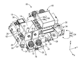
- FIG. 1 is an overall perspective view showing a circuit configuration according to the first embodiment of the present disclosure.
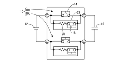
- FIG. 2 is a diagram schematically showing an electrical configuration in the path from the battery to the load.
- FIG. 3 is an exploded perspective view of the circuit configuration shown in FIG.
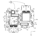
- FIG. 4 is a plan view of the circuit configuration shown in FIG.
- FIG. 5 is a perspective view of the fastening member shown in FIG.
- FIG. 6 is a view in which the fastening member shown in FIG. 5 is cut in the horizontal direction.
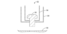
- FIG. 7A is a cross-sectional view showing a modified example of the fastening member shown in FIG. 1, and is a view showing before fastening.
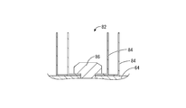
- FIG. 7B is a cross-sectional view showing a modified example of the fastening member shown in FIG.
- FIG. 8 is an overall perspective view showing the circuit configuration according to the second embodiment of the present disclosure, and is a diagram corresponding to FIG.
- FIG. 9 is a diagram showing a part of an overall perspective view showing the circuit configuration according to the third embodiment of the present disclosure.
- the circuit configuration of the present disclosure is (1) A circuit configuration including a heat-generating component that generates heat by energization, an energizing member connected to a connection portion of the heat-generating component, and a fastening member for fastening the energizing member, and the fastening member has heat-dissipating fins.
- the body is
- the fastening member used for fastening the energizing member directly connected to the connecting portion that is the heat generating portion of the heat generating component has a heat radiating fin. Therefore, as compared with the conventional structure in which the distance between the heat generating component and the heat radiating portion is large, the heat transferred to the energizing member can be quickly radiated through the heat radiating fin of the fastening member in the vicinity of the heat generating component. Moreover, since the fastening member for fastening the energizing member has heat radiation fins, by improving the fastening member that was originally required, the number of parts does not increase and the structure of the circuit structure is not complicated. , An efficient heat dissipation structure can be constructed.
- the heat-generating parts include parts that generate heat when energized, such as relays and fuses.
- the heat radiating fin any shape can be adopted as long as it is provided on the fastening member, and one provided integrally with the fastening member or one attached to the fastening member so as not to be detached. including.
- the fastening member any well-known fastening member can be adopted as long as it can be used for fastening the energizing member, and bolts, rivets and the like can be advantageously adopted.
- the energizing member is connected to the connecting portion of the heat generating component, the heat of the heat generating component is advantageously transferred, but the energizing member connected to the connecting portion of the heat generating component can be energized.
- Any member may be used, and includes those used for energizing between the connecting portion of the heat generating component and the other member, and those used only for heat dissipation without being connected to the other member.
- the fastening member includes a bolt and a fitting hole for a fastening tool is provided in the central portion of the head of the bolt.
- the outer peripheral portion of the head of the bolt is not limited to the fitting shape with the fastening tool.
- the heat radiation fin is integrally formed with the fastening member. This is because the fastening member having the heat radiating fins can be easily handled and the workability can be improved.
- the heat radiation fin formed separately from the fastening member is assembled to the fastening member so as not to be detached, and the heat radiation fin is fastened by fastening the fastening member.
- the heat radiation fins formed separately are assembled to the fastening member so as not to be detached, workability in the fastening work is also improved. Further, since the heat radiation fins can be fixed to the fastening member by fastening the fastening member, the stability of the heat radiation fin in the finished product is also ensured.
- the fastening member fastens the energizing member to the connecting portion of the heat generating component. Since the fastening member is used for fastening the energizing component to the connection portion of the heat generating component, the heat radiating fin can be arranged in the nearest vicinity of the heat generating portion of the heat generating component, and the heat radiating of the heat generating component can be realized more efficiently. Because.
- (6) Further includes a case for accommodating the heat generating component, the energizing member, and the fastening member having the heat radiating fin, and the case has a plurality of slit-shaped ventilation holes in a wall portion facing the heat radiating fin. It is preferable that it is provided.
- the heat of the heat-generating component transferred from the heat-dissipating fins can be further transferred to the outside of the case through the ventilation holes.
- heat dissipation of heat-generating parts using air convection can be efficiently realized.
- the ventilation holes are slit-shaped, it is possible to ensure waterproofness using surface tension while ensuring ventilation.
- the wall portion facing the heat radiating fin includes any of the wall portions arranged on the side, above, and further below the heat radiating fin.
- the circuit configuration 10 is mounted on a vehicle (not shown) such as an electric vehicle or a hybrid vehicle, for example.
- the circuit configuration 10 is used to connect the traveling battery to the vehicle side load 16 via the main relay 14, which is a heat generating component.
- the traveling battery is a battery 12, and is used as a battery for supplying electric power to a motor (not shown) for traveling a vehicle.
- the circuit configuration 10 can be arranged in any direction, but the Z direction shown in FIG. 1 will be described as upward, the Y direction as the width direction, and the X direction as the front. Further, for a plurality of the same members, a reference numeral may be added to only a part of the members, and the reference numeral may be omitted for the other members.
- the circuit configuration 10 includes a circuit configuration 10a provided on the positive electrode side and a circuit configuration 10b provided on the negative electrode side.
- the positive electrode side of the battery 12 is connected to the input side of the circuit configuration 10a, and the negative electrode side of the battery 12 is connected to the input side of the circuit configuration 10b.
- the positive electrode side of the vehicle side load 16 is connected to the output side of the circuit configuration 10a, and the negative electrode side of the vehicle side load 16 is connected to the output side of the circuit configuration 10b.
- a main relay 14 for connecting the battery 12 to the vehicle side load 16 is connected between the input side and the output side of the circuit structure 10a and the circuit structure 10b, respectively.
- the main relay 14 is connected to a precharge circuit 22 in which the precharge relay 18 and the precharge resistor 20 are connected in series so as to bypass the main relay 14, respectively.
- the precharge resistor 20 is connected to the input side of the precharge relay 18.
- both the main relay 14 and the precharge relay 18 are relays that move the contact portion to switch the contact portion ON / OFF while the exciting coil is energized, and ON / OFF control is performed by a control circuit (not shown). There is.
- the circuit structure 10a and the circuit structure 10b have substantially the same structure.
- the battery 12 has a high output voltage, for example, 100V to 400V, by connecting a plurality of rechargeable secondary batteries in series. It is also possible to increase the current capacity by connecting a plurality of secondary batteries in parallel.
- a lithium ion secondary battery, a lithium polymer secondary battery, a nickel hydrogen battery, or the like can be used.
- a capacitor such as an electric double layer capacitor (EDLC) can be used instead of or in addition to the secondary battery.
- the secondary battery also includes a capacitor.
- the vehicle-side load 16 includes, for example, a large-capacity capacitor having a capacitance of 200 ⁇ F to 5000 ⁇ F.
- a precharge circuit 22 is provided in order to prevent adverse effects due to the charge current.
- the precharge circuit 22 is provided in parallel with the main relay 14.
- the precharge circuit 22 connects a precharge resistor 20 in series with the precharge relay 18 in order to limit the charge current of the capacitor of the vehicle side load 16.
- the precharge resistor 20 limits the charging current of the capacitor of the vehicle side load 16 to a small value in a state where the precharge relay 18 and the main relay 14 are switched to ON.
- the circuit configuration 10 includes a lower case 24a located below and an upper case 24b located above when mounted on a vehicle, and the housing case 24 is provided by the lower case 24a and the upper case 24b. Is configured. In the state where the lower case 24a and the upper case 24b are assembled, various bus bars for connecting the battery 12, the vehicle side load 16, the main relay 14, and the precharge circuit 22 are housed inside the lower case 24a and the upper case 24b.
- the lower case 24a is formed by injection molding an insulating synthetic resin into a predetermined shape.
- the synthetic resin constituting the lower case 24a may contain a filler such as glass fiber.
- the lower case 24a has a substantially rectangular box shape that opens upward as a whole. As shown in FIGS. 3 and 4, engaging portions 26 projecting upward are provided at 4 to 6 locations separated from each other in the circumferential direction of the four peripheral edges of the lower case 24a.
- the upper case 24b is formed by injection molding an insulating synthetic resin into a predetermined shape.
- the synthetic resin constituting the upper case 24b may contain a filler such as glass fiber.
- the upper case 24b has a substantially box-shaped shape that opens downward, in which a peripheral wall 30 projecting downward is formed on the outer peripheral edge of an upper wall 28 having a substantially horizontally long rectangular flat plate shape. have.
- notch-shaped engaged portions are provided on the peripheral walls 30 on the four sides of the upper case 24b at positions corresponding to the engaging portions 26 of the lower case 24a, respectively. ..
- the circuit configuration 10 of the present disclosure is illustrated at three locations separated in the width direction (Y direction) of the upper wall 28 of the upper case 24b on the front side and the rear side (lower side and upper side in FIG. 4).
- a bolt fastening portion 34 is provided for fixing the vehicle at a predetermined position.
- a circuit configuration 10a provided on the positive electrode side is provided on one side (left side in FIG. 4) of the circuit configuration 10 in the width direction (Y direction).
- a circuit configuration 10b provided on the negative electrode side is provided on the other side (right side in FIG. 4) of the circuit configuration 10 in the width direction (Y direction).
- the circuit structure 10a will be described as an example here.
- a precharge relay is mounted on the upper surface of the upper wall 28 of the upper case 24b on which the circuit configuration 10a is formed from the rear side (upper side in FIG. 4).
- the portion 36, the precharge resistor mounting portion 38, and the main relay mounting portion 40 are formed so as to open upward.
- the precharge relay 18, the precharge resistor 20, and the main relay 14 are mounted on the precharge relay mounting portion 36, the precharge resistance mounting portion 38, and the main relay mounting portion 40.
- Two bolt fastening portions 42 are provided on one side (right side in FIG. 4) at positions facing the width direction (Y direction) on the peripheral edge portion of the main relay mounting portion 40, and the other side (in FIG. 4).
- FIG. 3 the front side (diagonally lower right side in FIG. 3) on the upper surface of the upper wall 28 of the upper case 24b on which the circuit configuration 10a is formed is in the width direction (Y direction).
- a pair of bus bar mounting portions 44a and 44b for the main relay which are rectangular in a plan view and are separated from each other and extend in the length direction (X direction), are provided.
- a main relay bus bar fixing portion 48 At the front ends of the pair of main relay bus bar mounting portions 44a and 44b, a main relay bus bar fixing portion 48 in which an annular nut 46 is housed is provided.
- the main relay 14 which is a heat generating component, is a so-called mechanical type having a contact portion and a coil portion (not shown) inside the main relay 14.
- the first power terminal 50 and the second power terminal 52 constituting the connection portion are provided side by side in the width direction (Y direction).
- Screw holes 54 are formed in the first power terminal 50 and the second power terminal 52, respectively.
- leg portions 56 having a substantially rectangular flat plate shape when viewed from above are projected outward at three locations at the lower end of the main relay 14.
- connector accommodating portions 62 projecting outward in the width direction (Y direction) are provided at the four corners of the lower end portion of the main relay 14 where the leg portions 56 are not provided.
- ⁇ Positive bus bar 64 and negative electrode bus bar 66> As shown in FIGS. 1, 3 and 4, a positive electrode bus bar 64 constituting an energizing member is connected to the main relay 14 provided in the circuit configuration 10a, and the main relay provided in the circuit configuration 10b is connected. A negative electrode bus bar 66 constituting an energizing member is connected to 14.
- the positive electrode bus bar 64 and the negative electrode bus bar 66 are formed by pressing a metal plate material into a predetermined shape.
- a metal having high thermal conductivity and low electrical resistance such as copper, copper alloy, aluminum, and aluminum alloy can be appropriately selected.
- the positive electrode bus bar 64 of the circuit structure 10a will be described as an example.
- Both the main relay input side bus bar 64a and the main relay output side bus bar 64b constituting the positive electrode bus bar 64 are bent in an L shape, and one end of the main relay 14 side extends upward to form the main relay. It is formed so as to be parallel to the front surface of 14.
- One end on the main relay 14 side is fastened to the first power terminal 50 and the second power terminal 52 by using a fastening member 76 described later, respectively, and is electrically connected to the first power terminal connection part 68 and the second power. It is a terminal connection portion 70.
- the other end of the main relay input side bus bar 64a and the main relay output side bus bar 64b extends forward in the length direction (X direction), and each is a battery connection portion connected to the positive electrode side of the battery 12. 72 and a vehicle-side load connecting portion 74 connected to the positive electrode side of the vehicle-side load 16 are formed.
- the fastening member 76 includes bolts 78. That is, the fastening member 76 has a hexagonal columnar head 78A forming the bolt 78 on the tip end side, and a cylindrical screw portion 78B forming the bolt 78 on the base end side. In the central portion of the tip of the head 78A of the bolt 78, a fitting hole 80 having a hexagonal cross-sectional shape for a hexagon wrench, which is a fastening tool (not shown), is opened outward and in the longitudinal direction of the head 78A. It is provided over almost the entire length.
- FIG. 6 shows the head 78A of the bolt 78 as a virtual line.
- the fastening member 76 includes an annular flange-shaped portion 76A protruding from the base end portion of the head 78A of the bolt 78 in the direction perpendicular to the axis, and a tip portion of the head 78A of the bolt 78 from the flange-shaped portion 76A. It has a heat radiating fin 76B provided up to a position that does not reach the position.
- the heat radiating fins 76B have a grid shape when viewed from the axial direction, and have a cylindrical shape as a whole.
- the heat radiation fin 76B is integrally formed with the fastening member 76.
- the heat radiation fins 76B are all made of metal.
- the metal constituting the heat radiating fin 76B a metal having high thermal conductivity and low electrical resistance such as copper, copper alloy, aluminum, and aluminum alloy can be appropriately selected.
- the heat radiating fin 76B is formed in a predetermined shape by a known method such as casting or cutting.
- the assembling method of the present embodiment will be briefly described below.
- the assembling method of the present embodiment will also be described by taking the circuit configuration 10a as an example as described above.
- various bus bars for connecting the battery 12, the vehicle-side load 16, the main relay 14, and the precharge circuit 22 are arranged in the lower case 24a.
- the upper case 24b is attached from above so as to cover the lower case 24a.
- the engaging portion 26 of the lower case 24a is engaged with the engaged portion of the upper case 24b and fixed to each other.
- the leg 56 of the main relay 14 is placed on the bolt fastening portion 42 provided on the peripheral edge of the main relay mounting portion 40 of the upper case 24b, and the leg 56 is fixed to the bolt fastening portion 42. ..
- the battery connection portion 72 of the main relay input side bus bar 64a and the vehicle side load connection portion 74 of the main relay output side bus bar 64b are mounted on the main relay bus bar mounting portions 44a and 44b, respectively.
- the first power terminal connection portion 68 of the main relay input side bus bar 64a and the second power terminal connection portion 70 of the main relay output side bus bar 64b are connected to the first power terminal 50 and the second power terminal of the main relay 14, respectively.
- the screw portions 78B of the fastening member 76 are inserted through the bolt insertion holes formed in the first power terminal connection portion 68 and the second power terminal connection portion 70, respectively, so that the first power terminal 50 and the second power terminal 50 and the second power terminal are second. It is inserted into the screw hole 54 of the power terminal 52. Subsequently, a fastening tool such as a hexagon wrench (not shown) is inserted into the fitting hole 80 of the fastening member 76 and rotated, so that the fastening member 76 causes the first power terminal connection portion 68 and the second power terminal connection portion 70, respectively. Bolts are fastened to the first power terminal 50 and the second power terminal 52.
- the battery connecting portion 72 of the main relay input side bus bar 64a and the vehicle side load connecting portion 74 of the main relay output side bus bar 64b are bolted to the main relay bus bar fixing portion 48 using bolts 58, respectively.
- the precharge relay 18 and the precharge resistor 20 are attached to the precharge relay mounting portion 36 and the precharge resistor mounting portion 38 of the upper case 24b to complete the circuit configuration 10 of the present embodiment.
- the circuit structure 10 can be fixed to a predetermined position of a vehicle (not shown) by using bolt fastening portions 34 provided at six positions of the upper case 24b, for example.
- the first power terminal 50 and the second power terminal 52 constituting the connection portion serving as the heat generating portion of the main relay 14 which is a heat generating component are connected to each other.
- the main relay input side bus bar 64a and the main relay output side bus bar 64b are directly connected by the fastening member 76.
- the fastening member 76 has metal radiating fins 76B having good thermal conductivity. Therefore, heat is dissipated in the fastening member 76 closest to the main relay 14, which is a heat generating component, as compared with the case where heat is dissipated at the end of the bus bar extending to the outside of the accommodation case 24 as in the conventional case.
- the fins 76B can be arranged so that heat can be quickly dissipated into the air. Moreover, since the fastening member 76 of the present disclosure is an improvement of the fastening member that was originally required, an efficient heat dissipation structure can be achieved without increasing the number of parts or complicating the structure of the circuit structure. Can be built.
- the fastening member 76 is configured to include the bolt 78 and the fitting hole 80 for the fastening tool is provided in the central portion of the head 78A of the bolt 78, the head of the bolt 78 is provided by the fastening tool. It is not necessary to grip the entire portion 78A. Therefore, since an extra space is not required around the head 78A of the bolt 78, it is possible to reduce the size of the circuit configuration 10 and improve the degree of freedom in designing the heat radiation fin 76B of the fastening member 76. Further, since the heat radiating fins 76B are integrally formed with the fastening member 76, the heat radiating fins 76B can be easily handled and workability can be improved.
- the heat radiating fins 76B are in a grid pattern when viewed from the axial direction, the surface area is increased, and a more efficient heat radiating structure is constructed.
- the heat radiation fin 76B may be any as long as it is provided on the fastening member 76.
- any shape such as a honeycomb shape when viewed from the axial direction or a rectangular flat plate shape extending in the direction perpendicular to the axis from a position separated in the circumferential direction on the outer peripheral surface of the head 78A of the bolt 78 can be adopted.
- any well-known fastening member can be adopted as long as it can be used for fastening the energizing member, and a rivet or the like can be advantageously adopted in addition to the bolt 78, and around the rivet. It may be provided with heat radiating fins.
- the main relay 14 has been described as an example of a heat generating component, but the present invention is not limited to this, and the heat generating component can be used for any component such as a fuse that generates heat when energized. is there.
- a positive electrode bus bar 64 used for connecting the first power terminal 50 and the second power terminal 52 constituting the connection portion of the main relay 14 which is a heat generating component and another member will be described as an example. However, it can also be applied to those that are not connected to other members and are simply used for heat dissipation.
- the heat radiation fin 76B is integrally formed with the fastening member 76, but the present invention is not limited to this.
- the heat radiation fins 84 and 84 are formed separately from the bolt 86, and the heat radiation fin 84 is formed with respect to the bolt 86. , 84 may be assembled so as not to be detached.
- the heat radiating fins 84 and 84 are both formed of a rectangular flat metal plate that is bent and formed in a U shape. Before fastening (see FIG.
- the heat radiation fins 84 and 84 are irremovably assembled to the bolt 86 by an engagement mechanism (not shown), and the heat radiation fin 84 is fastened to the positive electrode bus bar 64 by fastening the bolt 86 to the positive electrode bus bar 64. , 84 are fixed to the bolt 86 and the positive electrode bus bar 64 (see FIG. 7B).
- the heat radiating fin 84 having an arbitrary shape can be easily produced, so that the cost such as the mold cost can be reduced.
- the heat radiation fin 84 separately formed is assembled to the bolt 86 so as not to be detached, workability in the fastening work is also improved.
- the heat radiation fin 84 fixes the bolt 86 to the positive electrode bus bar 64 by fastening the bolt 86, the stability of the heat radiation fin 84 in the finished product is also ensured.
- the main relay input side bus bar 64a is provided with respect to the first power terminal 50 and the second power terminal 52 constituting the connection portion which is the heat generating portion of the main relay 14 which is a heat generating component.
- the main relay output side bus bar 64b were directly connected by the fastening member 76, but the present invention is not limited to this.
- the battery connecting portion 72 and the vehicle-side load connecting portion 74 may be bolted to the main relay bus bar fixing portion 48 by using a fastening member 76 together with a terminal or the like crimped to an external electric wire (not shown).
- the main relay 14 which is a heat generating component, has a heat dissipation component as compared with the case where heat is dissipated at the end of the bus bar pulled out to the outside of the storage case 24 as in the conventional case.
- the heat radiating fins 76B provided on the fastening member 76 can be arranged in the vicinity, so that heat can be quickly radiated into the air.
- the configuration is not limited to the first and second embodiments, and further includes a case 92 that covers the circuit configuration 88 shown in FIG. 8, such as the circuit configuration 90 of the third embodiment shown in FIG. You may be.
- the case 92 houses a main relay 14 which is a heat generating component, a positive electrode bus bar 64 which is an energizing member, a negative electrode bus bar 66, and a fastening member 76 having heat radiation fins 76B.
- the case 92 is provided with a plurality of (12 in this embodiment) slit-shaped ventilation holes 94 on the front side of the peripheral wall 92A and the front side of the upper wall 92B, which are wall portions facing the heat radiation fin 76B. ing.
- heat dissipation using air convection can be efficiently realized.
- the ventilation holes 94 are slit-shaped, it is possible to ensure waterproofness using surface tension while ensuring ventilation.
- the ventilation holes 94 are provided on the front side of the peripheral wall 92A of the case 92 and the front side of the upper wall 92B, but the present invention is not limited to this, and the width direction (Y direction) of the peripheral wall 92A of the case 92 is not limited to this. ) May be provided on both sides or the like.
- Circuit configuration (Embodiment 1) 10a Circuit configuration 10b Circuit configuration 12 Battery 14 Main relay (heat generating component) 16 Vehicle side load 18 Precharge relay 20 Precharge resistance 22 Precharge circuit 24 Storage case 24a Lower case 24b Upper case 26 Engagement part 28 Upper wall 30 Peripheral wall 34 Bolt fastening part 36 Precharge relay mounting part 38 Precharge resistance mounting part 40 Main relay mounting part 42 Bolt fastening part 44a, b Main relay bus bar mounting part 46 Nut 48 Main relay bus bar fixing part 50 First power terminal (connection part) 52 Second power terminal (connection part) 54 Screw hole 56 Leg 58 Bolt 60 Bolt insertion hole 62 Connector housing 64 Positive electrode bus bar (energizing member) 64a Main relay input side bus bar (energizing member) 64b Main relay output side bus bar (energized member) 66 Negative electrode bus bar (energized member) 68 First power terminal connection 70 Second power terminal connection 72 Battery connection 74 Vehicle side load connection 76 Fastening member 76A Flange-shaped part 76B Heat dissipation fin 78
Landscapes
- Engineering & Computer Science (AREA)
- Architecture (AREA)
- Civil Engineering (AREA)
- Structural Engineering (AREA)
- Physics & Mathematics (AREA)
- Thermal Sciences (AREA)
- Microelectronics & Electronic Packaging (AREA)
- Cooling Or The Like Of Electrical Apparatus (AREA)
- Connection Or Junction Boxes (AREA)
Abstract
より効率よく発熱部品の放熱を実現できる新規な構造の回路構成体を提供する。 通電により発熱する発熱部品を構成するメインリレー14と、発熱部品を構成するメインリレー14の接続部である第一電力端子50,第二電力端子52に接続される通電部材を構成するメインリレー入力側バスバー64a,メインリレー出力側バスバー64bと、メインリレー入力側バスバー64a,メインリレー出力側バスバー64bに締結される締結部材76とを含み、締結部材76が放熱フィン76Bを有している回路構成体10である。
Description
本開示は、発熱部品を有する回路構成体に関する。
従来から、通電により発熱するリレーやヒューズ等の発熱部品を備えた回路構成体においては、発熱部品の熱を放熱するための放熱構造が設けられる場合がある。例えば、特許文献1には、ケース内に収容されたリレーの接続部とケース外に配置されたバッテリーの接続端子とを接続するバスバーの中間部分を利用して、リレーの放熱を行う構造が提案されている。具体的には、リレーを収容するケース外に延出されたバスバーの中間部を絶縁性放熱シートを介してシャーシや電源装置全体を収容する筐体等に当接させることで、リレーで発生した熱をシャーシや筐体に熱伝導して放熱する構造が開示されている。
ところが、特許文献1の構造では、リレーとバッテリーを接続する通電部を構成するバスバーの中間部に放熱構造が設けられていることから、リレーの接続部と放熱部分との距離が大きくなることが避けられない。そのため、リレーでの発熱を効率よく放熱できていないという問題を内在していた。
そこで、より効率よく発熱部品の放熱を実現できる新規な構造の回路構成体を提供することを目的とする。
本開示の回路構成体は、通電により発熱する発熱部品と、前記発熱部品の接続部に接続される通電部材と、前記通電部材に締結される締結部材とを含み、前記締結部材が放熱フィンを有している回路構成体である。
本開示によれば、より効率よく発熱部品の放熱を実現する回路構成体を提供することができる。
<本開示の実施形態の説明>
最初に、本開示の実施態様を列記して説明する。
本開示の回路構成体は、
(1)通電により発熱する発熱部品と、前記発熱部品の接続部に接続される通電部材と、前記通電部材を締結する締結部材とを含み、前記締結部材が放熱フィンを有している回路構成体である。
最初に、本開示の実施態様を列記して説明する。
本開示の回路構成体は、
(1)通電により発熱する発熱部品と、前記発熱部品の接続部に接続される通電部材と、前記通電部材を締結する締結部材とを含み、前記締結部材が放熱フィンを有している回路構成体である。
本開示の回路構成体によれば、発熱部品の発熱部位となる接続部に直接接続される通電部材の締結用に用いられる締結部材が放熱フィンを有している。そのため、発熱部品と放熱部分との距離が大きくなる従来構造に比して、発熱部品の近傍で、通電部材に伝熱された熱を締結部材の放熱フィンを通じて速やかに放熱することができる。しかも、通電部材を締結する締結部材が放熱フィンを有していることから、もともと必要であった締結部材を改良することにより、部品点数の増大や回路構造体の構造の複雑化を伴うことなく、効率的な放熱構造を構築することができる。
なお、発熱部品には、リレーやヒューズ等の通電により発熱する部品が含まれる。放熱フィンについては、締結部材に設けられているものであれば、任意の形状が採用可能であり、締結部材に対して一体的に設けられたものや、締結部材に離脱不能に組み付けられたものを含む。締結部材としては、通電部材の締結用に用いられ得るものであれば、周知のいずれの締結部材も採用可能であり、ボルトやリベット等が有利に採用され得る。加えて、通電部材は、発熱部品の接続部に接続されているため、発熱部品の熱が有利に伝熱されるものであるが、発熱部品の接続部に接続された通電部材は、通電可能な部材であればよく、発熱部品の接続部と他部材との間の通電用として用いられるものの他、他部材に接続されず単に放熱用に用いられるものも含まれる。
(2)前記締結部材がボルトを含んで構成されており、前記ボルトの頭部の中央部分に締結用工具の嵌合穴が設けられていることが好ましい。これにより、ボルトの頭部の外周部分が締結用工具との嵌合形状に制限されることがない。その結果、放熱フィンの表面積を拡大したり、放熱フィンの形状を周囲のスペースの形状に対応した任意の形状とすることも可能となり、放熱フィンの設計自由度の向上を図ることができる。
(3)前記放熱フィンが前記締結部材に一体形成されていることが好ましい。放熱フィンを有する締結部材の取り扱いが容易となり、作業性の向上を図ることができるからである。
(4)上記(1)または(2)において、前記締結部材と別体形成された前記放熱フィンが、前記締結部材に対して離脱不能に組み付けられており、前記締結部材の締結により前記放熱フィンが前記締結部材に固定されることが好ましい。放熱フィンを予め締結部材とは別体として形成できることから、放熱フィンを締結部材に一体形成する場合に比して、任意の形状の放熱フィンを簡単に作成でき、型費用等のコストの低減を図ることができる。しかも、別体形成された放熱フィンは締結部材に対して離脱不能に組み付けられていることから、締結作業における作業性の向上も図られている。さらに、締結部材の締結により放熱フィンが締結部材に対して固定することができることから、完成品における放熱フィンの安定性も確保されている。
(5)前記締結部材が、前記通電部材を前記発熱部品の前記接続部に締結していることが好ましい。締結部材が発熱部品の接続部への通電部品の締結用に用いられることから、発熱部品の発熱部位の最も近傍に放熱フィンを配設することができ、一層効率よく発熱部品の放熱を実現できるからである。
(6)前記発熱部品と前記通電部材と前記放熱フィンを有する前記締結部材を収容するケースをさらに含み、前記ケースには、前記放熱フィンに対向する壁部において、複数のスリット状の通気孔が設けられていることが好ましい。放熱フィンから伝熱される発熱部品の熱を通気孔を通じてさらにケース外部に伝熱させることができる。また空気の対流を利用した発熱部品の放熱を効率よく実現できる。しかも、通気孔がスリット状とされていることから、通気性を確保しつつ表面張力を利用した防水性も担保し得る。なお、放熱フィンに対向する壁部とは、放熱フィンの側方や上方、更には下方に配置された壁部をいずれも含むものである。
<本開示の実施形態の詳細>
本開示の回路構成体の具体例を、以下に図面を参照しつつ説明する。なお、本開示は、これらの例示に限定されるものではなく、特許請求の範囲によって示され、特許請求の範囲と均等の意味および範囲内でのすべての変更が含まれることが意図される。
本開示の回路構成体の具体例を、以下に図面を参照しつつ説明する。なお、本開示は、これらの例示に限定されるものではなく、特許請求の範囲によって示され、特許請求の範囲と均等の意味および範囲内でのすべての変更が含まれることが意図される。
<実施形態1>
以下、本開示の実施形態1について、図1から図6を参照しつつ説明する。回路構成体10は、例えば、電気自動車やハイブリッド自動車等の車両(図示せず)に搭載されている。回路構成体10は、例えば図2に示すように、走行用バッテリーを発熱部品であるメインリレー14を介して車両側負荷16に接続するために用いられる。ここで、走行用バッテリーとはバッテリー12のことであり、車両を走行させるモータ(図示せず)に電力を供給させるバッテリーとして利用される。なお、回路構成体10は、任意の向きで配置することができるが、以下では、図1に示すZ方向を上方、Y方向を幅方向、X方向を前方として説明する。さらに、複数の同一部材については、一部の部材にのみ符号を付し、他の部材については符号を省略する場合がある。
以下、本開示の実施形態1について、図1から図6を参照しつつ説明する。回路構成体10は、例えば、電気自動車やハイブリッド自動車等の車両(図示せず)に搭載されている。回路構成体10は、例えば図2に示すように、走行用バッテリーを発熱部品であるメインリレー14を介して車両側負荷16に接続するために用いられる。ここで、走行用バッテリーとはバッテリー12のことであり、車両を走行させるモータ(図示せず)に電力を供給させるバッテリーとして利用される。なお、回路構成体10は、任意の向きで配置することができるが、以下では、図1に示すZ方向を上方、Y方向を幅方向、X方向を前方として説明する。さらに、複数の同一部材については、一部の部材にのみ符号を付し、他の部材については符号を省略する場合がある。
<回路構成体10の概要>
回路構成体10は、図2に示すように、正極側に設けられた回路構成体10aと負極側に設けられた回路構成体10bを備えている。回路構成体10aの入力側には、バッテリー12の正極側が接続されており、回路構成体10bの入力側には、バッテリー12の負極側が接続されている。回路構成体10aの出力側には、車両側負荷16の正極側が接続されており、回路構成体10bの出力側には、車両側負荷16の負極側が接続されている。回路構成体10aと回路構成体10bの入力側と出力側の間にはそれぞれ、バッテリー12を車両側負荷16に接続するメインリレー14が接続されている。加えて、メインリレー14にはそれぞれ、プリチャージリレー18およびプリチャージ抵抗20がメインリレー14をバイパスするように直列に接続されたプリチャージ回路22が接続されている。なお、本開示の実施形態1では、図2に示すように、プリチャージ抵抗20は、プリチャージリレー18の入力側に接続されている。さらに、メインリレー14とプリチャージリレー18はいずれも、励磁コイルの通電状態で接点部を移動させて接点部をON/OFFに切り換えるリレーであり、図示しない制御回路によりON/OFF制御がなされている。以上述べてきたように、回路構成体10aと回路構成体10bは略同一構造とされている。
回路構成体10は、図2に示すように、正極側に設けられた回路構成体10aと負極側に設けられた回路構成体10bを備えている。回路構成体10aの入力側には、バッテリー12の正極側が接続されており、回路構成体10bの入力側には、バッテリー12の負極側が接続されている。回路構成体10aの出力側には、車両側負荷16の正極側が接続されており、回路構成体10bの出力側には、車両側負荷16の負極側が接続されている。回路構成体10aと回路構成体10bの入力側と出力側の間にはそれぞれ、バッテリー12を車両側負荷16に接続するメインリレー14が接続されている。加えて、メインリレー14にはそれぞれ、プリチャージリレー18およびプリチャージ抵抗20がメインリレー14をバイパスするように直列に接続されたプリチャージ回路22が接続されている。なお、本開示の実施形態1では、図2に示すように、プリチャージ抵抗20は、プリチャージリレー18の入力側に接続されている。さらに、メインリレー14とプリチャージリレー18はいずれも、励磁コイルの通電状態で接点部を移動させて接点部をON/OFFに切り換えるリレーであり、図示しない制御回路によりON/OFF制御がなされている。以上述べてきたように、回路構成体10aと回路構成体10bは略同一構造とされている。
<バッテリー12>
バッテリー12は、充電可能な複数の二次電池を直列に接続して出力電圧を高く、例えば100V~400Vとしている。また、複数の二次電池を並列に接続して電流容量を大きくすることもできる。この二次電池には、リチウムイオン二次電池、リチウムポリマー二次電池、ニッケル水素電池などが使用できる。また、二次電池に代えて、あるいはこれに加えて、電気二重層キャパシタ(EDLC)等のキャパシタを利用することもできる。本明細書において二次電池にはキャパシタも含む。
バッテリー12は、充電可能な複数の二次電池を直列に接続して出力電圧を高く、例えば100V~400Vとしている。また、複数の二次電池を並列に接続して電流容量を大きくすることもできる。この二次電池には、リチウムイオン二次電池、リチウムポリマー二次電池、ニッケル水素電池などが使用できる。また、二次電池に代えて、あるいはこれに加えて、電気二重層キャパシタ(EDLC)等のキャパシタを利用することもできる。本明細書において二次電池にはキャパシタも含む。
<車両側負荷16>
車両側負荷16は、例えば、静電容量を200μF~5000μFとする大容量のコンデンサを含んでいる。このコンデンサが完全に放電された状態でメインリレー14がON状態に切り換えられると、コンデンサを充電するために瞬間的に極めて大きなチャージ電流が流れる。極めて大きなチャージ電流はメインリレー14の接点部を損傷させる原因となることから、チャージ電流による弊害を防止するために、プリチャージ回路22を設けている。本開示の実施形態1では、図2に示すように、メインリレー14と並列にプリチャージ回路22を設けている。プリチャージ回路22は、車両側負荷16のコンデンサのチャージ電流を制限するために、プリチャージリレー18と直列にプリチャージ抵抗20を接続している。プリチャージ抵抗20は、プリチャージリレー18およびメインリレー14をONに切り換えた状態で、車両側負荷16のコンデンサの充電電流を小さく制限する。
車両側負荷16は、例えば、静電容量を200μF~5000μFとする大容量のコンデンサを含んでいる。このコンデンサが完全に放電された状態でメインリレー14がON状態に切り換えられると、コンデンサを充電するために瞬間的に極めて大きなチャージ電流が流れる。極めて大きなチャージ電流はメインリレー14の接点部を損傷させる原因となることから、チャージ電流による弊害を防止するために、プリチャージ回路22を設けている。本開示の実施形態1では、図2に示すように、メインリレー14と並列にプリチャージ回路22を設けている。プリチャージ回路22は、車両側負荷16のコンデンサのチャージ電流を制限するために、プリチャージリレー18と直列にプリチャージ抵抗20を接続している。プリチャージ抵抗20は、プリチャージリレー18およびメインリレー14をONに切り換えた状態で、車両側負荷16のコンデンサの充電電流を小さく制限する。
<回路構成体10>
回路構成体10は、例えば図1および図3に示すように、車両搭載時において下方に位置するロアケース24aと上方に位置するアッパケース24bを備えており、ロアケース24aとアッパケース24bによって収容ケース24が構成されている。ロアケース24aとアッパケース24bが組み付けられた状態において、その内部にはバッテリー12や車両側負荷16とメインリレー14やプリチャージ回路22を接続する各種バスバーが収容されている。
回路構成体10は、例えば図1および図3に示すように、車両搭載時において下方に位置するロアケース24aと上方に位置するアッパケース24bを備えており、ロアケース24aとアッパケース24bによって収容ケース24が構成されている。ロアケース24aとアッパケース24bが組み付けられた状態において、その内部にはバッテリー12や車両側負荷16とメインリレー14やプリチャージ回路22を接続する各種バスバーが収容されている。
<ロアケース24a>
ロアケース24aは、絶縁性の合成樹脂を所定の形状に射出成型してなる。ロアケース24aを構成する合成樹脂は、ガラスファイバー等のフィラーを含んでいてもよい。ロアケース24aは、全体として上方に向かって開口する略矩形箱体形状をなしている。図3および図4に示すように、ロアケース24aの周縁部の4つの辺の周方向に離隔する4~6箇所にはそれぞれ上方に向かって突出する係合部26が設けられている。
ロアケース24aは、絶縁性の合成樹脂を所定の形状に射出成型してなる。ロアケース24aを構成する合成樹脂は、ガラスファイバー等のフィラーを含んでいてもよい。ロアケース24aは、全体として上方に向かって開口する略矩形箱体形状をなしている。図3および図4に示すように、ロアケース24aの周縁部の4つの辺の周方向に離隔する4~6箇所にはそれぞれ上方に向かって突出する係合部26が設けられている。
<アッパケース24b>
アッパケース24bは、絶縁性の合成樹脂を所定の形状に射出成型してなる。アッパケース24bを構成する合成樹脂は、ガラスファイバー等のフィラーを含んでいてもよい。アッパケース24bは、例えば図3に示すように、略横長矩形の平板状とされた上壁28の外周縁部に、下方に突出する周壁30が形成された、下方に開口する略箱体形状を有している。図3および図4に示すように、アッパケース24bの4つの辺の周壁30にはそれぞれロアケース24aの係合部26に対応する位置に、図示しない切欠状の被係合部が設けられている。アッパケース24bの上壁28の前方側および後方側(図4中、下方側および上方側)の幅方向(Y方向)に離隔する3箇所にはそれぞれ、本開示の回路構成体10を例えば図示しない車両の所定箇所に固定するためのボルト締結部34が設けられている。
アッパケース24bは、絶縁性の合成樹脂を所定の形状に射出成型してなる。アッパケース24bを構成する合成樹脂は、ガラスファイバー等のフィラーを含んでいてもよい。アッパケース24bは、例えば図3に示すように、略横長矩形の平板状とされた上壁28の外周縁部に、下方に突出する周壁30が形成された、下方に開口する略箱体形状を有している。図3および図4に示すように、アッパケース24bの4つの辺の周壁30にはそれぞれロアケース24aの係合部26に対応する位置に、図示しない切欠状の被係合部が設けられている。アッパケース24bの上壁28の前方側および後方側(図4中、下方側および上方側)の幅方向(Y方向)に離隔する3箇所にはそれぞれ、本開示の回路構成体10を例えば図示しない車両の所定箇所に固定するためのボルト締結部34が設けられている。
図3および図4に示すように、回路構成体10の幅方向(Y方向)の一方側(図4中、左側)には、正極側に設けられた回路構成体10aが設けられており、回路構成体10の幅方向(Y方向)の他方側(図4中、右側)には、負極側に設けられた回路構成体10bが設けられている。上述のように、回路構成体10aと回路構成体10bは略同一構造とされていることから、ここでは、回路構成体10aを例にとって説明を行うことにする。
図1,図3および図4に示すように、回路構成体10aが形成されているアッパケース24bの上壁28の上面には、後方側(図4中、上方側)から、プリチャージリレー装着部36やプリチャージ抵抗装着部38やメインリレー装着部40が上方に向かって開口して形成されている。プリチャージリレー装着部36やプリチャージ抵抗装着部38やメインリレー装着部40に対して、プリチャージリレー18やプリチャージ抵抗20やメインリレー14が装着されている。メインリレー装着部40の周縁部における幅方向(Y方向)に対向する位置には、一方の側(図4中、右側)に2つのボルト締結部42が設けられ、他方の側(図4中、左側)に1つのボルト締結部42が設けられている。また、図3に示すように、回路構成体10aが形成されているアッパケース24bの上壁28の上面における前方側(図3中、右斜め下方側)には、幅方向(Y方向)に離隔して長さ方向(X方向)に延びる平面視で矩形状の一対のメインリレー用バスバー載置部44a,44bが設けられている。一対のメインリレー用バスバー載置部44a,44bの前端部には、円環状のナット46が収容されたメインリレー用バスバー固定部48が設けられている。
<メインリレー14>
発熱部品であるメインリレー14は、その内部に図示しない接点部およびコイル部を有する、いわゆる機械式のものである。例えば図3に示すように、メインリレー14の前面には、接続部を構成する第一電力端子50と第二電力端子52が幅方向(Y方向)に並んで設けられている。第一電力端子50と第二電力端子52に電流を流すことにより、メインリレー14の接点部で熱が発生し、第一電力端子50および第二電力端子52に熱伝導されるようになっている。第一電力端子50および第二電力端子52にはそれぞれ、ねじ孔54が形成されている。図3および図4に示すように、メインリレー14の下端部の3箇所には、上方から見て略矩形平板状をなす脚部56が外方に向かって突設されている。脚部56にはボルト58が挿通されるボルト挿通孔60が貫設されている。また、メインリレー14の下端部の四隅のうち脚部56が設けられていない箇所には、幅方向(Y方向)外方に向かって突出するコネクタ収容部62が設けられている。このコネクタ収容部62に図示しない外部コネクタが装着されることにより、メインリレー14のON/OFFが切り換えられるようになっている。
発熱部品であるメインリレー14は、その内部に図示しない接点部およびコイル部を有する、いわゆる機械式のものである。例えば図3に示すように、メインリレー14の前面には、接続部を構成する第一電力端子50と第二電力端子52が幅方向(Y方向)に並んで設けられている。第一電力端子50と第二電力端子52に電流を流すことにより、メインリレー14の接点部で熱が発生し、第一電力端子50および第二電力端子52に熱伝導されるようになっている。第一電力端子50および第二電力端子52にはそれぞれ、ねじ孔54が形成されている。図3および図4に示すように、メインリレー14の下端部の3箇所には、上方から見て略矩形平板状をなす脚部56が外方に向かって突設されている。脚部56にはボルト58が挿通されるボルト挿通孔60が貫設されている。また、メインリレー14の下端部の四隅のうち脚部56が設けられていない箇所には、幅方向(Y方向)外方に向かって突出するコネクタ収容部62が設けられている。このコネクタ収容部62に図示しない外部コネクタが装着されることにより、メインリレー14のON/OFFが切り換えられるようになっている。
<正極バスバー64および負極バスバー66>
図1,図3および図4に示すように、回路構成体10aに設けられたメインリレー14には通電部材を構成する正極バスバー64が接続されており、回路構成体10bに設けられたメインリレー14には通電部材を構成する負極バスバー66が接続されている。なお、正極バスバー64および負極バスバー66は、金属板材を所定の形状にプレス加工してなる。正極バスバー64および負極バスバー66を構成する金属としては、銅、銅合金、アルミニウム、アルミニウム合金等の熱伝導性が高く、電気抵抗の低い金属を適宜に選択することができる。上述のように、回路構成体10aと回路構成体10bは略同一構造とされていることから、ここでは、回路構成体10aの正極バスバー64を例にとって説明を行うことにする。正極バスバー64を構成するメインリレー入力側バスバー64aとメインリレー出力側バスバー64bはいずれもL字状に屈曲形成されており、メインリレー14側の一端部が上方に向かって延び出して、メインリレー14の前面に平行になるように形成されている。メインリレー14側の一端部がそれぞれ、後述する締結部材76を用いて第一電力端子50,第二電力端子52に締結されて電気的に接続される第一電力端子接続部68,第二電力端子接続部70となっている。メインリレー入力側バスバー64aとメインリレー出力側バスバー64bの他方側の端部は長さ方向前方(X方向)に向かって延び出しており、それぞれ、バッテリー12の正極側に接続されるバッテリー接続部72と、車両側負荷16の正極側に接続される車両側負荷接続部74を形成している。
図1,図3および図4に示すように、回路構成体10aに設けられたメインリレー14には通電部材を構成する正極バスバー64が接続されており、回路構成体10bに設けられたメインリレー14には通電部材を構成する負極バスバー66が接続されている。なお、正極バスバー64および負極バスバー66は、金属板材を所定の形状にプレス加工してなる。正極バスバー64および負極バスバー66を構成する金属としては、銅、銅合金、アルミニウム、アルミニウム合金等の熱伝導性が高く、電気抵抗の低い金属を適宜に選択することができる。上述のように、回路構成体10aと回路構成体10bは略同一構造とされていることから、ここでは、回路構成体10aの正極バスバー64を例にとって説明を行うことにする。正極バスバー64を構成するメインリレー入力側バスバー64aとメインリレー出力側バスバー64bはいずれもL字状に屈曲形成されており、メインリレー14側の一端部が上方に向かって延び出して、メインリレー14の前面に平行になるように形成されている。メインリレー14側の一端部がそれぞれ、後述する締結部材76を用いて第一電力端子50,第二電力端子52に締結されて電気的に接続される第一電力端子接続部68,第二電力端子接続部70となっている。メインリレー入力側バスバー64aとメインリレー出力側バスバー64bの他方側の端部は長さ方向前方(X方向)に向かって延び出しており、それぞれ、バッテリー12の正極側に接続されるバッテリー接続部72と、車両側負荷16の正極側に接続される車両側負荷接続部74を形成している。
<締結部材76>
締結部材76は、図5および図6に示すように、ボルト78を含んで構成されている。すなわち、締結部材76は、先端部側にボルト78を構成する六角柱形状の頭部78Aを有し、基端部側にボルト78を構成する円柱形状のねじ部78Bを有している。ボルト78の頭部78Aの先端部の中央部分には、図示しない締結用工具である六角レンチ用の六角断面形状の嵌合穴80が外方に向かって開口しかつ頭部78Aの長手方向の略全長に亘って設けられている。なお、理解を容易とするため、図6では、ボルト78の頭部78Aを仮想線で記載している。加えて、締結部材76は、ボルト78の頭部78Aの基端部から軸直角方向に向かって突出する円環状のフランジ状部76Aと、フランジ状部76Aからボルト78の頭部78Aの先端部に到らない位置まで設けられた放熱フィン76Bと、を有している。放熱フィン76Bは、軸方向から見て格子状とされており、全体として円柱形状を有している。このように、本実施形態では、放熱フィン76Bが締結部材76に一体形成されている。放熱フィン76Bは何れも金属製とされている。放熱フィン76Bを構成する金属としては、銅、銅合金、アルミニウム、アルミニウム合金等の熱伝導性が高く、電気抵抗の低い金属を適宜に選択することができる。放熱フィン76Bは、鋳造、切削加工等、公知の手法により所定の形状に形成されている。
締結部材76は、図5および図6に示すように、ボルト78を含んで構成されている。すなわち、締結部材76は、先端部側にボルト78を構成する六角柱形状の頭部78Aを有し、基端部側にボルト78を構成する円柱形状のねじ部78Bを有している。ボルト78の頭部78Aの先端部の中央部分には、図示しない締結用工具である六角レンチ用の六角断面形状の嵌合穴80が外方に向かって開口しかつ頭部78Aの長手方向の略全長に亘って設けられている。なお、理解を容易とするため、図6では、ボルト78の頭部78Aを仮想線で記載している。加えて、締結部材76は、ボルト78の頭部78Aの基端部から軸直角方向に向かって突出する円環状のフランジ状部76Aと、フランジ状部76Aからボルト78の頭部78Aの先端部に到らない位置まで設けられた放熱フィン76Bと、を有している。放熱フィン76Bは、軸方向から見て格子状とされており、全体として円柱形状を有している。このように、本実施形態では、放熱フィン76Bが締結部材76に一体形成されている。放熱フィン76Bは何れも金属製とされている。放熱フィン76Bを構成する金属としては、銅、銅合金、アルミニウム、アルミニウム合金等の熱伝導性が高く、電気抵抗の低い金属を適宜に選択することができる。放熱フィン76Bは、鋳造、切削加工等、公知の手法により所定の形状に形成されている。
<本実施形態の組付方法>
本実施形態の組付方法について以下に簡単に説明する。本実施形態の組付方法についても、上述のように回路構成体10aを例にとって説明を行うことにする。はじめに、ロアケース24aに対して、バッテリー12や車両側負荷16とメインリレー14やプリチャージ回路22を接続する各種バスバーを配設する。このようなロアケース24aを覆蓋するようにアッパケース24bを上方から装着する。これにより、ロアケース24aの係合部26がアッパケース24bの被係合部に係合されて相互に固定される。次に、メインリレー14の脚部56を、アッパケース24bのメインリレー装着部40の周縁部に設けられたボルト締結部42に対して載置し、脚部56をボルト締結部42に固定する。続いて、メインリレー入力側バスバー64aのバッテリー接続部72とメインリレー出力側バスバー64bの車両側負荷接続部74をそれぞれ、メインリレー用バスバー載置部44a,44b上に載置する。この状態で、メインリレー入力側バスバー64aの第一電力端子接続部68とメインリレー出力側バスバー64bの第二電力端子接続部70をそれぞれ、メインリレー14の第一電力端子50と第二電力端子52にボルト締結する。より詳細には、締結部材76のねじ部78Bをそれぞれ、第一電力端子接続部68と第二電力端子接続部70に貫設されたボルト挿通孔を挿通して第一電力端子50と第二電力端子52のねじ孔54に挿入する。続いて、図示しない六角レンチ等の締結用工具を締結部材76の嵌合穴80に差し込んで回転することにより、締結部材76によって第一電力端子接続部68と第二電力端子接続部70がそれぞれ第一電力端子50と第二電力端子52にボルト締結されるようになっている。併せて、メインリレー入力側バスバー64aのバッテリー接続部72とメインリレー出力側バスバー64bの車両側負荷接続部74をそれぞれ、ボルト58を用いてメインリレー用バスバー固定部48に対してボルト締結する。最後に、アッパケース24bのプリチャージリレー装着部36やプリチャージ抵抗装着部38に対してプリチャージリレー18やプリチャージ抵抗20を装着して、本実施形態の回路構成体10が完成する。なお、この回路構成体10は、アッパケース24bの6箇所に設けられたボルト締結部34を用いて例えば図示しない車両の所定箇所に固定することができるようになっている。
本実施形態の組付方法について以下に簡単に説明する。本実施形態の組付方法についても、上述のように回路構成体10aを例にとって説明を行うことにする。はじめに、ロアケース24aに対して、バッテリー12や車両側負荷16とメインリレー14やプリチャージ回路22を接続する各種バスバーを配設する。このようなロアケース24aを覆蓋するようにアッパケース24bを上方から装着する。これにより、ロアケース24aの係合部26がアッパケース24bの被係合部に係合されて相互に固定される。次に、メインリレー14の脚部56を、アッパケース24bのメインリレー装着部40の周縁部に設けられたボルト締結部42に対して載置し、脚部56をボルト締結部42に固定する。続いて、メインリレー入力側バスバー64aのバッテリー接続部72とメインリレー出力側バスバー64bの車両側負荷接続部74をそれぞれ、メインリレー用バスバー載置部44a,44b上に載置する。この状態で、メインリレー入力側バスバー64aの第一電力端子接続部68とメインリレー出力側バスバー64bの第二電力端子接続部70をそれぞれ、メインリレー14の第一電力端子50と第二電力端子52にボルト締結する。より詳細には、締結部材76のねじ部78Bをそれぞれ、第一電力端子接続部68と第二電力端子接続部70に貫設されたボルト挿通孔を挿通して第一電力端子50と第二電力端子52のねじ孔54に挿入する。続いて、図示しない六角レンチ等の締結用工具を締結部材76の嵌合穴80に差し込んで回転することにより、締結部材76によって第一電力端子接続部68と第二電力端子接続部70がそれぞれ第一電力端子50と第二電力端子52にボルト締結されるようになっている。併せて、メインリレー入力側バスバー64aのバッテリー接続部72とメインリレー出力側バスバー64bの車両側負荷接続部74をそれぞれ、ボルト58を用いてメインリレー用バスバー固定部48に対してボルト締結する。最後に、アッパケース24bのプリチャージリレー装着部36やプリチャージ抵抗装着部38に対してプリチャージリレー18やプリチャージ抵抗20を装着して、本実施形態の回路構成体10が完成する。なお、この回路構成体10は、アッパケース24bの6箇所に設けられたボルト締結部34を用いて例えば図示しない車両の所定箇所に固定することができるようになっている。
このような構造とされた本開示の回路構成体10によれば、発熱部品であるメインリレー14の発熱部位となる接続部を構成する第一電力端子50と第二電力端子52に対して、メインリレー入力側バスバー64aとメインリレー出力側バスバー64bが締結部材76によって直接接続されている。しかも、締結部材76は熱伝導率の良い金属製の放熱フィン76Bを有している。それゆえ、従来の如き収容ケース24の外部に延び出したバスバーの端部で放熱を行っていた場合に比して、発熱部品であるメインリレー14の最も近傍に締結部材76に設けられた放熱フィン76Bを配設でき、空気中に速やかに放熱することができる。しかも、本開示の締結部材76は、もともと必要であった締結部材を改良したものであることから、部品点数の増大や回路構造体の構造の複雑化を伴うことなく、効率的な放熱構造を構築することができる。
また、締結部材76がボルト78を含んで構成されており、ボルト78の頭部78Aの中央部分に締結用工具の嵌合穴80が設けられていることから、締結用工具によってボルト78の頭部78A全体を把持する必要がない。それゆえ、ボルト78の頭部78Aの周囲に余分なスペースを必要としないことから、回路構成体10の小型化や締結部材76の放熱フィン76Bの設計自由度の向上を図ることができる。さらに、放熱フィン76Bが締結部材76に一体形成されていることから、放熱フィン76Bの取り扱いが容易であり、作業性の向上を図ることができる。加えて、放熱フィン76Bが軸方向から見て格子状とされていることから、表面積が大きくされており、一層効率的な放熱構造が構築されている。なお、放熱フィン76Bについては、締結部材76に設けられているものであればよい。例えば、軸方向から見てハニカム形状であったり、ボルト78の頭部78Aの外周面において周方向に離隔した位置から軸直角方向に延び出す矩形平板形状等の任意の形状が採用可能である。また、締結部材としては、通電部材の締結用に用いられ得るものであれば、周知のいずれの締結部材も採用可能であり、ボルト78以外にリベット等が有利に採用され得、リベットの周囲に放熱フィンを設けたものでもよい。
<他の実施形態>
本明細書に記載された技術は上記記述および図面によって説明した実施形態に限定されるものではなく、例えば次のような実施形態も本明細書に記載された技術の技術的範囲に含まれる。
本明細書に記載された技術は上記記述および図面によって説明した実施形態に限定されるものではなく、例えば次のような実施形態も本明細書に記載された技術の技術的範囲に含まれる。
(1)上記実施形態1では、発熱部品としてメインリレー14を例にとって説明を行ったが、これに限定されず、発熱部品として通電により発熱するヒューズ等の任意の部品に対しても採用可能である。また、通電部材として、発熱部品であるメインリレー14の接続部を構成する第一電力端子50,第二電力端子52と他部材との接続に用いられている正極バスバー64を例にとって説明を行ったが、他部材に接続されず単に放熱用に用いられるものにも適用可能である。
(2)上記実施形態1では、放熱フィン76Bが締結部材76に一体形成されていたが、これに限定されない。例えば、図7A,図7Bに示す実施形態1の締結部材76の変形例である締結部材82のように、放熱フィン84,84がボルト86と別体で形成されボルト86に対して放熱フィン84,84が離脱不能に組み付けられたものでもよい。放熱フィン84,84はいずれもU字状に屈曲形成された矩形平板状の金属板によって構成されている。締結前(図7A参照)には放熱フィン84,84がボルト86に対して図示しない係合機構により離脱不能に組み付けられており、ボルト86を正極バスバー64に対して締結することにより放熱フィン84,84がボルト86および正極バスバー64に対して固定されるようになっている(図7B参照)。これにより、放熱フィン76Bを締結部材76に一体形成する場合に比して、任意の形状の放熱フィン84を簡単に作成できることから、型費用等のコストの低減を図ることができる。また、別体形成された放熱フィン84はボルト86に対して離脱不能に組み付けられていることから、締結作業における作業性の向上も図られている。さらに、ボルト86の締結により放熱フィン84がボルト86を正極バスバー64に対して固定されることから、完成品における放熱フィン84の安定性も確保されている。
(3)本開示の回路構成体10では、発熱部品であるメインリレー14の発熱部位となる接続部を構成する第一電力端子50と第二電力端子52に対して、メインリレー入力側バスバー64aとメインリレー出力側バスバー64bが締結部材76によって直接接続されていたが、これに限定されない。例えば、図8に示す実施形態2の回路構成体88のように、第一電力端子50と第二電力端子52にボルト58によって接続されたメインリレー入力側バスバー64aとメインリレー出力側バスバー64bがそれぞれバッテリー接続部72と車両側負荷接続部74において、図示しない外部電線に圧着された端子等と共に締結部材76を用いてメインリレー用バスバー固定部48に対してボルト締結されていてもよい。本実施形態2においても上記実施形態1と同様に、従来の如き収容ケース24の外部に引き出されたバスバーの端部で放熱を行っていた場合に比して、発熱部品であるメインリレー14の近傍に締結部材76に設けられた放熱フィン76Bを配設でき、空気中に速やかに放熱することができる。
(4)上記実施形態1,2の構成には限定されず、例えば図9に示す実施形態3の回路構成体90のように、図8に示す回路構成体88を覆蓋するケース92をさらに含んでいてもよい。より詳細には、ケース92は、発熱部品であるメインリレー14と通電部材である正極バスバー64と負極バスバー66と放熱フィン76Bを有する締結部材76を収容している。ケース92には、放熱フィン76Bに対向する壁部である周壁92Aの前方側と上壁92Bの前方側においてそれぞれ、複数(本実施形態では、12個)のスリット状の通気孔94が設けられている。これにより、放熱フィン76Bから空気中に放熱される発熱部品であるメインリレー14の熱を通気孔94を通じてさらにケース92の外部に放熱させることができる。また、空気の対流を利用した放熱を効率よく実現できる。しかも、通気孔94がスリット状とされていることから、通気性を確保しつつ表面張力を利用した防水性も担保し得る。なお、本実施形態では、通気孔94はケース92の周壁92Aの前方側と上壁92Bの前方側に設けられていたが、これに限定されず、ケース92の周壁92Aの幅方向(Y方向)の両側等に設けられていてもよい。
10 回路構成体(実施形態1)
10a 回路構成体
10b 回路構成体
12 バッテリー
14 メインリレー(発熱部品)
16 車両側負荷
18 プリチャージリレー
20 プリチャージ抵抗
22 プリチャージ回路
24 収容ケース
24a ロアケース
24b アッパケース
26 係合部
28 上壁
30 周壁
34 ボルト締結部
36 プリチャージリレー装着部
38 プリチャージ抵抗装着部
40 メインリレー装着部
42 ボルト締結部
44a,b メインリレー用バスバー載置部
46 ナット
48 メインリレー用バスバー固定部
50 第一電力端子(接続部)
52 第二電力端子(接続部)
54 ねじ孔
56 脚部
58 ボルト
60 ボルト挿通孔
62 コネクタ収容部
64 正極バスバー(通電部材)
64a メインリレー入力側バスバー(通電部材)
64b メインリレー出力側バスバー(通電部材)
66 負極バスバー(通電部材)
68 第一電力端子接続部
70 第二電力端子接続部
72 バッテリー接続部
74 車両側負荷接続部
76 締結部材
76A フランジ状部
76B 放熱フィン
78 ボルト
78A 頭部
78B ねじ部
80 嵌合穴
82 締結部材(変形例)
84 放熱フィン
86 ボルト
88 回路構成体(実施形態2)
90 回路構成体(実施形態3)
92 ケース
92A 周壁
92B 上壁
94 通気孔
10a 回路構成体
10b 回路構成体
12 バッテリー
14 メインリレー(発熱部品)
16 車両側負荷
18 プリチャージリレー
20 プリチャージ抵抗
22 プリチャージ回路
24 収容ケース
24a ロアケース
24b アッパケース
26 係合部
28 上壁
30 周壁
34 ボルト締結部
36 プリチャージリレー装着部
38 プリチャージ抵抗装着部
40 メインリレー装着部
42 ボルト締結部
44a,b メインリレー用バスバー載置部
46 ナット
48 メインリレー用バスバー固定部
50 第一電力端子(接続部)
52 第二電力端子(接続部)
54 ねじ孔
56 脚部
58 ボルト
60 ボルト挿通孔
62 コネクタ収容部
64 正極バスバー(通電部材)
64a メインリレー入力側バスバー(通電部材)
64b メインリレー出力側バスバー(通電部材)
66 負極バスバー(通電部材)
68 第一電力端子接続部
70 第二電力端子接続部
72 バッテリー接続部
74 車両側負荷接続部
76 締結部材
76A フランジ状部
76B 放熱フィン
78 ボルト
78A 頭部
78B ねじ部
80 嵌合穴
82 締結部材(変形例)
84 放熱フィン
86 ボルト
88 回路構成体(実施形態2)
90 回路構成体(実施形態3)
92 ケース
92A 周壁
92B 上壁
94 通気孔
Claims (6)
- 通電により発熱する発熱部品と、
前記発熱部品の接続部に接続される通電部材と、
前記通電部材を締結する締結部材とを含み、
前記締結部材が放熱フィンを有している回路構成体。 - 前記締結部材がボルトを含んで構成されており、前記ボルトの頭部の中央部分に締結用工具の嵌合穴が設けられている請求項1に記載の回路構成体。
- 前記放熱フィンが前記締結部材に一体形成されている請求項1または請求項2に記載の回路構成体。
- 前記締結部材と別体形成された前記放熱フィンが、前記締結部材に対して離脱不能に組み付けられており、前記締結部材の締結により前記放熱フィンが前記締結部材に固定される請求項1または請求項2に記載の回路構成体。
- 前記締結部材が、前記通電部材を前記発熱部品の前記接続部に締結している請求項1から請求項4のいずれか1項に記載の回路構成体。
- 前記発熱部品と前記通電部材と前記放熱フィンを有する前記締結部材を収容するケースをさらに含み、前記ケースには、前記放熱フィンに対向する壁部において、複数のスリット状の通気孔が設けられている請求項1から請求項5のいずれか1項に記載の回路構成体。
Applications Claiming Priority (2)
| Application Number | Priority Date | Filing Date | Title |
|---|---|---|---|
| JP2019219848A JP2021089985A (ja) | 2019-12-04 | 2019-12-04 | 回路構成体 |
| JP2019-219848 | 2019-12-04 |
Publications (1)
| Publication Number | Publication Date |
|---|---|
| WO2021111986A1 true WO2021111986A1 (ja) | 2021-06-10 |
Family
ID=76220463
Family Applications (1)
| Application Number | Title | Priority Date | Filing Date |
|---|---|---|---|
| PCT/JP2020/044065 Ceased WO2021111986A1 (ja) | 2019-12-04 | 2020-11-26 | 回路構成体 |
Country Status (2)
| Country | Link |
|---|---|
| JP (1) | JP2021089985A (ja) |
| WO (1) | WO2021111986A1 (ja) |
Citations (3)
| Publication number | Priority date | Publication date | Assignee | Title |
|---|---|---|---|---|
| US20070041148A1 (en) * | 2005-08-22 | 2007-02-22 | Eaton Corporation | Electrical switching apparatus and heat sink therefor |
| JP2015084609A (ja) * | 2013-10-25 | 2015-04-30 | 三菱電機株式会社 | 接続導体の冷却装置及びそれを用いた電力変換装置 |
| JP2017093005A (ja) * | 2015-11-02 | 2017-05-25 | 三菱電機株式会社 | 電力変換装置 |
-
2019
- 2019-12-04 JP JP2019219848A patent/JP2021089985A/ja active Pending
-
2020
- 2020-11-26 WO PCT/JP2020/044065 patent/WO2021111986A1/ja not_active Ceased
Patent Citations (3)
| Publication number | Priority date | Publication date | Assignee | Title |
|---|---|---|---|---|
| US20070041148A1 (en) * | 2005-08-22 | 2007-02-22 | Eaton Corporation | Electrical switching apparatus and heat sink therefor |
| JP2015084609A (ja) * | 2013-10-25 | 2015-04-30 | 三菱電機株式会社 | 接続導体の冷却装置及びそれを用いた電力変換装置 |
| JP2017093005A (ja) * | 2015-11-02 | 2017-05-25 | 三菱電機株式会社 | 電力変換装置 |
Also Published As
| Publication number | Publication date |
|---|---|
| JP2021089985A (ja) | 2021-06-10 |
Similar Documents
| Publication | Publication Date | Title |
|---|---|---|
| US12014888B2 (en) | Circuit assembly | |
| JP6826331B1 (ja) | 回路構成体 | |
| JP5914609B2 (ja) | 車載用バッテリー | |
| US10263229B2 (en) | Battery block | |
| JP5677177B2 (ja) | 電池集合体 | |
| JP7218714B2 (ja) | 回路構成体 | |
| JP2021052189A5 (ja) | ||
| JP2020127302A (ja) | 電気接続箱 | |
| US20220263305A1 (en) | Circuit structure | |
| JP5919919B2 (ja) | 組電池 | |
| WO2021153373A1 (ja) | 回路構成体 | |
| WO2020022273A1 (ja) | 電池ユニット | |
| WO2021010119A1 (ja) | 回路構成体 | |
| JP2016222057A (ja) | 車両用電源装置 | |
| US20240097417A1 (en) | Electrical junction box | |
| CN114930994B (zh) | 电路构成体 | |
| WO2021111986A1 (ja) | 回路構成体 | |
| US12580369B2 (en) | Electric junction box | |
| KR200495735Y1 (ko) | 전동드라이버의 모터 하우징 | |
| WO2025070234A1 (ja) | 回路ユニット | |
| JP2023045995A (ja) | 電気接続箱の端子接続構造 | |
| CN119095734A (zh) | 电池单元 | |
| JP2021097504A (ja) | 電気接続箱 |
Legal Events
| Date | Code | Title | Description |
|---|---|---|---|
| 121 | Ep: the epo has been informed by wipo that ep was designated in this application |
Ref document number: 20897097 Country of ref document: EP Kind code of ref document: A1 |
|
| DPE2 | Request for preliminary examination filed before expiration of 19th month from priority date (pct application filed from 20040101) | ||
| NENP | Non-entry into the national phase |
Ref country code: DE |
|
| 122 | Ep: pct application non-entry in european phase |
Ref document number: 20897097 Country of ref document: EP Kind code of ref document: A1 |