WO2021111975A1 - 情報処理装置、情報処理方法および情報処理プログラム - Google Patents
情報処理装置、情報処理方法および情報処理プログラム Download PDFInfo
- Publication number
- WO2021111975A1 WO2021111975A1 PCT/JP2020/044031 JP2020044031W WO2021111975A1 WO 2021111975 A1 WO2021111975 A1 WO 2021111975A1 JP 2020044031 W JP2020044031 W JP 2020044031W WO 2021111975 A1 WO2021111975 A1 WO 2021111975A1
- Authority
- WO
- WIPO (PCT)
- Prior art keywords
- information processing
- head
- display
- processing device
- content image
- Prior art date
Links
Images


Classifications
-
- G—PHYSICS
- G09—EDUCATION; CRYPTOGRAPHY; DISPLAY; ADVERTISING; SEALS
- G09G—ARRANGEMENTS OR CIRCUITS FOR CONTROL OF INDICATING DEVICES USING STATIC MEANS TO PRESENT VARIABLE INFORMATION
- G09G5/00—Control arrangements or circuits for visual indicators common to cathode-ray tube indicators and other visual indicators
- G09G5/36—Control arrangements or circuits for visual indicators common to cathode-ray tube indicators and other visual indicators characterised by the display of a graphic pattern, e.g. using an all-points-addressable [APA] memory
- G09G5/38—Control arrangements or circuits for visual indicators common to cathode-ray tube indicators and other visual indicators characterised by the display of a graphic pattern, e.g. using an all-points-addressable [APA] memory with means for controlling the display position
-
- G—PHYSICS
- G06—COMPUTING; CALCULATING OR COUNTING
- G06F—ELECTRIC DIGITAL DATA PROCESSING
- G06F3/00—Input arrangements for transferring data to be processed into a form capable of being handled by the computer; Output arrangements for transferring data from processing unit to output unit, e.g. interface arrangements
- G06F3/14—Digital output to display device ; Cooperation and interconnection of the display device with other functional units
- G06F3/147—Digital output to display device ; Cooperation and interconnection of the display device with other functional units using display panels
-
- G—PHYSICS
- G02—OPTICS
- G02B—OPTICAL ELEMENTS, SYSTEMS OR APPARATUS
- G02B27/00—Optical systems or apparatus not provided for by any of the groups G02B1/00 - G02B26/00, G02B30/00
- G02B27/01—Head-up displays
- G02B27/017—Head mounted
-
- G—PHYSICS
- G02—OPTICS
- G02B—OPTICAL ELEMENTS, SYSTEMS OR APPARATUS
- G02B27/00—Optical systems or apparatus not provided for by any of the groups G02B1/00 - G02B26/00, G02B30/00
- G02B27/01—Head-up displays
- G02B27/017—Head mounted
- G02B27/0172—Head mounted characterised by optical features
-
- G—PHYSICS
- G06—COMPUTING; CALCULATING OR COUNTING
- G06T—IMAGE DATA PROCESSING OR GENERATION, IN GENERAL
- G06T19/00—Manipulating 3D models or images for computer graphics
-
- G—PHYSICS
- G06—COMPUTING; CALCULATING OR COUNTING
- G06V—IMAGE OR VIDEO RECOGNITION OR UNDERSTANDING
- G06V10/00—Arrangements for image or video recognition or understanding
- G06V10/70—Arrangements for image or video recognition or understanding using pattern recognition or machine learning
- G06V10/74—Image or video pattern matching; Proximity measures in feature spaces
- G06V10/761—Proximity, similarity or dissimilarity measures
-
- G—PHYSICS
- G06—COMPUTING; CALCULATING OR COUNTING
- G06V—IMAGE OR VIDEO RECOGNITION OR UNDERSTANDING
- G06V20/00—Scenes; Scene-specific elements
- G06V20/20—Scenes; Scene-specific elements in augmented reality scenes
-
- G—PHYSICS
- G06—COMPUTING; CALCULATING OR COUNTING
- G06V—IMAGE OR VIDEO RECOGNITION OR UNDERSTANDING
- G06V40/00—Recognition of biometric, human-related or animal-related patterns in image or video data
- G06V40/10—Human or animal bodies, e.g. vehicle occupants or pedestrians; Body parts, e.g. hands
- G06V40/16—Human faces, e.g. facial parts, sketches or expressions
- G06V40/161—Detection; Localisation; Normalisation
-
- G—PHYSICS
- G06—COMPUTING; CALCULATING OR COUNTING
- G06V—IMAGE OR VIDEO RECOGNITION OR UNDERSTANDING
- G06V40/00—Recognition of biometric, human-related or animal-related patterns in image or video data
- G06V40/10—Human or animal bodies, e.g. vehicle occupants or pedestrians; Body parts, e.g. hands
- G06V40/18—Eye characteristics, e.g. of the iris
- G06V40/19—Sensors therefor
-
- H—ELECTRICITY
- H04—ELECTRIC COMMUNICATION TECHNIQUE
- H04N—PICTORIAL COMMUNICATION, e.g. TELEVISION
- H04N13/00—Stereoscopic video systems; Multi-view video systems; Details thereof
- H04N13/30—Image reproducers
- H04N13/332—Displays for viewing with the aid of special glasses or head-mounted displays [HMD]
- H04N13/344—Displays for viewing with the aid of special glasses or head-mounted displays [HMD] with head-mounted left-right displays
-
- H—ELECTRICITY
- H04—ELECTRIC COMMUNICATION TECHNIQUE
- H04N—PICTORIAL COMMUNICATION, e.g. TELEVISION
- H04N5/00—Details of television systems
- H04N5/66—Transforming electric information into light information
-
- G—PHYSICS
- G02—OPTICS
- G02B—OPTICAL ELEMENTS, SYSTEMS OR APPARATUS
- G02B27/00—Optical systems or apparatus not provided for by any of the groups G02B1/00 - G02B26/00, G02B30/00
- G02B27/01—Head-up displays
- G02B27/0101—Head-up displays characterised by optical features
- G02B2027/0138—Head-up displays characterised by optical features comprising image capture systems, e.g. camera
-
- G—PHYSICS
- G06—COMPUTING; CALCULATING OR COUNTING
- G06V—IMAGE OR VIDEO RECOGNITION OR UNDERSTANDING
- G06V2201/00—Indexing scheme relating to image or video recognition or understanding
- G06V2201/07—Target detection
-
- G—PHYSICS
- G09—EDUCATION; CRYPTOGRAPHY; DISPLAY; ADVERTISING; SEALS
- G09G—ARRANGEMENTS OR CIRCUITS FOR CONTROL OF INDICATING DEVICES USING STATIC MEANS TO PRESENT VARIABLE INFORMATION
- G09G2320/00—Control of display operating conditions
- G09G2320/02—Improving the quality of display appearance
- G09G2320/0261—Improving the quality of display appearance in the context of movement of objects on the screen or movement of the observer relative to the screen
-
- G—PHYSICS
- G09—EDUCATION; CRYPTOGRAPHY; DISPLAY; ADVERTISING; SEALS
- G09G—ARRANGEMENTS OR CIRCUITS FOR CONTROL OF INDICATING DEVICES USING STATIC MEANS TO PRESENT VARIABLE INFORMATION
- G09G2340/00—Aspects of display data processing
- G09G2340/04—Changes in size, position or resolution of an image
- G09G2340/0464—Positioning
-
- G—PHYSICS
- G09—EDUCATION; CRYPTOGRAPHY; DISPLAY; ADVERTISING; SEALS
- G09G—ARRANGEMENTS OR CIRCUITS FOR CONTROL OF INDICATING DEVICES USING STATIC MEANS TO PRESENT VARIABLE INFORMATION
- G09G2340/00—Aspects of display data processing
- G09G2340/12—Overlay of images, i.e. displayed pixel being the result of switching between the corresponding input pixels
-
- G—PHYSICS
- G09—EDUCATION; CRYPTOGRAPHY; DISPLAY; ADVERTISING; SEALS
- G09G—ARRANGEMENTS OR CIRCUITS FOR CONTROL OF INDICATING DEVICES USING STATIC MEANS TO PRESENT VARIABLE INFORMATION
- G09G2340/00—Aspects of display data processing
- G09G2340/14—Solving problems related to the presentation of information to be displayed
-
- G—PHYSICS
- G09—EDUCATION; CRYPTOGRAPHY; DISPLAY; ADVERTISING; SEALS
- G09G—ARRANGEMENTS OR CIRCUITS FOR CONTROL OF INDICATING DEVICES USING STATIC MEANS TO PRESENT VARIABLE INFORMATION
- G09G2354/00—Aspects of interface with display user
Definitions
- the present invention relates to an information processing device, an information processing method, and an information processing program.
- an information processing device that provides virtual reality to the wearer of a head-mounted display. While the content is being displayed on the head-mounted display, the wearer's field of vision is optically obstructed.
- the peripheral person may feel that the wearer of the head-mounted display is gazing at the peripheral person himself. It may cause discomfort.
- the present invention has been made in view of the above, and an object of the present invention is to provide an information processing device, an information processing method, and an information processing program capable of reducing discomfort given to a surrounding person.
- the information processing device includes a display control unit and a determination unit in order to solve the above-mentioned problems and achieve the object.
- the display control unit displays the content image on the head-mounted display.
- the determination unit determines whether or not a peripheral person exists in the front direction of the head-mounted display based on a camera image obtained by capturing the surrounding environment of the head-mounted display while the display control unit is displaying the content image. judge.
- the display control unit moves the display position of the content image when the determination unit determines that the peripheral person exists.
- FIG. 1 is a diagram showing an example of the appearance of the display device according to the embodiment.
- FIG. 2 is a diagram showing an example of the field of view of the wearer.
- FIG. 3 is a diagram showing an outline of the information processing method according to the embodiment.
- the display device 10 is a head-mounted display (hereinafter, also referred to as an HMD (Head Mount Display)). More specifically, the display device 10 is a so-called optical transmission type HMD provided with a display unit 11 having optical transparency.
- HMD Head Mount Display
- the display device 10 includes a camera 13 in the vicinity of the display unit 11.
- the camera 13 captures an angle of view corresponding to the field of view of the wearer U when the display device 10 is mounted.
- the field of view of the wearer U is optically blocked by the content image.
- the content image here is a concept including both a still image and a moving image.
- a light-shielding member (not shown) is generally provided in order to secure the brightness of the display unit 11.
- a dimming element whose transmittance can be adjusted according to a change in the brightness of external light can be used.
- the field of view (eye movement) of the wearer U of the HMD cannot be confirmed from the surrounding persons existing around the wearer U. That is, while the wearer U is viewing the content image, the field of view of the wearer U is obstructed, so that the wearer U is less likely to notice the surrounding person, and the peripheral person recognizes where the wearer U is looking. Can't.
- the posture of the wearer U that is, by moving the display position of the video content displayed on the display device 10. It was decided to change the front direction of the HMD.
- the center coordinates C of the content image displayed on the display device 10 are displayed on the display device 10. It is moved in a predetermined direction from the initial coordinates Rp indicating the center of the display area of.
- the presence or absence of a peripheral person can be determined based on the camera image captured by the camera 13.
- the discomfort given by the wearer U to the peripheral person is reduced by encouraging the change of the posture of the wearer U in a direction different from the peripheral person initially existing in the front direction of the HMD. can do.
- FIG. 4 is a block diagram of the information processing device 1 according to the embodiment. Note that FIG. 4 also shows the display device 10. Further, the information processing device 1 and the display device 10 can transmit and receive data in both directions wirelessly or by wire.
- the display device 10 includes a display unit 11, a gyro sensor 12, a camera 13, and a distance measuring sensor 14.
- the display unit 11 is composed of, for example, a half mirror or the like, has a light transmission type display surface (lens), and displays a content image input from the information processing device 1. More specifically, the display unit 11 projects the content image duplicated on a display (not shown) toward the eyeball of the wearer U by repeating total reflection in the lens.
- the gyro sensor 12 is a sensor that detects the angular velocity of three axes that detects the movement of the display device 10. As described above, since the display device 10 is an HMD, the gyro sensor 12 detects a change in the posture of the wearer U of the display device 10 and processes a posture signal corresponding to the detected change in the posture. Output to 1.
- the camera 13 is a camera that has an image sensor and images the front of the display device 10.
- the camera 13 preferably includes a wide-angle lens such as a fisheye lens.
- the camera 13 captures an angle of view corresponding to the field of view of the wearer U when the HMD is worn, captures the captured camera image, and outputs the captured camera image to the information processing device 1.
- the distance measuring sensor 14 is an example of a sensor that senses the surrounding environment of the display unit 11, and is, for example, a ToF (Time of Flight) type sensor.
- the image sensor of the camera 13 may be regarded as a sensor for measuring the surrounding environment. That is, if the distance to a nearby person can be measured by image analysis, the image sensor may take on the function of the distance measuring sensor 14.
- the information processing device 1 includes a storage unit 2 and a control unit 3.
- the information processing device 1 may include a communication unit (not shown) for wirelessly or wiredly communicating with an external device, and an operation unit (not shown) for accepting user operations.
- the storage unit 2 is realized by, for example, a semiconductor memory element such as a RAM or a flash memory, or a storage device such as a hard disk or an optical disk. In the example shown in FIG. 4, the storage unit 2 stores the model information 20 and the score information 21.
- the model information 20 is information about a model for detecting a predetermined object from a camera image captured by the camera 13. For example, the feature amount in the camera image for each object is stored in the storage unit 2 as model information 20.
- the score information 21 is information related to the score for determining the moving destination when moving the display position of the content image. A specific example of the score information 21 will be described later with reference to FIG.
- control unit 3 for example, a program stored in the information processing device 1 is executed by a CPU (Central Processing Unit), an MPU (Micro Processing Unit), or the like with a RAM (Random Access Memory) or the like as a work area. It will be realized. Further, the control unit 3 is a controller, and may be realized by an integrated circuit such as an ASIC (Application Specific Integrated Circuit) or an FPGA (Field Programmable Gate Array).
- ASIC Application Specific Integrated Circuit
- FPGA Field Programmable Gate Array
- the control unit 3 includes an acquisition unit 30, a determination unit 31, a determination unit 32, a calculation unit 33, and a display control unit 34, and includes information processing functions described below. Realize or execute the action.
- the internal configuration of the control unit 3 is not limited to the configuration shown in FIG. 4, and may be another configuration as long as it is a configuration for performing information processing described later.
- the control unit 3 may be connected to a predetermined network by wire or wirelessly using, for example, a NIC (Network Interface Card) or the like, and may receive various information from an external server or the like via the network.
- NIC Network Interface Card
- the acquisition unit 30 acquires various information input from the display device 10. Specifically, the acquisition unit 30 acquires a posture signal from the gyro sensor 12 and acquires a camera image from the camera 13.
- the determination unit 31 determines whether or not a peripheral person exists in the front direction of the display device 10 based on the camera image obtained by capturing the surrounding environment of the display device 10 while the content image is being displayed by the display control unit 34.
- the determination unit 31 detects a person appearing in the camera image captured by the camera 13 based on the feature amount registered in the model information 20, and if the detected person is in the front direction of the display device 10, the periphery It is determined that the person exists in the front direction of the display device 10.
- the determination unit 31 when it detects a person who satisfies a predetermined determination condition, it may determine that a peripheral person exists.
- a specific example of the processing by the determination unit 31 will be described with reference to FIGS. 5 to 7.
- 5 to 7 are schematic views of processing by the determination unit 31 according to the embodiment.
- the front direction of the display device 10 may be described as the front vector V.
- the determination unit 31 detects a specific part of an object in addition to the person from the camera image and calculates the orientation of the specific part.
- the specific part C1 is the face of a peripheral person
- the direction of the specific part C1 that is, the line-of-sight vector Va indicating the direction of the line of sight (face) of the person
- the specific part C2 is the center of the body.
- the case where it is the direction vector Vb which shows the direction of a specific part C2 is shown.
- the specific site is not limited to the above example, and may be another site. For example, when the person is a woman, the chest or buttocks of the woman may be a specific part.
- the determination unit 31 calculates the relative position between the display device 10 and the specific part. At this time, the determination unit 31 may calculate the above relative position based on the measurement result of the distance measuring sensor 14 shown in FIG. 4, or may calculate the relative position based on the camera image. May be calculated.
- the determination unit 31 determines whether or not the person satisfies the predetermined determination condition, and if it determines that the predetermined determination condition is satisfied, determines that a peripheral person exists in the front direction of the display device 10.
- the determination unit 31 has a state in which the angle error between the front vector V and the line-of-sight vector V1 is equal to or less than a predetermined value, and the distance d between the front vector V and the specific portion C1 is equal to or less than a predetermined value.
- the angle error between the front vector V and the line-of-sight vector V1 is equal to or less than a predetermined value
- the distance d between the front vector V and the specific portion C1 is equal to or less than a predetermined value.
- the distance d between the front vector V and the specific portion C1 corresponds to the length of the perpendicular line from the specific portion C1 to the front vector V.
- the determination unit 31 satisfies the determination condition when the peripheral person notices the situation in which the wearer U is gazing at himself / herself.
- the above-mentioned determination condition may be described as a line-of-sight condition.
- the determination condition may be satisfied without considering the orientation of the surrounding persons.
- the determination unit 31 determines the front direction of the display device 10 when the distance d between the front vector V and the specific portion C1 continues to be equal to or less than a predetermined value for a certain period of time. It is determined that there is a surrounding person in.
- the determination unit 31 determines that a peripheral person exists when the person is stationary for a predetermined time or longer in the front direction of the display device 10. In this case, when the wearer U is gazing at a specific part of the peripheral person, it is determined that the peripheral person exists in the front direction of the display device 10.
- the above-mentioned determination condition may be described as a distance condition.
- the determination unit 32 determines the destination of the display position based on the camera image.
- the determination unit 31 determines that a peripheral person exists in the front direction of the display device 10
- the determination unit 32 determines the destination of the display position of the content image based on the camera image captured by the camera 13. ..
- FIGS. 8 to 10 are diagrams showing an example of the detection process by the determination unit 32 according to the embodiment.
- FIG. 10 is a diagram showing an example of score information 21 according to the embodiment.
- the determination unit 32 detects a person in the camera image I based on the camera image I captured by the camera 13.
- a person detected by the determination unit 32 is indicated by a marker.
- the determination unit 32 detects the orientation of each person in addition to the person captured in the camera image I. In other words, the determination unit 32 distinguishes between a person facing the wearer U side and a person facing the other direction.
- the determination unit 32 detects a feature object that satisfies the visual condition indicating the visual feature among the objects captured in the camera image I.
- the object refers to all the objects captured in the camera image I
- the feature object refers to an object having a predetermined visual feature and easily attracting attention.
- tourist monuments, signboards, etc. correspond to feature objects.
- the feature object is easy to gather the line of sight of the people who exist in the vicinity, and when it exists in the front direction of the wearer U, the peripheral person looks at the feature object instead of the surrounding person himself. It is an object that is expected to be thought of as being.
- the feature amount of the feature object satisfying the visual condition may be registered in advance, and the object having the feature amount may be detected as the feature object from the camera image I, or the line of sight of the person reflected in the camera image I may be detected. Based on this, the feature object may be detected.
- the position of the feature object may be registered in the map in advance, and the feature object may be detected based on the map and the relative positional relationship of the wearer U with the current location.
- the determination unit 32 When the determination unit 32 detects a person or a feature object in the camera image I, the determination unit 32 calculates a score based on the respective detection results. Specifically, as shown in FIG. 10, the field of view of the wearer U is divided into a plurality of regions, and a score is calculated for each of the divided regions.
- points are deducted in the area where the person exists, further points are deducted in the area where the person facing the wearer U side exists, and the area where the feature object exists is deducted. Add points.
- the determination unit 32 determines, for example, the destination of the display position of the video content, that is, the destination of the center coordinate C shown in FIG. 3, in the region having the lowest score. That is, by determining the movement destination of the center coordinate C based on the person captured in the camera image I, the area where the person does not exist is preferentially determined as the movement destination of the center coordinate C, and a plurality of people are determined. If it exists, the area where the person who is not looking at the wearer U side exists is preferentially determined as the movement destination of the center coordinate C.
- the determination unit 32 can reduce the frequency of movement of the content image by determining the direction in which there is no person satisfying the determination condition in the front direction of the HMD after movement as the movement destination of the center coordinate C.
- the determination unit 32 determines the movement destination of the center coordinate C based on the feature object, so that the wearer U can make the surrounding person think as if he / she is looking at the feature object. Therefore, it is possible to eliminate the discomfort itself that the wearer U gives to the surrounding persons.
- the movement destination of the center coordinate C may be determined again.
- the calculation unit 33 calculates, for example, the amount of change in the posture of the wearer U based on the detection result of the gyro sensor 12. Specifically, the calculation unit 33 calculates the amount of rotation of the wearer's head as the amount of change based on the posture signal input from the gyro sensor 12.
- the display control unit 34 moves the center coordinate C of the content image from the initial coordinate Rp. In this case, if the head of the wearer U does not rotate, the situation of whether the wearer U is gazing at a peripheral person continues.
- the calculation unit 33 calculates the amount of rotation of the head of the wearer U triggered by the movement of the center coordinate C, and notifies the display control unit 34, for example, when the calculated amount of rotation exceeds the threshold value.
- the threshold value here is an amount required for the initial peripheral person to deviate from the front direction of the HMD, but even if it is determined based on the movement destination determined by the determination unit 32, for example. Good. That is, when the front direction of the HMD is near the movement destination determined by the determination unit 32, it may be determined that the rotation amount exceeds the threshold value.
- the display control unit 34 moves the display position of the content image when the determination unit 31 determines that a peripheral person exists in the front direction of the HMD. At this time, as described above, the initial coordinates Rp are set at the center of the display area in the display device 10.
- the display control unit 34 moves the center coordinate C so that the distance between the initial coordinate Rp and the center coordinate C increases. Further, the display control unit 34 moves the center coordinates C to the movement destination determined by the determination unit 32.
- the center coordinate C is rapidly moved from the initial coordinate Rp, the visibility of the content image may be impaired according to the display position of the content image. Further, in this case, if the wearer U rapidly rotates the head with the movement of the center coordinate C, the line of sight is greatly deviated from the surrounding persons, so that there may be a case of giving a feeling of distrust.
- the display control unit 34 moves the display position so that the movement speed of the content image falls below a predetermined value, and displays the display position before the movement and the display after the movement. It is preferable to move the display position so that the distance from the position is within a predetermined range.
- FIG. 11 is a transition diagram of the center coordinate C when the display position is moved.
- FIG. 12 is a diagram showing an example of the amount of rotation of the head.
- the display control unit 34 moves the center coordinate C at any time so that the moving speed of the center coordinate C is equal to or less than the predetermined value and the distance of the center coordinate C before and after the movement is equal to or less than the predetermined value.
- the distance between the initial coordinate Rp and the center coordinate C after movement is preferably a predetermined value or more. Further, in this case, the display control unit 34 acquires the amount of rotation of the head from the calculation unit 33 for each movement of the center coordinate C, and moves to the next display position only when the head is not rotating. , The center coordinate C may be moved.
- the display control unit 34 moves the center coordinate C to the initial coordinate Rp.
- the display control unit 34 can stop the rotation of the head of the wearer U by returning the center coordinate C to the initial coordinate Rp. it can.
- FIG. 13 is a flowchart showing a processing procedure executed by the information processing apparatus 1 according to the embodiment.
- FIG. 14 is a flowchart showing the processing procedure of step S105 shown in FIG. The processing procedure shown below is repeatedly executed by the control unit 3.
- the information processing apparatus 1 first determines whether or not the content image is being displayed (step S101), and when the content image is being displayed (step S101, Yes), the information processing device 1 is based on the camera image. , Performs recognition processing of peripheral persons (step S102).
- the information processing device 1 determines whether or not the line-of-sight condition shown in FIG. 6 is satisfied based on the result of the recognition process of the peripheral person (step S103).
- the information processing apparatus 1 determines in the determination of step S103 that the line-of-sight condition is satisfied (steps S103, Yes)
- the information processing apparatus 1 shifts to the display control process (step S105) and ends the process.
- step S104 determines whether or not the distance condition shown in FIG. 7 is satisfied.
- step S104 the information processing apparatus 1 proceeds to the process of step S105 when the distance condition is satisfied (step S104, Yes), and when it is determined that the distance condition is not satisfied (step S104, Yes). No), the process ends. If the content image is not displayed in the determination in step S101 (steps S101, No), the information processing device 1 omits the processes after step S102 and ends the process.
- step S105 the information processing device 1 calculates a score for each area based on a person or a feature object captured in a camera image (step S201).
- the information processing device 1 determines the destination of the display position of the video content based on the score for each area (step S202), and moves the display position to the determined destination (step S203).
- the information processing device 1 determines whether or not the rotation amount of the head of the wearer U is larger than the threshold value (step S204), and when the rotation amount exceeds the threshold value (step S204, Yes), The display position is moved to the initial coordinates Rp (step S205), and the process ends.
- step S204 when the rotation amount does not reach the threshold value (step S204, No), the information processing apparatus 1 shifts to the process of step S203.
- the display device 10 is an optical see-through type display device
- the present invention is not limited to this, and the display device 10 can be similarly applied to a video see-through type display device.
- FIG. 15 is a hardware configuration diagram showing an example of a computer 1000 that realizes the functions of the information processing device 1.
- the computer 1000 has a CPU 1100, a RAM 1200, a ROM (Read Only Memory) 1300, an HDD (Hard Disk Drive) 1400, a communication interface 1500, and an input / output interface 1600.
- Each part of the computer 1000 is connected by a bus 1050.
- the CPU 1100 operates based on the program stored in the ROM 1300 or the HDD 1400, and controls each part. For example, the CPU 1100 expands the program stored in the ROM 1300 or the HDD 1400 into the RAM 1200 and executes processing corresponding to various programs.
- the ROM 1300 stores a boot program such as a BIOS (Basic Input Output System) executed by the CPU 1100 when the computer 1000 is started, a program that depends on the hardware of the computer 1000, and the like.
- BIOS Basic Input Output System
- the HDD 1400 is a computer-readable recording medium that non-temporarily records a program executed by the CPU 1100 and data used by the program.
- the HDD 1400 is a recording medium for recording a program according to the present disclosure, which is an example of program data 1450.
- the communication interface 1500 is an interface for the computer 1000 to connect to an external network 1550 (for example, the Internet).
- the CPU 1100 receives data from another device or transmits data generated by the CPU 1100 to another device via the communication interface 1500.
- the input / output interface 1600 is an interface for connecting the input / output device 1650 and the computer 1000.
- the CPU 1100 receives data from an input device such as a keyboard or mouse via the input / output interface 1600. Further, the CPU 1100 transmits data to an output device such as a display, a speaker, or a printer via the input / output interface 1600. Further, the input / output interface 1600 may function as a media interface for reading a program or the like recorded on a predetermined recording medium (media).
- the media is, for example, an optical recording medium such as a DVD (Digital Versatile Disc) or PD (Phase change rewritable Disk), a magneto-optical recording medium such as an MO (Magneto-Optical disk), a tape medium, a magnetic recording medium, or a semiconductor memory.
- an optical recording medium such as a DVD (Digital Versatile Disc) or PD (Phase change rewritable Disk)
- a magneto-optical recording medium such as an MO (Magneto-Optical disk)
- a tape medium such as a magnetic tape
- magnetic recording medium such as a magnetic tape
- semiconductor memory for example, an optical recording medium such as a DVD (Digital Versatile Disc) or PD (Phase change rewritable Disk), a magneto-optical recording medium such as an MO (Magneto-Optical disk), a tape medium, a magnetic recording medium, or a semiconductor memory.
- the CPU 1100 of the computer 1000 realizes the function of the acquisition unit 30 by executing the program loaded on the RAM 1200.
- the HDD 1400 stores the program related to the present disclosure and the data in the storage unit 2.
- the CPU 1100 reads the program data 1450 from the HDD 1400 and executes the program, but as another example, these programs may be acquired from another device via the external network 1550.
- the present technology can also have the following configurations.
- a display control unit that displays content images on a head-mounted display, While the display control unit is displaying the content image, a determination unit that determines whether or not a peripheral person exists in the front direction of the head-mounted display based on a camera image that captures the surrounding environment of the head-mounted display. With The display control unit When the determination unit determines that the surrounding person exists, the display position of the content image is moved.
- Information processing device (2)
- the head-mounted display is Has optical transparency, The information processing device according to (1) above.
- the head-mounted display is Equipped with a light-shielding member, The information processing device according to (2) above.
- the display control unit The content image is moved so that the distance from the initial coordinates set in the center of the display area of the head-mounted display to the center of the content image increases.
- the information processing device according to any one of (1) to (3) above.
- the display control unit When moving the display position of the content image, the display position is moved so that the moving speed of the content image falls below a predetermined value.
- the information processing device according to any one of (1) to (4) above.
- (6) The display control unit When moving the display position of the content image, the display position is moved so that the distance between the display position before the movement and the display position after the movement is within a predetermined range.
- the information processing device according to any one of (1) to (5) above.
- a calculation unit for calculating the amount of change in the posture of the head-mounted display before and after the movement of the content image based on the posture signal relating to the posture of the head-mounted display is provided.
- the display control unit When the amount of change in the posture calculated by the calculation unit exceeds the threshold value, the display position of the content image is restored.
- the information processing device according to any one of (1) to (6) above.
- the calculation unit Based on the posture signal, the amount of rotation of the head of the wearer of the head-mounted display is calculated as the amount of change.
- the display control unit When the amount of rotation exceeds the threshold value, the display position of the content image is restored.
- the information processing device according to (7) above.
- the determination unit It is determined whether or not the peripheral person is present based on the orientation of the face of the person who is present in the front direction of the head-mounted display.
- the information processing device according to any one of (1) to (8) above.
- the determination unit When the angle formed by the front direction of the head-mounted display and the direction of the face of the person is within a predetermined threshold value, it is determined that the peripheral person exists.
- the information processing device according to (9) above.
- (11) The determination unit When the peripheral person is stationary for a predetermined time or longer in the front direction of the head-mounted display, it is determined that the peripheral person exists.
- the information processing device according to any one of (1) to (10) above.
- the determination unit When the distance between the front direction of the head-mounted display and the coordinates of a specific part of the peripheral person is equal to or less than a threshold value, it is determined that the peripheral person exists.
- the information processing device according to any one of (1) to (11) above.
- the determination unit includes a determination unit that determines the destination of the display position of the content image based on the camera image.
- the information processing device according to any one of (1) to (12) above.
- the decision unit The destination of the display position of the content image is determined based on the orientation of the person in the camera image.
- the information processing device according to (13) above.
- the decision unit The destination of the display position of the content image is determined in the direction in which there is no person in the camera image.
- the information processing device according to (13) or (14) above.
- the decision unit Among the objects captured in the camera image, the destination of the display position is determined in the direction of the feature object that satisfies the visual condition indicating the visual feature.
- the information processing device according to any one of (13) to (15) above.
- the computer displays the content image on the head-mounted display, While displaying the content image, it is determined whether or not a peripheral person exists in the front direction of the head-mounted display based on a camera image of the surrounding environment of the head-mounted display. When it is determined that the surrounding person exists, the display position of the content image is moved. Information processing method.
- a display control unit that displays content images on a head-mounted display of a computer, While the display control unit is displaying the content image, a determination unit that determines whether or not a peripheral person exists in the front direction of the head-mounted display based on a camera image that captures the surrounding environment of the head-mounted display. It is an information processing program that functions as The display control unit When the determination unit determines that the surrounding person exists, the display position of the content image is moved. Information processing program.
Landscapes
- Engineering & Computer Science (AREA)
- Physics & Mathematics (AREA)
- General Physics & Mathematics (AREA)
- Theoretical Computer Science (AREA)
- Multimedia (AREA)
- General Health & Medical Sciences (AREA)
- Health & Medical Sciences (AREA)
- Human Computer Interaction (AREA)
- Computer Vision & Pattern Recognition (AREA)
- Software Systems (AREA)
- Computer Hardware Design (AREA)
- Optics & Photonics (AREA)
- Signal Processing (AREA)
- General Engineering & Computer Science (AREA)
- Artificial Intelligence (AREA)
- Medical Informatics (AREA)
- Computing Systems (AREA)
- Oral & Maxillofacial Surgery (AREA)
- Evolutionary Computation (AREA)
- Databases & Information Systems (AREA)
- Computer Graphics (AREA)
- Ophthalmology & Optometry (AREA)
- Controls And Circuits For Display Device (AREA)
Abstract
実施形態に係る情報処理装置(1)は、表示制御部(34)と、判定部(31)とを備える。表示制御部(34)は、ヘッドマウントディスプレイにコンテンツ画像を表示する。判定部(31)は、表示制御部(34)によるコンテンツ画像の表示中において、ヘッドマウントディスプレイの周辺環境を撮像したカメラ画像に基づき、ヘッドマウントディスプレイの正面方向に周辺人物が存在するか否かを判定する。また、表示制御部(34)は、判定部(31)によって周辺人物が存在すると判定された場合に、コンテンツ画像の表示位置を移動させる。
Description
本発明は、情報処理装置、情報処理方法および情報処理プログラムに関する。
従来、ヘッドマウントディスプレイの装着者に対して、仮想現実を提供する情報処理装置がある。ヘッドマウントディスプレイによるコンテンツの表示中においては、装着者の視界が光学的に遮られてしまう。
このため、ヘッドマウントディスプレイの外部状況に基づき、装着者に対してコミュニケーションを試みる周辺人物を検出した場合に、検出した周辺人物の存在を装着者へ通知する技術が開示されている(例えば、特許文献1参照)。
このようなヘッドマウントディスプレイにおいては、装着者がヘッドマウントディスプレイに表示されたコンテンツを視聴していたとしても、周辺人物からはコンテンツまたは実空間のどちらを視聴しているかの判別が容易ではない。
このため、装着者がヘッドマウントディスプレイに表示されたコンテンツ画像を視聴していたとしても、周辺人物はヘッドマウントディスプレイの装着者が周辺人物自身を注視していると感じる場合があり、周辺人物に不快感を与えてしまう恐れがある。
本発明は、上記に鑑みてなされたものであって、周辺人物に与える不快感を軽減することができる情報処理装置、情報処理方法および情報処理プログラムを提供することを目的とする。
上述した課題を解決し、目的を達成するために、実施形態に係る情報処理装置は、表示制御部と、判定部とを備える。前記表示制御部は、ヘッドマウントディスプレイにコンテンツ画像を表示する。前記判定部は、前記表示制御部による前記コンテンツ画像の表示中において、前記ヘッドマウントディスプレイの周辺環境を撮像したカメラ画像に基づき、前記ヘッドマウントディスプレイの正面方向に周辺人物が存在するか否かを判定する。また、前記表示制御部は、前記判定部によって前記周辺人物が存在すると判定された場合に、前記コンテンツ画像の表示位置を移動させる。
実施形態の一態様によれば、周辺人物に与える不快感を軽減することができる。
以下に、本開示の実施形態について図面に基づいて詳細に説明する。なお、以下の各実施形態において、同一の部位には同一の符号を付することにより重複する説明を省略する。
まず、図1~図3を用いて実施形態に係る表示装置の概要について説明する。図1は、実施形態に係る表示装置の外観の一例を示す図である。図2は、装着者の視界の一例を示す図である。図3は、実施形態に係る情報処理方法の概要を示す図である。
図1に示す例において、表示装置10は、ヘッドマウントディスプレイ(以下、HMD(Head Mount Display)とも記載する)である。より詳細には、表示装置10は、光学透過性を有する表示部11を備えたいわゆる光学透過型のHMDである。
また、図1に示す例において、表示装置10は、表示部11の近傍にカメラ13を備える。カメラ13は、表示装置10の装着時における装着者Uの視界に対応する画角を撮像する。
また、図2に示すように、HMDにコンテンツ画像が表示された場合には、装着者Uの視界がコンテンツ画像によって光学的に遮られてしまう。なお、ここでのコンテンツ画像は、静止画像および動画像の双方を含む概念である。また、この種のHMDにおいては、一般的に、表示部11の輝度を確保するために遮光部材(図示せず)を備える。なお、遮光部材としては、外光輝度の変化にあわせて透過率を調整可能な調光素子を用いることができる。
したがって、HMDの装着者Uの視界(目の動き)は、装着者Uの周囲に存在する周辺人物からは確認することができない。つまり、装着者Uがコンテンツ画像の視聴中には、装着者Uの視界が遮られるので、装着者Uが周辺人物に気づきにくく、周辺人物からは装着者Uがどこを見ているかを認識することができない。
このため、装着者Uがコンテンツ画像の視聴中においては、周辺人物が自身を注視していると感じる場合があるが、装着者Uは、周辺人物に気づくことができず、周辺人物に不快感を与えるおそれがある。
そこで、実施形態に係る情報処理方法では、HMDの正面方向に周辺人物が存在する場合に、表示装置10に表示された映像コンテンツの表示位置を移動させることによって、装着者Uの姿勢、すなわち、HMDの正面方向を変化させることとした。
具体的には、図3に示すように、装着者Uの正面方向、すなわち、HMDの正面方向に周辺人物が存在する場合、表示装置10に表示されたコンテンツ画像の中心座標Cを表示装置10の表示領域の中心を示す初期座標Rpから所定方向に移動させる。なお、周辺人物の在否については、カメラ13によって撮像されたカメラ画像に基づき判定することが可能である。
図3に示す例では、中心座標Cを初期座標Rpから右側に移動させた場合を示す。中心座標Cが移動すると、装着者Uは、移動後の中心座標Cにあわせて視線を移動させることになる。
この際、装着者Uにとって、中心座標Cが初期座標Rpと略一致している方がコンテンツ画像を視聴しやすく、装着者Uが中心座標Cと初期座標Rpとが略一致するように、自身の姿勢を変化させる動作が期待される。つまり、中心座標Cに追従させて初期座標Rpが中心座標Cに略一致するように、装着者U自身が姿勢を変化させることが期待される。
したがって、図3の例においては、初期座標Rpが中心座標Cと重なるように、装着者Uが頭部を右側に回転することが期待される。そして、装着者Uの頭部が回転すると、HMDの正面方向が回転するので、回転後の正面方向に周辺人物が存在しないことになる。
つまり、実施形態に係る情報処理方法では、HMDの正面方向に当初存在した周辺人物とは異なる向きに装着者Uの姿勢の変化を促すことで、装着者Uが周辺人物に与える不快感を軽減することができる。
次に、図4を用いて、実施形態に係る情報処理装置1の構成例について説明する。図4は、実施形態に係る情報処理装置1のブロック図である。なお、図4には、表示装置10を併せて示す。また、情報処理装置1と表示装置10とは、無線又は有線により双方向にデータを送受信することができる。
まず、表示装置10について説明する。図4に示すように、表示装置10は、表示部11、ジャイロセンサ12、カメラ13および測距センサ14を備える。表示部11は、例えば、ハーフミラー等で構成され、光透過型の表示面(レンズ)を有し、情報処理装置1から入力されるコンテンツ画像を表示する。より詳細には、表示部11は、図示しないディスプレイに複製されたコンテンツ画像をレンズ内で全反射を繰り返すことにより、装着者Uの眼球に向けて投射する。
ジャイロセンサ12は、表示装置10の動きを検出する3軸の角速度を検出するセンサである。上述のように、表示装置10は、HMDであることから、ジャイロセンサ12は、表示装置10の装着者Uの姿勢の変化を検出し、検出した姿勢の変化に応じた姿勢信号を情報処理装置1へ出力する。
カメラ13は、イメージセンサを有し、表示装置10の前方を撮像するカメラである。カメラ13は、魚眼レンズなどの広角レンズを備えることが好ましい。例えば、カメラ13は、HMDの装着時における装着者Uの視界に対応する画角を撮像し、撮像したカメラ画像を撮像し、情報処理装置1へ出力する。
測距センサ14は、表示部11の周辺環境をセンシングするセンサの一例であり、例えば、ToF(Time of Flight)方式のセンサである。なお、測距センサ14に代えて、カメラ13のイメージセンサを周辺環境を測定するセンサと見做すことにしてもよい。つまり、画像解析によって周辺人物までの距離を測定可能な場合には、測距センサ14の機能をイメージセンサが担うことにしてもよい。
次に、情報処理装置1について説明する。図4に示すように、情報処理装置1は、記憶部2と、制御部3とを備える。なお、情報処理装置1は、外部装置と無線または有線で通信を行うための通信部(図示せず)や、ユーザの操作を受け付ける操作部(図示せず)を備えていてもよい。
記憶部2は、例えば、RAM、フラッシュメモリ(Flash Memory)等の半導体メモリ素子、または、ハードディスク、光ディスク等の記憶装置によって実現される。図4に示す例では、記憶部2は、モデル情報20と、スコア情報21とを記憶する。
モデル情報20は、カメラ13によって撮像されたカメラ画像から所定の対象物を検出するためのモデルに関する情報である。例えば、対象物ごとのカメラ画像における特徴量がモデル情報20として記憶部2に記憶される。
スコア情報21は、コンテンツ画像の表示位置の移動に際して、移動先を決定するためのスコアに関する情報である。なお、スコア情報21の具体例については、図10を用いて後述する。
続いて、制御部3について説明する。制御部3は、例えば、CPU(Central Processing Unit)やMPU(Micro Processing Unit)等によって、情報処理装置1内部に記憶されたプログラムがRAM(Random Access Memory)等を作業領域として実行されることにより実現される。また、制御部3は、コントローラ(controller)であり、例えば、ASIC(Application Specific Integrated Circuit)やFPGA(Field Programmable Gate Array)等の集積回路により実現されてもよい。
図4に示すように、制御部3は、取得部30と、判定部31と、決定部32と、算出部33と、表示制御部34とを有し、以下に説明する情報処理の機能や作用を実現または実行する。なお、制御部3の内部構成は、図4に示した構成に限られず、後述する情報処理を行う構成であれば他の構成であってもよい。なお、制御部3は、例えばNIC(Network Interface Card)等を用いて所定のネットワークと有線又は無線で接続し、ネットワークを介して、種々の情報を外部サーバ等から受信してもよい。
取得部30は、表示装置10から入力される各種情報を取得する。具体的には、取得部30は、ジャイロセンサ12から姿勢信号を取得し、カメラ13からカメラ画像を取得する。
判定部31は、表示制御部34によるコンテンツ画像の表示中において、表示装置10の周辺環境を撮像したカメラ画像に基づき、表示装置10の正面方向に周辺人物が存在するか否かを判定する。
判定部31は、例えば、モデル情報20に登録された特徴量に基づいて、カメラ13によって撮像されたカメラ画像に写る人物を検出し、検出した人物が表示装置10の正面方向であれば、周辺人物が表示装置10の正面方向に存在すると判定する。
この際、判定部31は、所定の判定条件を満たす人物を検出した場合に、周辺人物が存在すると判定することにしてもよい。ここで、図5~図7を用いて、判定部31による処理の具体例について説明する。図5~図7は、実施形態に係る判定部31による処理の模式図である。
なお、以下では、表示装置10の正面方向について、正面ベクトルVと記載する場合がある。図5に示すように、判定部31は、人物に加えて、物の特定部位をカメラ画像から検出するとともに、特定部位の向きを算出する。
図5に示す例では、特定部位C1が周辺人物の顔、特定部位C1の向き、すなわち、人物の視線(顔)の向きを示す視線ベクトルVaであり、特定部位C2が身体の中心であり、特定部位C2の向きを示す向きベクトルVbである場合を示す。なお、特定部位は、上記の例に限られず、その他の部位であってもよい。例えば、人物が女性である場合には、女性の胸部や臀部を特定部位とすることにしてもよい。
判定部31は、特定部位を検出すると、表示装置10と、特定部位との相対位置を算出する。この際、判定部31は、例えば、図4に示した測距センサ14の計測結果に基づいて、上記の相対位置を算出することにしてもよいし、あるいは、カメラ画像に基づいて、相対位置を算出することにしてもよい。
続いて、判定部31は、人物が所定の判定条件を満たすか否かを判定し、所定の判定条件を満たすと判定した場合に、表示装置10の正面方向に周辺人物が存在すると判定する。
図5に示す例では、判定部31は、正面ベクトルVと、視線ベクトルV1との角度誤差が所定値以下であり、正面ベクトルVと特定部位C1との距離dが所定値以下である状態が一定時間継続された場合に、表示装置10の正面方向に周辺人物が存在すると判定する。
なお、正面ベクトルVと、特定部位C1との距離dは、特定部位C1から正面ベクトルVに向かう垂線の長さに対応する。図5に示す例においては、装着者Uと、人物とが互いに向き合っているかのような状態が一定時間継続した場合に、表示装置10の正面方向に周辺人物が存在すると判定することになる。
言い換えれば、判定部31は、周辺人物が、装着者Uがあたかも自身を注視している状況に気付いた状況下となった場合に、判定条件が成立することになる。以下、上記の判定条件を視線条件と記載する場合がある。
また、この際、周辺人物の向きを考慮せずに、判定条件が成立するようにしてもよい。具体的には、図6に示すように、判定部31は、正面ベクトルVと、特定部位C1との距離dが所定値以下である状態が一定時間継続した場合に、表示装置10の正面方向に周辺人物が存在すると判定する。
言い換えれば、判定部31は、表示装置10の正面方向において、人物が所定時間以上静止している場合に、周辺人物が存在すると判定する。この場合においては、装着者Uが、あたかも周辺人物の特定部位を注視しているかの状況が発生した場合に、表示装置10の正面方向に周辺人物が存在すると判定する。以下、上記の判定条件を距離条件と記載する場合がある。
図4の説明に戻り、決定部32について説明する。決定部32は、表示制御部34がコンテンツ画像の表示位置を移動させる場合に、表示位置の移動先をカメラ画像に基づいて決定する。
すなわち、決定部32は、判定部31によって表示装置10の正面方向に周辺人物が存在すると判定された場合、カメラ13によって撮像されたカメラ画像に基づいてコンテンツ画像の表示位置の移動先を決定する。
ここで、図8~図10を用いて、決定部32による一連の処理について説明する。図8および図9は、実施形態に係る決定部32による検出処理の一例を示す図である。図10は、実施形態に係るスコア情報21の一例を示す図である。
図8に示すように、決定部32は、カメラ13によって撮像されたカメラ画像Iに基づき、カメラ画像Iに写る人物を検出する。図8の例において、決定部32が検出した人物にマーカを付して示す。
この際、決定部32は、カメラ画像Iに写る人物に加えて、各人物の向きをそれぞれ検出する。言い換えれば、決定部32は、装着者U側を向いている人物と、その他の方向を向いている人物とを区別して検出する。
また、図9に示すように、決定部32は、カメラ画像Iに写るオブジェクトのうち、視覚的な特徴を示す視覚条件を満たす特徴オブジェクトを検出する。ここで、オブジェクトとは、カメラ画像Iに写る全てを指し、特徴オブジェクトとは、オブジェクトのうち、所定の視覚的な特徴を有し、注目を集めやすいオブジェクトを指す。
図9の例において、観光モニュメント、看板などが特徴オブジェクトに対応する。言い換えれば、特徴オブジェクトとは、周辺に存在する人物の視線を集めやすく、装着者Uの正面方向に存在する場合には、周辺人物が周辺人物自身でなく、装着者Uが特徴オブジェクトを見ていると思考することが期待されるオブジェクトである。
なお、その他の特徴オブジェクトとして、銅像などといった所定のモニュメントや、人混みなどが挙げられる。ここで、視覚条件を満たす特徴オブジェクトの特徴量を予め登録しておき、カメラ画像Iから特徴量を有するオブジェクトを特徴オブジェクトとして検出することにしてもよいし、カメラ画像Iに写る人物の視線に基づいて、特徴オブジェクトを検出することにしてもよい。
この場合には、カメラ画像Iに写る複数の人物が所定のオブジェクトを注視している場合に、かかるオブジェクトを特徴オブジェクトとして検出することになる。また、特徴オブジェクトの位置を予めマップに登録しておき、マップに基づき、装着者Uの現在地との相対的な位置関係に基づき、特徴オブジェクトを検出することにしてもよい。
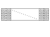
決定部32は、カメラ画像Iに写る人物や、特徴オブジェクトを検出すると、それぞれの検出結果に基づいて、スコアを算出する。具体的には、図10に示すように、装着者Uの視界を複数の領域に分割し、分割した領域ごとにスコアを算出する。
スコアの算出方法の一例として、人物が存在する領域に、減点を行い、装着者U側を向いている人物が存在する領域にはさらに減点を行うとともに、特徴オブジェクトが存在する領域に対しては加点を行う。
そして、決定部32は、例えば、スコアが最も低い領域につい映像コンテンツの表示位置の移動先、すなわち、図3に示した中心座標Cの移動先に決定する。つまり、カメラ画像Iに写る人物に基づき、中心座標Cの移動先を決定することで、人物が存在していない領域が優先的に中心座標Cの移動先として決定されるとともに、複数の人物が存在する場合には、装着者U側を見ていない人物が存在する領域が中心座標Cの移動先として優先的に決定されることになる。
つまり、決定部32は、移動後のHMDの正面方向に判定条件を満たす人物が存在しない向きを中心座標Cの移動先として決定することで、コンテンツ画像の移動頻度を少なくすることができる。
また、決定部32は、特徴オブジェクトに基づき、中心座標Cの移動先を決定することで、装着者Uが特徴オブジェクトを見ているかのように周囲の人物に思わせることができる。したがって、装着者Uが周辺人物に与える不快感そのものを無くすことが可能となる。
なお、特徴オブジェクトによっては、あまりにも長い時間注視すると、かえって不自然に思われるケースも考えられる。このため、HMDの正面方向が特徴オブジェクトとなる時間が所定時間経過した場合には、中心座標Cの移動先を再度決定するようにしてもよい。
図4の説明に戻り、算出部33について説明する。算出部33は、例えば、ジャイロセンサ12の検出結果に基づき、装着者Uの姿勢の変化量を算出する。具体的には、算出部33は、ジャイロセンサ12から入力される姿勢信号に基づき、装着者の頭部の回転量を変化量として算出する。
判定部31によって判定条件が成立したと判定された場合に、後述する表示制御部34によってコンテンツ画像の中心座標Cが初期座標Rpから移動される。この場合に、装着者Uの頭部が回転しなければ、装着者Uが周辺人物を注視しているかの状況が継続することになる。
このため、算出部33は、中心座標Cの移動を契機として、装着者Uの頭部の回転量を算出し、例えば、算出した回転量が閾値を超えた場合に、表示制御部34へ通知する。なお、ここでの閾値とは、HMDの正面方向から当初の周辺人物が外れるのに要する量であるが、例えば、決定部32によって決定された移動先に基づいて決定されたものであってもよい。すなわち、HMDの正面方向が決定部32によって決定された移動先近傍となった場合に、回転量が閾値を超えたと判定することにしてもよい。
表示制御部34は、判定部31によってHMDの正面方向に周辺人物が存在すると判定された場合に、コンテンツ画像の表示位置を移動させる。この際、上述のように、初期座標Rpは、表示装置10における表示領域の中心に設定されている。
したがって、表示制御部34は、初期座標Rpと中心座標Cとの距離が増加するように、中心座標Cを移動させることになる。また、表示制御部34は、決定部32によって決定された移動先へ中心座標Cを移動させる。
この際、例えば、初期座標Rpから中心座標Cが急速に移動させると、コンテンツ画像の表示位置に伴い、コンテンツ画像の視認性が損なわれるおそれがある。また、この場合、中心座標Cの移動に伴い、装着者Uが頭部を急速に回転させると、周辺人物から視線を大きく逸らすことになるので、かえって不信感を与えるケースも考えられる。
このため、表示制御部34は、コンテンツ画像の表示位置を移動させる場合に、コンテンツ画像の移動速度が所定値以下に収まるように表示位置を移動させるとともに、移動前の表示位置と移動後の表示位置との距離が所定範囲内に収まるように表示位置を移動させることが好ましい。
図11は、表示位置の移動時における中心座標Cの遷移図である。また、図12は、頭部の回転量の一例を示す図である。図11に示すように、例えば、初期座標Rpからコンテンツ画像の中心座標Cを右側に移動させる場合を想定する。この場合において、表示制御部34は、中心座標Cの移動速度が所定値以下であり移動前後の中心座標Cの距離が所定値以下となるように、中心座標Cを随時移動させる。
これにより、コンテンツ画像の視認性を損なうことなく、周辺人物に与える不快感を軽減することができるとともに、装着者Uの頭部の回転量を最小限に抑えることができる。この際、中心座標Cが初期座標Rpからずれている期間は、装着者Uが頭部を回転させることが期待される一方で、中心座標Cと初期座標Rpとのずれが十分に小さい場合には、装着者Uが頭部を回転させずに、視線のみを中心座標Cにあわせて移動させる場合が想定される。
このため、初期座標Rpと、移動後の中心座標Cとの距離は、所定値以上であることが好ましい。また、この場合には、表示制御部34は、中心座標Cの移動毎に、算出部33から頭部の回転量を取得し、頭部が回転していない場合にのみ、次の表示位置へ、中心座標Cを移動させることにしてもよい。
その後、図12に示すように、表示位置の移動前後における正面ベクトルVの回転量θが閾値を超えた場合には、表示制御部34は、中心座標Cを初期座標Rpに移動させる。言い換えれば、表示制御部34は、装着者Uの頭部が所望する向きとなった場合には、中心座標Cを初期座標Rpに戻すことで、装着者Uの頭部の回転を止めることができる。
次に、図13および図14を用いて、実施形態に係る情報処理装置1が実行する処理手順について説明する。図13は、実施形態に係る情報処理装置1が実行する処理手順を示すフローチャートである。図14は、図13に示すステップS105の処理手順を示すフローチャートである。なお、以下に示す処理手順は、制御部3によって繰り返し実行される。
図13に示すように、情報処理装置1は、まず、コンテンツ画像を表示中か否かを判定し(ステップS101)、コンテンツ画像の表示中である場合(ステップS101,Yes)、カメラ画像に基づき、周辺人物の認識処理を行う(ステップS102)。
続いて、情報処理装置1は、周辺人物の認識処理の結果に基づき、図6に示した視線条件が成立したか否かを判定する(ステップS103)。情報処理装置1は、ステップS103の判定において、視線条件が成立したと判定した場合(ステップS103,Yes)、表示制御処理へ移行し(ステップS105)、処理を終了する。
また、情報処理装置1は、ステップS103の判定処理において、視線条件が成立してないと判定した場合に(ステップS103,No)、図7に示した距離条件が成立したか否かを判定する(ステップS104)。
情報処理装置1は、ステップS104の判定において、距離条件が成立した場合(ステップS104,Yes)、ステップS105の処理へ移行し、距離条件が成立していないと判定した場合には(ステップS104,No)、処理を終了する。また、情報処理装置1は、ステップS101の判定において、コンテンツ画像を表示していない場合には(ステップS101,No)、ステップS102以降の処理を省略して、処理を終了する。
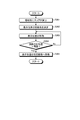
次に、図14を用いて、図13に示したステップS105の処理手順について説明する。図14に示すように、情報処理装置1は、カメラ画像に写る人物や特徴オブジェクトに基づき、領域毎にスコアを算出する(ステップS201)。
続いて、情報処理装置1は、領域毎のスコアに基づいて、映像コンテンツの表示位置の移動先を決定し(ステップS202)、決定した移動先へ表示位置を移動させる(ステップS203)。
続いて、情報処理装置1は、装着者Uの頭部の回転量が閾値よりも大きいか否かを判定し(ステップS204)、回転量が閾値を超えた場合に(ステップS204,Yes)、表示位置を初期座標Rpへ移動させて(ステップS205)、処理を終了する。
また、情報処理装置1は、ステップS204の判定において、回転量が閾値に満たない場合には(ステップS204,No)、ステップS203の処理へ移行する。
[変形例]
上述した実施形態では、HMDの正面方向に周辺人物が存在する場合に、コンテンツ画像の表示位置を移動させることで、装着者Uの視線を誘導する場合について説明したが、これに限定されるものではない。すなわち、装着者Uに対して、警告画像や警告音により、周辺人物の存在を報知することにしてもよい。なお、この場合においては、コンテンツ画像の一部または全ての透過率を上げることで、装着者Uに対して周辺人物を直接視認させることにしてもよい。
上述した実施形態では、HMDの正面方向に周辺人物が存在する場合に、コンテンツ画像の表示位置を移動させることで、装着者Uの視線を誘導する場合について説明したが、これに限定されるものではない。すなわち、装着者Uに対して、警告画像や警告音により、周辺人物の存在を報知することにしてもよい。なお、この場合においては、コンテンツ画像の一部または全ての透過率を上げることで、装着者Uに対して周辺人物を直接視認させることにしてもよい。
また、上述した実施形態では、表示装置10が光学シースルー型の表示装置である場合について説明したが、これに限られず、ビデオシースルー型の表示装置にも同様に適用することが可能である。
上述してきた各実施形態に係る情報処理装置等の情報機器は、例えば図15に示すような構成のコンピュータ1000によって実現される。以下、実施形態に係る情報処理装置1を例に挙げて説明する。図15は、情報処理装置1の機能を実現するコンピュータ1000の一例を示すハードウェア構成図である。コンピュータ1000は、CPU1100、RAM1200、ROM(Read Only Memory)1300、HDD(Hard Disk Drive)1400、通信インターフェイス1500、及び入出力インターフェイス1600を有する。コンピュータ1000の各部は、バス1050によって接続される。
CPU1100は、ROM1300又はHDD1400に格納されたプログラムに基づいて動作し、各部の制御を行う。例えば、CPU1100は、ROM1300又はHDD1400に格納されたプログラムをRAM1200に展開し、各種プログラムに対応した処理を実行する。
ROM1300は、コンピュータ1000の起動時にCPU1100によって実行されるBIOS(Basic Input Output System)等のブートプログラムや、コンピュータ1000のハードウェアに依存するプログラム等を格納する。
HDD1400は、CPU1100によって実行されるプログラム、及び、かかるプログラムによって使用されるデータ等を非一時的に記録する、コンピュータが読み取り可能な記録媒体である。具体的には、HDD1400は、プログラムデータ1450の一例である本開示に係るプログラムを記録する記録媒体である。
通信インターフェイス1500は、コンピュータ1000が外部ネットワーク1550(例えばインターネット)と接続するためのインターフェイスである。例えば、CPU1100は、通信インターフェイス1500を介して、他の機器からデータを受信したり、CPU1100が生成したデータを他の機器へ送信したりする。
入出力インターフェイス1600は、入出力デバイス1650とコンピュータ1000とを接続するためのインターフェイスである。例えば、CPU1100は、入出力インターフェイス1600を介して、キーボードやマウス等の入力デバイスからデータを受信する。また、CPU1100は、入出力インターフェイス1600を介して、ディスプレイやスピーカやプリンタ等の出力デバイスにデータを送信する。また、入出力インターフェイス1600は、所定の記録媒体(メディア)に記録されたプログラム等を読み取るメディアインターフェイスとして機能してもよい。メディアとは、例えばDVD(Digital Versatile Disc)、PD(Phase change rewritable Disk)等の光学記録媒体、MO(Magneto-Optical disk)等の光磁気記録媒体、テープ媒体、磁気記録媒体、または半導体メモリ等である。
例えば、コンピュータ1000が実施形態に係る情報処理装置1として機能する場合、コンピュータ1000のCPU1100は、RAM1200上にロードされたプログラムを実行することにより、取得部30の機能を実現する。また、HDD1400には、本開示に係るプログラムや、記憶部2内のデータが格納される。なお、CPU1100は、プログラムデータ1450をHDD1400から読み取って実行するが、他の例として、外部ネットワーク1550を介して、他の装置からこれらのプログラムを取得してもよい。
なお、本技術は以下のような構成も取ることができる。
(1)
ヘッドマウントディスプレイにコンテンツ画像を表示する表示制御部と、
前記表示制御部による前記コンテンツ画像の表示中において、前記ヘッドマウントディスプレイの周辺環境を撮像したカメラ画像に基づき、前記ヘッドマウントディスプレイの正面方向に周辺人物が存在するか否かを判定する判定部と
を備え、
前記表示制御部は、
前記判定部によって前記周辺人物が存在すると判定された場合に、前記コンテンツ画像の表示位置を移動させる、
情報処理装置。
(2)
前記ヘッドマウントディスプレイは、
光学透過性を有する、
上記(1)に記載の情報処理装置。
(3)
前記ヘッドマウントディスプレイは、
遮光部材を備える、
上記(2)に記載の情報処理装置。
(4)
前記表示制御部は、
前記コンテンツ画像を前記ヘッドマウントディスプレイの表示領域の中央に設定された初期座標から前記コンテンツ画像の中心との距離が増加するように前記コンテンツ画像を移動させる、
上記(1)~(3)のいずれかに記載の情報処理装置。
(5)
前記表示制御部は、
前記コンテンツ画像の表示位置を移動させる場合に、前記コンテンツ画像の移動速度が所定値以下に収まるように前記表示位置を移動させる、
上記(1)~(4)のいずれかに記載の情報処理装置。
(6)
前記表示制御部は、
前記コンテンツ画像の表示位置を移動させる場合に、移動前の前記表示位置と移動後の前記表示位置との距離が所定範囲内に収まるように前記表示位置を移動させる、
上記(1)~(5)のいずれかに記載の情報処理装置。
(7)
前記ヘッドマウントディスプレイの姿勢に関する姿勢信号に基づいて、前記コンテンツ画像の移動前後における前記ヘッドマウントディスプレイの姿勢の変化量を算出する算出部
を備え、
前記表示制御部は、
前記算出部によって算出された前記姿勢の変化量が閾値を超えた場合に、前記コンテンツ画像の表示位置を元に戻す、
上記(1)~(6)のいずれかに記載の情報処理装置。
(8)
前記算出部は、
前記姿勢信号に基づき、前記ヘッドマウントディスプレイの装着者の頭部の回転量を前記変化量として算出し、
前記表示制御部は、
前記回転量が閾値を超えた場合に、前記コンテンツ画像の表示位置を元に戻す、
上記(7)に記載の情報処理装置。
(9)
前記判定部は、
前記ヘッドマウントディスプレイの正面方向に存在する人物の顔の向きに基づいて、前記周辺人物が存在するか否かを判定する、
上記(1)~(8)のいずれかに記載の情報処理装置。
(10)
前記判定部は、
前記ヘッドマウントディスプレイの正面方向と、前記人物の顔の向きとの成す角が所定閾値以内である場合に、前記周辺人物が存在すると判定する、
上記(9)に記載の情報処理装置。
(11)
前記判定部は、
前記ヘッドマウントディスプレイの正面方向において、前記周辺人物が所定時間以上静止している場合に、前記周辺人物が存在すると判定する、
上記(1)~(10)のいずれかに記載の情報処理装置。
(12)
前記判定部は、
前記ヘッドマウントディスプレイの正面方向と、前記周辺人物における特定部位の座標との距離が閾値以下である場合に、前記周辺人物が存在すると判定する、
上記(1)~(11)のいずれかに記載の情報処理装置。
(13)
前記判定部によって前記周辺人物が存在すると判定された場合に、前記コンテンツ画像の表示位置の移動先を前記カメラ画像に基づいて決定する決定部
を備える、
上記(1)~(12)のいずれかに記載の情報処理装置。
(14)
前記決定部は、
前記カメラ画像に写る人物の向きに基づいて、前記コンテンツ画像の表示位置の移動先を決定する、
上記(13)に記載の情報処理装置。
(15)
前記決定部は、
前記カメラ画像に写る人物がいない向きへ前記コンテンツ画像の表示位置の移動先を決定する、
上記(13)または(14)に記載の情報処理装置。
(16)
前記決定部は、
前記カメラ画像に写るオブジェクトのうち、視覚的な特徴を示す視覚条件を満たす特徴オブジェクトの向きへ前記表示位置の移動先を決定する、
上記(13)~(15)のいずれかに記載の情報処理装置。
(17)
コンピュータが
ヘッドマウントディスプレイにコンテンツ画像を表示し、
前記コンテンツ画像の表示中において、前記ヘッドマウントディスプレイの周辺環境を撮像したカメラ画像に基づき、前記ヘッドマウントディスプレイの正面方向に周辺人物が存在するか否かを判定し、
前記周辺人物が存在すると判定された場合に、前記コンテンツ画像の表示位置を移動させる、
情報処理方法。
(18)
コンピュータを
ヘッドマウントディスプレイにコンテンツ画像を表示する表示制御部と、
前記表示制御部による前記コンテンツ画像の表示中において、前記ヘッドマウントディスプレイの周辺環境を撮像したカメラ画像に基づき、前記ヘッドマウントディスプレイの正面方向に周辺人物が存在するか否かを判定する判定部と
として機能させる、情報処理プログラムであって、
前記表示制御部は、
前記判定部によって前記周辺人物が存在すると判定された場合に、前記コンテンツ画像の表示位置を移動させる、
情報処理プログラム。
1 情報処理装置
10 表示装置
30 取得部
31 判定部
32 決定部
33 算出部
34 表示制御部
Rp 初期座標
C 中心座標
10 表示装置
30 取得部
31 判定部
32 決定部
33 算出部
34 表示制御部
Rp 初期座標
C 中心座標
Claims (18)
- ヘッドマウントディスプレイにコンテンツ画像を表示する表示制御部と、
前記表示制御部による前記コンテンツ画像の表示中において、前記ヘッドマウントディスプレイの周辺環境を撮像したカメラ画像に基づき、前記ヘッドマウントディスプレイの正面方向に周辺人物が存在するか否かを判定する判定部と
を備え、
前記表示制御部は、
前記判定部によって前記周辺人物が存在すると判定された場合に、前記コンテンツ画像の表示位置を移動させる、
情報処理装置。 - 前記ヘッドマウントディスプレイは、
光学透過性を有する、
請求項1に記載の情報処理装置。 - 前記ヘッドマウントディスプレイは、
遮光部材を備える、
請求項2に記載の情報処理装置。 - 前記表示制御部は、
前記コンテンツ画像を前記ヘッドマウントディスプレイの表示領域の中央に設定された初期座標から前記コンテンツ画像の中心との距離が増加するように前記コンテンツ画像を移動させる、
請求項1に記載の情報処理装置。 - 前記表示制御部は、
前記コンテンツ画像の表示位置を移動させる場合に、前記コンテンツ画像の移動速度が所定値以下に収まるように前記表示位置を移動させる、
請求項1に記載の情報処理装置。 - 前記表示制御部は、
前記コンテンツ画像の表示位置を移動させる場合に、移動前の前記表示位置と移動後の前記表示位置との距離が所定範囲内に収まるように前記表示位置を移動させる、
請求項1に記載の情報処理装置。 - 前記ヘッドマウントディスプレイの姿勢に関する姿勢信号に基づいて、前記コンテンツ画像の移動前後における前記ヘッドマウントディスプレイの姿勢の変化量を算出する算出部
を備え、
前記表示制御部は、
前記算出部によって算出された前記姿勢の変化量が閾値を超えた場合に、前記コンテンツ画像の表示位置を元に戻す、
請求項1に記載の情報処理装置。 - 前記算出部は、
前記姿勢信号に基づき、前記ヘッドマウントディスプレイの装着者の頭部の回転量を前記変化量として算出し、
前記表示制御部は、
前記回転量が閾値を超えた場合に、前記コンテンツ画像の表示位置を元に戻す、
請求項7に記載の情報処理装置。 - 前記判定部は、
前記ヘッドマウントディスプレイの正面方向に存在する人物の顔の向きに基づいて、前記周辺人物が存在するか否かを判定する、
請求項1に記載の情報処理装置。 - 前記判定部は、
前記ヘッドマウントディスプレイの正面方向と、前記人物の顔の向きとの成す角が所定閾値以内である場合に、前記周辺人物が存在すると判定する、
請求項9に記載の情報処理装置。 - 前記判定部は、
前記ヘッドマウントディスプレイの正面方向において、前記周辺人物が所定時間以上静止している場合に、前記周辺人物が存在すると判定する、
請求項1に記載の情報処理装置。 - 前記判定部は、
前記ヘッドマウントディスプレイの正面方向と、前記周辺人物における特定部位の座標との距離が閾値以下である場合に、前記周辺人物が存在すると判定する、
請求項1に記載の情報処理装置。 - 前記判定部によって前記周辺人物が存在すると判定された場合に、前記コンテンツ画像の表示位置の移動先を前記カメラ画像に基づいて決定する決定部
を備える、
請求項1に記載の情報処理装置。 - 前記決定部は、
前記カメラ画像に写る人物の向きに基づいて、前記コンテンツ画像の表示位置の移動先を決定する、
請求項13に記載の情報処理装置。 - 前記決定部は、
前記カメラ画像に写る人物がいない向きへ前記コンテンツ画像の表示位置の移動先を決定する、
請求項13に記載の情報処理装置。 - 前記決定部は、
前記カメラ画像に写るオブジェクトのうち、視覚的な特徴を示す視覚条件を満たす特徴オブジェクトの向きへ前記表示位置の移動先を決定する、
請求項13に記載の情報処理装置。 - コンピュータが
ヘッドマウントディスプレイにコンテンツ画像を表示し、
前記コンテンツ画像の表示中において、前記ヘッドマウントディスプレイの周辺環境を撮像したカメラ画像に基づき、前記ヘッドマウントディスプレイの正面方向に周辺人物が存在するか否かを判定し、
前記周辺人物が存在すると判定された場合に、前記コンテンツ画像の表示位置を移動させる、
情報処理方法。 - コンピュータを
ヘッドマウントディスプレイにコンテンツ画像を表示する表示制御部と、
前記表示制御部による前記コンテンツ画像の表示中において、前記ヘッドマウントディスプレイの周辺環境を撮像したカメラ画像に基づき、前記ヘッドマウントディスプレイの正面方向に周辺人物が存在するか否かを判定する判定部と
として機能させる、情報処理プログラムであって、
前記表示制御部は、
前記判定部によって前記周辺人物が存在すると判定された場合に、前記コンテンツ画像の表示位置を移動させる、
情報処理プログラム。
Priority Applications (1)
| Application Number | Priority Date | Filing Date | Title |
|---|---|---|---|
| US17/756,419 US12057092B2 (en) | 2019-12-04 | 2020-11-26 | Information processing device and information processing method for a head-mounted display |
Applications Claiming Priority (2)
| Application Number | Priority Date | Filing Date | Title |
|---|---|---|---|
| JP2019219694 | 2019-12-04 | ||
| JP2019-219694 | 2019-12-04 |
Publications (1)
| Publication Number | Publication Date |
|---|---|
| WO2021111975A1 true WO2021111975A1 (ja) | 2021-06-10 |
Family
ID=76221218
Family Applications (1)
| Application Number | Title | Priority Date | Filing Date |
|---|---|---|---|
| PCT/JP2020/044031 WO2021111975A1 (ja) | 2019-12-04 | 2020-11-26 | 情報処理装置、情報処理方法および情報処理プログラム |
Country Status (2)
| Country | Link |
|---|---|
| US (1) | US12057092B2 (ja) |
| WO (1) | WO2021111975A1 (ja) |
Citations (5)
| Publication number | Priority date | Publication date | Assignee | Title |
|---|---|---|---|---|
| JP2007304721A (ja) * | 2006-05-09 | 2007-11-22 | Toyota Motor Corp | 画像処理装置及び画像処理方法 |
| JP2015087909A (ja) * | 2013-10-30 | 2015-05-07 | キヤノン株式会社 | 情報処理システム、情報処理装置、情報処理サーバ、情報処理方法、及びプログラム |
| JP2015090635A (ja) * | 2013-11-07 | 2015-05-11 | コニカミノルタ株式会社 | 透過型hmdを有する情報表示システム及び表示制御プログラム |
| JP2015518580A (ja) * | 2012-04-08 | 2015-07-02 | サムスン エレクトロニクス カンパニー リミテッド | 透明ディスプレイ装置及びそのディスプレイ方法 |
| JP2017149335A (ja) * | 2016-02-25 | 2017-08-31 | 京セラ株式会社 | 運転支援情報表示装置 |
Family Cites Families (2)
| Publication number | Priority date | Publication date | Assignee | Title |
|---|---|---|---|---|
| US9753285B2 (en) | 2013-03-29 | 2017-09-05 | Sony Corporation | Information processing device, notification state control method, and program |
| US9898868B2 (en) * | 2014-11-06 | 2018-02-20 | Seiko Epson Corporation | Display device, method of controlling the same, and program |
-
2020
- 2020-11-26 WO PCT/JP2020/044031 patent/WO2021111975A1/ja active Application Filing
- 2020-11-26 US US17/756,419 patent/US12057092B2/en active Active
Patent Citations (5)
| Publication number | Priority date | Publication date | Assignee | Title |
|---|---|---|---|---|
| JP2007304721A (ja) * | 2006-05-09 | 2007-11-22 | Toyota Motor Corp | 画像処理装置及び画像処理方法 |
| JP2015518580A (ja) * | 2012-04-08 | 2015-07-02 | サムスン エレクトロニクス カンパニー リミテッド | 透明ディスプレイ装置及びそのディスプレイ方法 |
| JP2015087909A (ja) * | 2013-10-30 | 2015-05-07 | キヤノン株式会社 | 情報処理システム、情報処理装置、情報処理サーバ、情報処理方法、及びプログラム |
| JP2015090635A (ja) * | 2013-11-07 | 2015-05-11 | コニカミノルタ株式会社 | 透過型hmdを有する情報表示システム及び表示制御プログラム |
| JP2017149335A (ja) * | 2016-02-25 | 2017-08-31 | 京セラ株式会社 | 運転支援情報表示装置 |
Also Published As
| Publication number | Publication date |
|---|---|
| US12057092B2 (en) | 2024-08-06 |
| US20230005454A1 (en) | 2023-01-05 |
Similar Documents
| Publication | Publication Date | Title |
|---|---|---|
| CN110647237B (zh) | 在人工现实环境中基于手势的内容共享 | |
| US10281978B2 (en) | Perception based predictive tracking for head mounted displays | |
| EP3000020B1 (en) | Hologram anchoring and dynamic positioning | |
| US9728010B2 (en) | Virtual representations of real-world objects | |
| US9122053B2 (en) | Realistic occlusion for a head mounted augmented reality display | |
| US11127380B2 (en) | Content stabilization for head-mounted displays | |
| US20150212576A1 (en) | Radial selection by vestibulo-ocular reflex fixation | |
| US20130282345A1 (en) | Context aware surface scanning and reconstruction | |
| US20140002495A1 (en) | Multi-node poster location | |
| KR20220120649A (ko) | 인공 현실 콘텐츠의 가변 초점 디스플레이를 갖는 인공 현실 시스템 | |
| US11609428B2 (en) | Information processing apparatus and information processing method | |
| WO2014085789A1 (en) | Direct hologram manipulation using imu | |
| WO2019142560A1 (ja) | 視線を誘導する情報処理装置 | |
| US10771707B2 (en) | Information processing device and information processing method | |
| JP6693223B2 (ja) | 情報処理装置、情報処理方法、及びプログラム | |
| US20210303258A1 (en) | Information processing device, information processing method, and recording medium | |
| US11151804B2 (en) | Information processing device, information processing method, and program | |
| KR20230026503A (ko) | 사회적 거리두기를 사용한 증강 현실 경험들 | |
| US20190369807A1 (en) | Information processing device, information processing method, and program | |
| WO2021100553A1 (ja) | 情報処理装置、情報処理方法および情報処理プログラム | |
| JP6784289B2 (ja) | 情報処理装置、情報処理方法、及びプログラム | |
| US20230300290A1 (en) | Information display system, information display method, and non-transitory recording medium | |
| WO2021111975A1 (ja) | 情報処理装置、情報処理方法および情報処理プログラム | |
| WO2020195292A1 (ja) | 感覚器オブジェクトを表示する情報処理装置 | |
| US20230206622A1 (en) | Information processing device, information processing method, and program |
Legal Events
| Date | Code | Title | Description |
|---|---|---|---|
| 121 | Ep: the epo has been informed by wipo that ep was designated in this application |
Ref document number: 20896391 Country of ref document: EP Kind code of ref document: A1 |
|
| NENP | Non-entry into the national phase |
Ref country code: DE |
|
| 122 | Ep: pct application non-entry in european phase |
Ref document number: 20896391 Country of ref document: EP Kind code of ref document: A1 |
|
| NENP | Non-entry into the national phase |
Ref country code: JP |