WO2021111765A1 - Vehicle driving system - Google Patents
Vehicle driving system Download PDFInfo
- Publication number
- WO2021111765A1 WO2021111765A1 PCT/JP2020/040220 JP2020040220W WO2021111765A1 WO 2021111765 A1 WO2021111765 A1 WO 2021111765A1 JP 2020040220 W JP2020040220 W JP 2020040220W WO 2021111765 A1 WO2021111765 A1 WO 2021111765A1
- Authority
- WO
- WIPO (PCT)
- Prior art keywords
- unit
- vehicle
- driver
- driving
- hmd
- Prior art date
Links
- 238000004891 communication Methods 0.000 claims abstract description 137
- 230000001133 acceleration Effects 0.000 claims abstract description 31
- 230000005540 biological transmission Effects 0.000 claims abstract description 25
- 238000000034 method Methods 0.000 claims description 72
- 238000012360 testing method Methods 0.000 claims description 56
- 238000001514 detection method Methods 0.000 claims description 15
- 230000004044 response Effects 0.000 claims description 14
- 230000008859 change Effects 0.000 claims description 8
- 230000008569 process Effects 0.000 description 46
- 238000012545 processing Methods 0.000 description 28
- 230000006870 function Effects 0.000 description 22
- 238000003745 diagnosis Methods 0.000 description 19
- 210000003128 head Anatomy 0.000 description 13
- 238000003384 imaging method Methods 0.000 description 12
- 238000012544 monitoring process Methods 0.000 description 10
- 210000001508 eye Anatomy 0.000 description 9
- 230000005856 abnormality Effects 0.000 description 8
- 230000000694 effects Effects 0.000 description 7
- 230000015654 memory Effects 0.000 description 7
- 238000010586 diagram Methods 0.000 description 5
- 238000012797 qualification Methods 0.000 description 4
- 238000012508 change request Methods 0.000 description 3
- 239000003814 drug Substances 0.000 description 3
- 229940079593 drug Drugs 0.000 description 3
- 230000002093 peripheral effect Effects 0.000 description 3
- 238000001228 spectrum Methods 0.000 description 3
- LFQSCWFLJHTTHZ-UHFFFAOYSA-N Ethanol Chemical compound CCO LFQSCWFLJHTTHZ-UHFFFAOYSA-N 0.000 description 2
- 230000002411 adverse Effects 0.000 description 2
- 230000003190 augmentative effect Effects 0.000 description 2
- 210000005252 bulbus oculi Anatomy 0.000 description 2
- 230000000295 complement effect Effects 0.000 description 2
- 239000002131 composite material Substances 0.000 description 2
- 239000000446 fuel Substances 0.000 description 2
- 239000004065 semiconductor Substances 0.000 description 2
- 238000012546 transfer Methods 0.000 description 2
- 230000007704 transition Effects 0.000 description 2
- 208000036827 Infectious disease carrier Diseases 0.000 description 1
- 230000004397 blinking Effects 0.000 description 1
- 230000036772 blood pressure Effects 0.000 description 1
- 210000004556 brain Anatomy 0.000 description 1
- 238000006243 chemical reaction Methods 0.000 description 1
- 230000007423 decrease Effects 0.000 description 1
- 238000005516 engineering process Methods 0.000 description 1
- 238000002347 injection Methods 0.000 description 1
- 239000007924 injection Substances 0.000 description 1
- 230000035987 intoxication Effects 0.000 description 1
- 231100000566 intoxication Toxicity 0.000 description 1
- 206010025482 malaise Diseases 0.000 description 1
- 239000000203 mixture Substances 0.000 description 1
- 238000012986 modification Methods 0.000 description 1
- 230000004048 modification Effects 0.000 description 1
- 210000001747 pupil Anatomy 0.000 description 1
- XLYOFNOQVPJJNP-UHFFFAOYSA-N water Substances O XLYOFNOQVPJJNP-UHFFFAOYSA-N 0.000 description 1
Images


Classifications
-
- G—PHYSICS
- G05—CONTROLLING; REGULATING
- G05D—SYSTEMS FOR CONTROLLING OR REGULATING NON-ELECTRIC VARIABLES
- G05D1/00—Control of position, course or altitude of land, water, air, or space vehicles, e.g. automatic pilot
- G05D1/0011—Control of position, course or altitude of land, water, air, or space vehicles, e.g. automatic pilot associated with a remote control arrangement
- G05D1/0038—Control of position, course or altitude of land, water, air, or space vehicles, e.g. automatic pilot associated with a remote control arrangement by providing the operator with simple or augmented images from one or more cameras located onboard the vehicle, e.g. tele-operation
-
- B—PERFORMING OPERATIONS; TRANSPORTING
- B60—VEHICLES IN GENERAL
- B60W—CONJOINT CONTROL OF VEHICLE SUB-UNITS OF DIFFERENT TYPE OR DIFFERENT FUNCTION; CONTROL SYSTEMS SPECIALLY ADAPTED FOR HYBRID VEHICLES; ROAD VEHICLE DRIVE CONTROL SYSTEMS FOR PURPOSES NOT RELATED TO THE CONTROL OF A PARTICULAR SUB-UNIT
- B60W60/00—Drive control systems specially adapted for autonomous road vehicles
- B60W60/005—Handover processes
- B60W60/0053—Handover processes from vehicle to occupant
-
- B—PERFORMING OPERATIONS; TRANSPORTING
- B60—VEHICLES IN GENERAL
- B60K—ARRANGEMENT OR MOUNTING OF PROPULSION UNITS OR OF TRANSMISSIONS IN VEHICLES; ARRANGEMENT OR MOUNTING OF PLURAL DIVERSE PRIME-MOVERS IN VEHICLES; AUXILIARY DRIVES FOR VEHICLES; INSTRUMENTATION OR DASHBOARDS FOR VEHICLES; ARRANGEMENTS IN CONNECTION WITH COOLING, AIR INTAKE, GAS EXHAUST OR FUEL SUPPLY OF PROPULSION UNITS IN VEHICLES
- B60K28/00—Safety devices for propulsion-unit control, specially adapted for, or arranged in, vehicles, e.g. preventing fuel supply or ignition in the event of potentially dangerous conditions
- B60K28/10—Safety devices for propulsion-unit control, specially adapted for, or arranged in, vehicles, e.g. preventing fuel supply or ignition in the event of potentially dangerous conditions responsive to conditions relating to the vehicle
-
- B—PERFORMING OPERATIONS; TRANSPORTING
- B60—VEHICLES IN GENERAL
- B60K—ARRANGEMENT OR MOUNTING OF PROPULSION UNITS OR OF TRANSMISSIONS IN VEHICLES; ARRANGEMENT OR MOUNTING OF PLURAL DIVERSE PRIME-MOVERS IN VEHICLES; AUXILIARY DRIVES FOR VEHICLES; INSTRUMENTATION OR DASHBOARDS FOR VEHICLES; ARRANGEMENTS IN CONNECTION WITH COOLING, AIR INTAKE, GAS EXHAUST OR FUEL SUPPLY OF PROPULSION UNITS IN VEHICLES
- B60K35/00—Arrangement of adaptations of instruments
-
- B60K35/28—
-
- B—PERFORMING OPERATIONS; TRANSPORTING
- B60—VEHICLES IN GENERAL
- B60W—CONJOINT CONTROL OF VEHICLE SUB-UNITS OF DIFFERENT TYPE OR DIFFERENT FUNCTION; CONTROL SYSTEMS SPECIALLY ADAPTED FOR HYBRID VEHICLES; ROAD VEHICLE DRIVE CONTROL SYSTEMS FOR PURPOSES NOT RELATED TO THE CONTROL OF A PARTICULAR SUB-UNIT
- B60W40/00—Estimation or calculation of non-directly measurable driving parameters for road vehicle drive control systems not related to the control of a particular sub unit, e.g. by using mathematical models
- B60W40/08—Estimation or calculation of non-directly measurable driving parameters for road vehicle drive control systems not related to the control of a particular sub unit, e.g. by using mathematical models related to drivers or passengers
-
- B—PERFORMING OPERATIONS; TRANSPORTING
- B60—VEHICLES IN GENERAL
- B60W—CONJOINT CONTROL OF VEHICLE SUB-UNITS OF DIFFERENT TYPE OR DIFFERENT FUNCTION; CONTROL SYSTEMS SPECIALLY ADAPTED FOR HYBRID VEHICLES; ROAD VEHICLE DRIVE CONTROL SYSTEMS FOR PURPOSES NOT RELATED TO THE CONTROL OF A PARTICULAR SUB-UNIT
- B60W50/00—Details of control systems for road vehicle drive control not related to the control of a particular sub-unit, e.g. process diagnostic or vehicle driver interfaces
- B60W50/08—Interaction between the driver and the control system
- B60W50/12—Limiting control by the driver depending on vehicle state, e.g. interlocking means for the control input for preventing unsafe operation
-
- B—PERFORMING OPERATIONS; TRANSPORTING
- B60—VEHICLES IN GENERAL
- B60W—CONJOINT CONTROL OF VEHICLE SUB-UNITS OF DIFFERENT TYPE OR DIFFERENT FUNCTION; CONTROL SYSTEMS SPECIALLY ADAPTED FOR HYBRID VEHICLES; ROAD VEHICLE DRIVE CONTROL SYSTEMS FOR PURPOSES NOT RELATED TO THE CONTROL OF A PARTICULAR SUB-UNIT
- B60W60/00—Drive control systems specially adapted for autonomous road vehicles
- B60W60/005—Handover processes
- B60W60/0059—Estimation of the risk associated with autonomous or manual driving, e.g. situation too complex, sensor failure or driver incapacity
-
- G—PHYSICS
- G05—CONTROLLING; REGULATING
- G05D—SYSTEMS FOR CONTROLLING OR REGULATING NON-ELECTRIC VARIABLES
- G05D1/00—Control of position, course or altitude of land, water, air, or space vehicles, e.g. automatic pilot
- G05D1/0011—Control of position, course or altitude of land, water, air, or space vehicles, e.g. automatic pilot associated with a remote control arrangement
- G05D1/0016—Control of position, course or altitude of land, water, air, or space vehicles, e.g. automatic pilot associated with a remote control arrangement characterised by the operator's input device
-
- G—PHYSICS
- G08—SIGNALLING
- G08G—TRAFFIC CONTROL SYSTEMS
- G08G1/00—Traffic control systems for road vehicles
- G08G1/16—Anti-collision systems
-
- B60K2360/176—
-
- B60K2360/178—
-
- B60K2360/179—
-
- B—PERFORMING OPERATIONS; TRANSPORTING
- B60—VEHICLES IN GENERAL
- B60W—CONJOINT CONTROL OF VEHICLE SUB-UNITS OF DIFFERENT TYPE OR DIFFERENT FUNCTION; CONTROL SYSTEMS SPECIALLY ADAPTED FOR HYBRID VEHICLES; ROAD VEHICLE DRIVE CONTROL SYSTEMS FOR PURPOSES NOT RELATED TO THE CONTROL OF A PARTICULAR SUB-UNIT
- B60W50/00—Details of control systems for road vehicle drive control not related to the control of a particular sub-unit, e.g. process diagnostic or vehicle driver interfaces
- B60W50/08—Interaction between the driver and the control system
- B60W50/14—Means for informing the driver, warning the driver or prompting a driver intervention
- B60W2050/146—Display means
-
- B—PERFORMING OPERATIONS; TRANSPORTING
- B60—VEHICLES IN GENERAL
- B60W—CONJOINT CONTROL OF VEHICLE SUB-UNITS OF DIFFERENT TYPE OR DIFFERENT FUNCTION; CONTROL SYSTEMS SPECIALLY ADAPTED FOR HYBRID VEHICLES; ROAD VEHICLE DRIVE CONTROL SYSTEMS FOR PURPOSES NOT RELATED TO THE CONTROL OF A PARTICULAR SUB-UNIT
- B60W2420/00—Indexing codes relating to the type of sensors based on the principle of their operation
- B60W2420/40—Photo or light sensitive means, e.g. infrared sensors
- B60W2420/403—Image sensing, e.g. optical camera
-
- B—PERFORMING OPERATIONS; TRANSPORTING
- B60—VEHICLES IN GENERAL
- B60W—CONJOINT CONTROL OF VEHICLE SUB-UNITS OF DIFFERENT TYPE OR DIFFERENT FUNCTION; CONTROL SYSTEMS SPECIALLY ADAPTED FOR HYBRID VEHICLES; ROAD VEHICLE DRIVE CONTROL SYSTEMS FOR PURPOSES NOT RELATED TO THE CONTROL OF A PARTICULAR SUB-UNIT
- B60W2540/00—Input parameters relating to occupants
- B60W2540/01—Occupants other than the driver
-
- B—PERFORMING OPERATIONS; TRANSPORTING
- B60—VEHICLES IN GENERAL
- B60W—CONJOINT CONTROL OF VEHICLE SUB-UNITS OF DIFFERENT TYPE OR DIFFERENT FUNCTION; CONTROL SYSTEMS SPECIALLY ADAPTED FOR HYBRID VEHICLES; ROAD VEHICLE DRIVE CONTROL SYSTEMS FOR PURPOSES NOT RELATED TO THE CONTROL OF A PARTICULAR SUB-UNIT
- B60W2540/00—Input parameters relating to occupants
- B60W2540/24—Drug level, e.g. alcohol
-
- B—PERFORMING OPERATIONS; TRANSPORTING
- B60—VEHICLES IN GENERAL
- B60W—CONJOINT CONTROL OF VEHICLE SUB-UNITS OF DIFFERENT TYPE OR DIFFERENT FUNCTION; CONTROL SYSTEMS SPECIALLY ADAPTED FOR HYBRID VEHICLES; ROAD VEHICLE DRIVE CONTROL SYSTEMS FOR PURPOSES NOT RELATED TO THE CONTROL OF A PARTICULAR SUB-UNIT
- B60W2556/00—Input parameters relating to data
- B60W2556/45—External transmission of data to or from the vehicle
-
- B—PERFORMING OPERATIONS; TRANSPORTING
- B60—VEHICLES IN GENERAL
- B60W—CONJOINT CONTROL OF VEHICLE SUB-UNITS OF DIFFERENT TYPE OR DIFFERENT FUNCTION; CONTROL SYSTEMS SPECIALLY ADAPTED FOR HYBRID VEHICLES; ROAD VEHICLE DRIVE CONTROL SYSTEMS FOR PURPOSES NOT RELATED TO THE CONTROL OF A PARTICULAR SUB-UNIT
- B60W2756/00—Output or target parameters relating to data
- B60W2756/10—Involving external transmission of data to or from the vehicle
Definitions
- the present disclosure relates to a vehicle driving system including a controlled vehicle and a wireless communication device.
- Patent Document 1 proposes a technique that enables a occupant in the passenger seat or the like to perform emergency driving on behalf of the driver when the driver during manual driving suddenly becomes ill.
- One aspect of the present disclosure is to enable the driver to cope with the manual driving of the autonomous driving vehicle and to improve the degree of freedom in the configuration of the autonomous driving vehicle.
- One aspect of the present disclosure is a vehicle driving system, comprising at least one wireless communication device and a controlled vehicle.
- the wireless communication device is owned by the driver.
- the controlled vehicle can be automatically driven and manually driven, and can be manually driven by a command from a wireless communication device.
- the controlled vehicle includes at least one sensing unit, an information detecting unit, an information transmitting unit, and a driving control unit.
- the sensing unit is configured to sense at least the traveling direction side of the controlled vehicle.
- the information detection unit is configured to detect the traveling information of the controlled vehicle.
- the information transmission unit is configured to transmit a sensing image based on the sensing result by the sensing unit and driving information to the wireless communication device when the manual operation is performed.
- the operation control unit is configured to perform acceleration / deceleration control and steering control of the controlled vehicle in response to an operation command from the wireless communication device when performing manual operation.
- the wireless communication device includes an information acquisition unit, a display control unit, an operation reception unit, and a command transmission unit.
- the information acquisition unit is configured to acquire sensing images and traveling information from the controlled vehicle.
- the display control unit is configured to display a sensing image and an image based on driving information on the display unit.
- the operation reception unit is configured to receive driving operations related to acceleration / deceleration control and steering control of the controlled vehicle by the driver who operates the wireless communication device.
- the command transmitting unit is configured to transmit a command based on the driving operation as a driving command to the controlled vehicle.
- the controlled vehicle can be manually driven by operating the wireless communication device regardless of the position of the wireless communication device.
- the degree of freedom in the configuration of the controlled vehicle can be improved.
- the present disclosure provides a vehicle driving system 1, which is an "HMD driving operation system” that does not limit the position of the driver when switching to manual driving due to an abnormality in the automatic driving system, a performance limit of the system, or the like.
- the HMD 30 is a head-mounted display device.
- the HMD 30 can adopt any shape as long as it can cover the entire field of view of the user with the display unit, such as a goggle type and a full-face helmet type.
- manual driving using HMD30 is performed. Will be implemented.
- manual driving using the HMD30 the HMD30 is attached to the head and the controller 50 is used to operate the driver. By providing the minimum visibility information necessary for driving to a person who has a driving license and is permitted to perform the manual driving. Ensure safe driving operation using the controller 50.
- the driver is not limited to the position of the driver who has a driving license, and even if the driver is in any seat in the vehicle or outside the vehicle, the automatic driving state and the manual driving state can be obtained. Can be safely migrated in both directions.
- the vehicle driving system 1 of the present disclosure converts the viewpoint from one or a plurality of images appropriately selected from the camera unit 25 around the vehicle and synthesizes the HMD 30 regardless of where the qualified driver is seated inside or outside the vehicle. By projecting inside, it is possible for a qualified driver to drive with a view as if he / she is seated in a conventional driver's seat.
- the HMD 30 and the controller 50 in the present embodiment correspond to the wireless communication device in the present disclosure
- the vehicle 10 in the present embodiment corresponds to the controlled vehicle in the present disclosure
- the camera unit 25 in the present embodiment corresponds to the imaging unit in the present disclosure
- S1, S3, S4, S5, S7 in the present embodiment correspond to the first imaging unit in the present disclosure
- S2 and S6 in the embodiment correspond to the second imaging unit in the present disclosure
- the sensors 21 in the present embodiment correspond to the information detection unit in the present disclosure.
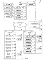
- the vehicle driving system 1 shown in FIG. 1 includes a vehicle 10, a head-mounted display device (hereinafter, HMD) 30, and a controller 50. Further, the vehicle driving system 1 may include a server 70.
- HMD head-mounted display device
- the vehicle 10 is capable of automatic driving and manual driving, and is configured to be capable of performing manual driving by a command from a wireless communication device as a part of the manual driving mode.
- the HMD 30 and the controller 50 correspond to a wireless communication device.
- the vehicle 10 can carry out automatic driving without driver responsibility.
- Autonomous driving without driver responsibility means automatic driving that does not force the conventional driver to change driving in the event of a system abnormality.
- the manual driving includes a conventional manual mode and an in-vehicle HMD mode, which will be described later.
- the vehicle 10 includes a control unit 11, sensors 21, an accelerator 22, a brake 23, a steering wheel 24, a camera unit 25, and a controlled unit 26.
- the sensors 21 are configured to detect the traveling information of the vehicle 10.
- the traveling information is information related to the traveling of the vehicle 10.
- the traveling information may include the vehicle speed, steering angle, accelerator and brake operating states, acceleration, and the like of the vehicle 10.
- the accelerator 22 is an accelerator pedal arranged in the driver's seat of the vehicle 10.
- the brake 23 is a brake pedal arranged in the driver's seat of the vehicle 10.
- the steering wheel 24 is a steering wheel arranged in the driver's seat of the vehicle 10. The operation contents for these are recognized by the control unit 11, and the control unit 11 transmits a command corresponding to the operation contents to the controlled unit 26.
- the camera unit 25 is configured to capture at least the traveling direction side of the vehicle 10. The details of the camera unit 25 will be described later.
- the controlled unit 26 is configured as an actuator that controls acceleration / deceleration and steering of the vehicle 10.
- the controlled unit 26 includes, for example, a traveling motor for controlling acceleration / deceleration, a fuel injection device, a brake oil pressure control device, a steering motor for controlling a steering angle, and the like.
- the HMD 30 is a device capable of wirelessly communicating with the vehicle 10 and providing the driver with information necessary for remotely controlling the vehicle 10 by means of an image.
- the HMD 30 is a device that is separated from the controller 50, is configured to be mounted on the driver's head, and is possessed by the driver.
- the HMD 30 includes a control unit 31, a sensor unit 41, and a display unit 42.
- the sensor unit 41 has a function of detecting the position of the HMD 30, the ambient illuminance, the movement of the driver's eyeball, the presence or absence of blinking in the driver's eyes, the orientation of the driver's head, and the like.
- the display unit 42 is configured as a display that displays an image in response to a command from the control unit 31.
- the HMD 30 includes an inner surface that covers most of the driver's field of view from the outside with both eyes of the driver, and the display unit 42 causes the display unit 42 to display an image on the display surface along the inner surface.
- the controller 50 is a device capable of wireless communication with the vehicle 10 and accepting an operation for the driver to drive the vehicle 10.
- the controller 50 includes a control unit 51, a sensor unit 61, and an operation unit 62.
- the sensor unit 61 has a function of detecting voice, a driver's fingerprint, and the like.
- the operation unit 62 includes a plurality of buttons, switches such as sticks, a touch panel, and the like provided in a general controller.
- the control unit 11 of the vehicle 10, the control unit 31 of the HMD 30, and the control unit 51 of the controller 50 are CPUs 12, 32, 52, respectively, and semiconductor memories such as RAM or ROM (hereinafter, memories 13, 33, 53). And comprises a microcomputer having. Each function of the control units 11, 31, and 51 is realized by the CPUs 12, 32, and 52 executing a program stored in the non-transitional substantive recording medium.
- the memories 13, 33, and 53 correspond to the non-transitional substantive recording medium in which the program is stored. Moreover, when this program is executed, the method corresponding to the program is executed.
- the non-transitional substantive recording medium means that electromagnetic waves are excluded from the recording medium.
- the control units 11, 31, and 51 may include one microcomputer or a plurality of microcomputers.
- the control units 11, 31, and 51 include each unit described later.
- the method for realizing the functions of each of these parts is not limited to software, and some or all of the functions may be realized by using one or more hardware.
- the electronic circuit may be realized by a digital circuit, an analog circuit, or a combination thereof.
- the server 70 is a device that provides the vehicle 10 with information necessary for automatic driving, information necessary for authentication with the HMD 30, and the like.
- the server 70 includes various information providing units 71 and an authentication unit 72.
- the various information providing units 71 are provided with map information and the like, and provide necessary data to the vehicle 10 in response to a request from the vehicle 10.
- the authentication unit 72 records qualification information that is information about a qualified driver in advance, and provides the qualification information to the vehicle 10 in response to a request from the vehicle 10 or the like.
- the control unit 11 of the vehicle 10 includes an automatic driving unit 16, an HMD driving unit 17, and a communication unit 19.
- the automatic driving unit 16 is configured to carry out automatic driving that does not require the operation of the driver.
- the HMD operation unit 17 is configured to perform each function for performing manual operation using the HMD 30. As shown in FIG. 2, the HMD operation unit 17 includes an information transmission unit 17A, an operation control unit 17B, a suitability determination unit 17C, a control prohibition unit 17D, an information storage unit 17E, a seat position acquisition unit 17F, and the like. A mode selection unit 17G is provided.
- the information transmission unit 17A is configured to transmit the image captured by the camera unit 25 and the driving information to the HMD 30 when the manual operation using the HMD 30 is performed.
- the information transmission unit 17A acquires the captured image obtained by the camera unit 25 and the traveling information obtained by the sensors 21, and transmits the captured image and the traveling information to the HMD 30 using the communication unit 19.
- the operation control unit 17B is configured to perform acceleration / deceleration control and steering control of the vehicle 10 in response to an operation command from the controller 50 when manual operation using the HMD 30 is performed. At this time, the operation control unit 17B converts the operation amount to the operation unit 62 included in the operation command into the control amount of the controlled unit 26, and converts the control amount into the control amount and steering control for acceleration / deceleration control. As a control amount for, is sent to the controlled unit 26.
- the suitability determination unit 17C determines whether or not the driver is suitable for driving the vehicle 10 in the driving setting process described later.
- the suitability determination unit 17C determines whether or not the driver has a license to drive the vehicle 10 and whether or not the driver is intoxicated. Whether or not the driver has a license is the information in which the driver's personal information (ID & security code or biometric information) is registered by communicating with the server 70 in which the information about the qualified driver is registered. Judgment is made based on whether or not it matches with. In addition, the intoxicated state indicates a state in which normal driving may not be possible due to the influence of alcohol or drugs. Whether or not the person is intoxicated is determined by comparing the degree of intoxication with a threshold value prepared in advance.
- the degree of drunkenness indicates the degree of drunkenness of the driver and the degree of adverse effects of the drug.
- the drunkenness is determined by, for example, observing the movement of the driver's eyeball by the driver monitoring unit 36 of the HMD30, and if the drunkenness is low, it is determined that the drunkenness and the adverse effects of the drug are small.
- the drunkenness may be determined by an alcohol sensor or the like.
- the control prohibition unit 17D prohibits the acceleration / deceleration control and steering control of the vehicle 10 by the operation control unit 17B when it is determined that the driver is not suitable for driving. In the driving setting process described later, the control prohibition unit 17D forcibly stops the vehicle 10 in S290 regardless of the driver's intention.
- the information storage unit 17E is configured to store information that identifies the driver in a preset recording unit.
- the control prohibition unit 17D stores various information in the memory 13 or the like in S310.
- the process of storing the information that identifies the driver in the preset recording unit may be performed by the HMD 30, the controller 50, another server, or the like other than the vehicle 10.
- the seat position acquisition unit 17F is configured to acquire driver's seat information for specifying the position of the driver's seat of the vehicle 10.
- a position preset in the vehicle 10 is recorded in the memory 13, and the seat position acquisition unit 17F acquires information regarding this position.
- the driver's seat information may be changed at the will of the driver. For example, it is preferable that a right-hand drive vehicle, a left-hand drive vehicle, or the like can be selected.
- the seat position acquisition unit 17F may set the optimum driver's seat position according to the traffic division of the road on which the vehicle 10 travels. For example, the driver's seat of a right-hand drive vehicle may be set in the area of left-hand drive, and the driver's seat of a left-hand drive vehicle may be set in the area of right-hand drive.
- the mode selection unit 17G is configured to select one of a plurality of operation modes in the operation setting process according to the failure state of the vehicle 10 and the intention of the occupant of the vehicle 10.
- a plurality of operation modes an automatic mode, an in-vehicle HMD mode, an out-of-vehicle HMD mode, a conventional manual mode, and the like are prepared.
- the automatic mode is a mode in which the vehicle 10 is automatically driven without requiring the driver's operation.
- the in-vehicle HMD mode is a mode for the driver in the vehicle 10 to perform manual driving using the HMD 30.
- the in-vehicle HMD mode it is possible to adopt a configuration in which the HMD 30 and the vehicle 10 directly perform wireless communication without going through the Internet network 5.
- the out-of-vehicle HMD mode is a mode for a driver outside the vehicle 10 to perform manual driving using the HMD 30.
- communication is performed via the Internet network 5.
- the conventional manual mode is a mode for the driver to manually drive the vehicle 10 by using the pedal or the like of the vehicle 10 without using the HMD 30 and the controller 50.
- the communication unit 19 is configured as a well-known communication module for communicating via the Internet network 5.
- the communication unit 19 performs wireless communication with a wireless base station (not shown) and is connected to the Internet network 5 via the wireless base station.
- the communication unit 39 of the HMD 30 and the communication unit 59 of the controller 50 are configured in the same manner as the communication unit 19 of the vehicle 10.
- the control unit 31 of the HMD 30 includes an information acquisition unit 35, a driver monitoring unit 36, a display control unit 37A, a movement detection unit 37B, and a communication unit 39.
- an authentication execution unit 38 may be provided.
- the information acquisition unit 35 is configured to acquire the captured image and the traveling information from the vehicle 10 by using the communication unit 39.
- the driver monitoring unit 36 monitors whether or not the driver's condition is good by using the detection result of the sensor unit 41. For example, when the number of blinks of the driver decreases, it is determined that the driver's condition is not good.
- the driver monitoring unit 36 may monitor the driver's state by, for example, sensing biological information such as heartbeat and blood pressure using a video spectrum camera. In addition, any monitoring method can be adopted.
- the display control unit 37A is configured to display the captured image and the display image based on the driving information on the display unit 42. Details will be described later.
- the movement detection unit 37B is configured to detect the movement of the driver's head.
- the authentication implementation unit 38 recognizes the driver's iris and authenticates the driver. Not limited to iris recognition, a well-known authentication method may be adopted.
- the control unit 51 of the controller 50 includes an operation reception unit 57A, a command transmission unit 57B, an authentication execution unit 58, and a communication unit 59.
- the authentication execution unit 58 and the communication unit 59 are configured in the same manner as the authentication execution unit 38 and the communication unit 39 of the HMD 30.
- the operation reception unit 57A is configured to receive a driving operation related to acceleration / deceleration control and steering control of the vehicle 10 by the driver operating the operation unit 62.
- the operation reception unit 57A has a function of detecting the amount of operation on the operation unit 62.
- the command transmission unit 57B is configured to transmit a command based on the driving operation as a driving command to the vehicle 10 via the communication unit 59.
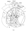
- the camera unit 25 includes a plurality of cameras S1 to S7 and the like. Although some cameras are not shown in FIG. 3, the camera unit 25 is configured so that the surroundings of the vehicle can be monitored without gaps by using a large number of cameras including the omitted cameras.
- the cameras S1, S3, S4, S5 and S7 are configured to perform sensing by the first sensing method.
- the first sensing method for example, an imaging method using a visible light camera can be applied.
- the cameras S2 and S6 are configured to perform sensing by a second sensing method different from the first sensing method.
- the second sensing method for example, an imaging method using an infrared camera or a spectrum camera can be applied.
- the sensing area of the cameras S1, S3, S4, S5, S7 by the first sensing method and the sensing area of the cameras S2, S6 by the second sensing method include the traveling direction of the vehicle 10 and the side of the vehicle 10. At least a part of the sensing area in different methods is set to overlap. Since the cameras S1 to S7 generate captured images, it can be said that the sensing region is the imaging region.
- the imaging region R1 of the camera S1 and the imaging region R3 of the camera S3 are set so as to overlap the imaging region R2 of the camera S2, and the imaging region R5 of the camera S5 overlaps with the imaging region R6 of the camera S6. Is set to.
- the control unit 11 acquires images captured by the plurality of cameras S1 to S7 as sensing images.
- S1 to S7 can be radar (Lidar, millimeter wave) or It may be configured as an arbitrary sensing unit with a sonar or the like.
- the control unit 11 may convert the sensing result into an image.
- the control unit 11 may generate an image according to the position of the AF point measured by the radar.
- another sensing method is used to compensate for the performance limit of one sensing method. If sufficient sensing results can be obtained with one sensing method, only one sensing method may be adopted.
- the display control unit 37A synthesizes the captured images obtained from the camera unit 25 to generate one or a plurality of captured images, and transforms the coordinates of the captured images to generate a display image with the driver's seat V of the vehicle 10 as a viewpoint. To do. That is, the positions where the sensors S1 to S7 are arranged are different from the driver's seat V, but the projection surface V0 is formed on the spherical surface which is a predetermined distance from the driver's seat V, and the coordinates are converted on the projection surface V0. Generate the displayed image.
- the display control unit 37A sets the direction of the driver's head first detected by the movement detection unit 37B as the initial position, and displays the display image corresponding to the initial position toward the front of the driver's seat V1.
- the display image V1 seen from the driver's seat V is displayed.
- the display image V1 is provided.
- the display unit 42 of the HMD 30 is provided with a right-eye display and a left-eye display, and the left and right displays display a parallax image having a parallax according to the distance to the object.
- the driver's brain synthesizes the left and right parallax images and recognizes them as 3D images.
- the projection plane V0 is represented by the virtual center of the parallax of the right eye and the left eye.
- the actual image input to the right-eye display and the left-eye display of the HMD 30 is performed by the display control unit 37A, respectively, but since there are individual differences in the parallax between the left and right eyes of the human eye, the left and right displays of the HMD 30 Even if the display control unit 37A generates a parallax image to be input to the right eye display and the left eye display based on the parallax calculated by automatically detecting the position of the outer corner of the human eye or the pupil instead of adjusting to the parallax. good. This enables manual operation with the HMD attached with a feeling similar to that of a 3D image that a person is accustomed to seeing, and can reduce HMD image sickness and wearing fatigue.
- the object A part when the object is detected by only one sensor S2, the object A part is uniquely identified by the projection line S2, and the projected image S2 is projected on the projection surface V0. Coordinates can be converted as -A.
- the object B part when an object is detected by a plurality of sensors S1 and S2, the object B part is unique because it is doubly recognized by the projection lines S1 and S2. Cannot be specified.
- the display control unit 37A adopts the projection line of the sensor having the shorter linear distance from the sensor to the object, or adopts the projection line of the image synthesized on the projection surface V0 with less distortion. It can be uniquely specified by the projection line S1 or S2.
- the object B portion can be coordinate-transformed as a projected image S1-B or S2-B on the projection surface V0. Since the position of the object on the projection surface V0 after the coordinate conversion causes an error with respect to the position actually seen from the driver's seat, the display control unit 37A determines the distance to the object and the distance between the sensor S1 and the like and the driver's seat. Therefore, the position of the object on the projection surface V0 may be corrected.
- the projection plane V0 is represented by a circle, but the same method can be applied to a spherical projection plane or the like.
- the display control unit 37A changes the display range of the display image so as to follow the left-right movement of the head detected by the movement detection unit 37B. For example, when the driver faces the left side with respect to the initial position and the actual seating position of the driver is the rear seat D1, the view actually visible to the driver is within the range of D12. However, the HMD 30 provides the display image V2 as seen from the driver's seat V. Further, for example, when the driver faces the left side with respect to the initial position and the actual seating position of the driver is the external D2 of the vehicle 10, the scenery actually visible to the driver is within the range of D22. However, the HMD 30 provides a display image V2 viewed from the driver's seat V.
- the display control unit 37A may change the display range of the display image so as to follow not only the left-right movement of the head detected by the movement detection unit 37B but also the up-down movement.
- the display control unit 37A switches the image of visible light captured by the cameras S1, S3, S4, S5 and S7 and the image of infrared light captured by the cameras S2 and S6 in response to an external command and displays them on the display unit 42.
- the operation unit 62 is provided with a changeover switch, and when this switch is operated, the display control unit 37A switches between an image captured by visible light and an image captured by infrared light.
- the display control unit 37A generates, for example, an AR image 80 as shown in FIG. 4 as a display image displayed by the display unit 42.
- AR represents augmented reality.
- the AR image 80 includes a real image 81, an enhanced image 82, a guide image 85 including a tire direction image 83 and an acceleration image 84, and a meter image 86.
- the real image 81 is an image that displays the image obtained by the camera unit 25 as it is.
- the enhanced image 82 is an image that substitutes for an object.
- the display control unit 37A recognizes the type of the object included in the image obtained by the camera unit 25, and displays the image of the object in another image such as an icon corresponding to the type of the object. It is a replacement.
- the tire direction image 83 is an image showing the steering angle of the vehicle 10 as the direction of the tires.
- the acceleration image 84 is an image showing the acceleration related to acceleration / deceleration of the vehicle 10 with an indicator.
- the meter image 86 is an image that displays the speed, the remaining amount of fuel, the water temperature, and the like of the vehicle 10 with a meter.
- the information transmission unit 17A transmits the image captured by the camera unit 25 and the traveling information to the HMD 30. It is configured as follows.
- the information acquisition unit 35 is configured to acquire the captured image and the traveling information from the vehicle 10 by using the communication unit 39.
- the display control unit 37A is configured to display the captured image and the display image based on the traveling information, here, the AR image 80, on the display unit 42.
- the image to be displayed on the display unit 42 is not limited to the AR image 80, and any image such as a real image of only a live-action image or a complementary image that complements a shadowy unclear part such as a pillar can be adopted. Further, in the display control unit 37A, when the operation reception unit 57A is in a state of accepting a driving operation, a specific image representing an image of a preset type as an image that hinders the driving operation is displayed on the display unit 42. Is prohibited.
- a specific image corresponds to a television broadcast image, a game image, a website image, or the like.
- the display control unit 37A prohibits the display of images other than the AR image 80 on the display unit 42 in the in-vehicle HMD mode and the out-of-vehicle HMD mode in which the HMD 30 is used for manual driving. ..
- the operation receiving unit 57A does not accept the driving operation, that is, when a state other than the driver uses the HMD 30, the specific image is permitted to be displayed on the display unit 42.
- the display control unit 37A can display an arbitrary image on the display unit 42.
- the driving setting process is a process of setting or switching the driving mode according to the situation of the vehicle 10.
- the driving setting process is, for example, a process that is started when the power of the vehicle 10 is turned on. At the start of the operation setting process, the automatic mode is set as the previous operation mode.
- the HMD driving unit 17 activates the vehicle driving system 1.
- the vehicle 10 establishes communication with the HMD 30, the controller 50, and the server 70.
- the HMD operation unit 17 authenticates the HMD driver.
- the vehicle 10 sends an authentication request to the HMD 30, the controller 50, and the server 70, and at least one of the HMD 30 and the controller 50 that receives the authentication request has the driver's biometric information such as a fingerprint, an iris, and the like.
- biometric information such as a fingerprint, an iris, and the like.
- the information on the shape of the face is acquired and sent to the vehicle 10.
- the server 70 sends the driver information recorded in the authentication unit 72 to the vehicle 10.
- the vehicle 10 collates the driver information recorded in the authentication unit 72 of the server 70 with the biometric information transmitted from the HMD 30 and the controller 50, and authenticates that the driver is a qualified person.
- the HMD driving unit 17 determines whether or not the authenticated driver is in the vehicle 10. For example, the HMD driving unit 17 acquires the position of the HMD 30 from the HMD 30 and determines whether or not the position is in the vehicle 10. When the HMD driving unit 17 determines in S130 that the authenticated driver is not in the vehicle 10, the HMD driving unit 17 shifts to S160.
- the HMD driving unit 17 determines in S130 that the authenticated driver is in the vehicle 10, the HMD driving unit 17 shifts to S140 and determines whether or not the drunkenness of this driver is good. ..
- the HMD operation unit 17 determines in S140 that the drunkenness is not good, the HMD operation unit 17 shifts to S260. Further, when the HMD driving unit 17 determines in S140 that the degree of drunkenness is good, the HMD driving unit 17 shifts to S150 and performs an in-vehicle HMD valid setting to allow driving by the HMD 30 from inside the vehicle 10.
- the HMD driving unit 17 determines whether or not the driver is outside the vehicle 10.
- the HMD driving unit 17 shifts to S190.
- the HMD driving unit 17 determines in S160 that the driver is outside the vehicle 10
- the HMD driving unit 17 shifts to S170 and determines whether or not the drunkenness of the driver is good.
- the HMD operation unit 17 determines in S170 that the drunkenness is not good
- the HMD operation unit 17 shifts to S260.
- the HMD driving unit 17 determines that the drunkenness is good in S170, the HMD driving unit 17 shifts to S180 and performs an out-of-vehicle HMD valid setting to allow driving by the HMD 30 from outside the vehicle 10.
- the HMD driving unit 17 determines whether or not there is a manual driver who performs conventional manual driving using the accelerator 22, the brake 23, and the steering 24 in the vehicle 10.
- the HMD driving unit 17 shifts to S220.
- the HMD driving unit 17 determines in S190 that there is a manual driver who performs the conventional manual driving in the vehicle 10, the HMD driving unit 17 shifts to S200 and determines whether or not the drunkenness of this driver is good. To do.
- the HMD operation unit 17 determines in S200 that the drunkenness is not good, the HMD operation unit 17 shifts to S260.
- the HMD operation unit 17 determines that the drunkenness is good in S200, the HMD operation unit 17 shifts to S210 and performs the conventional manual valid setting to allow the conventional manual operation.
- the HMD operation unit 17 acquires a parameter for mode selection.
- the parameters here are, for example, the intention of the driver, the state of the driver, and the like.
- the intention of the driver may include the intention of the occupant.
- the driver's intention among the parameters is input via, for example, the operation unit 62. After this process, the process proceeds to S310.
- the HMD driving unit 17 issues a driving refusal warning.
- the driving refusal warning is a warning that the driving operation by the driver is not accepted.
- the driving refusal warning is a notification that acceleration / deceleration control and steering control are prohibited.
- the HMD operation unit 17 makes a driver change request.
- a driver change request is a request to encourage another qualified driver to change.
- the driving refusal warning and the driver change request are sent to the HMD 30 as a warning image including these.
- the display control unit 37A causes the display unit 42 to display the warning image on the HMD 30.
- the person wearing the HMD 30 is changed in response to the warning image, when the process returns to S120 or less, the changed driver is authenticated again.
- the HMD operation unit 17 determines whether or not the operation refusal warning state has continued for a preset time.
- the HMD operation unit 17 determines in S280 that the operation refusal warning state has not continued for a preset time, the HMD operation unit 17 shifts to S300. Further, when the HMD operation unit 17 determines in S280 that the rejection continues for a preset time, the HMD operation unit 17 shifts to S285 and determines whether or not the previous operation mode is the automatic mode.
- the HMD operation unit 17 determines in S285 that the previous operation mode is the automatic mode
- the HMD operation unit 17 shifts to S300 and effectively sets the automatic mode. After that, this process shifts to S220.
- the HMD driving unit 17 determines in S285 that the current driving mode is not the automatic mode
- the HMD driving unit 17 shifts to S290 and automatically stops the vehicle 10. That is, if the driving operation by a driver who can drive safely cannot be expected, the vehicle 10 is stopped for safety. After that, it shifts to S220. In this case, the ignition (that is, IG) is turned off after the vehicle 10 is stopped.
- IG ignition
- the HMD operation unit 17 records a log in the server 70 and the memory 13. At this time, the log contains information for identifying the operation mode and the driver. When the driver is in the vehicle 10, the image of the driver reflected in the mirror may be recorded. Subsequently, in S320, the HMD operation unit 17 determines whether or not the ignition is OFF.
- the HMD operation unit 17 determines in S320 that the ignition is OFF, the HMD operation unit 17 ends the operation setting process of FIG.
- the HMD operation unit 17 determines in S320 that the ignition is not OFF, the HMD operation unit 17 shifts to S330 and determines which mode the previous operation mode is.
- the HMD operation unit 17 determines in S330 that the previous operation mode is the automatic mode
- the HMD operation unit 17 shifts to S360, and the HMD operation unit 17 returns to S120 after performing the automatic mode processing.
- the HMD driving unit 17 determines in S330 that the previous driving mode is the in-vehicle HMD mode
- the HMD driving unit 17 shifts to S370, and the HMD driving unit 17 returns to S120 after performing the in-vehicle HMD processing.
- the HMD driving unit 17 determines in S330 that the previous driving mode is the outside HMD mode, the HMD driving unit 17 shifts to S380, and the HMD driving unit 17 returns to S120 after performing the outside HMD mode processing.
- the HMD operation unit 17 determines in S330 that the previous operation mode is the conventional manual mode, the HMD operation unit 17 shifts to S390, and the HMD operation unit 17 returns to S120 after performing the conventional manual process.
- the HMD operation unit 17 determines in S330 that the previous operation mode is in the state of automatically stopping the vehicle, the HMD operation unit 17 shifts to S400, and the HMD operation unit 17 returns to S120 after performing the automatic stop process.
- the automatic stop process is a process for safely stopping the vehicle 10, and details thereof will be omitted because any process can be adopted.
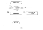
- the HMD operation unit 17 determines whether or not the current operation mode can be continued. For example, the HMD driving unit 17 determines that the current driving mode can be continued when the vehicle 10 has not failed, and can continue the current driving mode when the vehicle 10 has some trouble. Judge that it is not.
- the HMD operation unit 17 determines in S410 that the current operation mode can be continued, the HMD operation unit 17 shifts to S420, sets to continue the automatic mode, and returns to S410.
- the HMD operation unit 17 shifts to S430, changes the operation mode according to the logical table, and then ends the automatic mode processing of FIG. 7.
- each input item includes the presence or absence of qualification using HMD30, the intention of the driver, the state of the driver, the driving mode before the transition, the result of the vehicle driving system abnormality diagnosis, and the abnormality of the HMD device.
- the * mark in the logical table indicates that the state is arbitrary.
- Whether or not you are qualified to use the HMD30 is "Yes (inside the car)" when the in-vehicle HMD is enabled, and “Yes (outside the car)” when the outside HMD is enabled. If it does not correspond to, it becomes “None”.
- the driver's intention is an item in which the driver selects in advance what kind of driving mode he / she desires to drive. As the driver's state, the contents detected by the above-mentioned S140, S170, S200, and the later-described S470 are adopted.
- the vehicle running system abnormality diagnosis result indicates the failure state of the vehicle 10, in other words, it is information that associates the part of the vehicle 10 with the presence or absence of the failure.
- the "vehicle running state acquisition system” and the “vehicle pseudo operation system” are input systems indispensable for HMD operation.
- the "vehicle running state acquisition system” is configured by a communication unit 19 or the like for acquiring information obtained from sensors 21 such as vehicle speed inside the vehicle 10.
- the "vehicle simulated operation system” is a configuration of a communication unit 19 for acquiring information on an operation obtained from the controller 50 from the outside of the vehicle 10, a communication unit 59 of the controller 50, and the like.
- the logical table shown in FIG. 8 is set based on the following concept.
- manual driving there are three modes of manual driving, conventional manual mode, in-vehicle HMD mode (that is, in-vehicle HMD driving), and out-of-vehicle HMD mode (that is, out-of-vehicle HMD driving).
- in-vehicle HMD mode that is, in-vehicle HMD driving
- out-of-vehicle HMD mode that is, out-of-vehicle HMD driving
- the priority setting may be changed in a direction that can ensure more safety due to future advances in laws and technology.
- the "control judgment system” is a function that controls safety such as automatic braking. If an abnormality occurs in the "control judgment system", the automatic mode, the in-vehicle HMD mode, and the out-of-vehicle HMD mode are not selected. In this case, if the system is responsible for the driver, it will be in the same state as a conventional vehicle that cannot be automatically driven.
- the driver and the driving mode can be selected when the ignition is turned on. Further, in the vehicle driving system 1, it is possible for the driver to change during one trip from the ignition ON to the ignition OFF.
- the default driver selection when the ignition is ON is to give priority to the qualified driver in the vehicle, but if there is no qualified driver in the vehicle, the HMD driver outside the vehicle can remotely turn the ignition ON. Is.
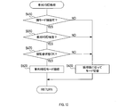
- the HMD operation unit 17 determines in S410 that the current operation mode cannot be continued, the HMD operation unit 17 shifts to S430.
- the HMD driving unit 17 determines that the current mode can be continued in S410, the HMD driving unit 17 shifts to S460, and the HMD driving unit 17 determines whether or not the in-vehicle HMD is effective.
- the HMD driving unit 17 determines in S460 that the in-vehicle HMD is not effective, the HMD driving unit 17 shifts to S430.
- the HMD driving unit 17 determines in S460 that the in-vehicle HMD is effective, the HMD driving unit 17 shifts to S470 and determines whether or not the driver's condition is good. The driver status is determined by the driver monitoring unit 36. When the HMD operation unit 17 determines in S470 that the driver's condition is not good, the HMD operation unit 17 shifts to S430.
- the HMD driving unit 17 determines in S470 that the driver's condition is good, the HMD driving unit 17 shifts to S480, sets to continue the in-vehicle HMD mode, and ends the in-vehicle HMD processing of FIG.
- the HMD driving unit 17 ends the in-vehicle HMD processing of FIG. 9 after changing the driving mode according to the logical table in the same manner as the automatic mode processing.
- the HMD operation unit 17 determines in S410 that the current operation mode cannot be continued, the HMD operation unit 17 shifts to S430.
- the HMD driving unit 17 determines that the current mode can be continued in S410, the HMD driving unit 17 shifts to S510, and the HMD driving unit 17 determines whether or not the HMD outside the vehicle is effective.
- the HMD driving unit 17 determines in S510 that the HMD outside the vehicle is not effective, the HMD driving unit 17 shifts to S430.
- the HMD driving unit 17 determines in S510 that the HMD outside the vehicle is effective, the HMD driving unit 17 shifts to S470 and determines whether or not the driver's condition is good. The driver status is determined by the driver monitoring unit 36. When the HMD operation unit 17 determines in S470 that the driver's condition is not good, the HMD operation unit 17 shifts to S430.
- the HMD driving unit 17 determines in S470 that the driver's condition is good, the HMD driving unit 17 shifts to S520, sets to continue the out-of-vehicle HMD mode, and ends the out-of-vehicle HMD processing of FIG.
- the HMD driving unit 17 ends the out-of-vehicle HMD processing of FIG. 10 after changing the mode according to the logical table in the same manner as the automatic mode processing.
- the HMD operation unit 17 determines in S410 that the current mode cannot be continued, the HMD operation unit 17 shifts to S590.
- the HMD operation unit 17 determines in S410 that the current mode can be continued, it shifts to S560 and determines whether or not the conventional manual operation is effective. When the HMD operation unit 17 determines in S560 that the conventional manual operation is not effective, the HMD operation unit 17 shifts to S590.
- the HMD operation unit 17 determines in S560 that the conventional manual operation is effective, the HMD operation unit 17 shifts to S570 and determines whether or not the driver's condition is good.
- the HMD operation unit 17 determines in S570 that the driver's condition is good, the HMD operation unit 17 shifts to S580, sets to continue the conventional manual mode, and ends the conventional manual process of FIG.
- the HMD driving unit 17 determines in S570 that the driver's condition is not good, the HMD driving unit 17 shifts to S590 and automatically stops the vehicle. Alternatively, set to change the mode according to the logical table. After that, the conventional manual process of FIG. 11 is terminated.
- a vehicle driving system 1 which includes at least one wireless communication device and a vehicle 10.
- the wireless communication device includes an HMD 30 and a controller 50.
- the wireless communication device is owned by the driver.
- the vehicle 10 is capable of automatic driving and manual driving, and is configured to be capable of performing manual driving according to a command from a wireless communication device. Further, the vehicle 10 includes at least one camera unit 25, sensors 21, an information transmission unit 17A, and a driving control unit 17B.
- the camera unit 25 is configured to capture at least the traveling direction side of the vehicle 10.
- the sensors 21 are configured to detect the traveling information of the vehicle 10.
- the information transmission unit 17A is configured to transmit the image captured by the camera unit 25 and the traveling information to the HMD 30 when the manual operation is performed.
- the operation control unit 17B is configured to perform acceleration / deceleration control and steering control of the vehicle 10 in response to an operation command from the controller 50 when performing manual operation.
- the wireless communication device includes an information acquisition unit 35, a display control unit 37A, an operation reception unit 57A, and a command transmission unit 57B.
- the information acquisition unit 35 is configured to acquire the captured image and the traveling information from the vehicle 10.
- the display control unit 37A is configured to display the captured image and the image based on the traveling information on the display unit 42.
- the operation reception unit 57A is configured to receive a driving operation related to acceleration / deceleration control and steering control of the vehicle 10 by a driver who operates a wireless communication device.
- the command transmission unit 57B is configured to transmit a command based on the driving operation to the vehicle 10 as a driving command.
- the vehicle 10 can be manually driven by operating the HMD 30 and the controller 50 regardless of the position of the wireless communication device. Therefore, the degree of freedom in the configuration of the vehicle 10 can be improved.
- the wireless communication device further includes a controller 50 and an HMD 30.
- the controller 50 includes an operation receiving unit 57A and a command transmitting unit 57B.
- the HMD 30 is an HMD 30 that is separated from the controller 50 and can be attached to the driver's head, and includes an information acquisition unit 35, a display unit 42, and a display control unit 37A.
- the viewing angle at which the information necessary for driving is displayed can be widened, so that the driver can more safely recognize the situation around the vehicle 10.
- the HMD 30 further comprises a movement detection unit 37B configured to detect the movement of the driver's head.
- the display control unit 37A generates a display image with the driver's seat of the vehicle 10 as a viewpoint, and changes the display range of the display image so as to follow the movement of the head detected by the movement detection unit 37B.
- the image captured by the camera unit 25 is coordinate-converted into an image with the driver's seat as the viewpoint to generate a display image, so that the driver seems to be seated in the driver's seat of the vehicle 10.
- the image can be visually recognized. Further, since the display image that follows the movement of the driver's head is generated, the display image in the direction that the driver wants to see can be provided, and the driver can easily confirm the safety around the vehicle 10. Can be done.
- the seat position acquisition unit 17F is configured to acquire driver's seat information for specifying the position of the driver's seat of the vehicle 10.
- the display control unit 37A is configured to generate a display image with the position specified by the driver's seat information as a viewpoint.
- the position of the driver's seat of the right-hand drive vehicle, the position of the driver's seat of the left-hand drive vehicle, or the optimum position of the driver's seat for driving according to the traffic classification is acquired as driver's seat information. It is possible to provide a display image with the position as a viewpoint. Therefore, the driver can drive the vehicle 10 more safely.
- the driving mode for performing manual driving using the HMD 30 and the controller 50 is set to the first manual mode (in-vehicle HMD mode and external HMD mode), and the vehicle 10 is equipped with the HMD 30 and the controller.
- a second manual mode (conventional manual mode), which is an operation mode for manually driving the vehicle 10 without using the 50, is prepared.
- the mode selection unit 17G is selected from a plurality of operation modes including the first manual mode and the second manual mode when performing manual operation according to the failure state of the vehicle 10 and the intention of the occupant of the vehicle 10. It is configured to select the operation mode of.
- the optimum driving mode can be selected from a plurality of driving modes for manual driving according to the failure state of the vehicle 10 and the intention of the occupant of the vehicle 10.
- the suitability determination unit 17C is configured to determine whether or not the driver is suitable for driving the vehicle 10.
- the control prohibition unit 17D is configured to prohibit acceleration / deceleration control and steering control of the vehicle 10 by the operation control unit 17B when the driver determines that the vehicle is not suitable for driving.
- the suitability determination unit 17C determines whether or not the driver is intoxicated.
- the suitability determination unit 17C determines whether or not the driver has a license to drive the vehicle 10.
- the information storage unit 17E is configured to store information that identifies the driver in a preset recording unit.
- the camera unit 25 includes cameras S1, S3, S4, S5, S7 and cameras S2, S6.
- the cameras S1, S3, S4, S5, and S7 are configured to perform sensing by the first sensing method.
- the cameras S2 and S6 are configured to perform imaging by a second sensing method different from the first sensing method.
- the display control unit 37A switches at least one of the images captured by the cameras S1, S3, S4, S5 and S7 and the images captured by the cameras S2 and S6 in response to an external command and displays them on the display unit 42.
- the display control unit 37A has a specific image representing a preset type of image as an image that hinders the driving operation when the operation receiving unit 57A is in a state of accepting the driving operation. It is possible to prohibit the display on the display unit 42 and allow the specific image to be displayed on the display unit 42 when the operation reception unit 57A is in a state of not accepting the driving operation.
- the display unit 42 it is possible to prevent the display unit 42 from displaying an image that hinders the driving operation during the driving operation, so that the driver can perform the driving operation more safely. Further, at times other than the driving operation, the display unit 42 can be used to display an arbitrary image other than the driving operation.
- the second embodiment is different from the first embodiment in that it is possible to deal with the case where the communication state is not good on the premise that the communication state may not be good.
- the vehicle driving system 2 of the second embodiment includes a communication diagnosis unit 80A in the vehicle 10 in addition to the vehicle driving system 1 of the first embodiment.
- the communication diagnosis unit 80A has a function of diagnosing the communication state between the vehicle 10 and the HMD 30 and the communication state between the vehicle 10 and the controller 50. These communication states are diagnosed by the communication quality diagnosis process shown below.
- the communication state between the vehicle 10 and the controller 50 can be realized by replacing the communication partner of the process of diagnosing the communication state between the vehicle 10 and the HMD 30 from the HMD 30 with the controller 50.
- the vehicle 10 is the first device in the present disclosure
- the HMD 30 or the controller 50 is the second device in the present disclosure.
- the second apparatus is configured to return the test data as it is to the first apparatus when it receives the test data prepared in advance from the first apparatus.
- the test data the test image data which is the image captured by the camera unit 25 is used.
- the communication diagnosis unit 80A includes an image acquisition unit 86A, an image transmission / reception unit 86B, a communication determination unit 86C, a control notification unit 86D, and a use prohibition unit 86E, as shown in FIG. , Equipped with.
- Each unit 86A to 86E constituting the communication diagnosis unit 80A will be described later.
- the quality diagnosis process is a process that is started at an arbitrary timing, such as immediately before the execution of the operation setting process, before the execution of the manual operation, or during the execution of the manual operation.
- the image acquisition unit 86A acquires an image captured by the camera unit 25.
- the data transmission unit 86B uses the captured image obtained from the camera unit 25 as the test image data, and transfers the test image data to the communication partner in the air.
- Blank transfer means transmitting test image data together with a request to the communication partner to return the received data as it is.
- the HMD 30 when the vehicle 10 transmits the test image data to the HMD 30, the HMD 30 returns the received test image data to the vehicle 10 as it is.
- the data transmission unit 86B holds the transmission time of the test image data in the memory 13.
- the communication determination unit 86C determines in S630 whether or not there is a response of the test image data. If there is no response from the test image data, the process returns to S630. Further, if there is a response of the test image data, this process shifts to S640, and the communication determination unit 86C compares the test image data transmitted by the vehicle 10 with the test image data returned by the HMD 30. Here, the communication determination unit 86C calculates how much the test image data transmitted by the vehicle 10 and the test image data received by the vehicle 10 match, in other words, the consistency of the test image data. If the consistency of the test image data is low, it means that the test image data is destroyed in the process of communication.
- the communication determination unit 86C sets the vehicle 10 and the HMD 30 based on the consistency of the test image data and the delay time from the transmission of the test data by the vehicle 10 to the reception of the test image data from the HMD 30. It is determined whether or not the communication state between the two is good.
- the degree of data matching is equal to or more than a threshold value (for example, 99.9%)
- a threshold value for example, 99.9%
- the delay time for example, if the time from the transmission of the test image data by the vehicle 10 to the reception of the data is less than the threshold value (for example, 10 ms), it is determined that the communication state is good, and the delay time is equal to or more than the threshold value. If there is, it is judged that the communication state is not good.
- the threshold value for example, 10 ms
- the communication determination unit 86C determines that the communication state is good as a whole when the communication state is good in terms of both the consistency and the delay time of the test image data. Further, the communication determination unit 86C determines that the communication state is not good as a whole when the communication state is not good due to the consistency or delay time of the test image data.
- this process ends. Further, if the communication state is not good in S650, this process shifts to S660, and the control notification unit 86D indicates that the HMD operation system cannot be used by the driver operating the HMD 30, that is, the operation control unit 17B. Notifies that acceleration / deceleration control and steering control of the vehicle 10 are prohibited.
- This notification is performed by transmitting information such as an image, character information, and voice to at least one of the HMD 30 and the controller 50.
- the HMD 30 and the controller 50 receive information such as an image, character information, and voice
- the HMD 30 and the controller 50 output the received information to the driver using a display, a speaker, or the like.
- the use prohibition unit 86E is set to prohibit the acceleration / deceleration control and steering control of the vehicle 10 by the operation control unit 17B.
- the HMD valid setting is canceled and the HMD 30 is set so as not to be used.
- one of the HMD 30 (or controller 50) and the vehicle 10 is the first device, and the other of the HMD 30 (or controller 50) and the vehicle 10 is the second device.
- the vehicle driving system 2 of the second embodiment includes a data receiving unit 86B, a communication determination unit 86C, and a use prohibition unit 86E.
- the data receiving unit 86B is arranged in the first device and is configured to receive test data prepared in advance from the second device before or during the manual operation.
- the communication determination unit 86C is configured to determine whether or not the communication state between the first device and the second device is good according to the reception state of the test data.
- the use prohibition unit 86E is configured to prohibit acceleration / deceleration control and steering control of the vehicle 10 by the operation control unit 17B when the communication determination unit 86C determines that the communication state is not good.
- acceleration / deceleration control and steering control of the vehicle 10 by the operation control unit 17B are prohibited when the communication state is not good. Therefore, while the operation control unit 17B is controlling the vehicle 10, the vehicle is interrupted due to communication interruption. It is possible to prevent the 10 from becoming out of control.
- the second device is configured to return the test data as it is to the first device when receiving the test data prepared in advance from the first device.
- the vehicle driving system 2 further includes a data transmission unit 86B, which is arranged in the first device and is configured to transmit test data to the second device.
- the communication determination unit 86C receives the test data from the second device after the first device transmits the test data and the consistency between the test data transmitted by the first device and the test data returned by the second device. It is configured to determine whether or not the communication state between the first device and the second device is good based on at least one of the delay times until the first device and the second device.
- the communication status is determined using the consistency between the transmitted test data and the returned test data and the delay time, so that the communication status can be determined more accurately than the configuration in which the test data is simply received. Can be determined.
- the first apparatus further includes an image acquisition unit 86A.
- the image acquisition unit 86A is configured to acquire images captured by the camera units 25, 81B, 81C.
- the data transmission unit 86B is configured to transmit image data including a captured image as test data.
- the suitability determination unit 17C of the vehicle 10 determines whether or not the driver is suitable for driving the vehicle 10, but the present invention is not limited to this configuration.
- the HMD 30, the controller 50, another server, or the like may determine whether the driver is suitable for driving the vehicle 10.
- license authentication it is possible to detect sitting in the designated driver's seat and warn if it is not seated.
- the driver's seating position may be freely set and the certification may be performed only once.
- license authentication may be performed by communication with an external server.
- the information storage unit 17E of the vehicle 10 is configured to record a log, but the present invention is not limited to this.
- the server 70, the HMD 30 or the like may be provided with an information storage unit 17E to record a log.
- the vehicle 10 is provided with a driver's seat having an accelerator 22, a brake 23, and a steering wheel 24, but the vehicle 10 does not have to be provided with a driver's seat.
- a part of the image obtained by combining the captured images of the plurality of cameras S1 to S7 is generated as a display image, but the cameras S1 to S7 themselves have a movable structure and the head of the driver wearing the HMD30.
- the directions of the cameras S1 to S7 may be linked according to the movement of the camera.
- the camera unit 25 may have a telephoto function and a local enlargement function.
- the telephoto function and the local enlargement function can be selected in the display image displayed by the HMD 30.
- a part of the peripheral monitoring sensor may be mounted on the HMD30.
- the vehicle 10 may acquire the detection result of the peripheral monitoring sensor from the HMD 30.
- the HMD 30 and the controller 50 can be used for purposes other than communication with the vehicle 10.
- the HMD 30 and the controller 50 can function as a medical device by communicating with a local robot located at a remote location.
- the HMD 30 and the controller 50 can be used when driving and operating a moving body other than the vehicle 10.
- the controller 50 may be configured to be able to operate the winker, wiper, etc. in the vehicle 10.
- the HMD 30 and the controller 50 are configured as separate wireless communication terminals capable of communicating with the vehicle 10, respectively, but may be integrally configured as a wireless communication device such as a tablet terminal or the like.
- Switching the front seat driver's viewpoint of a qualified driver during HMD driving may be fixed from the default value, or may be switched at the will of the qualified driver.
- the system authentication of the HMD operation license may be performed by the host server via the network system outside the vehicle by the wireless communication means such as 5G built in the HMD30, the navigation system or the like.
- the mode of driving with an HMD driving license in an automatic driving vehicle does not necessarily require a qualified driver to be seated in a specific driver's seat before starting the vehicle, and after the system certification of the HMD driving license, the vehicle is inside the vehicle. -If you are seated outside, you may be able to switch from automatic operation to HMD operation at any time.
- a virtual operation means is projected in the HMD, and the driving operation intention of a qualified driver by joystick, voice recognition, gesture recognition, etc. (That is, a means for associating a means for transmitting the above (that is, a simulated operation operation system) may be provided.
- the input device of the simulated operation operation system may be attached to the HMD main body by wire, or may have a separate structure constructed by a system such as wireless communication or infrared communication.
- a visible light camera is usually used as a sensor information source for a real image, but in order to improve visibility at night, etc., from another sensor information such as an infrared ray, a spectrum camera, or a lidar, the inside of the device or
- the image processed in the cloud may be displayed on a partial screen or a full screen in the HMD device according to the driver's choice.
- a means for optimally selecting a sensor of a peripheral monitoring sensor group mounted on a vehicle may be provided, and a plurality of real images or extended images or a composite image of both images may be provided to the HMD driver. ..
- the driver may be able to select any image such as a real image, an augmented reality image, a mixed reality image, and a virtual reality image.
- the driver can select whether to display a composite image without blind spots with at least one of the vehicle body, seats, and passenger's body removed, or an incomplete recognition target (eg, an incomplete recognition target).
- an incomplete recognition target eg, an incomplete recognition target
- the (5k) HMD 30 may be a transmissive HMD.
- a conventional manual driver may wear the transmissive HMD as a driving information auxiliary display device and operate the driving using pedals such as the accelerator 22.
- the authentication unit 72 of the server 70 may hold a list of inoperable persons prepared in advance.
- the non-driving person list contains information on people who should not be driven. Persons who should not be driven may include multiple persons of interest, such as terrorists, criminals, and infectious disease carriers.
- the HMD driving unit 17 cannot drive the authenticated driver when determining whether or not the authenticated driver is in the vehicle 10. It is good to include people who need attention on the person list.
- the HMD operation unit 17 determines in S140, S170, and S200 whether or not the authentication is good and whether or not the driver's drunkenness is good, when the authentication is not good. , The case where the driver is a person who needs attention should be included. In this case, if the HMD driving unit 17 determines in any of S140, S170, and S200 that the driver is a person requiring attention or the degree of drunkenness is not good, the HMD driving unit 17 may shift to S260.
- the communication state is determined by exchanging test image data, but the configuration is not limited to this.
- the vehicle 10 may receive the test data prepared in advance from the HMD 30 or the controller 50 without transmitting the test image data, or the HMD 30 or the controller 50 may use arbitrary data other than the captured image in place of the test image data. May be sent to.
- the vehicle 10 is provided with the communication diagnosis unit 80A, and the vehicle 10 diagnoses the communication state, but the configuration is not limited to this.
- the HMD 30 or the controller 50 may be provided with the communication diagnosis unit 80B or 80C.
- the communication diagnosis unit 80B is provided in the HMD 30
- the camera unit 81B may be provided in the HMD 30.
- the HMD 30 may execute the communication quality diagnosis process with the vehicle 10 and the controller 50 as communication partners.
- the controller 50 when the controller 50 is provided with the communication diagnosis unit 80C, the controller 50 may be provided with the camera unit 81C. In this configuration, in this configuration, the HMD 30 may execute the communication quality diagnosis process with the vehicle 10 and the HMD 30 as communication partners.
- a plurality of functions possessed by one component in the above embodiment may be realized by a plurality of components, or one function possessed by one component may be realized by a plurality of components. .. Further, a plurality of functions possessed by the plurality of components may be realized by one component, or one function realized by the plurality of components may be realized by one component. Further, a part of the configuration of the above embodiment may be omitted. In addition, at least a part of the configuration of the above embodiment may be added or replaced with the configuration of the other above embodiment.
- a vehicle 10 and a wireless communication device which are components of the vehicle driving system 1, a program for operating a computer as a component of the vehicle driving system 1, and this program are recorded.
- the present disclosure can also be realized in various forms such as a non-transitional actual recording medium such as a semiconductor memory, a remote operation method of a vehicle, and the like.
Abstract
In one mode of the present disclosure, a controlled vehicle comprises: an information transmission unit (17A) configured to transmit, to a wireless communication device, a sensing image based on the result of sensing performed by a sensing unit and travel information when implementing manual driving; and a driving control unit (17B) configured to implement acceleration/deceleration control and steering control of the controlled vehicle according to driving commands from the wireless communication device when implementing manual driving, the wireless communication device being provided with an operation-receiving unit (57A) configured to receive a driving operation pertaining to acceleration/deceleration control and steering control of the controlled vehicle by the driver operating the wireless communication device, and a command transmission unit (57B) that transmits commands based on the driving operation as driving commands to the controlled vehicle.
Description
本国際出願は、2019年12月6日に日本国特許庁に出願された日本国特許出願第2019-221238号に基づく優先権を主張するものであり、日本国特許出願第2019-221238号の全内容を本国際出願に参照により援用する。
This international application claims priority based on Japanese Patent Application No. 2019-22138 filed with the Japan Patent Office on December 6, 2019, and Japanese Patent Application No. 2019-22138. The entire contents are incorporated in this international application by reference.
本開示は、被制御車両と無線通信装置とを備える車両運転システムに関する。
The present disclosure relates to a vehicle driving system including a controlled vehicle and a wireless communication device.
例えば、下記特許文献1には、手動運転中の運転者が急病になった場合等に、助手席等の乗員が運転者の代わりに緊急運転ができるようにする技術が提案されている。
For example, Patent Document 1 below proposes a technique that enables a occupant in the passenger seat or the like to perform emergency driving on behalf of the driver when the driver during manual driving suddenly becomes ill.
ところで、近年、自動運転車両が開発されている。現状の自動運転車両は、状況によって手動運転に切り替える必要がある。発明者の詳細な検討の結果、現状の自動運転車両は自動運転レベルによっては、必ず運転者が運転席に着座する必要があり、自動運転車両での乗員の移動の自由度や、ハンドル、ペダル類の配置等の構成に制約があるという課題が見出された。
By the way, in recent years, self-driving vehicles have been developed. The current self-driving vehicle needs to be switched to manual driving depending on the situation. As a result of detailed examination by the inventor, the current autonomous driving vehicle requires the driver to be seated in the driver's seat depending on the autonomous driving level, and the degree of freedom of movement of the occupants in the autonomous driving vehicle, the handle, and the pedal. The problem was found that there are restrictions on the composition such as the arrangement of types.
本開示の1つの局面は、自動運転車両の手動運転に運転者が対応できるようにしつつ、自動運転車両の構成の自由度を向上できるようにすることにある。
One aspect of the present disclosure is to enable the driver to cope with the manual driving of the autonomous driving vehicle and to improve the degree of freedom in the configuration of the autonomous driving vehicle.
本開示の一態様は、車両運転システムであって、少なくとも1つの無線通信装置と、被制御車両と、を備える。無線通信装置は、運転者が所持する。被制御車両は、自動運転及び手動運転が可能であり、無線通信装置からの指令による手動運転を実施可能に構成される。また、被制御車両は、少なくとも1つのセンシング部と、情報検知部と、情報送信部と、運転制御部と、を備える。
One aspect of the present disclosure is a vehicle driving system, comprising at least one wireless communication device and a controlled vehicle. The wireless communication device is owned by the driver. The controlled vehicle can be automatically driven and manually driven, and can be manually driven by a command from a wireless communication device. Further, the controlled vehicle includes at least one sensing unit, an information detecting unit, an information transmitting unit, and a driving control unit.
センシング部は、当該被制御車両における少なくとも進行方向側をセンシングするように構成される。情報検知部は、当該被制御車両の走行情報を検知するように構成される。情報送信部は、手動運転を実施する際に、センシング部によるセンシング結果に基づくセンシング画像、及び走行情報を無線通信装置に送信するように構成される。運転制御部は、手動運転を実施する際に、無線通信装置からの運転指令に応じて、当該被制御車両の加減速制御及び操舵制御を実施するように構成される。
The sensing unit is configured to sense at least the traveling direction side of the controlled vehicle. The information detection unit is configured to detect the traveling information of the controlled vehicle. The information transmission unit is configured to transmit a sensing image based on the sensing result by the sensing unit and driving information to the wireless communication device when the manual operation is performed. The operation control unit is configured to perform acceleration / deceleration control and steering control of the controlled vehicle in response to an operation command from the wireless communication device when performing manual operation.
無線通信装置は、情報取得部と、表示制御部と、操作受付部と、指令送信部と、を備える。情報取得部は、センシング画像及び走行情報を被制御車両から取得するように構成される。表示制御部は、センシング画像及び走行情報に基づく画像を表示部に表示させるように構成される。操作受付部は、当該無線通信装置を操作する運転者による、当該被制御車両の加減速制御及び操舵制御に関する運転操作を受け付けるように構成される。指令送信部は、運転操作に基づく指令を運転指令として被制御車両に送信するように構成される。
The wireless communication device includes an information acquisition unit, a display control unit, an operation reception unit, and a command transmission unit. The information acquisition unit is configured to acquire sensing images and traveling information from the controlled vehicle. The display control unit is configured to display a sensing image and an image based on driving information on the display unit. The operation reception unit is configured to receive driving operations related to acceleration / deceleration control and steering control of the controlled vehicle by the driver who operates the wireless communication device. The command transmitting unit is configured to transmit a command based on the driving operation as a driving command to the controlled vehicle.
このような構成によれば、被制御車両と無線通信装置とが通信可能であれば、無線通信装置の位置によらず、無線通信装置への操作により被制御車両を手動運転することが可能となり、被制御車両の構成の自由度を向上させることができる。
According to such a configuration, if the controlled vehicle and the wireless communication device can communicate with each other, the controlled vehicle can be manually driven by operating the wireless communication device regardless of the position of the wireless communication device. , The degree of freedom in the configuration of the controlled vehicle can be improved.
以下、図面を参照しながら、本開示の第1実施形態を説明する。
Hereinafter, the first embodiment of the present disclosure will be described with reference to the drawings.
[1.概要]
初めに、本開示の概要を説明する。従来、自動車では、特定の運転資格を有する運転者の席が、安全な手動運転を担保できる場所(すなわち運転席)として限定されていた。今後、自動車においても自動運転が普及して行く段階で、運転席を限定しない車両構造になって行くことも予測される。そこで、本開示では、自動運転システムの異常やシステムの性能限界等を理由として、手動運転に切り替える場合に、運転者の位置を限定しない「HMD運転操作システム」である、車両運転システム1を提供する。HMD30は、頭部装着型表示装置である。HMD30は、例えば、ゴーグル型、フルフェイスヘルメット型等、概ね使用者の視野の全域を表示部で覆うことができる形状であれば任意の形状を採用できる。 [1. Overview]
First, the outline of the present disclosure will be described. Conventionally, in automobiles, the seats of drivers with specific driving qualifications have been limited as places where safe manual driving can be guaranteed (that is, driver's seats). In the future, as autonomous driving becomes more widespread in automobiles, it is expected that the vehicle structure will not limit the driver's seat. Therefore, the present disclosure provides avehicle driving system 1, which is an "HMD driving operation system" that does not limit the position of the driver when switching to manual driving due to an abnormality in the automatic driving system, a performance limit of the system, or the like. To do. The HMD 30 is a head-mounted display device. The HMD 30 can adopt any shape as long as it can cover the entire field of view of the user with the display unit, such as a goggle type and a full-face helmet type.
初めに、本開示の概要を説明する。従来、自動車では、特定の運転資格を有する運転者の席が、安全な手動運転を担保できる場所(すなわち運転席)として限定されていた。今後、自動車においても自動運転が普及して行く段階で、運転席を限定しない車両構造になって行くことも予測される。そこで、本開示では、自動運転システムの異常やシステムの性能限界等を理由として、手動運転に切り替える場合に、運転者の位置を限定しない「HMD運転操作システム」である、車両運転システム1を提供する。HMD30は、頭部装着型表示装置である。HMD30は、例えば、ゴーグル型、フルフェイスヘルメット型等、概ね使用者の視野の全域を表示部で覆うことができる形状であれば任意の形状を採用できる。 [1. Overview]
First, the outline of the present disclosure will be described. Conventionally, in automobiles, the seats of drivers with specific driving qualifications have been limited as places where safe manual driving can be guaranteed (that is, driver's seats). In the future, as autonomous driving becomes more widespread in automobiles, it is expected that the vehicle structure will not limit the driver's seat. Therefore, the present disclosure provides a
車両運転システム1は、システム責任下での自動運転の継続が困難となったとき、自動運転の継続が困難になると予測されたとき、又は、運転者の意志によって、HMD30を用いた手動運転が実施される。HMD30を用いた手動運転では、HMD30を頭部に装着し、コントローラ50で運転操作する手動運転を許可された運転ライセンスを持った人へ、最低限運転に必要な視界情報を提供することで、コントローラ50を利用した安全な運転操作を確保する。
In the vehicle driving system 1, when it becomes difficult to continue automatic driving under the responsibility of the system, when it is predicted that it will be difficult to continue automatic driving, or by the driver's will, manual driving using HMD30 is performed. Will be implemented. In manual driving using the HMD30, the HMD30 is attached to the head and the controller 50 is used to operate the driver. By providing the minimum visibility information necessary for driving to a person who has a driving license and is permitted to perform the manual driving. Ensure safe driving operation using the controller 50.
車両運転システム1では、運転ライセンスを有する運転者の位置に限定されることなく、運転者が、車内のいずれかの席、或いは車外にいる場合であっても、自動運転状態と手動運転状態とを双方向で安全に移行することができる。
In the vehicle driving system 1, the driver is not limited to the position of the driver who has a driving license, and even if the driver is in any seat in the vehicle or outside the vehicle, the automatic driving state and the manual driving state can be obtained. Can be safely migrated in both directions.
ここで、現状の運転者責任が残る自動運転レベルのシステムでは、システムから運転者へ運転交替を要求したときに、運転者への正常な運転交替が担保できないと判断したときは、車両を一旦、安全に自動停車させることが必須となっている。しかし、本開示によれば、適切な運転者が車両内外を問わず存在すれば、車両を停車させることなく、HMD30を頭部に装着しHMIツールで運転操作する手動運転に切り替えることが可能である。
Here, in an automatic driving level system in which the current driver's responsibility remains, when the system requests the driver to change driving, and if it is determined that the normal driving change to the driver cannot be guaranteed, the vehicle is temporarily moved. , It is essential to stop the vehicle safely and automatically. However, according to the present disclosure, if an appropriate driver exists both inside and outside the vehicle, it is possible to switch to manual driving in which the HMD30 is mounted on the head and operated by the HMI tool without stopping the vehicle. is there.
本開示の車両運転システム1は、有資格運転者が車両内外のどこに着座していても、車両周辺のカメラ部25から適切に選択した1つまたは複数の画像から視点変換して合成し、HMD30内に投影することにより、あたかも有資格運転者が、従来の運転席に着座しているかのような視野で運転をすることが可能である。
The vehicle driving system 1 of the present disclosure converts the viewpoint from one or a plurality of images appropriately selected from the camera unit 25 around the vehicle and synthesizes the HMD 30 regardless of where the qualified driver is seated inside or outside the vehicle. By projecting inside, it is possible for a qualified driver to drive with a view as if he / she is seated in a conventional driver's seat.
[2.本実施形態の構成と本開示の構成との対応関係]
本実施形態におけるHMD30及びコントローラ50は、本開示での無線通信装置に相当し、本実施形態における車両10は、本開示での被制御車両に相当する。また、本実施形態におけるカメラ部25は、本開示での撮像部に相当し、本実施形態におけるS1,S3,S4,S5,S7は、本開示での第1撮像部に相当し、本実施形態におけるS2,S6は、本開示での第2撮像部に相当する。また、本実施形態におけるセンサ類21は、本開示での情報検知部に相当する。 [2. Correspondence between the configuration of the present embodiment and the configuration of the present disclosure]
TheHMD 30 and the controller 50 in the present embodiment correspond to the wireless communication device in the present disclosure, and the vehicle 10 in the present embodiment corresponds to the controlled vehicle in the present disclosure. Further, the camera unit 25 in the present embodiment corresponds to the imaging unit in the present disclosure, and S1, S3, S4, S5, S7 in the present embodiment correspond to the first imaging unit in the present disclosure. S2 and S6 in the embodiment correspond to the second imaging unit in the present disclosure. Further, the sensors 21 in the present embodiment correspond to the information detection unit in the present disclosure.
本実施形態におけるHMD30及びコントローラ50は、本開示での無線通信装置に相当し、本実施形態における車両10は、本開示での被制御車両に相当する。また、本実施形態におけるカメラ部25は、本開示での撮像部に相当し、本実施形態におけるS1,S3,S4,S5,S7は、本開示での第1撮像部に相当し、本実施形態におけるS2,S6は、本開示での第2撮像部に相当する。また、本実施形態におけるセンサ類21は、本開示での情報検知部に相当する。 [2. Correspondence between the configuration of the present embodiment and the configuration of the present disclosure]
The
[3.実施形態]
上記概要の詳細を以下に説明する。 [3. Embodiment]
The details of the above outline will be described below.
上記概要の詳細を以下に説明する。 [3. Embodiment]
The details of the above outline will be described below.
[3-1.ハードウェア構成]
図1に示す車両運転システム1は、車両10と、頭部装着型表示装置(以下、HMD)30と、コントローラ50と、を備える。また、車両運転システム1は、サーバ70を備えてもよい。 [3-1. Hardware configuration]
Thevehicle driving system 1 shown in FIG. 1 includes a vehicle 10, a head-mounted display device (hereinafter, HMD) 30, and a controller 50. Further, the vehicle driving system 1 may include a server 70.
図1に示す車両運転システム1は、車両10と、頭部装着型表示装置(以下、HMD)30と、コントローラ50と、を備える。また、車両運転システム1は、サーバ70を備えてもよい。 [3-1. Hardware configuration]
The
車両10は、自動運転及び手動運転が可能であり、手動運転のモードの一部として、無線通信装置からの指令による手動運転を実施可能に構成される。本実施形態では、HMD30及びコントローラ50が無線通信装置に該当する。車両10は、運転者責任のない自動運転を実施可能である。運転者責任のない自動運転とは、システム異常時に、従来運転者へ運転交替を強要しない自動運転であることを示す。
The vehicle 10 is capable of automatic driving and manual driving, and is configured to be capable of performing manual driving by a command from a wireless communication device as a part of the manual driving mode. In this embodiment, the HMD 30 and the controller 50 correspond to a wireless communication device. The vehicle 10 can carry out automatic driving without driver responsibility. Autonomous driving without driver responsibility means automatic driving that does not force the conventional driver to change driving in the event of a system abnormality.
したがって、車両10には運転者が搭乗する必要がない。ただし、自動運転レベルによっては、車両10の異常時等の緊急時に、車両10の運転席に運転者がいる場合、この運転者、或いは、車両10の内外にいるリモートによる運転者がいる場合、これらの運転者による運転操作を可能とする。なお、車両10の緊急時に、適切な運転者が存在しない場合、車両10は安全に停車する。また、車両10は、自動運転可能な場合においても、乗員が手動運転しようとする場合には、手動運転が実施可能である。手動運転には、後述する従来手動モード及び車内HMDモードが含まれる。
Therefore, it is not necessary for the driver to board the vehicle 10. However, depending on the automatic driving level, if there is a driver in the driver's seat of the vehicle 10 in an emergency such as an abnormality of the vehicle 10, or if there is a remote driver inside or outside the vehicle 10, the driver may be present. It enables driving operations by these drivers. In the event of an emergency of the vehicle 10, if there is no suitable driver, the vehicle 10 will stop safely. Further, even when the vehicle 10 can be automatically driven, the manual driving can be carried out when the occupant intends to manually drive the vehicle. The manual driving includes a conventional manual mode and an in-vehicle HMD mode, which will be described later.
車両10は、制御部11と、センサ類21と、アクセル22と、ブレーキ23と、ステアリング24と、カメラ部25と、被制御部26とを備える。
The vehicle 10 includes a control unit 11, sensors 21, an accelerator 22, a brake 23, a steering wheel 24, a camera unit 25, and a controlled unit 26.
センサ類21は、車両10の走行情報を検知するように構成される。走行情報は、車両10の走行に関する情報である。走行情報には車両10の車速、舵角、アクセル及びブレーキ作動状態、加速度等が含まれうる。
The sensors 21 are configured to detect the traveling information of the vehicle 10. The traveling information is information related to the traveling of the vehicle 10. The traveling information may include the vehicle speed, steering angle, accelerator and brake operating states, acceleration, and the like of the vehicle 10.
アクセル22は、車両10の運転席に配置されるアクセルペダルである。ブレーキ23は、車両10の運転席に配置されるブレーキペダルである。ステアリング24は、車両10の運転席に配置されるステアリングホイールである。これらに対する操作内容は、制御部11で認識され、制御部11は、被制御部26に対して操作内容に対応する指令を送信する。
The accelerator 22 is an accelerator pedal arranged in the driver's seat of the vehicle 10. The brake 23 is a brake pedal arranged in the driver's seat of the vehicle 10. The steering wheel 24 is a steering wheel arranged in the driver's seat of the vehicle 10. The operation contents for these are recognized by the control unit 11, and the control unit 11 transmits a command corresponding to the operation contents to the controlled unit 26.
カメラ部25は、車両10における少なくとも進行方向側を撮像するように構成される。カメラ部25の詳細については後述する。
The camera unit 25 is configured to capture at least the traveling direction side of the vehicle 10. The details of the camera unit 25 will be described later.
被制御部26は、車両10の加減速及び操舵を制御するアクチュエータとして構成される。被制御部26には、例えば、加減速を制御する走行用モータ、燃料噴射装置、ブレーキ油圧制御装置、舵角を制御する操舵用モータ等が含まれる。
The controlled unit 26 is configured as an actuator that controls acceleration / deceleration and steering of the vehicle 10. The controlled unit 26 includes, for example, a traveling motor for controlling acceleration / deceleration, a fuel injection device, a brake oil pressure control device, a steering motor for controlling a steering angle, and the like.
HMD30は、車両10と無線通信可能であり、車両10を遠隔操作するために必要な情報を画像によって運転者に提供するための装置である。HMD30は、コントローラ50と分離され、運転者の頭部に装着可能に構成され、運転者に所持される装置である。
The HMD 30 is a device capable of wirelessly communicating with the vehicle 10 and providing the driver with information necessary for remotely controlling the vehicle 10 by means of an image. The HMD 30 is a device that is separated from the controller 50, is configured to be mounted on the driver's head, and is possessed by the driver.
HMD30は、制御部31と、センサ部41と、表示部42と、を備える。センサ部41は、HMD30の位置、周囲の照度、運転者の眼球の動き、運転者の瞳における瞬きの有無、運転者の頭部の向き等を検知する機能を有する。
The HMD 30 includes a control unit 31, a sensor unit 41, and a display unit 42. The sensor unit 41 has a function of detecting the position of the HMD 30, the ambient illuminance, the movement of the driver's eyeball, the presence or absence of blinking in the driver's eyes, the orientation of the driver's head, and the like.
表示部42は、制御部31からの指令に応じた画像を表示させるディスプレイとして構成される。HMD30は、運転者の両眼を外側から運転者の視野の大部分を覆う内面を備えており、表示部42は、この内面に沿った表示面に画像を表示させる。
The display unit 42 is configured as a display that displays an image in response to a command from the control unit 31. The HMD 30 includes an inner surface that covers most of the driver's field of view from the outside with both eyes of the driver, and the display unit 42 causes the display unit 42 to display an image on the display surface along the inner surface.
コントローラ50は、車両10と無線通信可能であり、運転者が車両10を運転するための操作を受け付ける装置である。コントローラ50は、制御部51と、センサ部61と、操作部62とを備える。
The controller 50 is a device capable of wireless communication with the vehicle 10 and accepting an operation for the driver to drive the vehicle 10. The controller 50 includes a control unit 51, a sensor unit 61, and an operation unit 62.
センサ部61は、音声、運転者の指紋等を検知する機能を有する。操作部62は、一般的なコントローラに備えられる複数のボタン、スティック等のスイッチ、或いはタッチパネル等を備える。
The sensor unit 61 has a function of detecting voice, a driver's fingerprint, and the like. The operation unit 62 includes a plurality of buttons, switches such as sticks, a touch panel, and the like provided in a general controller.
車両10の制御部11、HMD30の制御部31、及びコントローラ50の制御部51は、それぞれ、CPU12,32,52と、例えば、RAM又はROM等の半導体メモリ(以下、メモリ13,33,53)と、を有するマイクロコンピュータを備える。制御部11,31,51の各機能は、CPU12,32,52が非遷移的実体的記録媒体に格納されたプログラムを実行することにより実現される。
The control unit 11 of the vehicle 10, the control unit 31 of the HMD 30, and the control unit 51 of the controller 50 are CPUs 12, 32, 52, respectively, and semiconductor memories such as RAM or ROM (hereinafter, memories 13, 33, 53). And comprises a microcomputer having. Each function of the control units 11, 31, and 51 is realized by the CPUs 12, 32, and 52 executing a program stored in the non-transitional substantive recording medium.
この例では、メモリ13,33,53が、プログラムを格納した非遷移的実体的記録媒体に該当する。また、このプログラムが実行されることで、プログラムに対応する方法が実行される。なお、非遷移的実体的記録媒体とは、記録媒体のうちの電磁波を除く意味である。また、制御部11,31,51は、1つのマイクロコンピュータを備えてもよいし、複数のマイクロコンピュータを備えてもよい。
In this example, the memories 13, 33, and 53 correspond to the non-transitional substantive recording medium in which the program is stored. Moreover, when this program is executed, the method corresponding to the program is executed. The non-transitional substantive recording medium means that electromagnetic waves are excluded from the recording medium. Further, the control units 11, 31, and 51 may include one microcomputer or a plurality of microcomputers.
制御部11,31,51は、後述する各部を備える。これら各部の機能を実現する手法はソフトウェアに限るものではなく、その一部又は全部の機能は、一つあるいは複数のハードウェアを用いて実現されてもよい。例えば、上記機能がハードウェアである電子回路によって実現される場合、その電子回路は、デジタル回路、又はアナログ回路、あるいはこれらの組合せによって実現されてもよい。
The control units 11, 31, and 51 include each unit described later. The method for realizing the functions of each of these parts is not limited to software, and some or all of the functions may be realized by using one or more hardware. For example, when the above function is realized by an electronic circuit which is hardware, the electronic circuit may be realized by a digital circuit, an analog circuit, or a combination thereof.
サーバ70は、自動運転に必要な情報、HMD30での認証に必要な情報等を車両10に提供する装置である。サーバ70は、各種情報提供部71と、認証部72とを備える。
The server 70 is a device that provides the vehicle 10 with information necessary for automatic driving, information necessary for authentication with the HMD 30, and the like. The server 70 includes various information providing units 71 and an authentication unit 72.
各種情報提供部71は、例えば、地図情報等を備えており、車両10からの要求に応じて必要なデータを車両10に提供する。認証部72は、例えば、資格を有する運転者に関する情報である資格情報が予め記録されており、車両10等の要求に応じて車両10に資格情報を提供する。
The various information providing units 71 are provided with map information and the like, and provide necessary data to the vehicle 10 in response to a request from the vehicle 10. For example, the authentication unit 72 records qualification information that is information about a qualified driver in advance, and provides the qualification information to the vehicle 10 in response to a request from the vehicle 10 or the like.
[3-2.制御部11,31,51の機能]
車両10の制御部11は、自動運転部16と、HMD運転部17と、通信部19とを備える。自動運転部16は、運転者の操作を必要としない自動運転を実施するように構成される。 [3-2. Functions of control units 11, 31, and 51]
Thecontrol unit 11 of the vehicle 10 includes an automatic driving unit 16, an HMD driving unit 17, and a communication unit 19. The automatic driving unit 16 is configured to carry out automatic driving that does not require the operation of the driver.
車両10の制御部11は、自動運転部16と、HMD運転部17と、通信部19とを備える。自動運転部16は、運転者の操作を必要としない自動運転を実施するように構成される。 [3-2. Functions of
The
HMD運転部17は、HMD30を利用した手動運転を実施するための各機能を実施するように構成される。HMD運転部17は、図2に示すように、情報送信部17Aと、運転制御部17Bと、適否判定部17Cと、制御禁止部17Dと、情報格納部17Eと、席位置取得部17Fと、モード選択部17Gとを備える。
The HMD operation unit 17 is configured to perform each function for performing manual operation using the HMD 30. As shown in FIG. 2, the HMD operation unit 17 includes an information transmission unit 17A, an operation control unit 17B, a suitability determination unit 17C, a control prohibition unit 17D, an information storage unit 17E, a seat position acquisition unit 17F, and the like. A mode selection unit 17G is provided.
情報送信部17Aは、HMD30を用いた手動運転が実施される際に、カメラ部25による撮像画像、及び走行情報をHMD30に送信するように構成される。情報送信部17Aは、カメラ部25にて得られる撮像画像、及びセンサ類21にて得られる走行情報を取得し、通信部19を用いて撮像画像、及び走行情報をHMD30に送信する。
The information transmission unit 17A is configured to transmit the image captured by the camera unit 25 and the driving information to the HMD 30 when the manual operation using the HMD 30 is performed. The information transmission unit 17A acquires the captured image obtained by the camera unit 25 and the traveling information obtained by the sensors 21, and transmits the captured image and the traveling information to the HMD 30 using the communication unit 19.
運転制御部17Bは、HMD30を用いた手動運転が実施される際に、コントローラ50からの運転指令に応じて、車両10の加減速制御及び操舵制御を実施するように構成される。この際、運転制御部17Bは、運転指令に含まれる操作部62への操作量を、被制御部26の制御量に変換し、該制御量を、加減速制御のための制御量及び操舵制御のための制御量として、被制御部26に送る。
The operation control unit 17B is configured to perform acceleration / deceleration control and steering control of the vehicle 10 in response to an operation command from the controller 50 when manual operation using the HMD 30 is performed. At this time, the operation control unit 17B converts the operation amount to the operation unit 62 included in the operation command into the control amount of the controlled unit 26, and converts the control amount into the control amount and steering control for acceleration / deceleration control. As a control amount for, is sent to the controlled unit 26.
適否判定部17Cは、後述する運転設定処理にて、運転者が車両10の運転に適するか否かを判定する。
The suitability determination unit 17C determines whether or not the driver is suitable for driving the vehicle 10 in the driving setting process described later.
適否判定部17Cは、運転者が車両10を運転するためのライセンスを有するか否か、及び運転者が酩酊状態であるか否かを判定する。運転者がライセンスを有するか否かについては、資格を有する運転者に関する情報が登録されたサーバ70と通信を行うことで、運転者の個人情報(ID&セキュリティコードまたは生体情報)が登録された情報と一致するか否かによって判定する。また、酩酊状態とは、酒気、或いは薬物の影響により、正常な運転ができない可能性がある状態を示す。酩酊状態であるか否かについては、酩酊度と予め準備された閾値とを比較することで判定する。
The suitability determination unit 17C determines whether or not the driver has a license to drive the vehicle 10 and whether or not the driver is intoxicated. Whether or not the driver has a license is the information in which the driver's personal information (ID & security code or biometric information) is registered by communicating with the server 70 in which the information about the qualified driver is registered. Judgment is made based on whether or not it matches with. In addition, the intoxicated state indicates a state in which normal driving may not be possible due to the influence of alcohol or drugs. Whether or not the person is intoxicated is determined by comparing the degree of intoxication with a threshold value prepared in advance.
酩酊度とは、運転者の酒気帯びの程度、薬物による悪影響の程度を表す。酩酊度は、例えば、HMD30の運転者監視部36によって運転者の眼球の動きを観察することで判定され、酩酊度が低ければ、酒気帯び及び薬物による悪影響が少ないと判定する。なお、酩酊度は、アルコールセンサ等によって判定されてもよい。
The degree of drunkenness indicates the degree of drunkenness of the driver and the degree of adverse effects of the drug. The drunkenness is determined by, for example, observing the movement of the driver's eyeball by the driver monitoring unit 36 of the HMD30, and if the drunkenness is low, it is determined that the drunkenness and the adverse effects of the drug are small. The drunkenness may be determined by an alcohol sensor or the like.
制御禁止部17Dは、運転者が運転に適さないと判定された場合に、運転制御部17Bによる車両10の加減速制御及び操舵制御を禁止する。後述する運転設定処理では、制御禁止部17Dは、S290で、運転者の意思によらず、車両10を強制的に停車させる。
The control prohibition unit 17D prohibits the acceleration / deceleration control and steering control of the vehicle 10 by the operation control unit 17B when it is determined that the driver is not suitable for driving. In the driving setting process described later, the control prohibition unit 17D forcibly stops the vehicle 10 in S290 regardless of the driver's intention.
情報格納部17Eは、運転者を特定する情報を予め設定された記録部に格納するように構成される。後述する運転設定処理では、制御禁止部17Dは、S310で、種々の情報をメモリ13等に格納する。なお、運転者を特定する情報を予め設定された記録部に格納する処理は、車両10以外の、HMD30、コントローラ50、別のサーバ等で実施されてもよい。
The information storage unit 17E is configured to store information that identifies the driver in a preset recording unit. In the operation setting process described later, the control prohibition unit 17D stores various information in the memory 13 or the like in S310. The process of storing the information that identifies the driver in the preset recording unit may be performed by the HMD 30, the controller 50, another server, or the like other than the vehicle 10.
席位置取得部17Fは、車両10の運転席の位置を特定するための運転席情報を取得するように構成される。運転席情報は、車両10にて予め設定された位置がメモリ13に記録されており、席位置取得部17Fは、この位置に関する情報を取得する。運転席情報は、運転者の意思によって変更できるようにしてもよい。例えば、右ハンドル車、左ハンドル車等が選択できるとよい。
The seat position acquisition unit 17F is configured to acquire driver's seat information for specifying the position of the driver's seat of the vehicle 10. As for the driver's seat information, a position preset in the vehicle 10 is recorded in the memory 13, and the seat position acquisition unit 17F acquires information regarding this position. The driver's seat information may be changed at the will of the driver. For example, it is preferable that a right-hand drive vehicle, a left-hand drive vehicle, or the like can be selected.
また、席位置取得部17Fは、車両10が走行する道路の通行区分に応じて、最適な運転席位置を設定してもよい。例えば、左側走行の地域では、右ハンドル車の運転席が設定され、右側走行の地域では、左ハンドル車の運転席が設定されるとよい。
Further, the seat position acquisition unit 17F may set the optimum driver's seat position according to the traffic division of the road on which the vehicle 10 travels. For example, the driver's seat of a right-hand drive vehicle may be set in the area of left-hand drive, and the driver's seat of a left-hand drive vehicle may be set in the area of right-hand drive.
モード選択部17Gは、運転設定処理で、車両10の故障状態及び当該車両10の乗員の意思に応じて、複数の運転モードから何れかのモードを選択するように構成される。ここで、本実施形態では、複数の運転モードとして、自動モード、車内HMDモード、車外HMDモード、従来手動モード等が準備されている。
The mode selection unit 17G is configured to select one of a plurality of operation modes in the operation setting process according to the failure state of the vehicle 10 and the intention of the occupant of the vehicle 10. Here, in the present embodiment, as a plurality of operation modes, an automatic mode, an in-vehicle HMD mode, an out-of-vehicle HMD mode, a conventional manual mode, and the like are prepared.
自動モードは、運転者の操作を必要とすることなく自動で車両10を運転するモードである。車内HMDモードは、車両10内の運転者がHMD30を用いた手動運転を実施するためのモードである。車内HMDモードでは、インターネット網5を経由することなく、HMD30と車両10とが直接無線通信を行う構成を採用することができる。
The automatic mode is a mode in which the vehicle 10 is automatically driven without requiring the driver's operation. The in-vehicle HMD mode is a mode for the driver in the vehicle 10 to perform manual driving using the HMD 30. In the in-vehicle HMD mode, it is possible to adopt a configuration in which the HMD 30 and the vehicle 10 directly perform wireless communication without going through the Internet network 5.
車外HMDモードは、車両10外の運転者がHMD30を用いた手動運転を実施するためのモードである。車外HMDモードでは、インターネット網5を経由した通信が実施される。
The out-of-vehicle HMD mode is a mode for a driver outside the vehicle 10 to perform manual driving using the HMD 30. In the out-of-vehicle HMD mode, communication is performed via the Internet network 5.
従来手動モードは、HMD30及びコントローラ50を用いることなく、運転者が車両10のペダル等を用いて車両10を手動で運転するためのモードである。
The conventional manual mode is a mode for the driver to manually drive the vehicle 10 by using the pedal or the like of the vehicle 10 without using the HMD 30 and the controller 50.
通信部19は、インターネット網5を介して通信を行うための周知の通信モジュールとして構成される。なお、通信部19は、図示しない無線基地局と無線通信を行い、無線基地局を介してインターネット網5に接続される。また、HMD30の通信部39、及びコントローラ50の通信部59は、車両10の通信部19と同様に構成される。
The communication unit 19 is configured as a well-known communication module for communicating via the Internet network 5. The communication unit 19 performs wireless communication with a wireless base station (not shown) and is connected to the Internet network 5 via the wireless base station. Further, the communication unit 39 of the HMD 30 and the communication unit 59 of the controller 50 are configured in the same manner as the communication unit 19 of the vehicle 10.
HMD30の制御部31は、図1に示すように、情報取得部35と、運転者監視部36と、表示制御部37Aと、移動検知部37Bと、通信部39と、を備える。HMD30で認証を行う場合には、認証実施部38を備えてもよい。
As shown in FIG. 1, the control unit 31 of the HMD 30 includes an information acquisition unit 35, a driver monitoring unit 36, a display control unit 37A, a movement detection unit 37B, and a communication unit 39. When authentication is performed by the HMD 30, an authentication execution unit 38 may be provided.
情報取得部35は、通信部39を用いて、撮像画像及び走行情報を車両10から取得するように構成される。
The information acquisition unit 35 is configured to acquire the captured image and the traveling information from the vehicle 10 by using the communication unit 39.
運転者監視部36は、センサ部41の検知結果を用いて、運転者の状態が良好であるか否かを監視する。例えば、運転者の瞬きの回数が減少すると、運転者の状態が良好でないと判定する。なお、運転者監視部36は、例えば、ビデオスペクトルカメラを用いた心拍、血圧等生体情報のセンシングによって運転者の状態を監視してもよい。その他、任意の監視手法を採用できる。
The driver monitoring unit 36 monitors whether or not the driver's condition is good by using the detection result of the sensor unit 41. For example, when the number of blinks of the driver decreases, it is determined that the driver's condition is not good. The driver monitoring unit 36 may monitor the driver's state by, for example, sensing biological information such as heartbeat and blood pressure using a video spectrum camera. In addition, any monitoring method can be adopted.
表示制御部37Aは、撮像画像及び走行情報に基づく表示画像を表示部42に表示させるように構成される。詳細については後述する。移動検知部37Bは、運転者の頭部の移動を検知するように構成される。認証実施部38は、運転者の虹彩を認識し、認証を行う。なお、虹彩認証に限らず、周知の認証手法を採用してもよい。
The display control unit 37A is configured to display the captured image and the display image based on the driving information on the display unit 42. Details will be described later. The movement detection unit 37B is configured to detect the movement of the driver's head. The authentication implementation unit 38 recognizes the driver's iris and authenticates the driver. Not limited to iris recognition, a well-known authentication method may be adopted.
コントローラ50の制御部51は、操作受付部57Aと、指令送信部57Bと、認証実施部58と、通信部59と、を備える。認証実施部58及び通信部59は、HMD30の認証実施部38と、通信部39と、同様に構成される。
The control unit 51 of the controller 50 includes an operation reception unit 57A, a command transmission unit 57B, an authentication execution unit 58, and a communication unit 59. The authentication execution unit 58 and the communication unit 59 are configured in the same manner as the authentication execution unit 38 and the communication unit 39 of the HMD 30.
操作受付部57Aは、運転者が操作部62を操作することによる、車両10の加減速制御及び操舵制御に関する運転操作を受け付けるように構成される。操作受付部57Aは、操作部62への操作量を検知する機能を有する。
The operation reception unit 57A is configured to receive a driving operation related to acceleration / deceleration control and steering control of the vehicle 10 by the driver operating the operation unit 62. The operation reception unit 57A has a function of detecting the amount of operation on the operation unit 62.
指令送信部57Bは、運転操作に基づく指令を運転指令として通信部59を介して車両10に送信するように構成される。
The command transmission unit 57B is configured to transmit a command based on the driving operation as a driving command to the vehicle 10 via the communication unit 59.
[3-3.HMD30を用いた画像の表示]
ここで、HMD30を用いた運転操作について説明する。 [3-3. Image display using HMD30]
Here, the operation operation using theHMD 30 will be described.
ここで、HMD30を用いた運転操作について説明する。 [3-3. Image display using HMD30]
Here, the operation operation using the
図3に示すように、カメラ部25は、複数のカメラS1~S7等を備える。なお、図3では一部のカメラについて図示を省略しているが、カメラ部25は、省略したカメラを含む多数のカメラを用いて、車両の周囲を隙間なく監視することができるように構成される。複数のカメラS1~S7のうちの、カメラS1,S3,S4,S5,S7は、第1のセンシング方式でセンシングを行うように構成される。第1のセンシング方式としては、例えば、可視光カメラによる撮像方式が適用できる。カメラS2,S6は、第1のセンシング方式とは異なる第2のセンシング方式でセンシングを行うように構成される。第2のセンシング方式としては、例えば、赤外線カメラやスペクトルカメラによる撮像方式が適用できる。
As shown in FIG. 3, the camera unit 25 includes a plurality of cameras S1 to S7 and the like. Although some cameras are not shown in FIG. 3, the camera unit 25 is configured so that the surroundings of the vehicle can be monitored without gaps by using a large number of cameras including the omitted cameras. To. Of the plurality of cameras S1 to S7, the cameras S1, S3, S4, S5 and S7 are configured to perform sensing by the first sensing method. As the first sensing method, for example, an imaging method using a visible light camera can be applied. The cameras S2 and S6 are configured to perform sensing by a second sensing method different from the first sensing method. As the second sensing method, for example, an imaging method using an infrared camera or a spectrum camera can be applied.
第1のセンシング方式によるカメラS1,S3,S4,S5,S7のセンシング領域、及び第2のセンシング方式によるカメラS2,S6のセンシング領域には、車両10の進行方向及び車両10の側方が含まれており、異なる方式でのセンシング領域の少なくとも一部が重複するように設定される。カメラS1~S7は、撮像画像を生成するため、センシング領域は撮像領域であるとも言える。
The sensing area of the cameras S1, S3, S4, S5, S7 by the first sensing method and the sensing area of the cameras S2, S6 by the second sensing method include the traveling direction of the vehicle 10 and the side of the vehicle 10. At least a part of the sensing area in different methods is set to overlap. Since the cameras S1 to S7 generate captured images, it can be said that the sensing region is the imaging region.
具体的には、カメラS1の撮像領域R1及びカメラS3の撮像領域R3は、カメラS2の撮像領域R2と重複するように設定され、カメラS5の撮像領域R5は、カメラS6の撮像領域R6と重複するように設定される。本実施形態のように、複数のカメラS1~S7を用いる場合、制御部11は、センシング画像として、複数のカメラS1~S7による撮像画像を取得する。
Specifically, the imaging region R1 of the camera S1 and the imaging region R3 of the camera S3 are set so as to overlap the imaging region R2 of the camera S2, and the imaging region R5 of the camera S5 overlaps with the imaging region R6 of the camera S6. Is set to. When a plurality of cameras S1 to S7 are used as in the present embodiment, the control unit 11 acquires images captured by the plurality of cameras S1 to S7 as sensing images.
なお、本実施形態では、可視光及び赤外線を検知するカメラをS1~S7に採用しているが、検知結果を画像に変換できるのであれば、S1~S7は、レーダ(Lidar、ミリ波)やソナー等との任意のセンシング部として構成されてもよい。センシング部が直接画像を得ることができない場合、例えば、制御部11がセンシング結果を画像に変換するとよい。例えば、制御部11は、レーダによる測距点の位置に応じた画像を生成してもよい。
In this embodiment, cameras that detect visible light and infrared rays are used in S1 to S7, but if the detection results can be converted into images, S1 to S7 can be radar (Lidar, millimeter wave) or It may be configured as an arbitrary sensing unit with a sonar or the like. When the sensing unit cannot directly obtain an image, for example, the control unit 11 may convert the sensing result into an image. For example, the control unit 11 may generate an image according to the position of the AF point measured by the radar.
なお、上記構成では、1つのセンシング方式による性能限界を補うために他のセンシング方式を利用するようにしている。1つのセンシング方式で充分なセンシング結果が得られるのであれば、1つのセンシング方式のみを採用してもよい。
In the above configuration, another sensing method is used to compensate for the performance limit of one sensing method. If sufficient sensing results can be obtained with one sensing method, only one sensing method may be adopted.
表示制御部37Aは、カメラ部25から得られる撮像画像を合成して1又は複数の撮像画像を生成するとともに、撮像画像を座標変換し、車両10の運転席Vを視点とする表示画像を生成する。つまり、センサS1~S7が配置される位置は、運転席Vとは異なる位置であるが、運転席Vから所定の距離となる球面上を投影面V0して、この投影面V0上に座標変換した表示画像を生成する。
The display control unit 37A synthesizes the captured images obtained from the camera unit 25 to generate one or a plurality of captured images, and transforms the coordinates of the captured images to generate a display image with the driver's seat V of the vehicle 10 as a viewpoint. To do. That is, the positions where the sensors S1 to S7 are arranged are different from the driver's seat V, but the projection surface V0 is formed on the spherical surface which is a predetermined distance from the driver's seat V, and the coordinates are converted on the projection surface V0. Generate the displayed image.
この際、表示制御部37Aは、最初に移動検知部37Bにて検知された運転者の頭部の方向を初期位置として、初期位置に対応する表示画像を、運転席の正面に向く表示画像V1として生成する。例えば、運転者の実際の着座位置が車両10の後部座席D1である場合、運転者が実際に視認できる景色は、D11の範囲内であるが、HMD30では運転席Vから見た表示画像V1を提供する。また、例えば、運転者の実際の着座位置が車両10の外部D2である場合、運転者が実際に視認できる景色は、D21の範囲内であるが、同様に、HMD30では運転席Vから見た表示画像V1を提供する。
At this time, the display control unit 37A sets the direction of the driver's head first detected by the movement detection unit 37B as the initial position, and displays the display image corresponding to the initial position toward the front of the driver's seat V1. Generate as. For example, when the actual seating position of the driver is the rear seat D1 of the vehicle 10, the scenery that the driver can actually see is within the range of D11, but in the HMD 30, the display image V1 seen from the driver's seat V is displayed. provide. Further, for example, when the actual seating position of the driver is the external D2 of the vehicle 10, the scenery that the driver can actually see is within the range of D21, but similarly, in the HMD 30, the view is seen from the driver's seat V. The display image V1 is provided.
なお、HMD30の表示部42には、右目用表示器と左目用表示器とが備えられ、左右の表示器には、物体までの距離に応じた視差を有する視差画像が表示される。運転者の脳は左右の視差画像を合成して、3D画像として認識する。ただし、図3では、便宜上、投影面V0を、右目、左目の視差の仮想中心で表記している。HMD30の右目用表示器と左目用表示器への実際の画像入力は、表示制御部37Aがそれぞれ行うが、人の目の左右の視差には個人差があるため、HMD30の左右の表示器の視差に合わせるのではなく、人の目尻や瞳の位置を自動検出し算出した視差に基づいて、表示制御部37Aは、右目用表示器と左目用表示器に入力する視差画像を生成しても良い。これにより、人が普段見慣れた3D画像に近い感覚でHMDを装着した手動運転が可能となり、HMD映像酔いや装着疲労を軽減することができる。
The display unit 42 of the HMD 30 is provided with a right-eye display and a left-eye display, and the left and right displays display a parallax image having a parallax according to the distance to the object. The driver's brain synthesizes the left and right parallax images and recognizes them as 3D images. However, in FIG. 3, for convenience, the projection plane V0 is represented by the virtual center of the parallax of the right eye and the left eye. The actual image input to the right-eye display and the left-eye display of the HMD 30 is performed by the display control unit 37A, respectively, but since there are individual differences in the parallax between the left and right eyes of the human eye, the left and right displays of the HMD 30 Even if the display control unit 37A generates a parallax image to be input to the right eye display and the left eye display based on the parallax calculated by automatically detecting the position of the outer corner of the human eye or the pupil instead of adjusting to the parallax. good. This enables manual operation with the HMD attached with a feeling similar to that of a 3D image that a person is accustomed to seeing, and can reduce HMD image sickness and wearing fatigue.
また、図3のA部に示すように、物体が1つのセンサS2のみで検知される場合には、この物体A部は、投影線S2によって一意に特定され、投影面V0上に投影像S2-Aとして座標変換できる。一方で、図3のB部に示すように、物体が複数のセンサS1及びS2等で検知される場合には、この物体B部は、投影線S1及びS2によって二重に認識されるため一意には特定できない。
Further, as shown in the part A of FIG. 3, when the object is detected by only one sensor S2, the object A part is uniquely identified by the projection line S2, and the projected image S2 is projected on the projection surface V0. Coordinates can be converted as -A. On the other hand, as shown in part B of FIG. 3, when an object is detected by a plurality of sensors S1 and S2, the object B part is unique because it is doubly recognized by the projection lines S1 and S2. Cannot be specified.
この場合、表示制御部37Aは、センサから物体までの直線距離の短い方のセンサの投影線を採用する、或いは投影面V0で合成された画像の歪の発生程度が小さい方の投影線を採用する、等により、投影線S1又はS2によって一意に特定することができる。物体B部は、投影面V0上に投影像S1-B又はS2-Bとして座標変換できる。なお、座標変換後における投影面V0上の物体の位置は、実際に運転席から見える位置に対する誤差が生じるため、表示制御部37Aは、物体までの距離及びセンサS1等と運転席との距離に応じて、投影面V0上の物体の位置を補正するとよい。なお、本実施形態では、投影面V0は円で表現してあるが、同様の手法を球面投影面等へ応用することができる。
In this case, the display control unit 37A adopts the projection line of the sensor having the shorter linear distance from the sensor to the object, or adopts the projection line of the image synthesized on the projection surface V0 with less distortion. It can be uniquely specified by the projection line S1 or S2. The object B portion can be coordinate-transformed as a projected image S1-B or S2-B on the projection surface V0. Since the position of the object on the projection surface V0 after the coordinate conversion causes an error with respect to the position actually seen from the driver's seat, the display control unit 37A determines the distance to the object and the distance between the sensor S1 and the like and the driver's seat. Therefore, the position of the object on the projection surface V0 may be corrected. In the present embodiment, the projection plane V0 is represented by a circle, but the same method can be applied to a spherical projection plane or the like.
また、表示制御部37Aは、移動検知部37Bにて検知される頭部の左右の移動に追従するように、表示画像の表示範囲を変更する。例えば、運転者が初期位置に対して左側を向いた場合であって、運転者の実際の着座位置が後部座席D1である場合、運転者が実際に視認できる景色は、D12の範囲内であるが、HMD30では運転席Vから見た表示画像V2を提供する。また例えば、運転者が初期位置に対して左側を向いた場合であって、運転者の実際の着座位置が車両10の外部D2である場合、運転者が実際に視認できる景色は、D22の範囲内であるが、HMD30では運転席Vから見た表示画像V2を提供する。
Further, the display control unit 37A changes the display range of the display image so as to follow the left-right movement of the head detected by the movement detection unit 37B. For example, when the driver faces the left side with respect to the initial position and the actual seating position of the driver is the rear seat D1, the view actually visible to the driver is within the range of D12. However, the HMD 30 provides the display image V2 as seen from the driver's seat V. Further, for example, when the driver faces the left side with respect to the initial position and the actual seating position of the driver is the external D2 of the vehicle 10, the scenery actually visible to the driver is within the range of D22. However, the HMD 30 provides a display image V2 viewed from the driver's seat V.
なお、表示制御部37Aは、移動検知部37Bにて検知される頭部の左右の移動だけでなく、上下の移動に追従するように、表示画像の表示範囲を変更してもよい。
The display control unit 37A may change the display range of the display image so as to follow not only the left-right movement of the head detected by the movement detection unit 37B but also the up-down movement.
表示制御部37Aは、カメラS1,S3,S4,S5,S7による可視光の撮像画像及びカメラS2、S6による赤外光の撮像画像を、外部指令に応じて切り替えて表示部42に表示させる。例えば、操作部62において切り替えスイッチが備えられており、このスイッチが操作されると、表示制御部37Aは、可視光の撮像画像と赤外光の撮像画像とを切り替える。
The display control unit 37A switches the image of visible light captured by the cameras S1, S3, S4, S5 and S7 and the image of infrared light captured by the cameras S2 and S6 in response to an external command and displays them on the display unit 42. For example, the operation unit 62 is provided with a changeover switch, and when this switch is operated, the display control unit 37A switches between an image captured by visible light and an image captured by infrared light.
表示制御部37Aは、表示部42にて表示される表示画像として、例えば、図4に示すようなAR画像80を生成する。なお、ARは拡張現実を表す。AR画像80には、リアル画像81と、強調画像82と、タイヤ方向画像83及び加速度画像84を含むガイド画像85と、メータ画像86とを含む。
The display control unit 37A generates, for example, an AR image 80 as shown in FIG. 4 as a display image displayed by the display unit 42. AR represents augmented reality. The AR image 80 includes a real image 81, an enhanced image 82, a guide image 85 including a tire direction image 83 and an acceleration image 84, and a meter image 86.
リアル画像81は、カメラ部25にて得られた画像をそのまま表示する画像である。強調画像82は、物体を代替する画像である。物体を代替する画像は、表示制御部37Aがカメラ部25にて得られた画像に含まれる物体の種別を認識し、その物体の種別に対応するアイコン等の別の画像に、物体の画像を置き換えたものである。
The real image 81 is an image that displays the image obtained by the camera unit 25 as it is. The enhanced image 82 is an image that substitutes for an object. As for the image that substitutes for the object, the display control unit 37A recognizes the type of the object included in the image obtained by the camera unit 25, and displays the image of the object in another image such as an icon corresponding to the type of the object. It is a replacement.
タイヤ方向画像83は、車両10の舵角をタイヤの向きとして示す画像である。加速度画像84は、車両10の加減速に関する加速度をインジケータで示す画像である。メータ画像86は、車両10の速度、燃料残量、水温等をメータで表示する画像である。
The tire direction image 83 is an image showing the steering angle of the vehicle 10 as the direction of the tires. The acceleration image 84 is an image showing the acceleration related to acceleration / deceleration of the vehicle 10 with an indicator. The meter image 86 is an image that displays the speed, the remaining amount of fuel, the water temperature, and the like of the vehicle 10 with a meter.
AR画像80を表示させる際には、まず、車両10では、HMD30を用いた手動運転が実施される際に、情報送信部17Aが、カメラ部25による撮像画像、及び走行情報をHMD30に送信するように構成される。
When displaying the AR image 80, first, in the vehicle 10, when the manual driving using the HMD 30 is performed, the information transmission unit 17A transmits the image captured by the camera unit 25 and the traveling information to the HMD 30. It is configured as follows.
そして、HMD30では、情報取得部35が、通信部39を用いて、撮像画像及び走行情報を車両10から取得するように構成される。続いて、表示制御部37Aは、撮像画像及び走行情報に基づく表示画像、ここではAR画像80を表示部42に表示させるように構成される。
Then, in the HMD 30, the information acquisition unit 35 is configured to acquire the captured image and the traveling information from the vehicle 10 by using the communication unit 39. Subsequently, the display control unit 37A is configured to display the captured image and the display image based on the traveling information, here, the AR image 80, on the display unit 42.
なお、表示部42に表示させる画像は、AR画像80に限らず、実写のみのリアル画像、ピラー等の陰となる不鮮明な部位を補完した補完画像等、任意の画像を採用することができる。また、表示制御部37Aは、操作受付部57Aが運転操作を受け付ける状態である際に、運転操作を阻害する画像として予め設定された種別の画像を表す特定画像が表示部42に表示されることを禁止する。
The image to be displayed on the display unit 42 is not limited to the AR image 80, and any image such as a real image of only a live-action image or a complementary image that complements a shadowy unclear part such as a pillar can be adopted. Further, in the display control unit 37A, when the operation reception unit 57A is in a state of accepting a driving operation, a specific image representing an image of a preset type as an image that hinders the driving operation is displayed on the display unit 42. Is prohibited.
例えば、特定画像には、テレビ放送の画像、ゲームの画像、ウェブサイトの画像等が該当する。特に、本実施形態では、HMD30を用いて手動運転を行う車内HMDモード及び車外HMDモードの際に、表示制御部37Aは、AR画像80以外の画像が表示部42に表示されることを禁止する。
For example, a specific image corresponds to a television broadcast image, a game image, a website image, or the like. In particular, in the present embodiment, the display control unit 37A prohibits the display of images other than the AR image 80 on the display unit 42 in the in-vehicle HMD mode and the out-of-vehicle HMD mode in which the HMD 30 is used for manual driving. ..
一方で、操作受付部57Aが運転操作を受け付けない状態、つまり、運転者以外がHMD30を使用する状態である場合には、特定画像が表示部42に表示されることを許可する。この場合、表示制御部37Aは、任意の画像を表示部42に表示させることができる。
On the other hand, when the operation receiving unit 57A does not accept the driving operation, that is, when a state other than the driver uses the HMD 30, the specific image is permitted to be displayed on the display unit 42. In this case, the display control unit 37A can display an arbitrary image on the display unit 42.
[3-4.運転設定処理]
次に、車両10の制御部11、主としてHMD運転部17が実行する運転設定処理について、図5及び図6のフローチャートを用いて説明する。運転設定処理は、車両10の状況に応じて、運転モードを設定し、或いは切り替える処理である。運転設定処理は、例えば、車両10の電源が投入されると開始される処理である。なお、運転設定処理の開始時は、前回の運転モードとして自動モードが設定される。 [3-4. Operation setting process]
Next, the operation setting process executed by thecontrol unit 11 of the vehicle 10, mainly the HMD operation unit 17, will be described with reference to the flowcharts of FIGS. 5 and 6. The driving setting process is a process of setting or switching the driving mode according to the situation of the vehicle 10. The driving setting process is, for example, a process that is started when the power of the vehicle 10 is turned on. At the start of the operation setting process, the automatic mode is set as the previous operation mode.
次に、車両10の制御部11、主としてHMD運転部17が実行する運転設定処理について、図5及び図6のフローチャートを用いて説明する。運転設定処理は、車両10の状況に応じて、運転モードを設定し、或いは切り替える処理である。運転設定処理は、例えば、車両10の電源が投入されると開始される処理である。なお、運転設定処理の開始時は、前回の運転モードとして自動モードが設定される。 [3-4. Operation setting process]
Next, the operation setting process executed by the
運転設定処理では、まず、S110で、HMD運転部17は、車両運転システム1を起動させる。この際、車両10は、HMD30、コントローラ50、及びサーバ70との通信を確立する。
In the driving setting process, first, in S110, the HMD driving unit 17 activates the vehicle driving system 1. At this time, the vehicle 10 establishes communication with the HMD 30, the controller 50, and the server 70.
続いて、S120で、HMD運転部17は、HMD運転者の認証を実施する。この処理では、車両10は、HMD30、コントローラ50、及びサーバ70に認証要求を送信し、この認証要求を受けたHMD30及びコントローラ50の少なくとも一方は、運転者の生体情報、例えば、指紋、虹彩、顔の形状の情報を取得し、車両10に送る。
Subsequently, in S120, the HMD operation unit 17 authenticates the HMD driver. In this process, the vehicle 10 sends an authentication request to the HMD 30, the controller 50, and the server 70, and at least one of the HMD 30 and the controller 50 that receives the authentication request has the driver's biometric information such as a fingerprint, an iris, and the like. The information on the shape of the face is acquired and sent to the vehicle 10.
また、サーバ70は、認証部72に記録された運転者の情報を車両10に送る。車両10は、サーバ70の認証部72に記録された運転者の情報と、HMD30及びコントローラ50から送信された生体情報とを照合し、運転者が資格を有する者であることを認証する。
Further, the server 70 sends the driver information recorded in the authentication unit 72 to the vehicle 10. The vehicle 10 collates the driver information recorded in the authentication unit 72 of the server 70 with the biometric information transmitted from the HMD 30 and the controller 50, and authenticates that the driver is a qualified person.
続いて、S130で、HMD運転部17は、認証された運転者が車両10内にいるか否かを判定する。例えば、HMD運転部17は、HMD30からHMD30の位置を取得し、その位置が車両10内か否かを判定する。HMD運転部17は、S130で、認証された運転者が車両10内にいないと判定した場合には、S160へ移行する。
Subsequently, in S130, the HMD driving unit 17 determines whether or not the authenticated driver is in the vehicle 10. For example, the HMD driving unit 17 acquires the position of the HMD 30 from the HMD 30 and determines whether or not the position is in the vehicle 10. When the HMD driving unit 17 determines in S130 that the authenticated driver is not in the vehicle 10, the HMD driving unit 17 shifts to S160.
また、HMD運転部17は、S130で、認証された運転者が車両10内にいると判定した場合には、S140へ移行し、この運転者の酩酊度が良好であるか否かを判定する。
Further, when the HMD driving unit 17 determines in S130 that the authenticated driver is in the vehicle 10, the HMD driving unit 17 shifts to S140 and determines whether or not the drunkenness of this driver is good. ..
HMD運転部17は、S140で酩酊度が良好でないと判定した場合には、S260へ移行する。また、HMD運転部17は、S140で酩酊度が良好であると判定した場合には、S150へ移行し、車両10内からのHMD30による運転を許可する旨の、車内HMD有効設定を行う。
When the HMD operation unit 17 determines in S140 that the drunkenness is not good, the HMD operation unit 17 shifts to S260. Further, when the HMD driving unit 17 determines in S140 that the degree of drunkenness is good, the HMD driving unit 17 shifts to S150 and performs an in-vehicle HMD valid setting to allow driving by the HMD 30 from inside the vehicle 10.
続いて、S160で、HMD運転部17は、運転者が車両10外にいるか否かを判定する。HMD運転部17は、S160で運転者が車両10外にいないと判定した場合には、S190に移行する。
Subsequently, in S160, the HMD driving unit 17 determines whether or not the driver is outside the vehicle 10. When the HMD driving unit 17 determines in S160 that the driver is not outside the vehicle 10, the HMD driving unit 17 shifts to S190.
また、HMD運転部17は、S160で運転者が車両10外にいると判定した場合には、S170へ移行し、この運転者の酩酊度が良好であるか否かを判定する。HMD運転部17は、S170で酩酊度が良好でないと判定した場合には、S260へ移行する。
Further, when the HMD driving unit 17 determines in S160 that the driver is outside the vehicle 10, the HMD driving unit 17 shifts to S170 and determines whether or not the drunkenness of the driver is good. When the HMD operation unit 17 determines in S170 that the drunkenness is not good, the HMD operation unit 17 shifts to S260.
また、HMD運転部17は、S170で酩酊度が良好であると判定した場合には、S180へ移行し、車両10外からのHMD30による運転を許可する旨の、車外HMD有効設定を行う。
Further, when the HMD driving unit 17 determines that the drunkenness is good in S170, the HMD driving unit 17 shifts to S180 and performs an out-of-vehicle HMD valid setting to allow driving by the HMD 30 from outside the vehicle 10.
続いて、S190で、HMD運転部17は、車両10内のアクセル22、ブレーキ23、ステアリング24を用いた従来の手動運転を行う手動運転者がいるか否かを判定する。HMD運転部17は、S190で車両10内の従来の手動運転を行う手動運転者がいないと判定した場合には、S220へ移行する。
Subsequently, in S190, the HMD driving unit 17 determines whether or not there is a manual driver who performs conventional manual driving using the accelerator 22, the brake 23, and the steering 24 in the vehicle 10. When the HMD driving unit 17 determines in S190 that there is no manual driver who performs the conventional manual driving in the vehicle 10, the HMD driving unit 17 shifts to S220.
HMD運転部17は、S190で車両10内の従来の手動運転を行う手動運転者がいると判定した場合には、S200へ移行し、この運転者の酩酊度が良好であるか否かを判定する。HMD運転部17は、S200で酩酊度が良好でないと判定した場合には、S260へ移行する。
When the HMD driving unit 17 determines in S190 that there is a manual driver who performs the conventional manual driving in the vehicle 10, the HMD driving unit 17 shifts to S200 and determines whether or not the drunkenness of this driver is good. To do. When the HMD operation unit 17 determines in S200 that the drunkenness is not good, the HMD operation unit 17 shifts to S260.
HMD運転部17は、S200で酩酊度が良好であると判定した場合には、S210へ移行し、従来の手動運転を許可する旨の、従来手動有効設定を行う。
When the HMD operation unit 17 determines that the drunkenness is good in S200, the HMD operation unit 17 shifts to S210 and performs the conventional manual valid setting to allow the conventional manual operation.
続いて、S220で、HMD運転部17は、モード選択のためのパラメータを取得する。ここでのパラメータは、例えば、運転者の意思、運転者の状態等である。運転者の意思には、乗員の意思が含まれてもよい。パラメータのうちの運転者の意思は、例えば、操作部62を介して入力される。この処理の後、S310に移行する。
Subsequently, in S220, the HMD operation unit 17 acquires a parameter for mode selection. The parameters here are, for example, the intention of the driver, the state of the driver, and the like. The intention of the driver may include the intention of the occupant. The driver's intention among the parameters is input via, for example, the operation unit 62. After this process, the process proceeds to S310.
ところで、S260で、HMD運転部17は、運転拒絶警告を行う。運転拒絶警告とは、この運転者による運転操作を受け付けない旨の警告である。換言すれば運転拒絶警告は、加減速制御及び操舵制御を禁止する旨の通知である。続いて、S270で、HMD運転部17は、運転者交代要求を行う。運転者交代要求は、資格を有する他の運転者に交代するよう促す要求である。
By the way, in S260, the HMD driving unit 17 issues a driving refusal warning. The driving refusal warning is a warning that the driving operation by the driver is not accepted. In other words, the driving refusal warning is a notification that acceleration / deceleration control and steering control are prohibited. Subsequently, in S270, the HMD operation unit 17 makes a driver change request. A driver change request is a request to encourage another qualified driver to change.
運転拒絶警告及び運転者交代要求は、これらを含む警告画像としてHMD30に対して送られる。車両10のHMD運転部17が、HMD30に警告画像を送ると、HMD30では、表示制御部37AがHMD30にて警告画像を表示部42に表示させる。警告画像に対応して、HMD30を装着する者が変更されると、S120以下に処理が戻ったときに、変更後の運転者に対して再度認証が実施される。
The driving refusal warning and the driver change request are sent to the HMD 30 as a warning image including these. When the HMD driving unit 17 of the vehicle 10 sends a warning image to the HMD 30, the display control unit 37A causes the display unit 42 to display the warning image on the HMD 30. When the person wearing the HMD 30 is changed in response to the warning image, when the process returns to S120 or less, the changed driver is authenticated again.
続いて、S280で、HMD運転部17は、運転拒絶警告の状態が予め設定された時間だけ継続したか否かを判定する。
Subsequently, in S280, the HMD operation unit 17 determines whether or not the operation refusal warning state has continued for a preset time.
HMD運転部17は、S280で運転拒絶警告の状態が予め設定された時間だけ継続していないと判定した場合には、S300に移行する。また、HMD運転部17は、S280で拒絶が予め設定された時間だけ継続したと判定した場合には、S285に移行し、前回の運転モードが自動モードであるか否かを判定する。
When the HMD operation unit 17 determines in S280 that the operation refusal warning state has not continued for a preset time, the HMD operation unit 17 shifts to S300. Further, when the HMD operation unit 17 determines in S280 that the rejection continues for a preset time, the HMD operation unit 17 shifts to S285 and determines whether or not the previous operation mode is the automatic mode.
HMD運転部17は、S285で前回の運転モードが自動モードであると判定した場合には、S300に移行し、自動モードを有効に設定する。その後、本処理はS220に移行する。HMD運転部17は、S285で現在の運転モードが自動モードでないと判定した場合には、S290に移行し、車両10を自動停車させる。すなわち、安全に運転できる運転者による運転操作が望めない場合には、安全のために車両10は停車させる。その後、S220に移行する。なお、この場合、車両10の停車後に、イグニッション(すなわちIG)をOFFにする。
When the HMD operation unit 17 determines in S285 that the previous operation mode is the automatic mode, the HMD operation unit 17 shifts to S300 and effectively sets the automatic mode. After that, this process shifts to S220. When the HMD driving unit 17 determines in S285 that the current driving mode is not the automatic mode, the HMD driving unit 17 shifts to S290 and automatically stops the vehicle 10. That is, if the driving operation by a driver who can drive safely cannot be expected, the vehicle 10 is stopped for safety. After that, it shifts to S220. In this case, the ignition (that is, IG) is turned off after the vehicle 10 is stopped.
続いて、S310で、HMD運転部17は、サーバ70及びメモリ13にログを記録する。この際、ログには、運転モード及び運転者を特定するための情報が含まれる。なお、運転者が車両10内にいる場合、ミラーに写る運転者の画像を記録してもよい。続いて、S320で、HMD運転部17は、イグニッションがOFFであるか否かを判定する。
Subsequently, in S310, the HMD operation unit 17 records a log in the server 70 and the memory 13. At this time, the log contains information for identifying the operation mode and the driver. When the driver is in the vehicle 10, the image of the driver reflected in the mirror may be recorded. Subsequently, in S320, the HMD operation unit 17 determines whether or not the ignition is OFF.
HMD運転部17は、S320でイグニッションがOFFであると判定した場合には、図6の運転設定処理を終了する。HMD運転部17は、S320でイグニッションがOFFでないと判定した場合には、S330へ移行し、前回の運転モードが何れのモードであるかを判定する。
When the HMD operation unit 17 determines in S320 that the ignition is OFF, the HMD operation unit 17 ends the operation setting process of FIG. When the HMD operation unit 17 determines in S320 that the ignition is not OFF, the HMD operation unit 17 shifts to S330 and determines which mode the previous operation mode is.
HMD運転部17は、S330で前回の運転モードが自動モードであると判定した場合には、S360へ移行し、HMD運転部17は、自動モード処理を実施した後、S120に戻る。HMD運転部17は、S330で前回の運転モードが車内HMDモードであると判定した場合には、S370へ移行し、HMD運転部17は、車内HMD処理を実施した後、S120に戻る。
When the HMD operation unit 17 determines in S330 that the previous operation mode is the automatic mode, the HMD operation unit 17 shifts to S360, and the HMD operation unit 17 returns to S120 after performing the automatic mode processing. When the HMD driving unit 17 determines in S330 that the previous driving mode is the in-vehicle HMD mode, the HMD driving unit 17 shifts to S370, and the HMD driving unit 17 returns to S120 after performing the in-vehicle HMD processing.
HMD運転部17は、S330で前回の運転モードが車外HMDモードであると判定した場合には、S380へ移行し、HMD運転部17は、車外HMDモード処理を実施した後、S120に戻る。HMD運転部17は、S330で前回の運転モードが従来手動モードであると判定した場合には、S390へ移行し、HMD運転部17は、従来手動処理を実施した後、S120に戻る。HMD運転部17は、S330で前回の運転モードが自動停車させる状態と判定した場合には、S400へ移行し、HMD運転部17は、自動停車処理を実施した後、S120に戻る。自動停車処理では、安全に車両10を停車させる処理であり、詳細については、任意の処理を採用できるため省略する。
When the HMD driving unit 17 determines in S330 that the previous driving mode is the outside HMD mode, the HMD driving unit 17 shifts to S380, and the HMD driving unit 17 returns to S120 after performing the outside HMD mode processing. When the HMD operation unit 17 determines in S330 that the previous operation mode is the conventional manual mode, the HMD operation unit 17 shifts to S390, and the HMD operation unit 17 returns to S120 after performing the conventional manual process. When the HMD operation unit 17 determines in S330 that the previous operation mode is in the state of automatically stopping the vehicle, the HMD operation unit 17 shifts to S400, and the HMD operation unit 17 returns to S120 after performing the automatic stop process. The automatic stop process is a process for safely stopping the vehicle 10, and details thereof will be omitted because any process can be adopted.
[3-4-1.自動モード処理]
HMD運転部17が実行する自動モード処理について、図7のフローチャートを用いて説明する。まず、S410で、HMD運転部17は、現在の運転モードを継続可能であるか否かを判定する。例えば、HMD運転部17は、車両10に故障が生じていない場合に現在の運転モードを継続可能であると判定し、車両10に何らかの故障が生じた場合には、現在の運転モードを継続可能でないと判定する。 [3-4-1. Automatic mode processing]
The automatic mode processing executed by theHMD operation unit 17 will be described with reference to the flowchart of FIG. First, in S410, the HMD operation unit 17 determines whether or not the current operation mode can be continued. For example, the HMD driving unit 17 determines that the current driving mode can be continued when the vehicle 10 has not failed, and can continue the current driving mode when the vehicle 10 has some trouble. Judge that it is not.
HMD運転部17が実行する自動モード処理について、図7のフローチャートを用いて説明する。まず、S410で、HMD運転部17は、現在の運転モードを継続可能であるか否かを判定する。例えば、HMD運転部17は、車両10に故障が生じていない場合に現在の運転モードを継続可能であると判定し、車両10に何らかの故障が生じた場合には、現在の運転モードを継続可能でないと判定する。 [3-4-1. Automatic mode processing]
The automatic mode processing executed by the
HMD運転部17は、S410で現在の運転モードを継続可能であると判定した場合には、S420へ移行し、自動モードを継続するよう設定し、S410に戻る。一方、HMD運転部17は、S410で現在の運転モードを継続可能でないと判定した場合には、S430へ移行し、論理表に従って運転モードを変更した後、図7の自動モード処理を終了する。
When the HMD operation unit 17 determines in S410 that the current operation mode can be continued, the HMD operation unit 17 shifts to S420, sets to continue the automatic mode, and returns to S410. On the other hand, when the HMD operation unit 17 determines in S410 that the current operation mode cannot be continued, the HMD operation unit 17 shifts to S430, changes the operation mode according to the logical table, and then ends the automatic mode processing of FIG. 7.
ここで、論理表の一例を図8に示す。図8示す論理表では、各入力項目の組み合わせが特定されれば、一意に移行後の運転モードが選択できるように設定される。なお、各入力項目には、HMD30を用いた資格の有無、運転者の意思、運転者の状態、移行前の運転モード、車両走行システム異常診断結果、及びHMD装置の異常、が含まれる。また、論理表内の*印は、任意の状態であることを示す。
Here, an example of a logical table is shown in FIG. In the logical table shown in FIG. 8, if the combination of each input item is specified, the operation mode after the transition can be uniquely selected. In addition, each input item includes the presence or absence of qualification using HMD30, the intention of the driver, the state of the driver, the driving mode before the transition, the result of the vehicle driving system abnormality diagnosis, and the abnormality of the HMD device. In addition, the * mark in the logical table indicates that the state is arbitrary.
HMD30を用いた資格の有無は、車内HMD有効設定がされている場合に、「有(車内)」となり、車外HMD有効設定がされている場合に、「有(車外)」となり、これらの何れにも該当しない場合に、「無」となる。運転者の意思は、どのような運転モードでの運転を希望するかを運転者によって予め選択された項目である。運転者の状態は、前述のS140、S170、S200、及び後述するS470で検知される内容が採用される。
Whether or not you are qualified to use the HMD30 is "Yes (inside the car)" when the in-vehicle HMD is enabled, and "Yes (outside the car)" when the outside HMD is enabled. If it does not correspond to, it becomes "None". The driver's intention is an item in which the driver selects in advance what kind of driving mode he / she desires to drive. As the driver's state, the contents detected by the above-mentioned S140, S170, S200, and the later-described S470 are adopted.
車両走行システム異常診断結果は、車両10の故障状態を示し、換言すれば、車両10の部位と故障の有無とを対応付けた情報である。車両走行システム異常診断結果の項のうちの、「車両走行状態取得系」及び「車両疑似操作系」とは、HMD運転に不可欠な入力系である。
The vehicle running system abnormality diagnosis result indicates the failure state of the vehicle 10, in other words, it is information that associates the part of the vehicle 10 with the presence or absence of the failure. In the section of the vehicle running system abnormality diagnosis result, the "vehicle running state acquisition system" and the "vehicle pseudo operation system" are input systems indispensable for HMD operation.
「車両走行状態取得系」は、車速等のセンサ類21から得られる情報を車両10の内部で取得するための通信部19等の構成である。「車両疑似操作系」とは、コントローラ50から得られる操作に関する情報を車両10の外部から取得するための通信部19、コントローラ50の通信部59等の構成である。
The "vehicle running state acquisition system" is configured by a communication unit 19 or the like for acquiring information obtained from sensors 21 such as vehicle speed inside the vehicle 10. The "vehicle simulated operation system" is a configuration of a communication unit 19 for acquiring information on an operation obtained from the controller 50 from the outside of the vehicle 10, a communication unit 59 of the controller 50, and the like.
図8示す論理表は、下記のような考え方に基づいて設定される。
The logical table shown in FIG. 8 is set based on the following concept.
[1]手動運転には、従来手動モード、車内HMDモード(すなわち車内HMD運転)、車外HMDモード(すなわち車外HMD運転)の3つのモードがあるが、運転者が複数存在する場合には、原則、下記の優先順位で運転モードを選択する。ただし、各運転者の状態が「正常」であることが担保できていない状況下では、より信頼度の高い運転者の意志を反映した運転モードを選択する。
[1] There are three modes of manual driving, conventional manual mode, in-vehicle HMD mode (that is, in-vehicle HMD driving), and out-of-vehicle HMD mode (that is, out-of-vehicle HMD driving). , Select the operation mode in the following order of priority. However, in a situation where it cannot be guaranteed that the state of each driver is "normal", a more reliable driving mode that reflects the driver's intention is selected.
自動停車 > 従来手動モード > 車内HMDモード > 車外HMDモード > 自動モード
つまり、手動運転の際には、運転席により近い運転者を優先する。 Automatic stop > Conventional manual mode > In-vehicle HMD mode > Outside HMD mode > Automatic mode In other words, when driving manually, priority is given to the driver closer to the driver's seat.
つまり、手動運転の際には、運転席により近い運転者を優先する。 Automatic stop > Conventional manual mode > In-vehicle HMD mode > Outside HMD mode > Automatic mode In other words, when driving manually, priority is given to the driver closer to the driver's seat.
例えば、[2]切替先の運転モードとして、従来手動モード及び車内HMDモードが選択可能な場合には、原則、「従来手動モード」を優先するが、「従来手動モード及び車内HMDモード」の少なくともいずれか一方の運転者の状態の「正常」であることが担保できていない状況下では、「自動モード」を選択する。また、さらに「自動モード」の信頼度が担保できていない状況下では、「自動停車」を選択する。
For example, [2] When the conventional manual mode and the in-vehicle HMD mode can be selected as the operation mode of the switching destination, in principle, the "conventional manual mode" is prioritized, but at least the "conventional manual mode and the in-vehicle HMD mode" are given priority. In the situation where it cannot be guaranteed that the condition of either driver is "normal", "automatic mode" is selected. Further, when the reliability of the "automatic mode" cannot be guaranteed, "automatic stop" is selected.
[3]上記[1][2]での優先順位の考え方は、今後の法規や技術の進歩等により、より安全を担保できる方向で優先順位設定を変更してもよい。
[3] Regarding the concept of priority in [1] and [2] above, the priority setting may be changed in a direction that can ensure more safety due to future advances in laws and technology.
[4]「制御判断系」とは、自動ブレーキ等の安全に関する制御を行う機能である。「制御判断系」に異常が生じた場合は、自動モード、車内HMDモード、車外HMDモードを選択しない。この場合、運転者責任のあるシステムであれば、自動運転できない従来の車両と同じ状態となる。
[4] The "control judgment system" is a function that controls safety such as automatic braking. If an abnormality occurs in the "control judgment system", the automatic mode, the in-vehicle HMD mode, and the out-of-vehicle HMD mode are not selected. In this case, if the system is responsible for the driver, it will be in the same state as a conventional vehicle that cannot be automatically driven.
[5]車両運転システム1では、イグニッションON時に運転者と運転モードの選択が可能である。また、車両運転システム1では、イグニッションONの後イグニッションOFFまでの1トリップ中に、運転者が交替することも可能である。イグニッションON時における運転者の選択は、車内の有資格運転者を優先することをデフォルトとするが車内に有資格運転者がいない場合は、車外のHMD運転者がリモートでイグニッションONすることも可能である。
[5] In the vehicle driving system 1, the driver and the driving mode can be selected when the ignition is turned on. Further, in the vehicle driving system 1, it is possible for the driver to change during one trip from the ignition ON to the ignition OFF. The default driver selection when the ignition is ON is to give priority to the qualified driver in the vehicle, but if there is no qualified driver in the vehicle, the HMD driver outside the vehicle can remotely turn the ignition ON. Is.
[3-4-2.車内HMD処理]
HMD運転部17が実行する車内HMD処理について、図9のフローチャートを用いて説明する。まず、S410で、HMD運転部17は、自動モード処理と同様に、現在の運転モードを継続可能であるか否かを判定する。 [3-4-2. In-car HMD processing]
The in-vehicle HMD processing executed by theHMD driving unit 17 will be described with reference to the flowchart of FIG. First, in S410, the HMD operation unit 17 determines whether or not the current operation mode can be continued, as in the automatic mode processing.
HMD運転部17が実行する車内HMD処理について、図9のフローチャートを用いて説明する。まず、S410で、HMD運転部17は、自動モード処理と同様に、現在の運転モードを継続可能であるか否かを判定する。 [3-4-2. In-car HMD processing]
The in-vehicle HMD processing executed by the
HMD運転部17は、S410で現在の運転モードを継続可能でないと判定した場合には、S430へ移行する。HMD運転部17は、S410で現在のモードを継続可能であると判定した場合には、S460へ移行し、HMD運転部17は、車内HMDが有効であるか否かを判定する。HMD運転部17は、S460で車内HMDが有効でないと判定した場合には、S430に移行する。
When the HMD operation unit 17 determines in S410 that the current operation mode cannot be continued, the HMD operation unit 17 shifts to S430. When the HMD driving unit 17 determines that the current mode can be continued in S410, the HMD driving unit 17 shifts to S460, and the HMD driving unit 17 determines whether or not the in-vehicle HMD is effective. When the HMD driving unit 17 determines in S460 that the in-vehicle HMD is not effective, the HMD driving unit 17 shifts to S430.
一方、HMD運転部17は、S460で車内HMD有効であると判定した場合には、S470へ移行し、運転者状態が良好であるか否かを判定する。運転者状態は、運転者監視部36が判定する。HMD運転部17は、S470で運転者状態が良好でないと判定した場合には、S430に移行する。
On the other hand, when the HMD driving unit 17 determines in S460 that the in-vehicle HMD is effective, the HMD driving unit 17 shifts to S470 and determines whether or not the driver's condition is good. The driver status is determined by the driver monitoring unit 36. When the HMD operation unit 17 determines in S470 that the driver's condition is not good, the HMD operation unit 17 shifts to S430.
一方、HMD運転部17は、S470で運転者状態が良好であると判定した場合には、S480へ移行し、車内HMDモードを継続するよう設定し、図9の車内HMD処理を終了する。ところで、S430で、HMD運転部17は、自動モード処理と同様に、論理表に従って運転モードを変更した後、図9の車内HMD処理を終了する。
On the other hand, when the HMD driving unit 17 determines in S470 that the driver's condition is good, the HMD driving unit 17 shifts to S480, sets to continue the in-vehicle HMD mode, and ends the in-vehicle HMD processing of FIG. By the way, in S430, the HMD driving unit 17 ends the in-vehicle HMD processing of FIG. 9 after changing the driving mode according to the logical table in the same manner as the automatic mode processing.
[3-4-3.車外HMD処理]
HMD運転部17が実行する車外HMD処理について、図10のフローチャートを用いて説明する。まず、S410で、HMD運転部17は、自動モード処理と同様に、現在の運転モードを継続可能であるか否かを判定する。 [3-4-3. HMD processing outside the vehicle]
The out-of-vehicle HMD processing executed by theHMD driving unit 17 will be described with reference to the flowchart of FIG. First, in S410, the HMD operation unit 17 determines whether or not the current operation mode can be continued, as in the automatic mode processing.
HMD運転部17が実行する車外HMD処理について、図10のフローチャートを用いて説明する。まず、S410で、HMD運転部17は、自動モード処理と同様に、現在の運転モードを継続可能であるか否かを判定する。 [3-4-3. HMD processing outside the vehicle]
The out-of-vehicle HMD processing executed by the
HMD運転部17は、S410で現在の運転モードを継続可能でないと判定した場合には、S430へ移行する。HMD運転部17は、S410で現在のモードを継続可能であると判定した場合には、S510へ移行し、HMD運転部17は、車外HMDが有効であるか否かを判定する。HMD運転部17は、S510で車外HMDが有効でないと判定した場合には、S430に移行する。
When the HMD operation unit 17 determines in S410 that the current operation mode cannot be continued, the HMD operation unit 17 shifts to S430. When the HMD driving unit 17 determines that the current mode can be continued in S410, the HMD driving unit 17 shifts to S510, and the HMD driving unit 17 determines whether or not the HMD outside the vehicle is effective. When the HMD driving unit 17 determines in S510 that the HMD outside the vehicle is not effective, the HMD driving unit 17 shifts to S430.
一方、HMD運転部17は、S510で車外HMD有効であると判定した場合には、S470へ移行し、運転者状態が良好であるか否かを判定する。運転者状態は、運転者監視部36が判定する。HMD運転部17は、S470で運転者状態が良好でないと判定した場合には、S430に移行する。
On the other hand, when the HMD driving unit 17 determines in S510 that the HMD outside the vehicle is effective, the HMD driving unit 17 shifts to S470 and determines whether or not the driver's condition is good. The driver status is determined by the driver monitoring unit 36. When the HMD operation unit 17 determines in S470 that the driver's condition is not good, the HMD operation unit 17 shifts to S430.
一方、HMD運転部17は、S470で運転者状態が良好であると判定した場合には、S520へ移行し、車外HMDモードを継続するよう設定し、図10の車外HMD処理を終了する。ところで、S430で、HMD運転部17は、自動モード処理と同様に、論理表に従ってモードを変更した後、図10の車外HMD処理を終了する。
On the other hand, when the HMD driving unit 17 determines in S470 that the driver's condition is good, the HMD driving unit 17 shifts to S520, sets to continue the out-of-vehicle HMD mode, and ends the out-of-vehicle HMD processing of FIG. By the way, in S430, the HMD driving unit 17 ends the out-of-vehicle HMD processing of FIG. 10 after changing the mode according to the logical table in the same manner as the automatic mode processing.
[3-4-4.従来手動処理]
HMD運転部17が実行する従来手動処理について、図11のフローチャートを用いて説明する。まず、S410で、HMD運転部17は、自動モード処理と同様に、現在のモードを継続可能であるか否かを判定する。 [3-4-4. Conventional manual processing]
The conventional manual processing executed by theHMD operation unit 17 will be described with reference to the flowchart of FIG. First, in S410, the HMD operation unit 17 determines whether or not the current mode can be continued, as in the automatic mode processing.
HMD運転部17が実行する従来手動処理について、図11のフローチャートを用いて説明する。まず、S410で、HMD運転部17は、自動モード処理と同様に、現在のモードを継続可能であるか否かを判定する。 [3-4-4. Conventional manual processing]
The conventional manual processing executed by the
HMD運転部17は、S410で、現在のモードを継続可能でないと判定した場合には、S590に移行する。
When the HMD operation unit 17 determines in S410 that the current mode cannot be continued, the HMD operation unit 17 shifts to S590.
一方、HMD運転部17は、S410で、現在のモードを継続可能であると判定した場合には、S560へ移行し、従来手動運転が有効であるか否かを判定する。HMD運転部17は、S560で従来手動運転が有効でないと判定した場合には、S590に移行する。
On the other hand, when the HMD operation unit 17 determines in S410 that the current mode can be continued, it shifts to S560 and determines whether or not the conventional manual operation is effective. When the HMD operation unit 17 determines in S560 that the conventional manual operation is not effective, the HMD operation unit 17 shifts to S590.
一方、HMD運転部17は、S560で従来手動運転が有効であると判定した場合には、S570へ移行し、運転者状態が良好であるか否かを判定する。HMD運転部17は、S570で運転者状態が良好であると判定した場合には、S580へ移行し、従来手動モードを継続するように設定し、図11の従来手動処理を終了する。
On the other hand, when the HMD operation unit 17 determines in S560 that the conventional manual operation is effective, the HMD operation unit 17 shifts to S570 and determines whether or not the driver's condition is good. When the HMD operation unit 17 determines in S570 that the driver's condition is good, the HMD operation unit 17 shifts to S580, sets to continue the conventional manual mode, and ends the conventional manual process of FIG.
一方、HMD運転部17は、S570で運転者状態が良好でないと判定した場合には、S590へ移行し、自動停車をさせる。或いは、論理表に従ってモードを変更するように設定する。その後、図11の従来手動処理を終了する。
On the other hand, when the HMD driving unit 17 determines in S570 that the driver's condition is not good, the HMD driving unit 17 shifts to S590 and automatically stops the vehicle. Alternatively, set to change the mode according to the logical table. After that, the conventional manual process of FIG. 11 is terminated.
[3-5.効果]
以上詳述した第1実施形態によれば、以下の効果を奏する。 [3-5. effect]
According to the first embodiment described in detail above, the following effects are obtained.
以上詳述した第1実施形態によれば、以下の効果を奏する。 [3-5. effect]
According to the first embodiment described in detail above, the following effects are obtained.
(3a)本開示の一態様は、車両運転システム1であって、少なくとも1つの無線通信装置と、車両10と、を備える。無線通信装置としては、HMD30及びコントローラ50を備える。無線通信装置は、運転者に所持される。車両10は、自動運転及び手動運転が可能であり、無線通信装置からの指令による手動運転を実施可能に構成される。また、車両10は、少なくとも1つのカメラ部25と、センサ類21と、情報送信部17Aと、運転制御部17Bと、を備える。
(3a) One aspect of the present disclosure is a vehicle driving system 1, which includes at least one wireless communication device and a vehicle 10. The wireless communication device includes an HMD 30 and a controller 50. The wireless communication device is owned by the driver. The vehicle 10 is capable of automatic driving and manual driving, and is configured to be capable of performing manual driving according to a command from a wireless communication device. Further, the vehicle 10 includes at least one camera unit 25, sensors 21, an information transmission unit 17A, and a driving control unit 17B.
カメラ部25は、車両10における少なくとも進行方向側を撮像するように構成される。センサ類21は、車両10の走行情報を検知するように構成される。情報送信部17Aは、手動運転を実施する際に、カメラ部25による撮像画像、及び走行情報をHMD30に送信するように構成される。運転制御部17Bは、手動運転を実施する際に、コントローラ50からの運転指令に応じて、車両10の加減速制御及び操舵制御を実施するように構成される。
The camera unit 25 is configured to capture at least the traveling direction side of the vehicle 10. The sensors 21 are configured to detect the traveling information of the vehicle 10. The information transmission unit 17A is configured to transmit the image captured by the camera unit 25 and the traveling information to the HMD 30 when the manual operation is performed. The operation control unit 17B is configured to perform acceleration / deceleration control and steering control of the vehicle 10 in response to an operation command from the controller 50 when performing manual operation.
無線通信装置は、情報取得部35と、表示制御部37Aと、操作受付部57Aと、指令送信部57Bと、を備える。情報取得部35は、撮像画像及び走行情報を車両10から取得するように構成される。表示制御部37Aは、撮像画像及び走行情報に基づく画像を表示部42に表示させるように構成される。操作受付部57Aは、無線通信装置を操作する運転者による、車両10の加減速制御及び操舵制御に関する運転操作を受け付けるように構成される。指令送信部57Bは、運転操作に基づく指令を運転指令として車両10に送信するように構成される。
The wireless communication device includes an information acquisition unit 35, a display control unit 37A, an operation reception unit 57A, and a command transmission unit 57B. The information acquisition unit 35 is configured to acquire the captured image and the traveling information from the vehicle 10. The display control unit 37A is configured to display the captured image and the image based on the traveling information on the display unit 42. The operation reception unit 57A is configured to receive a driving operation related to acceleration / deceleration control and steering control of the vehicle 10 by a driver who operates a wireless communication device. The command transmission unit 57B is configured to transmit a command based on the driving operation to the vehicle 10 as a driving command.
このような構成によれば、車両10と無線通信装置とが通信可能であれば、無線通信装置の位置によらず、HMD30及びコントローラ50への操作により車両10を手動運転することができる。よって、車両10の構成の自由度を向上させることができる。
According to such a configuration, if the vehicle 10 and the wireless communication device can communicate with each other, the vehicle 10 can be manually driven by operating the HMD 30 and the controller 50 regardless of the position of the wireless communication device. Therefore, the degree of freedom in the configuration of the vehicle 10 can be improved.
(3b)本開示の一態様では、無線通信装置は、コントローラ50と、HMD30と、をさらに備える。コントローラ50は、操作受付部57A及び指令送信部57Bを備える。HMD30は、コントローラ50と分離され、運転者の頭部に装着可能なHMD30であって、情報取得部35、表示部42、及び表示制御部37Aを備える。
(3b) In one aspect of the present disclosure, the wireless communication device further includes a controller 50 and an HMD 30. The controller 50 includes an operation receiving unit 57A and a command transmitting unit 57B. The HMD 30 is an HMD 30 that is separated from the controller 50 and can be attached to the driver's head, and includes an information acquisition unit 35, a display unit 42, and a display control unit 37A.
このような構成によれば、運転に必要な情報が表示される視野角を広くすることができるので、より安全に運転者が車両10の周囲の状況を認識できるようにすることができる。
According to such a configuration, the viewing angle at which the information necessary for driving is displayed can be widened, so that the driver can more safely recognize the situation around the vehicle 10.
(3c)本開示の一態様では、HMD30は、運転者の頭部の移動を検知するように構成された移動検知部37Bをさらに備える。表示制御部37Aは、車両10の運転席を視点とする表示画像を生成し、移動検知部37Bにて検知される頭部の移動に追従するように、表示画像の表示範囲を変更する。
(3c) In one aspect of the present disclosure, the HMD 30 further comprises a movement detection unit 37B configured to detect the movement of the driver's head. The display control unit 37A generates a display image with the driver's seat of the vehicle 10 as a viewpoint, and changes the display range of the display image so as to follow the movement of the head detected by the movement detection unit 37B.
このような構成によれば、カメラ部25による撮像画像を、運転席を視点とする画像に座標変換した表示画像を生成するので、運転者は車両10の運転席に着座しているかのような画像を視認することができる。また、運転者の頭部の移動に追従した表示画像を生成するので、運転者が見たい方向の表示画像を提供することができ、運転者は車両10の周囲の安全確認を容易に行うことができる。
According to such a configuration, the image captured by the camera unit 25 is coordinate-converted into an image with the driver's seat as the viewpoint to generate a display image, so that the driver seems to be seated in the driver's seat of the vehicle 10. The image can be visually recognized. Further, since the display image that follows the movement of the driver's head is generated, the display image in the direction that the driver wants to see can be provided, and the driver can easily confirm the safety around the vehicle 10. Can be done.
(3d)本開示の一態様では、席位置取得部17Fは、車両10の運転席の位置を特定するための運転席情報を取得するように構成される。表示制御部37Aは、運転席情報にて特定される位置を視点とする表示画像を生成するように構成される。
(3d) In one aspect of the present disclosure, the seat position acquisition unit 17F is configured to acquire driver's seat information for specifying the position of the driver's seat of the vehicle 10. The display control unit 37A is configured to generate a display image with the position specified by the driver's seat information as a viewpoint.
このような構成によれば、右ハンドル車の運転席の位置、左ハンドル車の運転席の位置、或いは、通行区分に応じて運転に最適な運転席の位置等を、運転席情報として取得することができ、その位置を視点とする表示画像を提供できる。よって、運転者は、より安全に車両10を運転することができる。
According to such a configuration, the position of the driver's seat of the right-hand drive vehicle, the position of the driver's seat of the left-hand drive vehicle, or the optimum position of the driver's seat for driving according to the traffic classification is acquired as driver's seat information. It is possible to provide a display image with the position as a viewpoint. Therefore, the driver can drive the vehicle 10 more safely.
(3e)本開示の一態様では、HMD30及びコントローラ50を用いて手動運転を実施するための運転モードを第1手動モード(車内HMDモード及び車外HMDモード)として、車両10には、HMD30及びコントローラ50を用いることなく、車両10を手動で運転するための運転モードである第2手動モード(従来手動モード)が準備されている。モード選択部17Gは、当該車両10の故障状態及び当該車両10の乗員の意思に応じて、手動運転を実施する際に、第1手動モード及び第2手動モードを含む複数の運転モードから何れかの運転モードを選択するように構成される。
(3e) In one aspect of the present disclosure, the driving mode for performing manual driving using the HMD 30 and the controller 50 is set to the first manual mode (in-vehicle HMD mode and external HMD mode), and the vehicle 10 is equipped with the HMD 30 and the controller. A second manual mode (conventional manual mode), which is an operation mode for manually driving the vehicle 10 without using the 50, is prepared. The mode selection unit 17G is selected from a plurality of operation modes including the first manual mode and the second manual mode when performing manual operation according to the failure state of the vehicle 10 and the intention of the occupant of the vehicle 10. It is configured to select the operation mode of.
このような構成によれば、車両10の故障状態及び車両10の乗員の意思に応じて、複数の手動運転用の運転モードから最適な運転モードを選択することができる。
According to such a configuration, the optimum driving mode can be selected from a plurality of driving modes for manual driving according to the failure state of the vehicle 10 and the intention of the occupant of the vehicle 10.
(3f)本開示の一態様では、適否判定部17Cは、運転者が車両10の運転に適するか否かを判定するように構成される。制御禁止部17Dは、運転者が運転に適さないと判定された場合に、運転制御部17Bによる車両10の加減速制御及び操舵制御を禁止するように構成される。
(3f) In one aspect of the present disclosure, the suitability determination unit 17C is configured to determine whether or not the driver is suitable for driving the vehicle 10. The control prohibition unit 17D is configured to prohibit acceleration / deceleration control and steering control of the vehicle 10 by the operation control unit 17B when the driver determines that the vehicle is not suitable for driving.
このような構成によれば、運転に適さない運転者が車両10を運転することを抑制することができる。
According to such a configuration, it is possible to prevent a driver who is not suitable for driving from driving the vehicle 10.
(3g)本開示の一態様では、適否判定部17Cは、運転者が酩酊状態であるか否かを判定する。
(3g) In one aspect of the present disclosure, the suitability determination unit 17C determines whether or not the driver is intoxicated.
このような構成によれば、酩酊状態の運転者が車両10を運転することを抑制することができる。
According to such a configuration, it is possible to prevent a drunk driver from driving the vehicle 10.
(3h)本開示の一態様では、適否判定部17Cは、運転者が車両10を運転するためのライセンスを有するか否かを判定する。
(3h) In one aspect of the present disclosure, the suitability determination unit 17C determines whether or not the driver has a license to drive the vehicle 10.
このような構成によれば、ライセンスを有さない運転者が車両10を運転することを抑制することができる。
According to such a configuration, it is possible to prevent an unlicensed driver from driving the vehicle 10.
(3i)本開示の一態様では、情報格納部17Eは、運転者を特定する情報を予め設定された記録部に格納するように構成される。
(3i) In one aspect of the present disclosure, the information storage unit 17E is configured to store information that identifies the driver in a preset recording unit.
このような構成によれば、車両10の操作ミス等により事故が発生した際に、その際の運転者と選択していた運転モードとを、自動モードを選択していた場合も含めて容易に特定することができる。
According to such a configuration, when an accident occurs due to an operation error of the vehicle 10, the driver at that time and the selected driving mode can be easily changed to the automatic mode even when the automatic mode is selected. Can be identified.
(3j)本開示の一態様では、カメラ部25として、カメラS1,S3,S4,S5,S7と、カメラS2,S6と、を備える。カメラS1,S3,S4,S5,S7は、第1のセンシング方式でセンシングを行うように構成される。カメラS2,S6は、第1のセンシング方式とは異なる第2のセンシング方式で撮像を行うように構成される。表示制御部37Aは、カメラS1,S3,S4,S5,S7による撮像画像及びカメラS2,S6による撮像画像の少なくとも一方を、外部指令に応じて切り替えて表示部42に表示させる。
(3j) In one aspect of the present disclosure, the camera unit 25 includes cameras S1, S3, S4, S5, S7 and cameras S2, S6. The cameras S1, S3, S4, S5, and S7 are configured to perform sensing by the first sensing method. The cameras S2 and S6 are configured to perform imaging by a second sensing method different from the first sensing method. The display control unit 37A switches at least one of the images captured by the cameras S1, S3, S4, S5 and S7 and the images captured by the cameras S2 and S6 in response to an external command and displays them on the display unit 42.
このような構成によれば、運転者が視認しやすいセンシング方式を選択して表示させることができる。
According to such a configuration, it is possible to select and display a sensing method that is easy for the driver to see.
(3k)本開示の一態様では、表示制御部37Aは、操作受付部57Aが運転操作を受け付ける状態である際に、運転操作を阻害する画像として予め設定された種別の画像を表す特定画像が表示部42に表示されることを禁止し、操作受付部57Aが運転操作を受け付けない状態である際に、特定画像が表示部42に表示されることを許可してもよい。
(3k) In one aspect of the present disclosure, the display control unit 37A has a specific image representing a preset type of image as an image that hinders the driving operation when the operation receiving unit 57A is in a state of accepting the driving operation. It is possible to prohibit the display on the display unit 42 and allow the specific image to be displayed on the display unit 42 when the operation reception unit 57A is in a state of not accepting the driving operation.
このような構成によれば、運転操作の際に、運転操作を阻害する画像が表示部42に表示されることを抑制できるので、運転者はより安全に運転操作を行うことができる。また、運転操作以外のときには、表示部42を運転操作以外の任意の画像を表示させるために利用することができる。
According to such a configuration, it is possible to prevent the display unit 42 from displaying an image that hinders the driving operation during the driving operation, so that the driver can perform the driving operation more safely. Further, at times other than the driving operation, the display unit 42 can be used to display an arbitrary image other than the driving operation.
[4.第2実施形態]
[4-1.第1実施形態との相違点]
第2実施形態は、基本的な構成は第1実施形態と同様であるため、相違点について以下に説明する。なお、第1実施形態と同じ符号は、同一の構成を示すものであって、先行する説明を参照する。 [4. Second Embodiment]
[4-1. Differences from the first embodiment]
Since the basic configuration of the second embodiment is the same as that of the first embodiment, the differences will be described below. The same reference numerals as those in the first embodiment indicate the same configurations, and the preceding description will be referred to.
前述した第1実施形態では、HMD30及び車両10間の通信状態、或いはコントローラ50及び車両10間の通信状態が良好である前提で説明を行った。これに対し、第2実施形態では、通信状態が良好でない場合があることを前提に、通信状態が良好でない場合に対応できるようにした点で、第1実施形態と相違する。
In the first embodiment described above, the description has been made on the premise that the communication state between the HMD 30 and the vehicle 10 or the communication state between the controller 50 and the vehicle 10 is good. On the other hand, the second embodiment is different from the first embodiment in that it is possible to deal with the case where the communication state is not good on the premise that the communication state may not be good.
[4-2.構成]
第2実施形態の車両運転システム2では、図12に示すように、第1実施形態の車両運転システム1に加えて、車両10において通信診断部80Aを備える。通信診断部80Aは、車両10とHMD30との間の通信状態、及び車両10とコントローラ50との通信状態を診断する機能を備える。これらの通信状態は、以下に示す通信品質診断処理で診断される。 [4-2. Constitution]
As shown in FIG. 12, thevehicle driving system 2 of the second embodiment includes a communication diagnosis unit 80A in the vehicle 10 in addition to the vehicle driving system 1 of the first embodiment. The communication diagnosis unit 80A has a function of diagnosing the communication state between the vehicle 10 and the HMD 30 and the communication state between the vehicle 10 and the controller 50. These communication states are diagnosed by the communication quality diagnosis process shown below.
第2実施形態の車両運転システム2では、図12に示すように、第1実施形態の車両運転システム1に加えて、車両10において通信診断部80Aを備える。通信診断部80Aは、車両10とHMD30との間の通信状態、及び車両10とコントローラ50との通信状態を診断する機能を備える。これらの通信状態は、以下に示す通信品質診断処理で診断される。 [4-2. Constitution]
As shown in FIG. 12, the
なお、以下では、車両10とHMD30との間の通信状態を診断する処理について説明し、車両10とコントローラ50との通信状態を診断する処理については説明を省略する。車両10とコントローラ50との通信状態は、車両10とHMD30との間の通信状態を診断する処理の通信相手をHMD30からコントローラ50に置き換えることで実現できる。
In the following, the process of diagnosing the communication state between the vehicle 10 and the HMD 30 will be described, and the process of diagnosing the communication state between the vehicle 10 and the controller 50 will be omitted. The communication state between the vehicle 10 and the controller 50 can be realized by replacing the communication partner of the process of diagnosing the communication state between the vehicle 10 and the HMD 30 from the HMD 30 with the controller 50.
つまり、車両10は、本開示での第1装置であり、HMD30又はコントローラ50は本開示での第2装置である。本開示の一態様では、第2装置は、第1装置から予め準備されたテストデータを受信すると、該テストデータをそのまま第1装置に返すように構成されている。本実施形態では、テストデータとして、カメラ部25による撮像画像であるテスト画像データを利用する。
That is, the vehicle 10 is the first device in the present disclosure, and the HMD 30 or the controller 50 is the second device in the present disclosure. In one aspect of the present disclosure, the second apparatus is configured to return the test data as it is to the first apparatus when it receives the test data prepared in advance from the first apparatus. In the present embodiment, as the test data, the test image data which is the image captured by the camera unit 25 is used.
通信診断部80Aは、通信状態を診断する機能として、図13に示すように、画像取得部86Aと、画像送受信部86Bと、通信判定部86Cと、制御通知部86Dと、利用禁止部86Eと、を備える。通信診断部80Aを構成する各部86A~86Eについては後述する。
As a function of diagnosing the communication state, the communication diagnosis unit 80A includes an image acquisition unit 86A, an image transmission / reception unit 86B, a communication determination unit 86C, a control notification unit 86D, and a use prohibition unit 86E, as shown in FIG. , Equipped with. Each unit 86A to 86E constituting the communication diagnosis unit 80A will be described later.
[4-3.処理]
次に、第2実施形態の車両10における制御部11が実行する品質診断処理について、図14のフローチャートを用いて説明する。品質診断処理は、運転設定処理の実施直前、手動運転の実施前、或いは手動運転の実施中等、任意のタイミングで開始される処理である。 [4-3. processing]
Next, the quality diagnosis process executed by thecontrol unit 11 in the vehicle 10 of the second embodiment will be described with reference to the flowchart of FIG. The quality diagnosis process is a process that is started at an arbitrary timing, such as immediately before the execution of the operation setting process, before the execution of the manual operation, or during the execution of the manual operation.
次に、第2実施形態の車両10における制御部11が実行する品質診断処理について、図14のフローチャートを用いて説明する。品質診断処理は、運転設定処理の実施直前、手動運転の実施前、或いは手動運転の実施中等、任意のタイミングで開始される処理である。 [4-3. processing]
Next, the quality diagnosis process executed by the
品質診断処理では、図14に示すように、まずS610で、画像取得部86Aは、カメラ部25による撮像画像を取得する。続いて、データ送信部86Bは、S620で、カメラ部25から得られた撮像画像をテスト画像データとして、該テスト画像データを通信相手に空転送する。空転送とは、通信相手に対して受信したデータをそのまま返す旨の要求とともに、テスト画像データを送信することを意味する。
In the quality diagnosis process, as shown in FIG. 14, first, in S610, the image acquisition unit 86A acquires an image captured by the camera unit 25. Subsequently, in S620, the data transmission unit 86B uses the captured image obtained from the camera unit 25 as the test image data, and transfers the test image data to the communication partner in the air. Blank transfer means transmitting test image data together with a request to the communication partner to return the received data as it is.
本実施形態の場合、車両10がHMD30に対してテスト画像データを送信すると、HMD30は受信したテスト画像データをそのまま車両10に返す。なお、データ送信部86Bは、テスト画像データの送信時刻をメモリ13にて保持する。
In the case of the present embodiment, when the vehicle 10 transmits the test image data to the HMD 30, the HMD 30 returns the received test image data to the vehicle 10 as it is. The data transmission unit 86B holds the transmission time of the test image data in the memory 13.
続いて、通信判定部86Cは、S630で、テスト画像データの応答があったか否かを判定する。テスト画像データの応答がなければ、S630に戻る。また、テスト画像データの応答があれば、本処理はS640に移行し、通信判定部86Cは、車両10が送信したテスト画像データとHMD30が返したテスト画像データと比較する。ここでは、通信判定部86Cは、車両10が送信したテスト画像データと車両10が受信したテスト画像データとがどの程度一致するか、換言すればテスト画像データの整合性を演算する。テスト画像データの整合性が低い場合、テスト画像データが通信の過程で破壊されていることを意味する。
Subsequently, the communication determination unit 86C determines in S630 whether or not there is a response of the test image data. If there is no response from the test image data, the process returns to S630. Further, if there is a response of the test image data, this process shifts to S640, and the communication determination unit 86C compares the test image data transmitted by the vehicle 10 with the test image data returned by the HMD 30. Here, the communication determination unit 86C calculates how much the test image data transmitted by the vehicle 10 and the test image data received by the vehicle 10 match, in other words, the consistency of the test image data. If the consistency of the test image data is low, it means that the test image data is destroyed in the process of communication.
続いて、通信判定部86Cは、S650で、テスト画像データの整合性及び車両10がテストデータを送信してからHMD30からテスト画像データを受信するまでの遅延時間に基づいて、車両10とHMD30との間の通信状態が良好であるか否かを判定する。
Subsequently, in S650, the communication determination unit 86C sets the vehicle 10 and the HMD 30 based on the consistency of the test image data and the delay time from the transmission of the test data by the vehicle 10 to the reception of the test image data from the HMD 30. It is determined whether or not the communication state between the two is good.
ここで、テスト画像データの整合性は、例えば、データの一致する程度が閾値(例えば99.9%)以上であれば通信状態が良好であると判定し、閾値未満であれば通信状態が良好でないと判定する。
Here, regarding the consistency of the test image data, for example, if the degree of data matching is equal to or more than a threshold value (for example, 99.9%), it is determined that the communication state is good, and if it is less than the threshold value, the communication state is good. Judge that it is not.
また、遅延時間は、例えば、車両10がテスト画像データを送信してから同データを受信するまで時間が閾値(例えば、10ms)未満であれば通信状態が良好であると判定し、閾値以上であれば通信状態が良好でないと判定する。
Further, for the delay time, for example, if the time from the transmission of the test image data by the vehicle 10 to the reception of the data is less than the threshold value (for example, 10 ms), it is determined that the communication state is good, and the delay time is equal to or more than the threshold value. If there is, it is judged that the communication state is not good.
なお、本実施形態では、通信判定部86Cは、テスト画像データの整合性及び遅延時間の両方で通信状態が良好であるときに、全体として通信状態が良好であると判定する。また、通信判定部86Cは、テスト画像データの整合性又は遅延時間で通信状態が良好でないときに、全体として通信状態が良好でないと判定する。
In the present embodiment, the communication determination unit 86C determines that the communication state is good as a whole when the communication state is good in terms of both the consistency and the delay time of the test image data. Further, the communication determination unit 86C determines that the communication state is not good as a whole when the communication state is not good due to the consistency or delay time of the test image data.
S650で通信状態が良好であれば、本処理は終了する。また、S650で通信状態が良好でなければ、本処理はS660に移行し、制御通知部86Dは、HMD30を操作する運転者に対して、HMD運転システムが利用できない旨、つまり、運転制御部17Bによる車両10の加減速制御及び操舵制御が禁止される旨の通知を行う。この通知は、HMD30及びコントローラ50の少なくとも一方に、画像、文字情報、音声等の情報を送信することで行われる。HMD30及びコントローラ50は、画像、文字情報、音声等の情報を受けると、ディスプレイ、スピーカ等を用いて運転者に対して受信した情報を出力する。
If the communication status is good in S650, this process ends. Further, if the communication state is not good in S650, this process shifts to S660, and the control notification unit 86D indicates that the HMD operation system cannot be used by the driver operating the HMD 30, that is, the operation control unit 17B. Notifies that acceleration / deceleration control and steering control of the vehicle 10 are prohibited. This notification is performed by transmitting information such as an image, character information, and voice to at least one of the HMD 30 and the controller 50. When the HMD 30 and the controller 50 receive information such as an image, character information, and voice, the HMD 30 and the controller 50 output the received information to the driver using a display, a speaker, or the like.
続いて、S670で、利用禁止部86Eは、運転制御部17Bによる車両10の加減速制御及び操舵制御を禁止するように設定する。例えば、前述のS150,S180の処理で、HMD有効設定が解除され、HMD30を利用できないように設定される。S670の後、本処理は終了する。
Subsequently, in S670, the use prohibition unit 86E is set to prohibit the acceleration / deceleration control and steering control of the vehicle 10 by the operation control unit 17B. For example, in the above-mentioned processing of S150 and S180, the HMD valid setting is canceled and the HMD 30 is set so as not to be used. After S670, this process ends.
[4-4.効果]
以上詳述した第2実施形態によれば、前述した第1実施形態の効果(1a)を奏し、さらに、以下の効果を奏する。 [4-4. effect]
According to the second embodiment described in detail above, the effect (1a) of the above-mentioned first embodiment is achieved, and the following effects are further achieved.
以上詳述した第2実施形態によれば、前述した第1実施形態の効果(1a)を奏し、さらに、以下の効果を奏する。 [4-4. effect]
According to the second embodiment described in detail above, the effect (1a) of the above-mentioned first embodiment is achieved, and the following effects are further achieved.
(4a)本開示の一態様では、HMD30(或いはコントローラ50)及び車両10のうちの一方を第1装置とし、HMD30(或いはコントローラ50)及び車両10のうちの他方を第2装置とする。第2実施形態の車両運転システム2では、データ受信部86Bと、通信判定部86Cと、利用禁止部86Eと、を備える。
(4a) In one aspect of the present disclosure, one of the HMD 30 (or controller 50) and the vehicle 10 is the first device, and the other of the HMD 30 (or controller 50) and the vehicle 10 is the second device. The vehicle driving system 2 of the second embodiment includes a data receiving unit 86B, a communication determination unit 86C, and a use prohibition unit 86E.
データ受信部86Bは、第1装置に配置され、手動運転の実施前、或いは手動運転の実施中に、第2装置から予め準備されたテストデータを受信するように構成される。
The data receiving unit 86B is arranged in the first device and is configured to receive test data prepared in advance from the second device before or during the manual operation.
通信判定部86Cは、テストデータの受信状態に応じて、第1装置と第2装置との間の通信状態が良好であるか否かを判定するように構成される。
The communication determination unit 86C is configured to determine whether or not the communication state between the first device and the second device is good according to the reception state of the test data.
利用禁止部86Eは、通信判定部86Cによって通信状態が良好でないと判定された場合に、運転制御部17Bによる車両10の加減速制御及び操舵制御を禁止するように構成される。
The use prohibition unit 86E is configured to prohibit acceleration / deceleration control and steering control of the vehicle 10 by the operation control unit 17B when the communication determination unit 86C determines that the communication state is not good.
このような構成によれば、通信状態が良好でない場合に運転制御部17Bによる車両10の加減速制御及び操舵制御を禁止するので、運転制御部17Bによって車両10を制御中に、通信途絶により車両10が制御不能になりにくくすることができる。
According to such a configuration, acceleration / deceleration control and steering control of the vehicle 10 by the operation control unit 17B are prohibited when the communication state is not good. Therefore, while the operation control unit 17B is controlling the vehicle 10, the vehicle is interrupted due to communication interruption. It is possible to prevent the 10 from becoming out of control.
(4b)本開示の一態様では、第2装置は、第1装置から予め準備されたテストデータを受信すると、該テストデータをそのまま第1装置に返すように構成されている。また、車両運転システム2は、第1装置に配置され、第2装置にテストデータを送信するように構成されたデータ送信部86B、をさらに備える。
(4b) In one aspect of the present disclosure, the second device is configured to return the test data as it is to the first device when receiving the test data prepared in advance from the first device. Further, the vehicle driving system 2 further includes a data transmission unit 86B, which is arranged in the first device and is configured to transmit test data to the second device.
通信判定部86Cは、当該第1装置が送信したテストデータと第2装置が返したテストデータとの整合性、及び当該第1装置がテストデータを送信してから第2装置からテストデータを受信するまでの遅延時間、の少なくとも一方に基づいて、第1装置と第2装置との間の通信状態が良好であるか否かを判定するように構成される。
The communication determination unit 86C receives the test data from the second device after the first device transmits the test data and the consistency between the test data transmitted by the first device and the test data returned by the second device. It is configured to determine whether or not the communication state between the first device and the second device is good based on at least one of the delay times until the first device and the second device.
このような構成によれば、送信したテストデータと返されたテストデータとの整合性、及び遅延時間を用いて通信状態を判定するので、単にテストデータを受信する構成よりも精度よく通信状態を判定することができる。
According to such a configuration, the communication status is determined using the consistency between the transmitted test data and the returned test data and the delay time, so that the communication status can be determined more accurately than the configuration in which the test data is simply received. Can be determined.
(4c)本開示の一態様では、第1装置は、画像取得部86A、をさらに備える。画像取得部86Aは、カメラ部25,81B,81Cによる撮像画像を取得するように構成される。データ送信部86Bは、テストデータとして、撮像画像を含む画像データを送信するように構成される。
(4c) In one aspect of the present disclosure, the first apparatus further includes an image acquisition unit 86A. The image acquisition unit 86A is configured to acquire images captured by the camera units 25, 81B, 81C. The data transmission unit 86B is configured to transmit image data including a captured image as test data.
このような構成によれば、カメラ部による撮像画像をテストデータとして送信するので、常に異なるテストデータを用いて判定を実施することができる。
According to such a configuration, since the image captured by the camera unit is transmitted as test data, it is possible to always perform the judgment using different test data.
[5.他の実施形態]
以上、本開示の実施形態について説明したが、本開示は上述の実施形態に限定されることなく、種々変形して実施することができる。 [5. Other embodiments]
Although the embodiments of the present disclosure have been described above, the present disclosure is not limited to the above-described embodiments, and can be implemented in various modifications.
以上、本開示の実施形態について説明したが、本開示は上述の実施形態に限定されることなく、種々変形して実施することができる。 [5. Other embodiments]
Although the embodiments of the present disclosure have been described above, the present disclosure is not limited to the above-described embodiments, and can be implemented in various modifications.
(5a)本実施形態では、車両10にて適否判定部17Cが、運転者が車両10の運転に適するか否かを判定するが、この構成に限られない。例えば、HMD30及びコントローラ50、別のサーバ等が、運転者が車両10の運転に適するか否かを判定してもよい。
(5a) In the present embodiment, the suitability determination unit 17C of the vehicle 10 determines whether or not the driver is suitable for driving the vehicle 10, but the present invention is not limited to this configuration. For example, the HMD 30, the controller 50, another server, or the like may determine whether the driver is suitable for driving the vehicle 10.
また、ライセンス認証の際には、指定の運転席への着座を検知し、着座されていない場合に警告するようにしてもよい。また、認証後は運転者の着座位置を自由にし、認証は一度だけ実施してもよい。また、ライセンス認証は、外部サーバとの通信で実施してもよい。
Also, at the time of license authentication, it is possible to detect sitting in the designated driver's seat and warn if it is not seated. In addition, after the certification, the driver's seating position may be freely set and the certification may be performed only once. Further, license authentication may be performed by communication with an external server.
(5b)上記実施形態では、車両10の情報格納部17Eがログを記録するように構成したが、これに限定されるものではない。例えば、サーバ70、HMD30等に情報格納部17Eを備え、ログを記録する構成としてもよい。
(5b) In the above embodiment, the information storage unit 17E of the vehicle 10 is configured to record a log, but the present invention is not limited to this. For example, the server 70, the HMD 30 or the like may be provided with an information storage unit 17E to record a log.
(5c)上記実施形態では、車両10がアクセル22、ブレーキ23、及びステアリング24を有する運転席を備えたが、車両10は運転席を備えなくてもよい。
(5c) In the above embodiment, the vehicle 10 is provided with a driver's seat having an accelerator 22, a brake 23, and a steering wheel 24, but the vehicle 10 does not have to be provided with a driver's seat.
(5d)上記実施形態では、複数のカメラS1~S7の撮像画像を組み合わせた画像の一部を表示画像として生成したが、カメラS1~S7自体を可動構造とし、HMD30を装着した運転者の頭の動きに応じて、カメラS1~S7の向きを連動させてもよい。
(5d) In the above embodiment, a part of the image obtained by combining the captured images of the plurality of cameras S1 to S7 is generated as a display image, but the cameras S1 to S7 themselves have a movable structure and the head of the driver wearing the HMD30. The directions of the cameras S1 to S7 may be linked according to the movement of the camera.
(5e)カメラ部25は、望遠機能、局所拡大機能を有していてもよい。この構成では、HMD30で表示される表示画像において、望遠機能や局所拡大機能が選択可能となる。
(5e) The camera unit 25 may have a telephoto function and a local enlargement function. In this configuration, the telephoto function and the local enlargement function can be selected in the display image displayed by the HMD 30.
(5f)HMD30に周辺監視センサの一部が搭載されていてもよい。この場合、車両10がHMD30から周辺監視センサの検知結果を取得するとよい。
(5f) A part of the peripheral monitoring sensor may be mounted on the HMD30. In this case, the vehicle 10 may acquire the detection result of the peripheral monitoring sensor from the HMD 30.
(5g)HMD30及びコントローラ50は、車両10との通信以外に利用可能である。例えば、HMD30及びコントローラ50は、遠隔地に位置する現地ロボットと通信することによって、医療装置として機能することができる。また、HMD30及びコントローラ50は、車両10以外の他の移動体の運転操作の際に利用することができる。
(5 g) The HMD 30 and the controller 50 can be used for purposes other than communication with the vehicle 10. For example, the HMD 30 and the controller 50 can function as a medical device by communicating with a local robot located at a remote location. Further, the HMD 30 and the controller 50 can be used when driving and operating a moving body other than the vehicle 10.
(5h)コントローラ50は、車両10におけるウィンカ及びワイパ等を操作できるように構成してもよい。
(5h) The controller 50 may be configured to be able to operate the winker, wiper, etc. in the vehicle 10.
(5i)上記実施形態では、HMD30及びコントローラ50は、それぞれ車両10と通信可能な別々の無線通信端末として構成したが、例えばタブレット端末等の無線通信装置として、一体に構成されてもよい。
(5i) In the above embodiment, the HMD 30 and the controller 50 are configured as separate wireless communication terminals capable of communicating with the vehicle 10, respectively, but may be integrally configured as a wireless communication device such as a tablet terminal or the like.
(5j)その他、本実施形態は、下記のような構成に応用してもよい。
(5j) In addition, the present embodiment may be applied to the following configurations.
(5j-1)HMD運転中の有資格運転者の前席運転席視点の切り替えは、デフォルト値から固定してもよいし、有資格運転者の意志により、切り替え可能としてもよい。
(5j-1) Switching the front seat driver's viewpoint of a qualified driver during HMD driving may be fixed from the default value, or may be switched at the will of the qualified driver.
(5j-2)有資格運転者が車両内・外のどこかに着座していることを車両の始動開始前に、HMD運転ライセンスを認証する手段を有し、HMD運転ライセンスの所有者が一人も着座していない場合は、従来の手動運転の運転者が法令で定められた運転席に着座する様、音声またはメータパネル表示で車両始動前に有資格運転者へ警告し、HMD運転を禁止してもよい。
(5j-2) There is a means to authenticate the HMD driving license before the start of the vehicle that the qualified driver is seated somewhere inside or outside the vehicle, and there is one owner of the HMD driving license. If the vehicle is not seated, the conventional manual driving driver will be warned to the qualified driver before starting the vehicle by voice or meter panel display so that the driver will be seated in the driver's seat stipulated by law, and HMD driving is prohibited. You may.
(5j-3)HMD運転ライセンスのシステム認証は、HMD30、ナビゲーションシステム等に内蔵する5G等の無線通信手段にて、車両外部のネットワークシステムを経由してホストサーバで行われてもよい。或いは、自動運転車両におけるHMD運転ライセンスによる運転の形態は、車両始動前に必ずしも、有資格運転者が特定の運転席に着座している必要はなく、HMD運転ライセンスのシステム認証後は、車両内・外に着座していれば、いつでも、自動運転からHMD運転に切り替え可能としてもよい。
(5j-3) The system authentication of the HMD operation license may be performed by the host server via the network system outside the vehicle by the wireless communication means such as 5G built in the HMD30, the navigation system or the like. Alternatively, the mode of driving with an HMD driving license in an automatic driving vehicle does not necessarily require a qualified driver to be seated in a specific driver's seat before starting the vehicle, and after the system certification of the HMD driving license, the vehicle is inside the vehicle. -If you are seated outside, you may be able to switch from automatic operation to HMD operation at any time.
(5j-4)物理的なアクセル、ブレーキ、ハンドル、ウィンカ、インパネの代わりに、バーチャルな操作手段をHMD内に投影し、それとジョイスティック、音声認識またはジェスチャー認識等で有資格運転者の運転操作意志を伝達する手段(すなわち、疑似運転操作系)を連携させる手段を有していてもよい。疑似運転操作系の入力装置は、HMD本体に有線で付属していても、無線通信、赤外線通信等でシステム構築された別体構造となっていてもよい。
(5j-4) Instead of the physical accelerator, brake, steering wheel, winker, instrument panel, a virtual operation means is projected in the HMD, and the driving operation intention of a qualified driver by joystick, voice recognition, gesture recognition, etc. (That is, a means for associating a means for transmitting the above (that is, a simulated operation operation system) may be provided. The input device of the simulated operation operation system may be attached to the HMD main body by wire, or may have a separate structure constructed by a system such as wireless communication or infrared communication.
(5j-5)実画像のセンサ情報源としては通常、可視光カメラを使用するが、夜間等の視認性を向上するため、赤外線、スペクトルカメラやLidar等の別のセンサ情報から、装置内またはクラウド内でイメージング処理した画像を、運転者の選択意志に従い、HMD装置内の一部画面または全画面に表示するようにしてもよい。
(5j-5) A visible light camera is usually used as a sensor information source for a real image, but in order to improve visibility at night, etc., from another sensor information such as an infrared ray, a spectrum camera, or a lidar, the inside of the device or The image processed in the cloud may be displayed on a partial screen or a full screen in the HMD device according to the driver's choice.
(5j-6)車両に搭載した周辺監視センサ群のセンサを最適に選択する手段を備え、HMD運転者へ、複数の実画像または拡張画像または両画像の合成画像を提供するようにしてもよい。この際、リアル画像、拡張現実画像、複合現実画像、仮想現実画像等の、任意の画像を運転者が選択可能に構成してもよい。例えば、運転者が選択できる事項には、車体、座席、及び同乗者の体等の少なくとも何れかを除去した死角がない合成画像を表示させるか否か、或いは、不完全な認識物標(例えば、一部が欠けた標識、白線、人物)等でも、バーチャル映像で強調補完表示するか否か等を含む。
(5j-6) A means for optimally selecting a sensor of a peripheral monitoring sensor group mounted on a vehicle may be provided, and a plurality of real images or extended images or a composite image of both images may be provided to the HMD driver. .. At this time, the driver may be able to select any image such as a real image, an augmented reality image, a mixed reality image, and a virtual reality image. For example, the driver can select whether to display a composite image without blind spots with at least one of the vehicle body, seats, and passenger's body removed, or an incomplete recognition target (eg, an incomplete recognition target). , A sign with a part missing, a white line, a person), etc., including whether or not to highlight and complement the virtual image.
(5k)HMD30は、透過型のHMDであってもよい。この場合、従来の手動運転者が透過型HMDを運転情報補助表示装置として装着し、アクセル22等のペダル類を用いて運転操作をするようにしてもよい。
The (5k) HMD 30 may be a transmissive HMD. In this case, a conventional manual driver may wear the transmissive HMD as a driving information auxiliary display device and operate the driving using pedals such as the accelerator 22.
(5l)サーバ70の認証部72には、予め準備された運転不可人物リストが保持されていてもよい。運転不可人物リストには、運転させてはならない人物の情報が含まれる。運転させてはならない人物には、例えば、テロリスト、犯罪者、伝染病保持者等、複数の要注意人物が含まれうる。
(5l) The authentication unit 72 of the server 70 may hold a list of inoperable persons prepared in advance. The non-driving person list contains information on people who should not be driven. Persons who should not be driven may include multiple persons of interest, such as terrorists, criminals, and infectious disease carriers.
この構成の場合、図15に示すように、S130で、HMD運転部17は、認証された運転者が車両10内にいるか否かを判定する際に、認証された運転者には、運転不可人物リストに挙げられた要注意人物を含まれるとよい。
In the case of this configuration, as shown in FIG. 15, in S130, the HMD driving unit 17 cannot drive the authenticated driver when determining whether or not the authenticated driver is in the vehicle 10. It is good to include people who need attention on the person list.
また、HMD運転部17は、S140,S170,S200で、認証が良好であるか否か、及びこの運転者の酩酊度が良好であるか否かを判定する際に、認証が良好でない場合に、運転者が要注意人物の場合が含まれるとよい。この場合、HMD運転部17は、S140,S170,S200のいずれかで、運転者が要注意人物である、又は酩酊度が良好でないと判定した場合には、S260へ移行するとよい。
Further, when the HMD operation unit 17 determines in S140, S170, and S200 whether or not the authentication is good and whether or not the driver's drunkenness is good, when the authentication is not good. , The case where the driver is a person who needs attention should be included. In this case, if the HMD driving unit 17 determines in any of S140, S170, and S200 that the driver is a person requiring attention or the degree of drunkenness is not good, the HMD driving unit 17 may shift to S260.
(5m)上記実施形態では、テスト画像データをやり取りすることで通信状態を判定したが、この構成に限られない。車両10は、テスト画像データを送信することなく、HMD30やコントローラ50から予め準備されたテストデータを受信してもよいし、テスト画像データに換えて撮像画像以外の任意のデータをHMD30やコントローラ50に送信してもよい。
(5m) In the above embodiment, the communication state is determined by exchanging test image data, but the configuration is not limited to this. The vehicle 10 may receive the test data prepared in advance from the HMD 30 or the controller 50 without transmitting the test image data, or the HMD 30 or the controller 50 may use arbitrary data other than the captured image in place of the test image data. May be sent to.
(5n)上記第2実施形態では、車両10に通信診断部80Aを備え、車両10にて通信状態を診断したが、この構成に限られない。
(5n) In the second embodiment, the vehicle 10 is provided with the communication diagnosis unit 80A, and the vehicle 10 diagnoses the communication state, but the configuration is not limited to this.
例えば、図12の破線にて示すように、HMD30或いはコントローラ50に通信診断部80B或いは80Cを備えてもよい。HMD30に通信診断部80Bを備える場合には、HMD30にカメラ部81Bを備えてもよい。この構成では、HMD30は、車両10及びコントローラ50を通信相手として、通信品質診断処理を実行すればよい。
For example, as shown by the broken line in FIG. 12, the HMD 30 or the controller 50 may be provided with the communication diagnosis unit 80B or 80C. When the communication diagnosis unit 80B is provided in the HMD 30, the camera unit 81B may be provided in the HMD 30. In this configuration, the HMD 30 may execute the communication quality diagnosis process with the vehicle 10 and the controller 50 as communication partners.
また、コントローラ50に通信診断部80Cを備える場合には、コントローラ50にカメラ部81Cを備えてもよい。この構成では、この構成では、HMD30は、車両10及びHMD30を通信相手として、通信品質診断処理を実行すればよい。
Further, when the controller 50 is provided with the communication diagnosis unit 80C, the controller 50 may be provided with the camera unit 81C. In this configuration, in this configuration, the HMD 30 may execute the communication quality diagnosis process with the vehicle 10 and the HMD 30 as communication partners.
(5o)上記実施形態における1つの構成要素が有する複数の機能を、複数の構成要素によって実現したり、1つの構成要素が有する1つの機能を、複数の構成要素によって実現したりしてもよい。また、複数の構成要素が有する複数の機能を、1つの構成要素によって実現したり、複数の構成要素によって実現される1つの機能を、1つの構成要素によって実現したりしてもよい。また、上記実施形態の構成の一部を省略してもよい。また、上記実施形態の構成の少なくとも一部を、他の上記実施形態の構成に対して付加又は置換してもよい。
(5o) A plurality of functions possessed by one component in the above embodiment may be realized by a plurality of components, or one function possessed by one component may be realized by a plurality of components. .. Further, a plurality of functions possessed by the plurality of components may be realized by one component, or one function realized by the plurality of components may be realized by one component. Further, a part of the configuration of the above embodiment may be omitted. In addition, at least a part of the configuration of the above embodiment may be added or replaced with the configuration of the other above embodiment.
(5p)上述した車両運転システム1の他、当該車両運転システム1の構成要素となる車両10及び無線通信装置、当該車両運転システム1の構成要素としてコンピュータを機能させるためのプログラム、このプログラムを記録した半導体メモリ等の非遷移的実態的記録媒体、車両の遠隔操作方法など、種々の形態で本開示を実現することもできる。
(5p) In addition to the vehicle driving system 1 described above, a vehicle 10 and a wireless communication device which are components of the vehicle driving system 1, a program for operating a computer as a component of the vehicle driving system 1, and this program are recorded. The present disclosure can also be realized in various forms such as a non-transitional actual recording medium such as a semiconductor memory, a remote operation method of a vehicle, and the like.
Claims (15)
- 運転者が所持する少なくとも1つの無線通信装置(30、50)と、
自動運転及び手動運転が可能であり、前記無線通信装置からの指令による手動運転を実施可能に構成された被制御車両(10)と、
を備え、
前記被制御車両は、
当該被制御車両における少なくとも進行方向側をセンシングするように構成された少なくとも1つのセンシング部(25)と、
当該被制御車両の走行情報を検知するように構成された情報検知部(21)と、
手動運転を実施する際に、前記センシング部によるセンシング結果に基づくセンシング画像、及び前記走行情報を前記無線通信装置に送信するように構成された情報送信部(17A)と、
手動運転を実施する際に、前記無線通信装置からの運転指令に応じて、当該被制御車両の加減速制御及び操舵制御を実施するように構成された運転制御部(17B)と、
を備え、
前記無線通信装置は、
前記センシング画像及び前記走行情報を前記被制御車両から取得するように構成された情報取得部(35)と、
前記センシング画像及び前記走行情報に基づく画像を表示部(42)に表示させるように構成された表示制御部(37A)と、
当該無線通信装置を操作する運転者による、当該被制御車両の加減速制御及び操舵制御に関する運転操作を受け付けるように構成された操作受付部(57A)と、
前記運転操作に基づく指令を前記運転指令として前記被制御車両に送信する指令送信部(57B)と、
を備える車両運転システム。 At least one wireless communication device (30, 50) owned by the driver,
A controlled vehicle (10) capable of automatic driving and manual driving, and capable of performing manual driving according to a command from the wireless communication device, and a controlled vehicle (10).
With
The controlled vehicle is
At least one sensing unit (25) configured to sense at least the traveling direction side of the controlled vehicle, and
An information detection unit (21) configured to detect the driving information of the controlled vehicle, and
An information transmission unit (17A) configured to transmit a sensing image based on the sensing result by the sensing unit and the driving information to the wireless communication device when performing manual operation.
A driving control unit (17B) configured to perform acceleration / deceleration control and steering control of the controlled vehicle in response to a driving command from the wireless communication device when performing manual driving.
With
The wireless communication device is
An information acquisition unit (35) configured to acquire the sensing image and the traveling information from the controlled vehicle, and
A display control unit (37A) configured to display the sensing image and an image based on the traveling information on the display unit (42), and
An operation reception unit (57A) configured to receive driving operations related to acceleration / deceleration control and steering control of the controlled vehicle by a driver who operates the wireless communication device.
A command transmitting unit (57B) that transmits a command based on the driving operation as the driving command to the controlled vehicle, and
Vehicle driving system. - 請求項1に記載の車両運転システムであって、
前記無線通信装置は、
前記操作受付部及び前記指令送信部を備えるコントローラ(50)と、
前記コントローラと分離され、運転者の頭部に装着可能な頭部装着型表示装置であって、前記情報取得部、前記表示部、及び前記表示制御部を備える頭部装着型表示装置(30)と、
をさらに備える車両運転システム。 The vehicle driving system according to claim 1.
The wireless communication device is
A controller (50) including the operation receiving unit and the command transmitting unit, and
A head-mounted display device (30) that is separated from the controller and can be mounted on the driver's head, and includes the information acquisition unit, the display unit, and the display control unit. When,
Vehicle driving system further equipped with. - 請求項2に記載の車両運転システムであって、
前記頭部装着型表示装置は、
前記運転者の頭部の移動を検知するように構成された移動検知部(37B)をさらに備え、
前記表示制御部は、前記被制御車両の運転席を視点とする表示画像を生成し、前記移動検知部にて検知される前記頭部の移動に追従するように、前記表示画像の表示範囲を変更する
ように構成された車両運転システム。 The vehicle driving system according to claim 2.
The head-mounted display device is
A movement detection unit (37B) configured to detect the movement of the driver's head is further provided.
The display control unit generates a display image with the driver's seat of the controlled vehicle as a viewpoint, and sets the display range of the display image so as to follow the movement of the head detected by the movement detection unit. A vehicle driving system configured to change. - 請求項2又は請求項3に記載の車両運転システムであって、
前記被制御車両の運転席の位置を特定するための運転席情報を取得するように構成された席位置取得部(17F)をさらに備え、
前記表示制御部は、前記運転席情報にて特定される位置を視点とする表示画像を生成する
ように構成された車両運転システム。 The vehicle driving system according to claim 2 or 3.
Further, a seat position acquisition unit (17F) configured to acquire driver's seat information for specifying the position of the driver's seat of the controlled vehicle is further provided.
The display control unit is a vehicle driving system configured to generate a display image with a viewpoint specified by the driver's seat information. - 請求項1から請求項4の何れか1項に記載の車両運転システムであって、
前記手動運転を実施するためのモードを第1手動モードとして、前記被制御車両には、前記無線通信装置を用いることなく、前記被制御車両を手動で運転するためのモードである第2手動モードが準備されており、
前記被制御車両は、
当該被制御車両の故障状態及び当該被制御車両の乗員の意思に応じて、自動運転及び手動運転の何れかを実施する際に、前記第1手動モード及び前記第2手動モードを含む複数のモードから何れかのモードを選択するように構成されたモード選択部(17G:S360~S390)、
をさらに備える車両運転システム。 The vehicle driving system according to any one of claims 1 to 4.
The mode for carrying out the manual driving is set as the first manual mode, and the second manual mode is a mode for manually driving the controlled vehicle without using the wireless communication device for the controlled vehicle. Is prepared,
The controlled vehicle is
A plurality of modes including the first manual mode and the second manual mode when performing either automatic driving or manual driving according to the failure state of the controlled vehicle and the intention of the occupant of the controlled vehicle. Mode selection unit (17G: S360 to S390) configured to select any mode from
Vehicle driving system further equipped with. - 請求項1から請求項5の何れか1項に記載の車両運転システムであって、
前記運転者が前記被制御車両の運転に適するか否かを判定するように構成された適否判定部(17C:S120、S140、S170、S200)と、
前記運転者が運転に適さないと判定された場合に、前記運転制御部による前記被制御車両の加減速制御及び操舵制御を禁止するように構成された制御禁止部(17D:S290)と、
をさらに備える車両運転システム。 The vehicle driving system according to any one of claims 1 to 5.
A suitability determination unit (17C: S120, S140, S170, S200) configured to determine whether or not the driver is suitable for driving the controlled vehicle, and
A control prohibition unit (17D: S290) configured to prohibit acceleration / deceleration control and steering control of the controlled vehicle by the operation control unit when the driver is determined to be unsuitable for driving.
Vehicle driving system further equipped with. - 請求項6に記載の車両運転システムであって、
前記適否判定部は、前記運転者が酩酊状態であるか否かを判定するように構成され、
前記制御禁止部は、前記運転者が前記酩酊状態である場合に、前記運転制御部による前記被制御車両の加減速制御及び操舵制御を禁止する
ように構成された車両運転システム。 The vehicle driving system according to claim 6.
The suitability determination unit is configured to determine whether or not the driver is intoxicated.
The control prohibition unit is a vehicle driving system configured to prohibit acceleration / deceleration control and steering control of the controlled vehicle by the driving control unit when the driver is in the drunken state. - 請求項6又は請求項7に記載の車両運転システムであって、
前記適否判定部は、前記運転者が予め設定された運転不可人物であるか否かを判定するように構成され、
前記制御禁止部は、前記運転者が前記運転不可人物である場合に、前記運転制御部による前記被制御車両の加減速制御及び操舵制御を禁止する
ように構成された車両運転システム。 The vehicle driving system according to claim 6 or 7.
The suitability determination unit is configured to determine whether or not the driver is a preset inoperable person.
The control prohibition unit is a vehicle driving system configured to prohibit acceleration / deceleration control and steering control of the controlled vehicle by the driving control unit when the driver is the inoperable person. - 請求項6から請求項8の何れか1項に記載の車両運転システムであって、
前記制御禁止部が前記加減速制御及び前記操舵制御を禁止する場合に、前記無線通信装置に前記加減速制御及び前記操舵制御を禁止する旨の通知を行うように構成された制御通知部(86D:S260)、
をさらに備える車両運転システム。 The vehicle driving system according to any one of claims 6 to 8.
When the control prohibition unit prohibits the acceleration / deceleration control and the steering control, the control notification unit (86D) is configured to notify the wireless communication device that the acceleration / deceleration control and the steering control are prohibited. : S260),
Vehicle driving system further equipped with. - 請求項1から請求項7の何れか1項に記載の車両運転システムであって、
前記運転者を特定する情報を予め設定された記録部に格納するように構成された情報格納部(17E:S310)、
をさらに備える車両運転システム。 The vehicle driving system according to any one of claims 1 to 7.
An information storage unit (17E: S310) configured to store information that identifies the driver in a preset recording unit,
Vehicle driving system further equipped with. - 請求項1から請求項10の何れか1項に記載の車両運転システムであって、
前記センシング部として、
第1のセンシング方式でセンシングを行うように構成された第1センシング部(S1,S3,S4,S5,S7)と、
前記第1のセンシング方式とは異なる第2のセンシング方式でセンシングを行うように構成された第2センシング部(S2,S6)と、
を備え、前記表示制御部は、前記第1センシング部によるセンシング画像及び前記第2センシング部によるセンシング画像の少なくとも一方を、外部指令に応じて切り替えて前記表示部に表示させる
ように構成された車両運転システム。 The vehicle driving system according to any one of claims 1 to 10.
As the sensing unit
A first sensing unit (S1, S3, S4, S5, S7) configured to perform sensing by the first sensing method, and
A second sensing unit (S2, S6) configured to perform sensing by a second sensing method different from the first sensing method, and
The display control unit is configured to switch at least one of the sensing image by the first sensing unit and the sensing image by the second sensing unit in response to an external command and display it on the display unit. Driving system. - 請求項1から請求項11の何れか1項に記載の車両運転システムであって、
前記表示制御部は、前記操作受付部が運転操作を受け付ける状態である際に、運転操作を阻害する画像として予め設定された種別の画像を表す特定画像が前記表示部に表示されることを禁止し、前記操作受付部が運転操作を受け付けない状態である際に、前記特定画像が前記表示部に表示されることを許可する
ように構成された車両運転システム。 The vehicle driving system according to any one of claims 1 to 11.
The display control unit prohibits the display unit from displaying a specific image representing a preset type of image as an image that hinders the driving operation when the operation receiving unit is in a state of accepting a driving operation. A vehicle driving system configured to allow the specific image to be displayed on the display unit when the operation receiving unit is in a state of not accepting a driving operation. - 請求項1から請求項12の何れか1項に記載の車両運転システムであって、
前記無線通信装置及び前記被制御車両のうちの一方を第1装置とし、前記無線通信装置及び前記被制御車両のうちの他方を第2装置として、
前記第1装置に配置され、前記第2装置から予め準備されたテストデータを受信するように構成されたデータ受信部86B(S620)と、
前記テストデータの受信状態に応じて、前記第1装置と前記第2装置との間の通信状態が良好であるか否かを判定するように構成された通信判定部(86C:S640,S650)と、
前記通信判定部によって前記通信状態が良好でないと判定された場合に、前記運転制御部による前記被制御車両の加減速制御及び操舵制御を禁止するように構成された利用禁止部(86E:S670)と、
をさらに備える車両運転システム。 The vehicle driving system according to any one of claims 1 to 12.
One of the wireless communication device and the controlled vehicle is used as the first device, and the other of the wireless communication device and the controlled vehicle is used as the second device.
A data receiving unit 86B (S620) arranged in the first device and configured to receive test data prepared in advance from the second device.
A communication determination unit (86C: S640, S650) configured to determine whether or not the communication state between the first device and the second device is good according to the reception state of the test data. When,
A use prohibition unit (86E: S670) configured to prohibit acceleration / deceleration control and steering control of the controlled vehicle by the operation control unit when the communication determination unit determines that the communication state is not good. When,
Vehicle driving system further equipped with. - 請求項13に記載の車両運転システムであって、
前記第2装置は、前記第1装置から予め準備されたテストデータを受信すると、該テストデータをそのまま前記第1装置に返すように構成されており、
前記第1装置に配置され、前記第2装置に前記テストデータを送信するように構成されたデータ送信部(86B:S620)、をさらに備え、
前記通信判定部は、当該第1装置が送信したテストデータと前記第2装置が返したテストデータとの整合性、及び当該第1装置がテストデータを送信してから前記第2装置からテストデータを受信するまでの遅延時間、の少なくとも一方に基づいて、前記第1装置と前記第2装置との間の通信状態が良好であるか否かを判定する
ように構成された車両運転システム。 The vehicle driving system according to claim 13.
When the second device receives the test data prepared in advance from the first device, the second device is configured to return the test data as it is to the first device.
A data transmission unit (86B: S620), which is arranged in the first device and is configured to transmit the test data to the second device, is further provided.
The communication determination unit confirms the consistency between the test data transmitted by the first device and the test data returned by the second device, and the test data from the second device after the first device transmits the test data. A vehicle driving system configured to determine whether the communication state between the first device and the second device is good based on at least one of the delay times before receiving the data. - 請求項14に記載の車両運転システムであって、
前記第1装置は、カメラ部(25,81B,81C)による撮像画像を取得するように構成された画像取得部(86A:S610)、をさらに備え、
前記データ送信部は、前記テストデータとして、前記撮像画像を含む画像データを送信する
ように構成された車両運転システム。 The vehicle driving system according to claim 14.
The first apparatus further includes an image acquisition unit (86A: S610) configured to acquire an image captured by the camera unit (25, 81B, 81C).
The data transmission unit is a vehicle driving system configured to transmit image data including the captured image as the test data.
Priority Applications (4)
| Application Number | Priority Date | Filing Date | Title |
|---|---|---|---|
| JP2021562495A JP7322971B2 (en) | 2019-12-06 | 2020-10-27 | vehicle driving system |
| CN202080084586.8A CN114787890A (en) | 2019-12-06 | 2020-10-27 | Vehicle driving system |
| DE112020005993.6T DE112020005993T5 (en) | 2019-12-06 | 2020-10-27 | vehicle driving system |
| US17/805,215 US20220289249A1 (en) | 2019-12-06 | 2022-06-02 | Vehicle driving system |
Applications Claiming Priority (2)
| Application Number | Priority Date | Filing Date | Title |
|---|---|---|---|
| JP2019221238 | 2019-12-06 | ||
| JP2019-221238 | 2019-12-06 |
Related Child Applications (1)
| Application Number | Title | Priority Date | Filing Date |
|---|---|---|---|
| US17/805,215 Continuation US20220289249A1 (en) | 2019-12-06 | 2022-06-02 | Vehicle driving system |
Publications (1)
| Publication Number | Publication Date |
|---|---|
| WO2021111765A1 true WO2021111765A1 (en) | 2021-06-10 |
Family
ID=76222515
Family Applications (1)
| Application Number | Title | Priority Date | Filing Date |
|---|---|---|---|
| PCT/JP2020/040220 WO2021111765A1 (en) | 2019-12-06 | 2020-10-27 | Vehicle driving system |
Country Status (5)
| Country | Link |
|---|---|
| US (1) | US20220289249A1 (en) |
| JP (1) | JP7322971B2 (en) |
| CN (1) | CN114787890A (en) |
| DE (1) | DE112020005993T5 (en) |
| WO (1) | WO2021111765A1 (en) |
Families Citing this family (3)
| Publication number | Priority date | Publication date | Assignee | Title |
|---|---|---|---|---|
| JP2021160849A (en) * | 2020-03-31 | 2021-10-11 | 本田技研工業株式会社 | Management device, transportation system, management method and program |
| KR20220097744A (en) * | 2020-12-31 | 2022-07-08 | 현대자동차주식회사 | Method for Driver's Recognize Vehicle Sound During Autonomous Driving and Autonomous Vehicle Thereof |
| US11722789B1 (en) * | 2022-02-01 | 2023-08-08 | Ford Global Technologies, Llc | Multi-camera imaging system selecting between visible and infrared views in a vehicle |
Citations (6)
| Publication number | Priority date | Publication date | Assignee | Title |
|---|---|---|---|---|
| JP2015529599A (en) * | 2012-09-28 | 2015-10-08 | インテル コーポレイション | Gradual access level for vehicles |
| WO2017014093A1 (en) * | 2015-07-21 | 2017-01-26 | 株式会社デンソー | Driving assist control device |
| JP2017099790A (en) * | 2015-12-04 | 2017-06-08 | ▲吉▼川 英之 | Traveling object operation system |
| JP2018019182A (en) * | 2016-07-26 | 2018-02-01 | トヨタ自動車株式会社 | Remote maneuver system of mobile |
| WO2018087880A1 (en) * | 2016-11-11 | 2018-05-17 | 本田技研工業株式会社 | Vehicle control device, vehicle control system, vehicle control method, and vehicle control program |
| JP2019133488A (en) * | 2018-02-01 | 2019-08-08 | クラリオン株式会社 | Driving support device and driving support method |
Family Cites Families (4)
| Publication number | Priority date | Publication date | Assignee | Title |
|---|---|---|---|---|
| JP2007024866A (en) | 2004-12-14 | 2007-02-01 | Fujitsu Ten Ltd | Display |
| JP2014019301A (en) | 2012-07-18 | 2014-02-03 | Toyota Motor Corp | Emergency evacuation device |
| DE102013201168A1 (en) * | 2013-01-24 | 2014-07-24 | Ford Global Technologies, Llc | If necessary activatable remote control system for motor vehicles |
| KR101895482B1 (en) * | 2017-04-13 | 2018-09-05 | 박대건 | Augmented-reality remote control method, program and system |
-
2020
- 2020-10-27 WO PCT/JP2020/040220 patent/WO2021111765A1/en active Application Filing
- 2020-10-27 DE DE112020005993.6T patent/DE112020005993T5/en active Pending
- 2020-10-27 CN CN202080084586.8A patent/CN114787890A/en active Pending
- 2020-10-27 JP JP2021562495A patent/JP7322971B2/en active Active
-
2022
- 2022-06-02 US US17/805,215 patent/US20220289249A1/en active Pending
Patent Citations (6)
| Publication number | Priority date | Publication date | Assignee | Title |
|---|---|---|---|---|
| JP2015529599A (en) * | 2012-09-28 | 2015-10-08 | インテル コーポレイション | Gradual access level for vehicles |
| WO2017014093A1 (en) * | 2015-07-21 | 2017-01-26 | 株式会社デンソー | Driving assist control device |
| JP2017099790A (en) * | 2015-12-04 | 2017-06-08 | ▲吉▼川 英之 | Traveling object operation system |
| JP2018019182A (en) * | 2016-07-26 | 2018-02-01 | トヨタ自動車株式会社 | Remote maneuver system of mobile |
| WO2018087880A1 (en) * | 2016-11-11 | 2018-05-17 | 本田技研工業株式会社 | Vehicle control device, vehicle control system, vehicle control method, and vehicle control program |
| JP2019133488A (en) * | 2018-02-01 | 2019-08-08 | クラリオン株式会社 | Driving support device and driving support method |
Also Published As
| Publication number | Publication date |
|---|---|
| US20220289249A1 (en) | 2022-09-15 |
| JPWO2021111765A1 (en) | 2021-06-10 |
| CN114787890A (en) | 2022-07-22 |
| JP7322971B2 (en) | 2023-08-08 |
| DE112020005993T5 (en) | 2022-10-13 |
Similar Documents
| Publication | Publication Date | Title |
|---|---|---|
| WO2021111765A1 (en) | Vehicle driving system | |
| US11492017B2 (en) | Information presentation device and information presentation method | |
| CN109032124B (en) | Vehicle control system, vehicle control method, and storage medium | |
| JP6565859B2 (en) | Vehicle control system | |
| EP3142902B1 (en) | Display device and vehicle | |
| CN107415938B (en) | Controlling autonomous vehicle functions and outputs based on occupant position and attention | |
| JP4683192B2 (en) | Vehicle blind spot monitoring device and vehicle driving support system | |
| WO2018186127A1 (en) | Travel support device | |
| US20230054024A1 (en) | Information processing apparatus, information processing system, information processing method, and information processing program | |
| JP4970379B2 (en) | Vehicle display device | |
| US10674003B1 (en) | Apparatus and system for identifying occupants in a vehicle | |
| WO2021049219A1 (en) | Information processing device, mobile device, information processing system, method, and program | |
| CN111762184B (en) | Vehicle control system and vehicle | |
| KR20160110371A (en) | Operation of a vehicle in accordance with the desire of a vehicle occupant | |
| JPH06251287A (en) | Driving assistance system | |
| KR20200131820A (en) | Image display system, information processing device, information processing method, program, and moving object | |
| CN115667044A (en) | Method for determining reactivity | |
| JP6234701B2 (en) | Ambient monitoring device for vehicles | |
| KR20220085077A (en) | Method of direct control of autonomous vehicle | |
| Ishii et al. | Investigation of the driver’s seat that displays future vehicle motion | |
| CN112566809A (en) | Method and display device for visualizing the arrangement and mode of action of environmental sensors of a motor vehicle | |
| US20230302992A1 (en) | Occupant state monitoring apparatus | |
| US20240083308A1 (en) | Seat control device, state estimation device, and non-transitory computer-readable medium | |
| JP2022156503A (en) | Looking-aside monitoring apparatus for vehicle | |
| JP2022018497A (en) | Information recording device, information recording method and information recording system |
Legal Events
| Date | Code | Title | Description |
|---|---|---|---|
| 121 | Ep: the epo has been informed by wipo that ep was designated in this application |
Ref document number: 20896648 Country of ref document: EP Kind code of ref document: A1 |
|
| ENP | Entry into the national phase |
Ref document number: 2021562495 Country of ref document: JP Kind code of ref document: A |
|
| 122 | Ep: pct application non-entry in european phase |
Ref document number: 20896648 Country of ref document: EP Kind code of ref document: A1 |