WO2017014093A1 - Driving assist control device - Google Patents
Driving assist control device Download PDFInfo
- Publication number
- WO2017014093A1 WO2017014093A1 PCT/JP2016/070447 JP2016070447W WO2017014093A1 WO 2017014093 A1 WO2017014093 A1 WO 2017014093A1 JP 2016070447 W JP2016070447 W JP 2016070447W WO 2017014093 A1 WO2017014093 A1 WO 2017014093A1
- Authority
- WO
- WIPO (PCT)
- Prior art keywords
- mode
- driving
- manual
- driver
- control unit
- Prior art date
Links
Images


Classifications
-
- B—PERFORMING OPERATIONS; TRANSPORTING
- B60—VEHICLES IN GENERAL
- B60W—CONJOINT CONTROL OF VEHICLE SUB-UNITS OF DIFFERENT TYPE OR DIFFERENT FUNCTION; CONTROL SYSTEMS SPECIALLY ADAPTED FOR HYBRID VEHICLES; ROAD VEHICLE DRIVE CONTROL SYSTEMS FOR PURPOSES NOT RELATED TO THE CONTROL OF A PARTICULAR SUB-UNIT
- B60W60/00—Drive control systems specially adapted for autonomous road vehicles
- B60W60/005—Handover processes
- B60W60/0051—Handover processes from occupants to vehicle
-
- B—PERFORMING OPERATIONS; TRANSPORTING
- B60—VEHICLES IN GENERAL
- B60W—CONJOINT CONTROL OF VEHICLE SUB-UNITS OF DIFFERENT TYPE OR DIFFERENT FUNCTION; CONTROL SYSTEMS SPECIALLY ADAPTED FOR HYBRID VEHICLES; ROAD VEHICLE DRIVE CONTROL SYSTEMS FOR PURPOSES NOT RELATED TO THE CONTROL OF A PARTICULAR SUB-UNIT
- B60W30/00—Purposes of road vehicle drive control systems not related to the control of a particular sub-unit, e.g. of systems using conjoint control of vehicle sub-units, or advanced driver assistance systems for ensuring comfort, stability and safety or drive control systems for propelling or retarding the vehicle
- B60W30/14—Adaptive cruise control
-
- B—PERFORMING OPERATIONS; TRANSPORTING
- B60—VEHICLES IN GENERAL
- B60W—CONJOINT CONTROL OF VEHICLE SUB-UNITS OF DIFFERENT TYPE OR DIFFERENT FUNCTION; CONTROL SYSTEMS SPECIALLY ADAPTED FOR HYBRID VEHICLES; ROAD VEHICLE DRIVE CONTROL SYSTEMS FOR PURPOSES NOT RELATED TO THE CONTROL OF A PARTICULAR SUB-UNIT
- B60W50/00—Details of control systems for road vehicle drive control not related to the control of a particular sub-unit, e.g. process diagnostic or vehicle driver interfaces
- B60W50/08—Interaction between the driver and the control system
- B60W50/082—Selecting or switching between different modes of propelling
-
- B—PERFORMING OPERATIONS; TRANSPORTING
- B60—VEHICLES IN GENERAL
- B60W—CONJOINT CONTROL OF VEHICLE SUB-UNITS OF DIFFERENT TYPE OR DIFFERENT FUNCTION; CONTROL SYSTEMS SPECIALLY ADAPTED FOR HYBRID VEHICLES; ROAD VEHICLE DRIVE CONTROL SYSTEMS FOR PURPOSES NOT RELATED TO THE CONTROL OF A PARTICULAR SUB-UNIT
- B60W50/00—Details of control systems for road vehicle drive control not related to the control of a particular sub-unit, e.g. process diagnostic or vehicle driver interfaces
- B60W50/08—Interaction between the driver and the control system
- B60W50/14—Means for informing the driver, warning the driver or prompting a driver intervention
-
- B—PERFORMING OPERATIONS; TRANSPORTING
- B60—VEHICLES IN GENERAL
- B60W—CONJOINT CONTROL OF VEHICLE SUB-UNITS OF DIFFERENT TYPE OR DIFFERENT FUNCTION; CONTROL SYSTEMS SPECIALLY ADAPTED FOR HYBRID VEHICLES; ROAD VEHICLE DRIVE CONTROL SYSTEMS FOR PURPOSES NOT RELATED TO THE CONTROL OF A PARTICULAR SUB-UNIT
- B60W60/00—Drive control systems specially adapted for autonomous road vehicles
- B60W60/005—Handover processes
- B60W60/0053—Handover processes from vehicle to occupant
-
- B—PERFORMING OPERATIONS; TRANSPORTING
- B60—VEHICLES IN GENERAL
- B60W—CONJOINT CONTROL OF VEHICLE SUB-UNITS OF DIFFERENT TYPE OR DIFFERENT FUNCTION; CONTROL SYSTEMS SPECIALLY ADAPTED FOR HYBRID VEHICLES; ROAD VEHICLE DRIVE CONTROL SYSTEMS FOR PURPOSES NOT RELATED TO THE CONTROL OF A PARTICULAR SUB-UNIT
- B60W60/00—Drive control systems specially adapted for autonomous road vehicles
- B60W60/005—Handover processes
- B60W60/0059—Estimation of the risk associated with autonomous or manual driving, e.g. situation too complex, sensor failure or driver incapacity
-
- B—PERFORMING OPERATIONS; TRANSPORTING
- B60—VEHICLES IN GENERAL
- B60W—CONJOINT CONTROL OF VEHICLE SUB-UNITS OF DIFFERENT TYPE OR DIFFERENT FUNCTION; CONTROL SYSTEMS SPECIALLY ADAPTED FOR HYBRID VEHICLES; ROAD VEHICLE DRIVE CONTROL SYSTEMS FOR PURPOSES NOT RELATED TO THE CONTROL OF A PARTICULAR SUB-UNIT
- B60W60/00—Drive control systems specially adapted for autonomous road vehicles
- B60W60/005—Handover processes
- B60W60/0061—Aborting handover process
-
- G—PHYSICS
- G08—SIGNALLING
- G08G—TRAFFIC CONTROL SYSTEMS
- G08G1/00—Traffic control systems for road vehicles
- G08G1/16—Anti-collision systems
- G08G1/161—Decentralised systems, e.g. inter-vehicle communication
- G08G1/163—Decentralised systems, e.g. inter-vehicle communication involving continuous checking
-
- G—PHYSICS
- G08—SIGNALLING
- G08G—TRAFFIC CONTROL SYSTEMS
- G08G1/00—Traffic control systems for road vehicles
- G08G1/16—Anti-collision systems
- G08G1/166—Anti-collision systems for active traffic, e.g. moving vehicles, pedestrians, bikes
-
- B—PERFORMING OPERATIONS; TRANSPORTING
- B60—VEHICLES IN GENERAL
- B60W—CONJOINT CONTROL OF VEHICLE SUB-UNITS OF DIFFERENT TYPE OR DIFFERENT FUNCTION; CONTROL SYSTEMS SPECIALLY ADAPTED FOR HYBRID VEHICLES; ROAD VEHICLE DRIVE CONTROL SYSTEMS FOR PURPOSES NOT RELATED TO THE CONTROL OF A PARTICULAR SUB-UNIT
- B60W50/00—Details of control systems for road vehicle drive control not related to the control of a particular sub-unit, e.g. process diagnostic or vehicle driver interfaces
- B60W2050/0062—Adapting control system settings
- B60W2050/0063—Manual parameter input, manual setting means, manual initialising or calibrating means
-
- B—PERFORMING OPERATIONS; TRANSPORTING
- B60—VEHICLES IN GENERAL
- B60W—CONJOINT CONTROL OF VEHICLE SUB-UNITS OF DIFFERENT TYPE OR DIFFERENT FUNCTION; CONTROL SYSTEMS SPECIALLY ADAPTED FOR HYBRID VEHICLES; ROAD VEHICLE DRIVE CONTROL SYSTEMS FOR PURPOSES NOT RELATED TO THE CONTROL OF A PARTICULAR SUB-UNIT
- B60W50/00—Details of control systems for road vehicle drive control not related to the control of a particular sub-unit, e.g. process diagnostic or vehicle driver interfaces
- B60W2050/0062—Adapting control system settings
- B60W2050/007—Switching between manual and automatic parameter input, and vice versa
-
- B—PERFORMING OPERATIONS; TRANSPORTING
- B60—VEHICLES IN GENERAL
- B60W—CONJOINT CONTROL OF VEHICLE SUB-UNITS OF DIFFERENT TYPE OR DIFFERENT FUNCTION; CONTROL SYSTEMS SPECIALLY ADAPTED FOR HYBRID VEHICLES; ROAD VEHICLE DRIVE CONTROL SYSTEMS FOR PURPOSES NOT RELATED TO THE CONTROL OF A PARTICULAR SUB-UNIT
- B60W50/00—Details of control systems for road vehicle drive control not related to the control of a particular sub-unit, e.g. process diagnostic or vehicle driver interfaces
- B60W50/08—Interaction between the driver and the control system
- B60W50/14—Means for informing the driver, warning the driver or prompting a driver intervention
- B60W2050/146—Display means
Definitions
- the present disclosure relates to a driving support control device that automatically performs a driving operation related to traveling of a vehicle.
- Patent Document 1 describes a technique for switching between a manual travel mode in which travel is performed based on a driver's operation and an automatic travel mode in which travel is performed by automatic control based on an operation by the driver.
- An advantage of enabling the manual operation mode and the driving support mode to be switched spontaneously is that the burden on the driver can be reduced.
- the function for switching between the manual operation mode and the driving support mode based on the driver's operation and the function for performing the automatic switching coexist and the driver can handle these functions freely. Is required.
- a function for performing switching between the manual operation mode and the driving support mode based on a driver's operation and a function for performing automatic switching coexist, and the driver can freely handle these functions.
- the purpose is to provide technology for
- a driving support control device including a control unit, a user interface unit, and a determination unit.
- symbol in the parenthesis described in the claim shows the correspondence with the specific means as described in embodiment mentioned later as one aspect, Comprising: It does not limit the technical scope of this indication. Absent.
- the control unit selectively switches between the driving support mode and the manual driving mode.
- the driving support mode is an operation mode for executing driving support that automatically performs part or all of the driving operation related to the traveling of the host vehicle.
- the manual driving mode is an operation mode in which driving is performed based on the driving operation of the driver without driving assistance.
- the user interface unit is configured so that an automatic switching mode, a manual on mode, and a manual off mode can be alternatively specified by a driver input.
- the automatic switching mode spontaneously switches between the driving support mode and the manual driving mode.
- the driving support mode is designated to be turned on by the driver's input.
- the manual off mode designates the driving support mode to be turned off by the driver's input.
- the determining unit determines whether or not the driving support is currently performed based on a predetermined determination index regarding whether or not the driving support can be performed.
- the control unit executes the driving support mode under the condition that the automatic switching mode is specified by the user interface unit, and the driving support mode is executed by the determining unit, and the driving support cannot be executed by the determining unit. If the switch that specifies the manual on mode is operated by the user interface unit under the condition that execution of the driving support is permitted by the determination unit, the driving support mode is Execute. The user interface unit does not accept an input for designating the manual on mode when the determination unit determines that execution of driving support is impossible.
- a manual on / off mode in which switching between the manual driving mode and the driving support mode is performed based on a driver's operation, and an automatic switching mode in which switching is performed automatically are provided.
- the driver can freely operate via
- the driving assistance mode cannot be activated under inappropriate circumstances by not accepting the manual on mode. .
- the drawing It is a block diagram showing a configuration of a vehicle travel control system according to an embodiment of the present disclosure, It is explanatory drawing showing the structure of the automatic driving
- the configuration of the vehicle travel control system 1 of the present embodiment will be described with reference to FIG.
- the vehicle travel control system 1 is a system that controls automatic driving that automatically performs driving operations such as acceleration, steering, and braking of the host vehicle as an example of driving assistance in the present disclosure.
- the vehicle travel control system 1 includes a travel control unit 10 and each unit connected to the travel control unit 10.
- the travel control unit 10 includes a camera (front / rear) 11, a radar (front / rear) 12, a vehicle-to-vehicle communication device 13, a road-to-vehicle communication device 14, a position detection unit 15, a vehicle state input unit 16, a map database 17, Operation unit 18, driver status monitor 19, drive control unit 20, braking control unit 21, steering control unit 22, pedal drive unit 23, steering wheel drive unit 24, seat drive unit 25, air conditioner control unit 26, audio control unit 27,
- the notification unit 28 is connected.
- the traveling control unit 10 is an information processing apparatus mainly configured with a CPU (Central Processing Unit), a ROM (Read Only Memory), a RAM (Random Access Memory), an input / output interface and the like (all not shown).
- the travel control unit 10 controls an automatic driving function that causes the host vehicle to travel by automatically performing driving operations such as acceleration, braking, and steering of the host vehicle.
- operation here includes what makes the own vehicle drive
- driving assistance that bears a part of the driving operation related to the driving of the own vehicle, such as the Lane Keeping Assist System and the Inter-Vehicle and Lane Control Function (Adaptive Cruise Control), etc. Including running.
- the travel control unit 10 corresponds to a control unit and a determination unit of the driving support control device.
- the traveling control unit 10 causes the host vehicle to travel according to the route to the destination while comparing the current location of the host vehicle with the road map data.
- the travel control unit 10 grasps other traffic such as surrounding vehicles and surrounding conditions such as signals, signs, road shapes, and obstacles with the camera 11, the radar 12, the inter-vehicle communication device 13, and the road-to-vehicle communication device 14. Determine the acceleration, braking and steering operations required for safe driving.
- the travel control unit 10 operates various actuators such as the drive control unit 20, the braking control unit 21, and the steering control unit 22 according to the determined operation, and causes the vehicle to travel.
- the functions realized by the traveling control unit 10 include an automatic operation mode that is an operation mode in which automatic driving is performed and a manual operation mode that is an operation mode in which driving is performed by a driver without performing automatic driving. Control for switching between and will be described.
- the camera 11 is an imaging device installed at each of the front and rear of the vehicle, images the front area and the rear area of the host vehicle, and outputs data of the captured image to the travel control unit 10.
- the radar 12 is a sensor that detects the presence / absence of a target object and the distance to the target object by transmitting radio waves and laser light toward the detection target ranges in front and rear of the host vehicle and receiving the reflected waves. .
- the camera 11 and the radar 12 are used as optical or electromagnetic sensors for recognizing other vehicles, obstacles, road shapes, and the like existing in front and rear of the host vehicle.
- the inter-vehicle communication device 13 is a wireless communication device that performs wireless communication (vehicle-to-vehicle communication) with an in-vehicle communication device mounted on another vehicle.
- the traveling control unit 10 performs vehicle-to-vehicle communication with a surrounding vehicle that exists within a wireless communicable range of the vehicle-to-vehicle communication device 13 and acquires various information related to the surrounding vehicle.
- an application is assumed in which behaviors such as the position, speed, acceleration, and traveling direction of surrounding vehicles are grasped based on information acquired from other vehicles by the inter-vehicle communication device 13.
- the road-to-vehicle communication device 14 is a wireless communication device for receiving vehicle detection information provided from a vehicle state detection device (roadside device) installed on the road.
- the roadside device detects the behavior of each vehicle existing in the surrounding monitoring target range, such as position, speed, acceleration, traveling direction, etc., and uses vehicle detection information related to each vehicle by wireless communication. Assumed.
- the traveling control unit 10 grasps the position and behavior of each vehicle traveling around the vehicle based on the vehicle detection information received from the roadside device by the road-to-vehicle communication device 14.
- the position detection unit 15 detects the current location of the host vehicle based on detection results from a GPS (Global Positioning System) receiver, a gyro sensor, a vehicle speed sensor (all not shown), and the travel control unit 10 is output.
- GPS Global Positioning System
- the vehicle state input unit 16 inputs various information representing the vehicle state to the travel control unit 10.
- information representing the vehicle state measured values by sensors that measure the behavior of the host vehicle such as speed, acceleration, and angular velocity, the state of the vehicle system (cognition / judgment system, travel control system), and the driver Operation signals such as steering wheel operation, accelerator operation, and brake operation are assumed.
- the vehicle state input unit 16 corresponds to an operation detection unit of the driving support control device.
- the map database 17 is a storage device that stores map data for route guidance.
- the map data includes various data such as node data corresponding to road nodal points, link data corresponding to road sections between nodes, attribute data corresponding to nodes and links, and facility data.
- the operation unit 18 is a user interface for inputting an operation instruction from the driver to the vehicle travel control system 1.
- the operation unit 18 provides a function of the automatic operation changeover switch 30 for designating a switching method between the automatic operation mode and the manual operation mode.
- the operation unit 18 corresponds to the user interface unit of the driving support control device together with the automatic driving changeover switch 30.
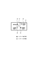
- the details of the automatic operation changeover switch 30 embodied by the operation unit 18 will be described with reference to FIG.
- GUI 2 is assumed to be configured by, for example, a graphical user interface (GUI) displayed on a display and an operation device linked to the GUI.
- GUI operation device include a touch panel for directly touching and operating the GUI display, and a remote operation device for operating the GUI displayed remotely.
- a triangular switch portion 31 is provided in the central portion of the automatic operation changeover switch 30.
- Indicator switches 32, 33, and 34 respectively corresponding to three operation modes of the automatic switching mode, the automatic operation manual on mode, and the automatic operation manual off mode are provided at the triangular apex portions of the switch unit 31.
- These indicator switches 32, 33, and 34 have both a switch for selecting a mode and a function of an indicator for displaying an on / off state of the switch.
- the switch unit 31 is controlled such that when one of the indicator switches is indicated via the operation device, the indicator switch is turned on to switch to the corresponding mode, and the other indicator switches are turned off. .
- the indicator switch 32 is a switch corresponding to the automatic switching mode.
- the automatic switching mode is an operation mode in which the traveling control unit 10 spontaneously switches between the automatic operation mode and the manual operation mode.
- the indicator switch 33 is a switch corresponding to the automatic driving manual on mode.
- the automatic driving manual on mode is an operation mode in which the automatic driving mode is turned on according to a driver's instruction.
- the indicator switch 34 is a switch corresponding to the automatic driving manual off mode.
- the automatic operation manual off mode is an operation mode in which the automatic operation mode is turned off and the manual operation mode is turned on according to a driver's instruction.
- these indicator switches 32, 33, and 34 correspond to the driving assistance status presentation unit of the driving assistance control device.
- a state display area 35 is provided in the upper right part of the automatic operation changeover switch 30. In this state display area 35, information related to the execution state of the automatic operation and an indicator that lights up according to the information content are displayed.
- the state display area 35 corresponds to a driving support status presentation unit of the driving support control device.
- the driver status monitor 19 includes an in-vehicle camera and sensors for observing the driver's state.
- the state of the driver to be observed by the driver status monitor 19 is assumed to be, for example, the movement of the line of sight, the arousal state, the gripping force for gripping the steering wheel, and the like.
- the drive control unit 20 is a control device including an actuator that operates an accelerator or a transmission of the host vehicle.
- the travel control unit 10 controls acceleration / deceleration of the host vehicle by sending a control command to the drive control unit 20 in accordance with a travel plan calculated based on the host vehicle and surrounding conditions.
- the braking control unit 21 is a control device that includes an actuator that operates the brake of the host vehicle.
- the traveling control unit 10 controls the braking of the host vehicle by sending a control command to the braking control unit 21 in accordance with the traveling plan calculated based on the host vehicle and the surrounding situation.
- the steering control unit 22 is a control device including an actuator that operates the steering device of the host vehicle.
- the travel control unit 10 controls the steering of the host vehicle by sending a control command to the steering control unit 22 in accordance with a travel plan calculated based on the host vehicle and surrounding conditions.
- the pedal drive unit 23 is an actuator that operates a brake pedal of the vehicle. In the present embodiment, it is assumed that when the travel control unit 10 switches from the automatic operation mode to the manual operation mode, the driver is alerted by operating the brake via the pedal drive unit 23. Yes.
- the steering wheel drive unit 24 is an actuator that presents haptic information acting on the driver's hand via the steering wheel of the host vehicle.
- the travel control unit 10 switches from the automatic operation mode to the manual operation mode, the driver is alerted by presenting tactile information to the driver via the steering wheel drive unit 24. This is intended for use.
- the seat drive unit 25 is an actuator that presents a tactile force acting on the driver's body through the driver's seat of the vehicle.
- the traveling control unit 10 switches from the automatic operation mode to the manual operation mode, the driver is alerted by presenting tactile information to the driver via the seat driving unit 25. The intended use is assumed.
- the air conditioner control unit 26 is an electronic control device that controls the air conditioning equipment of the host vehicle.
- the air conditioning is appropriately controlled (for example, temperature / air volume change, smell change) via the air conditioner control unit 26. It is assumed that the driver will be alerted to the driver.
- the audio control unit 27 is an electronic control device that controls the acoustic equipment of the host vehicle. In the present embodiment, when the travel control unit 10 switches from the automatic operation mode to the manual operation mode, the audio control unit 27 controls the volume of the audio reproduction sound, the output of the voice message, and the like. It is assumed that the driver will be alerted to the driver.
- reporting part 28 is an output device for alert
- the notification unit 28 is embodied by, for example, a display device that displays an image, an audio output device that outputs audio information, and the like.
- step S100 the traveling control unit 10 starts the switching process with the start of the vehicle.
- step S102 the traveling control unit 10 turns on the manual operation mode and shifts to the operation mode of the driver sovereignty.
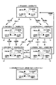
- the automatic driving changeover switch 30 is set to the automatic driving manual off mode as an initial state, and the state display area 35 displays a state in which automatic driving is disabled (see FIG. 4A).
- the traveling control unit 10 acquires various types of information related to the environmental state, the system state, the vehicle state, and the driver state. Specifically, the travel control unit 10 is based on information obtained by the camera 11, the radar 12, the inter-vehicle communication device 13, and the road-to-vehicle communication device 14, other traffic such as surrounding vehicles, signals, signs, roads Information representing surrounding conditions such as shapes and obstacles is acquired as information on the environmental state. Moreover, the traveling control unit 10 acquires information representing a state such as the presence / absence of abnormality in the vehicle system of the recognition / judgment system or the traveling control system, which is input from the vehicle state input unit 16, as information related to the system state.
- the traveling control unit 10 uses information indicating the position and behavior of the host vehicle input from the vehicle state input unit 16 and operation information such as a steering wheel operation, an accelerator operation, and a brake operation by the driver as information on the vehicle state. get. Further, based on the information input from the driver status monitor 19, the traveling control unit 10 acquires information representing the driver's line-of-sight movement, awakening state, gripping force for gripping the steering wheel, and the like as information on the driver state.
- step S106 the traveling control unit 10 determines whether to permit execution of the automatic operation mode using the various information acquired in step S104 as a determination index. Specifically, the travel control unit 10 determines whether or not there is an abnormality that makes it impossible to perform automatic driving, such as an emergency vehicle approach, bad weather, disaster, road abnormality (construction), accident, etc. Understand and determine whether automatic driving is permitted or not. In addition, the traveling control unit 10 grasps the presence / absence of an abnormality that makes automatic driving impossible for the recognition / determination system and the traveling control system vehicle system, and determines whether automatic driving is permitted or not. When it is determined that the automatic operation mode cannot be executed (step S106: NO), the traveling control unit 10 returns to step S104. On the other hand, when it is determined that the execution of the automatic operation mode is permitted (step S106: YES), the traveling control unit 10 proceeds to step S108.
- an abnormality that makes it impossible to perform automatic driving
- the traveling control unit 10 grasps the presence / absence of an abnormality that makes automatic driving impossible for the recognition /
- step S108 the traveling control unit 10 determines whether or not the automatic switching mode is designated in the automatic operation changeover switch 30.
- the traveling control unit 10 proceeds to step S112.
- step S110 the traveling control unit 10 determines whether or not the automatic driving manual on mode is specified in the automatic driving changeover switch 30.
- step S110: NO the traveling control unit 10 returns to step S104.
- step S110: YES the traveling control unit 10 proceeds to step S112.
- step S112 the traveling control unit 10 notifies the driver of information indicating that the manual operation mode is shifted to the automatic operation mode via the notification unit 28.
- the notification of information indicating the transition to the automatic operation mode is performed by display or audio output.
- step S114 the traveling control unit 10 shifts to the automatic operation mode and starts the automatic operation control of the system sovereignty. At this time, based on the operation information input from the vehicle state input unit 16, the traveling control unit 10 determines the conditions (for example, steering wheel operation, accelerator operation, and brake operation) for the driver's operation state to shift to the automatic driving mode. Switch to automatic operation mode completely.
- step S116 the traveling control unit 10 acquires various information related to the environmental state, the system state, the vehicle state, and the driver state. About the acquisition content of information, it is the same as that of the procedure of the above-mentioned step S104.
- step S118 the traveling control unit 10 determines whether or not the automatic switching mode is designated in the automatic operation changeover switch 30. When the automatic switching mode is designated (step S118: YES), the traveling control unit 10 proceeds to step S122. On the other hand, when the automatic switching mode is not designated (step S118: NO), the traveling control unit 10 proceeds to step S120.
- step S120 the traveling control unit 10 determines whether or not the automatic driving manual on mode is designated in the automatic driving changeover switch 30.
- the traveling control unit 10 returns to step S102 and turns on the manual driving mode to operate. It shifts to the operation mode of sovereignty.
- the traveling control unit 10 proceeds to step S122.
- step S122 the traveling control unit 10 determines whether to permit execution of the automatic operation mode using the various information acquired in step S116 as a determination index.
- the specific determination method is the same as the procedure in step S106 described above.
- step S122: YES the traveling control unit 10 returns to step S116.
- step S122: NO the traveling control unit 10 proceeds to step S124.
- step S124 the traveling control unit 10 notifies the driver of information indicating that the automatic operation mode is shifted to the manual operation mode, and executes an awakening operation for the driver as necessary.
- the travel control unit 10 controls the pedal drive unit 23, the steering wheel drive unit 24, the seat drive unit 25, the air conditioner control unit 26, the audio control unit 27, and the notification unit 28 individually or in combination, Raise attention to the driver.
- the traveling control unit 10 grasps the approach of the emergency vehicle, the situation is displayed on the display, or the voice message for alerting is output after the audio reproduction volume is lowered.
- the traveling control unit 10 grasps a state where the driver's awakening level is low (eg, drowsiness, doze), the steering wheel and the seat are shaken to wake the driver. If it still does not wake up, the traveling control unit 10 activates the instantaneous brake once or a plurality of times.
- step S126 the traveling control unit 10 determines whether or not an acceptance condition for shifting to the manual operation mode is established for the driver. Specifically, the traveling control unit 10 satisfies the acceptance condition on the condition that an override operation such as a steering wheel operation, an accelerator operation, a brake operation, or the like by the driver is input to the driving operation based on the automatic driving control. Is determined. Alternatively, the traveling control unit 10 determines that the acceptance condition is satisfied on the condition that an instruction to cancel the automatic operation mode is received from the driver.
- an override operation such as a steering wheel operation, an accelerator operation, a brake operation, or the like by the driver is input to the driving operation based on the automatic driving control. Is determined.
- the traveling control unit 10 determines that the acceptance condition is satisfied on the condition that an instruction to cancel the automatic operation mode is received from the driver.
- step S128 the traveling control unit 10 determines whether a prescribed waiting time for waiting for the acceptance condition to be satisfied has elapsed. When the prescribed waiting time has not elapsed (step S128: NO), the traveling control unit 10 returns to step S124. If it is determined in step S126 that the acceptance condition for shifting to the manual operation mode is satisfied (step S126: YES), the traveling control unit 10 returns to step S102, turns on the manual operation mode, and turns on the driver. Transition to sovereign mode of operation.
- step S128 when it is determined in step S128 that the specified waiting time has elapsed (step S128: YES), the traveling control unit 10 proceeds to step S130.
- step S ⁇ b> 130 the travel control unit 10 performs emergency retreat travel that automatically retreats the host vehicle to a safe place, or vehicle stop that stops the host vehicle.
- the travel control unit 10 sets the automatic driving manual off mode immediately after the vehicle is started, lights up the indicator switch 34, and displays a state in which automatic driving is disabled in the state display area 35.
- the automatic operation changeover switch 30 transitions to the state illustrated in FIG.
- the indicator switch 32 corresponding to the automatic switching mode is lit.
- the state display area 35 displays a state in which automatic driving is not possible.
- the automatic driving changeover switch 30 transitions to the state illustrated in FIG. At this time, the traveling control unit 10 switches from the manual operation mode to the automatic operation mode in accordance with the automatic switching mode.
- the indicator switch 32 corresponding to the automatic switching mode is lit.
- the state display area 35 displays a state during the automatic driving operation.
- the automatic driving changeover switch 30 transitions to the state illustrated in FIG. 4B, and the traveling control unit 10, the automatic operation mode is switched to the manual operation mode.
- the automatic driving changeover switch 30 transitions to the state illustrated in FIG. At this time, the traveling control unit 10 switches from the automatic operation mode to the manual operation mode in accordance with the automatic operation manual off mode. Moreover, in the state illustrated in FIG. 4A, when the travel control unit 10 determines that automatic driving is permitted, the automatic driving changeover switch 30 transitions to the state illustrated in FIG. In the example of FIG. 4D, the indicator switch 34 corresponding to the automatic driving manual off mode is lit. In the state display area 35, the state of automatic operation permission is displayed.
- the automatic operation changeover switch 30 transitions to the state illustrated in FIG. To automatic operation mode.
- the automatic driving changeover switch 30 transitions to the state illustrated in FIG.
- the automatic driving changeover switch 30 transitions to the state illustrated in FIG. At this time, the traveling control unit 10 switches from the manual operation mode to the automatic operation mode in accordance with the automatic operation manual on mode. Moreover, in the state illustrated in FIG. 4C, when the automatic driving manual on mode is designated, the automatic driving changeover switch 30 transitions to the state illustrated in FIG. In the example of FIG. 4E, the indicator switch 33 corresponding to the automatic driving manual on mode is lit. Further, the state display area 35 displays a state during the automatic driving operation.
- the automatic operation changeover switch 30 transitions to the state illustrated in FIG. 4 (c).
- the automatic driving changeover switch 30 transitions to the state illustrated in FIG. To switch from the automatic operation mode to the manual operation mode.
- the driving control unit 10 determines that automatic driving is not possible, the automatic driving changeover switch 30 transitions to the state illustrated in FIG. The control unit 10 switches from the automatic operation mode to the manual operation mode.
- the automatic operation changeover switch 30 is input even when an operation for specifying the automatic operation manual on mode is input when it is determined by the travel control unit 10 that automatic operation is not possible. Switching to automatic operation manual on mode is not performed. That is, the state illustrated in FIG. 4F is not actually established.
- the vehicle travel control system 1 has the following effects.
- An automatic operation manual on / off mode in which switching between the manual operation mode and the automatic operation mode is performed based on the operation of the driver, and an automatic switching mode in which automatic switching is performed are switched via the automatic operation switch 30 by the driver. Can be operated freely.
- the driving control unit 10 determines that the automatic driving cannot be performed
- the automatic driving mode can be set under an inappropriate situation by not accepting the operation specifying the automatic driving manual on mode. It cannot be activated.
- the automatic driving manual on / off mode and the automatic switching mode coexist, it is possible to realize both safety and convenience for the driver.
- the automatic operation changeover switch 30 has a configuration for presenting the selected state of the mode and a state in which the automatic operation is being executed / allowed / impossible to the driver, so that the switching state between the automatic operation mode and the manual operation mode can be indicated.
- the driver can easily grasp it. Thereby, for example, the driver can recognize that the execution of the automatic driving can be performed by the indicator lamp and the voice, and the automatic driving can be executed by operating the switch of the automatic driving manual on mode.
- the traveling control unit 10 determines that an override operation has been detected or an automatic driving mode cancel instruction has been received from the driver.
- the automatic operation mode is switched to the manual operation mode.
- the travel control unit 10 switches from the manual operation mode to the automatic operation mode, the driver accepts the transition to the automatic operation mode by notifying the driver of information indicating the transition to the automatic operation mode in advance. Therefore, it is possible to promptly take an operation state necessary for this purpose.
- the driving control unit 10 switches to the automatic driving mode on condition that the driver's operating condition satisfies the acceptance condition of the automatic driving mode, so that the sovereignty can be safely transferred to the system in a state where the driver is ready to receive. Can be transferred.
- the automatic operation changeover switch 30 may be configured by a combination of a mechanical switch capable of selectively selecting three modes and an indicator capable of presenting a state relating to automatic operation. Good.
- the travel control unit 10 When the travel control unit 10 performs switching from the automatic operation mode to the manual operation mode, the ratio of the driving operation that the automatic driving assumes until the driving operation input by the driver converges to a safe range is gradually increased. You may comprise so that it may reduce. In addition, when the traveling control unit 10 performs switching from the automatic operation mode to the manual operation mode, it may be configured to automatically and slowly decelerate.
- a program is stored in a ROM corresponding to a non-transitional tangible recording medium, and this program is a CPU corresponding to a processor of a computer.
- the program is stored in a non-transitional tangible recording medium other than ROM (for example, non-volatile memory other than ROM), and this program is stored in a CPU or the like.
- the configuration may be executed by the processor.
- a program stored in the non-transitional tangible recording medium is executed by the processor, whereby a method corresponding to this program (for example, a driving support control method). May be configured to be executed.
- each unit of the vehicle travel control system 1 includes software recorded on a non-transitional physical recording medium such as a nonvolatile memory, and the like. You may provide by the computer which performs it, or only software, only hardware, or those combinations.
Abstract
A control unit (10) of the driving assist control device alternatively switches the operation mode between a driving assist mode and a manual driving mode. A user interface unit (18, 30) is configured such that an automatic switching mode, a manual on mode, or a manual off mode can be alternately selected by an input of the driver. A determination unit (10) determines whether the execution of driving assist is approved or disapproved at the present moment on the basis of predetermined indices for determining whether the execution of driving assist is permitted or prohibited. On condition that the automatic switching mode is being specified, the control unit executes the driving assist mode when the execution of driving assist is permitted, or executes the manual driving mode when the execution of driving assist is determined as being prohibited. On condition that the execution of driving assist is being permitted, when a switch for specifying the manual on mode is operated, the control unit executes the driving assist mode. When the execution of driving assist is determined as being prohibited, the user interface unit does not accept the input for specifying the manual on mode.
Description
本出願は、2015年7月21日に出願された日本出願番号2015-144036号に基づくものであって、その優先権の利益を主張するものであり、その特許出願のすべての内容が、参照により本明細書に組み入れられる。
This application is based on Japanese Patent Application No. 2015-1444036 filed on July 21, 2015, and claims the benefit of its priority. Is incorporated herein by reference.
本開示は、車両の走行に係る運転操作を自動的に行う運転支援制御装置に関する。
The present disclosure relates to a driving support control device that automatically performs a driving operation related to traveling of a vehicle.
従来、車両の走行に係る運転操作を運転者に代わって自動的に行う運転支援に関する技術が知られている(例えば、特許文献1参照)。特許文献1には、運転者の操作に基づいて走行を行う手動走行モードと、自動制御による走行を行う自動走行モードとを、運転者による操作に基づいて切換える技術が記載されている。
2. Description of the Related Art Conventionally, a technology related to driving assistance that automatically performs driving operations related to vehicle travel on behalf of a driver is known (see, for example, Patent Document 1). Patent Document 1 describes a technique for switching between a manual travel mode in which travel is performed based on a driver's operation and an automatic travel mode in which travel is performed by automatic control based on an operation by the driver.
特許文献1に記載の先行技術においては、運転者による操作に基づいて手動走行モードと自動走行モードとを切換えるようになっている。これに対し、自車両や周辺環境の状況に応じて、手動走行(又は手動運転ともいう)モードと自動走行(又は運転支援ともいう)モードとをシステムが自発的に切換える技術を導入することが考えられる。
In the prior art described in Patent Document 1, the manual travel mode and the automatic travel mode are switched based on the operation by the driver. On the other hand, it is possible to introduce a technique in which the system spontaneously switches between a manual driving (or manual driving) mode and an automatic driving (or driving support) mode depending on the situation of the host vehicle and the surrounding environment. Conceivable.
手動運転モードと運転支援モードとを自発的に切換え可能にする利点として、運転者の負担を軽減できることが挙げられる。また、運転支援モードの実行中において、運転支援の継続が困難となる状況が生じたことに運転者が気づいていなくても、運転の主権を自発的に運転者に委譲することができることも利点として挙げられる。そこで、手動運転モードと運転支援モードとの切換えを運転者の操作に基づいて行う機能と、自動で切換えを行う機能とを共存させると共に、これらの機能を運転者が自在に扱えるようにするための仕組みが求められる。
An advantage of enabling the manual operation mode and the driving support mode to be switched spontaneously is that the burden on the driver can be reduced. In addition, it is also advantageous to be able to voluntarily delegate driving sovereignty to the driver even when the driver is not aware that a situation that makes it difficult to continue driving support occurs during the execution of the driving support mode. As mentioned. Therefore, the function for switching between the manual operation mode and the driving support mode based on the driver's operation and the function for performing the automatic switching coexist and the driver can handle these functions freely. Is required.
本開示は、手動運転モードと運転支援モードとの切換えを運転者の操作に基づいて行う機能と、自動で切換えを行う機能とを共存させ、かつ、これらの機能を運転者が自在に扱えるようにするための技術を提供することを目的とする。
In the present disclosure, a function for performing switching between the manual operation mode and the driving support mode based on a driver's operation and a function for performing automatic switching coexist, and the driver can freely handle these functions. The purpose is to provide technology for
本開示の一態様によれば、制御部、ユーザインタフェース部、及び判断部を備えた運転支援制御装置が提供される。なお、請求の範囲に記載した括弧内の符号は、一つの態様として後述する実施形態に記載の具体的手段との対応関係を示すものであって、本開示の技術的範囲を限定するものではない。
According to one aspect of the present disclosure, a driving support control device including a control unit, a user interface unit, and a determination unit is provided. In addition, the code | symbol in the parenthesis described in the claim shows the correspondence with the specific means as described in embodiment mentioned later as one aspect, Comprising: It does not limit the technical scope of this indication. Absent.
制御部は、運転支援モードと、手動運転モードとを択一的に切換える。運転支援モードは、自車両の走行に係る運転操作の一部又は全部を自動的に行う運転支援を実行する動作態様である。手動運転モードは、運転支援を行わず運転者の運転操作に基づいて走行を行う動作態様である。
The control unit selectively switches between the driving support mode and the manual driving mode. The driving support mode is an operation mode for executing driving support that automatically performs part or all of the driving operation related to the traveling of the host vehicle. The manual driving mode is an operation mode in which driving is performed based on the driving operation of the driver without driving assistance.
ユーザインタフェース部は、自動切換モードと、手動オンモードと、手動オフモードとを、運転者の入力によって択一的に指定可能に構成される。自動切換モードは、運転支援モードと手動運転モードとの切換えを自発的に行うものである。手動オンモードは、運転者の入力により運転支援モードをオンに指定するものである。手動オフモードは、運転者の入力により運転支援モードをオフに指定するものである。
The user interface unit is configured so that an automatic switching mode, a manual on mode, and a manual off mode can be alternatively specified by a driver input. The automatic switching mode spontaneously switches between the driving support mode and the manual driving mode. In the manual on mode, the driving support mode is designated to be turned on by the driver's input. The manual off mode designates the driving support mode to be turned off by the driver's input.
判断部は、運転支援の実行の可否に関する所定の判断指標に基づいて、現時点での運転支援の実行の許否を判断する。
The determining unit determines whether or not the driving support is currently performed based on a predetermined determination index regarding whether or not the driving support can be performed.
制御部は、ユーザインタフェース部により自動切換モードが指定されている条件下で、判断部により運転支援の実行が許可されている場合、運転支援モードを実行し、判断部により運転支援の実行が不可と判断されている場合、手動運転モードを実行し、判断部により運転支援の実行が許可されている条件下で、ユーザインタフェース部により手動オンモードを指定するスイッチが操作された場合、運転支援モードを実行する。ユーザインタフェース部は、判断部により運転支援の実行が不可と判断されている場合、手動オンモードを指定する入力を受付けない。
The control unit executes the driving support mode under the condition that the automatic switching mode is specified by the user interface unit, and the driving support mode is executed by the determining unit, and the driving support cannot be executed by the determining unit. If the switch that specifies the manual on mode is operated by the user interface unit under the condition that execution of the driving support is permitted by the determination unit, the driving support mode is Execute. The user interface unit does not accept an input for designating the manual on mode when the determination unit determines that execution of driving support is impossible.
本開示の一態様によれば、手動運転モードと運転支援モードとの切換えを運転者の操作に基づいて行う手動オン/オフモードと、自動で切換えを行う自動切換モードとを、ユーザインタフェース部を介して運転者が自在に操作できる。また、運転支援の実行が不可と判断されている状況下では、手動オンモードを受付けないようにすることで、不適切な状況下で運転支援モードが起動されることができないようになっている。これにより、手動オン/オフモードと自動切換モードとが共存するシステムにおいて、安全性と運転者の利便性との両立を実現できる。
According to one aspect of the present disclosure, a manual on / off mode in which switching between the manual driving mode and the driving support mode is performed based on a driver's operation, and an automatic switching mode in which switching is performed automatically are provided. The driver can freely operate via In addition, in a situation where it is determined that driving assistance cannot be performed, the driving assistance mode cannot be activated under inappropriate circumstances by not accepting the manual on mode. . Thereby, in a system in which the manual on / off mode and the automatic switching mode coexist, it is possible to realize both safety and convenience for the driver.
本開示についての上記の目的、その他の目的、特徴、及び利点は、添付の図面を参照しながら下記の詳細な記述により、より明確になる。その図面は、
本開示の一実施形態に係る車両走行制御システムの構成を表すブロック図であり、
図1の操作部を構成する自動運転切換スイッチの構成を表す説明図であり、
図1の走行制御部による切換処理の手順を表すフローチャートであり、
図2の自動運転切換スイッチの状態の変化を表す状態遷移図である。
The above object, other objects, features, and advantages of the present disclosure will become more apparent from the following detailed description with reference to the accompanying drawings. The drawing
It is a block diagram showing a configuration of a vehicle travel control system according to an embodiment of the present disclosure, It is explanatory drawing showing the structure of the automatic driving | operation changeover switch which comprises the operation part of FIG. It is a flowchart showing the procedure of the switching process by the traveling control part of FIG. It is a state transition diagram showing the change of the state of the automatic operation changeover switch of FIG.
以下、本開示の実施形態を図面に基づいて説明する。なお、本開示は、下記の実施形態に限定されるものではなく、様々な態様にて実施することが可能である。
Hereinafter, embodiments of the present disclosure will be described with reference to the drawings. In addition, this indication is not limited to the following embodiment, It is possible to implement in various aspects.
[車両走行制御システムの構成の説明]
本実施形態の車両走行制御システム1の構成について、図1を参照しながら説明する。この車両走行制御システム1は、本開示における運転支援の一例として、自車両の加速・操舵・制動等の運転操作を自動的に行う自動運転を制御するシステムである。 [Description of configuration of vehicle travel control system]
The configuration of the vehicletravel control system 1 of the present embodiment will be described with reference to FIG. The vehicle travel control system 1 is a system that controls automatic driving that automatically performs driving operations such as acceleration, steering, and braking of the host vehicle as an example of driving assistance in the present disclosure.
本実施形態の車両走行制御システム1の構成について、図1を参照しながら説明する。この車両走行制御システム1は、本開示における運転支援の一例として、自車両の加速・操舵・制動等の運転操作を自動的に行う自動運転を制御するシステムである。 [Description of configuration of vehicle travel control system]
The configuration of the vehicle
図1に例示されるとおり、車両走行制御システム1は、走行制御部10と、この走行制御部10に接続される各部によって構成されている。走行制御部10には、カメラ(前方・後方)11、レーダ(前方・後方)12、車車間通信機13、路車間通信機14、位置検出部15、車両状態入力部16、地図データベース17、操作部18、ドライバステータスモニタ19、駆動制御部20、制動制御部21、操舵制御部22、ペダル駆動部23、ステアリングホイール駆動部24、シート駆動部25、エアコン制御部26、オーディオ制御部27、報知部28が接続される。
As illustrated in FIG. 1, the vehicle travel control system 1 includes a travel control unit 10 and each unit connected to the travel control unit 10. The travel control unit 10 includes a camera (front / rear) 11, a radar (front / rear) 12, a vehicle-to-vehicle communication device 13, a road-to-vehicle communication device 14, a position detection unit 15, a vehicle state input unit 16, a map database 17, Operation unit 18, driver status monitor 19, drive control unit 20, braking control unit 21, steering control unit 22, pedal drive unit 23, steering wheel drive unit 24, seat drive unit 25, air conditioner control unit 26, audio control unit 27, The notification unit 28 is connected.
走行制御部10は、CPU(Central Processing Unit)、ROM(Read Only Memory)、RAM(Random Access Memory)、入出力インタフェース等(いずれも不図示)を中心に構成された情報処理装置である。この走行制御部10は、自車両の加速・制動・操舵等の運転操作を自動的に行って自車両を走行させる自動運転機能を制御する。なお、ここでいう自動運転とは、指定された目的地まで自車両を完全に自動で走行させるものを含む。この他にも、例えば、車線逸脱防止支援機能(Lane Keeping Assist System)や、車間・車線制御機能(Adaptive Cruise Control)等のように、自車両の走行に係る運転操作の一部を担う運転支援を受ける走行も含む。なお、走行制御部10は、運転支援制御装置の制御部及び判断部に相当する。
The traveling control unit 10 is an information processing apparatus mainly configured with a CPU (Central Processing Unit), a ROM (Read Only Memory), a RAM (Random Access Memory), an input / output interface and the like (all not shown). The travel control unit 10 controls an automatic driving function that causes the host vehicle to travel by automatically performing driving operations such as acceleration, braking, and steering of the host vehicle. In addition, the automatic driving | operation here includes what makes the own vehicle drive | work fully automatically to the designated destination. In addition to this, for example, driving assistance that bears a part of the driving operation related to the driving of the own vehicle, such as the Lane Keeping Assist System and the Inter-Vehicle and Lane Control Function (Adaptive Cruise Control), etc. Including running. The travel control unit 10 corresponds to a control unit and a determination unit of the driving support control device.
走行制御部10は、自車両の現在地と道路地図データとを比較しながら、目的地までの経路に従って自車両を走行させる。また、走行制御部10は、カメラ11やレーダ12、車車間通信機13、路車間通信機14により周辺車両等の他の交通や、信号、標識、道路形状、障害物といった周辺状況を把握し、安全な走行に必要な加速・制動・操舵の動作を決定する。そして、走行制御部10は、決定した動作に応じて、駆動制御部20や制動制御部21、操舵制御部22等の各種アクチュエータを作動させ、自車両を走行させる。なお、本実施形態では、走行制御部10が実現する機能として、自動運転を行う動作態様である自動運転モードと、自動運転を行わず運転者による運転操作によって走行する動作態様である手動運転モードとの切換を行う制御について説明する。
The traveling control unit 10 causes the host vehicle to travel according to the route to the destination while comparing the current location of the host vehicle with the road map data. In addition, the travel control unit 10 grasps other traffic such as surrounding vehicles and surrounding conditions such as signals, signs, road shapes, and obstacles with the camera 11, the radar 12, the inter-vehicle communication device 13, and the road-to-vehicle communication device 14. Determine the acceleration, braking and steering operations required for safe driving. Then, the travel control unit 10 operates various actuators such as the drive control unit 20, the braking control unit 21, and the steering control unit 22 according to the determined operation, and causes the vehicle to travel. In the present embodiment, the functions realized by the traveling control unit 10 include an automatic operation mode that is an operation mode in which automatic driving is performed and a manual operation mode that is an operation mode in which driving is performed by a driver without performing automatic driving. Control for switching between and will be described.
カメラ11は、車両の前方及び後方それぞれに設置された撮像装置であり、自車両の前方領域及び後方領域を撮像し、撮像された画像のデータを走行制御部10に出力する。レーダ12は、自車両の前方及び後方それぞれの検出対象範囲に向けて電波やレーザ光を発信し、その反射波を受信することにより対象物の有無や対象物までの距離を検出するセンサである。本実施形態では、カメラ11及びレーダ12を自車両の前方及び後方に存在する他車両や障害物、道路形状等を認識するための光学的あるいは電磁的なセンサとして用いることを想定している。
The camera 11 is an imaging device installed at each of the front and rear of the vehicle, images the front area and the rear area of the host vehicle, and outputs data of the captured image to the travel control unit 10. The radar 12 is a sensor that detects the presence / absence of a target object and the distance to the target object by transmitting radio waves and laser light toward the detection target ranges in front and rear of the host vehicle and receiving the reflected waves. . In the present embodiment, it is assumed that the camera 11 and the radar 12 are used as optical or electromagnetic sensors for recognizing other vehicles, obstacles, road shapes, and the like existing in front and rear of the host vehicle.
車車間通信機13は、他の車両に搭載された車載通信装置との間で無線通信(車車間通信)を行う無線通信装置である。走行制御部10は、車車間通信機13の無線通信可能圏内に存在する周辺車両と車車間通信を行い、当該周辺車両に関する各種情報を取得する。本実施形態では、車車間通信機13により他車両から取得した情報に基づき、周辺車両の位置や速度、加速度、進行方向等の挙動を把握する用途を想定している。
The inter-vehicle communication device 13 is a wireless communication device that performs wireless communication (vehicle-to-vehicle communication) with an in-vehicle communication device mounted on another vehicle. The traveling control unit 10 performs vehicle-to-vehicle communication with a surrounding vehicle that exists within a wireless communicable range of the vehicle-to-vehicle communication device 13 and acquires various information related to the surrounding vehicle. In the present embodiment, an application is assumed in which behaviors such as the position, speed, acceleration, and traveling direction of surrounding vehicles are grasped based on information acquired from other vehicles by the inter-vehicle communication device 13.
路車間通信機14は、路上に設置された車両状況検出装置(路側装置)から提供される車両検出情報を受信するための無線通信装置である。本実施形態では、路側装置によって周辺の監視対象範囲に存在する各車両の位置や速度、加速度、進行方向等の挙動が検出され、各車両に関する車両検出情報が無線通信によりに提供される用途を想定している。走行制御部10は、路車間通信機14により路側装置から受信した車両検出情報に基づき、周辺を走行する各車両の位置や挙動を把握する。
The road-to-vehicle communication device 14 is a wireless communication device for receiving vehicle detection information provided from a vehicle state detection device (roadside device) installed on the road. In this embodiment, the roadside device detects the behavior of each vehicle existing in the surrounding monitoring target range, such as position, speed, acceleration, traveling direction, etc., and uses vehicle detection information related to each vehicle by wireless communication. Assumed. The traveling control unit 10 grasps the position and behavior of each vehicle traveling around the vehicle based on the vehicle detection information received from the roadside device by the road-to-vehicle communication device 14.
位置検出部15は、GPS(Global Positioning System)受信機や、ジャイロセンサ、車速センサ(いずれも不図示)等による検出結果に基づいて自車両の現在地を検出し、検出した現在地情報を走行制御部10に出力する。
The position detection unit 15 detects the current location of the host vehicle based on detection results from a GPS (Global Positioning System) receiver, a gyro sensor, a vehicle speed sensor (all not shown), and the travel control unit 10 is output.
車両状態入力部16は、車両状態を表す各種情報を走行制御部10に入力する。本実施形態では、車両状態を表す情報として、速度や加速度、角速度等の自車両の挙動を計測するセンサによる計測値や、車両システム(認知・判断系、走行制御系)の状態、運転者によるハンドル操作、アクセル操作、ブレーキ操作等の操作信号等を想定している。なお、車両状態入力部16は、運転支援制御装置の動作検出部に相当する。
The vehicle state input unit 16 inputs various information representing the vehicle state to the travel control unit 10. In the present embodiment, as information representing the vehicle state, measured values by sensors that measure the behavior of the host vehicle such as speed, acceleration, and angular velocity, the state of the vehicle system (cognition / judgment system, travel control system), and the driver Operation signals such as steering wheel operation, accelerator operation, and brake operation are assumed. The vehicle state input unit 16 corresponds to an operation detection unit of the driving support control device.
地図データベース17は、経路案内用の地図データを記憶する記憶装置である。この地図データには、道路の結節点に対応するノードデータ、ノード間の道路区間に対応するリンクデータ、ノード及びリンクに対応する属性データ、施設データ等の各種データが含まれる。
The map database 17 is a storage device that stores map data for route guidance. The map data includes various data such as node data corresponding to road nodal points, link data corresponding to road sections between nodes, attribute data corresponding to nodes and links, and facility data.
操作部18は、車両走行制御システム1に対する運転者からの操作指示を入力するためのユーザインタフェースである。この操作部18は、自動運転モードと手動運転モードとの切換方法を指定するための自動運転切換スイッチ30の機能を提供する。この操作部18は、自動運転切換スイッチ30と共に、運転支援制御装置のユーザインタフェース部に相当する。以下、操作部18によって具現化される自動運転切換スイッチ30の詳細について、図2を参照しながら説明する。
The operation unit 18 is a user interface for inputting an operation instruction from the driver to the vehicle travel control system 1. The operation unit 18 provides a function of the automatic operation changeover switch 30 for designating a switching method between the automatic operation mode and the manual operation mode. The operation unit 18 corresponds to the user interface unit of the driving support control device together with the automatic driving changeover switch 30. Hereinafter, the details of the automatic operation changeover switch 30 embodied by the operation unit 18 will be described with reference to FIG.
図2に例示される自動運転切換スイッチ30は、例えば、ディスプレイに表示されたグラフィカルユーザインタフェース(GUI)と、このGUIと連動する操作デバイスによって構成されたものを想定している。GUIの操作デバイスとしては、GUIの表示に直接触れて操作するためのタッチパネルや、遠隔に表示されたGUIを手元で操作するための遠隔操作デバイス等が例示される。
2 is assumed to be configured by, for example, a graphical user interface (GUI) displayed on a display and an operation device linked to the GUI. Examples of the GUI operation device include a touch panel for directly touching and operating the GUI display, and a remote operation device for operating the GUI displayed remotely.
図2に例示されるとおり、自動運転切換スイッチ30の中央部分には、三角形状のスイッチ部31が設けられている。このスイッチ部31における三角形状の各頂点部分には、自動切換モード、自動運転手動オンモード及び自動運転手動オフモードの3つの動作態様にそれぞれ対応するインジケータスイッチ32、33、34が設けられている。これらのインジケータスイッチ32、33、34は、モードを選択するスイッチと、スイッチのオン/オフ状態を表示するインジケータの機能とを併せ持つ。スイッチ部31は、操作デバイスを介していずれかのインジケータスイッチが指し示されることで、そのインジケータスイッチが点灯して対応するモードに切換わると共に、他のインジケータスイッチがオフになるように制御される。
As illustrated in FIG. 2, a triangular switch portion 31 is provided in the central portion of the automatic operation changeover switch 30. Indicator switches 32, 33, and 34 respectively corresponding to three operation modes of the automatic switching mode, the automatic operation manual on mode, and the automatic operation manual off mode are provided at the triangular apex portions of the switch unit 31. . These indicator switches 32, 33, and 34 have both a switch for selecting a mode and a function of an indicator for displaying an on / off state of the switch. The switch unit 31 is controlled such that when one of the indicator switches is indicated via the operation device, the indicator switch is turned on to switch to the corresponding mode, and the other indicator switches are turned off. .
インジケータスイッチ32は、自動切換モードに対応するスイッチである。自動切換モードは、自動運転モードと手動運転モードとの切換えを走行制御部10が自発的に行う動作態様である。インジケータスイッチ33は、自動運転手動オンモードに対応するスイッチである。自動運転手動オンモードは、運転者の指示により自動運転モードをオンにする動作態様である。インジケータスイッチ34は、自動運転手動オフモードに対応するスイッチである。自動運転手動オフモードは、運転者の指示により自動運転モードをオフにして手動運転モードをオンする動作態様である。なお、これらのインジケータスイッチ32、33、34は、運転支援制御装置の運転支援状況提示部に相当する。
The indicator switch 32 is a switch corresponding to the automatic switching mode. The automatic switching mode is an operation mode in which the traveling control unit 10 spontaneously switches between the automatic operation mode and the manual operation mode. The indicator switch 33 is a switch corresponding to the automatic driving manual on mode. The automatic driving manual on mode is an operation mode in which the automatic driving mode is turned on according to a driver's instruction. The indicator switch 34 is a switch corresponding to the automatic driving manual off mode. The automatic operation manual off mode is an operation mode in which the automatic operation mode is turned off and the manual operation mode is turned on according to a driver's instruction. In addition, these indicator switches 32, 33, and 34 correspond to the driving assistance status presentation unit of the driving assistance control device.
また、自動運転切換スイッチ30の右上部分には、状態表示領域35が設けられている。この状態表示領域35には、自動運転の実行状態に関する情報と、情報内容に応じて点灯するインジケータとが表示される。この状態表示領域35は、運転支援制御装置の運転支援状況提示部に相当する。
Further, a state display area 35 is provided in the upper right part of the automatic operation changeover switch 30. In this state display area 35, information related to the execution state of the automatic operation and an indicator that lights up according to the information content are displayed. The state display area 35 corresponds to a driving support status presentation unit of the driving support control device.
図1のブロック図の説明に戻る。ドライバステータスモニタ19は、運転者の状態を観測するための車内カメラやセンサ類により構成される。本実施形態では、ドライバステータスモニタ19による観測の対象となる運転者の状態として、例えば、視線の動きや覚醒状態、ステアリングホイールを握る握力等を想定している。
Returning to the block diagram of FIG. The driver status monitor 19 includes an in-vehicle camera and sensors for observing the driver's state. In the present embodiment, the state of the driver to be observed by the driver status monitor 19 is assumed to be, for example, the movement of the line of sight, the arousal state, the gripping force for gripping the steering wheel, and the like.
駆動制御部20は、自車両のアクセルや変速機を作動させるアクチュエータを備える制御装置である。走行制御部10は、自車両及び周辺の状況に基づいて演算された走行計画に従って駆動制御部20に制御指令を送出することにより、自車両の加減速を制御する。
The drive control unit 20 is a control device including an actuator that operates an accelerator or a transmission of the host vehicle. The travel control unit 10 controls acceleration / deceleration of the host vehicle by sending a control command to the drive control unit 20 in accordance with a travel plan calculated based on the host vehicle and surrounding conditions.
制動制御部21は、自車両のブレーキを作動させるアクチュエータを備える制御装置である。走行制御部10は、自車両及び周辺の状況に基づいて演算された走行計画に従って制動制御部21に制御指令を送出することにより、自車両の制動を制御する。
The braking control unit 21 is a control device that includes an actuator that operates the brake of the host vehicle. The traveling control unit 10 controls the braking of the host vehicle by sending a control command to the braking control unit 21 in accordance with the traveling plan calculated based on the host vehicle and the surrounding situation.
操舵制御部22は、自車両の操舵装置を作動させるアクチュエータを備える制御装置である。走行制御部10は、自車両及び周辺の状況に基づいて演算された走行計画に従って操舵制御部22に制御指令を送出することにより、自車両の操舵を制御する。
The steering control unit 22 is a control device including an actuator that operates the steering device of the host vehicle. The travel control unit 10 controls the steering of the host vehicle by sending a control command to the steering control unit 22 in accordance with a travel plan calculated based on the host vehicle and surrounding conditions.
ペダル駆動部23は、車両のブレーキペダルを作動させるアクチュエータである。本実施形態では、走行制御部10が自動運転モードから手動運転モードへの切換えを行う際に、ペダル駆動部23を介してブレーキを作動させることで運転者に対する注意喚起を行う用途を想定している。
The pedal drive unit 23 is an actuator that operates a brake pedal of the vehicle. In the present embodiment, it is assumed that when the travel control unit 10 switches from the automatic operation mode to the manual operation mode, the driver is alerted by operating the brake via the pedal drive unit 23. Yes.
ステアリングホイール駆動部24は、自車両のステアリングホイールを介して運転者の手に作用する触力覚的情報を提示するアクチュエータである。本実施形態では、走行制御部10が自動運転モードから手動運転モードへの切換えを行う際に、ステアリングホイール駆動部24を介して運転者に対して触力覚的情報を提示することで注意喚起を行う用途を想定している。
The steering wheel drive unit 24 is an actuator that presents haptic information acting on the driver's hand via the steering wheel of the host vehicle. In the present embodiment, when the travel control unit 10 switches from the automatic operation mode to the manual operation mode, the driver is alerted by presenting tactile information to the driver via the steering wheel drive unit 24. This is intended for use.
シート駆動部25は、自車両の運転座席を介して運転者の身体に作用する触力覚的を提示するアクチュエータである。本実施形態では、走行制御部10が自動運転モードから手動運転モードへの切換えを行う際に、シート駆動部25を介して運転者に対して触力覚的情報を提示することで注意喚起を行う用途を想定している。
The seat drive unit 25 is an actuator that presents a tactile force acting on the driver's body through the driver's seat of the vehicle. In the present embodiment, when the traveling control unit 10 switches from the automatic operation mode to the manual operation mode, the driver is alerted by presenting tactile information to the driver via the seat driving unit 25. The intended use is assumed.
エアコン制御部26は、自車両の空調機器を制御する電子制御装置である。本実施形態では、走行制御部10が自動運転モードから手動運転モードへの切換えを行う際に、エアコン制御部26を介して空調を適度に制御(例えば、温度・風量変化、におい変化)することで運転者に対して注意喚起を行う用途を想定している。
The air conditioner control unit 26 is an electronic control device that controls the air conditioning equipment of the host vehicle. In the present embodiment, when the travel control unit 10 switches from the automatic operation mode to the manual operation mode, the air conditioning is appropriately controlled (for example, temperature / air volume change, smell change) via the air conditioner control unit 26. It is assumed that the driver will be alerted to the driver.
オーディオ制御部27は、自車両の音響機器を制御する電子制御装置である。本実施形態では、走行制御部10が自動運転モードから手動運転モードへの切換えを行う際に、オーディオ制御部27を介してオーディオの再生音の音量調整や音声メッセージの出力等の制御を行うことで運転者に対して注意喚起を行う用途を想定している。
The audio control unit 27 is an electronic control device that controls the acoustic equipment of the host vehicle. In the present embodiment, when the travel control unit 10 switches from the automatic operation mode to the manual operation mode, the audio control unit 27 controls the volume of the audio reproduction sound, the output of the voice message, and the like. It is assumed that the driver will be alerted to the driver.
報知部28は、運転者に対して各種情報を報知するための出力装置である。この報知部28は、例えば、画像を表示する表示装置や、音声情報を出力する音声出力装置等で具現化される。
The alerting | reporting part 28 is an output device for alert | reporting various information with respect to a driver | operator. The notification unit 28 is embodied by, for example, a display device that displays an image, an audio output device that outputs audio information, and the like.
[切換処理の説明]
走行制御部10が実行する切換処理の手順について、図3のフローチャートを参照しながら説明する。 [Description of switching process]
The procedure of the switching process performed by thetravel control unit 10 will be described with reference to the flowchart of FIG.
走行制御部10が実行する切換処理の手順について、図3のフローチャートを参照しながら説明する。 [Description of switching process]
The procedure of the switching process performed by the
ステップS100では、車両の起動に伴い走行制御部10が切換処理を開始する。ステップS102では、走行制御部10は、手動運転モードをオンにして運転者主権の動作態様に移行する。なお、車両の起動直後においては、自動運転切換スイッチ30の初期状態として自動運転手動オフモードにセットすると共に、状態表示領域35において自動運転不可の状態を表示する(図4(a)参照)。
In step S100, the traveling control unit 10 starts the switching process with the start of the vehicle. In step S102, the traveling control unit 10 turns on the manual operation mode and shifts to the operation mode of the driver sovereignty. Immediately after the vehicle is started, the automatic driving changeover switch 30 is set to the automatic driving manual off mode as an initial state, and the state display area 35 displays a state in which automatic driving is disabled (see FIG. 4A).
図3のフローチャートの説明に戻る。ステップS104では、走行制御部10は、環境状態、システム状態、車両状態、及びドライバ状態に関する各種情報を取得する。具体的には、走行制御部10は、カメラ11、レーダ12、車車間通信機13、路車間通信機14によって得られた情報に基づき、周辺車両等の他の交通や、信号、標識、道路形状、障害物といった周辺状況を表す情報を、環境状態に関する情報として取得する。また、走行制御部10は、車両状態入力部16から入力される認知・判断系や走行制御系の車両システムにおける異常の有無等の状態を表す情報を、システム状態に関する情報として取得する。
Returning to the flowchart of FIG. In step S104, the traveling control unit 10 acquires various types of information related to the environmental state, the system state, the vehicle state, and the driver state. Specifically, the travel control unit 10 is based on information obtained by the camera 11, the radar 12, the inter-vehicle communication device 13, and the road-to-vehicle communication device 14, other traffic such as surrounding vehicles, signals, signs, roads Information representing surrounding conditions such as shapes and obstacles is acquired as information on the environmental state. Moreover, the traveling control unit 10 acquires information representing a state such as the presence / absence of abnormality in the vehicle system of the recognition / judgment system or the traveling control system, which is input from the vehicle state input unit 16, as information related to the system state.
また、走行制御部10は、車両状態入力部16から入力される自車両の位置や挙動を表す情報や、運転者によるハンドル操作、アクセル操作、ブレーキ操作等の操作情報を、車両状態に関する情報として取得する。また、走行制御部10は、ドライバステータスモニタ19から入力される情報に基づき、運転者の視線の動きや覚醒状態、ステアリングホイールを握る握力等を表す情報をドライバ状態に関する情報として取得する。
In addition, the traveling control unit 10 uses information indicating the position and behavior of the host vehicle input from the vehicle state input unit 16 and operation information such as a steering wheel operation, an accelerator operation, and a brake operation by the driver as information on the vehicle state. get. Further, based on the information input from the driver status monitor 19, the traveling control unit 10 acquires information representing the driver's line-of-sight movement, awakening state, gripping force for gripping the steering wheel, and the like as information on the driver state.
ステップS106では、走行制御部10は、ステップS104で取得した各種情報を判断指標として用いて、自動運転モードの実行を許可するか否かを判定する。具体的には、走行制御部10は、自車両周辺の走行環境について、例えば、緊急車両の接近、悪天候、災害、道路異常(工事)、事故等の自動運転が不可能となる異常の有無を把握し、自動運転の許否を判断する。また、走行制御部10は、認知・判断系や走行制御系の車両システムについて、自動運転が不可能となる異常の有無を把握し、自動運転の許否を判断する。自動運転モードの実行が不可と判断された場合(ステップS106:NO)、走行制御部10は、ステップS104に戻る。一方、自動運転モードの実行が許可と判断された場合(ステップS106:YES)、走行制御部10は、ステップS108に進む。
In step S106, the traveling control unit 10 determines whether to permit execution of the automatic operation mode using the various information acquired in step S104 as a determination index. Specifically, the travel control unit 10 determines whether or not there is an abnormality that makes it impossible to perform automatic driving, such as an emergency vehicle approach, bad weather, disaster, road abnormality (construction), accident, etc. Understand and determine whether automatic driving is permitted or not. In addition, the traveling control unit 10 grasps the presence / absence of an abnormality that makes automatic driving impossible for the recognition / determination system and the traveling control system vehicle system, and determines whether automatic driving is permitted or not. When it is determined that the automatic operation mode cannot be executed (step S106: NO), the traveling control unit 10 returns to step S104. On the other hand, when it is determined that the execution of the automatic operation mode is permitted (step S106: YES), the traveling control unit 10 proceeds to step S108.
ステップS108では、走行制御部10は、自動運転切換スイッチ30において自動切換モードが指定されているか否かを判定する。自動切換モードが指定されている場合(ステップS108:YES)、走行制御部10は、ステップS112に進む。一方、自動切換モードが指定されていない場合(ステップS108:NO)、走行制御部10は、ステップS110に進む。ステップS110では、走行制御部10は、自動運転切換スイッチ30において自動運転手動オンモードが指定されているか否かを判定する。自動運転手動オンモードが指定されていない場合、すなわち自動運転手動オフモードが指定されている場合(ステップS110:NO)、走行制御部10は、ステップS104に戻る。一方、自動運転手動オンモードが指定されている場合(ステップS110:YES)、走行制御部10は、ステップS112に進む。
In step S108, the traveling control unit 10 determines whether or not the automatic switching mode is designated in the automatic operation changeover switch 30. When the automatic switching mode is designated (step S108: YES), the traveling control unit 10 proceeds to step S112. On the other hand, when the automatic switching mode is not designated (step S108: NO), the traveling control unit 10 proceeds to step S110. In step S110, the traveling control unit 10 determines whether or not the automatic driving manual on mode is specified in the automatic driving changeover switch 30. When the automatic driving manual on mode is not designated, that is, when the automatic driving manual off mode is designated (step S110: NO), the traveling control unit 10 returns to step S104. On the other hand, when the automatic driving manual on mode is designated (step S110: YES), the traveling control unit 10 proceeds to step S112.
ステップS112では、走行制御部10は、手動運転モードから自動運転モードに移行することを示す情報を、報知部28を介して運転者に対して報知する。自動運転モードに移行することを示す情報の報知は、表示又は音声出力によって行う。ステップS114では、走行制御部10は、自動運転モードに移行してシステム主権の自動運転制御を開始する。このとき、走行制御部10は、車両状態入力部16から入力される操作情報に基づいて、運転者の動作状態が自動運転モードに移行するための条件(例えば、ハンドル操作、アクセル操作及びブレーキ操作がいずれも無入力)を満たす場合、完全に自動運転モードに切換える。
In step S112, the traveling control unit 10 notifies the driver of information indicating that the manual operation mode is shifted to the automatic operation mode via the notification unit 28. The notification of information indicating the transition to the automatic operation mode is performed by display or audio output. In step S114, the traveling control unit 10 shifts to the automatic operation mode and starts the automatic operation control of the system sovereignty. At this time, based on the operation information input from the vehicle state input unit 16, the traveling control unit 10 determines the conditions (for example, steering wheel operation, accelerator operation, and brake operation) for the driver's operation state to shift to the automatic driving mode. Switch to automatic operation mode completely.
ステップS116では、走行制御部10は、環境状態、システム状態、車両状態、及びドライバ状態に関する各種情報を取得する。情報の取得内容については、上述のステップS104の手順と同様である。ステップS118では、走行制御部10は、自動運転切換スイッチ30において自動切換モードが指定されているか否かを判定する。自動切換モードが指定されている場合(ステップS118:YES)、走行制御部10は、ステップS122に進む。一方、自動切換モードが指定されていない場合(ステップS118:NO)、走行制御部10は、ステップS120に進む。
In step S116, the traveling control unit 10 acquires various information related to the environmental state, the system state, the vehicle state, and the driver state. About the acquisition content of information, it is the same as that of the procedure of the above-mentioned step S104. In step S118, the traveling control unit 10 determines whether or not the automatic switching mode is designated in the automatic operation changeover switch 30. When the automatic switching mode is designated (step S118: YES), the traveling control unit 10 proceeds to step S122. On the other hand, when the automatic switching mode is not designated (step S118: NO), the traveling control unit 10 proceeds to step S120.
ステップS120では、走行制御部10は、自動運転切換スイッチ30において自動運転手動オンモードが指定されているか否かを判定する。自動運転手動オンモードが指定されていない場合、すなわち自動運転手動オフモードが指定されている場合(ステップS120:NO)、走行制御部10は、ステップS102に戻り、手動運転モードをオンにして運転者主権の動作態様に移行する。一方、自動運転手動オンモードが指定されている場合(ステップS120:YES)、走行制御部10は、ステップS122に進む。
In step S120, the traveling control unit 10 determines whether or not the automatic driving manual on mode is designated in the automatic driving changeover switch 30. When the automatic driving manual on mode is not designated, that is, when the automatic driving manual off mode is designated (step S120: NO), the traveling control unit 10 returns to step S102 and turns on the manual driving mode to operate. It shifts to the operation mode of sovereignty. On the other hand, when the automatic driving manual on mode is designated (step S120: YES), the traveling control unit 10 proceeds to step S122.
ステップS122では、走行制御部10は、ステップS116で取得した各種情報を判断指標として用いて、自動運転モードの実行を許可するか否かを判定する。具体的な判断方法については、上述のステップS106の手順と同様である。自動運転モードの実行が許可と判断された場合(ステップS122:YES)、走行制御部10は、ステップS116に戻る。一方、自動運転モードの実行が不可と判断された場合(ステップS122:NO)、走行制御部10は、ステップS124に進む。
In step S122, the traveling control unit 10 determines whether to permit execution of the automatic operation mode using the various information acquired in step S116 as a determination index. The specific determination method is the same as the procedure in step S106 described above. When it is determined that execution of the automatic operation mode is permitted (step S122: YES), the traveling control unit 10 returns to step S116. On the other hand, when it is determined that the automatic operation mode cannot be executed (step S122: NO), the traveling control unit 10 proceeds to step S124.
ステップS124では、走行制御部10は、自動運転モードから手動運転モードに移行することを示す情報を運転者に対して報知すると共に、必要に応じて運転者に対する覚醒動作を実行する。具体的には、走行制御部10は、ペダル駆動部23、ステアリングホイール駆動部24、シート駆動部25、エアコン制御部26、オーディオ制御部27、報知部28を単独又は複数併せて制御して、運転者に対する注意喚起を行う。例えば、走行制御部10が緊急車両の接近を把握した場合、その状況をディスプレイに表示したり、オーディオの再生音量を下げた上で注意喚起のための音声メッセージを出力したりする。また、走行制御部10が運転者の覚醒度が低下(例えば、眠気、居眠り)している状態を把握した場合、ステアリングホイールやシートを震動させて運転者を覚醒させる。それでも覚醒しない場合、走行制御部10は、瞬時のブレーキを一度又は複数回作動させる。
In step S124, the traveling control unit 10 notifies the driver of information indicating that the automatic operation mode is shifted to the manual operation mode, and executes an awakening operation for the driver as necessary. Specifically, the travel control unit 10 controls the pedal drive unit 23, the steering wheel drive unit 24, the seat drive unit 25, the air conditioner control unit 26, the audio control unit 27, and the notification unit 28 individually or in combination, Raise attention to the driver. For example, when the traveling control unit 10 grasps the approach of the emergency vehicle, the situation is displayed on the display, or the voice message for alerting is output after the audio reproduction volume is lowered. Further, when the traveling control unit 10 grasps a state where the driver's awakening level is low (eg, drowsiness, doze), the steering wheel and the seat are shaken to wake the driver. If it still does not wake up, the traveling control unit 10 activates the instantaneous brake once or a plurality of times.
ステップS126では、走行制御部10は、運転者について手動運転モードに移行するための受入条件が成立したか否かを判定する。具体的には、走行制御部10は、自動運転制御に基づく運転操作に対して運転者によるハンドル操作、アクセル操作、ブレーキ操作等のオーバーライド操作が入力されたことを条件に、受入条件が成立したと判定する。あるいは、走行制御部10は、運転者から自動運転モードの解除指示を受付けたことを条件に、受入条件が成立したと判定する。
In step S126, the traveling control unit 10 determines whether or not an acceptance condition for shifting to the manual operation mode is established for the driver. Specifically, the traveling control unit 10 satisfies the acceptance condition on the condition that an override operation such as a steering wheel operation, an accelerator operation, a brake operation, or the like by the driver is input to the driving operation based on the automatic driving control. Is determined. Alternatively, the traveling control unit 10 determines that the acceptance condition is satisfied on the condition that an instruction to cancel the automatic operation mode is received from the driver.
手動運転モードに移行するための受入条件が成立していない場合(S126:NO)、走行制御部10は、ステップS128に進む。ステップS128では、走行制御部10は、受入条件の成立を待つための規定の待ち時間が経過したか否かを判定する。規定の待ち時間が経過していない場合(ステップS128:NO)、走行制御部10は、ステップS124に戻る。そして、ステップS126において手動運転モードに移行するための受入条件が成立したと判定された場合(ステップS126:YES)、走行制御部10は、ステップS102に戻り、手動運転モードをオンにして運転者主権の動作態様に移行する。
If the acceptance condition for shifting to the manual operation mode is not satisfied (S126: NO), the traveling control unit 10 proceeds to step S128. In step S128, the traveling control unit 10 determines whether a prescribed waiting time for waiting for the acceptance condition to be satisfied has elapsed. When the prescribed waiting time has not elapsed (step S128: NO), the traveling control unit 10 returns to step S124. If it is determined in step S126 that the acceptance condition for shifting to the manual operation mode is satisfied (step S126: YES), the traveling control unit 10 returns to step S102, turns on the manual operation mode, and turns on the driver. Transition to sovereign mode of operation.
一方、ステップS128において、規定の待ち時間が経過したと判定された場合(ステップS128:YES)、走行制御部10は、ステップS130に進む。ステップS130では、走行制御部10は、自車両を安全な場所に自動的に退避させる緊急退避走行、又は自車両を停止させる車両停止を実施する。
On the other hand, when it is determined in step S128 that the specified waiting time has elapsed (step S128: YES), the traveling control unit 10 proceeds to step S130. In step S <b> 130, the travel control unit 10 performs emergency retreat travel that automatically retreats the host vehicle to a safe place, or vehicle stop that stops the host vehicle.
[自動運転切換スイッチの状態変化に関する説明]
図4を参照しながら、各モードの指定状況や自動運転の実行状況に応じたシーン別の自動運転切換スイッチ30の状態変化について説明する。 [Explanation regarding state change of automatic operation changeover switch]
With reference to FIG. 4, the state change of the automaticoperation changeover switch 30 for each scene according to the designation status of each mode and the execution status of automatic operation will be described.
図4を参照しながら、各モードの指定状況や自動運転の実行状況に応じたシーン別の自動運転切換スイッチ30の状態変化について説明する。 [Explanation regarding state change of automatic operation changeover switch]
With reference to FIG. 4, the state change of the automatic
図4(a)の事例は、車両の起動直後における自動運転切換スイッチ30の初期状態に相当する。走行制御部10は、車両起動直後に自動運転手動オフモードにセットしてインジケータスイッチ34を点灯させると共に、状態表示領域35において自動運転不可の状態を表示させる。
4A corresponds to the initial state of the automatic operation changeover switch 30 immediately after the vehicle is started. The travel control unit 10 sets the automatic driving manual off mode immediately after the vehicle is started, lights up the indicator switch 34, and displays a state in which automatic driving is disabled in the state display area 35.
図4(a)に例示される状態において自動切換モードが指定されることで、自動運転切換スイッチ30は図4(b)に例示される状態に遷移する。図4(b)の事例では、自動切換モードに対応するインジケータスイッチ32が点灯している。また、状態表示領域35には自動運転不可の状態が表示されている。図4(b)に例示される状態において自動運転手動オフモードが指定された場合、自動運転切換スイッチ30は、図4(a)に例示される状態に遷移する。
When the automatic switching mode is designated in the state illustrated in FIG. 4A, the automatic operation changeover switch 30 transitions to the state illustrated in FIG. In the case of FIG. 4B, the indicator switch 32 corresponding to the automatic switching mode is lit. Further, the state display area 35 displays a state in which automatic driving is not possible. When the automatic driving manual off mode is designated in the state illustrated in FIG. 4B, the automatic driving changeover switch 30 transitions to the state illustrated in FIG.
一方、図4(b)に例示される状態において、走行制御部10によって自動運転許可と判定された場合、自動運転切換スイッチ30は、図4(c)に例示される状態に遷移する。このとき、走行制御部10は、自動切換モードに則って手動運転モードから自動運転モードに切換える。図4(c)の事例では、自動切換モードに対応するインジケータスイッチ32が点灯している。また、状態表示領域35には、自動運転作動中の状態が表示されている。図4(c)に例示される状態において、走行制御部10によって自動運転不可と判定された場合、自動運転切換スイッチ30は、図4(b)に例示される状態に遷移し、走行制御部10により自動運転モードから手動運転モードに切換えられる。
On the other hand, in the state illustrated in FIG. 4B, when the driving control unit 10 determines that automatic driving is permitted, the automatic driving changeover switch 30 transitions to the state illustrated in FIG. At this time, the traveling control unit 10 switches from the manual operation mode to the automatic operation mode in accordance with the automatic switching mode. In the case of FIG. 4C, the indicator switch 32 corresponding to the automatic switching mode is lit. Further, the state display area 35 displays a state during the automatic driving operation. In the state illustrated in FIG. 4C, when it is determined by the traveling control unit 10 that automatic driving is not possible, the automatic driving changeover switch 30 transitions to the state illustrated in FIG. 4B, and the traveling control unit 10, the automatic operation mode is switched to the manual operation mode.
一方、図4(c)に例示される状態において、自動運転手動オフモードが指定された場合、自動運転切換スイッチ30は、図4(d)に例示される状態に遷移する。このとき、走行制御部10は、自動運転手動オフモードに則って自動運転モードから手動運転モードに切換える。また、図4(a)に例示される状態において、走行制御部10により自動運転許可と判定された場合、自動運転切換スイッチ30は、図4(d)に例示される状態に遷移する。図4(d)の事例では、自動運転手動オフモードに対応するインジケータスイッチ34が点灯している。また、状態表示領域35には、自動運転許可の状態が表示されている。
On the other hand, when the automatic driving manual off mode is designated in the state illustrated in FIG. 4C, the automatic driving changeover switch 30 transitions to the state illustrated in FIG. At this time, the traveling control unit 10 switches from the automatic operation mode to the manual operation mode in accordance with the automatic operation manual off mode. Moreover, in the state illustrated in FIG. 4A, when the travel control unit 10 determines that automatic driving is permitted, the automatic driving changeover switch 30 transitions to the state illustrated in FIG. In the example of FIG. 4D, the indicator switch 34 corresponding to the automatic driving manual off mode is lit. In the state display area 35, the state of automatic operation permission is displayed.
図4(d)に例示される状態において、自動切換モードが指定された場合、自動運転切換スイッチ30は、図4(c)に例示される状態に遷移し、走行制御部10によって手動運転モードから自動運転モードに切換えられる。また、図4(d)に例示される状態において自動運転不可と判定された場合、自動運転切換スイッチ30は、図4(a)に例示される状態に遷移する。
In the state illustrated in FIG. 4D, when the automatic switching mode is designated, the automatic operation changeover switch 30 transitions to the state illustrated in FIG. To automatic operation mode. When it is determined that automatic driving is not possible in the state illustrated in FIG. 4D, the automatic driving changeover switch 30 transitions to the state illustrated in FIG.
一方、図4(d)に例示される状態において、自動運転手動オンモードが指定された場合、自動運転切換スイッチ30は、図4(e)に例示される状態に遷移する。このとき、走行制御部10は、自動運転手動オンモードに則って手動運転モードから自動運転モードに切換える。また、図4(c)に例示される状態において、自動運転手動オンモードが指定された場合、自動運転切換スイッチ30は、図4(e)に例示される状態に遷移する。図4(e)の事例では、自動運転手動オンモードに対応するインジケータスイッチ33が点灯している。また、状態表示領域35には、自動運転作動中の状態が表示されている。
On the other hand, when the automatic driving manual on mode is designated in the state illustrated in FIG. 4D, the automatic driving changeover switch 30 transitions to the state illustrated in FIG. At this time, the traveling control unit 10 switches from the manual operation mode to the automatic operation mode in accordance with the automatic operation manual on mode. Moreover, in the state illustrated in FIG. 4C, when the automatic driving manual on mode is designated, the automatic driving changeover switch 30 transitions to the state illustrated in FIG. In the example of FIG. 4E, the indicator switch 33 corresponding to the automatic driving manual on mode is lit. Further, the state display area 35 displays a state during the automatic driving operation.
図4(e)に例示される状態において自動切換モードが指定された場合、自動運転切換スイッチ30は図4(c)に例示される状態に遷移する。また、図4(e)に例示される状態において、自動運転手動オフモードが指定された場合、自動運転切換スイッチ30は、図4(d)に例示される状態に遷移し、走行制御部10により自動運転モードから手動運転モードに切換えられる。また、図4(e)に例示される状態において、走行制御部10により自動運転不可と判定された場合、自動運転切換スイッチ30は、図4(a)に例示される状態に遷移し、走行制御部10により自動運転モードから手動運転モードに切換えられる。
When the automatic switching mode is designated in the state illustrated in FIG. 4 (e), the automatic operation changeover switch 30 transitions to the state illustrated in FIG. 4 (c). In the state illustrated in FIG. 4E, when the automatic driving manual off mode is designated, the automatic driving changeover switch 30 transitions to the state illustrated in FIG. To switch from the automatic operation mode to the manual operation mode. Further, in the state illustrated in FIG. 4E, when the driving control unit 10 determines that automatic driving is not possible, the automatic driving changeover switch 30 transitions to the state illustrated in FIG. The control unit 10 switches from the automatic operation mode to the manual operation mode.
なお、図4(f)に例示されるとおり、自動運転切換スイッチ30は、走行制御部10によって自動運転不可と判定されているときに自動運転手動オンモードを指定する操作が入力されても、自動運転手動オンモードへの切換えを行わないようになっている。つまり、図4(f)に例示される状態は、実際には成立しない。
In addition, as illustrated in FIG. 4F, the automatic operation changeover switch 30 is input even when an operation for specifying the automatic operation manual on mode is input when it is determined by the travel control unit 10 that automatic operation is not possible. Switching to automatic operation manual on mode is not performed. That is, the state illustrated in FIG. 4F is not actually established.
[効果]
実施形態の車両走行制御システム1によれば、以下の効果を奏する。
手動運転モードと自動運転モードとの切換えを運転者の操作に基づいて行う自動運転手動オン/オフモードと、自動で切換えを行う自動切換モードとを、自動運転切換スイッチ30を介して運転者が自在に操作できる。また、走行制御部10によって自動運転の実行が不可と判定されている状況下では、自動運転手動オンモードを指定する操作を受付けないようにすることで、不適切な状況下で自動運転モードが起動されることができないようになっている。これにより、自動運転手動オン/オフモードと自動切換モードとが共存するシステムにおいて、安全性と運転者の利便性との両立を実現できる。 [effect]
The vehicletravel control system 1 according to the embodiment has the following effects.
An automatic operation manual on / off mode in which switching between the manual operation mode and the automatic operation mode is performed based on the operation of the driver, and an automatic switching mode in which automatic switching is performed are switched via theautomatic operation switch 30 by the driver. Can be operated freely. In addition, under the situation where the driving control unit 10 determines that the automatic driving cannot be performed, the automatic driving mode can be set under an inappropriate situation by not accepting the operation specifying the automatic driving manual on mode. It cannot be activated. Thereby, in the system where the automatic driving manual on / off mode and the automatic switching mode coexist, it is possible to realize both safety and convenience for the driver.
実施形態の車両走行制御システム1によれば、以下の効果を奏する。
手動運転モードと自動運転モードとの切換えを運転者の操作に基づいて行う自動運転手動オン/オフモードと、自動で切換えを行う自動切換モードとを、自動運転切換スイッチ30を介して運転者が自在に操作できる。また、走行制御部10によって自動運転の実行が不可と判定されている状況下では、自動運転手動オンモードを指定する操作を受付けないようにすることで、不適切な状況下で自動運転モードが起動されることができないようになっている。これにより、自動運転手動オン/オフモードと自動切換モードとが共存するシステムにおいて、安全性と運転者の利便性との両立を実現できる。 [effect]
The vehicle
An automatic operation manual on / off mode in which switching between the manual operation mode and the automatic operation mode is performed based on the operation of the driver, and an automatic switching mode in which automatic switching is performed are switched via the
自動運転切換スイッチ30が、モードの選択状態や自動運転の実行中・許可・不可の状態を運転者に対して提示する構成を有することで、自動運転モードと手動運転モードとの切換えの状況を運転者が容易に把握できる。これにより、例えば、運転者がインジケータランプや音声により自動運転の実行が可能になったことに気づき、自動運転手動オンモードのスイッチを操作することにより、自動運転を実行させることができる。
The automatic operation changeover switch 30 has a configuration for presenting the selected state of the mode and a state in which the automatic operation is being executed / allowed / impossible to the driver, so that the switching state between the automatic operation mode and the manual operation mode can be indicated. The driver can easily grasp it. Thereby, for example, the driver can recognize that the execution of the automatic driving can be performed by the indicator lamp and the voice, and the automatic driving can be executed by operating the switch of the automatic driving manual on mode.
自動運転モードの実行中に自動運転の実行が不可と判断された場合、オーバーライド操作が検出されたこと、又は運転者から自動運転モードの解除指示を受付けたことを条件に、走行制御部10が自動運転モードから手動運転モードに切換えるようになっている。このようにすることで、運転者が手動運転モードへの切換えを受入れる態勢が整った状態で安全に運転者に対して主権を移譲できる。
When it is determined that automatic driving cannot be performed during execution of the automatic driving mode, the traveling control unit 10 determines that an override operation has been detected or an automatic driving mode cancel instruction has been received from the driver. The automatic operation mode is switched to the manual operation mode. By doing so, the sovereignty can be safely transferred to the driver in a state in which the driver is ready to accept the switching to the manual driving mode.
走行制御部10が手動運転モードから自動運転モードに切換える際、事前に自動運転モードに移行することを表す情報を運転者に対して報知することで、運転者が自動運転モードへの移行を受入れるために必要な動作状態を速やかにとることができる。そして、運転者の動作状態が自動運転モードの受入条件を満たすことを条件に、走行制御部10が自動運転モードに切換えることで、運転者の受入態勢が整った状態で安全に主権をシステムに移譲できる。
When the travel control unit 10 switches from the manual operation mode to the automatic operation mode, the driver accepts the transition to the automatic operation mode by notifying the driver of information indicating the transition to the automatic operation mode in advance. Therefore, it is possible to promptly take an operation state necessary for this purpose. The driving control unit 10 switches to the automatic driving mode on condition that the driver's operating condition satisfies the acceptance condition of the automatic driving mode, so that the sovereignty can be safely transferred to the system in a state where the driver is ready to receive. Can be transferred.
[変形例]
上述の実施形態では、自動運転切換スイッチ30がGUIを中心に構成された事例について説明した。これとは別に、自動運転切換スイッチ30は、3つのモードを択一的に選択可能な機械式のスイッチと、自動運転に関する状態を提示可能なインジケータとの組合せによって構成されるものであってもよい。 [Modification]
In the above-described embodiment, the case where the automaticoperation changeover switch 30 is configured around the GUI has been described. Apart from this, the automatic operation changeover switch 30 may be configured by a combination of a mechanical switch capable of selectively selecting three modes and an indicator capable of presenting a state relating to automatic operation. Good.
上述の実施形態では、自動運転切換スイッチ30がGUIを中心に構成された事例について説明した。これとは別に、自動運転切換スイッチ30は、3つのモードを択一的に選択可能な機械式のスイッチと、自動運転に関する状態を提示可能なインジケータとの組合せによって構成されるものであってもよい。 [Modification]
In the above-described embodiment, the case where the automatic
走行制御部10が自動運転モードから手動運転モードへの切換えを実行する際、運転者により入力される運転操作が安全な範囲に収束するまでの間、自動運転が担う運転操作の割合を徐々に減らすように構成してもよい。また、走行制御部10が自動運転モードから手動運転モードへの切換えを実行する際、自動的に緩やかに減速する制御を行うように構成してもよい。
When the travel control unit 10 performs switching from the automatic operation mode to the manual operation mode, the ratio of the driving operation that the automatic driving assumes until the driving operation input by the driver converges to a safe range is gradually increased. You may comprise so that it may reduce. In addition, when the traveling control unit 10 performs switching from the automatic operation mode to the manual operation mode, it may be configured to automatically and slowly decelerate.
上記実施形態では、運転支援制御装置である車両走行制御システム1の走行制御部10において、非遷移的実体的記録媒体に相当するROMにプログラムが格納され、このプログラムをコンピュータのプロセッサに相当するCPUが実行することにより運転支援制御装置の各機能を実現しているが、ROM以外の非遷移的実体的記録媒体(例えば、ROM以外の不揮発性メモリ)にプログラムが格納され、このプログラムをCPU等のプロセッサが実行する構成でもよい。この場合、車両走行制御システム1の走行制御部10において、非遷移的実体的記録媒体に格納されたプログラムがプロセッサにより実行されることにより、このプログラムに対応する方法(例えば、運転支援制御方法)が実行される構成でもよい。
In the above embodiment, in the travel control unit 10 of the vehicle travel control system 1 that is a driving support control device, a program is stored in a ROM corresponding to a non-transitional tangible recording medium, and this program is a CPU corresponding to a processor of a computer. Are executed to implement each function of the driving support control device, but the program is stored in a non-transitional tangible recording medium other than ROM (for example, non-volatile memory other than ROM), and this program is stored in a CPU or the like. The configuration may be executed by the processor. In this case, in the travel control unit 10 of the vehicle travel control system 1, a program stored in the non-transitional tangible recording medium is executed by the processor, whereby a method corresponding to this program (for example, a driving support control method). May be configured to be executed.
また、運転支援制御装置である車両走行制御システム1の各機能の一部又は全部を、一つあるいは複数の集積回路(すなわち、IC)等によりハードウェア的に構成してもよい。さらに、車両走行制御システム1の各部(例えば、運転支援制御装置の制御部及び判断部に相当する走行制御部10)は、不揮発性メモリ等の非遷移的実体的記録媒体に記録されたソフトウェアおよびそれを実行するコンピュータ、またはソフトウェアのみ、またはハードウェアのみ、あるいはそれらの組合せによって提供してもよい。
Further, some or all of the functions of the vehicle travel control system 1 that is a driving support control device may be configured in hardware by one or a plurality of integrated circuits (ie, ICs). Further, each unit of the vehicle travel control system 1 (for example, the travel control unit 10 corresponding to the control unit and the determination unit of the driving support control device) includes software recorded on a non-transitional physical recording medium such as a nonvolatile memory, and the like. You may provide by the computer which performs it, or only software, only hardware, or those combinations.
本開示は、実施形態に準拠して記述されたが、本開示は当該実施形態や構造に限定されるものではないと理解される。本開示は、様々な変形例や均等範囲内の変形をも包含する。加えて、様々な組み合わせや形態、さらには、それらの一要素のみ、それ以上、あるいはそれ以下、を含む他の組み合わせや形態をも、本開示の範疇や思想範囲に入るものである。
Although the present disclosure has been described based on the embodiment, it is understood that the present disclosure is not limited to the embodiment or the structure. The present disclosure includes various modifications and modifications within the equivalent range. In addition, various combinations and forms, as well as other combinations and forms including only one element, more or less, are within the scope and spirit of the present disclosure.
Claims (7)
- 自車両の走行に係る運転操作の一部又は全部を自動的に行う運転支援を実行する動作態様である運転支援モードと、前記運転支援を行わず運転者の運転操作に基づいて走行を行う動作態様である手動運転モードとのいずれかの動作態様を択一的に切換える制御部(10)と、
前記運転支援モードと前記手動運転モードとの切換えを自発的に行う自動切換モードと、運転者の入力により前記運転支援モードをオンに指定する手動オンモードと、運転者の入力により前記運転支援モードをオフに指定する手動オフモードとを、運転者の入力によって択一的に指定可能に構成されたユーザインタフェース部(18、30)と、
前記運転支援の実行の可否に関する所定の判断指標に基づいて、現時点での前記運転支援の実行の許否を判断する判断部(10、S106、S122)とを備え、
前記制御部は、前記ユーザインタフェース部により前記自動切換モードが指定されている条件下で、前記判断部により前記運転支援の実行が許可されている場合、前記運転支援モードを実行し、前記判断部により前記運転支援の実行が不可と判断されている場合、前記手動運転モードを実行し、
前記制御部は、前記判断部により前記運転支援の実行が許可されている条件下で、前記ユーザインタフェース部により前記手動オンモードを指定するスイッチが操作された場合、前記運転支援モードを実行し、
前記ユーザインタフェース部は、前記判断部により前記運転支援の実行が不可と判断されている場合、前記手動オンモードを指定する入力を受付けない、運転支援制御装置。 Driving support mode, which is an operation mode for performing driving support that automatically performs part or all of the driving operation related to the traveling of the host vehicle, and operation that performs driving based on the driving operation of the driver without performing the driving support A control unit (10) that selectively switches one of the operation modes of the manual operation mode that is a mode;
An automatic switching mode for spontaneously switching between the driving support mode and the manual driving mode, a manual on mode for designating the driving support mode to be turned on by a driver input, and the driving support mode by a driver input A user interface unit (18, 30) configured to be able to alternatively specify a manual off mode in which the vehicle is turned off by an input from the driver;
A determination unit (10, S106, S122) that determines whether or not the execution of the driving support is currently permitted based on a predetermined determination index relating to whether or not the driving support can be performed;
The control unit executes the driving support mode when the determination unit permits execution of the driving support under a condition in which the automatic switching mode is specified by the user interface unit, and the determination unit When it is determined that execution of the driving assistance is impossible, the manual driving mode is executed,
The control unit executes the driving support mode when a switch for designating the manual on mode is operated by the user interface unit under a condition in which the driving support is permitted by the determination unit.
The user interface unit is a driving support control device that does not accept an input designating the manual on mode when the determination unit determines that execution of the driving support is impossible. - 請求項1に記載の運転支援制御装置において、
前記ユーザインタフェース部における前記自動切換モード、前記手動オンモード、及び前記手動オフモードの各モードの指定状況を運転者に対して提示する指定状況提示部(32、33、34)をさらに備える、運転支援制御装置。 In the driving assistance control device according to claim 1,
Driving further comprising a specified status presentation unit (32, 33, 34) for presenting a specified status of each of the automatic switching mode, the manual on mode, and the manual off mode in the user interface unit to the driver. Support control device. - 請求項1又は請求項2に記載の運転支援制御装置において、
前記運転支援モードが実行されている場合、運転支援実行中の状態を運転者に対して提示し、前記運転支援モードが実行されていない場合、前記運転支援の実行の許否の状態を運転者に対して提示する運転支援状況提示部(35)をさらに備える、運転支援制御装置。 In the driving assistance control device according to claim 1 or 2,
When the driving support mode is being executed, the driving support execution state is presented to the driver, and when the driving support mode is not being executed, the driving support execution status is indicated to the driver. A driving assistance control device further comprising a driving assistance status presentation unit (35) to be presented. - 請求項1から請求項3のいずれか1項に記載の運転支援制御装置において、
前記制御部は、前記運転支援モードの実行中に前記判断部により前記運転支援の実行が不可と判断された場合、前記運転支援に基づく運転操作に対する運転者からのオーバーライド操作が検出されたこと、又は運転者から前記運転支援モードの解除指示を受付けたことを条件に、前記運転支援モードを解除して前記手動運転モードに切換える、運転支援制御装置。 In the driving assistance control device according to any one of claims 1 to 3,
When the control unit determines that the execution of the driving support is impossible during the driving support mode, an override operation from the driver for the driving operation based on the driving support is detected. Or the driving assistance control apparatus which cancels the said driving assistance mode and switches to the said manual driving mode on condition that the cancellation | release instruction | indication of the said driving assistance mode was received from the driver | operator. - 請求項1から請求項4のいずれか1項に記載の運転支援制御装置において、
報知部(28)をさらに備え、
前記制御部は、前記ユーザインタフェース部により前記自動切換モードが指定されている条件下で、前記判断部による許可に基づいて前記手動運転モードから前記運転支援モードに切換える場合、切換の事前に前記運転支援モードに移行することを表す情報を、前記報知部を用いて運転者に対して報知する、運転支援制御装置。 In the driving assistance control device according to any one of claims 1 to 4,
A notification unit (28);
When the control unit switches from the manual operation mode to the driving support mode based on the permission of the determination unit under the condition that the automatic switching mode is specified by the user interface unit, the operation is performed before switching. A driving assistance control device that informs a driver of information indicating transition to the assistance mode using the notification unit. - 請求項5に記載の運転支援制御装置において、
前記報知部は、運転者に対して音声情報又は表示情報を報知するものである、運転支援制御装置。 In the driving assistance control device according to claim 5,
The said alerting | reporting part alert | reports audio | voice information or display information with respect to a driver | operator, The driving assistance control apparatus. - 請求項1から請求項6のいずれか1項に記載の運転支援制御装置において、
運転者の動作状態を検出する動作検出部(16)をさらに備え、
前記制御部は、前記ユーザインタフェース部により前記自動切換モードが指定されている条件下で、前記判断部による許可に基づいて前記手動運転モードから前記運転支援モードに切換える際に、前記動作検出部により検出された動作状態が前記運転支援モードへの移行を受入れるための受入条件を満たすことを条件に前記運転支援モードに切換える、運転支援制御装置。 In the driving assistance control device according to any one of claims 1 to 6,
An operation detection unit (16) for detecting an operation state of the driver;
When the control unit switches from the manual operation mode to the driving support mode based on permission from the determination unit under a condition in which the automatic switching mode is specified by the user interface unit, the operation detecting unit A driving assistance control device that switches to the driving assistance mode on condition that the detected operation state satisfies an acceptance condition for accepting the transition to the driving assistance mode.
Priority Applications (1)
| Application Number | Priority Date | Filing Date | Title |
|---|---|---|---|
| US15/745,964 US10392027B2 (en) | 2015-07-21 | 2016-07-11 | Driving assistance control apparatus |
Applications Claiming Priority (2)
| Application Number | Priority Date | Filing Date | Title |
|---|---|---|---|
| JP2015144036A JP6451537B2 (en) | 2015-07-21 | 2015-07-21 | Driving support control device |
| JP2015-144036 | 2015-07-21 |
Publications (1)
| Publication Number | Publication Date |
|---|---|
| WO2017014093A1 true WO2017014093A1 (en) | 2017-01-26 |
Family
ID=57834013
Family Applications (1)
| Application Number | Title | Priority Date | Filing Date |
|---|---|---|---|
| PCT/JP2016/070447 WO2017014093A1 (en) | 2015-07-21 | 2016-07-11 | Driving assist control device |
Country Status (3)
| Country | Link |
|---|---|
| US (1) | US10392027B2 (en) |
| JP (1) | JP6451537B2 (en) |
| WO (1) | WO2017014093A1 (en) |
Cited By (4)
| Publication number | Priority date | Publication date | Assignee | Title |
|---|---|---|---|---|
| WO2018142458A1 (en) * | 2017-01-31 | 2018-08-09 | 三菱電機株式会社 | Automatic driving control device |
| CN110914884A (en) * | 2017-07-21 | 2020-03-24 | 索尼半导体解决方案公司 | Vehicle controller and vehicle control method |
| JPWO2021111765A1 (en) * | 2019-12-06 | 2021-06-10 | ||
| US11853074B2 (en) | 2017-08-18 | 2023-12-26 | Sony Semiconductor Solutions Corporation | Control device and control system |
Families Citing this family (41)
| Publication number | Priority date | Publication date | Assignee | Title |
|---|---|---|---|---|
| JP2017039466A (en) * | 2015-08-21 | 2017-02-23 | 株式会社東海理化電機製作所 | Vehicular operation device |
| US10717437B2 (en) * | 2015-10-06 | 2020-07-21 | Hitachi, Ltd. | Automatic drive control device and automatic drive control method |
| DE102015225157A1 (en) * | 2015-12-14 | 2017-06-14 | Robert Bosch Gmbh | Method for transmitting, receiving and processing data values, and a transmission and reception device |
| JP6728558B2 (en) * | 2016-01-25 | 2020-07-22 | 日立オートモティブシステムズ株式会社 | Automatic operation control device and automatic operation control method |
| CN105717920B (en) * | 2016-04-22 | 2017-12-01 | 百度在线网络技术(北京)有限公司 | The rescue mode and device of automatic driving vehicle |
| JP6418199B2 (en) | 2016-04-27 | 2018-11-07 | トヨタ自動車株式会社 | Automatic vehicle driving system |
| JP6497353B2 (en) * | 2016-04-28 | 2019-04-10 | トヨタ自動車株式会社 | Automatic operation control device |
| JP2017207885A (en) * | 2016-05-18 | 2017-11-24 | 本田技研工業株式会社 | Vehicle control system, vehicle control method, and vehicle control program |
| GB2553910B (en) * | 2016-08-10 | 2020-02-12 | Jaguar Land Rover Ltd | Control of an autonomous vehicle |
| JP6569651B2 (en) | 2016-12-07 | 2019-09-04 | 株式会社デンソー | Shift selector device |
| JP6686930B2 (en) * | 2017-02-21 | 2020-04-22 | トヨタ自動車株式会社 | Driving support device |
| JP6445062B2 (en) * | 2017-03-08 | 2018-12-26 | ヤマハモーターパワープロダクツ株式会社 | Self-driving vehicle |
| JP6772940B2 (en) * | 2017-04-11 | 2020-10-21 | トヨタ自動車株式会社 | Autonomous driving system |
| US10906554B2 (en) * | 2017-05-23 | 2021-02-02 | Magna Electronics Inc. | Autonomous driving system |
| DE102017213204A1 (en) * | 2017-08-01 | 2019-02-07 | Continental Automotive Gmbh | Method and system for remotely controlling a vehicle |
| JP6897432B2 (en) * | 2017-08-30 | 2021-06-30 | トヨタ自動車株式会社 | Autonomous driving system |
| US10513273B1 (en) * | 2017-09-28 | 2019-12-24 | Waymo Llc | Driver transition assistance for transitioning to manual control for vehicles with autonomous driving modes |
| CN111183082A (en) * | 2017-10-02 | 2020-05-19 | 本田技研工业株式会社 | Vehicle control device, vehicle control method, and program |
| JP2019137314A (en) * | 2018-02-14 | 2019-08-22 | 株式会社デンソー | Temperature adjustment device |
| JP6929810B2 (en) * | 2018-03-02 | 2021-09-01 | 本田技研工業株式会社 | Vehicle control unit |
| WO2020003392A1 (en) * | 2018-06-27 | 2020-01-02 | 三菱電機株式会社 | Driving assistance device and driving mode assessment model generation device |
| JP7346801B2 (en) * | 2018-08-29 | 2023-09-20 | トヨタ自動車株式会社 | Vehicle display device, display method and program |
| US20200070848A1 (en) * | 2018-08-30 | 2020-03-05 | Arm Limited | Method and System for Initiating Autonomous Drive of a Vehicle |
| JP2020037327A (en) * | 2018-09-04 | 2020-03-12 | トヨタ自動車株式会社 | Notification device for occupant |
| EP3856596A4 (en) | 2018-09-30 | 2022-10-12 | Strong Force Intellectual Capital, LLC | Intelligent transportation systems |
| US20200104966A1 (en) | 2018-09-30 | 2020-04-02 | Strong Force Intellectual Capital, Llc | Intelligent transportation systems |
| WO2021178385A1 (en) * | 2020-03-02 | 2021-09-10 | Strong Force Intellectual Capital, Llc | Intelligent transportation systems including digital twin interface for a passenger vehicle |
| JP7008617B2 (en) * | 2018-12-21 | 2022-01-25 | 本田技研工業株式会社 | Vehicle control device |
| JP7307549B2 (en) * | 2019-02-15 | 2023-07-12 | 株式会社Subaru | Vehicle driving control system |
| EP3718848A1 (en) * | 2019-04-04 | 2020-10-07 | Visteon Global Technologies, Inc. | System and method for executing an automated driving maneuver in a takeover process of a vehicle from automated driving to manually driving |
| JP7259595B2 (en) | 2019-06-28 | 2023-04-18 | トヨタ自動車株式会社 | Control device for autonomous vehicles |
| JP7293914B2 (en) * | 2019-06-28 | 2023-06-20 | トヨタ自動車株式会社 | Autonomous vehicle, operation control center and vehicle operation system |
| JP7279543B2 (en) | 2019-06-28 | 2023-05-23 | トヨタ自動車株式会社 | Control device for autonomous vehicles |
| JP7140068B2 (en) * | 2019-07-16 | 2022-09-21 | トヨタ自動車株式会社 | Operating device |
| JP7099412B2 (en) * | 2019-07-16 | 2022-07-12 | トヨタ自動車株式会社 | Vehicle control device and vehicle control system |
| JP7200864B2 (en) * | 2019-07-17 | 2023-01-10 | トヨタ自動車株式会社 | vehicle controller |
| US11787407B2 (en) * | 2019-07-24 | 2023-10-17 | Pony Ai Inc. | System and method for sensing vehicles and street |
| CN110780663B (en) * | 2019-08-16 | 2023-04-14 | 腾讯科技(深圳)有限公司 | Automatic driving state switching method, device, equipment and storage medium |
| JP6937856B2 (en) * | 2020-02-13 | 2021-09-22 | 本田技研工業株式会社 | Driving assistance devices and vehicles |
| WO2021210316A1 (en) * | 2020-04-16 | 2021-10-21 | 株式会社デンソー | Control device and control program |
| US20220234501A1 (en) * | 2021-01-25 | 2022-07-28 | Autobrains Technologies Ltd | Alerting on Driving Affecting Signal |
Citations (4)
| Publication number | Priority date | Publication date | Assignee | Title |
|---|---|---|---|---|
| JPH06298108A (en) * | 1993-04-12 | 1994-10-25 | Aisin Seiki Co Ltd | Automatic steering device for vehicle |
| JPH06336170A (en) * | 1993-05-27 | 1994-12-06 | Fuji Heavy Ind Ltd | Control method for automatic steering device |
| JP2006290328A (en) * | 2005-03-16 | 2006-10-26 | Nissan Motor Co Ltd | Preceding vehicle follow-up control unit |
| JP2012051441A (en) * | 2010-08-31 | 2012-03-15 | Toyota Motor Corp | Automatic operation vehicle control device |
Family Cites Families (5)
| Publication number | Priority date | Publication date | Assignee | Title |
|---|---|---|---|---|
| JP2007196809A (en) | 2006-01-25 | 2007-08-09 | Equos Research Co Ltd | Automatic driving controller |
| WO2008072007A2 (en) * | 2006-12-11 | 2008-06-19 | Bae Systems Plc | Controlling an autonomous vehicle system |
| JP4973687B2 (en) | 2009-05-13 | 2012-07-11 | トヨタ自動車株式会社 | Driving support device |
| US8825258B2 (en) * | 2012-11-30 | 2014-09-02 | Google Inc. | Engaging and disengaging for autonomous driving |
| JP2014108771A (en) | 2012-12-04 | 2014-06-12 | Honda Motor Co Ltd | Vehicle control unit |
-
2015
- 2015-07-21 JP JP2015144036A patent/JP6451537B2/en active Active
-
2016
- 2016-07-11 WO PCT/JP2016/070447 patent/WO2017014093A1/en active Application Filing
- 2016-07-11 US US15/745,964 patent/US10392027B2/en active Active
Patent Citations (4)
| Publication number | Priority date | Publication date | Assignee | Title |
|---|---|---|---|---|
| JPH06298108A (en) * | 1993-04-12 | 1994-10-25 | Aisin Seiki Co Ltd | Automatic steering device for vehicle |
| JPH06336170A (en) * | 1993-05-27 | 1994-12-06 | Fuji Heavy Ind Ltd | Control method for automatic steering device |
| JP2006290328A (en) * | 2005-03-16 | 2006-10-26 | Nissan Motor Co Ltd | Preceding vehicle follow-up control unit |
| JP2012051441A (en) * | 2010-08-31 | 2012-03-15 | Toyota Motor Corp | Automatic operation vehicle control device |
Cited By (12)
| Publication number | Priority date | Publication date | Assignee | Title |
|---|---|---|---|---|
| WO2018142458A1 (en) * | 2017-01-31 | 2018-08-09 | 三菱電機株式会社 | Automatic driving control device |
| JP6501998B2 (en) * | 2017-01-31 | 2019-04-17 | 三菱電機株式会社 | Automatic operation control device |
| JPWO2018142458A1 (en) * | 2017-01-31 | 2019-07-18 | 三菱電機株式会社 | Automatic operation control device |
| CN110235190A (en) * | 2017-01-31 | 2019-09-13 | 三菱电机株式会社 | Automatic Pilot control device |
| US11608085B2 (en) | 2017-01-31 | 2023-03-21 | Mitsubishi Electric Corporation | Automatic driving control device |
| CN110914884A (en) * | 2017-07-21 | 2020-03-24 | 索尼半导体解决方案公司 | Vehicle controller and vehicle control method |
| EP3657465A4 (en) * | 2017-07-21 | 2020-10-21 | Sony Semiconductor Solutions Corporation | Vehicle control device and vehicle control method |
| CN110914884B (en) * | 2017-07-21 | 2022-08-30 | 索尼半导体解决方案公司 | Vehicle controller and vehicle control method |
| US11853074B2 (en) | 2017-08-18 | 2023-12-26 | Sony Semiconductor Solutions Corporation | Control device and control system |
| JPWO2021111765A1 (en) * | 2019-12-06 | 2021-06-10 | ||
| WO2021111765A1 (en) * | 2019-12-06 | 2021-06-10 | 株式会社デンソー | Vehicle driving system |
| JP7322971B2 (en) | 2019-12-06 | 2023-08-08 | 株式会社デンソー | vehicle driving system |
Also Published As
| Publication number | Publication date |
|---|---|
| JP6451537B2 (en) | 2019-01-16 |
| US20180208211A1 (en) | 2018-07-26 |
| JP2017024521A (en) | 2017-02-02 |
| US10392027B2 (en) | 2019-08-27 |
Similar Documents
| Publication | Publication Date | Title |
|---|---|---|
| WO2017014093A1 (en) | Driving assist control device | |
| WO2017022417A1 (en) | Driving assist control device | |
| JP6490044B2 (en) | Vehicle control device | |
| US9477227B2 (en) | Driver assistance system and method for operating a driver assistance system | |
| JP6544320B2 (en) | Control system and control method of autonomous driving vehicle | |
| JP2021004032A (en) | Electronic control units for vehicles, and methods for controlling vehicles | |
| JP6947849B2 (en) | Vehicle control device | |
| JP2016090274A (en) | Alarm apparatus, alarm system, and portable terminal | |
| JP6690666B2 (en) | Alarm device, alarm system and mobile terminal | |
| EP3495221B1 (en) | Cross-traffic assistance and control | |
| US11945436B2 (en) | Driving assist method and driving assist device | |
| WO2010073378A1 (en) | Driving assisting device | |
| JP6604577B2 (en) | Driving support method, driving support apparatus, driving support system, automatic driving control apparatus, vehicle and program using the same | |
| CN109649404B (en) | Method for conveying information during automatic driving and vehicle information presentation device | |
| JP2018151908A (en) | Control device, control method, and program | |
| JP6267275B2 (en) | Method and apparatus for controlling a vehicle having automatic driving control capability | |
| CN112601689A (en) | Vehicle travel control method and travel control device | |
| JP2016181032A (en) | Automatic travel control device and automatic travel control system | |
| JP2020154612A (en) | Driving support device | |
| JP7448624B2 (en) | Driving support devices, driving support methods, and programs | |
| CN116654003A (en) | Automatic driving vehicle and control method thereof | |
| CN114728658A (en) | Vehicle control method and device and vehicle | |
| WO2020065892A1 (en) | Travel control method and travel control device for vehicle | |
| JP2016162416A (en) | Driving support device and driving support method | |
| JP2013068115A (en) | Device and method for processing information for vehicle |
Legal Events
| Date | Code | Title | Description |
|---|---|---|---|
| 121 | Ep: the epo has been informed by wipo that ep was designated in this application |
Ref document number: 16827654 Country of ref document: EP Kind code of ref document: A1 |
|
| WWE | Wipo information: entry into national phase |
Ref document number: 15745964 Country of ref document: US |
|
| NENP | Non-entry into the national phase |
Ref country code: DE |
|
| 122 | Ep: pct application non-entry in european phase |
Ref document number: 16827654 Country of ref document: EP Kind code of ref document: A1 |