WO2021111554A1 - 車両制御装置 - Google Patents
車両制御装置 Download PDFInfo
- Publication number
- WO2021111554A1 WO2021111554A1 PCT/JP2019/047469 JP2019047469W WO2021111554A1 WO 2021111554 A1 WO2021111554 A1 WO 2021111554A1 JP 2019047469 W JP2019047469 W JP 2019047469W WO 2021111554 A1 WO2021111554 A1 WO 2021111554A1
- Authority
- WO
- WIPO (PCT)
- Prior art keywords
- control amount
- unit
- control
- calculation
- vehicle
- Prior art date
- Legal status (The legal status is an assumption and is not a legal conclusion. Google has not performed a legal analysis and makes no representation as to the accuracy of the status listed.)
- Ceased
Links
Images






Classifications
-
- B—PERFORMING OPERATIONS; TRANSPORTING
- B60—VEHICLES IN GENERAL
- B60W—CONJOINT CONTROL OF VEHICLE SUB-UNITS OF DIFFERENT TYPE OR DIFFERENT FUNCTION; CONTROL SYSTEMS SPECIALLY ADAPTED FOR HYBRID VEHICLES; ROAD VEHICLE DRIVE CONTROL SYSTEMS FOR PURPOSES NOT RELATED TO THE CONTROL OF A PARTICULAR SUB-UNIT
- B60W60/00—Drive control systems specially adapted for autonomous road vehicles
- B60W60/001—Planning or execution of driving tasks
- B60W60/0015—Planning or execution of driving tasks specially adapted for safety
- B60W60/0016—Planning or execution of driving tasks specially adapted for safety of the vehicle or its occupants
-
- B—PERFORMING OPERATIONS; TRANSPORTING
- B60—VEHICLES IN GENERAL
- B60W—CONJOINT CONTROL OF VEHICLE SUB-UNITS OF DIFFERENT TYPE OR DIFFERENT FUNCTION; CONTROL SYSTEMS SPECIALLY ADAPTED FOR HYBRID VEHICLES; ROAD VEHICLE DRIVE CONTROL SYSTEMS FOR PURPOSES NOT RELATED TO THE CONTROL OF A PARTICULAR SUB-UNIT
- B60W60/00—Drive control systems specially adapted for autonomous road vehicles
-
- B—PERFORMING OPERATIONS; TRANSPORTING
- B60—VEHICLES IN GENERAL
- B60W—CONJOINT CONTROL OF VEHICLE SUB-UNITS OF DIFFERENT TYPE OR DIFFERENT FUNCTION; CONTROL SYSTEMS SPECIALLY ADAPTED FOR HYBRID VEHICLES; ROAD VEHICLE DRIVE CONTROL SYSTEMS FOR PURPOSES NOT RELATED TO THE CONTROL OF A PARTICULAR SUB-UNIT
- B60W10/00—Conjoint control of vehicle sub-units of different type or different function
- B60W10/04—Conjoint control of vehicle sub-units of different type or different function including control of propulsion units
-
- B—PERFORMING OPERATIONS; TRANSPORTING
- B60—VEHICLES IN GENERAL
- B60W—CONJOINT CONTROL OF VEHICLE SUB-UNITS OF DIFFERENT TYPE OR DIFFERENT FUNCTION; CONTROL SYSTEMS SPECIALLY ADAPTED FOR HYBRID VEHICLES; ROAD VEHICLE DRIVE CONTROL SYSTEMS FOR PURPOSES NOT RELATED TO THE CONTROL OF A PARTICULAR SUB-UNIT
- B60W10/00—Conjoint control of vehicle sub-units of different type or different function
- B60W10/18—Conjoint control of vehicle sub-units of different type or different function including control of braking systems
-
- B—PERFORMING OPERATIONS; TRANSPORTING
- B60—VEHICLES IN GENERAL
- B60W—CONJOINT CONTROL OF VEHICLE SUB-UNITS OF DIFFERENT TYPE OR DIFFERENT FUNCTION; CONTROL SYSTEMS SPECIALLY ADAPTED FOR HYBRID VEHICLES; ROAD VEHICLE DRIVE CONTROL SYSTEMS FOR PURPOSES NOT RELATED TO THE CONTROL OF A PARTICULAR SUB-UNIT
- B60W10/00—Conjoint control of vehicle sub-units of different type or different function
- B60W10/20—Conjoint control of vehicle sub-units of different type or different function including control of steering systems
-
- B—PERFORMING OPERATIONS; TRANSPORTING
- B60—VEHICLES IN GENERAL
- B60W—CONJOINT CONTROL OF VEHICLE SUB-UNITS OF DIFFERENT TYPE OR DIFFERENT FUNCTION; CONTROL SYSTEMS SPECIALLY ADAPTED FOR HYBRID VEHICLES; ROAD VEHICLE DRIVE CONTROL SYSTEMS FOR PURPOSES NOT RELATED TO THE CONTROL OF A PARTICULAR SUB-UNIT
- B60W50/00—Details of control systems for road vehicle drive control not related to the control of a particular sub-unit, e.g. process diagnostic or vehicle driver interfaces
- B60W50/02—Ensuring safety in case of control system failures, e.g. by diagnosing, circumventing or fixing failures
- B60W50/0205—Diagnosing or detecting failures; Failure detection models
-
- B—PERFORMING OPERATIONS; TRANSPORTING
- B60—VEHICLES IN GENERAL
- B60W—CONJOINT CONTROL OF VEHICLE SUB-UNITS OF DIFFERENT TYPE OR DIFFERENT FUNCTION; CONTROL SYSTEMS SPECIALLY ADAPTED FOR HYBRID VEHICLES; ROAD VEHICLE DRIVE CONTROL SYSTEMS FOR PURPOSES NOT RELATED TO THE CONTROL OF A PARTICULAR SUB-UNIT
- B60W50/00—Details of control systems for road vehicle drive control not related to the control of a particular sub-unit, e.g. process diagnostic or vehicle driver interfaces
- B60W50/02—Ensuring safety in case of control system failures, e.g. by diagnosing, circumventing or fixing failures
- B60W50/029—Adapting to failures or work around with other constraints, e.g. circumvention by avoiding use of failed parts
-
- B—PERFORMING OPERATIONS; TRANSPORTING
- B60—VEHICLES IN GENERAL
- B60W—CONJOINT CONTROL OF VEHICLE SUB-UNITS OF DIFFERENT TYPE OR DIFFERENT FUNCTION; CONTROL SYSTEMS SPECIALLY ADAPTED FOR HYBRID VEHICLES; ROAD VEHICLE DRIVE CONTROL SYSTEMS FOR PURPOSES NOT RELATED TO THE CONTROL OF A PARTICULAR SUB-UNIT
- B60W50/00—Details of control systems for road vehicle drive control not related to the control of a particular sub-unit, e.g. process diagnostic or vehicle driver interfaces
- B60W2050/0001—Details of the control system
- B60W2050/0002—Automatic control, details of type of controller or control system architecture
- B60W2050/0013—Optimal controllers
-
- B—PERFORMING OPERATIONS; TRANSPORTING
- B60—VEHICLES IN GENERAL
- B60W—CONJOINT CONTROL OF VEHICLE SUB-UNITS OF DIFFERENT TYPE OR DIFFERENT FUNCTION; CONTROL SYSTEMS SPECIALLY ADAPTED FOR HYBRID VEHICLES; ROAD VEHICLE DRIVE CONTROL SYSTEMS FOR PURPOSES NOT RELATED TO THE CONTROL OF A PARTICULAR SUB-UNIT
- B60W2420/00—Indexing codes relating to the type of sensors based on the principle of their operation
- B60W2420/40—Photo, light or radio wave sensitive means, e.g. infrared sensors
- B60W2420/403—Image sensing, e.g. optical camera
-
- B—PERFORMING OPERATIONS; TRANSPORTING
- B60—VEHICLES IN GENERAL
- B60W—CONJOINT CONTROL OF VEHICLE SUB-UNITS OF DIFFERENT TYPE OR DIFFERENT FUNCTION; CONTROL SYSTEMS SPECIALLY ADAPTED FOR HYBRID VEHICLES; ROAD VEHICLE DRIVE CONTROL SYSTEMS FOR PURPOSES NOT RELATED TO THE CONTROL OF A PARTICULAR SUB-UNIT
- B60W2420/00—Indexing codes relating to the type of sensors based on the principle of their operation
- B60W2420/40—Photo, light or radio wave sensitive means, e.g. infrared sensors
- B60W2420/408—Radar; Laser, e.g. lidar
-
- B—PERFORMING OPERATIONS; TRANSPORTING
- B60—VEHICLES IN GENERAL
- B60W—CONJOINT CONTROL OF VEHICLE SUB-UNITS OF DIFFERENT TYPE OR DIFFERENT FUNCTION; CONTROL SYSTEMS SPECIALLY ADAPTED FOR HYBRID VEHICLES; ROAD VEHICLE DRIVE CONTROL SYSTEMS FOR PURPOSES NOT RELATED TO THE CONTROL OF A PARTICULAR SUB-UNIT
- B60W2556/00—Input parameters relating to data
- B60W2556/45—External transmission of data to or from the vehicle
- B60W2556/50—External transmission of data to or from the vehicle of positioning data, e.g. GPS [Global Positioning System] data
Definitions
- the present invention relates to a vehicle control device, and particularly to a vehicle control device that realizes fail-safe.
- the in-vehicle system is equipped with a wide variety of electronic devices.
- the number of control devices that control these devices is increasing with the recent increase in functionality and complexity.
- a system that realizes highly automatic driving by linking the engine control, brake control, and steering control of the vehicle has been devised.
- Such an automatic driving system includes an automatic driving control unit that generates optimum control parameters from surrounding conditions, and an engine control unit, a brake control unit, and a steering control unit that realize vehicle engine control, brake control, and steering control, respectively. It is composed. If something goes wrong with the automatic driving system, automatic driving cannot be continued, so maintenance operation (fail operation operation) and transition to a safe state (fail safe operation) until the state where safety can be ensured can be ensured. Is required.
- Patent Document 1 proposes a mechanism for reducing the processing load and power consumption by controlling the detection frequency of peripheral information according to the traveling environment of the vehicle.
- Patent Document 2 proposes a mechanism for monitoring the execution order and execution time of the control program.
- Patent Document 1 the load of arithmetic processing is reduced by changing the detection frequency of peripheral information, but when the arithmetic for detecting peripheral information does not fit in time within the control cycle, automatic operation is performed. There was a problem that it became impossible to judge and control.
- Patent Document 2 the execution time is monitored, and when the threshold value is exceeded, alternative control is performed with a predetermined value, but since the alternative control is fixed, the surrounding conditions required for automatic operation are taken into consideration. There was a problem that flexible control could not be performed.
- the present invention has been made to solve the above problems, and to provide a vehicle control device capable of maintaining automatic driving by outputting a control amount according to a situation even when a calculation load increases.
- the purpose is to provide a vehicle control device capable of maintaining automatic driving by outputting a control amount according to a situation even when a calculation load increases.
- the vehicle control device determines a traveling route when executing automatic driving based on vehicle surrounding environment information and position information, and calculates and outputs a control amount according to the traveling route.
- the unit, the monitoring unit that monitors the calculation time of the automatic operation control unit, and the output of the automatic operation control unit are received, and the control amount or an alternative control amount that replaces the control amount is output based on the instruction of the monitoring unit.
- the monitoring unit When the calculation time exceeds the threshold value, the monitoring unit notifies the automatic operation control unit of a calculation interruption request, and notifies the switching unit of a control amount switching request.
- Based on the surrounding environment information and the position information it is determined whether or not the safety of the vehicle can be ensured even with the alternative control amount, and the safety determination result is notified to the switching unit.
- the switching unit outputs the control amount or the alternative control amount based on at least the control amount switching request and the safety determination result.
- automatic driving can be maintained by outputting an alternative control amount according to the situation even when the calculation time exceeds the threshold value and the calculation load increases.
- FIG. 1 is a functional block diagram showing the configuration of the vehicle control device 10 according to the first embodiment of the present invention.
- the vehicle control device 10 is mounted on a vehicle (not shown), and various information is provided from a plurality of surrounding environment acquisition units 30, 31, 32 and the own vehicle position information acquisition unit 40, which are also mounted on the vehicle, via the vehicle-mounted network 80.
- the automatic driving control unit 20 that receives the signal, the surrounding environment acquisition units 30, 31, 32, the vehicle position information acquisition unit 40, and the monitoring unit 21 connected to the automatic driving control unit 20, the automatic driving control unit 20 and the monitoring unit 21.
- the switching unit 22 is connected to the switching unit 22, and the steering control unit 50, the brake control unit 60, and the accelerator control unit 70 are connected to the switching unit 22 via the vehicle-mounted network 81.
- the surrounding environment acquisition units 30 to 32 are shown in FIG. 1, the number is not limited to this, and various sensors such as cameras, millimeter-wave radars, and sonars, vehicle-to-vehicle communication modules, and road-to-vehicle communication are shown. It can be selected from modules and the like.
- the vehicle position information acquisition unit 40 includes a GNSS (Global Navigation Satellite System) receiving device such as GPS (Global Positioning System), and the received vehicle position information and a high-precision map such as a dynamic map are combined. By doing so, information on the surrounding environment can also be obtained.
- GNSS Global Navigation Satellite System
- GPS Global Positioning System
- the automatic driving control unit 20 aggregates the surrounding environment information obtained from the surrounding environment acquisition units 30 to 32 and the position information obtained from the own vehicle position information acquisition unit 40, and travels the own vehicle when executing automatic driving.
- a route is generated, and a control amount according to the traveling route, for example, a target steering wheel angle, an engine drive amount, and a brake drive amount is calculated.
- the calculation result is input to the switching unit 22, and is sent to the steering control unit 50, the brake control unit 60, and the accelerator control unit 70 via the vehicle-mounted network 81 by the switching unit 22, or the previous value is sent via the vehicle-mounted network 81.
- the steering control unit 50, the brake control unit 60, and the accelerator control unit 70 are switched to control various actuators and realize automatic operation.
- the monitoring unit 21 monitors the calculation time of the automatic operation control unit 20, and if the calculation time does not fall within the calculation cycle time of the control amount, for example, within 100 msec, the automatic operation control unit 20 is requested to interrupt the calculation, and the control amount is controlled.
- the switching unit 22 is requested to switch the output. Further, it is determined based on the surrounding situation whether the control amount becomes a value in the middle of calculation or a previous value, which causes a safety problem, and the determination result is sent to the switching unit 22.
- the switching unit 22 is provided with a previous value holding unit 23 for storing the control amount output from the automatic operation control unit 20 for each calculation cycle of the control amount so that it can be used as the previous value, and an appropriate control amount is set according to the flow described later. Output.
- the monitoring unit 21 synchronizes with the calculation of the automatic operation control unit 20 and monitors the calculation time of the automatic operation control unit 20.
- an algorithm that finds the optimum value by solving the optimization problem is used, and a plurality of loop operations are performed.
- the optimum value is obtained by repeating this time. In such a case, the calculation time may increase because the value does not converge to the optimum value no matter how many times it is repeated. If the calculation time becomes too long, the control amount will not be output from the automatic operation control unit 20 forever, which will hinder the automatic operation.
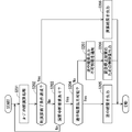
- step S101 the monitoring unit 21 determines whether the calculation time in the automatic operation control unit 20 exceeds the threshold value with respect to the preset calculation time threshold value, and when the calculation time exceeds the threshold value (Yes). In the case of), the automatic operation control unit 20 is notified of the calculation interruption request in step S102. This prevents the calculation time from increasing indefinitely.
- step S103 the control amount switching request is notified to the switching unit 22.
- the monitoring unit 21 notifies the switching unit 22 of the result of determining the safety based on the surrounding environment information obtained from the surrounding environment acquisition units 30 to 32 and the position information obtained from the own vehicle position information acquisition unit 40 ( Step S104).
- the safety judgment is made by the steering control unit 50, the brake control unit 60, and the accelerator control unit 70 even if the control amount of the calculation result in the previous calculation cycle or the control amount of the intermediate result of the calculation is an alternative control amount. , Judgment is made from the viewpoint of whether it can be guaranteed that the situation does not come into contact with obstacles or deviate from the lane, and the judgment result of "safety can be ensured” or "safety cannot be ensured” is notified. Ru.
- the minimum safety can be maintained by using the situation of contacting obstacles and the situation of deviating from the lane as the safety judgment criteria.
- the presence or absence of other vehicles and obstacles and surrounding environment information for example, whether it is a straight road or a curved road, whether there is an intersection, or whether there is a blind spot in the direction of travel. It is possible to make a judgment based on information such as, the target route of the own vehicle, and the current control amount.
- the automatic operation control unit 20 obtains the optimum value of the control amount by repeating the loop calculation, but the threshold value of the calculation time used in step S101 is set shorter than the calculation cycle, for example, the calculation cycle is 100 msec. If there is, the threshold value is set to 90 msec, whereby the time for processing by the automatic operation control unit 20 and output selection by the switching unit 22 is secured. Therefore, even if the calculation process for solving the optimization problem is in the middle of a calculation that has not converged, most of the loop operations have been completed, and the calculation result may be a control amount close to the optimum value. ..
- step S101 If it is determined in step S101 that the calculation time of the automatic operation control unit 20 does not exceed the threshold value (if No), it is determined in step S105 whether or not the calculation of the automatic operation control unit 20 has been completed, and the calculation is performed. If it is completed, a series of processes are completed, and if the calculation is not completed, the process of step S101 is repeated.
- the threshold value of the calculation time is set to a fixed value in advance according to the calculation cycle of the automatic operation control unit 20, it may be a variable value. By setting the threshold value to a variable value, it is possible to secure a large amount of calculation time in the automatic operation control unit 20. It is the monitoring unit 21 that changes the threshold value, and determines the threshold value based on the surrounding environment information, the processing by the automatic operation control unit 20, and the output selection time by the switching unit 22.
- the automatic operation control unit 20 adopts a method of obtaining the optimum value by repeating the loop calculation, and obtains the optimum value by repeating the loop internal calculation process of step S201.
- an optimization method such as a known steepest descent method can be adopted.
- the loop internal calculation process in step S201 is one loop operation out of a plurality of loop operations in the calculation process for solving the optimization problem, and is the loop internal calculation process in step S201, that is, one loop operation. Is completed, it is determined in step S202 whether the calculation end condition is satisfied.
- the calculation end condition in step S202 means that all the calculation processes for solving the optimization problem have been completed, and satisfying this means that the optimum value of the control amount of the actuator has been obtained.
- step S202 When the calculation end condition is achieved in step S202 (in the case of Yes), the calculation result is output in step S206 to end the series of processing. On the other hand, if the calculation end condition cannot be achieved in step S202 (if No), the process proceeds to step S203, and it is confirmed whether the monitoring unit 21 has notified the calculation interruption request.
- the monitoring unit 21 determines whether the calculation time in the automatic operation control unit 20 exceeds the threshold value, and notifies the calculation interruption request when the calculation time exceeds the threshold value.
- the threshold value is set as described above. , The time is set to be slightly shorter than the calculation cycle of the calculation process for solving the optimization problem. Therefore, even if the arithmetic processing for solving the optimization problem does not converge, the monitoring unit 21 does not issue a notification of the arithmetic interruption request unless most of the loop arithmetic is completed. If the monitoring unit 21 has not notified the calculation interruption request (if No), the process returns to step S201 and the next loop internal calculation process is performed.
- step S204 when the operation interruption request is notified from the monitoring unit 21 (in the case of Yes), is it possible to stop the loop internal operation processing and output the control amount of the intermediate result of the operation as an alternative control amount in step S204? To judge.
- This determination is made from the viewpoint of whether or not the control amount has reached a value that can control the vehicle, even if the result is in the middle of the calculation.
- the PID control described above is an example, and the control amount for comparison may be obtained by any conventional calculation.
- step S204 If it is determined in step S204 that the control amount of the intermediate result of the calculation can be output as an alternative control amount (in the case of Yes), the intermediate result is output to the switching unit 22 in step S205.
- step S204 when it is determined that the control amount of the intermediate result of the calculation cannot be output as an alternative control amount (in the case of No), the intermediate result output impossible information is notified to the switching unit 22 in step S207, and then the switching unit 22 is notified.
- step S208 the control amount for the emergency stop measure (emergency stop control amount) is output to the switching unit 22.
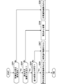
- the switching unit 22 confirms whether the control amount switching request has been notified from the monitoring unit 21 in step S301.
- the control amount switching request has not been notified (in the case of No)
- the control amount of the normal calculation result output from the automatic operation control unit 20 is selected and output in step S305. ..
- step S301 when it is confirmed in step S301 that the control amount switching request has been notified (in the case of Yes), the safety determination result notified from the monitoring unit 21 in step S302 is confirmed. If safety cannot be ensured in step S302 (No), the control amount for emergency stop measures output from the automatic operation control unit 20 is selected as an alternative control amount in step S306. Output. Examples of emergency stop measures include “stop on the shoulder" and "stop on the spot".
- step S302 when the safety determination result is that the safety can be ensured (in the case of Yes), it is confirmed whether the intermediate result output impossible information is sent from the automatic operation control unit 20 (step). S303). When it is confirmed in step S303 that the information that the intermediate result cannot be output is not sent (in the case of No), the control amount of the intermediate result of the calculation is selected in step S307 and output as an alternative control amount.
- step S303 when it is confirmed that the intermediate result output impossible information has been sent (in the case of Yes), the calculation result in the previous calculation cycle stored in the previous value holding unit 23 in step S304 Select the control amount of and output it as an alternative control amount.
- the monitoring unit 21 monitors the calculation time of the automatic driving control unit 20 in synchronization with the calculation of the automatic driving control unit 20, and the calculation time is a control amount. If it does not fall within the calculation cycle time of, the automatic operation control unit 20 is requested to interrupt the calculation, and the switching unit 22 is requested to switch the output of the control amount.
- the switching unit 22 selects the control amount of the intermediate result of the calculation or the control amount calculated in the previous calculation cycle and outputs it as an alternative control amount, so that the calculation load is increased. Even if it increases, the control amount according to the situation can be output to maintain the automatic operation.
- the control amount calculated in the previous calculation cycle is likely to be a control amount relatively close to the control amount in the normal calculation result, and in that case, appropriate automatic operation can be maintained.
- FIG. 5 is a functional block diagram showing the configuration of the vehicle control device 10A according to the second embodiment of the present invention.
- the switching unit 22 is provided with a control history holding unit 24 instead of the previous value holding unit 23, and the vehicle control described with reference to FIG. 1 is provided.
- the same components as those of the device 10 are designated by the same reference numerals, and duplicate description will be omitted.
- the control history holding unit 24 not only stores the control amount output from the automatic operation control unit 20 for each calculation cycle of the control amount as the previous value, but also stores the control amount for a certain period past the previous value as the history value. Store.
- step S401, S402 and S403 are the same as the processes of steps S301, S302 and S303 of the flowchart shown in FIG.
- step S403 the history value stored in the control history holding unit 24 is set in step S404. It differs from the vehicle control device 10 of the first embodiment in that the predicted control amount calculated based on the above is selected and output as an alternative control amount.
- step S404 the predicted control amount calculated from the past historical value is used as an alternative control amount. Can be output as. Therefore, it is possible to output an alternative control amount according to the vehicle state and surrounding environment information rather than the control amount calculated in the previous calculation cycle.
- steps S405, S406 and S407 is the same as the processing of steps S305, S306 and S307 of the flowchart shown in FIG.
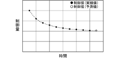
- FIG. 7 is a diagram illustrating an example of a method of determining the predicted control amount with reference to the past history value stored in the control history holding unit 24.
- FIG. 7 is a diagram showing the past control amount in chronological order, the horizontal axis shows the passage of time, the vertical axis shows the control amount, ⁇ is the past control amount which is the actual value, and ⁇ is the past control amount. It is a predicted value (predicted control amount) calculated from the control amount by extrapolation, and in step S404, the predicted value is output as an alternative control amount.
- control amount stored in the control history holding unit 24 does not have to be all past controls, and may be thinned out and stored at appropriate intervals.
- the predicted value is not limited to the value extrapolated from the history of the past control amount.
- the engine control amount is less than the predicted value, and the brake control amount is larger than the predicted value. By determining the control amount, the vehicle may be controlled more safely.
- the switching unit 22 determines the control amount during the calculation or the past history value stored in the control history holding unit 24. Since the predicted control amount calculated from is selected and output as an alternative control amount, the actuator can be controlled with a control amount more suitable for the vehicle condition and surrounding environment information, and the accuracy and safety of automatic driving can be further improved. ..
- FIG. 8 is a functional block diagram showing the configuration of the vehicle control device 10B according to the third embodiment of the present invention.
- the difference from the vehicle control device 10A shown in FIG. 5 is that the automatic driving slave system control unit 25 is provided, and the same reference numerals are given to the same configuration as the vehicle control device 10A described with reference to FIG. Is added, and duplicate explanations are omitted.
- the automatic driving slave control unit 25 is a part that functions as a backup so that the operation as an automatic driving vehicle can be continued even if an abnormality such as a failure occurs in the automatic driving control unit 20, and the minimum amount of calculation is small. It is configured to use algorithms that provide safe operation. As with the emergency stop measures, the actions that can ensure the minimum safety include, for example, "stop on the shoulder" and "stop on the spot".
- step S501 for determining whether or not an abnormality has occurred in the automatic operation control unit 20 is provided. Then, in step S501, when it is determined that an abnormality has occurred in the automatic operation control unit 20 (in the case of No), the control amount of the slave system calculation result calculated by the automatic operation slave system control unit 25 in step S506. Is different from the first and second embodiments in that is output as an alternative control amount.
- Whether or not an abnormality has occurred in the automatic operation control unit 20 is determined by, for example, periodically communicating a message with the automatic operation control unit 20 and for a predetermined period with respect to the message transmitted from the switching unit 22. If there is no response message from the automatic operation control unit 20 inside, it can be determined that an abnormality has occurred in the automatic operation control unit 20.
- step S501 determines whether abnormality has occurred in the automatic operation control unit 20 (in the case of Yes)
- step S502 determines whether the control amount switching request has been notified from the monitoring unit 21.
- step S302 determines whether the control amount switching request has not been notified.
- step S502 when it is confirmed in step S502 that the control amount switching request has been notified (in the case of Yes), the safety determination result notified from the monitoring unit 21 in step S503 is confirmed. If safety cannot be ensured in step S503 (No), it is determined whether the slave system calculation result calculated by the automatic operation slave system control unit 25 in step S508 can be output, and the output is possible. In the case of (Yes), the control amount of the slave system calculation result calculated by the automatic operation slave system control unit 25 in step S509 is output as an alternative control amount. On the other hand, if it is determined in step S508 that the slave calculation result cannot be output, in step S510, the control amount for the emergency stop measure output from the automatic operation control unit 20 is selected and the alternative control amount is selected. Output as and implement emergency stop measures. Examples of emergency stop measures include “stop on the shoulder" and "stop on the spot". It differs from embodiments 1 and 2 in that it comprises steps S508 and S509.
- step S508 In the determination of whether the slave calculation result in step S508 can be output, if the control amount changes significantly and the calculation result is such that the vehicle cannot follow, it is determined that the output is not possible, and the control amount changes significantly. If there is no such method, it can be determined that output is possible.
- the change in the control amount can be detected by the difference from the previous control amount stored in the control history holding unit 24, and if the difference exceeds a predetermined threshold value, it is determined that the change in the control amount is large. can do.
- step 503 when the safety determination result is that the safety can be ensured (in the case of Yes), it is confirmed whether the intermediate result output impossible information is sent from the automatic operation control unit 20 (step S504). .. When it is confirmed in step S504 that the information that the intermediate result cannot be output is not sent (in the case of No), the control amount of the intermediate result of the calculation is selected in step S511 and output as an alternative control amount.
- step S504 when it is confirmed that the intermediate result output impossible information has been sent (in the case of Yes), the control calculated from the control history stored in the control history holding unit 24 in step S505. It differs from the vehicle control device 10 of the first embodiment in that the amount is selected and output as an alternative control amount.
- the control amount according to the situation is output and the automatic operation is performed. Has the effect of maintaining.
- the switching unit 22 has the control amount in the middle of calculation or the past control history stored in the control history holding unit 24. Since the control amount of the result calculated from is selected and output as an alternative control amount, the actuator can be controlled with the control amount more suitable for the vehicle condition and the surrounding environment information, and the accuracy and safety of automatic driving can be further improved. it can.
- the control amount of the slave system calculation result calculated by the automatic operation slave system control unit 25 is selected and output as an alternative control amount, so that the automatic operation control Even when an abnormality occurs in the unit 20, the safety of automatic operation can be ensured.
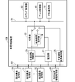
- Each part of the vehicle control devices 10, 10A and 10B of the first to third embodiments described above can be configured by using a computer, and is realized by executing the program by the computer. That is, the vehicle control devices 10, 10A and 10B are realized by, for example, the processing circuit 100 shown in FIG. A processor such as a CPU (Central Processing Unit) or a DSP (Digital Signal Processor) is applied to the processing circuit 100, and the functions of each part are realized by executing a program stored in the storage device.
- a processor such as a CPU (Central Processing Unit) or a DSP (Digital Signal Processor) is applied to the processing circuit 100, and the functions of each part are realized by executing a program stored in the storage device.
- CPU Central Processing Unit
- DSP Digital Signal Processor
- dedicated hardware may be applied to the processing circuit 100.
- the processing circuit 100 may be, for example, a single circuit, a composite circuit, a programmed processor, a parallel programmed processor, an ASIC (Application Specific Integrated Circuit), or an FPGA (Field-Programmable). GateArray), or a combination of these, etc.
- FIG. 11 shows a hardware configuration when the vehicle control devices 10, 10A and 10B are configured by using a processor.
- the functions of each part of the vehicle control device 10, 10A and 10B vehicle control device 10 are realized by a combination with software or the like (software, firmware, or software and firmware).
- the software or the like is described as a program and stored in the memory 120.
- the processor 110 that functions as the processing circuit 100 realizes the functions of each part by reading and executing the program stored in the memory 120 (storage device). That is, it can be said that this program causes the computer to execute the procedure and method of operation of the components of the vehicle control devices 10, 10A and 10B.
- the memory 120 is, for example, non-volatile such as RAM (RandomAccessMemory), ROM (ReadOnlyMemory), flash memory, EPROM (ErasableProgrammableReadOnlyMemory), EEPROM (ElectricallyErasableProgrammableReadOnlyMemory), or the like.
- Volatile semiconductor memory HDD (HardDiskDrive), magnetic disk, flexible disk, optical disk, compact disk, mini disk, DVD (DigitalVersatileDisc) and its drive device, etc., or any storage medium used in the future. You may.
- the present invention is not limited to this, and even if some components of the vehicle control devices 10, 10A and 10B are realized by dedicated hardware and some other components are realized by software or the like. good.
- the function is realized by the processing circuit 100 as dedicated hardware, and for some other components, the processing circuit 100 as the processor 110 is stored in the memory 120. It is possible to realize the function by reading and executing it.
- the vehicle control devices 10, 10A and 10B can realize each of the above-mentioned functions by hardware, software or the like, or a combination thereof.
- each embodiment can be freely combined, and each embodiment can be appropriately modified or omitted within the scope of the invention.
Landscapes
- Engineering & Computer Science (AREA)
- Transportation (AREA)
- Mechanical Engineering (AREA)
- Automation & Control Theory (AREA)
- Human Computer Interaction (AREA)
- Chemical & Material Sciences (AREA)
- Combustion & Propulsion (AREA)
- Control Of Driving Devices And Active Controlling Of Vehicle (AREA)
- Traffic Control Systems (AREA)
Abstract
Description
<装置構成>
図1は、本発明に係る実施の形態1の車両制御装置10の構成を示す機能ブロック図である。車両制御装置10は、車両(図示せず)に搭載され、同じく車両に搭載された複数の周辺環境取得部30、31、32および自車位置情報取得部40から車載ネットワーク80を介して各種情報を受ける自動運転制御部20と、周辺環境取得部30、31、32、自車位置情報取得部40および自動運転制御部20に接続される監視部21と、自動運転制御部20および監視部21に接続される切替部22と、切替部22に車載ネットワーク81を介して接続されるステアリング制御部50、ブレーキ制御部60およびアクセル制御部70を備えている。
まず、図2に示すフローチャートを用いて、監視部21での切り替え判定について説明する。監視部21は自動運転制御部20の演算と同期し、自動運転制御部20の演算時間を監視する。ここで、自動運転を実現するためのアクチュエータの制御量の演算については種々のアルゴリズムがあるが、ここでは最適化問題を解くことで最適値を求めるようなアルゴリズムを用いるものとし、ループ演算を複数回繰り返すことで最適値を求める。このような場合、何度繰り返しても最適値に収束せず、演算時間が大きくなってしまう可能性がある。演算時間が大きくなり過ぎると、いつまで経っても自動運転制御部20から制御量が出力されず、自動運転に支障を来すこととなる。
<装置構成>
図5は、本発明に係る実施の形態2の車両制御装置10Aの構成を示す機能ブロック図である。図1に示した車両制御装置10との相違点は、切替部22において前回値保持部23の代わりに制御履歴保持部24が設けられている点であり、図1を用いて説明した車両制御装置10と同一の構成については同一の符号を付し、重複する説明は省略する。
実施の形態1の車両制御装置10の説明において、図2のフローチャートを用いて説明した監視部21での切り替え判定、図3のフローチャートを用いて説明した自動運転制御部20でのアクチュエータの制御量の演算処理については、実施の形態2の車両制御装置10Aにおいても同じであるが、切替部22での切り替え処理については実施の形態1とは異なっている。
<装置構成>
図8は、本発明に係る実施の形態3の車両制御装置10Bの構成を示す機能ブロック図である。図5に示した車両制御装置10Aとの相違点は、自動運転従系制御部25を備えている点であり、図5を用いて説明した車両制御装置10Aと同一の構成については同一の符号を付し、重複する説明は省略する。
実施の形態1の車両制御装置10の説明において、図2のフローチャートを用いて説明した監視部21での切り替え判定、図3のフローチャートを用いて説明した自動運転制御部20でのアクチュエータの制御量の演算処理については、実施の形態3の車両制御装置10Bにおいても同じであるが、切替部22での切り替え処理については実施の形態1および2とは異なっている。
以上説明した実施の形態1~3の車両制御装置10、10Aおよび10Bの各部はコンピュータを用いて構成することができ、コンピュータがプログラムを実行することで実現される。すなわち、車両制御装置10、10Aおよび10Bは、例えば図10に示す処理回路100により実現される。処理回路100には、CPU(Central Processing Unit)、DSP(Digital Signal Processor)などのプロセッサが適用され、記憶装置に格納されるプログラムを実行することで各部の機能が実現される。
Claims (8)
- 車両の周辺環境情報および位置情報に基づいて自動運転を実行する際の走行経路を決定し、前記走行経路に応じた制御量を演算して出力する自動運転制御部と、
前記自動運転制御部の演算時間を監視する監視部と、
前記自動運転制御部の出力を受け、前記監視部の指示に基づいて前記制御量または前記制御量に代わる代替制御量を出力する切替部と、を備え、
前記監視部は、
前記演算時間が閾値を超えた場合に、前記自動運転制御部に演算の中断要求を通知し、前記切替部に制御量切り替え要求を通知し、前記周辺環境情報および前記位置情報に基づいて前記代替制御量であっても前記車両の安全性を確保できるか否かの判断を行って、安全性の判断結果を前記切替部に通知し、
前記切替部は、
少なくとも前記制御量切り替え要求および前記安全性の判断結果に基づいて前記制御量または前記代替制御量を出力する、車両制御装置。 - 前記制御量は、
ループ演算を複数回繰り返して最適値を求めることで取得され、
前記自動運転制御部は、
前記監視部から前記演算の中断要求が通知されるまでに前記最適値が得られない場合は、前記演算の中断要求が通知されることで前記ループ演算を停止し、演算途中の制御量が前記代替制御量として出力可能であるかを判断する、請求項1記載の車両制御装置。 - 前記車両の安全性を確保できるか否かの判断は、
前記車両が、少なくとも障害物に接触する状況および車線を逸脱する状況とならない場合に安全性を確保できると判断される、請求項1記載の車両制御装置。 - 前記自動運転制御部は、
前記演算途中の制御量が前記代替制御量として出力不可と判断される場合は、途中結果出力不可情報を前記切替部に通知し、前記車両を緊急停止させるための緊急停止制御量を出力し、
前記切替部は、
前記制御量切り替え要求が通知され、
前記安全性の判断結果が前記車両の安全性を確保できるとされる場合は、
前記代替制御量として前記緊急停止制御量を出力する、請求項2記載の車両制御装置。 - 前記自動運転制御部は、
前記演算途中の制御量が前記代替制御量として出力可能と判断される場合は、前記演算途中の制御量を出力し、
前記切替部は、
前記制御量切り替え要求が通知され、
前記安全性の判断結果が前記車両の安全性を確保できるとされる場合は、
前記代替制御量として前記演算途中の制御量を出力する、請求項2記載の車両制御装置。 - 前記自動運転制御部は、
前記演算途中の制御量が前記代替制御量として出力不可と判断される場合は、途中結果出力不可情報を前記切替部に通知し、
前記切替部は、
前記自動運転制御部から出力された前回の演算周期での前回の制御量を前回値として格納する前回値保持部を有し、
前記制御量切り替え要求が通知され、
前記安全性の判断結果が前記車両の安全性を確保できるとされる場合であって、前記自動運転制御部から前記途中結果出力不可情報が通知されている場合は、
前記代替制御量として前記前回値保持部に格納された前記前回値を出力する、請求項2記載の車両制御装置。 - 前記自動運転制御部は、
前記演算途中の制御量が前記代替制御量として出力不可と判断される場合は、途中結果出力不可情報を前記切替部に通知し、
前記切替部は、
前記自動運転制御部から出力された過去の複数回の演算周期での複数の制御量を履歴値として格納する制御履歴保持部を有し、
前記制御量切り替え要求が通知され、
前記安全性の判断結果が前記車両の安全性を確保できるとされる場合であって、前記自動運転制御部から前記途中結果出力不可情報が通知されている場合は、
前記代替制御量として前記制御履歴保持部に格納された前記履歴値に基づいて得られた予測制御量を出力する、請求項2記載の車両制御装置。 - 前記自動運転制御部を代替する自動運転従系制御部をさらに備え、
前記切替部は、
前記自動運転制御部に異常が発生しているかを判断し、異常が発生していると判断される場合は、
前記代替制御量として前記自動運転従系制御部で演算された従系演算結果の制御量を出力する、請求項2記載の車両制御装置。
Priority Applications (5)
| Application Number | Priority Date | Filing Date | Title |
|---|---|---|---|
| PCT/JP2019/047469 WO2021111554A1 (ja) | 2019-12-04 | 2019-12-04 | 車両制御装置 |
| CN201980102608.6A CN114765976B (zh) | 2019-12-04 | 2019-12-04 | 车辆控制装置 |
| JP2021562258A JP7199572B2 (ja) | 2019-12-04 | 2019-12-04 | 車両制御装置 |
| DE112019007937.9T DE112019007937B4 (de) | 2019-12-04 | 2019-12-04 | Fahrzeug-steuerungseinrichtung |
| US17/767,451 US12384416B2 (en) | 2019-12-04 | 2019-12-04 | Vehicle control device |
Applications Claiming Priority (1)
| Application Number | Priority Date | Filing Date | Title |
|---|---|---|---|
| PCT/JP2019/047469 WO2021111554A1 (ja) | 2019-12-04 | 2019-12-04 | 車両制御装置 |
Publications (1)
| Publication Number | Publication Date |
|---|---|
| WO2021111554A1 true WO2021111554A1 (ja) | 2021-06-10 |
Family
ID=76222603
Family Applications (1)
| Application Number | Title | Priority Date | Filing Date |
|---|---|---|---|
| PCT/JP2019/047469 Ceased WO2021111554A1 (ja) | 2019-12-04 | 2019-12-04 | 車両制御装置 |
Country Status (5)
| Country | Link |
|---|---|
| US (1) | US12384416B2 (ja) |
| JP (1) | JP7199572B2 (ja) |
| CN (1) | CN114765976B (ja) |
| DE (1) | DE112019007937B4 (ja) |
| WO (1) | WO2021111554A1 (ja) |
Citations (4)
| Publication number | Priority date | Publication date | Assignee | Title |
|---|---|---|---|---|
| JP2017157067A (ja) * | 2016-03-03 | 2017-09-07 | 三菱電機株式会社 | 自動運転制御装置 |
| WO2019082647A1 (ja) * | 2017-10-24 | 2019-05-02 | 日立オートモティブシステムズ株式会社 | 車両制御装置 |
| JP2019089382A (ja) * | 2017-11-13 | 2019-06-13 | 株式会社デンソー | 自動運転制御装置、車両の自動運転制御方法 |
| JP2019185246A (ja) * | 2018-04-05 | 2019-10-24 | 三菱電機株式会社 | 自動運転制御システム |
Family Cites Families (9)
| Publication number | Priority date | Publication date | Assignee | Title |
|---|---|---|---|---|
| JPS5846342B2 (ja) | 1980-11-14 | 1983-10-15 | 新技術開発事業団 | セラミツク球の製造法 |
| DE10206865C1 (de) * | 2002-02-18 | 2003-05-15 | Daimler Chrysler Ag | Reaktionszeit-Beschränkung eines Software-Prozesses |
| WO2016046931A1 (ja) | 2014-09-25 | 2016-03-31 | 日本精工株式会社 | 車載用電子機器の制御装置及び制御方法 |
| JP2016113092A (ja) | 2014-12-17 | 2016-06-23 | トヨタ自動車株式会社 | 車両制御装置 |
| JP6654641B2 (ja) * | 2015-10-06 | 2020-02-26 | 株式会社日立製作所 | 自動運転制御装置および自動運転制御方法 |
| JP6726903B2 (ja) * | 2017-03-02 | 2020-07-22 | パナソニックIpマネジメント株式会社 | 運転支援方法およびそれを利用した運転支援装置、自動運転制御装置、車両、プログラム、運転支援システム |
| CN108445885A (zh) * | 2018-04-20 | 2018-08-24 | 鹤山东风新能源科技有限公司 | 一种基于纯电动物流车的自动驾驶系统及其控制方法 |
| US11341356B2 (en) * | 2018-06-15 | 2022-05-24 | Uatc, Llc | System and method for determining object intention through visual attributes |
| CN109606346A (zh) * | 2018-12-29 | 2019-04-12 | 武汉超控科技有限公司 | 一种自动驾驶的车道保持系统 |
-
2019
- 2019-12-04 WO PCT/JP2019/047469 patent/WO2021111554A1/ja not_active Ceased
- 2019-12-04 DE DE112019007937.9T patent/DE112019007937B4/de active Active
- 2019-12-04 JP JP2021562258A patent/JP7199572B2/ja active Active
- 2019-12-04 US US17/767,451 patent/US12384416B2/en active Active
- 2019-12-04 CN CN201980102608.6A patent/CN114765976B/zh active Active
Patent Citations (4)
| Publication number | Priority date | Publication date | Assignee | Title |
|---|---|---|---|---|
| JP2017157067A (ja) * | 2016-03-03 | 2017-09-07 | 三菱電機株式会社 | 自動運転制御装置 |
| WO2019082647A1 (ja) * | 2017-10-24 | 2019-05-02 | 日立オートモティブシステムズ株式会社 | 車両制御装置 |
| JP2019089382A (ja) * | 2017-11-13 | 2019-06-13 | 株式会社デンソー | 自動運転制御装置、車両の自動運転制御方法 |
| JP2019185246A (ja) * | 2018-04-05 | 2019-10-24 | 三菱電機株式会社 | 自動運転制御システム |
Also Published As
| Publication number | Publication date |
|---|---|
| DE112019007937B4 (de) | 2025-05-22 |
| CN114765976A (zh) | 2022-07-19 |
| US12384416B2 (en) | 2025-08-12 |
| US20240075956A1 (en) | 2024-03-07 |
| JPWO2021111554A1 (ja) | 2021-06-10 |
| CN114765976B (zh) | 2025-05-09 |
| DE112019007937T5 (de) | 2022-10-27 |
| JP7199572B2 (ja) | 2023-01-05 |
Similar Documents
| Publication | Publication Date | Title |
|---|---|---|
| JP6611664B2 (ja) | 自動運転制御装置および自動運転制御方法 | |
| KR102138979B1 (ko) | 차선 기반의 확률론적 주변 차량 거동 예측 및 이를 이용한 종방향 제어 방법 | |
| JP7171708B2 (ja) | 複数の制御車線を用いた自律車両の耐障害制御 | |
| US11332157B2 (en) | Vehicle control apparatus | |
| CN115701295B (zh) | 用于车辆路径规划的方法和系统 | |
| US20250065919A1 (en) | Automated driving systems for supporting driving mode transition | |
| JP5104640B2 (ja) | 走行制御装置及び走行制御システム | |
| CN110356413B (zh) | 用于提供车辆的安全策略的装置及方法 | |
| US20180113448A1 (en) | Vehicle energy reduction | |
| US11403949B2 (en) | System for predicting vehicle behavior | |
| CN110371101A (zh) | 用于提供车辆的安全策略的装置及方法 | |
| GB2547510A (en) | Vehicle mode determination | |
| CN117341694A (zh) | 控制车辆变道 | |
| US20180158260A1 (en) | Steering operation | |
| JP6227104B1 (ja) | メモリ診断装置、車両制御装置、メモリ診断方法および車両制御方法 | |
| US12024168B2 (en) | Vehicle for tracking speed profile and control method thereof | |
| WO2021111554A1 (ja) | 車両制御装置 | |
| EP4166408A1 (en) | Advanced driver assistance system for determining a future glare condition and corresponding method | |
| CN115667043B (zh) | 车辆控制系统、车辆综合控制装置、电子控制装置、网络通信装置、车辆控制方法以及计算机可读取的存储介质 | |
| US20240174263A1 (en) | Vehicle control system | |
| WO2019244366A1 (ja) | 自動運転支援システム及びその動作方法 | |
| JP7213935B1 (ja) | 自動運転制御装置、及び、自動運転制御方法 | |
| JP6689337B2 (ja) | 自動運転制御装置および自動運転制御方法 | |
| US20220324447A1 (en) | Vehicle, program and notification method | |
| JP2023069180A (ja) | 車両制御装置及び車両制御方法 |
Legal Events
| Date | Code | Title | Description |
|---|---|---|---|
| 121 | Ep: the epo has been informed by wipo that ep was designated in this application |
Ref document number: 19955081 Country of ref document: EP Kind code of ref document: A1 |
|
| ENP | Entry into the national phase |
Ref document number: 2021562258 Country of ref document: JP Kind code of ref document: A |
|
| WWE | Wipo information: entry into national phase |
Ref document number: 17767451 Country of ref document: US |
|
| 122 | Ep: pct application non-entry in european phase |
Ref document number: 19955081 Country of ref document: EP Kind code of ref document: A1 |
|
| WWG | Wipo information: grant in national office |
Ref document number: 201980102608.6 Country of ref document: CN |
|
| WWG | Wipo information: grant in national office |
Ref document number: 112019007937 Country of ref document: DE |
|
| WWG | Wipo information: grant in national office |
Ref document number: 17767451 Country of ref document: US |