WO2021106789A1 - 検出方法、検出装置、記録媒体および皮膚電位センサ - Google Patents
検出方法、検出装置、記録媒体および皮膚電位センサ Download PDFInfo
- Publication number
- WO2021106789A1 WO2021106789A1 PCT/JP2020/043416 JP2020043416W WO2021106789A1 WO 2021106789 A1 WO2021106789 A1 WO 2021106789A1 JP 2020043416 W JP2020043416 W JP 2020043416W WO 2021106789 A1 WO2021106789 A1 WO 2021106789A1
- Authority
- WO
- WIPO (PCT)
- Prior art keywords
- skin potential
- user
- detection method
- potential level
- skin
- Prior art date
- Legal status (The legal status is an assumption and is not a legal conclusion. Google has not performed a legal analysis and makes no representation as to the accuracy of the status listed.)
- Ceased
Links
Images




Classifications
-
- A—HUMAN NECESSITIES
- A61—MEDICAL OR VETERINARY SCIENCE; HYGIENE
- A61B—DIAGNOSIS; SURGERY; IDENTIFICATION
- A61B5/00—Measuring for diagnostic purposes; Identification of persons
- A61B5/24—Detecting, measuring or recording bioelectric or biomagnetic signals of the body or parts thereof
-
- A—HUMAN NECESSITIES
- A61—MEDICAL OR VETERINARY SCIENCE; HYGIENE
- A61B—DIAGNOSIS; SURGERY; IDENTIFICATION
- A61B5/00—Measuring for diagnostic purposes; Identification of persons
- A61B5/05—Detecting, measuring or recording for diagnosis by means of electric currents or magnetic fields; Measuring using microwaves or radio waves
-
- A—HUMAN NECESSITIES
- A61—MEDICAL OR VETERINARY SCIENCE; HYGIENE
- A61B—DIAGNOSIS; SURGERY; IDENTIFICATION
- A61B5/00—Measuring for diagnostic purposes; Identification of persons
- A61B5/16—Devices for psychotechnics; Testing reaction times ; Devices for evaluating the psychological state
Definitions
- the present invention relates to a detection method, a detection device, a recording medium, and a skin potential sensor.
- the technology to prevent falling asleep using the skin potential is known.
- Patent Document 1 is a document that describes a technique for preventing falling asleep using a skin potential.
- the low wakefulness detection unit detects a low wakefulness state in which the driver is drowsy when the skin potential detected by the skin potential sensor is relatively high.
- Patent Document 1 discloses, as a specific example, that a threshold value for separating a low awake state and an awake state is set, and when the skin potential is equal to or higher than the threshold value, the low awake state is determined. ..
- Patent Document 1 The skin potential described in Patent Document 1 is said to have a strong tendency to be awake when the skin potential is relatively low, and a strong tendency to be in a low awake state when the skin potential is relatively high. It is the skin potential level of the skin potential that has such a tendency. Therefore, it is considered that Patent Document 1 describes a technique for the skin potential level among the skin potentials.
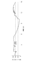
- the skin potential level (SPL: skin potential level) may be instantaneously lowered in response to the appearance of sweating in the palm. Therefore, for example, as shown by the circles in FIG. 1, simply setting the threshold value may erroneously detect the momentary decrease as a state of feeling drowsy. As a result, there has been a problem that it is difficult to accurately predict doze.
- an object of the present invention is to provide a detection method, a detection device, and a program that solve the problem that it is difficult to accurately predict doze.
- the above-mentioned momentary change can be eliminated by setting the cutoff frequency of the low-pass filter low, for example.
- the cutoff frequency of the low-pass filter is set low, the change in the numerical value becomes gentle and the immediacy of detection is lost. Therefore, it is difficult to adopt the above method.
- the detection method which is one embodiment of the present invention, in order to achieve such an object
- the detection device that detects the user's status is Obtain information indicating the skin potential level including the DC component of skin potential activity, The state of the user is detected based on the change in the skin potential level.
- the detection device is A detection device that detects the user's condition.
- An acquisition unit that acquires information indicating the skin potential level including the DC component of the skin potential activity, and A detection unit that detects the user's condition based on the change in the skin potential level acquired by the acquisition unit, and a detection unit. It has a structure of having.
- the recording medium which is another form of the present invention is For the detection device that detects the user's condition, An acquisition unit that acquires information indicating the skin potential level including the DC component of the skin potential activity, and A detection unit that detects the user's condition based on the change in the skin potential level acquired by the acquisition unit, and a detection unit. It is a computer-readable recording medium on which a program for realizing the above is recorded.
- the skin potential sensor which is another embodiment of the present invention, is A skin potential sensor that measures at least the skin potential level. It contains a first electrode and a second electrode that induce the electric potential of the skin.
- the first electrode is arranged on the palm or sole of the user, and the second electrode is arranged on the medial side of the user's forearm, the back of the hand, the ankle joint, or the back of the foot.
- the present invention can provide a detection method, a detection device, a program, and a skin potential sensor that solve the problem that it is difficult to accurately predict doze by being configured as described above.
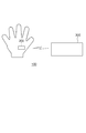
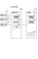
- FIG. 2 is a diagram showing an example of the configuration of the detection system 100.
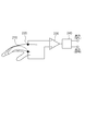
- FIG. 3 is a diagram showing an example of the configuration of the skin potential sensor 200.
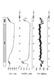
- FIG. 4 is a diagram showing an example of the relationship between SPL, sweating of the palm portion, and RR interval.
- FIG. 5 is a diagram showing an example of the relationship between SPL, sweating of the palm portion, and ⁇ wave frequency.
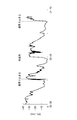
- FIG. 6 is a diagram showing an example of a change in the skin potential level during night driving.
- FIG. 7 is a block diagram showing an example of the configuration of the detection device 300.
- FIG. 8 is a diagram showing an example of a change in the skin potential level.
- FIG. 9 is a diagram showing an example of changes in skin potential reflex.
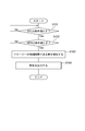
- FIG. 10 is a flowchart showing an example of the operation of the detection device 300.
- the detection system 100 including the detection device 300 that detects the user's state by performing analysis based on the measurement result by the skin potential sensor 200 will be described.
- the detection device 300 includes a skin potential level (SPL: skin potential level) including a DC component of skin potential activity (SPA: skin potential activitiy) and an AC component of skin potential activity (including a DC component). (Not) Obtain skin potential reflex (SPR: skin potential reflex). Then, the detection device 300 detects the state of the user based on the skin potential level and the skin potential reflex. For example, the detection device 300 detects the initial stage of Drowsy based on the degree of change between the skin potential level and the skin potential reflex. By detecting the initial stage of the draw, it is possible to accurately predict doze.
- SPL skin potential level
- SPA skin potential activitiy
- AC component of skin potential activity including a DC component
- SPR skin potential reflex
- drawsy is a medical expression of a drowsy state, a vague state, etc.
- a drawsy state is a state in which there is a risk of falling asleep. For example, in dangerous work such as driving a car, a drawsy state causes a serious accident. Further, for example, in office work, the work efficiency is lowered in the drawsy state.
- FIG. 2 is a diagram showing an example of the overall configuration of the detection system 100.
- the detection system 100 includes, for example, a skin potential sensor 200 and a detection device 300.
- the skin potential sensor 200 and the detection device 300 are connected so as to be able to communicate with each other by wireless communication such as Wi-Fi (registered trademark) or Bluetooth (registered trademark).
- the skin potential sensor 200 and the detection device 300 may be connected to each other by wire, for example, so as to be able to communicate with each other.
- the skin potential sensor 200 is attached to the user's hand or the like.
- the skin potential sensor 200 has electrodes and the like, and measures the skin potential level and the skin potential reflex.
- the skin potential sensor 200 has a function of communicating with the detection device 300 by wireless communication, for example.
- the skin potential sensor 200 transmits information indicating the skin potential level, which is a measurement result, and information indicating the skin potential reflection to the detection device 300 by wireless communication.
- FIG. 3 shows a configuration example of a portion of the skin potential sensor 200 that measures the skin potential level and the skin potential reflex.
- the skin potential sensor 200 uses, for example, an electrode 210 and an electrode 220 for inducing a skin potential, a differential amplifier (amplifier) 230, and a skin potential level and a skin potential reflection from the induced potential. It is composed of a filter 240 to be extracted and a filter 240 to be extracted.
- the positions of the electrodes 210 and 220 affect the value of the skin potential level. Therefore, the positions of the electrodes 210 and 220 must be carefully selected. For example, as shown in FIG. 3, the electrode 210 is arranged on the palm portion, and the electrode 220 is arranged on the inside of the forearm or the back of the hand. By arranging the electrodes 210 and 220 in this way, it is possible to appropriately evaluate the skin potential level. That is, in order to measure the skin potential level with high accuracy, it is preferable to arrange the electrode 210 on the palm and the electrode 220 on the inside of the forearm or the back of the hand.
- the skin potential level can be measured from the sole of the foot.
- the electrode 210 is placed on the sole of the foot, and the electrode 220 is placed on the ankle joint or the back of the foot.
- the electrodes 210 and 220 conductive fibers and the like can be used as well as electrodes for electrocardiography composed of Ag / AgCl electrodes and adhesive gel or paste.
- the skin potential sensor 200 may be realized as, for example, gloves, socks, sandals, or the like.
- the filter 240 separates the skin potential into a skin potential level containing a DC component and a skin potential reflex containing no DC component.
- the baseline of the skin potential level that should be noted in order to realize doze prediction is approximately 0.04 Hz or less. Therefore, it is desirable that the filter 240 is a filter that extracts components of about 0.04 Hz or less.
- the skin potential level is a value including the DC component of the skin potential activity.
- the skin potential level is a long-term variable component of skin potential activity.
- SPL skin potential level
- FIG. 4 shows the results of comparing the skin potential level (SPL) when the eyes are closed, the change in palm sweating, and the RR interval indicating the interval between R waves.
- the upper graph of FIG. 4 shows the skin potential level
- the middle graph of FIG. 4 shows the change in palm sweating
- the lower graph of FIG. 4 shows the RR interval. ..
- FIG. 5 shows the results of comparing the skin potential level (SPL) when the eyes are closed, the change in palm sweating, and the electroencephalogram ( ⁇ wave frequency).
- SPL skin potential level
- ⁇ wave frequency the electroencephalogram
- the upper graph of FIG. 5 shows the skin potential level
- the middle graph of FIG. 5 shows the change in palm sweating
- the lower graph of FIG. 5 shows the electroencephalogram (alpha wave frequency).
- the ⁇ wave frequency of brain waves increases and the RR interval decreases.
- FIGS. 4 and 5 it can be seen that the phenomenon in which the baseline of the skin potential level changes and the negative potential approaches zero occurs in synchronization with the increase in the ⁇ wave frequency and the decrease in the RR interval. That is, referring to FIGS. 4 and 5, the baseline of the skin potential level changes and is negative when the ⁇ wave frequency and RR interval of the brain wave indicate that the brain wave is in a resting state (or a drawsy state). It can be seen that the potential of is approaching zero.
- FIG. 6 shows an example of a change in the skin potential level during driving a car during night driving. With reference to FIG. 6, it can be seen that the baseline change of the skin potential level occurs even during night driving.
- the skin potential reflex is an AC component of skin potential activity.
- the cutaneous potential reflex reacts instantaneously in response to an external stimulus or the like.
- the above is an example of the configuration of the skin potential sensor 200.
- the skin potential sensor 200 may be attached and fixed to the user's hand or the like in advance by the mechanism as described above, or may be provided at a place where the user's hand comes into contact, such as the steering wheel of an automobile.
- the detection device 300 is an information processing device that detects the user's state such as the initial stage of drawing by performing analysis based on the measurement result by the skin potential sensor 200.
- the function as the detection device 300 may be, for example, possessed by an independent information processing device, or may be possessed by an in-vehicle device such as a car navigation device.
- FIG. 7 shows an example of the configuration of the detection device 300.
- the detection device 300 has a screen display unit 310, an audio output unit 320, a communication I / F unit 330, a storage unit 340, and an arithmetic processing unit 350 as main components. doing.
- the screen display unit 310 includes a screen display device such as an LCD (Liquid Crystal Display).
- the screen display unit 310 can display warning information and the like on the screen in response to an instruction from the arithmetic processing unit 350.
- the audio output unit 320 includes a device that outputs audio such as a microphone, a speaker, headphones, and earphones.
- the audio output unit 320 can output warning information and the like in response to an instruction from the arithmetic processing unit 350.
- the communication I / F unit 330 includes a data communication circuit.
- the communication I / F unit 330 performs data communication with various devices connected via a communication line.
- the detection device 300 receives information indicating the skin potential level and information indicating the skin potential reflection from the skin potential sensor 200 via the communication I / F unit 330.
- the storage unit 340 is a storage device such as a hard disk or a memory.
- the storage unit 340 stores processing information and a program 343 required for various processes in the arithmetic processing unit 350.
- the program 343 realizes various processing units by being read and executed by the arithmetic processing unit 350.
- the program 343 is read in advance from an external device or a recording medium via a data input / output function such as the communication I / F unit 330, and is stored in the storage unit 340.
- the main information stored in the storage unit 340 includes, for example, skin potential level information 341 and skin potential reflection information 342.
- the arithmetic processing unit 350 has a microprocessor such as an MPU and its peripheral circuits.
- the arithmetic processing unit 350 reads the program 343 from the storage unit 340 and executes it, thereby realizing various processing units in cooperation with the hardware and the program 343.
- the main processing units realized by the arithmetic processing unit 350 include, for example, a measurement result acquisition unit 351, a state detection unit 352, and a warning unit 353.
- the measurement result acquisition unit 351 acquires from the skin potential sensor 200 information indicating the skin potential level and information indicating the skin potential reflection, which are the measurement results of the skin potential sensor 200. Then, the measurement result acquisition unit 351 stores the acquired information indicating the skin potential level in the storage unit 340 as the skin potential level information 341, and stores the acquired information indicating the skin potential reflection as the skin potential reflection information 342 in the storage unit 340. Store in.
- the state detection unit 352 detects the user's state based on the skin potential level indicated by the skin potential level information 341 and the skin potential reflection indicated by the skin potential reflection information 342. For example, the state detection unit 352 detects that the user is in the initial stage of drawing based on the skin potential level and the skin potential reflex.
- the state detection unit 352 confirms the degree of change in the skin potential level. Then, the state detection unit 352 determines that the user may be in the initial stage of drawing when it is determined that the change in the skin potential level satisfies a predetermined condition.
- the state detection unit 352 calculates the rate of change (slope) at each point, such as every second. That is, the state detection unit 352 calculates the slope, which is a value indicating the degree of change in the skin potential level with the passage of time, for each point. Then, the state detection unit 352 confirms whether or not a period in which the calculated slope is equal to or greater than a predetermined value (arbitrary value is acceptable) continues for a predetermined period (arbitrary period such as 10 seconds or 30 seconds). To confirm the degree of change in the skin potential level. When the inclination is equal to or greater than a predetermined value for a predetermined period of time, the state detection unit 352 determines that the user may be in the initial stage of drawing.
- a predetermined value arbitrary value is acceptable
- the state detection unit 352 confirms, for example, the skin potential reflex described later. On the other hand, when the period in which the inclination is equal to or greater than the predetermined value does not continue for a predetermined period, the state detection unit 352 determines that the user is unlikely to be in the initial stage of drawing.
- FIG. 8 shows an example of the skin potential level indicated by the skin potential level information 341.
- the value of the skin potential level continuously approaches 0 between about 5 minutes and 30 seconds and about 6 minutes and 30 seconds, and between about 6 minutes and 30 seconds and after 10 minutes.
- the slope of each point is large.
- the state detection unit 352 can determine that the user may be in the initial stage of drawing.
- the state detection unit 352 determines whether or not the user may be in the initial stage of drawing based on the degree of change in the skin potential level. In other words, the state detection unit 352 determines whether or not the value of the skin potential level may be in the initial stage of drawing depending on whether or not the value of the skin potential level is continuously approaching 0 for a predetermined period. You can also do it.
- the state detection unit 352 confirms the change in the skin potential reflex when it determines that the drawsy may be in the initial stage based on the skin potential level. Then, when it is determined that the change in the skin potential reflex satisfies a predetermined condition, the state detection unit 352 detects that it is the initial stage of the drawsy.
- the state detection unit 352 determines whether or not an amplitude of a predetermined value or more is confirmed in the skin potential reflex during a predetermined period (or whether or not the number and frequency of amplitudes are 1 or less, such as 1 or less). (Whether or not) Confirm. Then, when an amplitude of a predetermined value or more is not confirmed in the skin potential reflection for a predetermined period, the state detection unit 352 detects that it is the initial stage of the drawsy. On the other hand, when an amplitude of a predetermined value or more is confirmed in the skin potential reflection, the state detection unit 352 does not detect that it is in the initial stage of drawing.
- FIG. 9 shows an example of the skin potential reflection indicated by the skin potential reflection information 342.
- the state detection unit 352 can detect that it is in the initial stage of drawing, for example, within the above period.
- the state detection unit 352 detects that the drawsy is in the initial stage based on the change in the skin potential reflex. In other words, the state detection unit 352 detects that the drawsy is in the initial stage depending on whether or not the value of the skin potential reflex is 0 (or less than the predetermined value) continuously for a predetermined period. You can also say that.
- the predetermined period for confirming the skin potential reflex is, for example, the same period as the predetermined period for confirming the skin potential reflex.
- the predetermined period for confirming the cutaneous potential reflex may be a predetermined period (arbitrary period) after confirming the cutaneous potential reflex.
- the state detection unit 352 detects that the drawsy is in the initial stage based on the change in the skin potential level and the change in the skin potential reflex. Then, when it is detected that it is the initial stage of the drawsy, the state detection unit 352 notifies the warning unit 353 that it has detected that it is the initial stage of the drawsy.
- the warning unit 353 issues a predetermined warning when the state detection unit 352 determines that it is in the initial stage of drawing. For example, the warning unit 353 gives a warning by displaying the warning information indicating that the drawing is in the initial stage on the screen display unit 310 or outputting the warning information via the voice output unit 320.
- the warning unit 353 may be configured to give a warning by a method other than the above-exemplified method, such as transmitting warning information to an external device via the communication I / F unit 330 or vibrating a smartphone or the like owned by the user. Absent.
- the state detection unit 352 of the detection device 300 confirms whether or not the change in the skin potential level satisfies a predetermined condition (step S101). For example, the state detection unit 352 calculates the rate of change at each point, such as every second, and confirms whether or not the calculated slope continues for a predetermined period of time or more.
- step S101, No When the change in the skin potential level does not satisfy the predetermined condition (step S101, No), the state detection unit 352 continues to confirm the change in the skin potential level.
- step S101, Yes when the change in the skin potential level satisfies a predetermined condition (step S101, Yes), the state detection unit 352 confirms whether or not the change in the skin potential reflex satisfies the predetermined condition (step S102). For example, the state detection unit 352 confirms whether or not an amplitude of a predetermined value or more is confirmed in the skin potential reflex during a predetermined period.
- step S102, No When the change in the skin potential reflex does not satisfy the predetermined condition (step S102, No), the state detection unit 352 returns to the confirmation of the change in the skin potential level.
- step S102, Yes when the change in the skin potential reflex satisfies a predetermined condition (step S102, Yes), the state detection unit 352 detects that it is in the initial stage of the draw (step S103). Then, the state detection unit 352 notifies the warning unit 353 that it has detected that it is in the initial stage of the drawsy.
- Warning unit 353 warns that it is in the initial stage of drawing (step S104). For example, the warning unit 353 gives a warning by displaying the warning information on the screen display unit 310 or outputting the warning information via the voice output unit 320.
- the above is an example of the operation of the detection device 300.
- the detection device 300 has a measurement result acquisition unit 351 and a state detection unit 352.
- the state detection unit 352 can detect that it is the initial stage of the drawsy based on the change in the skin potential level and the change in the skin potential reflex acquired by the measurement result acquisition unit 351. it can. In this way, by detecting that the draw is in the initial stage based on the change in the skin potential level and the change in the skin potential reflex, it is possible to reduce erroneous detection due to a momentary decrease in the skin potential level. .. As a result, it is possible to accurately detect that it is in the initial stage of drawing, and it is possible to accurately predict doze.
- the skin and the conductive fibers are polarized, and the measured skin potential level is often not a correct value. ..
- the determination is not simply based on the magnitude of the value. Even if there is a problem with the contact condition, it is possible to more accurately detect that it is in the initial stage of drawing.
- the skin potential level value and the skin potential reflection value appear higher or lower depending on the contact condition between the electrodes 210 and 220 and the skin. Even in such a case, it is possible to accurately detect that the drawing is in the initial stage.
- the detection device 300 uses both the change in the skin potential level and the change in the skin potential reflex. In this way, by performing detection based on the change in the skin potential level and the change in the skin potential reflex, even if the period for confirming the skin potential level is shortened, it is more accurately shown that the initial stage of drawing is performed. Can be detected. That is, according to the above configuration, it is possible to accurately detect that the drawsy is in the initial stage while shortening the time until detection.
- the detection device 300 performs detection based on the change in the skin potential level and the change in the skin potential reflex is illustrated.
- the detection device 300 may be configured to detect that it is in the initial stage of drawing by using only one of the change in the skin potential level and the change in the skin potential reflex.
- the detection device 300 may be configured to detect that it is in the initial stage of drawing based on the degree of change in the skin potential level.
- the function as the detection device 300 is realized by one information processing device is illustrated.
- the function as the detection device 300 may be realized by, for example, a plurality of information processing devices connected via a network.
- the detection device 40 is an information processing device that detects the state of the user.
- FIG. 11 shows an example of the configuration of the detection device 40.
- the detection device 40 includes, for example, an acquisition unit 41 and a detection unit 42.
- the detection device 40 has an arithmetic unit such as a CPU (Central Processing Unit) and a storage device.
- the detection device 40 realizes each of the above-mentioned processing units by executing the program stored in the storage device by the arithmetic unit.
- the acquisition unit 41 acquires information indicating the skin potential level including the DC component of the skin potential activity.
- the detection unit 42 detects the user's state based on the change in the skin potential level acquired by the acquisition unit 41.
- the detection device 40 has an acquisition unit 41 and a detection unit 42.
- the detection unit 42 can detect the state of the user based on the degree of change in the skin potential level acquired by the acquisition unit 41. In this way, by detecting the user's state based on the change in the skin potential level, it is possible to reduce erroneous detection due to a momentary decrease in the skin potential level. As a result, the user's state can be detected with high accuracy.
- the above-mentioned detection device 40 can be realized by incorporating a predetermined program into the detection device 40.
- the detection device 40 for detecting the state of the user has an acquisition unit 41 for acquiring information indicating the skin potential level which is a DC component of the skin potential activity, and an acquisition unit 41.
- This is a program for realizing a detection unit that detects a user's state based on a change in the skin potential level acquired by 41.
- the detection device that detects the state of the user acquires information indicating the skin potential level which is a DC component of the skin potential activity, and changes the skin potential level. Based on this, the user's state is detected.
- the detection device that detects the user's status is Obtain information indicating the skin potential level, which is the DC component of skin potential activity, A detection method for detecting a user's condition based on the degree of change in the skin potential level.
- Appendix 2 The detection method described in Appendix 1.
- Appendix 3 The detection method according to Appendix 1 or Appendix 2.
- Appendix 4 The detection method described in Appendix 3 A detection method that detects a user's condition based on a period in which the calculated slope has a magnitude greater than or equal to a predetermined value.
- Appendix 5 The detection method according to any one of Supplementary note 1 to Supplementary note 4. Obtain information indicating the skin potential reflex, which is an AC component of skin potential activity, A detection method for detecting a user's state based on a change in the skin potential level and a change in the skin potential reflex.
- Appendix 6) The detection method according to Appendix 5. A detection method for detecting a user's condition based on a period during which the amplitude of the skin potential reflex is not confirmed.
- Appendix 7 The detection method according to Appendix 5 or Appendix 6. The user feels drowsy when the period in which the slope of the skin potential level is greater than or equal to a predetermined value satisfies the condition and the period in which the amplitude of the skin potential reflex is not confirmed satisfies the condition. A detection method that detects the fact that there is. (Appendix 8) The detection method according to any one of Supplementary note 1 to Supplementary note 7. A detection method that gives a warning according to the state of the detected user. (Appendix 9) The detection method according to any one of Supplementary note 1 to Supplementary note 8. A detection method that detects that the user's condition is in the initial stage of drawing.
- a detection device that detects the user's condition.
- An acquisition unit that acquires information indicating the skin potential level, which is a DC component of skin potential activity,
- a detection unit that detects the user's condition based on the change in the skin potential level acquired by the acquisition unit, and a detection unit.
- Detection device with. (Appendix 11)
- An acquisition unit that acquires information indicating the skin potential level, which is a DC component of skin potential activity,
- a detection unit that detects the user's condition based on the change in the skin potential level acquired by the acquisition unit, and a detection unit.
- a computer-readable recording medium that records programs to achieve this.
- a skin potential sensor that measures at least the skin potential level. It contains a first electrode and a second electrode that induce the electric potential of the skin.
- a skin potential sensor in which the first electrode is placed on the palm of the user and the second electrode is placed on the inside of the user's forearm or the back of the hand.
- the programs described in each of the above embodiments and appendices may be stored in a storage device or recorded in a computer-readable recording medium.
- the recording medium is a portable medium such as a flexible disk, an optical disk, a magneto-optical disk, and a semiconductor memory.
- Detection system 100 Detection system 200 Skin potential sensor 210 Electrode 220 Electrode 230 Differential amplifier 240 Filter 300 Detection device 310 Screen display unit 320 Voice output unit 330 Communication I / F unit 340 Storage unit 341 Skin potential level information 342 Skin potential reflection information 350 Arithmetic processing Unit 351 Measurement result acquisition unit 352 Status detection unit 353 Warning unit 40 Detection device 41 Acquisition unit 42 Detection unit
Landscapes
- Health & Medical Sciences (AREA)
- Life Sciences & Earth Sciences (AREA)
- Engineering & Computer Science (AREA)
- Animal Behavior & Ethology (AREA)
- Heart & Thoracic Surgery (AREA)
- Veterinary Medicine (AREA)
- Public Health (AREA)
- General Health & Medical Sciences (AREA)
- Surgery (AREA)
- Physics & Mathematics (AREA)
- Molecular Biology (AREA)
- Biophysics (AREA)
- Pathology (AREA)
- Biomedical Technology (AREA)
- Medical Informatics (AREA)
- Educational Technology (AREA)
- Developmental Disabilities (AREA)
- Social Psychology (AREA)
- Child & Adolescent Psychology (AREA)
- Psychology (AREA)
- Psychiatry (AREA)
- Hospice & Palliative Care (AREA)
- Nuclear Medicine, Radiotherapy & Molecular Imaging (AREA)
- Radiology & Medical Imaging (AREA)
- Measurement And Recording Of Electrical Phenomena And Electrical Characteristics Of The Living Body (AREA)
- Measurement Of The Respiration, Hearing Ability, Form, And Blood Characteristics Of Living Organisms (AREA)
Priority Applications (1)
| Application Number | Priority Date | Filing Date | Title |
|---|---|---|---|
| JP2021561382A JP7207839B2 (ja) | 2019-11-26 | 2020-11-20 | 検出方法、検出装置、プログラム |
Applications Claiming Priority (2)
| Application Number | Priority Date | Filing Date | Title |
|---|---|---|---|
| JP2019-213017 | 2019-11-26 | ||
| JP2019213017 | 2019-11-26 |
Publications (1)
| Publication Number | Publication Date |
|---|---|
| WO2021106789A1 true WO2021106789A1 (ja) | 2021-06-03 |
Family
ID=76130223
Family Applications (1)
| Application Number | Title | Priority Date | Filing Date |
|---|---|---|---|
| PCT/JP2020/043416 Ceased WO2021106789A1 (ja) | 2019-11-26 | 2020-11-20 | 検出方法、検出装置、記録媒体および皮膚電位センサ |
Country Status (2)
| Country | Link |
|---|---|
| JP (1) | JP7207839B2 (cg-RX-API-DMAC7.html) |
| WO (1) | WO2021106789A1 (cg-RX-API-DMAC7.html) |
Citations (5)
| Publication number | Priority date | Publication date | Assignee | Title |
|---|---|---|---|---|
| JPH01250221A (ja) * | 1987-12-09 | 1989-10-05 | Nippon Denso Co Ltd | 居眠り検出装置 |
| JPH0524460A (ja) * | 1991-07-23 | 1993-02-02 | Nippondenso Co Ltd | 車両用安全装置 |
| JPH05228122A (ja) * | 1992-02-20 | 1993-09-07 | Nippondenso Co Ltd | 皮膚電位検出装置 |
| JP2009034140A (ja) * | 2007-07-31 | 2009-02-19 | Alpine Electronics Inc | 疲労警告方法及び疲労警告装置 |
| JP2013232143A (ja) * | 2012-05-01 | 2013-11-14 | Original Soft:Kk | 居眠り防止装置 |
-
2020
- 2020-11-20 WO PCT/JP2020/043416 patent/WO2021106789A1/ja not_active Ceased
- 2020-11-20 JP JP2021561382A patent/JP7207839B2/ja active Active
Patent Citations (5)
| Publication number | Priority date | Publication date | Assignee | Title |
|---|---|---|---|---|
| JPH01250221A (ja) * | 1987-12-09 | 1989-10-05 | Nippon Denso Co Ltd | 居眠り検出装置 |
| JPH0524460A (ja) * | 1991-07-23 | 1993-02-02 | Nippondenso Co Ltd | 車両用安全装置 |
| JPH05228122A (ja) * | 1992-02-20 | 1993-09-07 | Nippondenso Co Ltd | 皮膚電位検出装置 |
| JP2009034140A (ja) * | 2007-07-31 | 2009-02-19 | Alpine Electronics Inc | 疲労警告方法及び疲労警告装置 |
| JP2013232143A (ja) * | 2012-05-01 | 2013-11-14 | Original Soft:Kk | 居眠り防止装置 |
Also Published As
| Publication number | Publication date |
|---|---|
| JPWO2021106789A1 (cg-RX-API-DMAC7.html) | 2021-06-03 |
| JP7207839B2 (ja) | 2023-01-18 |
Similar Documents
| Publication | Publication Date | Title |
|---|---|---|
| JP7579857B2 (ja) | 聴覚刺激を使用して脳波活動を誘発するシステム、該システムの作動方法、及びコンピュータ可読記憶媒体 | |
| US20200100679A1 (en) | Sleep Monitoring and Stimulation | |
| JP6742359B2 (ja) | 車両用呼吸監視システム、車両用呼吸監視方法及び車両用呼吸監視装置 | |
| JP2022516035A (ja) | 患者における脳卒中を検出する装置及び方法 | |
| CN105380655B (zh) | 一种移动终端的情绪预警方法、装置及移动终端 | |
| EP3266485B1 (en) | Alarm clock with blood pressure monitoring | |
| US11395615B2 (en) | Fatigue and drowsiness detection | |
| US12527495B2 (en) | Electrooculogram measurement and eye-tracking | |
| EP3666182A1 (en) | Device, system and method for providing bio-feedback to a user | |
| US12538084B1 (en) | Systems and methods for generating an equal-loudness contour response using an auricular device | |
| JP6702559B2 (ja) | 電子機器、方法及びプログラム | |
| KR20200120105A (ko) | 전자 장치 및 그의 스트레스 해소를 위한 정보를 제공하는 방법 | |
| JP2016202422A (ja) | 携帯型医療機器、プログラム、及び生体情報表示方法 | |
| WO2016192271A1 (zh) | 显示装置的参数随动调节系统及调节方法、显示装置 | |
| GB2584221A (en) | Wearable diagnostic device | |
| JP2002246987A (ja) | データ通信システム及びデータ通信装置 | |
| CN1997310A (zh) | 用于检测/监测神经病变的方法及结合了电子通讯和医疗诊断的装置 | |
| US20230139028A1 (en) | Method and arrangement for testing a human physical function and detection system | |
| JP7207839B2 (ja) | 検出方法、検出装置、プログラム | |
| JP6716888B2 (ja) | 呼吸解析装置、呼吸解析方法及びプログラム | |
| US20240268708A1 (en) | Ear-wearable devices for fall prevention using vibration sensory input | |
| JP2014128433A (ja) | 睡眠状態判定システム、睡眠状態判定プログラム及びこのプログラムを記録した記録媒体並びに睡眠状態判定方法 | |
| CN108837271B (zh) | 电子装置、提示信息的输出方法及相关产品 | |
| WO2020105413A1 (ja) | 学習システム、及び、学習方法 | |
| JP6932007B2 (ja) | 情報処理方法、情報処理装置及びプログラム |
Legal Events
| Date | Code | Title | Description |
|---|---|---|---|
| 121 | Ep: the epo has been informed by wipo that ep was designated in this application |
Ref document number: 20894040 Country of ref document: EP Kind code of ref document: A1 |
|
| ENP | Entry into the national phase |
Ref document number: 2021561382 Country of ref document: JP Kind code of ref document: A |
|
| NENP | Non-entry into the national phase |
Ref country code: DE |
|
| 122 | Ep: pct application non-entry in european phase |
Ref document number: 20894040 Country of ref document: EP Kind code of ref document: A1 |