WO2021106493A1 - クリーナ - Google Patents
クリーナ Download PDFInfo
- Publication number
- WO2021106493A1 WO2021106493A1 PCT/JP2020/040879 JP2020040879W WO2021106493A1 WO 2021106493 A1 WO2021106493 A1 WO 2021106493A1 JP 2020040879 W JP2020040879 W JP 2020040879W WO 2021106493 A1 WO2021106493 A1 WO 2021106493A1
- Authority
- WO
- WIPO (PCT)
- Prior art keywords
- housing
- fan cover
- fan
- intake port
- seal
- Prior art date
- Legal status (The legal status is an assumption and is not a legal conclusion. Google has not performed a legal analysis and makes no representation as to the accuracy of the status listed.)
- Ceased
Links
Images








Classifications
-
- A—HUMAN NECESSITIES
- A47—FURNITURE; DOMESTIC ARTICLES OR APPLIANCES; COFFEE MILLS; SPICE MILLS; SUCTION CLEANERS IN GENERAL
- A47L—DOMESTIC WASHING OR CLEANING; SUCTION CLEANERS IN GENERAL
- A47L5/00—Structural features of suction cleaners
- A47L5/12—Structural features of suction cleaners with power-driven air-pumps or air-compressors, e.g. driven by motor vehicle engine vacuum
- A47L5/22—Structural features of suction cleaners with power-driven air-pumps or air-compressors, e.g. driven by motor vehicle engine vacuum with rotary fans
- A47L5/24—Hand-supported suction cleaners
-
- A—HUMAN NECESSITIES
- A47—FURNITURE; DOMESTIC ARTICLES OR APPLIANCES; COFFEE MILLS; SPICE MILLS; SUCTION CLEANERS IN GENERAL
- A47L—DOMESTIC WASHING OR CLEANING; SUCTION CLEANERS IN GENERAL
- A47L9/00—Details or accessories of suction cleaners, e.g. mechanical means for controlling the suction or for effecting pulsating action; Storing devices specially adapted to suction cleaners or parts thereof; Carrying-vehicles specially adapted for suction cleaners
-
- F—MECHANICAL ENGINEERING; LIGHTING; HEATING; WEAPONS; BLASTING
- F04—POSITIVE - DISPLACEMENT MACHINES FOR LIQUIDS; PUMPS FOR LIQUIDS OR ELASTIC FLUIDS
- F04D—NON-POSITIVE-DISPLACEMENT PUMPS
- F04D29/00—Details, component parts, or accessories
- F04D29/08—Sealings
Definitions
- the present invention relates to a cleaner comprising a fan driven by a motor.
- Patent Document 1 discloses a cleaner.
- This cleaner is provided with a fan cover to cover the fan.
- the fan cover is fixed to the motor.
- the motor is held in the body housing via the fan cover.
- Cleaners are required to have improved suction power and vibration isolation against vibrations generated in motors and fans.
- a sealing material between the fan cover and the main body housing.
- a vibration isolation member between the fan cover and the main body housing.
- An object of the present invention is to provide a cleaner capable of improving suction force and vibration isolation with a simple structure.
- This cleaner includes a motor, a fan that rotates about a central axis by the driving force of the motor, a fan cover that is fixed to the motor and houses the fan inside, and the motor and the fan cover.
- the housing includes a housing to be housed inside and a sealing member formed in an annular shape about the central axis to seal between the housing and the fan cover, and the housing covers the inside and outside of the housing.
- a housing intake port that penetrates in the axial direction of the central axis and serves as an air flow path from the outside of the housing to the inside when the fan is driven is provided, and the fan cover penetrates the inside and outside of the fan cover in the axial direction.
- the seal member includes a fan cover intake port that enters from the housing intake port when the fan is driven and serves as an air flow path toward the inside of the fan cover, and the seal member connects the fan cover intake port and the housing intake port.
- the housing and the fan cover are sealed so as to communicate with each other, the outer diameter centered on the central axis is smaller than the outer diameter of the fan cover, and the sealing member engages with the housing and is relative to each other.
- the first rotation regulation part that regulates rotation
- the first seal part that contacts the housing over the entire circumference in the circumferential direction centered on the central axis
- the second rotation regulation that regulates relative rotation by engaging with the fan cover.
- a portion and a second seal portion that contacts the fan cover over the entire circumference in the circumferential direction centered on the central axis are provided, and the position of the second rotation restricting portion in the radial direction centered on the central axis is said. It is located closer to the central axis than the first seal portion.
- the first seal portion may be provided within the arrangement range of the second rotation restricting portion and the second seal portion in the axial direction.
- the first seal portion and the second seal portion may be arranged at different positions in the axial direction.
- the first seal portion is arranged on the front side of the second seal portion in the axial direction, the first seal portion is a surface facing the front side in the axial direction, and the second seal portion is the said. It may be a surface facing the rear side in the axial direction.
- the second seal portion may be a surface inclined with respect to a surface perpendicular to the axial direction.
- the first seal portion may be formed inside the outer edge of the first rotation restricting portion in the radial direction.
- the first seal portion may be formed so as to be located in the vicinity of the first rotation restricting portion in the axial direction.
- the second rotation restricting portion and the first sealing portion may be arranged so that their positions in the axial direction overlap.
- a plurality of the second rotation restricting portions may be formed along the opening of the fan cover intake port.
- the fan cover has a grid portion that crosses the opening of the fan cover intake port, and the second rotation restricting portion is a recess provided in the inner peripheral portion of the seal member and into which a part of the grid portion fits. There may be.
- a hole may be formed between the first rotation restricting portion and the second rotation restricting portion in the radial direction.
- the outer diameter of the fan cover may be larger than the outer diameter of the fan, and the outer diameter of the fan may be larger than the outer diameter of the case of the motor.
- the housing has a left-right split structure composed of a first component and a second component, the housing intake port is formed so as to straddle the first component and the second component, and the seal member is the housing intake port. It may be sandwiched between the first component and the second component so as to abut the inner edge of the.
- the seal member may be restricted from rotating relative to the housing by sandwiching the first rotation restricting portion between the first component and the second component.
- FIG. 2 is an enlarged view of part A in FIG.
- FIG. 2 is a sectional view taken along line IV-IV of FIG.
- FIG. 7 is a sectional view taken along line IX-IX of FIG.
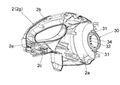
- Side view of the right housing 2g. The side view of the unit which combined the motor 6, the fan guide 10 and the fan cover 20.
- FIG. 14 is a cross-sectional view taken along the line XVI-XVI of FIG.
- FIG. The same front view.
- FIG. 19 is a cross-sectional view taken along the line XXII-XXII.
- Cleaner 1 is a cordless and portable non-cyclone vacuum cleaner. 1 and 4 define the front-back, up-down, and left-right directions of the cleaner 1 that are orthogonal to each other.
- the front-rear direction is a direction parallel to the rotation shaft 6a of the motor 6.
- the left-right direction is defined based on the case where the cleaner 1 is viewed from the front.
- the outer shell of the cleaner 1 is composed of a housing 2 and a dust case 3. Both the housing 2 and the dust case 3 are, for example, resin molded bodies.
- the dust case 3 is detachably connected and fixed to the front of the housing 2.
- An intake port (dust case intake port) 3a is provided at the front end of the dust case 3.
- An extension pipe or a flexible hose (not shown) can be attached to the intake port 3a.
- a filter member 40 is detachably mounted inside the dust case 3.
- the housing 2 has a left-right split structure. That is, the housing 2 is a housing 2 in which the left housing (first part) 2f and the right housing (second part) 2g, which are separate parts, are fixed and integrated with each other by screwing or the like.
- the housing 2 has an accommodating portion 2a, a handle portion 2b, and a battery pack mounting portion 2c.
- the accommodating portion 2a is a portion corresponding to the front portion of the housing 2.
- the accommodating portion 2a accommodates the motor 6, the dust collecting fan 9, the fan guide 10, and the fan cover 20.
- the handle portion 2b is a portion extending rearward from the upper end portion of the accommodating portion 2a. The operator grips the handle portion 2b and handles the cleaner 1.
- An operation panel (switch portion) 5 is provided on the upper surface of the handle portion 2b. Various switches provided on the operation panel 5 can start and stop the cleaner 1 and switch the air volume of the cleaner 1.
- the battery pack mounting portion 2c is a portion corresponding to the lower rear portion of the housing 2.
- a battery pack 4 that serves as a power source for the cleaner 1 is detachably mounted on the battery pack mounting portion 2c.
- Exhaust ports 2e are provided on both left and right sides of the rear end of the housing 2.
- the housing 2 has a flange portion 2i protruding inward at the front end portion.
- the flange portion 2i is a plate-shaped portion perpendicular to the front-rear direction.
- the flange portion 2i is provided so as to go around the extension line of the rotating shaft 6a of the motor 6.
- the entire rotation shaft 6a and its extension line are also referred to as a “central axis”.
- the inner edge of the flange portion 2i is the opening edge of the intake port (housing intake port) 2d.
- the intake port 2d is a circular through hole centered on the central axis and penetrating in the extending direction of the rotating shaft 6a.
- the intake port 2d is formed so as to straddle the left housing 2f and the right housing 2g.
- the intake port 2d communicates with the space inside the dust case 3.
- the front of the intake port 2d is covered with the filter member 40.
- the motor 6 is a well-known electric motor with a brush.
- the motor 6 is configured as a unit including a motor case and bearings.
- the motor 6 operates on the power supplied from the battery pack 4.
- the rear end portion of the motor 6 is supported by the housing 2 via an elastic body 7 for vibration isolation.
- a dust collecting fan 9 is attached to the rotating shaft 6a of the motor 6.
- the dust collecting fan 9 rotates integrally with the rotating shaft 6a around the rotating shaft 6a.
- the rotating shaft 6a is also the central shaft of the dust collecting fan 9.
- the dust collecting fan 9 is a centrifugal fan.
- the dust collecting fan 9 is housed in an internal space formed by the fan guide 10 and the fan cover 20.
- the outer diameters of the fan guide 10 and the fan cover 20 are larger than the outer diameter of the dust collecting fan 9.
- the outer diameter of the dust collecting fan 9 is larger than the outer diameter of the motor case.
- Both the fan guide 10 and the fan cover 20 are, for example, resin molded bodies.
- the fan guide 10 is fixed to the front surface of the motor 6 by screwing or the like.
- the fan cover 20 is fixed and integrated with the fan guide 10 by claw engagement or the like.
- the fan guide 10 is located behind the dust collecting fan 9.
- the fan guide 10 has a vent (not shown) for passing the air flow generated by the dust collecting fan 9.
- the fan cover 20 has a cylindrical shape centered on the rotation shaft 6a.
- the rear end of the fan cover 20 is open.
- the front end of the fan cover 20 is not open except for the intake port (fan cover intake port) 21. That is, the intake port 21 is provided on the front surface of the fan cover 20.
- the intake port 21 is a circular through hole centered on the central axis and penetrating in the extending direction of the rotating shaft 6a. As shown in FIG.
- the fan cover 20 has a grid portion 22 that crosses the intake port 21 vertically and horizontally. As shown in FIG. 12, the lattice portion 22 projects forward from the opening surface of the intake port 21. The lattice portion 22 has a function of preventing a finger or a large foreign substance from entering the inside of the fan cover 20 from the intake port 21.
- a part of the front surface of the fan cover 20 is an inclined surface 23. The inclined surface 23 is provided so as to surround the entire circumference of the intake port 21.
- the sealing member 30 seals (closes airtightly) between the housing 2 and the fan cover 20. Specifically, the seal member 30 comes into contact with the inside of the intake port 2d in the housing 2 and the outside of the intake port 21 in the fan cover 20, so that the housing 2 and the fan cover 20 are between the intake port 2d and the intake port 21. Seal the inside and outside of the car to prevent air from passing through.
- the seal member 30 also has an anti-vibration function.
- the seal member 30 is an elastic body such as rubber.
- the seal member 30 is formed in an annular shape centered on the central axis, and the intake port 2d and the intake port 21 communicate with each other through a hole provided in the center of the seal member 30 as a communication passage.
- the seal member 30 is arranged around the intake port 21.
- the outer diameter of the seal member 30 is smaller than the outer diameter of the fan cover 20.
- the outer diameter of the sealing member 30 is larger than the outer diameter of the elastic body 7.
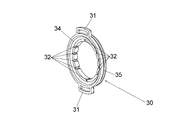
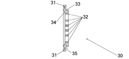
- the seal member 30 includes a first rotation regulating portion 31, a second rotation regulating portion 32, a first sealing portion 33, and a second sealing portion 34.
- the first rotation restricting portion 31 is a convex portion protruding outward from the outer peripheral surface of the seal member 30.
- the first rotation control unit 31 is provided at the upper part and the lower part of the seal member 30, respectively.
- the housing 2 has a detent portion 2h that sandwiches the first rotation restricting portion 31 from both the left and right sides. In the process of combining the left housing 2f and the right housing 2g, the first rotation restricting portion 31 is sandwiched by the detent portion 2h. The relative rotation of the seal member 30 with respect to the housing 2 is restricted by the engagement between the first rotation restricting portion 31 and the detent portion 2h.
- the second rotation restricting portion 32 is a recess, for example, a groove portion extending in the central axis direction formed on the inner peripheral surface (inner peripheral portion) of the seal member 30.
- a plurality of second rotation restricting units 32 are provided in the circumferential direction about the central axis.
- the second rotation restricting portion 32 is provided along the opening of the intake port 21 when viewed from the front. As shown in FIG. 4, the end portion of the grid portion 22 fits into each of the second rotation restricting portions 32.
- the relative rotation of the seal member 30 with respect to the fan cover 20 is restricted by the fitting (engagement) between the second rotation regulating portion 32 and the grid portion 22.
- the first seal portion 33 is a surface facing the front of the seal member 30.
- the first seal portion 33 comes into surface contact with the rear surface of the flange portion 2i over the entire circumference in the circumferential direction centered on the central axis.
- the seal member 30 receives a forward pressing force from the fan cover 20. By this pressing force, the first seal portion 33 is pressed against the rear surface of the flange portion 2i. As a result, the airtightness between the seal member 30 and the housing 2 is ensured.
- a groove portion (neck portion) 35 that goes around the central axis is provided on the outer peripheral surface of the seal member 30.
- the first seal portion 33 may include a groove portion 35.
- the fitting portion between the groove portion 35 and the flange portion 2i also contributes to ensuring the airtightness between the seal member 30 and the housing 2.
- the second seal portion 34 is a surface facing the rear of the seal member 30.
- the second seal portion 34 is an inclined surface inclined with respect to a surface perpendicular to the central axis direction.
- the second seal portion 34 extends rearward while expanding from the rear end of the inner peripheral surface on which the second rotation restricting portion 32 is formed.
- the second seal portion 34 comes into surface contact with the inclined surface 23 of the fan cover 20 over the entire circumference in the circumferential direction centered on the central axis.
- the inclined surface 23 is pressed against the second seal portion 34 by the forward pressing force applied from the fan cover 20 to the seal member 30. As a result, the airtightness between the seal member 30 and the fan cover 20 is ensured.
- the position of the second rotation restricting unit 32 in the radial direction around the central axis (hereinafter, simply referred to as “diameter direction”) is located on the central axis side of the first seal unit 33.
- the first seal portion 33 is provided within the arrangement range of the second rotation restricting portion 32 in the central axis direction.
- the first seal portion 33 may be provided outside the arrangement range of the second rotation restricting portion 32 in the central axis direction, but even in that case, it is preferable that the first seal portion 33 is provided within the arrangement range of the second seal portion 34 in the central axis direction. ..
- the positions of the first seal portion 33 and the second seal portion 34 are different from each other in the central axis direction.
- the first seal portion 33 is located on the front side of the second seal portion 34 in the central axis direction.
- the first seal portion 33 is formed inside the outer edge (outer edge substantially perpendicular to the radial direction) of the first rotation restricting portion 31 in the radial direction.
- the first seal portion 33 is formed so as to be located in the vicinity of the first rotation restricting portion 31 in the central axis direction.
- the second rotation restricting portion 32 and the first sealing portion 33 are arranged so that their positions in the central axis direction overlap.
- the dust collecting fan 9 When the operator operates the switch on the operation panel 5 to drive the motor 6, the dust collecting fan 9 is rotated by the driving force of the motor 6. The airflow generated by the dust collecting fan 9 is taken into the dust case 3 from the intake port 3a. The air flow passes through the filter member 40 and is taken into the fan cover 20 from the intake ports 2d and 21. The airflow is sucked into the inside of the dust collecting fan 9 and discharged to the outside, guided by the fan cover 20, and exits rearward from a vent of the fan guide 10 (not shown). The airflow is finally exhausted from the exhaust port 2e to the outside of the housing 2. Dust that has entered from the intake port 3a together with the air flow is collected by the filter member 40 and collects inside the dust case 3 and outside the filter member 40. The presence of the seal member 30 prevents airflow from circulating inside and outside the fan cover 20. As a result, the suction efficiency from the intake port 3a is enhanced.
- the seal member 30 has a smaller diameter than the fan cover 20. Therefore, the seal member 30 can be made smaller and lighter than a large seal member that covers up to the outer peripheral surface of the fan cover 20. Therefore, it is possible to suppress an increase in size, weight, and manufacturing cost of the entire product.
- the seal member 30 not only improves the suction force by the seal, but also functions as a vibration-proof member. Therefore, as compared with the case where the anti-vibration member is provided separately from the seal member, the number of parts can be reduced, and the suction force and the anti-vibration property can be improved with a simple structure. Further, since the fan motor unit including the motor 6, the dust collecting fan 9, the fan guide 10 and the fan cover 20 is supported by the housing 2 only by the elastic body 7 made of an elastic body such as rubber and the seal member 30, the fan motor The vibration generated in the unit is suppressed from being transmitted to the housing 2.
- the first seal portion 33 is pressed against the rear surface of the flange portion 2i, and the inclined surface 23 is pressed against the second seal portion 34 by the forward pressing force applied from the fan cover 20 to the seal member 30. That is, the seal member 30 is sandwiched between the fan cover 20 and the flange portion 2i from the front-rear direction.
- the flange portion 2i is fitted into the groove portion 35, and the sealing member 30 is sandwiched between the left housing 2f and the right housing 2g from the left-right direction.
- the second rotation regulating unit 32 regulates the relative rotation of the seal member 30 with respect to the fan cover 20 by engaging with the grid unit 22.
- the grid portion 22 prevents the entry of fingers and foreign matter from the intake port 21. Therefore, in order to regulate the relative rotation of the seal member 30 with respect to the fan cover 20, it is not necessary to separately add a configuration for preventing rotation on the fan cover 20 side. Therefore, the complexity of the configuration can be suppressed.
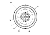
- Embodiment 2 The second embodiment of the present invention will be described with reference to FIGS. 14 to 18. This embodiment also relates to a cleaner. Hereinafter, the differences from the first embodiment will be mainly described, and the common points with the first embodiment will be omitted as appropriate.
- the seal member 30A and the fan cover 20A replace the seal member 30 and the fan cover 20 of the first embodiment.
- the seal member 30A eliminates the second rotation regulation unit 32 of the seal member 30 and provides a second rotation regulation unit 32A instead.
- the second rotation restricting portion 32A is a hole provided on the rear surface of the seal member 30A, preferably a non-through hole.
- the second rotation restricting unit 32A is provided at intervals of 90 ° in the circumferential direction about the central axis.
- the fan cover 20A has the same number of convex portions (locking portions) 24 as the second rotation restricting portion 32A around the intake port 21. The position of the convex portion 24 in the circumferential direction about the central axis coincides with the second rotation restricting portion 32A.
- the convex portion 24 fits into the second rotation restricting portion 32A.
- the relative rotation of the seal member 30A with respect to the fan cover 20A is restricted by the fitting (engagement) between the convex portion 24 and the second rotation restricting portion 32A.
- the rib 22 does not project forward from the opening surface of the intake port 21, but may project as in the case of the first embodiment.
- the convex portion 24 is required on the fan cover 20 side as a configuration for preventing rotation, the same effect as that of the first embodiment can be obtained in other respects.
- the third embodiment of the present invention will be described with reference to FIGS. 19 to 22.
- This embodiment also relates to a cleaner.
- the differences from the first embodiment will be mainly described, and the common points with the first embodiment will be omitted as appropriate.
- the seal member 30B replaces the seal member 30 of the first embodiment.
- the seal member 30B has a hole (cavity) 36 on the rear surface.
- the hole 36 is preferably a non-through hole.
- a large number (16 in the illustrated example) of holes 36 are preferably provided at equal intervals in the circumferential direction about the central axis.
- the hole portion 36 is located between the first rotation restricting portion 31 and the second rotation regulating portion 32 in the radial direction.
- the hole portion 36 has a function of increasing the flexibility of the seal member 30B, that is, a function of facilitating elastic deformation of the seal member 30B. According to the present embodiment, the flexibility of the seal member 30B is increased, so that the anti-vibration effect of the seal member 30B is enhanced.
- the cleaner of the present invention may be a cyclone type or a corded type that operates with power supplied from an external AC power source.
- the motor may be a brushless motor.
Landscapes
- Engineering & Computer Science (AREA)
- Mechanical Engineering (AREA)
- General Engineering & Computer Science (AREA)
- Structures Of Non-Positive Displacement Pumps (AREA)
- Electric Suction Cleaners (AREA)
Priority Applications (2)
| Application Number | Priority Date | Filing Date | Title |
|---|---|---|---|
| CN202080082841.5A CN114727731B (zh) | 2019-11-27 | 2020-10-30 | 清洁器 |
| JP2021561244A JP7315025B2 (ja) | 2019-11-27 | 2020-10-30 | クリーナ |
Applications Claiming Priority (2)
| Application Number | Priority Date | Filing Date | Title |
|---|---|---|---|
| JP2019-214789 | 2019-11-27 | ||
| JP2019214789 | 2019-11-27 |
Publications (1)
| Publication Number | Publication Date |
|---|---|
| WO2021106493A1 true WO2021106493A1 (ja) | 2021-06-03 |
Family
ID=76129527
Family Applications (1)
| Application Number | Title | Priority Date | Filing Date |
|---|---|---|---|
| PCT/JP2020/040879 Ceased WO2021106493A1 (ja) | 2019-11-27 | 2020-10-30 | クリーナ |
Country Status (3)
| Country | Link |
|---|---|
| JP (1) | JP7315025B2 (https=) |
| CN (1) | CN114727731B (https=) |
| WO (1) | WO2021106493A1 (https=) |
Cited By (3)
| Publication number | Priority date | Publication date | Assignee | Title |
|---|---|---|---|---|
| JP2022100046A (ja) * | 2020-12-23 | 2022-07-05 | 株式会社マキタ | 送風機 |
| US11795967B2 (en) | 2020-12-23 | 2023-10-24 | Makita Corporation | Blower |
| US12421977B2 (en) | 2020-12-23 | 2025-09-23 | Makita Corporation | Blower |
Citations (5)
| Publication number | Priority date | Publication date | Assignee | Title |
|---|---|---|---|---|
| JPH044690Y2 (https=) * | 1985-02-27 | 1992-02-12 | ||
| JPH04272733A (ja) * | 1991-02-28 | 1992-09-29 | Matsushita Electric Ind Co Ltd | 電動送風機の防振装置 |
| WO2014162773A1 (ja) * | 2013-04-01 | 2014-10-09 | 株式会社 マキタ | クリーナ |
| US20150184673A1 (en) * | 2014-01-02 | 2015-07-02 | Samsung Electronics Co., Ltd. | Fan motor assembly and vacuum cleaner having the same |
| JP2018068726A (ja) * | 2016-10-31 | 2018-05-10 | 日立工機株式会社 | 集塵装置 |
Family Cites Families (4)
| Publication number | Priority date | Publication date | Assignee | Title |
|---|---|---|---|---|
| JP5598222B2 (ja) * | 2010-09-30 | 2014-10-01 | 株式会社アドヴィックス | 軸シール装置とそれを用いたポンプ装置及びブレーキ液圧制御装置 |
| JP2013141514A (ja) * | 2012-01-11 | 2013-07-22 | Hitachi Appliances Inc | 電気掃除機 |
| JP2013204784A (ja) * | 2012-03-29 | 2013-10-07 | Nippon Densan Corp | 軸受装置および送風ファン |
| CN110268604B (zh) * | 2017-02-14 | 2021-05-28 | 日本电产三协株式会社 | 电动机及泵装置 |
-
2020
- 2020-10-30 JP JP2021561244A patent/JP7315025B2/ja active Active
- 2020-10-30 WO PCT/JP2020/040879 patent/WO2021106493A1/ja not_active Ceased
- 2020-10-30 CN CN202080082841.5A patent/CN114727731B/zh active Active
Patent Citations (5)
| Publication number | Priority date | Publication date | Assignee | Title |
|---|---|---|---|---|
| JPH044690Y2 (https=) * | 1985-02-27 | 1992-02-12 | ||
| JPH04272733A (ja) * | 1991-02-28 | 1992-09-29 | Matsushita Electric Ind Co Ltd | 電動送風機の防振装置 |
| WO2014162773A1 (ja) * | 2013-04-01 | 2014-10-09 | 株式会社 マキタ | クリーナ |
| US20150184673A1 (en) * | 2014-01-02 | 2015-07-02 | Samsung Electronics Co., Ltd. | Fan motor assembly and vacuum cleaner having the same |
| JP2018068726A (ja) * | 2016-10-31 | 2018-05-10 | 日立工機株式会社 | 集塵装置 |
Cited By (5)
| Publication number | Priority date | Publication date | Assignee | Title |
|---|---|---|---|---|
| JP2022100046A (ja) * | 2020-12-23 | 2022-07-05 | 株式会社マキタ | 送風機 |
| US11795967B2 (en) | 2020-12-23 | 2023-10-24 | Makita Corporation | Blower |
| US12055158B2 (en) | 2020-12-23 | 2024-08-06 | Makita Corporation | Blower |
| US12421977B2 (en) | 2020-12-23 | 2025-09-23 | Makita Corporation | Blower |
| US12473927B2 (en) | 2020-12-23 | 2025-11-18 | Makita Corporation | Blower |
Also Published As
| Publication number | Publication date |
|---|---|
| JPWO2021106493A1 (https=) | 2021-06-03 |
| CN114727731A (zh) | 2022-07-08 |
| CN114727731B (zh) | 2023-09-26 |
| JP7315025B2 (ja) | 2023-07-26 |
Similar Documents
| Publication | Publication Date | Title |
|---|---|---|
| WO2021106493A1 (ja) | クリーナ | |
| JP7762603B2 (ja) | 作業機 | |
| KR101259678B1 (ko) | 전기 진공 청소기 | |
| WO2020121847A1 (ja) | クリーナ | |
| JP2009131329A (ja) | 電気掃除機 | |
| KR20010014670A (ko) | 전동송풍기 및 그것을 사용한 전기청소기 | |
| EP3450769A1 (en) | Motor module and vacuum cleaner | |
| US20190069741A1 (en) | Motor module and vacuum cleaner | |
| JP2023132055A (ja) | 作業機 | |
| US11744419B2 (en) | Cleaner | |
| CN106715922B (zh) | 离心式鼓风机及具备该离心式鼓风机的汽车 | |
| JP2008212500A (ja) | 電気掃除機 | |
| JP2009207555A (ja) | 電気掃除機 | |
| JP2001003898A (ja) | 電動送風機及びそれを用いた電気掃除機 | |
| JP2020018577A (ja) | クリーナ | |
| JP2020092909A (ja) | クリーナ | |
| WO2021117509A1 (ja) | クリーナ | |
| US20260069095A1 (en) | Cleaner | |
| JP5632884B2 (ja) | 動力工具 | |
| JP7762601B2 (ja) | 作業機 | |
| JP5368166B2 (ja) | 電気掃除機 | |
| JP2022045844A (ja) | フィルタ装置及び作業機 | |
| JP7526488B2 (ja) | 電気掃除機の吸込口体、及び電気掃除機 | |
| JP2025019960A (ja) | 作業機 | |
| JP2025031532A (ja) | 作業機 |
Legal Events
| Date | Code | Title | Description |
|---|---|---|---|
| 121 | Ep: the epo has been informed by wipo that ep was designated in this application |
Ref document number: 20894559 Country of ref document: EP Kind code of ref document: A1 |
|
| ENP | Entry into the national phase |
Ref document number: 2021561244 Country of ref document: JP Kind code of ref document: A |
|
| NENP | Non-entry into the national phase |
Ref country code: DE |
|
| 122 | Ep: pct application non-entry in european phase |
Ref document number: 20894559 Country of ref document: EP Kind code of ref document: A1 |