WO2021106200A1 - 吸引装置、情報処理方法、及びプログラム - Google Patents
吸引装置、情報処理方法、及びプログラム Download PDFInfo
- Publication number
- WO2021106200A1 WO2021106200A1 PCT/JP2019/046816 JP2019046816W WO2021106200A1 WO 2021106200 A1 WO2021106200 A1 WO 2021106200A1 JP 2019046816 W JP2019046816 W JP 2019046816W WO 2021106200 A1 WO2021106200 A1 WO 2021106200A1
- Authority
- WO
- WIPO (PCT)
- Prior art keywords
- suction device
- information
- user
- unit
- suction
- Prior art date
- Legal status (The legal status is an assumption and is not a legal conclusion. Google has not performed a legal analysis and makes no representation as to the accuracy of the status listed.)
- Ceased
Links
Images


Classifications
-
- A—HUMAN NECESSITIES
- A24—TOBACCO; CIGARS; CIGARETTES; SIMULATED SMOKING DEVICES; SMOKERS' REQUISITES
- A24F—SMOKERS' REQUISITES; MATCH BOXES; SIMULATED SMOKING DEVICES
- A24F40/00—Electrically operated smoking devices; Component parts thereof; Manufacture thereof; Maintenance or testing thereof; Charging means specially adapted therefor
- A24F40/65—Devices with integrated communication means, e.g. wireless communication means
-
- A—HUMAN NECESSITIES
- A24—TOBACCO; CIGARS; CIGARETTES; SIMULATED SMOKING DEVICES; SMOKERS' REQUISITES
- A24F—SMOKERS' REQUISITES; MATCH BOXES; SIMULATED SMOKING DEVICES
- A24F40/00—Electrically operated smoking devices; Component parts thereof; Manufacture thereof; Maintenance or testing thereof; Charging means specially adapted therefor
- A24F40/50—Control or monitoring
- A24F40/53—Monitoring, e.g. fault detection
-
- A—HUMAN NECESSITIES
- A24—TOBACCO; CIGARS; CIGARETTES; SIMULATED SMOKING DEVICES; SMOKERS' REQUISITES
- A24F—SMOKERS' REQUISITES; MATCH BOXES; SIMULATED SMOKING DEVICES
- A24F40/00—Electrically operated smoking devices; Component parts thereof; Manufacture thereof; Maintenance or testing thereof; Charging means specially adapted therefor
- A24F40/60—Devices with integrated user interfaces
-
- A—HUMAN NECESSITIES
- A24—TOBACCO; CIGARS; CIGARETTES; SIMULATED SMOKING DEVICES; SMOKERS' REQUISITES
- A24F—SMOKERS' REQUISITES; MATCH BOXES; SIMULATED SMOKING DEVICES
- A24F40/00—Electrically operated smoking devices; Component parts thereof; Manufacture thereof; Maintenance or testing thereof; Charging means specially adapted therefor
- A24F40/10—Devices using liquid inhalable precursors
-
- A—HUMAN NECESSITIES
- A24—TOBACCO; CIGARS; CIGARETTES; SIMULATED SMOKING DEVICES; SMOKERS' REQUISITES
- A24F—SMOKERS' REQUISITES; MATCH BOXES; SIMULATED SMOKING DEVICES
- A24F40/00—Electrically operated smoking devices; Component parts thereof; Manufacture thereof; Maintenance or testing thereof; Charging means specially adapted therefor
- A24F40/20—Devices using solid inhalable precursors
-
- A—HUMAN NECESSITIES
- A24—TOBACCO; CIGARS; CIGARETTES; SIMULATED SMOKING DEVICES; SMOKERS' REQUISITES
- A24F—SMOKERS' REQUISITES; MATCH BOXES; SIMULATED SMOKING DEVICES
- A24F40/00—Electrically operated smoking devices; Component parts thereof; Manufacture thereof; Maintenance or testing thereof; Charging means specially adapted therefor
- A24F40/30—Devices using two or more structurally separated inhalable precursors, e.g. using two liquid precursors in two cartridges
-
- A—HUMAN NECESSITIES
- A24—TOBACCO; CIGARS; CIGARETTES; SIMULATED SMOKING DEVICES; SMOKERS' REQUISITES
- A24F—SMOKERS' REQUISITES; MATCH BOXES; SIMULATED SMOKING DEVICES
- A24F40/00—Electrically operated smoking devices; Component parts thereof; Manufacture thereof; Maintenance or testing thereof; Charging means specially adapted therefor
- A24F40/85—Maintenance, e.g. cleaning
Definitions
- the present invention relates to a suction device, an information processing method, and a program.
- the suction device uses a base material containing an aerosol source for producing an aerosol, a flavor source for imparting a flavor component to the produced aerosol, and the like to generate an aerosol to which the flavor component is added.
- the user can taste the flavor by sucking the aerosol to which the flavor component is added (hereinafter, also referred to as puff) generated by the suction device.
- Patent Document 1 displays information recommending that the suction device be cleaned according to the number of times the suction device is used, and if the suction device is not cleaned, the suction device cannot be used. The technology to make it is disclosed.
- the suction device may be equipped with only a simple output device such as a light emitting device as a device for notifying the user of information.
- a simple output device such as a light emitting device
- the limitation on the expressiveness of information can be a bottleneck for improving usability.
- an object of the present invention is to provide a mechanism capable of improving the usability of the suction device.
- a suction device a suction device, a wireless communication unit that wirelessly transmits and receives information, a notification unit that notifies the user of information, and information notified to the user.
- the wireless communication unit is controlled so that the notification information is transmitted to the other device when the suction device and the other device are wirelessly connected, and the suction device and the other device are wirelessly connected.
- a suction device including a control unit that controls the notification unit to notify the user when the notification is not performed is provided.
- the control unit may acquire information about the suction device and determine whether or not to notify the user of the notification information based on the acquired information about the suction device.
- the control unit does not have to notify the notification information by the notification unit when the suction device and the other device are wirelessly connected.
- the timing at which the control unit determines whether or not to notify the user of the notification information may be later than the timing at which the suction device and another device are determined whether or not they are wirelessly connected. ..
- the timing at which the control unit determines whether or not to notify the user of the notification information may be earlier than the timing at which the suction device and another device are determined whether or not they are wirelessly connected. ..
- the notification information may include information indicating the need to clean the suction device.
- the information about the suction device includes the number of preheatings performed by the suction device to allow the user to perform suction using the suction device, and the control unit has a first number of preheatings.
- the threshold value of it may be determined that the first information is notified to the user as information indicating the necessity of cleaning the suction device.
- the number of preheatings may be initialized when a predetermined user operation is performed.
- the control unit may count the number of times of the preheating when it is determined that the preheating is performed on the base material that contributes to the generation of the substance sucked by the user when heated. ..
- the suction device may further include a storage unit, and the storage unit may store the number of times of the preheating.
- the control unit When the number of preheatings reaches a second threshold value lower than the first threshold value, the control unit notifies the user of the second information as information indicating the necessity of cleaning the suction device. Then, it may be determined.
- the information about the suction device is that when the suction device performs preheating to enable suction performed by the user using the suction device, the temperature of the object to be heated or the temperature of the heating unit that performs the preheating is determined.
- the control unit includes the time required to reach the predetermined temperature. It may be determined that the user is notified of the first information as information indicating the necessity of cleaning the suction device.
- the control unit may set the third threshold value based on the environmental temperature which is the ambient temperature of the suction device.
- the control unit sets the suction device. It may be determined that the user is notified of the second information as the information indicating the necessity of cleaning.
- the information about the suction device is that when the suction device performs preheating to enable suction performed by the user using the suction device, the temperature of the object to be heated or the temperature of the heating unit that performs the preheating is determined.
- the control unit includes the power required to reach a predetermined temperature, and the control unit receives the temperature of the heating target or the power required to reach the predetermined temperature when the temperature of the heating unit reaches the fifth threshold value. It may be determined that the user is notified of the first information as information indicating the necessity of cleaning the suction device.
- the control unit may set the fifth threshold value based on the environmental temperature which is the ambient temperature of the suction device.
- the control unit uses the suction device when the temperature of the heating target or the electric power required for the temperature of the heating unit to reach the predetermined temperature reaches a sixth threshold value lower than the fifth threshold value. It may be determined that the user is notified of the second information as the information indicating the necessity of cleaning.
- the notification information may include information indicating a method of cleaning the suction device.
- the information indicating the necessity of cleaning the suction device may include information regarding the timing of cleaning the suction device.
- the notification information is a substrate that contributes to the production of a substance that is sucked by the user when the contents are consumed, and is used by the suction device to generate a substance that is sucked by the user. It may contain information indicating the need to replace the substrate.
- the information about the suction device includes the number of suctions performed by the user using the suction device, and the control unit needs to replace the base material when the number of suctions reaches the seventh threshold value. It may be determined that the third information is notified to the user as the information indicating the sex.
- the number of suctions may be initialized when the base material is replaced.
- the suction device may further include a storage unit, and the storage unit may store the number of times of suction.
- control unit When the control unit reaches the eighth threshold value lower than the seventh threshold value, the control unit notifies the user of the fourth information as information indicating the necessity of replacing the base material. You may judge.
- the information about the suction device includes the rate of change in the resistance value of the heating unit that heats the base material, and the control unit needs to replace the base material based on the rate of change in the resistance value of the heating unit. It may be determined whether or not to notify the information to be shown.
- the information indicating the necessity of exchanging the base material may include information regarding the timing of exchanging the base material.
- the notification information may include information indicating that the suction device is in an abnormal state.
- the notification unit may include at least one of a display device, a light emitting device, a vibration device, and a sound output device.
- the notification information which is the information processing method executed by the suction device and is the information to be notified to the user is different from the suction device.
- the information is transmitted wirelessly to the other device, and when the suction device and the other device are not wirelessly connected, the suction device notifies the user.
- Information processing methods are provided.
- the computer that controls the suction device is a wireless communication unit that wirelessly transmits and receives information, a notification unit that notifies the user of the information, and a user.
- the wireless communication unit is controlled so that the notification information, which is the information notified to the user, is transmitted to the other device when the suction device and the other device are wirelessly connected, and the suction device and the other device are transmitted.
- a program for functioning as a control unit that controls the notification unit to notify the user when the device is not wirelessly connected is provided.
- a mechanism capable of improving the usability of the suction device is provided.
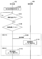
- FIG. 1 It is a schematic diagram which shows typically the tenth structural example of a suction device. It is a block diagram which shows an example of the structure of the system which concerns on one Embodiment of this invention. It is a sequence diagram which shows an example of the flow of the information notification processing executed by the system which concerns on this embodiment.
- the suction device is a device that produces a substance that is sucked by the user.
- the substance produced by the suction device will be described as being an aerosol.
- the substance produced by the suction device may be a gas.
- the user sucking the substance produced by the suction device is also simply referred to as "suction" or "puff".
- a plurality of elements having a corresponding functional configuration are given a reference code including the same number to clearly indicate the correspondence, and the alphabet corresponding to the configuration example is added after the number. May be added to distinguish each element.
- each of the suction devices according to the plurality of configuration examples is referred to as a suction device 100A according to the first configuration example, a suction device 100B according to the second configuration example, and a suction device 100D according to the third configuration example. Then, each is distinguished while clearly indicating the correspondence.
- the reference code including the same number may be attached.
- the suction device 100A according to the first configuration example when it is not necessary to distinguish the suction device 100A according to the first configuration example, the suction device 100B according to the second configuration example, and the suction device 100D according to the third configuration example, these are simply sucked. Also referred to as device 100.
- the base material integrated suction device is a suction device in which a base material including an aerosol source is integrated with the suction device.
- the first to third configuration examples described below are configuration examples of a base material-integrated suction device.
- the suction device according to this configuration example produces an aerosol by heating an aerosol source as a liquid.
- the suction device according to this configuration example consists of two parts, a power supply unit and a cartridge.
- this configuration example will be described with reference to FIG.
- FIG. 1 is a schematic view schematically showing a first configuration example of the suction device.
- the suction device 100A according to this configuration example includes a power supply unit 110A and a cartridge 120A.
- the power supply unit 110A and the cartridge 120A are configured to be detachable from each other. The suction by the user is performed with the cartridge 120A attached to the power supply unit 110A.
- the power supply unit 110A includes a power supply unit 111A, a sensor unit 112A, a notification unit 113A, a storage unit 114A, a communication unit 115A, and a control unit 116A.
- the cartridge 120A includes a heating unit 121A, a liquid induction unit 122A, a liquid storage unit 123A, and a mouthpiece 124A.
- An air flow path 180A is formed in the cartridge 120A.
- each component will be described in order.
- the power supply unit 111A stores electric power. Then, the power supply unit 111A supplies electric power to each component of the suction device 100A.
- the power supply unit 111A may be composed of, for example, a rechargeable battery such as a lithium ion secondary battery.
- the power supply unit 111A may be charged by being connected to an external power supply by a USB (Universal Serial Bus) cable or the like. Further, the power supply unit 111A may be charged in a state of being disconnected from the device on the power transmission side by the wireless power transmission technology. Alternatively, only the power supply unit 111A may be removed from the suction device 100A, or may be replaced with a new power supply unit 111A.
- the sensor unit 112A detects various information related to the suction device 100A. Then, the sensor unit 112A outputs the detected information to the control unit 116A.
- the sensor unit 112A is composed of a pressure sensor such as a microphone capacitor. Then, when the sensor unit 112A detects the negative pressure accompanying the suction by the user, the sensor unit 112A outputs information indicating that the suction by the user has been performed to the control unit 116A.
- the sensor unit 112A is composed of an input device such as a button or a switch that receives input of information from the user. In particular, the sensor unit 112A may include a button instructing the start / stop of aerosol production. Then, the sensor unit 112A outputs the information input by the user to the control unit 116A.
- the notification unit 113A notifies the user of the information.
- the notification unit 113A is composed of a light emitting device such as an LED (Light Emitting Diode). In that case, the notification unit 113A emits light in different light emission patterns when the state of the power supply unit 111A requires charging, when the power supply unit 111A is charging, or when an abnormality occurs in the suction device 100A. ..
- the light emission pattern here is a concept including color, lighting / extinguishing timing, and the like.
- the notification unit 113A may be composed of a display device for displaying an image, a sound output device for outputting sound, a vibrating vibration device, or the like, together with or in place of the light emitting device.
- the storage unit 114A stores various information for the operation of the suction device 100A.
- the storage unit 114A is composed of a non-volatile storage medium such as a flash memory.
- An example of the information stored in the storage unit 114A is information related to the OS (Operating System) of the suction device 100A, such as the control contents of various components by the control unit 116A.
- Another example of the information stored in the storage unit 114A is information related to suction by the user, such as the number of suctions, the suction time, and the cumulative suction time.
- the communication unit 115A is a communication interface for transmitting and receiving information between the suction device 100A and another device.
- the communication unit 115A performs communication conforming to any wired or wireless communication standard.
- a communication standard for example, wireless LAN (Local Area Network), wired LAN, Wi-Fi (registered trademark), Bluetooth (registered trademark), or the like can be adopted.
- the communication unit 115A transmits the information on the suction by the user to the smartphone in order to display the information on the suction by the user on the smartphone.
- the communication unit 115A receives new OS information from the server in order to update the OS information stored in the storage unit 114A.
- the control unit 116A functions as an arithmetic processing unit and a control device, and controls the overall operation in the suction device 100A according to various programs.
- the control unit 116A is realized by, for example, an electronic circuit such as a CPU (Central Processing Unit) and a microprocessor.
- the control unit 116A may include a ROM (Read Only Memory) that stores a program to be used, calculation parameters, and the like, and a RAM (Random Access Memory) that temporarily stores parameters and the like that change as appropriate.
- the suction device 100A executes various processes based on the control by the control unit 116A.
- Information transmission / reception is an example of processing controlled by the control unit 116A.
- Other processes executed by the suction device 100A, such as input of information to each component and processing based on the information output from each component, are also controlled by the control unit 116A.
- the liquid storage unit 123A stores the aerosol source.
- the aerosol source is atomized by heating to produce an aerosol. Aerosol sources are, for example, polyhydric alcohols such as glycerin and propylene glycol, and liquids such as water.
- the aerosol source may further comprise a tobacco ingredient or an extract derived from the tobacco ingredient that releases the flavor component upon heating. If the aspirator 100A is a medical inhaler such as a nebulizer, the aerosol source may include a drug for the patient to inhale.
- the liquid induction unit 122A guides and holds the aerosol source, which is the liquid stored in the liquid storage unit 123A, from the liquid storage unit 123A.
- the liquid induction portion 122A is a wick formed by twisting, for example, a fiber material such as glass fiber or a porous material such as a porous ceramic.
- the liquid induction unit 122A communicates with the liquid storage unit 123A. Therefore, the aerosol source stored in the liquid storage unit 123A spreads throughout the liquid induction unit 122A due to the capillary effect of the wick.
- the heating unit 121A heats the aerosol source to atomize the aerosol source and generate an aerosol.
- the heating unit 121A is made of an arbitrary material such as metal or polyimide in an arbitrary shape such as a coil shape, a film shape or a blade shape.
- the heating unit 121A is arranged close to the liquid induction unit 122A.
- the heating unit 121A is composed of a metal coil and is wound around the liquid induction unit 122A. Therefore, when the heating unit 121A generates heat, the aerosol source held by the liquid induction unit 122A is heated and atomized to generate an aerosol.
- the heating unit 121A generates heat when power is supplied from the power supply unit 111A.
- a power may be supplied to generate an aerosol during a period in which the sensor unit 112A detects that suction has been performed by the user.
- a predetermined user input for example, pressing a button instructing the start / stop of aerosol generation
- power is supplied and the aerosol is generated. Good.
- the power supply may be stopped.
- the air flow path 180A is a flow path of air sucked by the user.
- the air flow path 180A has a tubular structure having an air inflow hole 181A which is an inlet of air into the air flow path 180A and an air outflow hole 182A which is an outlet of air from the air flow path 180A at both ends. With suction by the user, air flows into the air flow path 180A from the air inflow hole 181A, and air flows out from the air outflow hole 182A to the outside of the air flow path 180A.
- the air inflow hole 181A may be a gap formed between the power supply unit 110A and the cartridge 120A with the cartridge 120A attached to the power supply unit 110A.
- the air outflow hole 182A is arranged in the mouthpiece 124A.
- a liquid guiding unit 122A is arranged in the middle of the air flow path 180A.
- the aerosol generated by the heating unit 121A is mixed with the air flowing in from the air inflow hole 181A. Then, along with the suction by the user, the mixed fluid of the aerosol and the air is transported to the air outflow hole 182A as shown by the arrow 190A.
- the mouthpiece 124A is a member that can be held by the user during suction.
- An air outflow hole 182A of the air flow path 180A is arranged in the mouthpiece 124A.
- the suction device according to this configuration example produces an aerosol by heating an aerosol source as a liquid.
- the suction device according to this configuration example includes three parts, a power supply unit, a cartridge, and a flavoring cartridge.
- this configuration example will be described with reference to FIG.
- FIG. 2 is a schematic view schematically showing a second configuration example of the suction device.
- the suction device 100B according to this configuration example includes a power supply unit 110B, a cartridge 120B, and a flavoring cartridge 130.
- the power supply unit 110B and the cartridge 120B are configured to be detachable from each other.
- the cartridge 120B and the flavor-imparting cartridge 130 are configured to be detachable from each other.
- the suction by the user is performed with the cartridge 120B, the flavoring cartridge 130, and the power supply unit 110B attached to each other.
- the power supply unit 110B includes a power supply unit 111B, a sensor unit 112B, a notification unit 113B, a storage unit 114B, a communication unit 115B, and a control unit 116B.
- the cartridge 120B includes a heating unit 121B, a liquid induction unit 122B, and a liquid storage unit 123B.
- the flavoring cartridge 130 includes a flavor source 131 and a mouthpiece 124B.
- An air flow path 180B is formed in the cartridge 120B and the flavoring cartridge 130.
- Each component of the power supply unit 110B is substantially the same as the corresponding component included in the suction device 100A according to the first configuration example.
- Each of the heating unit 121B, the liquid guiding unit 122B, the liquid storage unit 123B, and the mouthpiece 124B are substantially the same as the corresponding components included in the suction device 100A according to the first configuration example.
- the flavor source 131 is a component for imparting a flavor component to the aerosol.
- the flavor source 131 may be derived from tobacco, such as a processed product obtained by molding chopped tobacco or a tobacco raw material into granules, sheets, or powder.
- the flavor source 131 may include those derived from non-tobacco, which are made from plants other than tobacco (for example, mint and herbs).
- the flavor source 131 may contain a perfume component such as menthol.
- the flavor source 131 may be arranged inside a container such as a capsule.
- the air flow path 180B has the same configuration as the air flow path 180A according to the first configuration example. However, in the middle of the air flow path 180B, in addition to the liquid guiding portion 122B, the flavor source 131 is arranged on the downstream side (the side close to the air outflow hole 182B) of the liquid guiding portion 122B.
- the aerosol generated by the heating unit 121B is mixed with the air flowing in from the air inflow hole 181B. Then, with suction by the user, the mixed fluid of the aerosol and the air is transported to the air outflow hole 182B through the flavor source 131 as shown by the arrow 190B. Then, when the mixed fluid of the aerosol and the air passes through the flavor source 131, the flavor component contained in the flavor source 131 is imparted to the aerosol.
- FIG. 3 is a schematic view schematically showing a third configuration example of the suction device.
- the suction device 100D according to this configuration example includes a power supply unit 110D and a cartridge 120D.
- the power supply unit 110D and the cartridge 120D are configured to be detachable from each other. The suction by the user is performed with the cartridge 120D attached to the power supply unit 110D.
- the power supply unit 110D includes a power supply unit 111D, a sensor unit 112D, a notification unit 113D, a storage unit 114D, a communication unit 115D, and a control unit 116D.
- the cartridge 120D includes a heating unit 121D, a liquid induction unit 122D, a liquid storage unit 123D, a vibration unit 127, and a mouthpiece 124D. Further, an air flow path 180D is formed in the cartridge 120D.
- each component will be described in order.
- Each component of the power supply unit 110D is substantially the same as the corresponding component included in the suction device 100A according to the first configuration example.
- the liquid storage unit 123D and the mouthpiece 124D are also substantially the same as the corresponding components included in the suction device 100A according to the first configuration example.
- the liquid induction unit 122D guides the aerosol source, which is the liquid stored in the liquid storage unit 123D, from the liquid storage unit 123D to the vibration unit 127 and holds it.
- An example of the liquid induction portion 122D is a wick formed by twisting a fiber material such as glass fiber or a porous material such as a porous ceramic.
- Another example of the liquid guiding unit 122D is a plate capable of absorbing an aerosol source that is a liquid and guiding it to the vibrating unit 127.
- the liquid induction unit 122D communicates with the liquid storage unit 123D. Therefore, the aerosol source stored in the liquid storage unit 123D is guided to the surface of the vibrating unit 127 by the liquid induction unit 122D as shown by the arrow 191.
- the vibrating unit 127 atomizes the aerosol source to generate an aerosol by applying vibration to the aerosol source.
- the vibrating unit 127 is composed of a plate-shaped member containing piezoelectric ceramics that functions as an ultrasonic vibrator. Then, when the vibrating unit 127 vibrates, the aerosol source guided to the surface of the vibrating unit 127 by the liquid guiding unit 122D is atomized by the ultrasonic waves generated by the vibration by the vibrating unit 127, and the aerosol is generated.
- the vibrating unit 127 vibrates when power is supplied from the power supply unit 111D.
- a power may be supplied to generate an aerosol during a period in which the sensor unit 112D detects that suction has been performed by the user.
- the sensor unit 112D when the sensor unit 112D detects that a predetermined user input has been performed, power may be supplied to generate an aerosol. After that, when the sensor unit 112D detects that a predetermined user input has been performed, the power supply may be stopped.
- the air flow path 180D has the same configuration as the air flow path 180A according to the first configuration example. However, the liquid guiding portion 122D is arranged in the middle of the air flow path 180D.
- the aerosol generated by the vibrating unit 127 is mixed with the air flowing in from the air inflow hole 181D. Then, along with the suction by the user, the mixed fluid of the aerosol and the air is transported to the air outflow hole 182D as shown by the arrow 190D.
- the flavoring cartridge 130 may be arranged on the downstream side of the cartridge 120D as in the suction device 100B according to the second configuration example.
- the suction device 100D according to this configuration example may be composed of three parts, a power supply unit 110D, a cartridge 120D, and a flavoring cartridge 130.
- the base material external suction device is a suction device to which a base material including an aerosol source is externally attached.
- the fourth to seventh configuration examples described below are configuration examples of the base material external type suction device.
- FIG. 4 is a schematic view schematically showing a fourth configuration example of the suction device.
- the suction device 100E according to this configuration example includes a power supply unit 111E, a sensor unit 112E, a notification unit 113E, a storage unit 114E, a communication unit 115E, a control unit 116E, a heating unit 121E, and a holding unit 140E.
- the user sucks the stick-type base material 150E while the stick-type base material 150E is held by the holding portion 140E.
- each component will be described in order.
- Each of the power supply unit 111E, the sensor unit 112E, the storage unit 114E, the communication unit 115E, and the control unit 116E is substantially the same as the corresponding components included in the suction device 100A according to the first configuration example.
- the holding portion 140E has an internal space 141E, and holds the stick-type base material 150E while accommodating a part of the stick-type base material 150E in the internal space 141E.
- the holding portion 140E has an opening 142E that communicates the internal space 141E to the outside, and holds the stick-type base material 150E inserted into the internal space 141E through the opening 142E.
- the holding portion 140E is a tubular body having an opening 142E and a bottom portion 143E as a bottom surface, and defines a columnar internal space 141E.
- the holding portion 140E is configured so that the inner diameter is smaller than the outer diameter of the stick-type base material 150E in at least a part of the tubular body in the height direction, and the stick-type base material 150E inserted into the internal space 141E is inserted.
- the stick-type base material 150E can be held by pressing from the outer periphery.
- the holding portion 140E also has a function of defining a flow path of air supplied to the stick-type base material 150E.
- An air inflow hole which is an inlet for air into such a flow path, is arranged, for example, at the bottom 143E.
- the air outflow hole which is an outlet for air from such a flow path, is an opening 142E.
- the stick-type base material 150E is a stick-type member.
- the stick-type base material 150E includes a base material portion 151E and a mouthpiece portion 152E.
- the base material portion 151E contains an aerosol source.
- the aerosol source is as described above in the first configuration example. In this configuration example, the aerosol source is not limited to a liquid, but may be a solid. At least a part of the base material portion 151E is housed in the internal space 141E of the holding portion 140E in a state where the stick-type base material 150E is held by the holding portion 140E.
- the mouthpiece 152E is a member that can be held by the user during suction.
- the heating unit 121E heats the aerosol source to atomize the aerosol source and generate an aerosol.
- the heating unit 121E is made of any material such as metal or polyimide.
- the heating portion 121E is configured in a blade shape and is arranged so as to project from the bottom portion 143E of the holding portion 140E to the internal space 141E of the holding portion 140E. Therefore, when the stick-type base material 150E is inserted into the holding portion 140E, the blade-shaped heating portion 121E is inserted into the stick-type base material 150E so as to pierce the base material portion 151E of the stick-type base material 150E. Will be done.
- the heating unit 121E when the heating unit 121E generates heat, the aerosol source contained in the stick-type base material 150E is heated from the inside of the stick-type base material 150E and atomized to generate an aerosol.
- the heating unit 121E generates heat when power is supplied from the power supply unit 111E.
- the sensor unit 112E detects that a predetermined user input has been performed, power may be supplied to generate an aerosol.
- the temperature of the stick-type base material 150E heated by the heating unit 121E reaches a predetermined temperature, suction by the user becomes possible.
- the power supply may be stopped.
- power may be supplied to generate an aerosol during a period in which the sensor unit 112E detects that suction has been performed by the user.
- the notification unit 113E has the same function as the notification unit 113A according to the first configuration example. Further, the notification unit 113E notifies the information indicating that the suction by the user has become possible. Information indicating that suction by the user has become possible is notified when the temperature of the stick-type base material 150E heated by the heating unit 121E reaches a predetermined temperature.
- FIG. 5 is a schematic view schematically showing a fifth configuration example of the suction device.
- the suction device 100F according to this configuration example includes a power supply unit 111F, a sensor unit 112F, a notification unit 113F, a storage unit 114F, a communication unit 115F, a control unit 116F, a heating unit 121F, a holding unit 140F, and Includes heat insulating portion 144F.
- the user sucks the stick-type base material 150F while the stick-type base material 150F is held by the holding portion 140F.
- each component will be described in order.
- Each of the power supply unit 111F, the sensor unit 112F, the notification unit 113F, the storage unit 114F, the communication unit 115F, the control unit 116F, and the holding unit 140F has a corresponding component included in the suction device 100E according to the fourth configuration example. It is substantially the same. Further, the stick-type base material 150F is substantially the same as the stick-type base material 150E according to the fourth configuration example.
- the heating unit 121F heats the aerosol source to atomize the aerosol source and generate an aerosol.
- the heating unit 121F is made of any material such as metal or polyimide.
- the heating unit 121F is formed in a film shape and is arranged so as to cover the outer periphery of the holding unit 140F. Then, when the heating unit 121F generates heat, the aerosol source contained in the stick-type base material 150F is heated from the outer periphery of the stick-type base material 150F and atomized to generate an aerosol.
- the heating unit 121F generates heat when power is supplied from the power supply unit 111F. As an example, power may be supplied when the sensor unit 112F detects that a predetermined user input has been performed.
- the power supply may be stopped.
- power may be supplied to generate an aerosol during a period in which the sensor unit 112F detects that suction has been performed by the user.
- the heat insulating portion 144F prevents heat transfer from the heating portion 121F to other components of the suction device 100F.
- the heat insulating portion 144F is arranged so as to abut on the heating portion 121F and at least cover the outer periphery of the heating portion 121F.
- the heat insulating portion 144F is composed of a vacuum heat insulating material, an airgel heat insulating material, and the like.
- the vacuum heat insulating material is a heat insulating material in which the heat conduction of gas is made as close to zero as possible by wrapping glass wool, silica (silicon powder) or the like in a resin film to create a high vacuum state.
- FIG. 6 is a schematic view schematically showing a sixth configuration example of the suction device.
- the suction device 100G includes a power supply unit 111G, a sensor unit 112G, a notification unit 113G, a storage unit 114G, a communication unit 115G, a control unit 116G, a heating unit 121G-1, and a heating unit 121G.
- -2 includes a holding portion 140G, and a heat insulating portion 144G. The user sucks the stick-type base material 150G while the stick-type base material 150G is held by the holding portion 140G.
- each component will be described in order.
- Each of the power supply unit 111G, the sensor unit 112G, the notification unit 113G, the storage unit 114G, the communication unit 115G, the control unit 116G, the holding unit 140G, and the heat insulating unit 144G are included in the suction device 100F according to the fifth configuration example. It is substantially the same as the components to be used. Further, the stick-type base material 150G is substantially the same as the stick-type base material 150E according to the fourth configuration example.
- the heating unit 121G-1 is substantially the same as the heating unit 121E according to the fourth configuration example.
- the heating unit 121G-2 is substantially the same as the heating unit 121F according to the fifth configuration example.
- the temperature of the heating unit 121G-2 is controlled to be lower than the temperature of the heating unit 121G-1. This is because the heat generated from the heating unit 121G-2 is more likely to be propagated to other components of the suction device 100G than the heat generated from the heating unit 121G-1.
- FIG. 6 shows an example in which the heating unit 121G-2 is arranged on the outer periphery of the holding unit 140G, but this configuration example is not limited to such an example.
- the heating portion 121G-2 may be arranged so as to cover the bottom portion 143G of the holding portion 140G.
- the suction device according to this configuration example has a mechanism for sandwiching a base material containing an aerosol source.
- this configuration example will be described with reference to FIG. 7.
- FIG. 7 is a schematic view schematically showing a seventh configuration example of the suction device.
- the suction device 100H according to this configuration example includes a power supply unit 111H, a sensor unit 112H, a notification unit 113H, a storage unit 114H, a communication unit 115H, a control unit 116H, a heating unit 121H-1, and a heating unit 121H.
- the holding portion 140H, the heat insulating portion 144H-1, the heat insulating portion 144H-2, and the opening / closing mechanism 147 are included.
- the user sucks the stick-type base material 150H while the stick-type base material 150H is held by the holding portion 140H.
- each component will be described in order.
- Each of the power supply unit 111H, the sensor unit 112H, the notification unit 113H, the storage unit 114H, the communication unit 115H, and the control unit 116H is substantially the same as the corresponding components included in the suction device 100E according to the fourth configuration example.
- the stick-type base material 150H is substantially the same as the stick-type base material 150E according to the fourth configuration example.
- the holding unit 140H has the same configuration as the holding unit 140E according to the fourth configuration example. However, the internal space 141H included in the holding portion 140H is realized as a space sandwiched between the first housing 145 and the second housing 146.
- the holding portion 140H further includes an opening / closing mechanism 147 which is a mechanism for opening / closing the first housing 145 and the second housing 146 in the direction indicated by the arrow 193.
- An example of the opening / closing mechanism 147 is a hinge, which rotates the first housing 145 in the direction indicated by arrow 193.
- the holding portion 140H opens and closes the first housing 145 and the second housing 146 by the opening / closing mechanism 147, and sandwiches the stick-type base material 150H between the first housing 145 and the second housing 146. Holds the stick-type base material 150H.
- the heating unit 121H-1 and the heating unit 121H-2 are substantially the same as the heating unit 121F according to the fifth configuration example. However, the heating unit 121H-1 is arranged in the first housing 145, and the heating unit 121H-2 is arranged in the second housing 146.
- the heat insulating portion 144H-1 and the heat insulating portion 144H-2 are substantially the same as the heat insulating portion 144F according to the fifth configuration example. However, the heat insulating portion 144H-1 is arranged in the first housing 145, and the heat insulating portion 144H-2 is arranged in the second housing 146.
- Induction heating type suction device An induction heating (IH) type suction device is a suction device that produces an aerosol by induction heating.
- IH induction heating
- the eighth to ninth configuration examples described below are configuration examples of an induction heating type suction device.
- the suction device according to this configuration example is a base material-integrated suction device that generates an aerosol by induction heating.
- this configuration example will be described with reference to FIG.
- FIG. 8 is a schematic view schematically showing an eighth configuration example of the suction device.
- the suction device 100I according to this configuration example includes a power supply unit 110I and a cartridge 120I.
- the power supply unit 110I and the cartridge 120I are configured to be detachable from each other. The suction by the user is performed with the cartridge 120I attached to the power supply unit 110I.
- the power supply unit 110I includes a power supply unit 111I, a sensor unit 112I, a notification unit 113I, a storage unit 114I, a communication unit 115I, and a control unit 116I.
- the cartridge 120I also includes a susceptor 161I, an electromagnetic induction source 162I, a liquid induction unit 122I, a liquid storage unit 123I, and a mouthpiece 124I. Further, an air flow path 180I is formed in the cartridge 120I.
- each component will be described in order.
- Each component of the power supply unit 110I, the liquid induction unit 122I, the liquid storage unit 123I, the air flow path 180I, and the mouthpiece 124I each have a corresponding component and substance included in the suction device 100A according to the first configuration example. Is the same.
- the susceptor 161I generates heat due to electromagnetic induction.
- the susceptor 161I is made of a conductive material such as metal.
- the susceptor 161I is located close to the liquid guide 122I.
- the susceptor 161I is made of a metal conductor and is wound around the liquid guide 122I.
- the electromagnetic induction source 162I generates heat of the susceptor 161I by electromagnetic induction.
- the electromagnetic induction source 162I is composed of, for example, a coiled conducting wire.
- the electromagnetic induction source 162I generates a magnetic field when an alternating current is supplied from the power supply unit 111I.
- the electromagnetic induction source 162I is arranged at a position where the susceptor 161I is superposed on the generated magnetic field. Therefore, when a magnetic field is generated, an eddy current is generated in the susceptor 161I, and Joule heat is generated. Then, the aerosol source held in the liquid induction unit 122I is heated and atomized by the Joule heat to generate an aerosol.
- power when the sensor unit 112I detects that suction has been performed by the user, power may be supplied to generate an aerosol.
- power when the sensor unit 112I detects that a predetermined user input has been performed, power may be supplied to generate an aerosol. After that, when the sensor unit 112I detects that a predetermined user input has been performed, the power supply may be stopped. As another example, power may be supplied to generate an aerosol during a period in which the sensor unit 112I detects that suction has been performed by the user.
- the flavoring cartridge 130 may be arranged on the downstream side of the cartridge 120I, similarly to the suction device 100B according to the second configuration example.
- the suction device 100I according to this configuration example may be composed of three parts, a power supply unit 110I, a cartridge 120I, and a flavoring cartridge 130.
- the suction device according to this configuration example is a base material external suction device that generates an aerosol by induction heating.
- this configuration example will be described with reference to FIG.
- FIG. 9 is a schematic view schematically showing a ninth configuration example of the suction device.
- the suction device 100J includes a power supply unit 111J, a sensor unit 112J, a notification unit 113J, a storage unit 114J, a communication unit 115J, a control unit 116J, a susceptor 161J, an electromagnetic induction source 162J, and an electromagnetic induction source 162J.
- the holding unit 140J The user sucks the stick-type base material 150J while the stick-type base material 150J is held by the holding portion 140J.
- each component will be described in order.
- Each of the power supply unit 111J, the sensor unit 112J, the notification unit 113J, the storage unit 114J, the communication unit 115J, the control unit 116J, and the holding unit 140J has the corresponding components included in the suction device 100E according to the fourth configuration example. It is substantially the same.
- the stick-type base material 150J has the same configuration as the stick-type base material 150E according to the fourth configuration example. Further, the stick-type base material 150J includes a susceptor 161J.
- the susceptor 161J generates heat due to electromagnetic induction.
- the susceptor 161J is made of a conductive material such as metal.
- the susceptor 161J is a piece of metal.
- the susceptor 161J is located in close proximity to the aerosol source. In the example shown in FIG. 9, the susceptor 161J is included in the base material portion 151J of the stick-type base material 150J.
- the electromagnetic induction source 162J generates heat of the susceptor 161J by electromagnetic induction.
- the electromagnetic induction source 162J is composed of, for example, a coiled conducting wire, and is arranged so as to wrap around the outer periphery of the holding portion 140J.
- the electromagnetic induction source 162J generates a magnetic field when an alternating current is supplied from the power supply unit 111J.
- the electromagnetic induction source 162J is arranged at a position where the internal space 141J of the holding portion 140J is superimposed on the generated magnetic field. Therefore, when a magnetic field is generated while the stick-type base material 150J is held by the holding portion 140J, an eddy current is generated in the susceptor 161J and Joule heat is generated.
- the aerosol source contained in the stick-type base material 150J is heated and atomized by the Joule heat to generate an aerosol.
- the sensor unit 112J detects that a predetermined user input has been performed, power may be supplied to generate an aerosol.
- the temperature of the stick-type base material 150J induced and heated by the susceptor 161J and the electromagnetic induction source 162J reaches a predetermined temperature, suction by the user becomes possible.
- the power supply may be stopped.
- power may be supplied to generate an aerosol during a period in which the sensor unit 112J detects that suction has been performed by the user.
- the hybrid type suction device is a suction device having the characteristics of both a base material integrated suction device and a base material external suction device.
- the tenth configuration example described below is a configuration example of a hybrid type suction device. Hereinafter, this configuration example will be described with reference to FIG.
- FIG. 10 is a schematic view schematically showing a tenth configuration example of the suction device.
- the suction device 100K according to this configuration example includes a power supply unit 111K, a sensor unit 112K, a notification unit 113K, a storage unit 114K, a communication unit 115K, a control unit 116K, a liquid induction unit 122K, and a liquid storage unit 123K.
- an air flow path 180K is formed in the suction device 100K.
- the suction is performed by the user while the stick-type base material 150K is held by the holding portion 140K.
- each component will be described in order.
- Each of the power supply unit 111K, the sensor unit 112K, the storage unit 114K, the communication unit 115K, the control unit 116K, the heating unit 121K-1, the liquid induction unit 122K, and the liquid storage unit 123K each has a suction device 100A according to the first configuration example. It is substantially identical to the corresponding component contained in.
- the heating unit 121K-2 is substantially the same as the heating unit 121E according to the fourth configuration example.
- the stick-type base material 150K is substantially the same as the stick-type base material 150E according to the fourth configuration example.
- the holding unit 140K has the same configuration as the holding unit 140E according to the fourth configuration example. Further, an air outflow hole 182K of the air flow path 180 is arranged at the bottom 143K of the holding portion 140K. The internal space 141K of the holding portion 140K and the air flow path 180K are communicated with each other through the air discharge hole 182.
- the air flow path 180K is a flow path of air sucked by the user.
- the air flow path 180K has a tubular structure having an air inflow hole 181K which is an inlet of air into the air flow path 180K and an air outflow hole 182K which is an outlet of air from the air flow path 180K at both ends.
- air inflow hole 181K is arranged at an arbitrary position of the suction device 100K.
- the air outflow hole 182K is arranged at the bottom 143K of the holding portion 140K.
- a liquid guiding portion 122K is arranged in the middle of the air flow path 180K.
- the aerosol produced by the heating unit 121K-1 is mixed with the air flowing in from the air inflow hole 181K. Then, with suction by the user, the mixed fluid of the aerosol and the air is transported to the internal space 141K of the holding portion 140 via the air outflow hole 182K as shown by the arrow 190K. Then, the mixed fluid of the aerosol and the air transported to the internal space 141K of the holding unit 140 reaches the user's mouth together with the aerosol generated by the heating unit 121K-2.
- Aerosols may be produced. Further, instead of heating by the heating unit 121K-2, the aerosol may be generated by induction heating by the susceptor 161J and the electromagnetic induction source 162K according to the ninth configuration example.
- FIG. 11 is a block diagram showing an example of the configuration of the system 1 according to the embodiment of the present invention. As shown in FIG. 11, the system 1 includes a suction device 100 and a terminal device 200.
- the suction device 100 is a device that generates a substance to be sucked by a user.
- the suction device 100 can take any of the first to tenth configuration examples described above. That is, the suction device 100 according to the present embodiment has the same configuration as any of the suction device 100A to the suction device 100K.
- the notification unit 113 notifies the user of the information.
- the notification unit 113 includes at least one of a display device for displaying information, a light emitting device for emitting light, a vibrating device for vibrating, and a sound output device for outputting sound.
- An example of a display device is a display.
- An example of a light emitting device is an LED.
- An example of a vibrating device is an eccentric motor.
- An example of a sound output device is a speaker.
- the notification unit 113 notifies the user of the information by outputting the information input from the control unit 116.
- the notification unit 113 displays information to be notified to the user, emits light in a light emitting pattern according to the information to be notified to the user, vibrates in a vibration pattern according to the information to be notified to the user, or notifies the user.
- the information to be output is output by voice.
- the vibration pattern here is a concept including amplitude, frequency, vibration timing, and the like.
- the communication unit 115 is an example of a wireless communication unit that wirelessly transmits and receives information.
- the communication unit 115 wirelessly transmits and receives information to and from the terminal device 200.
- the sensor unit 112 includes a configuration for detecting information used for determining whether or not to notify the cleaning necessity information described later.
- the sensor unit 112 includes a first temperature sensor, a second temperature sensor, a power measurement sensor, an image sensor, and an optical sensor.
- the first temperature sensor detects the ambient temperature, which is the ambient temperature of the suction device 100.
- the first temperature sensor may detect the ambient temperature based on the electrical resistance value of the conductor.
- the second temperature sensor detects the temperature of the heating unit 121.
- the second temperature sensor may detect the temperature of the heating unit 121 based on the electric resistance value of the conductive track of the heating unit 121.
- the second temperature sensor may detect the temperature of the heating unit 121 as the temperature of the stick-type base material 150 held by the holding unit 140.
- the temperature of the heating unit 121 can be detected based on the electric resistance value of the heating unit 121.
- the power measurement sensor measures the power input from the power supply unit 111 to other components.
- An image sensor is a sensor that captures an image. The image sensor captures, for example, an image of the internal space 141 of the holding unit 140.
- An optical sensor is a sensor that detects light. The optical sensor detects, for example, the amount of light in the internal space 141 of the holding unit 140.
- the sensor unit 112 includes a configuration for detecting information used for determining whether or not to notify the exchange necessity information described later.
- the sensor unit 112 includes a pressure sensor and a resistance measuring circuit.
- the pressure sensor detects that the suction is performed by the user by detecting the negative pressure accompanying the suction by the user.
- the resistance measuring circuit measures the resistance value of the measurement target based on the voltage generated across the measurement target when a known current is passed through the measurement target such as the heating unit 121, for example.
- the sensor unit 112 includes a configuration for detecting information used for determining whether or not to notify information indicating that the suction device 100 described later is in an abnormal state.
- the sensor unit 112 may be configured to detect the SOC (State of Charge (for example, charging state)), current integrated value, voltage, temperature, output value, etc. of the power supply unit 111.
- the sensor unit 112 may be configured to detect the identification information of the base material such as the cartridge 120 and the flavoring cartridge 130 mounted on the power supply unit 110. Such identification information can be detected, for example, by an image sensor that reads a two-dimensional code attached to the base material.
- the control unit 116 controls the process of notifying the user of the notification information. This point will be described in detail later.
- the terminal device 200 is an information processing device operated by a user.
- the terminal device 200 transmits / receives information to / from the suction device 100, and outputs information based on such communication to the user.
- the terminal device 200 is composed of a smartphone, a tablet terminal, a wearable device, or the like.
- the terminal device 200 includes a sensor unit 210, a notification unit 220, a communication unit 230, a storage unit 240, and a control unit 250.
- the sensor unit 210 detects various information related to the terminal device 200. Then, the sensor unit 210 outputs the detected information to the control unit 250.
- the sensor unit 210 includes an input unit that receives input of information from the user.
- the input unit includes, for example, at least one of a button, a keyboard, a touch panel, or a microphone.
- the notification unit 220 notifies the user of the information.
- the notification unit 220 includes at least one of a display device for displaying information, a light emitting device for emitting light, a vibrating device for vibrating, and a sound output device for outputting sound.
- An example of a display device is a display.
- An example of a light emitting device is an LED.
- An example of a vibrating device is an eccentric motor.
- An example of a sound output device is a speaker.
- the notification unit 220 notifies the user of the information by outputting the information input from the control unit 250.
- the notification unit 220 displays information to be notified to the user, emits light in a light emitting pattern according to the information to be notified to the user, vibrates in a vibration pattern according to the information to be notified to the user, or notifies the user.
- the information to be output is output by voice.
- the terminal device 200 such as a smartphone has been improved in performance, and is equipped with a large display or a surround speaker. That is, the notification unit 220 has a higher expressive power than the notification unit 113, such as not being in the notification unit 113 or including a display larger than the notification unit 113.
- the communication unit 230 is a communication interface for transmitting and receiving information between the terminal device 200 and another device.
- the communication unit 230 performs communication conforming to any wired or wireless communication standard.
- a communication standard for example, wireless LAN (Local Area Network), wired LAN, Wi-Fi (registered trademark), Bluetooth (registered trademark), or the like can be adopted.
- the communication unit 230 is an example of a wireless communication unit that wirelessly transmits and receives information.
- the communication unit 230 wirelessly transmits and receives information to and from the suction device 100.
- the storage unit 240 stores various information for the operation of the terminal device 200.
- the storage unit 240 is composed of a non-volatile storage medium such as a flash memory.
- the control unit 250 functions as an arithmetic processing unit and a control device, and controls the overall operation in the terminal device 200 according to various programs.
- the control unit 250 is realized by, for example, an electronic circuit such as a CPU (Central Processing Unit) and a microprocessor.
- the control unit 250 may include a ROM (Read Only Memory) for storing programs to be used, calculation parameters, and the like, and a RAM (Random Access Memory) for temporarily storing parameters and the like that change as appropriate.
- the terminal device 200 executes various processes based on the control by the control unit 250.
- the processing of information detected by the sensor unit 210, the notification of information by the notification unit 220, the transmission and reception of information by the communication unit 230, and the storage and reading of information by the storage unit 240 are examples of the processing controlled by the control unit 250. ..
- Other processes executed by the terminal device 200, such as input of information to each component and processing based on the information output from each component, are also controlled by the control unit 250.
- the suction device 100 switches the means for notifying the user of information depending on whether or not the suction device 100 and the terminal device 200 are wirelessly connected.
- the information notified to the user is also referred to as notification information below.
- the suction device 100 transmits the notification information to the terminal device 200 by the communication unit 115.
- the terminal device 200 notifies the user of the notification information received from the suction device 100 by the notification unit 220.
- the suction device 100 can notify the user of the notification information via the terminal device 200.
- the terminal device 200 has a higher expressive power than the suction device 100, such as a display that the suction device 100 does not have or a display larger than the suction device 100 is mounted. Therefore, it is possible to improve usability by notifying information by utilizing the high expressive power of the terminal device 200.
- the means for notifying the user of information via the terminal device 200 is also referred to as an indirect notification means.
- the suction device 100 when the suction device 100 and the terminal device 200 are not wirelessly connected, the suction device 100 notifies the user of the notification information by the notification unit 113. With such a configuration, the suction device 100 can directly notify the user of the notification information without going through the terminal device 200. Further, although the expressive power is inferior to the case where the terminal device 200 notifies, it is possible to notify the user of the notification information at least without delay.
- the means by which the suction device 100 notifies the user of the information by itself is also referred to as a direct notification means.
- the suction device 100 does not have to notify the notification information by the notification unit 113 when the suction device 100 and the terminal device 200 are wirelessly connected. That is, when the suction device 100 and the terminal device 200 are wirelessly connected, the suction device 100 may adopt only an indirect notification means instead of the direct notification means. This makes it possible to suppress the power consumption of the direct notification means.
- the suction device 100 may notify the notification information by the notification unit 113 even when the suction device 100 and the terminal device 200 are wirelessly connected. That is, when the suction device 100 and the terminal device 200 are wirelessly connected, the suction device 100 may notify the user of the notification information by both direct notification means and indirect notification means. .. In this case, it is possible to more reliably notify the user of the information as compared with the case where either the direct notification means or the indirect notification means is adopted.
- the suction device 100 acquires the suction device information and determines whether or not to notify the notification information based on the acquired suction device information. Then, the suction device 100 notifies the user of the notification information determined to be notified by an indirect notification means when the suction device 100 and the terminal device 200 are wirelessly connected, and the suction device 100 and the terminal device 200 Notifies the user by direct notification means when is not wirelessly connected. With such a configuration, it is possible to notify the notification information determined to be notified based on the suction device information by an appropriate notification means.
- the suction device information is information about the suction device 100. The combination of the suction device information and the notification information for which the necessity of notification is determined based on the suction device information will be described in detail later.
- the timing at which the suction device 100 determines whether or not to notify the user of the notification information may be later than the timing at which the suction device 100 and the terminal device 200 are determined whether or not they are wirelessly connected.
- the suction device 100 determines in advance whether or not the suction device 100 and the terminal device 200 are wirelessly connected, and when notification information to be notified to the user is generated, a notification according to the determination result in advance is generated. Notify the user of the notification information by means. Therefore, it is not necessary to determine whether or not the user is wirelessly connected each time notification information to be notified to the user is generated, so that the processing load is reduced.
- the timing at which the suction device 100 determines whether or not to notify the user of the notification information may be earlier than the timing at which the suction device 100 and the terminal device 200 are determined whether or not they are wirelessly connected.
- the suction device 100 determines whether or not the suction device 100 and the terminal device 200 are wirelessly connected, and notifies the user by the notification means according to the determination result. Notify notification information. Therefore, it is possible to determine whether or not the wireless connection is made at the timing when the notification information to be notified to the user is generated. Therefore, even in an unstable communication environment where the wireless connection is frequently interrupted, for example, the notification means is appropriately used. Can be switched.
- the notification information may include cleaning necessity information, which is information indicating the necessity of cleaning the suction device 100.
- the cleaning here mainly refers to cleaning of the internal space 141 of the holding portion 140, which is possessed by the suction device 100 according to the fourth to seventh, ninth, and tenth configuration examples having the holding portion 140. Point to.
- the stick-type base material 150 is heated to generate an aerosol, the stick-type base material 150, particularly the base material portion 151, becomes brittle, and a part of the contents of the base material portion 151 becomes the internal space 141 of the holding portion 140. It may remain in the water and accumulate. Therefore, it is desirable that the suction device 100 is appropriately cleaned.
- the suction device 100 can reduce the time and effort of the user and improve the usability related to cleaning by notifying the user of the cleaning necessity information.
- the cleaning necessity information may be the first cleaning necessity information (corresponding to the first information).
- the first cleaning necessity information is information indicating that the suction device 100 needs to be cleaned.
- the first cleaning necessity information is information that recommends cleaning the suction device 100. By being notified of the first cleaning necessity information, the user can perform cleaning at an appropriate timing.
- the cleaning necessity information may be the second cleaning necessity information (corresponding to the second information).
- the second cleaning necessity information is information indicating that the necessity of cleaning the suction device 100 is increasing.
- the second cleaning necessity information is information recommending that the suction device 100 be cleaned in the near future.
- the second cleaning need information may be information that recommends preparing for cleaning.
- the preparation for cleaning is, for example, the purchase or carrying of cleaning supplies used when cleaning the suction device 100. By being notified of the second cleaning necessity information, the user can prepare for cleaning in advance.
- the cleaning necessity information may include information regarding the timing of cleaning the suction device 100.
- the cleaning necessity information may include information indicating the date and time when the suction device 100 should be cleaned, information indicating how many more suctions are required to be cleaned, and the like.
- the first cleaning necessity information may include, for example, information indicating that the timing for cleaning the suction device 100 has arrived.
- the second cleaning necessity information may include, for example, information indicating that the timing for cleaning the suction device 100 will come in the near future. With such a configuration, the user can easily recognize the timing to be cleaned.
- the suction device information may include the number of preheatings performed by the suction device 100 to allow the user to perform suction using the suction device 100.
- the temperature of the stick-type base material 150 heated by the heating unit 121 (more accurately, the temperature of the base material portion 151 to be heated by the heating unit 121) or preheating.
- a predetermined temperature hereinafter, also referred to as a suctionable temperature
- suction by the user becomes possible.
- Preheating is the heating performed until the temperature of the stick-type base material 150 or the temperature of the heating unit 121 reaches a predetermined temperature.
- the suctionable temperature of the stick-type base material 150 and the suctionable temperature of the heating unit 121 may be the same or different.
- the suction device 100 determines that when the number of preheatings reaches (for example, exceeds) the first threshold value, the user is notified of the first cleaning necessity information as the cleaning necessity information.
- the user is notified of the first cleaning necessity information by at least either a direct notification means or an indirect notification means.
- Preheating is performed each time the stick-type base material 150 is inserted into the holding portion 140, and then suction is performed by the user. After the preheating, the stick-type base material 150 is continuously heated while the suction is performed by the user.
- the heating performed after the preheating is also referred to as the main heating.
- the aerosol is generated from the stick-type base material 150 by the preheating and the main heating, the stick-type base material 150 becomes brittle. Therefore, when the stick-type base material 150 is pulled out from the holding portion 140 after the suction by the user is performed, the remaining contents of the stick-type base material 150 (hereinafter, also referred to as butts) spill out, and the holding portion 140 Accumulate in.
- the portion of the stick-type base material 150 where the blade-shaped heating portion 121 pierces tends to become brittle, and the butts tend to spill. Since the number of preheatings can be regarded as the same as the number of times the user sucks and the number of times the stick-type base material 150 is inserted and removed from the holding portion 140, the larger the number of preheatings, the more the stick-type base material 150 accumulates on the holding portion 140. It can be said that the amount of butts is large.
- the first threshold value the number of preheatings, which is estimated to accumulate so many butts that need cleaning, is set. This makes it possible to notify the user of the first cleaning necessity information at an appropriate timing.
- the first threshold value may be a fixed value, or may vary depending on the type of the suction device 100, the type of the preheated stick-type base material 150, and the like.
- the suction device 100 When the suction device 100 notifies the user of the second cleaning necessity information as the cleaning necessity information when the number of times of preheating reaches the second threshold value lower than the first threshold value (for example, exceeds the first threshold value). You may judge. With such a configuration, it is possible to notify the user of the second cleaning necessity information by at least either a direct notification means or an indirect notification means.
- the number of preheatings which is estimated to accumulate so many butts that cleaning is required in the near future, is set. This makes it possible to notify the user of the second cleaning necessity information at an appropriate timing.
- the second threshold value may be a fixed value, or may vary depending on the type of the suction device 100, the type of the preheated stick-type base material 150, and the like. Further, the second threshold value may be set based on the first threshold value such as 70% of the first threshold value.
- the number of preheatings may be initialized when a predetermined user operation (hereinafter, also referred to as a reset operation) is performed.
- the reset operation may be performed on the suction device 100 or the terminal device 200.
- the reset operation is an operation of inputting predetermined information to the sensor unit 112 or the sensor unit 210, such as pressing and holding a button.
- the initialization of the number of preheatings means that the number of preheatings being counted is set to zero.
- the reset operation is performed, for example, when the suction device 100 is cleaned.
- the suction device 100 may count the number of preheatings when it is determined that the preheating is performed on the base material that contributes to the generation of the substance sucked by the user when heated.
- the base material is, for example, a member containing an aerosol source, and corresponds to a stick-type base material 150.
- the suction device 100 counts the number of preheatings when the preheating is performed while the stick-type base material 150 is held by the holding portion 140. With such a configuration, for example, when the stick-type base material 150 is heated without being held by the holding portion 140, that is, when so-called dry heating is performed, it is assumed that the butts do not accumulate on the holding portion 140. Can be prevented from counting the number of preheatings.
- Whether or not the preheating was performed while the stick-type base material 150 was held by the holding portion 140 is determined by the internal space of the holding portion 140 during the preheating, which was imaged by the image sensor included in the sensor unit 112. It can be determined based on the image recognition result for 141 images.
- the optical sensor included in the sensor portion 112 of the holding portion 140 was detected by the optical sensor included in the sensor portion 112 of the holding portion 140 during the preheating. It can be determined by comparing the amount of light in the internal space 141 with the threshold value.
- the optical sensor may detect the light emitted when the heating unit 121 generates heat.
- a light emitting unit and an optical sensor are provided so as to face each other with the internal space 141 of the holding unit 140 interposed therebetween, and the optical sensor may detect the light emitted by the light emitting unit.
- the light emitted by the heating unit 121 or the light emitting unit is blocked by the stick-type base material 150, and the amount of light detected by the optical sensor is lower than the threshold value.
- the light emitted by the heating portion 121 or the light emitting portion directly reaches the optical sensor, so that the amount of light detected by the optical sensor is larger than the threshold value. It gets higher.
- the suction device 100 (for example, the storage unit 114) stores the number of times of preheating. Then, the suction device 100 updates the memory by increasing the number of times of the stored preheating each time the preheating is performed. This makes it possible to continuously count the number of preheatings even if the power is turned on / off between the time when the preheating was performed last time and the time when the preheating is performed this time.
- Suction device information indicates the temperature of the object to be heated or preheating when the suction device 100 performs preheating to enable suction performed by the user using the suction device 100. It may include the time required for the temperature of the heating unit 121 to reach a predetermined temperature.
- the predetermined temperature is the above-mentioned suctionable temperature.
- the time required to reach the suctionable temperature is also referred to as the time required for preheating.
- the object to be heated is the stick-type base material 150 (more accurately, the base material portion 151 of the stick-type base material 150).
- the time required for preheating is the time required from the start of preheating until the temperature of the stick-type base material 150 or the temperature of the heating unit 121 reaches the suctionable temperature.
- the temperature of the heating unit 121 is detected by, for example, a second temperature sensor included in the sensor unit 112.
- the temperature of the stick-type base material 150 is estimated based on, for example, the temperature of the heating unit 121 detected by the second temperature sensor included in the sensor unit 112.
- the suction device 100 determines that when the time required for preheating reaches (for example, exceeds) the third threshold value, the user is notified of the first cleaning necessity information as the cleaning necessity information.
- the user is notified of the first cleaning necessity information by at least either a direct notification means or an indirect notification means.
- the third threshold value the time required for preheating, which is estimated to have accumulated so many butts that need cleaning, is set. This makes it possible to notify the user of the first cleaning necessity information at an appropriate timing.
- the third threshold value may be a fixed value, or may vary depending on the type of the suction device 100, the type of the preheated stick-type base material 150, and the like. Further, the suction device 100 may set a third threshold value based on the environmental temperature. As an example, the suction device 100 sets the third threshold value shorter as the environmental temperature is higher. This is because the higher the environmental temperature, the easier it is for the temperature of the stick-type base material 150 and the temperature of the heating unit 121 to rise, and the shorter the time required for preheating. As another example, the suction device 100 sets the third threshold value longer as the ambient temperature is lower.
- the environmental temperature is detected by, for example, the first temperature sensor included in the sensor unit 112.
- the suction device 100 When the time required for preheating reaches a fourth threshold value lower than the third threshold value (for example, exceeds the third threshold value), the suction device 100 notifies the user of the second cleaning necessity information as the cleaning necessity information. Then it is determined. With such a configuration, it is possible to notify the user of the second cleaning necessity information by at least either a direct notification means or an indirect notification means.
- the time required for preheating which is assumed to have accumulated so many butts that cleaning will be required in the near future, is set. This makes it possible to notify the user of the second cleaning necessity information at an appropriate timing.
- the fourth threshold value may be a fixed value, or may vary depending on the type of the suction device 100, the type of the preheated stick-type base material 150, and the like. Further, the fourth threshold value may be set with reference to a third threshold value such as 70% of the third threshold value. Further, for the same reason as described above with respect to the third threshold value, the suction device 100 may set the fourth threshold value based on the environmental temperature.
- the suction device information indicates the temperature of the object to be heated or the preheating when the suction device 100 executes the preheating to enable the suction performed by the user using the suction device 100. It may include electric power required for the temperature of the heating unit 121 to be performed to reach a predetermined temperature.
- the predetermined temperature is the above-mentioned suctionable temperature.
- the electric power required to reach the suctionable temperature is also hereinafter referred to as the required electric power for preheating.
- the object to be heated is the stick-type base material 150 (more accurately, the base material portion 151 of the stick-type base material 150).
- the required power for preheating is the total amount of power input to the heating unit 121 from the start of preheating until the temperature of the stick-type base material 150 or the temperature of the heating unit 121 reaches the suctionable temperature. is there.
- the electric power input to the heating unit 121 is measured by, for example, a power measurement sensor included in the sensor unit 112.
- the suction device 100 determines that when the required power for preheating reaches (for example, exceeds) the fifth threshold value, the user is notified of the first cleaning necessity information as the cleaning necessity information.
- the user is notified of the first cleaning necessity information by at least either a direct notification means or an indirect notification means.
- the required power for preheating which is estimated to have accumulated so many butts that need cleaning, is set. This makes it possible to notify the user of the first cleaning necessity information at an appropriate timing.
- the fifth threshold value may be a fixed value, or may vary depending on the type of the suction device 100, the type of the preheated stick-type base material 150, and the like. Further, the suction device 100 may set a fifth threshold value based on the environmental temperature. As an example, the suction device 100 sets the fifth threshold value lower as the environmental temperature is higher. This is because the higher the environmental temperature, the easier it is for the temperature of the stick-type base material 150 and the temperature of the heating unit 121 to rise, and the lower the power required for preheating. As another example, the suction device 100 sets the fifth threshold value higher as the environmental temperature is lower.
- the suction device 100 When the required power for preheating reaches (for example, exceeds) the sixth threshold value lower than the fifth threshold value, the suction device 100 notifies the user of the second cleaning necessity information as the cleaning necessity information. Then, it may be determined. With such a configuration, it is possible to notify the user of the second cleaning necessity information by at least either a direct notification means or an indirect notification means.
- the required power for preheating which is assumed to have accumulated so many butts that cleaning will be required in the near future, is set. This makes it possible to notify the user of the second cleaning necessity information at an appropriate timing.
- the sixth threshold value may be a fixed value, or may vary depending on the type of the suction device 100, the type of the preheated stick-type base material 150, and the like. Further, the sixth threshold value may be set based on the fifth threshold value, such as 70% of the fifth threshold value. Further, for the same reason as described above with respect to the fifth threshold value, the suction device 100 may set the sixth threshold value based on the environmental temperature.
- the notification information may include information indicating a method of cleaning the suction device 100. Such information will also be referred to as cleaning method information below.
- the cleaning method information may include, for example, a method of using cleaning supplies used for cleaning the suction device 100, a method of disassembling the suction device 100, and the like.
- the suction device 100 notifies the user of the cleaning method information together with the cleaning necessity information by indirect notification means or direct notification means. As a result, the user can easily know the cleaning method at the timing when the suction device 100 should be cleaned.
- the notification information is a base material that contributes to the generation of a substance that is sucked by the user when the contents are consumed, and is a base material that the suction device 100 uses to generate a substance that is sucked by the user.
- the base material here is the cartridge 120 included in the suction device 100 according to the first to third, eighth, and tenth configuration examples, and the flavoring cartridge 130 included in the suction device 100 according to the second configuration example. Point to.
- the contents refer to an aerosol source and a flavor source 131. That is, the replacement necessity information is information indicating the necessity of replacing the cartridge 120 and / or the flavoring cartridge 130 mounted on the power supply unit 110 with a new cartridge 120 and / or the flavoring cartridge 130.
- the aerosol source held in the liquid storage unit 123 is consumed every time the suction is performed by the user, that is, every time the aerosol is generated. If suction is performed while the aerosol source held in the liquid storage unit 123 is completely consumed, excessive heating is performed by the heating unit 121 while the liquid induction unit 122 is dry, that is, a so-called dry puff occurs. .. Therefore, it is desirable that the cartridge 120 be replaced at a timing when the aerosol source is completely consumed or at a timing before the aerosol source is completely consumed.
- the flavor source 131 is consumed each time the user sucks, that is, every time an aerosol is generated. If suction is performed while the flavor source 131 is completely consumed, the user sucks the aerosol to which the flavor component is not added, and the quality of the suction experience deteriorates. Therefore, it is desirable that the flavoring cartridge 130 is also replaced at a timing when the flavor source 131 is completely consumed or at a timing before the flavor source 131 is completely consumed.
- the suction device 100 can avoid these inconveniences that occur when the replacement timing is missed and improve the usability regarding the replacement of the base material by notifying the user of the replacement necessity information.
- the exchange necessity information may be the first exchange necessity information (corresponding to the third information).
- the first exchange necessity information is information indicating that there is a high need to exchange the base material.
- the first exchange necessity information is information recommending that the base material be exchanged.
- the exchange necessity information may be the second exchange necessity information (corresponding to the fourth information).
- the second exchange necessity information is information indicating that the necessity of exchanging the base material is increasing.
- the second replacement necessity information is information that recommends that the base material be replaced in the near future.
- the second replacement need information may be information that recommends preparing to replace the substrate. Preparing to replace a base material is, for example, purchasing a new base material for replacement or carrying a new base material for replacement. By being notified of the second exchange necessity information, the user can prepare in advance for exchanging the base material.
- the replacement necessity information may include information regarding the timing of replacing the base material.
- the necessity information may include information indicating the date and time when the base material should be replaced, information indicating how many more suctions are required to replace the base material, and the like.
- the first exchange necessity information may include, for example, information indicating that the timing for exchanging the base material has arrived.
- the second exchange necessity information may include, for example, information indicating that the timing for exchanging the base material will come in the near future. With such a configuration, the user can easily recognize the timing when the base material should be replaced.
- the suction device information may include the number of suctions performed by the user using the suction device 100 (hereinafter, also referred to as the number of suctions).
- the fact that the user has performed suction using the suction device 100 is detected by, for example, a pressure sensor included in the sensor unit 112.
- the suction device 100 counts the number of suctions when it is detected that the user has performed suction using the suction device 100.
- the suction device 100 determines that when the number of suctions reaches the seventh threshold value (for example, exceeds the threshold value), the user is notified of the first exchange necessity information as the exchange necessity information.
- the seventh threshold value for example, exceeds the threshold value
- the user is notified of the first exchange necessity information as the exchange necessity information.
- the seventh threshold value the number of suctions, which is assumed that the contents are completely consumed. This makes it possible to notify the user of the first exchange necessity information at an appropriate timing.
- the seventh threshold value may be a fixed value, or may vary depending on the type of the suction device 100, the type of the base material used, and the like.
- the suction device 100 determines that when the number of suctions reaches an eighth threshold value lower than the seventh threshold value (for example, exceeds the seventh threshold value), the user is notified of the second exchange necessity information as the exchange necessity information. .. With such a configuration, it is possible to notify the user of the second exchange necessity information by at least either a direct notification means or an indirect notification means.
- the eighth threshold value the number of suctions, which is assumed that the contents are completely consumed in the near future, is set. This makes it possible to notify the user of the second exchange necessity information at an appropriate timing.
- the eighth threshold value may be a fixed value, or may vary depending on the type of the suction device 100, the type of the base material used, and the like. Further, the eighth threshold value may be set based on the seventh threshold value, such as 70% of the seventh threshold value.
- the number of suctions may be initialized when the base material is replaced. Whether or not the base material has been replaced may be input by the user or detected by the sensor unit 112.
- the initialization of the number of suctions means that the number of suctions being counted is set to zero. With such a configuration, the correlation between the number of suctions and the required amount of the contents of the base material can be maintained, so that the notification of replacement necessity information based on the number of suctions can be executed at an appropriate timing. ..
- the suction device 100 (for example, the storage unit 114) stores the number of suctions. Then, the suction device 100 updates the memory by increasing the number of times of suction stored each time the suction is performed. This makes it possible to continuously count the number of suctions even if the power is turned on / off between the time of the previous suction and the time of the current suction.
- the suction device information may include the rate of change of the resistance value of the heating unit 121 that heats the base material.
- the rate of change of the resistance value of the heating unit 121 is detected by, for example, the resistance measurement circuit included in the sensor unit 112.
- the resistance value of a metal increases as the temperature rises. That is, the rate of change in resistance value correlates with the rate of change in temperature.
- the suction device 100 determines whether or not to notify the replacement necessity information based on the rate of change of the resistance value of the heating unit 121. This makes it possible to notify the user of replacement necessity information at a timing when a dry puff is occurring or may occur in the near future.
- the suction device 100 notifies the user of the first replacement necessity information as the replacement necessity information when the rate of change of the resistance value of the heating unit 121 reaches (for example, exceeds) the ninth threshold value. Then it is determined.
- the ninth threshold value the rate of change of the resistance value assuming that the contents are completely consumed is set. This makes it possible to notify the user of the first exchange necessity information at an appropriate timing.
- the suction device 100 needs to be replaced as second replacement necessary information. It is determined that the sexual information is notified to the user. With such a configuration, it is possible to notify the user of the second exchange necessity information by at least either a direct notification means or an indirect notification means.
- the eighth threshold value the rate of change of the resistance value, which is assumed that the contents are completely consumed in the near future, is set. This makes it possible to notify the user of the second exchange necessity information at an appropriate timing.
- the notification information may include information indicating that the suction device 100 is in an abnormal state.
- An example of an abnormal state is a decrease in the electric power stored in the power supply unit 111.
- the suction device 100 acquires information indicating the remaining amount of electric power stored in the power supply unit 111 as the suction device information. Information indicating the remaining amount of electric power stored in the power supply unit 111 is detected by, for example, the sensor unit 112. Then, the suction device 100 determines that when the remaining amount of electric power stored in the power supply unit 111 falls below a predetermined threshold value, the suction device 100 notifies the information indicating the abnormal state.
- a predetermined threshold value for example, the electric power required for one suction may be set, the electric power required for using up one cartridge 120 may be set, or one flavor may be set. The power required to use up the grant cartridge 130 may be set. As a result, it is possible to prevent a situation in which suction cannot be performed due to a decrease in the remaining amount of electric power.
- the suction device 100 acquires identification information of each of the cartridge 120 mounted on the power supply unit 110 and the flavor imparting cartridge 130 as the suction device information.
- the identification information of each of the cartridge 120 and the flavoring cartridge 130 is detected by, for example, the sensor unit 112. Then, the suction device 100 determines that when the identification information of the cartridge 120 and the flavor imparting cartridge 130 is different from the identification information of the regular cartridge 120 and the flavor imparting cartridge 130, the suction device 100 notifies the information indicating the abnormal state.
- a situation such as a failure of the power supply unit 110 may occur, and such a configuration can prevent such a situation from occurring. ..
- an abnormal state is a state in which a hardware abnormality has occurred.
- An example of a hardware abnormality is a communication abnormality between various hardware (for example, an IC (Integrated Circuit)) included in the suction device 100.
- Another example of the hardware abnormality is an output abnormality from the power supply unit 111.
- Another example of the hardware abnormality is a temperature abnormality of the power supply unit 111 when charging the power supply unit 111 or supplying power to the heating unit 121.
- Another example of a hardware abnormality is deterioration of the power supply unit 111. Deterioration of the power supply unit 111 is detected based on at least one of, for example, a voltage drop during charging, a charging time until full charging, or the number of charging times.
- the suction device 100 acquires information indicating whether or not these hardware abnormalities have occurred as suction device information, and determines whether or not to notify information indicating an abnormal state based on the acquired information. With such a configuration, it is possible to notify the user of the occurrence of a hardware abnormality and urge repair or replacement by purchase.
- FIG. 12 is a sequence diagram showing an example of the flow of information notification processing executed by the system 1 according to the present embodiment. As shown in FIG. 12, the suction device 100 and the terminal device 200 are involved in this sequence.
- the suction device 100 acquires the suction device information (step S102).
- the suction device 100 determines whether or not to notify the user of the information based on the suction device information (step S104). For example, the suction device 100 determines whether to notify the cleaning necessity information based on at least one of the number of preheatings, the required time of preheating, or the required power of preheating. Further, the suction device 100 determines whether or not to notify the replacement necessity information based on at least one of the number of suctions and the rate of change of the resistance value of the heating unit 121. Further, the suction device 100 displays information indicating the remaining amount of electric power stored in the power supply unit 111, identification information of each of the cartridge 120 mounted on the power supply unit 110, and the flavoring cartridge 130, or the presence or absence of a hardware abnormality. Based on at least one of the indicated information, it is determined whether or not to notify the information indicating that the suction device 100 is in an abnormal state.
- step S104 If it is determined not to notify the user of the information (step S104 / NO), the process returns to step S102 again. On the other hand, when it is determined to notify the user of the information (step S104 / YES), the suction device 100 determines whether or not the terminal device 200 is wirelessly connected (step S106).
- the suction device 100 transmits the notification information determined to be notified in step S104 to the terminal device 200 (step S106 / YES). S108).
- the terminal device 200 receives the notification information, the terminal device 200 notifies the user of the received notification information by the notification unit 220 (step S110).
- the suction device 100 When it is determined that the suction device 100 and the terminal device 200 are not wirelessly connected (step S106 / NO), the suction device 100 notifies the user of the notification information determined to be notified in step S104 by the notification unit 113. (Step S112).
- each device described in the present specification may be realized by using any of software, hardware, and a combination of software and hardware.
- the programs constituting the software are stored in advance in, for example, a storage medium (non-transitory media) provided inside or outside each device. Then, each program is read into RAM at the time of execution by a computer and executed by a processor such as a CPU.
- the storage medium is, for example, a magnetic disk, an optical disk, a magneto-optical disk, a flash memory, or the like.
- the above computer program may be distributed via, for example, a network without using a storage medium.
Landscapes
- Engineering & Computer Science (AREA)
- Human Computer Interaction (AREA)
- Computer Networks & Wireless Communication (AREA)
- Disinfection, Sterilisation Or Deodorisation Of Air (AREA)
Priority Applications (4)
| Application Number | Priority Date | Filing Date | Title |
|---|---|---|---|
| PCT/JP2019/046816 WO2021106200A1 (ja) | 2019-11-29 | 2019-11-29 | 吸引装置、情報処理方法、及びプログラム |
| JP2021561112A JP7206017B2 (ja) | 2019-11-29 | 2019-11-29 | 吸引装置、情報処理方法、及びプログラム |
| EP19954570.8A EP3995007A4 (en) | 2019-11-29 | 2019-11-29 | SUCTION DEVICE, INFORMATION PROCESSING METHOD AND PROGRAM |
| TW109108973A TW202119949A (zh) | 2019-11-29 | 2020-03-18 | 吸嚐裝置、資訊處理方法及程式 |
Applications Claiming Priority (1)
| Application Number | Priority Date | Filing Date | Title |
|---|---|---|---|
| PCT/JP2019/046816 WO2021106200A1 (ja) | 2019-11-29 | 2019-11-29 | 吸引装置、情報処理方法、及びプログラム |
Publications (1)
| Publication Number | Publication Date |
|---|---|
| WO2021106200A1 true WO2021106200A1 (ja) | 2021-06-03 |
Family
ID=76129416
Family Applications (1)
| Application Number | Title | Priority Date | Filing Date |
|---|---|---|---|
| PCT/JP2019/046816 Ceased WO2021106200A1 (ja) | 2019-11-29 | 2019-11-29 | 吸引装置、情報処理方法、及びプログラム |
Country Status (4)
| Country | Link |
|---|---|
| EP (1) | EP3995007A4 (https=) |
| JP (1) | JP7206017B2 (https=) |
| TW (1) | TW202119949A (https=) |
| WO (1) | WO2021106200A1 (https=) |
Cited By (4)
| Publication number | Priority date | Publication date | Assignee | Title |
|---|---|---|---|---|
| JPWO2023112339A1 (https=) * | 2021-12-17 | 2023-06-22 | ||
| WO2023161447A1 (en) * | 2022-02-25 | 2023-08-31 | Nicoventures Trading Limited | Aerosol provision device |
| JPWO2024127487A1 (https=) * | 2022-12-13 | 2024-06-20 | ||
| WO2025126305A1 (ja) * | 2023-12-12 | 2025-06-19 | 日本たばこ産業株式会社 | 吸引装置および方法 |
Families Citing this family (4)
| Publication number | Priority date | Publication date | Assignee | Title |
|---|---|---|---|---|
| CA3264167A1 (en) * | 2022-08-11 | 2024-02-15 | Philip Morris Products S.A. | AEROSOL GENERATION SYSTEM WITH DETECTION OF LIQUID AEROSOL FORMATION SUBSTRATE SUPPLY TO A SINGLE-SUCCESSOR ELEMENT |
| CA3264383A1 (en) * | 2022-08-11 | 2024-02-15 | Philip Morris Products S.A. | AEROSOL GENERATION SYSTEM COMPRISING A MEANS FOR DETERMINING WHETHER A SUCEPTOR IS SUPPLIED WITH LIQUID AEROSOL FORMATION SUBSTRATE |
| IL318774A (en) * | 2022-08-11 | 2025-04-01 | Philip Morris Products Sa | Method for controlling overheating in an aerosol production system |
| JP2026508888A (ja) * | 2023-03-31 | 2026-03-13 | ジェイティー インターナショナル エスエイ | 残留物検出を伴うエアロゾル発生デバイス |
Citations (6)
| Publication number | Priority date | Publication date | Assignee | Title |
|---|---|---|---|---|
| WO1998023171A1 (en) | 1996-11-25 | 1998-06-04 | Philip Morris Products Inc. | Method and apparatus for using, cleaning, and maintaining electrical heat sources and lighters useful in smoking systems and other apparatuses |
| JP2002514910A (ja) * | 1996-10-22 | 2002-05-21 | フイリップ モーリス プロダクツ インコーポレイテッド | 電気喫煙システム |
| US20170027229A1 (en) * | 2015-07-28 | 2017-02-02 | Lunatech, Llc | Inhalation puff counter gauge and display system |
| WO2018138749A1 (ja) * | 2017-01-24 | 2018-08-02 | 日本たばこ産業株式会社 | 吸引装置並びにこれを動作させる方法及びプログラム |
| JP2018533923A (ja) * | 2015-09-28 | 2018-11-22 | ニコベンチャーズ ホールディングス リミテッド | 電子蒸気供給装置 |
| JP6553799B1 (ja) * | 2018-12-19 | 2019-07-31 | 日本たばこ産業株式会社 | エアロゾル吸引器、これ用の制御装置、これの制御方法並びにこれ用の制御装置の動作方法及びプログラム |
Family Cites Families (1)
| Publication number | Priority date | Publication date | Assignee | Title |
|---|---|---|---|---|
| CN110520003B (zh) * | 2017-04-11 | 2023-03-24 | 韩国烟草人参公社 | 气溶胶生成装置及在该装置中提供吸烟限制功能的方法 |
-
2019
- 2019-11-29 JP JP2021561112A patent/JP7206017B2/ja active Active
- 2019-11-29 EP EP19954570.8A patent/EP3995007A4/en active Pending
- 2019-11-29 WO PCT/JP2019/046816 patent/WO2021106200A1/ja not_active Ceased
-
2020
- 2020-03-18 TW TW109108973A patent/TW202119949A/zh unknown
Patent Citations (6)
| Publication number | Priority date | Publication date | Assignee | Title |
|---|---|---|---|---|
| JP2002514910A (ja) * | 1996-10-22 | 2002-05-21 | フイリップ モーリス プロダクツ インコーポレイテッド | 電気喫煙システム |
| WO1998023171A1 (en) | 1996-11-25 | 1998-06-04 | Philip Morris Products Inc. | Method and apparatus for using, cleaning, and maintaining electrical heat sources and lighters useful in smoking systems and other apparatuses |
| US20170027229A1 (en) * | 2015-07-28 | 2017-02-02 | Lunatech, Llc | Inhalation puff counter gauge and display system |
| JP2018533923A (ja) * | 2015-09-28 | 2018-11-22 | ニコベンチャーズ ホールディングス リミテッド | 電子蒸気供給装置 |
| WO2018138749A1 (ja) * | 2017-01-24 | 2018-08-02 | 日本たばこ産業株式会社 | 吸引装置並びにこれを動作させる方法及びプログラム |
| JP6553799B1 (ja) * | 2018-12-19 | 2019-07-31 | 日本たばこ産業株式会社 | エアロゾル吸引器、これ用の制御装置、これの制御方法並びにこれ用の制御装置の動作方法及びプログラム |
Non-Patent Citations (1)
| Title |
|---|
| See also references of EP3995007A4 |
Cited By (7)
| Publication number | Priority date | Publication date | Assignee | Title |
|---|---|---|---|---|
| JPWO2023112339A1 (https=) * | 2021-12-17 | 2023-06-22 | ||
| WO2023161447A1 (en) * | 2022-02-25 | 2023-08-31 | Nicoventures Trading Limited | Aerosol provision device |
| JP2025508802A (ja) * | 2022-02-25 | 2025-04-10 | ニコベンチャーズ トレーディング リミテッド | エアロゾル供給デバイス |
| JP7832349B2 (ja) | 2022-02-25 | 2026-03-17 | ニコベンチャーズ トレーディング リミテッド | エアロゾル供給デバイス |
| JPWO2024127487A1 (https=) * | 2022-12-13 | 2024-06-20 | ||
| WO2024127487A1 (ja) * | 2022-12-13 | 2024-06-20 | 日本たばこ産業株式会社 | 端末装置及び制御方法 |
| WO2025126305A1 (ja) * | 2023-12-12 | 2025-06-19 | 日本たばこ産業株式会社 | 吸引装置および方法 |
Also Published As
| Publication number | Publication date |
|---|---|
| EP3995007A1 (en) | 2022-05-11 |
| JPWO2021106200A1 (https=) | 2021-06-03 |
| EP3995007A4 (en) | 2023-05-10 |
| JP7206017B2 (ja) | 2023-01-17 |
| TW202119949A (zh) | 2021-06-01 |
Similar Documents
| Publication | Publication Date | Title |
|---|---|---|
| JP7206017B2 (ja) | 吸引装置、情報処理方法、及びプログラム | |
| CA3020577C (en) | Smart valved holding chamber | |
| JP7206016B2 (ja) | 吸引装置、端末装置、情報処理方法、及びプログラム | |
| JP7481444B2 (ja) | 吸引装置、制御方法、及びプログラム | |
| US12543801B2 (en) | Electronic cigarette | |
| JP7369294B2 (ja) | 吸引装置、制御方法、及びプログラム | |
| TW202112256A (zh) | 電池單元、資訊處理方法及程式 | |
| US20230000152A1 (en) | Inhaling device, control method, and non-transitory computer readable medium | |
| JP7359957B2 (ja) | 吸引装置、情報処理装置、及び制御方法 | |
| TW202211827A (zh) | 吸嚐裝置、控制裝置及控制方法 | |
| JP7762795B2 (ja) | エアロゾル生成装置、制御方法、及びプログラム | |
| JP7701436B2 (ja) | 制御装置、端末装置及び情報処理方法 | |
| JP7529899B2 (ja) | 制御装置、端末装置及び情報処理方法 | |
| EP4573941A1 (en) | Inhalation device, control method, and program | |
| EP4635341A1 (en) | Inhalation device, control method, and program | |
| JP7549039B2 (ja) | 吸引装置、端末装置、及びプログラム | |
| KR20250107912A (ko) | 흡인 디바이스, 제어 방법 및 프로그램 | |
| WO2025022533A1 (ja) | エアロゾル生成システム、制御方法及びプログラム | |
| WO2026069494A1 (ja) | 通信システム、端末装置、及び、制御方法 | |
| KR20250121385A (ko) | 흡입 장치의 제어 방법, 흡입 장치용 전원 유닛, 및 흡입 장치용 프로그램 | |
| KR20250131793A (ko) | 에어로졸 생성 장치용 전력 공급 유닛, 제어 방법, 및 제어 프로그램 | |
| WO2026069495A1 (ja) | 通信システム、端末装置、及び、制御方法 | |
| KR20250125414A (ko) | 에어로졸 생성 장치용 전력 공급 유닛, 제어 방법, 및 제어 프로그램 | |
| WO2023162196A1 (ja) | 吸引装置、及びエアロゾル生成システム | |
| RU2781793C2 (ru) | Электронное ингаляционное устройство |
Legal Events
| Date | Code | Title | Description |
|---|---|---|---|
| 121 | Ep: the epo has been informed by wipo that ep was designated in this application |
Ref document number: 19954570 Country of ref document: EP Kind code of ref document: A1 |
|
| ENP | Entry into the national phase |
Ref document number: 2021561112 Country of ref document: JP Kind code of ref document: A |
|
| ENP | Entry into the national phase |
Ref document number: 2019954570 Country of ref document: EP Effective date: 20220201 |
|
| NENP | Non-entry into the national phase |
Ref country code: DE |