WO2021100545A1 - 燃料噴射弁及びポート噴射式内燃機関 - Google Patents
燃料噴射弁及びポート噴射式内燃機関 Download PDFInfo
- Publication number
- WO2021100545A1 WO2021100545A1 PCT/JP2020/041867 JP2020041867W WO2021100545A1 WO 2021100545 A1 WO2021100545 A1 WO 2021100545A1 JP 2020041867 W JP2020041867 W JP 2020041867W WO 2021100545 A1 WO2021100545 A1 WO 2021100545A1
- Authority
- WO
- WIPO (PCT)
- Prior art keywords
- fuel
- cross
- injection valve
- fuel spray
- spray
- Prior art date
- Legal status (The legal status is an assumption and is not a legal conclusion. Google has not performed a legal analysis and makes no representation as to the accuracy of the status listed.)
- Ceased
Links
Images



Classifications
-
- F—MECHANICAL ENGINEERING; LIGHTING; HEATING; WEAPONS; BLASTING
- F02—COMBUSTION ENGINES; HOT-GAS OR COMBUSTION-PRODUCT ENGINE PLANTS
- F02M—SUPPLYING COMBUSTION ENGINES IN GENERAL WITH COMBUSTIBLE MIXTURES OR CONSTITUENTS THEREOF
- F02M61/00—Fuel-injectors not provided for in groups F02M39/00 - F02M57/00 or F02M67/00
- F02M61/16—Details not provided for in, or of interest apart from, the apparatus of groups F02M61/02 - F02M61/14
- F02M61/18—Injection nozzles, e.g. having valve seats; Details of valve member seated ends, not otherwise provided for
-
- F—MECHANICAL ENGINEERING; LIGHTING; HEATING; WEAPONS; BLASTING
- F02—COMBUSTION ENGINES; HOT-GAS OR COMBUSTION-PRODUCT ENGINE PLANTS
- F02M—SUPPLYING COMBUSTION ENGINES IN GENERAL WITH COMBUSTIBLE MIXTURES OR CONSTITUENTS THEREOF
- F02M69/00—Low-pressure fuel-injection apparatus ; Apparatus with both continuous and intermittent injection; Apparatus injecting different types of fuel
-
- Y—GENERAL TAGGING OF NEW TECHNOLOGICAL DEVELOPMENTS; GENERAL TAGGING OF CROSS-SECTIONAL TECHNOLOGIES SPANNING OVER SEVERAL SECTIONS OF THE IPC; TECHNICAL SUBJECTS COVERED BY FORMER USPC CROSS-REFERENCE ART COLLECTIONS [XRACs] AND DIGESTS
- Y02—TECHNOLOGIES OR APPLICATIONS FOR MITIGATION OR ADAPTATION AGAINST CLIMATE CHANGE
- Y02T—CLIMATE CHANGE MITIGATION TECHNOLOGIES RELATED TO TRANSPORTATION
- Y02T10/00—Road transport of goods or passengers
- Y02T10/10—Internal combustion engine [ICE] based vehicles
- Y02T10/12—Improving ICE efficiencies
Definitions
- the present invention relates to a fuel injection valve that injects fuel into an intake port of an internal combustion engine, and a port injection type internal combustion engine provided with such a fuel injection valve.
- the control device for an internal combustion engine disclosed in Patent Document 1 includes two intake ports composed of straight ports and two fuel injection valves in which the fuel spray shape is set asymmetrically with respect to the central axis, and fuel injection is provided. Occasionally, of the fuel injected from the two fuel injection valves, the injection amount injected between the stems of the intake valve is set to be larger than the injection amount injected outside the stem of the intake valve, and the fuel is injected.
- the cross-sectional shape of the spray that is broken in a plane perpendicular to the injection direction is C-shaped, and one notch provided in the cross-sectional shape of the spray is aligned with the position of the stem.
- the present invention has been made in view of conventional circumstances, and an object of the present invention is to provide a fuel injection valve and a port injection type internal combustion engine capable of promoting premixing of fuel spray and air in an intake port. It is in.
- the fuel injection valve according to the present invention is, as one aspect, a fuel injection valve that injects fuel into the intake port of an internal combustion engine, and the breakup position of the fuel spray injected from the fuel injection valve is the intake. It is set upstream from the valve.
- the port injection type internal combustion engine according to the present invention is, as one aspect, a port injection type internal combustion engine provided with a fuel injection valve for injecting fuel into the intake port of the internal combustion engine, and is injected from the fuel injection valve.
- the break-up position of the fuel spray is set upstream from the intake valve, and the cross-sectional shape of the fuel spray in the cross section perpendicular to the injection direction of the fuel spray at a predetermined position based on the break-up position is the cross-sectional shape of the intake port. It is a reduced cross-sectional shape.
- premixing of fuel spray and air in the intake port can be promoted, and the homogeneity of the in-cylinder air-fuel mixture can be improved.
- FIG. 1 is a schematic configuration diagram of an internal combustion engine 101.
- the internal combustion engine 101 is a spark-ignition gasoline engine mounted on an automobile as a drive source, and is, for example, an in-line 4-cylinder engine.
- the number of cylinders of the internal combustion engine 101 is not limited to four, and the internal combustion engine 101 may be a horizontally opposed type or a V type.
- the internal combustion engine 101 includes an ignition device 104, a fuel injection valve 105, and the like.
- the fuel injection valve 105 is attached to the intake port 102 upstream of the intake valve 119 so that the intake valve 119 is directed to the intake port 102, and injects fuel into the intake port 102. That is, the internal combustion engine 101 of FIG. 1 is a so-called port injection type internal combustion engine.
- the ignition device 104 is composed of a spark plug, an ignition coil, a power transistor, and the like, and ignites and burns the air-fuel mixture in the combustion chamber 110.
- the flow rate of the air that has passed through the air cleaner 107 is adjusted by the throttle valve 108a of the electronically controlled throttle 108, and is sucked into the combustion chamber 110 through the intake valve 119 together with the fuel injected from the fuel injection valve 105.
- the electronically controlled throttle 108 is a device that opens and closes the throttle valve 108a by the throttle motor 108b, and includes a throttle opening sensor 108c that outputs a throttle opening signal TPS which is information on the opening degree of the throttle valve 108a.
- the crank angle sensor 106 By detecting the protrusion of the ring gear 114, the crank angle sensor 106 outputs a crank angle signal CA, which is a pulse signal that rises at each predetermined rotation angle of the crankshaft 117.
- the flow rate detection device 109 is arranged upstream of the electronically controlled throttle 108 and outputs an intake air flow rate signal QAR which is information on the intake air flow rate of the internal combustion engine 101. Further, the catalyst converter 112 arranged in the exhaust pipe 103 of the internal combustion engine 101 incorporates a three-way catalyst to purify the exhaust gas of the internal combustion engine 101.
- the air-fuel ratio sensor 111 is arranged in the exhaust pipe 103 upstream of the catalytic converter 112, and outputs an air-fuel ratio signal RABF which is information on the exhaust air-fuel ratio according to the oxygen concentration in the exhaust.
- the exhaust temperature sensor 116 is arranged in the exhaust pipe 103 upstream of the catalytic converter 112, and outputs an exhaust temperature signal TEX which is information on the exhaust temperature [° C.] at the inlet of the catalytic converter 112.
- the engine control device 113 is an electronic control device including a microcomputer including an MPU (Microprocessor Unit) 126, a ROM (Read Only Memory) 127, and a RAM (Random Access Memory) 128.
- the engine control device 113 performs a calculation based on the acquired information, outputs the calculation result to the ignition device 104, the fuel injection valve 105, the electronically controlled throttle 108, and the like, and serves as a control unit for controlling the operation of the internal combustion engine 101. Has a function.
- the engine control device 113 acquires the throttle opening signal TPS, the intake air flow rate signal QAR, the crank angle signal CA, the air-fuel ratio signal RABF, the exhaust temperature signal TEX, and the like, which are output by the above-mentioned sensors. Then, the engine control device 113 calculates the ignition timing, the fuel injection amount, and the like based on the various acquired signals, outputs the ignition control signal for controlling the ignition timing to the ignition device 104, and controls the fuel injection amount.
- a pulse signal (in other words, an air-fuel ratio control signal) is output to the fuel injection valve 105.
- the engine control device 113 inputs and outputs the measurement results of various sensors and the amount of operation to be output to the various devices, in order to input / output the analog input circuit 120, the A / D conversion circuit 121, the digital input circuit 122, the output circuit 123, and I.
- a / O circuit 124 is provided.
- the analog input circuit 120 performs acquisition processing of analog detection signals such as intake air flow rate signal QAR, throttle opening signal TPS, air-fuel ratio signal RABF, exhaust temperature signal TEX, and cooling water temperature signal TW.
- the analog detection signal acquired by the analog input circuit 120 is supplied to the A / D conversion circuit 121, converted into a digital signal, and output on the bus 125. Further, the crank angle signal CA or the like, which is a digital detection signal acquired by the digital input circuit 122, is output onto the bus 125 via the I / O circuit 124.
- the bus 125 is connected to the MPU 126, ROM 127, RAM 128, timer / counter (TMR / CNT) 129, and the like. Then, the MPU 126, the ROM 127, and the RAM 128 exchange data via the bus 125.
- a clock signal is supplied to the MPU 126 from the clock generator 130, and the MPU 126 executes various calculations and processes in synchronization with the clock signal.
- the ROM 127 is composed of, for example, an EEPROM (Electrically Erasable Programmable Read-Only Memory) capable of erasing and rewriting data, and stores a program for operating the engine control device 113, setting data, initial values, and the like.
- the information stored in the ROM 127 is read into the RAM 128 and the MPU 126 via the bus 125.
- the RAM 128 is used as a work area for temporarily storing the calculation result and the processing result by the MPU 126.
- the timer / counter 129 is used for measuring time, measuring various times, and the like. After the operation amount signals such as the ignition control signal and the air-fuel ratio control signal, which are the calculation results of the MPU 126, are output on the bus 125, the ignition device 104 and the fuel injection valve are output from the output circuit 123 via the I / O circuit 124. It is supplied to 105, an electronically controlled throttle 108, and the like.
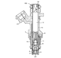
- FIG. 2-FIG. 4 shows an aspect of the structure of the fuel injection valve 105.
- FIG. 2 is a vertical cross-sectional view showing the overall configuration of the fuel injection valve 105
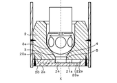
- FIG. 3 is an enlarged vertical cross-sectional view of the tip of the fuel injection valve 105
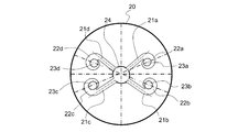
- FIG. 4 is a top view of the orifice plate 20 having an injection hole.
- the fuel injection valve 105 has a structure in which a nozzle body 2 and a valve body 6 are housed in a pipe 13 and the valve body 6 is reciprocated by an electromagnetic coil 11.
- the fuel injection valve 105 includes a magnetic yoke 10 surrounding the electromagnetic coil 11, a core 7 located at the center of the electromagnetic coil 11, a valve body 6, a valve seat surface 3 on which the valve body 6 is seated, and a valve body 6.
- a fuel injection chamber 4 through which fuel flows through the gap between the valve seat surface 3 and an orifice plate 20 arranged downstream of the fuel injection chamber 4 and having a plurality of injection holes 23a, 23b, 23c are provided. ..
- a spring 8 for pressing the valve body 6 against the valve seat surface 3 is provided at the center of the core 7, and the elastic force of the spring 8 is adjusted by the spring adjuster 9.
- the valve body 6 When the electromagnetic coil 11 is not energized, the valve body 6 is seated on the valve seat surface 3, and fuel injection from the injection holes 23a, 23b, 23c is not performed. On the other hand, when the electromagnetic coil 11 is energized, the valve body 6 moves until it comes into contact with the end surface of the core 7 facing the valve body 6 due to the electromagnetic force generated by the electromagnetic coil 11. Then, the movement of the valve body 6 creates a gap between the valve body 6 and the valve seat surface 3, opens a fuel passage, and fuel is injected from the injection holes 23a, 23b, and 23c.
- the fuel injection valve 105 is provided with a fuel passage 12 having a filter 14 at the inlet.
- the outer circumference of the fuel injection valve 105 is covered with a resin mold 15.
- the upper surface 20a of the orifice plate 20 is in contact with the lower surface 2a of the nozzle body 2, and the outer periphery of the contact portion is laser-welded and fixed to the nozzle body 2.
- a fuel introduction hole 5 having a diameter smaller than the diameter ⁇ S of the seat portion 3a of the valve seat surface 3 is provided at the lower end portion of the nozzle body 2.
- the valve seat surface 3 has a conical shape, and a fuel introduction hole 5 is formed in the central portion of the downstream end thereof.
- the valve seat surface 3 and the fuel introduction hole 5 are formed so that the center line of the valve seat surface 3 and the center line of the fuel introduction hole 5 coincide with the valve axis X.
- the fuel introduction hole 5 forms an opening in the lower surface 2a of the nozzle body 2 that communicates with the central chamber 24 of the orifice plate 20.
- the central chamber 24 is a concave portion provided on the upper surface 20a of the orifice plate 20.
- the central chamber 24 is connected to four swivel passages 21a, 21b, 21c, and 21d that are arranged in the circumferential direction and extend radially toward the outer periphery.
- the downstream end of the swivel passage 21a communicates with the swivel chamber 22a
- the downstream end of the swivel passage 21b communicates with the swivel chamber 22b
- the downstream end of the swivel passage 21c communicates with the swivel chamber 22c.
- the downstream end of 21d communicates with the swivel chamber 22d.
- the wall surfaces of the swivel chambers 22a, 22b, 22c, and 22d are formed so that the curvature gradually increases from the upstream to the downstream.
- the swivel chambers 22a, 22b, 22c, and 22d form a spiral fuel passage that gradually approaches the center from the upstream to the downstream.
- Injection holes 23a, 23b, 23c, 23d are opened at the centers of the swivel chambers 22a, 22b, 22c, and 22d, respectively. Further, in the orifice plate 20 shown in FIG.
- the set of the swivel passage 21a and the swivel passage 21b and the set of the swivel passage 21c and the swivel passage 21d are arranged line-symmetrically with respect to the diameter of the orifice plate 20. Will be done. Further, the angle formed by the turning passage 21a and the turning passage 21b and the angle formed by the turning passage 21c and the turning passage 21d are set to be less than 90 deg, respectively.
- the fuel spray injected from the injection holes 23a, 23b, 23c, 23d through the swivel chambers 22a, 22b, 22c, 22d provided in the orifice plate 20 has a spiral flow. Promotes atomization. That is, the swivel chambers 22a, 22b, 22c, 22d, the swivel passages 21a, 21b, 21c, 21d, and the injection holes 23a, 23b, 23c, 23d constitute the atomization promotion mechanism.
- the atomization promotion mechanism is not limited to a mechanism that makes the fuel spray a spiral flow by the swirling chambers 22a, 22b, 22c, 22d.
- known atomization promoting mechanisms such as a mechanism for colliding an air flow with a fuel spray, a mechanism for forming a spiral groove in the valve body of a fuel injection valve, and a mechanism for heating fuel before being injected from an injection hole are provided. It can be adopted as appropriate.
- the arrangement and number of the swivel passages in the orifice plate 20 are not limited to those in FIG. 4, but can be appropriately changed in order to obtain a desired spray shape.
- swivel passages 21a, 21b, 21c, 21d can be arranged at equal intervals in the circumferential direction of the central chamber 24, and the angles formed by the adjacent swivel passages 21 can all be 90 deg.
- the swivel passages 21a, 21b, 21c, 21d and the injection holes 23a, 23b, 23c, 23d can be set to other than four.
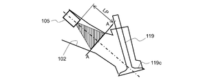
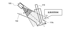
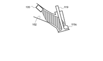
- 5 and 6 are views showing a state in which the fuel injection valve 105 is mounted on the intake port 102 and a spray angle of the fuel injection valve 105.
- the fuel injection valve 105 is attached to the intake port 102 so as to face the direction of the intake valve 119. Specifically, the fuel injection valve 105 is attached to the peripheral wall of the intake port 102 so that the extension line of the axis of the fuel injection valve 105 passes near the center of the umbrella portion 119c of the intake valve 119.
- the axis of the fuel injection valve 105 is the axis connecting the injection direction of the outer surface of the orifice plate 20 through the center of the orifice plate 20 of the fuel injection valve 105 or the center of the valve body 6, or the central axis of the spray pattern. can do.
- the cross-sectional shape of the fuel spray in the cross section perpendicular to the injection direction of the fuel spray at the predetermined position LP at which the directivity of the fuel spray injected from the fuel injection valve 105 is sufficiently reduced (AA cross section in FIG. 5)
- the injection characteristics are set so that the cross-sectional shape of the intake port 102 is reduced to a similar shape.
- the cross-sectional shape of the fuel spray and the cross-sectional shape of the intake port 102 are not limited to similar shapes that overlap each other by scale conversion.
- the cross-sectional shape of the intake port 102 and the cross-sectional shape of the fuel spray in the cross section perpendicular to the injection direction of the fuel spray at the predetermined position LP differ in the width dimension in each of the two axes orthogonal to each other, and the intake air is taken. It can be set so that the longitudinal direction of the cross section of the port 102 and the longitudinal direction of the cross section of the fuel spray match.
- the cross-sectional shape of the fuel spray and the cross-sectional shape of the intake port 102 are not similar, but both are elliptical, and the longitudinal direction of the cross section of the fuel spray and the longitudinal direction of the cross section of the fuel spray are the same. It is not a requirement that the cross-sectional shape of the fuel spray and the cross-sectional shape of the intake port 102 are similar figures that overlap in the scale conversion.
- the virtual extension region extending the region within the spray angle ⁇ of the fuel spray is set to include the inner wall of the intake port 102 closer to the intake valve 119 than the predetermined position LP (see FIG. 6). ..
- the fuel spray is applied to the inner walls of the intake ports 102a and 102b downstream from the predetermined position LP.
- the spray angle is set to collide.
- FIG. 7 is a diagram showing the distribution state of the fuel spray of the fuel injection valve 105 in the intake port 102. That is, in the region where the fuel spray closer to the fuel injection valve 105 than the predetermined position LP and the predetermined position LP has directivity, the cross section of the fuel spray is included in the cross section of the intake port 102, and the fuel spray is included in the intake port 102. Prevents collision with the inner wall of 102. Further, in the region where the directivity of the fuel spray downstream from the predetermined position LP is sufficiently lowered, the injection characteristics of the fuel injection valve 105 so that the fuel spray can be distributed as widely as possible in the intake port 102. , In detail, the spray angle, directivity, etc. are set.
- the predetermined position LP is a value indicating a distance [mm] from the injection holes 23a, 23b, 23c of the fuel injection valve 105 along the axis (central axis of spraying) of the fuel injection valve 105. Further, the predetermined position LP is a position set based on the breakup position Ls of the fuel spray, and will be described in detail later.
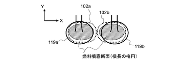
- the internal combustion engine 101 includes two intake ports 102a and 102b and two intake valves 119a and 119b for each cylinder.
- the arrangement direction of the intake ports 102a and 102b is set to the lateral direction (X-axis direction), and the directions orthogonal to the arrangement direction of the intake ports 102a and 102b (intake valves 119a and 119b). Is the vertical direction (Y-axis direction).
- the cross-sectional shape of the intake ports 102a and 102b is such that the spray cross-sectional length (maximum horizontal width) in the horizontal direction (X-axis direction) is larger than the spray cross-sectional length (maximum vertical width) in the vertical direction (Y-axis direction).
- An example shows an internal combustion engine 101 set in a long, horizontally long elliptical shape (an elliptical shape long in the X-axis direction).
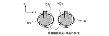
- the cross-sectional shape of the intake ports 102a and 102b is a horizontally long ellipse (an ellipse long in the X-axis direction)
- the cross-sectional shape of the fuel spray at the predetermined position LP is the cross-sectional shape of the intake ports 102a and 102b. Is set to a horizontally long ellipse (a long ellipse in the X-axis direction).
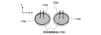
- the cross-sectional shapes of the intake ports 102a and 102b are circular in which the spray cross-sectional length (maximum width) in the horizontal direction (X-axis direction) and the spray cross-sectional length in the vertical direction (Y-axis direction) are substantially equivalent.
- the set internal combustion engine 101 is illustrated.
- the cross-sectional shapes of the intake ports 102a and 102b are circular
- the cross-sectional shape of the fuel spray at the predetermined position LP is set to a circular shape obtained by reducing the cross-sectional shape of the intake ports 102a and 102b.
- the cross-sectional shape of the intake ports 102a and 102b is such that the spray cross-sectional length (maximum horizontal width) in the horizontal direction (X-axis direction) is larger than the spray cross-sectional length (maximum vertical width) in the vertical direction (Y-axis direction).
- An example shows an internal combustion engine 101 having a short, vertically long oval shape (long oval shape in the Y-axis direction).
- the cross-sectional shape of the intake ports 102a and 102b is a vertically long ellipse (an ellipse long in the Y-axis direction)
- the cross-sectional shape of the fuel spray at the predetermined position LP is the cross-sectional shape of the intake ports 102a and 102b. Is set to a reduced vertically long ellipse (in other words, an ellipse long in the Y-axis direction).
- the aspect ratio of the cross-sectional shape of the fuel spray at the predetermined position LP is equivalent to the aspect ratio of the cross-sectional shapes of the intake ports 102a and 102b, so that the cross-sectional shape of the fuel spray is the intake port 102a.
- 102b is set to have a similar shape with a reduced cross-sectional shape.
- the length of the cross-sectional shape of the fuel spray in the vertical direction (Y-axis direction) is represented by Sy
- the length in the horizontal direction (X-axis direction) is represented by Sx
- the intake ports 102a and 102b are assumed that the length of the cross-sectional shape in the vertical direction (Y-axis direction) is represented by Py and the length in the horizontal direction (X-axis direction) is represented by Px.
- the aspect ratio of the cross-sectional shape of the fuel spray is Sy / Sx
- the aspect ratio of the cross-sectional shapes of the intake ports 102a and 102b is Py / Px.
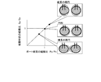
- FIG. 12 shows the correlation between the aspect ratio of the cross-sectional shape of the fuel spray and the aspect ratio of the cross-sectional shapes of the intake ports 102a and 102b.
- the cross-sectional shapes of the intake ports 102a and 102b shown in FIG. 8 are elliptical in the horizontal direction (X-axis direction)
- the aspect ratio Py / Px is less than 1
- the cross-sectional shape of the fuel spray is vertical and horizontal.
- the spray shape is also set so that the ratio Sy / Sx has a value equivalent to the aspect ratio Py / Px.
- the aspect ratio Py / Px is 1, and the aspect ratio Sy / Sx of the fuel spray is sprayed so as to be 1.
- the shape is set.
- the cross-sectional shape of the intake ports 102a and 102b shown in FIG. 10 is an elliptical shape that is long in the vertical direction (Y-axis direction)
- the aspect ratio Py / Px becomes a value exceeding 1
- the spray shape is also set so that the aspect ratio Sy / Sx of is also the same value as the aspect ratio Py / Px.
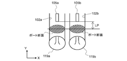
- FIG. 13 shows a specific position of the aspect ratio Py / Px of the intake ports 102a and 102b when the intake ports 102a and 102b of the internal combustion engine 101 are straight ports, respectively.
- the straight port has a shape in which each of the intake ports 102a and 102b of the internal combustion engine 101 extends from the installation position of the fuel injection valve 105 to the intake valves 119a and 119b without branching.
- the internal combustion engine 101 includes, as the fuel injection valve 105, a fuel injection valve 105a for injecting fuel into the intake port 102a and a fuel injection valve 105a for injecting fuel into the intake port 102b.
- the intake ports 102a and 102b of the internal combustion engine 101 are straight ports, the aspect ratio Py / Px of the cross-sectional shape of the intake ports 102a and 102b is set to the longitudinal length Py of the intake ports 102a and 102b at the predetermined position LP. It is the ratio with the lateral length Px of the intake ports 102a and 102b at the predetermined position LP.
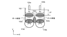
- FIG. 14 shows a specific position of the aspect ratio Py / Px of the intake port 102 when the intake port 102 of the internal combustion engine 101 is a siamese port (siamese type).
- the siamese port has a shape in which the intake port 102 of the internal combustion engine 101 branches into two intake ports 102a and 102b at a branch portion 102c in the middle, and further, in the example of FIG. 14, the installation position and predetermined position of the fuel injection valve 105.
- the branch portion 102c is set downstream of the position LP.
- the internal combustion engine 101 uses the fuel injection valve 105a for injecting fuel into the intake port 102a and the fuel injection valve 105a for injecting fuel into the intake port 102b as the fuel injection valve 105 upstream of the branch portion 102c. It is arranged in each of the intake ports 102 of the above.
- the lateral length Px of the cross section of the intake port 102 is set to the intake port after branching closer to the intake valves 119a and 119b than the branch portion 102c.
- the lateral lengths of 102a and 102b are set respectively.
- the spray characteristics are set so that the breakup position Ls of the fuel injection valve 105 is upstream of the intake valves 119a and 119b.
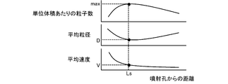
- the break-up position Ls is a position where the shape of the fuel spray begins to be disturbed due to the weakening of the directivity of the spray particles from the shape of the fuel spray arranged in a conical shape immediately after injection.
- FIG. 15 shows the correlation between the distance of the fuel injection valve 105 from the injection hole (injection point) and the number of particles per unit volume of the fuel spray, the average particle size, and the average velocity.
- the number of particles, the particle size, and the velocity can be quantified according to the distance from the injection hole from the measurement results of the particle size distribution, the particle density, and the particle velocity by the laser diffraction confusion method, the microscope method, or the like.
- the particle size of the spray is generally quantified by the Sauter mean diameter (SMD or D32), but the number average diameter (D10), median diameter (D50), and 90% particle size (D90) are used. Can be quantified using.
- the breakup position Ls is a unit of fuel spraying with respect to a change in distance when the number of particles per unit volume of fuel spraying, the average particle size, and the average speed are obtained for each distance from the injection hole of the fuel injection valve 105. It can be defined as a position where the number of particles per volume becomes a maximum value, a position where the average particle size becomes a minimum value with respect to a change in distance, or a position where the average speed becomes a predetermined speed or less. That is, the region after the break-up position Ls is a region where the directivity of the fuel spray is sufficiently lowered, and in such a region, the fuel spray floats in the intake ports 102a and 102b toward the intake valve 119. It will flow.
- the inner wall of the intake port 102 closer to the intake valve 119 than the break-up position Ls is included in the virtual extension region that extends the region within the range of the spray angle ⁇ of the fuel spray.
- the fuel spray can be widely distributed inside the intake ports 102a and 102b while suppressing the adhesion of fuel to the inner walls of the intake ports 102a and 102b. If the fuel is sprayed at a wide angle so that the fuel spray collides with the inner walls of the intake ports 102a and 102b before the break-up position Ls, the fuel spray can be widely distributed in the intake ports 102a and 102b, but the intake air is intake. Fuel adheres to the inner walls of the ports 102a and 102b more often.
- the directivity of the fuel spray is sufficiently lowered thereafter, so that the fuel spray is made into the intake ports 102a and 102b.
- the penetration force of the fuel spray is a force that correlates with the product value of the diameter of the fuel spray particles and the spray speed, the fuel spray maintains a certain degree of directivity at the breakup position Ls, and the breakup occurs. Even if the position Ls is used as the reference position for the injection characteristics, it may not be possible to sufficiently suppress fuel adhesion to the inner walls of the intake ports 102a and 102b.
- the reference position for spray formation is based on the break-up position Ls, and further, the average particle size and average velocity at the break-up position Ls, in other words, the penetration force of the fuel spray at the break-up position Ls, are taken into consideration.
- the predetermined position LP as is set.
- FIG. 16 shows the setting characteristics of the predetermined position LP based on the break-up position Ls and the average particle size and the average velocity at the break-up position Ls.
- the horizontal axis of FIG. 16 is the break-up position Ls. Further, the vertical axis of FIG. 16 is a value obtained by multiplying the average particle size at the breakup position Ls and the average velocity at the breakup position Ls, and is a value that correlates with the penetration force of the fuel spray at the breakup position Ls. Is.
- the breakup position Ls is the same, if the product value of the average particle size and the average velocity at the breakup position Ls, that is, the penetration force is large, the predetermined position LP is changed to a farther position.
- the break-up position Ls is set to the predetermined position LP
- the cross-sectional shape of the fuel spray at the predetermined position LP is changed to the intake ports 102a and 102b.
- the fuel spray maintains the directivity even after the predetermined position LP, so that the fuel spray may collide with and adhere to the inner walls of the intake ports 102a and 102b.
- the predetermined position LP is changed to a farther distance, and the cross-sectional shape of the fuel spray is the intake port at the predetermined position LP.
- the injection characteristics are set so as to be included in the cross sections of 102a and 102b.
- the fuel spray can be evenly distributed in the ports 102a and 102b. Therefore, the fuel spray in the intake ports 102a and 102b and the premixing of air are made uniform to improve the homogeneity of the in-cylinder air-fuel mixture, which has effects such as reduction of unburned fuel, suppression of knocking, and improvement of combustibility. ..
- the inner wall of the intake ports 102a and 102b closer to the intake valves 119a and 119b than the predetermined position LP can be set in the virtual extension region in which the region within the spray angle of the fuel spray is extended.
- the breakup position Ls of the fuel spray injected from the fuel injection valve 105 is set to be in the intake ports 102a and 102b, and the fuel spray is performed at the predetermined position LP based on the breakup position Ls.
- the intake port 102a will be after the directivity of the fuel spray is sufficiently lowered.
- the fuel spray can be widely diffused in the 102b, and the premixing of the fuel spray and the air in the intake port 102 can be made uniform.
- the injection end timing by the fuel injection valve 105 can be set before the intake top dead center. If the injection end timing by the fuel injection valve 105 is set before the intake top dead point, that is, before the flow of intake air toward the inside of the cylinder occurs, the fuel spray injected from the fuel injection valve 105 is sent into the intake ports 102a and 102b. After making the premix of the fuel spray and air uniform, the premixer can be sucked into the cylinder.
- the fact that the cross-sectional shape of the fuel spray is a reduced cross-sectional shape of the intake port means that the aspect ratio of the cross section of the fuel spray is substantially the same as the aspect ratio of the cross section of the intake port. It does not require that the shapes match perfectly by showing, enlarging or reducing. Further, the fact that the cross-sectional shape of the fuel spray is a similar shape obtained by reducing the cross-sectional shape of the intake port 102 indicates that the cross-sectional shapes of the fuel sprays overlap each other by scale conversion without rotational movement, and one of them is a vertically long ellipse.
- the fuel injection valve 105 is provided at each intake port 102a and 102b, respectively.
- one fuel injection valve 105 that injects in two directions toward each of the intake ports 102a and 102b can be provided.
- the predetermined position LP can be set to the break-up position Ls, and the predetermined position LP can be set based on the break-up position Ls and the average particle size at the break-up position Ls, and the break-up position Ls. And the average speed at the breakup position Ls, the predetermined position LP can be set.
Landscapes
- Engineering & Computer Science (AREA)
- Chemical & Material Sciences (AREA)
- Combustion & Propulsion (AREA)
- Mechanical Engineering (AREA)
- General Engineering & Computer Science (AREA)
- Fuel-Injection Apparatus (AREA)
Abstract
Description
また、本発明に係るポート噴射式内燃機関は、その一態様として、内燃機関の吸気ポートに燃料を噴射する燃料噴射弁を備えたポート噴射式内燃機関であって、前記燃料噴射弁から噴射される燃料噴霧のブレイクアップ位置が吸気弁よりも上流に設定され、前記ブレイクアップ位置に基づく所定位置での前記燃料噴霧の噴射方向に直角な断面における前記燃料噴霧の断面形状が、前記吸気ポートの断面形状を縮小した形状である。
図1は、内燃機関101の概略構成図である。
内燃機関101は、自動車に駆動源として搭載される火花点火ガソリン機関であって、例えば、直列4気筒機関である。
但し、内燃機関101の気筒数を4気筒に限定するものではなく、また、内燃機関101は、水平対向型やV型であってもよい。
燃料噴射弁105は、吸気弁119の上流の吸気ポート102に、吸気弁119を指向して取り付けられ、吸気ポート102内に燃料を噴射する。
つまり、図1の内燃機関101は、所謂ポート噴射式内燃機関である。
エアークリーナ107を通過した空気は、電制スロットル108のスロットルバルブ108aで流量を調節され、燃料噴射弁105から噴射された燃料とともに吸気弁119を介して燃焼室110に吸引される。
クランク角センサ106は、リングギア114の突起を検出することで、クランクシャフト117の所定回転角毎に立ち上がるパルス信号であるクランク角信号CAを出力する。
また、内燃機関101の排気管103に配置される触媒コンバータ112は、三元触媒を内蔵し、内燃機関101の排気を浄化する。
また、排気温度センサ116は、触媒コンバータ112の上流の排気管103に配置され、触媒コンバータ112の入口での排気温度[℃]の情報である排気温度信号TEXを出力する。
エンジン制御装置113は、MPU(Microprocessor Unit)126、ROM(Read Only Memory)127、RAM(Random Access Memory)128を含むマイクロコンピュータを備えた電子制御装置である。
エンジン制御装置113は、取得した情報に基づいて演算を行い、演算した結果を点火装置104、燃料噴射弁105、電制スロットル108などに出力して内燃機関101の運転を制御するコントロール部としての機能を有する。
そして、エンジン制御装置113は、取得した各種信号に基づいて点火時期や燃料噴射量などを演算して、点火時期を制御する点火制御信号を点火装置104に出力し、燃料噴射量を制御する噴射パルス信号(換言すれば、空燃比制御信号)を燃料噴射弁105に出力する。
アナログ入力回路120は、吸入空気流量信号QAR、スロットル開度信号TPS、空燃比信号RABF、排気温度信号TEX、冷却水温度信号TWなどのアナログ検出信号の取得処理を行う。
また、デジタル入力回路122が取得処理するデジタル検出信号であるクランク角信号CAなどは、I/O回路124を介してバス125上に出力される。
MPU126には、クロックジェネレータ130からクロック信号が供給され、MPU126は、クロック信号に同期して様々な演算や処理を実行する。
ROM127が記憶する情報は、バス125を介してRAM128及びMPU126に読み込まれる。
なお、タイマ/カウンタ129は、時間の測定や様々な回数の測定などに用いられる。
MPU126による演算結果である点火制御信号や空燃比制御信号などの操作量の信号は、バス125上に出力された後、I/O回路124を介して出力回路123から点火装置104、燃料噴射弁105、電制スロットル108などに供給される。
図2は燃料噴射弁105の全体構成を示した縦断面図、図3は燃料噴射弁105の先端部を拡大した縦断面図、図4は噴射孔を有するオリフィスプレート20の上面図である。
燃料噴射弁105は、パイプ13にノズル体2、弁体6を収容し、弁体6を電磁コイル11で往復動作させる構造である。
また、コア7の中心には、弁体6を弁座面3に押圧するスプリング8が備えられ、スプリング8の弾性力はスプリングアジャスタ9によって調整される。
一方、電磁コイル11に通電されると、電磁コイル11が発生する電磁力によって弁体6が対面するコア7の端面に接触するまで移動する。
そして、係る弁体6の移動によって弁体6と弁座面3の間に隙間が生じて燃料通路が開き、噴射孔23a,23b,23cから燃料が噴射される。
また、燃料噴射弁105の外周は樹脂モールド15によって被覆されている。
オリフィスプレート20は、その上面20aがノズル体2の下面2aに接触しており、この接触部分の外周をレーザ溶接してノズル体2に固定されている。
弁座面3は円錐形状をしており、その下流端中央部に燃料導入孔5が形成されている。
燃料導入孔5によって、ノズル体2の下面2aにオリフィスプレート20の中央室24に連通する開口が形成される。
中央室24は、オリフィスプレート20の上面20aに設けられた凹形状部である。
そして、旋回用通路21aの下流端は旋回室22aに連通し、旋回用通路21bの下流端は旋回室22bに連通し、旋回用通路21cの下流端は旋回室22cに連通し、旋回用通路21dの下流端は旋回室22dに連通する。
旋回室22a,22b,22c,22dの中心には、噴射孔23a,23b,23c,23dがそれぞれ開口している。
また、図4に示すオリフィスプレート20において、旋回用通路21a及び旋回用通路21bの組と、旋回用通路21c及び旋回用通路21dの組とが、オリフィスプレート20の直径を挟んで線対称に配置される。更に、旋回用通路21aと旋回用通路21bとがなす角度、及び、旋回用通路21c及び旋回用通路21dがなす角度が、それぞれ90degを下回るように設定してある。
つまり、旋回室22a,22b,22c,22d、旋回用通路21a,21b,21c,21d、噴射孔23a,23b,23c,23dが微粒化促進機構を構成する。
また、オリフィスプレート20における旋回用通路の配置や個数を、図4のものに限定するものではなく、所望の噴霧形状とするために適宜変更することができる。
例えば、4個の旋回用通路21a,21b,21c,21dを、中央室24の周方向に等間隔に配置し、隣接する旋回用通路21がなす角度を全て90degとすることができ、また、旋回用通路21a,21b,21c,21d及び噴射孔23a,23b,23c,23dを4個以外に設定することもできる。
図5及び図6は、燃料噴射弁105の吸気ポート102への搭載状態、及び、燃料噴射弁105の噴霧角を示す図である。
詳細には、燃料噴射弁105の軸心の延長線が吸気弁119の傘部119cの中央付近を通るように、燃料噴射弁105が吸気ポート102の周壁に取り付けられる。
なお、燃料噴射弁105の軸心は、燃料噴射弁105のオリフィスプレート20の中心又は弁体6の中心を通ってオリフィスプレート20の外面の噴射方向を結ぶ軸線、又は、噴霧パターンの中心軸線とすることができる。
但し、燃料噴霧の断面形状と吸気ポート102の断面形状とを、スケール変換によって相互が重なる相似形状に限定するものではない。
つまり、吸気ポート102の断面形状、及び、所定位置LPでの燃料噴霧の噴射方向に直角な断面における燃料噴霧の断面形状が、相互に直交する2軸それぞれの方向での幅寸法が異なり、吸気ポート102の横断面の長手方向と燃料噴霧の横断面の長手方向とが合うように設定することができる。
例えば、燃料噴霧の断面形状と吸気ポート102の断面形状とが相似ではないが、共に楕円形であって、燃料噴霧の断面の長手方向と、燃料噴霧の断面の長手方向とが同じ方向となるように設定することができ、燃料噴霧の断面形状と吸気ポート102の断面形状とがスケール変換で重なる相似形であることを要件とするものではない。
換言すれば、燃料噴霧が指向性を維持したまま吸気弁119a、119bにまで到達する貫徹力を有すると仮定した場合に、所定位置LPよりも下流の吸気ポート102a、102bの内壁に燃料噴霧が衝突する噴霧角に設定されている。
つまり、所定位置LP及び所定位置LPよりも燃料噴射弁105寄りの燃料噴霧が指向性を有する領域では、燃料噴霧の断面が吸気ポート102の断面に内包されるようにして、燃料噴霧が吸気ポート102の内壁に衝突することを抑止する。また、所定位置LPよりも下流の燃料噴霧の指向性が十分に低下する領域では、吸気ポート102内に燃料噴霧を可及的に広く分布させることができるように、燃料噴射弁105の噴射特性、詳細には、噴霧角、指向性などが設定されている。
また、所定位置LPは、燃料噴霧のブレイクアップ位置Lsに基づき設定される位置であり、後で詳細に説明する。
ここで、内燃機関101は、各気筒それぞれに2つの吸気ポート102a、102b及び2つの吸気弁119a、119bを備える。
そして、本願においては、吸気ポート102a、102b(吸気弁119a、119b)の並び方向を横方向(X軸方向)とし、吸気ポート102a、102b(吸気弁119a、119b)の並び方向に直交する方向を縦方向(Y軸方向)とする。
このように、吸気ポート102a、102bの断面形状が横長の楕円形(X軸方向に長い楕円形)である場合、所定位置LPでの燃料噴霧の断面形状は、吸気ポート102a、102bの断面形状を縮小した横長の楕円形(X軸方向に長い楕円形)に設定される。
このように、吸気ポート102a、102bの断面形状が円形である場合、所定位置LPでの燃料噴霧の断面形状は、吸気ポート102a、102bの断面形状を縮小した円形に設定される。
このように、吸気ポート102a、102bの断面形状が縦長の楕円形(Y軸方向に長い楕円形)である場合、所定位置LPでの燃料噴霧の断面形状は、吸気ポート102a、102bの断面形状を縮小した縦長の楕円形(換言すれば、Y軸方向に長い楕円形)に設定される。
このとき、燃料噴霧の断面形状の縦横比はSy/Sxとなり、吸気ポート102a、102bの断面形状の縦横比はPy/Pxとなる。
図8に示した、吸気ポート102a、102bの断面形状が横方向(X軸方向)に長い楕円形である場合、縦横比Py/Pxは1未満の値になり、燃料噴霧の断面形状の縦横比Sy/Sxも、縦横比Py/Pxと同等の値になるように噴霧形状が設定される。
また、図10に示した、吸気ポート102a、102bの断面形状が縦方向(Y軸方向)に長い楕円形である場合、縦横比Py/Pxは1を超える値になり、燃料噴霧の断面形状の縦横比Sy/Sxも、縦横比Py/Pxと同等の値になるように噴霧形状が設定される。
図13は、内燃機関101の吸気ポート102a、102bそれぞれがストレートポートである場合での吸気ポート102a、102bの縦横比Py/Pxの特定位置を示す。
ストレートポートとは、内燃機関101の吸気ポート102a、102bそれぞれが、燃料噴射弁105の設置位置から分岐することなく吸気弁119a、119bにまで延びる形状である。
内燃機関101の吸気ポート102a、102bがストレートポートである場合、吸気ポート102a、102bの断面形状の縦横比Py/Pxを、所定位置LPでの吸気ポート102a、102bの縦方向長さPyと、所定位置LPでの吸気ポート102a、102bの横方向長さPxとの比とする。
サイアミーズポートとは、内燃機関101の吸気ポート102が途中の分岐部102cで2つの吸気ポート102a、102bに分岐する形状であり、更に、図14の例では、燃料噴射弁105の設置位置及び所定位置LPの下流に分岐部102cが設定される。
係るサイアミーズポートである場合、所定位置LPが分岐部102cの上流であるため、吸気ポート102の断面の横方向長さPxを、分岐部102cよりも吸気弁119a、119bに近い分岐後の吸気ポート102a、102bぞれぞれの横方向長さとする。
内燃機関101において、燃料噴射弁105のブレイクアップ(breakup)位置Lsが、吸気弁119a、119bよりも上流になるように噴霧特性が設定されている。
ブレイクアップ位置Lsは、噴射直後の円錐状に整った燃料噴霧の形から、噴霧粒子の指向性が弱まることで燃料噴霧の形に乱れが生じ始める位置である。
なお、レーザ回析錯乱法、顕微鏡法などによる粒径分布、粒子密集度、粒子速度の計測結果から、噴射孔からの距離に応じた粒子数、粒径、速度を定量化することができる。
また、噴霧の粒径は、ザウター平均粒径(SMD若しくはD32)で定量化するのが一般的であるが、個数平均径(D10)、メディアン径(D50)、90%粒子径(D90)を用いて定量化することができる。
つまり、ブレイクアップ位置Ls以降の領域は、燃料噴霧の指向性が十分に低下する領域であって、係る領域において、燃料噴霧は吸気ポート102a、102b内に漂うようにして吸気弁119に向けて流れることになる。
ブレイクアップ位置Lsの手前で燃料噴霧が吸気ポート102a、102bの内壁に衝突するように広角に燃料を噴霧させると、吸気ポート102a、102b内に燃料噴霧を広く分布させることができるとしても、吸気ポート102a、102bの内壁への燃料付着が多くなってしまう。
但し、燃料噴霧の貫徹力は、燃料噴霧粒子の径と噴霧速度との乗算値に相関する力であるから、係るブレイクアップ位置Lsで燃料噴霧がある程度の指向性を維持していて、ブレイクアップ位置Lsを噴射特性の基準位置としても、吸気ポート102a、102bの内壁への燃料付着を十分に抑制できない場合がある。
図16は、ブレイクアップ位置Ls、及び、ブレイクアップ位置Lsでの平均粒径及び平均速度に基づく、所定位置LPの設定特性を示す。
また、図16の縦軸は、ブレイクアップ位置Lsでの平均粒径とブレイクアップ位置Lsでの平均速度との乗算値であって、ブレイクアップ位置Lsでの燃料噴霧の貫徹力に相関する値である。
換言すれば、ブレイクアップ位置Lsが同じでも、ブレイクアップ位置Lsでの平均粒径と平均速度との乗算値、つまり、貫徹力が大きいと、所定位置LPをより遠い位置に変更する。
そこで、ブレイクアップ位置Lsでの平均粒径及び/又は平均速度が大きく指向性を維持する場合、所定位置LPをより遠くに変更して、係る所定位置LPで、燃料噴霧の断面形状が吸気ポート102a、102bの断面に内包されように噴射特性を設定する。
したがって、吸気ポート102a、102b内の燃料噴霧と空気の予混合が均一化して筒内混合気の均質性が改善され、未燃燃料の減少、ノッキングの抑止、燃焼性の改善などの効果を奏する。
また、好ましい実施形態を参照して本発明の内容を具体的に説明したが、本発明の基本的技術思想及び教示に基づいて、当業者であれば、種々の変形態様を採り得ることは自明である。
この場合も、燃料噴射弁105から噴射される燃料噴霧のブレイクアップ位置Lsが、吸気ポート102a、102b中になるように設定され、かつ、ブレイクアップ位置Lsに基づく所定位置LPでの燃料噴霧の噴射方向に直角な断面における燃料噴霧の断面形状が、吸気ポート102a、102bの断面形状を縮小した相似形状に設定されていれば、燃料噴霧の指向性が十分に低下した後において、吸気ポート102a、102b内に燃料噴霧を広く拡散させ、吸気ポート102内の燃料噴霧と空気との予混合の均一化を図ることができる。
燃料噴射弁105による噴射終了タイミングを、吸気上死点前、つまり、筒内に向かう吸気の流れが生じる前に設定すれば、燃料噴射弁105から噴射された燃料噴霧を吸気ポート102a、102b内に広く拡散させ、燃料噴霧と空気との予混合を均一化してから、予混合気を筒内に吸引させることができる。
また、燃料噴霧の断面形状が吸気ポート102の断面形状を縮小した相似形状であるという事項は、相互の断面形状が回転移動を伴わずにスケール変換によって重なることを示し、一方が縦長の楕円(換言すれば、Y軸方向に長い楕円)で、他方が横長の楕円(換言すれば、X軸方向に長い楕円)である場合を含まない。
また、所定位置LPを、ブレイクアップ位置Lsに設定することができ、更に、ブレイクアップ位置Lsとブレイクアップ位置Lsでの平均粒径とに基づき所定位置LPを設定でき、また、ブレイクアップ位置Lsとブレイクアップ位置Lsでの平均速度とに基づき所定位置LPを設定できる。
Claims (13)
- 内燃機関の吸気ポートに燃料を噴射する燃料噴射弁であって、
前記燃料噴射弁から噴射される燃料噴霧のブレイクアップ位置が、吸気弁よりも上流に設定されている、
燃料噴射弁。 - 前記吸気ポートの断面形状、及び、前記ブレイクアップ位置に基づく所定位置での前記燃料噴霧の噴射方向に直角な断面における燃料噴霧の断面形状は、相互に直交する2軸それぞれの方向での幅寸法が異なり、
前記吸気ポートの横断面の長手方向と前記燃料噴霧の横断面の長手方向とが合うように設定されている、
請求項1に記載の燃料噴射弁。 - 前記ブレイクアップ位置に基づく所定位置での前記燃料噴霧の噴射方向に直角な断面における前記燃料噴霧の断面形状が、前記吸気ポートの断面形状を縮小した形状である、
請求項1に記載の燃料噴射弁。 - 前記所定位置は、前記ブレイクアップ位置、及び、前記ブレイクアップ位置での前記燃料噴霧の平均粒径と前記ブレイクアップ位置での前記燃料噴霧の平均速度との少なくも一方に応じた位置である、
請求項2記載の燃料噴射弁。 - 前記所定位置は、前記ブレイクアップ位置での前記燃料噴霧の平均粒径が大きいほど前記吸気弁により近い位置に設定され、前記ブレイクアップ位置での前記燃料噴霧の平均速度が速いほど前記吸気弁により近い位置に設定される、
請求項4記載の燃料噴射弁。 - 前記ブレイクアップ位置は、前記燃料噴霧の平均粒径又は単位体積当たりの粒子数が極値となる位置である、
請求項4記載の燃料噴射弁。 - 前記吸気ポートは、前記燃料噴射弁の下流の分岐部で2つに分岐し、
前記吸気ポートの断面形状は、前記分岐部よりも前記吸気弁寄りでの断面形状である、
請求項2記載の燃料噴射弁。 - 前記吸気ポートは、ストレートポートであり、
前記吸気ポートの断面形状は、前記所定位置での断面形状である、
請求項2記載の燃料噴射弁。 - 前記燃料噴霧の噴霧角の範囲内の領域を延長した仮想延長領域内に、前記所定位置よりも前記吸気弁寄りの前記吸気ポートの内壁を含むように設定されている、
請求項2記載の燃料噴射弁。 - 微粒化した燃料を噴射するための微粒化促進機構を備えた、
請求項2記載の燃料噴射弁。 - 内燃機関の吸気ポートに燃料を噴射する燃料噴射弁を備えたポート噴射式内燃機関であって、
前記燃料噴射弁から噴射される燃料噴霧のブレイクアップ位置が吸気弁よりも上流に設定され、
前記吸気ポートの断面形状、及び、前記ブレイクアップ位置に基づく所定位置での前記燃料噴霧の噴射方向に直角な断面における断面形状は、相互に直交する2軸それぞれの方向での幅寸法が異なり、前記吸気ポートの横断面の長手方向と前記燃料噴霧の横断面の長手方向とが合うように設定されている、
ポート噴射式内燃機関。 - 内燃機関の吸気ポートに燃料を噴射する燃料噴射弁を備えたポート噴射式内燃機関であって、
前記燃料噴射弁から噴射される燃料噴霧のブレイクアップ位置が吸気弁よりも上流に設定され、
前記ブレイクアップ位置に基づく所定位置での前記燃料噴霧の噴射方向に直角な断面における前記燃料噴霧の断面形状が、前記吸気ポートの断面形状を縮小した形状である、
ポート噴射式内燃機関。 - 前記燃料噴霧の噴霧角の範囲内の領域を延長した仮想延長領域内に、前記所定位置よりも前記吸気弁寄りの前記吸気ポートの内壁を含むように設定されている、
請求項11記載のポート噴射式内燃機関。
Priority Applications (2)
| Application Number | Priority Date | Filing Date | Title |
|---|---|---|---|
| BR112022004246-9A BR112022004246B1 (pt) | 2019-11-18 | 2020-11-10 | Válvula de injeção de combustível e motor de combustão interna com porta de injeção |
| JP2021558309A JP7280971B2 (ja) | 2019-11-18 | 2020-11-10 | 燃料噴射弁及びポート噴射式内燃機関 |
Applications Claiming Priority (2)
| Application Number | Priority Date | Filing Date | Title |
|---|---|---|---|
| JP2019207788 | 2019-11-18 | ||
| JP2019-207788 | 2019-11-18 |
Publications (1)
| Publication Number | Publication Date |
|---|---|
| WO2021100545A1 true WO2021100545A1 (ja) | 2021-05-27 |
Family
ID=75981222
Family Applications (1)
| Application Number | Title | Priority Date | Filing Date |
|---|---|---|---|
| PCT/JP2020/041867 Ceased WO2021100545A1 (ja) | 2019-11-18 | 2020-11-10 | 燃料噴射弁及びポート噴射式内燃機関 |
Country Status (2)
| Country | Link |
|---|---|
| JP (1) | JP7280971B2 (ja) |
| WO (1) | WO2021100545A1 (ja) |
Cited By (1)
| Publication number | Priority date | Publication date | Assignee | Title |
|---|---|---|---|---|
| CN115238483A (zh) * | 2022-07-08 | 2022-10-25 | 中国人民解放军国防科技大学 | 大尺度超燃冲压发动机液体燃料喷注段优化设计方法 |
Citations (2)
| Publication number | Priority date | Publication date | Assignee | Title |
|---|---|---|---|---|
| JPH0972264A (ja) * | 1995-09-07 | 1997-03-18 | Hitachi Ltd | 内燃機関の燃料供給装置及び燃料供給方法 |
| JP2015014245A (ja) * | 2013-07-05 | 2015-01-22 | 三菱電機株式会社 | 流体噴射弁及び噴霧生成装置 |
-
2020
- 2020-11-10 WO PCT/JP2020/041867 patent/WO2021100545A1/ja not_active Ceased
- 2020-11-10 JP JP2021558309A patent/JP7280971B2/ja active Active
Patent Citations (2)
| Publication number | Priority date | Publication date | Assignee | Title |
|---|---|---|---|---|
| JPH0972264A (ja) * | 1995-09-07 | 1997-03-18 | Hitachi Ltd | 内燃機関の燃料供給装置及び燃料供給方法 |
| JP2015014245A (ja) * | 2013-07-05 | 2015-01-22 | 三菱電機株式会社 | 流体噴射弁及び噴霧生成装置 |
Cited By (1)
| Publication number | Priority date | Publication date | Assignee | Title |
|---|---|---|---|---|
| CN115238483A (zh) * | 2022-07-08 | 2022-10-25 | 中国人民解放军国防科技大学 | 大尺度超燃冲压发动机液体燃料喷注段优化设计方法 |
Also Published As
| Publication number | Publication date |
|---|---|
| BR112022004246A2 (pt) | 2022-05-31 |
| JPWO2021100545A1 (ja) | 2021-05-27 |
| JP7280971B2 (ja) | 2023-05-24 |
Similar Documents
| Publication | Publication Date | Title |
|---|---|---|
| US7770556B2 (en) | Multi-hole injector, in-cylinder gasoline injection type internal combustion engine and control method for the engine | |
| US20120152205A1 (en) | Fuel injection valve and internal combustion engine | |
| CN108691682B (zh) | 内燃机的控制装置 | |
| JP2008202483A (ja) | 筒内噴射型の内燃機関、及び筒内噴射型の内燃機関に用いるインジェクタ | |
| JP2010249125A (ja) | 燃料噴射弁 | |
| JP6508240B2 (ja) | 火花点火式内燃機関 | |
| EP2025919B1 (en) | Diesel engine, fuel injection nozzle and fuel injection method therefor | |
| US20030127069A1 (en) | Direct fuel injection engine | |
| US7237527B2 (en) | Fuel injector for an internal combustion engine | |
| JP7280971B2 (ja) | 燃料噴射弁及びポート噴射式内燃機関 | |
| US6672276B2 (en) | Direct fuel injection engine | |
| US6659074B2 (en) | Spark ignition direct injection engine with shaped multihole injectors | |
| JP2007138779A (ja) | 筒内噴射内燃機関 | |
| US10378464B2 (en) | Control device for internal combustion engine | |
| JP2018003752A (ja) | 内燃機関 | |
| JP2006037794A (ja) | 筒内直接噴射式火花点火内燃機関 | |
| JP2005171794A (ja) | 直接噴射式燃料噴射装置 | |
| JP7365512B2 (ja) | 内燃機関 | |
| JPH0122905Y2 (ja) | ||
| JP2003314413A (ja) | 内燃機関の燃料噴射装置 | |
| JP7591160B2 (ja) | 燃料噴射制御装置及び燃料噴射制御方法 | |
| US6938607B1 (en) | Fuel injection apparatus and control method thereof | |
| JP2006057604A (ja) | 筒内直噴式内燃機関 | |
| BR112022004246B1 (pt) | Válvula de injeção de combustível e motor de combustão interna com porta de injeção | |
| JPH08105326A (ja) | 直噴型火花点火式内燃機関 |
Legal Events
| Date | Code | Title | Description |
|---|---|---|---|
| 121 | Ep: the epo has been informed by wipo that ep was designated in this application |
Ref document number: 20889293 Country of ref document: EP Kind code of ref document: A1 |
|
| ENP | Entry into the national phase |
Ref document number: 2021558309 Country of ref document: JP Kind code of ref document: A |
|
| REG | Reference to national code |
Ref country code: BR Ref legal event code: B01A Ref document number: 112022004246 Country of ref document: BR |
|
| ENP | Entry into the national phase |
Ref document number: 112022004246 Country of ref document: BR Kind code of ref document: A2 Effective date: 20220308 |
|
| NENP | Non-entry into the national phase |
Ref country code: DE |
|
| 122 | Ep: pct application non-entry in european phase |
Ref document number: 20889293 Country of ref document: EP Kind code of ref document: A1 |