WO2021090525A1 - Beveling cutter and method for beveling workpiece - Google Patents
Beveling cutter and method for beveling workpiece Download PDFInfo
- Publication number
- WO2021090525A1 WO2021090525A1 PCT/JP2020/018620 JP2020018620W WO2021090525A1 WO 2021090525 A1 WO2021090525 A1 WO 2021090525A1 JP 2020018620 W JP2020018620 W JP 2020018620W WO 2021090525 A1 WO2021090525 A1 WO 2021090525A1
- Authority
- WO
- WIPO (PCT)
- Prior art keywords
- cutting edge
- edge portion
- angle
- outer peripheral
- peripheral side
- Prior art date
Links
- 238000000034 method Methods 0.000 title claims description 6
- 230000002093 peripheral effect Effects 0.000 claims abstract description 129
- 238000005452 bending Methods 0.000 claims abstract description 15
- 239000002699 waste material Substances 0.000 claims description 23
- 230000015572 biosynthetic process Effects 0.000 abstract description 3
- 230000000052 comparative effect Effects 0.000 description 9
- 230000000694 effects Effects 0.000 description 9
- 238000010586 diagram Methods 0.000 description 4
- 238000007599 discharging Methods 0.000 description 2
- 240000001973 Ficus microcarpa Species 0.000 description 1
- 230000001154 acute effect Effects 0.000 description 1
- 239000000428 dust Substances 0.000 description 1
- 238000005058 metal casting Methods 0.000 description 1
- 230000004048 modification Effects 0.000 description 1
- 238000012986 modification Methods 0.000 description 1
- 239000011148 porous material Substances 0.000 description 1
Images


Classifications
-
- B—PERFORMING OPERATIONS; TRANSPORTING
- B23—MACHINE TOOLS; METAL-WORKING NOT OTHERWISE PROVIDED FOR
- B23C—MILLING
- B23C3/00—Milling particular work; Special milling operations; Machines therefor
- B23C3/12—Trimming or finishing edges, e.g. deburring welded corners
-
- B—PERFORMING OPERATIONS; TRANSPORTING
- B23—MACHINE TOOLS; METAL-WORKING NOT OTHERWISE PROVIDED FOR
- B23D—PLANING; SLOTTING; SHEARING; BROACHING; SAWING; FILING; SCRAPING; LIKE OPERATIONS FOR WORKING METAL BY REMOVING MATERIAL, NOT OTHERWISE PROVIDED FOR
- B23D79/00—Methods, machines, or devices not covered elsewhere, for working metal by removal of material
- B23D79/02—Machines or devices for scraping
- B23D79/04—Machines or devices for scraping with rotating cutting-tool, e.g. for smoothing linings of bearings
-
- B—PERFORMING OPERATIONS; TRANSPORTING
- B23—MACHINE TOOLS; METAL-WORKING NOT OTHERWISE PROVIDED FOR
- B23B—TURNING; BORING
- B23B51/00—Tools for drilling machines
-
- B—PERFORMING OPERATIONS; TRANSPORTING
- B23—MACHINE TOOLS; METAL-WORKING NOT OTHERWISE PROVIDED FOR
- B23C—MILLING
- B23C3/00—Milling particular work; Special milling operations; Machines therefor
- B23C3/12—Trimming or finishing edges, e.g. deburring welded corners
- B23C3/126—Portable devices or machines for chamfering edges
-
- B—PERFORMING OPERATIONS; TRANSPORTING
- B23—MACHINE TOOLS; METAL-WORKING NOT OTHERWISE PROVIDED FOR
- B23C—MILLING
- B23C5/00—Milling-cutters
- B23C5/02—Milling-cutters characterised by the shape of the cutter
-
- B—PERFORMING OPERATIONS; TRANSPORTING
- B23—MACHINE TOOLS; METAL-WORKING NOT OTHERWISE PROVIDED FOR
- B23C—MILLING
- B23C5/00—Milling-cutters
- B23C5/02—Milling-cutters characterised by the shape of the cutter
- B23C5/10—Shank-type cutters, i.e. with an integral shaft
-
- B—PERFORMING OPERATIONS; TRANSPORTING
- B23—MACHINE TOOLS; METAL-WORKING NOT OTHERWISE PROVIDED FOR
- B23C—MILLING
- B23C5/00—Milling-cutters
- B23C5/02—Milling-cutters characterised by the shape of the cutter
- B23C5/12—Cutters specially designed for producing particular profiles
- B23C5/14—Cutters specially designed for producing particular profiles essentially comprising curves
-
- B—PERFORMING OPERATIONS; TRANSPORTING
- B23—MACHINE TOOLS; METAL-WORKING NOT OTHERWISE PROVIDED FOR
- B23C—MILLING
- B23C2210/00—Details of milling cutters
- B23C2210/04—Angles
- B23C2210/0407—Cutting angles
- B23C2210/0421—Cutting angles negative
- B23C2210/0428—Cutting angles negative axial rake angle
-
- B—PERFORMING OPERATIONS; TRANSPORTING
- B23—MACHINE TOOLS; METAL-WORKING NOT OTHERWISE PROVIDED FOR
- B23C—MILLING
- B23C2210/00—Details of milling cutters
- B23C2210/04—Angles
- B23C2210/0407—Cutting angles
- B23C2210/0421—Cutting angles negative
- B23C2210/0435—Cutting angles negative radial rake angle
-
- B—PERFORMING OPERATIONS; TRANSPORTING
- B23—MACHINE TOOLS; METAL-WORKING NOT OTHERWISE PROVIDED FOR
- B23C—MILLING
- B23C2210/00—Details of milling cutters
- B23C2210/04—Angles
- B23C2210/0407—Cutting angles
- B23C2210/0442—Cutting angles positive
- B23C2210/045—Cutting angles positive axial rake angle
-
- B—PERFORMING OPERATIONS; TRANSPORTING
- B23—MACHINE TOOLS; METAL-WORKING NOT OTHERWISE PROVIDED FOR
- B23C—MILLING
- B23C2210/00—Details of milling cutters
- B23C2210/04—Angles
- B23C2210/0407—Cutting angles
- B23C2210/0442—Cutting angles positive
- B23C2210/0457—Cutting angles positive radial rake angle
-
- B—PERFORMING OPERATIONS; TRANSPORTING
- B23—MACHINE TOOLS; METAL-WORKING NOT OTHERWISE PROVIDED FOR
- B23C—MILLING
- B23C2210/00—Details of milling cutters
- B23C2210/08—Side or top views of the cutting edge
- B23C2210/084—Curved cutting edges
-
- B—PERFORMING OPERATIONS; TRANSPORTING
- B23—MACHINE TOOLS; METAL-WORKING NOT OTHERWISE PROVIDED FOR
- B23C—MILLING
- B23C2220/00—Details of milling processes
- B23C2220/16—Chamferring
Definitions
- the chamfering cutter is described in Patent Document 1.
- the chamfering cutter of the same document includes a shaft portion connected to a machine tool head and a conical blade portion having a cutting edge.
- the shaft and the blade are coaxial.
- the cutting edge extends along the conical surface of the blade. Further, the cutting edge extends linearly in the radial direction when the blade portion is viewed from the axial direction.
- an object of the present invention is to provide a chamfering cutter capable of suppressing the occurrence of Poisson burrs and a method for chamfering a work.
- the present invention has a blade portion provided with a cutting blade and a shaft portion coaxial with the blade portion, and the cutting blade is along the radial edge of the blade portion.
- a chamfering cutter that is provided and rotates around the axis in a predetermined rotation direction to chamfer the corners of the work.
- the cutting blade has an inner cutting edge portion that extends linearly rearward in the rotational direction toward the outer peripheral side and a radial outer side of the inner cutting edge portion. It is characterized by including an outer cutting edge portion that extends linearly forward in the rotational direction toward the outer peripheral side.
- the cutting edge includes two cutting edge portions that extend to the inner peripheral side and the outer peripheral side toward the front in the rotational direction when viewed from the axial direction.
- the cutting force applied to the corners of the work from the inner cutting edge and the cutting force applied to the corners of the work from the outer cutting edge are cut.
- the flow of chips due to cutting goes between the inner cutting edge portion and the outer cutting edge portion. As a result, it is possible to suppress the occurrence of Poisson burrs on the edges of the chamfered surface formed by cutting.
- the cutting edge may be linearly inclined toward the outer peripheral side toward the outer peripheral side when viewed from a direction orthogonal to the axis of the shaft portion.
- the chamfered surface formed at the corner of the work by chamfering can be an inclined surface corresponding to the inclination of the cutting edge.
- the cutting edge may include a bending cutting edge portion located between an outer peripheral end of the inner cutting edge portion and an inner peripheral end of the outer cutting edge portion. it can. In this way, the chamfering cutter is provided with a V-shaped cutting edge.
- the cutting edge may be provided with a dust discharging groove adjacent to the cutting blade in the front in the rotation direction, and the waste discharging groove may extend linearly in the axial direction.
- the chamfering cutter can be easily manufactured as compared with the case where the waste discharge groove is provided in a spiral around the axis.
- the inner peripheral end of the inner cutting edge portion and the outer peripheral end of the outer cutting edge portion can be at the same angular position around the axis.
- the first angle at which the inner cutting edge portion is inclined rearward with respect to the radial direction and the second angle at which the outer cutting edge portion is inclined forward with respect to the radial direction are 5 °, respectively.
- the temperature is 70 ° or less. In this way, the effect of suppressing the occurrence of Poisson Bali can be exhibited. Further, it becomes easy to provide a cutting edge on the blade portion.
- the first angle can be larger than the second angle. In this way, it is easy to suppress the occurrence of poreson burrs at both end edges of the chamfered surface in the width direction. That is, when the chamfer cutter is rotated, the peripheral speed of the outer cutting edge portion located on the outer peripheral side is faster than the peripheral speed of the inner cutting edge portion. Therefore, the cutting force of the outer cutting edge portion is higher than the cutting force of the inner cutting edge portion. Therefore, in the work, one edge in the width direction of the chamfered surface chamfered by the outer cutting edge portion is compared with the other edge in the width direction of the chamfered surface chamfered by the inner cutting edge portion. The occurrence of Poisson Bali can be suppressed.
- the cutting force of the inner cutting edge portion is lower than the cutting force of the outer cutting edge portion. Therefore, in the work, the other edge of the chamfered surface chamfered by the inner cutting edge portion is more likely to generate Poisson burr than the one edge edge of the chamfered surface chamfered by the outer cutting edge portion.
- the first angle of the inner cutting edge portion is made larger than the second angle of the outer cutting edge portion, the vector of the cutting force applied to the work from the inner cutting edge portion can be changed to the outer cutting edge. It can be directed toward the center of the chamfered surface in the width direction rather than the vector of the cutting force applied to the work from the portion. Therefore, it is possible to suppress the occurrence of Poisson burrs on the edge of the chamfered surface formed by cutting the inner cutting edge portion.
- the difference between the first angle and the second angle can be 2 ° or more and 10 ° or less.
- the bending cutting edge portion is provided at a position close to the virtual circle, both ends in the width direction of the ideal chamfered surface even if the position of the corner portion of the work deviates in the direction orthogonal to the moving direction of the chamfering cutter.
- the edge can be cut by the inner cutting edge part and the outer cutting part. Therefore, the occurrence of Poisson Bali can be suppressed.
- the cutting edge when the blade portion is viewed from a direction orthogonal to the axis, the cutting edge can be tilted by 45 ° with respect to the axis. In this way, it is easy to chamfer the corners of the work.
- the cutting edge shall be such that the outer peripheral end portion of the inner cutting edge portion and the inner peripheral end portion of the outer cutting edge portion overlap when viewed from the circumferential direction. Can be done.
- the cutting edge is located between the outer peripheral end of the inner cutting edge portion and the inner peripheral end of the outer cutting edge portion in the radial direction, and the inner cutting edge portion and the outer side thereof.
- a bent cutting edge portion for connecting to the cutting edge portion is provided, and a curved portion that curves toward the outer peripheral side toward the shaft portion side when viewed from a direction orthogonal to the axis of the shaft portion is provided.
- the cutting edge portion may be provided on the curved portion. In this way, the chamfered surface formed at the corner of the work by chamfering can be a curved surface corresponding to the shape of the curved portion of the cutting edge.
- the cutting edge has a first portion extending linearly toward the outer peripheral side toward the side of the shaft portion when viewed from a direction orthogonal to the axis of the shaft portion, and the first portion of the first portion.
- the curved portion that curves from the end on the side of the shaft portion and the second portion that extends linearly from the outer peripheral side end of the curved portion toward the outer peripheral side toward the shaft portion may be provided. it can. In this way, it is easy to provide a curved portion on the cutting edge. Further, in this way, it is easy to bring the curved portion of the cutting edge into contact with the corner portion of the work.
- the first angle at which the inner cutting edge portion is inclined rearward with respect to the radial direction and the second angle at which the outer cutting edge portion is inclined forward with respect to the radial direction are 5 °, respectively. As mentioned above, it can be set to 85 ° or less. In this way, the effect of suppressing the occurrence of Poisson Bali can be exhibited. Further, when the cutting edge includes a curved portion, even if the first angle and the second angle exceed 70 °, it is easy to provide the cutting edge on the cutting edge as long as it is 85 ° or less.
- the present invention can be a chamfering method characterized in that the chamfering cutter is rotated around the axis and brought into contact with a corner of the work to move in a direction intersecting the axis.
- the chamfering method of the present invention it is possible to prevent or suppress the occurrence of poreson burrs on the chamfered surface formed along the moving direction of the chamfering cutter at the corners of the work.
- the cutting edge of the chamfering cutter of the present invention has a substantially V-shape that expands toward the front in the rotational direction when viewed from the axial direction.
- FIG. It is an external view of the chamfering cutter of Example 1.
- FIG. It is a top view when the chamfer cutter of FIG. 1 is seen from the side of a blade part. It is explanatory drawing of the chamfering operation by the chamfering cutter of FIG. It is explanatory drawing of the positional relationship between a chamfer cutter and a corner portion of a work. It is explanatory drawing when the positional relationship between a chamfer cutter and a corner portion of a workpiece is deviated. It is explanatory drawing of the chamfering operation of the chamfering cutter provided with the arc-shaped cutting edge. It is a partial perspective view in the vicinity of the blade portion of the chamfering cutter of the modified example.
- FIG. 8 It is an external view of the chamfering cutter of Example 2.
- FIG. 8 It is a top view when the chamfer cutter of FIG. 8 is seen from the side of a blade part. It is explanatory drawing of the chamfering operation by the chamfering cutter of FIG.
- FIG. 1 is an external view of a chamfering cutter to which the present invention is applied.
- FIG. 2 is a plan view of the chamfer cutter when viewed from the side of the blade portion.
- the chamfering cutter 1 of this example is a tool for chamfering the corner portion 3 of the work 2.
- the work 2 is, for example, a metal casting.
- the chamfer cutter 1 is used by being connected to the head of a machine tool (not shown).
- the chamfer cutter 1 is made of cemented carbide.
- the chamfering cutter 1 includes a blade portion 11 having a cutting blade 10 and a shaft portion 12 coaxial with the blade portion 11.
- the cutting edge 10 is provided along the radial outer edge of the blade portion 11.
- the shaft portion 12 has a cylindrical shape.
- the shaft portion 12 is connected to the head of the machine tool.
- the chamfering cutter 1 moves around the axis L of the shaft portion 12 in a direction intersecting the axis L while rotating in a predetermined rotation direction R to chamfer the corner portion 3 of the work 2.
- the direction along the axis L of the shaft portion 12 is referred to as the axial direction X
- the side where the blade portion 11 is located in the axial direction X is referred to as the front X1
- the side where the shaft portion 12 is located is referred to as the rear X2.
- the blade portion 11 is continuously provided on the front X1 of the shaft portion 12.
- the blade portion 11 includes a flat portion 15 at the center of the front end. Further, when viewed from a direction orthogonal to the axis L, the blade portion 11 has an edge on the outer side in the radial direction that linearly inclines toward the shaft portion 12 from the flat portion 15 toward the outer peripheral side. Therefore, the blade portion 11 has a trapezoidal side surface shape that tapers from the tip of the shaft portion 12 toward the front X1 when viewed from a direction orthogonal to the axis L.
- the cutting edge 10 provided along the radial outer edge of the blade portion 11 has the shaft portion 12 from the flat portion 15 toward the outer peripheral side when viewed from a direction orthogonal to the axis L. Inclin straight to the side. As shown in FIG. 1, the cutting edge 10 is inclined by 45 ° with respect to the axis L when viewed from a direction orthogonal to the axis L.
- the blade portion 11 includes a waste discharge groove 13 adjacent to the cutting blade 10.
- the waste discharge groove 13 is located in front R1 in the rotation direction R with respect to the cutting edge 10.
- the waste discharge groove 13 extends parallel to the axis L on the outer peripheral side of the flat portion 15.
- the waste discharge groove 13 extends linearly from the front end of the blade portion 11 and reaches the front end portion of the shaft portion 12.
- the blade portion 11 includes four cutting blades 10 at equal angular intervals around the axis L. Therefore, the blade portion 11 is provided with four waste discharge grooves 13 at equal angular intervals around the axis L.
- Each waste discharge groove 13 opens outward in the radial direction.
- the opening edge of each waste discharge groove 13 in the blade portion 11 includes a front opening edge portion 13a located at the front R1 in the rotation direction R and a rear opening edge portion 13b located behind the rotation direction R.
- the cutting edge 10 is provided on the rear opening edge portion 13b.
- Each cutting edge 10 extends in the axial direction X from the flat portion 15 toward the outer peripheral side.
- the cutting edge 10 When viewed from the axial direction X, the cutting edge 10 has an inner cutting edge portion 16 extending linearly in the rear R2 in the rotation direction R toward the outer peripheral side, and a radial outer side of the inner cutting edge portion 16 on the outer peripheral side.
- Bending cutting located between the outer cutting edge portion 17 extending linearly in the front R1 in the direction of rotation R, the outer peripheral end of the inner cutting edge portion 16 and the inner peripheral end of the outer cutting edge portion 17. It consists of a blade portion 18.
- the bent cutting edge portion 18 is a portion that connects the outer peripheral end of the inner cutting edge portion 16 and the inner peripheral end of the outer cutting edge portion 17.
- the bent cutting edge portion 18 has an extremely small radius. That is, the bent cutting edge portion 18 is curved.
- the shape of the cutting edge 10 when viewed from the axial direction X is substantially V-shaped.
- the inner cutting edge portion 16 is provided at the core height by the dimension H.
- the inner cutting edge portion 16 has a rotation direction of only the dimension H when a virtual surface S parallel to the inner cutting edge portion 16 and including the axis L is defined behind R2 of the rotation direction R of the inner cutting edge portion 16. It is located in front of R R1.
- the inner peripheral side end 16a of the inner cutting edge portion 16 and the outer peripheral side end 17a of the outer cutting edge portion 17 are at the same angular position around the axis L.
- the first angle ⁇ 1 in which the inner cutting edge portion 16 is inclined rearward X2 with respect to the radial direction and the second angle ⁇ 2 in which the outer cutting edge portion 17 is inclined forward X1 with respect to the radial direction are 5 ° or more, respectively. , 70 ° or less. More preferably, the first angle ⁇ 1 and the second angle ⁇ 2 are 25 ° or more and 45 ° or less.
- the first angle ⁇ 1 in which the inner cutting edge portion 16 is inclined is larger than the second angle ⁇ 2 in which the outer cutting edge portion 17 is inclined.
- the first angle ⁇ 1 is 35.45 ° and the second angle ⁇ 2 is 30 °.
- the difference between the first angle ⁇ 1 and the second angle ⁇ 2 is 5.45 °.
- the curved inflection point 18a of the bent cutting edge portion 18 is located slightly on the inner peripheral side of the virtual circle C passing through the center 10a of the cutting edge in the radial direction.
- the front opening edge portion 13a of the waste discharge groove 13 facing the cutting blade 10 is linear in the front R1 in the rotation direction R from the flat portion 15 toward the outer peripheral side when viewed from the axial direction X. Extend to. Further, as shown in FIG. 1, the front opening edge portion 13a of the waste discharge groove 13 facing the cutting edge 10 extends linearly in the axial direction X. On the inner wall surface of the waste discharge groove 13, the inner wall surface portion 13c facing the cutting edge 10 is flat (see FIG. 3).
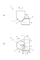
- FIG. 3 is an explanatory diagram of a chamfering operation for chamfering a corner portion 3 of the work 2.
- FIG. 4 is an explanatory diagram of the positional relationship between the chamfering cutter 1 and the corner portion 3 of the work 2 in the chamfering operation.
- FIG. 4A is a side view of the chamfering cutter 1 and the work 2 when viewed from a direction orthogonal to the axis L.
- FIG. 4B is an explanatory view when the contact portion between the chamfer cutter 1 and the work 2 is viewed from the axial direction X.
- FIG. 5 is an explanatory view when the positional relationship between the chamfering cutter 1 and the corner portion 3 of the work 2 is deviated.
- FIG. 4A is a side view of the chamfering cutter 1 and the work 2 when viewed from a direction orthogonal to the axis L.
- FIG. 4B is an explanatory view when the contact portion between the chamfer cutter 1 and the work
- FIG. 5A is a side view when the chamfering cutter 1 and the work 2 are viewed from a direction orthogonal to the axis L
- FIG. 5B is an axial direction of the contact portion between the chamfering cutter 1 and the work 2. It is explanatory drawing when viewed from X.
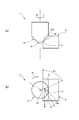
- FIG. 6 is an explanatory diagram of a chamfering operation of a chamfering cutter of a comparative example including an arc-shaped cutting edge.
- the chamfering cutter 1 When performing the chamfering operation, the chamfering cutter 1 is connected to the machine tool and rotated around the axis L in a predetermined rotation direction R. Then, the blade portion 11 is brought into contact with the corner portion 3 of the work 2, and the chamfer cutter 1 is moved in the moving direction M orthogonal to the axis L to form the chamfered surface 5.
- the ideal chamfered surface 5 is first set. Then, as shown in FIG. 4A, the chamfer cutter 1 is arranged so that the center 10a in the radial direction of the cutting edge 10 is positioned at the center in the width direction of the ideal chamfering surface 5. Then, the chamfer cutter 1 is moved in the moving direction M in a state where the center in the width direction of the ideal chamfered surface 5 and the center 10a in the radial direction of the cutting edge 10 are aligned with each other. As a result, the corner portion 3 of the work 2 is formed with a chamfered surface 5 that is inclined at the same angle as the angle at which the cutting edge 10 is inclined with respect to the axis L and extends in the moving direction M.
- the cutting edge 10 is linear in the rear R2 of the rotation direction R toward the outer peripheral side when viewed from the axial direction X.
- the extending inner cutting edge portion 16, the outer cutting edge portion 17 extending linearly in the front R1 in the rotation direction R toward the outer peripheral side on the radial outer side of the inner cutting edge portion 16, and the outer peripheral side of the inner cutting edge portion 16. It is composed of a bent cutting edge portion 18 that connects the end and the end on the inner peripheral side of the outer cutting edge portion 17.
- the inner cutting edge portion is as shown in FIG.
- the vector V1 of the cutting force applied to the corner portion 3 of the work 2 from 16 and the vector V2 of the cutting force applied to the corner portion 3 of the work 2 from the outer cutting edge portion 17 are in the width direction of the chamfered surface 5 formed by cutting. Head to the center. Further, the flow of chips due to cutting is directed to the bent cutting edge portion 18 between the inner cutting edge portion 16 and the outer cutting edge portion 17. As a result, it is possible to suppress the occurrence of Poisson burrs on the edges of the chamfered surface 5 formed by cutting.
- the inner cutting edge portion 16 when the cutting edge 10 is viewed from the axial direction X, the inner cutting edge portion 16 extending linearly in the rearward R2 in the rotation direction R toward the outer peripheral side and the inner cutting edge portion 16 and the inner cutting edge
- the outer cutting edge portion 17 extending linearly in the front R1 in the rotation direction R toward the outer peripheral side on the radial outer side of the portion 16, the outer peripheral side end of the inner cutting edge portion 16 and the inner peripheral side of the outer cutting edge portion 17 Since it is composed of a bending cutting edge portion 18 connecting to the end of the cutting edge, even if the positional relationship between the chamfering cutter 1 and the corner portion 3 of the work 2 deviates in the direction orthogonal to the moving direction M, the cutting edge 10 and The contact angle at which the work 2 comes into contact can be maintained.
- the position of the corner portion 3 of the work 2 chucked by the machine tool may shift in a direction orthogonal to the moving direction M of the chamfering cutter 1 due to a tolerance.
- the center 10a in the radial direction of the cutting edge 10 is aligned with the center in the width direction of the ideal chamfered surface 5 set in advance. I will not do it.
- the radial center 10a of the cutting edge 10 is deviated below the ideal chamfered surface 5 in the inclined direction from the state shown in FIG. That is, in the example shown in FIG. 5, the cutting edge 10 is in shallower contact with the corner portion 3 of the work 2 than in the state shown in FIG.
- the contact angle between the work 2 and the cutting edge 10 is maintained. That is, even when the cutting edge 10 makes shallow contact with the corner portion 3 of the work 2, as shown in FIGS. 4 and 5, the contact angle between the inner cutting edge portion 16 and the work 2 is the inner cutting edge.
- the portion 16 is maintained at an inclination angle ⁇ 1 that is inclined with respect to the radial direction. Therefore, the accuracy of chamfering (cutting) can be maintained, and the occurrence of Poisson burrs can be suppressed.
- the chamfer cutter 51 of the comparative example has an arc shape when the cutting edge 50 is viewed from the axial direction X. Further, although not shown, in the chamfering cutter 51 of the comparative example, the waste discharge groove 13 is provided in a spiral around the axis L.
- the chamfering cutter 51 of the comparative example has the same configuration as the chamfering cutter 1 of this example except for the shape of the cutting edge 50 and the shape of the waste discharge groove 13.
- the ideal chamfer surface 5 is first set as shown in FIG. 6A. Then, the chamfer cutter 51 is arranged so that the center 50a in the radial direction of the cutting edge 50 is located at the center of the ideal chamfered surface 5 in the width direction. Further, the chamfer cutter 51 is moved in the moving direction M in a state where the center in the width direction of the ideal chamfered surface 5 and the center 50a in the radial direction of the cutting edge 50 are aligned with each other. As a result, the corner portion 3 of the work 2 is formed with a chamfered surface 5 that is inclined at the same angle as the cutting edge 50 is inclined with respect to the axis L and extends in the moving direction M.
- the end portion 50b on the inner peripheral side of the cutting edge 50 is curved toward the rear R2 in the rotation direction R toward the outer peripheral side.
- the end portion 50c on the outer peripheral side of the cutting edge 50 is curved toward the outer peripheral side in the front R1 in the rotation direction R. Therefore, similarly to the chamfering cutter 1, the vector V1 of the cutting force applied to the corner portion 3 of the work 2 from the end portion 50b on the inner peripheral side of the cutting edge 50 and the cutting force are as in the case of the chamfering cutter 1 shown in FIG.
- the vector V2 of the cutting force applied to the corner portion 3 of the work 2 from the end portion 50c on the outer peripheral side of the blade 50 is directed toward the center of the chamfered surface 5 formed by cutting in the width direction. Further, the flow of chips due to cutting is directed to the bent cutting edge portion 18 between the inner cutting edge portion 16 and the outer cutting edge portion 17. Therefore, it is possible to suppress the occurrence of Poisson burrs on the edge of the chamfered surface 5 formed by cutting.
- the contact angle between the work 2 and the cutting edge 50 cannot be maintained. ..
- the cutting edge 50 makes shallow contact with the corner portion 3 of the work 2, and the radial center 50a of the cutting edge 50 is chamfered from the center of the ideal chamfered surface 5.
- the end portion 50b on the inner peripheral side of the cutting edge 50 does not come into contact with the work 2.
- the central portion 50d of the cutting edge 50 comes into contact with the work 2 instead of the end portion 50b on the inner peripheral side of the cutting edge 50.
- the contact angle at which the central portion 50d of the cutting edge 50 contacts the work 2 is the end portion 50b on the inner peripheral side of the cutting edge 50.
- the contact angle ( ⁇ 1 + ⁇ ) is deeper than the inclination angle ⁇ 1.
- the vector V1 of the cutting force applied from the central portion 50d of the cutting edge 50 to the corner portion 3 of the work 2 is when the end portion 50b on the inner peripheral side of the blade portion 11 is in contact with the corner portion 3 of the work 2. Compared to, it becomes larger.
- the direction of the vector V1 is toward the outside in the width direction of the chamfered surface 5 as compared with the case where the end portion 50b on the inner peripheral side of the blade portion 11 is in contact with the corner portion 3 of the work 2. Then, the flow of chips due to cutting goes downward in the inclined direction of the chamfered surface 5 formed by cutting.
- the chamfering cutter 51 of the comparative example when the positional relationship between the corner portion 3 of the work 2 and the chamfering cutter 51 deviates from the preset positional relationship, the chamfering (compared to the case where the chamfering cutter 1 is used) is performed. The accuracy of cutting) fluctuates. Further, when the chamfering cutter 51 of the comparative example is used, if the positional relationship between the corner portion 3 of the work 2 and the chamfering cutter 51 deviates from the preset positional relationship, poreson burrs are likely to occur.
- the first angle ⁇ 1 of the inner cutting edge portion 16 and the second angle ⁇ 2 of the outer cutting edge portion 17 are 25 ° or more and 45 ° or less.
- the effect of suppressing the occurrence of Poisson burr is remarkable.
- the first angle ⁇ 1 and the second angle ⁇ 2 are in such a range, it is omitted if the shape of the cutting edge 10 when viewed from the axial direction X opens 90 ° or more toward the front R1 in the rotation direction R. Since the shape is V-shaped, it is easy to form the cutting edge 10 on the blade portion 11.
- first angle ⁇ 1 of the inner cutting edge portion 16 and the second angle ⁇ 2 of the outer cutting edge portion 17 are 5 ° or more, the effect of suppressing the occurrence of Poisson burr can be exhibited. In other words, when the first angle ⁇ 1 and the second angle ⁇ 2 are smaller than 5 °, it becomes difficult to exhibit the effect of suppressing the occurrence of Poisson burr. Further, if the first angle ⁇ 1 of the inner cutting edge portion 16 and the second angle ⁇ 2 of the outer cutting edge portion 17 are set to 70 ° or less, it becomes easy to form the cutting edge 10 on the blade portion 11. In other words, when the first angle ⁇ 1 and the second angle ⁇ 2 are larger than 70 °, it becomes difficult to form the blade portion 11 on the blade portion 11.
- both the first angle ⁇ 1 and the second angle ⁇ 2 exceed 45 °
- both the first angle ⁇ 1 and the second angle ⁇ 2 provide the cutting edge 10 of 45 ° or less.
- the formation of the cutting edge 10 is not easy as compared with the above, the formation of the cutting edge 10 can be facilitated by providing the bent cutting edge portion 18 having a radius in the radial direction.
- the first angle ⁇ 1 in which the inner cutting edge portion 16 is inclined rearward X2 with respect to the radial direction is the second angle ⁇ 2 in which the outer cutting edge portion 17 is inclined forward X1 with respect to the radial direction. Greater than. Therefore, the occurrence of Poisson burrs can be suppressed at both end edges of the chamfered surface 5 in the width direction. That is, when the chamfer cutter 1 is rotated, the peripheral speed of the outer cutting edge portion 17 located on the outer peripheral side is faster than the peripheral speed of the inner cutting edge portion 16. Therefore, the cutting force of the outer cutting edge portion 17 is higher than the cutting force of the inner cutting edge portion 16.
- one edge in the width direction of the chamfered surface 5 chamfered by the outer cutting edge portion 17 is one edge in the width direction of the chamfered surface 5 chamfered by the inner cutting edge portion 16.
- the cutting force of the inner cutting edge portion 16 is lower than the cutting force of the outer cutting edge portion 17. Therefore, in the work 2, the other edge in the width direction of the chamfered surface 5 chamfered by the inner cutting edge portion 16 is one edge in the width direction of the chamfered surface 5 chamfered by the outer cutting edge portion 17. Compared with, there is a problem that Poisson burr is likely to occur.
- the first angle ⁇ 1 of the inner cutting edge portion 16 is made larger than the second angle ⁇ 2 of the outer cutting edge portion 17.
- the vector V1 of the cutting force applied to the work 2 from the inner cutting edge portion 16 is larger than the vector V2 of the cutting force applied to the work 2 from the outer cutting edge portion 17 in the width direction of the chamfered surface 5 formed by cutting. It can be directed to the center. Therefore, it is possible to suppress the occurrence of Poisson burrs even at the edge of the chamfered surface 5 formed by cutting the inner cutting edge portion 16.
- the difference between the first angle ⁇ 1 and the second angle ⁇ 2 is 2 ° or more and 10 ° or less. Therefore, a virtual circle that passes through the inflection point P of the radius of the bent cutting edge portion 18 located between the inner cutting edge portion 16 and the outer cutting edge portion 17 in the radial direction and the center 50a in the radial direction of the cutting edge 50. It is easy to provide it at a position close to C.
- the inflection point P is provided at a position close to the virtual circle C, the ideal chamfered surface is provided even if the position of the corner portion 3 of the work 2 deviates in the direction orthogonal to the moving direction M of the chamfering cutter 1. Both end edges of 55 in the width direction can be cut by the inner cutting edge portion 16 and the outer cutting edge portion 17. Therefore, the occurrence of Poisson Bali can be suppressed.
- the bent cutting edge portion 18 connecting the inner cutting edge portion 16 and the outer cutting edge portion 17 is provided with a radius, and the inflection point P of the radius of the bending cutting edge portion 18 is a virtual circle C. It is located on the inner circumference side. Therefore, it is easy to make the first angle ⁇ 1 of the inner cutting edge portion 16 larger than the second angle ⁇ 2 of the outer cutting edge portion 17.
- the shapes of the inner cutting edge portion 16, the outer cutting edge portion 17, and the bending cutting edge portion 18 may be set so that the inflection point P is located on the virtual circle C.
- the bending cutting edge portion 18 has an arc shape having a radius when viewed from the axial direction X, but the bending cutting edge portion 18 is linear with the inner cutting edge portion 16 extending linearly. It can also be an intersection where the outer cutting edge portion 17 extending to is intersected. That is, the cutting edge 10 may have a V-shape in which the inner cutting edge portion 16 and the outer cutting edge portion 17 intersect at an acute angle at a predetermined angle in the bending cutting edge portion 18.
- the waste discharge groove 13 extends linearly in the axial direction X. Therefore, the chamfer cutter 51 can be easily manufactured as compared with the case where the waste discharge groove 13 is provided in a spiral around the axis L.
- the chamfering cutter 51 is moved in the direction intersecting the axis L to perform the chamfering operation.
- the blade portion 11 is inserted into the hole formed in the work 2 to form a hole in the work 2. Even when chamfering the opening edge, the occurrence of Poisson burrs can be suppressed.
- the blade portion 11 is provided with the flat portion 15 at the center of the front end, but the flat portion 15 may not be provided. That is, the blade portion 11 may include a conical portion that tapers toward the front X1 instead of the flat portion 15. Further, the conical portion may be provided with a second cutting edge different from the above-mentioned cutting edge 10.
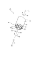
- FIG. 7 is a partial perspective view of the vicinity of the blade portion 11 of the chamfering cutter of the modified example. Since the chamfering cutter 1A of this example has a configuration corresponding to the above-mentioned chamfering cutter 1, the same reference numerals are given to the corresponding configurations, and the description thereof will be omitted.
- the chamfer cutter 1A includes a truncated cone-shaped blade portion 11 at the front X1 of the shaft portion 12. That is, the blade portion 11 includes a flat portion 15 at the center of the front end of the blade portion 11. Further, the blade portion 11 includes a tapered outer peripheral surface 31 whose diameter increases from the flat portion 15 toward the rear X2.
- an inner rib 32 extending linearly in the rear R2 in the rotation direction R toward the outer peripheral side is provided.
- eight inner ribs 32 are provided at equal intervals.
- the cross-sectional shape of the inner rib 32 is rectangular.
- the tapered outer peripheral surface 31 is provided with an outer rib 33 extending linearly in the front R1 in the rotation direction R toward the outer peripheral side on the radial outer side of each inner rib 32.
- Eight outer ribs 33 are provided at equal intervals.
- the cross-sectional shape of the outer rib 33 is rectangular.
- the outer peripheral end portion of the inner rib 32 and the inner peripheral end portion of the outer rib 33 overlap when viewed from the circumferential direction. That is, the outer peripheral end portion of the inner rib 32 protrudes toward the outer peripheral side from the inner peripheral end of the outer rib 33.
- An inner cutting edge portion 16 constituting the cutting edge 10 is provided at a corner portion located on the outer peripheral side of the inner rib 32 at the front R1 in the rotation direction R.
- An outer cutting edge portion 17 constituting the cutting edge 10 is provided at a corner portion located on the outer peripheral side of the outer rib 33 at the front R1 in the rotation direction R.
- the inner cutting edge portion 16 extends linearly toward the outer peripheral side in the rear R2 in the rotation direction R.
- the outer cutting edge portion 17 extends linearly in the front R1 in the rotation direction R toward the outer peripheral side on the radial outer side of the inner cutting edge portion 16.
- the outer peripheral end portion of the inner cutting edge portion 16 and the inner peripheral end portion of the outer cutting edge portion 17 overlap when viewed from the circumferential direction. That is, the outer peripheral end portion of the inner cutting edge portion 16 projects toward the outer peripheral side from the inner peripheral end portion of the outer cutting edge portion 17.
- the chamfering cutter 1A of this example can also obtain the same action and effect as the above chamfering cutter 1.
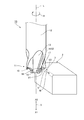
- FIG. 8 is an external view of the chamfering cutter of the second embodiment.
- FIG. 9 is a plan view of the chamfer cutter of FIG. 8 as viewed from the side of the blade portion. Since the chamfering cutter 1B of the second embodiment has a configuration corresponding to the chamfering cutter 1 described above, the corresponding configuration will be described with the same reference numerals.
- the chamfering cutter 1B includes a blade portion 11 having a cutting blade 10 and a shaft portion 12 coaxial with the blade portion 11.
- the cutting edge 10 is provided along the radial outer edge of the blade portion 11.
- the shaft portion 12 has a cylindrical shape.
- the shaft portion 12 is connected to the head of the machine tool.
- the chamfering cutter 1B moves around the axis L of the shaft portion 12 in a direction intersecting the axis L while rotating in a predetermined rotation direction R to chamfer the corner portion 3 of the work 2.
- the blade portion 11 is continuously provided on the front X1 of the shaft portion 12.
- the blade portion 11 includes a flat portion 15 at the center of the front end. Further, the blade portion 11 is a curved portion of the blade portion whose radial outer edge is curved toward the outer peripheral side toward the second direction X2 (the side of the shaft portion 12) when viewed from a direction orthogonal to the axis L. 11a is provided. As a result, the cutting edge 10 provided along the radial outer edge of the blade portion 11 is second from the outer peripheral end of the flat portion 15 when viewed from a direction orthogonal to the axis of the shaft portion 12.
- a second portion 63 which extends linearly in the second direction X2 from the outer peripheral side end of the above, is provided.
- the end of the first portion 61 in the second direction X2 and the curved portion 62 are continuous without a step. Further, the curved portion 62 and the end on the inner peripheral side of the second portion 63 are continuous without a step.
- the blade portion 11 includes a waste discharge groove 13 adjacent to the cutting blade 10.
- the waste discharge groove 13 is located in front R1 in the rotation direction R with respect to the cutting edge 10.
- the blade portion 11 includes four cutting blades 10 at equal angle intervals around the axis L. Therefore, the blade portion 11 is provided with four waste discharge grooves 13 at equal angular intervals around the axis L.
- Each waste discharge groove 13 opens outward in the radial direction.
- the opening edge of each waste discharge groove 13 in the blade portion 11 includes a front opening edge portion 13a located at the front R1 in the rotation direction R and a rear opening edge portion 13b located behind the rotation direction R.
- the cutting edge 10 is provided on the rear opening edge portion 13b.
- each cutting edge 10 has an inner cutting edge portion 16 extending linearly in the rearward R2 in the rotation direction R toward the outer peripheral side and an inner cutting edge portion 16 when viewed from the axial direction X.
- the outer cutting edge portion 17 extending linearly in the front R1 in the rotation direction R toward the outer peripheral side on the outer side in the radial direction, the outer peripheral side end of the inner cutting edge portion 16, and the inner peripheral side end of the outer cutting edge portion 17. It is composed of a bending cutting edge portion 18 located between and.
- the bent cutting edge portion 18 is a portion that connects the outer peripheral end of the inner cutting edge portion 16 and the inner peripheral end of the outer cutting edge portion 17.
- the bent cutting edge portion 18 is curved.
- the bending cutting edge portion 18 is recessed in the rear R2 in the rotation direction R.
- the inner cutting edge portion 16 is provided at the core height by the dimension H1.
- the inner cutting edge portion 16 has a rotation direction of only the dimension H1 when a virtual surface S1 parallel to the inner cutting edge portion 16 and including the axis L is defined behind R2 of the rotation direction R of the inner cutting edge portion 16. It is located in front of R R1.
- the bent cutting edge portion 18 is provided on the curved portion 62. In other words, the bent cutting edge portion 18 is provided so as to completely overlap the curved portion 62, or is provided inside the curved portion 62. Therefore, the bent cutting edge portion 18 is located between the first portion 61 and the second direction X2 in the axial direction X when viewed from a direction orthogonal to the axis.
- the bent cutting edge portion 18 and the curved portion 62 completely overlap each other. Therefore, in the cutting edge 10, a portion (curved portion) that curves toward the outer peripheral side toward the second direction X2 when viewed from a direction orthogonal to the axis L is behind the rotation direction R when viewed from the axis direction X. It is curved to R2. Further, the inner cutting edge portion 16 and the first portion 61 completely overlap each other, and the outer cutting edge portion 17 and the second portion 63 completely overlap each other.
- a portion (inner cutting edge portion 16) extending linearly in the rear R2 of the rotation direction R toward the outer peripheral side when viewed from a direction orthogonal to the axis L is viewed from the axis direction X. In the case, it extends linearly toward the outer peripheral side toward the second direction X2. Further, in the cutting edge 10, a portion (outer cutting edge portion 17) extending linearly in the front R1 of the rotation direction R toward the outer peripheral side when viewed from a direction orthogonal to the axis L is viewed from the axis direction X. In the case, it extends linearly in the second direction X2 toward the outer peripheral side.
- the inner peripheral side end 16a of the inner cutting edge portion 16 and the outer peripheral side end 17a of the outer cutting edge portion 17 are such that the outer peripheral side end 17a of the outer cutting edge portion 17 is in the rotation direction R. It is located on the front R1.
- the first angle ⁇ 1 in which the inner cutting edge portion 16 is inclined rearward X2 with respect to the radial direction and the second angle ⁇ 2 in which the outer cutting edge portion 17 is inclined forward X1 with respect to the radial direction are 5 ° or more, respectively. , 85 ° or less.
- the first angle ⁇ 1 in which the inner cutting edge portion 16 is inclined is larger than the second angle ⁇ 2 in which the outer cutting edge portion 17 is inclined.
- the first angle ⁇ 1 is 79 ° and the second angle ⁇ 2 is 19 °.
- the difference between the first angle ⁇ 1 and the second angle ⁇ 2 is 60 °.
- the curved inflection point 18a of the bent cutting edge portion 18 is located on the inner peripheral side of the virtual circle C1 passing through the center 10a of the cutting edge 10 in the radial direction.
- the inner peripheral side end 16a of the inner cutting edge portion 16 and the outer peripheral side end 17a of the outer cutting edge portion 17 may be at the same angular position around the axis L.
- the effect of suppressing the occurrence of pore son burr can be exhibited.
- the first angle ⁇ 1 and the second angle ⁇ 2 are smaller than 5 °, it becomes difficult to exhibit the effect of suppressing the occurrence of Poisson burr.
- the first angle ⁇ 1 of the inner cutting edge portion 16 and the second angle ⁇ 2 of the outer cutting edge portion 17 are set to 85 ° or less, it becomes easy to form the cutting edge 10 on the blade portion 11.
- the inner cutting edge portion 16 and the outer cutting edge portion 17 are not provided on the same plane as the cutting edge 10 of the chamfering cutter 1 of the first embodiment.
- the bent cutting edge portion 18 and the curved portion 62 overlap each other, and the radius of the bent cutting edge portion 18 is larger than that of the chamfering cutter 1 of the first embodiment. From this point as well, in this example, it is easy to provide the cutting edge 10 on the blade portion 11 even when the first angle ⁇ 1 and the second angle ⁇ 2 exceed 70 °.
- FIG. 10 is an explanatory diagram of a chamfering operation in which the corner portion 3 of the work 2 is chamfered by the chamfering cutter 1B.
- the chamfering cutter 1B is connected to the machine tool to rotate around the axis L in a predetermined rotation direction R.
- the curved portion 62 of the blade portion 11 is brought into contact with the corner portion 3 of the work 2, and the chamfer cutter 1B is moved in the moving direction M orthogonal to the axis L to form the chamfered surface 5.
- a chamfered surface 5 extending in the moving direction M in a curved shape obtained by transferring the curved portion 62 is formed on the corner portion 3 of the work 2.
- the cutting edge 10 is a straight line in the rearward R2 of the rotation direction R toward the outer peripheral side when viewed from the axial direction X.
- the inner cutting edge portion 16 extending in a shape
- the outer cutting edge portion 17 extending linearly in the front R1 in the rotation direction R toward the outer peripheral side on the radial outer side of the inner cutting edge portion 16, and the outer peripheral edge of the inner cutting edge portion 16. It is composed of a bent cutting edge portion 18 that connects a side end and an inner peripheral side end of the outer cutting edge portion 17. Therefore, as shown in FIG.
- the vector V2 of the cutting force applied to the corner portion 3 of the work 2 from the side end portion and the outer cutting edge portion 17 tends toward the center of the chamfered surface 5 formed by cutting in the width direction. Further, the flow of chips due to cutting is directed to the bent cutting edge portion 18 between the inner cutting edge portion 16 and the outer cutting edge portion 17. As a result, it is possible to suppress the occurrence of Poisson burrs on the edges of the chamfered surface 5 formed by cutting.
- the cutting edge 10 has an inner cutting edge portion 16 extending linearly in the rear R2 of the rotation direction R toward the outer peripheral side and an inner cutting edge when viewed from the axial direction X.
- the outer cutting edge portion 17 extending linearly in the front R1 in the rotation direction R toward the outer peripheral side on the radial outer side of the portion 16, the outer peripheral side end of the inner cutting edge portion 16 and the inner peripheral side of the outer cutting edge portion 17 It is composed of a bent cutting edge portion 18 that connects to the end of the blade. Therefore, as in the case shown in FIG. 5B, even if the positional relationship between the chamfering cutter 1B and the corner portion 3 of the work 2 deviates in the direction orthogonal to the moving direction M, the cutting edge 10 and the work 2 Can maintain the contact angle of contact.
- the first angle ⁇ 1 in which the inner cutting edge portion 16 is inclined rearward X2 with respect to the radial direction is the second angle ⁇ 2 in which the outer cutting edge portion 17 is inclined forward X1 with respect to the radial direction. Greater than. Therefore, even if the cutting force of the inner cutting edge portion 16 is smaller than the cutting force of the outer cutting edge portion 17 due to the peripheral speed, the vector V1 of the cutting force applied to the work 2 from the inner cutting edge portion 16 can be obtained. , The cutting force applied to the work 2 from the outer cutting edge portion 17 can be directed toward the center of the chamfered surface 5 in the width direction rather than the vector V2. Therefore, it is possible to suppress the occurrence of poreson burrs even at the edge of the chamfered surface 5 formed by cutting the inner cutting edge portion 16.
Abstract
Description
前記刃部を前記軸線方向から見た場合に、前記切刃は、外周側に向かって前記回転方向の後方に直線状に延びる内側切刃部分と、前記内側切刃部分の径方向外側で前記外周側に向かって前記回転方向の前方に直線状に延びる外側切刃部分と、を備えることを特徴とする。 In order to solve the above problems, the present invention has a blade portion provided with a cutting blade and a shaft portion coaxial with the blade portion, and the cutting blade is along the radial edge of the blade portion. In a chamfering cutter that is provided and rotates around the axis in a predetermined rotation direction to chamfer the corners of the work.
When the blade portion is viewed from the axial direction, the cutting blade has an inner cutting edge portion that extends linearly rearward in the rotational direction toward the outer peripheral side and a radial outer side of the inner cutting edge portion. It is characterized by including an outer cutting edge portion that extends linearly forward in the rotational direction toward the outer peripheral side.
図1は本発明を適用した面取りカッターの外観図である。図2は面取りカッターを刃部の側から見た場合の平面図である。本例の面取りカッター1は、ワーク2の角部3を面取りするための工具である。ワーク2は、例えば、金属製の鋳造品である。面取りカッター1は、不図示の工作機械のヘッドに連結されて使用される。面取りカッター1は、超硬合金製である。 (Example 1)
FIG. 1 is an external view of a chamfering cutter to which the present invention is applied. FIG. 2 is a plan view of the chamfer cutter when viewed from the side of the blade portion. The
図3は、ワーク2の角部3を面取りする面取り動作の説明図である。図4は、面取り動作における面取りカッター1とワーク2の角部3との位置関係の説明図である。図4(a)は、面取りカッター1とワーク2とを軸線Lと直交する方向から見た場合の側面図である。図4(b)は面取りカッター1とワーク2との接触部分を軸線方向Xから見た場合の説明図である。図5は、面取りカッター1とワーク2の角部3との位置関係がズレた場合の説明図である。図5(a)は、面取りカッター1とワーク2とを軸線Lと直交する方向から見た場合の側面図である、図5(b)は面取りカッター1とワーク2との接触部分を軸線方向Xから見た場合の説明図である。図6は、円弧形状の切刃を備える比較例の面取りカッターの面取り動作の説明図である。 (Chamfering operation)
FIG. 3 is an explanatory diagram of a chamfering operation for chamfering a
また、上記の例では、刃部11は前端の中心に平坦部15を備えているが、平坦部15を備えていなくてもい。すなわち、刃部11は、平坦部15に替えて、前方X1に向かって先細りとなる円錐部を備えていてもよい。また、この円錐部に、上記の切刃10とは別の第2の切刃を備えてもよい。 (Modification example)
Further, in the above example, the
図8は、実施例2の面取りカッターの外観図である。図9は、図8の面取りカッターを刃部の側から見た場合の平面図である。なお、実施例2の面取りカッター1Bは、上記の面取りカッター1と対応する構成を備えるので、対応する構成には同一の符号を付して説明する。 (Example 2)
FIG. 8 is an external view of the chamfering cutter of the second embodiment. FIG. 9 is a plan view of the chamfer cutter of FIG. 8 as viewed from the side of the blade portion. Since the
図10は、面取りカッター1Bによってワーク2の角部3を面取りする面取り動作の説明図である。面取り動作を行う際には、面取りカッター1Bを工作機械に接続して、軸線L回りを所定の回転方向Rに回転させる。そして、ワーク2の角部3に刃部11の湾曲部分62を接触させ、面取りカッター1Bを軸線Lと直交する移動方向Mに移動させて、面取り面5を形成する。これにより、ワーク2の角部3には、湾曲部分62を転写した湾曲形状で移動方向Mに延びる面取り面5が形成される。 (Chamfering operation)
FIG. 10 is an explanatory diagram of a chamfering operation in which the
Claims (15)
- 切刃を備える刃部と、前記刃部と同軸の軸部と、を有し、前記切刃が前記刃部の径方向の端縁に沿って設けられており、前記軸部の軸線回りを所定の回転方向に回転してワークの角部の面取りを行う面取りカッターにおいて、
前記刃部を前記軸線方向から見た場合に、前記切刃は、外周側に向かって前記回転方向の後方に直線状に延びる内側切刃部分と、前記内側切刃部分の径方向外側で前記外周側に向かって前記回転方向の前方に直線状に延びる外側切刃部分と、を備えることを特徴とする面取りカッター。 It has a blade portion provided with a cutting blade and a shaft portion coaxial with the blade portion, and the cutting blade is provided along the radial edge of the blade portion so as to rotate around the axis of the shaft portion. In a chamfering cutter that chamfers the corners of a workpiece by rotating in a predetermined rotation direction.
When the blade portion is viewed from the axial direction, the cutting blade has an inner cutting edge portion that extends linearly rearward in the rotational direction toward the outer peripheral side and a radial outer side of the inner cutting edge portion. A chamfering cutter including an outer cutting edge portion that extends linearly forward in the direction of rotation toward the outer peripheral side. - 前記切刃は、前記軸部の軸線と直交する方向から見た場合に、外周側に向かって前記軸部の側に直線状に傾斜していることを特徴とする請求項1に記載の面取りカッター。 The chamfer according to claim 1, wherein the cutting edge is linearly inclined toward the outer peripheral side toward the outer peripheral side when viewed from a direction orthogonal to the axis of the shaft portion. cutter.
- 前記切刃は、前記内側切刃部分の外周側の端と前記外側切刃部分の内周側の端との間に位置する屈曲切刃部分を備えることを特徴とする請求項2に記載の面取りカッター。 The second aspect of the present invention, wherein the cutting edge includes a bending cutting edge portion located between an outer peripheral end of the inner cutting edge portion and an inner peripheral end of the outer cutting edge portion. Chamfering cutter.
- 前記刃部は、前記切刃に前記回転方向の前方で隣り合う屑排出溝を備え、
前記屑排出溝は、前記軸線方向に直線状に延びることを特徴とする請求項2に記載の面取りカッター。 The blade portion is provided with a waste discharge groove adjacent to the cutting blade in the front in the rotation direction.
The chamfering cutter according to claim 2, wherein the waste discharge groove extends linearly in the axial direction. - 前記内側切刃部分の内周側の端と、前記外側切刃部分の外周側の端とは、前記軸線回りの同一の角度位置にあることを特徴とする請求項2に記載の面取りカッター。 The chamfer cutter according to claim 2, wherein the end on the inner peripheral side of the inner cutting edge portion and the end on the outer peripheral side of the outer cutting edge portion are at the same angle position around the axis.
- 前記内側切刃部分が径方向に対して前記後方に傾斜する第1角度、および前記外側切刃部分が径方向に対して前記前方に傾斜する第2角度は、それぞれ、5°以上、70°以下であることを特徴とする請求項2に記載の面取りカッター。 The first angle at which the inner cutting edge portion is inclined rearward with respect to the radial direction and the second angle at which the outer cutting edge portion is inclined forward with respect to the radial direction are 5 ° or more and 70 °, respectively. The chamfering cutter according to claim 2, wherein the chamfering cutter is as follows.
- 前記第1角度は、前記第2角度よりも大きいことを特徴とする請求項6に記載の面取りカッター。 The chamfering cutter according to claim 6, wherein the first angle is larger than the second angle.
- 前記第1角度と前記第2角度との差は、2°以上、10°以下であることを特徴とする請求項7に記載の面取りカッター。 The chamfering cutter according to claim 7, wherein the difference between the first angle and the second angle is 2 ° or more and 10 ° or less.
- 前記刃部を前記軸線と直交する方向から見た場合に、前記切刃は、前記軸線に対して45°傾斜していることを特徴とする請求項2に記載の面取りカッター。 The chamfering cutter according to claim 2, wherein the cutting edge is inclined by 45 ° with respect to the axis when the blade is viewed from a direction orthogonal to the axis.
- 前記切刃は、前記内側切刃部分の外周側の端部分と前記外側切刃部分の内周側の端部分とが、周方向から見た場合に重なっていることを特徴とする請求項1に記載の面取りカッター。 Claim 1 is characterized in that the outer peripheral end portion of the inner cutting edge portion and the inner peripheral end portion of the outer cutting edge portion overlap when viewed from the circumferential direction. Chamfering cutter described in.
- 前記切刃は、径方向で前記内側切刃部分の外周側の端と前記外側切刃部分の内周側の端との間に位置して当該前記内側切刃部分と当該外側切刃部分とを接続する屈曲切刃部分を備えるとともに、前記軸部の軸線と直交する方向から見た場合に、前記軸部の側に向かって外周側に湾曲する湾曲部分を備え、
前記屈曲切刃部分は、前記湾曲部分に設けられていることを特徴とする請求項2に記載の面取りカッター。 The cutting edge is located between the outer peripheral end of the inner cutting edge portion and the inner peripheral end of the outer cutting edge portion in the radial direction, and the inner cutting edge portion and the outer cutting edge portion. It is provided with a bent cutting edge portion for connecting the shaft portion, and also has a curved portion that curves toward the outer peripheral side toward the shaft portion side when viewed from a direction orthogonal to the axis of the shaft portion.
The chamfering cutter according to claim 2, wherein the bent cutting edge portion is provided on the curved portion. - 前記切刃は、前記軸部の軸線と直交する方向から見た場合に、前記軸部の側に向かって外周側に直線状に延びる第1部分と、前記第1部分の前記軸部の側の端から湾曲する前記湾曲部分と、前記湾曲部分の外周側の端から外周側に向かって前記軸部の側に直線状に延びる第2部分と、を備えることを特徴とする請求項11に記載の面取りカッター。 The cutting edge has a first portion that extends linearly toward the outer peripheral side toward the side of the shaft portion when viewed from a direction orthogonal to the axis of the shaft portion, and a side of the shaft portion of the first portion. 11. The eleventh aspect of the present invention is characterized in that the curved portion curved from the end of the curved portion and the second portion linearly extending from the outer peripheral side end of the curved portion toward the outer peripheral side toward the shaft portion. The described chamfer cutter.
- 前記内側切刃部分が径方向に対して前記後方に傾斜する第1角度、および前記外側切刃部分が径方向に対して前記前方に傾斜する第2角度は、それぞれ、5°以上、85°以下であることを特徴とする請求項11に記載の面取りカッター。 The first angle at which the inner cutting edge portion is inclined rearward with respect to the radial direction and the second angle at which the outer cutting edge portion is inclined forward with respect to the radial direction are 5 ° or more and 85 °, respectively. The chamfering cutter according to claim 11, wherein the chamfering cutter is as follows.
- 前記第1角度は、前記第2角度よりも大きいことを特徴とする請求項13に記載の面取りカッター。 The chamfering cutter according to claim 13, wherein the first angle is larger than the second angle.
- 請求項1に記載の面取りカッターを、前記軸線回りに回転させながらワークの角部に接触させて、前記軸線と交差する方向に移動させることを特徴とするワークの面取り方法。 A method for chamfering a work, wherein the chamfering cutter according to claim 1 is rotated around the axis and brought into contact with a corner of the work to move in a direction intersecting the axis.
Priority Applications (8)
| Application Number | Priority Date | Filing Date | Title |
|---|---|---|---|
| MX2022004094A MX2022004094A (en) | 2019-11-06 | 2020-05-08 | Beveling cutter and method for beveling workpiece. |
| CA3154182A CA3154182A1 (en) | 2019-11-06 | 2020-05-08 | Chamfering cutter and method of chamfering workpiece |
| JP2021554811A JPWO2021090525A1 (en) | 2019-11-06 | 2020-05-08 | |
| CN202080077339.5A CN114641362A (en) | 2019-11-06 | 2020-05-08 | Chamfering tool and chamfering method for workpiece |
| EP20883866.4A EP4056305A4 (en) | 2019-11-06 | 2020-05-08 | Beveling cutter and method for beveling workpiece |
| KR1020227015194A KR20220090519A (en) | 2019-11-06 | 2020-05-08 | Chamfering cutter and chamfering method of workpiece |
| US17/771,000 US20220402054A1 (en) | 2019-11-06 | 2020-05-08 | Chamfering cutter and method of chamfering workpiece |
| TW109130717A TW202126410A (en) | 2019-11-06 | 2020-09-08 | Beveling cutter and method for beveling workpiece |
Applications Claiming Priority (2)
| Application Number | Priority Date | Filing Date | Title |
|---|---|---|---|
| JP2019-201173 | 2019-11-06 | ||
| JP2019201173A JP6714248B1 (en) | 2019-11-06 | 2019-11-06 | Chamfering cutter and chamfering method for work |
Publications (1)
| Publication Number | Publication Date |
|---|---|
| WO2021090525A1 true WO2021090525A1 (en) | 2021-05-14 |
Family
ID=71103918
Family Applications (1)
| Application Number | Title | Priority Date | Filing Date |
|---|---|---|---|
| PCT/JP2020/018620 WO2021090525A1 (en) | 2019-11-06 | 2020-05-08 | Beveling cutter and method for beveling workpiece |
Country Status (9)
| Country | Link |
|---|---|
| US (1) | US20220402054A1 (en) |
| EP (1) | EP4056305A4 (en) |
| JP (2) | JP6714248B1 (en) |
| KR (1) | KR20220090519A (en) |
| CN (1) | CN114641362A (en) |
| CA (1) | CA3154182A1 (en) |
| MX (1) | MX2022004094A (en) |
| TW (1) | TW202126410A (en) |
| WO (1) | WO2021090525A1 (en) |
Cited By (2)
| Publication number | Priority date | Publication date | Assignee | Title |
|---|---|---|---|---|
| JP7071778B1 (en) * | 2022-01-14 | 2022-05-19 | 株式会社ジーベックテクノロジー | Deburring tool and deburring method |
| DE102021128197A1 (en) | 2021-10-28 | 2023-05-04 | Andreas Vratny | Spiralized deburrer |
Citations (5)
| Publication number | Priority date | Publication date | Assignee | Title |
|---|---|---|---|---|
| JP2000326130A (en) | 1999-05-18 | 2000-11-28 | Fujii Seisakusho:Kk | Chamfering cutter |
| JP3111276U (en) * | 2005-04-11 | 2005-07-14 | 株式会社デッケル・グラインダー ジャパン | Chamfering end mill |
| US20080050191A1 (en) * | 2006-08-25 | 2008-02-28 | Catlin Bryan L | Chamfer tool |
| JP3156158U (en) * | 2009-10-05 | 2009-12-17 | 株式会社ヘリックツール | Strong twist corner rounding cutter |
| JP2015521959A (en) * | 2012-07-04 | 2015-08-03 | ホフマン,ヤン,エンノ | Chamfering / Beveling Tool-Router Head for Metal |
Family Cites Families (11)
| Publication number | Priority date | Publication date | Assignee | Title |
|---|---|---|---|---|
| JPS5813917U (en) * | 1981-07-15 | 1983-01-28 | 株式会社日本工具製作所 | compound cutting tools |
| JPH0718488Y2 (en) * | 1990-11-14 | 1995-05-01 | 株式会社日進工具製作所 | Ball end mill |
| US5115697A (en) * | 1991-08-16 | 1992-05-26 | Smith International, Inc. | Diamond rotary cutter flute geometry |
| JPH0639634A (en) * | 1992-04-24 | 1994-02-15 | Takeo Sakakura | Cutter for corner processing and corner processing tool using this cutter |
| JP4608285B2 (en) * | 2004-11-05 | 2011-01-12 | 新庄金属工業株式会社 | Cutting method using rotary cutting tool |
| US20090010728A1 (en) * | 2006-02-23 | 2009-01-08 | National University Corporation Tokyo University Of Argriculture And Technology | Axial Asymmetric Edge Drill |
| JP2007260843A (en) * | 2006-03-29 | 2007-10-11 | Mitsubishi Materials Corp | Drill |
| IL174775A (en) * | 2006-04-04 | 2013-06-27 | Hanita Metal Works Ltd | Face milling cutter |
| US20090041554A1 (en) * | 2007-08-08 | 2009-02-12 | Hsu Hsiu-Kwei Liu | Chamfer drill |
| JP5470796B2 (en) * | 2008-10-06 | 2014-04-16 | 三菱マテリアル株式会社 | Overall cutter |
| WO2018092351A1 (en) * | 2016-11-15 | 2018-05-24 | 住友電工ハードメタル株式会社 | Cutting tool and cutting method |
-
2019
- 2019-11-06 JP JP2019201173A patent/JP6714248B1/en active Active
-
2020
- 2020-05-08 CN CN202080077339.5A patent/CN114641362A/en active Pending
- 2020-05-08 CA CA3154182A patent/CA3154182A1/en active Pending
- 2020-05-08 EP EP20883866.4A patent/EP4056305A4/en active Pending
- 2020-05-08 WO PCT/JP2020/018620 patent/WO2021090525A1/en unknown
- 2020-05-08 US US17/771,000 patent/US20220402054A1/en active Pending
- 2020-05-08 KR KR1020227015194A patent/KR20220090519A/en active Search and Examination
- 2020-05-08 JP JP2021554811A patent/JPWO2021090525A1/ja active Pending
- 2020-05-08 MX MX2022004094A patent/MX2022004094A/en unknown
- 2020-09-08 TW TW109130717A patent/TW202126410A/en unknown
Patent Citations (5)
| Publication number | Priority date | Publication date | Assignee | Title |
|---|---|---|---|---|
| JP2000326130A (en) | 1999-05-18 | 2000-11-28 | Fujii Seisakusho:Kk | Chamfering cutter |
| JP3111276U (en) * | 2005-04-11 | 2005-07-14 | 株式会社デッケル・グラインダー ジャパン | Chamfering end mill |
| US20080050191A1 (en) * | 2006-08-25 | 2008-02-28 | Catlin Bryan L | Chamfer tool |
| JP3156158U (en) * | 2009-10-05 | 2009-12-17 | 株式会社ヘリックツール | Strong twist corner rounding cutter |
| JP2015521959A (en) * | 2012-07-04 | 2015-08-03 | ホフマン,ヤン,エンノ | Chamfering / Beveling Tool-Router Head for Metal |
Non-Patent Citations (1)
| Title |
|---|
| See also references of EP4056305A4 |
Cited By (2)
| Publication number | Priority date | Publication date | Assignee | Title |
|---|---|---|---|---|
| DE102021128197A1 (en) | 2021-10-28 | 2023-05-04 | Andreas Vratny | Spiralized deburrer |
| JP7071778B1 (en) * | 2022-01-14 | 2022-05-19 | 株式会社ジーベックテクノロジー | Deburring tool and deburring method |
Also Published As
| Publication number | Publication date |
|---|---|
| CN114641362A (en) | 2022-06-17 |
| CA3154182A1 (en) | 2021-05-14 |
| EP4056305A4 (en) | 2023-12-06 |
| KR20220090519A (en) | 2022-06-29 |
| JPWO2021090525A1 (en) | 2021-05-14 |
| JP2021074798A (en) | 2021-05-20 |
| TW202126410A (en) | 2021-07-16 |
| JP6714248B1 (en) | 2020-06-24 |
| EP4056305A1 (en) | 2022-09-14 |
| MX2022004094A (en) | 2022-04-26 |
| US20220402054A1 (en) | 2022-12-22 |
Similar Documents
| Publication | Publication Date | Title |
|---|---|---|
| KR101516826B1 (en) | Insert for drill and insert drill | |
| JP5555691B2 (en) | drill | |
| WO2021090525A1 (en) | Beveling cutter and method for beveling workpiece | |
| KR101236041B1 (en) | Throw-away cutting rotary tool | |
| JP4902127B2 (en) | Chamfering cutter | |
| JP2010234462A (en) | End mill | |
| JP4677722B2 (en) | 3-flute ball end mill | |
| US7441991B2 (en) | Chamfering tool | |
| JP7071778B1 (en) | Deburring tool and deburring method | |
| JP2007015025A (en) | Taper neck end mill | |
| JP5958614B2 (en) | Ball end mill | |
| JP2011056608A (en) | Square end mill | |
| JP5633395B2 (en) | Cutting insert and cutting edge changeable cutting tool | |
| JP7423965B2 (en) | Drill | |
| JP7400311B2 (en) | Drill | |
| JP2006015419A (en) | Ball end mill | |
| JP2017226048A (en) | End mill | |
| WO2024004363A1 (en) | Deburring tool and deburring method | |
| JP6028841B2 (en) | Ball end mill | |
| US20190184475A1 (en) | Single-Edged Milling Tool | |
| JP5678431B2 (en) | Exchangeable grooving tool and peripheral grooving method | |
| JP2008161999A (en) | Cutting tool | |
| JP7131000B2 (en) | ball end mill | |
| JP2018001285A (en) | Screw processing tool and screw processing method | |
| JP4747283B2 (en) | Overall cutter |
Legal Events
| Date | Code | Title | Description |
|---|---|---|---|
| 121 | Ep: the epo has been informed by wipo that ep was designated in this application |
Ref document number: 20883866 Country of ref document: EP Kind code of ref document: A1 |
|
| ENP | Entry into the national phase |
Ref document number: 2021554811 Country of ref document: JP Kind code of ref document: A |
|
| ENP | Entry into the national phase |
Ref document number: 3154182 Country of ref document: CA |
|
| ENP | Entry into the national phase |
Ref document number: 20227015194 Country of ref document: KR Kind code of ref document: A |
|
| NENP | Non-entry into the national phase |
Ref country code: DE |
|
| ENP | Entry into the national phase |
Ref document number: 2020883866 Country of ref document: EP Effective date: 20220607 |