JP2015521959A - Chamfering / Beveling Tool-Router Head for Metal - Google Patents
Chamfering / Beveling Tool-Router Head for Metal Download PDFInfo
- Publication number
- JP2015521959A JP2015521959A JP2015520085A JP2015520085A JP2015521959A JP 2015521959 A JP2015521959 A JP 2015521959A JP 2015520085 A JP2015520085 A JP 2015520085A JP 2015520085 A JP2015520085 A JP 2015520085A JP 2015521959 A JP2015521959 A JP 2015521959A
- Authority
- JP
- Japan
- Prior art keywords
- chamfering
- blade
- radial
- cutter
- chamfering tool
- Prior art date
- Legal status (The legal status is an assumption and is not a legal conclusion. Google has not performed a legal analysis and makes no representation as to the accuracy of the status listed.)
- Pending
Links
Images


Classifications
-
- B—PERFORMING OPERATIONS; TRANSPORTING
- B23—MACHINE TOOLS; METAL-WORKING NOT OTHERWISE PROVIDED FOR
- B23C—MILLING
- B23C5/00—Milling-cutters
- B23C5/02—Milling-cutters characterised by the shape of the cutter
- B23C5/12—Cutters specially designed for producing particular profiles
-
- B—PERFORMING OPERATIONS; TRANSPORTING
- B23—MACHINE TOOLS; METAL-WORKING NOT OTHERWISE PROVIDED FOR
- B23C—MILLING
- B23C3/00—Milling particular work; Special milling operations; Machines therefor
- B23C3/12—Trimming or finishing edges, e.g. deburring welded corners
- B23C3/126—Portable devices or machines for chamfering edges
-
- B—PERFORMING OPERATIONS; TRANSPORTING
- B23—MACHINE TOOLS; METAL-WORKING NOT OTHERWISE PROVIDED FOR
- B23C—MILLING
- B23C3/00—Milling particular work; Special milling operations; Machines therefor
- B23C3/12—Trimming or finishing edges, e.g. deburring welded corners
-
- B—PERFORMING OPERATIONS; TRANSPORTING
- B23—MACHINE TOOLS; METAL-WORKING NOT OTHERWISE PROVIDED FOR
- B23C—MILLING
- B23C5/00—Milling-cutters
- B23C5/02—Milling-cutters characterised by the shape of the cutter
- B23C5/10—Shank-type cutters, i.e. with an integral shaft
-
- B—PERFORMING OPERATIONS; TRANSPORTING
- B24—GRINDING; POLISHING
- B24D—TOOLS FOR GRINDING, BUFFING OR SHARPENING
- B24D5/00—Bonded abrasive wheels, or wheels with inserted abrasive blocks, designed for acting only by their periphery; Bushings or mountings therefor
-
- B—PERFORMING OPERATIONS; TRANSPORTING
- B23—MACHINE TOOLS; METAL-WORKING NOT OTHERWISE PROVIDED FOR
- B23C—MILLING
- B23C2210/00—Details of milling cutters
- B23C2210/02—Connections between the shanks and detachable cutting heads
-
- B—PERFORMING OPERATIONS; TRANSPORTING
- B23—MACHINE TOOLS; METAL-WORKING NOT OTHERWISE PROVIDED FOR
- B23C—MILLING
- B23C2210/00—Details of milling cutters
- B23C2210/03—Cutting heads comprised of different material than the shank irrespective of whether the head is detachable from the shank
-
- B—PERFORMING OPERATIONS; TRANSPORTING
- B23—MACHINE TOOLS; METAL-WORKING NOT OTHERWISE PROVIDED FOR
- B23C—MILLING
- B23C2210/00—Details of milling cutters
- B23C2210/04—Angles
- B23C2210/0407—Cutting angles
-
- B—PERFORMING OPERATIONS; TRANSPORTING
- B23—MACHINE TOOLS; METAL-WORKING NOT OTHERWISE PROVIDED FOR
- B23C—MILLING
- B23C2220/00—Details of milling processes
- B23C2220/16—Chamferring
-
- B—PERFORMING OPERATIONS; TRANSPORTING
- B23—MACHINE TOOLS; METAL-WORKING NOT OTHERWISE PROVIDED FOR
- B23C—MILLING
- B23C2240/00—Details of connections of tools or workpieces
- B23C2240/08—Brazed connections
Abstract
【課題】一様な表面をもつ一様な形状に加工物の表面を加工でき、及び/又は切屑を容易に排出でき、及び/又はカッター刃への損傷を最小にしうる面取り工具の提供を目的とする。【解決手段】面取り加工具(100)であって、中心を通り形成された軸穴を有する本体(10);該本体(10)の周表面上に所定の間隔で配置された複数のカッター刃(20)、ここで、該刃の各々は、10〜20度の範囲の半径方向第1逃げ角をもつ半径方向第1逃げ面(14)および25〜45度の範囲の半径方向第2逃げ角をもつ半径方向第2逃げ面(16)を有する;面取り加工において作られた切屑を排出するために複数の該カッター刃の間に縦方向に形成された排出溝(30);および該本体(10)の該軸穴(5)に挿入されたシャンク(40);を備え、該本体(10)と該シャンク(40)とはろう付けによって接続されている。本発明の面取り加工具を用いて、面取り加工で生み出される切屑をスムーズに排出しかつカッター刃への損傷を防ぐことが可能である。【選択図】図2An object of the present invention is to provide a chamfering tool capable of processing a surface of a workpiece into a uniform shape having a uniform surface and / or easily discharging chips and / or minimizing damage to a cutter blade. And A chamfering tool (100) comprising a main body (10) having a shaft hole formed through the center; a plurality of cutter blades arranged at predetermined intervals on a peripheral surface of the main body (10) (20) where each of the blades has a first radial clearance surface (14) having a first radial clearance angle in the range of 10-20 degrees and a second radial clearance in the range of 25-45 degrees. A discharge groove (30) formed longitudinally between the plurality of cutter blades for discharging chips produced in the chamfering process; and the body A shank (40) inserted into the shaft hole (5) of (10), and the main body (10) and the shank (40) are connected by brazing. Using the chamfering tool of the present invention, it is possible to smoothly discharge chips generated by chamfering and prevent damage to the cutter blade. [Selection] Figure 2
Description
本発明は、面取り加工工具、より一般的には金属用ルータヘッド(えぐり加工機ヘッド)として記述されるものに関し、標準動力工具に取り付けられて、ユニークな多重刃および排出チャネルを有するカッターヘッドデザインよって、従来の工具よりも加工物の端部をより一様に形成する面取り加工工具に関する。 The present invention relates to a chamfer tool, more generally described as a metal router head, and a cutter head design with a unique multi-blade and discharge channel attached to a standard power tool. Therefore, the present invention relates to a chamfering tool that forms the end of a workpiece more uniformly than a conventional tool.
従来技術の面取り加工機は、駆動ユニットと動力伝達ユニットとを、ハンドルとヘッドユニットに搭載されて該動力伝達ユニットからの動力によって回転される主軸とを持つ本体内に備える。 A chamfering machine according to the prior art includes a drive unit and a power transmission unit in a main body having a main shaft mounted on a handle and a head unit and rotated by power from the power transmission unit.
カッターヘッドは、主軸の自由端に搭載され、フランジ板は、ケース、案内シャフトおよび玉軸受によってカッターと主軸との間に実装されている。 The cutter head is mounted on the free end of the main shaft, and the flange plate is mounted between the cutter and the main shaft by a case, a guide shaft, and a ball bearing.
そのような構成を有する面取り加工具において、加工物の端部はカッターとの位置を調整され、本体内の駆動ユニットが動力伝達ユニットにより回転され、そして駆動力が、動力伝達ユニットを通して主軸を回転させる。主軸の回転によって、自由端でのカッターは回転され、そして回転している間に加工物の端部を機械加工する。 In the chamfering tool having such a configuration, the end of the workpiece is adjusted with the cutter, the drive unit in the main body is rotated by the power transmission unit, and the driving force rotates the main shaft through the power transmission unit. Let By rotating the spindle, the cutter at the free end is rotated and the end of the workpiece is machined while rotating.
しかし、加工物の端部が従来の工具によって機械加工されるとき、面取り加工機は、加工物とカッターとが相互に接触し、主軸がチャタリング(びびり)を起し、それは端部仕上げを不完全なものにし、そして内部部分がチャタリングによる衝撃によって損傷されて工具を急速に損耗させうるという問題を抱えている。 However, when the end of the work piece is machined with a conventional tool, the chamfering machine causes the work piece and the cutter to come into contact with each other and the spindle causes chattering, which does not provide an end finish. It has the problem that it is perfect and the internal parts can be damaged by chattering impacts and wear the tool quickly.
面取り加工機械用の本発明のカッターに類似の開先カッターは、中心を通して形成された軸穴を有する本体と、該本体の外周面上に該軸穴の回りで1〜40度のねじれ角を有して規則的な間隔で延在し且つ面取り側面である両側面を持つ複数のカッター刃と、面取り加工において形成された切屑を排出するためにカッター刃間に縦方向に形成された排出溝とを備えている。そのようにして、面取り加工のときに、たとえ長い平面的な切屑が作られたとしても切屑を排出すること、および一様に端部を機械加工することが可能である。 A groove cutter similar to the cutter of the present invention for a chamfering machine has a main body having a shaft hole formed through the center, and a twist angle of 1 to 40 degrees around the shaft hole on the outer peripheral surface of the main body. A plurality of cutter blades extending at regular intervals and having both side surfaces which are chamfered side surfaces, and discharge grooves formed vertically between the cutter blades for discharging chips formed in the chamfering process And. In that way, it is possible to discharge chips and evenly machine the edges even when long planar chips are made during chamfering.
従来技術の面取り加工機械のカッターのもつ問題点を取り除くために、本発明の一つの目的は、加工物に面取り加工がなされるときに、一様な表面をもつ一様な形状に表面を機械加工しうる面取り工具を提供することである。 In order to eliminate the problems of prior art chamfering machine cutters, one object of the present invention is to machine the surface into a uniform shape with a uniform surface when the workpiece is chamfered. It is to provide a chamfering tool that can be processed.
本発明の別の目的は、排出するときに火花を出さないで、加工物を面取り加工する間に形成された切屑を容易に排出しうる面取り工具を提供することである。 Another object of the present invention is to provide a chamfering tool that can easily discharge chips formed while chamfering a workpiece without discharging a spark when discharging.
本発明の別の目的は、面取り加工時にカッター刃への損傷を最小にし且つ動作負荷を減少しうる面取り工具を提供することである。 Another object of the present invention is to provide a chamfering tool that can minimize damage to the cutter blade and reduce the operating load during chamfering.
本発明の目的を達成するために、面取りカッターは、中心を通り形成された軸穴を有する本体;該本体の周表面上に所定の間隔で配置された複数のカッター刃、ここで、該刃の各々は、10〜20度の範囲の半径方向第1逃げ角をもつ半径方向第1刃および25〜35度の範囲の半径方向第2逃げ角をもつ半径方向第2刃を有する;面取り加工において作られた切屑を排出するために複数の該カッター刃の間に縦方向に形成された排出溝;および該本体の該軸穴に挿入されたシャンク;を備え得て、該本体と該シャンクとは、中心接続ねじ、ろう付け又は接着によって機械的に取り付けられている。 To achieve the object of the present invention, a chamfering cutter has a main body having a shaft hole formed through the center; a plurality of cutter blades arranged at predetermined intervals on a peripheral surface of the main body, wherein the blade Each having a radial first blade with a first radial clearance angle in the range of 10-20 degrees and a second radial blade with a second radial clearance angle in the range of 25-35 degrees; A discharge groove formed longitudinally between the plurality of cutter blades for discharging chips produced in the apparatus; and a shank inserted into the shaft hole of the body. The body and the shank Are mechanically attached by center connection screws, brazing or gluing.
軸受へ結合するためのねじ穴を有している、該カッターの頭部での突き出されたポスト(突出部)が、該シャンク(本発明の1主要部である)の1つの側に形成され得、そして、電気工具へ結合するためのねじ穴が、該シャンクの反対側で形成されうる。 A protruding post (protrusion) at the head of the cutter having a threaded hole for coupling to the bearing is formed on one side of the shank (one main part of the invention). A screw hole for obtaining and joining to the electric tool can be formed on the opposite side of the shank.
頭部の軸受は、該軸受を該突き出されたポスト上に嵌め込み、続いて固定ねじをねじ穴内に締め付けることによって、該突き出されたポストに搭載されうる。
発明の効果
The head bearing can be mounted on the protruding post by fitting the bearing onto the protruding post and subsequently tightening a locking screw into the screw hole.
Effect of the invention
本発明として記載されたような面取り加工具では、半径方向第1逃げ角と半径方向第2逃げ角は、それぞれ10〜20度および25〜35度(または35〜45度)の範囲にある故に、加工物を加工する間に生成される負荷を軽減し、且つ加工物と半径方向第1刃との間の十分な間隔を保証することによって、機械的干渉およびチャタリングを防止することが可能であるという利点がある。 In the chamfering tool as described in the present invention, the first radial clearance angle and the second radial clearance angle are in the range of 10 to 20 degrees and 25 to 35 degrees (or 35 to 45 degrees), respectively. It is possible to prevent mechanical interference and chattering by reducing the load generated during machining the workpiece and ensuring a sufficient spacing between the workpiece and the first radial blade There is an advantage of being.
さらに、本発明のような面取り加工具では、研磨された部分が半径方向第1刃の1の側に形成されているので、破壊とチャタリングからカッター刃を防ぐことを可能にするという点で利点がある。 Furthermore, in the chamfering tool as in the present invention, since the polished portion is formed on the side of the first blade in the radial direction, it is advantageous in that the cutter blade can be prevented from being broken and chattered. There is.
本発明のような面取り加工具では、そのようなカッター刃は、ねじれ角なしに15〜60度の範囲の刃角を有しているので、加工物に対するより正確な機械加工を実施すること、および該加工物に対する表面仕上げを改善することを可能にするという点でまた利点がある。 In a chamfering tool such as the present invention, such a cutter blade has a blade angle in the range of 15-60 degrees without a twist angle, so that more accurate machining of the workpiece can be performed, There is also an advantage in that it makes it possible to improve the surface finish on the workpiece.
これ以降、本発明の実施態様に沿い、面取りカッターが添付されている図面を参照して詳細に記載される。 Hereinafter, in accordance with an embodiment of the present invention, a chamfering cutter will be described in detail with reference to the accompanying drawings.
図1は本発明の1実施態様に従う面取りカッターを示す平面図であり、図2は本発明のそれぞれ主要部である面取りカッターとシャンクとの組み合わせ状態を示す斜視図であり、図3は本発明の別の実施態様に従う面取りカッターを示す平面図であり、そして図4は本発明のそれぞれ主要部である面取りカッターとシャンクとの組み合わせ状態を示す斜視図である。 FIG. 1 is a plan view showing a chamfering cutter according to one embodiment of the present invention, FIG. 2 is a perspective view showing a combination state of a chamfering cutter and a shank, which are main parts of the present invention, and FIG. 4 is a plan view showing a chamfering cutter according to another embodiment of the present invention, and FIG. 4 is a perspective view showing a combined state of a chamfering cutter and a shank, which are main parts of the present invention.
本発明の1実施態様の形態における面取り工具(100)は、図1および2に示されたように、本体(10)、該本体(10)の周表面上に所定の間隔で配置された複数のカッター刃(20)、面取り加工において作り出された切屑を排出するために複数のカッター刃(20)の間に縦方向に形成された排出溝(30)、および該本体(10)の軸穴(5)に挿入されたシャンク(40)を備えている。 As shown in FIGS. 1 and 2, the chamfering tool (100) according to one embodiment of the present invention includes a main body (10) and a plurality of chamfering tools arranged at predetermined intervals on the peripheral surface of the main body (10). Cutter blade (20), a discharge groove (30) formed vertically between the plurality of cutter blades (20) to discharge chips produced in the chamfering process, and a shaft hole of the main body (10) The shank (40) inserted in (5) is provided.
本体(10)は、図1に示されたように、中心を通って形成された軸穴(5)および所定の間隔で配置された6枚のカッター刃(20)を有している。カッター刃(20)の各々は、10〜20度の範囲の半径方向第1逃げ角をもつ半径方向第1刃(14)および25〜35度の範囲の半径方向第2逃げ角をもつ半径方向第2刃(16)を有している。半径方向第1刃(14)の幅は0.7〜0.8mmであり、半径方向第2刃(16)の幅は2.2〜2.3mmである。 As shown in FIG. 1, the main body (10) has a shaft hole (5) formed through the center and six cutter blades (20) arranged at predetermined intervals. Each of the cutter blades (20) has a radial first blade (14) with a first radial clearance angle in the range of 10-20 degrees and a radial direction with a second radial clearance angle in the range of 25-35 degrees. It has a second blade (16). The width of the first radial blade (14) is 0.7 to 0.8 mm, and the width of the second radial blade (16) is 2.2 to 2.3 mm.
半径方向第1逃げ角は、加工物(図示されない)の面取り加工における負荷を軽減するように最適角(10〜20度)に選択される。半径方向第1逃げ角の最適角は、加工物を切り開き切削するための最適条件を提供するように選択される。 The first radial clearance angle is selected to be an optimum angle (10 to 20 degrees) so as to reduce a load in chamfering of a workpiece (not shown). The optimal radial first clearance angle is selected to provide optimal conditions for slitting and cutting the workpiece.
研磨された部分(12)は、カッター刃(20)を破壊またはチャタリング(びびり)から守るために、半径方向第1刃(14)の1側面を1〜45度の間の角度で研磨する(honing)ことによって形成されている。研磨された部分(12)は0.05〜0.2mmの幅でありうるけれども、それらを0.1mm幅にすることが好ましい。 The polished portion (12) polishes one side of the first radial blade (14) at an angle between 1 and 45 degrees in order to protect the cutter blade (20) from breaking or chattering (chatter). honing). Although the polished portions (12) can be 0.05-0.2 mm wide, it is preferred that they be 0.1 mm wide.
半径方向第2逃げ角は、面取り加工において加工物と半径方向第1刃(14)との間の十分な間隙を保障することによって機械的干渉及びチャタリングを防止するように、最適角(25〜35度)に選択されている。半径方向第2逃げ角は、滑らかな切削のための様々な試験に基づく角度データである。 The second radial clearance angle is an optimum angle (25 to 25) so as to prevent mechanical interference and chattering by ensuring sufficient clearance between the workpiece and the first radial blade (14) in the chamfering process. 35 degrees). The radial second clearance angle is angle data based on various tests for smooth cutting.
カッター刃(20)は、直線状でありまたはねじれ角を伴い、そして刃角は15〜60度である。刃角は、面取り加工の角度の意味に理解されうる。 The cutter blade (20) is straight or with a twist angle and the blade angle is 15-60 degrees. The blade angle can be understood as meaning a chamfering angle.
シャンク(40)は、カッター(20)の本体(10)の軸穴(5)に挿入されるために必要な数個の段を備えた円筒形状に形成されている。シャンク(40)は、本体(10)の軸穴(5)に挿入され、そして次にろう付けされ、継目(52)を形成される。 The shank (40) is formed in a cylindrical shape having several steps necessary to be inserted into the shaft hole (5) of the main body (10) of the cutter (20). The shank (40) is inserted into the shaft hole (5) of the body (10) and then brazed to form a seam (52).
図2に示されたように、軸受(60)へ結合するためのねじ穴(50)を有する突出部(65)が、シャンク(40)の1つの側に形成され、かつ電気工具へ結合するためのねじ穴(90)が、シャンク(40)の反対側に形成されている。軸受(60)は、軸受(60)を突出部(65)上に固定することおよび次に固定ボルト(70)をねじ穴(50)内に締めることによって、突出部(65)に搭載されている。さらに、レンチ部分(95)が、面取り加工具の容易な装着/取外しのためにシャンク(40)の中央に形成されている。 As shown in FIG. 2, a protrusion (65) having a threaded hole (50) for coupling to the bearing (60) is formed on one side of the shank (40) and couples to the electric tool. A screw hole (90) is formed on the opposite side of the shank (40). The bearing (60) is mounted on the protrusion (65) by fixing the bearing (60) on the protrusion (65) and then tightening the fixing bolt (70) in the screw hole (50). Yes. In addition, a wrench portion (95) is formed in the center of the shank (40) for easy mounting / removal of the chamfering tool.
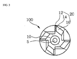
本発明のそのような面取り工具の別の実施態様は、図3および4に示されたように、4枚のカッター刃(20)が備えられている点において上記の実施態様とは異なっている。さらに、半径方向第2逃げ角は、35〜45度の範囲内で選択され、上記の実施態様とは異なっている。4枚のカッター刃(20)が備えられているので、該半径方向第2逃げ角は変わる。半径方向第1逃げ角を含む他の因子は、上記の実施態様のそれらと類似であり、したがって詳細な記載はなされない。 Another embodiment of such a chamfering tool of the present invention differs from the above embodiment in that four cutter blades (20) are provided, as shown in FIGS. . Further, the second radial clearance angle is selected within the range of 35 to 45 degrees, which is different from the above embodiment. Since four cutter blades (20) are provided, the second radial clearance angle changes. Other factors, including the first radial clearance angle, are similar to those of the above embodiment and are therefore not described in detail.
以下の記載は、上記の構成を有する本発明の面取り工具を空気式若しくは電気式工具上に搭載する仕方および加工物を面取り加工する仕方を示している。 The following description shows how to mount the chamfering tool of the present invention having the above configuration on a pneumatic or electric tool and how to chamfer a workpiece.
本発明の実施態様における面取り加工具(100)は、シャンク(40)の反対側のねじ穴(90)内に空気式若しくは電気式工具の回転軸を挿入し固定することによって、空気式若しくは電気式工具(図示されない)に固定されている。空気式若しくは電気式工具に固定された面取り加工具(100)を用い、面取り加工具(100)が加工物(図示されない)と接触され、電力スイッチが入れられるとき、駆動ユニットが作動しそして面取り加工具(100)のカッター刃(20)を回転させる。 The chamfering tool (100) according to the embodiment of the present invention includes a pneumatic or electric tool by inserting and fixing a rotary shaft of a pneumatic or electric tool in the screw hole (90) on the opposite side of the shank (40). Fixed to a tool (not shown). Using a chamfering tool (100) fixed to a pneumatic or electric tool, when the chamfering tool (100) is brought into contact with the workpiece (not shown) and the power switch is turned on, the drive unit is activated and the chamfering The cutter blade (20) of the processing tool (100) is rotated.
カッター刃(20)が回転すると、加工物に対する面取り加工が始まる。 When the cutter blade (20) rotates, chamfering on the workpiece starts.
カッター刃(20)の面取り表面によって作られる切屑(図示されない)は、加工物を面取り加工する間、排出溝(30)を通って排出される。さらに、カッター刃(20)は一般的にコートされ、従ってカッター刃(20)の表面を損傷することなく切屑は容易に排出される。 Chips (not shown) created by the chamfered surface of the cutter blade (20) are discharged through the discharge groove (30) while chamfering the workpiece. Furthermore, the cutter blade (20) is generally coated so that the chips are easily discharged without damaging the surface of the cutter blade (20).
カッター刃(20)は半径方向第1刃(14)の片側に研磨された部分(12)を有しているので、カッター刃(20)は、破壊から守られ、且つ加工物の表面仕上げは加工物の面取り加工において改善されうる。さらに、微粒子が研磨された部分(12)において焼結され、従って面取り加工は、高速回転においてさえ非常に鋭い輪郭をもつカッター刃によって実施されることができ、同時にカッター刃(20)の寿命時間がかなり延ばされ且つ高品質面が達成されうる。 Since the cutter blade (20) has a polished portion (12) on one side of the radial first blade (14), the cutter blade (20) is protected from breakage and the surface finish of the workpiece is It can be improved in the chamfering of the workpiece. Furthermore, the fine particles are sintered in the polished part (12), so that the chamfering can be carried out with a cutter blade having a very sharp profile even at high speed rotation, while at the same time the lifetime of the cutter blade (20). Can be extended considerably and high quality aspects can be achieved.
半径方向第1刃(14)は、10〜20度の範囲の半径方向第1逃げ角を有しているので、面取り加工において生成される負荷は減らされうる。さらに、半径方向第1刃(14)は半径方向第1逃げ角を有しているので、カッター刃への損傷を軽減するだけでなく、切削のための最適状態を提供することも可能である。さらに、半径方向第1刃(14)と接続された半径方向第2刃(16)の半径方向第2逃げ角が25〜35度の範囲であるので、面取り加工の間、十分な間隙が加工物と半径方向第1刃(14)との間で保障され、それによって機械的干渉およびチャタリングが防止されうる。加えて、カッター刃(20)は、半径方向第2逃げ角のおかげで切削方向にスムーズに動くことができる。本発明のこの実施態様は、カッター刃の枚数を4枚に変えることによってユーザの要求に合わせるように構成された。さらに、本発明のこの実施態様に従う面取り加工具の操作は、上記の実施態様のそれとほとんど同じであり、それゆえここでは記載しない。 Since the first radial blade (14) has a first radial clearance angle in the range of 10 to 20 degrees, the load generated in the chamfering process can be reduced. Furthermore, since the first radial blade (14) has a first radial clearance angle, it is possible not only to reduce damage to the cutter blade, but also to provide an optimal state for cutting. . Furthermore, since the second radial clearance angle of the second radial blade (16) connected to the first radial blade (14) is in the range of 25 to 35 degrees, a sufficient gap is formed during chamfering. It can be ensured between the object and the first radial blade (14), whereby mechanical interference and chattering can be prevented. In addition, the cutter blade (20) can move smoothly in the cutting direction thanks to the radial second clearance angle. This embodiment of the present invention was configured to meet user requirements by changing the number of cutter blades to four. Furthermore, the operation of the chamfering tool according to this embodiment of the invention is almost the same as that of the above embodiment and is therefore not described here.
本発明の面取り加工具は、上記複数の実施態様に限定されるものではない。本発明は、請求項に記載された本発明の精神と範囲から逸脱することなく、当業者によって様々な方法で変形されうる。そして、そのような変形は本発明の範囲内に包含されていることが理解されるべきである。 The chamfering tool of the present invention is not limited to the plurality of embodiments. The present invention can be modified in various ways by those skilled in the art without departing from the spirit and scope of the present invention as described in the claims. And it should be understood that such variations are included within the scope of the present invention.
産業的利用
本発明の面取り加工具は、カッターを実装された、さらには加工物の端部および真直ぐな平面を加工するための複数のカッターを実装された様々なタイプの面取り加工機械に使用可能である。
Industrial Application The chamfering tool of the present invention can be used in various types of chamfering machines equipped with a cutter and further equipped with a plurality of cutters for machining the end of a workpiece and a straight plane. It is.
5 軸穴
10 本体
14 半径方向第1刃
16 半径方向第2刃
20 カッター刃
30 排出溝
40 シャンク
50、90 ねじ穴
60 軸受
65 突出部
5
Claims (10)
中心を通り形成された軸穴を有する本体;該本体の周表面上に所定の間隔で配置された複数のカッター刃、ここで、該刃の各々は、10〜20度の範囲の半径方向第1逃げ角をもつ半径方向第1刃および25〜35度の範囲の半径方向第2逃げ角をもつ半径方向第2刃を有する;面取り加工において作られた切屑を排出するために複数の該カッター刃の間に縦方向に形成された排出溝;および該本体の該軸穴に挿入されたシャンク;
を備え、該本体と該シャンクとはろう付けによって接続されている、
上記面取り加工具。 A chamfering tool,
A body having a shaft hole formed through the center; a plurality of cutter blades disposed at predetermined intervals on a circumferential surface of the body, wherein each of the blades has a radial dimension in the range of 10 to 20 degrees; A first radial blade having a clearance angle and a second radial blade having a second radial clearance angle in the range of 25 to 35 degrees; a plurality of the cutters for discharging chips produced in chamfering Discharge grooves formed longitudinally between the blades; and a shank inserted into the shaft hole of the body;
The body and the shank are connected by brazing,
The chamfering tool.
中心を通り形成された軸穴を有する本体;該本体の周表面上に所定の間隔で配置された複数のカッター刃、ここで、該刃の各々は、10〜20度の範囲の半径方向第1逃げ角をもつ半径方向第1刃および35〜45度の範囲の半径方向第2逃げ角をもつ半径方向第2刃を有する;面取り加工において作られた切屑を排出するために複数の該カッター刃の間に縦方向に形成された排出溝;および該本体の該軸穴に挿入されたシャンク;
を備え、該本体と該シャンクとはろう付けによって接続されている、
上記面取り加工具。 A chamfering tool,
A body having a shaft hole formed through the center; a plurality of cutter blades disposed at predetermined intervals on a circumferential surface of the body, wherein each of the blades has a radial dimension in the range of 10 to 20 degrees; A first radial blade having a clearance angle and a second radial blade having a second radial clearance angle in the range of 35 to 45 degrees; a plurality of the cutters for discharging chips produced in chamfering Discharge grooves formed longitudinally between the blades; and a shank inserted into the shaft hole of the body;
The body and the shank are connected by brazing,
The chamfering tool.
Applications Claiming Priority (5)
| Application Number | Priority Date | Filing Date | Title |
|---|---|---|---|
| KR1020120073019A KR101555040B1 (en) | 2012-07-04 | 2012-07-04 | Beveling Tool |
| KR10-2012-0073019 | 2012-07-04 | ||
| US201361956558P | 2013-06-11 | 2013-06-11 | |
| US61/956,558 | 2013-06-11 | ||
| PCT/NL2013/000038 WO2014007609A1 (en) | 2012-07-04 | 2013-07-01 | Beveling / chamfering tool - router head for metal |
Publications (2)
| Publication Number | Publication Date |
|---|---|
| JP2015521959A true JP2015521959A (en) | 2015-08-03 |
| JP2015521959A5 JP2015521959A5 (en) | 2016-08-18 |
Family
ID=48906473
Family Applications (1)
| Application Number | Title | Priority Date | Filing Date |
|---|---|---|---|
| JP2015520085A Pending JP2015521959A (en) | 2012-07-04 | 2013-07-01 | Chamfering / Beveling Tool-Router Head for Metal |
Country Status (9)
| Country | Link |
|---|---|
| EP (1) | EP2869956B1 (en) |
| JP (1) | JP2015521959A (en) |
| KR (1) | KR101555040B1 (en) |
| CN (1) | CN104540627A (en) |
| AU (1) | AU2013285687B2 (en) |
| BR (1) | BR112014032946A2 (en) |
| CA (1) | CA2878058C (en) |
| ES (1) | ES2715318T3 (en) |
| WO (1) | WO2014007609A1 (en) |
Cited By (1)
| Publication number | Priority date | Publication date | Assignee | Title |
|---|---|---|---|---|
| WO2021090525A1 (en) * | 2019-11-06 | 2021-05-14 | 株式会社ジーベックテクノロジー | Beveling cutter and method for beveling workpiece |
Families Citing this family (2)
| Publication number | Priority date | Publication date | Assignee | Title |
|---|---|---|---|---|
| CN108788265B (en) * | 2017-05-05 | 2020-08-18 | 张新添 | Disposable chamfering tool |
| KR102410206B1 (en) * | 2022-05-10 | 2022-06-22 | 주식회사 에스이 | Cutting tool for changing nozzle of nuclear power plant |
Citations (9)
| Publication number | Priority date | Publication date | Assignee | Title |
|---|---|---|---|---|
| US2874616A (en) * | 1954-02-15 | 1959-02-24 | Cardinal Oliver Vetal | Radius and chamfer cutter assembly |
| JPS62168209U (en) * | 1986-04-16 | 1987-10-26 | ||
| JPS63140314U (en) * | 1987-03-09 | 1988-09-14 | ||
| JPH0871831A (en) * | 1994-09-08 | 1996-03-19 | Mitsubishi Materials Corp | End mill |
| JPH09192915A (en) * | 1996-01-18 | 1997-07-29 | Yutaka Giken Co Ltd | Ball end mill |
| JP2005028502A (en) * | 2003-07-11 | 2005-02-03 | Mitsubishi Materials Corp | Chamfering cutter, and throwaway tip for chamfering cutter |
| JP3111276U (en) * | 2005-04-11 | 2005-07-14 | 株式会社デッケル・グラインダー ジャパン | Chamfering end mill |
| JP2007075944A (en) * | 2005-09-14 | 2007-03-29 | Tungaloy Corp | Ball end mill |
| CH701414A1 (en) * | 2009-07-09 | 2011-01-14 | Fraisa Holding Ag | Milling tool for rotary material erosive operation of fiber-reinforced composites, particularly fiber-reinforced plastics or carbon fiber reinforced plastics, has shaft for fixing milling tool in tool machine |
Family Cites Families (15)
| Publication number | Priority date | Publication date | Assignee | Title |
|---|---|---|---|---|
| BG19649A1 (en) * | 1973-11-14 | 1975-10-10 | ||
| DE3170064D1 (en) * | 1980-12-24 | 1985-05-23 | Fuji Heavy Ind Ltd | Router bit |
| JPS61252015A (en) * | 1985-04-30 | 1986-11-10 | Hitachi Ltd | End mill with cutting edge for chamfering |
| CN1024767C (en) * | 1990-04-07 | 1994-06-01 | 伊斯卡硬金属股份有限公司 | Cutting insert for milling cutting tool |
| US6048142A (en) * | 1992-06-10 | 2000-04-11 | Matsushita Electric Industrial Co., Ltd. | Profiling method |
| JPH06226522A (en) * | 1993-02-04 | 1994-08-16 | Asahi Kogu Seisakusho:Kk | End mill |
| US5352072A (en) * | 1993-03-01 | 1994-10-04 | Fred M. Velepec Co., Inc. | Cutting tool with guide for trimming laminate |
| KR200276131Y1 (en) * | 2002-02-14 | 2002-05-21 | 손석엽 | A chamferring tool for edge cutting |
| US7103950B1 (en) * | 2002-07-11 | 2006-09-12 | Douglas Scheffer | Pipe beveling tool and method |
| DE20310713U1 (en) * | 2003-07-12 | 2003-09-18 | Fette Gmbh | end mill |
| JP2005238414A (en) * | 2004-02-27 | 2005-09-08 | Kanefusa Corp | End mill with chamfering blade |
| DE202006006114U1 (en) * | 2006-04-15 | 2006-06-14 | Günther Wirth Hartmetallwerkzeuge GmbH & Co. KG | Cylindrical milling tool has multiple spiral-shaped major cutting edges which possess open space with setting angle of at least eight degree and having a certain width |
| DE102008034784B4 (en) * | 2008-06-13 | 2023-04-13 | Gühring KG | Milling tool for milling fiber-reinforced plastics |
| KR100913411B1 (en) * | 2008-08-21 | 2009-08-21 | 김용범 | Cutter for chamfering |
| WO2011105420A1 (en) * | 2010-02-24 | 2011-09-01 | 京セラ株式会社 | Cutting tool |
-
2012
- 2012-07-04 KR KR1020120073019A patent/KR101555040B1/en active IP Right Grant
-
2013
- 2013-07-01 CA CA2878058A patent/CA2878058C/en active Active
- 2013-07-01 AU AU2013285687A patent/AU2013285687B2/en active Active
- 2013-07-01 BR BR112014032946A patent/BR112014032946A2/en not_active IP Right Cessation
- 2013-07-01 JP JP2015520085A patent/JP2015521959A/en active Pending
- 2013-07-01 ES ES13742760T patent/ES2715318T3/en active Active
- 2013-07-01 WO PCT/NL2013/000038 patent/WO2014007609A1/en active Application Filing
- 2013-07-01 EP EP13742760.5A patent/EP2869956B1/en active Active
- 2013-07-01 CN CN201380035194.2A patent/CN104540627A/en active Pending
Patent Citations (9)
| Publication number | Priority date | Publication date | Assignee | Title |
|---|---|---|---|---|
| US2874616A (en) * | 1954-02-15 | 1959-02-24 | Cardinal Oliver Vetal | Radius and chamfer cutter assembly |
| JPS62168209U (en) * | 1986-04-16 | 1987-10-26 | ||
| JPS63140314U (en) * | 1987-03-09 | 1988-09-14 | ||
| JPH0871831A (en) * | 1994-09-08 | 1996-03-19 | Mitsubishi Materials Corp | End mill |
| JPH09192915A (en) * | 1996-01-18 | 1997-07-29 | Yutaka Giken Co Ltd | Ball end mill |
| JP2005028502A (en) * | 2003-07-11 | 2005-02-03 | Mitsubishi Materials Corp | Chamfering cutter, and throwaway tip for chamfering cutter |
| JP3111276U (en) * | 2005-04-11 | 2005-07-14 | 株式会社デッケル・グラインダー ジャパン | Chamfering end mill |
| JP2007075944A (en) * | 2005-09-14 | 2007-03-29 | Tungaloy Corp | Ball end mill |
| CH701414A1 (en) * | 2009-07-09 | 2011-01-14 | Fraisa Holding Ag | Milling tool for rotary material erosive operation of fiber-reinforced composites, particularly fiber-reinforced plastics or carbon fiber reinforced plastics, has shaft for fixing milling tool in tool machine |
Non-Patent Citations (1)
| Title |
|---|
| "ブルガリア国発明者証第19649号明細書", BG 19649 A1, JPN6017025057, 10 October 1975 (1975-10-10), BG, ISSN: 0004009249 * |
Cited By (1)
| Publication number | Priority date | Publication date | Assignee | Title |
|---|---|---|---|---|
| WO2021090525A1 (en) * | 2019-11-06 | 2021-05-14 | 株式会社ジーベックテクノロジー | Beveling cutter and method for beveling workpiece |
Also Published As
| Publication number | Publication date |
|---|---|
| CN104540627A (en) | 2015-04-22 |
| KR20140005531A (en) | 2014-01-15 |
| EP2869956A1 (en) | 2015-05-13 |
| AU2013285687A1 (en) | 2015-01-22 |
| EP2869956B1 (en) | 2018-12-26 |
| BR112014032946A2 (en) | 2017-06-27 |
| CA2878058A1 (en) | 2014-01-09 |
| WO2014007609A8 (en) | 2014-02-13 |
| CA2878058C (en) | 2021-12-14 |
| KR101555040B1 (en) | 2015-09-22 |
| AU2013285687B2 (en) | 2017-02-16 |
| WO2014007609A1 (en) | 2014-01-09 |
| ES2715318T3 (en) | 2019-06-03 |
Similar Documents
| Publication | Publication Date | Title |
|---|---|---|
| WO2007142224A1 (en) | Cutting tool and cutting insert | |
| WO2010092807A1 (en) | Cutting toll with cutting inserts and cutting insert therefor | |
| US9623491B2 (en) | Beveling / chamfering tool—router head for metal | |
| TWI624320B (en) | Milling tool | |
| JP6432989B2 (en) | Chamfering cutter with helical pointed blade and discharge groove | |
| JP2015521959A (en) | Chamfering / Beveling Tool-Router Head for Metal | |
| CN216912223U (en) | Cutter for processing lens hole shape and forming machine | |
| JP2008290167A (en) | Cutting device | |
| US7841810B2 (en) | Milling cutter head | |
| KR200449753Y1 (en) | Modular type double face shrink fit chuck having guiding surface | |
| JP5433344B2 (en) | Composite tool, machine tool and machining method | |
| JP2010046733A (en) | Thread milling cutter | |
| US9782843B2 (en) | Beveling cutter having helical edged blades and discharge grooves | |
| JP2006150535A (en) | Cutting tool | |
| JP2010149231A (en) | Cutting tool and method of polishing the same | |
| CN209830397U (en) | Machining device for machining deep groove on lathe | |
| CN215090919U (en) | External circle sleeved chamfering tool | |
| KR200449752Y1 (en) | Modular type double face shrink fit chuck | |
| TWM591012U (en) | Compound cutter | |
| JP2010149230A (en) | Cutting tool and method of polishing the same | |
| JP2002355702A (en) | Cutting tool | |
| KR20170036277A (en) | Chamfering machine | |
| JP2023034892A (en) | Cutting tool | |
| JP2023119516A (en) | Lathe tool for combined processing machine | |
| JP2002096212A (en) | Flat type cutting blade for blade head, disc type blade head and hand power tool |
Legal Events
| Date | Code | Title | Description |
|---|---|---|---|
| A521 | Request for written amendment filed |
Free format text: JAPANESE INTERMEDIATE CODE: A523 Effective date: 20150519 |
|
| A521 | Request for written amendment filed |
Free format text: JAPANESE INTERMEDIATE CODE: A523 Effective date: 20160630 |
|
| A621 | Written request for application examination |
Free format text: JAPANESE INTERMEDIATE CODE: A621 Effective date: 20160630 |
|
| A977 | Report on retrieval |
Free format text: JAPANESE INTERMEDIATE CODE: A971007 Effective date: 20170519 |
|
| A131 | Notification of reasons for refusal |
Free format text: JAPANESE INTERMEDIATE CODE: A131 Effective date: 20170719 |
|
| A601 | Written request for extension of time |
Free format text: JAPANESE INTERMEDIATE CODE: A601 Effective date: 20171019 |
|
| A131 | Notification of reasons for refusal |
Free format text: JAPANESE INTERMEDIATE CODE: A131 Effective date: 20180611 |
|
| A601 | Written request for extension of time |
Free format text: JAPANESE INTERMEDIATE CODE: A601 Effective date: 20180903 |
|
| A711 | Notification of change in applicant |
Free format text: JAPANESE INTERMEDIATE CODE: A711 Effective date: 20181015 |
|
| A601 | Written request for extension of time |
Free format text: JAPANESE INTERMEDIATE CODE: A601 Effective date: 20181109 |
|
| A02 | Decision of refusal |
Free format text: JAPANESE INTERMEDIATE CODE: A02 Effective date: 20190411 |