WO2021085246A1 - 撮像支援装置、撮像支援システム、撮像システム、撮像支援方法、及びプログラム - Google Patents
撮像支援装置、撮像支援システム、撮像システム、撮像支援方法、及びプログラム Download PDFInfo
- Publication number
- WO2021085246A1 WO2021085246A1 PCT/JP2020/039424 JP2020039424W WO2021085246A1 WO 2021085246 A1 WO2021085246 A1 WO 2021085246A1 JP 2020039424 W JP2020039424 W JP 2020039424W WO 2021085246 A1 WO2021085246 A1 WO 2021085246A1
- Authority
- WO
- WIPO (PCT)
- Prior art keywords
- image
- imaging
- subject image
- captured image
- alignment control
- Prior art date
- Legal status (The legal status is an assumption and is not a legal conclusion. Google has not performed a legal analysis and makes no representation as to the accuracy of the status listed.)
- Ceased
Links
Images


Classifications
-
- H—ELECTRICITY
- H04—ELECTRIC COMMUNICATION TECHNIQUE
- H04N—PICTORIAL COMMUNICATION, e.g. TELEVISION
- H04N23/00—Cameras or camera modules comprising electronic image sensors; Control thereof
- H04N23/60—Control of cameras or camera modules
- H04N23/68—Control of cameras or camera modules for stable pick-up of the scene, e.g. compensating for camera body vibrations
- H04N23/682—Vibration or motion blur correction
- H04N23/685—Vibration or motion blur correction performed by mechanical compensation
-
- G—PHYSICS
- G02—OPTICS
- G02B—OPTICAL ELEMENTS, SYSTEMS OR APPARATUS
- G02B27/00—Optical systems or apparatus not provided for by any of the groups G02B1/00 - G02B26/00, G02B30/00
- G02B27/64—Imaging systems using optical elements for stabilisation of the lateral and angular position of the image
- G02B27/646—Imaging systems using optical elements for stabilisation of the lateral and angular position of the image compensating for small deviations, e.g. due to vibration or shake
-
- F—MECHANICAL ENGINEERING; LIGHTING; HEATING; WEAPONS; BLASTING
- F16—ENGINEERING ELEMENTS AND UNITS; GENERAL MEASURES FOR PRODUCING AND MAINTAINING EFFECTIVE FUNCTIONING OF MACHINES OR INSTALLATIONS; THERMAL INSULATION IN GENERAL
- F16M—FRAMES, CASINGS OR BEDS OF ENGINES, MACHINES OR APPARATUS, NOT SPECIFIC TO ENGINES, MACHINES OR APPARATUS PROVIDED FOR ELSEWHERE; STANDS; SUPPORTS
- F16M11/00—Stands or trestles as supports for apparatus or articles placed thereon ; Stands for scientific apparatus such as gravitational force meters
- F16M11/02—Heads
- F16M11/04—Means for attachment of apparatus; Means allowing adjustment of the apparatus relatively to the stand
- F16M11/06—Means for attachment of apparatus; Means allowing adjustment of the apparatus relatively to the stand allowing pivoting
- F16M11/10—Means for attachment of apparatus; Means allowing adjustment of the apparatus relatively to the stand allowing pivoting around a horizontal axis
-
- F—MECHANICAL ENGINEERING; LIGHTING; HEATING; WEAPONS; BLASTING
- F16—ENGINEERING ELEMENTS AND UNITS; GENERAL MEASURES FOR PRODUCING AND MAINTAINING EFFECTIVE FUNCTIONING OF MACHINES OR INSTALLATIONS; THERMAL INSULATION IN GENERAL
- F16M—FRAMES, CASINGS OR BEDS OF ENGINES, MACHINES OR APPARATUS, NOT SPECIFIC TO ENGINES, MACHINES OR APPARATUS PROVIDED FOR ELSEWHERE; STANDS; SUPPORTS
- F16M11/00—Stands or trestles as supports for apparatus or articles placed thereon ; Stands for scientific apparatus such as gravitational force meters
- F16M11/02—Heads
- F16M11/18—Heads with mechanism for moving the apparatus relatively to the stand
-
- F—MECHANICAL ENGINEERING; LIGHTING; HEATING; WEAPONS; BLASTING
- F16—ENGINEERING ELEMENTS AND UNITS; GENERAL MEASURES FOR PRODUCING AND MAINTAINING EFFECTIVE FUNCTIONING OF MACHINES OR INSTALLATIONS; THERMAL INSULATION IN GENERAL
- F16M—FRAMES, CASINGS OR BEDS OF ENGINES, MACHINES OR APPARATUS, NOT SPECIFIC TO ENGINES, MACHINES OR APPARATUS PROVIDED FOR ELSEWHERE; STANDS; SUPPORTS
- F16M11/00—Stands or trestles as supports for apparatus or articles placed thereon ; Stands for scientific apparatus such as gravitational force meters
- F16M11/20—Undercarriages with or without wheels
- F16M11/2007—Undercarriages with or without wheels comprising means allowing pivoting adjustment
- F16M11/2014—Undercarriages with or without wheels comprising means allowing pivoting adjustment around a vertical axis
-
- G—PHYSICS
- G03—PHOTOGRAPHY; CINEMATOGRAPHY; ANALOGOUS TECHNIQUES USING WAVES OTHER THAN OPTICAL WAVES; ELECTROGRAPHY; HOLOGRAPHY
- G03B—APPARATUS OR ARRANGEMENTS FOR TAKING PHOTOGRAPHS OR FOR PROJECTING OR VIEWING THEM; APPARATUS OR ARRANGEMENTS EMPLOYING ANALOGOUS TECHNIQUES USING WAVES OTHER THAN OPTICAL WAVES; ACCESSORIES THEREFOR
- G03B15/00—Special procedures for taking photographs; Apparatus therefor
-
- G—PHYSICS
- G03—PHOTOGRAPHY; CINEMATOGRAPHY; ANALOGOUS TECHNIQUES USING WAVES OTHER THAN OPTICAL WAVES; ELECTROGRAPHY; HOLOGRAPHY
- G03B—APPARATUS OR ARRANGEMENTS FOR TAKING PHOTOGRAPHS OR FOR PROJECTING OR VIEWING THEM; APPARATUS OR ARRANGEMENTS EMPLOYING ANALOGOUS TECHNIQUES USING WAVES OTHER THAN OPTICAL WAVES; ACCESSORIES THEREFOR
- G03B17/00—Details of cameras or camera bodies; Accessories therefor
- G03B17/56—Accessories
-
- G—PHYSICS
- G03—PHOTOGRAPHY; CINEMATOGRAPHY; ANALOGOUS TECHNIQUES USING WAVES OTHER THAN OPTICAL WAVES; ELECTROGRAPHY; HOLOGRAPHY
- G03B—APPARATUS OR ARRANGEMENTS FOR TAKING PHOTOGRAPHS OR FOR PROJECTING OR VIEWING THEM; APPARATUS OR ARRANGEMENTS EMPLOYING ANALOGOUS TECHNIQUES USING WAVES OTHER THAN OPTICAL WAVES; ACCESSORIES THEREFOR
- G03B5/00—Adjustment of optical system relative to image or object surface other than for focusing
-
- H—ELECTRICITY
- H04—ELECTRIC COMMUNICATION TECHNIQUE
- H04N—PICTORIAL COMMUNICATION, e.g. TELEVISION
- H04N23/00—Cameras or camera modules comprising electronic image sensors; Control thereof
- H04N23/60—Control of cameras or camera modules
- H04N23/63—Control of cameras or camera modules by using electronic viewfinders
- H04N23/631—Graphical user interfaces [GUI] specially adapted for controlling image capture or setting capture parameters
- H04N23/632—Graphical user interfaces [GUI] specially adapted for controlling image capture or setting capture parameters for displaying or modifying preview images prior to image capturing, e.g. variety of image resolutions or capturing parameters
-
- H—ELECTRICITY
- H04—ELECTRIC COMMUNICATION TECHNIQUE
- H04N—PICTORIAL COMMUNICATION, e.g. TELEVISION
- H04N23/00—Cameras or camera modules comprising electronic image sensors; Control thereof
- H04N23/60—Control of cameras or camera modules
- H04N23/68—Control of cameras or camera modules for stable pick-up of the scene, e.g. compensating for camera body vibrations
- H04N23/681—Motion detection
- H04N23/6812—Motion detection based on additional sensors, e.g. acceleration sensors
-
- H—ELECTRICITY
- H04—ELECTRIC COMMUNICATION TECHNIQUE
- H04N—PICTORIAL COMMUNICATION, e.g. TELEVISION
- H04N23/00—Cameras or camera modules comprising electronic image sensors; Control thereof
- H04N23/60—Control of cameras or camera modules
- H04N23/68—Control of cameras or camera modules for stable pick-up of the scene, e.g. compensating for camera body vibrations
- H04N23/682—Vibration or motion blur correction
- H04N23/685—Vibration or motion blur correction performed by mechanical compensation
- H04N23/687—Vibration or motion blur correction performed by mechanical compensation by shifting the lens or sensor position
-
- H—ELECTRICITY
- H04—ELECTRIC COMMUNICATION TECHNIQUE
- H04N—PICTORIAL COMMUNICATION, e.g. TELEVISION
- H04N23/00—Cameras or camera modules comprising electronic image sensors; Control thereof
- H04N23/60—Control of cameras or camera modules
- H04N23/69—Control of means for changing angle of the field of view, e.g. optical zoom objectives or electronic zooming
-
- H—ELECTRICITY
- H04—ELECTRIC COMMUNICATION TECHNIQUE
- H04N—PICTORIAL COMMUNICATION, e.g. TELEVISION
- H04N23/00—Cameras or camera modules comprising electronic image sensors; Control thereof
- H04N23/60—Control of cameras or camera modules
- H04N23/695—Control of camera direction for changing a field of view, e.g. pan, tilt or based on tracking of objects
Definitions
- the technology of the present disclosure relates to an imaging support device, an imaging support system, an imaging system, an imaging support method, and a program.
- Japanese Unexamined Patent Publication No. 2019-102833 discloses an imaging device including a first driving means, a second driving means moving means, and a controlling means.
- the first driving means rotates the imaging direction of the imaging means in the first direction.
- the second driving means rotates the imaging direction of the imaging means in a second direction orthogonal to the first direction.
- the control means controls the first driving means or the second driving means, and executes the shake correction control for correcting the image shake caused by the shake applied to the image pickup means.
- the control means switches the runout correction control using the first drive means or the second drive means according to the rotation angle by the second drive means.
- Japanese Unexamined Patent Publication No. 2015-130612 discloses an imaging apparatus including an imaging means, a correction member, a prediction means, and a control means.
- the imaging means captures a subject and outputs a video signal.
- the correction member executes the first correction for correcting the image shake that occurs in the image related to the image signal due to the camera shake.
- the prediction means predicts the moving direction of the subject.
- the control means has a function of driving the correction member to execute the first correction, and by driving the correction member according to the predicted moving direction of the subject, the direction in which the subject at the shooting angle of view moves. Perform a second complement to free up space.
- Japanese Unexamined Patent Publication No. 2015-307248 discloses an imaging device including a shake correction means, a subject detection means, and a control means.
- the subject detecting means detects a subject from an image.
- the control means controls the drive of the runout correction means and also controls the zoom position.
- the control means controls the drive of the shake correction means according to the position of the subject detected by the subject detection means, and controls the zoom position to move to the wide-angle side when the subject is included outside the first angle of view. ..
- the subject image position is captured even when the subject image position is deviated from the captured image by scaling to the telephoto side in an imaging device having a scaling mechanism.
- an image pickup support device an image pickup support system, an image pickup system, an image pickup support method, and a program capable of adjusting to a specific position in the image.
- the first aspect according to the technique of the present disclosure is an object in a captured image obtained by capturing an imaging region including a target subject by the imaging device by operating a swivel mechanism that rotates an imaging device having a scaling mechanism.
- the detection unit detects the position of the subject image of the target subject image indicating the subject, and the image captured by the image pickup device as the magnification changes to the telephoto side by the scaling mechanism.
- the image pickup apparatus has a runout correction unit that corrects the runout caused by the vibration given to the image pickup apparatus, and the alignment control is detected by the detection unit.
- This is an imaging support device according to a first aspect, which is a control including a control of adjusting a subject image position to a specific position by operating a shake correction unit.
- a third aspect according to the technique of the present disclosure is the first aspect or the first aspect in which the alignment control is a control including a control of adjusting the subject image position detected by the detection unit to a specific position by operating a turning mechanism.
- the alignment control is a control including a control of adjusting the subject image position detected by the detection unit to a specific position by operating a turning mechanism.
- This is an image pickup support device according to the second aspect.
- the image pickup apparatus has a shake correction unit for correcting shake caused by vibration given to the image pickup apparatus, and the control unit is a subject detected by the detection unit.
- the image pickup support device which includes performing alignment control by operating at least one of a runout correction unit and a swivel mechanism according to an offset amount of an image position with respect to a specific position.
- a fifth aspect according to the technique of the present disclosure is the operation of a scaling mechanism and a swivel mechanism for swirling an image pickup device having a shake correction unit for correcting shake caused by a given vibration, thereby using the image pickup device.
- a detection unit that detects the subject image position of the target subject image that indicates the target subject in the captured image obtained by capturing the imaging area including the target subject, and imaging with the scaling to the telephoto side by the scaling mechanism.
- the subject image position detected by the detection unit is subjected to the shake correction unit and the swivel mechanism according to the offset amount of the subject image position detected by the detection unit with respect to the specific position.
- a sixth aspect according to the technique of the present disclosure is that the alignment control is higher than the first alignment control for moving the subject image position toward a specific position by operating the swivel mechanism and the first alignment control.
- the image pickup support device according to the fourth aspect or the fifth aspect of performing the second alignment control.
- the control unit sets the subject image position to a specific position by operating the swivel mechanism.
- control unit performs scaling toward the telescopic side while the target subject image is displayed on the captured image, so that at least a part of the target subject image is transmitted from the captured image.
- Alignment control is performed when the image is out of alignment, and the specific position is the position defined as the position where the target subject image fits in the captured image. It is a device.
- a ninth aspect according to the technique of the present disclosure is that the positioning accuracy of the swivel angle by the swivel mechanism with respect to the imaging range is relatively reduced with the scaling to the telephoto side by the scaling mechanism.
- the imaging support device according to any one of the first to eighth aspects, in which the amount of offset of the subject image position in the image from a specific position increases.
- a tenth aspect according to the technique of the present disclosure is an imaging support according to any one of the first to ninth aspects, wherein the control unit performs positioning control with a specific position as the central position in the captured image. It is a device.
- the variation in the rotation angle of the rotation mechanism at the stop position is the angle of view of the imaging range on the telephoto side.
- the imaging support device according to the tenth aspect which is less than half.
- the twelfth aspect according to the technique of the present disclosure is the image pickup support device according to the eleventh aspect in which the variation is less than half of the angle of view and less than the offset amount.
- a thirteenth aspect according to the technique of the present disclosure includes an image pickup support device and a swivel mechanism according to any one of the first to twelfth aspects, and the image pickup support device is imaged by the swivel mechanism.
- This is an imaging support system that supports imaging by an imaging device when the device is rotated.
- a fourteenth aspect according to the technique of the present disclosure includes an image pickup support device and an image pickup device according to any one of the first to thirteenth aspects, and the image pickup device is imaged by the image pickup support device. It is an imaging system that is supported by.
- a fifteenth aspect according to the technique of the present disclosure further includes a swivel mechanism, which is an imaging system according to a fourteenth aspect of swiveling an imaging device.
- a sixteenth aspect according to the technique of the present disclosure is an object in a captured image obtained by capturing an imaging region including a target subject by the imaging device by operating a swivel mechanism that rotates an imaging device having a scaling mechanism.
- the detected subject image of the captured image obtained by detecting the subject image position of the target subject image indicating the subject and capturing the image by the imaging device with the scaling to the telephoto side by the scaling mechanism.
- This is an imaging support method including performing alignment control to adjust the position to a specific position in the captured image.
- a seventeenth aspect according to the technique of the present disclosure is an captured image obtained by capturing an imaging region including a target subject by the imaging device by operating a rotating mechanism that rotates an imaging device having a scaling mechanism on a computer. It is detected for the captured image obtained by detecting the subject image position of the target subject image indicating the target subject in the inside and by capturing the image by the imaging device with the scaling to the telephoto side by the scaling mechanism.
- This is a program for executing a process including performing alignment control for adjusting the position of the subject image to a specific position in the captured image.
- FIG. 5 is a schematic image diagram showing an example of a mode in which the target subject image is contained in the central region of the captured image by performing the second alignment control included in the alignment control process according to the first embodiment.
- It is a functional block diagram which shows an example of the function of the CPU included in the surveillance camera which concerns on 2nd Embodiment.
- It is a functional block diagram which shows an example of the function of the CPU included in the surveillance camera which concerns on 3rd Embodiment.
- CPU is an abbreviation for "Central Processing Unit”.
- RAM is an abbreviation for "Random Access Memory”.
- ROM is an abbreviation for "Read Only Memory”.
- ASIC is an abbreviation for "Application Specific Integrated Circuit”.
- PLD is an abbreviation for "Programmable Logic Device”.
- FPGA is an abbreviation for "Field-Programmable Gate Array”.
- AFE is an abbreviation for "Analog Front End”.
- DSP is an abbreviation for "Digital Signal Processor”.
- ISP is an abbreviation for "Image Signal Processor”.
- SoC is an abbreviation for "System-on-a-chip”.
- CMOS is an abbreviation for "Complementary Metal Oxide Semiconductor”.
- CCD is an abbreviation for "Charge Coupled Device”.
- SWIR is an abbreviation for "Short-wavelength infrared”.
- SSD is an abbreviation for "Solid State Drive”.
- USB is an abbreviation for “Universal Serial Bus”.
- HDD is an abbreviation for “Hard Disk Drive”.
- EEPROM is an abbreviation for "Electrically Erasable and Programmable Read Only Memory”.
- EL is an abbreviation for "Electro-Luminescence”.
- a / D is an abbreviation for "Analog / Digital”.
- I / F is an abbreviation for "Interface”.
- UI is an abbreviation for "User Interface”.
- WAN is an abbreviation for "Wide Area Network”.
- CRT is an abbreviation for "Cathode Ray Tube”.
- OIS is an abbreviation for "Optical Image Stabilizer”.
- BIS is an abbreviation for "Body Image Stabilizer”.
- horizontal refers to horizontal in the sense of including an error generally allowed in the technical field to which the technology of the present disclosure belongs, in addition to perfect horizontal.
- parallel refers to parallelism in the sense that it includes, in addition to perfect parallelism, errors that are generally acceptable in the art to which the techniques of the present disclosure belong.
- vertical refers to vertical in the sense of being perfectly vertical, as well as including errors that are generally tolerated in the art to which the technology of the present disclosure belongs.
- the term “identical” refers to the exact same, as well as the same in the sense that it includes errors that are generally tolerated in the technical field to which the technology of the present disclosure belongs.
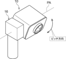
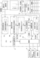
- the surveillance system 2 includes a surveillance camera 10, a management device 11, and a swivel mechanism 16.
- the surveillance system 2 is an example of the "imaging system” or the “imaging support system” according to the technology of the present disclosure
- the surveillance camera 10 is an example of the "imaging apparatus” according to the technology of the present disclosure.
- the surveillance camera 10 is installed on a pillar, a wall, a part of a building (for example, a rooftop) indoors or outdoors via a swivel mechanism 16 described later, and images a monitored object as a subject to capture a moving image. Generate.
- the moving image includes a multi-frame image obtained by imaging.
- the surveillance camera 10 transmits the moving image obtained by capturing the image to the management device 11 via the communication line 12.
- the management device 11 includes a display 13 and a secondary storage device 14.
- Examples of the display 13 include a liquid crystal display, a plasma display, an organic EL display, a CRT display, and the like.
- An HDD is an example of the secondary storage device 14.
- the secondary storage device 14 may be a non-volatile memory such as a flash memory, SSD, or EEPROM instead of an HDD.
- the moving image transmitted by the surveillance camera 10 is received, and the received moving image is displayed on the display 13 or stored in the secondary storage device 14.
- a surveillance camera 10 is attached to the swivel mechanism 16.
- the swivel mechanism 16 enables the surveillance camera 10 to swivel.
- the swivel mechanism 16 intersects the yaw direction and has a swivel direction (hereinafter, referred to as “pitch direction”) with the pitch axis PA as the central axis, and FIG. 3 as an example.
- pitch direction a swivel direction
- FIG. 3 as an example.
- it is a two-axis turning mechanism capable of turning the surveillance camera 10 in a turning direction (hereinafter, referred to as “yaw direction”) about the yaw axis YA as a central axis.
- the swivel mechanism 16 is an example of a "swivel mechanism" according to the technique of the present disclosure.
- the swivel mechanism 16 according to the present embodiment shows an example of a two-axis swivel mechanism, the technique of the present disclosure is not limited to this, and a three-axis swivel mechanism may be used.
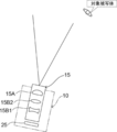
- the surveillance camera 10 includes an optical system 15 and an image sensor 25.
- the image sensor 25 is located after the optical system 15.
- the optical system 15 includes an objective lens 15A and a lens group 15B.
- the objective lens 15A and the lens group 15B are formed of the objective lens 15A and the lens group 15B from the target subject side (object side) to the light receiving surface 25A side (image side) of the image pickup element 25 along the optical axis OA of the optical system 15. They are arranged in order.
- the lens group 15B includes an anti-vibration lens 15B1, a focus lens (not shown), a zoom lens 15B2, and the like.
- the zoom lens 15B2 is movably supported along the optical axis OA by a lens actuator 21 described later.
- the anti-vibration lens 15B1 is movably supported by a lens actuator 17, which will be described later, in a direction orthogonal to the optical axis OA.
- the surveillance camera 10 is an example of an imaging device including a zoom lens 15B2 and having a scaling mechanism with a variable focal length.
- the surveillance camera 10 is on the telephoto side, so that the angle of view becomes smaller (the imaging range becomes narrower).
- the angle of view becomes wider (the imaging range becomes wider) because the angle of view becomes wider.
- the diagram of the scaling mechanism illustrated in the technique of the present disclosure is merely a conceptual diagram, and the scaling mechanism may have various configurations.
- the optical system 15 may include various lenses (not shown) in addition to the objective lens 15A and the lens group 15B. Further, the optical system 15 may include a diaphragm.
- the positions of the lens, the lens group, and the diaphragm included in the optical system 15 are not limited, and the technique of the present disclosure is established even if the positions are different from the positions shown in FIG. 4, for example.
- the anti-vibration lens 15B1 can move in a direction perpendicular to the optical axis OA, and the zoom lens 15B2 can move along the optical axis OA.
- the optical system 15 includes lens actuators 17 and 21.
- the lens actuator 17 exerts a force on the anti-vibration lens 15B1 that fluctuates in the direction perpendicular to the optical axis of the anti-vibration lens 15B1.
- the lens actuator 17 is controlled by the OIS driver 23.
- the position of the anti-vibration lens 15B1 fluctuates in the direction perpendicular to the optical axis OA.
- the actuator 21 exerts a force on the zoom lens 15B2 to move along the optical axis OA of the optical system 15.
- the actuator 21 is controlled by the lens driver 28.
- the position of the zoom lens 15B2 moves along the optical axis OA.
- the focal length of the surveillance camera 10 changes as the position of the zoom lens 15B2 moves along the optical axis OA.
- the angle of view in the pitch axis PA direction is the yaw axis YA direction. It is narrower than the angle of view in, and narrower than the angle of view on the diagonal line.
- the turning amount by the turning mechanism 16 that is, the turning angle (hereinafter, also referred to as "turning amount") may vary due to repeated turning due to the tolerance of each part of the turning mechanism 16. That is, even if an attempt is made to operate the turning mechanism 16 by setting a constant turning amount, for example, 1 degree (60 minutes) in the degree method, the turning angle may be 57 minutes in some cases, and other turns. In that case, the turning angle may be 63 minutes.
- the variation of the turning angle by the turning mechanism 16 is adjusted so as to be less than half of the angle of view on the telephoto side of the surveillance camera 10.
- the variation of the turning angle at the stop position when the turning by the turning mechanism 16 is stopped is adjusted to be less than half of the angle of view on the telephoto side.
- the contour of the captured image is a rectangle having a short side in the pitch axis PA direction and a long side in the yaw axis YA direction
- the rotation is stopped when the rotation by the rotation mechanism 16 is stopped.
- the variation of the turning angle at the position is adjusted so as to be less than half of the angle of view in the pitch axis PA direction (short side direction). Further, the variation of the turning angle by the turning mechanism 16 is adjusted so as to be less than the offset amount described later.
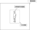
- the position of the target subject image in the captured image (hereinafter, also referred to as “subject image position”) can be aligned with the central region in the captured image.
- the captured image refers to an image obtained by capturing the imaging region by the surveillance camera 10.
- the target subject image refers to an image showing the target subject in the captured image obtained by capturing the imaging region including the target subject by the surveillance camera 10.
- the central region is an example of a "central position" in the art of the present disclosure.
- the light indicating the image pickup region is imaged on the light receiving surface 25A of the image pickup element 25 by the optical system 15 configured in this way, and the image pickup region is imaged by the image pickup element 25.
- the vibration given to the surveillance camera 10 includes vibration caused by the passage of automobiles, vibration caused by wind, vibration caused by road construction, etc. outdoors, and vibration caused by the operation of an air conditioner and people indoors. There is vibration due to the comings and goings of. Therefore, in the surveillance camera 10, vibration occurs due to the vibration given to the surveillance camera 10 (hereinafter, also simply referred to as “vibration”).
- "shake” means that in the surveillance camera 10, the target subject image on the light receiving surface 25A of the image sensor 25 changes due to the change in the positional relationship between the optical axis OA and the light receiving surface 25A.
- "shake” can be said to be a phenomenon in which the optical image obtained by forming an image on the light receiving surface 25A fluctuates due to the tilt of the optical axis OA due to the vibration applied to the surveillance camera 10. .
- the fluctuation of the optical axis OA means that the optical axis OA is tilted with respect to the reference axis (for example, the optical axis OA before the runout occurs).
- the runout caused by vibration is also simply referred to as “runout”.
- the runout is included in the captured image as a noise component and affects the image quality of the captured image. Therefore, in order to remove the noise component contained in the captured image due to the shake, the surveillance camera 10 includes a lens side shake correction mechanism 29, an image sensor side shake correction mechanism 45, and an electronic shake correction unit 33. It is used to correct the runout.
- Each of the lens side shake correction mechanism 29, the image sensor side shake correction mechanism 45, and the electronic shake correction unit 33 is an example of the “shake correction unit (shake correction component)” in the technique of the present disclosure.
- the lens side shake correction mechanism 29 and the image sensor side shake correction mechanism 45 are mechanical shake correction mechanisms.
- the mechanical shake correction mechanism images the shake correction element by applying the power generated by a drive source such as a motor (for example, a voice coil motor) to the shake correction element (for example, an anti-vibration lens and / or an image sensor).
- a drive source such as a motor (for example, a voice coil motor)
- the shake correction element for example, an anti-vibration lens and / or an image sensor.
- the lens-side shake correction mechanism 29 applies the power generated by a drive source such as a motor (for example, a voice coil motor) to the vibration-proof lens to attach the vibration-proof lens to the optical axis of the imaging optical system. It is a mechanism that moves the lens in the direction perpendicular to it and corrects the runout.
- the image sensor side shake correction mechanism 45 applies power generated by a drive source such as a motor (for example, a voice coil motor) to the image sensor to move the image sensor in a direction perpendicular to the optical axis of the image sensor. It is a mechanism that moves and compensates for runout.
- the electronic runout correction unit 33 corrects runout by performing image processing on the captured image based on the runout amount. That is, the runout correction unit (shake correction component) mechanically or electronically corrects the runout in the hardware configuration and / or the software configuration.
- mechanical shake correction means that a shake correction element such as an anti-vibration lens and / or an image sensor is mechanically moved by using a power generated by a drive source such as a motor (for example, a voice coil motor).
- the electronic runout correction refers to, for example, the runout correction realized by performing image processing by a processor.
- the "correction of runout” includes not only the meaning of eliminating the runout but also the meaning of reducing the runout.
- the lens side image stabilization mechanism 29 includes an anti-vibration lens 15B1, a lens actuator 17, an OIS driver 23, and a position detection sensor 39.
- a method of correcting the shake by the lens side shake correction mechanism 29 various well-known methods can be adopted.
- a runout correction method a method of correcting runout by moving the anti-vibration lens 15B1 based on the runout amount detected by the runout amount detection sensor 40 (described later) is adopted.
- the vibration correction is performed by moving the anti-vibration lens 15B1 by the amount of the vibration canceling direction in the direction of canceling the vibration.
- a lens actuator 17 is attached to the anti-vibration lens 15B1.
- the lens actuator 17 is a shift mechanism equipped with a voice coil motor, and drives the voice coil motor to change the anti-vibration lens 15B1 in a direction perpendicular to the optical axis of the anti-vibration lens 15B1.
- the lens actuator 17 employs a shift mechanism equipped with a voice coil motor, but the technique of the present disclosure is not limited to this, and instead of the voice coil motor, a stepping motor or a piezo element is used. Other power sources such as may be applied.
- the lens actuator 17 is controlled by the OIS driver 23.
- the position of the anti-vibration lens 15B1 mechanically fluctuates in a two-dimensional plane perpendicular to the optical axis OA.
- the position detection sensor 39 detects the current position of the anti-vibration lens 15B1 and outputs a position signal indicating the detected current position.
- a device including a Hall element is adopted as an example of the position detection sensor 39.
- the current position of the anti-vibration lens 15B1 refers to the current position in the two-dimensional plane of the anti-vibration lens.
- the anti-vibration lens two-dimensional plane refers to a two-dimensional plane perpendicular to the optical axis of the anti-vibration lens 15B1.
- a device including a Hall element is adopted as an example of the position detection sensor 39, but the technique of the present disclosure is not limited to this, and instead of the Hall element, a magnetic sensor, a photo sensor, or the like is used. May be adopted.
- the lens-side shake correction mechanism 29 corrects runout by moving the anti-vibration lens 15B1 along at least one of the pitch axis PA direction and the yaw axis YA direction in the range actually imaged. That is, the lens-side shake correction mechanism 29 corrects the shake by moving the vibration-proof lens 15B1 in the two-dimensional plane of the vibration-proof lens with a movement amount corresponding to the shake amount.
- the lens side shake correction mechanism 29 moves the subject image position to the central region in the captured image by executing the alignment control process described later.
- the "central region” is a region including the center of the captured image, and the four sides of the central region are separated from the four sides of the contour of the captured image.
- the state in which the target subject image exists in the central region is often easier for the user or the like to visually recognize the target subject image than in the state in which the target subject image exists in other than the central region.
- the image sensor side shake correction mechanism 45 includes an image sensor 25, a BIS driver 22, an image sensor actuator 27, and a position detection sensor 47.
- the shake correction method by the image sensor side shake correction mechanism 45 can also adopt various well-known methods.
- a runout correction method a method of correcting runout by moving the image sensor 25 based on the runout amount detected by the runout amount detection sensor 40 is adopted. Specifically, the image sensor 25 is moved in the direction of canceling the runout by an amount that cancels the runout, so that the runout is corrected.
- An image sensor actuator 27 is attached to the image sensor 25.
- the image sensor actuator 27 is a shift mechanism equipped with a voice coil motor, and drives the voice coil motor to change the image sensor 25 in the direction perpendicular to the optical axis of the vibration isolation lens 15B1.
- a shift mechanism equipped with a voice coil motor is adopted, but the technique of the present disclosure is not limited to this, and instead of the voice coil motor, a stepping motor or a piezo is used. Other power sources such as elements may be applied.
- the image sensor actuator 27 is controlled by the BIS driver 22.
- the position of the image sensor 25 mechanically fluctuates in the direction perpendicular to the optical axis OA.
- the position detection sensor 47 detects the current position of the image sensor 25 and outputs a position signal indicating the detected current position.
- a device including a Hall element is adopted as an example of the position detection sensor 47.
- the current position of the image sensor 25 refers to the current position in the two-dimensional plane of the image sensor.
- the two-dimensional plane of the image sensor refers to a two-dimensional plane perpendicular to the optical axis of the anti-vibration lens 15B1.
- a device including a Hall element is adopted as an example of the position detection sensor 47, but the technique of the present disclosure is not limited to this, and instead of the Hall element, a magnetic sensor, a photo sensor, or the like is used. May be adopted.
- the surveillance camera 10 includes a computer 19, a DSP 31, an image memory 32, an electronic shake correction unit 33, a communication I / F 34, a runout detection sensor 40, and a UI device 43.
- the computer 19 includes a memory 35, a storage 36, and a CPU 37.
- the computer 19 is an example of a "computer” according to the technique of the present disclosure.
- the electronic runout correction unit 33 and the control unit 37H are examples of the "electronic runout correction unit” according to the technique of the present disclosure.
- the CPU 37 operates as the control unit 37H.
- the image sensor 25, DSP 31, image memory 32, electronic runout correction unit 33, communication I / F 34, memory 35, storage 36, CPU 37, runout detection sensor 40, and UI device 43 are connected to the bus 38. ..
- the OIS driver 23 is also connected to the bus 38. In the example shown in FIG. 4, one bus is shown as the bus 38 for convenience of illustration, but a plurality of buses may be used.
- the bus 38 may be a serial bus or a parallel bus including a data bus, an address bus, a control bus, and the like.
- the memory 35 temporarily stores various information and is used as a work memory.
- An example of the memory 35 is RAM, but the memory 35 is not limited to this, and other types of storage devices may be used.
- Various programs for the surveillance camera 10 are stored in the storage 36.
- the CPU 37 reads various programs from the storage 36 and executes the read various programs on the memory 35 to control the entire surveillance camera 10.
- Examples of the storage 36 include a flash memory, SSD, EEPROM, HDD, and the like.
- various non-volatile memories such as a magnetoresistive memory and a ferroelectric memory may be used instead of the flash memory or in combination with the flash memory.
- the image sensor 25 is a CMOS image sensor.
- the image sensor 25 images the target subject at a predetermined frame rate under the instruction of the CPU 37.
- the "default frame rate" here refers to, for example, tens of frames / second to hundreds of frames / second.
- the image sensor 25 itself may also have a built-in control device (image sensor control device). In that case, the image sensor control device controls the inside of the image sensor 25 in detail according to the image pickup instruction output by the CPU 37. Do. Further, the image sensor 25 may image the target subject at a predetermined frame rate under the instruction of the DSP 31, and in this case, the detailed control inside the image sensor 25 is imaged according to the image pickup instruction output by the DSP 31. It is performed by the element control device.
- the DSP 31 is sometimes called an ISP.
- the light receiving surface 25A of the image sensor 25 is formed by a plurality of photosensitive pixels (not shown) arranged in a matrix.
- each photosensitive pixel is exposed, and photoelectric conversion is performed for each photosensitive pixel.
- the electric charge obtained by performing the photoelectric conversion for each photosensitive pixel is an analog imaging signal indicating the target subject.
- a plurality of photoelectric conversion elements having sensitivity to visible light for example, a photoelectric conversion element in which a color filter is arranged
- the plurality of photoelectric conversion elements include a photoelectric conversion element having sensitivity to R (red) light (for example, a photoelectric conversion element in which an R filter corresponding to R is arranged) and G (green) light.
- a photoelectric conversion element having sensitivity to for example, a photoelectric conversion element in which a G filter corresponding to G is arranged
- a photoelectric conversion element having sensitivity to B (blue) light for example, a B filter corresponding to B are arranged.
- the photoelectric conversion element has been adopted.
- the surveillance camera 10 performs imaging based on visible light (for example, light on the short wavelength side of about 700 nanometers or less).
- imaging may be performed based on infrared light (for example, light having a wavelength longer than about 700 nanometers).
- infrared light for example, light having a wavelength longer than about 700 nanometers.
- a plurality of photoelectric conversion elements having sensitivity to infrared light may be used.
- an InGaAs sensor and / or a type 2 quantum well (T2SL; Simulation of Type-II Quantum Well) sensor or the like may be used.
- the image pickup device 25 performs signal processing such as A / D conversion on the analog image pickup signal to generate a digital image which is a digital image pickup signal.
- the image sensor 25 is connected to the DSP 31 via the bus 38, and outputs the generated digital image to the DSP 31 in frame units via the bus 38.
- the digital image is an example of the "captured image" according to the technique of the present disclosure.
- the CMOS image sensor is described as an example of the image sensor 25 here, the technique of the present disclosure is not limited to this, and a CCD image sensor may be applied as the image sensor 25.
- the image sensor 25 is connected to the bus 38 via an AFE (not shown) built in the CCD driver, and the AFE performs signal processing such as A / D conversion on the analog image sensor obtained by the image sensor 25. Is applied to generate a digital image, and the generated digital image is output to the DSP 31.
- the CCD image sensor is driven by the CCD driver built into the AFE.
- the CCD driver may be provided independently.
- DSP31 performs various digital signal processing on digital images.
- the various digital signal processes refer to, for example, demosaic processing, noise removal processing, gradation correction processing, color correction processing, and the like.
- the DSP 31 outputs a digital image after digital signal processing to the image memory 32 for each frame.
- the image memory 32 stores a digital image from the DSP 31.
- the digital image stored in the image memory 32 is also referred to as an “captured image”.
- the runout detection sensor 40 is, for example, a device including a gyro sensor, and detects the runout of the surveillance camera 10. In other words, the runout detection sensor 40 detects the runout amount in each of the pair of axial directions.
- the gyro sensor detects the amount of rotational runout around each axis (see FIG. 1) of the pitch axis PA, the yaw axis YA, and the roll axis RA (the axis parallel to the optical axis OA).
- the runout detection sensor 40 measures the amount of rotational runout around the pitch axis PA and the amount of rotational runout around the yaw axis YA detected by the gyro sensor in a two-dimensional plane parallel to the pitch axis PA and the yaw axis YA.
- the amount of runout of the surveillance camera 10 is detected by converting it into the amount of runout of.
- the gyro sensor is mentioned as an example of the runout detection sensor 40, but this is just an example, and the runout detection sensor 40 may be an acceleration sensor.
- the accelerometer detects the amount of runout in a two-dimensional plane parallel to the pitch axis PA and the yaw axis YA.
- the runout detection sensor 40 outputs the detected runout amount to the CPU 37.
- the runout amount detection sensor 40 a form example in which the runout amount is detected by a physical sensor called the runout amount detection sensor 40 is given, but the technique of the present disclosure is not limited to this.
- the motion vector obtained by comparing the captured images stored in the image memory 32 in time series before and after may be used as the amount of runout.
- the amount of runout finally used may be derived based on the amount of runout detected by the physical sensor and the motion vector obtained by the image processing.
- the CPU 37 acquires the amount of runout detected by the runout amount detection sensor 40, and controls the lens side runout correction mechanism 29, the image sensor side runout correction mechanism 45, and the electronic runout correction unit 33 based on the acquired runout amount.
- the amount of runout detected by the runout amount detection sensor 40 is used for runout correction by each of the lens side runout correction mechanism 29 and the electronic runout correction unit 33.
- the electronic runout correction unit 33 is a device including an ASIC.
- the electronic runout correction unit 33 corrects runout by performing image processing on the captured image in the image memory 32 based on the runout amount detected by the runout amount detection sensor 40.
- the electronic runout correction unit 33 may be a device including a plurality of ASICs, FPGAs, and PLDs.
- the electronic runout correction unit 33 a computer including a CPU, a storage, and a memory may be adopted. The number of CPUs may be singular or plural.
- the electronic runout correction unit 33 may be realized by a combination of a hardware configuration and a software configuration.
- the communication I / F 34 is, for example, a network interface, and controls transmission of various information to and from the management device 11 via the network.
- An example of a network is a WAN such as the Internet or a public communication network. It controls communication between the surveillance camera 10 and the management device 11.
- the UI device 43 includes a reception device 43A and a display 43B.
- the reception device 43A is, for example, a hard key, a touch panel, or the like, and receives various instructions from the user.
- the CPU 37 acquires various instructions received by the reception device 43A and operates according to the acquired instructions.
- the display 43B displays various information under the control of the CPU 37. Examples of various information displayed on the display 43B include the contents of various instructions received by the reception device 43A, captured images, and the like.
- the swivel mechanism 16 includes a yaw shaft swivel mechanism 71, a pitch shaft swivel mechanism 72, a motor 73, a motor 74, a driver 75, and a driver 76.
- the yaw axis swivel mechanism 71 swivels the surveillance camera 10 in the yaw direction.
- the motor 73 generates power by driving under the control of the driver 75.
- the yaw axis swivel mechanism 71 swivels the surveillance camera 10 in the yaw direction by receiving the power generated by the motor 73.
- the pitch axis swivel mechanism 72 swivels the surveillance camera 10 in the pitch direction.
- the motor 74 generates power by driving under the control of the driver 76.
- the pitch axis swivel mechanism 72 swivels the surveillance camera 10 in the pitch direction by receiving the power generated by the motor 74.
- the management device 11 includes a display 13, a control device 60, a reception device 62, and a communication I / F 66.
- the control device 60 includes a CPU 60A, a storage 60B, and a memory 60C.
- Each of the reception device 62, the display 13, the secondary storage device 14, the CPU 60A, the storage 60B, the memory 60C, and the communication I / F 66 is connected to the bus 70.
- one bus is shown as the bus 70 for convenience of illustration, but a plurality of buses may be used.
- the bus 70 may be a serial bus or a parallel bus including a data bus, an address bus, a control bus, and the like.
- the memory 60C temporarily stores various information and is used as a work memory.
- An example of the memory 60C is RAM, but the present invention is not limited to this, and other types of storage devices may be used.
- Various programs for the management device 11 (hereinafter, simply referred to as “management device programs”) are stored in the storage 60B.
- the CPU 60A reads the management device program from the storage 60B and executes the read management device program on the memory 60C to control the entire management device 11.
- Communication I / F66 is, for example, a network interface.
- the communication I / F 66 is communicably connected to the communication I / F 34 of the surveillance camera 10 via a network, and controls transmission of various information with the surveillance camera 10.
- the communication I / F 66 requests the surveillance camera 10 to transmit the captured image, and receives the captured image transmitted from the communication I / F 34 of the surveillance camera 10 in response to the request for transmitting the captured image.
- Communication I / F 67 and 68 are, for example, network interfaces.
- the communication I / F 67 is communicably connected to the driver 75 of the swivel mechanism 16 via a network.
- the CPU 60A controls the turning operation of the yaw axis turning mechanism 71 by controlling the motor 73 via the communication I / F 67 and the driver 75.
- the communication I / F 68 is communicably connected to the driver 76 of the swivel mechanism 16 via a network.
- the CPU 60A controls the turning operation of the pitch axis turning mechanism 72 by controlling the motor 74 via the communication I / F 68 and the driver 76.
- the reception device 62 is, for example, a keyboard, a mouse, a touch panel, or the like, and receives various instructions from the user.
- the CPU 60A acquires various instructions received by the receiving device 62 and operates according to the acquired instructions. For example, when the reception device 62 receives the processing content for the surveillance camera 10 and / or the swivel mechanism 16, the CPU 60A operates the surveillance camera 10 and / or the swivel mechanism 16 according to the instruction content received by the reception device 62.
- the display 13 displays various information under the control of the CPU 60A. Examples of the various information displayed on the display 13 include the contents of various instructions received by the reception device 62, the captured image received by the communication I / F 66, and the like.
- the management device 11 includes a secondary storage device 14.
- the secondary storage device 14 is, for example, a non-volatile memory, and stores various information under the control of the CPU 60A. Examples of various information stored in the secondary storage device 14 include captured images received by the communication I / F 66.
- control device 60 controls the display 13 to display the captured image received by the communication I / F 66, and stores the captured image received by the communication I / F 66 in the secondary storage device 14. Control to make it.
- control device 60 displays the captured image on the display 13 and stores the captured image received by the communication I / F 66 in the secondary storage device 14.
- the disclosed technology is not limited to this. For example, either the display of the captured image on the display 13 or the storage of the captured image in the secondary storage device 14 may be performed.
- the alignment control processing program 36A is stored in the storage 36.
- the CPU 37 reads the alignment control processing program 36A from the storage 36.
- the CPU 37 functions as an imaging support device that supports imaging by the surveillance camera 10 by executing the alignment control processing program 36A read from the storage 36 on the memory 35.
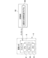
- the CPU 37 includes a subject image detection unit 37A, an image position determination unit 37B, a zoom determination unit 37C, a first deviation amount calculation unit 37D, a second deviation amount calculation unit 37E, a rotation amount derivation unit 37F, and a rotation completion determination. It operates as a unit 37G and a control unit 37H.
- the subject image detection unit 37A and the image position determination unit 37B are examples of the "detection unit” in the technique of the present disclosure.
- the control unit 37H is an example of a “control unit” in the technique of the present disclosure.
- the CPU 37 is an example of the "processor” according to the technique of the present disclosure
- the memory 35 is an example of the "memory” according to the technique of the present disclosure.
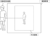
- the subject image detection unit 37A acquires an captured image for one frame from the image memory 32. Then, the subject image detection unit 37A detects the target subject image in the captured image acquired from the image memory 32. Further, the subject image detection unit 37A detects the position of the subject image when the target subject image is detected. The detection of the subject image position by the subject image detection unit 37A is performed even when the swivel mechanism 16 is activated, as will be described later.
- the image position determination unit 37B determines whether or not the subject image position detected by the subject image detection unit 37A is within the central region in the captured image. As an example, as shown in FIGS. 7A and 7B, when the target subject is included in the imaging region, the subject image position is within the central region in the captured image, but as an example, as shown in FIGS. 8A and 8B, When the surveillance camera 10 is swiveled by the swivel mechanism 16 or the target subject itself moves and the target subject deviates from the imaging region, the subject image position is not in the central region.
- the determination by the image position determination unit 37B is affirmed.
- "existence" means a mode in which at least a part of the target subject image covers the central region. That is, if at least a part of the target subject image covers the central region, the image position determination unit 37B determines that the image is "existing".
- an image showing a specific portion included in the subject image for example, when the target subject is a person, the face of the person can be mentioned.
- An image recognition function such as a so-called face recognition function is mounted on the surveillance camera 10, and when an image indicating a specific part is detected by the image recognition function, the target subject image exists in the central region by the image position determination unit 37B. It may be determined that the image is correct.
- the central region is an example of a "specific position" according to the technique of the present disclosure.
- the zoom determination unit 37C detects the focal length of the surveillance camera 10 when the image position determination unit 37B determines that the subject image position is within the central region. Then, the zoom determination unit 37C determines whether or not the focal length has become longer from the change in the focal length (for example, the change in the focal length from a few frames ago to the current focal length). When the focal length becomes long, the angle of view taken by the surveillance camera 10 becomes narrower than before it becomes longer.
- FIG. 9 shows an example. As shown, the target subject image shifts from the central region. In the example shown in FIG. 9, the mode in which the target subject image deviates from the captured image is shown.
- the first deviation amount calculation unit 37D calculates the first deviation amount when the zoom determination unit 37C determines that the focal length has become longer.
- the first deviation amount is an amount indicating the deviation (relative position difference) of the subject image position with respect to the central region in the captured image, and is a vector having two values in the pitch axis PA direction and the yaw axis YA direction. ..
- Examples of the first deviation amount include the deviation amount between the center of the target subject image and the center of the central region.
- the center of the target subject image can be obtained as two values of the center coordinate of the target subject image in the pitch axis PA direction and the center seat amount in the yaw axis YA direction.
- the first deviation amount is an example of the "offset amount" according to the technique of the present disclosure.
- the swivel amount table 42A is stored in the storage 36.
- the subject image position detected by the subject image detection unit 37A may deviate from the central region in the captured image.
- the position of the subject image can be moved in the captured image to bring it closer to the central region.
- the turning amount table 42A is information in which the deviation amount between the subject image position and the central region and the turning amount of the surveillance camera 10 by the turning mechanism 16 are associated with each other, and is included in the captured image. It is used when the position of the subject image is brought closer to the central region.
- the turning amount is determined according to each of the pitch axis PA direction and the yaw axis YA direction.
- the turning amount specified in the turning amount table 42A for example, a turning amount derived in advance as an optimum turning amount for eliminating the deviation amount by a sensory test using an actual machine and / or a computer simulation or the like is used. Can be mentioned.
- the swivel amount table 42A is illustrated here, the technique of the present disclosure is not limited to this, and the deviation amount is independent in combination with the swivel amount table 42A or in place of the swivel amount table 42A.
- An arithmetic expression for deriving the turning amount may be applied with the turning amount as a variable and the turning amount as the dependent variable.
- the turning amount deriving unit 37F acquires the turning amount table 42A from the storage 36. Further, the turning amount deriving unit 37F acquires the first deviation amount from the first deviation amount calculation unit 37D. Then, the turning amount deriving unit 37F derives the turning amount corresponding to the first deviation amount from the turning amount table 42A.
- the turning amount is also a vector having two values in the pitch direction and the yaw direction.
- the swivel amount deriving unit 37F outputs the derived swivel amount to the control unit 37H.
- the control unit 37H operates the swivel mechanism 16 based on the swivel amount derived by the swivel amount derivation unit 37F.
- the swivel mechanism 16 is operated based on the swivel amount determined according to the ratios in the pitch direction and the yaw direction of the swivel amount derived by the swivel amount lead-out unit 37F, and the swivel mechanism 16 is operated.
- the surveillance camera 10 is swiveled by. By turning the surveillance camera 10, the imaging range is changed so that the subject image position approaches the central region in the captured image.
- control unit 37H When the rotation of the surveillance camera 10 by the rotation mechanism 16 is completed, the control unit 37H outputs a completion signal indicating that the rotation of the surveillance camera 10 by the rotation mechanism 16 is completed to the rotation completion determination unit 37G.
- the turning completion determination unit 37G determines whether or not the turning of the surveillance camera 10 by the turning mechanism 16 has been completed.
- the turning completion determination unit 37G determines that the turning of the surveillance camera 10 by the turning mechanism 16 is completed.
- the image position determination unit 37B determines whether or not the subject image position is within the central region.
- the second deviation amount calculation unit 37E calculates the second deviation amount when the image position determination unit 37B determines that the subject image position is not within the central region.
- the second deviation amount is an amount indicating the deviation (difference in relative position) of the subject image position with respect to the central region, and is a vector having two values in the pitch axis PA direction and the yaw axis YA direction.
- the second amount of deviation includes, for example, the amount of deviation between the center of the target subject image and the center of the central region.
- the center of the target subject image can be obtained as two values of the center coordinate of the target subject image in the pitch axis PA direction and the center seat amount in the yaw axis YA direction.
- the second deviation amount is an example of the "offset amount" according to the technique of the present disclosure. In the following, for convenience of explanation, when it is not necessary to distinguish between the first deviation amount and the second deviation amount, it is also referred to as an “offset amount”.
- the position of the subject image may deviate from the central region in the captured image. Then, by turning the surveillance camera 10 by the turning mechanism 16, the position of the captured image can be aligned with the captured image. However, the accuracy of this alignment decreases as the focal length is multiplied to the telephoto side. In this way, the amount of offset in the captured image increases due to the scaling of the focal length to the telephoto side.
- the control unit 37 operates the lens-side shake correction mechanism 29 according to the offset amount to move the anti-vibration lens 15B1 in the two-dimensional plane of the anti-vibration lens.
- the captured images transmitted from the surveillance camera 10 are sequentially input to the control device 60 of the management device 11. Then, under the control of the control device 60, the display 13 displays the captured images sequentially input to the control device 60 as, for example, a live view image.
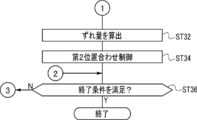
- FIGS. 12A and 12B show an example of the flow of the alignment control process executed by the CPU 37.
- the alignment control is a control including a control of aligning the subject image position detected by the subject image detection unit 37A with the central region by operating the lens side shake correction mechanism 29.
- the flow of the alignment control process shown in FIGS. 12A and 12B is an example of the "imaging support method" according to the technique of the present disclosure.
- step ST10 the subject image detection unit 37A determines whether or not a new captured image is stored in the image memory 32. If the new captured image is not stored in the image memory 32 in step ST10, the determination is denied and the alignment control process shifts to step ST36 shown in FIG. 12B. When a new captured image is stored in the image memory 32 in step ST10, the determination is affirmed and the alignment control process shifts to step ST12.
- step ST12 the subject image detection unit 37A acquires the captured image. Then, the alignment control process shifts to step ST14.
- step ST14 the subject image detection unit 37A executes the subject image detection process.
- the subject image detection process refers to a process of detecting a target subject image from the captured image.
- the subject image detection unit 37A determines whether or not the target subject image is detected in the captured image by executing the subject image detection process. If the subject image is not detected in the captured image in step ST16, the determination is denied and the alignment control process proceeds to step ST36 shown in FIG. 13B. When the target subject image is detected in the captured image by executing the subject image detection process in step ST16, the determination is affirmed and the alignment control process shifts to step ST18.
- the subject image detection unit 37A detects the subject image position from the captured image. For example, in the subject image detection unit 37A, when the target subject image is in a standing position and is a front-view person image, the crown of the person image is set as the upper end of the target subject image, and the toes of the person image are set as the upper end of the person image. The position of the subject image is detected as the lower end of the target subject image. Further, the subject image detection unit 37A detects the right shoulder portion or the right arm portion of the person image as the right end portion of the target subject image, and the left shoulder portion or the left arm portion of the person image as the left end portion of the target subject image.
- the image position determination unit 37B determines whether or not the subject image position is within the central region. If the subject image position is within the central region in step ST20, the determination is affirmed, and the alignment control process shifts to step ST22. If the subject image position is not within the central region in step ST20, the determination is denied, and the alignment control process shifts to step ST32 shown in FIG. 13B.
- step ST32 shown in FIG. 13B the second deviation amount calculation unit 37E calculates the second deviation amount.
- the control unit 37H performs the second alignment control by operating the lens side shake correction mechanism 29 according to the second deviation amount calculated in the step ST32.
- the lens side shake correction mechanism 29 As shown in FIG. 13 as an example, the subject image position outside the central region of FIG. 13 before the lens side shake correction mechanism 29 is operated is changed to the lens side shake. After the correction mechanism 29 is operated, it is housed in the central region.
- step ST22 shown in FIG. 12A the zoom determination unit 37C determines whether or not the focal length of the surveillance camera 10 has become longer. If the focal length is not long in step ST22, the determination is denied and the alignment control process proceeds to step ST36 shown in FIG. 12B. When the focal length becomes long in step ST22, the determination is affirmed, and the alignment control process shifts to step ST24.
- step ST24 the first deviation amount calculation unit 37D calculates the first deviation amount. Then, the alignment control process shifts to step ST26.
- step ST26 the turning amount deriving unit 37F derives the turning amount corresponding to the first deviation amount derived in step ST24 from the turning amount table 42A. Then, the alignment control process shifts to step ST28.
- step ST28 the control unit 37H performs the first alignment control by operating the swivel mechanism 16 based on the swivel amount derived in step ST26.
- the control unit 37H operates the swivel mechanism 16 to move the subject image position toward the central region.
- step ST30 the turning completion determination unit 37G determines whether or not the turning is completed. If the turning is not completed in step ST30, the determination is denied, and the alignment control process re-determines step ST30. When the turning is completed in step ST30, the determination is affirmed, and the alignment control process shifts to step ST20.
- step ST36 shown in FIG. 12B the control unit 37H determines whether or not the condition for terminating the alignment control process (hereinafter, referred to as "end condition") is satisfied.
- the end condition include a condition that the reception device 62 has received an instruction to end the alignment control process. If the end condition is not satisfied in step ST36, the determination is denied and the alignment control process proceeds to step ST10 shown in FIG. 12A. If the end condition is satisfied in step ST36, the determination is affirmed and the alignment control process ends.
- the accuracy of alignment by turning the surveillance camera 10 is often lower than the accuracy of alignment by operating the lens side shake correction mechanism 29.
- the subject image position position indicated by the alternate long and short dash line
- the subject image position position indicated by the alternate long and short dash line
- the central region moves to the right side of the captured image. It may not be located in the central area because it is (the position shown by the solid line).
- the turning angle due to the operation of the turning mechanism 16 is set to 1 degree (60 minutes) by the degree method and the turning mechanism 16 is operated, the turning angle may be 57 minutes or 63 minutes. There are variations such as the turning angle of. Therefore, there is a limit to the accuracy when the subject image position is moved to the central region by the operation of the turning mechanism 16.
- the alignment can be performed with higher accuracy than the case where the turning mechanism 16 is operated. That is, the lens side shake correction mechanism 29 is operated to perform the second alignment control, so that the subject image position can be aligned with the central region in the captured image.
- the variation in the turning angle is adjusted so as to be less than half of the angle of view on the telephoto side of the scaling mechanism. Moreover, the variation in the turning angle is adjusted so as to be less than the offset amount. Therefore, even if the rotation stop position of the surveillance camera 10 by the rotation mechanism 16 varies while the magnification change mechanism is on the telephoto side, the subject image position is centered in the captured image by the operation of the lens side shake correction mechanism 29. Can be adapted to the area.
- the subject image position may not exist in the central region due to the rotation of the surveillance camera 10.
- the lens side shake correction mechanism 29 is operated according to the second deviation amount by the alignment control process. Therefore, even if a situation occurs in which the subject image position is not located in the central region even though the subject image position is moved into the central region by the operation of the swivel mechanism 16, the subsequent operation of the lens side shake correction mechanism 29 causes the drawing. As shown in 11, the subject image position can be within the central region.
- the surveillance camera 10 includes an image pickup support device 44.
- the image pickup support device 44 when the focal length of the surveillance camera 10 becomes long, that is, when the magnification is changed to the telephoto side, even if the subject image position deviates from the central region due to the change, the control unit 37H However, the alignment control is performed so that the position of the subject image is aligned with the central region. In this way, even if the subject image position shifts with respect to the captured image due to the scaling to the telephoto side, the subject image position is set to the central region in the captured image (an example of the "specific position" according to the technique of the present disclosure). Can be adjusted to.
- the surveillance camera 10 has a lens side shake correction mechanism 29.
- the lens-side shake correction mechanism 29 is a mechanism for correcting shake caused by vibration given to the surveillance camera 10.
- the alignment control includes a control for aligning the subject image position detected by the subject image detection unit 37A with the central region by operating the lens side shake correction mechanism 29. In this way, the alignment control is performed by using the lens side shake correction mechanism 29, which is a mechanism for correcting the shake caused by the vibration given to the surveillance camera 10. Therefore, as compared with the case where the surveillance camera 10 is equipped with a mechanism used only for the alignment control, it is possible to suppress an increase in the number of parts required for the alignment control.
- the alignment control by the image pickup support device 44 includes the control of aligning the subject image position with the central region by operating the swivel mechanism 16. Since the existing swivel mechanism 16 is used as compared with the case where a mechanism used only for the alignment control is newly installed instead of the swivel mechanism 16, it is possible to suppress an increase in the number of parts required for the alignment control.
- the control unit 37H operates at least one of the lens side shake correction mechanism 29 and the turning mechanism 16 according to these offset amounts.
- the alignment control can be performed by operating both the lens side shake correction mechanism 29 and the turning mechanism 16. Therefore, it is possible to realize highly accurate alignment of the subject image position with respect to the central region as compared with the case where only the lens side shake correction mechanism 29 or the turning mechanism 16 is operated for the alignment control.
- the alignment control includes a first alignment control performed by operating the swivel mechanism 16 and a second alignment control performed by operating the lens side shake correction mechanism 29.
- the alignment accuracy of the second alignment control is higher than the alignment accuracy of the first alignment control.
- the control unit 37H first performs the alignment control with relatively low accuracy and then with relatively high accuracy by performing the first alignment control and then the second alignment control. Therefore, for example, as compared with the case where the alignment control is performed using only the turning mechanism 16, it is possible to realize higher accuracy in the alignment of the subject image position with respect to the central region.
- the rotation mechanism 16 operates to make a rough adjustment to the subject image position, and then the lens side shake correction mechanism 29 operates to make a fine adjustment to the subject image position. It is possible to realize high accuracy of the combined control.
- the surveillance camera 10 has a function (optical zoom function) for changing the focal length.
- the position of the subject image that was in the central region before scaling may deviate from the central region after scaling, and may also deviate from the captured image.
- the subject image position can be relatively moved toward the captured image by operating the swivel mechanism 16. Then, in a state where the subject image position is in the captured image, the subject image position can be accurately stored in the central region by operating the lens side shake correction mechanism 29.
- the focal length of the surveillance camera 10 is once scaled to the wide-angle side to widen the angle of view, thereby obtaining a situation in which the subject image position exists in the captured image. You may do so. Then, with the focal length of the surveillance camera 10 set to the wide-angle side, the swivel mechanism 16 is operated so that the subject image position moves toward the central region, and then the focal length of the surveillance camera 10 is set to the telephoto side again. (For example, change to the value before scaling to the wide-angle side).
- the position of the subject image in the captured image may shift from the central region due to the rotation of the surveillance camera 10 by the rotation mechanism 16. Then, the offset amount of the subject image position increases relatively by increasing the focal length (magnifying to the telephoto side).
- the lens side shake correction mechanism 29 adjusts the subject image position to the central region. Therefore, if the subject image position is in the captured image, the alignment can be performed regardless of the offset amount. Moreover, the accuracy (alignment accuracy) when aligning the subject image position with the central region is lowered by increasing the focal length (magnifying to the telephoto side).
- the alignment can be performed by operating at least one of the lens side shake correction mechanism 29, the image sensor shake correction mechanism 45, and the electronic shake correction unit 33.
- the central area is an example of a "specific position" in the technology of the present disclosure.
- the "specific position” is not limited to the central region of the captured image, and may be a position deviated from the center of the captured image in the pitch axis PA direction and the yaw axis YA direction.
- the vibration is corrected by moving the anti-vibration lens 15B1. Therefore, the vibration can be corrected within the range of motion of the anti-vibration lens 15B1 and the position of the subject image can be adjusted to the central region.
- the second embodiment will be described.
- the same elements and members as those in the first embodiment are designated by the same reference numerals as those in the first embodiment, and detailed description thereof will be omitted.
- the overall configuration of the imaging camera which is an example of the imaging device of the second embodiment, is the same as that of the surveillance camera 10 of the first embodiment, and thus the illustration is omitted.
- the shake correction mechanism operated when the control unit 37H performs the alignment control is the image sensor side shake correction mechanism 45.
- the shake correction mechanism operated in the state where the alignment control process is in step ST34 is the image sensor side shake correction mechanism 45 in the second embodiment. ..
- the image sensor side shake correction mechanism 45 is used for the alignment control, and the lens side shake correction mechanism 29 is not used. Therefore, it is possible to use the lens side shake correction mechanism 29 for the shake correction of the surveillance camera 10 during the alignment control.
- the lens side shake correction mechanism 29 is used for the alignment control, and the image sensor side shake correction mechanism 45 and the electronic shake correction unit 33 are not used. Therefore, during the alignment control, at least one of the image sensor side shake correction mechanism 45 and the electronic shake correction unit 33 can be used to correct the shake of the surveillance camera 10.
- the third embodiment will be described.
- the same elements and members as those in the first embodiment are designated by the same reference numerals as those in the first embodiment, and detailed description thereof will be omitted.
- the overall configuration of the imaging camera which is an example of the imaging device of the third embodiment, is the same as that of the surveillance camera 10 of the first embodiment, and thus the illustration is omitted.
- the electronic runout correction unit 33 is operated when the control unit 37H performs alignment control.
- the alignment control process is executed by the operation of the electronic runout correction unit 33 in the state where the alignment control process is in step ST34.
- the electronic shake correction unit 33 is used for the alignment control, and the lens side shake correction mechanism 29 and the image sensor side shake correction mechanism 45 are not used. Therefore, during the alignment control, at least one of the lens side shake correction mechanism 29 and the image sensor side shake correction mechanism 45 can be used to correct the shake of the surveillance camera 10.
- the lens side shake correction mechanism 29 is used for the alignment control, and the image sensor side shake correction mechanism 45 is not used. Therefore, it is possible to use the image sensor side shake correction mechanism 45 for the shake correction of the surveillance camera 10 during the alignment control.
- Each of the first embodiment, the second embodiment, and the third embodiment has a lens side shake correction mechanism 29, an image sensor side shake correction mechanism 45, and an electronic device shake correction unit 33. Therefore, when performing the alignment control process, by operating at least one of these, it is possible to align the subject image position with the central region in the alignment control process.
- the alignment and the shake correction may be executed by operating both the lens side shake correction mechanism 29 and the image sensor side shake correction mechanism 45.
- the alignment and the vibration correction can be performed within the range of motion of each of the anti-vibration lens 15B1 and the image sensor 25.
- the shake that could not be corrected due to the movement of the vibration-proof lens 15B1 being restricted by the range of motion of the vibration-proof lens 15B1 is moved by another shake correction mechanism or a shake correction unit, for example, the image sensor 25. It becomes possible to correct it.
- the surveillance camera 10 detects the amount of runout in each of the pitch axis PA direction and the yaw axis YA. Therefore, the runout can be corrected with higher accuracy than the case where the runout is corrected by using only the runout amount in one axial direction.
- the alignment control processing program 36A is stored in the storage 36 of the surveillance camera 10, and the CPU 37 of the surveillance camera executes the alignment control processing program 36A in the memory 35.
- the disclosed technology is not limited to this.
- the alignment control processing program 36A may be stored in the storage 60B of the management device 11, and the CPU 60A of the management device 11 may execute the alignment control processing program 36A in the memory 60C.
- the alignment control processing program 36A may be stored in the storage medium 100 which is a non-temporary storage medium.
- the alignment control processing program 36A stored in the storage medium 100 is installed in the computer 19, and the CPU 37 executes the alignment control processing described above according to the alignment control processing program 36A. ..
- the CPU 37 is a single CPU, but the technique of the present disclosure is not limited to this, and a plurality of CPUs may be adopted.
- An example of the storage medium 100 is an arbitrary portable storage medium such as an SSD or a USB memory.
- the alignment control processing program 36A is stored in a storage unit of another computer or server device connected to the computer 19 via a communication network (not shown), and in response to the above-mentioned request of the surveillance camera 10.
- the alignment control processing program 36A may be downloaded to the computer 19.
- the downloaded alignment control processing program 36A is executed by the CPU 37 of the computer 19.
- the alignment control processing program 36A is installed in the computer 19 of the surveillance camera 10
- the technique of the present disclosure is not limited to this, and the control of the management device 11 is controlled.
- the alignment control processing program 36A may be installed in the device 60.
- the CPU 60A executes the above-described alignment control process according to the alignment control process program 36A.
- the alignment control process may be distributed between the surveillance camera 10 and the management device 11. For example, the first alignment control (see step ST28 shown in FIG. 12A) is executed by the CPU 60A of the management device 11, and the second alignment control (see step ST34 shown in FIG. 12B) is executed by the CPU 37 of the surveillance camera 10. You may do so.
- the unit 37G and the control unit 37H have been described with reference to an example of a form realized by a software configuration by a computer 19, the technique of the present disclosure is not limited thereto.
- 37H may be implemented by devices including, for example, ASICs, FPGAs, and / or PLDs. Further, the subject image detection unit 37A, the image position determination unit 37B, the zoom determination unit 37C, the first deviation amount calculation unit 37D, the second deviation amount calculation unit 37E, the turning amount derivation unit 37F, the turning completion determination unit 37G, and the control unit. 37H may be realized by a combination of a hardware configuration and a software configuration.
- the processor As the hardware resource for executing the above alignment control process, the following various processors can be used.
- the processor include, as described above, software, that is, a CPU, which is a general-purpose processor that functions as a hardware resource for executing alignment control processing by executing a program.
- examples of the processor include a dedicated electric circuit which is a processor having a circuit configuration specially designed for executing a specific process such as FPGA, PLD, or ASIC.
- a memory is built in or connected to each processor, and each processor executes the alignment control process by using the memory.
- the hardware resource that executes the alignment control process may be composed of one of these various processors, or a combination of two or more processors of the same type or different types (for example, a combination of a plurality of FPGAs, etc.). Alternatively, it may be composed of a combination of a CPU and an FPGA). Further, the hardware resource for executing the alignment control process may be one processor.
- one processor is configured by a combination of one or more CPUs and software, and this processor is a control unit 37, a subject image detection unit 37A, and a zoom determination unit 37C.
- this processor is a control unit 37, a subject image detection unit 37A, and a zoom determination unit 37C.
- SoC there is a form in which a processor that realizes the functions of the entire system including a plurality of hardware resources that execute alignment control processing with one IC chip is used.
- each of the processes of the control unit 37, the subject image detection unit 37A, and the zoom determination unit 37C is realized by using one or more of the above-mentioned various processors as hardware resources.
- the surveillance camera 10 is mentioned as an example of the imaging device according to the technique of the present disclosure, but the technique of the present disclosure is not limited to this.
- the technology of the present disclosure may be applied to various electronic devices such as a portable interchangeable lens camera, a portable fixed lens camera, a personal computer, a smart device, or a wearable terminal device. Is applicable. Even with these electronic devices, the same operations and effects as those of the surveillance camera 10 described in each of the above embodiments can be obtained.
- a and / or B is synonymous with "at least one of A and B". That is, “A and / or B” means that it may be only A, only B, or a combination of A and B. Further, in the present specification, when three or more matters are connected and expressed by "and / or", the same concept as “A and / or B" is applied.
- the processor Includes memory built into or connected to the processor
- the above processor Detects the subject image position of the target subject image indicating the target subject in the captured image obtained by capturing the imaging area including the target subject by the operation of the swivel mechanism that rotates the image pickup device having the variable magnification mechanism. And Information processing that adjusts the detected subject image position to a specific position in the captured image of the captured image obtained by imaging with the image pickup device as the magnification changes to the telephoto side by the scaling mechanism. apparatus.
Landscapes
- Engineering & Computer Science (AREA)
- Physics & Mathematics (AREA)
- Multimedia (AREA)
- Signal Processing (AREA)
- General Physics & Mathematics (AREA)
- General Engineering & Computer Science (AREA)
- Mechanical Engineering (AREA)
- Optics & Photonics (AREA)
- Human Computer Interaction (AREA)
- Studio Devices (AREA)
- Adjustment Of Camera Lenses (AREA)
- Accessories Of Cameras (AREA)
Priority Applications (5)
| Application Number | Priority Date | Filing Date | Title |
|---|---|---|---|
| JP2021553466A JP7212175B2 (ja) | 2019-10-29 | 2020-10-20 | 撮像支援装置、撮像支援システム、撮像システム、撮像支援方法、及びプログラム |
| CN202080075109.5A CN114641985B (zh) | 2019-10-29 | 2020-10-20 | 摄像支援装置、摄像支援系统、摄像系统、摄像支援方法及存储介质 |
| US17/659,170 US11678055B2 (en) | 2019-10-29 | 2022-04-13 | Imaging support device, imaging support system, imaging system, imaging support method, and program |
| JP2023003268A JP7499894B2 (ja) | 2019-10-29 | 2023-01-12 | 撮像支援装置、撮像支援システム、撮像システム、撮像支援方法、及びプログラム |
| US18/310,496 US11979663B2 (en) | 2019-10-29 | 2023-05-01 | Imaging support device, imaging support system, imaging system, imaging support method, and program |
Applications Claiming Priority (2)
| Application Number | Priority Date | Filing Date | Title |
|---|---|---|---|
| JP2019-196680 | 2019-10-29 | ||
| JP2019196680 | 2019-10-29 |
Related Child Applications (1)
| Application Number | Title | Priority Date | Filing Date |
|---|---|---|---|
| US17/659,170 Continuation US11678055B2 (en) | 2019-10-29 | 2022-04-13 | Imaging support device, imaging support system, imaging system, imaging support method, and program |
Publications (1)
| Publication Number | Publication Date |
|---|---|
| WO2021085246A1 true WO2021085246A1 (ja) | 2021-05-06 |
Family
ID=75714491
Family Applications (1)
| Application Number | Title | Priority Date | Filing Date |
|---|---|---|---|
| PCT/JP2020/039424 Ceased WO2021085246A1 (ja) | 2019-10-29 | 2020-10-20 | 撮像支援装置、撮像支援システム、撮像システム、撮像支援方法、及びプログラム |
Country Status (4)
| Country | Link |
|---|---|
| US (2) | US11678055B2 (https=) |
| JP (2) | JP7212175B2 (https=) |
| CN (1) | CN114641985B (https=) |
| WO (1) | WO2021085246A1 (https=) |
Cited By (1)
| Publication number | Priority date | Publication date | Assignee | Title |
|---|---|---|---|---|
| US11979663B2 (en) | 2019-10-29 | 2024-05-07 | Fujifilm Corporation | Imaging support device, imaging support system, imaging system, imaging support method, and program |
Families Citing this family (5)
| Publication number | Priority date | Publication date | Assignee | Title |
|---|---|---|---|---|
| JP7580955B2 (ja) * | 2020-07-02 | 2024-11-12 | キヤノン株式会社 | 撮像装置、方法、プログラム及び記憶媒体 |
| JP7651349B2 (ja) * | 2021-03-30 | 2025-03-26 | キヤノン株式会社 | 撮像装置 |
| CN116951243B (zh) * | 2023-08-02 | 2025-10-28 | 史万庆 | 多功能机箱底托 |
| US12593129B2 (en) * | 2023-08-18 | 2026-03-31 | Canon U.S.A., Inc. | Apparatus and methods for adjusting zoom of a PTZ camera |
| WO2026010090A1 (ko) * | 2024-07-01 | 2026-01-08 | 삼성전자 주식회사 | 전자 장치 및 전자 장치의 출력 프레임을 보정하는 방법 |
Citations (2)
| Publication number | Priority date | Publication date | Assignee | Title |
|---|---|---|---|---|
| JPH06217187A (ja) * | 1992-10-14 | 1994-08-05 | Mitsubishi Electric Corp | 撮像装置,動きベクトル検出装置及び画像揺れ補正装置 |
| JP2016028539A (ja) * | 2014-07-04 | 2016-02-25 | パナソニックIpマネジメント株式会社 | 撮像装置 |
Family Cites Families (9)
| Publication number | Priority date | Publication date | Assignee | Title |
|---|---|---|---|---|
| US5835641A (en) * | 1992-10-14 | 1998-11-10 | Mitsubishi Denki Kabushiki Kaisha | Image pick-up apparatus for detecting and enlarging registered objects |
| JP2015037248A (ja) * | 2013-08-13 | 2015-02-23 | キヤノン株式会社 | 撮像装置、撮像装置の制御方法、プログラム、および、記憶媒体 |
| JP6395381B2 (ja) * | 2014-01-08 | 2018-09-26 | キヤノン株式会社 | 撮像装置及びその制御方法 |
| JP2016035543A (ja) | 2014-08-04 | 2016-03-17 | オリンパス株式会社 | 撮像装置及びその像ブレ補正方法 |
| EP3214832B1 (en) * | 2014-10-31 | 2019-11-27 | Fujifilm Corporation | Imaging device and method for recognizing target object |
| JP7020651B2 (ja) * | 2017-10-03 | 2022-02-16 | 株式会社Mirai Eye | 調節眼内レンズ |
| JP7076988B2 (ja) * | 2017-11-28 | 2022-05-30 | キヤノン株式会社 | 撮像装置および制御方法 |
| JP7212175B2 (ja) | 2019-10-29 | 2023-01-24 | 富士フイルム株式会社 | 撮像支援装置、撮像支援システム、撮像システム、撮像支援方法、及びプログラム |
| JP7393245B2 (ja) * | 2020-02-26 | 2023-12-06 | キヤノン株式会社 | 撮像装置及びその制御方法、プログラム、記憶媒体 |
-
2020
- 2020-10-20 JP JP2021553466A patent/JP7212175B2/ja active Active
- 2020-10-20 CN CN202080075109.5A patent/CN114641985B/zh active Active
- 2020-10-20 WO PCT/JP2020/039424 patent/WO2021085246A1/ja not_active Ceased
-
2022
- 2022-04-13 US US17/659,170 patent/US11678055B2/en active Active
-
2023
- 2023-01-12 JP JP2023003268A patent/JP7499894B2/ja active Active
- 2023-05-01 US US18/310,496 patent/US11979663B2/en active Active
Patent Citations (2)
| Publication number | Priority date | Publication date | Assignee | Title |
|---|---|---|---|---|
| JPH06217187A (ja) * | 1992-10-14 | 1994-08-05 | Mitsubishi Electric Corp | 撮像装置,動きベクトル検出装置及び画像揺れ補正装置 |
| JP2016028539A (ja) * | 2014-07-04 | 2016-02-25 | パナソニックIpマネジメント株式会社 | 撮像装置 |
Cited By (1)
| Publication number | Priority date | Publication date | Assignee | Title |
|---|---|---|---|---|
| US11979663B2 (en) | 2019-10-29 | 2024-05-07 | Fujifilm Corporation | Imaging support device, imaging support system, imaging system, imaging support method, and program |
Also Published As
| Publication number | Publication date |
|---|---|
| US20230276128A1 (en) | 2023-08-31 |
| US11678055B2 (en) | 2023-06-13 |
| JP7212175B2 (ja) | 2023-01-24 |
| JP7499894B2 (ja) | 2024-06-14 |
| CN114641985B (zh) | 2024-05-31 |
| CN114641985A (zh) | 2022-06-17 |
| US20220239818A1 (en) | 2022-07-28 |
| JP2023052365A (ja) | 2023-04-11 |
| JPWO2021085246A1 (https=) | 2021-05-06 |
| US11979663B2 (en) | 2024-05-07 |
Similar Documents
| Publication | Publication Date | Title |
|---|---|---|
| JP7499894B2 (ja) | 撮像支援装置、撮像支援システム、撮像システム、撮像支援方法、及びプログラム | |
| JP7456043B2 (ja) | 撮像支援装置、撮像支援システム、撮像システム、撮像支援方法、及びプログラム | |
| JP7612725B2 (ja) | 撮像支援装置、撮像装置、撮像システム、撮像支援システム、撮像支援方法、及びプログラム | |
| US11930280B2 (en) | Imaging support device, imaging system, imaging support method, and program | |
| JPWO2011129036A1 (ja) | 撮像装置および集積回路 | |
| US20220286613A1 (en) | Imaging support device, imaging apparatus, imaging system, imaging support method, and program | |
| US11917297B2 (en) | Imaging support device, imaging apparatus, imaging system, imaging support system, imaging support method, and program | |
| JP6257288B2 (ja) | 撮像装置およびその制御方法 | |
| WO2014115197A1 (ja) | 撮像装置、検出装置 | |
| WO2025047473A1 (ja) | 撮像システム、撮像装置、制御装置、制御方法、及び制御プログラム |
Legal Events
| Date | Code | Title | Description |
|---|---|---|---|
| 121 | Ep: the epo has been informed by wipo that ep was designated in this application |
Ref document number: 20881822 Country of ref document: EP Kind code of ref document: A1 |
|
| ENP | Entry into the national phase |
Ref document number: 2021553466 Country of ref document: JP Kind code of ref document: A |
|
| NENP | Non-entry into the national phase |
Ref country code: DE |
|
| 122 | Ep: pct application non-entry in european phase |
Ref document number: 20881822 Country of ref document: EP Kind code of ref document: A1 |