WO2021084744A1 - 冷凍サイクル装置 - Google Patents
冷凍サイクル装置 Download PDFInfo
- Publication number
- WO2021084744A1 WO2021084744A1 PCT/JP2019/043100 JP2019043100W WO2021084744A1 WO 2021084744 A1 WO2021084744 A1 WO 2021084744A1 JP 2019043100 W JP2019043100 W JP 2019043100W WO 2021084744 A1 WO2021084744 A1 WO 2021084744A1
- Authority
- WO
- WIPO (PCT)
- Prior art keywords
- heat exchanger
- refrigerant
- expansion valve
- pressure
- injection port
- Prior art date
- Legal status (The legal status is an assumption and is not a legal conclusion. Google has not performed a legal analysis and makes no representation as to the accuracy of the status listed.)
- Ceased
Links
Images


Classifications
-
- F—MECHANICAL ENGINEERING; LIGHTING; HEATING; WEAPONS; BLASTING
- F25—REFRIGERATION OR COOLING; COMBINED HEATING AND REFRIGERATION SYSTEMS; HEAT PUMP SYSTEMS; MANUFACTURE OR STORAGE OF ICE; LIQUEFACTION SOLIDIFICATION OF GASES
- F25B—REFRIGERATION MACHINES, PLANTS OR SYSTEMS; COMBINED HEATING AND REFRIGERATION SYSTEMS; HEAT PUMP SYSTEMS
- F25B1/00—Compression machines, plants or systems with non-reversible cycle
Definitions
- the present invention relates to a refrigeration cycle apparatus including a compressor having an injection port.
- Patent Document 1 discloses an air conditioner in which two injection ports communicate with two compression mechanisms of a compressor. According to the air conditioner, it is possible to secure both the heat dissipation amount of the refrigerant in the condenser and the heat absorption amount of the refrigerant in the evaporator.
- An intermediate pressure refrigerant that is greater than the pressure of the refrigerant sucked into the compressor and smaller than the pressure of the refrigerant discharged from the compressor is allowed to flow in from the injection port during the process of compressing the refrigerant by the compressor (intermediate). It is known that the temperature (discharge temperature) of the refrigerant discharged from the compressor can be suppressed by pressure injection). However, if the temperature of the refrigerant exceeds the upper limit of the compressor in the compression process prior to the intermediate pressure injection, the reliability of the compressor may decrease even if the discharge temperature is suppressed by the intermediate pressure injection. On the other hand, excessive cooling by intermediate pressure injection deteriorates the performance of the refrigeration cycle device. In the air conditioner disclosed in Patent Document 1, both maintenance of reliability of the compressor and suppression of performance deterioration of the refrigeration cycle apparatus are not considered.
- the present invention has been made to solve the above-mentioned problems, and an object of the present invention is to suppress deterioration of the performance of the refrigeration cycle apparatus while maintaining the reliability of the compressor.
- the refrigeration cycle device includes a compressor, a first heat exchanger, a second heat exchanger, a third heat exchanger, a fourth heat exchanger, a first expansion valve, a second expansion valve, and a first. 3 It is provided with an expansion valve.
- the compressor includes a suction port, a discharge port, a compression mechanism, a first injection port, and a second injection port.
- the compression mechanism compresses the refrigerant from the suction port and discharges it from the discharge port.
- the first injection port communicates with the compression mechanism.
- the second injection port communicates with the compression mechanism.
- the refrigerant circulates in the order of the discharge port, the first heat exchanger, the second heat exchanger, the third heat exchanger, the first expansion valve, the fourth heat exchanger, and the intake port.
- the refrigerant circulates in the order of the discharge port, the first heat exchanger, the second heat exchanger, the third heat exchanger, the second expansion valve, the third heat exchanger, and the first injection port.
- the refrigerant circulates in the order of the discharge port, the first heat exchanger, the second heat exchanger, the third expansion valve, the second heat exchanger, and the second injection port.
- the first pressure of the refrigerant at the first injection port is higher than the suction pressure of the refrigerant at the suction port and lower than the geometric mean of the discharge pressure and suction pressure of the refrigerant at the discharge port.
- the second pressure of the refrigerant at the second injection port is higher than the first pressure and lower than the discharge pressure.
- the first pressure of the refrigerant at the first injection port is lower than the geometric mean of the discharge pressure and the suction pressure, and the second pressure of the refrigerant at the second injection port is higher than the first pressure.
- FIG. It is a functional block diagram which shows the structure of the refrigeration cycle apparatus 100 which concerns on Embodiment 1.
- FIG. It is a functional block diagram which shows the structure of the control device 10 of FIG. It is a figure which shows the compression process of the compression mechanism 60 of FIG. It is a flowchart which shows the flow of the control process of the expansion valve 52 performed by the control device 10 of FIG. It is a flowchart which shows the flow of the control process of the expansion valve 53 performed by the control device 10 of FIG. It is a functional block diagram which shows the structure of the refrigeration cycle apparatus 200 which concerns on Embodiment 2.
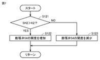
- FIG. It is a figure which shows the flow of the control process of the expansion valve 54 performed by the control device 10A of FIG.
- FIG. 1 is a functional block diagram showing the configuration of the refrigeration cycle device 100 according to the first embodiment.
- the refrigerant circulates.
- Examples of the refrigerating cycle device 100 include a refrigerator, an air conditioner, and a showcase.
- the refrigeration cycle apparatus 100 includes a compressor 1, a condenser 21 (first heat exchanger), a HIC (Heat Inter Changer) 22 (second heat exchanger), and a HIC 23 (first heat exchanger). 3 heat exchanger), evaporator 24 (4th heat exchanger), expansion valve 51 (1st expansion valve), expansion valve 52 (2nd expansion valve), expansion valve 53 (3rd expansion valve) And the temperature sensors Ts1 and Ts2.
- the compressor 1 includes a suction port Pts, a discharge port Ptd, a compression mechanism 60, an injection port Pj1 (first injection port), and an injection port Pj2 (second injection port).
- the compression mechanism 60 compresses the refrigerant from the suction port Pts and discharges it from the discharge port Ptd.
- Each of the injection ports Pj1 and Pj2 communicates with the compression mechanism 60.
- the refrigeration cycle device 100 has three circulation channels for the refrigerant.
- the refrigerant circulates in the order of the discharge port Ptd, the condenser 21, the HI C22, the HI C23, the expansion valve 51, the evaporator 24, and the suction port Pts.
- the refrigerant circulates in the order of the discharge port Ptd, the condenser 21, the HIC 22, the HIC 23, the expansion valve 52, the HIC 23, and the injection port Pj1.
- the refrigerant circulates in the order of the discharge port Ptd, the condenser 21, the HIC 22, the expansion valve 53, the heat exchanger HI C22, and the injection port Pj2.
- the refrigerant from the compressor 1 condenses in the condenser 21 and releases the heat of condensation to the air around the condenser 21.
- the refrigerant from the condenser 21 is cooled by the refrigerant from the expansion valve 53 in the HIC 22.
- the refrigerant from the HI 22 is cooled by the refrigerant from the expansion valve 52 in the HI 23.
- the refrigerant from the HIC 23 is decompressed by the expansion valve 53 and adiabatically expands, resulting in a gas-liquid two-phase state.
- the refrigerant from the expansion valve 51 absorbs heat of vaporization from the air around the evaporator 24 in the evaporator 24 and evaporates.
- the compressor 1 sucks the refrigerant from the evaporator 24 from the suction port Pts, adiabatically compresses it, and discharges it from the discharge port Ptd.
- the control device 10 acquires the temperature Td of the refrigerant discharged from the compressor 1 from the temperature sensor Ts1.
- the control device 10 controls the opening degree of the expansion valve 51 so that the temperature Td approaches the target temperature T1 (for example, 100 ° C.).
- the control device 10 acquires the temperature Th1 of the refrigerant flowing between the HIC 22 and the injection port Pj2 from the temperature sensor Ts2.
- the control device 10 controls the opening degree of the expansion valve 53 so that the superheat degree SH1 of the refrigerant flowing between the HIC 22 and the injection port Pj2 becomes the target value K1 (for example, 5K).
- the control device 10 controls the drive frequency of the compressor 1 to control the amount of refrigerant discharged by the compressor 1 per unit time.
- the control device 10 controls the opening degree of the expansion valve 51.
- the control device 10 controls the compressor 1 and the expansion valve 51 so that the degree of supercooling of the refrigerant flowing out of the HIC 23 becomes a target value (for example, 5K).
- the target temperature T1 and the target value K1 can be appropriately determined by an actual machine experiment or a simulation.
- FIG. 2 is a functional block diagram showing the configuration of the control device 10 of FIG.
- the control device 10 includes a processing circuit 11, a memory 12, and an input / output unit 13.
- the processing circuit 11 may be dedicated hardware or a CPU (Central Processing Unit) that executes a program stored in the memory 12.
- the processing circuit 11 includes, for example, a single circuit, a composite circuit, a programmed processor, a parallel programmed processor, an ASIC (Application Specific Integrated Circuit), an FPGA ( Field Programmable Gate Array) or a combination of these is applicable.
- the processing circuit 11 is a CPU, the function of the control device 10 is realized by software, firmware, or a combination of software and firmware.
- the software or firmware is described as a program and stored in the memory 12.
- the processing circuit 11 reads and executes the program stored in the memory 12.
- the memory 12 includes a non-volatile or volatile semiconductor memory (for example, RAM (Random Access Memory), ROM (Read Only Memory), flash memory, EPROM (Erasable Programmable Read Only Memory), or EEPROM (Electrically Erasable Programmable Read Only Memory). )), And includes magnetic discs, flexible discs, optical discs, compact discs, mini discs, or DVDs (Digital Versatile Discs).
- the CPU is also called a central processing unit, a processing unit, an arithmetic unit, a microprocessor, a microcomputer, a processor, or a DSP (Digital Signal Processor).
- FIG. 3 is a diagram showing a compression process of the compression mechanism 60 of FIG. Although FIG. 3 shows a case where the compression mechanism 60 is a scroll type, the compression mechanism 60 is not limited to the scroll type.
- the compression mechanism 60 may be of a rotary type.
- the compression mechanism 60 includes a fixed scroll 61 and a swing scroll 62. Due to the swing of the swing scroll 62, a spiral compression process in which the refrigerant is adiabatically compressed from the outer peripheral portion of the compression mechanism 60 toward the center is formed in the space between the fixed scroll 61 and the swing scroll 62. ..
- the suction port Pts communicates with the starting portion Cs of the compression process of the compression mechanism 60.
- the discharge port Ptd communicates with the end portion Cd of the compression process of the compression mechanism 60.
- the injection port Pj1 communicates with a portion Cj1 between the start portion and the end portion of the compression process of the compression mechanism 60.
- the refrigerant pressure P1 at the injection port Pj1 is higher than the refrigerant suction pressure Ps at the suction port Pts, and the geometric mean (Pd ⁇ Ps) of the refrigerant discharge pressure Pd and the suction pressure Ps at the discharge port Ptd is 0.5 or less. is there.
- the injection port Pj2 communicates with a portion Cj2 between the portion Cj1 and the end portion Cd of the compression process.
- the refrigerant pressure P2 at the injection port Pj2 is higher than the pressure P1 and lower than the discharge pressure Pd.
- the reliability of the compressor 1 decreases.
- the refrigerant contains carbon dioxide, the specific heat ratio of the refrigerant is often relatively large, so that the temperature Td tends to rise. Further, even when the evaporation temperature of the refrigeration cycle device 100 is ⁇ 10 ° C. or lower, such as when the refrigeration cycle device 100 is a refrigerator, the compression ratio is large and the temperature Td tends to rise.
- the refrigerant is cooled stepwise in the compression process by intermediate pressure injection.
- FIG. 4 is a flowchart showing a flow of control processing of the expansion valve 52 performed by the control device 10 of FIG.
- the process shown in FIG. 4 is called at each sampling time by a main routine (not shown) that performs integrated control of the refrigeration cycle apparatus 100.
- a main routine not shown
- FIGS. 5 and 7. the step is simply referred to as S.
- the control device 10 determines in S101 whether or not the temperature Td is larger than the target temperature T1.
- the control device 10 increases the opening degree of the expansion valve 52 in S102 and returns the process to the main routine.
- the control device 10 reduces the opening degree of the expansion valve 52 in S103 and returns the process to the main routine.
- FIG. 5 is a flowchart showing a flow of control processing of the expansion valve 53 performed by the control device 10 of FIG.
- the control device 10 determines whether or not the superheat degree SH1 is larger than the target value K1 in S111.
- the control device 10 increases the opening degree of the expansion valve 53 in S112 and returns the process to the main routine.
- the control device 10 reduces the opening degree of the expansion valve 53 in S113 and returns the process to the main routine.
- the refrigeration cycle apparatus According to the refrigeration cycle apparatus according to the first embodiment, it is possible to suppress the deterioration of the performance of the refrigeration cycle apparatus while maintaining the reliability of the compressor.
- Embodiment 2 In the first embodiment, a refrigeration cycle apparatus in which two-step intermediate injection is performed has been described. The intermediate injection may be performed in three or more steps. In the second embodiment, a refrigeration cycle apparatus in which three-step intermediate injection is performed will be described.
- FIG. 6 is a functional block diagram showing the configuration of the refrigeration cycle device 200 according to the second embodiment.
- the compressor 1 and the control device 10 are replaced with the compressor 1A and the control device 10A, respectively.
- the configuration of the compressor 1A is a configuration in which an injection port Pj3 (third injection port) is added to the compressor 1 of FIG.
- the control device 10A controls the expansion valve 54 in addition to the processing performed by the control device 10 of FIG. Other than these, the description is the same, so the description will not be repeated.
- the HI C25 is connected between the condenser 21 and the HI C22.
- the refrigerant circulates in the order of the discharge port Ptd, the condenser 21, the HI C25, the expansion valve 54, the HI C25, and the injection port Pj3.
- the refrigerant pressure P3 at the injection port Pj3 is higher than the pressure P2 and lower than the discharge pressure Pd.
- the control device 10A controls the opening degree of the expansion valve 54 so that the superheat degree SH2 of the refrigerant flowing between the HI C25 and the injection port Pj3 becomes the target value K2 (for example, 5K).
- the target value K2 can be appropriately determined by an actual machine experiment or a simulation.
- FIG. 7 is a diagram showing a flow of control processing of the expansion valve 54 performed by the control device 10A of FIG.
- the control device 10A determines whether or not the superheat degree SH2 is larger than the target value K2 (for example, 5K) in S121.
- the control device 10A increases the opening degree of the expansion valve 54 in S122 and returns the process to the main routine.
- the control device 10A reduces the opening degree of the expansion valve 54 in S123 and returns the process to the main routine.
Landscapes
- Engineering & Computer Science (AREA)
- Physics & Mathematics (AREA)
- Mechanical Engineering (AREA)
- Thermal Sciences (AREA)
- General Engineering & Computer Science (AREA)
- Air Conditioning Control Device (AREA)
- Applications Or Details Of Rotary Compressors (AREA)
Priority Applications (2)
| Application Number | Priority Date | Filing Date | Title |
|---|---|---|---|
| JP2021554031A JP7224486B2 (ja) | 2019-11-01 | 2019-11-01 | 冷凍サイクル装置 |
| PCT/JP2019/043100 WO2021084744A1 (ja) | 2019-11-01 | 2019-11-01 | 冷凍サイクル装置 |
Applications Claiming Priority (1)
| Application Number | Priority Date | Filing Date | Title |
|---|---|---|---|
| PCT/JP2019/043100 WO2021084744A1 (ja) | 2019-11-01 | 2019-11-01 | 冷凍サイクル装置 |
Publications (1)
| Publication Number | Publication Date |
|---|---|
| WO2021084744A1 true WO2021084744A1 (ja) | 2021-05-06 |
Family
ID=75715896
Family Applications (1)
| Application Number | Title | Priority Date | Filing Date |
|---|---|---|---|
| PCT/JP2019/043100 Ceased WO2021084744A1 (ja) | 2019-11-01 | 2019-11-01 | 冷凍サイクル装置 |
Country Status (2)
| Country | Link |
|---|---|
| JP (1) | JP7224486B2 (https=) |
| WO (1) | WO2021084744A1 (https=) |
Cited By (1)
| Publication number | Priority date | Publication date | Assignee | Title |
|---|---|---|---|---|
| WO2025196897A1 (ja) * | 2024-03-18 | 2025-09-25 | 三菱電機株式会社 | 冷凍サイクル装置 |
Citations (6)
| Publication number | Priority date | Publication date | Assignee | Title |
|---|---|---|---|---|
| JP2008232613A (ja) * | 2007-03-21 | 2008-10-02 | Grasso Gmbh Refrigeration Technology | 2段式の圧縮を行うco2冷凍装置の制御法 |
| JP2009229055A (ja) * | 2008-02-28 | 2009-10-08 | Daikin Ind Ltd | 冷凍装置 |
| KR20160086654A (ko) * | 2015-01-12 | 2016-07-20 | 엘지전자 주식회사 | 공기 조화기 |
| JP2018500533A (ja) * | 2014-12-11 | 2018-01-11 | アンジェラントーニ テスト テクノロジーズ ソチエタ レスポンサビリタ リミタータ イン ショート エイティーティー ソチエタ レスポンサビリタ リミタータ | 冷蔵装置 |
| JP2018087688A (ja) * | 2018-02-16 | 2018-06-07 | ダイキン工業株式会社 | 空気調和装置 |
| JP2018516355A (ja) * | 2015-10-27 | 2018-06-21 | 広東美的暖通設備有限公司Gd Midea Heating & Ventilating Equipment Co.,Ltd. | 蒸気噴射増エンタルピー空気調和システム |
-
2019
- 2019-11-01 WO PCT/JP2019/043100 patent/WO2021084744A1/ja not_active Ceased
- 2019-11-01 JP JP2021554031A patent/JP7224486B2/ja active Active
Patent Citations (6)
| Publication number | Priority date | Publication date | Assignee | Title |
|---|---|---|---|---|
| JP2008232613A (ja) * | 2007-03-21 | 2008-10-02 | Grasso Gmbh Refrigeration Technology | 2段式の圧縮を行うco2冷凍装置の制御法 |
| JP2009229055A (ja) * | 2008-02-28 | 2009-10-08 | Daikin Ind Ltd | 冷凍装置 |
| JP2018500533A (ja) * | 2014-12-11 | 2018-01-11 | アンジェラントーニ テスト テクノロジーズ ソチエタ レスポンサビリタ リミタータ イン ショート エイティーティー ソチエタ レスポンサビリタ リミタータ | 冷蔵装置 |
| KR20160086654A (ko) * | 2015-01-12 | 2016-07-20 | 엘지전자 주식회사 | 공기 조화기 |
| JP2018516355A (ja) * | 2015-10-27 | 2018-06-21 | 広東美的暖通設備有限公司Gd Midea Heating & Ventilating Equipment Co.,Ltd. | 蒸気噴射増エンタルピー空気調和システム |
| JP2018087688A (ja) * | 2018-02-16 | 2018-06-07 | ダイキン工業株式会社 | 空気調和装置 |
Cited By (1)
| Publication number | Priority date | Publication date | Assignee | Title |
|---|---|---|---|---|
| WO2025196897A1 (ja) * | 2024-03-18 | 2025-09-25 | 三菱電機株式会社 | 冷凍サイクル装置 |
Also Published As
| Publication number | Publication date |
|---|---|
| JPWO2021084744A1 (https=) | 2021-05-06 |
| JP7224486B2 (ja) | 2023-02-17 |
Similar Documents
| Publication | Publication Date | Title |
|---|---|---|
| US12181168B2 (en) | Air conditioner and control method thereof | |
| JP7224503B2 (ja) | 冷凍サイクル装置 | |
| JP2010096490A (ja) | 冷凍装置 | |
| WO2021084743A1 (ja) | 冷凍サイクル装置 | |
| US10907872B2 (en) | Refrigerator | |
| CN114402172A (zh) | 空调机 | |
| JP2012180963A (ja) | 冷凍サイクル | |
| JPH10325621A (ja) | 空気調和装置 | |
| JP5735441B2 (ja) | 冷凍装置 | |
| JP7224486B2 (ja) | 冷凍サイクル装置 | |
| CN108369045A (zh) | 空调机 | |
| US20220390161A1 (en) | Refrigeration cycle apparatus | |
| CN108027176A (zh) | 多级压缩式制冷循环装置 | |
| WO2021111605A1 (ja) | 冷凍サイクル装置 | |
| CN104508408B (zh) | 冰箱 | |
| JP6825736B2 (ja) | 冷凍サイクル装置 | |
| JP7670996B2 (ja) | 冷凍装置 | |
| JP2020186909A5 (https=) | ||
| JP2006138632A (ja) | 冷凍機 | |
| JP2006194526A (ja) | 空気調和装置 | |
| JP2008096072A (ja) | 冷凍サイクル装置 | |
| JP7683823B2 (ja) | 冷凍サイクル装置 | |
| JP7843915B2 (ja) | 除湿装置 | |
| JP7130067B2 (ja) | 冷凍装置 | |
| JP2015148414A (ja) | 空気調和機 |
Legal Events
| Date | Code | Title | Description |
|---|---|---|---|
| 121 | Ep: the epo has been informed by wipo that ep was designated in this application |
Ref document number: 19950732 Country of ref document: EP Kind code of ref document: A1 |
|
| ENP | Entry into the national phase |
Ref document number: 2021554031 Country of ref document: JP Kind code of ref document: A |
|
| NENP | Non-entry into the national phase |
Ref country code: DE |
|
| 122 | Ep: pct application non-entry in european phase |
Ref document number: 19950732 Country of ref document: EP Kind code of ref document: A1 |