WO2021079880A1 - 制御装置、電動圧縮機、リップル電圧の検出方法及びプログラム - Google Patents
制御装置、電動圧縮機、リップル電圧の検出方法及びプログラム Download PDFInfo
- Publication number
- WO2021079880A1 WO2021079880A1 PCT/JP2020/039408 JP2020039408W WO2021079880A1 WO 2021079880 A1 WO2021079880 A1 WO 2021079880A1 JP 2020039408 W JP2020039408 W JP 2020039408W WO 2021079880 A1 WO2021079880 A1 WO 2021079880A1
- Authority
- WO
- WIPO (PCT)
- Prior art keywords
- voltage
- waveform
- ripple voltage
- value
- unit
- Prior art date
- Legal status (The legal status is an assumption and is not a legal conclusion. Google has not performed a legal analysis and makes no representation as to the accuracy of the status listed.)
- Ceased
Links
Images



Classifications
-
- F—MECHANICAL ENGINEERING; LIGHTING; HEATING; WEAPONS; BLASTING
- F04—POSITIVE - DISPLACEMENT MACHINES FOR LIQUIDS; PUMPS FOR LIQUIDS OR ELASTIC FLUIDS
- F04B—POSITIVE-DISPLACEMENT MACHINES FOR LIQUIDS; PUMPS
- F04B49/00—Control, e.g. of pump delivery, or pump pressure of, or safety measures for, machines, pumps, or pumping installations, not otherwise provided for, or of interest apart from, groups F04B1/00 - F04B47/00
- F04B49/10—Other safety measures
-
- F—MECHANICAL ENGINEERING; LIGHTING; HEATING; WEAPONS; BLASTING
- F04—POSITIVE - DISPLACEMENT MACHINES FOR LIQUIDS; PUMPS FOR LIQUIDS OR ELASTIC FLUIDS
- F04B—POSITIVE-DISPLACEMENT MACHINES FOR LIQUIDS; PUMPS
- F04B17/00—Pumps characterised by combination with, or adaptation to, specific driving engines or motors
- F04B17/03—Pumps characterised by combination with, or adaptation to, specific driving engines or motors driven by electric motors
-
- F—MECHANICAL ENGINEERING; LIGHTING; HEATING; WEAPONS; BLASTING
- F04—POSITIVE - DISPLACEMENT MACHINES FOR LIQUIDS; PUMPS FOR LIQUIDS OR ELASTIC FLUIDS
- F04B—POSITIVE-DISPLACEMENT MACHINES FOR LIQUIDS; PUMPS
- F04B35/00—Piston pumps specially adapted for elastic fluids and characterised by the driving means to their working members, or by combination with, or adaptation to, specific driving engines or motors, not otherwise provided for
- F04B35/04—Piston pumps specially adapted for elastic fluids and characterised by the driving means to their working members, or by combination with, or adaptation to, specific driving engines or motors, not otherwise provided for the means being electric
-
- F—MECHANICAL ENGINEERING; LIGHTING; HEATING; WEAPONS; BLASTING
- F04—POSITIVE - DISPLACEMENT MACHINES FOR LIQUIDS; PUMPS FOR LIQUIDS OR ELASTIC FLUIDS
- F04B—POSITIVE-DISPLACEMENT MACHINES FOR LIQUIDS; PUMPS
- F04B49/00—Control, e.g. of pump delivery, or pump pressure of, or safety measures for, machines, pumps, or pumping installations, not otherwise provided for, or of interest apart from, groups F04B1/00 - F04B47/00
- F04B49/06—Control using electricity
- F04B49/065—Control using electricity and making use of computers
-
- H—ELECTRICITY
- H02—GENERATION; CONVERSION OR DISTRIBUTION OF ELECTRIC POWER
- H02P—CONTROL OR REGULATION OF ELECTRIC MOTORS, ELECTRIC GENERATORS OR DYNAMO-ELECTRIC CONVERTERS; CONTROLLING TRANSFORMERS, REACTORS OR CHOKE COILS
- H02P29/00—Arrangements for regulating or controlling electric motors, appropriate for both AC and DC motors
-
- H—ELECTRICITY
- H02—GENERATION; CONVERSION OR DISTRIBUTION OF ELECTRIC POWER
- H02P—CONTROL OR REGULATION OF ELECTRIC MOTORS, ELECTRIC GENERATORS OR DYNAMO-ELECTRIC CONVERTERS; CONTROLLING TRANSFORMERS, REACTORS OR CHOKE COILS
- H02P29/00—Arrangements for regulating or controlling electric motors, appropriate for both AC and DC motors
- H02P29/02—Providing protection against overload without automatic interruption of supply
- H02P29/024—Detecting a fault condition, e.g. short circuit, locked rotor, open circuit or loss of load
- H02P29/0241—Detecting a fault condition, e.g. short circuit, locked rotor, open circuit or loss of load the fault being an overvoltage
-
- F—MECHANICAL ENGINEERING; LIGHTING; HEATING; WEAPONS; BLASTING
- F04—POSITIVE - DISPLACEMENT MACHINES FOR LIQUIDS; PUMPS FOR LIQUIDS OR ELASTIC FLUIDS
- F04B—POSITIVE-DISPLACEMENT MACHINES FOR LIQUIDS; PUMPS
- F04B2203/00—Motor parameters
- F04B2203/02—Motor parameters of rotating electric motors
- F04B2203/0202—Voltage
-
- F—MECHANICAL ENGINEERING; LIGHTING; HEATING; WEAPONS; BLASTING
- F04—POSITIVE - DISPLACEMENT MACHINES FOR LIQUIDS; PUMPS FOR LIQUIDS OR ELASTIC FLUIDS
- F04B—POSITIVE-DISPLACEMENT MACHINES FOR LIQUIDS; PUMPS
- F04B2203/00—Motor parameters
- F04B2203/02—Motor parameters of rotating electric motors
- F04B2203/0209—Rotational speed
Definitions
- This disclosure relates to a control device, an electric compressor, a ripple voltage detection method and a program.
- the present application claims priority based on Japanese Patent Application No. 2019-193693 filed in Japan on October 24, 2019, the contents of which are incorporated herein by reference.
- Ripple voltage may occur in the drive circuit that drives the electric compressor. When the ripple voltage becomes large, resonance occurs and an excessive current flows.
- the present disclosure provides a control device, an electric compressor, a ripple voltage detection method and a program capable of solving the above problems.
- the control device of the present disclosure includes an acquisition unit that samples the voltage value of the input voltage of a battery-powered electric compressor at unequal intervals, and a ripple of the input voltage based on the voltage value sampled at unequal intervals. It includes a waveform calculation unit that calculates the waveform of a component.
- the program of the present disclosure is a means for unequally sampling the input voltage of a battery-powered electric compressor, a ripple of the input voltage based on the unequally sampled voltage values. It functions as a means for calculating the waveform of a component.
- control device electric compressor, ripple voltage detection method and program, it is possible to reliably detect an abnormality in the ripple voltage.
- the vehicle air conditioner 30 includes an electric compressor 20.
- the electric compressor 20 is an inverter-integrated electric compressor in which the inverter 7 is integrally incorporated.
- the electric compressor 20 includes a power supply circuit 8 including a capacitor 6 and an inverter 7, a motor 9, a control device 10, a voltmeter 11, and a compression unit 12.
- the electric compressor 20 is driven by the inverter 7 converting the high-voltage DC power supplied from the battery 1 into three-phase AC power and applying it to the motor 9.
- the inverter 7 and the motor 9 are connected by a power line.
- the inverter 7 converts the DC power supplied from the battery 1 into three-phase AC and supplies it to the motor 9.
- the inverter 7 is controlled by the control device 10.
- the control device 10 includes a microcomputer, and controls the motor 9 to a desired operation via the inverter 7 based on a control signal acquired from an ECU (Electric Control Unit) or the like (not shown). For example, the control device 10 controls the rotation speed of the motor 9.
- the compression unit 12 compresses the refrigerant and supplies the refrigerant to the refrigerant circuit (not shown) included in the vehicle air conditioner 30.
- the inverter 7, the voltmeter 11, and the control device 10 are connected by a signal line.
- the voltmeter 11 measures the DC voltage input to the inverter 7 and outputs the measured voltage value to the control device 10. The voltage measured by the voltmeter 11 is called the input voltage.
- the control device 10 includes an acquisition unit 101, a waveform calculation unit 102, a determination unit 103, and a control unit 104.
- the acquisition unit 101 samples the voltage values measured by the voltmeter 11 at unequal intervals.
- the waveform calculation unit 102 calculates a waveform from voltage values sampled by the acquisition unit 101 at unequal intervals.
- the waveform calculated by the waveform calculation unit 102 is a ripple component of the input voltage, that is, a ripple voltage.
- the ripple voltage may include one originating from the electric compressor 20 (inverter 7) and one originating from the vehicle equipment 40 (inverter 3).
- the determination unit 103 calculates the difference between the maximum value and the minimum value of the voltage value in a predetermined minute time based on the waveform calculated by the waveform calculation unit 102. This value is called the ripple voltage value W.
- the determination unit 103 compares the value W of the ripple voltage with the predetermined threshold value ⁇ . When the value W of the ripple voltage is equal to or greater than the threshold value ⁇ , the determination unit 103 determines to perform resonance protection control for protecting the circuit from resonance.
- the resonance protection control is a control that reduces the rotation speed of the motor 9 to suppress the value W of the ripple voltage to less than the threshold value.
- the control unit 104 instructs the inverter 7 to rotate the motor 9.
- the control unit 104 stops the motor 9.
- the control unit 104 reduces the rotation speed of the motor 9 to a predetermined rotation speed X (rpm).
- X rotation speed
- the waveform calculation unit 102 uses the sine wave as the waveform of the ripple voltage at time Tp.
- the waveform C1 is a waveform of the ripple voltage calculated by the waveform calculation unit 102 based on the points P1 to P11.
- the waveform C2 is a waveform of the ripple voltage at the time Tq calculated by the waveform calculation unit 102 based on the points Q1 to Q11.
- Wp is the ripple voltage value Wp indicated by the waveform C1
- Wq is the ripple voltage value Wq indicated by the waveform C2.
- the acquisition unit 101 samples the input voltage at unequal intervals, and the waveform calculation unit 102 calculates the waveform based on those values. In this way, no matter what frequency the ripple voltage is generated, it is unlikely that the vibration will be overlooked.
- the timing for sampling the voltage values in the time width T1 at unequal intervals may be predetermined, or may be randomly set by the acquisition unit 101 each time the time width T1 elapses.
- the length of the unit time T1 and the number of samples sampled during that period are determined so that a number of samples required for waveform calculation can be obtained and an abnormal ripple voltage detection delay does not occur. For example, by randomly changing the sampling interval for each unit time, it is considered that the risk of omission of detection of the ripple voltage due to the overlap of the ripple voltage cycle and the sampling cycle can be further reduced.
- control device 10 samples the input voltage at unequal intervals for each unit time Tp, calculates the waveform of the ripple voltage during this period, and monitors the behavior of the ripple voltage.
- the control device 10 performs resonance protection control while continuing to monitor the ripple voltage.
- FIG. 3 is a diagram illustrating an example of resonance protection control in one embodiment.
- FIG. 3 The vertical axis of the upper figure shows the value W of the ripple voltage originating from the electric compressor 20, and the horizontal axis shows the time.
- FIG. 3 The vertical axis in the lower figure shows the rotation speed of the motor 9, and the horizontal axis shows the time. The same position on the horizontal axis in the upper figure and the lower figure in FIG. 3 indicates the same time.
- the value W of the ripple voltage at time t0 is 0.
- the rotation speed of the motor 9 at time t0 is Y (rpm).
- Y (rpm) is a required rotation speed determined by the ECU of the vehicle based on the set temperature of heating and cooling set by the user.
- the value W of the ripple voltage is equal to or higher than the threshold value ⁇ .
- the determination unit 103 instructs the control unit 104 to execute the resonance protection control based on the value W becoming the threshold value ⁇ or more. Then, the control unit 104 instructs the inverter 7 to have a rotation speed of 0 (zero).
- Graph L1 shows the transition of the rotation speed of the motor 9 when the motor 9 is stopped
- graph A1 shows the transition of the ripple voltage value W.
- the value W of the ripple voltage also decreases as shown in the graph A1. This makes it possible to prevent the occurrence of resonance.
- the control unit 104 may reduce the rotation speed of the motor 9 instead of stopping the motor 9.
- Graph L2 shows the transition of the rotation speed when the rotation speed of the motor 9 is lowered
- graph A2 shows the transition of the ripple voltage value W.
- the control unit 104 sets X (rpm), which is a value smaller than Y, as the target rotation speed, and instructs the inverter 7 to rotate the rotation speed X.
- the control unit 104 sequentially sets the rotation speed set stepwise from the required rotation speed Y (rpm) to the rotation speed X (rpm) to the target rotation speed, and transfers the rotation speed to the inverter 7 at predetermined time intervals. You may instruct and gradually reduce the rotation speed of the motor 9 to the rotation speed X.
- the rotation speed of the motor 9 gradually decreases, and decreases to X (rpm) at time t1-1. This makes it possible to prevent the occurrence of resonance.
- the resonance protection control by operating the motor 9 at the rotation speed X without stopping, the air conditioning by the vehicle air conditioner 30 can be continued even if it is weak, and the deterioration of the user's comfort can be suppressed.
- Ripple voltage abnormality may occur due to a transient phenomenon. Therefore, the control unit 104 causes an abnormality in the ripple voltage when a predetermined time elapses after the value W of the ripple voltage drops below the threshold value ⁇ , regardless of whether the motor 9 is stopped or the rotation speed of the motor 9 is lowered. It may be determined that the transient factor may have been removed, and control may be performed to increase the rotation speed of the motor 9 again toward the required rotation speed Y required by the vehicle air conditioner 30. As a result, the operating state of the vehicle air conditioner 30 can be brought closer to the operating state according to the load, so that the comfort of the user can be restored.
- the control unit 104 may not increase the rotation speed of the motor 9 to Y (rpm) at a time, but may increase the rotation speed stepwise toward the required rotation speed Y. In this case, even if the rotation speed of the motor 9 cannot be increased to Y, the control unit 104 may increase the rotation speed to the maximum rotation speed at which an abnormality of the ripple voltage does not occur and continue the operation as it is. Good.
- the control unit 104 can reduce the value W of the ripple voltage by lowering the rotation speed of the motor 9.
- the abnormality of the ripple voltage cannot be removed by the control of the control device 10. For example, if the value W is equal to or higher than the threshold value ⁇ even if the rotation speed of the motor 9 is reduced, the ripple voltage may be generated by the vehicle equipment 40.
- the control device 10 may wait until the value W of the ripple voltage becomes less than the threshold value ⁇ while the motor 9 is stopped.
- the control device 10 may record a log describing that an abnormality of the ripple voltage originating from the vehicle device 40 has occurred in a storage unit (not shown). For example, by providing the log to the manufacturer of the vehicle equipment 40, it is possible to request that the generation of an abnormal ripple voltage be suppressed.
- FIG. 4 is a flowchart showing an example of control in one embodiment.
- the motor 9 is driven at a required rotation speed Y according to the air conditioning load of the vehicle air conditioner 30.
- the acquisition unit 101 samples the latest voltage values measured by the voltmeter 11 at unequal intervals (step S10).
- the acquisition unit 101 outputs the sampled voltage value to the waveform calculation unit 102.
- the waveform calculation unit 102 calculates the waveform of the ripple voltage in a predetermined unit time (time width T1) (step S11).
- the waveform calculation unit 102 calculates a ripple voltage waveform by performing sine wave fitting on a plurality of voltage values acquired by the acquisition unit 101 at unequal intervals within a unit time.
- the waveform calculation unit 102 calculates the ripple voltage value W (for example, Wp and Wq in FIG. 2) for the calculated waveform.
- the waveform calculation unit 102 outputs the ripple voltage value W to the determination unit 103.
- the determination unit 103 compares the value W of the ripple voltage with the threshold value ⁇ (step S12). When the value W is less than the threshold value ⁇ (step S12; No), the determination unit 103 determines that the possibility of resonance due to the ripple voltage is low, and repeats the process from step S10.
- step S12 When the value W of the ripple voltage is equal to or higher than the threshold value ⁇ (step S12; Yes), the determination unit 103 determines that resonance due to the ripple voltage may occur, and instructs the control unit 104 to start the resonance protection control.
- the control unit 104 stops the motor 9 or reduces the rotation speed of the motor 9 to a predetermined rotation speed X (rpm) (step S13). Even after the motor 9 is stopped or the like, the process from step S10 is repeated.
- the resonance protection control for example, the rotation speed of the motor 9 may be increased again after a predetermined time has elapsed after the value W of the ripple voltage drops below the threshold value ⁇ .
- the value W of the ripple voltage remains equal to or higher than the threshold value ⁇ even after the resonance protection control is performed, it is considered that the ripple voltage originating from the vehicle device 40 is abnormal.
- the occurrence of an abnormality in the ripple voltage may be recorded in a log, or an alarm may be notified to the vehicle equipment 40 side.
- the value of the input voltage of the electric compressor 20 is sampled at unequal intervals, and the ripple voltage waveform is calculated based on the sampling result.
- the vibration can be detected without being missed, and the vibration state of the ripple voltage can be grasped.
- FIG. 5 is a diagram showing an example of the hardware configuration of the control device in one embodiment.
- the computer 900 includes a CPU 901, a main storage device 902, an auxiliary storage device 903, an input / output interface 904, and a communication interface 905.
- the control device 10 described above is mounted on the computer 900.
- Each of the above-mentioned functions is stored in the auxiliary storage device 903 in the form of a program.
- the CPU 901 reads the program from the auxiliary storage device 903, expands it to the main storage device 902, and executes the above processing according to the program.
- the CPU 901 reserves a storage area in the main storage device 902 according to the program.
- the CPU 901 secures a storage area for storing the data being processed in the auxiliary storage device 903 according to the program.
- Each function unit is recorded by recording a program for realizing all or a part of the functions of the control device 10 on a computer-readable recording medium, causing the computer system to read the program recorded on the recording medium, and executing the program. May be performed by.
- the term "computer system” as used herein includes hardware such as an OS and peripheral devices.
- the "computer system” shall also include a homepage providing environment (or display environment) if a WWW system is used.
- the "computer-readable recording medium” refers to a portable medium such as a CD, DVD, or USB, or a storage device such as a hard disk built in a computer system.
- the distributed computer 900 may expand the program to the main storage device 902 and execute the above processing.
- the above-mentioned program may be for realizing a part of the above-mentioned functions, and may further realize the above-mentioned functions in combination with a program already recorded in the computer system.
- control device 10 The control device 10, the electric compressor 20, the ripple voltage detection method and the program described in each embodiment are grasped as follows, for example.
- the control device 10 is the control device 10 of (1), and the acquisition unit 101 sets the unit times at unequal intervals for each predetermined unit time (Tp, Tq). A plurality of time points to be divided into are determined, the sampling is performed at each time point (points P1 to P11, points Q1 to Q11), and the waveform calculation unit 102 calculates the waveform every unit time.
- the sampling interval By changing the sampling interval in various ways, it is possible to reduce the risk of omission of detection of the ripple voltage due to the overlap of the ripple voltage cycle and the sampling cycle.
- the control device 10 is the control device 10 of (1) to (3), and determines whether or not the ripple voltage value W indicated by the waveform is equal to or higher than a predetermined threshold value ⁇ .
- a unit 103 and a control unit 104 that lowers the rotation speed of the motor 9 of the electric compressor 20 when the value W of the ripple voltage is equal to or higher than the threshold value ⁇ are further provided.
- the occurrence of resonance can be avoided by lowering (including stopping) the rotation speed of the motor 9.
- the electric compressor 20 according to the fifth aspect includes the control devices 10 of (1) to (4).
- the voltage values of the input voltage of the electric compressor 20 driven by the battery 1 are sampled at unequal intervals, and the voltage values sampled at unequal intervals are used. Based on this, the waveform of the ripple component of the input voltage is calculated.
- the program according to the seventh aspect is based on a means for sampling the voltage value of the input voltage of the electric compressor driven by the battery of the computer at unequal intervals, and the voltage value sampled at unequal intervals. , As a means for calculating the waveform of the ripple component of the input voltage.
- control device electric compressor, ripple voltage detection method and program, it is possible to reliably detect an abnormality in the ripple voltage.
Landscapes
- Engineering & Computer Science (AREA)
- Mechanical Engineering (AREA)
- General Engineering & Computer Science (AREA)
- Power Engineering (AREA)
- Computer Hardware Design (AREA)
- Control Of Positive-Displacement Pumps (AREA)
- Control Of Ac Motors In General (AREA)
- Control Of Electric Motors In General (AREA)
- Air-Conditioning For Vehicles (AREA)
- Inverter Devices (AREA)
Abstract
リップル電圧を検出する方法を提供する。制御装置は、バッテリで駆動する電動圧縮機の入力電圧の電圧値を不等間隔で取得する取得部と、取得した電圧値に基づいて、入力電圧のリップル成分の波形を演算する波形演算部と、を備える。
Description
本開示は、制御装置、電動圧縮機、リップル電圧の検出方法及びプログラムに関する。本願は、2019年10月24日に、日本に出願された特願2019-193693号に基づき優先権を主張し、その内容をここに援用する。
車両に搭載されたカーエアコンの構成要素の1つに電動圧縮機がある。電動圧縮機を駆動する駆動回路では、リップル電圧が発生することがある。リップル電圧が大きくなると共振が生じ、過大な電流が流れる。
特許文献1には、車両用交流発電機のリップル電圧を検出し、リップル電圧の最大値と最小値の差が所定値を超えると、交流発電機が故障していると判断する技術が開示されている。
リップル電圧の共振による過大な電流から電動圧縮機を保護するためには、リップル電圧の振動状態を検出できる必要がある。
本開示は、上記課題を解決することができる制御装置、電動圧縮機、リップル電圧の検出方法及びプログラムを提供する。
本開示の制御装置は、バッテリで駆動する電動圧縮機の入力電圧の電圧値を不等間隔にサンプリングする取得部と、不等間隔にサンプリングされた前記電圧値に基づいて、前記入力電圧のリップル成分の波形を演算する波形演算部と、を備える。
本開示の電動圧縮機は、上記の制御装置を備える。
本開示のリップル電圧の検出方法では、バッテリで駆動する電動圧縮機の入力電圧の電圧値を不等間隔にサンプリングし、不等間隔にサンプリングされた前記電圧値に基づいて、前記入力電圧のリップル成分の波形を演算する。
本開示のプログラムは、コンピュータを、バッテリで駆動する電動圧縮機の入力電圧の電圧値を不等間隔にサンプリングする手段、不等間隔にサンプリングされた前記電圧値に基づいて、前記入力電圧のリップル成分の波形を演算する手段、として機能させる。
上述の制御装置、電動圧縮機、リップル電圧の検出方法及びプログラムによれば、リップル電圧の異常を確実に検出することができる。
<実施形態>
以下、一実施形態に係る電動圧縮機について、図1~図5を参照しながら説明する。
(構成)
図1に、車両空調機30が備える電動圧縮機20の概略構成の一例を示す。図示するバッテリ1と、車両空調機30と、車両機器40と、これらを駆動する電気回路は、車両に搭載される。インダクタ5a、5bは、バッテリ1と車両空調機30および車両機器40を含む電気回路のインダクタ成分を示す。
バッテリ1は、車両(車両空調機30の外部)に搭載された電源ユニットである。バッテリ1は、車両空調機30と車両機器40に高圧の直流電力を供給する。車両機器40は、コンデンサ2およびインバータ3、インバータ3に接続された負荷4を備える。車両機器40では、バッテリ1から供給される高電圧の直流電力をインバータ3が三相交流電力に変換し、それを負荷4に供給する。インバータ3のキャリア周波数をf1とすると、電気回路には、車両機器40を発生源とする周波数f1のリップル電圧(後述)が発生する場合がある。
以下、一実施形態に係る電動圧縮機について、図1~図5を参照しながら説明する。
(構成)
図1に、車両空調機30が備える電動圧縮機20の概略構成の一例を示す。図示するバッテリ1と、車両空調機30と、車両機器40と、これらを駆動する電気回路は、車両に搭載される。インダクタ5a、5bは、バッテリ1と車両空調機30および車両機器40を含む電気回路のインダクタ成分を示す。
バッテリ1は、車両(車両空調機30の外部)に搭載された電源ユニットである。バッテリ1は、車両空調機30と車両機器40に高圧の直流電力を供給する。車両機器40は、コンデンサ2およびインバータ3、インバータ3に接続された負荷4を備える。車両機器40では、バッテリ1から供給される高電圧の直流電力をインバータ3が三相交流電力に変換し、それを負荷4に供給する。インバータ3のキャリア周波数をf1とすると、電気回路には、車両機器40を発生源とする周波数f1のリップル電圧(後述)が発生する場合がある。
車両空調機30は、電動圧縮機20を備えている。電動圧縮機20は、インバータ7が一体に組み込まれたインバータ一体型電動圧縮機である。電動圧縮機20は、コンデンサ6およびインバータ7を含む電源回路8と、モータ9と、制御装置10と、電圧計11と、圧縮部12と、を備える。電動圧縮機20は、バッテリ1から供給される高電圧の直流電力をインバータ7が三相交流電力に変換し、それをモータ9に印加することによって駆動される。インバータ7とモータ9は電力線で接続される。インバータ7は、バッテリ1から供給された直流電力を三相交流に変換し、モータ9へ供給する。インバータ7は、制御装置10によって制御される。制御装置10は、マイコンを備え、図示しないECU(Electric Control Unit)等から取得した制御信号に基づいて、インバータ7を介してモータ9を所望の動作に制御する。例えば、制御装置10は、モータ9の回転数を制御する。モータ9がインバータ7からの指示によって回転駆動することにより、圧縮部12が冷媒を圧縮し、車両空調機30が備える冷媒回路(図示せず)へ冷媒を供給する。インバータ7および電圧計11と制御装置10とは信号線で接続されている。電圧計11は、インバータ7に入力される直流電圧を計測し、計測した電圧値を制御装置10へ出力する。電圧計11が計測する電圧を入力電圧と呼ぶ。電圧計11が計測する入力電圧には、リップル成分が含まれる場合がある。電圧計11が計測する電圧値から、バッテリ1由来の直流電圧値を差し引いた値をリップル電圧と呼ぶ。インバータ7のキャリア周波数をf0とすると、電気回路には、電動圧縮機20を発生源とする周波数f0のリップル電圧が発生する場合がある。周波数f0又はf1のリップル電圧が大きくなると、コンデンサ2、6およびインダクタ5a、5bで形成される共振回路で共振が生じ、図1の電気回路中に過大な電流が流れる。そこで、制御装置10は、電圧計11が計測した電圧値の変動を監視し、リップル電圧の値Wが所定の閾値α以上となると、リップル電圧の異常と判定し、モータ9を停止又は減速させ、リップル電圧の値Wを抑制する共振保護制御を行う。これにより、電動圧縮機20を発生源とするリップル電圧が抑制される。
制御装置10は、取得部101と、波形演算部102と、判定部103と、制御部104と、を備える。
取得部101は、電圧計11が計測した電圧値を不等間隔にサンプリングする。
波形演算部102は、取得部101が不等間隔にサンプリングした電圧値から波形を演算する。波形演算部102が演算した波形は、入力電圧のリップル成分、つまり、リップル電圧である。リップル電圧には、電動圧縮機20(インバータ7)を発生源とするもののほか、車両機器40(インバータ3)を発生源とするものが含まれ得る。
取得部101は、電圧計11が計測した電圧値を不等間隔にサンプリングする。
波形演算部102は、取得部101が不等間隔にサンプリングした電圧値から波形を演算する。波形演算部102が演算した波形は、入力電圧のリップル成分、つまり、リップル電圧である。リップル電圧には、電動圧縮機20(インバータ7)を発生源とするもののほか、車両機器40(インバータ3)を発生源とするものが含まれ得る。
判定部103は、波形演算部102が演算した波形に基づいて、所定の微小時間における電圧値の最大値と最小値の差を演算する。この値をリップル電圧の値Wと呼ぶ。判定部103は、リップル電圧の値Wと所定の閾値αとを比較する。リップル電圧の値Wが閾値α以上の場合、判定部103は、共振から回路を保護する共振保護制御を行うことを決定する。共振保護制御とは、モータ9の回転数を低下させて、リップル電圧の値Wを閾値未満に抑制する制御である。
制御部104は、インバータ7にモータ9の回転数を指示する。判定部103が、共振保護制御を行うことを決定すると、制御部104は、モータ9を停止させる。あるいは、制御部104は、モータ9の回転数を所定の回転数X(rpm)へ低下させる。モータ9を停止または回転数を低下させると、電動圧縮機20を発生源とするリップル電圧の値Wを小さくすることができる。
(リップル電圧の検出処理)
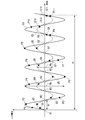
図2は、一実施形態におけるリップル電圧の検出処理を説明する図である。
図2の縦軸は入力電圧、横軸は時間である。図2にプロットした菱形の点は、取得部101が不等間隔にサンプリングした入力電圧の電圧値である。点P1~P11は、ある単位時間Tp(時間幅T1)に連続してサンプリングされた電圧値、点Q1~Q11は、別の単位時間Tq(時間幅T1)に連続してサンプリングされた電圧値である。波形演算部102は、時間幅T1の間に連続してサンプリングされた電圧値に基づいて、リップル電圧の波形を演算する。点P1~P11を例とすると、波形演算部102は、ある正弦波を仮定して(例えば、y=a+b×sin(c))、点P1~P11の各々に対応する時刻における仮定した正弦波の値が、点P1~P11の電圧値に近似するように、仮定した正弦波の式のパラメータa~cを調整することによりフィッティングを行う。近似する正弦波が演算できると、波形演算部102は、その正弦波を、時間Tpにおけるリップル電圧の波形とする。波形C1は、点P1~P11に基づいて、波形演算部102が演算したリップル電圧の波形である。同様に、波形C2は、点Q1~Q11に基づいて波形演算部102が演算した時間Tqにおけるリップル電圧の波形である。Wpは波形C1が示すリップル電圧の値Wp、Wqは波形C2が示すリップル電圧の値Wqである。
図2は、一実施形態におけるリップル電圧の検出処理を説明する図である。
図2の縦軸は入力電圧、横軸は時間である。図2にプロットした菱形の点は、取得部101が不等間隔にサンプリングした入力電圧の電圧値である。点P1~P11は、ある単位時間Tp(時間幅T1)に連続してサンプリングされた電圧値、点Q1~Q11は、別の単位時間Tq(時間幅T1)に連続してサンプリングされた電圧値である。波形演算部102は、時間幅T1の間に連続してサンプリングされた電圧値に基づいて、リップル電圧の波形を演算する。点P1~P11を例とすると、波形演算部102は、ある正弦波を仮定して(例えば、y=a+b×sin(c))、点P1~P11の各々に対応する時刻における仮定した正弦波の値が、点P1~P11の電圧値に近似するように、仮定した正弦波の式のパラメータa~cを調整することによりフィッティングを行う。近似する正弦波が演算できると、波形演算部102は、その正弦波を、時間Tpにおけるリップル電圧の波形とする。波形C1は、点P1~P11に基づいて、波形演算部102が演算したリップル電圧の波形である。同様に、波形C2は、点Q1~Q11に基づいて波形演算部102が演算した時間Tqにおけるリップル電圧の波形である。Wpは波形C1が示すリップル電圧の値Wp、Wqは波形C2が示すリップル電圧の値Wqである。
ここで、仮に一定の間隔T0で電圧計11が計測した電圧値をサンプリングすると仮定する。そしてその値が、点R1~R11に示すように全て0であるとする。このような場合、計測された電圧値からは、リップル電圧の振幅が常に0であるように思える。しかし、実際には、波形C1または波形C2のようなリップル電圧が発生している可能性がある。もし、波形C2に示すリップル電圧が発生しており、そのリップル電圧の値Wが閾値αを超える場合、図1の電気回路には共振が発生する。このように等間隔で入力電圧をサンプリングすると、例えば、入力電圧のサンプリング間隔と正弦波の周期が一致するような場合、リップル電圧の振動状態を観測できない可能性がある。従って、本実施形態では、取得部101が、不等間隔に入力電圧をサンプリングし、波形演算部102が、それらの値に基づいて波形を演算する。このようにすると、どのような周波数のリップル電圧が発生しても、その振動を見逃すということは起こりにくくなる。
時間幅T1における電圧値を不等間隔にサンプリングするタイミングは、予め定められていてもよいし、時間幅T1を経過するごとに取得部101がランダムに設定してもよい。単位時間の長さT1や、その間のサンプリング数は、波形の演算に必要な数のサンプルが得られ、且つ、異常なリップル電圧の検出遅れが生じないように定められる。例えば、単位時間ごとにサンプリング間隔をランダムに変化させることで、リップル電圧の周期とサンプリング周期が重なることによるリップル電圧の検出漏れのリスクをさらに低減できると考えられる。
単位時間Tpが経過すると、波形演算部102は、単位時間Tpにおけるリップル電圧の波形C1を演算する。判定部103は、波形C1のリップル電圧の値Wpと閾値αを比較して、リップル電圧の値Wpが閾値α以上であれば、共振保護制御を実行すると判定する。同様に、単位時間Tqについて波形演算部102が波形C2を演算すると、判定部103は、リップル電圧の値Wqと閾値αを比較する。リップル電圧の値Wqが閾値α以上であれば、判定部103は、共振保護制御を実行すると判定する。このように、制御装置10は、単位時間Tpごとに、入力電圧を不等間隔にサンプリングし、この間のリップル電圧の波形を演算し、リップル電圧の挙動を監視する。リップル電圧の値Wに異常が発見された場合、制御装置10は、リップル電圧の監視を継続しつつ、共振保護制御を行う。
次に共振保護制御について図3を参照して説明する。
次に共振保護制御について図3を参照して説明する。
図3は、一実施形態における共振保護制御の一例について説明する図である。
図3上図の縦軸は、電動圧縮機20を発生源とするリップル電圧の値Wを示し、横軸は時間を示す。図3下図の縦軸はモータ9の回転数を示し、横軸は時間を示す。図3上図および図3下図の横軸の同じ位置は、同じ時刻を示す。
図3上図の縦軸は、電動圧縮機20を発生源とするリップル電圧の値Wを示し、横軸は時間を示す。図3下図の縦軸はモータ9の回転数を示し、横軸は時間を示す。図3上図および図3下図の横軸の同じ位置は、同じ時刻を示す。
図3上図を参照すると、時刻t0におけるリップル電圧の値Wは0である。図3下図を参照すると、時刻t0のモータ9の回転数はY(rpm)である。Y(rpm)は、ユーザが設定した冷暖房の設定温度に基づき車両のECUが決定した要求回転数である。
時刻t1では、リップル電圧の値Wは閾値α以上となっている。判定部103は、値Wが閾値α以上となったことに基づいて、共振保護制御の実行を制御部104に指示する。すると、制御部104は、回転数0(ゼロ)をインバータ7に指示する。モータ9を停止させる場合のモータ9の回転数の推移をグラフL1、リップル電圧の値Wの推移をグラフA1に示す。モータ9を停止すると、グラフA1に示すようにリップル電圧の値Wも低下する。これにより、共振の発生を防ぐことができる。
制御部104は、モータ9を停止させる代わりにモータ9の回転数を低下させてもよい。モータ9の回転数を低下させる場合の回転数の推移をグラフL2、リップル電圧の値Wの推移をグラフA2に示す。制御部104は、Yより小さな値であるX(rpm)を目標回転数に設定して、回転数Xをインバータ7に指示する。あるいは、制御部104は、要求回転数Y(rpm)から回転数X(rpm)までの間で段階的に設定された回転数を順次目標回転数に設定して、所定時間ごとにインバータ7へ指示し、モータ9の回転数を段階的に回転数Xまで低下させてもよい。時刻t1に回転数の低下を指示すると、モータ9の回転数は徐々に低下し、時刻t1-1にX(rpm)まで低下する。これにより、共振の発生を防ぐことができる。共振保護制御において、モータ9を停止することなく回転数Xで運転することにより、微弱であっても車両空調機30による空調を継続し、ユーザの快適性の低下を抑制することができる。
リップル電圧の異常は、過渡的な現象が要因となって発生する場合がある。そこで、制御部104は、モータ9の停止、モータ9の回転数を低下に関わらず、リップル電圧の値Wが閾値α未満に低下してから所定時間が経過すると、リップル電圧の異常を生じさせる過渡的な要因が取り除かれた可能性があると判断し、モータ9の回転数を、再び、車両空調機30が要求する要求回転数Yへ向けて上昇させる制御を行ってもよい。これにより、車両空調機30の運転状態を、負荷に応じた運転状態へ近づけることができるので、ユーザの快適性を回復することができる。モータ9の回転数を上昇させても、リップル電圧の異常が発生しない場合、制御部104は、モータ9の回転数Y(rpm)を維持する。リップル電圧の異常が再び発生した場合、制御部104は、モータ9の停止又はモータ9の回転数の低下を行って、リップル電圧の値Wが閾値α未満に低下してから所定時間が経過すると、モータ9の回転数を要求回転数Yに向けて上昇させるという制御を、リップル電圧の異常が発生しなくなるか、モータ9の回転数を上昇させる回数が所定の上限回数に達するまで繰り返し行う。何度、上昇させても、リップル電圧の異常が発生する場合には、制御部104は、モータ9を停止させたままとする。これにより、リップル電圧による共振を防ぎつつ、可能であれば、車両空調機30による空調を行い、ユーザの快適性の低下を抑制することができる。制御部104は、一度にモータ9の回転数をY(rpm)まで上昇させるのではなく、要求回転数Yに向けて、段階的に回転数を上昇させてもよい。この場合、制御部104は、モータ9の回転数をYまで上昇させることができなくても、リップル電圧の異常が発生しない最大の回転数まで上昇させて、そのまま運転を継続するようにしてもよい。
図3に示すように、リップル電圧の発生源が電動圧縮機20の場合、制御部104が、モータ9の回転数を低下させることによって、リップル電圧の値Wを低下させることができる。しかし、リップル電圧の発生源が車両機器40の場合、制御装置10の制御によって、リップル電圧の異常を取り除くことはできない。例えば、モータ9の回転数を低下させても値Wが閾値α以上であれば、リップル電圧の発生源が車両機器40である可能性がある。リップル電圧の発生源が車両機器40の場合、制御装置10は、モータ9を停止させたまま、リップル電圧の値Wが閾値α未満となるまで待機してもよい。制御装置10は、車両機器40を発生源とするリップル電圧の異常が発生したことを記述したログを、図示しない記憶部に記録してもよい。例えば、車両機器40のメーカへ、そのログを提供することにより、異常なリップル電圧の発生を抑止するよう求めることができる。
次に本実施形態のリップル電圧の検出処理および共振保護制御の流れについて説明する。図4は、一実施形態における制御の一例を示すフローチャートである。
電動圧縮機20では、モータ9が車両空調機30の空調負荷に応じた要求回転数Yで駆動している。取得部101は、不等間隔で電圧計11が計測した最新の電圧値をサンプリングする(ステップS10)。取得部101は、サンプリングした電圧値を波形演算部102へ出力する。波形演算部102は、所定の単位時間(時間幅T1)におけるリップル電圧の波形を演算する(ステップS11)。例えば、波形演算部102は、取得部101が単位時間内に不等間隔に取得した複数の電圧値に対して、正弦波フィッティングを行って、リップル電圧の波形を演算する。波形演算部102は、演算した波形について、リップル電圧の値W(例えば、図2のWp、Wq)を算出する。波形演算部102は、リップル電圧の値Wを判定部103へ出力する。判定部103は、リップル電圧の値Wと閾値αとを比較する(ステップS12)。値Wが閾値α未満の場合(ステップS12;No)、判定部103は、リップル電圧による共振の可能性が低いと判断し、ステップS10からの処理を繰り返す。
電動圧縮機20では、モータ9が車両空調機30の空調負荷に応じた要求回転数Yで駆動している。取得部101は、不等間隔で電圧計11が計測した最新の電圧値をサンプリングする(ステップS10)。取得部101は、サンプリングした電圧値を波形演算部102へ出力する。波形演算部102は、所定の単位時間(時間幅T1)におけるリップル電圧の波形を演算する(ステップS11)。例えば、波形演算部102は、取得部101が単位時間内に不等間隔に取得した複数の電圧値に対して、正弦波フィッティングを行って、リップル電圧の波形を演算する。波形演算部102は、演算した波形について、リップル電圧の値W(例えば、図2のWp、Wq)を算出する。波形演算部102は、リップル電圧の値Wを判定部103へ出力する。判定部103は、リップル電圧の値Wと閾値αとを比較する(ステップS12)。値Wが閾値α未満の場合(ステップS12;No)、判定部103は、リップル電圧による共振の可能性が低いと判断し、ステップS10からの処理を繰り返す。
リップル電圧の値Wが閾値α以上の場合(ステップS12;Yes)、判定部103は、リップル電圧による共振が生じる可能性があると判断し、共振保護制御の開始を制御部104へ指示する。制御部104は、モータ9を停止、又は、モータ9の回転数を所定の回転数X(rpm)まで低下させる(ステップS13)。モータ9を停止等させた後もステップS10からの処理を繰り返す。共振保護制御を行った場合、例えば、リップル電圧の値Wが閾値α未満に低下してから所定時間が経過した後に、再び、モータ9の回転数を上昇させてもよい。共振保護制御を行っても、リップル電圧の値Wが閾値α以上のままであれば、車両機器40を発信源とするリップル電圧の異常であると考えられる。このような場合には、リップル電圧の異常の発生をログへ記録したり、車両機器40側へアラームを通知したりしてもよい。
本実施形態によれば、電動圧縮機20の入力電圧の値を不等間隔でサンプリングし、そのサンプリング結果に基づいて、リップル電圧の波形を演算する。これにより、どのような周波数のリップル電圧が発生した場合でもその振動を逃さず検出し、リップル電圧の振動状態を把握することができる。リップル電圧の値Wが閾値α以上となることを漏れなく検出し、共振保護制御を実行することで、共振を防ぎ、電動圧縮機20等の破損を防止することができる。
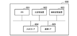
図5は、一実施形態における制御装置のハードウェア構成の一例を示す図である。
コンピュータ900は、CPU901、主記憶装置902、補助記憶装置903、入出力インタフェース904、通信インタフェース905を備える。
上述の制御装置10は、コンピュータ900に実装される。そして、上述した各機能は、プログラムの形式で補助記憶装置903に記憶されている。CPU901は、プログラムを補助記憶装置903から読み出して主記憶装置902に展開し、当該プログラムに従って上記処理を実行する。CPU901は、プログラムに従って、記憶領域を主記憶装置902に確保する。CPU901は、プログラムに従って、処理中のデータを記憶する記憶領域を補助記憶装置903に確保する。
コンピュータ900は、CPU901、主記憶装置902、補助記憶装置903、入出力インタフェース904、通信インタフェース905を備える。
上述の制御装置10は、コンピュータ900に実装される。そして、上述した各機能は、プログラムの形式で補助記憶装置903に記憶されている。CPU901は、プログラムを補助記憶装置903から読み出して主記憶装置902に展開し、当該プログラムに従って上記処理を実行する。CPU901は、プログラムに従って、記憶領域を主記憶装置902に確保する。CPU901は、プログラムに従って、処理中のデータを記憶する記憶領域を補助記憶装置903に確保する。
制御装置10の全部または一部の機能を実現するためのプログラムをコンピュータ読み取り可能な記録媒体に記録して、この記録媒体に記録されたプログラムをコンピュータシステムに読み込ませ、実行することにより各機能部による処理を行ってもよい。ここでいう「コンピュータシステム」とは、OSや周辺機器等のハードウェアを含むものとする。「コンピュータシステム」は、WWWシステムを利用している場合であれば、ホームページ提供環境(あるいは表示環境)も含むものとする。「コンピュータ読み取り可能な記録媒体」とは、CD、DVD、USB等の可搬媒体、コンピュータシステムに内蔵されるハードディスク等の記憶装置のことをいう。このプログラムが通信回線によってコンピュータ900に配信される場合、配信を受けたコンピュータ900が当該プログラムを主記憶装置902に展開し、上記処理を実行しても良い。上記プログラムは、前述した機能の一部を実現するためのものであっても良く、さらに前述した機能をコンピュータシステムにすでに記録されているプログラムとの組み合わせで実現できるものであってもよい。
以上のとおり、本開示に係るいくつかの実施形態を説明したが、これら全ての実施形態は、例として提示したものであり、発明の範囲を限定することを意図していない。これらの実施形態は、その他の様々な形態で実施されることが可能であり、発明の要旨を逸脱しない範囲で種々の省略、置き換え、変更を行うことができる。これらの実施形態及びその変形は、発明の範囲や要旨に含まれると同様に、特許請求の範囲に記載された発明とその均等の範囲に含まれる。
<付記>
各実施形態に記載の制御装置10、電動圧縮機20、リップル電圧の検出方法及びプログラムは、例えば以下のように把握される。
各実施形態に記載の制御装置10、電動圧縮機20、リップル電圧の検出方法及びプログラムは、例えば以下のように把握される。
(1)第1の態様に係る制御装置10は、バッテリ1で駆動する電動圧縮機20の入力電圧の電圧値を不等間隔にサンプリングする取得部101と、不等間隔にサンプリングされた前記電圧値に基づいて、前記入力電圧のリップル成分の波形を演算する波形演算部102と、を備える。
制御装置10によれば、リップル電圧の周波数に関わらず、リップル電圧の振動状況を検出することができる。これにより、リップル電圧の異常を漏れなく検出し、リップル電圧の異常による共振の発生を回避することができる。
(2)第2の態様に係る制御装置10は、(1)の制御装置10であって、前記取得部101は、所定の単位時間(Tp、Tq)を不等間隔に分割するよう定められた複数の時点(点P1~P11、点Q1~Q11)で前記サンプリングを行い、前記波形演算部102は、前記単位時間ごとに前記波形を演算する。
波形の演算に必要な数の電圧値のサンプルが得られる時間を単位時間と定め、その単位時間内で不等間隔に電圧値をサンプリングできるように定めることで、漏れの無いリップル電圧の検出を実現することができる。
波形の演算に必要な数の電圧値のサンプルが得られる時間を単位時間と定め、その単位時間内で不等間隔に電圧値をサンプリングできるように定めることで、漏れの無いリップル電圧の検出を実現することができる。
(3)第3の態様に係る制御装置10は、(1)の制御装置10であって、前記取得部101は、所定の単位時間(Tp、Tq)ごとに、該単位時間を不等間隔に分割する複数の時点を定めて該時点(点P1~P11、点Q1~Q11)ごとに前記サンプリングを行い、前記波形演算部102は、前記単位時間ごとに前記波形を演算する。
サンプリング間隔を様々に変化させることで、リップル電圧の周期とサンプリング周期が重なることによるリップル電圧の検出漏れのリスクを低減することができる。
サンプリング間隔を様々に変化させることで、リップル電圧の周期とサンプリング周期が重なることによるリップル電圧の検出漏れのリスクを低減することができる。
(4)第4の態様に係る制御装置10は、(1)~(3)の制御装置10であって、前記波形が示すリップル電圧の値Wが所定の閾値α以上かどうかを判定する判定部103と、前記リップル電圧の値Wが前記閾値α以上の場合、前記電動圧縮機20のモータ9の回転数を低下させる制御部104と、をさらに備える。
異常なリップル電圧が検出された場合、モータ9の回転数を低下(停止を含む)させることで、共振の発生を回避することができる。
異常なリップル電圧が検出された場合、モータ9の回転数を低下(停止を含む)させることで、共振の発生を回避することができる。
(5)第5の態様に係る電動圧縮機20は、(1)~(4)の制御装置10を備える。
(6)第6の態様に係るリップル電圧の検出方法は、バッテリ1で駆動する電動圧縮機20の入力電圧の電圧値を不等間隔にサンプリングし、不等間隔にサンプリングされた前記電圧値に基づいて、前記入力電圧のリップル成分の波形を演算する。
(7)第7の態様に係るプログラムは、コンピュータを、バッテリで駆動する電動圧縮機の入力電圧の電圧値を不等間隔にサンプリングする手段、不等間隔にサンプリングされた前記電圧値に基づいて、前記入力電圧のリップル成分の波形を演算する手段、として機能させる。
上述の制御装置、電動圧縮機、リップル電圧の検出方法及びプログラムによれば、リップル電圧の異常を確実に検出することができる。
1・・・バッテリ
2・・・コンデンサ
3・・・インバータ
4・・・負荷
5a、5b・・・インダクタ
6・・・コンデンサ
7・・・インバータ
8・・・電源回路
9・・・モータ
10・・・制御装置
101・・・取得部
102・・・波形演算部
103・・・判定部
104・・・制御部
11・・・電圧計
12・・・圧縮部
13・・・記憶装置
20・・・電動圧縮機
30・・・車両空調機
40・・・車両機器
900・・・コンピュータ
901・・・CPU
902・・・主記憶装置
903・・・補助記憶装置
904・・・入出力インタフェース
905・・・通信インタフェース
2・・・コンデンサ
3・・・インバータ
4・・・負荷
5a、5b・・・インダクタ
6・・・コンデンサ
7・・・インバータ
8・・・電源回路
9・・・モータ
10・・・制御装置
101・・・取得部
102・・・波形演算部
103・・・判定部
104・・・制御部
11・・・電圧計
12・・・圧縮部
13・・・記憶装置
20・・・電動圧縮機
30・・・車両空調機
40・・・車両機器
900・・・コンピュータ
901・・・CPU
902・・・主記憶装置
903・・・補助記憶装置
904・・・入出力インタフェース
905・・・通信インタフェース
Claims (7)
- バッテリで駆動する電動圧縮機の入力電圧の電圧値を不等間隔にサンプリングする取得部と、
不等間隔にサンプリングされた前記電圧値に基づいて、前記入力電圧のリップル成分の波形を演算する波形演算部と、
を備える制御装置。 - 前記取得部は、所定の単位時間を不等間隔に分割するよう定められた複数の時点で前記サンプリングを行い、
前記波形演算部は、前記単位時間ごとに前記波形を演算する、
請求項1に記載の制御装置。 - 前記取得部は、所定の単位時間ごとに、該単位時間を不等間隔に分割する複数の時点を定めて該時点ごとに前記サンプリングを行い、
前記波形演算部は、前記単位時間ごとに前記波形を演算する、
請求項1に記載の制御装置。 - 前記波形が示すリップル電圧の値が所定の閾値以上かどうかを判定する判定部と、
前記リップル電圧の値が前記閾値以上の場合、前記電動圧縮機のモータの回転数を低下させる制御部と、
をさらに備える請求項1から請求項3の何れか1項に記載の制御装置。 - 請求項1から請求項4の何れか1項に記載の制御装置を備える、電動圧縮機。
- バッテリで駆動する電動圧縮機の入力電圧の電圧値を不等間隔にサンプリングし、
不等間隔にサンプリングされた前記電圧値に基づいて、前記入力電圧のリップル成分の波形を演算する、
リップル電圧の検出方法。 - コンピュータを、
バッテリで駆動する電動圧縮機の入力電圧の電圧値を不等間隔にサンプリングする手段、
不等間隔にサンプリングされた前記電圧値に基づいて、前記入力電圧のリップル成分の波形を演算する手段、
として機能させるためのプログラム。
Priority Applications (3)
| Application Number | Priority Date | Filing Date | Title |
|---|---|---|---|
| US17/766,939 US12143046B2 (en) | 2019-10-24 | 2020-10-20 | Control device, electric compressor, ripple voltage detecting method, and program |
| CN202410499821.8A CN118188451A (zh) | 2019-10-24 | 2020-10-20 | 控制装置、电动压缩机、脉动电压的检测方法及记录介质 |
| CN202080070825.4A CN114585814B (zh) | 2019-10-24 | 2020-10-20 | 控制装置、电动压缩机、脉动电压的检测方法及记录介质 |
Applications Claiming Priority (2)
| Application Number | Priority Date | Filing Date | Title |
|---|---|---|---|
| JP2019-193693 | 2019-10-24 | ||
| JP2019193693A JP7443020B2 (ja) | 2019-10-24 | 2019-10-24 | 制御装置、電動圧縮機、リップル電圧の検出方法及びプログラム |
Publications (1)
| Publication Number | Publication Date |
|---|---|
| WO2021079880A1 true WO2021079880A1 (ja) | 2021-04-29 |
Family
ID=75620571
Family Applications (1)
| Application Number | Title | Priority Date | Filing Date |
|---|---|---|---|
| PCT/JP2020/039408 Ceased WO2021079880A1 (ja) | 2019-10-24 | 2020-10-20 | 制御装置、電動圧縮機、リップル電圧の検出方法及びプログラム |
Country Status (4)
| Country | Link |
|---|---|
| US (1) | US12143046B2 (ja) |
| JP (2) | JP7443020B2 (ja) |
| CN (2) | CN114585814B (ja) |
| WO (1) | WO2021079880A1 (ja) |
Cited By (1)
| Publication number | Priority date | Publication date | Assignee | Title |
|---|---|---|---|---|
| CN114370727A (zh) * | 2021-12-28 | 2022-04-19 | 青岛海尔空调电子有限公司 | 压缩机控制方法、控制装置及空调器 |
Families Citing this family (2)
| Publication number | Priority date | Publication date | Assignee | Title |
|---|---|---|---|---|
| JPWO2023100321A1 (ja) * | 2021-12-02 | 2023-06-08 | ||
| CN116073738A (zh) * | 2023-02-22 | 2023-05-05 | 浙江联控技术有限公司 | 电动压缩机的控制方法、装置、车辆及存储介质 |
Citations (4)
| Publication number | Priority date | Publication date | Assignee | Title |
|---|---|---|---|---|
| JPH03261838A (ja) * | 1990-03-12 | 1991-11-21 | Nippondenso Co Ltd | エンジン用吸気圧測定装置 |
| JPH10285990A (ja) * | 1997-03-31 | 1998-10-23 | Mitsubishi Electric Corp | 電動機の制御装置および圧縮機 |
| JP2003075205A (ja) * | 2001-09-03 | 2003-03-12 | Taisei Corp | データの収録方法 |
| JP2016036200A (ja) * | 2014-08-01 | 2016-03-17 | 株式会社デンソー | 車両用電動圧縮機 |
Family Cites Families (20)
| Publication number | Priority date | Publication date | Assignee | Title |
|---|---|---|---|---|
| GB1178935A (en) * | 1967-09-13 | 1970-01-21 | Philips Electronic Associated | Low-Frequency Generator |
| US4112339A (en) * | 1977-07-21 | 1978-09-05 | General Electric Company | Measurement of pulsating torque in a current source inverter motor drive |
| WO1990003582A1 (en) * | 1988-09-30 | 1990-04-05 | Zion Educational Foundation | Voltage, current and frequency measuring of non-standard waveforms |
| JPH02206398A (ja) * | 1989-02-04 | 1990-08-16 | Toyo Electric Mfg Co Ltd | インバータ制御方式 |
| JP2669284B2 (ja) * | 1992-12-02 | 1997-10-27 | オムロン株式会社 | 直流モータによって駆動される移動体の位置検出装置および方法 |
| DE4426764C2 (de) * | 1994-07-23 | 1997-06-05 | Licentia Gmbh | Verfahren zur Ansteuerung eines Pulswechselrichters durch Stellbefehle eines Pulsmustergenerators |
| JP3585804B2 (ja) | 2000-03-06 | 2004-11-04 | 三菱電機株式会社 | 方向判別方法 |
| JP3833600B2 (ja) | 2002-10-08 | 2006-10-11 | 三菱電機株式会社 | 車両用交流発電機故障判定装置 |
| JP4173724B2 (ja) * | 2002-12-12 | 2008-10-29 | シャープ株式会社 | モータのトルク制御装置 |
| JP4116451B2 (ja) | 2003-01-10 | 2008-07-09 | 日本特殊陶業株式会社 | 静電容量測定装置及び正弦波振幅検出装置 |
| JP5091521B2 (ja) * | 2007-03-29 | 2012-12-05 | 三菱重工業株式会社 | 一体型電動圧縮機 |
| US7952308B2 (en) * | 2008-04-04 | 2011-05-31 | GM Global Technology Operations LLC | Method and apparatus for torque ripple reduction |
| JP5230250B2 (ja) * | 2008-04-24 | 2013-07-10 | 三菱電機株式会社 | 電動機および電力供給制御装置 |
| JP5326429B2 (ja) * | 2008-08-26 | 2013-10-30 | 株式会社明電舎 | 電動機の脈動抑制装置 |
| JP5332400B2 (ja) * | 2008-08-26 | 2013-11-06 | 株式会社明電舎 | 電動機のトルク脈動抑制装置および抑制方法 |
| DE102008042805A1 (de) * | 2008-10-14 | 2010-04-15 | Robert Bosch Gmbh | Motorsystem sowie Verfahren zum Betreiben eines Motorsystems |
| JP2010284017A (ja) * | 2009-06-05 | 2010-12-16 | Toyota Motor Corp | 交流電動機の制御装置 |
| CN101603526A (zh) * | 2009-07-09 | 2009-12-16 | 宁波速沸电子科技有限公司 | 一种电磁泵、电磁泵的流量控制装置和流量控制方法 |
| EP2908416B1 (en) * | 2013-12-24 | 2020-12-02 | LG Electronics Inc. | Motor driving device and air conditioner including the same |
| CN106385215B (zh) * | 2016-09-27 | 2018-10-26 | 华中科技大学 | 一种交流电机变开关频率pwm转矩脉动控制方法 |
-
2019
- 2019-10-24 JP JP2019193693A patent/JP7443020B2/ja active Active
-
2020
- 2020-10-20 CN CN202080070825.4A patent/CN114585814B/zh active Active
- 2020-10-20 WO PCT/JP2020/039408 patent/WO2021079880A1/ja not_active Ceased
- 2020-10-20 CN CN202410499821.8A patent/CN118188451A/zh active Pending
- 2020-10-20 US US17/766,939 patent/US12143046B2/en active Active
-
2023
- 2023-12-13 JP JP2023210252A patent/JP7621454B2/ja active Active
Patent Citations (4)
| Publication number | Priority date | Publication date | Assignee | Title |
|---|---|---|---|---|
| JPH03261838A (ja) * | 1990-03-12 | 1991-11-21 | Nippondenso Co Ltd | エンジン用吸気圧測定装置 |
| JPH10285990A (ja) * | 1997-03-31 | 1998-10-23 | Mitsubishi Electric Corp | 電動機の制御装置および圧縮機 |
| JP2003075205A (ja) * | 2001-09-03 | 2003-03-12 | Taisei Corp | データの収録方法 |
| JP2016036200A (ja) * | 2014-08-01 | 2016-03-17 | 株式会社デンソー | 車両用電動圧縮機 |
Cited By (2)
| Publication number | Priority date | Publication date | Assignee | Title |
|---|---|---|---|---|
| CN114370727A (zh) * | 2021-12-28 | 2022-04-19 | 青岛海尔空调电子有限公司 | 压缩机控制方法、控制装置及空调器 |
| WO2023124012A1 (zh) * | 2021-12-28 | 2023-07-06 | 青岛海尔空调电子有限公司 | 压缩机控制方法、控制装置及空调器 |
Also Published As
| Publication number | Publication date |
|---|---|
| CN118188451A (zh) | 2024-06-14 |
| CN114585814B (zh) | 2024-05-17 |
| US20240079985A1 (en) | 2024-03-07 |
| CN114585814A (zh) | 2022-06-03 |
| JP2021067232A (ja) | 2021-04-30 |
| JP7443020B2 (ja) | 2024-03-05 |
| JP7621454B2 (ja) | 2025-01-24 |
| JP2024026362A (ja) | 2024-02-28 |
| US12143046B2 (en) | 2024-11-12 |
Similar Documents
| Publication | Publication Date | Title |
|---|---|---|
| JP7621454B2 (ja) | 制御装置、電動圧縮機、リップル電圧の検出方法及びプログラム | |
| US9595906B2 (en) | Motor control apparatus having function for protecting LCL filter | |
| JP2016005317A (ja) | 充電抵抗の保護手段を有するモータ制御装置 | |
| US12326145B2 (en) | Control device, electric compressor, control method, and program | |
| US12126291B2 (en) | Control device, electric compressor, ripple voltage abnormality cause determination method and program | |
| JP6420381B2 (ja) | モータ駆動装置 | |
| JP4661744B2 (ja) | 車両用モーター制御装置 | |
| CN114353299B (zh) | 空调系统的控制方法及空调系统 | |
| JP5339985B2 (ja) | 直流電動機駆動用のインバータ制御装置 | |
| JP2017118714A (ja) | モータ温度及びアンプ温度に応じて動作を変更する機能を有する工作機械の制御装置 | |
| JP2015159646A (ja) | モータ制御システム | |
| JP7031757B2 (ja) | 電力変換装置、圧送装置、制御方法、診断装置及び診断方法 | |
| JP5166112B2 (ja) | モータ駆動用インバータ制御装置 | |
| JP2019097244A (ja) | モータ制御装置及びこれを備えた電動圧縮機、移動体用の空気調和機、モータ制御方法及びモータ制御プログラム | |
| JP2013024150A (ja) | 空気調和装置 | |
| US9790944B2 (en) | Motor-driven compressor with switching element | |
| EP2736165A1 (en) | Power converter | |
| CN118915854A (zh) | 一种座舱域控制器的温度控制方法和相关设备 | |
| JP2017108562A (ja) | 車両用制御装置 | |
| JP2008199766A (ja) | 電動機制御装置 | |
| JP2013090518A (ja) | 自動車 | |
| JP2013230059A (ja) | 発電システム、制御装置、故障検出方法、およびプログラム | |
| JP2009153330A (ja) | 電動ファンの制御装置 |
Legal Events
| Date | Code | Title | Description |
|---|---|---|---|
| 121 | Ep: the epo has been informed by wipo that ep was designated in this application |
Ref document number: 20879873 Country of ref document: EP Kind code of ref document: A1 |
|
| WWE | Wipo information: entry into national phase |
Ref document number: 17766939 Country of ref document: US |
|
| NENP | Non-entry into the national phase |
Ref country code: DE |
|
| 122 | Ep: pct application non-entry in european phase |
Ref document number: 20879873 Country of ref document: EP Kind code of ref document: A1 |