WO2021075507A1 - 吸収体 - Google Patents
吸収体 Download PDFInfo
- Publication number
- WO2021075507A1 WO2021075507A1 PCT/JP2020/038949 JP2020038949W WO2021075507A1 WO 2021075507 A1 WO2021075507 A1 WO 2021075507A1 JP 2020038949 W JP2020038949 W JP 2020038949W WO 2021075507 A1 WO2021075507 A1 WO 2021075507A1
- Authority
- WO
- WIPO (PCT)
- Prior art keywords
- water
- absorbent resin
- resin particles
- region
- seconds
- Prior art date
Links
Images


Classifications
-
- A—HUMAN NECESSITIES
- A61—MEDICAL OR VETERINARY SCIENCE; HYGIENE
- A61F—FILTERS IMPLANTABLE INTO BLOOD VESSELS; PROSTHESES; DEVICES PROVIDING PATENCY TO, OR PREVENTING COLLAPSING OF, TUBULAR STRUCTURES OF THE BODY, e.g. STENTS; ORTHOPAEDIC, NURSING OR CONTRACEPTIVE DEVICES; FOMENTATION; TREATMENT OR PROTECTION OF EYES OR EARS; BANDAGES, DRESSINGS OR ABSORBENT PADS; FIRST-AID KITS
- A61F13/00—Bandages or dressings; Absorbent pads
- A61F13/15—Absorbent pads, e.g. sanitary towels, swabs or tampons for external or internal application to the body; Supporting or fastening means therefor; Tampon applicators
- A61F13/53—Absorbent pads, e.g. sanitary towels, swabs or tampons for external or internal application to the body; Supporting or fastening means therefor; Tampon applicators characterised by the absorbing medium
- A61F13/531—Absorbent pads, e.g. sanitary towels, swabs or tampons for external or internal application to the body; Supporting or fastening means therefor; Tampon applicators characterised by the absorbing medium having a homogeneous composition through the thickness of the pad
- A61F13/532—Absorbent pads, e.g. sanitary towels, swabs or tampons for external or internal application to the body; Supporting or fastening means therefor; Tampon applicators characterised by the absorbing medium having a homogeneous composition through the thickness of the pad inhomogeneous in the plane of the pad
-
- A—HUMAN NECESSITIES
- A61—MEDICAL OR VETERINARY SCIENCE; HYGIENE
- A61F—FILTERS IMPLANTABLE INTO BLOOD VESSELS; PROSTHESES; DEVICES PROVIDING PATENCY TO, OR PREVENTING COLLAPSING OF, TUBULAR STRUCTURES OF THE BODY, e.g. STENTS; ORTHOPAEDIC, NURSING OR CONTRACEPTIVE DEVICES; FOMENTATION; TREATMENT OR PROTECTION OF EYES OR EARS; BANDAGES, DRESSINGS OR ABSORBENT PADS; FIRST-AID KITS
- A61F13/00—Bandages or dressings; Absorbent pads
- A61F13/15—Absorbent pads, e.g. sanitary towels, swabs or tampons for external or internal application to the body; Supporting or fastening means therefor; Tampon applicators
- A61F13/84—Accessories, not otherwise provided for, for absorbent pads
Definitions
- the present invention relates to an absorber.
- an absorber having an absorbing layer capable of absorbing a liquid is used as an absorbent article for absorbing a liquid containing water as a main component such as urine.
- Patent Document 1 describes an absorbent article having a width direction and a front-rear direction, and having a top sheet, a back sheet, and a first absorbent body provided between them; a plurality of first absorbent bodies are provided. It contains a layer of sheet members, is configured to have a water-absorbent resin between the sheet members and no pulp fibers, and has end regions and a central region located between them on both sides in the width direction; An absorbent article in which a water-absorbent resin having a water absorption rate of 20 seconds or less by the vortex method is arranged in a partial region; and a water-absorbent resin having a water absorption rate of 40 seconds or more by the vortex method is arranged in a central region is disclosed. Has been done.
- absorbent articles such as diapers can absorb more liquid when worn, and that liquid leakage to the outside of the absorbent articles is suppressed.
- An object of the present invention is to provide an absorber that has a high liquid absorption amount when worn by a user and can suppress liquid leakage.
- the absorbent layer has a region ⁇ containing the first water-absorbent resin particles having a swelling power of 5 N or more and a swelling power of 6 seconds or more of 7 N or more, and a first It consists of a region ⁇ that does not contain water-absorbent resin particles.
- the region ⁇ extends in the center of the absorption layer along the longitudinal direction of the absorption layer, and the region ⁇ includes portions extending along the longitudinal direction of the absorption layer on both sides of the region ⁇ in the lateral direction. ..
- the swelling power is measured by the swelling power test performed in the following order of i), ii), iii), iv) and v).
- a cylinder having openings at both ends and having a mesh mounted on one of the openings and having an inner diameter of 20 mm is prepared, and the cylinder is vertically erected with the side on which the mesh is mounted facing downward. Then, 0.1 g of water-absorbent resin particles are uniformly sprayed on the mesh in the cylinder, and a cylindrical jig having a diameter of 19.5 mm is placed on the mesh.
- a glass filter having a thickness of 5 mm is placed in a horizontally installed petri dish, and the glass filter is impregnated with physiological saline to a position slightly below the upper surface thereof.
- An impermeable sheet is placed on the upper surface of the glass filter in which the physiological saline has permeated, and the cylinder containing the water-absorbent resin particles is placed on the impermeable sheet so that the mesh faces downward. Stand vertically.
- the impermeable sheet is removed to start water absorption by the water-absorbent resin particles.
- an absorber that has a high liquid absorption amount when worn by the user and can suppress liquid leakage.
- each component in the composition means the total amount of the plurality of substances present in the composition when a plurality of substances corresponding to each component are present in the composition, unless otherwise specified.
- the absorber includes an absorbent layer containing water-absorbent resin particles.
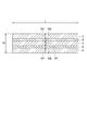
- FIG. 1 is a cross-sectional view in the lateral direction showing an example of an absorber.
- the absorber 50 shown in FIG. 1 has an absorption layer 10 and two core wrap sheets 20a and 20b.
- the core wrap sheets 20a and 20b are arranged on both sides of the absorption layer 10.
- the absorbent layer 10 is arranged inside the core wrap sheets 20a and 20b.
- the absorbent layer 10 is held in shape by being sandwiched between the two core wrap sheets 20a and 20b.
- the core wrap sheets 20a and 20b may be two sheets, one folded sheet, or one bag body.
- the absorption layer 10 includes a region ⁇ containing the first water-absorbent resin particles 10a having a swelling power of 5 N or more and a swelling power of 60 seconds or more of 7 N or more, and a first water-absorbent resin. It consists of a region ⁇ that does not contain the particles 10a.
- the region ⁇ may contain the second water-absorbent resin particles 10b having a swelling power of less than 5 N for 10 seconds or a swelling power of less than 7 N for 60 seconds. It does not have to contain the first and second water-absorbent resin particles).
- the region ⁇ in the absorption layer 10 may be, for example, a void.
- the thickness of the absorption layer 10 is not particularly limited, but may be, for example, 20 mm or less, 15 mm or less, 10 mm or less, 5 mm or less, 4 mm or less, or 3 mm or less in a dry state, and is 0.1 mm or more or 0.3 mm or less. It may be the above.
- the mass per unit area of the absorption layer 10 may be 1000 g / m 2 or less, 800 g / m 2 or less, 600 g / m 2 or less, or 100 g / m 2 or more.
- the absorption layer 10 is composed of a region ⁇ and a region ⁇ , and the thickness of both regions and / or the mass per unit area may be the same or different.
- the water-absorbent resin particles existing in the region ⁇ are the first water-absorbent resin particles having a swelling power of 5 N or more for 10 seconds and a swelling power of 7 N or more for 60 seconds.
- the water-absorbent resin particles present in the region ⁇ have a swelling power of less than 5 N for 10 seconds or a swelling power of less than 7 N for 60 seconds.
- the second water-absorbent resin particles are the first water-absorbent resin particles having a swelling power of 5 N or more for 10 seconds and a swelling power of 7 N or more for 60 seconds.
- the 10-second value of the swelling power and the 60-second value of the swelling power are measured by the swelling power test performed in the order of i), ii), iii), iv) and v) below.
- i) Prepare a cylinder with an inner diameter of 20 mm, which has openings at both ends and has a mesh mounted on one of the openings, with the cylinder standing vertically with the side on which the mesh is mounted facing down.
- 0.1 g of water-absorbent resin particles are uniformly sprayed on the mesh in the cylinder, and a cylindrical jig having a diameter of 19.5 mm is placed on the mesh.
- a glass filter having a thickness of 5 mm is placed in a horizontally installed petri dish, and the glass filter is impregnated with physiological saline to a position slightly below the upper surface thereof.
- An impermeable sheet is placed on the upper surface of a glass filter permeated with physiological saline, and a cylinder containing water-absorbent resin particles is erected vertically on the impermeable sheet with the mesh facing down.
- iv) Remove the impermeable sheet and start water absorption by the water-absorbent resin particles.
- the 10-second value of the swelling power may be 5N or more, 6N or more, 7N or more, 8N or more, 9N or more, 10N or more, or 11N or more, 20N or less, 18N. Hereinafter, it may be 16N or less, 14N or less, or 13N or less.
- the 10-second value of the swelling power may be 5N or more and 20N or less, 5N or more and 18N or less, 5N or more and 16N or less, or 5N or more and 14N or less, or 5N or more and 13N or less.
- the 60-second value of the swelling power may be 7N or more, 9N or more, 11N or more, 13N or more, or 14N or more, and 30N or less, 25N or less, 20N or less, 18N. It may be less than or equal to 16N or less.
- the 60-second value of the swelling power may be 7N or more and 30N or less, 7N or more and 25N or less, 7N or more and 20N or less, 7N or more and 18N or less, or 7N or more and 16N or less.
- the 10-second value of the swelling power may be less than 5N, 4N or less, and 0N or more.
- the 10-second value of the swelling power may be 0N or more and less than 5N, or 0N or more and 4N or less.
- the 60-second value of the swelling force may be less than 7N.
- the 60-second value of the swelling power may be 20 N or less, 16 N or less, 12 N or less, 8 N or less, or 5 N or less.
- the 60-second value of the swelling force may be 0N or more and less than 7N, and may be 0N or more and 20N or less.
- the 10-second value of the swelling force can be determined by, for example, changing the shape of the water-absorbent resin particles to adjust the specific surface area, performing surface treatment to make the surface of the water-absorbent resin hydrophilic, internal cross-linking and surface cross-linking. It can be controlled by adjusting the balance of the light and shade of the cross-linking density in one particle according to the above.
- the 60-second value of the swelling force can be controlled, for example, by adjusting the balance of the light and shade of the cross-linking density in one particle by the internal cross-linking and the surface cross-linking.
- the water absorption amount of the physiological saline of the first water-absorbent resin particles 10a may be, for example, 20 to 80 g / g, 30 to 70 g / g, or 40 to 65 g / g.
- the water absorption rate (Vortex method) of the first water-absorbent resin particles 10a may be, for example, 1 to 70 seconds, 2 to 50 seconds, 2 to 25 seconds, or 2 to 10 seconds.
- the water absorption amount of the physiological saline of the second water-absorbent resin particles 10b may be, for example, 20 to 80 g / g, 30 to 70 g / g, or 40 to 65 g / g.
- the water absorption rate (Vortex method) of the second water-absorbent resin particles 10b may be, for example, 2 to 70 seconds, 15 to 60 seconds, 25 seconds to 50 seconds, or 25 seconds to 40 seconds.
- the water absorption amount and the water absorption rate of the physiological saline can be measured by the method described in Examples described later.
- first water-absorbent resin particles or second water-absorbent resin particles is not particularly limited, and may be, for example, substantially spherical, crushed, or granular, and has these shapes. Particles in which primary particles are aggregated may be formed.
- the medium particle size of the water-absorbent resin particles may be 100 to 800 ⁇ m, 150 to 700 ⁇ m, 200 to 600 ⁇ m, or 250 to 500 ⁇ m.
- the medium particle size can be measured by the following method. From the top, JIS standard sieves have a mesh size of 600 ⁇ m, a mesh size of 500 ⁇ m, a mesh size of 425 ⁇ m, a mesh size of 300 ⁇ m, a mesh size of 250 ⁇ m, a mesh size of 180 ⁇ m, a mesh size of 150 ⁇ m, and a sieve. , Combine in the order of the saucer.
- the mass of the particles remaining on each sieve is calculated as a mass percentage with respect to the total amount to obtain the particle size distribution.
- the relationship between the mesh size of the sieve and the integrated value of the mass percentage of the particles remaining on the sieve is plotted on the logarithmic probability paper by integrating the particles on the sieve in order from the one having the largest particle size with respect to this particle size distribution. By connecting the plots on the probability paper with a straight line, the particle size corresponding to the cumulative mass percentage of 50% by mass is obtained as the medium particle size.
- the water-absorbent resin particles may include, for example, polymer particles formed by polymerization of a monomer containing an ethylenically unsaturated monomer. it can.
- the polymer particles may be water-absorbent particles containing a polymer contained as a monomer unit derived from an ethylenically unsaturated monomer.
- the ethylenically unsaturated monomer may be a water-soluble monomer, and examples thereof include (meth) acrylic acid and salts thereof, 2- (meth) acrylamide-2-methylpropanesulfonic acid and its salts.
- the amino group may be quaternized.
- the ethylenically unsaturated monomer may be used alone or in combination of two or more.
- Functional groups such as the carboxyl group and amino group of the above-mentioned monomers can function as functional groups capable of cross-linking in the surface cross-linking step described later.
- the ethylenically unsaturated monomer may be used alone or in combination of two or more.
- the proportion of the polymer containing the ethylenically unsaturated monomer as a monomer unit in the polymer particles is 50 to 100% by mass, 60 to 100% by mass, and 70 to 100% by mass based on the mass of the polymer particles. , Or 80 to 100% by mass.
- the polymer particles may be particles containing a (meth) acrylic acid-based polymer containing at least one of (meth) acrylic acid or (meth) acrylate as a monomer unit.
- the total ratio of the monomer units derived from (meth) acrylic acid or (meth) acrylate in the (meth) acrylic acid-based polymer may be 70 to 100% by mass based on the mass of the polymer. , 90-100% by mass.
- the water-absorbent resin particles (first water-absorbent resin particles or second water-absorbent resin particles) can be produced by a method including a step of polymerizing a monomer containing an ethylenically unsaturated monomer.
- the polymerization method include a reverse phase suspension polymerization method, an aqueous solution polymerization method, a bulk polymerization method, and a precipitation polymerization method. From the viewpoint of ensuring good water absorption characteristics of the obtained water-absorbent resin particles and facilitating control of the polymerization reaction, a reverse phase suspension polymerization method or an aqueous solution polymerization method may be applied.
- a reverse phase suspension polymerization method will be described as an example.
- the ethylenically unsaturated monomer is at least one selected from the group consisting of (meth) acrylic acid and salts thereof, acrylamide, methacrylamide, and N, N-dimethylacrylamide. It may contain a compound of the species.
- the ethylenically unsaturated monomer may contain (meth) acrylic acid and a salt thereof, and at least one compound selected from the group consisting of acrylamide.
- the ethylenically unsaturated monomer may contain at least one compound selected from the group consisting of (meth) acrylic acid and salts thereof.
- the ethylenically unsaturated monomer can be used in the polymerization reaction as an aqueous solution.
- concentration of the ethylenically unsaturated monomer in the aqueous solution containing the ethylenically unsaturated monomer (hereinafter, simply referred to as "monomeric aqueous solution”) is 20% by mass or more and the saturation concentration or less, 25 to 70% by mass, or 30. It may be up to 55% by mass.
- Examples of the water used in the aqueous solution include tap water, distilled water, ion-exchanged water and the like.
- a monomer other than the above-mentioned ethylenically unsaturated monomer may be used.
- Such a monomer can be used, for example, by mixing with an aqueous solution containing the above-mentioned ethylenically unsaturated monomer.
- the amount of the ethylenically unsaturated monomer used may be 70 to 100 mol% with respect to the total amount of the monomer.
- the ratio of (meth) acrylic acid and a salt thereof may be 70 to 100 mol% with respect to the total amount of the monomer.
- the acidic group may be neutralized with an alkaline neutralizer and then the monomer solution may be used in the polymerization reaction.
- the degree of neutralization of an ethylenically unsaturated monomer by an alkaline neutralizing agent increases the osmotic pressure of the obtained water-absorbent resin particles and further enhances the water absorption characteristics (water absorption amount, etc.). It may be 10-100 mol%, 50-90 mol%, or 60-80 mol% of the acidic group in the body.
- alkaline neutralizing agent examples include alkali metal salts such as sodium hydroxide, sodium carbonate, sodium hydrogen carbonate, potassium hydroxide and potassium carbonate; ammonia and the like.
- the alkaline neutralizer may be used alone or in combination of two or more.
- the alkaline neutralizer may be used in the form of an aqueous solution to simplify the neutralization operation. Neutralization of the acidic group of the ethylenically unsaturated monomer can be performed, for example, by dropping an aqueous solution of sodium hydroxide, potassium hydroxide or the like into the above-mentioned monomer aqueous solution and mixing them.
- an aqueous monomer solution is dispersed in a hydrocarbon dispersion medium in the presence of a surfactant, and an ethylenically unsaturated monomer is polymerized using a radical polymerization initiator or the like.
- a radical polymerization initiator a water-soluble radical polymerization initiator can be used.
- surfactant examples include nonionic surfactants, anionic surfactants and the like.
- nonionic surfactant sorbitan fatty acid ester and (poly) glycerin fatty acid ester (“(poly)” means both with and without the prefix of “poly”. The same shall apply hereinafter.
- Sucrose fatty acid ester polyoxyethylene sorbitan fatty acid ester, polyoxyethylene glycerin fatty acid ester, sorbitol fatty acid ester, polyoxyethylene sorbitol fatty acid ester, polyoxyethylene alkyl ether, polyoxyethylene alkyl phenyl ether, polyoxyethylene himashi
- oil polyoxyethylene hydrogenated castor oil, alkylallyl formaldehyde condensed polyoxyethylene ether, polyoxyethylene polyoxypropylene block copolymer, polyoxyethylene polyoxypropyl alkyl ether, polyethylene glycol fatty acid ester and the like.
- Anionic surfactants include fatty acid salts, alkylbenzene sulfonates, alkylmethyl taurates, polyoxyethylene alkylphenyl ether sulfates, polyoxyethylene alkyl ether sulfonates, and polyoxyethylene alkyl ether phosphates. , And the phosphate ester of polyoxyethylene alkyl allyl ether and the like.
- the surfactant may be used alone or in combination of two or more.
- the surfactant is a sorbitan fatty acid ester. It may contain at least one compound selected from the group consisting of polyglycerin fatty acid ester and sucrose fatty acid ester. From the viewpoint of easily improving the water absorption characteristics of the obtained water-absorbent resin particles, sorbitan fatty acid ester (for example, sorbitan monolaurate) and / or sucrose fatty acid ester (for example, sucrose stearic acid ester) are used as the surfactant. Good. These surfactants may be used alone or in combination of two or more.
- the amount of the surfactant may be 0.05 to 10 parts by mass, 0.08 to 5 parts by mass, or 0.1 to 3 parts by mass with respect to 100 parts by mass of the aqueous monomer solution.
- a polymer-based dispersant may be used in combination with the above-mentioned surfactant.
- the polymer dispersant include maleic anhydride-modified polyethylene, maleic anhydride-modified polypropylene, maleic anhydride-modified ethylene / propylene copolymer, maleic anhydride-modified EPDM (ethylene / propylene / diene / terpolymer), and maleic anhydride.
- the polymer-based dispersant may be used alone or in combination of two or more.
- the polymer-based dispersant includes maleic anhydride-modified polyethylene, maleic anhydride-modified polypropylene, maleic anhydride-modified ethylene / propylene copolymer, and maleic anhydride / ethylene copolymer.
- Maleic anhydride / propylene copolymer, maleic anhydride / ethylene / propylene copolymer, polyethylene, polypropylene, ethylene / propylene copolymer, oxidized polyethylene, oxidized polypropylene, and oxidized ethylene / propylene copolymer It may be at least one selected from the group consisting of.
- the amount of the polymer-based dispersant may be 0.05 to 10 parts by mass, 0.08 to 5 parts by mass, or 0.1 to 3 parts by mass with respect to 100 parts by mass of the aqueous monomer solution.
- the hydrocarbon dispersion medium may contain at least one compound selected from the group consisting of chain aliphatic hydrocarbons having 6 to 8 carbon atoms and alicyclic hydrocarbons having 6 to 8 carbon atoms.
- Hydrocarbon dispersion media include chain aliphatic hydrocarbons such as n-hexane, n-heptane, 2-methylhexane, 3-methylhexane, 2,3-dimethylpentane, 3-ethylpentane, and n-octane; cyclohexane.
- the hydrocarbon dispersion medium may be used alone or in combination of two or more.
- the hydrocarbon dispersion medium may contain at least one selected from the group consisting of n-heptane and cyclohexane.
- the mixture of the above-mentioned hydrocarbon dispersion medium for example, commercially available ExxonHeptane (manufactured by ExxonMobil: containing 75 to 85% of n-heptane and isomeric hydrocarbons) is used. You may.
- the amount of the hydrocarbon dispersion medium is 30 to 1000 parts by mass, 40 to 500 parts by mass, or 50 parts by mass with respect to 100 parts by mass of the monomer aqueous solution from the viewpoint of appropriately removing the heat of polymerization and easily controlling the polymerization temperature. It may be up to 300 parts by mass. When the amount of the hydrocarbon dispersion medium is 30 parts by mass or more, the polymerization temperature tends to be easily controlled. When the amount of the hydrocarbon dispersion medium is 1000 parts by mass or less, the productivity of polymerization tends to be improved, which is economical.
- the radical polymerization initiator may be water-soluble.
- water-soluble radical polymerization initiators include persulfates such as potassium persulfate, ammonium persulfate, and sodium persulfate; methyl ethyl ketone peroxide, methyl isobutyl ketone peroxide, di-t-butyl peroxide, and t-butyl cumylper.
- Peroxides such as oxides, t-butylperoxyacetate, t-butylperoxyisobutyrate, t-butylperoxypivalate, hydrogen peroxide; 2,2'-azobis (2-amidinopropane) dihydrochloride , 2,2'-azobis [2- (N-phenylamidino) propane] dihydrochloride, 2,2'-azobis [2- (N-allylamidino) propane] dihydrochloride, 2,2'-azobis [ 2- (2-imidazolin-2-yl) propane] 2 hydrochloride, 2,2'-azobis ⁇ 2- [1- (2-hydroxyethyl) -2-imidazolin-2-yl] propane ⁇ 2 hydrochloride, 2,2'-azobis ⁇ 2-methyl-N- [1,1-bis (hydroxymethyl) -2-hydroxyethyl] propionamide ⁇ , 2,2'-azobis [2-methyl-N- (2-hydroxy) Ethyl) -propion
- the radical polymerization initiator may be used alone or in combination of two or more. Radical polymerization initiators are potassium persulfate, ammonium persulfate, sodium persulfate, 2,2'-azobis (2-amidinopropane) dihydrochloride, 2,2'-azobis [2- (2-imidazolin-2-yl). ) Propane] 2 hydrochloride and 2,2'-azobis ⁇ 2- [1- (2-hydroxyethyl) -2-imidazolin-2-yl] propane ⁇ 2 hydrochloride, at least one selected from the group. There may be.
- the amount of the radical polymerization initiator may be 0.00005 to 0.01 mol per 1 mol of the ethylenically unsaturated monomer.
- the amount of the radical polymerization initiator used is 0.00005 mol or more, the polymerization reaction does not require a long time and is efficient.
- the amount of the radical polymerization initiator is 0.01 mol or less, it is easy to suppress the occurrence of a rapid polymerization reaction.
- the exemplified radical polymerization initiator can also be used as a redox polymerization initiator in combination with a reducing agent such as sodium sulfite, sodium hydrogen sulfite, ferrous sulfate, and L-ascorbic acid.
- a reducing agent such as sodium sulfite, sodium hydrogen sulfite, ferrous sulfate, and L-ascorbic acid.
- the aqueous monomer solution may contain a chain transfer agent.
- chain transfer agent include hypophosphates, thiols, thiolic acids, secondary alcohols, amines and the like.
- the monomer aqueous solution used for polymerization may contain a thickener in order to control the particle size of the water-absorbent resin particles.
- a thickener examples include hydroxyethyl cellulose, hydroxypropyl cellulose, methyl cellulose, carboxymethyl cellulose, polyacrylic acid, polyethylene glycol, polyacrylamide, polyethyleneimine, dextrin, sodium alginate, polyvinyl alcohol, polyvinylpyrrolidone, polyethylene oxide and the like. If the stirring speed at the time of polymerization is the same, the higher the viscosity of the aqueous monomer solution, the larger the medium particle size of the obtained particles tends to be.
- Cross-linking by self-cross-linking may occur during polymerization, but cross-linking may be further performed by using an internal cross-linking agent.
- an internal cross-linking agent When an internal cross-linking agent is used, it is easy to control the water absorption characteristics of the water-absorbent resin particles.
- the internal cross-linking agent is usually added to the reaction solution during the polymerization reaction.
- the internal cross-linking agent examples include di or tri (meth) acrylic acid esters of polyols such as ethylene glycol, propylene glycol, trimethylolpropane, glycerin, polyoxyethylene glycol, polyoxypropylene glycol, and polyglycerin; Unsaturated polyesters obtained by reacting polyols with unsaturated acids (maleic acid, fumaric acid, etc.); bis (meth) acrylamides such as N, N'-methylenebis (meth) acrylamide; polyepoxides and (meth) Di or tri (meth) acrylic acid esters obtained by reacting with acrylic acid; di (meth) obtained by reacting polyisocyanate (tolylene diisocyanate, hexamethylene diisocyanate, etc.) with hydroxyethyl (meth) acrylate.
- polyols such as ethylene glycol, propylene glycol, trimethylolpropane, glycerin, polyoxyethylene glycol,
- Acrylic acid carbamil esters compounds having two or more polymerizable unsaturated groups such as allylated starch, allylated cellulose, diallyl phthalate, N, N', N "-triallyl isocyanurate, divinylbenzene; Poly such as (poly) ethylene glycol diglycidyl ether, (poly) propylene glycol diglycidyl ether, (poly) glycerin diglycidyl ether, (poly) glycerin triglycidyl ether, (poly) propylene glycol polyglycidyl ether, polyglycerol polyglycidyl ether, etc.
- Poly such as (poly) ethylene glycol diglycidyl ether, (poly) propylene glycol diglycidyl ether, (poly) glycerin diglycidyl ether, (poly) glycerin triglycidyl ether, (poly) propylene
- Glyceridyl compound such as epichlorohydrin, epibromhydrin, ⁇ -methylepichlorohydrin; 2 reactive functional groups such as isocyanate compound (2,4-tolylene diisocyanate, hexamethylene diisocyanate, etc.) Examples thereof include compounds having more than one.
- the internal cross-linking agent may be used alone or in combination of two or more.
- the internal cross-linking agent may be a polyglycidyl compound or diglycidyl. It may be an ether compound.
- the internal cross-linking agent comprises at least one selected from the group consisting of (poly) ethylene glycol diglycidyl ether, (poly) propylene glycol diglycidyl ether, and (poly) glycerin diglycidyl ether. It may be.
- the amount of the internal cross-linking agent is not ethylenically from the viewpoint that the water-soluble property is suppressed by appropriately cross-linking the polymer obtained by the polymerization of the above-mentioned monomer aqueous solution, and a sufficient water absorption amount can be easily obtained. It may be 0 mmol or more, 0.01 mmol or more, 0.015 mmol or more, 0.020 mmol or more, or 0.1 mol or less, per 1 mol of saturated monomer.
- Reversed phase suspension polymerization can be carried out in an aqueous system in oil by heating with stirring in a state where the phases are mixed.
- a monomer aqueous solution containing an ethylenically unsaturated monomer is used as a hydrocarbon dispersion medium in the presence of a surfactant (and, if necessary, a polymer-based dispersant). Disperse in.
- the timing of adding the surfactant, the polymer-based dispersant, or the like may be either before or after the addition of the aqueous monomer solution, as long as it is before the start of the polymerization reaction.
- a surfactant is added after dispersing the monomer aqueous solution in the hydrocarbon dispersion medium in which the polymer-based dispersant is dispersed.
- the polymer may be further dispersed and then polymerized.
- Reverse phase suspension polymerization can be carried out in one stage or in multiple stages of two or more stages. Reversed phase suspension polymerization may be carried out in two or three stages from the viewpoint of increasing productivity.
- an ethylenically unsaturated monomer is added to the reaction mixture obtained in the first step polymerization reaction after the first step reverse phase suspension polymerization is carried out. It may be added and mixed, and the reverse phase suspension polymerization of the second and subsequent steps may be carried out in the same manner as in the first step.
- the above-mentioned radical polymerization initiator is used in the reverse phase suspension polymerization in each stage of the second and subsequent stages.
- the ethylenically unsaturated monomer to be added Based on the amount of the ethylenically unsaturated monomer to be added, it may be added within the range of the molar ratio of each component to the above-mentioned ethylenically unsaturated monomer to carry out reverse phase suspension polymerization.
- an internal cross-linking agent In the reverse phase suspension polymerization in each stage after the second stage, an internal cross-linking agent may be used if necessary.
- an internal cross-linking agent When an internal cross-linking agent is used, it is added within the range of the molar ratio of each component to the above-mentioned ethylenically unsaturated monomer based on the amount of the ethylenically unsaturated monomer provided in each stage, and the suspension is reversed. Muddy polymerization may be carried out.
- the temperature of the polymerization reaction varies depending on the radical polymerization initiator used, but by rapidly advancing the polymerization and shortening the polymerization time, the efficiency is improved and the heat of polymerization is easily removed to carry out the reaction smoothly. From the viewpoint, it may be 20 to 150 ° C. or 40 to 120 ° C.
- the reaction time is usually 0.5-4 hours.
- the completion of the polymerization reaction can be confirmed, for example, by stopping the temperature rise in the reaction system. As a result, the polymer of the ethylenically unsaturated monomer is usually obtained in the state of a hydrogel-like polymer.
- cross-linking may be performed after polymerization by adding a cross-linking agent to the obtained hydrogel polymer and heating it.
- a cross-linking agent to the obtained hydrogel polymer and heating it.
- cross-linking agent for performing post-polymerization cross-linking examples include polyols such as ethylene glycol, propylene glycol, 1,4-butanediol, trimethylolpropane, glycerin, polyoxyethylene glycol, polyoxypropylene glycol, and polyglycerin; Compounds having two or more epoxy groups such as (poly) ethylene glycol diglycidyl ether, (poly) propylene glycol diglycidyl ether, and (poly) glycerin diglycidyl ether; epichlorohydrin, epibromhydrin, ⁇ -methylepicrolhydrin and the like.
- polyols such as ethylene glycol, propylene glycol, 1,4-butanediol, trimethylolpropane
- glycerin polyoxyethylene glycol, polyoxypropylene glycol, and polyglycerin
- Compounds having two or more epoxy groups such as (poly) ethylene glyco
- Haloepoxy compounds compounds having two or more isocyanate groups such as 2,4-tolylene diisocyanate and hexamethylene diisocyanate; oxazoline compounds such as 1,2-ethylene bisoxazoline; carbonate compounds such as ethylene carbonate; bis [N , N-di ( ⁇ -hydroxyethyl)] hydroxyalkylamide compounds such as adipamide can be mentioned.
- Cross-linking agents for post-polymerization cross-linking are (poly) ethylene glycol diglycidyl ether, (poly) glycerin diglycidyl ether, (poly) glycerin triglycidyl ether, (poly) propylene glycol polyglycidyl ether, and polyglycerol polyglycidyl ether. It may be a polyglycidyl compound such as. These cross-linking agents may be used alone or in combination of two or more.
- the amount of the cross-linking agent used for post-polymerization cross-linking is 1 mol of the water-soluble ethylenically unsaturated monomer from the viewpoint of appropriately cross-linking the obtained hydrogel-like polymer to exhibit suitable water absorption characteristics. It may be 0 to 0.03 mol, 0 to 0.01 mol, or 0.00001 to 0.005 mol.
- the cross-linking agent for post-polymerization cross-linking is added to the reaction solution after the polymerization reaction of the ethylenically unsaturated monomer.
- a cross-linking agent for post-polymerization cross-linking may be added after the multi-stage polymerization.
- the cross-linking agent for post-polymerization cross-linking is , From the viewpoint of water content (described later), it may be added in the region of [water content immediately after polymerization ⁇ 3% by mass].
- drying to remove water gives polymer particles containing a polymer of ethylenically unsaturated monomers.
- the drying method include (a) a method of removing water by azeotropic distillation in a state where the hydrogel polymer is dispersed in a hydrocarbon dispersion medium, and (b) a method of taking out the hydrogel polymer by decantation and reducing the pressure. Examples thereof include a method of drying, and (c) a method of filtering the hydrogel polymer by a filter and drying under reduced pressure.
- the particle size of the water-absorbent resin particles can be adjusted by adjusting the rotation speed of the stirrer during the polymerization reaction, or by adding a flocculant into the system after the polymerization reaction or in the early stage of drying. By adding a flocculant, the particle size of the obtained water-absorbent resin particles can be increased.
- an inorganic flocculant can be used as the flocculant.
- the inorganic flocculant for example, powdered inorganic flocculant
- the aggregating agent may be at least one selected from the group consisting of silica (for example, amorphous silica), aluminum oxide, talc and kaolin.
- a coagulant is previously dispersed in a hydrocarbon dispersion medium of the same type as that used in the polymerization or water, and then this is placed in a hydrocarbon dispersion medium containing a hydrogel polymer under stirring. May be mixed with.
- the amount of the flocculant is 0.001 to 1 part by mass, 0.005 to 0.5 part by mass, or 0.01 to 0.2 with respect to 100 parts by mass of the ethylenically unsaturated monomer used for the polymerization. It may be a mass part. When the amount of the flocculant is within these ranges, it is easy to obtain water-absorbent resin particles having a desired particle size distribution.
- the polymerization reaction can be carried out using various stirrers having stirring blades.
- a flat plate blade a lattice blade, a paddle blade, a propeller blade, an anchor blade, a turbine blade, a Faudler blade, a ribbon blade, a full zone blade, a max blend blade and the like can be used.
- the flat plate blade has a shaft (stirring shaft) and a flat plate portion (stirring portion) arranged around the shaft. Further, the flat plate portion may have a slit or the like.
- the cross-linking (surface cross-linking) of the surface portion of the hydrogel polymer may be carried out using a cross-linking agent in any of the drying steps and subsequent steps.
- a cross-linking agent By performing surface cross-linking, it is easy to control the water absorption characteristics of the water-absorbent resin particles.
- the water content of the surface-crosslinked hydrogel polymer may be 5 to 50% by mass, 10 to 40% by mass, or 15 to 35% by mass.
- the amount of water in the hydrogel polymer calculated by adding the amount of water used according to.
- Ws The amount of solid content calculated from the amount of materials such as ethylenically unsaturated monomers, cross-linking agents, and initiators that make up the hydrogel polymer.
- surface cross-linking agents include, for example, polyols such as ethylene glycol, propylene glycol, 1,4-butanediol, trimethylolpropane, glycerin, polyoxyethylene glycol, polyoxypropylene glycol, and polyglycerin; (poly) ethylene.
- Polyglycidyl compounds such as glycol diglycidyl ether, (poly) glycerin diglycidyl ether, (poly) glycerin triglycidyl ether, trimethylpropan triglycidyl ether (poly) propylene glycol polyglycidyl ether, (poly) glycerol polyglycidyl ether; Haloepoxy compounds such as chlorohydrin, epibromhydrin, ⁇ -methylepichlorohydrin; isocyanate compounds such as 2,4-tolylene diisocyanate, hexamethylene diisocyanate; 3-methyl-3-oxetane methanol, 3-ethyl- Oxetane compounds such as 3-oxetane methanol, 3-butyl-3-oxetane methanol, 3-methyl-3-oxetaneethanol, 3-ethyl-3-oxetaneethanol, 3-butyl-3-o
- the surface cross-linking agent may be used alone or in combination of two or more.
- the surface cross-linking agent may be a polyglycidyl compound, and may be (poly) ethylene glycol diglycidyl ether, (poly) glycerin diglycidyl ether, (poly) glycerin triglycidyl ether, (poly) propylene glycol polyglycidyl ether, and poly. It may be at least one selected from the group consisting of glycerol polyglycidyl ether.
- the amount of the surface cross-linking agent used is 0.01 to 20 mmol, 0.05 to 10 mmol, based on 1 mol of the ethylenically unsaturated monomer used for the polymerization, from the viewpoint that suitable water absorption characteristics can be easily obtained. It may be 0.1-5 mmol, 0.15-3 mmol, or 0.2-1 mmol.
- the surface portion of the hydrogel polymer is treated (surface modification) with a surface modifier in either the drying step (moisture removal step) or a subsequent step. May be good.
- the surface modification may be carried out, for example, before, during or after the surface cross-linking step.
- Surface modification may be carried out after surface cross-linking.
- the surface modifier may be, for example, a surfactant such as a nonionic surfactant, an anionic surfactant, a cationic surfactant, or an amphoteric surfactant.
- a surfactant such as a nonionic surfactant, an anionic surfactant, a cationic surfactant, or an amphoteric surfactant.
- the HLB value of the nonionic surfactant used as the surface modifier may be, for example, 3 to 12, or 6 to 10.
- the nonionic surfactant include sorbitan fatty acid esters such as sorbitan monolaurate. The HLB value is measured by the Griffin method.
- the amount of the surface modifier is 0.01 to 0.50 parts by mass, 0.02 to 0.40 parts by mass, or 0.04 with respect to 100 parts by mass of the ethylenically unsaturated monomer used for the polymerization. It may be ⁇ 0.30 parts by mass.
- water and a hydrocarbon dispersion medium can be distilled off from the hydrogel polymer to obtain polymer particles which are dry products. it can.
- the water-absorbent resin particles may be composed of only polymer particles, but may further contain various additional components selected from, for example, a gel stabilizer, a metal chelating agent, a fluidity improver (lubricant), and the like. Can be done. Additional components may be placed inside the polymer particles, on the surface of the polymer particles, or both. The additional component may be a fluidity improver (lubricant).
- the fluidity improver may contain inorganic particles. Examples of the inorganic particles include silica particles such as amorphous silica.
- the water-absorbent resin particles may contain a plurality of inorganic particles arranged on the surface of the polymer particles. For example, by mixing the polymer particles and the inorganic particles, the inorganic particles can be arranged on the surface of the polymer particles.
- the inorganic particles may be silica particles such as amorphous silica.
- the ratio of the amount of the inorganic particles to the mass of the polymer particles is 0.2% by mass or more, 0.5% by mass or more, 1 It may be 0.0% by mass or more, 1.5% by mass or more, 5.0% by mass or less, or 3.5% by mass or less.
- the inorganic particles here usually have a minute size as compared with the size of the polymer particles.
- the average particle size of the inorganic particles may be 0.1 to 50 ⁇ m, 0.5 to 30 ⁇ m, or 1 to 20 ⁇ m.
- the average particle size here can be a value measured by a dynamic light scattering method or a laser diffraction / scattering method.
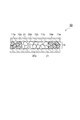
- FIG. 2 is a top view of the strip-shaped absorption layer according to the embodiment.
- the absorption layer 10A shown in FIG. 2 includes a region ⁇ extending in the longitudinal direction of the absorption layer in the center of the absorption layer, and portions extending in the longitudinal direction of the absorption layer on both sides of the region ⁇ in the lateral direction. Includes region ⁇ and.
- FIG. 3 is a top view of the strip-shaped absorbing layer according to another embodiment.
- the region ⁇ extends in the longitudinal direction of the absorption layer on both sides of the region ⁇ in the lateral direction, and the region ⁇ extends in the longitudinal direction of the region ⁇ in the lateral direction of the absorption layer. Includes parts that extend to.
- the region ⁇ has a shape surrounding the region ⁇ .
- the region ⁇ extends from the center of the main surface of the absorption layer to both sides in the longitudinal direction by 2/5 L or more and absorbs. It may be provided in a portion extending 1/8 W or more on both sides in the lateral direction from the center of the main surface of the layer.
- the longitudinal length of the region ⁇ may be the same as the longitudinal length of the absorption layer 10.
- the region ⁇ may be provided along the longitudinal direction of the absorption layer on both sides of the region ⁇ in the lateral direction, and may include a portion extending 1/8 W or more in the lateral direction of the absorption layer.
- the longitudinal direction of the absorbent layer is the direction extending in the anteroposterior direction of the user's crotch when worn by the user, and the lateral direction of the absorbent layer is on the same plane as the main surface of the absorbent layer.
- the direction is orthogonal to the longitudinal direction.
- the liquid to be absorbed first invades the region ⁇ extending along the longitudinal direction in the center of the absorption layer.
- the first absorbent resin particles contained in the region ⁇ swell.
- the liquid was absorbed by arranging the first water-absorbent resin particles having a swelling force of 10 seconds value and 60 seconds value or more, which are indicators reflecting the rapid swelling and the large swelling, in the region ⁇ .
- the phenomenon that the edge of the absorbent layer becomes higher than that of the central part (pocket formation) is likely to occur, and as a result, lateral leakage from the crotch area of the absorbent article (from the region ⁇ ) when worn by the user. It is considered that the leakage of the absorber generated through the region ⁇ from the lateral side can be blocked, and as a result, the liquid leakage is suppressed.
- the factors that suppress liquid leakage are not limited to the above factors.
- the length W of the absorption layer 10 in the lateral direction may be, for example, 5 cm or more, 6 cm or more, or 7 cm or more, and is 18 cm or less, 16 cm or less, 14 cm or less, 12 cm or less, 10 cm. It may be less than or equal to 9 cm or less.
- the length L in the longitudinal direction of the absorption layer may be, for example, 20 cm or more, 22 cm or more, 24 cm or more, or 26 cm or more, and may be 60 cm or less, 50 cm or less, 40 cm or less, 38 cm or less, 36 cm or less, 34 cm or less, 32 cm or less. , Or 30 cm or less.
- the area of the region ⁇ may be 10% or more and 90% or less, 15% or more and 85% or less, and 20% or more and 80% with respect to the area of the main surface of the absorption layer. It may be% or less, and may be 25% or more and 75% or less.
- the area of the region ⁇ may be 10% or more and 90% or less, 15% or more and 85% or less, and 20% or more and 80% with respect to the area of the main surface of the absorption layer. It may be% or less, and may be 25% or more and 75% or less.
- the length W1 of the region ⁇ (the length between the long side of the region ⁇ and the long side of the opposite region ⁇ ) in the lateral direction of the absorption layer is, for example, 0.5 cm or more and 1 cm or more. It may be 5 cm or more, or 2 cm or more, and may be 5.0 cm or less, 4.0 cm or less, 3.5 cm or less, 3.0 cm or less, or 2.5 cm or less.
- the ratio (W1 / W) of the length W1 of the region ⁇ in the lateral direction of the absorbing layer to the length W in the lateral direction of the absorbing layer may be, for example, 1/10 to 3/10.
- the length W2 of the region ⁇ in the lateral direction of the absorption layer may be, for example, 0.5 cm or more, 1 cm or more, 1.5 cm or more, or 2 cm or more, and 5.0 cm or less, 4.0 cm or less, 3 It may be 5.5 cm or less, 3.0 cm or less, or 2.5 cm or less.
- the length W2 (W2 / W) of the region ⁇ in the lateral direction of the absorbing layer with respect to the length W in the lateral direction of the absorbing layer is, for example, 1/10 to 7/10 or 1/5 to 3/5. It may be there.
- the length L1 of the region ⁇ (the length between the short side of the region ⁇ and the short side of the opposite region ⁇ ) in the longitudinal direction of the absorption layer is, for example, 1 cm or more, 1.5 cm or more, and 2 cm. It may be more than or equal to or 3 cm or more, and may be 5.0 cm or less, 4.5 cm or less, 4.0 cm or less, or 2.5 cm or less.
- the ratio (L1 / L) of the length L1 of the region ⁇ in the longitudinal direction of the absorption layer to the length L in the longitudinal direction of the absorption layer is, for example, 2/28 to 5/28 or 3/28 to 4/28. May be.
- the length L2 of the region ⁇ in the longitudinal direction of the absorption layer may be, for example, 18 cm or more, or 20 cm or more, and may be 26 cm or less, 25 cm or less, or 23 cm or less.
- the ratio (L2 / L) of the length L2 of the region ⁇ in the longitudinal direction of the absorption layer to the length L in the longitudinal direction of the absorption layer may be, for example, 18/28 to 25/28.
- the absorption layer 10 may or may not have the fiber layers 11a and 11b containing the fibrous material. That is, the absorption layer 10 may contain fibrous substances and may not substantially contain fibrous substances.
- the content of the fibrous material when substantially free of the fibrous material may be 10% by mass or less, 5% by mass or less, or 0% by mass, based on the mass of the absorbing layer. ..
- the fibrous material constituting the fiber layers 11a and 11b can be, for example, a cellulosic fiber, a synthetic fiber, or a combination thereof.
- cellulosic fibers include crushed wood pulp, cotton, cotton linters, rayon and cellulosic acetate.
- synthetic fibers include polyamide fibers, polyester fibers, and polyolefin fibers.
- the fibrous material may be hydrophilic fibers (for example, pulp).
- the absorption layer 10 may further contain inorganic particles (for example, amorphous silica), a deodorant, an antibacterial agent, a fragrance, and the like.
- inorganic particles for example, amorphous silica
- the absorption layer 10 may contain inorganic particles in addition to the inorganic particles in the water-absorbent resin particles.
- the content of the water-absorbent resin particles in the absorption layer may be 70 to 100% by mass, 80 to 100% by mass, or 90 to 100% by mass based on the mass of the absorption layer 10.
- the core wrap sheets 20a and 20b in the absorber 50 may be, for example, a non-woven fabric.
- the two core wrap sheets 20a and 20b can be the same or different non-woven fabrics.
- the non-woven fabric may be a non-woven fabric composed of short fibers (that is, staples) (short-fiber non-woven fabric) or a non-woven fabric composed of long fibers (that is, filaments) (long-fiber non-woven fabric). Staples are not limited to this, but generally may have a fiber length of several hundred mm or less.
- the core wrap sheets 20a and 20b are laminated including a thermal bond non-woven fabric, an air-through non-woven fabric, a resin bond non-woven fabric, a spunbond non-woven fabric, a melt blow non-woven fabric, an air-laid non-woven fabric, a spunlace non-woven fabric, a point bond non-woven fabric, or two or more kinds of non-woven fabrics selected from these. It can be a body.
- the non-woven fabric used as the core wrap sheets 20a and 20b can be a non-woven fabric formed of synthetic fibers, natural fibers, or a combination thereof.
- synthetic fibers include polyolefins such as polyethylene (PE) and polypropylene (PP), polyesters such as polyethylene terephthalate (PET), polytrimethylene terephthalate (PTT) and polyethylene naphthalate (PEN), polyamides such as nylon, and Examples thereof include fibers containing a synthetic resin selected from rayon.
- Examples of natural fibers include fibers containing cotton, silk, hemp, or pulp (cellulose).
- the fibers forming the non-woven fabric may be polyolefin fibers, polyester fibers or a combination thereof.
- the core wrap sheets 20a and 20b may be tissue paper.
- the core wrap sheets 20a and 20b may have a main surface wider than the main surface of the absorption layer 10. That is, the outer edges of the core wrap sheets 20a and 20b may extend around the absorption layer 10. The core wrap sheets 20a and 20b may be adhered to each other at the outer edge portion extending around the absorption layer 10.
- the absorber 50 may further have an adhesive 21 interposed between the core wrap sheets 20a and 20b and the absorbent layer 10.
- FIG. 4 is a plan view showing an example of an adhesive pattern formed on the core wrap sheet.
- the adhesive 21 shown in FIG. 4 forms a pattern composed of a plurality of linear portions arranged at intervals on the core wrap sheet 20a.
- the pattern of the adhesive 21 is not limited to this.
- An adhesive may be interposed only between one of the core wrap sheets 20a and 20b and the absorbent layer 10.
- the adhesive 21 is not particularly limited, and may be, for example, a hot melt adhesive.
- the absorber 50 is formed by sandwiching, for example, an absorbent layer having a region ⁇ containing the first water-absorbent resin particles and a region ⁇ containing the second water-absorbent resin particles between the core wrap sheets 20a and 20b. It can be obtained by a method of pressurizing the structure while heating it if necessary. If necessary, the adhesive 21 is arranged between the core wrap sheets 20a and 20b and the absorbent layer.
- the absorber 50 is used, for example, to produce various absorbent articles.
- absorbent articles include diapers (eg paper diapers), toilet training pants, incontinence pads, sanitary materials (sanitary napkins, tampons, etc.), sweat pads, pet sheets, toilet components, and animal waste treatment materials. Can be mentioned.
- FIG. 5 is a cross-sectional view showing an example of an absorbent article.
- the absorbent article 100 shown in FIG. 5 includes an absorbent body 50, a liquid permeable sheet 30, and a liquid permeable sheet 40.
- the absorbent body 50 is sandwiched between the liquid permeable sheet 30 and the liquid permeable sheet 40.
- the liquid permeable sheet 30 is arranged at the position of the outermost layer on the side where the liquid to be absorbed enters.
- the liquid permeable sheet 30 is arranged on the outside of the core wrap sheet 20b in contact with the core wrap sheet 20b.
- the liquid permeable sheet 40 is arranged at the position of the outermost layer on the side opposite to the liquid permeable sheet 30 in the absorbent article 100.
- the liquid impermeable sheet 40 is arranged on the outside of the core wrap sheet 20a in a state of being in contact with the core wrap sheet 20a.
- the liquid permeable sheet 30 and the liquid permeable sheet 40 have a main surface wider than the main surface of the absorber 50, and the outer edges of the liquid permeable sheet 30 and the liquid permeable sheet 40 are an absorbent layer.
- the magnitude relationship between the absorbent layer 10, the core wrap sheets 20a and 20b, the liquid permeable sheet 30, and the liquid permeable sheet 40 is not particularly limited, and is appropriately adjusted according to the use of the absorbent article and the like. ..
- the liquid permeable sheet 30 may be a non-woven fabric.
- the non-woven fabric used as the liquid permeable sheet 30 may have appropriate hydrophilicity from the viewpoint of the liquid absorption performance of the absorbent article. From this point of view, the liquid permeable sheet 30 is obtained from the pulp and paper test method No. 1 by the Paper and Pulp Technology Association. A non-woven fabric having a hydrophilicity of 5 to 200 measured according to the measuring method of 68 (2000) may be used. The hydrophilicity of the non-woven fabric may be 10 to 150. Pulp and paper test method No. For details of 68, for example, WO2011 / 086843 can be referred to.
- the non-woven fabric having hydrophilicity may be formed of fibers showing appropriate hydrophilicity such as rayon fiber, or obtained by hydrophilizing a hydrophobic chemical fiber such as polyolefin fiber or polyester fiber. It may be formed of rayon fibers.
- Examples of a method for obtaining a non-woven fabric containing hydrophobic chemical fibers that have been hydrophilized include a method for obtaining a non-woven fabric by a spunbond method using a mixture of hydrophobic chemical fibers and a hydrophilic agent, and hydrophobic chemistry.
- Hydrophilic agents include anionic surfactants such as aliphatic sulfonates and higher alcohol sulfates, cationic surfactants such as quaternary ammonium salts, polyethylene glycol fatty acid esters, polyglycerin fatty acid esters, and sorbitan fatty acids.
- Nonionic surfactants such as esters, silicone-based surfactants such as polyoxyalkylene-modified silicones, and stain-releasing agents made of polyester-based, polyamide-based, acrylic-based, and urethane-based resins are used.
- the amount of texture (mass per unit area) of the non-woven fabric used as the liquid permeable sheet 30 is from the viewpoint of imparting good liquid permeability, flexibility, strength and cushioning property to the absorbent article, and the liquid of the absorbent article. From the viewpoint of increasing the permeation rate, it may be 5 to 200 g / m 2 , 8 to 150 g / m 2 , or 10 to 100 g / m 2 .
- the thickness of the liquid permeable sheet 30 may be 20 to 1400 ⁇ m, 50 to 1200 ⁇ m, or 80 to 1000 ⁇ m.
- the liquid impermeable sheet 40 prevents the liquid absorbed by the absorbing layer 10 from leaking to the outside from the liquid impermeable sheet 40 side.
- the liquid impermeable sheet 40 may be a resin sheet or a non-woven fabric.
- the resin sheet may be a sheet made of a synthetic resin such as polyethylene, polypropylene, or polyvinyl chloride.
- the non-woven fabric may be a spunbond / meltblow / spunbond (SMS) non-woven fabric in which a water-resistant melt-blow non-woven fabric is sandwiched between high-strength spunbond non-woven fabrics.
- SMS spunbond / meltblow / spunbond
- the liquid impermeable sheet 40 may be a composite sheet of a resin sheet and a non-woven fabric (for example, a spunbonded non-woven fabric or a spunlaced non-woven fabric).
- the liquid impermeable sheet 40 may have breathability from the viewpoint that stuffiness at the time of wearing is reduced and discomfort given to the wearer can be reduced.
- a sheet of low density polyethylene (LDPE) resin can be used as the liquid impermeable sheet 40 having breathability.
- the basis weight (mass per unit area) of the liquid impermeable sheet 40 may be 10 to 50 g / m 2.
- the absorbent article 100 can be manufactured, for example, by a method including arranging the absorbent body 50 between the liquid permeable sheet 30 and the liquid permeable sheet 40. A laminate in which the liquid permeable sheet 40, the absorber 50, and the liquid permeable sheet 30 are laminated in this order is pressurized as necessary. Alternatively, the liquid permeable sheet 30, the core wrap sheet 20b, the water-absorbent resin particles 10a, or the mixture containing the water-absorbent resin particles 10a and the fibrous material, and the core wrap sheet 20a and the liquid impermeable sheet 40 are used. The absorbent article 100 can also be obtained by arranging in this order and pressurizing the formed structure while heating if necessary.
- n-heptane as a hydrocarbon dispersion medium
- sorbitan monolaurate Naonion LP-20R, HLB value: 8.6, manufactured by NOF CORPORATION
- the mixture was obtained by addition.
- the sorbitan monolaurate was dissolved in n-heptane by heating the mixture to 50 ° C. while stirring at a stirring speed of 300 rpm, and then the mixture was cooled to 40 ° C.
- the inside of the system was sufficiently replaced with nitrogen. Then, the flask was immersed in a water bath at 70 ° C. and held for 60 minutes to complete the polymerization while stirring at a rotation speed of 700 rpm of the stirrer to obtain a hydrogel polymer.
- amorphous silica (Oriental Silicas Corporation, oriental silicas corporation, etc.) was added to the polymer solution containing the produced hydrogel polymer, n-heptane and a surfactant as a powdery inorganic flocculant.
- the flask containing the reaction solution was immersed in an oil bath at 125 ° C., and 98.0 g of water was extracted from the system while refluxing n-heptane by azeotropic distillation of n-heptane and water. Then, 4.14 g (ethylene glycol diglycidyl ether: 0.475 mmol) of 2% by mass of an ethylene glycol diglycidyl ether aqueous solution was added as a surface cross-linking agent, and the mixture was maintained at an internal temperature of 83 ⁇ 2 ° C. for 2 hours.
- ethylene glycol diglycidyl ether 0.475 mmol
- sorbitan monolaurate trade name: Nonion LP-20R, HLB value 8.6, manufactured by Nichiyu Co., Ltd.
- water and n-heptane were heated in an oil bath at 125 ° C. to evaporate, and dried until almost no evaporation from the system was distilled off to obtain a dried product of polymer particles.
- the polymer particles were passed through a sieve having an opening of 850 ⁇ m to obtain 90.1 g of water-absorbent resin particles a.
- the medium particle size of the water-absorbent resin particles a was 352 ⁇ m.
- Water-absorbent resin particles b 104.0 g of water was extracted from the system by azeotropic distillation, and the surface cross-linking agent was changed to 8.28 g (ethylene glycol diglycidyl ether: 0.951 mmol) of 2% by mass of an ethylene glycol diglycidyl ether aqueous solution. Except for the above, 90.3 g of water-absorbent resin particles b were obtained in the same manner as in Production Example 1. The medium particle size of the water-absorbent resin particles b was 420 ⁇ m.
- the first-stage monomer aqueous solution prepared above was added to the separable flask, and after stirring for 10 minutes, 6.62 g of n-heptane was added as a surfactant to the sucrose stearic acid ester of HLB3. Mitsubishi Chemical Foods Co., Ltd., Ryoto Sugar Ester S-370) 0.736 g of a surfactant solution dissolved by heating is further added, and the inside of the system is sufficiently filled with nitrogen while stirring at a stirring speed of 500 rpm. After the replacement, the flask was immersed in a water bath at 70 ° C. to raise the temperature, and the polymerization was carried out for 60 minutes to obtain a first-stage polymerized slurry solution.
- the entire amount of the monomer aqueous solution in the second stage is added to the polymerized slurry liquid in the first stage.
- the flask was again immersed in a water bath at 70 ° C. to raise the temperature, and the polymerization reaction was carried out for 60 minutes to obtain a hydrogel polymer.
- n-heptane and water were heated in an oil bath at 125 ° C. to evaporate and dry to obtain a dried product of polymer particles.
- the polymer particles are passed through a sieve having an opening of 850 ⁇ m, and 0.2% by mass of amorphous silica (Oriental Silicas Corporation, Toxile NP-S) with respect to the mass of the polymer particles is mixed with the polymer particles.
- amorphous silica Oriental Silicas Corporation, Toxile NP-S
- 231.2 g of water-absorbent resin particles c containing amorphous silica were obtained.
- the medium particle size of the water-absorbent resin particles c was 359 ⁇ m.
- the first-stage monomer aqueous solution prepared above was added to the separable flask, and after stirring for 10 minutes, 6.62 g of n-heptane was added as a surfactant to the sucrose stearic acid ester of HLB3. Mitsubishi Chemical Foods Co., Ltd., Ryoto Sugar Ester S-370) 0.736 g of a surfactant solution dissolved by heating is further added, and the inside of the system is sufficiently filled with nitrogen while stirring at a stirring speed of 550 rpm. After the replacement, the flask was immersed in a water bath at 70 ° C. to raise the temperature, and the polymerization was carried out for 60 minutes to obtain a first-stage polymerized slurry solution.
- the entire amount of the monomer aqueous solution in the second stage is added to the polymerized slurry liquid in the first stage.
- the flask was again immersed in a water bath at 70 ° C. to raise the temperature, and the polymerization reaction was carried out for 60 minutes to obtain a hydrogel polymer.
- n-heptane and water were heated in an oil bath at 125 ° C. to evaporate and dry to obtain a dried product of polymer particles.
- the polymer particles are passed through a sieve having an opening of 850 ⁇ m, and 0.2% by mass of amorphous silica (Oriental Silicas Corporation, Toxile NP-S) with respect to the mass of the polymer particles is mixed with the polymer particles.
- amorphous silica Oriental Silicas Corporation, Toxile NP-S
- 233.0 g of water-absorbent resin particles e containing amorphous silica were obtained.
- the medium particle size of the water-absorbent resin particles e was 128 ⁇ m.
- test absorber The following materials were prepared for the production of test absorbers.
- test absorber provided with an absorbent layer having a length of 28 cm in the longitudinal direction and a length of 8 cm in the lateral direction using the produced water-absorbent resin particles and the above-mentioned material. It was prepared by the method.
- Example 1 The air-laid non-woven fabric was cut into two pieces having a size of 10 cm ⁇ 30 cm to obtain an upper sheet base material and a lower sheet base material of the test absorber.
- Hot melt coating machine (Henkel Co., Ltd., pump: Marshal150, table: XA-DT, tank set temperature: 150 ° C, hose set temperature: 165 ° C, gun head set temperature: 170 ° C) on the lower sheet base material, the total amount
- 10 hot melt adhesives Henkel Japan Ltd., ME-765E
- the adhesive application pattern was a spiral stripe.
- region ⁇ a portion (region ⁇ ) excluding a range of 1 cm at both ends of the lower sheet base material in the lateral direction and the longitudinal direction, 14 cm left and right in the longitudinal direction from the center of the lower sheet substrate, and 2 cm above and below the lateral direction.
- a total of 2.8 g of the water-absorbent resin particles a produced in Production Example 1 were produced in a range (region ⁇ ) of 14 cm to the left and right in the longitudinal direction and 2 cm in the vertical direction from the center of the lower sheet base material.
- 2.8 g of the water-absorbent resin particles c prepared in Example 3 were uniformly sprayed.
- 0.2 g of hot melt adhesive was applied to the upper sheet base material by the same operation as above.
- the surface of the upper sheet base material coated with the hot melt adhesive and the surface of the lower sheet base material coated with the water-absorbent resin particles are aligned at both ends and then sandwiched from above and below with release paper.
- Hashima, Straight Liner Fusion Press, model HP-600LFS they were pressed and bonded under the conditions of 110 ° C. and 0.1 MPa, and the release paper was removed to obtain a test absorber of Example 1.
- an air-laid non-woven fabric, a hot-melt adhesive, an absorbent layer made of water-absorbent resin particles, a hot-melt adhesive, and an air-laid non-woven fabric are arranged in this order.
- the test absorber of Example 1 includes an absorbent layer having the same structure as that of FIG.
- the length W1 in the lateral direction of the region ⁇ (the direction orthogonal to the longitudinal direction of the absorption layer) is 2 cm
- the length W1 in the lateral direction of the region ⁇ (the longitudinal direction of the absorption layer).
- the length W2 in the orthogonal direction) is 4 cm.
- Example 2 A test absorber of Example 2 was obtained in the same manner as in Example 1 except that the water-absorbent resin particles sprayed in the region ⁇ were changed to the water-absorbent resin particles b produced in Production Example 2.
- Example 3 A production example in a portion excluding a range of 1 cm at both ends of the lower sheet base material in the lateral direction and the longitudinal direction as the region ⁇ , 14 cm left and right in the longitudinal direction from the center of the lower sheet substrate, and 3 cm in the vertical direction.
- a total of 1.4 g of the water-absorbent resin particles a produced in 1 was used as a region ⁇ within a range of 14 cm to the left and right in the longitudinal direction and 3 cm in the vertical direction from the center of the lower sheet base material.
- a test absorber of Example 3 was obtained in the same manner as in Example 1 except that 4.2 g of the prepared water-absorbent resin particles c was uniformly sprayed.
- the test absorber of Example 3 includes an absorbent layer having the same structure as that of FIG. In the test absorber of Example 3, the length W1 of the region ⁇ in the lateral direction is 1 cm, and the length W2 of the region ⁇ in the lateral direction is 6 cm.
- Example 4 A production example in a portion excluding a range of 1 cm at both ends of the lower sheet base material in the lateral direction and the longitudinal direction as the region ⁇ , 14 cm left and right in the longitudinal direction from the center of the lower sheet substrate, and 1 cm above and below the lateral direction.
- a total of 5.6 g of the water-absorbent resin particles a prepared in 1 was uniformly sprayed, and the region ⁇ was 14 cm left and right in the longitudinal direction from the center of the lower sheet base material and 1 cm above and below in the lateral direction.
- a test absorber of Example 4 was obtained in the same manner as in Example 1 except that the water-absorbent resin particles were not sprayed.
- the test absorber of Example 4 includes an absorbent layer having the same structure as that of FIG.
- the length W1 of the region ⁇ in the lateral direction is 3 cm
- the length W2 of the region ⁇ in the lateral direction is 2 cm.
- Example 5 A test absorber of Example 5 was obtained in the same manner as in Example 1 except that the upper sheet base material and the lower sheet base material were changed to spunlace non-woven fabric.
- Example 6 A test absorber of Example 6 was obtained in the same manner as in Example 1 except that the upper sheet base material and the lower sheet base material were changed to spunbonded non-woven fabric.
- Example 7 The area ⁇ is the portion excluding the outer circumferences of 1 cm at both ends of the lower sheet base material in the lateral direction and the longitudinal direction, 10.5 cm to the left and right in the longitudinal direction from the center of the lower sheet substrate, and 3 cm in the vertical direction.
- a total of 2.4 g of the water-absorbent resin particles a produced in Production Example 1 were uniformly sprayed, and the region ⁇ was 10.5 cm left and right in the longitudinal direction from the center of the lower sheet base material, and up and down in the lateral direction.
- a test absorber of Example 7 was obtained in the same manner as in Example 1 except that 3.2 g of the water-absorbent resin particles c produced in Production Example 3 was uniformly sprayed in an area of 3 cm.
- the test absorber of Example 7 includes an absorbent layer having the same structure as that of FIG.
- the length W1 of the region ⁇ in the lateral direction of the absorption layer is 1 cm
- the length W2 of the region ⁇ is 6 cm
- the length L1 of the region ⁇ in the longitudinal direction of the absorption layer Is 3.5 cm
- the length L2 of the region ⁇ in the longitudinal direction is 21 cm.
- Comparative Example 1 A test absorber of Comparative Example 1 was obtained in the same manner as in Example 1 except that the water-absorbent resin particles sprayed in the region ⁇ were changed to the water-absorbent resin particles c produced in Production Example 3.
- Comparative Example 2 A test absorber of Comparative Example 2 was obtained in the same manner as in Example 1 except that the water-absorbent resin particles sprayed in the region ⁇ were changed to the water-absorbent resin particles a produced in Production Example 1.
- Comparative Example 3 A test absorber of Comparative Example 3 was obtained in the same manner as in Example 1 except that the water-absorbent resin particles sprayed in the region ⁇ were changed to the water-absorbent resin particles d produced in Production Example 4.
- Comparative Example 4 A test absorber of Comparative Example 4 was obtained in the same manner as in Example 1 except that the water-absorbent resin particles sprayed in the region ⁇ were changed to the water-absorbent resin particles e produced in Production Example 5.
- Comparative Example 5 Examples except that the water-absorbent resin particles sprayed in the region ⁇ were changed to the water-absorbent resin particles f collected from the sanitary napkin "Eris Morning Super Safe CLINICS" (purchased in 2017) of Daio Paper Corporation sold in Japan.
- a test absorber of Comparative Example 5 was obtained in the same manner as in 1.
- Comparative Example 6 A test absorber of Comparative Example 6 was obtained in the same manner as in Example 4 except that the water-absorbent resin particles sprayed on the region ⁇ were changed to the water-absorbent resin particles c produced in Production Example 3.
- the water-absorbent resin particles sprayed on the region ⁇ had a swelling power of less than 5 N for 10 seconds and a swelling power of less than 7 N for 60 seconds (water-absorbing resin particles). It is provided with an absorption layer having the same structure as that of FIG. 2 except that it is a resin particle c).
- the length L1 in the lateral direction of the absorbent layer in the region where the water-absorbent resin particles c were arranged was 3 cm, and the length L1 in the lateral direction of the absorbent layer in the region where the absorbent resin particles were not arranged was 3 cm.
- the length L2 in is 2 cm.
- Comparative Example 7 Manufacturing example in the part excluding the range of 1 cm on the outer circumference of both ends of the lower sheet base material in the lateral direction and the longitudinal direction, 14 cm left and right in the longitudinal direction from the center of the lower sheet base material, and 1 cm to 2 cm in the vertical direction in the lateral direction.
- a total of 5.6 g of the water-absorbent resin particles c prepared in step 3 was uniformly sprayed, and the range was 14 cm from the center of the lower sheet base material to the left and right in the longitudinal direction and 1 cm to 2 cm in the vertical direction.
- a test absorber was obtained in the same manner as in Example 1 except that the water-absorbent resin particles were not sprayed on the portions.
- the water-absorbent resin particles sprayed on the region ⁇ had a swelling power of less than 5 N for 10 seconds and a swelling power of less than 7 N for 60 seconds (water-absorbing resin particles). It is provided with an absorption layer having the same structure as that of FIG. 7 except that it is a resin particle c).
- the length W1 in the lateral direction of the absorbent layer in the region where the water-absorbent resin particles c were arranged was 2 cm
- the length W1 in the lateral direction of the absorbent layer in the region where the absorbent resin particles were not arranged was 2 cm.
- the length W2 in is 1 cm.
- the area ⁇ is the portion excluding the outer circumferences of 1 cm at both ends in the lateral and longitudinal directions of the lower sheet base material, 14 cm left and right from the center of the lower sheet base material in the longitudinal direction, and 1 cm to 2 cm above and below in the lateral direction.
- a total of 5.6 g of the water-absorbent resin particles a produced in Production Example 1 were uniformly sprayed, and the region ⁇ was 14 cm left and right in the longitudinal direction from the center of the lower sheet base material and 1 cm above and below in the lateral direction.
- a test absorber was obtained in the same manner as in Example 1 except that the water-absorbent resin particles were not sprayed on the portion in the range from 1 to 2 cm.
- the test absorber of Comparative Example 8 includes an absorbent layer having the same structure as that of FIG. 7.
- the length W1 of the region ⁇ in the lateral direction of the absorption layer is 2 cm, and the length W2 of the region ⁇ is 1 cm.
- Comparative Example 9 The same as in Example 1 except that the upper sheet base material and the lower sheet base material were changed to a spunlace non-woven fabric, and the water-absorbent resin particles sprayed in the region ⁇ were changed to the water-absorbent resin particles c produced in Production Example 3. , A test absorber was obtained.
- Comparative Example 10 The same as in Example 1 except that the upper sheet base material and the lower sheet base material were changed to a spunbonded non-woven fabric, and the water-absorbent resin particles sprayed in the region ⁇ were changed to the water-absorbent resin particles c produced in Production Example 3. A test absorber was obtained.
- the test absorber of Comparative Example 10 includes an absorbent layer having the same structure as that of FIG.
- the length W1 of the region ⁇ in the lateral direction is 2 cm
- the length W2 of the region ⁇ in the lateral direction is 4 cm.
- the area ⁇ is the portion excluding the outer circumferences of 1 cm at both ends of the lower sheet base material in the lateral direction and the longitudinal direction, 10.5 cm left and right in the longitudinal direction from the center of the lower sheet substrate, and 4 cm in the vertical direction.
- a total of 1.4 g of the water-absorbent resin particles a produced in Production Example 1 was uniformly sprayed, and the region ⁇ was 10.5 cm left and right in the longitudinal direction from the center of the lower sheet base material, and up and down in the lateral direction.
- a test absorber was obtained in the same manner as in Example 1 except that 4.2 g of the water-absorbent resin particles c produced in Production Example 3 was uniformly sprayed in an area of 4 cm.
- the test absorber of Comparative Example 11 includes an absorbent layer having the same structure as that of FIG.
- the length L1 of the region ⁇ in the longitudinal direction of the absorption layer is 3.5 cm
- the length L2 of the region ⁇ is 21 cm.
- the above-mentioned medium particle size of the water-absorbent resin particles was measured by the following procedure. That is, from the top of the JIS standard sieve, a sieve with a mesh size of 600 ⁇ m, a sieve with a mesh size of 500 ⁇ m, a sieve with a mesh size of 425 ⁇ m, a sieve with a mesh size of 300 ⁇ m, a sieve with a mesh size of 250 ⁇ m, a sieve with a mesh size of 180 ⁇ m, and a sieve with a mesh size of 150 ⁇ m. , And the saucer in that order.
- the swelling power test of the water-absorbent resin particles was performed using the apparatus shown in FIG.
- the swelling power test was carried out according to the procedure shown below.
- a small tabletop tester EZ-Test manufactured by Shimadzu Corporation was used to measure the swelling power of the water-absorbent resin particles.
- a cylindrical jig 74 (cylindrical weight) made of acrylic resin having a diameter of 19.5 mm and a height of 59 mm and a mass of 20.5 g is inserted into the cylinder 72, and the cylindrical jig 74 is placed on the water-absorbent resin particles 73.
- a dry glass filter 76 (filter hole diameter G1) having a diameter of 50 mm and a thickness of 5 mm was placed in the central portion of the petri dish 75, and physiological saline 77 was injected to a position slightly below the upper surface of the glass filter 76 ( About 20 ml).
- a 50 mm ⁇ 50 mm impermeable liquid sheet 78 is placed near the center of the upper surface of the glass filter 76 in which the physiological saline 77 has permeated, and the impermeable resin sheet 78 contains the water-absorbent resin particles 73.
- the cylinder 72 was placed vertically with the nylon (registered trademark) mesh 71 facing down.
- the load cell 79 was arranged so that the pressure-sensitive portion having a diameter of 20 mm connected to the load cell 79 of the EZ-Test was located immediately above the cylindrical jig 74 in the cylinder 72.
- FIG. 9 A crotch leak test was performed using the device shown in FIG.
- the device shown in FIG. 9 is a device that imitates a standing position and a sitting position.
- a test absorber is placed on the device, and artificial urine is injected from vertically above the center of the test absorber with a dropping funnel. , The amount of artificial urine leaked from the lateral side of the test absorber is evaluated.
- the aluminum formwork 54 was assembled by assembling aluminum parts 54a and 54b (the width of the aluminum frame is 3 cm) so that the horizontal distance between the insides of the aluminum parts was 15 cm.
- the most slack portion of the impermeable sheet 53 was set at a position 9 cm vertically above the surface (horizontal plane) on which the measuring device was installed.
- Tables 2 and 3 show the conditions and evaluation results of the absorber.
- the amount of spray in the area ⁇ indicates the total value, and the amount in parentheses indicates the amount of spray in one part of the area ⁇ and the amount of spray in the other part.
- the numerical value in the center of is indicated the amount of spraying of the portion provided in the center.
- liquid leakage in the wearing state of the user is suppressed by controlling the position of the absorption layer where the region containing the water-absorbent resin particles whose gel swelling power is a specific value is provided. ..
- the device shown in FIG. 10 is a device that imitates lying on the back and lying down, and is obtained by placing a test absorber and injecting artificial urine toward the center of the test absorber with a liquid feed pump. The amount of leakage is evaluated.
- the test absorber 50 was placed on the U-shaped acrylic instrument 61 so that the center of the test absorber 50 was the center of the instrument, and an arbitrary portion was fixed with tape so as not to shift. ..
- the acrylic instrument 61 is installed on the measuring table 65 in a state of being opened in the horizontal direction, and a point at the center of the test absorber 50 and 1 cm horizontally away from the test absorber 50 is the input point.
- the drainage port (diameter 0.4 cm) of the liquid feed pump 62 (INTERGRA Bioscience AG, model: DOSEI IT P910) for liquid injection was arranged.
- 80 ml of artificial urine adjusted to a liquid temperature of 25 degrees was injected at a rate of 8 ml / sec.
- the artificial urine leaked from the test absorber 50 is collected and weighed in advance by a SUS tray 63 placed in the downward direction of the test absorber 50 and placed on the balance 64.
- Table 4 shows the conditions and evaluation results of the absorber.
- the spraying amount of the portion provided along the longitudinal direction on one side of the region ⁇ was 0.8 g, and the spraying amount was 0.8 g on one side of the region ⁇ .
- the amount of spraying of the portion provided along the lateral direction is 0.4 g
- the portion provided along the longitudinal direction on the other side of the region ⁇ is 0.8 g
- the portion provided along the lateral direction is provided along the lateral direction of the region ⁇ . It is shown that the spraying amount of the portion is 0.4 g.
- the amount in parentheses in Example 3 and Comparative Example 11 indicates the amount of spraying one portion of the region ⁇ / the amount of spraying the other portion of the region ⁇ .
- 10 Absorbent layer, 10a ... First water-absorbent resin particles, 10b ... Second water-absorbent resin particles, 11a, 11b ... Fiber layer, 20a ... Core wrap sheet, 20b ... Core wrap sheet, 21 ... Adhesive, 30 ... Liquid permeable sheet, 40 ... Liquid permeable sheet, 50 ... Absorbent, 100 ... Absorbent article.
Abstract
短冊状の吸収層を備える、吸収体であって、吸収層が、膨潤力の10秒値が5N以上であり、かつ、膨潤力の60秒値が7N以上である第1の吸水性樹脂粒子を含む領域αと、第1の吸水性樹脂粒子を含まない領域βと、からなり、領域βが、吸収層の中央で、吸収層の長手方向に沿って延在し、領域αが、領域βの短手方向における両側で、吸収層の長手方向に沿って延在する部分を含む、吸収体が開示される。
Description
本発明は、吸収体に関する。
尿等の水を主成分とする液体を吸収するための吸収性物品には、昨今では、液体を吸収可能な吸収層を備える吸収体が用いられている。
例えば、特許文献1には、幅方向と前後方向を有し、トップシートとバックシートとこれらの間に設けられた第1吸収体を有する吸収性物品であって;第1吸収体は、複数層のシート部材を含み、シート部材の間に吸水性樹脂を有しパルプ繊維を有しないように構成され、幅方向の両側に端部領域とこれらの間に位置する中央領域を有し;端部領域に、ボルテックス法による吸水速度が20秒以下である吸水性樹脂が配され;中央領域に、ボルテックス法による吸水速度が40秒以上である吸水性樹脂が配されている吸収性物品が開示されている。
おむつ等の吸収性物品は、装着した状態においてより多くの液体を吸収することができ、吸収性物品の外部への液体漏れが抑制されていることが望ましい。
本発明は、使用者の装着状態において高い吸液量を有し、液体漏れを抑制可能な吸収体を提供することを目的とする。
本発明の一側面は、短冊状の吸収層を備える、吸収体に関する。当該吸収体において、吸収層は、膨潤力の10秒値が5N以上であり、かつ、膨潤力の60秒値が7N以上である第1の吸水性樹脂粒子を含む領域αと、第1の吸水性樹脂粒子を含まない領域βと、からなる。領域βは、吸収層の中央で、吸収層の長手方向に沿って延在し、領域αは、領域βの短手方向における両側で、吸収層の長手方向に沿って延在する部分を含む。
膨潤力は、以下のi)、ii)、iii)、iv)及びv)の順で行われる膨潤力試験で測定される。
i)両端に開口部を有し、その一方の開口部にメッシュが装着された内径20mmのシリンダーを用意し、前記メッシュが装着された側を下になる向きで前記シリンダーを垂直に立てた状態で、前記シリンダー内で前記メッシュ上に0.1gの吸水性樹脂粒子を均一に散布し、その上に直径19.5mmの円筒形治具を置く。
ii)厚み5mmのガラスフィルターを、水平に設置されたシャーレ内に載置し、前記ガラスフィルターにその上面より僅かに下の位置まで生理食塩水を浸透させる。
iii)前記生理食塩水が浸透した前記ガラスフィルターの上面に不透液シートを置き、該不透液シートの上に、前記吸水性樹脂粒子を含む前記シリンダーを、前記メッシュが下になる向きで垂直に立てる。
iv)前記不透液シートを取り除いて、前記吸水性樹脂粒子による吸水を開始させる。
v)前記不透液シートを取り除いてから10秒後の時点及び60秒後の時点の、前記吸水性樹脂粒子の膨潤によって生じた前記円筒形治具を押し上げる力をロードセルによって測定し、10秒後の時点の測定値を膨潤力の10秒値として記録し、60秒後の時点の測定値を膨潤力の60秒値として記録する。
本発明によれば、使用者の装着状態において高い吸液量を有し、液体漏れを抑制可能な吸収体を提供することができる。
以下、本発明のいくつかの実施形態について詳細に説明する。ただし、本発明は以下の実施形態に限定されるものではない。
本明細書において、「アクリル」及び「メタクリル」を合わせて「(メタ)アクリル」と表記する。「アクリレート」及び「メタクリレート」も同様に「(メタ)アクリレート」と表記する。本明細書に段階的に記載されている数値範囲において、ある段階の数値範囲の上限値又は下限値は、他の段階の数値範囲の上限値又は下限値と任意に組み合わせることができる。本明細書に記載されている数値範囲において、その数値範囲の上限値又は下限値は、実施例に示されている値に置き換えてもよい。「A又はB」とは、A及びBのどちらか一方を含んでいればよく、両方とも含んでいてもよい。「水溶性」とは、25℃において水に5質量%以上の溶解性を示すことをいう。本明細書に例示する材料は、単独で用いられてもよく、2種以上を組み合わせて用いられてもよい。組成物中の各成分の含有量は、組成物中に各成分に該当する物質が複数存在する場合、特に断らない限り、組成物中に存在する当該複数の物質の合計量を意味する。
<吸収体>
一実施形態に係る吸収体は、吸水性樹脂粒子を含む吸収層を備える。図1は、吸収体の一例を示す短手方向の断面図である。図1に示す吸収体50は、吸収層10と、2枚のコアラップシート20a,20bとを有する。コアラップシート20a,20bは、吸収層10の両側に配置されている。言い換えると、吸収層10は、コアラップシート20a,20bの内側に配置されている。吸収層10は、2枚のコアラップシート20a,20bの間に挟まれることにより、保形されている。コアラップシート20a,20bは、2枚のシートであってもよいし、折り返された1枚のシート、又は1枚の袋体であってもよい。
一実施形態に係る吸収体は、吸水性樹脂粒子を含む吸収層を備える。図1は、吸収体の一例を示す短手方向の断面図である。図1に示す吸収体50は、吸収層10と、2枚のコアラップシート20a,20bとを有する。コアラップシート20a,20bは、吸収層10の両側に配置されている。言い換えると、吸収層10は、コアラップシート20a,20bの内側に配置されている。吸収層10は、2枚のコアラップシート20a,20bの間に挟まれることにより、保形されている。コアラップシート20a,20bは、2枚のシートであってもよいし、折り返された1枚のシート、又は1枚の袋体であってもよい。
[吸収層]
吸収層10は、膨潤力の10秒値が5N以上であり、かつ、膨潤力の60秒値が7N以上である第1の吸水性樹脂粒子10aを含む領域αと、第1の吸水性樹脂粒子10aを含まない領域βからなる。領域βは、膨潤力の10秒値が5N未満であるか、又は、膨潤力の60秒値が7N未満である第2の吸水性樹脂粒子10bを含んでいてもよく、吸水性樹脂粒子(第1及び第2の吸水性樹脂粒子)を含んでいなくてもよい。領域βが吸水性樹脂粒子を含んでいない場合、吸収層10における領域βは、例えば、空隙であってもよい。
吸収層10は、膨潤力の10秒値が5N以上であり、かつ、膨潤力の60秒値が7N以上である第1の吸水性樹脂粒子10aを含む領域αと、第1の吸水性樹脂粒子10aを含まない領域βからなる。領域βは、膨潤力の10秒値が5N未満であるか、又は、膨潤力の60秒値が7N未満である第2の吸水性樹脂粒子10bを含んでいてもよく、吸水性樹脂粒子(第1及び第2の吸水性樹脂粒子)を含んでいなくてもよい。領域βが吸水性樹脂粒子を含んでいない場合、吸収層10における領域βは、例えば、空隙であってもよい。
吸収層10の厚さは、特に限定されないが、乾燥状態で、例えば20mm以下、15mm以下、10mm以下、5mm以下、4mm以下、又は3mm以下であってよく、0.1mm以上、又は0.3mm以上であってもよい。吸収層10の単位面積当たりの質量は、1000g/m2以下、800g/m2以下、又は600g/m2以下であってもよく、100g/m2以上であってもよい。吸収層10は、領域αと領域βとからなり、両領域の厚み、及び/又は単位面積当たりの質量は、同じであってもよく、異なっていてもよい。
(吸水性樹脂粒子)
領域αに存在する吸水性樹脂粒子は、膨潤力の10秒値が5N以上であり、かつ、膨潤力の60秒値が7N以上である、第1の吸水性樹脂粒子である。領域βに吸水性樹脂粒子が存在する場合、領域βに存在する吸水性樹脂粒子は、膨潤力の10秒値が5N未満であるか、又は、膨潤力の60秒値が7N未満である、第2の吸水性樹脂粒子である。
領域αに存在する吸水性樹脂粒子は、膨潤力の10秒値が5N以上であり、かつ、膨潤力の60秒値が7N以上である、第1の吸水性樹脂粒子である。領域βに吸水性樹脂粒子が存在する場合、領域βに存在する吸水性樹脂粒子は、膨潤力の10秒値が5N未満であるか、又は、膨潤力の60秒値が7N未満である、第2の吸水性樹脂粒子である。
膨潤力の10秒値及び膨潤力の60秒値は、以下のi)、ii)、iii)、iv)及びv)の順で行われる膨潤力試験で測定される。
i)両端に開口部を有し、その一方の開口部にメッシュが装着された内径20mmのシリンダーを用意し、メッシュが装着された側を下になる向きでシリンダーを垂直に立てた状態で、シリンダー内でメッシュ上に0.1gの吸水性樹脂粒子を均一に散布し、その上に直径19.5mmの円筒形治具を置く。
ii)厚み5mmのガラスフィルターを、水平に設置されたシャーレ内に載置し、ガラスフィルターにその上面より僅かに下の位置まで生理食塩水を浸透させる。
iii)生理食塩水が浸透したガラスフィルターの上面に不透液シートを置き、該不透液シートの上に、吸水性樹脂粒子を含むシリンダーを、メッシュが下になる向きで垂直に立てる。
iv)不透液シートを取り除いて、吸水性樹脂粒子による吸水を開始させる。
v)不透液シートを取り除いてから10秒後の時点及び60秒後の時点の、吸水性樹脂粒子の膨潤によって生じた円筒形治具を押し上げる力をロードセルによって測定し、10秒後の時点の測定値を膨潤力の10秒値として記録し、60秒後の時点の測定値を膨潤力の60秒値として記録する。膨潤力は、具体的には後述する実施例に記載の方法によって測定される。
第1の吸水性樹脂粒子10aにおいて、膨潤力の10秒値は、5N以上であり、6N以上、7N以上、8N以上、9N以上、10N以上、又は11N以上であってよく、20N以下、18N以下、16N以下、14N以下、又は13N以下であってよい。第1の吸水性樹脂粒子10aにおいて、膨潤力の10秒値は、5N以上20N以下、5N以上18N以下、5N以上16N以下、又は5N以上14N以下、又は5N以上13N以下であってよい。
第1の吸水性樹脂粒子10aにおいて、膨潤力の60秒値は、7N以上であり、9N以上、11N以上、13N以上、又は14N以上であってよく、30N以下、25N以下、20N以下、18N以下、又は16N以下であってよい。第1の吸水性樹脂粒子10aにおいて、膨潤力の60秒値は、7N以上30N以下、7N以上25N以下、7N以上20N以下、7N以上18N以下、又は7N以上16N以下であってよい。
第2の吸水性樹脂粒子10bにおいて、膨潤力の10秒値は、5N未満であってよく、4N以下であってよく、0N以上であってよい。第2の吸水性樹脂粒子10bにおいて、膨潤力の10秒値は、0N以上5N未満、又は0N以上4N以下であってよい。
第2の吸水性樹脂粒子10bにおいて、膨潤力の60秒値は、7N未満であってよい。第2の吸水性樹脂粒子10bにおいて、膨潤力の60秒値は、20N以下、16N以下、12N以下、8N以下、又は5N以下であってもよい。第2の吸水性樹脂粒子10bにおいて、膨潤力の60秒値は、0N以上7N未満であってよく、0N以上20N以下であってもよい。
膨潤力の10秒値は、例えば、吸水性樹脂粒子の形状を変化させ比表面積を調整すること、吸水性樹脂の表面を親水化するような表面処理を施すこと、内部の架橋と表面架橋とによる粒子一粒における架橋密度の濃淡のバランスを調整すること等により、制御することができる。膨潤力の60秒値は、例えば、内部の架橋と表面架橋とによる粒子一粒における架橋密度の濃淡のバランスを調整すること等により、制御することができる。
第1の吸水性樹脂粒子10aの生理食塩水の吸水量は、例えば20~80g/g、30~70g/g、又は40~65g/gであってよい。第1の吸水性樹脂粒子10aの吸水速度(Vortex法)は、例えば1~70秒、2~50秒、2~25秒、又は2~10秒であってよい。
第2の吸水性樹脂粒子10bの生理食塩水の吸水量は、例えば20~80g/g、30~70g/g、又は40~65g/gであってよい。第2の吸水性樹脂粒子10bの吸水速度(Vortex法)は、例えば2~70秒、15~60秒、25秒~50秒、又は25秒~40秒であってよい。
生理食塩水の吸水量及び吸水速度は、後述する実施例に記載の方法により測定することができる。
吸水性樹脂粒子(第1の吸水性樹脂粒子又は第2の吸水性樹脂粒子)の形状は、特に限定されず、例えば略球状、破砕状又は顆粒状であってもよく、これらの形状を有する一次粒子が凝集した粒子が形成されていてもよい。
吸水性樹脂粒子(第1の吸水性樹脂粒子又は第2の吸水性樹脂粒子)の中位粒子径は、100~800μm、150~700μm、200~600μm、又は250~500μmであってもよい。中位粒子径は、以下の方法で測定することができる。JIS標準篩を上から、目開き600μmの篩、目開き500μmの篩、目開き425μmの篩、目開き300μmの篩、目開き250μmの篩、目開き180μmの篩、目開き150μmの篩、及び、受け皿の順に組み合わせる。組み合わせた最上の篩に、吸水性樹脂粒子50gを入れ、ロータップ式振とう器(株式会社飯田製作所製)を用いてJIS Z 8815(1994)に準じて分級する。分級後、各篩上に残った粒子の質量を全量に対する質量百分率として算出し粒度分布を求める。この粒度分布に関して粒子径の大きい方から順に篩上を積算することにより、篩の目開きと篩上に残った粒子の質量百分率の積算値との関係を対数確率紙にプロットする。確率紙上のプロットを直線で結ぶことにより、積算質量百分率50質量%に相当する粒子径を中位粒子径として得る。
吸水性樹脂粒子(第1の吸水性樹脂粒子又は第2の吸水性樹脂粒子)は、例えば、エチレン性不飽和単量体を含む単量体の重合により形成された重合体粒子を含むことができる。重合体粒子は、エチレン性不飽和単量体に由来する単量体単位として含む重合体を含有する吸水性の粒子であってもよい。エチレン性不飽和単量体は、水溶性の単量体であってもよく、その例としては、(メタ)アクリル酸及びその塩、2-(メタ)アクリルアミド-2-メチルプロパンスルホン酸及びその塩、(メタ)アクリルアミド、N,N-ジメチル(メタ)アクリルアミド、2-ヒドロキシエチル(メタ)アクリレート、N-メチロール(メタ)アクリルアミド、ポリエチレングリコールモノ(メタ)アクリレート、N,N-ジエチルアミノエチル(メタ)アクリレート、N,N-ジエチルアミノプロピル(メタ)アクリレート、並びにジエチルアミノプロピル(メタ)アクリルアミドが挙げられる。エチレン性不飽和単量体がアミノ基を有する場合、当該アミノ基は4級化されていてもよい。エチレン性不飽和単量体は、単独で用いられてもよく、2種以上を組み合わせて用いられてもよい。上述の単量体のカルボキシル基、アミノ基等の官能基は、後述する表面架橋工程において架橋が可能な官能基として機能し得る。
エチレン性不飽和単量体は、単独で用いられてもよく、2種以上を組み合わせて用いられてもよい。重合体粒子における、エチレン性不飽和単量体を単量体単位として含む重合体の割合は、重合体粒子の質量を基準として50~100質量%、60~100質量%、70~100質量%、又は80~100質量%であってもよい。重合体粒子は、(メタ)アクリル酸又は(メタ)アクリル酸塩のうち少なくとも一方を単量体単位として含む(メタ)アクリル酸系重合体を含有する粒子であってもよい。(メタ)アクリル酸系重合体における(メタ)アクリル酸又は(メタ)アクリル酸塩に由来する単量体単位の合計の割合は、重合体の質量を基準として70~100質量%であってよく、90~100質量%であってもよい。
吸水性樹脂粒子(第1の吸水性樹脂粒子又は第2の吸水性樹脂粒子)は、エチレン性不飽和単量体を含む単量体を重合させる工程を含む方法により、製造することができる。重合方法としては、逆相懸濁重合法、水溶液重合法、バルク重合法、沈殿重合法等が挙げられる。得られる吸水性樹脂粒子の良好な吸水特性の確保、及び、重合反応の制御が容易である観点から、逆相懸濁重合法又は水溶液重合法を適用してもよい。以下においては、エチレン性不飽和単量体を重合させる方法として、逆相懸濁重合法を例にとって説明する。
工業的に入手が容易である観点から、エチレン性不飽和単量体は、(メタ)アクリル酸及びその塩、アクリルアミド、メタクリルアミド、並びに、N,N-ジメチルアクリルアミドからなる群より選ばれる少なくとも1種の化合物を含んでいてもよい。エチレン性不飽和単量体が、(メタ)アクリル酸及びその塩、並びに、アクリルアミドからなる群より選ばれる少なくとも1種の化合物を含んでいてもよい。吸水特性を更に高める観点から、エチレン性不飽和単量体は、(メタ)アクリル酸及びその塩からなる群より選ばれる少なくとも1種の化合物を含んでもよい。
エチレン性不飽和単量体は、水溶液として重合反応に用いることができる。エチレン性不飽和単量体を含む水溶液(以下、単に「単量体水溶液」という)におけるエチレン性不飽和単量体の濃度は、20質量%以上飽和濃度以下、25~70質量%、又は30~55質量%であってもよい。水溶液において使用される水としては、水道水、蒸留水、イオン交換水等が挙げられる。
吸水性樹脂粒子を得るための単量体として、上述のエチレン性不飽和単量体以外の単量体が使用されてもよい。このような単量体は、例えば、上述のエチレン性不飽和単量体を含む水溶液に混合して用いることができる。エチレン性不飽和単量体の使用量は、単量体全量に対して70~100モル%であってもよい。(メタ)アクリル酸及びその塩の割合が単量体全量に対して70~100モル%であってもよい。
エチレン性不飽和単量体が酸性基を有する場合、その酸性基をアルカリ性中和剤によって中和してから、単量体溶液を重合反応に用いてもよい。エチレン性不飽和単量体における、アルカリ性中和剤による中和度は、得られる吸水性樹脂粒子の浸透圧を高くし、吸水特性(吸水量等)を更に高める観点から、エチレン性不飽和単量体中の酸性基の10~100モル%、50~90モル%、又は60~80モル%であってもよい。アルカリ性中和剤としては、水酸化ナトリウム、炭酸ナトリウム、炭酸水素ナトリウム、水酸化カリウム、炭酸カリウム等のアルカリ金属塩;アンモニアなどが挙げられる。アルカリ性中和剤は、単独で用いられてもよく、2種以上を組み合わせて用いられてもよい。アルカリ性中和剤は、中和操作を簡便にするために水溶液の状態で用いられてもよい。エチレン性不飽和単量体の酸性基の中和は、例えば、水酸化ナトリウム、水酸化カリウム等の水溶液を上述の単量体水溶液に滴下して混合することにより行うことができる。
逆相懸濁重合法においては、界面活性剤の存在下、炭化水素分散媒中で単量体水溶液を分散し、ラジカル重合開始剤等を用いてエチレン性不飽和単量体の重合を行うことができる。ラジカル重合開始剤としては、水溶性ラジカル重合開始剤を用いることができる。
界面活性剤としては、ノニオン系界面活性剤、アニオン系界面活性剤等が挙げられる。ノニオン系界面活性剤としては、ソルビタン脂肪酸エステル、(ポリ)グリセリン脂肪酸エステル(「(ポリ)」とは、「ポリ」の接頭語がある場合及びない場合の双方を意味するものとする。以下同じ。)、ショ糖脂肪酸エステル、ポリオキシエチレンソルビタン脂肪酸エステル、ポリオキシエチレングリセリン脂肪酸エステル、ソルビトール脂肪酸エステル、ポリオキシエチレンソルビトール脂肪酸エステル、ポリオキシエチレンアルキルエーテル、ポリオキシエチレンアルキルフェニルエーテル、ポリオキシエチレンヒマシ油、ポリオキシエチレン硬化ヒマシ油、アルキルアリルホルムアルデヒド縮合ポリオキシエチレンエーテル、ポリオキシエチレンポリオキシプロピレンブロックコポリマー、ポリオキシエチレンポリオキシプロピルアルキルエーテル、ポリエチレングリコール脂肪酸エステル等が挙げられる。アニオン系界面活性剤としては、脂肪酸塩、アルキルベンゼンスルホン酸塩、アルキルメチルタウリン酸塩、ポリオキシエチレンアルキルフェニルエーテル硫酸エステル塩、ポリオキシエチレンアルキルエーテルスルホン酸塩、ポリオキシエチレンアルキルエーテルのリン酸エステル、及びポリオキシエチレンアルキルアリルエーテルのリン酸エステル等が挙げられる。界面活性剤は、単独で用いられてもよく、2種以上を組み合わせて用いられてもよい。
W/O型逆相懸濁の状態が良好であり、好適な粒子径を有する吸水性樹脂粒子が得られやすく、工業的に入手が容易である観点から、界面活性剤は、ソルビタン脂肪酸エステル、ポリグリセリン脂肪酸エステル及びショ糖脂肪酸エステルからなる群より選ばれる少なくとも1種の化合物を含んでもよい。得られる吸水性樹脂粒子の吸水特性が向上しやすい観点から、界面活性剤は、ソルビタン脂肪酸エステル(例えばソルビタンモノラウレート)、及び/又はショ糖脂肪酸エステル(例えばショ糖ステアリン酸エステル)を用いてよい。これらの界面活性剤は、単独で用いられてもよいし、2種以上を組み合わせて用いられてもよい。
界面活性剤の量は、単量体水溶液100質量部に対して、0.05~10質量部、0.08~5質量部、又は0.1~3質量部であってもよい。
逆相懸濁重合では、上述の界面活性剤と共に高分子系分散剤を併せて用いてもよい。高分子系分散剤としては、無水マレイン酸変性ポリエチレン、無水マレイン酸変性ポリプロピレン、無水マレイン酸変性エチレン・プロピレン共重合体、無水マレイン酸変性EPDM(エチレン・プロピレン・ジエン・ターポリマー)、無水マレイン酸変性ポリブタジエン、無水マレイン酸・エチレン共重合体、無水マレイン酸・プロピレン共重合体、無水マレイン酸・エチレン・プロピレン共重合体、無水マレイン酸・ブタジエン共重合体、ポリエチレン、ポリプロピレン、エチレン・プロピレン共重合体、酸化型ポリエチレン、酸化型ポリプロピレン、酸化型エチレン・プロピレン共重合体、エチレン・アクリル酸共重合体、エチルセルロース、エチルヒドロキシエチルセルロース等が挙げられる。高分子系分散剤は、単独で用いられてもよく、2種以上を組み合わせて用いられてもよい。高分子系分散剤は、単量体の分散安定性に優れる観点から、無水マレイン酸変性ポリエチレン、無水マレイン酸変性ポリプロピレン、無水マレイン酸変性エチレン・プロピレン共重合体、無水マレイン酸・エチレン共重合体、無水マレイン酸・プロピレン共重合体、無水マレイン酸・エチレン・プロピレン共重合体、ポリエチレン、ポリプロピレン、エチレン・プロピレン共重合体、酸化型ポリエチレン、酸化型ポリプロピレン、及び、酸化型エチレン・プロピレン共重合体からなる群より選ばれる少なくとも一種であってもよい。
高分子系分散剤の量は、単量体水溶液100質量部に対して、0.05~10質量部、0.08~5質量部、又は0.1~3質量部であってもよい。
炭化水素分散媒は、炭素数6~8の鎖状脂肪族炭化水素、及び、炭素数6~8の脂環式炭化水素からなる群より選ばれる少なくとも1種の化合物を含んでいてもよい。炭化水素分散媒としては、n-ヘキサン、n-ヘプタン、2-メチルヘキサン、3-メチルヘキサン、2,3-ジメチルペンタン、3-エチルペンタン、n-オクタン等の鎖状脂肪族炭化水素;シクロヘキサン、メチルシクロヘキサン、シクロペンタン、メチルシクロペンタン、trans-1,2-ジメチルシクロペンタン、cis-1,3-ジメチルシクロペンタン、trans-1,3-ジメチルシクロペンタン等の脂環式炭化水素;ベンゼン、トルエン、キシレン等の芳香族炭化水素などが挙げられる。炭化水素分散媒は、単独で用いられてもよく、2種以上を組み合わせて用いられてもよい。
工業的に入手が容易であり、かつ、品質が安定している観点から、炭化水素分散媒は、n-ヘプタン及びシクロヘキサンからなる群より選ばれる少なくとも一種を含んでいてもよい。また、同様の観点から、上述の炭化水素分散媒の混合物としては、例えば、市販されているエクソールヘプタン(エクソンモービル社製:n-ヘプタン及び異性体の炭化水素75~85%含有)を用いてもよい。
炭化水素分散媒の量は、重合熱を適度に除去し、重合温度を制御しやすい観点から、単量体水溶液100質量部に対して、30~1000質量部、40~500質量部、又は50~300質量部であってもよい。炭化水素分散媒の量が30質量部以上であることにより、重合温度の制御が容易である傾向がある。炭化水素分散媒の量が1000質量部以下であることにより、重合の生産性が向上する傾向があり、経済的である。
ラジカル重合開始剤は水溶性であってもよい。水溶性ラジカル重合開始剤の例としては、過硫酸カリウム、過硫酸アンモニウム、過硫酸ナトリウム等の過硫酸塩;メチルエチルケトンパーオキシド、メチルイソブチルケトンパーオキシド、ジ-t-ブチルパーオキシド、t-ブチルクミルパーオキシド、t-ブチルパーオキシアセテート、t-ブチルパーオキシイソブチレート、t-ブチルパーオキシピバレート、過酸化水素等の過酸化物;2,2’-アゾビス(2-アミジノプロパン)2塩酸塩、2,2’-アゾビス[2-(N-フェニルアミジノ)プロパン]2塩酸塩、2,2’-アゾビス[2-(N-アリルアミジノ)プロパン]2塩酸塩、2,2’-アゾビス[2-(2-イミダゾリン-2-イル)プロパン]2塩酸塩、2,2’-アゾビス{2-[1-(2-ヒドロキシエチル)-2-イミダゾリン-2-イル]プロパン}2塩酸塩、2,2’-アゾビス{2-メチル-N-[1,1-ビス(ヒドロキシメチル)-2-ヒドロキシエチル]プロピオンアミド}、2,2’-アゾビス[2-メチル-N-(2-ヒドロキシエチル)-プロピオンアミド]、4,4’-アゾビス(4-シアノ吉草酸)等のアゾ化合物が挙げられる。ラジカル重合開始剤は、単独で用いられてもよく、2種以上を組み合わせて用いられてもよい。ラジカル重合開始剤は、過硫酸カリウム、過硫酸アンモニウム、過硫酸ナトリウム、2,2’-アゾビス(2-アミジノプロパン)二塩酸塩、2,2'-アゾビス[2-(2-イミダゾリン-2-イル)プロパン]2塩酸塩、及び、2,2’-アゾビス{2-[1-(2-ヒドロキシエチル)-2-イミダゾリン-2-イル]プロパン}2塩酸塩からなる群より選ばれる少なくとも一種であってもよい。
ラジカル重合開始剤の量は、エチレン性不飽和単量体1モルに対して0.00005~0.01モルであってよい。ラジカル重合開始剤の使用量が0.00005モル以上であると、重合反応に長時間を要さず、効率的である。ラジカル重合開始剤の量が0.01モル以下であると、急激な重合反応が起こることを抑制しやすい。
例示されたラジカル重合開始剤は、亜硫酸ナトリウム、亜硫酸水素ナトリウム、硫酸第一鉄、L-アスコルビン酸等の還元剤と併用して、レドックス重合開始剤として用いることもできる。
重合反応の際、単量体水溶液は、連鎖移動剤を含んでいてもよい。連鎖移動剤としては、次亜リン酸塩類、チオール類、チオール酸類、第2級アルコール類、アミン類等が挙げられる。
吸水性樹脂粒子の粒子径を制御するために、重合に用いる単量体水溶液は、増粘剤を含んでいてもよい。増粘剤としては、ヒドロキシエチルセルロース、ヒドロキシプロピルセルロース、メチルセルロース、カルボキシメチルセルロース、ポリアクリル酸、ポリエチレングリコール、ポリアクリルアミド、ポリエチレンイミン、デキストリン、アルギン酸ナトリウム、ポリビニルアルコール、ポリビニルピロリドン、ポリエチレンオキサイド等が挙げられる。重合時の攪拌速度が同じであれば、単量体水溶液の粘度が高いほど、得られる粒子の中位粒子径は大きくなる傾向にある。
重合の際に自己架橋による架橋が生じうるが、更に内部架橋剤を用いることで架橋を施してもよい。内部架橋剤を用いると、吸水性樹脂粒子の吸水特性を制御しやすい。内部架橋剤は、通常、重合反応の際に反応液に添加される。内部架橋剤としては、例えば、エチレングリコール、プロピレングリコール、トリメチロールプロパン、グリセリン、ポリオキシエチレングリコール、ポリオキシプロピレングリコール、ポリグリセリン等のポリオール類のジ又はトリ(メタ)アクリル酸エステル類;上述のポリオール類と不飽和酸(マレイン酸、フマール酸等)とを反応させて得られる不飽和ポリエステル類;N,N’-メチレンビス(メタ)アクリルアミド等のビス(メタ)アクリルアミド類;ポリエポキシドと(メタ)アクリル酸とを反応させて得られるジ又はトリ(メタ)アクリル酸エステル類;ポリイソシアネート(トリレンジイソシアネート、ヘキサメチレンジイソシアネート等)と(メタ)アクリル酸ヒドロキシエチルとを反応させて得られるジ(メタ)アクリル酸カルバミルエステル類;アリル化澱粉、アリル化セルロース、ジアリルフタレート、N,N’,N”-トリアリルイソシアヌレート、ジビニルベンゼン等の,重合性不飽和基を2個以上有する化合物;(ポリ)エチレングリコールジグリシジルエーテル、(ポリ)プロピレングリコールジグリシジルエーテル、(ポリ)グリセリンジグリシジルエーテル、(ポリ)グリセリントリグリシジルエーテル、(ポリ)プロピレングリコールポリグリシジルエーテル、ポリグリセロールポリグリシジルエーテル等のポリグリシジル化合物;エピクロロヒドリン、エピブロムヒドリン、α-メチルエピクロロヒドリン等のハロエポキシ化合物;イソシアネート化合物(2,4-トリレンジイソシアネート、ヘキサメチレンジイソシアネート等)などの、反応性官能基を2個以上有する化合物が挙げられる。内部架橋剤は、単独で用いられてもよく、2種以上を組み合わせて用いられてもよい。内部架橋剤としては、ポリグリシジル化合物であってもよく、ジグリシジルエーテル化合物であってもよい。内部架橋剤が、(ポリ)エチレングリコールジグリシジルエーテル、(ポリ)プロピレングリコールジグリシジルエーテル、及び、(ポリ)グリセリンジグリシジルエーテルからなる群より選ばれる少なくとも一種を含んでもよい。
内部架橋剤の量は、上述の単量体水溶液の重合により得られる重合体が適度に架橋されることにより水溶性の性質が抑制され、充分な吸水量が得られやすい観点から、エチレン性不飽和単量体1モル当たり、0ミリモル以上、0.01ミリモル以上、0.015ミリモル以上、又は0.020ミリモル以上であってもよく、0.1モル以下であってもよい。
エチレン性不飽和単量体、ラジカル重合開始剤、必要に応じて内部架橋剤等を含む水相と、炭化水素系分散剤と必要に応じて界面活性剤、高分子系分散剤等を含む油相を混合した状態において攪拌下で加熱し、油中水系において逆相懸濁重合を行うことができる。
逆相懸濁重合を行う際には、界面活性剤(必要に応じて更に、高分子系分散剤)の存在下で、エチレン性不飽和単量体を含む単量体水溶液を炭化水素分散媒に分散させる。このとき、重合反応を開始する前であれば、界面活性剤、高分子系分散剤等の添加時期は、単量体水溶液の添加の前後どちらであってもよい。
得られる吸水性樹脂に残存する炭化水素分散媒の量を低減しやすい観点から、高分子系分散剤を分散させた炭化水素分散媒に単量体水溶液を分散させた後に界面活性剤を添加して更に分散させてから重合を行ってもよい。
逆相懸濁重合は、1段、又は、2段以上の多段で行うことができる。逆相懸濁重合は、生産性を高める観点から、2段又は3段で行ってもよい。
2段以上の多段で逆相懸濁重合を行う場合、1段目の逆相懸濁重合を行った後、1段目の重合反応で得られた反応混合物にエチレン性不飽和単量体を添加して混合し、1段目と同様の方法で2段目以降の逆相懸濁重合を行えばよい。2段目以降の各段における逆相懸濁重合では、エチレン性不飽和単量体の他に、上述のラジカル重合開始剤を、2段目以降の各段における逆相懸濁重合の際に添加するエチレン性不飽和単量体の量を基準として、上述のエチレン性不飽和単量体に対する各成分のモル比の範囲内で添加して逆相懸濁重合を行ってもよい。2段目以降の各段における逆相懸濁重合では、必要に応じて内部架橋剤を用いてもよい。内部架橋剤を用いる場合は、各段に供するエチレン性不飽和単量体の量を基準として、上述のエチレン性不飽和単量体に対する各成分のモル比の範囲内で添加して逆相懸濁重合を行ってもよい。
重合反応の温度は、使用するラジカル重合開始剤によって異なるが、重合を迅速に進行させ、重合時間を短くすることにより、経済性を高めると共に、容易に重合熱を除去して円滑に反応を行う観点から、20~150℃、又は40~120℃であってもよい。反応時間は、通常、0.5~4時間である。重合反応の終了は、例えば、反応系内の温度上昇の停止により確認することができる。これにより、エチレン性不飽和単量体の重合体は、通常、含水ゲル状重合体の状態で得られる。
重合後、得られた含水ゲル状重合体に架橋剤を添加して加熱することで、重合後架橋を施してもよい。重合後架橋を行なうことで含水ゲル状重合体の架橋度を高め、それにより吸水性樹脂粒子の吸水特性を更に向上させることができる。
重合後架橋を行うための架橋剤としては、例えば、エチレングリコール、プロピレングリコール、1,4-ブタンジオール、トリメチロールプロパン、グリセリン、ポリオキシエチレングリコール、ポリオキシプロピレングリコール、ポリグリセリン等のポリオール;(ポリ)エチレングリコールジグリシジルエーテル、(ポリ)プロピレングリコールジグリシジルエーテル、及び(ポリ)グリセリンジグリシジルエーテル等の2個以上のエポキシ基を有する化合物;エピクロルヒドリン、エピブロムヒドリン、及びα-メチルエピクロルヒドリン等のハロエポキシ化合物;2,4-トリレンジイソシアネート、及びヘキサメチレンジイソシアネート等の2個以上のイソシアネート基を有する化合物;1,2-エチレンビスオキサゾリン等のオキサゾリン化合物;エチレンカーボネート等のカーボネート化合物;ビス[N,N-ジ(β-ヒドロキシエチル)]アジプアミド等のヒドロキシアルキルアミド化合物等が挙げられる。重合後架橋のための架橋剤が、(ポリ)エチレングリコールジグリシジルエーテル、(ポリ)グリセリンジグリシジルエーテル、(ポリ)グリセリントリグリシジルエーテル、(ポリ)プロピレングリコールポリグリシジルエーテル、及びポリグリセロールポリグリシジルエーテル等のポリグリシジル化合物であってもよい。これらの架橋剤は、単独で用いられてもよいし、2種以上を組み合わせて用いられてもよい。
重合後架橋に用いられる架橋剤の量は、得られる含水ゲル状重合体が適度に架橋されることにより好適な吸水特性を示すようにする観点から、水溶性エチレン性不飽和単量体1モル当たり、0~0.03モル、0~0.01モル、又は0.00001~0.005モルであってもよい。
重合後架橋のための架橋剤は、エチレン性不飽和単量体の重合反応後に反応液に添加される。多段重合の場合、多段重合後に重合後架橋のための架橋剤を添加してもよい。重合時および重合後の発熱、工程遅延による滞留、架橋剤添加時の系の開放、及び架橋剤添加に伴う水の添加等による水分の変動を考慮して、重合後架橋のための架橋剤は、含水率(後述)の観点から、[重合直後の含水率±3質量%]の領域で添加してもよい。
引き続き、得られた含水ゲル状重合体から水分が除去される。水分の除去する乾燥により、エチレン性不飽和単量体の重合体を含む重合体粒子が得られる。乾燥方法としては、例えば、(a)含水ゲル状重合体が炭化水素分散媒に分散した状態で共沸蒸留により水分を除去する方法、(b)デカンテーションにより含水ゲル状重合体を取り出し、減圧乾燥する方法、(c)フィルターにより含水ゲル状重合体をろ別し、減圧乾燥する方法等が挙げられる。
重合反応時の攪拌機の回転数を調整することによって、あるいは、重合反応後又は乾燥の初期において凝集剤を系内に添加することによって吸水性樹脂粒子の粒子径を調整することができる。凝集剤を添加することにより、得られる吸水性樹脂粒子の粒子径を大きくすることができる。凝集剤としては、無機凝集剤を用いることができる。無機凝集剤(例えば粉末状無機凝集剤)としては、シリカ(例えば、非晶質シリカ)、ゼオライト、ベントナイト、酸化アルミニウム、タルク、二酸化チタン、カオリン、クレイ、ハイドロタルサイト等が挙げられる。凝集効果に優れる観点から、凝集剤が、シリカ(例えば、非晶質シリカ)、酸化アルミニウム、タルク及びカオリンからなる群より選ばれる少なくとも一種であってもよい。
逆相懸濁重合において、重合で用いられるものと同種の炭化水素分散媒又は水に凝集剤を予め分散させてから、これを、攪拌下で、含水ゲル状重合体を含む炭化水素分散媒中に混合してもよい。
凝集剤の量は、重合に使用するエチレン性不飽和単量体100質量部に対して、0.001~1質量部、0.005~0.5質量部、又は0.01~0.2質量部であってもよい。凝集剤の量がこれら範囲内であることによって、目的とする粒度分布を有する吸水性樹脂粒子が得られやすい。
重合反応は、攪拌翼を有する各種攪拌機を用いて行うことができる。攪拌翼としては、平板翼、格子翼、パドル翼、プロペラ翼、アンカー翼、タービン翼、ファウドラー翼、リボン翼、フルゾーン翼、マックスブレンド翼等を用いることができる。平板翼は、軸(撹拌軸)と、軸の周囲に配置された平板部(撹拌部)とを有している。さらに、平板部は、スリット等を有していてもよい。
吸水性樹脂粒子の製造においては、乾燥工程又はそれ以降のいずれかの工程において、架橋剤を用いて含水ゲル状重合体の表面部分の架橋(表面架橋)が行われてもよい。表面架橋を行うことで、吸水性樹脂粒子の吸水特性を制御しやすい。表面架橋される含水ゲル状重合体の含水率が、5~50質量%、10~40質量%、又は15~35質量%であってもよい。含水ゲル状重合体の含水率(質量%)は、次の式で算出される。
含水率=[Ww/(Ww+Ws)]×100
Ww:全重合工程の重合前の単量体水溶液に含まれる水分量から、乾燥工程により系外部に排出された水分量を差し引いた量に、凝集剤、表面架橋剤等を混合する際に必要に応じて用いられる水分量を加えることで算出される含水ゲル状重合体の水分量。
含水率=[Ww/(Ww+Ws)]×100
Ww:全重合工程の重合前の単量体水溶液に含まれる水分量から、乾燥工程により系外部に排出された水分量を差し引いた量に、凝集剤、表面架橋剤等を混合する際に必要に応じて用いられる水分量を加えることで算出される含水ゲル状重合体の水分量。
Ws:含水ゲル状重合体を構成するエチレン性不飽和単量体、架橋剤、開始剤等の材料の仕込量から算出される固形分量。
表面架橋を行うための架橋剤(表面架橋剤)としては、例えば、反応性官能基を2個以上有する化合物を挙げることができる。表面架橋剤の例としては、例えば、エチレングリコール、プロピレングリコール、1,4-ブタンジオール、トリメチロールプロパン、グリセリン、ポリオキシエチレングリコール、ポリオキシプロピレングリコール、ポリグリセリン等のポリオール類;(ポリ)エチレングリコールジグリシジルエーテル、(ポリ)グリセリンジグリシジルエーテル、(ポリ)グリセリントリグリシジルエーテル、トリメチロールプロパントリグリシジルエーテル(ポリ)プロピレングリコールポリグリシジルエーテル、(ポリ)グリセロールポリグリシジルエーテル等のポリグリシジル化合物;エピクロロヒドリン、エピブロムヒドリン、α-メチルエピクロロヒドリン等のハロエポキシ化合物;2,4-トリレンジイソシアネート、ヘキサメチレンジイソシアネート等のイソシアネート化合物;3-メチル-3-オキセタンメタノール、3-エチル-3-オキセタンメタノール、3-ブチル-3-オキセタンメタノール、3-メチル-3-オキセタンエタノール、3-エチル-3-オキセタンエタノール、3-ブチル-3-オキセタンエタノール等のオキセタン化合物;1,2-エチレンビスオキサゾリン等のオキサゾリン化合物;エチレンカーボネート等のカーボネート化合物;ビス[N,N-ジ(β-ヒドロキシエチル)]アジプアミド等のヒドロキシアルキルアミド化合物などが挙げられる。表面架橋剤は、単独で用いられてもよく、2種以上を組み合わせて用いられてもよい。表面架橋剤は、ポリグリシジル化合物であってよく、(ポリ)エチレングリコールジグリシジルエーテル、(ポリ)グリセリンジグリシジルエーテル、(ポリ)グリセリントリグリシジルエーテル、(ポリ)プロピレングリコールポリグリシジルエーテル、及び、ポリグリセロールポリグリシジルエーテルからなる群より選ばれる少なくとも1種であってもよい。
表面架橋剤の使用量は、好適な吸水特性が得られやすい観点から、重合に使用するエチレン性不飽和単量体1モルに対して、0.01~20ミリモル、0.05~10ミリモル、0.1~5ミリモル、0.15~3ミリモル、又は0.2~1ミリモルであってよい。
吸水性樹脂粒子の製造においては、乾燥工程(水分除去工程)又はそれ以降のいずれかの工程において、表面改質剤を用いて含水ゲル状重合体の表面部分を処理(表面改質)してもよい。表面改質は、例えば、表面架橋工程の前、途中又は後に行われてよい。表面改質は、なかでも表面架橋後に行われてもよい。
表面改質剤は、例えば、ノニオン界面活性剤、陰イオン界面活性剤、陽イオン界面活性剤、両性界面活性剤等の界面活性剤であってよい。例えば、表面改質剤として用いられるノニオン界面活性剤のHLB値は、例えば、3~12、又は6~10であってよい。ノニオン界面活性剤としては、例えば、ソルビタンモノラウレート等のソルビタン脂肪酸エステルが挙げられる。HLB値は、グリフィン法により測定される。
表面改質剤の量は、重合に使用するエチレン性不飽和単量体100質量部に対して、0.01~0.50質量部、0.02~0.40質量部、又は0.04~0.30質量部であってもよい。
必要に応じて、表面架橋及び/又は表面改質が行われた後、含水ゲル状重合体から水及び炭化水素分散媒を留去すること等により、乾燥品である重合体粒子を得ることができる。
吸水性樹脂粒子は、重合体粒子のみから構成されていてもよいが、例えば、ゲル安定剤、金属キレート剤、及び流動性向上剤(滑剤)等から選ばれる各種の追加の成分を更に含むことができる。追加の成分は、重合体粒子の内部、重合体粒子の表面上、又はそれらの両方に配置され得る。追加の成分は、流動性向上剤(滑剤)であってもよい。流動性向上剤は無機粒子を含んでいてもよい。無機粒子としては、例えば、非晶質シリカ等のシリカ粒子が挙げられる。
吸水性樹脂粒子は、重合体粒子の表面上に配置された複数の無機粒子を含んでいてもよい。例えば、重合体粒子と無機粒子とを混合することにより、重合体粒子の表面上に無機粒子を配置することができる。この無機粒子は、非晶質シリカ等のシリカ粒子であってもよい。吸水性樹脂粒子が重合体粒子の表面上に配置された無機粒子を含む場合、重合体粒子の質量に対する無機粒子の量の割合は、0.2質量%以上、0.5質量%以上、1.0質量%以上、又は1.5質量%以上であってもよく、5.0質量%以下、又は3.5質量%以下であってもよい。ここでの無機粒子は、通常、重合体粒子の大きさと比較して微小な大きさを有する。例えば、無機粒子の平均粒子径が、0.1~50μm、0.5~30μm、又は1~20μmであってもよい。ここでの平均粒子径は、動的光散乱法、又はレーザー回折・散乱法によって測定される値であることができる。
(領域α及び領域β)
図2は、一実施形態に係る短冊状の吸収層の上面図である。図2に示す吸収層10Aは、吸収層の中央で、吸収層の長手方向に延在する領域βと、領域βの短手方向における両側で、吸収層の長手方向に延在する部分を含む領域αと、を含む。図3は、他の実施形態に係る短冊状の吸収層の上面図である。図3に示す吸収層10Bは、領域αが、領域βの短手方向における両側で、吸収層の長手方向に延在する部分と、領域βの長手方向における両側で、吸収層の短手方向に延在する部分と、を含む。図3に示す吸収層10Bにおいて、領域αは、領域βを囲繞する形状を有している。
図2は、一実施形態に係る短冊状の吸収層の上面図である。図2に示す吸収層10Aは、吸収層の中央で、吸収層の長手方向に延在する領域βと、領域βの短手方向における両側で、吸収層の長手方向に延在する部分を含む領域αと、を含む。図3は、他の実施形態に係る短冊状の吸収層の上面図である。図3に示す吸収層10Bは、領域αが、領域βの短手方向における両側で、吸収層の長手方向に延在する部分と、領域βの長手方向における両側で、吸収層の短手方向に延在する部分と、を含む。図3に示す吸収層10Bにおいて、領域αは、領域βを囲繞する形状を有している。
吸収層10の長手方向の長さをL、短手方向の長さをWとしたときに、領域βは、吸収層の主面中心から長手方向の両側に2/5L以上延在し、吸収層の主面中心から短手方向の両側に1/8W以上延在する部分に設けられていてよい。領域αの長手方向の長さは、吸収層10の長手方向の長さと同じであってよい。領域αは、領域βの短手方向における両側において吸収層の長手方向に沿って設けられ、吸収層の短手方向に1/8W以上延在する部分を含んでいてよい。
吸収層の長手方向は、使用者の装着状態において、使用者の股間の前後方向に延びる方向であり、吸収層の短手方向は、吸収層の主面と同一平面上にあり、吸収層の長手方向と直交する方向である。
吸液対象となる液体は、まず、吸収層の中央で長手方向に沿って延在する領域βに侵入する。液体が、領域βから隣接する領域αに侵入すると、領域αに含まれる第1の吸収性樹脂粒子が膨潤する。はやく膨らむこと、及び大きく膨らむことそれぞれを反映する指標である膨潤力の10秒値及び60秒値がある程度以上である第1の吸水性樹脂粒子を、領域αに配置することによって、吸液した吸収層の端部が、中央部と比較して高くなる現象(ポケットの形成)が起こりやすくなり、これにより、使用者の装着状態において吸収性物品の股ぐり周辺からの横漏れ(領域βから領域αを透過して生じる吸収体の短手方向からの漏れ)をブロックすることができ、結果として、液体漏れが抑制されることになると考えられる。但し、液体漏れが抑制される要因は、上記要因に限られない。
吸収層10の短手方向(長手方向と直交する方向)の長さWは、例えば、5cm以上、6cm以上、又は7cm以上であってよく、18cm以下、16cm以下、14cm以下、12cm以下、10cm以下、又は9cm以下であってよい。
吸収層の長手方向の長さLは、例えば、20cm以上、22cm以上、24cm以上、又は26cm以上であってよく、60cm以下、50cm以下、40cm以下、38cm以下、36cm以下、34cm以下、32cm以下、又は30cm以下であってよい。
吸収層の主面上において、領域αの面積は、吸収層主面の面積に対して、10%以上90%以下であってよく、15%以上85%以下であってよく、20%以上80%以下であってよく、25%以上75%以下であってよい。
吸収層の主面上において、領域βの面積は、吸収層主面の面積に対して、10%以上90%以下であってよく、15%以上85%以下であってよく、20%以上80%以下であってよく、25%以上75%以下であってよい。
吸収層の短手方向における、領域αの長さW1(領域αの長辺と、対向する領域βの長辺との間の長さ)は、例えば、0.5cm以上、1cm以上、1.5cm以上、又は2cm以上であってよく、5.0cm以下、4.0cm以下、3.5cm以下、3.0cm以下、又は2.5cm以下であってよい。吸収層の短手方向の長さWに対する、吸収層の短手方向における領域αの長さW1の比(W1/W)は、例えば、1/10~3/10であってよい。
吸収層の短手方向における、領域βの長さW2は、例えば、0.5cm以上、1cm以上、1.5cm以上、又は2cm以上であってよく、5.0cm以下、4.0cm以下、3.5cm以下、3.0cm以下、又は2.5cm以下であってよい。吸収層の短手方向の長さWに対する、吸収層の短手方向における領域βの長さW2(W2/W)は、例えば、1/10~7/10又は1/5~3/5であってよい。吸収層の短手方向における、領域βの長さW2及び領域αの長さW1並びに吸収層の短手方向の長さWは、式:W=W1+W2+W1で表される関係を満たすものである。
領域αが、領域βの両側で長手方向に沿って延在する部分と、領域βの両側で短手方向に延在する部分とを含む場合(図3に示す構成を有する吸収層である場合)、吸収層の長手方向における、領域αの長さL1(領域αの短辺と、対向する領域βの短辺との間の長さ)は、例えば、1cm以上、1.5cm以上、2cm以上、又は3cm以上であってよく、5.0cm以下、4.5cm以下、4.0cm以下、又は2.5cm以下であってよい。吸収層の長手方向の長さLに対する、吸収層の長手方向における領域αの長さL1の比(L1/L)は、例えば、2/28~5/28、又は3/28~4/28であってよい。
領域αが、領域βの両側で長手方向に沿って延在する部分と、領域βの両側で短手方向に延在する部分とを含む場合(図3に示す構成を有する吸収層である場合)、吸収層の長手方向における、領域βの長さL2は、例えば、18cm以上、又は20cm以上であってよく、26cm以下、25cm以下、又は23cm以下であってよい。吸収層の長手方向の長さLに対する、吸収層の長手方向における領域βの長さL2の比(L2/L)は、例えば、18/28~25/28であってよい。
(繊維層)
吸収層10は、繊維状物を含む繊維層11a,11bを有していてもよく、有していなくてもよい。すなわち、吸収層10は、繊維状物を含んでいてもよく、繊維状物を実質的に含んでいなくてもよい。繊維状物を実質的に含まない場合の繊維状物の含有量は、吸収層の質量を基準として、10質量%以下、又は5質量%以下であってよく、0質量%であってもよい。
吸収層10は、繊維状物を含む繊維層11a,11bを有していてもよく、有していなくてもよい。すなわち、吸収層10は、繊維状物を含んでいてもよく、繊維状物を実質的に含んでいなくてもよい。繊維状物を実質的に含まない場合の繊維状物の含有量は、吸収層の質量を基準として、10質量%以下、又は5質量%以下であってよく、0質量%であってもよい。
繊維層11a,11bを構成する繊維状物は、例えば、セルロース系繊維、合成繊維、又はこれらの組み合わせであることができる。セルロース系繊維の例としては、粉砕された木材パルプ、コットン、コットンリンター、レーヨン、セルロースアセテートが挙げられる。合成繊維の例としては、ポリアミド繊維、ポリエステル繊維、及びポリオレフィン繊維が挙げられる。繊維状物が親水性繊維(例えばパルプ)であってもよい。
(他の成分)
吸収層10は、無機粒子(例えば非晶質シリカ)、消臭剤、抗菌剤、香料等を更に含んでもよい。吸水性樹脂粒子が無機粒子を含む場合、吸収層10は吸水性樹脂粒子中の無機粒子とは別に無機粒子を含んでいてもよい。
吸収層10は、無機粒子(例えば非晶質シリカ)、消臭剤、抗菌剤、香料等を更に含んでもよい。吸水性樹脂粒子が無機粒子を含む場合、吸収層10は吸水性樹脂粒子中の無機粒子とは別に無機粒子を含んでいてもよい。
吸収層における吸水性樹脂粒子の含有量は、吸収層10の質量を基準として、70~100質量%、80~100質量%、又は90~100質量%であってもよい。
[コアラップシート]
吸収体50における、コアラップシート20a,20bは、例えば不織布であってもよい。2枚のコアラップシート20a,20bが、同一又は異なる不織布であることができる。不織布は、短繊維(すなわちステープル)で構成される不織布(短繊維不織布)であってもよく、長繊維(すなわちフィラメント)で構成される不織布(長繊維不織布)であってもよい。ステープルは、これに限定されないが、一般的には数百mm以下の繊維長を有していてよい。
吸収体50における、コアラップシート20a,20bは、例えば不織布であってもよい。2枚のコアラップシート20a,20bが、同一又は異なる不織布であることができる。不織布は、短繊維(すなわちステープル)で構成される不織布(短繊維不織布)であってもよく、長繊維(すなわちフィラメント)で構成される不織布(長繊維不織布)であってもよい。ステープルは、これに限定されないが、一般的には数百mm以下の繊維長を有していてよい。
コアラップシート20a,20bは、サーマルボンド不織布、エアスルー不織布、レジンボンド不織布、スパンボンド不織布、メルトブロー不織布、エアレイド不織布、スパンレース不織布、ポイントボンド不織布、又はこれらから選ばれる2種以上の不織布を含む積層体であってよい。
コアラップシート20a,20bとして用いられる不織布は、合成繊維、天然繊維、又はこれらの組み合わせによって形成された不織布であることができる。合成繊維の例としては、ポリエチレン(PE)及びポリプロピレン(PP)等のポリオレフィン、ポリエチレンテレフタレート(PET)、ポリトリメチレンテレフタレート(PTT)及びポリエチレンナフタレート(PEN)等のポリエステル、ナイロン等のポリアミド、並びにレーヨンから選ばれる合成樹脂を含む繊維が挙げられる。天然繊維の例としては、綿、絹、麻、又はパルプ(セルロース)を含む繊維が挙げられる。不織布を形成する繊維が、ポリオレフィン繊維、ポリエステル繊維又はこれらの組み合わせであってよい。コアラップシート20a,20bがティッシュペーパーであってもよい。
コアラップシート20a,20bは、吸収層10の主面よりも広い主面を有していてよい。すなわち、コアラップシート20a,20bの外縁部は、吸収層10の周囲に延在していてよい。コアラップシート20a,20bは、吸収層10の周囲に延在する外縁部において、互いに接着されていてもよい。
[接着剤]
吸収体50は、コアラップシート20a,20bと吸収層10との間に介在する接着剤21を更に有していてもよい。図4は、コアラップシート上に形成された接着剤のパターンの一例を示す平面図である。図4に示される接着剤21は、コアラップシート20a上で間隔を空けながら配列された複数の線状部分から構成されるパターンを形成している。ただし、接着剤21のパターンはこれに限定されない。コアラップシート20a,20bのいずれか一方と吸収層10との間のみに、接着剤が介在してもよい。接着剤21は特に限定されず、例えばホットメルト接着剤であってもよい。
吸収体50は、コアラップシート20a,20bと吸収層10との間に介在する接着剤21を更に有していてもよい。図4は、コアラップシート上に形成された接着剤のパターンの一例を示す平面図である。図4に示される接着剤21は、コアラップシート20a上で間隔を空けながら配列された複数の線状部分から構成されるパターンを形成している。ただし、接着剤21のパターンはこれに限定されない。コアラップシート20a,20bのいずれか一方と吸収層10との間のみに、接着剤が介在してもよい。接着剤21は特に限定されず、例えばホットメルト接着剤であってもよい。
[吸収体の製造方法]
吸収体50は、例えば、第1の吸水性樹脂粒子を含む領域αと、第2の吸水性樹脂粒子を含む領域βとを有する吸収層をコアラップシート20a,20bの間に挟み、形成された構造体を必要により加熱しながら加圧する方法により、得ることができる。必要により、コアラップシート20a,20bと、吸収層との間に接着剤21が配置される。
吸収体50は、例えば、第1の吸水性樹脂粒子を含む領域αと、第2の吸水性樹脂粒子を含む領域βとを有する吸収層をコアラップシート20a,20bの間に挟み、形成された構造体を必要により加熱しながら加圧する方法により、得ることができる。必要により、コアラップシート20a,20bと、吸収層との間に接着剤21が配置される。
[吸収体の用途]
吸収体50は、例えば各種の吸収性物品を製造するために用いられる。吸収性物品の例としては、おむつ(例えば紙おむつ)、トイレトレーニングパンツ、失禁パッド、衛生材料(生理用ナプキン、タンポン等)、汗取りパッド、ペットシート、簡易トイレ用部材、及び動物排泄物処理材が挙げられる。
吸収体50は、例えば各種の吸収性物品を製造するために用いられる。吸収性物品の例としては、おむつ(例えば紙おむつ)、トイレトレーニングパンツ、失禁パッド、衛生材料(生理用ナプキン、タンポン等)、汗取りパッド、ペットシート、簡易トイレ用部材、及び動物排泄物処理材が挙げられる。
<吸収性物品>
図5は、吸収性物品の一例を示す断面図である。図5に示す吸収性物品100は、吸収体50と、液体透過性シート30と、液体不透過性シート40と、を備える。吸収性物品100において、吸収体50は、液体透過性シート30と液体不透過性シート40との間に挟まれている。
図5は、吸収性物品の一例を示す断面図である。図5に示す吸収性物品100は、吸収体50と、液体透過性シート30と、液体不透過性シート40と、を備える。吸収性物品100において、吸収体50は、液体透過性シート30と液体不透過性シート40との間に挟まれている。
液体透過性シート30は、吸収対象の液が浸入する側の最外層の位置に配置されている。液体透過性シート30は、コアラップシート20bに接した状態でコアラップシート20bの外側に配置されている。液体不透過性シート40は、吸収性物品100において液体透過性シート30とは反対側の最外層の位置に配置されている。液体不透過性シート40は、コアラップシート20aに接した状態でコアラップシート20aの外側に配置されている。液体透過性シート30及び液体不透過性シート40は、吸収体50の主面よりも広い主面を有しており、液体透過性シート30及び液体不透過性シート40の外縁部は、吸収層10及びコアラップシート20a,20bの周囲に延在している。ただし、吸収層10、コアラップシート20a,20b、液体透過性シート30、及び、液体不透過性シート40の大小関係は、特に限定されず、吸収性物品の用途等に応じて適宜調整される。
液体透過性シート30は、不織布であってもよい。液体透過性シート30として用いられる不織布は、吸収性物品の液体吸収性能の観点から、適度な親水性を有していてもよい。その観点から、液体透過性シート30は、紙パルプ技術協会による紙パルプ試験方法No.68(2000)の測定方法に従って測定される親水度が5~200の不織布であってもよい。不織布の親水度は、10~150であってもよい。紙パルプ試験方法No.68の詳細については、例えばWO2011/086843号を参照することができる。
親水性を有する不織布は、例えば、レーヨン繊維のように適度な親水度を示す繊維によって形成されたものでもよいし、ポリオレフィン繊維、ポリエステル繊維のような疎水性の化学繊維を親水化処理して得た繊維によって形成されたものであってもよい。親水化処理された疎水性の化学繊維を含む不織布を得る方法としては、例えば、疎水性の化学繊維に親水化剤を混合したものを用いてスパンボンド法にて不織布を得る方法、疎水性化学繊維でスパンボンド不織布を作製する際に親水化剤を同伴させる方法、疎水性の化学繊維を用いて得たスパンボンド不織布に親水化剤を含浸させる方法が挙げられる。親水化剤としては、脂肪族スルホン酸塩、高級アルコール硫酸エステル塩等のアニオン系界面活性剤、第4級アンモニウム塩等のカチオン系界面活性剤、ポリエチレングリコール脂肪酸エステル、ポリグリセリン脂肪酸エステル、ソルビタン脂肪酸エステル等のノニオン系界面活性剤、ポリオキシアルキレン変性シリコーン等のシリコーン系界面活性剤、及びポリエステル系、ポリアミド系、アクリル系、ウレタン系の樹脂からなるステイン・リリース剤等が用いられる。
液体透過性シート30として用いられる不織布の目付量(単位面積当たりの質量)は、吸収性物品に、良好な液体浸透性、柔軟性、強度及びクッション性を付与できる観点、及び吸収性物品の液体浸透速度を速める観点から、5~200g/m2、8~150g/m2、又は10~100g/m2であってもよい。液体透過性シート30の厚さは、20~1400μm、50~1200μm、又は80~1000μmであってもよい。
液体不透過性シート40は、吸収層10に吸収された液体が液体不透過性シート40側から外部へ漏れ出すのを防止する。液体不透過性シート40は、樹脂シート、又は不織布であってもよい。樹脂シートは、ポリエチレン、ポリプロピレン、ポリ塩化ビニル等の合成樹脂からなるシートであってもよい。不織布は、耐水性のメルトブロー不織布を高強度のスパンボンド不織布で挟んだスパンボンド/メルトブロー/スパンボンド(SMS)不織布であってもよい。液体不透過性シート40が、樹脂シートと不織布(例えば、スパンボンド不織布、スパンレース不織布)との複合シートであってもよい。液体不透過性シート40は、装着時のムレが低減されて、着用者に与える不快感を軽減することができる等の観点から、通気性を有していてもよい。通気性を有する液体不透過性シート40として、例えば低密度ポリエチレン(LDPE)樹脂のシートを用いることができる。
吸収性物品の着用感を損なわないよう、柔軟性を確保する観点から、液体不透過性シート40の目付量(単位面積当たりの質量)が10~50g/m2であってもよい。
吸収性物品100は、例えば、吸収体50を液体透過性シート30及び液体不透過性シート40の間に配置することを含む方法により、製造することができる。液体不透過性シート40、吸収体50及び液体透過性シート30の順に積層された積層体が、必要により加圧される。あるいは、液体透過性シート30と、コアラップシート20bと、吸水性樹脂粒子10a、又は吸水性樹脂粒子10aと繊維状物とを含む混合物と、コアラップシート20aと液体不透過性シート40とをこの順に配置し、形成された構造体を必要により加熱しながら加圧する方法により、吸収性物品100を得ることもできる。
以下、実施例を挙げて本発明についてさらに具体的に説明する。ただし、本発明はこれら実施例に限定されるものではない。
<吸水性樹脂粒子の製造>
製造例1 吸水性樹脂粒子a
還流冷却器、滴下ロート、窒素ガス導入管、及び、撹拌機(翼径5cmの4枚傾斜パドル翼(フッ素樹脂にて表面処理したもの)を2段有する撹拌翼)を備えた内径11cm、内容積2Lの、4箇所の側壁バッフル付き丸底円筒型セパラブルフラスコ(バッフル長さ:10cm、バッフル幅:7mm)を準備した。このフラスコに、炭化水素分散媒としてn-ヘプタン451.4gを添加し、界面活性剤としてソルビタンモノラウレート(ノニオンLP-20R、HLB値:8.6、日油株式会社製)1.29gを添加することにより混合物を得た。この混合物を撹拌機の回転数300rpmで撹拌しつつ50℃まで昇温することによりソルビタンモノラウレートをn-ヘプタンに溶解させた後、混合物を40℃まで冷却した。
次に、内容積500mLの三角フラスコに80.5質量%のアクリル酸水溶液92.0g(アクリル酸:1.03モル)を入れた。続いて、外部より氷冷しながら20.9質量%水酸化ナトリウム水溶液147.7gを滴下することによってアクリル酸の中和を行うことによりアクリル酸部分中和物水溶液を得た。次に、水溶性ラジカル重合開始剤として過硫酸カリウム0.1012g(0.374ミリモル)をアクリル酸部分中和物水溶液に加えた後に溶解させることにより単量体水溶液を調製した。
上述の単量体水溶液を上述のセパラブルフラスコに添加した後、系内を窒素で充分に置換した。その後、撹拌機の回転数700rpmで撹拌しつつ、フラスコを70℃の水浴に浸漬した後に60分間保持して重合を完了させることにより含水ゲル状重合体を得た。
その後、撹拌機の回転数1000rpmで撹拌しつつ、生成した含水ゲル状重合体、n-ヘプタン及び界面活性剤を含む重合液に、粉末状無機凝集剤として非晶質シリカ(オリエンタルシリカズコーポレーション、トクシールNP-S)0.092gを予めn-ヘプタン100gに分散させることにより得られた分散液を添加した後、10分間混合した。その後、反応液を含むフラスコを125℃の油浴に浸漬し、n-ヘプタンと水との共沸蒸留によりn-ヘプタンを還流しながら98.0gの水を系外へ抜き出した。その後、表面架橋剤として2質量%のエチレングリコールジグリシジルエーテル水溶液4.14g(エチレングリコールジグリシジルエーテル:0.475ミリモル)を添加した後、内温83±2℃で2時間保持した。
次いで、n-ヘプタン6.62gに界面活性剤であるソルビタンモノラウレート(商品名:ノニオンLP-20R、HLB値8.6、日油株式会社製)0.074gが溶解した界面活性剤溶液をフラスコ内に添加した。
その後、水及びn-ヘプタンを125℃の油浴で加熱して蒸発させ、系内からの蒸発物がほとんど留出されなくなるまで乾燥させることにより、重合体粒子の乾燥品を得た。この重合体粒子を目開き850μmの篩に通すことにより吸水性樹脂粒子aを90.1g得た。吸水性樹脂粒子aの中位粒子径は352μmであった。
製造例2 吸水性樹脂粒子b
共沸蒸留により104.0gの水を系外へ抜き出したこと、表面架橋剤を2質量%のエチレングリコールジグリシジルエーテル水溶液8.28g(エチレングリコールジグリシジルエーテル:0.951ミリモル)に変更したこと以外は、製造例1と同様にして、吸水性樹脂粒子bを90.3g得た。吸水性樹脂粒子bの中位粒子径は420μmであった。
共沸蒸留により104.0gの水を系外へ抜き出したこと、表面架橋剤を2質量%のエチレングリコールジグリシジルエーテル水溶液8.28g(エチレングリコールジグリシジルエーテル:0.951ミリモル)に変更したこと以外は、製造例1と同様にして、吸水性樹脂粒子bを90.3g得た。吸水性樹脂粒子bの中位粒子径は420μmであった。
製造例3 吸水性樹脂粒子c
<第1段目の重合反応>
還流冷却器、滴下ロート、窒素ガス導入管、並びに、攪拌機として、翼径5cmの4枚傾斜パドル翼を2段で有する攪拌翼を備えた内径11cm、2L容の丸底円筒型セパラブルフラスコを準備した。このフラスコに、炭化水素分散媒としてn-ヘプタン293gをとり、高分子系分散剤として無水マレイン酸変性エチレン・プロピレン共重合体(三井化学株式会社、ハイワックス1105A)0.736gを添加し、攪拌しつつ80℃まで昇温して分散剤を溶解した後、50℃まで冷却した。
<第1段目の重合反応>
還流冷却器、滴下ロート、窒素ガス導入管、並びに、攪拌機として、翼径5cmの4枚傾斜パドル翼を2段で有する攪拌翼を備えた内径11cm、2L容の丸底円筒型セパラブルフラスコを準備した。このフラスコに、炭化水素分散媒としてn-ヘプタン293gをとり、高分子系分散剤として無水マレイン酸変性エチレン・プロピレン共重合体(三井化学株式会社、ハイワックス1105A)0.736gを添加し、攪拌しつつ80℃まで昇温して分散剤を溶解した後、50℃まで冷却した。
内容積300mLのビーカーに、水溶性エチレン性不飽和単量体として80.5質量%のアクリル酸水溶液92.0g(1.03モル)をとり、外部より冷却しつつ、20.9質量%の水酸化ナトリウム水溶液147.7gを滴下して75モル%の中和を行った後、増粘剤としてヒドロキシルエチルセルロース0.092g(住友精化株式会社、HECAW-15F)、水溶性ラジカル重合開始剤として過硫酸カリウム0.0736g(0.272ミリモル)、内部架橋剤としてエチレングリコールジグリシジルエーテル0.010g(0.057ミリモル)を加えて溶解し、第1段目の単量体水溶液を調製した。
そして、上記にて調製した第1段目の単量体水溶液をセパラブルフラスコに添加して、10分間攪拌した後、n-ヘプタン6.62gに界面活性剤としてHLB3のショ糖ステアリン酸エステル(三菱化学フーズ株式会社、リョートーシュガーエステルS-370)0.736gを加熱溶解した界面活性剤溶液を、さらに添加して、撹拌機の回転数を500rpmとして攪拌しながら系内を窒素で十分に置換した後、フラスコを70℃の水浴に浸漬して昇温し、重合を60分間行うことにより、第1段目の重合スラリー液を得た。
<第2段目の重合反応>
内容積500mLのビーカーに水溶性エチレン性不飽和単量体として80.5質量%のアクリル酸水溶液128.8g(1.44モル)をとり、外部より冷却しつつ、27質量%の水酸化ナトリウム水溶液159.0gを滴下して75モル%の中和を行った後、水溶性ラジカル重合開始剤として過硫酸カリウム0.090g(0.333ミリモル)、内部架橋剤としてエチレングリコールジグリシジルエーテル0.0116g(0.067ミリモル)を加えて溶解し、第2段目の単量体水溶液を調製した。
内容積500mLのビーカーに水溶性エチレン性不飽和単量体として80.5質量%のアクリル酸水溶液128.8g(1.44モル)をとり、外部より冷却しつつ、27質量%の水酸化ナトリウム水溶液159.0gを滴下して75モル%の中和を行った後、水溶性ラジカル重合開始剤として過硫酸カリウム0.090g(0.333ミリモル)、内部架橋剤としてエチレングリコールジグリシジルエーテル0.0116g(0.067ミリモル)を加えて溶解し、第2段目の単量体水溶液を調製した。
撹拌機の回転数を1000rpmとして撹拌しながら、上記のセパラブルフラスコ系内を25℃に冷却した後、上記第2段目の単量体水溶液の全量を、第1段目の重合スラリー液に添加して、系内を窒素で30分間置換した後、再度、フラスコを70℃の水浴に浸漬して昇温し、重合反応を60分間行って、含水ゲル状重合体を得た。
重合後、得られた含水ゲル状重合体に、45質量%のジエチレントリアミン5酢酸5ナトリウム水溶液0.589gを攪拌下で添加した。その後、125℃に設定した油浴にフラスコを浸漬し、n-ヘプタンと水との共沸蒸留により、n-ヘプタンを還流しながら、257.2gの水を系外へ抜き出した。その後、フラスコに表面架橋剤として2質量%のエチレングリコールジグリシジルエーテル水溶液4.42g(0.507ミリモル)を添加し、83℃で2時間保持した。
その後、n-ヘプタンと水を125℃の油浴で加熱して蒸発させて乾燥させることによって、重合体粒子の乾燥品を得た。この重合体粒子を目開き850μmの篩に通過させ、重合体粒子の質量に対して0.2質量%の非晶質シリカ(オリエンタルシリカズコーポレーション、トクシールNP-S)を重合体粒子と混合し、非晶質シリカを含む吸水性樹脂粒子cを231.2g得た。吸水性樹脂粒子cの中位粒子径は359μmであった。
製造例4 吸水性樹脂粒子d
第2段目の重合後の含水ゲル状重合体において、共沸蒸留により271.5gの水を系外へ抜き出したこと以外は、製造例3と同様にして、吸水性樹脂粒子dを228.7g得た。吸水性樹脂粒子dの中位粒子径は362μmであった。
第2段目の重合後の含水ゲル状重合体において、共沸蒸留により271.5gの水を系外へ抜き出したこと以外は、製造例3と同様にして、吸水性樹脂粒子dを228.7g得た。吸水性樹脂粒子dの中位粒子径は362μmであった。
製造例5 吸水性樹脂粒子e
<第1段目の重合反応>
還流冷却器、滴下ロート、窒素ガス導入管、並びに、攪拌機として、翼径5cmの4枚傾斜パドル翼を2段で有する攪拌翼を備えた内径11cm、2L容の丸底円筒型セパラブルフラスコを準備した。このフラスコに、炭化水素分散媒としてn-ヘプタン293gをとり、高分子系分散剤として無水マレイン酸変性エチレン・プロピレン共重合体(三井化学株式会社、ハイワックス1105A)0.736gを添加し、攪拌しつつ80℃まで昇温して分散剤を溶解した後、50℃まで冷却した。
<第1段目の重合反応>
還流冷却器、滴下ロート、窒素ガス導入管、並びに、攪拌機として、翼径5cmの4枚傾斜パドル翼を2段で有する攪拌翼を備えた内径11cm、2L容の丸底円筒型セパラブルフラスコを準備した。このフラスコに、炭化水素分散媒としてn-ヘプタン293gをとり、高分子系分散剤として無水マレイン酸変性エチレン・プロピレン共重合体(三井化学株式会社、ハイワックス1105A)0.736gを添加し、攪拌しつつ80℃まで昇温して分散剤を溶解した後、50℃まで冷却した。
内容積300mLのビーカーに、水溶性エチレン性不飽和単量体として80.5質量%のアクリル酸水溶液92.0g(1.03モル)をとり、外部より冷却しつつ、20.9質量%の水酸化ナトリウム水溶液147.7gを滴下して75モル%の中和を行った後、増粘剤としてヒドロキシルエチルセルロース0.092g(住友精化株式会社、HECAW-15F)、水溶性ラジカル重合開始剤として過硫酸カリウム0.0736g(0.272ミリモル)、内部架橋剤としてエチレングリコールジグリシジルエーテル0.010g(0.057ミリモル)を加えて溶解し、第1段目の単量体水溶液を調製した。
そして、上記にて調製した第1段目の単量体水溶液をセパラブルフラスコに添加して、10分間攪拌した後、n-ヘプタン6.62gに界面活性剤としてHLB3のショ糖ステアリン酸エステル(三菱化学フーズ株式会社、リョートーシュガーエステルS-370)0.736gを加熱溶解した界面活性剤溶液を、さらに添加して、撹拌機の回転数を550rpmとして攪拌しながら系内を窒素で十分に置換した後、フラスコを70℃の水浴に浸漬して昇温し、重合を60分間行うことにより、第1段目の重合スラリー液を得た。
<第2段目の重合反応>
内容積500mLのビーカーに水溶性エチレン性不飽和単量体として80.5質量%のアクリル酸水溶液128.8g(1.44モル)をとり、外部より冷却しつつ、27質量%の水酸化ナトリウム水溶液159.0gを滴下して75モル%の中和を行った後、水溶性ラジカル重合開始剤として過硫酸カリウム0.090g(0.333ミリモル)、内部架橋剤としてエチレングリコールジグリシジルエーテル0.0116g(0.067ミリモル)を加えて溶解し、第2段目の単量体水溶液を調製した。
内容積500mLのビーカーに水溶性エチレン性不飽和単量体として80.5質量%のアクリル酸水溶液128.8g(1.44モル)をとり、外部より冷却しつつ、27質量%の水酸化ナトリウム水溶液159.0gを滴下して75モル%の中和を行った後、水溶性ラジカル重合開始剤として過硫酸カリウム0.090g(0.333ミリモル)、内部架橋剤としてエチレングリコールジグリシジルエーテル0.0116g(0.067ミリモル)を加えて溶解し、第2段目の単量体水溶液を調製した。
撹拌機の回転数を1000rpmとして撹拌しながら、上記のセパラブルフラスコ系内を44℃に冷却した後、上記第2段目の単量体水溶液の全量を、第1段目の重合スラリー液に添加して、系内を窒素で30分間置換した後、再度、フラスコを70℃の水浴に浸漬して昇温し、重合反応を60分間行って、含水ゲル状重合体を得た。
重合後、得られた含水ゲル状重合体に、45質量%のジエチレントリアミン5酢酸5ナトリウム水溶液0.589gを攪拌下で添加した。その後、125℃に設定した油浴にフラスコを浸漬し、n-ヘプタンと水との共沸蒸留により、n-ヘプタンを還流しながら、275.8gの水を系外へ抜き出した。その後、フラスコに表面架橋剤として2質量%のエチレングリコールジグリシジルエーテル水溶液4.42g(0.507ミリモル)を添加し、83℃で2時間保持した。
その後、n-ヘプタンと水を125℃の油浴で加熱して蒸発させて乾燥させることによって、重合体粒子の乾燥品を得た。この重合体粒子を目開き850μmの篩に通過させ、重合体粒子の質量に対して0.2質量%の非晶質シリカ(オリエンタルシリカズコーポレーション、トクシールNP-S)を重合体粒子と混合し、非晶質シリカを含む吸水性樹脂粒子eを233.0g得た。該吸水性樹脂粒子eの中位粒子径は128μmであった。
[試験用吸収体の製造]
試験用吸収体の製造のため、以下の材料を準備した。
(接着剤)
・ホットメルト接着剤(ヘンケルジャパン株式会社 軟化点96℃ ME-765E)
(吸収体用の基材)
・エアレイド不織布(KNH Enterprise Co.,Ltd.、6190516-1A01、目付量40g/m2)
・スパンレース不織布(株式会社クラレ、70%レーション;20%PET;10%PP/PE、目付量35g/m2)
・スパンボンド不織布(Toray Polytech(Nantong)Co.,Ltd.、LIVSEN親水 SSSS、目付量17g/m2)
試験用吸収体の製造のため、以下の材料を準備した。
(接着剤)
・ホットメルト接着剤(ヘンケルジャパン株式会社 軟化点96℃ ME-765E)
(吸収体用の基材)
・エアレイド不織布(KNH Enterprise Co.,Ltd.、6190516-1A01、目付量40g/m2)
・スパンレース不織布(株式会社クラレ、70%レーション;20%PET;10%PP/PE、目付量35g/m2)
・スパンボンド不織布(Toray Polytech(Nantong)Co.,Ltd.、LIVSEN親水 SSSS、目付量17g/m2)
製造した吸水性樹脂粒子と、上記の材料とを用いて、長手方向の長さが28cmであり、短手方向の長さが8cmである吸収層を備える、試験用の吸収体を次に示す方法により作製した。
実施例1
エアレイド不織布を10cm×30cmのサイズに2枚分裁断し、試験用吸収体の上部シート基材、下部シート基材とした。下部シート基材にホットメルト塗工機(株式会社ハリーズ、ポンプ:Marshal150、テーブル:XA-DT、タンク設定温度:150℃、ホース内設定温度:165℃、ガンヘッド設定温度:170℃)で、全量0.2gのホットメルト接着剤(ヘンケルジャパン株式会社、ME-765E)を基材に対し長編方向にそって、図4のように10mm間隔で10本塗布した。接着剤の塗布パターンはスパイラルストライプであった。その後、下部シート基材の短手方向および長手方向両端の外周1cmかつ下部シート基材の中心から長手方向に対して左右14cm、短手方向に対して上下2cmの範囲を除く部分(領域α)に製造例1にて作製した吸水性樹脂粒子a合計2.8gを、下部シート基材の中心から長手方向に対して左右14cm、短手方向に対して上下2cmの範囲(領域β)に製造例3にて作製した吸水性樹脂粒子c2.8gを均一に散布させた。
エアレイド不織布を10cm×30cmのサイズに2枚分裁断し、試験用吸収体の上部シート基材、下部シート基材とした。下部シート基材にホットメルト塗工機(株式会社ハリーズ、ポンプ:Marshal150、テーブル:XA-DT、タンク設定温度:150℃、ホース内設定温度:165℃、ガンヘッド設定温度:170℃)で、全量0.2gのホットメルト接着剤(ヘンケルジャパン株式会社、ME-765E)を基材に対し長編方向にそって、図4のように10mm間隔で10本塗布した。接着剤の塗布パターンはスパイラルストライプであった。その後、下部シート基材の短手方向および長手方向両端の外周1cmかつ下部シート基材の中心から長手方向に対して左右14cm、短手方向に対して上下2cmの範囲を除く部分(領域α)に製造例1にて作製した吸水性樹脂粒子a合計2.8gを、下部シート基材の中心から長手方向に対して左右14cm、短手方向に対して上下2cmの範囲(領域β)に製造例3にて作製した吸水性樹脂粒子c2.8gを均一に散布させた。
上部シート基材に上記と同様の操作にてホットメルト接着剤を0.2g塗布した。上部シート基材のホットメルト接着剤が塗布された面と下部シート基材の吸水性樹脂粒子が散布された面を、両端を揃えて合わせた後剥離紙で上下から挟み、ラミネート機(株式会社ハシマ、Straight Linear Fussing Press、型式HP-600LFS)を用いて、110℃、0.1MPaの条件にてプレスして張り合わせ、剥離紙を取り除き、実施例1の試験用吸収体を得た。実施例1の試験用吸収体は、エアレイド不織布、ホットメルト接着剤、吸水性樹脂粒子からなる吸収層、ホットメルト接着剤、エアレイド不織布がこの順に配置されている。
実施例1の試験用吸収体は、図2と同様の構成を有する吸収層を備えている。実施例1の試験用吸収体において、領域αの短手方向(吸収層の長手方向と直交する方向)の長さW1は、2cmであり、領域βの短手方向(吸収層の長手方向と直交する方向)の長さW2は、4cmである。
実施例2
領域αに散布する吸水性樹脂粒子を製造例2にて作製した吸水性樹脂粒子bに変更したこと以外は実施例1と同様にして、実施例2の試験用吸収体を得た。
領域αに散布する吸水性樹脂粒子を製造例2にて作製した吸水性樹脂粒子bに変更したこと以外は実施例1と同様にして、実施例2の試験用吸収体を得た。
実施例3
領域αとして下部シート基材の短手方向および長手方向両端の外周1cmかつ下部シート基材の中心から長手方向に対して左右14cm、短手方向に対して上下3cmの範囲を除く部分に製造例1にて作製した吸水性樹脂粒子a合計1.4gを、領域βとして下部シート基材の中心から長手方向に対して左右14cm、短手方向に対して上下3cmの範囲に製造例3にて作製した吸水性樹脂粒子c4.2gを均一に散布したこと以外は実施例1と同様にして実施例3の試験用吸収体を得た。
領域αとして下部シート基材の短手方向および長手方向両端の外周1cmかつ下部シート基材の中心から長手方向に対して左右14cm、短手方向に対して上下3cmの範囲を除く部分に製造例1にて作製した吸水性樹脂粒子a合計1.4gを、領域βとして下部シート基材の中心から長手方向に対して左右14cm、短手方向に対して上下3cmの範囲に製造例3にて作製した吸水性樹脂粒子c4.2gを均一に散布したこと以外は実施例1と同様にして実施例3の試験用吸収体を得た。
実施例3の試験用吸収体は、図2と同様の構成を有する吸収層を備えている。実施例3の試験用吸収体において、領域αの短手方向の長さW1は、1cmであり、領域βの短手方向の長さW2は、6cmである。
実施例4
領域αとして下部シート基材の短手方向および長手方向両端の外周1cmかつ下部シート基材の中心から長手方向に対して左右14cm、短手方向に対して上下1cmの範囲を除く部分に製造例1にて作製した吸水性樹脂粒子a合計5.6gを均一に散布したこと、領域βとして下部シート基材の中心から長手方向に対して左右14cm、短手方向に対して上下1cmの範囲に吸水性樹脂粒子を散布しなかったこと以外は実施例1と同様にして実施例4の試験用吸収体を得た。
領域αとして下部シート基材の短手方向および長手方向両端の外周1cmかつ下部シート基材の中心から長手方向に対して左右14cm、短手方向に対して上下1cmの範囲を除く部分に製造例1にて作製した吸水性樹脂粒子a合計5.6gを均一に散布したこと、領域βとして下部シート基材の中心から長手方向に対して左右14cm、短手方向に対して上下1cmの範囲に吸水性樹脂粒子を散布しなかったこと以外は実施例1と同様にして実施例4の試験用吸収体を得た。
実施例4の試験用吸収体は、図2と同様の構成を有する吸収層を備えている。実施例4の試験用吸収体において、領域αの短手方向の長さW1は、3cmであり、領域βの短手方向の長さW2は、2cmである。
実施例5
上部シート基材及び下部シート基材をスパンレース不織布に変更したこと以外は実施例1と同様にして実施例5の試験用吸収体を得た。
上部シート基材及び下部シート基材をスパンレース不織布に変更したこと以外は実施例1と同様にして実施例5の試験用吸収体を得た。
実施例6
上部シート基材及び下部シート基材をスパンボンド不織布に変更したこと以外は実施例1と同様にして実施例6の試験用吸収体を得た。
上部シート基材及び下部シート基材をスパンボンド不織布に変更したこと以外は実施例1と同様にして実施例6の試験用吸収体を得た。
実施例7
領域αとして下部シート基材の短手方向および長手方向両端の外周1cmかつ下部シート基材の中心から長手方向に対して左右10.5cm、短手方向に対して上下3cmの範囲を除く部分に製造例1にて作製した吸水性樹脂粒子a合計2.4gを均一に散布したこと、領域βとして下部シート基材の中心から長手方向に対して左右10.5cm、短手方向に対して上下3cmの範囲に製造例3にて作製した吸水性樹脂粒子c3.2gを均一に散布したこと以外は実施例1と同様にして実施例7の試験用吸収体を得た。
領域αとして下部シート基材の短手方向および長手方向両端の外周1cmかつ下部シート基材の中心から長手方向に対して左右10.5cm、短手方向に対して上下3cmの範囲を除く部分に製造例1にて作製した吸水性樹脂粒子a合計2.4gを均一に散布したこと、領域βとして下部シート基材の中心から長手方向に対して左右10.5cm、短手方向に対して上下3cmの範囲に製造例3にて作製した吸水性樹脂粒子c3.2gを均一に散布したこと以外は実施例1と同様にして実施例7の試験用吸収体を得た。
実施例7の試験用吸収体は、図3と同様の構成を有する吸収層を備えている。実施例7の試験用吸収体において、吸収層の短手方向における、領域αの長さW1は1cm、領域βの長さW2は6cmであり、吸収層の長手方向における領域αの長さL1は3.5cm、領域βの長手方向の長さL2は21cmである。
比較例1
領域αに散布する吸水性樹脂粒子を製造例3にて作製した吸水性樹脂粒子cに変更したこと以外は実施例1と同様にして比較例1の試験用吸収体を得た。
領域αに散布する吸水性樹脂粒子を製造例3にて作製した吸水性樹脂粒子cに変更したこと以外は実施例1と同様にして比較例1の試験用吸収体を得た。
比較例2
領域βに散布する吸水性樹脂粒子を製造例1にて作製した吸水性樹脂粒子aに変更したこと以外は実施例1と同様にして比較例2の試験用吸収体を得た。
領域βに散布する吸水性樹脂粒子を製造例1にて作製した吸水性樹脂粒子aに変更したこと以外は実施例1と同様にして比較例2の試験用吸収体を得た。
比較例3
領域αに散布する吸水性樹脂粒子を製造例4にて作製した吸水性樹脂粒子dに変更したこと以外は実施例1と同様にして比較例3の試験用吸収体を得た。
領域αに散布する吸水性樹脂粒子を製造例4にて作製した吸水性樹脂粒子dに変更したこと以外は実施例1と同様にして比較例3の試験用吸収体を得た。
比較例4
領域αに散布する吸水性樹脂粒子を製造例5にて作製した吸水性樹脂粒子eに変更したこと以外は実施例1と同様にして比較例4の試験用吸収体を得た。
領域αに散布する吸水性樹脂粒子を製造例5にて作製した吸水性樹脂粒子eに変更したこと以外は実施例1と同様にして比較例4の試験用吸収体を得た。
比較例5
領域αに散布する吸水性樹脂粒子を日本販売の大王製紙株式会社の生理用ナプキン「エリス 朝まで超安心 CLINICS」(2017年購入)から採取した吸水性樹脂粒子fに変更したこと以外は実施例1と同様にして比較例5の試験用吸収体を得た。
領域αに散布する吸水性樹脂粒子を日本販売の大王製紙株式会社の生理用ナプキン「エリス 朝まで超安心 CLINICS」(2017年購入)から採取した吸水性樹脂粒子fに変更したこと以外は実施例1と同様にして比較例5の試験用吸収体を得た。
比較例6
領域αに散布する吸水性樹脂粒子を、製造例3にて作製した吸水性樹脂粒子cに変更したこと以外は、実施例4と同様にして、比較例6の試験用吸収体を得た。
領域αに散布する吸水性樹脂粒子を、製造例3にて作製した吸水性樹脂粒子cに変更したこと以外は、実施例4と同様にして、比較例6の試験用吸収体を得た。
比較例6の試験用吸収体は、領域αに散布した吸水性樹脂粒子が、膨潤力の10秒値が5N未満、かつ、膨潤力の60秒値が7N未満の吸水性樹脂粒子(吸水性樹脂粒子c)であること以外は、図2と同様の構成を有する吸収層を備えている。比較例6の試験用吸収体において、吸水性樹脂粒子cを配置した領域の吸収層の短手方向における長さL1は3cm、吸水性樹脂粒子を配置しなかった領域の吸収層の短手方向における長さL2は2cmである。
比較例7
下部シート基材の短手方向および長手方向両端の外周1cmかつ下部シート基材の中心から長手方向に対して左右14cm、短手方向に対して上下1cmから2cmまでの範囲を除く部分に製造例3にて作製した吸水性樹脂粒子c合計5.6gを均一に散布したこと、下部シート基材の中心から長手方向に対して左右14cm、短手方向に対して上下1cmから2cmまでの範囲の部分に吸水性樹脂粒子を散布しなかったこと以外は実施例1と同様にして試験用吸収体を得た。
下部シート基材の短手方向および長手方向両端の外周1cmかつ下部シート基材の中心から長手方向に対して左右14cm、短手方向に対して上下1cmから2cmまでの範囲を除く部分に製造例3にて作製した吸水性樹脂粒子c合計5.6gを均一に散布したこと、下部シート基材の中心から長手方向に対して左右14cm、短手方向に対して上下1cmから2cmまでの範囲の部分に吸水性樹脂粒子を散布しなかったこと以外は実施例1と同様にして試験用吸収体を得た。
比較例7の試験用吸収体は、領域αに散布した吸水性樹脂粒子が、膨潤力の10秒値が5N未満、かつ、膨潤力の60秒値が7N未満の吸水性樹脂粒子(吸水性樹脂粒子c)であること以外は、図7と同様の構成を有する吸収層を備えている。比較例7の試験用吸収体において、吸水性樹脂粒子cを配置した領域の吸収層の短手方向における長さW1は2cm、吸水性樹脂粒子を配置しなかった領域の吸収層の短手方向における長さW2は1cmである。
比較例8
領域αとして下部シート基材の短手方向および長手方向両端の外周1cmかつ下部シート基材の中心から長手方向に対して左右14cm、短手方向に対して上下1cmから2cmまでの範囲を除く部分に製造例1にて作製した吸水性樹脂粒子a合計5.6gを均一に散布したこと、領域βとして下部シート基材の中心から長手方向に対して左右14cm、短手方向に対して上下1cmから2cmまでの範囲の部分に吸水性樹脂粒子を散布しなかったこと以外は実施例1と同様にして試験用吸収体を得た。
領域αとして下部シート基材の短手方向および長手方向両端の外周1cmかつ下部シート基材の中心から長手方向に対して左右14cm、短手方向に対して上下1cmから2cmまでの範囲を除く部分に製造例1にて作製した吸水性樹脂粒子a合計5.6gを均一に散布したこと、領域βとして下部シート基材の中心から長手方向に対して左右14cm、短手方向に対して上下1cmから2cmまでの範囲の部分に吸水性樹脂粒子を散布しなかったこと以外は実施例1と同様にして試験用吸収体を得た。
比較例8の試験用吸収体は、図7と同様の構成を有する吸収層を備えている。比較例8の試験用吸収体において、吸収層の短手方向における、領域αの長さW1は2cm、領域βの長さW2は1cmである。
比較例9
上部シート基材及び下部シート基材をスパンレース不織布に、領域αに散布する吸水性樹脂粒子を製造例3にて作製した吸水性樹脂粒子cに変更したこと以外は実施例1と同様にして、試験用吸収体を得た。
上部シート基材及び下部シート基材をスパンレース不織布に、領域αに散布する吸水性樹脂粒子を製造例3にて作製した吸水性樹脂粒子cに変更したこと以外は実施例1と同様にして、試験用吸収体を得た。
比較例10
上部シート基材及び下部シート基材をスパンボンド不織布に、領域αに散布する吸水性樹脂粒子を製造例3にて作製した吸水性樹脂粒子cに変更したこと以外は実施例1と同様にして試験用吸収体を得た。
上部シート基材及び下部シート基材をスパンボンド不織布に、領域αに散布する吸水性樹脂粒子を製造例3にて作製した吸水性樹脂粒子cに変更したこと以外は実施例1と同様にして試験用吸収体を得た。
比較例10の試験用吸収体は、図2と同様の構成を有する吸収層を備えている。比較例10の試験用吸収体において、領域αの短手方向の長さW1は、2cmであり、領域βの短手方向の長さW2は、4cmである。
比較例11
領域αとして下部シート基材の短手方向および長手方向両端の外周1cmかつ下部シート基材の中心から長手方向に対して左右10.5cm、短手方向に対して上下4cmの範囲を除く部分に製造例1にて作製した吸水性樹脂粒子a合計1.4gを均一に散布したこと、領域βとして下部シート基材の中心から長手方向に対して左右10.5cm、短手方向に対して上下4cmの範囲に製造例3にて作製した吸水性樹脂粒子c4.2gを均一に散布したこと以外は実施例1と同様にして試験用吸収体を得た。
領域αとして下部シート基材の短手方向および長手方向両端の外周1cmかつ下部シート基材の中心から長手方向に対して左右10.5cm、短手方向に対して上下4cmの範囲を除く部分に製造例1にて作製した吸水性樹脂粒子a合計1.4gを均一に散布したこと、領域βとして下部シート基材の中心から長手方向に対して左右10.5cm、短手方向に対して上下4cmの範囲に製造例3にて作製した吸水性樹脂粒子c4.2gを均一に散布したこと以外は実施例1と同様にして試験用吸収体を得た。
比較例11の試験用吸収体は、図6と同様の構成を有する吸収層を備えている。比較例11の試験用吸収体において、吸収層の長手方向における、領域αの長さL1は、3.5cmであり、領域βの長さL2は、21cmである。
以下、吸水性樹脂粒子の諸性能の測定及び液体漏れ試験については特に記載がない場合は、温度25±2℃、湿度50±10%の環境下で行なわれた。
<中位粒子径>
吸水性樹脂粒子の上述の中位粒子径は下記手順により測定した。すなわち、JIS標準篩を上から、目開き600μmの篩、目開き500μmの篩、目開き425μmの篩、目開き300μmの篩、目開き250μmの篩、目開き180μmの篩、目開き150μmの篩、及び、受け皿の順に組み合わせた。組み合わせた最上の篩に、吸水性樹脂粒子50gを入れ、ロータップ式振とう器(株式会社飯田製作所製)を用いてJIS Z 8815(1994)に準じて分級した。分級後、各篩上に残った粒子の質量を全量に対する質量百分率として算出し粒度分布を求めた。この粒度分布に関して粒子径の大きい方から順に篩上を積算することにより、篩の目開きと篩上に残った粒子の質量百分率の積算値との関係を対数確率紙にプロットした。確率紙上のプロットを直線で結ぶことにより、積算質量百分率50質量%に相当する粒子径を中位粒子径として得た。
吸水性樹脂粒子の上述の中位粒子径は下記手順により測定した。すなわち、JIS標準篩を上から、目開き600μmの篩、目開き500μmの篩、目開き425μmの篩、目開き300μmの篩、目開き250μmの篩、目開き180μmの篩、目開き150μmの篩、及び、受け皿の順に組み合わせた。組み合わせた最上の篩に、吸水性樹脂粒子50gを入れ、ロータップ式振とう器(株式会社飯田製作所製)を用いてJIS Z 8815(1994)に準じて分級した。分級後、各篩上に残った粒子の質量を全量に対する質量百分率として算出し粒度分布を求めた。この粒度分布に関して粒子径の大きい方から順に篩上を積算することにより、篩の目開きと篩上に残った粒子の質量百分率の積算値との関係を対数確率紙にプロットした。確率紙上のプロットを直線で結ぶことにより、積算質量百分率50質量%に相当する粒子径を中位粒子径として得た。
<吸水量(生理食塩水)>
容量500mLのビーカーに、生理食塩水500gを量り取った。そこに、スターラーバー(8mmφ×30mm、リング無し)を用い600rpmで撹拌しながら、吸水性樹脂粒子2.0gを、ママコが発生しないように分散させた。その状態で60分間放置し、吸水性樹脂粒子を十分に膨潤させた。続いてビーカー中の内容物を、目開き75μm標準篩(質量Ma(g))を用いてろ過した。篩を水平に対して約30度の傾斜角となるように傾けた状態で30分間放置することにより、篩上の膨潤ゲルから余剰の水分をろ別した。その後、篩と篩上の膨潤ゲルとの合計質量Mb(g)を測定した。以下の式により、生理食塩水の吸水量を求めた。
生理食塩水の吸水量[g/g]=(Mb-Ma)/2.0
<吸水速度(Vortex法)>
吸水性樹脂粒子の生理食塩水に対する吸水速度を、Vortex法に基づき下記手順で測定した。まず、恒温水槽にて25±0.2℃の温度に調整した生理食塩水50±0.1gを容量100mLのビーカーに量りとった。次に、マグネチックスターラーバー(8mmφ×30mm、リング無し)を用いて600rpmで撹拌することにより渦を発生させた。吸水性樹脂粒子2.0±0.002gを生理食塩水中に一度に添加した。吸水性樹脂粒子の添加後から、液面の渦が収束する時点までの時間[秒]を測定し、当該時間を吸水性樹脂粒子の吸水速度として記録した。
吸水性樹脂粒子の生理食塩水に対する吸水速度を、Vortex法に基づき下記手順で測定した。まず、恒温水槽にて25±0.2℃の温度に調整した生理食塩水50±0.1gを容量100mLのビーカーに量りとった。次に、マグネチックスターラーバー(8mmφ×30mm、リング無し)を用いて600rpmで撹拌することにより渦を発生させた。吸水性樹脂粒子2.0±0.002gを生理食塩水中に一度に添加した。吸水性樹脂粒子の添加後から、液面の渦が収束する時点までの時間[秒]を測定し、当該時間を吸水性樹脂粒子の吸水速度として記録した。
<吸水性樹脂粒子の膨潤力の測定>
図8に示す装置を用いて、吸水性樹脂粒子の膨潤力試験を行った。膨潤力試験は以下に示す手順で実施した。吸水性樹脂粒子の膨潤力の測定には、株式会社島津製作所製 小型卓上試験機EZ-Testを用いた。
図8に示す装置を用いて、吸水性樹脂粒子の膨潤力試験を行った。膨潤力試験は以下に示す手順で実施した。吸水性樹脂粒子の膨潤力の測定には、株式会社島津製作所製 小型卓上試験機EZ-Testを用いた。
(1)両端に開口部を有し、その一方の開口部にナイロン(登録商標)メッシュ71(255メッシュ)が装着された内径20mm(底面積3.14cm2)かつ高さ50mmのアクリル樹脂製シリンダー72を用意した。
(2)上記ナイロン(登録商標)メッシュ71が装着された側の開口部が下になる向きで上記シリンダー72を垂直に立てた状態で、上記シリンダー72の上記ナイロン(登録商標)メッシュ71上に0.1gの吸水性樹脂粒子73を均一に散布した。均一であることは、目視にて確認した。必要により、シリンダー72を揺らすことで吸水性樹脂粒子73が均一になるように調整した。シリンダー72内に直径19.5mm、高さ59mmで質量20.5gのアクリル樹脂製の円筒形治具74(円筒形おもり)を挿入して、吸水性樹脂粒子73の上に円筒形治具74を配置した。
(3)EZ-Testの測定テーブル上に、直径100mmのシャーレ75を水平に載置した。直径50mm、厚み5mmの乾燥したガラスフィルター76(フィルター孔径G1)を、上記シャーレ75内の中央部に置き、上記ガラスフィルター76の上面より僅かに下の位置までの生理食塩水77を注入した(約20ml)。
(4)生理食塩水77が浸透した上記ガラスフィルター76の上面中央付近に、50mm×50mmの不透液シート78を置き、該不透液シート78の上に、上記吸水性樹脂粒子73を含む上記シリンダー72を、上記ナイロン(登録商標)メッシュ71が下になる向きで垂直に載置した。
(5)EZ-Testのロードセル79に接続された直径20mmの感圧部をシリンダー72内の円筒形治具74の上方直近に位置するよう、ロードセル79を配置した。より具体的には、ロードセル部測定テーブルを上下させることで、ロードセル79に接続された感圧部をアクリル樹脂製円筒形治具74に近接させ、接触による僅かな圧力が観測された時点で停止した。次に、ロードセル部測定テーブルを僅かずつ上方向に移動させ、圧力指示値が0±0.05(単位ニュートン:N)となった位置を測定開始点とした。
(6)上記不透液シート78をすみやかに取り除いて、上記吸水性樹脂粒子73による吸水を開始させた。
(7)上記不透液シート78を取り除いた時点を経過時間t=0[秒]とし、生理食塩水77を吸水した吸水性樹脂粒子73の膨潤によって生じる力の経時変化をロードセル79によって60秒間測定を行い、t=10[秒]およびt=60[秒]の値をそれぞれの時間の膨潤力とした。

<液体漏れ試験>
(人工尿の調製)
以下に示す配合で、人工尿を調製した。
・イオン交換水:9865.75g
・NaCl:100.0g
・CaCl2・H2O:3.0g
・MgCl2・6H2O:6.0g
・トリトン X-100(1%):25.0g
・食用青色1号(着色用):0.25g
(人工尿の調製)
以下に示す配合で、人工尿を調製した。
・イオン交換水:9865.75g
・NaCl:100.0g
・CaCl2・H2O:3.0g
・MgCl2・6H2O:6.0g
・トリトン X-100(1%):25.0g
・食用青色1号(着色用):0.25g
(股漏れ試験)
図9に示す装置を用いて、股漏れ試験を行った。図9に示す装置は、立位及び座位を模した装置であり、当該装置に試験用吸収体を載置し、試験用吸収体中心の鉛直上方から滴下漏斗にて人工尿を投入することにより、試験用吸収体の短手方向からの人工尿の漏れ量が評価される。
図9に示す装置を用いて、股漏れ試験を行った。図9に示す装置は、立位及び座位を模した装置であり、当該装置に試験用吸収体を載置し、試験用吸収体中心の鉛直上方から滴下漏斗にて人工尿を投入することにより、試験用吸収体の短手方向からの人工尿の漏れ量が評価される。
(1)アルミニウム製型枠54を、アルミニウム製部品54a,54b(アルミニウム製フレームの幅は3cm)を、アルミニウム製部品内側間の水平距離が15cmとなるように組み立てた。
(2)10cm×40cmに切り出した不透液シート53(株式会社セイニチ製ポリエチレン製チャック付きビニール袋ユニパックLサイズを加工して使用)のうち短手方向の一方の端部を、アルミニウム製部品54aのうち部品54b側の端に、もう一方の端部を部品54bのうち部品54a側の端にとりつけた。このとき不透液シート53の最もたるむ部分は、測定装置を設置した面(水平面)から鉛直上側9cmとなる位置とした。
(2)10cm×40cmに切り出した不透液シート53(株式会社セイニチ製ポリエチレン製チャック付きビニール袋ユニパックLサイズを加工して使用)のうち短手方向の一方の端部を、アルミニウム製部品54aのうち部品54b側の端に、もう一方の端部を部品54bのうち部品54a側の端にとりつけた。このとき不透液シート53の最もたるむ部分は、測定装置を設置した面(水平面)から鉛直上側9cmとなる位置とした。
(4)作製した試験用吸収体50の中心にしるしをつけた。
(5)試験用吸収体50を測定装置のバックシートを模した不透液シート53に、試験用吸収体50の中心が最も不透液シート53がたるむ部分に載置した。このとき、試験用吸収体50を、吸収体が露出された状態で配置し、トップシート等は使用しなかった。
(6)試験用吸収体50の中心となる点の鉛直方向上部1cmの位置(装置を設置した面から上に10cm)を投入点とし、滴下速度を8ml/秒に調整した滴下漏斗52(株式会社コスモスビード製 滴下ロート300ml容、先端部の内径が8mm×6mm)を用いて、液温25度に調整した人工尿51を40ml注入した。
(7)試験用吸収体50から漏れ出た人工尿51は、あらかじめ試験用吸収体50の下方向に設置しておいた、天秤56上に配置されたSUS製トレー55に回収し、回収した人工尿51を天秤56を用いて計量した。
表2~3に、吸収体の条件及び評価結果を示す。領域αの散布量は合計値を示し、括弧内は領域βの一方側の部分の散布量と、他方側の部分の散布量とを示し、領域αが3箇所の部分を含む場合、括弧内の中央の数値は、中央に設けられた部分の散布量を示す。


吸収層において、ゲル膨潤力が特定の数値である吸水性樹脂粒子を含む領域を設ける位置を制御することで、使用者の装着状態における液体漏れ(股漏れ)が抑制されることが示された。
(腹漏れ、背漏れ試験)
図10に示す装置を用いて、股漏れ及び背漏れ試験を行った。図10に示す装置は、仰向け及びうつぶせを模した装置であり、試験用吸収体を載置し、試験用吸収体中心に向けて送液ポンプにて人工尿を投入することによって、人工尿の漏れ量が評価される。
図10に示す装置を用いて、股漏れ及び背漏れ試験を行った。図10に示す装置は、仰向け及びうつぶせを模した装置であり、試験用吸収体を載置し、試験用吸収体中心に向けて送液ポンプにて人工尿を投入することによって、人工尿の漏れ量が評価される。
(1)U字形状のアクリル製器具61に試験用吸収体50を、試験用吸収体50の中心が器具の中心になるように載置し、ずれないように任意の箇所をテープで固定した。
(2)アクリル製器具61を、水平方向に向けて開口した状態で測定台65上に設置し、試験用吸収体50の中心かつ試験用吸収体50から水平方向に1cm離れた点を投入点とし、液投入用の送液ポンプ62(INTEGRA Bioscience AG、モデル:DOSE IT P910)の排液口(直径0.4cm)を配置した。
(3)8ml/秒の速度にて液温25度に調整した人工尿80mlを注入した。試験用吸収体50から漏れ出た人工尿は、あらかじめ試験用吸収体50の下方向に設置され、天秤64上に載置されたSUS製トレー63によって回収、計量される。
(2)アクリル製器具61を、水平方向に向けて開口した状態で測定台65上に設置し、試験用吸収体50の中心かつ試験用吸収体50から水平方向に1cm離れた点を投入点とし、液投入用の送液ポンプ62(INTEGRA Bioscience AG、モデル:DOSE IT P910)の排液口(直径0.4cm)を配置した。
(3)8ml/秒の速度にて液温25度に調整した人工尿80mlを注入した。試験用吸収体50から漏れ出た人工尿は、あらかじめ試験用吸収体50の下方向に設置され、天秤64上に載置されたSUS製トレー63によって回収、計量される。
表4は、吸収体の条件及び評価結果を示す。領域αにおける散布量において、実施例7(表4中の※)では、領域βの一方の側で長手方向に沿って設けられた部分の散布量が0.8g、領域βの一方の側で短手方向に沿って設けられた部分の散布量が0.4g、領域βの他方の側で長手方向に沿って設けられた部分が0.8g及び領域βの短手方向に沿って設けられた部分の散布量が0.4gであることを示す。実施例3及び比較例11における括弧内は、領域αの一方の部分の散布量/領域αの他方の部分の散布量を示す。

吸収層において、ゲル膨潤力が特定の数値である吸水性樹脂粒子を含む領域を設ける位置を制御することで、使用者の装着状態における液体漏れ(背漏れ及び腹漏れ)が抑制されることが示された。
10…吸収層、10a…第1の吸水性樹脂粒子、10b…第2の吸水性樹脂粒子、11a,11b…繊維層、20a…コアラップシート、20b…コアラップシート、21…接着剤、30…液体透過性シート、40…液体不透過性シート、50…吸収体、100…吸収性物品。
Claims (5)
- 短冊状の吸収層を備える、吸収体であって、
前記吸収層が、膨潤力の10秒値が5N以上であり、かつ、膨潤力の60秒値が7N以上である第1の吸水性樹脂粒子を含む領域αと、前記第1の吸水性樹脂粒子を含まない領域βと、からなり、
前記領域βが、前記吸収層の中央で、前記吸収層の長手方向に沿って延在し、
前記領域αが、前記領域βの短手方向における両側で、前記吸収層の長手方向に沿って延在する部分を含み、
前記膨潤力が、以下のi)、ii)、iii)、iv)及びv)の順で行われる吸水性樹脂粒子の膨潤力試験の測定値である、吸収体。
i)両端に開口部を有し、その一方の開口部にメッシュが装着された内径20mmのシリンダーを用意し、前記メッシュが装着された側を下になる向きで前記シリンダーを垂直に立てた状態で、前記シリンダー内で前記メッシュ上に0.1gの吸水性樹脂粒子を均一に散布し、その上に直径19.5mmの円筒形治具を置く。
ii)厚み5mmのガラスフィルターを、水平に設置されたシャーレ内に載置し、前記ガラスフィルターにその上面より僅かに下の位置まで生理食塩水を浸透させる。
iii)前記生理食塩水が浸透した前記ガラスフィルターの上面に不透液シートを置き、該不透液シートの上に、前記吸水性樹脂粒子を含む前記シリンダーを、前記メッシュが下になる向きで垂直に立てる。
iv)前記不透液シートを取り除いて、前記吸水性樹脂粒子による吸水を開始させる。
v)前記不透液シートを取り除いてから10秒後の時点及び60秒後の時点の、前記吸水性樹脂粒子の膨潤によって生じた前記円筒形治具を押し上げる力をロードセルによって測定し、10秒後の時点の測定値を膨潤力の10秒値として記録し、60秒後の時点の測定値を膨潤力の60秒値として記録する。 - 前記領域βが、膨潤力の10秒値が5N未満であるか、又は、膨潤力の60秒値が7N未満である第2の吸水性樹脂粒子を含む、請求項1に記載の吸収体。
- 前記領域αが、前記領域βを囲繞する形状を有する、請求項1又は2に記載の吸収体。
- 前記吸収層の主面上において、前記領域αの面積が、前記吸収層主面の面積に対して、25%以上75%以下である、請求項1~3のいずれか一項に記載の吸収体。
- 前記吸収層が、繊維状物を実質的に含まない、請求項1~4のいずれか一項に記載の吸収体。
Priority Applications (1)
| Application Number | Priority Date | Filing Date | Title |
|---|---|---|---|
| JP2021552438A JPWO2021075507A1 (ja) | 2019-10-18 | 2020-10-15 |
Applications Claiming Priority (2)
| Application Number | Priority Date | Filing Date | Title |
|---|---|---|---|
| JP2019-191352 | 2019-10-18 | ||
| JP2019191352 | 2019-10-18 |
Publications (1)
| Publication Number | Publication Date |
|---|---|
| WO2021075507A1 true WO2021075507A1 (ja) | 2021-04-22 |
Family
ID=75538246
Family Applications (1)
| Application Number | Title | Priority Date | Filing Date |
|---|---|---|---|
| PCT/JP2020/038949 WO2021075507A1 (ja) | 2019-10-18 | 2020-10-15 | 吸収体 |
Country Status (2)
| Country | Link |
|---|---|
| JP (1) | JPWO2021075507A1 (ja) |
| WO (1) | WO2021075507A1 (ja) |
Citations (4)
| Publication number | Priority date | Publication date | Assignee | Title |
|---|---|---|---|---|
| JP2015150058A (ja) * | 2014-02-12 | 2015-08-24 | 株式会社リブドゥコーポレーション | 吸収性物品 |
| JP2016526983A (ja) * | 2013-07-03 | 2016-09-08 | ディーエスジー テクノロジー ホールディングス リミテッド | 吸収複合材、吸収複合材を用いた吸収物品、並びに吸収複合材及び/又は吸収物品の製造方法、製造システム、及び製造装置 |
| WO2018181548A1 (ja) * | 2017-03-31 | 2018-10-04 | 住友精化株式会社 | 吸水性樹脂粒子 |
| JP2019118591A (ja) * | 2017-12-29 | 2019-07-22 | 花王株式会社 | 吸収性物品 |
-
2020
- 2020-10-15 JP JP2021552438A patent/JPWO2021075507A1/ja active Pending
- 2020-10-15 WO PCT/JP2020/038949 patent/WO2021075507A1/ja active Application Filing
Patent Citations (4)
| Publication number | Priority date | Publication date | Assignee | Title |
|---|---|---|---|---|
| JP2016526983A (ja) * | 2013-07-03 | 2016-09-08 | ディーエスジー テクノロジー ホールディングス リミテッド | 吸収複合材、吸収複合材を用いた吸収物品、並びに吸収複合材及び/又は吸収物品の製造方法、製造システム、及び製造装置 |
| JP2015150058A (ja) * | 2014-02-12 | 2015-08-24 | 株式会社リブドゥコーポレーション | 吸収性物品 |
| WO2018181548A1 (ja) * | 2017-03-31 | 2018-10-04 | 住友精化株式会社 | 吸水性樹脂粒子 |
| JP2019118591A (ja) * | 2017-12-29 | 2019-07-22 | 花王株式会社 | 吸収性物品 |
Also Published As
| Publication number | Publication date |
|---|---|
| JPWO2021075507A1 (ja) | 2021-04-22 |
Similar Documents
| Publication | Publication Date | Title |
|---|---|---|
| WO2018159800A1 (ja) | 吸水性樹脂及び吸収性物品 | |
| WO2020184389A1 (ja) | 吸水性樹脂粒子 | |
| WO2020184394A1 (ja) | 吸水性樹脂粒子、吸収体、吸収性物品、吸水性樹脂粒子の通液維持率の測定方法、及び吸水性樹脂粒子の製造方法 | |
| JP6828222B1 (ja) | 吸水性樹脂粒子、吸収性物品、吸水性樹脂粒子を製造する方法、及び吸収体の加圧下での吸収量を高める方法 | |
| WO2021075508A1 (ja) | 吸収性物品及び補助シート | |
| WO2020184386A1 (ja) | 吸水性樹脂粒子、吸収性物品、吸水性樹脂粒子を製造する方法、及び吸収体への生理食塩水の浸透速度を速める方法 | |
| US20220055014A1 (en) | Water absorbent resin particles, absorbent, absorbent article and liquid suction power measurement method | |
| JPWO2020122202A1 (ja) | 吸収性物品 | |
| WO2021039715A1 (ja) | 吸水シート及び吸収性物品 | |
| JP6856826B1 (ja) | 吸水性樹脂粒子 | |
| WO2021075507A1 (ja) | 吸収体 | |
| WO2021132266A1 (ja) | 吸水性樹脂粒子、吸収体、吸水シート、吸収性物品、吸水性樹脂粒子の製造方法 | |
| US20220219140A1 (en) | Water-absorbent resin particles | |
| US20220151842A1 (en) | Absorbent body, absorbent article and method for adjusting permeation speed | |
| WO2021039714A1 (ja) | 吸収性物品及び補助シート | |
| WO2021039713A1 (ja) | 吸収性物品及び補助シート | |
| JP7091556B2 (ja) | 吸水性樹脂粒子、及び吸水シート | |
| JP6889811B2 (ja) | 吸水性樹脂粒子、吸収性物品、吸水性樹脂粒子を製造する方法、及び吸収性物品の液漏れを抑制する方法 | |
| JP6775050B2 (ja) | 吸収性物品 | |
| JP6752320B2 (ja) | 吸収性物品及びその製造方法 | |
| JP6775051B2 (ja) | 吸収性物品 | |
| WO2020218166A1 (ja) | 吸水性樹脂粒子 | |
| WO2022210115A1 (ja) | 吸収体及び吸収性物品 | |
| US20220016597A1 (en) | Water-absorbing resin particles, method for evaluating water-absorbing resin particles for liquid leakage, method for producing water-absorbing resin particles, and absorbent article | |
| EP3896117A1 (en) | Water-absorbing resin particles, method for evaluating water-absorbing resin particles for liquid leakage, method for producing water-absorbing resin particles, and absorbent article |
Legal Events
| Date | Code | Title | Description |
|---|---|---|---|
| 121 | Ep: the epo has been informed by wipo that ep was designated in this application |
Ref document number: 20877325 Country of ref document: EP Kind code of ref document: A1 |
|
| ENP | Entry into the national phase |
Ref document number: 2021552438 Country of ref document: JP Kind code of ref document: A |
|
| NENP | Non-entry into the national phase |
Ref country code: DE |
|
| 122 | Ep: pct application non-entry in european phase |
Ref document number: 20877325 Country of ref document: EP Kind code of ref document: A1 |