WO2021075507A1 - Absorbeur - Google Patents
Absorbeur Download PDFInfo
- Publication number
- WO2021075507A1 WO2021075507A1 PCT/JP2020/038949 JP2020038949W WO2021075507A1 WO 2021075507 A1 WO2021075507 A1 WO 2021075507A1 JP 2020038949 W JP2020038949 W JP 2020038949W WO 2021075507 A1 WO2021075507 A1 WO 2021075507A1
- Authority
- WO
- WIPO (PCT)
- Prior art keywords
- water
- absorbent resin
- resin particles
- region
- seconds
- Prior art date
Links
Images


Classifications
-
- A—HUMAN NECESSITIES
- A61—MEDICAL OR VETERINARY SCIENCE; HYGIENE
- A61F—FILTERS IMPLANTABLE INTO BLOOD VESSELS; PROSTHESES; DEVICES PROVIDING PATENCY TO, OR PREVENTING COLLAPSING OF, TUBULAR STRUCTURES OF THE BODY, e.g. STENTS; ORTHOPAEDIC, NURSING OR CONTRACEPTIVE DEVICES; FOMENTATION; TREATMENT OR PROTECTION OF EYES OR EARS; BANDAGES, DRESSINGS OR ABSORBENT PADS; FIRST-AID KITS
- A61F13/00—Bandages or dressings; Absorbent pads
- A61F13/15—Absorbent pads, e.g. sanitary towels, swabs or tampons for external or internal application to the body; Supporting or fastening means therefor; Tampon applicators
- A61F13/53—Absorbent pads, e.g. sanitary towels, swabs or tampons for external or internal application to the body; Supporting or fastening means therefor; Tampon applicators characterised by the absorbing medium
- A61F13/531—Absorbent pads, e.g. sanitary towels, swabs or tampons for external or internal application to the body; Supporting or fastening means therefor; Tampon applicators characterised by the absorbing medium having a homogeneous composition through the thickness of the pad
- A61F13/532—Absorbent pads, e.g. sanitary towels, swabs or tampons for external or internal application to the body; Supporting or fastening means therefor; Tampon applicators characterised by the absorbing medium having a homogeneous composition through the thickness of the pad inhomogeneous in the plane of the pad
-
- A—HUMAN NECESSITIES
- A61—MEDICAL OR VETERINARY SCIENCE; HYGIENE
- A61F—FILTERS IMPLANTABLE INTO BLOOD VESSELS; PROSTHESES; DEVICES PROVIDING PATENCY TO, OR PREVENTING COLLAPSING OF, TUBULAR STRUCTURES OF THE BODY, e.g. STENTS; ORTHOPAEDIC, NURSING OR CONTRACEPTIVE DEVICES; FOMENTATION; TREATMENT OR PROTECTION OF EYES OR EARS; BANDAGES, DRESSINGS OR ABSORBENT PADS; FIRST-AID KITS
- A61F13/00—Bandages or dressings; Absorbent pads
- A61F13/15—Absorbent pads, e.g. sanitary towels, swabs or tampons for external or internal application to the body; Supporting or fastening means therefor; Tampon applicators
- A61F13/84—Accessories, not otherwise provided for, for absorbent pads
Definitions
- the present invention relates to an absorber.
- an absorber having an absorbing layer capable of absorbing a liquid is used as an absorbent article for absorbing a liquid containing water as a main component such as urine.
- Patent Document 1 describes an absorbent article having a width direction and a front-rear direction, and having a top sheet, a back sheet, and a first absorbent body provided between them; a plurality of first absorbent bodies are provided. It contains a layer of sheet members, is configured to have a water-absorbent resin between the sheet members and no pulp fibers, and has end regions and a central region located between them on both sides in the width direction; An absorbent article in which a water-absorbent resin having a water absorption rate of 20 seconds or less by the vortex method is arranged in a partial region; and a water-absorbent resin having a water absorption rate of 40 seconds or more by the vortex method is arranged in a central region is disclosed. Has been done.
- absorbent articles such as diapers can absorb more liquid when worn, and that liquid leakage to the outside of the absorbent articles is suppressed.
- An object of the present invention is to provide an absorber that has a high liquid absorption amount when worn by a user and can suppress liquid leakage.
- the absorbent layer has a region ⁇ containing the first water-absorbent resin particles having a swelling power of 5 N or more and a swelling power of 6 seconds or more of 7 N or more, and a first It consists of a region ⁇ that does not contain water-absorbent resin particles.
- the region ⁇ extends in the center of the absorption layer along the longitudinal direction of the absorption layer, and the region ⁇ includes portions extending along the longitudinal direction of the absorption layer on both sides of the region ⁇ in the lateral direction. ..
- the swelling power is measured by the swelling power test performed in the following order of i), ii), iii), iv) and v).
- a cylinder having openings at both ends and having a mesh mounted on one of the openings and having an inner diameter of 20 mm is prepared, and the cylinder is vertically erected with the side on which the mesh is mounted facing downward. Then, 0.1 g of water-absorbent resin particles are uniformly sprayed on the mesh in the cylinder, and a cylindrical jig having a diameter of 19.5 mm is placed on the mesh.
- a glass filter having a thickness of 5 mm is placed in a horizontally installed petri dish, and the glass filter is impregnated with physiological saline to a position slightly below the upper surface thereof.
- An impermeable sheet is placed on the upper surface of the glass filter in which the physiological saline has permeated, and the cylinder containing the water-absorbent resin particles is placed on the impermeable sheet so that the mesh faces downward. Stand vertically.
- the impermeable sheet is removed to start water absorption by the water-absorbent resin particles.
- an absorber that has a high liquid absorption amount when worn by the user and can suppress liquid leakage.
- each component in the composition means the total amount of the plurality of substances present in the composition when a plurality of substances corresponding to each component are present in the composition, unless otherwise specified.
- the absorber includes an absorbent layer containing water-absorbent resin particles.
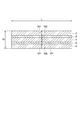
- FIG. 1 is a cross-sectional view in the lateral direction showing an example of an absorber.
- the absorber 50 shown in FIG. 1 has an absorption layer 10 and two core wrap sheets 20a and 20b.
- the core wrap sheets 20a and 20b are arranged on both sides of the absorption layer 10.
- the absorbent layer 10 is arranged inside the core wrap sheets 20a and 20b.
- the absorbent layer 10 is held in shape by being sandwiched between the two core wrap sheets 20a and 20b.
- the core wrap sheets 20a and 20b may be two sheets, one folded sheet, or one bag body.
- the absorption layer 10 includes a region ⁇ containing the first water-absorbent resin particles 10a having a swelling power of 5 N or more and a swelling power of 60 seconds or more of 7 N or more, and a first water-absorbent resin. It consists of a region ⁇ that does not contain the particles 10a.
- the region ⁇ may contain the second water-absorbent resin particles 10b having a swelling power of less than 5 N for 10 seconds or a swelling power of less than 7 N for 60 seconds. It does not have to contain the first and second water-absorbent resin particles).
- the region ⁇ in the absorption layer 10 may be, for example, a void.
- the thickness of the absorption layer 10 is not particularly limited, but may be, for example, 20 mm or less, 15 mm or less, 10 mm or less, 5 mm or less, 4 mm or less, or 3 mm or less in a dry state, and is 0.1 mm or more or 0.3 mm or less. It may be the above.
- the mass per unit area of the absorption layer 10 may be 1000 g / m 2 or less, 800 g / m 2 or less, 600 g / m 2 or less, or 100 g / m 2 or more.
- the absorption layer 10 is composed of a region ⁇ and a region ⁇ , and the thickness of both regions and / or the mass per unit area may be the same or different.
- the water-absorbent resin particles existing in the region ⁇ are the first water-absorbent resin particles having a swelling power of 5 N or more for 10 seconds and a swelling power of 7 N or more for 60 seconds.
- the water-absorbent resin particles present in the region ⁇ have a swelling power of less than 5 N for 10 seconds or a swelling power of less than 7 N for 60 seconds.
- the second water-absorbent resin particles are the first water-absorbent resin particles having a swelling power of 5 N or more for 10 seconds and a swelling power of 7 N or more for 60 seconds.
- the 10-second value of the swelling power and the 60-second value of the swelling power are measured by the swelling power test performed in the order of i), ii), iii), iv) and v) below.
- i) Prepare a cylinder with an inner diameter of 20 mm, which has openings at both ends and has a mesh mounted on one of the openings, with the cylinder standing vertically with the side on which the mesh is mounted facing down.
- 0.1 g of water-absorbent resin particles are uniformly sprayed on the mesh in the cylinder, and a cylindrical jig having a diameter of 19.5 mm is placed on the mesh.
- a glass filter having a thickness of 5 mm is placed in a horizontally installed petri dish, and the glass filter is impregnated with physiological saline to a position slightly below the upper surface thereof.
- An impermeable sheet is placed on the upper surface of a glass filter permeated with physiological saline, and a cylinder containing water-absorbent resin particles is erected vertically on the impermeable sheet with the mesh facing down.
- iv) Remove the impermeable sheet and start water absorption by the water-absorbent resin particles.
- the 10-second value of the swelling power may be 5N or more, 6N or more, 7N or more, 8N or more, 9N or more, 10N or more, or 11N or more, 20N or less, 18N. Hereinafter, it may be 16N or less, 14N or less, or 13N or less.
- the 10-second value of the swelling power may be 5N or more and 20N or less, 5N or more and 18N or less, 5N or more and 16N or less, or 5N or more and 14N or less, or 5N or more and 13N or less.
- the 60-second value of the swelling power may be 7N or more, 9N or more, 11N or more, 13N or more, or 14N or more, and 30N or less, 25N or less, 20N or less, 18N. It may be less than or equal to 16N or less.
- the 60-second value of the swelling power may be 7N or more and 30N or less, 7N or more and 25N or less, 7N or more and 20N or less, 7N or more and 18N or less, or 7N or more and 16N or less.
- the 10-second value of the swelling power may be less than 5N, 4N or less, and 0N or more.
- the 10-second value of the swelling power may be 0N or more and less than 5N, or 0N or more and 4N or less.
- the 60-second value of the swelling force may be less than 7N.
- the 60-second value of the swelling power may be 20 N or less, 16 N or less, 12 N or less, 8 N or less, or 5 N or less.
- the 60-second value of the swelling force may be 0N or more and less than 7N, and may be 0N or more and 20N or less.
- the 10-second value of the swelling force can be determined by, for example, changing the shape of the water-absorbent resin particles to adjust the specific surface area, performing surface treatment to make the surface of the water-absorbent resin hydrophilic, internal cross-linking and surface cross-linking. It can be controlled by adjusting the balance of the light and shade of the cross-linking density in one particle according to the above.
- the 60-second value of the swelling force can be controlled, for example, by adjusting the balance of the light and shade of the cross-linking density in one particle by the internal cross-linking and the surface cross-linking.
- the water absorption amount of the physiological saline of the first water-absorbent resin particles 10a may be, for example, 20 to 80 g / g, 30 to 70 g / g, or 40 to 65 g / g.
- the water absorption rate (Vortex method) of the first water-absorbent resin particles 10a may be, for example, 1 to 70 seconds, 2 to 50 seconds, 2 to 25 seconds, or 2 to 10 seconds.
- the water absorption amount of the physiological saline of the second water-absorbent resin particles 10b may be, for example, 20 to 80 g / g, 30 to 70 g / g, or 40 to 65 g / g.
- the water absorption rate (Vortex method) of the second water-absorbent resin particles 10b may be, for example, 2 to 70 seconds, 15 to 60 seconds, 25 seconds to 50 seconds, or 25 seconds to 40 seconds.
- the water absorption amount and the water absorption rate of the physiological saline can be measured by the method described in Examples described later.
- first water-absorbent resin particles or second water-absorbent resin particles is not particularly limited, and may be, for example, substantially spherical, crushed, or granular, and has these shapes. Particles in which primary particles are aggregated may be formed.
- the medium particle size of the water-absorbent resin particles may be 100 to 800 ⁇ m, 150 to 700 ⁇ m, 200 to 600 ⁇ m, or 250 to 500 ⁇ m.
- the medium particle size can be measured by the following method. From the top, JIS standard sieves have a mesh size of 600 ⁇ m, a mesh size of 500 ⁇ m, a mesh size of 425 ⁇ m, a mesh size of 300 ⁇ m, a mesh size of 250 ⁇ m, a mesh size of 180 ⁇ m, a mesh size of 150 ⁇ m, and a sieve. , Combine in the order of the saucer.
- the mass of the particles remaining on each sieve is calculated as a mass percentage with respect to the total amount to obtain the particle size distribution.
- the relationship between the mesh size of the sieve and the integrated value of the mass percentage of the particles remaining on the sieve is plotted on the logarithmic probability paper by integrating the particles on the sieve in order from the one having the largest particle size with respect to this particle size distribution. By connecting the plots on the probability paper with a straight line, the particle size corresponding to the cumulative mass percentage of 50% by mass is obtained as the medium particle size.
- the water-absorbent resin particles may include, for example, polymer particles formed by polymerization of a monomer containing an ethylenically unsaturated monomer. it can.
- the polymer particles may be water-absorbent particles containing a polymer contained as a monomer unit derived from an ethylenically unsaturated monomer.
- the ethylenically unsaturated monomer may be a water-soluble monomer, and examples thereof include (meth) acrylic acid and salts thereof, 2- (meth) acrylamide-2-methylpropanesulfonic acid and its salts.
- the amino group may be quaternized.
- the ethylenically unsaturated monomer may be used alone or in combination of two or more.
- Functional groups such as the carboxyl group and amino group of the above-mentioned monomers can function as functional groups capable of cross-linking in the surface cross-linking step described later.
- the ethylenically unsaturated monomer may be used alone or in combination of two or more.
- the proportion of the polymer containing the ethylenically unsaturated monomer as a monomer unit in the polymer particles is 50 to 100% by mass, 60 to 100% by mass, and 70 to 100% by mass based on the mass of the polymer particles. , Or 80 to 100% by mass.
- the polymer particles may be particles containing a (meth) acrylic acid-based polymer containing at least one of (meth) acrylic acid or (meth) acrylate as a monomer unit.
- the total ratio of the monomer units derived from (meth) acrylic acid or (meth) acrylate in the (meth) acrylic acid-based polymer may be 70 to 100% by mass based on the mass of the polymer. , 90-100% by mass.
- the water-absorbent resin particles (first water-absorbent resin particles or second water-absorbent resin particles) can be produced by a method including a step of polymerizing a monomer containing an ethylenically unsaturated monomer.
- the polymerization method include a reverse phase suspension polymerization method, an aqueous solution polymerization method, a bulk polymerization method, and a precipitation polymerization method. From the viewpoint of ensuring good water absorption characteristics of the obtained water-absorbent resin particles and facilitating control of the polymerization reaction, a reverse phase suspension polymerization method or an aqueous solution polymerization method may be applied.
- a reverse phase suspension polymerization method will be described as an example.
- the ethylenically unsaturated monomer is at least one selected from the group consisting of (meth) acrylic acid and salts thereof, acrylamide, methacrylamide, and N, N-dimethylacrylamide. It may contain a compound of the species.
- the ethylenically unsaturated monomer may contain (meth) acrylic acid and a salt thereof, and at least one compound selected from the group consisting of acrylamide.
- the ethylenically unsaturated monomer may contain at least one compound selected from the group consisting of (meth) acrylic acid and salts thereof.
- the ethylenically unsaturated monomer can be used in the polymerization reaction as an aqueous solution.
- concentration of the ethylenically unsaturated monomer in the aqueous solution containing the ethylenically unsaturated monomer (hereinafter, simply referred to as "monomeric aqueous solution”) is 20% by mass or more and the saturation concentration or less, 25 to 70% by mass, or 30. It may be up to 55% by mass.
- Examples of the water used in the aqueous solution include tap water, distilled water, ion-exchanged water and the like.
- a monomer other than the above-mentioned ethylenically unsaturated monomer may be used.
- Such a monomer can be used, for example, by mixing with an aqueous solution containing the above-mentioned ethylenically unsaturated monomer.
- the amount of the ethylenically unsaturated monomer used may be 70 to 100 mol% with respect to the total amount of the monomer.
- the ratio of (meth) acrylic acid and a salt thereof may be 70 to 100 mol% with respect to the total amount of the monomer.
- the acidic group may be neutralized with an alkaline neutralizer and then the monomer solution may be used in the polymerization reaction.
- the degree of neutralization of an ethylenically unsaturated monomer by an alkaline neutralizing agent increases the osmotic pressure of the obtained water-absorbent resin particles and further enhances the water absorption characteristics (water absorption amount, etc.). It may be 10-100 mol%, 50-90 mol%, or 60-80 mol% of the acidic group in the body.
- alkaline neutralizing agent examples include alkali metal salts such as sodium hydroxide, sodium carbonate, sodium hydrogen carbonate, potassium hydroxide and potassium carbonate; ammonia and the like.
- the alkaline neutralizer may be used alone or in combination of two or more.
- the alkaline neutralizer may be used in the form of an aqueous solution to simplify the neutralization operation. Neutralization of the acidic group of the ethylenically unsaturated monomer can be performed, for example, by dropping an aqueous solution of sodium hydroxide, potassium hydroxide or the like into the above-mentioned monomer aqueous solution and mixing them.
- an aqueous monomer solution is dispersed in a hydrocarbon dispersion medium in the presence of a surfactant, and an ethylenically unsaturated monomer is polymerized using a radical polymerization initiator or the like.
- a radical polymerization initiator a water-soluble radical polymerization initiator can be used.
- surfactant examples include nonionic surfactants, anionic surfactants and the like.
- nonionic surfactant sorbitan fatty acid ester and (poly) glycerin fatty acid ester (“(poly)” means both with and without the prefix of “poly”. The same shall apply hereinafter.
- Sucrose fatty acid ester polyoxyethylene sorbitan fatty acid ester, polyoxyethylene glycerin fatty acid ester, sorbitol fatty acid ester, polyoxyethylene sorbitol fatty acid ester, polyoxyethylene alkyl ether, polyoxyethylene alkyl phenyl ether, polyoxyethylene himashi
- oil polyoxyethylene hydrogenated castor oil, alkylallyl formaldehyde condensed polyoxyethylene ether, polyoxyethylene polyoxypropylene block copolymer, polyoxyethylene polyoxypropyl alkyl ether, polyethylene glycol fatty acid ester and the like.
- Anionic surfactants include fatty acid salts, alkylbenzene sulfonates, alkylmethyl taurates, polyoxyethylene alkylphenyl ether sulfates, polyoxyethylene alkyl ether sulfonates, and polyoxyethylene alkyl ether phosphates. , And the phosphate ester of polyoxyethylene alkyl allyl ether and the like.
- the surfactant may be used alone or in combination of two or more.
- the surfactant is a sorbitan fatty acid ester. It may contain at least one compound selected from the group consisting of polyglycerin fatty acid ester and sucrose fatty acid ester. From the viewpoint of easily improving the water absorption characteristics of the obtained water-absorbent resin particles, sorbitan fatty acid ester (for example, sorbitan monolaurate) and / or sucrose fatty acid ester (for example, sucrose stearic acid ester) are used as the surfactant. Good. These surfactants may be used alone or in combination of two or more.
- the amount of the surfactant may be 0.05 to 10 parts by mass, 0.08 to 5 parts by mass, or 0.1 to 3 parts by mass with respect to 100 parts by mass of the aqueous monomer solution.
- a polymer-based dispersant may be used in combination with the above-mentioned surfactant.
- the polymer dispersant include maleic anhydride-modified polyethylene, maleic anhydride-modified polypropylene, maleic anhydride-modified ethylene / propylene copolymer, maleic anhydride-modified EPDM (ethylene / propylene / diene / terpolymer), and maleic anhydride.
- the polymer-based dispersant may be used alone or in combination of two or more.
- the polymer-based dispersant includes maleic anhydride-modified polyethylene, maleic anhydride-modified polypropylene, maleic anhydride-modified ethylene / propylene copolymer, and maleic anhydride / ethylene copolymer.
- Maleic anhydride / propylene copolymer, maleic anhydride / ethylene / propylene copolymer, polyethylene, polypropylene, ethylene / propylene copolymer, oxidized polyethylene, oxidized polypropylene, and oxidized ethylene / propylene copolymer It may be at least one selected from the group consisting of.
- the amount of the polymer-based dispersant may be 0.05 to 10 parts by mass, 0.08 to 5 parts by mass, or 0.1 to 3 parts by mass with respect to 100 parts by mass of the aqueous monomer solution.
- the hydrocarbon dispersion medium may contain at least one compound selected from the group consisting of chain aliphatic hydrocarbons having 6 to 8 carbon atoms and alicyclic hydrocarbons having 6 to 8 carbon atoms.
- Hydrocarbon dispersion media include chain aliphatic hydrocarbons such as n-hexane, n-heptane, 2-methylhexane, 3-methylhexane, 2,3-dimethylpentane, 3-ethylpentane, and n-octane; cyclohexane.
- the hydrocarbon dispersion medium may be used alone or in combination of two or more.
- the hydrocarbon dispersion medium may contain at least one selected from the group consisting of n-heptane and cyclohexane.
- the mixture of the above-mentioned hydrocarbon dispersion medium for example, commercially available ExxonHeptane (manufactured by ExxonMobil: containing 75 to 85% of n-heptane and isomeric hydrocarbons) is used. You may.
- the amount of the hydrocarbon dispersion medium is 30 to 1000 parts by mass, 40 to 500 parts by mass, or 50 parts by mass with respect to 100 parts by mass of the monomer aqueous solution from the viewpoint of appropriately removing the heat of polymerization and easily controlling the polymerization temperature. It may be up to 300 parts by mass. When the amount of the hydrocarbon dispersion medium is 30 parts by mass or more, the polymerization temperature tends to be easily controlled. When the amount of the hydrocarbon dispersion medium is 1000 parts by mass or less, the productivity of polymerization tends to be improved, which is economical.
- the radical polymerization initiator may be water-soluble.
- water-soluble radical polymerization initiators include persulfates such as potassium persulfate, ammonium persulfate, and sodium persulfate; methyl ethyl ketone peroxide, methyl isobutyl ketone peroxide, di-t-butyl peroxide, and t-butyl cumylper.
- Peroxides such as oxides, t-butylperoxyacetate, t-butylperoxyisobutyrate, t-butylperoxypivalate, hydrogen peroxide; 2,2'-azobis (2-amidinopropane) dihydrochloride , 2,2'-azobis [2- (N-phenylamidino) propane] dihydrochloride, 2,2'-azobis [2- (N-allylamidino) propane] dihydrochloride, 2,2'-azobis [ 2- (2-imidazolin-2-yl) propane] 2 hydrochloride, 2,2'-azobis ⁇ 2- [1- (2-hydroxyethyl) -2-imidazolin-2-yl] propane ⁇ 2 hydrochloride, 2,2'-azobis ⁇ 2-methyl-N- [1,1-bis (hydroxymethyl) -2-hydroxyethyl] propionamide ⁇ , 2,2'-azobis [2-methyl-N- (2-hydroxy) Ethyl) -propion
- the radical polymerization initiator may be used alone or in combination of two or more. Radical polymerization initiators are potassium persulfate, ammonium persulfate, sodium persulfate, 2,2'-azobis (2-amidinopropane) dihydrochloride, 2,2'-azobis [2- (2-imidazolin-2-yl). ) Propane] 2 hydrochloride and 2,2'-azobis ⁇ 2- [1- (2-hydroxyethyl) -2-imidazolin-2-yl] propane ⁇ 2 hydrochloride, at least one selected from the group. There may be.
- the amount of the radical polymerization initiator may be 0.00005 to 0.01 mol per 1 mol of the ethylenically unsaturated monomer.
- the amount of the radical polymerization initiator used is 0.00005 mol or more, the polymerization reaction does not require a long time and is efficient.
- the amount of the radical polymerization initiator is 0.01 mol or less, it is easy to suppress the occurrence of a rapid polymerization reaction.
- the exemplified radical polymerization initiator can also be used as a redox polymerization initiator in combination with a reducing agent such as sodium sulfite, sodium hydrogen sulfite, ferrous sulfate, and L-ascorbic acid.
- a reducing agent such as sodium sulfite, sodium hydrogen sulfite, ferrous sulfate, and L-ascorbic acid.
- the aqueous monomer solution may contain a chain transfer agent.
- chain transfer agent include hypophosphates, thiols, thiolic acids, secondary alcohols, amines and the like.
- the monomer aqueous solution used for polymerization may contain a thickener in order to control the particle size of the water-absorbent resin particles.
- a thickener examples include hydroxyethyl cellulose, hydroxypropyl cellulose, methyl cellulose, carboxymethyl cellulose, polyacrylic acid, polyethylene glycol, polyacrylamide, polyethyleneimine, dextrin, sodium alginate, polyvinyl alcohol, polyvinylpyrrolidone, polyethylene oxide and the like. If the stirring speed at the time of polymerization is the same, the higher the viscosity of the aqueous monomer solution, the larger the medium particle size of the obtained particles tends to be.
- Cross-linking by self-cross-linking may occur during polymerization, but cross-linking may be further performed by using an internal cross-linking agent.
- an internal cross-linking agent When an internal cross-linking agent is used, it is easy to control the water absorption characteristics of the water-absorbent resin particles.
- the internal cross-linking agent is usually added to the reaction solution during the polymerization reaction.
- the internal cross-linking agent examples include di or tri (meth) acrylic acid esters of polyols such as ethylene glycol, propylene glycol, trimethylolpropane, glycerin, polyoxyethylene glycol, polyoxypropylene glycol, and polyglycerin; Unsaturated polyesters obtained by reacting polyols with unsaturated acids (maleic acid, fumaric acid, etc.); bis (meth) acrylamides such as N, N'-methylenebis (meth) acrylamide; polyepoxides and (meth) Di or tri (meth) acrylic acid esters obtained by reacting with acrylic acid; di (meth) obtained by reacting polyisocyanate (tolylene diisocyanate, hexamethylene diisocyanate, etc.) with hydroxyethyl (meth) acrylate.
- polyols such as ethylene glycol, propylene glycol, trimethylolpropane, glycerin, polyoxyethylene glycol,
- Acrylic acid carbamil esters compounds having two or more polymerizable unsaturated groups such as allylated starch, allylated cellulose, diallyl phthalate, N, N', N "-triallyl isocyanurate, divinylbenzene; Poly such as (poly) ethylene glycol diglycidyl ether, (poly) propylene glycol diglycidyl ether, (poly) glycerin diglycidyl ether, (poly) glycerin triglycidyl ether, (poly) propylene glycol polyglycidyl ether, polyglycerol polyglycidyl ether, etc.
- Poly such as (poly) ethylene glycol diglycidyl ether, (poly) propylene glycol diglycidyl ether, (poly) glycerin diglycidyl ether, (poly) glycerin triglycidyl ether, (poly) propylene
- Glyceridyl compound such as epichlorohydrin, epibromhydrin, ⁇ -methylepichlorohydrin; 2 reactive functional groups such as isocyanate compound (2,4-tolylene diisocyanate, hexamethylene diisocyanate, etc.) Examples thereof include compounds having more than one.
- the internal cross-linking agent may be used alone or in combination of two or more.
- the internal cross-linking agent may be a polyglycidyl compound or diglycidyl. It may be an ether compound.
- the internal cross-linking agent comprises at least one selected from the group consisting of (poly) ethylene glycol diglycidyl ether, (poly) propylene glycol diglycidyl ether, and (poly) glycerin diglycidyl ether. It may be.
- the amount of the internal cross-linking agent is not ethylenically from the viewpoint that the water-soluble property is suppressed by appropriately cross-linking the polymer obtained by the polymerization of the above-mentioned monomer aqueous solution, and a sufficient water absorption amount can be easily obtained. It may be 0 mmol or more, 0.01 mmol or more, 0.015 mmol or more, 0.020 mmol or more, or 0.1 mol or less, per 1 mol of saturated monomer.
- Reversed phase suspension polymerization can be carried out in an aqueous system in oil by heating with stirring in a state where the phases are mixed.
- a monomer aqueous solution containing an ethylenically unsaturated monomer is used as a hydrocarbon dispersion medium in the presence of a surfactant (and, if necessary, a polymer-based dispersant). Disperse in.
- the timing of adding the surfactant, the polymer-based dispersant, or the like may be either before or after the addition of the aqueous monomer solution, as long as it is before the start of the polymerization reaction.
- a surfactant is added after dispersing the monomer aqueous solution in the hydrocarbon dispersion medium in which the polymer-based dispersant is dispersed.
- the polymer may be further dispersed and then polymerized.
- Reverse phase suspension polymerization can be carried out in one stage or in multiple stages of two or more stages. Reversed phase suspension polymerization may be carried out in two or three stages from the viewpoint of increasing productivity.
- an ethylenically unsaturated monomer is added to the reaction mixture obtained in the first step polymerization reaction after the first step reverse phase suspension polymerization is carried out. It may be added and mixed, and the reverse phase suspension polymerization of the second and subsequent steps may be carried out in the same manner as in the first step.
- the above-mentioned radical polymerization initiator is used in the reverse phase suspension polymerization in each stage of the second and subsequent stages.
- the ethylenically unsaturated monomer to be added Based on the amount of the ethylenically unsaturated monomer to be added, it may be added within the range of the molar ratio of each component to the above-mentioned ethylenically unsaturated monomer to carry out reverse phase suspension polymerization.
- an internal cross-linking agent In the reverse phase suspension polymerization in each stage after the second stage, an internal cross-linking agent may be used if necessary.
- an internal cross-linking agent When an internal cross-linking agent is used, it is added within the range of the molar ratio of each component to the above-mentioned ethylenically unsaturated monomer based on the amount of the ethylenically unsaturated monomer provided in each stage, and the suspension is reversed. Muddy polymerization may be carried out.
- the temperature of the polymerization reaction varies depending on the radical polymerization initiator used, but by rapidly advancing the polymerization and shortening the polymerization time, the efficiency is improved and the heat of polymerization is easily removed to carry out the reaction smoothly. From the viewpoint, it may be 20 to 150 ° C. or 40 to 120 ° C.
- the reaction time is usually 0.5-4 hours.
- the completion of the polymerization reaction can be confirmed, for example, by stopping the temperature rise in the reaction system. As a result, the polymer of the ethylenically unsaturated monomer is usually obtained in the state of a hydrogel-like polymer.
- cross-linking may be performed after polymerization by adding a cross-linking agent to the obtained hydrogel polymer and heating it.
- a cross-linking agent to the obtained hydrogel polymer and heating it.
- cross-linking agent for performing post-polymerization cross-linking examples include polyols such as ethylene glycol, propylene glycol, 1,4-butanediol, trimethylolpropane, glycerin, polyoxyethylene glycol, polyoxypropylene glycol, and polyglycerin; Compounds having two or more epoxy groups such as (poly) ethylene glycol diglycidyl ether, (poly) propylene glycol diglycidyl ether, and (poly) glycerin diglycidyl ether; epichlorohydrin, epibromhydrin, ⁇ -methylepicrolhydrin and the like.
- polyols such as ethylene glycol, propylene glycol, 1,4-butanediol, trimethylolpropane
- glycerin polyoxyethylene glycol, polyoxypropylene glycol, and polyglycerin
- Compounds having two or more epoxy groups such as (poly) ethylene glyco
- Haloepoxy compounds compounds having two or more isocyanate groups such as 2,4-tolylene diisocyanate and hexamethylene diisocyanate; oxazoline compounds such as 1,2-ethylene bisoxazoline; carbonate compounds such as ethylene carbonate; bis [N , N-di ( ⁇ -hydroxyethyl)] hydroxyalkylamide compounds such as adipamide can be mentioned.
- Cross-linking agents for post-polymerization cross-linking are (poly) ethylene glycol diglycidyl ether, (poly) glycerin diglycidyl ether, (poly) glycerin triglycidyl ether, (poly) propylene glycol polyglycidyl ether, and polyglycerol polyglycidyl ether. It may be a polyglycidyl compound such as. These cross-linking agents may be used alone or in combination of two or more.
- the amount of the cross-linking agent used for post-polymerization cross-linking is 1 mol of the water-soluble ethylenically unsaturated monomer from the viewpoint of appropriately cross-linking the obtained hydrogel-like polymer to exhibit suitable water absorption characteristics. It may be 0 to 0.03 mol, 0 to 0.01 mol, or 0.00001 to 0.005 mol.
- the cross-linking agent for post-polymerization cross-linking is added to the reaction solution after the polymerization reaction of the ethylenically unsaturated monomer.
- a cross-linking agent for post-polymerization cross-linking may be added after the multi-stage polymerization.
- the cross-linking agent for post-polymerization cross-linking is , From the viewpoint of water content (described later), it may be added in the region of [water content immediately after polymerization ⁇ 3% by mass].
- drying to remove water gives polymer particles containing a polymer of ethylenically unsaturated monomers.
- the drying method include (a) a method of removing water by azeotropic distillation in a state where the hydrogel polymer is dispersed in a hydrocarbon dispersion medium, and (b) a method of taking out the hydrogel polymer by decantation and reducing the pressure. Examples thereof include a method of drying, and (c) a method of filtering the hydrogel polymer by a filter and drying under reduced pressure.
- the particle size of the water-absorbent resin particles can be adjusted by adjusting the rotation speed of the stirrer during the polymerization reaction, or by adding a flocculant into the system after the polymerization reaction or in the early stage of drying. By adding a flocculant, the particle size of the obtained water-absorbent resin particles can be increased.
- an inorganic flocculant can be used as the flocculant.
- the inorganic flocculant for example, powdered inorganic flocculant
- the aggregating agent may be at least one selected from the group consisting of silica (for example, amorphous silica), aluminum oxide, talc and kaolin.
- a coagulant is previously dispersed in a hydrocarbon dispersion medium of the same type as that used in the polymerization or water, and then this is placed in a hydrocarbon dispersion medium containing a hydrogel polymer under stirring. May be mixed with.
- the amount of the flocculant is 0.001 to 1 part by mass, 0.005 to 0.5 part by mass, or 0.01 to 0.2 with respect to 100 parts by mass of the ethylenically unsaturated monomer used for the polymerization. It may be a mass part. When the amount of the flocculant is within these ranges, it is easy to obtain water-absorbent resin particles having a desired particle size distribution.
- the polymerization reaction can be carried out using various stirrers having stirring blades.
- a flat plate blade a lattice blade, a paddle blade, a propeller blade, an anchor blade, a turbine blade, a Faudler blade, a ribbon blade, a full zone blade, a max blend blade and the like can be used.
- the flat plate blade has a shaft (stirring shaft) and a flat plate portion (stirring portion) arranged around the shaft. Further, the flat plate portion may have a slit or the like.
- the cross-linking (surface cross-linking) of the surface portion of the hydrogel polymer may be carried out using a cross-linking agent in any of the drying steps and subsequent steps.
- a cross-linking agent By performing surface cross-linking, it is easy to control the water absorption characteristics of the water-absorbent resin particles.
- the water content of the surface-crosslinked hydrogel polymer may be 5 to 50% by mass, 10 to 40% by mass, or 15 to 35% by mass.
- the amount of water in the hydrogel polymer calculated by adding the amount of water used according to.
- Ws The amount of solid content calculated from the amount of materials such as ethylenically unsaturated monomers, cross-linking agents, and initiators that make up the hydrogel polymer.
- surface cross-linking agents include, for example, polyols such as ethylene glycol, propylene glycol, 1,4-butanediol, trimethylolpropane, glycerin, polyoxyethylene glycol, polyoxypropylene glycol, and polyglycerin; (poly) ethylene.
- Polyglycidyl compounds such as glycol diglycidyl ether, (poly) glycerin diglycidyl ether, (poly) glycerin triglycidyl ether, trimethylpropan triglycidyl ether (poly) propylene glycol polyglycidyl ether, (poly) glycerol polyglycidyl ether; Haloepoxy compounds such as chlorohydrin, epibromhydrin, ⁇ -methylepichlorohydrin; isocyanate compounds such as 2,4-tolylene diisocyanate, hexamethylene diisocyanate; 3-methyl-3-oxetane methanol, 3-ethyl- Oxetane compounds such as 3-oxetane methanol, 3-butyl-3-oxetane methanol, 3-methyl-3-oxetaneethanol, 3-ethyl-3-oxetaneethanol, 3-butyl-3-o
- the surface cross-linking agent may be used alone or in combination of two or more.
- the surface cross-linking agent may be a polyglycidyl compound, and may be (poly) ethylene glycol diglycidyl ether, (poly) glycerin diglycidyl ether, (poly) glycerin triglycidyl ether, (poly) propylene glycol polyglycidyl ether, and poly. It may be at least one selected from the group consisting of glycerol polyglycidyl ether.
- the amount of the surface cross-linking agent used is 0.01 to 20 mmol, 0.05 to 10 mmol, based on 1 mol of the ethylenically unsaturated monomer used for the polymerization, from the viewpoint that suitable water absorption characteristics can be easily obtained. It may be 0.1-5 mmol, 0.15-3 mmol, or 0.2-1 mmol.
- the surface portion of the hydrogel polymer is treated (surface modification) with a surface modifier in either the drying step (moisture removal step) or a subsequent step. May be good.
- the surface modification may be carried out, for example, before, during or after the surface cross-linking step.
- Surface modification may be carried out after surface cross-linking.
- the surface modifier may be, for example, a surfactant such as a nonionic surfactant, an anionic surfactant, a cationic surfactant, or an amphoteric surfactant.
- a surfactant such as a nonionic surfactant, an anionic surfactant, a cationic surfactant, or an amphoteric surfactant.
- the HLB value of the nonionic surfactant used as the surface modifier may be, for example, 3 to 12, or 6 to 10.
- the nonionic surfactant include sorbitan fatty acid esters such as sorbitan monolaurate. The HLB value is measured by the Griffin method.
- the amount of the surface modifier is 0.01 to 0.50 parts by mass, 0.02 to 0.40 parts by mass, or 0.04 with respect to 100 parts by mass of the ethylenically unsaturated monomer used for the polymerization. It may be ⁇ 0.30 parts by mass.
- water and a hydrocarbon dispersion medium can be distilled off from the hydrogel polymer to obtain polymer particles which are dry products. it can.
- the water-absorbent resin particles may be composed of only polymer particles, but may further contain various additional components selected from, for example, a gel stabilizer, a metal chelating agent, a fluidity improver (lubricant), and the like. Can be done. Additional components may be placed inside the polymer particles, on the surface of the polymer particles, or both. The additional component may be a fluidity improver (lubricant).
- the fluidity improver may contain inorganic particles. Examples of the inorganic particles include silica particles such as amorphous silica.
- the water-absorbent resin particles may contain a plurality of inorganic particles arranged on the surface of the polymer particles. For example, by mixing the polymer particles and the inorganic particles, the inorganic particles can be arranged on the surface of the polymer particles.
- the inorganic particles may be silica particles such as amorphous silica.
- the ratio of the amount of the inorganic particles to the mass of the polymer particles is 0.2% by mass or more, 0.5% by mass or more, 1 It may be 0.0% by mass or more, 1.5% by mass or more, 5.0% by mass or less, or 3.5% by mass or less.
- the inorganic particles here usually have a minute size as compared with the size of the polymer particles.
- the average particle size of the inorganic particles may be 0.1 to 50 ⁇ m, 0.5 to 30 ⁇ m, or 1 to 20 ⁇ m.
- the average particle size here can be a value measured by a dynamic light scattering method or a laser diffraction / scattering method.
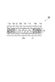
- FIG. 2 is a top view of the strip-shaped absorption layer according to the embodiment.
- the absorption layer 10A shown in FIG. 2 includes a region ⁇ extending in the longitudinal direction of the absorption layer in the center of the absorption layer, and portions extending in the longitudinal direction of the absorption layer on both sides of the region ⁇ in the lateral direction. Includes region ⁇ and.
- FIG. 3 is a top view of the strip-shaped absorbing layer according to another embodiment.
- the region ⁇ extends in the longitudinal direction of the absorption layer on both sides of the region ⁇ in the lateral direction, and the region ⁇ extends in the longitudinal direction of the region ⁇ in the lateral direction of the absorption layer. Includes parts that extend to.
- the region ⁇ has a shape surrounding the region ⁇ .
- the region ⁇ extends from the center of the main surface of the absorption layer to both sides in the longitudinal direction by 2/5 L or more and absorbs. It may be provided in a portion extending 1/8 W or more on both sides in the lateral direction from the center of the main surface of the layer.
- the longitudinal length of the region ⁇ may be the same as the longitudinal length of the absorption layer 10.
- the region ⁇ may be provided along the longitudinal direction of the absorption layer on both sides of the region ⁇ in the lateral direction, and may include a portion extending 1/8 W or more in the lateral direction of the absorption layer.
- the longitudinal direction of the absorbent layer is the direction extending in the anteroposterior direction of the user's crotch when worn by the user, and the lateral direction of the absorbent layer is on the same plane as the main surface of the absorbent layer.
- the direction is orthogonal to the longitudinal direction.
- the liquid to be absorbed first invades the region ⁇ extending along the longitudinal direction in the center of the absorption layer.
- the first absorbent resin particles contained in the region ⁇ swell.
- the liquid was absorbed by arranging the first water-absorbent resin particles having a swelling force of 10 seconds value and 60 seconds value or more, which are indicators reflecting the rapid swelling and the large swelling, in the region ⁇ .
- the phenomenon that the edge of the absorbent layer becomes higher than that of the central part (pocket formation) is likely to occur, and as a result, lateral leakage from the crotch area of the absorbent article (from the region ⁇ ) when worn by the user. It is considered that the leakage of the absorber generated through the region ⁇ from the lateral side can be blocked, and as a result, the liquid leakage is suppressed.
- the factors that suppress liquid leakage are not limited to the above factors.
- the length W of the absorption layer 10 in the lateral direction may be, for example, 5 cm or more, 6 cm or more, or 7 cm or more, and is 18 cm or less, 16 cm or less, 14 cm or less, 12 cm or less, 10 cm. It may be less than or equal to 9 cm or less.
- the length L in the longitudinal direction of the absorption layer may be, for example, 20 cm or more, 22 cm or more, 24 cm or more, or 26 cm or more, and may be 60 cm or less, 50 cm or less, 40 cm or less, 38 cm or less, 36 cm or less, 34 cm or less, 32 cm or less. , Or 30 cm or less.
- the area of the region ⁇ may be 10% or more and 90% or less, 15% or more and 85% or less, and 20% or more and 80% with respect to the area of the main surface of the absorption layer. It may be% or less, and may be 25% or more and 75% or less.
- the area of the region ⁇ may be 10% or more and 90% or less, 15% or more and 85% or less, and 20% or more and 80% with respect to the area of the main surface of the absorption layer. It may be% or less, and may be 25% or more and 75% or less.
- the length W1 of the region ⁇ (the length between the long side of the region ⁇ and the long side of the opposite region ⁇ ) in the lateral direction of the absorption layer is, for example, 0.5 cm or more and 1 cm or more. It may be 5 cm or more, or 2 cm or more, and may be 5.0 cm or less, 4.0 cm or less, 3.5 cm or less, 3.0 cm or less, or 2.5 cm or less.
- the ratio (W1 / W) of the length W1 of the region ⁇ in the lateral direction of the absorbing layer to the length W in the lateral direction of the absorbing layer may be, for example, 1/10 to 3/10.
- the length W2 of the region ⁇ in the lateral direction of the absorption layer may be, for example, 0.5 cm or more, 1 cm or more, 1.5 cm or more, or 2 cm or more, and 5.0 cm or less, 4.0 cm or less, 3 It may be 5.5 cm or less, 3.0 cm or less, or 2.5 cm or less.
- the length W2 (W2 / W) of the region ⁇ in the lateral direction of the absorbing layer with respect to the length W in the lateral direction of the absorbing layer is, for example, 1/10 to 7/10 or 1/5 to 3/5. It may be there.
- the length L1 of the region ⁇ (the length between the short side of the region ⁇ and the short side of the opposite region ⁇ ) in the longitudinal direction of the absorption layer is, for example, 1 cm or more, 1.5 cm or more, and 2 cm. It may be more than or equal to or 3 cm or more, and may be 5.0 cm or less, 4.5 cm or less, 4.0 cm or less, or 2.5 cm or less.
- the ratio (L1 / L) of the length L1 of the region ⁇ in the longitudinal direction of the absorption layer to the length L in the longitudinal direction of the absorption layer is, for example, 2/28 to 5/28 or 3/28 to 4/28. May be.
- the length L2 of the region ⁇ in the longitudinal direction of the absorption layer may be, for example, 18 cm or more, or 20 cm or more, and may be 26 cm or less, 25 cm or less, or 23 cm or less.
- the ratio (L2 / L) of the length L2 of the region ⁇ in the longitudinal direction of the absorption layer to the length L in the longitudinal direction of the absorption layer may be, for example, 18/28 to 25/28.
- the absorption layer 10 may or may not have the fiber layers 11a and 11b containing the fibrous material. That is, the absorption layer 10 may contain fibrous substances and may not substantially contain fibrous substances.
- the content of the fibrous material when substantially free of the fibrous material may be 10% by mass or less, 5% by mass or less, or 0% by mass, based on the mass of the absorbing layer. ..
- the fibrous material constituting the fiber layers 11a and 11b can be, for example, a cellulosic fiber, a synthetic fiber, or a combination thereof.
- cellulosic fibers include crushed wood pulp, cotton, cotton linters, rayon and cellulosic acetate.
- synthetic fibers include polyamide fibers, polyester fibers, and polyolefin fibers.
- the fibrous material may be hydrophilic fibers (for example, pulp).
- the absorption layer 10 may further contain inorganic particles (for example, amorphous silica), a deodorant, an antibacterial agent, a fragrance, and the like.
- inorganic particles for example, amorphous silica
- the absorption layer 10 may contain inorganic particles in addition to the inorganic particles in the water-absorbent resin particles.
- the content of the water-absorbent resin particles in the absorption layer may be 70 to 100% by mass, 80 to 100% by mass, or 90 to 100% by mass based on the mass of the absorption layer 10.
- the core wrap sheets 20a and 20b in the absorber 50 may be, for example, a non-woven fabric.
- the two core wrap sheets 20a and 20b can be the same or different non-woven fabrics.
- the non-woven fabric may be a non-woven fabric composed of short fibers (that is, staples) (short-fiber non-woven fabric) or a non-woven fabric composed of long fibers (that is, filaments) (long-fiber non-woven fabric). Staples are not limited to this, but generally may have a fiber length of several hundred mm or less.
- the core wrap sheets 20a and 20b are laminated including a thermal bond non-woven fabric, an air-through non-woven fabric, a resin bond non-woven fabric, a spunbond non-woven fabric, a melt blow non-woven fabric, an air-laid non-woven fabric, a spunlace non-woven fabric, a point bond non-woven fabric, or two or more kinds of non-woven fabrics selected from these. It can be a body.
- the non-woven fabric used as the core wrap sheets 20a and 20b can be a non-woven fabric formed of synthetic fibers, natural fibers, or a combination thereof.
- synthetic fibers include polyolefins such as polyethylene (PE) and polypropylene (PP), polyesters such as polyethylene terephthalate (PET), polytrimethylene terephthalate (PTT) and polyethylene naphthalate (PEN), polyamides such as nylon, and Examples thereof include fibers containing a synthetic resin selected from rayon.
- Examples of natural fibers include fibers containing cotton, silk, hemp, or pulp (cellulose).
- the fibers forming the non-woven fabric may be polyolefin fibers, polyester fibers or a combination thereof.
- the core wrap sheets 20a and 20b may be tissue paper.
- the core wrap sheets 20a and 20b may have a main surface wider than the main surface of the absorption layer 10. That is, the outer edges of the core wrap sheets 20a and 20b may extend around the absorption layer 10. The core wrap sheets 20a and 20b may be adhered to each other at the outer edge portion extending around the absorption layer 10.
- the absorber 50 may further have an adhesive 21 interposed between the core wrap sheets 20a and 20b and the absorbent layer 10.
- FIG. 4 is a plan view showing an example of an adhesive pattern formed on the core wrap sheet.
- the adhesive 21 shown in FIG. 4 forms a pattern composed of a plurality of linear portions arranged at intervals on the core wrap sheet 20a.
- the pattern of the adhesive 21 is not limited to this.
- An adhesive may be interposed only between one of the core wrap sheets 20a and 20b and the absorbent layer 10.
- the adhesive 21 is not particularly limited, and may be, for example, a hot melt adhesive.
- the absorber 50 is formed by sandwiching, for example, an absorbent layer having a region ⁇ containing the first water-absorbent resin particles and a region ⁇ containing the second water-absorbent resin particles between the core wrap sheets 20a and 20b. It can be obtained by a method of pressurizing the structure while heating it if necessary. If necessary, the adhesive 21 is arranged between the core wrap sheets 20a and 20b and the absorbent layer.
- the absorber 50 is used, for example, to produce various absorbent articles.
- absorbent articles include diapers (eg paper diapers), toilet training pants, incontinence pads, sanitary materials (sanitary napkins, tampons, etc.), sweat pads, pet sheets, toilet components, and animal waste treatment materials. Can be mentioned.
- FIG. 5 is a cross-sectional view showing an example of an absorbent article.
- the absorbent article 100 shown in FIG. 5 includes an absorbent body 50, a liquid permeable sheet 30, and a liquid permeable sheet 40.
- the absorbent body 50 is sandwiched between the liquid permeable sheet 30 and the liquid permeable sheet 40.
- the liquid permeable sheet 30 is arranged at the position of the outermost layer on the side where the liquid to be absorbed enters.
- the liquid permeable sheet 30 is arranged on the outside of the core wrap sheet 20b in contact with the core wrap sheet 20b.
- the liquid permeable sheet 40 is arranged at the position of the outermost layer on the side opposite to the liquid permeable sheet 30 in the absorbent article 100.
- the liquid impermeable sheet 40 is arranged on the outside of the core wrap sheet 20a in a state of being in contact with the core wrap sheet 20a.
- the liquid permeable sheet 30 and the liquid permeable sheet 40 have a main surface wider than the main surface of the absorber 50, and the outer edges of the liquid permeable sheet 30 and the liquid permeable sheet 40 are an absorbent layer.
- the magnitude relationship between the absorbent layer 10, the core wrap sheets 20a and 20b, the liquid permeable sheet 30, and the liquid permeable sheet 40 is not particularly limited, and is appropriately adjusted according to the use of the absorbent article and the like. ..
- the liquid permeable sheet 30 may be a non-woven fabric.
- the non-woven fabric used as the liquid permeable sheet 30 may have appropriate hydrophilicity from the viewpoint of the liquid absorption performance of the absorbent article. From this point of view, the liquid permeable sheet 30 is obtained from the pulp and paper test method No. 1 by the Paper and Pulp Technology Association. A non-woven fabric having a hydrophilicity of 5 to 200 measured according to the measuring method of 68 (2000) may be used. The hydrophilicity of the non-woven fabric may be 10 to 150. Pulp and paper test method No. For details of 68, for example, WO2011 / 086843 can be referred to.
- the non-woven fabric having hydrophilicity may be formed of fibers showing appropriate hydrophilicity such as rayon fiber, or obtained by hydrophilizing a hydrophobic chemical fiber such as polyolefin fiber or polyester fiber. It may be formed of rayon fibers.
- Examples of a method for obtaining a non-woven fabric containing hydrophobic chemical fibers that have been hydrophilized include a method for obtaining a non-woven fabric by a spunbond method using a mixture of hydrophobic chemical fibers and a hydrophilic agent, and hydrophobic chemistry.
- Hydrophilic agents include anionic surfactants such as aliphatic sulfonates and higher alcohol sulfates, cationic surfactants such as quaternary ammonium salts, polyethylene glycol fatty acid esters, polyglycerin fatty acid esters, and sorbitan fatty acids.
- Nonionic surfactants such as esters, silicone-based surfactants such as polyoxyalkylene-modified silicones, and stain-releasing agents made of polyester-based, polyamide-based, acrylic-based, and urethane-based resins are used.
- the amount of texture (mass per unit area) of the non-woven fabric used as the liquid permeable sheet 30 is from the viewpoint of imparting good liquid permeability, flexibility, strength and cushioning property to the absorbent article, and the liquid of the absorbent article. From the viewpoint of increasing the permeation rate, it may be 5 to 200 g / m 2 , 8 to 150 g / m 2 , or 10 to 100 g / m 2 .
- the thickness of the liquid permeable sheet 30 may be 20 to 1400 ⁇ m, 50 to 1200 ⁇ m, or 80 to 1000 ⁇ m.
- the liquid impermeable sheet 40 prevents the liquid absorbed by the absorbing layer 10 from leaking to the outside from the liquid impermeable sheet 40 side.
- the liquid impermeable sheet 40 may be a resin sheet or a non-woven fabric.
- the resin sheet may be a sheet made of a synthetic resin such as polyethylene, polypropylene, or polyvinyl chloride.
- the non-woven fabric may be a spunbond / meltblow / spunbond (SMS) non-woven fabric in which a water-resistant melt-blow non-woven fabric is sandwiched between high-strength spunbond non-woven fabrics.
- SMS spunbond / meltblow / spunbond
- the liquid impermeable sheet 40 may be a composite sheet of a resin sheet and a non-woven fabric (for example, a spunbonded non-woven fabric or a spunlaced non-woven fabric).
- the liquid impermeable sheet 40 may have breathability from the viewpoint that stuffiness at the time of wearing is reduced and discomfort given to the wearer can be reduced.
- a sheet of low density polyethylene (LDPE) resin can be used as the liquid impermeable sheet 40 having breathability.
- the basis weight (mass per unit area) of the liquid impermeable sheet 40 may be 10 to 50 g / m 2.
- the absorbent article 100 can be manufactured, for example, by a method including arranging the absorbent body 50 between the liquid permeable sheet 30 and the liquid permeable sheet 40. A laminate in which the liquid permeable sheet 40, the absorber 50, and the liquid permeable sheet 30 are laminated in this order is pressurized as necessary. Alternatively, the liquid permeable sheet 30, the core wrap sheet 20b, the water-absorbent resin particles 10a, or the mixture containing the water-absorbent resin particles 10a and the fibrous material, and the core wrap sheet 20a and the liquid impermeable sheet 40 are used. The absorbent article 100 can also be obtained by arranging in this order and pressurizing the formed structure while heating if necessary.
- n-heptane as a hydrocarbon dispersion medium
- sorbitan monolaurate Naonion LP-20R, HLB value: 8.6, manufactured by NOF CORPORATION
- the mixture was obtained by addition.
- the sorbitan monolaurate was dissolved in n-heptane by heating the mixture to 50 ° C. while stirring at a stirring speed of 300 rpm, and then the mixture was cooled to 40 ° C.
- the inside of the system was sufficiently replaced with nitrogen. Then, the flask was immersed in a water bath at 70 ° C. and held for 60 minutes to complete the polymerization while stirring at a rotation speed of 700 rpm of the stirrer to obtain a hydrogel polymer.
- amorphous silica (Oriental Silicas Corporation, oriental silicas corporation, etc.) was added to the polymer solution containing the produced hydrogel polymer, n-heptane and a surfactant as a powdery inorganic flocculant.
- the flask containing the reaction solution was immersed in an oil bath at 125 ° C., and 98.0 g of water was extracted from the system while refluxing n-heptane by azeotropic distillation of n-heptane and water. Then, 4.14 g (ethylene glycol diglycidyl ether: 0.475 mmol) of 2% by mass of an ethylene glycol diglycidyl ether aqueous solution was added as a surface cross-linking agent, and the mixture was maintained at an internal temperature of 83 ⁇ 2 ° C. for 2 hours.
- ethylene glycol diglycidyl ether 0.475 mmol
- sorbitan monolaurate trade name: Nonion LP-20R, HLB value 8.6, manufactured by Nichiyu Co., Ltd.
- water and n-heptane were heated in an oil bath at 125 ° C. to evaporate, and dried until almost no evaporation from the system was distilled off to obtain a dried product of polymer particles.
- the polymer particles were passed through a sieve having an opening of 850 ⁇ m to obtain 90.1 g of water-absorbent resin particles a.
- the medium particle size of the water-absorbent resin particles a was 352 ⁇ m.
- Water-absorbent resin particles b 104.0 g of water was extracted from the system by azeotropic distillation, and the surface cross-linking agent was changed to 8.28 g (ethylene glycol diglycidyl ether: 0.951 mmol) of 2% by mass of an ethylene glycol diglycidyl ether aqueous solution. Except for the above, 90.3 g of water-absorbent resin particles b were obtained in the same manner as in Production Example 1. The medium particle size of the water-absorbent resin particles b was 420 ⁇ m.
- the first-stage monomer aqueous solution prepared above was added to the separable flask, and after stirring for 10 minutes, 6.62 g of n-heptane was added as a surfactant to the sucrose stearic acid ester of HLB3. Mitsubishi Chemical Foods Co., Ltd., Ryoto Sugar Ester S-370) 0.736 g of a surfactant solution dissolved by heating is further added, and the inside of the system is sufficiently filled with nitrogen while stirring at a stirring speed of 500 rpm. After the replacement, the flask was immersed in a water bath at 70 ° C. to raise the temperature, and the polymerization was carried out for 60 minutes to obtain a first-stage polymerized slurry solution.
- the entire amount of the monomer aqueous solution in the second stage is added to the polymerized slurry liquid in the first stage.
- the flask was again immersed in a water bath at 70 ° C. to raise the temperature, and the polymerization reaction was carried out for 60 minutes to obtain a hydrogel polymer.
- n-heptane and water were heated in an oil bath at 125 ° C. to evaporate and dry to obtain a dried product of polymer particles.
- the polymer particles are passed through a sieve having an opening of 850 ⁇ m, and 0.2% by mass of amorphous silica (Oriental Silicas Corporation, Toxile NP-S) with respect to the mass of the polymer particles is mixed with the polymer particles.
- amorphous silica Oriental Silicas Corporation, Toxile NP-S
- 231.2 g of water-absorbent resin particles c containing amorphous silica were obtained.
- the medium particle size of the water-absorbent resin particles c was 359 ⁇ m.
- the first-stage monomer aqueous solution prepared above was added to the separable flask, and after stirring for 10 minutes, 6.62 g of n-heptane was added as a surfactant to the sucrose stearic acid ester of HLB3. Mitsubishi Chemical Foods Co., Ltd., Ryoto Sugar Ester S-370) 0.736 g of a surfactant solution dissolved by heating is further added, and the inside of the system is sufficiently filled with nitrogen while stirring at a stirring speed of 550 rpm. After the replacement, the flask was immersed in a water bath at 70 ° C. to raise the temperature, and the polymerization was carried out for 60 minutes to obtain a first-stage polymerized slurry solution.
- the entire amount of the monomer aqueous solution in the second stage is added to the polymerized slurry liquid in the first stage.
- the flask was again immersed in a water bath at 70 ° C. to raise the temperature, and the polymerization reaction was carried out for 60 minutes to obtain a hydrogel polymer.
- n-heptane and water were heated in an oil bath at 125 ° C. to evaporate and dry to obtain a dried product of polymer particles.
- the polymer particles are passed through a sieve having an opening of 850 ⁇ m, and 0.2% by mass of amorphous silica (Oriental Silicas Corporation, Toxile NP-S) with respect to the mass of the polymer particles is mixed with the polymer particles.
- amorphous silica Oriental Silicas Corporation, Toxile NP-S
- 233.0 g of water-absorbent resin particles e containing amorphous silica were obtained.
- the medium particle size of the water-absorbent resin particles e was 128 ⁇ m.
- test absorber The following materials were prepared for the production of test absorbers.
- test absorber provided with an absorbent layer having a length of 28 cm in the longitudinal direction and a length of 8 cm in the lateral direction using the produced water-absorbent resin particles and the above-mentioned material. It was prepared by the method.
- Example 1 The air-laid non-woven fabric was cut into two pieces having a size of 10 cm ⁇ 30 cm to obtain an upper sheet base material and a lower sheet base material of the test absorber.
- Hot melt coating machine (Henkel Co., Ltd., pump: Marshal150, table: XA-DT, tank set temperature: 150 ° C, hose set temperature: 165 ° C, gun head set temperature: 170 ° C) on the lower sheet base material, the total amount
- 10 hot melt adhesives Henkel Japan Ltd., ME-765E
- the adhesive application pattern was a spiral stripe.
- region ⁇ a portion (region ⁇ ) excluding a range of 1 cm at both ends of the lower sheet base material in the lateral direction and the longitudinal direction, 14 cm left and right in the longitudinal direction from the center of the lower sheet substrate, and 2 cm above and below the lateral direction.
- a total of 2.8 g of the water-absorbent resin particles a produced in Production Example 1 were produced in a range (region ⁇ ) of 14 cm to the left and right in the longitudinal direction and 2 cm in the vertical direction from the center of the lower sheet base material.
- 2.8 g of the water-absorbent resin particles c prepared in Example 3 were uniformly sprayed.
- 0.2 g of hot melt adhesive was applied to the upper sheet base material by the same operation as above.
- the surface of the upper sheet base material coated with the hot melt adhesive and the surface of the lower sheet base material coated with the water-absorbent resin particles are aligned at both ends and then sandwiched from above and below with release paper.
- Hashima, Straight Liner Fusion Press, model HP-600LFS they were pressed and bonded under the conditions of 110 ° C. and 0.1 MPa, and the release paper was removed to obtain a test absorber of Example 1.
- an air-laid non-woven fabric, a hot-melt adhesive, an absorbent layer made of water-absorbent resin particles, a hot-melt adhesive, and an air-laid non-woven fabric are arranged in this order.
- the test absorber of Example 1 includes an absorbent layer having the same structure as that of FIG.
- the length W1 in the lateral direction of the region ⁇ (the direction orthogonal to the longitudinal direction of the absorption layer) is 2 cm
- the length W1 in the lateral direction of the region ⁇ (the longitudinal direction of the absorption layer).
- the length W2 in the orthogonal direction) is 4 cm.
- Example 2 A test absorber of Example 2 was obtained in the same manner as in Example 1 except that the water-absorbent resin particles sprayed in the region ⁇ were changed to the water-absorbent resin particles b produced in Production Example 2.
- Example 3 A production example in a portion excluding a range of 1 cm at both ends of the lower sheet base material in the lateral direction and the longitudinal direction as the region ⁇ , 14 cm left and right in the longitudinal direction from the center of the lower sheet substrate, and 3 cm in the vertical direction.
- a total of 1.4 g of the water-absorbent resin particles a produced in 1 was used as a region ⁇ within a range of 14 cm to the left and right in the longitudinal direction and 3 cm in the vertical direction from the center of the lower sheet base material.
- a test absorber of Example 3 was obtained in the same manner as in Example 1 except that 4.2 g of the prepared water-absorbent resin particles c was uniformly sprayed.
- the test absorber of Example 3 includes an absorbent layer having the same structure as that of FIG. In the test absorber of Example 3, the length W1 of the region ⁇ in the lateral direction is 1 cm, and the length W2 of the region ⁇ in the lateral direction is 6 cm.
- Example 4 A production example in a portion excluding a range of 1 cm at both ends of the lower sheet base material in the lateral direction and the longitudinal direction as the region ⁇ , 14 cm left and right in the longitudinal direction from the center of the lower sheet substrate, and 1 cm above and below the lateral direction.
- a total of 5.6 g of the water-absorbent resin particles a prepared in 1 was uniformly sprayed, and the region ⁇ was 14 cm left and right in the longitudinal direction from the center of the lower sheet base material and 1 cm above and below in the lateral direction.
- a test absorber of Example 4 was obtained in the same manner as in Example 1 except that the water-absorbent resin particles were not sprayed.
- the test absorber of Example 4 includes an absorbent layer having the same structure as that of FIG.
- the length W1 of the region ⁇ in the lateral direction is 3 cm
- the length W2 of the region ⁇ in the lateral direction is 2 cm.
- Example 5 A test absorber of Example 5 was obtained in the same manner as in Example 1 except that the upper sheet base material and the lower sheet base material were changed to spunlace non-woven fabric.
- Example 6 A test absorber of Example 6 was obtained in the same manner as in Example 1 except that the upper sheet base material and the lower sheet base material were changed to spunbonded non-woven fabric.
- Example 7 The area ⁇ is the portion excluding the outer circumferences of 1 cm at both ends of the lower sheet base material in the lateral direction and the longitudinal direction, 10.5 cm to the left and right in the longitudinal direction from the center of the lower sheet substrate, and 3 cm in the vertical direction.
- a total of 2.4 g of the water-absorbent resin particles a produced in Production Example 1 were uniformly sprayed, and the region ⁇ was 10.5 cm left and right in the longitudinal direction from the center of the lower sheet base material, and up and down in the lateral direction.
- a test absorber of Example 7 was obtained in the same manner as in Example 1 except that 3.2 g of the water-absorbent resin particles c produced in Production Example 3 was uniformly sprayed in an area of 3 cm.
- the test absorber of Example 7 includes an absorbent layer having the same structure as that of FIG.
- the length W1 of the region ⁇ in the lateral direction of the absorption layer is 1 cm
- the length W2 of the region ⁇ is 6 cm
- the length L1 of the region ⁇ in the longitudinal direction of the absorption layer Is 3.5 cm
- the length L2 of the region ⁇ in the longitudinal direction is 21 cm.
- Comparative Example 1 A test absorber of Comparative Example 1 was obtained in the same manner as in Example 1 except that the water-absorbent resin particles sprayed in the region ⁇ were changed to the water-absorbent resin particles c produced in Production Example 3.
- Comparative Example 2 A test absorber of Comparative Example 2 was obtained in the same manner as in Example 1 except that the water-absorbent resin particles sprayed in the region ⁇ were changed to the water-absorbent resin particles a produced in Production Example 1.
- Comparative Example 3 A test absorber of Comparative Example 3 was obtained in the same manner as in Example 1 except that the water-absorbent resin particles sprayed in the region ⁇ were changed to the water-absorbent resin particles d produced in Production Example 4.
- Comparative Example 4 A test absorber of Comparative Example 4 was obtained in the same manner as in Example 1 except that the water-absorbent resin particles sprayed in the region ⁇ were changed to the water-absorbent resin particles e produced in Production Example 5.
- Comparative Example 5 Examples except that the water-absorbent resin particles sprayed in the region ⁇ were changed to the water-absorbent resin particles f collected from the sanitary napkin "Eris Morning Super Safe CLINICS" (purchased in 2017) of Daio Paper Corporation sold in Japan.
- a test absorber of Comparative Example 5 was obtained in the same manner as in 1.
- Comparative Example 6 A test absorber of Comparative Example 6 was obtained in the same manner as in Example 4 except that the water-absorbent resin particles sprayed on the region ⁇ were changed to the water-absorbent resin particles c produced in Production Example 3.
- the water-absorbent resin particles sprayed on the region ⁇ had a swelling power of less than 5 N for 10 seconds and a swelling power of less than 7 N for 60 seconds (water-absorbing resin particles). It is provided with an absorption layer having the same structure as that of FIG. 2 except that it is a resin particle c).
- the length L1 in the lateral direction of the absorbent layer in the region where the water-absorbent resin particles c were arranged was 3 cm, and the length L1 in the lateral direction of the absorbent layer in the region where the absorbent resin particles were not arranged was 3 cm.
- the length L2 in is 2 cm.
- Comparative Example 7 Manufacturing example in the part excluding the range of 1 cm on the outer circumference of both ends of the lower sheet base material in the lateral direction and the longitudinal direction, 14 cm left and right in the longitudinal direction from the center of the lower sheet base material, and 1 cm to 2 cm in the vertical direction in the lateral direction.
- a total of 5.6 g of the water-absorbent resin particles c prepared in step 3 was uniformly sprayed, and the range was 14 cm from the center of the lower sheet base material to the left and right in the longitudinal direction and 1 cm to 2 cm in the vertical direction.
- a test absorber was obtained in the same manner as in Example 1 except that the water-absorbent resin particles were not sprayed on the portions.
- the water-absorbent resin particles sprayed on the region ⁇ had a swelling power of less than 5 N for 10 seconds and a swelling power of less than 7 N for 60 seconds (water-absorbing resin particles). It is provided with an absorption layer having the same structure as that of FIG. 7 except that it is a resin particle c).
- the length W1 in the lateral direction of the absorbent layer in the region where the water-absorbent resin particles c were arranged was 2 cm
- the length W1 in the lateral direction of the absorbent layer in the region where the absorbent resin particles were not arranged was 2 cm.
- the length W2 in is 1 cm.
- the area ⁇ is the portion excluding the outer circumferences of 1 cm at both ends in the lateral and longitudinal directions of the lower sheet base material, 14 cm left and right from the center of the lower sheet base material in the longitudinal direction, and 1 cm to 2 cm above and below in the lateral direction.
- a total of 5.6 g of the water-absorbent resin particles a produced in Production Example 1 were uniformly sprayed, and the region ⁇ was 14 cm left and right in the longitudinal direction from the center of the lower sheet base material and 1 cm above and below in the lateral direction.
- a test absorber was obtained in the same manner as in Example 1 except that the water-absorbent resin particles were not sprayed on the portion in the range from 1 to 2 cm.
- the test absorber of Comparative Example 8 includes an absorbent layer having the same structure as that of FIG. 7.
- the length W1 of the region ⁇ in the lateral direction of the absorption layer is 2 cm, and the length W2 of the region ⁇ is 1 cm.
- Comparative Example 9 The same as in Example 1 except that the upper sheet base material and the lower sheet base material were changed to a spunlace non-woven fabric, and the water-absorbent resin particles sprayed in the region ⁇ were changed to the water-absorbent resin particles c produced in Production Example 3. , A test absorber was obtained.
- Comparative Example 10 The same as in Example 1 except that the upper sheet base material and the lower sheet base material were changed to a spunbonded non-woven fabric, and the water-absorbent resin particles sprayed in the region ⁇ were changed to the water-absorbent resin particles c produced in Production Example 3. A test absorber was obtained.
- the test absorber of Comparative Example 10 includes an absorbent layer having the same structure as that of FIG.
- the length W1 of the region ⁇ in the lateral direction is 2 cm
- the length W2 of the region ⁇ in the lateral direction is 4 cm.
- the area ⁇ is the portion excluding the outer circumferences of 1 cm at both ends of the lower sheet base material in the lateral direction and the longitudinal direction, 10.5 cm left and right in the longitudinal direction from the center of the lower sheet substrate, and 4 cm in the vertical direction.
- a total of 1.4 g of the water-absorbent resin particles a produced in Production Example 1 was uniformly sprayed, and the region ⁇ was 10.5 cm left and right in the longitudinal direction from the center of the lower sheet base material, and up and down in the lateral direction.
- a test absorber was obtained in the same manner as in Example 1 except that 4.2 g of the water-absorbent resin particles c produced in Production Example 3 was uniformly sprayed in an area of 4 cm.
- the test absorber of Comparative Example 11 includes an absorbent layer having the same structure as that of FIG.
- the length L1 of the region ⁇ in the longitudinal direction of the absorption layer is 3.5 cm
- the length L2 of the region ⁇ is 21 cm.
- the above-mentioned medium particle size of the water-absorbent resin particles was measured by the following procedure. That is, from the top of the JIS standard sieve, a sieve with a mesh size of 600 ⁇ m, a sieve with a mesh size of 500 ⁇ m, a sieve with a mesh size of 425 ⁇ m, a sieve with a mesh size of 300 ⁇ m, a sieve with a mesh size of 250 ⁇ m, a sieve with a mesh size of 180 ⁇ m, and a sieve with a mesh size of 150 ⁇ m. , And the saucer in that order.
- the swelling power test of the water-absorbent resin particles was performed using the apparatus shown in FIG.
- the swelling power test was carried out according to the procedure shown below.
- a small tabletop tester EZ-Test manufactured by Shimadzu Corporation was used to measure the swelling power of the water-absorbent resin particles.
- a cylindrical jig 74 (cylindrical weight) made of acrylic resin having a diameter of 19.5 mm and a height of 59 mm and a mass of 20.5 g is inserted into the cylinder 72, and the cylindrical jig 74 is placed on the water-absorbent resin particles 73.
- a dry glass filter 76 (filter hole diameter G1) having a diameter of 50 mm and a thickness of 5 mm was placed in the central portion of the petri dish 75, and physiological saline 77 was injected to a position slightly below the upper surface of the glass filter 76 ( About 20 ml).
- a 50 mm ⁇ 50 mm impermeable liquid sheet 78 is placed near the center of the upper surface of the glass filter 76 in which the physiological saline 77 has permeated, and the impermeable resin sheet 78 contains the water-absorbent resin particles 73.
- the cylinder 72 was placed vertically with the nylon (registered trademark) mesh 71 facing down.
- the load cell 79 was arranged so that the pressure-sensitive portion having a diameter of 20 mm connected to the load cell 79 of the EZ-Test was located immediately above the cylindrical jig 74 in the cylinder 72.
- FIG. 9 A crotch leak test was performed using the device shown in FIG.
- the device shown in FIG. 9 is a device that imitates a standing position and a sitting position.
- a test absorber is placed on the device, and artificial urine is injected from vertically above the center of the test absorber with a dropping funnel. , The amount of artificial urine leaked from the lateral side of the test absorber is evaluated.
- the aluminum formwork 54 was assembled by assembling aluminum parts 54a and 54b (the width of the aluminum frame is 3 cm) so that the horizontal distance between the insides of the aluminum parts was 15 cm.
- the most slack portion of the impermeable sheet 53 was set at a position 9 cm vertically above the surface (horizontal plane) on which the measuring device was installed.
- Tables 2 and 3 show the conditions and evaluation results of the absorber.
- the amount of spray in the area ⁇ indicates the total value, and the amount in parentheses indicates the amount of spray in one part of the area ⁇ and the amount of spray in the other part.
- the numerical value in the center of is indicated the amount of spraying of the portion provided in the center.
- liquid leakage in the wearing state of the user is suppressed by controlling the position of the absorption layer where the region containing the water-absorbent resin particles whose gel swelling power is a specific value is provided. ..
- the device shown in FIG. 10 is a device that imitates lying on the back and lying down, and is obtained by placing a test absorber and injecting artificial urine toward the center of the test absorber with a liquid feed pump. The amount of leakage is evaluated.
- the test absorber 50 was placed on the U-shaped acrylic instrument 61 so that the center of the test absorber 50 was the center of the instrument, and an arbitrary portion was fixed with tape so as not to shift. ..
- the acrylic instrument 61 is installed on the measuring table 65 in a state of being opened in the horizontal direction, and a point at the center of the test absorber 50 and 1 cm horizontally away from the test absorber 50 is the input point.
- the drainage port (diameter 0.4 cm) of the liquid feed pump 62 (INTERGRA Bioscience AG, model: DOSEI IT P910) for liquid injection was arranged.
- 80 ml of artificial urine adjusted to a liquid temperature of 25 degrees was injected at a rate of 8 ml / sec.
- the artificial urine leaked from the test absorber 50 is collected and weighed in advance by a SUS tray 63 placed in the downward direction of the test absorber 50 and placed on the balance 64.
- Table 4 shows the conditions and evaluation results of the absorber.
- the spraying amount of the portion provided along the longitudinal direction on one side of the region ⁇ was 0.8 g, and the spraying amount was 0.8 g on one side of the region ⁇ .
- the amount of spraying of the portion provided along the lateral direction is 0.4 g
- the portion provided along the longitudinal direction on the other side of the region ⁇ is 0.8 g
- the portion provided along the lateral direction is provided along the lateral direction of the region ⁇ . It is shown that the spraying amount of the portion is 0.4 g.
- the amount in parentheses in Example 3 and Comparative Example 11 indicates the amount of spraying one portion of the region ⁇ / the amount of spraying the other portion of the region ⁇ .
- 10 Absorbent layer, 10a ... First water-absorbent resin particles, 10b ... Second water-absorbent resin particles, 11a, 11b ... Fiber layer, 20a ... Core wrap sheet, 20b ... Core wrap sheet, 21 ... Adhesive, 30 ... Liquid permeable sheet, 40 ... Liquid permeable sheet, 50 ... Absorbent, 100 ... Absorbent article.
Landscapes
- Health & Medical Sciences (AREA)
- Epidemiology (AREA)
- Engineering & Computer Science (AREA)
- Biomedical Technology (AREA)
- Heart & Thoracic Surgery (AREA)
- Vascular Medicine (AREA)
- Life Sciences & Earth Sciences (AREA)
- Animal Behavior & Ethology (AREA)
- General Health & Medical Sciences (AREA)
- Public Health (AREA)
- Veterinary Medicine (AREA)
- Solid-Sorbent Or Filter-Aiding Compositions (AREA)
- Absorbent Articles And Supports Therefor (AREA)
Abstract
L'invention concerne un absorbeur comprenant une couche absorbante en forme de bande : la couche absorbante comprenant une région α comprenant des premières particules de résine hydro-absorbantes ayant une force de gonflement supérieure ou égale à 5 N pendant 10 secondes et une force de gonflement supérieure ou égale à 7 N pendant 60 secondes et une région β ne comprenant pas les premières particules de résine hydro-absorbantes ; la région β s'étendant à partir du centre de la couche absorbante le long de la direction longitudinale de la couche d'absorption ; et la région α comprenant des parties s'étendant à partir des deux côtés de direction courte de la région β le long de la direction longitudinale de la couche absorbante.
Priority Applications (1)
| Application Number | Priority Date | Filing Date | Title |
|---|---|---|---|
| JP2021552438A JPWO2021075507A1 (fr) | 2019-10-18 | 2020-10-15 |
Applications Claiming Priority (2)
| Application Number | Priority Date | Filing Date | Title |
|---|---|---|---|
| JP2019-191352 | 2019-10-18 | ||
| JP2019191352 | 2019-10-18 |
Publications (1)
| Publication Number | Publication Date |
|---|---|
| WO2021075507A1 true WO2021075507A1 (fr) | 2021-04-22 |
Family
ID=75538246
Family Applications (1)
| Application Number | Title | Priority Date | Filing Date |
|---|---|---|---|
| PCT/JP2020/038949 WO2021075507A1 (fr) | 2019-10-18 | 2020-10-15 | Absorbeur |
Country Status (2)
| Country | Link |
|---|---|
| JP (1) | JPWO2021075507A1 (fr) |
| WO (1) | WO2021075507A1 (fr) |
Citations (4)
| Publication number | Priority date | Publication date | Assignee | Title |
|---|---|---|---|---|
| JP2015150058A (ja) * | 2014-02-12 | 2015-08-24 | 株式会社リブドゥコーポレーション | 吸収性物品 |
| JP2016526983A (ja) * | 2013-07-03 | 2016-09-08 | ディーエスジー テクノロジー ホールディングス リミテッド | 吸収複合材、吸収複合材を用いた吸収物品、並びに吸収複合材及び/又は吸収物品の製造方法、製造システム、及び製造装置 |
| WO2018181548A1 (fr) * | 2017-03-31 | 2018-10-04 | 住友精化株式会社 | Particules de résine absorbant l'eau |
| JP2019118591A (ja) * | 2017-12-29 | 2019-07-22 | 花王株式会社 | 吸収性物品 |
-
2020
- 2020-10-15 WO PCT/JP2020/038949 patent/WO2021075507A1/fr active Application Filing
- 2020-10-15 JP JP2021552438A patent/JPWO2021075507A1/ja active Pending
Patent Citations (4)
| Publication number | Priority date | Publication date | Assignee | Title |
|---|---|---|---|---|
| JP2016526983A (ja) * | 2013-07-03 | 2016-09-08 | ディーエスジー テクノロジー ホールディングス リミテッド | 吸収複合材、吸収複合材を用いた吸収物品、並びに吸収複合材及び/又は吸収物品の製造方法、製造システム、及び製造装置 |
| JP2015150058A (ja) * | 2014-02-12 | 2015-08-24 | 株式会社リブドゥコーポレーション | 吸収性物品 |
| WO2018181548A1 (fr) * | 2017-03-31 | 2018-10-04 | 住友精化株式会社 | Particules de résine absorbant l'eau |
| JP2019118591A (ja) * | 2017-12-29 | 2019-07-22 | 花王株式会社 | 吸収性物品 |
Also Published As
| Publication number | Publication date |
|---|---|
| JPWO2021075507A1 (fr) | 2021-04-22 |
Similar Documents
| Publication | Publication Date | Title |
|---|---|---|
| WO2018159800A1 (fr) | Résine absorbant l'eau et article absorbant | |
| WO2020184389A1 (fr) | Particules de résine absorbant l'eau | |
| WO2020184394A1 (fr) | Particule de résine absorbant l'eau, absorbeur, article absorbant, procédé de mesure de taux de rétention de perméation de particule de résine absorbant l'eau, et procédé de production de particule de résine absorbant l'eau | |
| JP6828222B1 (ja) | 吸水性樹脂粒子、吸収性物品、吸水性樹脂粒子を製造する方法、及び吸収体の加圧下での吸収量を高める方法 | |
| WO2021075508A1 (fr) | Article absorbant et feuille auxiliaire | |
| WO2020184386A1 (fr) | Particules de résine absorbant l'eau, article absorbant, procédé de fabrication de particules de résine absorbant l'eau, procédé pour faciliter la perméation d'une solution saline physiologique dans un corps absorbant | |
| US20220055014A1 (en) | Water absorbent resin particles, absorbent, absorbent article and liquid suction power measurement method | |
| JPWO2020122202A1 (ja) | 吸収性物品 | |
| JP6856826B1 (ja) | 吸水性樹脂粒子 | |
| WO2021075507A1 (fr) | Absorbeur | |
| WO2021132266A1 (fr) | Particules de résine absorbante, absorbeur, feuille absorbante, article absorbant et procédé de production de particules de résine absorbante | |
| US20220219140A1 (en) | Water-absorbent resin particles | |
| US20220151842A1 (en) | Absorbent body, absorbent article and method for adjusting permeation speed | |
| WO2021039714A1 (fr) | Article absorbant et feuille auxiliaire | |
| WO2021039713A1 (fr) | Article absorbant et feuille auxiliaire | |
| JP7091556B2 (ja) | 吸水性樹脂粒子、及び吸水シート | |
| JP6889811B2 (ja) | 吸水性樹脂粒子、吸収性物品、吸水性樹脂粒子を製造する方法、及び吸収性物品の液漏れを抑制する方法 | |
| JP6775050B2 (ja) | 吸収性物品 | |
| JP6752320B2 (ja) | 吸収性物品及びその製造方法 | |
| JP6775051B2 (ja) | 吸収性物品 | |
| WO2020218166A1 (fr) | Particules de resine absorbante | |
| WO2022210115A1 (fr) | Agent absorbant et article absorbant | |
| WO2021049450A1 (fr) | Particules de résine absorbant l'eau | |
| US20220016597A1 (en) | Water-absorbing resin particles, method for evaluating water-absorbing resin particles for liquid leakage, method for producing water-absorbing resin particles, and absorbent article | |
| EP3896117A1 (fr) | Particules de résine absorbante, procédé d'évaluation de propriétés de fuite de liquide de ces particules, procédé de fabrication de ces particules, et article absorbant |
Legal Events
| Date | Code | Title | Description |
|---|---|---|---|
| 121 | Ep: the epo has been informed by wipo that ep was designated in this application |
Ref document number: 20877325 Country of ref document: EP Kind code of ref document: A1 |
|
| ENP | Entry into the national phase |
Ref document number: 2021552438 Country of ref document: JP Kind code of ref document: A |
|
| NENP | Non-entry into the national phase |
Ref country code: DE |
|
| 122 | Ep: pct application non-entry in european phase |
Ref document number: 20877325 Country of ref document: EP Kind code of ref document: A1 |