WO2021075072A1 - 対象検出装置、飛行体、対象検出方法、コンピュータプログラム及び学習モデルの生成方法 - Google Patents
対象検出装置、飛行体、対象検出方法、コンピュータプログラム及び学習モデルの生成方法 Download PDFInfo
- Publication number
- WO2021075072A1 WO2021075072A1 PCT/JP2020/011607 JP2020011607W WO2021075072A1 WO 2021075072 A1 WO2021075072 A1 WO 2021075072A1 JP 2020011607 W JP2020011607 W JP 2020011607W WO 2021075072 A1 WO2021075072 A1 WO 2021075072A1
- Authority
- WO
- WIPO (PCT)
- Prior art keywords
- image data
- target detection
- target
- water
- search target
- Prior art date
- Legal status (The legal status is an assumption and is not a legal conclusion. Google has not performed a legal analysis and makes no representation as to the accuracy of the status listed.)
- Ceased
Links
Images












Classifications
-
- B—PERFORMING OPERATIONS; TRANSPORTING
- B64—AIRCRAFT; AVIATION; COSMONAUTICS
- B64D—EQUIPMENT FOR FITTING IN OR TO AIRCRAFT; FLIGHT SUITS; PARACHUTES; ARRANGEMENT OR MOUNTING OF POWER PLANTS OR PROPULSION TRANSMISSIONS IN AIRCRAFT
- B64D47/00—Equipment not otherwise provided for
- B64D47/08—Arrangements of cameras
-
- G—PHYSICS
- G01—MEASURING; TESTING
- G01V—GEOPHYSICS; GRAVITATIONAL MEASUREMENTS; DETECTING MASSES OR OBJECTS; TAGS
- G01V8/00—Prospecting or detecting by optical means
- G01V8/10—Detecting, e.g. by using light barriers
-
- G—PHYSICS
- G06—COMPUTING OR CALCULATING; COUNTING
- G06T—IMAGE DATA PROCESSING OR GENERATION, IN GENERAL
- G06T7/00—Image analysis
Definitions
- This disclosure relates to a target detection device, a flying object, a target detection method, a computer program, and a learning model generation method.
- a target detection device that detects a search target based on image data on the water taken by a camera installed on an air vehicle has been proposed.
- the camera outputs the spectrum of each pixel constituting the image data.
- the search target is a person.
- a plurality of spectra related to the search target are stored in advance. These spectra are a spectrum showing human skin, a spectrum showing a life jacket worn by a person on water, and the like.
- the target detection device described in Patent Document 1 determines whether or not a pixel is a search target by comparing the spectrum of each pixel with each of a plurality of spectra stored in advance for image data. The target detection device described in Patent Document 1 determines whether or not a search target has been found based on the determination results for all the pixels.
- the target detection device that detects the search target based on the image data on the water taken by the camera installed on the flying object is used to search for the victim on the water. Therefore, the target detection device is required to accurately detect the search target based on the image data on the water.
- the present disclosure has been made in view of such circumstances, and the purpose of the present disclosure is a target detection device, an air vehicle, a target detection method, a computer program, and a learning model capable of realizing accurate detection of a search target. Is to provide a method of generating.
- the target detection device is a target detection device that detects a search target on the water, and includes a data acquisition unit that acquires water image data on the water taken by a camera installed on the flying object.
- the data input unit that inputs the water image data acquired by the data acquisition unit to the learning model that outputs the target area of the search target in the image and the type of the search target when the water image data is input, and the above. It is equipped with a display that displays the output result of the training model.
- the air vehicle according to one aspect of the present disclosure includes the above-mentioned target detection device.
- the water image data on the water taken by the camera installed on the flying object is acquired, and the acquired water image data is input as an image when the water image data is input.
- the computer executes a process of inputting to a learning model that outputs the target area of the search target and the type of the search target in the above and displaying the output result of the learning model.
- the computer program acquires the water image data on the water taken by the camera installed in the flying object, and when the acquired water image data is input, the computer program in the image
- the target area of the search target and the type of the search target are input to the learning model to be output, and the computer is made to execute the process of displaying the output result of the learning model.
- training data in which the target area and type of the search target shown in the image of the water image data are associated with the water image data on the water is acquired. Based on the acquired training data, when the water image data is input, the computer executes a process of generating a learning model that outputs the target area of the search target in the image and the type of the search target.
- FIG. It is explanatory drawing which shows the outline of the operation of the target detection apparatus. It is explanatory drawing of classification information. It is explanatory drawing of the pixel coordinate system. It is explanatory drawing of area information. It is a schematic diagram of the target detection model. It is explanatory drawing of the training data. It is a block diagram which shows the main part structure of a generator. It is a flowchart which shows the procedure of a model generation process. It is a block diagram which shows the main part structure of the target detection device. It is explanatory drawing of arrangement of the right front camera, the left front camera, the right rear camera, and the left rear camera. It is a front view of a display.
- FIG. 3 is a third explanatory diagram of numerical values used for calculating the search target position. It is a block diagram which shows the main part structure of the target detection apparatus in Embodiment 3. It is a flowchart which shows the procedure of the target detection process. It is a block diagram which shows the main part structure of the target detection apparatus in Embodiment 4. It is a flowchart which shows the procedure of the threshold value change processing. It is a chart which shows the relationship between the weather and the candidate value of a threshold value. It is a flowchart which shows the procedure of the target detection processing in Embodiment 5. It is a chart which shows the relationship between a type and a candidate value of a threshold value. It is a front view of the display in Embodiment 6. It is a flowchart which shows the procedure of image display processing. It is explanatory drawing of the generation of the surface image data for learning in Embodiment 7. It is explanatory drawing of the display prevention of the label and the frame of the search target detected by mistake.
- FIG. 1 is an explanatory diagram of the flying object F according to the first embodiment.
- the aircraft F is an airplane, a helicopter, or the like, and flies over the water for the purpose of searching for a victim on the water.
- an airplane is shown as the flying object F.
- the flying object F is provided with a right front camera 40r, a left front camera 40f, a right rear camera 41r, and a left rear camera 41f (see FIG. 10).
- the right front camera 40r, the left front camera 40f, the right rear camera 41r and the left rear camera 41f are on the water from four windows provided on the right front side, the left front side, the right rear side and the left rear side of the flying object F, respectively. And generate the image data on the photographed water.
- the image on the water will be referred to as the image on the water
- the image data on the water will be referred to as the image data on the water.
- the flying object F is provided with the target detection device 1.
- the target detection device 1 acquires water image data from the right front camera 40r, the left front camera 40f, the right rear camera 41r, and the left rear camera 41f, and based on the acquired water image data, the search target existing on the water.
- Detect G In FIG. 1, a fishing boat is shown as a search target G.
- the flying object F is flying horizontally, the angle formed by the horizontal plane and the shooting direction of the right front camera 40r, the left front camera 40f, the right rear camera 41r, and the left rear camera 41f is determined. It is adjusted so that the horizontal line, which is the boundary between the water surface and the sky, is not photographed.
- FIG. 2 is an explanatory diagram showing an outline of the operation of the target detection device 1.
- the target detection device 1 acquires the water image data.
- the water image has a rectangular shape.
- Two search targets G are shown in the water image of the water image data shown in FIG. 2.
- the search target G on the left is a person.
- the search target G on the right is a fishing boat.
- the target detection device 1 stores the target detection model 2.
- the target detection model 2 the relationship between the water image data, the region of the search target G in the water image, and the type of the search target G is learned in advance.
- the area of the search target G is an area in which the search target G is shown in the water image. In the following, the area of the search target G in the water image will be described as the target area.
- the target detection device 1 inputs the acquired water image data into the target detection model 2.
- the target detection model 2 outputs classification information indicating the probability of classification certainty for each of a plurality of types of the search target G.
- the target detection model 2 further outputs region information indicating the target region of the search target G in the water image.
- the area information indicates the target area of the search target G in the pixel coordinate system in which the unit of one scale is a pixel.
- the target detection model 2 when the water image data is input to the target detection model 2, the target detection model 2 provides the area of the search target G in the water image and the area information and the classification information indicating each type of the search target G. Output.
- the target detection model 2 corresponds to a learning model.
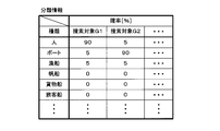
- FIG. 3 is an explanatory diagram of classification information.
- each of the search targets G1 and G2 is one of a plurality of search targets G shown in the water image.
- the number of search target G is one, only the search target G1 is shown in the classification information.
- the types of search target G include people, boats, fishing boats, sailing ships, cargo ships, passenger ships, and the like.
- the classification information indicates the probability that each of these types corresponds to the type of search target G shown in the water image.
- the probability that the type is a person is 90%
- the probability that the type is a boat is 5%
- the probability that the type is a fishing boat is 5%.
- the probability is 0%.
- the search target G2 a plurality of probabilities corresponding to a plurality of types are also shown.
- the search target G1 has the highest probability of being a person
- the search target G2 has the highest probability of being a fishing boat.
- FIG. 4 is an explanatory diagram of the pixel coordinate system.
- the pixel coordinate system is a Cartesian coordinate system composed of an Xp axis and a Yp axis.
- the lower side of the water image is located on the Xp axis of the pixel coordinate system.
- the origin of the pixel coordinate system is located at the center of the lower side of the water image.
- the center of the upper side in the water image is located on the Yp axis of the pixel coordinate system.
- the value of the Yp axis is positive for the center of the upper side in the water image.
- FIG. 5 is an explanatory diagram of area information.
- each of the search targets G1 and G2 is one of the plurality of search targets G shown in the water image.
- the area information indicates the target area of the search target G1 and G2.
- the target area has a rectangular shape.
- each target area of the search target G1, G2, ... Is indicated by the minimum value and the maximum value of the Xp axis and the minimum value and the maximum value of the Yp axis. ..
- the area information can indicate the target area, the information indicating the minimum value and the maximum value of the Xp axis and the minimum value and the maximum value of the Yp axis for each of the search targets G1, G2, ... Not limited to.
- the target detection device 1 adds the target area indicated by the area information and the type and probability indicated by the classification information on the water image of the water image data input to the target detection model 2. Generate additional image data for the image. Specifically, in the additional image, the target area is indicated by a rectangular frame surrounding the search target G, as shown in FIG. Further, regarding the search target G, a label indicating the type corresponding to the highest highest probability among the plurality of probabilities regarding the certainty of classification and the highest probability are arranged in the vicinity of the search target G. In the example of FIG. 2, the type corresponding to the highest probability for the search target G on the left side is a person, and the probability that the search target G on the left side is a person is 70%. Similarly, for the search target G on the right side, the type corresponding to the highest probability is a fishing boat, and the probability that the search target G on the right side is a fishing boat is 80%.
- the target detection device 1 displays an additional image.
- the user of the target detection device 1 confirms the detected search target G in the additional image, and determines, for example, whether or not the flying object F needs to approach the search target G in order to perform a detailed confirmation. ..
- FIG. 6 is a schematic view of the target detection model 2.
- the target detection model 2 is a learning model of machine learning including deep learning, and has a feature extractor 20 and a classification regression device 21.
- Water image data specifically, a plurality of pixel values constituting the water image data are input to the feature extractor 20.
- the feature extractor 20 generates a feature amount map from the water image data by performing a convolution process and a pooling process on the water image data.
- the feature map is a plurality of values represented by a two-dimensional array.
- the feature extractor 20 outputs the extracted feature amount map to the classification regression device 21.
- the classification regression device 21 cuts out the area of the search target G in the feature amount map input from the feature extractor 20.
- the classification regressor 21 calculates the probabilities indicating the certainty of classification for each of the plurality of types based on a plurality of values (a part of the feature amount map) included in the cut out region, and classifies the calculated probabilities indicating the plurality of probabilities. Output information.
- these probabilities are a plurality of probabilities corresponding to a plurality of types such as people, boats and fishing boats.
- a softmax function is used to calculate the probability.
- the classification regression device 21 calculates a probability indicating the certainty of classification for each search target G, and outputs classification information indicating the calculated plurality of probabilities.
- the classification regression device 21 modifies the region of the search target G in order to bring the region of the search target G cut out closer to the actual region.
- the classification regression device 21 returns the correction amount of the region of the search target G.
- the classification regression device 21 outputs region information indicating a target region of a water image corresponding to a region obtained by performing regression. When a plurality of search target G regions are cut out, the classification regression device 21 returns the correction amount of each of the cut out plurality of regions, and obtains a plurality of target regions corresponding to the plurality of regions obtained by performing the regression. Output the indicated area information. When the classification regression device 21 does not detect the region of the search target G, the classification regression device 21 outputs the classification information and the region information indicating that the search target G is not detected.
- Each of the feature extractor 20 and the classification regression device 21 is composed of a convolutional neural network (CNN).
- the CNN has an input layer, a plurality of intermediate layers, and an output layer. There are one or more neurons in each of the input, middle and output layers. The neurons in each layer are unidirectionally connected to the neurons in the previous and next layers with a desired weighting factor and bias.
- a vector having the same number of components as the number of nodes in the input layer is input to the input layer.
- a plurality of pixel values constituting the water image data are input to the input layer of the feature extractor 20.
- a feature map is input to the input layer of the classification regression device 21.
- the data input to each node of the input layer is input to the first intermediate layer.
- the output is calculated using the weighting factor, bias and activation function.
- the calculated value is input to the next intermediate layer.
- the output of the output layer is transmitted to the subsequent layers one after another until the output is obtained.
- the calculation performed in the intermediate layer and the output layer is executed by a processing element such as a CPU (Central Processing Unit), a GPU (Graphic Processing Unit), or a TPU (Tensor processing unit). To.
- a processing element such as a CPU (Central Processing Unit), a GPU (Graphic Processing Unit), or a TPU (Tensor processing unit).
- a convolutional layer, a pooling layer, and the like are included as an intermediate layer or an output layer of the feature extractor 20.
- the intermediate layer or output layer of the classification regression device 21 includes a pooling layer, a fully connected layer (FCL; Fully Connected Layer), and the like.
- ⁇ Generation of target detection model 2> The values of parameters such as the weighting factor and the bias regarding the target detection model 2 are updated based on the training data. This update is the learning of the target detection model 2. By performing the learning, the target detection model 2 is newly generated. For learning, for example, an error backpropagation method is used.
- FIG. 7 is an explanatory diagram of training data.
- the training data includes water image data, type data and area data.
- the type data indicates the type of the search target G shown in the water image of the water image data included in the training data.
- the area data indicates the target area of the search target G reflected in the water image of the water image data included in the training data.
- the water image data included in the training data is the image data of the water image that does not include the horizontal line that is the boundary line between the water surface and the sky.
- the target area is shown in the pixel coordinate system. When the number of search targets G is 2 or more, a plurality of target areas indicated by the area data are associated with each of the plurality of types indicated by the type data.
- a person and a fishing boat are shown as the search target G in the water image of the water image data.
- the type data shows people and fishing boats as types.
- the area data indicates a target area corresponding to a person and a target area corresponding to a fishing boat.
- the target area and the type of the search target G shown in the water image of the water image data are associated with the water image data.
- Target detection model 2 is generated using a large amount of training data.
- the water image data included in the training data is input to the target detection model 2 to acquire the classification information and the area information.
- Each of the acquired classification information and area information is evaluated based on the type indicated by the type data and the area indicated by the area data.
- the value of the parameter of the target detection model 2 is updated. For example, the parameter adjustment amount is calculated using the backpropagation method, and the parameter value is updated based on the calculated adjustment amount.
- FIG. 8 is a block diagram showing a main configuration of the generator 3.
- the generation device 3 is a personal computer, a server, or the like, and generates a new target detection model 2 by learning the target detection model 2, that is, updating the parameter values of the target detection model 2.
- the generation device 3 includes an input unit 30, an output unit 31, an operation unit 32, a storage unit 33, and a control unit 34. These are connected to the internal bus 35.
- Training data is input to the input unit 30 from a device (not shown).
- the control unit 34 acquires training data from the input unit 30.
- the output unit 31 outputs the target detection model 2 according to the instruction of the control unit 34.
- the operation unit 32 has a mouse, a keyboard, a touch panel, and the like, and is operated by the user. When the user performs an operation on the operation unit 32, the operation unit 32 notifies the control unit 34 of information indicating the content of the operation performed by the user.
- the storage unit 33 is a non-volatile memory.
- the target detection model 2 and the computer program P1 are stored in the storage unit 33.
- the control unit 34 has a processing element such as a CPU, GPU, or TPU.
- the processing element of the control unit 34 executes the storage process, the output process, and the model generation process by executing the computer program P1.
- the storage process is a process of storing the training data input to the input unit 30 in the storage unit 33.
- the output process is a process of outputting the target detection model 2 stored in the storage unit 33.
- the model generation process is a process for newly generating the target detection model 2 by updating the value of the parameter of the target detection model 2.
- the number of processing elements included in the control unit 34 may be 2 or more.
- a plurality of processing elements may jointly execute the storage process, the output process, and the model generation process according to the computer program P1.
- the computer program P1 may be provided to the generation device 3 by using a non-temporary storage medium A1 in which the computer program P1 is readablely recorded.
- the storage medium A1 is, for example, a portable memory. Examples of the portable memory include a CD-ROM, a USB (Universal Serial Bus) memory, an SD card, a micro SD card, a compact flash (registered trademark), and the like.
- the processing element of the control unit 34 may read the computer program P1 from the storage medium A1 using a reading device (not shown) and store the read computer program P1 in the storage unit 33. Good.
- the computer program P1 may be provided to the generation device 3 by communication via the communication unit of the generation device 3.
- the processing element of the control unit 34 may acquire the computer program P1 through the communication unit and store the acquired computer program P1 in the storage unit 33.
- control unit 34 executes the storage process.
- the control unit 34 first acquires the training data input to the input unit 30.
- the control unit 34 stores the acquired training data in the storage unit 33, and ends the storage process.
- the control unit 34 executes the output process.
- the control unit 34 reads the target detection model 2 from the storage unit 33.
- the control unit 34 instructs the output unit 31 to output the target detection model 2 read from the storage unit 33 to a device (not shown).
- the control unit 34 ends the output process.
- the target detection model 2 stored in the storage unit 33 of the generation device 3 can be acquired from the generation device 3.
- FIG. 9 is a flowchart showing the procedure of the model generation process.
- the control unit 34 executes the model generation process.
- a certain number is 2 or more.
- the model generation process is executed, the value of the parameter of the target detection model 2 is set.
- the control unit 34 first selects one training data from the plurality of training data stored in the storage unit 33 (step S1). Next, the control unit 34 inputs the water image data selected in step S1 into the target detection model 2 (step S2). Specifically, the control unit 34 inputs a plurality of pixel values constituting the water image data into the target detection model 2. When the water image data is input to the target detection model 2, the control unit 34 calculates in each neuron of the target detection model 2 and outputs the classification information and the area information.
- step S2 the control unit 34 acquires the classification information and the area information output from the target detection model 2 (step S3).
- the control unit 34 evaluates the classification information and the area information acquired in step S3 based on the type data included in the training data selected in step S1 and the type and target area indicated by the area data (step). S4).
- step S4 the control unit 34 evaluates the degree to which the plurality of probabilities indicated by the classification information are appropriate based on the type indicated by the type data. Further, the control unit 34 evaluates the degree to which the area indicated by the area information is appropriate based on the target area indicated by the area data.
- control unit 34 updates the value of the parameter of the target detection model 2 based on the result of the evaluation performed in step S4 (step S5). As a result, a new target detection model 2 is generated.
- step S5 the control unit 34 determines whether or not all the training data stored in the storage unit 33 has been selected (step S6). When the control unit 34 determines that all the training data has not been selected (S6: NO), the control unit 34 executes step S1 again. In step S1 to be executed again, the control unit 34 selects one training data stored in the storage unit 33 and not selected. The control unit 34 keeps updating the parameter values until all the training data are selected.
- control unit 34 determines that all the training data has been selected (S6: YES)
- the control unit 34 deletes all the training data stored in the storage unit 33 (step S7), and ends the model generation process.
- the control unit 34 generates the target detection model 2 based on the plurality of training data.
- the number of times the parameter values are updated using one training data is not limited to one.
- the number of times the parameter values are updated using one training data may be two or more.
- the control unit 34 separately inputs a plurality of water image data included in the plurality of training data into the target detection model 2, and based on the plurality of classification information and the plurality of area information output from the target detection model 2. You may update the value of the parameter.
- the control unit 34 evaluates the degree to which the plurality of probabilities indicated by the plurality of classification information are appropriate.
- the control unit 34 evaluates the degree to which the plurality of regions indicated by the plurality of region information are appropriate based on the plurality of target regions indicated by the plurality of region data.
- the control unit 34 updates the value of the parameter based on the evaluation result by using the backpropagation method.
- a representative value of an appropriate degree for example, an average value of an appropriate degree is used.
- the target detection model 2 may be evaluated using the evaluation data including the water image data, the type data, and the area data.
- the control unit 34 updates the value of the parameter of the target detection model 2 using the plurality of training data, and then inputs the water image data of the evaluation data into the target detection model 2.
- the control unit 34 evaluates the classification information and the area information output from the target detection model 2 by using the type data and the area data included in the evaluation data. In this configuration, if the evaluation does not meet a certain criterion, the control unit 34 may update the parameter values of the target detection model 2 again using the plurality of training data.
- the control unit 34 repeatedly updates the parameter values until the evaluation of the target detection model 2 using the evaluation data satisfies a certain criterion.
- a first method of increasing the water image data for learning there is a method of inverting the left and right of the water image of one water image data.
- a second method of increasing the water image data for learning there is a method of changing at least one of hue, contrast, lightness and saturation in the water image of one water image data.
- a third method of increasing the water image data for learning there is a method of changing a plurality of pixel values constituting one water image data.
- the pixel values of a plurality of pixels are changed for each of red, green, and blue.
- a plurality of pixel values calculated by the product of a plurality of pixel values and a random number are used as a plurality of pixel values constituting new water image data.
- a fourth method of increasing the water image data for learning there is a method of cutting out a part of the water image and returning the scale of the cut water image to the scale of the water image before cutting.
- the plurality of training data used by the generator 3 to generate the target detection model 2 includes training data including water image data generated by the first method, the second method, the third method, or the fourth method. Good.
- FIG. 10 is a block diagram showing a main configuration of the target detection device 1.
- the target detection device 1 detects the search target G based on the water image data.
- the target detection device 1 has four input units 10r, 10f, 11r, 11f, an output unit 12, an input / output unit 13, a reception unit 14, a storage unit 15, a control unit 16, and a display unit 17.
- the four input units 10r, 10f, 11r, 11f, the output unit 12, the input / output unit 13, the reception unit 14, the storage unit 15, and the control unit 16 are connected to the internal bus 18.
- the output unit 12 is further connected to the display 17.
- the flying object F includes a right front camera 40r, a left front camera 40f, a right rear camera 41r, and a left rear camera 41f.
- the input units 10r, 10f, 11r, and 11f of the target detection device 1 are further connected to the right front camera 40r, the left front camera 40f, the right rear camera 41r, and the left rear camera 41f, respectively.
- FIG. 11 is an explanatory diagram of the arrangement of the right front camera 40r, the left front camera 40f, the right rear camera 41r, and the left rear camera 41f.
- the flying object F seen from above is shown.
- the right front camera 40r, the left front camera 40f, the right rear camera 41r, and the left rear camera 41f are located on the right front side, the left front side, the right rear side, and the left rear side in the aircraft F, respectively. It is arranged.
- the right front camera 40r, the left front camera 40f, the right rear camera 41r, and the left rear camera 41f each periodically photograph the water on the right front side, the left front side, the right rear side, and the left rear side of the flying object F.
- each of the right front camera 40r, the left front camera 40f, the right rear camera 41r, and the left rear camera 41f generates water image data of the water image in which the photographed water is captured.
- Each of the right front camera 40r, the left front camera 40f, the right rear camera 41r, and the left rear camera 41f outputs the generated water image data to the input units 10r, 10f, 11r, and 11f each time the water image data is generated. ..
- the control unit 16 acquires water image data from each of the input units 10r, 10f, 11r, and 11f.
- additional image data is generated based on the water image data.
- the output unit 12 outputs the additional image data to the display 17.
- the additional image data includes identification information.
- the identification information indicates the generation source of the water image data used for generating the additional image data.
- the generation source is a right front camera 40r, a left front camera 40f, a right rear camera 41r, or a left rear camera 41f.
- the display 17 displays an additional image of the additional image data.
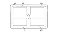
- FIG. 12 is a front view of the display 17. As shown in FIG. 12, the front surface of the display 17 has a rectangular shape.
- the display 17 is provided with four rectangular display screens 50r, 50f, 51r, and 51f on the front surface.
- the display screens 50r and 50f are arranged in the left-right direction, and the display screen 50f is arranged on the left side of the display screen 50r.
- the display screens 51r and 51f are also arranged in the left-right direction, and the display screen 51f is arranged on the left side of the display screen 51r.
- the display screens 50r and 51r are arranged in the vertical direction, and the display screen 51r is arranged below the display screen 50r.
- the display screens 50f and 51f are also arranged in the vertical direction, and the display screen 51f is arranged below the display screen 50f.
- the right front camera 40r, the left front camera 40f, the right rear camera 41r, and the left rear camera 41f correspond to the display screens 50r, 50f, 51r, and 51f, respectively.
- the display 17 adds the input additional image of the input additional image data on the display screens 50r, 50f, 51r, 51f. It is displayed on the display screen corresponding to the generation source indicated by the identification information included in the image data. Therefore, when the additional image data including the identification information indicating the right front camera 40r is input from the output unit 12 to the display unit 17, the display unit 17 displays the additional image of the input additional image data on the display screen 50r. To do.
- Display screens 50r, 50f, 51r, and 50f are arranged on the upper right side, the upper left side, the lower right side, and the lower left side of the arrow, respectively. Therefore, the user can intuitively understand that the display screens 50r, 50f, 51r, and 51f correspond to the right front camera 40r, the left front camera 40f, the right rear camera 41r, and the left rear camera 41f, respectively. it can.
- the target detection device 1 shown in FIG. 10 further has an operation unit (not shown) such as a mouse, a keyboard, or a touch panel.
- the user of the target detection device 1 inputs a value by operating the operation unit.
- the reception unit 14 receives the value input by the user.
- the reception unit 14 notifies the control unit 16 of the accepted value.
- the storage unit 15 is a non-volatile memory.
- the target detection model 2 and the computer program P2 are stored in the storage unit 15.
- the control unit 16 has a processing element such as a CPU, GPU, or TPU.
- the processing element (computer) of the control unit 16 executes the model update process, the data set output process, the four target detection processes, and the threshold value change process by executing the computer program P1.
- the model update process is a process of updating the target detection model 2 stored in the storage unit 15 to the target detection model 2 input to the input / output unit 13.
- the data set includes the water image data input to the target detection model 2 and the classification information and the area information acquired by inputting the water image data into the target detection model 2.
- the data set output process is a process for outputting a data set.
- the target detection process is a process of detecting the search target G based on the water image data and displaying an additional image showing the type of the detected search target G.
- the water image data is input to the target detection model 2 to acquire the classification information and the area information.
- a dataset containing water image data, classification information and area information is generated.
- the generated data set is stored in the storage unit 15.
- Each of the four target detection processes corresponds to the right front camera 40r, the left front camera 40f, the right rear camera 41r, and the left rear camera 41f.
- the search target G is detected based on the water image data input from the corresponding camera in the right front camera 40r, the left front camera 40f, the right rear camera 41r, and the left rear camera 41f. ..
- the control unit 16 determines whether or not to indicate the type using the threshold value.
- the threshold value change process is a process of changing the threshold value used in determining whether or not to indicate the type.
- the threshold value is stored in the storage unit 15.
- the number of processing elements included in the control unit 16 may be 2 or more.
- the plurality of processing elements may jointly execute the model update process, the data set output process, the target detection process, and the threshold value change process according to the computer program P2.
- the computer program P2 may be provided to the target detection device 1 by using a non-temporary storage medium A2 in which the computer program P2 is readablely recorded.
- the storage medium A2 is, for example, a portable memory.
- the processing element of the control unit 16 may read the computer program P2 from the storage medium A2 using a reading device (not shown) and store the read computer program P2 in the storage unit 15. Good.
- the target detection device 1 includes a communication unit that communicates with the external device
- the computer program P2 may be provided to the target detection device 1 by communication via the communication unit of the target detection device 1. In this case, the processing element of the control unit 16 may acquire the computer program P2 through the communication unit and store the acquired computer program P2 in the storage unit 15.
- ⁇ Model update process> For example, when the target detection model 2 is input from the generation device 3 to the input / output unit 13, the control unit 16 executes the model update process. In the model update process, the control unit 16 updates to the target detection model 2 input to the input / output unit 13 stored in the storage unit 15, and ends the model update process.
- ⁇ Data set output processing> For example, when the user performs an operation instructing the output of the data set in the operation unit, the control unit 16 executes the data set output process. In the data set output process, the control unit 16 reads out the data set stored in the storage unit 15. Next, the control unit 16 instructs the input / output unit 13 to output the read data set, and ends the data set output process. The user can generate new training data necessary for retraining the target detection model 2 based on the data set.
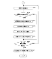
- FIG. 13 is a flowchart showing the procedure of the target detection process.
- the target detection process corresponding to the right front camera 40r will be described.
- the control unit 16 executes the target detection process corresponding to the right front camera 40r.
- the control unit 16 acquires water image data from the input unit 10r (step S11).
- the control unit 16 functions as a data acquisition unit.
- the control unit 16 inputs the water image data acquired in step S11 into the target detection model 2 (step S12).
- the control unit 16 inputs a plurality of pixel values constituting the water image data into the target detection model 2.
- the control unit 16 performs calculation in each neuron of the target detection model 2 and outputs classification information and area information.
- the control unit 16 also functions as a data input unit.
- the control unit 16 After executing step S12, the control unit 16 acquires the classification information and the area information output from the target detection model 2 (step S13). Next, the control unit 16 determines whether or not the search target G has been detected based on the classification information and the area information acquired in step S13 (step S14). When the classification information and the area information acquired in step S13 indicate that the search target G is not detected, the control unit 16 determines that the search target G is not detected. If the classification information and the area information acquired in step S13 do not indicate that the search target G is not detected, the control unit 16 determines that the search target G has been detected.
- control unit 16 determines that the search target G has been detected (S14: YES), the data including the water image data input to the target detection model 2 in step S12 and the classification information and area information acquired in step S13.
- the set is stored in the storage unit 15 (step S15).
- the control unit 16 selects one search target G from the plurality of search target Gs indicated by the classification information and the area information acquired in step S13 (step S16).
- the control unit 16 selects one search target G indicated by the classification information and area information.
- the control unit 16 determines whether or not the maximum probability of the search target G selected in step S16 is equal to or greater than the threshold value based on the classification information acquired in step S13 (step). S17).
- the classification information acquired in step S13 is the classification information shown in FIG. 3
- the search target G1 is selected in step S16
- the highest probability is the probability that the type is a person, that is, 90%.
- the search target G2 is selected in step S16
- the highest probability is the probability that the type is a boat, that is, 90%.
- the control unit 16 also functions as a probability determination unit.
- control unit 16 determines that the maximum probability is equal to or higher than the threshold value (S17: YES)
- the control unit 16 selects the type, the probability, and the color used for displaying the target area (step S18).
- the control unit 16 can select a color according to the highest probability, the type showing the highest probability, or the like.
- FIG. 14 is a chart showing the relationship between the highest probability and color.
- step S18 in the configuration in which the control unit 16 selects a color according to the maximum probability, as shown in FIG. 14, a table showing the relationship between the maximum probability and the color is stored in the storage unit 15.
- the highest probability field shows multiple ranges for the highest probability.
- the color field shows the color corresponding to each of the plurality of ranges shown in the highest probability field.
- step S18 the control unit 16 selects a color corresponding to the range to which the highest probability belongs.
- the threshold value is 60%. Therefore, if the maximum probability is less than 60%, step S18 will not be executed. Therefore, in FIG. 14, the color corresponding to the range where the maximum probability is less than 60% is not shown.
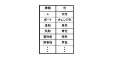
- FIG. 15 is a chart showing the relationship between type and color.
- step S18 in the configuration in which the control unit 16 selects a color according to the type showing the highest probability, as shown in FIG. 15, a table showing the relationship between the type and the color is stored in the storage unit 15. In this table, a type field and a color field are provided. Multiple types are indicated in the type field. The color field shows the color corresponding to each of the plurality of types shown in the type field.
- the control unit 16 selects the color corresponding to the type having the highest probability. In the case where the classification information acquired in step S13 is the classification information shown in FIG. 3, when the search target G1 is selected in step S16, the type corresponding to the highest probability is a person. Therefore, in step S18, the control unit 16 selects the red color corresponding to the person.
- step S18 the control unit 16 displays a label indicating the type corresponding to the highest probability and the highest probability and a frame indicating the target area of the search target G selected in step S16 on the image at the bottom of FIG. Add as shown on the side (step S19).
- the color selected in step S18 is used as the background color of the characters on the label and / or one of the colors of the frame.
- step S19 which is first executed after the execution of the target detection process is started, the control unit 16 adds a label and a frame on the water image of the water image data input to the target detection model 2 in step S12. As a result, additional image data is generated.
- the number of times the control unit 16 executes step S19 may be 2 or more.
- the control unit 16 adds a label and a frame to the additional image of the additional image data generated in the previous step S19. As a result, new additional image data in which a plurality of labels and a plurality of frames are added on the water image is generated.
- step S17 When the control unit 16 determines that the maximum probability is less than the threshold value (S17: NO), or after executing step S19, the control unit 16 selects all the search target Gs indicated by the classification information and the area information acquired in step S13. It is determined whether or not this has been done (step S20). When the control unit 16 determines that all the search target Gs have not been selected (S20: NO), the control unit 16 executes step S16. In step S16 to be executed again, the control unit 16 selects one search target G that is indicated by the classification information and area information acquired in step S13 and is not selected. When the maximum probability of the selected search target G is equal to or greater than the threshold value, a new label and frame are added to the additional image of the additional image data generated in the previous step S19.
- Step S21 the control unit 16 instructs the output unit 12 to output the additional image data generated by executing step S19 to the display unit 17.
- the display 17 displays the additional image of the additional image data input from the output unit 12 on the display screen 50r corresponding to the right front camera 40r.
- the type, probability, and frame shown in the additional image are the contents of the classification information and the area information, that is, the output result of the target detection model 2. Therefore, the display 17 displays the output result of the target detection model 2 by displaying the additional image on the display screen 50r.
- step S21 When the control unit 16 determines that the search target G has not been detected (S14: NO), or after executing step S21, the control unit 16 ends the target detection process. Further, when step S19 is not executed from the start of the target detection process until it is determined that all the search target Gs have been selected in step S20, that is, when the additional image data is not generated. The control unit 16 omits the execution of step S21.
- the control unit 16 may instruct the output unit 12 to output the water image data input to the target detection model 2 in step S12 to the display 17.
- the display 17 displays the water image on the display screen 50r.
- the three target detection processes corresponding to the left front camera 40f, the right rear camera 41r, and the left rear camera 41f are the same as the target detection processes corresponding to the right front camera 40r. Therefore, the description of these target detection processes will be omitted.
- each of the input units 10f, 11r, and 11f is input in the description of the target detection process corresponding to the right front camera 40r.
- Each of the display screens 50f, 51r, and 51f corresponds to the display screen 50r in the description of the target detection process corresponding to the right front camera 40r.
- the control unit 16 acquires four surface image data from the right front camera 40r, the left front camera 40f, the right rear camera 41r, and the left rear camera 41f in the four target detection processes.
- the control unit 16 inputs the acquired four surface image data into the target detection model 2 separately.
- the display 17 corresponds to the camera that outputs the output result of the target detection model 2 and outputs the water image data input to the target detection model 2. Display on the display screen.
- the display 17 is a target detection model 2 that corresponds to the water image data of the right front camera 40r, the left front camera 40f, the right rear camera 41r, and the left rear camera 41f on the display screens 50r, 50f, 51r, and 51f, respectively. Display the output result.
- the user can easily determine the direction of the search target G with respect to the flying object F based on the display screen on which the additional image is displayed. Can be recognized. For example, when the display screen 50r displays the additional image, the user can easily recognize that the search target G shown in the additional image exists in front of the right front of the flying object F.
- FIG. 16 is a flowchart showing the procedure of the threshold value change process.
- the control unit 16 periodically executes the threshold value change process.
- the control unit 16 determines whether or not the reception unit 14 has received the value (step S31).
- the control unit 16 changes the threshold value stored in the storage unit 15 to the value received by the reception unit 14 (step S32).
- the control unit 16 also functions as a change unit.
- the control unit 16 ends the threshold value change process when it is determined that the reception unit 14 is not accepting the value (S31: NO) or after the step S32 is executed.
- the target detection model 2 the relationship between the surface image data and the target area and type of the search target G is learned. Therefore, by inputting the water image data into the target detection model 2, an output result indicating the target area and type of the search target G in the image of the water image data is obtained, and the search target G is accurately detected. Since the display 17 displays an additional image showing the target area and type of the search target G on the water image, the user can easily confirm the position and type of the search target G. Since the type corresponding to the highest probability is displayed in the additional image, it is easier to confirm the type of the search target G.
- the type of search target G whose maximum probability is equal to or greater than the threshold value is displayed, and the type of search target G whose maximum probability is less than the threshold value is not displayed. Therefore, since the number of search target Gs to be confirmed is small, the user can efficiently find the search target G.
- the type, the highest probability, and the target area are displayed using the color corresponding to the highest probability, the user can find the search target G more efficiently. Since the user can freely change the threshold value according to the weather, brightness, and the like around the flying object F, the convenience of the target detection device 1 is high.
- the storage unit 15 of the target detection device 1 may store four target detection models 2.
- each of the four processing elements executes the four target detection models 2.
- four target detection models 2 are used. Therefore, even when one processing element performs the calculation in one target detection model 2, the other processing elements can perform the calculation in the other target detection model 2. In this case, the four target detection processes are efficiently executed.
- the contents of the four target detection models 2 may be common or different from each other. When the four target detection models 2 are different from each other, the learning of the four target detection models 2 is performed separately.
- the display 17 of the target detection device 1 in the first embodiment displays an additional image, and the additional image shows the type and the maximum probability of the search target G.
- the items displayed in the additional image are not limited to the type of search target G and the highest probability.
- the difference between the second embodiment and the first embodiment will be described. Since the other configurations other than the configurations described later are common to the first embodiment, the same reference numerals as those of the first embodiment are assigned to the components common to the first embodiment, and the description thereof is omitted. To do.
- FIG. 17 is a block diagram showing a main configuration of the target detection device 1 according to the second embodiment.
- the flying object F in the second embodiment includes an altimeter 42, a heading indicator 43, and a GPS (in addition to the target detection device 1, the right front camera 40r, the left front camera 40f, the right rear camera 41r, and the left rear camera 41f).
- Global Positioning System The receiver 44 is provided.
- the target detection device 1 according to the second embodiment has three input units 60, 61, 62 in addition to the components included in the target detection device 1 according to the first embodiment.
- the input units 60, 61, 62 are connected to the internal bus 18.
- the inputs 60, 61, and 62 are further connected to the altimeter 42, the heading indicator 43, and the GPS receiver 44, respectively.
- the altimeter 42 periodically measures the altitude, that is, the distance from the water surface to the flying object F.
- the altimeter 42 outputs altitude information indicating the measured altitude to the input unit 60 each time the altitude is measured.
- the control unit 16 acquires altitude information from the input unit 60.
- the altimeter 42 may be configured to measure the altitude based on the absolute pressure of the atmosphere, or a radio wave reflected on the water surface may fly after emitting a vertical radio wave from the flying object F toward the water surface.
- the altitude may be measured based on the time required to reach the body F.
- the heading indicator 43 periodically measures the flight direction, specifically, the angle formed by the north and the nose of the flying object F.
- the flight direction is a clockwise angle with respect to the north. Therefore, when the nose of the aircraft F is facing east, the flight direction is 90 degrees. When the nose of the aircraft F is facing west, the flight direction is 270 degrees.
- the heading indicator 43 is realized by using, for example, a gyroscope. Each time the heading indicator 43 measures the flight direction, it outputs the direction information indicating the measured flight direction to the input unit 61.
- the control unit 16 acquires directional information from the input unit 61.
- the GPS receiver 44 periodically calculates the position of the flying object, which is the position of the flying object F, based on the signals received from the plurality of GPS satellites by the GPS receiver.
- the position of the aircraft is represented by latitude and longitude.
- the GPS receiver outputs the flight body position information indicating the calculated flight body position to the input unit 62.
- ⁇ Target detection process> 18 and 19 are flowcharts showing the procedure of the target detection process.
- the target detection process corresponding to the right front camera 40r will be described.
- the control unit 16 executes the target detection process corresponding to the right front camera 40r when the water image data of the input unit 10r is input from the right front camera 40r.
- a plurality of processes are added to the target detection process according to the first embodiment. Therefore, the description of the target detection process in the first embodiment included in the target detection process in the second embodiment, that is, steps S11 to S21 will be omitted.
- step S15 the control unit 16 acquires altitude information from the input unit 60 (step S41), acquires directional information from the input unit 61 (step S42), and acquires aircraft body position information from the input unit 62. (Step S43).
- the control unit 16 executes step S16 after executing step S43.
- the control unit 16 determines that the maximum probability of the search target G selected in step S16 is equal to or greater than the threshold value (S17: YES)
- the control unit 16 selects the search target G in step S16 based on the area information acquired in step S13.
- the center coordinates of (step S44) are calculated.
- the center coordinates are the coordinates of the pixel coordinate system.
- the center coordinates are the average value of the minimum and maximum values of the Xp axis. It is represented by the average value of the minimum value and the maximum value of the Yp axis.
- the control unit 16 determines the altitude, the flight direction, and the position of the flying object indicated by the altitude information, the directional information, and the flying object position information acquired in steps S41, S42, and S43, and the center coordinates of the search target G calculated in step S44. Based on the above, the search target position, which is the position of the search target G, is calculated (step S45). The search target position is represented by latitude and longitude. The calculation of the search target position will be described later.
- the control unit 16 executes step S18 after executing step S45.
- the area information is the output result of the target detection model 2, and the coordinates of the search target G indicated by the area information are the coordinates on the water image because they are represented by the pixel coordinate system. Therefore, the control unit 16 also functions as a calculation unit.
- step S19 of the target detection process in the second embodiment the control unit 16 selects not only the type corresponding to the highest probability and the highest probability, but also the label indicating the search target position calculated in step S45 and the target position in step S16.
- a frame indicating the target area of the search target G is added.
- the control unit 16 executes step S21, the display 17 displays an additional image on the display screen 50r. In this additional image, not only the type corresponding to the highest probability and the highest probability, but also the position of the search target G is shown.
- the three target detection processes corresponding to the left front camera 40f, the right rear camera 41r, and the left rear camera 41f are the same as the target detection processes corresponding to the right front camera 40r. Therefore, the description of these target detection processes will be omitted.
- each of the input units 10f, 11r, and 11f is input in the description of the target detection process corresponding to the right front camera 40r.
- Each of the display screens 50f, 51r, and 51f corresponds to the display screen 50r in the description of the target detection process corresponding to the right front camera 40r.
- FIG. 20 is an explanatory diagram of the display of the additional image.
- FIG. 20 shows a display screen 50r of the display device 17 when step S21 of the target detection process corresponding to the right front camera 40r is executed.
- An additional image is displayed on the display screen 50r.
- the latitude and longitude are shown in parentheses.
- the value on the left in parentheses indicates the latitude.
- the value on the right in parentheses indicates longitude.
- the processing element of the control unit 16 changes the additional image displayed on the display screen 50r by executing the computer program P2. Execute image change processing.
- This image change process corresponds to the right front camera 40r.
- Object selection is realized by selection using a pointer, tapping on the display screen 50r, or the like.
- the additional image data generated in step S19 of the target detection process corresponding to the right front camera 40r is stored in the storage unit 15.
- the control unit 16 instructs the output unit 12 to output the additional image data generated in step S19 of the previous target detection process to the display unit 17.
- the additional image of the additional image data generated in step S19 of the previous target detection process for example, the additional image shown at the lower side of FIG. 20 is displayed.
- Objects are displayed on the left side and the right side of the additional image on the display screen 50r.
- the control unit 16 ends the image change process after instructing the output unit 12 to output the additional image data.
- control unit 16 When the object on the right side of the display screen 50r is further selected, the control unit 16 again executes the image change process corresponding to the right front camera 40r. In this image change process, the control unit 16 causes the output unit 12 to output the additional image data generated before the additional image data of the additional image displayed on the display screen 50r. As a result, the additional image of the additional image data generated in step S19 of the previous target detection process is displayed on the display screen 50r.
- the control unit 16 executes the image change process corresponding to the right front camera 40r.
- the control unit 16 causes the output unit 12 to output the additional image data generated after the additional image data of the additional image displayed on the display screen 50r.
- the additional image of the additional image data generated in step S19 of the target detection process later is displayed on the display screen 50r.
- the control unit 16 executes the image change process corresponding to the right front camera 40r, whereby the user confirms the additional images of all the additional image data generated by the image change process corresponding to the right front camera 40r. can do.
- the latest additional image and the additional image changed by the image change process may be displayed on the display screen 50r.
- ⁇ Other image change processing> When the user selects a triangular object displayed on each of the display screens 50f, 51r, 51f, the processing element of the control unit 16 displays the display screens 50f, 51r, 51f by executing the computer program P2. Execute the image change process to change the displayed additional image.
- the image change process for changing the additional image displayed on each of the display screens 50f, 51r, and 51f corresponds to the left front camera 40f, the right rear camera 41r, and the left rear camera 41f.
- Each of the three image change processes corresponding to the left front camera 40f, the right rear camera 41r and the left rear camera 41f is executed in the same manner as the image change process corresponding to the right front camera 40r.
- a plurality of processing elements may jointly execute four image change processes according to the computer program P2.
- the control unit 16 calculates the search target position, and the search target position calculated by the control unit 16 is displayed by the display 17. Therefore, when it is necessary for the flight body F to head toward the search target G, the user instructs the operator of the flight body F to quickly reach the search target G based on the search target position calculated by the control unit 16. be able to.
- the target detection device 1 according to the second embodiment similarly exhibits the effect of the target detection device 1 according to the first embodiment.
- the control unit 16 of the target detection device 1 in the first embodiment may execute four image change processes as in the second embodiment.
- FIG. 21 is a first explanatory diagram of numerical values used for calculating the search target position.
- the pixel coordinate system is shown on the upper side of FIG. 21.
- the center coordinates of the search target G in the pixel coordinate system are represented by (Px, Py).
- the value on the Xp axis is shown on the left side in parentheses, and the value on the Yp axis is shown on the right side in parentheses.
- the maximum value of the Xp axis is Wx
- the minimum value of the Xp axis is ⁇ Wx
- the minimum value of the Yp axis is zero
- the maximum value of the Yp axis is Hy.
- Wx and Hy are known numerical values that are set in advance.
- Px and Py are known numerical values calculated in step S45.
- the lower side of FIG. 21 shows the distance coordinate system converted from the pixel coordinate system.
- the distance coordinate system is an orthogonal coordinate system composed of an Xd axis and a Yd axis, and is a coordinate system in which the unit of one scale is meters.
- the Xd axis corresponds to the Xp axis of the pixel coordinate system.
- the Yd axis corresponds to the Yp axis of the pixel coordinate system.
- the center coordinates of the search target G in the distance coordinate system are represented by (Dx, Dy).
- the value on the Xd axis is shown on the left side in parentheses, and the value on the Yd axis is shown on the right side in parentheses.
- Each of Dx and Dy is calculated based on known numerical values.
- FIG. 22 is a second explanatory diagram of numerical values used for calculating the search target position.
- FIG. 22 shows the flying object F and the search target G as seen from the front side.
- Hf is the altitude of the flying object F, which is a known value measured by the altimeter 42.
- L is the distance between the flying object F and the search target G in the left-right direction of the flying object F, and is calculated based on a known numerical value.
- ⁇ t is an angle that can be photographed by the right front camera 40r with respect to the vertical direction of the flying object F, and is a known value.
- ⁇ g is an angle from the upper side to the search target position in the water image of the right front camera 40r with respect to the vertical direction of the flying object F, and is calculated based on a known value.
- FIG. 23 is a third explanatory diagram of numerical values used for calculating the search target position.
- FIG. 23 shows the flying object F and the search target G as viewed from above.
- ⁇ f is the flight direction and is a known value measured by the heading indicator 43.
- the direction on the left side of the water image coincides with the flight direction.
- ⁇ t is an angle formed by two directions corresponding to the left side and the right side in the water image, and is a known value.
- ⁇ c is an angle formed by the direction on the left side and the axial direction of the right front camera 40r in the water image, and is a known value.
- the axial direction of the right front camera 40r is the axial direction of the lens of the right front camera 40r.
- ⁇ g is an angle from the axial direction of the right front camera 40r to the search target position, and is calculated based on a known value.
- ⁇ f, ⁇ t, ⁇ c and ⁇ g are angles viewed from above the flying object F.
- the angle ⁇ p per pixel on the Yp axis is calculated by the following formula using Hy and ⁇ t.
- ⁇ g ⁇ t- ( ⁇ p ⁇ Py) " ⁇ " Represents a product.
- Dy shown on the lower side of FIG. 21 is calculated by the following formula using Hf and ⁇ g.
- Dy Hf / tan ( ⁇ g)
- Dx shown on the lower side of FIG. 21 is calculated by the following formula using Dy, Wx and Px.
- Dx Dy / (Wx ⁇ Px)
- ⁇ g shown in FIG. 23 is calculated by the following formula using Dx and Dy.
- ⁇ g arctan (Dx / Dy)
- L shown in FIG. 22 is calculated by the following formula using Dy and ⁇ g.
- L Dy / cos ( ⁇ g)
- the angle ⁇ n from the north to the search target G is expressed by the following equation using ⁇ f, ⁇ c and ⁇ g.
- ⁇ n ⁇ f + ⁇ c + ⁇ g
- the latitude and longitude of the aircraft position are described as Fa and Fb, respectively.
- Fa and Fb are known values calculated by the GPS receiver 44.
- the radius of the earth is described as Re.
- Re is also a known value.
- the latitude and longitude of the search target position are described as Ga and Gb, respectively.
- Ga is calculated by the following formula using Fa, L, ⁇ n and Re.
- Ga Fa + (L ⁇ sin ( ⁇ n) ⁇ 360 / Re)
- Gb is calculated by the following formula using Fa, Fb, L, ⁇ and Re.
- Gb Fb + ((L ⁇ cos ( ⁇ n) / cos (Fa)) ⁇ (360 / Re))
- step S45 of the target detection process corresponding to the right front camera 40r the control unit 16 uses the altitude, the flight direction, the position of the flying object, the center coordinates of the search target G, and the plurality of equations described above to obtain the search target position. That is, Ga and Gb can be calculated.
- step S45 of the target detection process corresponding to each of the left front camera 40f, the right rear camera 41r and the left rear camera 41f the control unit 16 performs the search performed in step S45 of the target detection process corresponding to the right front camera 40r. The same calculation as the calculation of the target position is performed.
- the notification of the type of the search target G to the user is realized by displaying an additional image indicating the type on the display device 17.
- the notification to the user of the type of the search target G is not limited to the notification by display.
- the differences between the third embodiment and the first embodiment will be described. Since the other configurations other than the configurations described later are common to the first embodiment, the same reference numerals as those of the first embodiment are assigned to the components common to the first embodiment, and the description thereof is omitted. To do.
- FIG. 24 is a block diagram showing a main configuration of the target detection device 1 according to the third embodiment.
- the target detection device 1 according to the third embodiment has an output unit 63 and a voice notification unit 64 in addition to the components included in the target detection device 1 according to the first embodiment.
- the output unit 63 is separately connected to the internal bus 18 and the voice notification unit 64.
- the output unit 63 outputs voice data to the voice notification unit 64 according to the instruction of the control unit 16.
- the audio data indicates the type, maximum probability, and position of the search target G displayed in the additional image, and also includes the display screen on which the additional image is displayed, the source of the water image data, and the shooting direction of the source. At least one of is shown.
- the display screen is one of the display screens 50r, 50f, 51r, and 51f.
- the generator is one of the right front camera 40r, the left front camera 40f, the right rear camera 41r, and the left rear camera 41f.
- the voice notification unit 64 is, for example, a speaker, and when voice data is input from the output unit 63, the voice notification unit 64 notifies the content indicated by the input voice data by voice.
- FIG. 25 is a flowchart showing the procedure of the target detection process.
- the control unit 16 executes the target detection process corresponding to the right front camera 40r when the water image data of the input unit 10r is input from the right front camera 40r.
- the target detection process according to the third embodiment a plurality of processes are added to the target detection process according to the first embodiment. Therefore, the description of the target detection process in the first embodiment included in the target detection process in the third embodiment, that is, steps S11 to S21 will be omitted.
- the control unit 16 generates voice data after executing step S21 (step S51).
- the audio data indicates the type, maximum probability, and position of the search target G displayed on the additional image, and is included in the display screen on which the additional image is displayed, the source of the water image data, and the shooting direction of the generation source. At least one is shown. Examples of the position include the center, upper side, lower side, left side and right side of the additional image.
- the target detection process corresponding to the right front camera 40r, the display screen, the generation source, and the shooting direction indicated by the audio data are the display screen 50r, the right front camera 40r, and the right front, respectively.
- control unit 16 instructs the output unit 63 to output the voice data generated in step S51 to the voice notification unit 64 (step S52).
- voice notification unit 64 notifies the content indicated by the voice data by voice.
- control unit 16 determines that the search target G has not been detected (S14: NO), or after executing step S43, the control unit 16 ends the target detection process.
- step S19 is not executed from the start of the target detection process until it is determined that all the search targets G have been selected in step S20, that is, if the additional image data is not generated, the control unit In step 16, execution of steps S21, S51, and S52 is omitted.
- the three target detection processes corresponding to the left front camera 40f, the right rear camera 41r, and the left rear camera 41f are the same as the target detection processes corresponding to the right front camera 40r. Therefore, the description of these target detection processes will be omitted.
- each of the input units 10f, 11r, and 11f is input in the description of the target detection process corresponding to the right front camera 40r.
- Each of the display screens 50f, 51r, and 51f corresponds to the display screen 50r in the description of the target detection process corresponding to the right front camera 40r.
- the voice notification unit 64 notifies the type corresponding to the highest probability in the classification information, and displays the display screen corresponding to the highest probability, the camera corresponding to this display screen, and the camera. At least one of the directions taken by the camera is notified by voice.
- the target detection device 1 according to the third embodiment not only the additional image showing the target area and type of the search target G is displayed, but also the type of the search target G and the information related to the search target G are voice notification units. Notified by 64. Therefore, the user can find the search target more reliably.
- the target detection device 1 according to the third embodiment similarly exhibits the effect of the target detection device 1 according to the first embodiment.
- the target detection device 1 in the second embodiment has an output unit 63 and a voice notification unit 64 as in the third embodiment, and may notify the type of the search target G, the maximum probability, and the like by voice. ..
- the threshold value is changed to the value received by the reception unit 14.
- the configuration for changing the threshold value is not limited to the configuration for accepting a value.
- the differences between the fourth embodiment and the first embodiment will be described. Since the other configurations other than the configurations described later are common to the first embodiment, the same reference numerals as those of the first embodiment are assigned to the components common to the first embodiment, and the description thereof is omitted. To do.
- FIG. 26 is a block diagram showing a main configuration of the target detection device 1 according to the fourth embodiment.
- the flying object F in the fourth embodiment includes a weather radar 45 in addition to the target detection device 1, the right front camera 40r, the left front camera 40f, the right rear camera 41r, and the left rear camera 41f.
- the target detection device 1 in the fourth embodiment has other components other than the reception unit 14 among the components of the target detection device 1 in the first embodiment.
- the target detection device 1 in the fourth embodiment further has an input unit 65.
- the input unit 65 is separately connected to the internal bus 18 and the weather radar 45.
- the weather radar 45 periodically detects the weather around the aircraft F. For example, the weather radar 45 emits electromagnetic waves and detects the weather based on the frequency of the electromagnetic waves reflected by the object. Each time the weather radar 45 detects the weather around the aircraft F, the weather radar 45 outputs the weather information indicating the detected weather to the input unit 65.
- the control unit 16 acquires weather information from the input unit 65.
- the weather includes sunny, cloudy, rainy and snowy.
- FIG. 27 is a flowchart showing the procedure of the threshold value change process.
- the control unit 16 periodically executes the threshold value change process as in the first embodiment.
- the control unit 16 first acquires weather information from the input unit 65 (step S61).
- the control unit 16 also functions as an information acquisition unit.
- the control unit 16 changes the threshold value based on the weather information acquired in step S61 (step S62).
- the control unit 16 changes the threshold value stored in the storage unit 15, for example, by using a table showing the relationship between the weather and the candidate value of the threshold value.
- FIG. 28 is a chart showing the relationship between the weather and the candidate value of the threshold value.
- a table showing the relationship between the weather and the candidate value of the threshold value is stored in the storage unit 15.
- a weather field and a candidate value field are provided. Multiple weathers are shown in the weather field.
- the weather is shown as sunny, cloudy, rainy and snowy.
- the candidate value field the candidate value of the threshold value corresponding to each of the plurality of weathers shown in the weather field is shown.
- the candidate values of the threshold values corresponding to sunny, cloudy, rain and snow are 80%, 70%, 60% and 60%, respectively.
- step S62 of the threshold value change process the control unit 16 changes the threshold value to a candidate value corresponding to the weather indicated by the weather information acquired in step S61.
- the control unit 16 changes the threshold value to a candidate value corresponding to sunny, that is, 80%.
- the control unit 16 ends the threshold value change process.
- the target detection device 1 according to the fourth embodiment since the threshold value is changed according to the weather around the flying object F, the target area and type of the search target G are appropriately shown in the additional image.
- the target detection device 1 in the fourth embodiment has other effects other than the effect obtained by changing the threshold value to the value received by the reception unit 14 among the effects performed by the target detection device 1 in the first embodiment. Play in the same way.
- the target detection device 1 in the fourth embodiment may further have a receiving unit (not shown) that receives the weather and the value from the user. For example, when the reception unit receives the weather and the value, the control unit 16 changes the candidate value of the weather threshold value received by the reception unit to the value received by the reception unit.
- the target detection device 1 may have a wireless communication unit that communicates wirelessly.
- the control unit 16 of the target detection device 1 may acquire the weather information from the wireless communication unit instead of the weather radar 45.
- a weather detection unit that detects the weather based on the detection results of a rain sensor that detects rainfall and a brightness sensor that detects the brightness around the air vehicle F is provided on the air vehicle F instead of the weather radar 45. It may have been.
- the weather detection unit periodically outputs the weather information indicating the detected weather to the input unit 65.
- the control unit 16 may change the threshold value according to the weather information indicating the weather around the flying object F, as in the fourth embodiment.
- the threshold value is changed to the value received by the reception unit 14, and in the fourth embodiment, the threshold value is changed according to the weather around the flying object F.
- the configuration for changing the threshold value is not limited to the configuration for changing the value received by the reception unit 14 or the configuration for changing the threshold value according to the weather around the flying object F.
- the differences between the fifth embodiment and the first embodiment will be described. Since the other configurations other than the configurations described later are common to the first embodiment, the same reference numerals as those of the first embodiment are assigned to the components common to the first embodiment, and the description thereof is omitted. To do.
- FIG. 29 is a flowchart showing the procedure of the target detection process according to the fifth embodiment.
- the control unit 16 executes the target detection process corresponding to the right front camera 40r when the water image data of the input unit 10r is input from the right front camera 40r.
- the target detection process according to the fifth embodiment one process is added to the target detection process according to the first embodiment. Therefore, the description of the target detection process in the first embodiment included in the target detection process in the fourth embodiment, that is, steps S11 to S21 will be omitted.
- control unit 16 shown in FIG. 10 sets the threshold value stored in the storage unit 15 to the highest probability among the plurality of probabilities related to the search target G selected in step S16.
- the value is changed according to (step S71).
- the control unit 16 changes the threshold value stored in the storage unit 15, for example, by using a table showing the relationship between the type and the candidate value of the threshold value.
- FIG. 30 is a chart showing the relationship between the type and the candidate value of the threshold value.
- a table showing the relationship between the type and the candidate value of the threshold value is stored in the storage unit 15.
- a type field and a candidate value field are provided. Multiple types are indicated in the type field.
- people, boats, fishing boats, sailing boats, and the like are shown as types.
- the candidate value field the candidate values of the threshold values corresponding to each of the plurality of types shown in the type field are shown.
- the control unit 16 changes the threshold value to a candidate value corresponding to the type of the highest probability.
- the classification information acquired in step S13 is the classification information shown in FIG.
- step S71 the control unit 16 changes the threshold value to a candidate value corresponding to a person.
- the candidate value of the threshold value corresponding to the person is 60%.
- step S17 the control unit 16 determines whether or not the maximum probability is equal to or greater than the threshold value changed in step S71. When the maximum probability is equal to or greater than the threshold value, a label and a frame are added to the image in step S19, and an additional image is generated.
- the three target detection processes corresponding to the left front camera 40f, the right rear camera 41r, and the left rear camera 41f are the same as the target detection processes corresponding to the right front camera 40r. Therefore, the description of these target detection processes will be omitted.
- each of the input units 10f, 11r, and 11f is input in the description of the target detection process corresponding to the right front camera 40r.
- Each of the display screens 50f, 51r, and 51f corresponds to the display screen 50r in the description of the target detection process corresponding to the right front camera 40r.
- the search target G when the type with the highest probability for one search target G is a type with a low threshold candidate value, the search target G is emphasized by the label and the frame in the additional image. Probability is high.
- the candidate value of the threshold value corresponding to a person is low, and the candidate value of the threshold value corresponding to a cargo ship and a passenger ship is high. Therefore, the type of highly important search target G corresponding to the highest probability, for example, the search target G that is likely to require rescue, is likely to be highlighted by the label and frame. As a result, the search target G is more reliably discovered by the user.
- the target detection device 1 in the fifth embodiment has other effects other than the effect obtained by changing the threshold value to the value received by the reception unit 14 among the effects performed by the target detection device 1 in the first embodiment. Play in the same way.
- the target detection device 1 according to the fifth embodiment may further have a receiving unit (not shown) that receives a type and a value from the user. For example, when the reception unit accepts a type and a value, the control unit 16 changes the candidate value of the threshold value of the type accepted by the reception unit to the value accepted by the reception unit. Further, in the target detection device 1 according to the fifth embodiment, the control unit 16 does not execute the threshold value change process. Further, in the target detection device 1 in the second and third embodiments, the control unit 16 may change the threshold value according to the type corresponding to the highest probability, as in the fifth embodiment.
- the display 17 mainly displays the additional image.
- the display 17 may be configured to display both a water image and an additional image.
- the differences between the sixth embodiment and the first embodiment will be described. Since the other configurations other than the configurations described later are common to the first embodiment, the same reference numerals as those of the first embodiment are assigned to the components common to the first embodiment, and the description thereof is omitted. To do.
- FIG. 31 is a front view of the display 17 according to the sixth embodiment.
- the display 17 according to the sixth embodiment is provided with four rectangular display screens 50r, 50f, 51r, and 51f, as in the first embodiment.
- the display 17 according to the sixth embodiment is further provided with four rectangular display screens 70r, 70f, 71r, and 71f.
- the display screens 50r, 50f, 51r, 51f, 70r, 70f, 71r, and 71f are arranged in a grid pattern.
- the display screens 50f, 70f, 50r, and 70r are arranged in this order from the left side.
- the display screens 51f, 71f, 51r, 71r are arranged in this order from the left side.
- each of the display screens 50r, 50f, 51r, and 51f corresponds to the right front camera 40r, the left front camera 40f, the right rear camera 41r, and the left rear camera 41f, and displays additional images. ..
- Each of the display screens 70r, 70f, 71r, and 71f corresponds to the right front camera 40r, the left front camera 40f, the right rear camera 41r, and the left rear camera 41f, and displays a water image.
- the additional image data includes identification information indicating the generation source of the water image data used for generating the additional image data.
- the water image data also includes the identification information indicating the generation source.
- the generation source is a right front camera 40r, a left front camera 40f, a right rear camera 41r, or a left rear camera 41f.
- the display 17 When the additional image data is input to the display 17 from the output unit 12, the display 17 adds the input additional image of the input additional image data on the display screens 50r, 50f, 51r, 51f. It is displayed on the display screen corresponding to the generation source indicated by the identification information included in the image data.
- the display 17 displays the water image of the input water image data on the input water on the display screens 70r, 70f, 71r, 71f. It is displayed on the display screen corresponding to the generation source indicated by the identification information included in the image data.
- Display screens 50r, 50f, 51r, and 50f are arranged on the upper right side, the upper left side, the lower right side, and the lower left side of the arrow, respectively. Therefore, the user can intuitively understand that the display screens 50r, 50f, 51r, and 50f correspond to the right front camera 40r, the left front camera 40f, the right rear camera 41r, and the left rear camera 41f, respectively. it can. Further, display screens 70r, 70f, 71r, and 70f are arranged on the upper right side, the upper left side, the lower right side, and the lower left side of the arrow, respectively. Therefore, the user can intuitively understand that the display screens 70r, 70f, 71r, and 71f correspond to the right front camera 40r, the left front camera 40f, the right rear camera 41r, and the left rear camera 41f, respectively. it can.
- the processing element of the control unit 16 shown in FIG. 10 further executes four image display processes for displaying a water image by executing the computer program P2.
- Each of the four image display processes corresponds to the right front camera 40r, the left front camera 40f, the right rear camera 41r, and the left rear camera 41f.
- the water image of the water image data input from the corresponding camera among the right front camera 40r, the left front camera 40f, the right rear camera 41r and the left rear camera 41f is displayed on the display 17.
- the control unit 16 has a plurality of processing elements, the plurality of processing elements may jointly execute the image display processing according to the computer program P2.
- FIG. 32 is a flowchart showing the procedure of the image display processing.
- the control unit 16 executes an image display process corresponding to the right front camera 40r when the water image data is input from the right front camera 40r to the input unit 10r.
- the control unit 16 acquires water image data from the input unit 10r (step S81).
- the control unit 16 instructs the output unit 12 to output the seaplane image data acquired in step S81 to the display 17 (step S82).
- the display 17 displays the water image of the water image data input from the output unit 12 on the display screen 70r corresponding to the right front camera 40r.
- the control unit 16 ends the image display process.
- the three image display processes corresponding to the left front camera 40f, the right rear camera 41r, and the left rear camera 41f are the same as the image display processes corresponding to the right front camera 40r. Therefore, the description of these image display processes will be omitted.
- each of the input units 10f, 11r, and 11f is input in the description of the image display process corresponding to the right front camera 40r.
- Each of the display screens 70f, 71r, and 71f corresponds to the display screen 70r in the description of the image display process corresponding to the right front camera 40r.
- ⁇ Target detection process> The right front camera 40r photographs the water surface at short time intervals and outputs the water surface image data. Therefore, the control unit 16 outputs the water image data to the input unit 10r from the start of the execution of the target detection process corresponding to the right front camera 40r to the end of the target detection process. Will be done. In this configuration, when the right front camera 40r outputs the water image data to the input unit 10r after the target detection process corresponding to the right front camera 40r is completed, the control unit 16 is the target corresponding to the right front camera 40r. Execute the detection process again.
- the time required for the image display processing corresponding to the right front camera 40r is sufficiently shorter than the time required for the target detection processing corresponding to the right front camera 40r. Therefore, every time the right front camera 40r outputs the water image data to the input unit 10r, the image display process is executed and the water image is displayed on the display screen 70r. On the other hand, additional image data is generated in the target detection process. Therefore, the time interval for updating the water image on the display screen 70r is shorter than the time interval for updating the additional image on the display screen 50r.
- the operations of the left front camera 40f, the right rear camera 41r, and the left rear camera 41f are the same as those of the right front camera 40r.
- the three image display processes corresponding to the left front camera 40f, the right rear camera 41r, and the left rear camera 41f are executed in the same manner as the image display processing corresponding to the right front camera 40r. Further, the execution of the three target detection processes corresponding to the left front camera 40f, the right rear camera 41r and the left rear camera 41f is started under the same conditions as the target detection process corresponding to the right front camera 40r. Therefore, the time interval for updating the water image on each of the display screens 70f, 71r, and 71f is shorter than the time interval for updating the additional image on the display screens 50f, 51r, and 51f.
- the water image is displayed in real time on the display screens 70r, 70f, 71r, 71f. Further, each time the additional image data is generated, the additional image displayed on the display screens 50r, 50f, 51r, 51f is updated. Therefore, effective display is realized.
- the target detection device 1 according to the sixth embodiment similarly exhibits the effect of the target detection device 1 according to the first embodiment.
- the display 17 may display both the water image and the additional image as in the sixth embodiment.
- the water image data of the water image in which a person exists is described as the water image data of a person.
- FIG. 33 is an explanatory diagram of the generation of water image data for learning in the seventh embodiment.
- the storage unit 33 of the generation device 3 shown in FIG. 8 contains a generation model 80 that generates water image data of a person and an identification model that identifies the authenticity of the input water image data of the person. 81 is stored.
- True means that the input human water image data is real human water image data not generated by the generative model 80.
- False means that the input water image data is the water image data of a fake person generated by the generative model 80.
- Each of the generation model 80 and the discriminative model 81 is a learning model composed of a neural network, and has an input layer, an intermediate layer, and an output layer as in the target detection model 2.
- the calculations performed in the intermediate layer and the output layer are performed by a processing element such as a CPU, GPU or TPU.
- the generative model 80 and the discriminative model 81 constitute so-called GANs (Generative Adversarial Networks), and the generative model 80 and the discriminative model 81 are trained in the GANs.
- GANs Generic Adversarial Networks
- the water image data of a person is acquired from the generative model 80.
- a one-dimensional noise vector is input to the generative model 80.
- the noise vector corresponds to predetermined data.
- Each value of the noise vector is a value in the range of -1 to +1 and is set at random.
- the generation model 80 When the noise vector is input to the generation model 80, the generation model 80 generates the water image data of the person and outputs the water image data of the generated person.
- Water image data of a person is also input to the identification model 81.
- a plurality of pixel values constituting the water image data are input to the generation model 80.
- the identification model 81 identifies the authenticity of the input water image data and outputs the identification result. Therefore, the discriminative model 81 outputs true when the input water image data is real person water image data, and false when the input water image data is fake person water image data. Output.
- the processing element of the control unit 34 executes a computer program P1 to perform a second storage process for storing real human water image data not generated by the generation model 80, and a generation model 80. And the learning process for learning the discriminative model 81.
- the control unit 34 executes a second storage process when a plurality of water image data in which a person exists in the water image is input to the input unit 30.
- the control unit 34 first acquires a plurality of water image data input to the input unit 30 as water image data of a real person.
- the control unit 34 stores the acquired plurality of water image data in the storage unit 33, and ends the storage process.
- the control unit 34 executes the learning process.
- the control unit 34 first learns the discriminative model 81 using a plurality of water image data (genuine) acquired in the second storage process. Specifically, the control unit 34 inputs the water image data of the person acquired in the second storage process into the identification model 81. As a result, the discriminative model 81 outputs the discriminative result.
- the control unit 34 updates the value of the parameter of the identification model 81 so that the identification result output from the identification model 81 becomes true.
- the value of the parameter of the discriminative model 81 is repeatedly updated using the plurality of water image data acquired in the second storage process.
- the control unit 34 learns the discriminative model 81 using the water image data (fake) of the person output from the generative model 80. In this learning, the control unit 34 inputs a noise vector to the generative model 80. As a result, the generative model 80 outputs human water image data. Next, the control unit 34 inputs the water image data of the person output from the generation model 80 into the identification model 81, and acquires the identification result output by the identification model 81. Based on the identification result output from the identification model 81, the control unit 34 updates the value of the parameter of the identification model 81 so that the identification result becomes false.
- the generation model 80 When the generation model 80 generates a plurality of water image data, the value of the parameter of the discriminative model 81 is repeatedly updated by using the plurality of water image data generated by the generation model 80. While the discriminative model 81 is being trained using the water image data output from the generative model 80, the parameter values of the generative model 80 are fixed.
- the control unit 34 again inputs the noise vector into the generation model 80, inputs the water image data of the person output from the generation model 80 into the identification model 81, and acquires the identification result output by the identification model 81. To do. Based on the identification result output from the identification model 81, the control unit 34 updates the value of the parameter of the generation model 80 so that the identification result becomes true.
- the value of the parameter of the generation model 80 is repeatedly updated based on each of the plurality of identification results corresponding to the plurality of noise vectors. In this way, the generative model 80 is trained. While the generative model 80 is being trained, the values of the parameters of the discriminative model 81 are fixed. As a result, the generative model 80 will generate human water image data that is almost the same as the real human water image data.
- the learning of the generative model 80 is performed using the discriminative model 81, and the learning of the discriminative model 81 is performed using the plurality of water image data acquired in the second storage process. Therefore, the learning of the generative model 80 is performed using the plurality of water image data acquired in the second storage process.
- the learning of the generative model 80 performed using the discriminative model 81 corresponds to the learning performed using the plurality of water image data acquired in the second storage process.
- the learning of the generative model 80 and the learning of the discriminative model 81 using the water image data of the person output from the generative model 80 are alternately repeated. After a lot of learning, the generative model 80 comes to generate water image data of a high quality person.
- the control unit 34 acquires training data including the water image data of the person output by the generation model 80, and generates the target detection model 2 using the acquired training data.
- the storage unit 15 of the target detection device 1 corresponds to the right front camera 40r, the left front camera 40f, the right rear camera 41r, and the left rear camera 41f.
- One target detection model 2 may be stored.
- the four generation models 80 and the four identification models 81 are stored in the storage unit 33 of the generation device 3.
- the number of combinations of the generative model 80 and the discriminative model 81 is four. Each of the four combinations corresponds to the water image data of a person photographed by the right front camera 40r, the left front camera 40f, the right rear camera 41r, and the left rear camera 41f.
- each of the four generative models 80 generates water image data of a person as photographed by the right front camera 40r, the left front camera 40f, the right rear camera 41r, and the left rear camera 41f.
- the predetermined data to be input to the generation model 80 is not limited to the noise vector, and may be, for example, image data of an image showing water. Further, data including a noise vector and other data may be input to the generation model 80 as predetermined data.
- the generator 3 in the second to sixth embodiments may be configured in the same manner as in the seventh embodiment.
- the processing element for learning the generation model 80 and the identification model 81 is not limited to the processing element of the control unit 34 included in the generation device 3, and a processing element different from the processing element of the control unit 34 may be used.
- the right front camera 40r, the left front camera 40f, the right rear camera 41r and the left rear camera 41f may capture a water image including a horizon.
- the search target G does not exist above (above) the horizon.
- the surface image data is input to the target detection model 2
- FIG. 34 is an explanatory diagram of preventing the display of the label and frame of the search target G that was erroneously detected.
- FIG. 34 shows an additional image in which a label and a frame are added to the water image.
- the control unit 16 of the target detection device 1 determines that the maximum probability of the search target G selected in step S16 is equal to or greater than the threshold value, for example, based on a plurality of pixel values of the water image data. Detect the horizon of the water image.
- the control unit 16 displays the water image.
- Step S20 is executed without adding a label and a frame to the selected search target G. Therefore, in the additional image, the label and frame of the search target G whose distance from the horizon is equal to or greater than the set distance are not shown.
- FIG. 34 it is assumed that the cloud surrounded by the broken line frame is erroneously detected as the search target G.
- the distance between the search target G and the horizon is equal to or greater than the set distance, the label and frame are not shown in the additional image. Even if it is an object on the water like the fishing boat shown in FIG. 34, the object may appear on the upper side of the horizontal plane. A set distance is provided so that the detection of this object does not result in an erroneous detection. Further, instead of adding a label and a frame, a probability lower than the maximum probability may be indicated on the label.
- control unit 16 when the selected search target G appears above the horizon, the control unit 16 reduces the probability indicated on the label from the highest probability according to the distance between the search target G and the horizon. The greater the distance between the search target G and the horizon, the greater the reduction.
- the size of the search target G may be detected.
- the control unit 16 of the target detection device 1 calculates the size of the search target G when it is determined that the maximum probability of the search target G selected in step S16 is equal to or greater than the threshold value.
- the control unit 16 does not add the label and frame of the selected search target G to the water image.
- Step S20 is executed. Therefore, the additional image does not show the label and frame of the search target G having an inappropriate size.
- the type of the search target G is a person and the size (total length) of the search target G is 20 m, it is considered that there is no person with a height of 20 m.
- the G label and frame are not shown.
- a probability lower than the maximum probability may be indicated on the label.
- the control unit 16 labels according to the size of the search target G such as height or height.
- the probability shown in is reduced from the highest probability. This reduction width increases as the difference between the size of the search target G and the predetermined size, that is, the larger the deviation amount.
- the predetermined size depends on the type of highest probability selected in step S16.
- the type data included in the training data may indicate a type other than the type of the search target G, for example, driftwood.
- the target detection model 2 learned from this training data determines the probability of corresponding to a plurality of types of the search target G and each type outside the search target G as the type of the object displayed on the water screen as the classification information. Shown.
- examples of the object include a search target G and an object other than the search target G.
- the display 17 does not display the search target G.
- the visible light region, the infrared region, and the like can be mentioned as the wavelength regions of the light received by the right front camera 40r, the left front camera 40f, the right rear camera 41r, and the left rear camera 41f.
- the flying object F flies in the daytime, the flying object F is equipped with a right front camera 40r, a left front camera 40f, a right rear camera 41r and a left rear camera 41f whose wavelength region is a visible light region.
- the target detection model 2 for daytime is used, which is learned by using the training data including the water image data on the water taken by the camera whose wavelength region is the visible light region.
- the flying object F When the flying object F flies at night, the flying object F is equipped with a right front camera 40r, a left front camera 40f, a right rear camera 41r and a left rear camera 41f whose wavelength region is an infrared region.
- the flying object F When the flying object F flies at night, the flying object F is equipped with a right front camera 40r, a left front camera 40f, a right rear camera 41r, and a left rear camera 41f whose wavelength region is an infrared region.
- the target detection model 2 for nighttime is used, which is learned by using the training data including the water image data on the water taken by the camera whose wavelength region is the infrared region.
- the flying object F When the flying object F flies in the daytime and at night, the flying object F is in addition to the right front camera 40r, the left front camera 40f, the right rear camera 41r and the left rear camera 41f whose wavelength region is the visible light region.
- the right front camera 40r, the left front camera 40f, the right rear camera 41r, and the left rear camera 41f, whose wavelength region is the infrared region, are provided.
- the flying object F is flying in the daytime, in the four target detection processes, it is acquired from the right front camera 40r, the left front camera 40f, the right rear camera 41r and the left rear camera 41f whose wavelength region is the visible light region.
- the water image data is input to the target detection model 2 for daytime.
- the right front camera 40r, the left front camera 40f, the right rear camera 41r and the left rear camera 41f whose wavelength region is the infrared region
- the water image data obtained from is input to the target detection model 2 for nighttime.
- Switching between the right front camera 40r, the left front camera 40f, the right rear camera 41r and the left rear camera 41f, and the switching of the target detection model 2 are the output results of the sensor that detects the brightness around the flying object F, or , It is performed based on the time indicated by the clock unit.
- the display screens 50r, 50f, 51r, and 51f may not be arranged in a grid pattern in front of the display device 17.
- the display screens 50r, 50f, 51r, 51f may be arranged in the vertical direction or the horizontal direction.
- the display screens 50r, 50f, 51r, 51f, 70r, 70f, 71r, 71f may not be arranged in a grid pattern in front of the display 17.
- the display screens 50r, 50f, 51r, 51f, 70r, 70f, 71r, 71f may be arranged in the vertical direction or the horizontal direction.
- the display 17 does not have to be one device provided with the display screens 50r, 50f, 51r, 51f.
- the display 17 may have, for example, a configuration having four display units provided with display screens 50r, 50f, 51r, and 51f, respectively. In this case, the four display units are arranged separately.
- the display 17 does not have to be one device provided with the display screens 50r, 50f, 51r, 51f, 70r, 70f, 71r, 71f.
- the display 17 may have, for example, a configuration having eight display units provided with display screens 50r, 50f, 51r, 51f, 70r, 70f, 71r, and 71f, respectively. In this case, the eight display units are arranged separately.
- the number of imagers for photographing the water is not limited to 4, and may be 1, 2, 3 or 5 or more.
- the number of imagers is 1, for example, a 360-degree camera capable of photographing the water in all directions with respect to the lower side of the flying object F may be used as the imager.
- the target detection model 2 is not limited to the learning model showing the frame-shaped target area, and may be a learning model showing the target area for each segment, that is, a pixel.
- the target detection model 2 is, for example, a segmentation neural network.
- the flying object F may be an unmanned aerial vehicle, for example, a drone.
- the server detects the search target G using the target detection model 2, generates additional image data, and the like. You may do it.
- the place where the target detection device 1 and the camera are arranged in the first to seventh embodiments is not limited to the flying object F, and may be, for example, a lighthouse provided on the coast.
- the origins of the pixel coordinates and the distance coordinates are not limited to the variable center of the water image, and may be the lower left corner of the water image.
- Target detection device 2
- Target detection model 14
- Reception unit 16
- Control unit data acquisition unit, data input unit, probability determination unit, change unit, information acquisition unit, calculation unit
- Display 40f
- Left front camera 40r
- Right front camera 41f
- Left rear camera 41r Right rear camera
- Display screen 64
- Voice notification unit 80
- Generation model 81
- Identification model F Aircraft G, G1, G2 Search target P2 computer program
Landscapes
- Engineering & Computer Science (AREA)
- Aviation & Aerospace Engineering (AREA)
- Physics & Mathematics (AREA)
- General Physics & Mathematics (AREA)
- Computer Vision & Pattern Recognition (AREA)
- Theoretical Computer Science (AREA)
- Life Sciences & Earth Sciences (AREA)
- General Life Sciences & Earth Sciences (AREA)
- Geophysics (AREA)
- Image Analysis (AREA)
Priority Applications (1)
| Application Number | Priority Date | Filing Date | Title |
|---|---|---|---|
| JP2021552090A JPWO2021075072A1 (https=) | 2019-10-16 | 2020-03-17 |
Applications Claiming Priority (2)
| Application Number | Priority Date | Filing Date | Title |
|---|---|---|---|
| JP2019-189413 | 2019-10-16 | ||
| JP2019189413 | 2019-10-16 |
Publications (1)
| Publication Number | Publication Date |
|---|---|
| WO2021075072A1 true WO2021075072A1 (ja) | 2021-04-22 |
Family
ID=75538719
Family Applications (1)
| Application Number | Title | Priority Date | Filing Date |
|---|---|---|---|
| PCT/JP2020/011607 Ceased WO2021075072A1 (ja) | 2019-10-16 | 2020-03-17 | 対象検出装置、飛行体、対象検出方法、コンピュータプログラム及び学習モデルの生成方法 |
Country Status (2)
| Country | Link |
|---|---|
| JP (1) | JPWO2021075072A1 (https=) |
| WO (1) | WO2021075072A1 (https=) |
Cited By (4)
| Publication number | Priority date | Publication date | Assignee | Title |
|---|---|---|---|---|
| JP2023042205A (ja) * | 2021-09-14 | 2023-03-27 | 株式会社島津製作所 | 対象物検出装置 |
| JP2023170826A (ja) * | 2022-05-20 | 2023-12-01 | 株式会社島津製作所 | 探索システム、探索装置、および探索方法 |
| JPWO2024004874A1 (https=) * | 2022-06-29 | 2024-01-04 | ||
| JP7654182B1 (ja) | 2024-06-12 | 2025-03-31 | 株式会社Rist | 情報処理装置、プログラム及びシステム |
Citations (4)
| Publication number | Priority date | Publication date | Assignee | Title |
|---|---|---|---|---|
| JP2010237132A (ja) * | 2009-03-31 | 2010-10-21 | Secom Co Ltd | 複合型監視装置 |
| JP5668157B1 (ja) * | 2014-02-05 | 2015-02-12 | 佐鳥 新 | 対象物探索装置、対象物探索プログラムおよび人命救助用探索システム |
| JP2018132962A (ja) * | 2017-02-15 | 2018-08-23 | オムロン株式会社 | 画像出力装置及び画像出力方法 |
| WO2019176993A1 (ja) * | 2018-03-14 | 2019-09-19 | オムロン株式会社 | 検査システム、画像識別システム、識別システム、識別器生成システム、及び学習データ生成装置 |
Family Cites Families (5)
| Publication number | Priority date | Publication date | Assignee | Title |
|---|---|---|---|---|
| JP4084263B2 (ja) * | 2002-08-13 | 2008-04-30 | 株式会社日立国際電気 | パラメータ設定方法 |
| US6985212B2 (en) * | 2003-05-19 | 2006-01-10 | Rosemount Aerospace Inc. | Laser perimeter awareness system |
| JP2017162438A (ja) * | 2016-03-11 | 2017-09-14 | パナソニック インテレクチュアル プロパティ コーポレーション オブ アメリカPanasonic Intellectual Property Corporation of America | 危険予測方法 |
| JP6781035B2 (ja) * | 2016-12-19 | 2020-11-04 | 京セラ株式会社 | 撮像装置、画像処理装置、表示システム、および車両 |
| JP7353747B2 (ja) * | 2018-01-12 | 2023-10-02 | キヤノン株式会社 | 情報処理装置、システム、方法、およびプログラム |
-
2020
- 2020-03-17 JP JP2021552090A patent/JPWO2021075072A1/ja active Pending
- 2020-03-17 WO PCT/JP2020/011607 patent/WO2021075072A1/ja not_active Ceased
Patent Citations (4)
| Publication number | Priority date | Publication date | Assignee | Title |
|---|---|---|---|---|
| JP2010237132A (ja) * | 2009-03-31 | 2010-10-21 | Secom Co Ltd | 複合型監視装置 |
| JP5668157B1 (ja) * | 2014-02-05 | 2015-02-12 | 佐鳥 新 | 対象物探索装置、対象物探索プログラムおよび人命救助用探索システム |
| JP2018132962A (ja) * | 2017-02-15 | 2018-08-23 | オムロン株式会社 | 画像出力装置及び画像出力方法 |
| WO2019176993A1 (ja) * | 2018-03-14 | 2019-09-19 | オムロン株式会社 | 検査システム、画像識別システム、識別システム、識別器生成システム、及び学習データ生成装置 |
Cited By (7)
| Publication number | Priority date | Publication date | Assignee | Title |
|---|---|---|---|---|
| JP2023042205A (ja) * | 2021-09-14 | 2023-03-27 | 株式会社島津製作所 | 対象物検出装置 |
| JP7619219B2 (ja) | 2021-09-14 | 2025-01-22 | 株式会社島津製作所 | 対象物検出装置 |
| US12597248B2 (en) | 2021-09-14 | 2026-04-07 | Shimadzu Corporation | Target object detection device |
| JP2023170826A (ja) * | 2022-05-20 | 2023-12-01 | 株式会社島津製作所 | 探索システム、探索装置、および探索方法 |
| JPWO2024004874A1 (https=) * | 2022-06-29 | 2024-01-04 | ||
| JP7654182B1 (ja) | 2024-06-12 | 2025-03-31 | 株式会社Rist | 情報処理装置、プログラム及びシステム |
| JP2025186996A (ja) * | 2024-06-12 | 2025-12-24 | 株式会社Rist | 情報処理装置、プログラム及びシステム |
Also Published As
| Publication number | Publication date |
|---|---|
| JPWO2021075072A1 (https=) | 2021-04-22 |
Similar Documents
| Publication | Publication Date | Title |
|---|---|---|
| KR102777495B1 (ko) | 이미지 세그멘테이션을 이용한 자율 운항 방법 | |
| US12211265B2 (en) | Water non-water segmentation systems and methods | |
| US12530885B2 (en) | Water non-water segmentation systems and methods | |
| US10908678B2 (en) | Video and image chart fusion systems and methods | |
| US12198418B2 (en) | System and method for measuring the distance to an object in water | |
| US10942027B2 (en) | Video sensor fusion and model based virtual and augmented reality systems and methods | |
| KR102466804B1 (ko) | 이미지 세그멘테이션을 이용한 자율 운항 방법 | |
| Domozi et al. | Real time object detection for aerial search and rescue missions for missing persons | |
| CN112489032A (zh) | 一种复杂背景下无人机载小目标检测定位方法及系统 | |
| WO2021075072A1 (ja) | 対象検出装置、飛行体、対象検出方法、コンピュータプログラム及び学習モデルの生成方法 | |
| CN113129248B (zh) | 一种海岛遥感影像集获得方法、装置、设备及介质 | |
| US20240233149A1 (en) | Image processing apparatus, image processing method, and program | |
| WO2021178603A1 (en) | Water non-water segmentation systems and methods | |
| US12024284B2 (en) | Information processing device, information processing method, and recording medium | |
| US20250321322A1 (en) | Vessel field of awareness apparatus and method | |
| US20250130046A1 (en) | System and method for automated navigational marker detection | |
| US11354897B2 (en) | Output control apparatus for estimating recognition level for a plurality of taget objects, display control system, and output control method for operating output control apparatus | |
| JP7317684B2 (ja) | 移動体、情報処理装置、及び撮像システム | |
| TWI849522B (zh) | 船舶航行顯示系統及船舶航行顯示方法 | |
| JP2025520652A (ja) | 画像内の水面をラベル付けする方法、機械学習アルゴリズムを訓練、検証、及び/又は試験するための訓練データセットを提供する方法、画像内の水面を検出するための機械学習アルゴリズム、及び水面検出システム | |
| JP2024013070A (ja) | 領域分類装置、領域分類システム、領域分類方法およびプログラム | |
| KR102794713B1 (ko) | 드론탐지타겟의 gps 좌표 계산 방법 및 그 장치 | |
| US20260094425A1 (en) | Methods and apparatus for object detection and classification using machine learning based processes | |
| CN121746978A (zh) | 基于无人机的船舶身份识别方法及其装置、电子设备 | |
| CN121186800A (zh) | 融合电子海图、激光雷达与无人机地图的智能引水系统 |
Legal Events
| Date | Code | Title | Description |
|---|---|---|---|
| 121 | Ep: the epo has been informed by wipo that ep was designated in this application |
Ref document number: 20876370 Country of ref document: EP Kind code of ref document: A1 |
|
| ENP | Entry into the national phase |
Ref document number: 2021552090 Country of ref document: JP Kind code of ref document: A |
|
| NENP | Non-entry into the national phase |
Ref country code: DE |
|
| 122 | Ep: pct application non-entry in european phase |
Ref document number: 20876370 Country of ref document: EP Kind code of ref document: A1 |