WO2021075072A1 - 対象検出装置、飛行体、対象検出方法、コンピュータプログラム及び学習モデルの生成方法 - Google Patents
対象検出装置、飛行体、対象検出方法、コンピュータプログラム及び学習モデルの生成方法 Download PDFInfo
- Publication number
- WO2021075072A1 WO2021075072A1 PCT/JP2020/011607 JP2020011607W WO2021075072A1 WO 2021075072 A1 WO2021075072 A1 WO 2021075072A1 JP 2020011607 W JP2020011607 W JP 2020011607W WO 2021075072 A1 WO2021075072 A1 WO 2021075072A1
- Authority
- WO
- WIPO (PCT)
- Prior art keywords
- image data
- target detection
- target
- water
- search target
- Prior art date
Links
- 238000001514 detection method Methods 0.000 title claims abstract description 335
- 238000000034 method Methods 0.000 title claims description 253
- 238000004590 computer program Methods 0.000 title claims description 33
- XLYOFNOQVPJJNP-UHFFFAOYSA-N water Substances O XLYOFNOQVPJJNP-UHFFFAOYSA-N 0.000 claims abstract description 282
- 230000008569 process Effects 0.000 claims description 215
- 238000012549 training Methods 0.000 claims description 52
- 238000004364 calculation method Methods 0.000 claims description 15
- 238000012545 processing Methods 0.000 description 52
- 230000008859 change Effects 0.000 description 41
- 238000010586 diagram Methods 0.000 description 27
- 230000000694 effects Effects 0.000 description 13
- 239000013598 vector Substances 0.000 description 11
- 238000004891 communication Methods 0.000 description 10
- 238000011156 evaluation Methods 0.000 description 9
- 230000006870 function Effects 0.000 description 8
- 238000001228 spectrum Methods 0.000 description 7
- 210000002569 neuron Anatomy 0.000 description 5
- 238000013527 convolutional neural network Methods 0.000 description 3
- 238000011176 pooling Methods 0.000 description 3
- 238000013528 artificial neural network Methods 0.000 description 2
- 238000012937 correction Methods 0.000 description 2
- 238000012986 modification Methods 0.000 description 2
- 230000004048 modification Effects 0.000 description 2
- 230000001151 other effect Effects 0.000 description 2
- 230000009467 reduction Effects 0.000 description 2
- 230000004913 activation Effects 0.000 description 1
- 238000013459 approach Methods 0.000 description 1
- 239000003086 colorant Substances 0.000 description 1
- 238000012790 confirmation Methods 0.000 description 1
- 239000000470 constituent Substances 0.000 description 1
- 238000013135 deep learning Methods 0.000 description 1
- 238000010801 machine learning Methods 0.000 description 1
- 230000002265 prevention Effects 0.000 description 1
- 238000010079 rubber tapping Methods 0.000 description 1
- 230000011218 segmentation Effects 0.000 description 1
Images


Classifications
-
- B—PERFORMING OPERATIONS; TRANSPORTING
- B64—AIRCRAFT; AVIATION; COSMONAUTICS
- B64D—EQUIPMENT FOR FITTING IN OR TO AIRCRAFT; FLIGHT SUITS; PARACHUTES; ARRANGEMENTS OR MOUNTING OF POWER PLANTS OR PROPULSION TRANSMISSIONS IN AIRCRAFT
- B64D47/00—Equipment not otherwise provided for
- B64D47/08—Arrangements of cameras
-
- G—PHYSICS
- G01—MEASURING; TESTING
- G01V—GEOPHYSICS; GRAVITATIONAL MEASUREMENTS; DETECTING MASSES OR OBJECTS; TAGS
- G01V8/00—Prospecting or detecting by optical means
- G01V8/10—Detecting, e.g. by using light barriers
-
- G—PHYSICS
- G06—COMPUTING; CALCULATING OR COUNTING
- G06T—IMAGE DATA PROCESSING OR GENERATION, IN GENERAL
- G06T7/00—Image analysis
Definitions
- This disclosure relates to a target detection device, a flying object, a target detection method, a computer program, and a learning model generation method.
- a target detection device that detects a search target based on image data on the water taken by a camera installed on an air vehicle has been proposed.
- the camera outputs the spectrum of each pixel constituting the image data.
- the search target is a person.
- a plurality of spectra related to the search target are stored in advance. These spectra are a spectrum showing human skin, a spectrum showing a life jacket worn by a person on water, and the like.
- the target detection device described in Patent Document 1 determines whether or not a pixel is a search target by comparing the spectrum of each pixel with each of a plurality of spectra stored in advance for image data. The target detection device described in Patent Document 1 determines whether or not a search target has been found based on the determination results for all the pixels.
- the target detection device that detects the search target based on the image data on the water taken by the camera installed on the flying object is used to search for the victim on the water. Therefore, the target detection device is required to accurately detect the search target based on the image data on the water.
- the present disclosure has been made in view of such circumstances, and the purpose of the present disclosure is a target detection device, an air vehicle, a target detection method, a computer program, and a learning model capable of realizing accurate detection of a search target. Is to provide a method of generating.
- the target detection device is a target detection device that detects a search target on the water, and includes a data acquisition unit that acquires water image data on the water taken by a camera installed on the flying object.
- the data input unit that inputs the water image data acquired by the data acquisition unit to the learning model that outputs the target area of the search target in the image and the type of the search target when the water image data is input, and the above. It is equipped with a display that displays the output result of the training model.
- the air vehicle according to one aspect of the present disclosure includes the above-mentioned target detection device.
- the water image data on the water taken by the camera installed on the flying object is acquired, and the acquired water image data is input as an image when the water image data is input.
- the computer executes a process of inputting to a learning model that outputs the target area of the search target and the type of the search target in the above and displaying the output result of the learning model.
- the computer program acquires the water image data on the water taken by the camera installed in the flying object, and when the acquired water image data is input, the computer program in the image
- the target area of the search target and the type of the search target are input to the learning model to be output, and the computer is made to execute the process of displaying the output result of the learning model.
- training data in which the target area and type of the search target shown in the image of the water image data are associated with the water image data on the water is acquired. Based on the acquired training data, when the water image data is input, the computer executes a process of generating a learning model that outputs the target area of the search target in the image and the type of the search target.
- FIG. It is explanatory drawing which shows the outline of the operation of the target detection apparatus. It is explanatory drawing of classification information. It is explanatory drawing of the pixel coordinate system. It is explanatory drawing of area information. It is a schematic diagram of the target detection model. It is explanatory drawing of the training data. It is a block diagram which shows the main part structure of a generator. It is a flowchart which shows the procedure of a model generation process. It is a block diagram which shows the main part structure of the target detection device. It is explanatory drawing of arrangement of the right front camera, the left front camera, the right rear camera, and the left rear camera. It is a front view of a display.
- FIG. 3 is a third explanatory diagram of numerical values used for calculating the search target position. It is a block diagram which shows the main part structure of the target detection apparatus in Embodiment 3. It is a flowchart which shows the procedure of the target detection process. It is a block diagram which shows the main part structure of the target detection apparatus in Embodiment 4. It is a flowchart which shows the procedure of the threshold value change processing. It is a chart which shows the relationship between the weather and the candidate value of a threshold value. It is a flowchart which shows the procedure of the target detection processing in Embodiment 5. It is a chart which shows the relationship between a type and a candidate value of a threshold value. It is a front view of the display in Embodiment 6. It is a flowchart which shows the procedure of image display processing. It is explanatory drawing of the generation of the surface image data for learning in Embodiment 7. It is explanatory drawing of the display prevention of the label and the frame of the search target detected by mistake.
- FIG. 1 is an explanatory diagram of the flying object F according to the first embodiment.
- the aircraft F is an airplane, a helicopter, or the like, and flies over the water for the purpose of searching for a victim on the water.
- an airplane is shown as the flying object F.
- the flying object F is provided with a right front camera 40r, a left front camera 40f, a right rear camera 41r, and a left rear camera 41f (see FIG. 10).
- the right front camera 40r, the left front camera 40f, the right rear camera 41r and the left rear camera 41f are on the water from four windows provided on the right front side, the left front side, the right rear side and the left rear side of the flying object F, respectively. And generate the image data on the photographed water.
- the image on the water will be referred to as the image on the water
- the image data on the water will be referred to as the image data on the water.
- the flying object F is provided with the target detection device 1.
- the target detection device 1 acquires water image data from the right front camera 40r, the left front camera 40f, the right rear camera 41r, and the left rear camera 41f, and based on the acquired water image data, the search target existing on the water.
- Detect G In FIG. 1, a fishing boat is shown as a search target G.
- the flying object F is flying horizontally, the angle formed by the horizontal plane and the shooting direction of the right front camera 40r, the left front camera 40f, the right rear camera 41r, and the left rear camera 41f is determined. It is adjusted so that the horizontal line, which is the boundary between the water surface and the sky, is not photographed.
- FIG. 2 is an explanatory diagram showing an outline of the operation of the target detection device 1.
- the target detection device 1 acquires the water image data.
- the water image has a rectangular shape.
- Two search targets G are shown in the water image of the water image data shown in FIG. 2.
- the search target G on the left is a person.
- the search target G on the right is a fishing boat.
- the target detection device 1 stores the target detection model 2.
- the target detection model 2 the relationship between the water image data, the region of the search target G in the water image, and the type of the search target G is learned in advance.
- the area of the search target G is an area in which the search target G is shown in the water image. In the following, the area of the search target G in the water image will be described as the target area.
- the target detection device 1 inputs the acquired water image data into the target detection model 2.
- the target detection model 2 outputs classification information indicating the probability of classification certainty for each of a plurality of types of the search target G.
- the target detection model 2 further outputs region information indicating the target region of the search target G in the water image.
- the area information indicates the target area of the search target G in the pixel coordinate system in which the unit of one scale is a pixel.
- the target detection model 2 when the water image data is input to the target detection model 2, the target detection model 2 provides the area of the search target G in the water image and the area information and the classification information indicating each type of the search target G. Output.
- the target detection model 2 corresponds to a learning model.
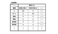
- FIG. 3 is an explanatory diagram of classification information.
- each of the search targets G1 and G2 is one of a plurality of search targets G shown in the water image.
- the number of search target G is one, only the search target G1 is shown in the classification information.
- the types of search target G include people, boats, fishing boats, sailing ships, cargo ships, passenger ships, and the like.
- the classification information indicates the probability that each of these types corresponds to the type of search target G shown in the water image.
- the probability that the type is a person is 90%
- the probability that the type is a boat is 5%
- the probability that the type is a fishing boat is 5%.
- the probability is 0%.
- the search target G2 a plurality of probabilities corresponding to a plurality of types are also shown.
- the search target G1 has the highest probability of being a person
- the search target G2 has the highest probability of being a fishing boat.
- FIG. 4 is an explanatory diagram of the pixel coordinate system.
- the pixel coordinate system is a Cartesian coordinate system composed of an Xp axis and a Yp axis.
- the lower side of the water image is located on the Xp axis of the pixel coordinate system.
- the origin of the pixel coordinate system is located at the center of the lower side of the water image.
- the center of the upper side in the water image is located on the Yp axis of the pixel coordinate system.
- the value of the Yp axis is positive for the center of the upper side in the water image.
- FIG. 5 is an explanatory diagram of area information.
- each of the search targets G1 and G2 is one of the plurality of search targets G shown in the water image.
- the area information indicates the target area of the search target G1 and G2.
- the target area has a rectangular shape.
- each target area of the search target G1, G2, ... Is indicated by the minimum value and the maximum value of the Xp axis and the minimum value and the maximum value of the Yp axis. ..
- the area information can indicate the target area, the information indicating the minimum value and the maximum value of the Xp axis and the minimum value and the maximum value of the Yp axis for each of the search targets G1, G2, ... Not limited to.
- the target detection device 1 adds the target area indicated by the area information and the type and probability indicated by the classification information on the water image of the water image data input to the target detection model 2. Generate additional image data for the image. Specifically, in the additional image, the target area is indicated by a rectangular frame surrounding the search target G, as shown in FIG. Further, regarding the search target G, a label indicating the type corresponding to the highest highest probability among the plurality of probabilities regarding the certainty of classification and the highest probability are arranged in the vicinity of the search target G. In the example of FIG. 2, the type corresponding to the highest probability for the search target G on the left side is a person, and the probability that the search target G on the left side is a person is 70%. Similarly, for the search target G on the right side, the type corresponding to the highest probability is a fishing boat, and the probability that the search target G on the right side is a fishing boat is 80%.
- the target detection device 1 displays an additional image.
- the user of the target detection device 1 confirms the detected search target G in the additional image, and determines, for example, whether or not the flying object F needs to approach the search target G in order to perform a detailed confirmation. ..
- FIG. 6 is a schematic view of the target detection model 2.
- the target detection model 2 is a learning model of machine learning including deep learning, and has a feature extractor 20 and a classification regression device 21.
- Water image data specifically, a plurality of pixel values constituting the water image data are input to the feature extractor 20.
- the feature extractor 20 generates a feature amount map from the water image data by performing a convolution process and a pooling process on the water image data.
- the feature map is a plurality of values represented by a two-dimensional array.
- the feature extractor 20 outputs the extracted feature amount map to the classification regression device 21.
- the classification regression device 21 cuts out the area of the search target G in the feature amount map input from the feature extractor 20.
- the classification regressor 21 calculates the probabilities indicating the certainty of classification for each of the plurality of types based on a plurality of values (a part of the feature amount map) included in the cut out region, and classifies the calculated probabilities indicating the plurality of probabilities. Output information.
- these probabilities are a plurality of probabilities corresponding to a plurality of types such as people, boats and fishing boats.
- a softmax function is used to calculate the probability.
- the classification regression device 21 calculates a probability indicating the certainty of classification for each search target G, and outputs classification information indicating the calculated plurality of probabilities.
- the classification regression device 21 modifies the region of the search target G in order to bring the region of the search target G cut out closer to the actual region.
- the classification regression device 21 returns the correction amount of the region of the search target G.
- the classification regression device 21 outputs region information indicating a target region of a water image corresponding to a region obtained by performing regression. When a plurality of search target G regions are cut out, the classification regression device 21 returns the correction amount of each of the cut out plurality of regions, and obtains a plurality of target regions corresponding to the plurality of regions obtained by performing the regression. Output the indicated area information. When the classification regression device 21 does not detect the region of the search target G, the classification regression device 21 outputs the classification information and the region information indicating that the search target G is not detected.
- Each of the feature extractor 20 and the classification regression device 21 is composed of a convolutional neural network (CNN).
- the CNN has an input layer, a plurality of intermediate layers, and an output layer. There are one or more neurons in each of the input, middle and output layers. The neurons in each layer are unidirectionally connected to the neurons in the previous and next layers with a desired weighting factor and bias.
- a vector having the same number of components as the number of nodes in the input layer is input to the input layer.
- a plurality of pixel values constituting the water image data are input to the input layer of the feature extractor 20.
- a feature map is input to the input layer of the classification regression device 21.
- the data input to each node of the input layer is input to the first intermediate layer.
- the output is calculated using the weighting factor, bias and activation function.
- the calculated value is input to the next intermediate layer.
- the output of the output layer is transmitted to the subsequent layers one after another until the output is obtained.
- the calculation performed in the intermediate layer and the output layer is executed by a processing element such as a CPU (Central Processing Unit), a GPU (Graphic Processing Unit), or a TPU (Tensor processing unit). To.
- a processing element such as a CPU (Central Processing Unit), a GPU (Graphic Processing Unit), or a TPU (Tensor processing unit).
- a convolutional layer, a pooling layer, and the like are included as an intermediate layer or an output layer of the feature extractor 20.
- the intermediate layer or output layer of the classification regression device 21 includes a pooling layer, a fully connected layer (FCL; Fully Connected Layer), and the like.
- ⁇ Generation of target detection model 2> The values of parameters such as the weighting factor and the bias regarding the target detection model 2 are updated based on the training data. This update is the learning of the target detection model 2. By performing the learning, the target detection model 2 is newly generated. For learning, for example, an error backpropagation method is used.
- FIG. 7 is an explanatory diagram of training data.
- the training data includes water image data, type data and area data.
- the type data indicates the type of the search target G shown in the water image of the water image data included in the training data.
- the area data indicates the target area of the search target G reflected in the water image of the water image data included in the training data.
- the water image data included in the training data is the image data of the water image that does not include the horizontal line that is the boundary line between the water surface and the sky.
- the target area is shown in the pixel coordinate system. When the number of search targets G is 2 or more, a plurality of target areas indicated by the area data are associated with each of the plurality of types indicated by the type data.
- a person and a fishing boat are shown as the search target G in the water image of the water image data.
- the type data shows people and fishing boats as types.
- the area data indicates a target area corresponding to a person and a target area corresponding to a fishing boat.
- the target area and the type of the search target G shown in the water image of the water image data are associated with the water image data.
- Target detection model 2 is generated using a large amount of training data.
- the water image data included in the training data is input to the target detection model 2 to acquire the classification information and the area information.
- Each of the acquired classification information and area information is evaluated based on the type indicated by the type data and the area indicated by the area data.
- the value of the parameter of the target detection model 2 is updated. For example, the parameter adjustment amount is calculated using the backpropagation method, and the parameter value is updated based on the calculated adjustment amount.
- FIG. 8 is a block diagram showing a main configuration of the generator 3.
- the generation device 3 is a personal computer, a server, or the like, and generates a new target detection model 2 by learning the target detection model 2, that is, updating the parameter values of the target detection model 2.
- the generation device 3 includes an input unit 30, an output unit 31, an operation unit 32, a storage unit 33, and a control unit 34. These are connected to the internal bus 35.
- Training data is input to the input unit 30 from a device (not shown).
- the control unit 34 acquires training data from the input unit 30.
- the output unit 31 outputs the target detection model 2 according to the instruction of the control unit 34.
- the operation unit 32 has a mouse, a keyboard, a touch panel, and the like, and is operated by the user. When the user performs an operation on the operation unit 32, the operation unit 32 notifies the control unit 34 of information indicating the content of the operation performed by the user.
- the storage unit 33 is a non-volatile memory.
- the target detection model 2 and the computer program P1 are stored in the storage unit 33.
- the control unit 34 has a processing element such as a CPU, GPU, or TPU.
- the processing element of the control unit 34 executes the storage process, the output process, and the model generation process by executing the computer program P1.
- the storage process is a process of storing the training data input to the input unit 30 in the storage unit 33.
- the output process is a process of outputting the target detection model 2 stored in the storage unit 33.
- the model generation process is a process for newly generating the target detection model 2 by updating the value of the parameter of the target detection model 2.
- the number of processing elements included in the control unit 34 may be 2 or more.
- a plurality of processing elements may jointly execute the storage process, the output process, and the model generation process according to the computer program P1.
- the computer program P1 may be provided to the generation device 3 by using a non-temporary storage medium A1 in which the computer program P1 is readablely recorded.
- the storage medium A1 is, for example, a portable memory. Examples of the portable memory include a CD-ROM, a USB (Universal Serial Bus) memory, an SD card, a micro SD card, a compact flash (registered trademark), and the like.
- the processing element of the control unit 34 may read the computer program P1 from the storage medium A1 using a reading device (not shown) and store the read computer program P1 in the storage unit 33. Good.
- the computer program P1 may be provided to the generation device 3 by communication via the communication unit of the generation device 3.
- the processing element of the control unit 34 may acquire the computer program P1 through the communication unit and store the acquired computer program P1 in the storage unit 33.
- control unit 34 executes the storage process.
- the control unit 34 first acquires the training data input to the input unit 30.
- the control unit 34 stores the acquired training data in the storage unit 33, and ends the storage process.
- the control unit 34 executes the output process.
- the control unit 34 reads the target detection model 2 from the storage unit 33.
- the control unit 34 instructs the output unit 31 to output the target detection model 2 read from the storage unit 33 to a device (not shown).
- the control unit 34 ends the output process.
- the target detection model 2 stored in the storage unit 33 of the generation device 3 can be acquired from the generation device 3.
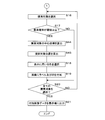
- FIG. 9 is a flowchart showing the procedure of the model generation process.
- the control unit 34 executes the model generation process.
- a certain number is 2 or more.
- the model generation process is executed, the value of the parameter of the target detection model 2 is set.
- the control unit 34 first selects one training data from the plurality of training data stored in the storage unit 33 (step S1). Next, the control unit 34 inputs the water image data selected in step S1 into the target detection model 2 (step S2). Specifically, the control unit 34 inputs a plurality of pixel values constituting the water image data into the target detection model 2. When the water image data is input to the target detection model 2, the control unit 34 calculates in each neuron of the target detection model 2 and outputs the classification information and the area information.
- step S2 the control unit 34 acquires the classification information and the area information output from the target detection model 2 (step S3).
- the control unit 34 evaluates the classification information and the area information acquired in step S3 based on the type data included in the training data selected in step S1 and the type and target area indicated by the area data (step). S4).
- step S4 the control unit 34 evaluates the degree to which the plurality of probabilities indicated by the classification information are appropriate based on the type indicated by the type data. Further, the control unit 34 evaluates the degree to which the area indicated by the area information is appropriate based on the target area indicated by the area data.
- control unit 34 updates the value of the parameter of the target detection model 2 based on the result of the evaluation performed in step S4 (step S5). As a result, a new target detection model 2 is generated.
- step S5 the control unit 34 determines whether or not all the training data stored in the storage unit 33 has been selected (step S6). When the control unit 34 determines that all the training data has not been selected (S6: NO), the control unit 34 executes step S1 again. In step S1 to be executed again, the control unit 34 selects one training data stored in the storage unit 33 and not selected. The control unit 34 keeps updating the parameter values until all the training data are selected.
- control unit 34 determines that all the training data has been selected (S6: YES)
- the control unit 34 deletes all the training data stored in the storage unit 33 (step S7), and ends the model generation process.
- the control unit 34 generates the target detection model 2 based on the plurality of training data.
- the number of times the parameter values are updated using one training data is not limited to one.
- the number of times the parameter values are updated using one training data may be two or more.
- the control unit 34 separately inputs a plurality of water image data included in the plurality of training data into the target detection model 2, and based on the plurality of classification information and the plurality of area information output from the target detection model 2. You may update the value of the parameter.
- the control unit 34 evaluates the degree to which the plurality of probabilities indicated by the plurality of classification information are appropriate.
- the control unit 34 evaluates the degree to which the plurality of regions indicated by the plurality of region information are appropriate based on the plurality of target regions indicated by the plurality of region data.
- the control unit 34 updates the value of the parameter based on the evaluation result by using the backpropagation method.
- a representative value of an appropriate degree for example, an average value of an appropriate degree is used.
- the target detection model 2 may be evaluated using the evaluation data including the water image data, the type data, and the area data.
- the control unit 34 updates the value of the parameter of the target detection model 2 using the plurality of training data, and then inputs the water image data of the evaluation data into the target detection model 2.
- the control unit 34 evaluates the classification information and the area information output from the target detection model 2 by using the type data and the area data included in the evaluation data. In this configuration, if the evaluation does not meet a certain criterion, the control unit 34 may update the parameter values of the target detection model 2 again using the plurality of training data.
- the control unit 34 repeatedly updates the parameter values until the evaluation of the target detection model 2 using the evaluation data satisfies a certain criterion.
- a first method of increasing the water image data for learning there is a method of inverting the left and right of the water image of one water image data.
- a second method of increasing the water image data for learning there is a method of changing at least one of hue, contrast, lightness and saturation in the water image of one water image data.
- a third method of increasing the water image data for learning there is a method of changing a plurality of pixel values constituting one water image data.
- the pixel values of a plurality of pixels are changed for each of red, green, and blue.
- a plurality of pixel values calculated by the product of a plurality of pixel values and a random number are used as a plurality of pixel values constituting new water image data.
- a fourth method of increasing the water image data for learning there is a method of cutting out a part of the water image and returning the scale of the cut water image to the scale of the water image before cutting.
- the plurality of training data used by the generator 3 to generate the target detection model 2 includes training data including water image data generated by the first method, the second method, the third method, or the fourth method. Good.
- FIG. 10 is a block diagram showing a main configuration of the target detection device 1.
- the target detection device 1 detects the search target G based on the water image data.
- the target detection device 1 has four input units 10r, 10f, 11r, 11f, an output unit 12, an input / output unit 13, a reception unit 14, a storage unit 15, a control unit 16, and a display unit 17.
- the four input units 10r, 10f, 11r, 11f, the output unit 12, the input / output unit 13, the reception unit 14, the storage unit 15, and the control unit 16 are connected to the internal bus 18.
- the output unit 12 is further connected to the display 17.
- the flying object F includes a right front camera 40r, a left front camera 40f, a right rear camera 41r, and a left rear camera 41f.
- the input units 10r, 10f, 11r, and 11f of the target detection device 1 are further connected to the right front camera 40r, the left front camera 40f, the right rear camera 41r, and the left rear camera 41f, respectively.
- FIG. 11 is an explanatory diagram of the arrangement of the right front camera 40r, the left front camera 40f, the right rear camera 41r, and the left rear camera 41f.
- the flying object F seen from above is shown.
- the right front camera 40r, the left front camera 40f, the right rear camera 41r, and the left rear camera 41f are located on the right front side, the left front side, the right rear side, and the left rear side in the aircraft F, respectively. It is arranged.
- the right front camera 40r, the left front camera 40f, the right rear camera 41r, and the left rear camera 41f each periodically photograph the water on the right front side, the left front side, the right rear side, and the left rear side of the flying object F.
- each of the right front camera 40r, the left front camera 40f, the right rear camera 41r, and the left rear camera 41f generates water image data of the water image in which the photographed water is captured.
- Each of the right front camera 40r, the left front camera 40f, the right rear camera 41r, and the left rear camera 41f outputs the generated water image data to the input units 10r, 10f, 11r, and 11f each time the water image data is generated. ..
- the control unit 16 acquires water image data from each of the input units 10r, 10f, 11r, and 11f.
- additional image data is generated based on the water image data.
- the output unit 12 outputs the additional image data to the display 17.
- the additional image data includes identification information.
- the identification information indicates the generation source of the water image data used for generating the additional image data.
- the generation source is a right front camera 40r, a left front camera 40f, a right rear camera 41r, or a left rear camera 41f.
- the display 17 displays an additional image of the additional image data.
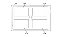
- FIG. 12 is a front view of the display 17. As shown in FIG. 12, the front surface of the display 17 has a rectangular shape.
- the display 17 is provided with four rectangular display screens 50r, 50f, 51r, and 51f on the front surface.
- the display screens 50r and 50f are arranged in the left-right direction, and the display screen 50f is arranged on the left side of the display screen 50r.
- the display screens 51r and 51f are also arranged in the left-right direction, and the display screen 51f is arranged on the left side of the display screen 51r.
- the display screens 50r and 51r are arranged in the vertical direction, and the display screen 51r is arranged below the display screen 50r.
- the display screens 50f and 51f are also arranged in the vertical direction, and the display screen 51f is arranged below the display screen 50f.
- the right front camera 40r, the left front camera 40f, the right rear camera 41r, and the left rear camera 41f correspond to the display screens 50r, 50f, 51r, and 51f, respectively.
- the display 17 adds the input additional image of the input additional image data on the display screens 50r, 50f, 51r, 51f. It is displayed on the display screen corresponding to the generation source indicated by the identification information included in the image data. Therefore, when the additional image data including the identification information indicating the right front camera 40r is input from the output unit 12 to the display unit 17, the display unit 17 displays the additional image of the input additional image data on the display screen 50r. To do.
- Display screens 50r, 50f, 51r, and 50f are arranged on the upper right side, the upper left side, the lower right side, and the lower left side of the arrow, respectively. Therefore, the user can intuitively understand that the display screens 50r, 50f, 51r, and 51f correspond to the right front camera 40r, the left front camera 40f, the right rear camera 41r, and the left rear camera 41f, respectively. it can.
- the target detection device 1 shown in FIG. 10 further has an operation unit (not shown) such as a mouse, a keyboard, or a touch panel.
- the user of the target detection device 1 inputs a value by operating the operation unit.
- the reception unit 14 receives the value input by the user.
- the reception unit 14 notifies the control unit 16 of the accepted value.
- the storage unit 15 is a non-volatile memory.
- the target detection model 2 and the computer program P2 are stored in the storage unit 15.
- the control unit 16 has a processing element such as a CPU, GPU, or TPU.
- the processing element (computer) of the control unit 16 executes the model update process, the data set output process, the four target detection processes, and the threshold value change process by executing the computer program P1.
- the model update process is a process of updating the target detection model 2 stored in the storage unit 15 to the target detection model 2 input to the input / output unit 13.
- the data set includes the water image data input to the target detection model 2 and the classification information and the area information acquired by inputting the water image data into the target detection model 2.
- the data set output process is a process for outputting a data set.
- the target detection process is a process of detecting the search target G based on the water image data and displaying an additional image showing the type of the detected search target G.
- the water image data is input to the target detection model 2 to acquire the classification information and the area information.
- a dataset containing water image data, classification information and area information is generated.
- the generated data set is stored in the storage unit 15.
- Each of the four target detection processes corresponds to the right front camera 40r, the left front camera 40f, the right rear camera 41r, and the left rear camera 41f.
- the search target G is detected based on the water image data input from the corresponding camera in the right front camera 40r, the left front camera 40f, the right rear camera 41r, and the left rear camera 41f. ..
- the control unit 16 determines whether or not to indicate the type using the threshold value.
- the threshold value change process is a process of changing the threshold value used in determining whether or not to indicate the type.
- the threshold value is stored in the storage unit 15.
- the number of processing elements included in the control unit 16 may be 2 or more.
- the plurality of processing elements may jointly execute the model update process, the data set output process, the target detection process, and the threshold value change process according to the computer program P2.
- the computer program P2 may be provided to the target detection device 1 by using a non-temporary storage medium A2 in which the computer program P2 is readablely recorded.
- the storage medium A2 is, for example, a portable memory.
- the processing element of the control unit 16 may read the computer program P2 from the storage medium A2 using a reading device (not shown) and store the read computer program P2 in the storage unit 15. Good.
- the target detection device 1 includes a communication unit that communicates with the external device
- the computer program P2 may be provided to the target detection device 1 by communication via the communication unit of the target detection device 1. In this case, the processing element of the control unit 16 may acquire the computer program P2 through the communication unit and store the acquired computer program P2 in the storage unit 15.
- ⁇ Model update process> For example, when the target detection model 2 is input from the generation device 3 to the input / output unit 13, the control unit 16 executes the model update process. In the model update process, the control unit 16 updates to the target detection model 2 input to the input / output unit 13 stored in the storage unit 15, and ends the model update process.
- ⁇ Data set output processing> For example, when the user performs an operation instructing the output of the data set in the operation unit, the control unit 16 executes the data set output process. In the data set output process, the control unit 16 reads out the data set stored in the storage unit 15. Next, the control unit 16 instructs the input / output unit 13 to output the read data set, and ends the data set output process. The user can generate new training data necessary for retraining the target detection model 2 based on the data set.
- FIG. 13 is a flowchart showing the procedure of the target detection process.
- the target detection process corresponding to the right front camera 40r will be described.
- the control unit 16 executes the target detection process corresponding to the right front camera 40r.
- the control unit 16 acquires water image data from the input unit 10r (step S11).
- the control unit 16 functions as a data acquisition unit.
- the control unit 16 inputs the water image data acquired in step S11 into the target detection model 2 (step S12).
- the control unit 16 inputs a plurality of pixel values constituting the water image data into the target detection model 2.
- the control unit 16 performs calculation in each neuron of the target detection model 2 and outputs classification information and area information.
- the control unit 16 also functions as a data input unit.
- the control unit 16 After executing step S12, the control unit 16 acquires the classification information and the area information output from the target detection model 2 (step S13). Next, the control unit 16 determines whether or not the search target G has been detected based on the classification information and the area information acquired in step S13 (step S14). When the classification information and the area information acquired in step S13 indicate that the search target G is not detected, the control unit 16 determines that the search target G is not detected. If the classification information and the area information acquired in step S13 do not indicate that the search target G is not detected, the control unit 16 determines that the search target G has been detected.
- control unit 16 determines that the search target G has been detected (S14: YES), the data including the water image data input to the target detection model 2 in step S12 and the classification information and area information acquired in step S13.
- the set is stored in the storage unit 15 (step S15).
- the control unit 16 selects one search target G from the plurality of search target Gs indicated by the classification information and the area information acquired in step S13 (step S16).
- the control unit 16 selects one search target G indicated by the classification information and area information.
- the control unit 16 determines whether or not the maximum probability of the search target G selected in step S16 is equal to or greater than the threshold value based on the classification information acquired in step S13 (step). S17).
- the classification information acquired in step S13 is the classification information shown in FIG. 3
- the search target G1 is selected in step S16
- the highest probability is the probability that the type is a person, that is, 90%.
- the search target G2 is selected in step S16
- the highest probability is the probability that the type is a boat, that is, 90%.
- the control unit 16 also functions as a probability determination unit.
- control unit 16 determines that the maximum probability is equal to or higher than the threshold value (S17: YES)
- the control unit 16 selects the type, the probability, and the color used for displaying the target area (step S18).
- the control unit 16 can select a color according to the highest probability, the type showing the highest probability, or the like.
- FIG. 14 is a chart showing the relationship between the highest probability and color.
- step S18 in the configuration in which the control unit 16 selects a color according to the maximum probability, as shown in FIG. 14, a table showing the relationship between the maximum probability and the color is stored in the storage unit 15.
- the highest probability field shows multiple ranges for the highest probability.
- the color field shows the color corresponding to each of the plurality of ranges shown in the highest probability field.
- step S18 the control unit 16 selects a color corresponding to the range to which the highest probability belongs.
- the threshold value is 60%. Therefore, if the maximum probability is less than 60%, step S18 will not be executed. Therefore, in FIG. 14, the color corresponding to the range where the maximum probability is less than 60% is not shown.
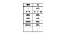
- FIG. 15 is a chart showing the relationship between type and color.
- step S18 in the configuration in which the control unit 16 selects a color according to the type showing the highest probability, as shown in FIG. 15, a table showing the relationship between the type and the color is stored in the storage unit 15. In this table, a type field and a color field are provided. Multiple types are indicated in the type field. The color field shows the color corresponding to each of the plurality of types shown in the type field.
- the control unit 16 selects the color corresponding to the type having the highest probability. In the case where the classification information acquired in step S13 is the classification information shown in FIG. 3, when the search target G1 is selected in step S16, the type corresponding to the highest probability is a person. Therefore, in step S18, the control unit 16 selects the red color corresponding to the person.
- step S18 the control unit 16 displays a label indicating the type corresponding to the highest probability and the highest probability and a frame indicating the target area of the search target G selected in step S16 on the image at the bottom of FIG. Add as shown on the side (step S19).
- the color selected in step S18 is used as the background color of the characters on the label and / or one of the colors of the frame.
- step S19 which is first executed after the execution of the target detection process is started, the control unit 16 adds a label and a frame on the water image of the water image data input to the target detection model 2 in step S12. As a result, additional image data is generated.
- the number of times the control unit 16 executes step S19 may be 2 or more.
- the control unit 16 adds a label and a frame to the additional image of the additional image data generated in the previous step S19. As a result, new additional image data in which a plurality of labels and a plurality of frames are added on the water image is generated.
- step S17 When the control unit 16 determines that the maximum probability is less than the threshold value (S17: NO), or after executing step S19, the control unit 16 selects all the search target Gs indicated by the classification information and the area information acquired in step S13. It is determined whether or not this has been done (step S20). When the control unit 16 determines that all the search target Gs have not been selected (S20: NO), the control unit 16 executes step S16. In step S16 to be executed again, the control unit 16 selects one search target G that is indicated by the classification information and area information acquired in step S13 and is not selected. When the maximum probability of the selected search target G is equal to or greater than the threshold value, a new label and frame are added to the additional image of the additional image data generated in the previous step S19.
- Step S21 the control unit 16 instructs the output unit 12 to output the additional image data generated by executing step S19 to the display unit 17.
- the display 17 displays the additional image of the additional image data input from the output unit 12 on the display screen 50r corresponding to the right front camera 40r.
- the type, probability, and frame shown in the additional image are the contents of the classification information and the area information, that is, the output result of the target detection model 2. Therefore, the display 17 displays the output result of the target detection model 2 by displaying the additional image on the display screen 50r.
- step S21 When the control unit 16 determines that the search target G has not been detected (S14: NO), or after executing step S21, the control unit 16 ends the target detection process. Further, when step S19 is not executed from the start of the target detection process until it is determined that all the search target Gs have been selected in step S20, that is, when the additional image data is not generated. The control unit 16 omits the execution of step S21.
- the control unit 16 may instruct the output unit 12 to output the water image data input to the target detection model 2 in step S12 to the display 17.
- the display 17 displays the water image on the display screen 50r.
- the three target detection processes corresponding to the left front camera 40f, the right rear camera 41r, and the left rear camera 41f are the same as the target detection processes corresponding to the right front camera 40r. Therefore, the description of these target detection processes will be omitted.
- each of the input units 10f, 11r, and 11f is input in the description of the target detection process corresponding to the right front camera 40r.
- Each of the display screens 50f, 51r, and 51f corresponds to the display screen 50r in the description of the target detection process corresponding to the right front camera 40r.
- the control unit 16 acquires four surface image data from the right front camera 40r, the left front camera 40f, the right rear camera 41r, and the left rear camera 41f in the four target detection processes.
- the control unit 16 inputs the acquired four surface image data into the target detection model 2 separately.
- the display 17 corresponds to the camera that outputs the output result of the target detection model 2 and outputs the water image data input to the target detection model 2. Display on the display screen.
- the display 17 is a target detection model 2 that corresponds to the water image data of the right front camera 40r, the left front camera 40f, the right rear camera 41r, and the left rear camera 41f on the display screens 50r, 50f, 51r, and 51f, respectively. Display the output result.
- the user can easily determine the direction of the search target G with respect to the flying object F based on the display screen on which the additional image is displayed. Can be recognized. For example, when the display screen 50r displays the additional image, the user can easily recognize that the search target G shown in the additional image exists in front of the right front of the flying object F.
- FIG. 16 is a flowchart showing the procedure of the threshold value change process.
- the control unit 16 periodically executes the threshold value change process.
- the control unit 16 determines whether or not the reception unit 14 has received the value (step S31).
- the control unit 16 changes the threshold value stored in the storage unit 15 to the value received by the reception unit 14 (step S32).
- the control unit 16 also functions as a change unit.
- the control unit 16 ends the threshold value change process when it is determined that the reception unit 14 is not accepting the value (S31: NO) or after the step S32 is executed.
- the target detection model 2 the relationship between the surface image data and the target area and type of the search target G is learned. Therefore, by inputting the water image data into the target detection model 2, an output result indicating the target area and type of the search target G in the image of the water image data is obtained, and the search target G is accurately detected. Since the display 17 displays an additional image showing the target area and type of the search target G on the water image, the user can easily confirm the position and type of the search target G. Since the type corresponding to the highest probability is displayed in the additional image, it is easier to confirm the type of the search target G.
- the type of search target G whose maximum probability is equal to or greater than the threshold value is displayed, and the type of search target G whose maximum probability is less than the threshold value is not displayed. Therefore, since the number of search target Gs to be confirmed is small, the user can efficiently find the search target G.
- the type, the highest probability, and the target area are displayed using the color corresponding to the highest probability, the user can find the search target G more efficiently. Since the user can freely change the threshold value according to the weather, brightness, and the like around the flying object F, the convenience of the target detection device 1 is high.
- the storage unit 15 of the target detection device 1 may store four target detection models 2.
- each of the four processing elements executes the four target detection models 2.
- four target detection models 2 are used. Therefore, even when one processing element performs the calculation in one target detection model 2, the other processing elements can perform the calculation in the other target detection model 2. In this case, the four target detection processes are efficiently executed.
- the contents of the four target detection models 2 may be common or different from each other. When the four target detection models 2 are different from each other, the learning of the four target detection models 2 is performed separately.
- the display 17 of the target detection device 1 in the first embodiment displays an additional image, and the additional image shows the type and the maximum probability of the search target G.
- the items displayed in the additional image are not limited to the type of search target G and the highest probability.
- the difference between the second embodiment and the first embodiment will be described. Since the other configurations other than the configurations described later are common to the first embodiment, the same reference numerals as those of the first embodiment are assigned to the components common to the first embodiment, and the description thereof is omitted. To do.
- FIG. 17 is a block diagram showing a main configuration of the target detection device 1 according to the second embodiment.
- the flying object F in the second embodiment includes an altimeter 42, a heading indicator 43, and a GPS (in addition to the target detection device 1, the right front camera 40r, the left front camera 40f, the right rear camera 41r, and the left rear camera 41f).
- Global Positioning System The receiver 44 is provided.
- the target detection device 1 according to the second embodiment has three input units 60, 61, 62 in addition to the components included in the target detection device 1 according to the first embodiment.
- the input units 60, 61, 62 are connected to the internal bus 18.
- the inputs 60, 61, and 62 are further connected to the altimeter 42, the heading indicator 43, and the GPS receiver 44, respectively.
- the altimeter 42 periodically measures the altitude, that is, the distance from the water surface to the flying object F.
- the altimeter 42 outputs altitude information indicating the measured altitude to the input unit 60 each time the altitude is measured.
- the control unit 16 acquires altitude information from the input unit 60.
- the altimeter 42 may be configured to measure the altitude based on the absolute pressure of the atmosphere, or a radio wave reflected on the water surface may fly after emitting a vertical radio wave from the flying object F toward the water surface.
- the altitude may be measured based on the time required to reach the body F.
- the heading indicator 43 periodically measures the flight direction, specifically, the angle formed by the north and the nose of the flying object F.
- the flight direction is a clockwise angle with respect to the north. Therefore, when the nose of the aircraft F is facing east, the flight direction is 90 degrees. When the nose of the aircraft F is facing west, the flight direction is 270 degrees.
- the heading indicator 43 is realized by using, for example, a gyroscope. Each time the heading indicator 43 measures the flight direction, it outputs the direction information indicating the measured flight direction to the input unit 61.
- the control unit 16 acquires directional information from the input unit 61.
- the GPS receiver 44 periodically calculates the position of the flying object, which is the position of the flying object F, based on the signals received from the plurality of GPS satellites by the GPS receiver.
- the position of the aircraft is represented by latitude and longitude.
- the GPS receiver outputs the flight body position information indicating the calculated flight body position to the input unit 62.
- ⁇ Target detection process> 18 and 19 are flowcharts showing the procedure of the target detection process.
- the target detection process corresponding to the right front camera 40r will be described.
- the control unit 16 executes the target detection process corresponding to the right front camera 40r when the water image data of the input unit 10r is input from the right front camera 40r.
- a plurality of processes are added to the target detection process according to the first embodiment. Therefore, the description of the target detection process in the first embodiment included in the target detection process in the second embodiment, that is, steps S11 to S21 will be omitted.
- step S15 the control unit 16 acquires altitude information from the input unit 60 (step S41), acquires directional information from the input unit 61 (step S42), and acquires aircraft body position information from the input unit 62. (Step S43).
- the control unit 16 executes step S16 after executing step S43.
- the control unit 16 determines that the maximum probability of the search target G selected in step S16 is equal to or greater than the threshold value (S17: YES)
- the control unit 16 selects the search target G in step S16 based on the area information acquired in step S13.
- the center coordinates of (step S44) are calculated.
- the center coordinates are the coordinates of the pixel coordinate system.
- the center coordinates are the average value of the minimum and maximum values of the Xp axis. It is represented by the average value of the minimum value and the maximum value of the Yp axis.
- the control unit 16 determines the altitude, the flight direction, and the position of the flying object indicated by the altitude information, the directional information, and the flying object position information acquired in steps S41, S42, and S43, and the center coordinates of the search target G calculated in step S44. Based on the above, the search target position, which is the position of the search target G, is calculated (step S45). The search target position is represented by latitude and longitude. The calculation of the search target position will be described later.
- the control unit 16 executes step S18 after executing step S45.
- the area information is the output result of the target detection model 2, and the coordinates of the search target G indicated by the area information are the coordinates on the water image because they are represented by the pixel coordinate system. Therefore, the control unit 16 also functions as a calculation unit.
- step S19 of the target detection process in the second embodiment the control unit 16 selects not only the type corresponding to the highest probability and the highest probability, but also the label indicating the search target position calculated in step S45 and the target position in step S16.
- a frame indicating the target area of the search target G is added.
- the control unit 16 executes step S21, the display 17 displays an additional image on the display screen 50r. In this additional image, not only the type corresponding to the highest probability and the highest probability, but also the position of the search target G is shown.
- the three target detection processes corresponding to the left front camera 40f, the right rear camera 41r, and the left rear camera 41f are the same as the target detection processes corresponding to the right front camera 40r. Therefore, the description of these target detection processes will be omitted.
- each of the input units 10f, 11r, and 11f is input in the description of the target detection process corresponding to the right front camera 40r.
- Each of the display screens 50f, 51r, and 51f corresponds to the display screen 50r in the description of the target detection process corresponding to the right front camera 40r.
- FIG. 20 is an explanatory diagram of the display of the additional image.
- FIG. 20 shows a display screen 50r of the display device 17 when step S21 of the target detection process corresponding to the right front camera 40r is executed.
- An additional image is displayed on the display screen 50r.
- the latitude and longitude are shown in parentheses.
- the value on the left in parentheses indicates the latitude.
- the value on the right in parentheses indicates longitude.
- the processing element of the control unit 16 changes the additional image displayed on the display screen 50r by executing the computer program P2. Execute image change processing.
- This image change process corresponds to the right front camera 40r.
- Object selection is realized by selection using a pointer, tapping on the display screen 50r, or the like.
- the additional image data generated in step S19 of the target detection process corresponding to the right front camera 40r is stored in the storage unit 15.
- the control unit 16 instructs the output unit 12 to output the additional image data generated in step S19 of the previous target detection process to the display unit 17.
- the additional image of the additional image data generated in step S19 of the previous target detection process for example, the additional image shown at the lower side of FIG. 20 is displayed.
- Objects are displayed on the left side and the right side of the additional image on the display screen 50r.
- the control unit 16 ends the image change process after instructing the output unit 12 to output the additional image data.
- control unit 16 When the object on the right side of the display screen 50r is further selected, the control unit 16 again executes the image change process corresponding to the right front camera 40r. In this image change process, the control unit 16 causes the output unit 12 to output the additional image data generated before the additional image data of the additional image displayed on the display screen 50r. As a result, the additional image of the additional image data generated in step S19 of the previous target detection process is displayed on the display screen 50r.
- the control unit 16 executes the image change process corresponding to the right front camera 40r.
- the control unit 16 causes the output unit 12 to output the additional image data generated after the additional image data of the additional image displayed on the display screen 50r.
- the additional image of the additional image data generated in step S19 of the target detection process later is displayed on the display screen 50r.
- the control unit 16 executes the image change process corresponding to the right front camera 40r, whereby the user confirms the additional images of all the additional image data generated by the image change process corresponding to the right front camera 40r. can do.
- the latest additional image and the additional image changed by the image change process may be displayed on the display screen 50r.
- ⁇ Other image change processing> When the user selects a triangular object displayed on each of the display screens 50f, 51r, 51f, the processing element of the control unit 16 displays the display screens 50f, 51r, 51f by executing the computer program P2. Execute the image change process to change the displayed additional image.
- the image change process for changing the additional image displayed on each of the display screens 50f, 51r, and 51f corresponds to the left front camera 40f, the right rear camera 41r, and the left rear camera 41f.
- Each of the three image change processes corresponding to the left front camera 40f, the right rear camera 41r and the left rear camera 41f is executed in the same manner as the image change process corresponding to the right front camera 40r.
- a plurality of processing elements may jointly execute four image change processes according to the computer program P2.
- the control unit 16 calculates the search target position, and the search target position calculated by the control unit 16 is displayed by the display 17. Therefore, when it is necessary for the flight body F to head toward the search target G, the user instructs the operator of the flight body F to quickly reach the search target G based on the search target position calculated by the control unit 16. be able to.
- the target detection device 1 according to the second embodiment similarly exhibits the effect of the target detection device 1 according to the first embodiment.
- the control unit 16 of the target detection device 1 in the first embodiment may execute four image change processes as in the second embodiment.
- FIG. 21 is a first explanatory diagram of numerical values used for calculating the search target position.
- the pixel coordinate system is shown on the upper side of FIG. 21.
- the center coordinates of the search target G in the pixel coordinate system are represented by (Px, Py).
- the value on the Xp axis is shown on the left side in parentheses, and the value on the Yp axis is shown on the right side in parentheses.
- the maximum value of the Xp axis is Wx
- the minimum value of the Xp axis is ⁇ Wx
- the minimum value of the Yp axis is zero
- the maximum value of the Yp axis is Hy.
- Wx and Hy are known numerical values that are set in advance.
- Px and Py are known numerical values calculated in step S45.
- the lower side of FIG. 21 shows the distance coordinate system converted from the pixel coordinate system.
- the distance coordinate system is an orthogonal coordinate system composed of an Xd axis and a Yd axis, and is a coordinate system in which the unit of one scale is meters.
- the Xd axis corresponds to the Xp axis of the pixel coordinate system.
- the Yd axis corresponds to the Yp axis of the pixel coordinate system.
- the center coordinates of the search target G in the distance coordinate system are represented by (Dx, Dy).
- the value on the Xd axis is shown on the left side in parentheses, and the value on the Yd axis is shown on the right side in parentheses.
- Each of Dx and Dy is calculated based on known numerical values.
- FIG. 22 is a second explanatory diagram of numerical values used for calculating the search target position.
- FIG. 22 shows the flying object F and the search target G as seen from the front side.
- Hf is the altitude of the flying object F, which is a known value measured by the altimeter 42.
- L is the distance between the flying object F and the search target G in the left-right direction of the flying object F, and is calculated based on a known numerical value.
- ⁇ t is an angle that can be photographed by the right front camera 40r with respect to the vertical direction of the flying object F, and is a known value.
- ⁇ g is an angle from the upper side to the search target position in the water image of the right front camera 40r with respect to the vertical direction of the flying object F, and is calculated based on a known value.
- FIG. 23 is a third explanatory diagram of numerical values used for calculating the search target position.
- FIG. 23 shows the flying object F and the search target G as viewed from above.
- ⁇ f is the flight direction and is a known value measured by the heading indicator 43.
- the direction on the left side of the water image coincides with the flight direction.
- ⁇ t is an angle formed by two directions corresponding to the left side and the right side in the water image, and is a known value.
- ⁇ c is an angle formed by the direction on the left side and the axial direction of the right front camera 40r in the water image, and is a known value.
- the axial direction of the right front camera 40r is the axial direction of the lens of the right front camera 40r.
- ⁇ g is an angle from the axial direction of the right front camera 40r to the search target position, and is calculated based on a known value.
- ⁇ f, ⁇ t, ⁇ c and ⁇ g are angles viewed from above the flying object F.
- the angle ⁇ p per pixel on the Yp axis is calculated by the following formula using Hy and ⁇ t.
- ⁇ g ⁇ t- ( ⁇ p ⁇ Py) " ⁇ " Represents a product.
- Dy shown on the lower side of FIG. 21 is calculated by the following formula using Hf and ⁇ g.
- Dy Hf / tan ( ⁇ g)
- Dx shown on the lower side of FIG. 21 is calculated by the following formula using Dy, Wx and Px.
- Dx Dy / (Wx ⁇ Px)
- ⁇ g shown in FIG. 23 is calculated by the following formula using Dx and Dy.
- ⁇ g arctan (Dx / Dy)
- L shown in FIG. 22 is calculated by the following formula using Dy and ⁇ g.
- L Dy / cos ( ⁇ g)
- the angle ⁇ n from the north to the search target G is expressed by the following equation using ⁇ f, ⁇ c and ⁇ g.
- ⁇ n ⁇ f + ⁇ c + ⁇ g
- the latitude and longitude of the aircraft position are described as Fa and Fb, respectively.
- Fa and Fb are known values calculated by the GPS receiver 44.
- the radius of the earth is described as Re.
- Re is also a known value.
- the latitude and longitude of the search target position are described as Ga and Gb, respectively.
- Ga is calculated by the following formula using Fa, L, ⁇ n and Re.
- Ga Fa + (L ⁇ sin ( ⁇ n) ⁇ 360 / Re)
- Gb is calculated by the following formula using Fa, Fb, L, ⁇ and Re.
- Gb Fb + ((L ⁇ cos ( ⁇ n) / cos (Fa)) ⁇ (360 / Re))
- step S45 of the target detection process corresponding to the right front camera 40r the control unit 16 uses the altitude, the flight direction, the position of the flying object, the center coordinates of the search target G, and the plurality of equations described above to obtain the search target position. That is, Ga and Gb can be calculated.
- step S45 of the target detection process corresponding to each of the left front camera 40f, the right rear camera 41r and the left rear camera 41f the control unit 16 performs the search performed in step S45 of the target detection process corresponding to the right front camera 40r. The same calculation as the calculation of the target position is performed.
- the notification of the type of the search target G to the user is realized by displaying an additional image indicating the type on the display device 17.
- the notification to the user of the type of the search target G is not limited to the notification by display.
- the differences between the third embodiment and the first embodiment will be described. Since the other configurations other than the configurations described later are common to the first embodiment, the same reference numerals as those of the first embodiment are assigned to the components common to the first embodiment, and the description thereof is omitted. To do.
- FIG. 24 is a block diagram showing a main configuration of the target detection device 1 according to the third embodiment.
- the target detection device 1 according to the third embodiment has an output unit 63 and a voice notification unit 64 in addition to the components included in the target detection device 1 according to the first embodiment.
- the output unit 63 is separately connected to the internal bus 18 and the voice notification unit 64.
- the output unit 63 outputs voice data to the voice notification unit 64 according to the instruction of the control unit 16.
- the audio data indicates the type, maximum probability, and position of the search target G displayed in the additional image, and also includes the display screen on which the additional image is displayed, the source of the water image data, and the shooting direction of the source. At least one of is shown.
- the display screen is one of the display screens 50r, 50f, 51r, and 51f.
- the generator is one of the right front camera 40r, the left front camera 40f, the right rear camera 41r, and the left rear camera 41f.
- the voice notification unit 64 is, for example, a speaker, and when voice data is input from the output unit 63, the voice notification unit 64 notifies the content indicated by the input voice data by voice.
- FIG. 25 is a flowchart showing the procedure of the target detection process.
- the control unit 16 executes the target detection process corresponding to the right front camera 40r when the water image data of the input unit 10r is input from the right front camera 40r.
- the target detection process according to the third embodiment a plurality of processes are added to the target detection process according to the first embodiment. Therefore, the description of the target detection process in the first embodiment included in the target detection process in the third embodiment, that is, steps S11 to S21 will be omitted.
- the control unit 16 generates voice data after executing step S21 (step S51).
- the audio data indicates the type, maximum probability, and position of the search target G displayed on the additional image, and is included in the display screen on which the additional image is displayed, the source of the water image data, and the shooting direction of the generation source. At least one is shown. Examples of the position include the center, upper side, lower side, left side and right side of the additional image.
- the target detection process corresponding to the right front camera 40r, the display screen, the generation source, and the shooting direction indicated by the audio data are the display screen 50r, the right front camera 40r, and the right front, respectively.
- control unit 16 instructs the output unit 63 to output the voice data generated in step S51 to the voice notification unit 64 (step S52).
- voice notification unit 64 notifies the content indicated by the voice data by voice.
- control unit 16 determines that the search target G has not been detected (S14: NO), or after executing step S43, the control unit 16 ends the target detection process.
- step S19 is not executed from the start of the target detection process until it is determined that all the search targets G have been selected in step S20, that is, if the additional image data is not generated, the control unit In step 16, execution of steps S21, S51, and S52 is omitted.
- the three target detection processes corresponding to the left front camera 40f, the right rear camera 41r, and the left rear camera 41f are the same as the target detection processes corresponding to the right front camera 40r. Therefore, the description of these target detection processes will be omitted.
- each of the input units 10f, 11r, and 11f is input in the description of the target detection process corresponding to the right front camera 40r.
- Each of the display screens 50f, 51r, and 51f corresponds to the display screen 50r in the description of the target detection process corresponding to the right front camera 40r.
- the voice notification unit 64 notifies the type corresponding to the highest probability in the classification information, and displays the display screen corresponding to the highest probability, the camera corresponding to this display screen, and the camera. At least one of the directions taken by the camera is notified by voice.
- the target detection device 1 according to the third embodiment not only the additional image showing the target area and type of the search target G is displayed, but also the type of the search target G and the information related to the search target G are voice notification units. Notified by 64. Therefore, the user can find the search target more reliably.
- the target detection device 1 according to the third embodiment similarly exhibits the effect of the target detection device 1 according to the first embodiment.
- the target detection device 1 in the second embodiment has an output unit 63 and a voice notification unit 64 as in the third embodiment, and may notify the type of the search target G, the maximum probability, and the like by voice. ..
- the threshold value is changed to the value received by the reception unit 14.
- the configuration for changing the threshold value is not limited to the configuration for accepting a value.
- the differences between the fourth embodiment and the first embodiment will be described. Since the other configurations other than the configurations described later are common to the first embodiment, the same reference numerals as those of the first embodiment are assigned to the components common to the first embodiment, and the description thereof is omitted. To do.
- FIG. 26 is a block diagram showing a main configuration of the target detection device 1 according to the fourth embodiment.
- the flying object F in the fourth embodiment includes a weather radar 45 in addition to the target detection device 1, the right front camera 40r, the left front camera 40f, the right rear camera 41r, and the left rear camera 41f.
- the target detection device 1 in the fourth embodiment has other components other than the reception unit 14 among the components of the target detection device 1 in the first embodiment.
- the target detection device 1 in the fourth embodiment further has an input unit 65.
- the input unit 65 is separately connected to the internal bus 18 and the weather radar 45.
- the weather radar 45 periodically detects the weather around the aircraft F. For example, the weather radar 45 emits electromagnetic waves and detects the weather based on the frequency of the electromagnetic waves reflected by the object. Each time the weather radar 45 detects the weather around the aircraft F, the weather radar 45 outputs the weather information indicating the detected weather to the input unit 65.
- the control unit 16 acquires weather information from the input unit 65.
- the weather includes sunny, cloudy, rainy and snowy.
- FIG. 27 is a flowchart showing the procedure of the threshold value change process.
- the control unit 16 periodically executes the threshold value change process as in the first embodiment.
- the control unit 16 first acquires weather information from the input unit 65 (step S61).
- the control unit 16 also functions as an information acquisition unit.
- the control unit 16 changes the threshold value based on the weather information acquired in step S61 (step S62).
- the control unit 16 changes the threshold value stored in the storage unit 15, for example, by using a table showing the relationship between the weather and the candidate value of the threshold value.
- FIG. 28 is a chart showing the relationship between the weather and the candidate value of the threshold value.
- a table showing the relationship between the weather and the candidate value of the threshold value is stored in the storage unit 15.
- a weather field and a candidate value field are provided. Multiple weathers are shown in the weather field.
- the weather is shown as sunny, cloudy, rainy and snowy.
- the candidate value field the candidate value of the threshold value corresponding to each of the plurality of weathers shown in the weather field is shown.
- the candidate values of the threshold values corresponding to sunny, cloudy, rain and snow are 80%, 70%, 60% and 60%, respectively.
- step S62 of the threshold value change process the control unit 16 changes the threshold value to a candidate value corresponding to the weather indicated by the weather information acquired in step S61.
- the control unit 16 changes the threshold value to a candidate value corresponding to sunny, that is, 80%.
- the control unit 16 ends the threshold value change process.
- the target detection device 1 according to the fourth embodiment since the threshold value is changed according to the weather around the flying object F, the target area and type of the search target G are appropriately shown in the additional image.
- the target detection device 1 in the fourth embodiment has other effects other than the effect obtained by changing the threshold value to the value received by the reception unit 14 among the effects performed by the target detection device 1 in the first embodiment. Play in the same way.
- the target detection device 1 in the fourth embodiment may further have a receiving unit (not shown) that receives the weather and the value from the user. For example, when the reception unit receives the weather and the value, the control unit 16 changes the candidate value of the weather threshold value received by the reception unit to the value received by the reception unit.
- the target detection device 1 may have a wireless communication unit that communicates wirelessly.
- the control unit 16 of the target detection device 1 may acquire the weather information from the wireless communication unit instead of the weather radar 45.
- a weather detection unit that detects the weather based on the detection results of a rain sensor that detects rainfall and a brightness sensor that detects the brightness around the air vehicle F is provided on the air vehicle F instead of the weather radar 45. It may have been.
- the weather detection unit periodically outputs the weather information indicating the detected weather to the input unit 65.
- the control unit 16 may change the threshold value according to the weather information indicating the weather around the flying object F, as in the fourth embodiment.
- the threshold value is changed to the value received by the reception unit 14, and in the fourth embodiment, the threshold value is changed according to the weather around the flying object F.
- the configuration for changing the threshold value is not limited to the configuration for changing the value received by the reception unit 14 or the configuration for changing the threshold value according to the weather around the flying object F.
- the differences between the fifth embodiment and the first embodiment will be described. Since the other configurations other than the configurations described later are common to the first embodiment, the same reference numerals as those of the first embodiment are assigned to the components common to the first embodiment, and the description thereof is omitted. To do.
- FIG. 29 is a flowchart showing the procedure of the target detection process according to the fifth embodiment.
- the control unit 16 executes the target detection process corresponding to the right front camera 40r when the water image data of the input unit 10r is input from the right front camera 40r.
- the target detection process according to the fifth embodiment one process is added to the target detection process according to the first embodiment. Therefore, the description of the target detection process in the first embodiment included in the target detection process in the fourth embodiment, that is, steps S11 to S21 will be omitted.
- control unit 16 shown in FIG. 10 sets the threshold value stored in the storage unit 15 to the highest probability among the plurality of probabilities related to the search target G selected in step S16.
- the value is changed according to (step S71).
- the control unit 16 changes the threshold value stored in the storage unit 15, for example, by using a table showing the relationship between the type and the candidate value of the threshold value.
- FIG. 30 is a chart showing the relationship between the type and the candidate value of the threshold value.
- a table showing the relationship between the type and the candidate value of the threshold value is stored in the storage unit 15.
- a type field and a candidate value field are provided. Multiple types are indicated in the type field.
- people, boats, fishing boats, sailing boats, and the like are shown as types.
- the candidate value field the candidate values of the threshold values corresponding to each of the plurality of types shown in the type field are shown.
- the control unit 16 changes the threshold value to a candidate value corresponding to the type of the highest probability.
- the classification information acquired in step S13 is the classification information shown in FIG.
- step S71 the control unit 16 changes the threshold value to a candidate value corresponding to a person.
- the candidate value of the threshold value corresponding to the person is 60%.
- step S17 the control unit 16 determines whether or not the maximum probability is equal to or greater than the threshold value changed in step S71. When the maximum probability is equal to or greater than the threshold value, a label and a frame are added to the image in step S19, and an additional image is generated.
- the three target detection processes corresponding to the left front camera 40f, the right rear camera 41r, and the left rear camera 41f are the same as the target detection processes corresponding to the right front camera 40r. Therefore, the description of these target detection processes will be omitted.
- each of the input units 10f, 11r, and 11f is input in the description of the target detection process corresponding to the right front camera 40r.
- Each of the display screens 50f, 51r, and 51f corresponds to the display screen 50r in the description of the target detection process corresponding to the right front camera 40r.
- the search target G when the type with the highest probability for one search target G is a type with a low threshold candidate value, the search target G is emphasized by the label and the frame in the additional image. Probability is high.
- the candidate value of the threshold value corresponding to a person is low, and the candidate value of the threshold value corresponding to a cargo ship and a passenger ship is high. Therefore, the type of highly important search target G corresponding to the highest probability, for example, the search target G that is likely to require rescue, is likely to be highlighted by the label and frame. As a result, the search target G is more reliably discovered by the user.
- the target detection device 1 in the fifth embodiment has other effects other than the effect obtained by changing the threshold value to the value received by the reception unit 14 among the effects performed by the target detection device 1 in the first embodiment. Play in the same way.
- the target detection device 1 according to the fifth embodiment may further have a receiving unit (not shown) that receives a type and a value from the user. For example, when the reception unit accepts a type and a value, the control unit 16 changes the candidate value of the threshold value of the type accepted by the reception unit to the value accepted by the reception unit. Further, in the target detection device 1 according to the fifth embodiment, the control unit 16 does not execute the threshold value change process. Further, in the target detection device 1 in the second and third embodiments, the control unit 16 may change the threshold value according to the type corresponding to the highest probability, as in the fifth embodiment.
- the display 17 mainly displays the additional image.
- the display 17 may be configured to display both a water image and an additional image.
- the differences between the sixth embodiment and the first embodiment will be described. Since the other configurations other than the configurations described later are common to the first embodiment, the same reference numerals as those of the first embodiment are assigned to the components common to the first embodiment, and the description thereof is omitted. To do.
- FIG. 31 is a front view of the display 17 according to the sixth embodiment.
- the display 17 according to the sixth embodiment is provided with four rectangular display screens 50r, 50f, 51r, and 51f, as in the first embodiment.
- the display 17 according to the sixth embodiment is further provided with four rectangular display screens 70r, 70f, 71r, and 71f.
- the display screens 50r, 50f, 51r, 51f, 70r, 70f, 71r, and 71f are arranged in a grid pattern.
- the display screens 50f, 70f, 50r, and 70r are arranged in this order from the left side.
- the display screens 51f, 71f, 51r, 71r are arranged in this order from the left side.
- each of the display screens 50r, 50f, 51r, and 51f corresponds to the right front camera 40r, the left front camera 40f, the right rear camera 41r, and the left rear camera 41f, and displays additional images. ..
- Each of the display screens 70r, 70f, 71r, and 71f corresponds to the right front camera 40r, the left front camera 40f, the right rear camera 41r, and the left rear camera 41f, and displays a water image.
- the additional image data includes identification information indicating the generation source of the water image data used for generating the additional image data.
- the water image data also includes the identification information indicating the generation source.
- the generation source is a right front camera 40r, a left front camera 40f, a right rear camera 41r, or a left rear camera 41f.
- the display 17 When the additional image data is input to the display 17 from the output unit 12, the display 17 adds the input additional image of the input additional image data on the display screens 50r, 50f, 51r, 51f. It is displayed on the display screen corresponding to the generation source indicated by the identification information included in the image data.
- the display 17 displays the water image of the input water image data on the input water on the display screens 70r, 70f, 71r, 71f. It is displayed on the display screen corresponding to the generation source indicated by the identification information included in the image data.
- Display screens 50r, 50f, 51r, and 50f are arranged on the upper right side, the upper left side, the lower right side, and the lower left side of the arrow, respectively. Therefore, the user can intuitively understand that the display screens 50r, 50f, 51r, and 50f correspond to the right front camera 40r, the left front camera 40f, the right rear camera 41r, and the left rear camera 41f, respectively. it can. Further, display screens 70r, 70f, 71r, and 70f are arranged on the upper right side, the upper left side, the lower right side, and the lower left side of the arrow, respectively. Therefore, the user can intuitively understand that the display screens 70r, 70f, 71r, and 71f correspond to the right front camera 40r, the left front camera 40f, the right rear camera 41r, and the left rear camera 41f, respectively. it can.
- the processing element of the control unit 16 shown in FIG. 10 further executes four image display processes for displaying a water image by executing the computer program P2.
- Each of the four image display processes corresponds to the right front camera 40r, the left front camera 40f, the right rear camera 41r, and the left rear camera 41f.
- the water image of the water image data input from the corresponding camera among the right front camera 40r, the left front camera 40f, the right rear camera 41r and the left rear camera 41f is displayed on the display 17.
- the control unit 16 has a plurality of processing elements, the plurality of processing elements may jointly execute the image display processing according to the computer program P2.
- FIG. 32 is a flowchart showing the procedure of the image display processing.
- the control unit 16 executes an image display process corresponding to the right front camera 40r when the water image data is input from the right front camera 40r to the input unit 10r.
- the control unit 16 acquires water image data from the input unit 10r (step S81).
- the control unit 16 instructs the output unit 12 to output the seaplane image data acquired in step S81 to the display 17 (step S82).
- the display 17 displays the water image of the water image data input from the output unit 12 on the display screen 70r corresponding to the right front camera 40r.
- the control unit 16 ends the image display process.
- the three image display processes corresponding to the left front camera 40f, the right rear camera 41r, and the left rear camera 41f are the same as the image display processes corresponding to the right front camera 40r. Therefore, the description of these image display processes will be omitted.
- each of the input units 10f, 11r, and 11f is input in the description of the image display process corresponding to the right front camera 40r.
- Each of the display screens 70f, 71r, and 71f corresponds to the display screen 70r in the description of the image display process corresponding to the right front camera 40r.
- ⁇ Target detection process> The right front camera 40r photographs the water surface at short time intervals and outputs the water surface image data. Therefore, the control unit 16 outputs the water image data to the input unit 10r from the start of the execution of the target detection process corresponding to the right front camera 40r to the end of the target detection process. Will be done. In this configuration, when the right front camera 40r outputs the water image data to the input unit 10r after the target detection process corresponding to the right front camera 40r is completed, the control unit 16 is the target corresponding to the right front camera 40r. Execute the detection process again.
- the time required for the image display processing corresponding to the right front camera 40r is sufficiently shorter than the time required for the target detection processing corresponding to the right front camera 40r. Therefore, every time the right front camera 40r outputs the water image data to the input unit 10r, the image display process is executed and the water image is displayed on the display screen 70r. On the other hand, additional image data is generated in the target detection process. Therefore, the time interval for updating the water image on the display screen 70r is shorter than the time interval for updating the additional image on the display screen 50r.
- the operations of the left front camera 40f, the right rear camera 41r, and the left rear camera 41f are the same as those of the right front camera 40r.
- the three image display processes corresponding to the left front camera 40f, the right rear camera 41r, and the left rear camera 41f are executed in the same manner as the image display processing corresponding to the right front camera 40r. Further, the execution of the three target detection processes corresponding to the left front camera 40f, the right rear camera 41r and the left rear camera 41f is started under the same conditions as the target detection process corresponding to the right front camera 40r. Therefore, the time interval for updating the water image on each of the display screens 70f, 71r, and 71f is shorter than the time interval for updating the additional image on the display screens 50f, 51r, and 51f.
- the water image is displayed in real time on the display screens 70r, 70f, 71r, 71f. Further, each time the additional image data is generated, the additional image displayed on the display screens 50r, 50f, 51r, 51f is updated. Therefore, effective display is realized.
- the target detection device 1 according to the sixth embodiment similarly exhibits the effect of the target detection device 1 according to the first embodiment.
- the display 17 may display both the water image and the additional image as in the sixth embodiment.
- the water image data of the water image in which a person exists is described as the water image data of a person.
- FIG. 33 is an explanatory diagram of the generation of water image data for learning in the seventh embodiment.
- the storage unit 33 of the generation device 3 shown in FIG. 8 contains a generation model 80 that generates water image data of a person and an identification model that identifies the authenticity of the input water image data of the person. 81 is stored.
- True means that the input human water image data is real human water image data not generated by the generative model 80.
- False means that the input water image data is the water image data of a fake person generated by the generative model 80.
- Each of the generation model 80 and the discriminative model 81 is a learning model composed of a neural network, and has an input layer, an intermediate layer, and an output layer as in the target detection model 2.
- the calculations performed in the intermediate layer and the output layer are performed by a processing element such as a CPU, GPU or TPU.
- the generative model 80 and the discriminative model 81 constitute so-called GANs (Generative Adversarial Networks), and the generative model 80 and the discriminative model 81 are trained in the GANs.
- GANs Generic Adversarial Networks
- the water image data of a person is acquired from the generative model 80.
- a one-dimensional noise vector is input to the generative model 80.
- the noise vector corresponds to predetermined data.
- Each value of the noise vector is a value in the range of -1 to +1 and is set at random.
- the generation model 80 When the noise vector is input to the generation model 80, the generation model 80 generates the water image data of the person and outputs the water image data of the generated person.
- Water image data of a person is also input to the identification model 81.
- a plurality of pixel values constituting the water image data are input to the generation model 80.
- the identification model 81 identifies the authenticity of the input water image data and outputs the identification result. Therefore, the discriminative model 81 outputs true when the input water image data is real person water image data, and false when the input water image data is fake person water image data. Output.
- the processing element of the control unit 34 executes a computer program P1 to perform a second storage process for storing real human water image data not generated by the generation model 80, and a generation model 80. And the learning process for learning the discriminative model 81.
- the control unit 34 executes a second storage process when a plurality of water image data in which a person exists in the water image is input to the input unit 30.
- the control unit 34 first acquires a plurality of water image data input to the input unit 30 as water image data of a real person.
- the control unit 34 stores the acquired plurality of water image data in the storage unit 33, and ends the storage process.
- the control unit 34 executes the learning process.
- the control unit 34 first learns the discriminative model 81 using a plurality of water image data (genuine) acquired in the second storage process. Specifically, the control unit 34 inputs the water image data of the person acquired in the second storage process into the identification model 81. As a result, the discriminative model 81 outputs the discriminative result.
- the control unit 34 updates the value of the parameter of the identification model 81 so that the identification result output from the identification model 81 becomes true.
- the value of the parameter of the discriminative model 81 is repeatedly updated using the plurality of water image data acquired in the second storage process.
- the control unit 34 learns the discriminative model 81 using the water image data (fake) of the person output from the generative model 80. In this learning, the control unit 34 inputs a noise vector to the generative model 80. As a result, the generative model 80 outputs human water image data. Next, the control unit 34 inputs the water image data of the person output from the generation model 80 into the identification model 81, and acquires the identification result output by the identification model 81. Based on the identification result output from the identification model 81, the control unit 34 updates the value of the parameter of the identification model 81 so that the identification result becomes false.
- the generation model 80 When the generation model 80 generates a plurality of water image data, the value of the parameter of the discriminative model 81 is repeatedly updated by using the plurality of water image data generated by the generation model 80. While the discriminative model 81 is being trained using the water image data output from the generative model 80, the parameter values of the generative model 80 are fixed.
- the control unit 34 again inputs the noise vector into the generation model 80, inputs the water image data of the person output from the generation model 80 into the identification model 81, and acquires the identification result output by the identification model 81. To do. Based on the identification result output from the identification model 81, the control unit 34 updates the value of the parameter of the generation model 80 so that the identification result becomes true.
- the value of the parameter of the generation model 80 is repeatedly updated based on each of the plurality of identification results corresponding to the plurality of noise vectors. In this way, the generative model 80 is trained. While the generative model 80 is being trained, the values of the parameters of the discriminative model 81 are fixed. As a result, the generative model 80 will generate human water image data that is almost the same as the real human water image data.
- the learning of the generative model 80 is performed using the discriminative model 81, and the learning of the discriminative model 81 is performed using the plurality of water image data acquired in the second storage process. Therefore, the learning of the generative model 80 is performed using the plurality of water image data acquired in the second storage process.
- the learning of the generative model 80 performed using the discriminative model 81 corresponds to the learning performed using the plurality of water image data acquired in the second storage process.
- the learning of the generative model 80 and the learning of the discriminative model 81 using the water image data of the person output from the generative model 80 are alternately repeated. After a lot of learning, the generative model 80 comes to generate water image data of a high quality person.
- the control unit 34 acquires training data including the water image data of the person output by the generation model 80, and generates the target detection model 2 using the acquired training data.
- the storage unit 15 of the target detection device 1 corresponds to the right front camera 40r, the left front camera 40f, the right rear camera 41r, and the left rear camera 41f.
- One target detection model 2 may be stored.
- the four generation models 80 and the four identification models 81 are stored in the storage unit 33 of the generation device 3.
- the number of combinations of the generative model 80 and the discriminative model 81 is four. Each of the four combinations corresponds to the water image data of a person photographed by the right front camera 40r, the left front camera 40f, the right rear camera 41r, and the left rear camera 41f.
- each of the four generative models 80 generates water image data of a person as photographed by the right front camera 40r, the left front camera 40f, the right rear camera 41r, and the left rear camera 41f.
- the predetermined data to be input to the generation model 80 is not limited to the noise vector, and may be, for example, image data of an image showing water. Further, data including a noise vector and other data may be input to the generation model 80 as predetermined data.
- the generator 3 in the second to sixth embodiments may be configured in the same manner as in the seventh embodiment.
- the processing element for learning the generation model 80 and the identification model 81 is not limited to the processing element of the control unit 34 included in the generation device 3, and a processing element different from the processing element of the control unit 34 may be used.
- the right front camera 40r, the left front camera 40f, the right rear camera 41r and the left rear camera 41f may capture a water image including a horizon.
- the search target G does not exist above (above) the horizon.
- the surface image data is input to the target detection model 2
- FIG. 34 is an explanatory diagram of preventing the display of the label and frame of the search target G that was erroneously detected.
- FIG. 34 shows an additional image in which a label and a frame are added to the water image.
- the control unit 16 of the target detection device 1 determines that the maximum probability of the search target G selected in step S16 is equal to or greater than the threshold value, for example, based on a plurality of pixel values of the water image data. Detect the horizon of the water image.
- the control unit 16 displays the water image.
- Step S20 is executed without adding a label and a frame to the selected search target G. Therefore, in the additional image, the label and frame of the search target G whose distance from the horizon is equal to or greater than the set distance are not shown.
- FIG. 34 it is assumed that the cloud surrounded by the broken line frame is erroneously detected as the search target G.
- the distance between the search target G and the horizon is equal to or greater than the set distance, the label and frame are not shown in the additional image. Even if it is an object on the water like the fishing boat shown in FIG. 34, the object may appear on the upper side of the horizontal plane. A set distance is provided so that the detection of this object does not result in an erroneous detection. Further, instead of adding a label and a frame, a probability lower than the maximum probability may be indicated on the label.
- control unit 16 when the selected search target G appears above the horizon, the control unit 16 reduces the probability indicated on the label from the highest probability according to the distance between the search target G and the horizon. The greater the distance between the search target G and the horizon, the greater the reduction.
- the size of the search target G may be detected.
- the control unit 16 of the target detection device 1 calculates the size of the search target G when it is determined that the maximum probability of the search target G selected in step S16 is equal to or greater than the threshold value.
- the control unit 16 does not add the label and frame of the selected search target G to the water image.
- Step S20 is executed. Therefore, the additional image does not show the label and frame of the search target G having an inappropriate size.
- the type of the search target G is a person and the size (total length) of the search target G is 20 m, it is considered that there is no person with a height of 20 m.
- the G label and frame are not shown.
- a probability lower than the maximum probability may be indicated on the label.
- the control unit 16 labels according to the size of the search target G such as height or height.
- the probability shown in is reduced from the highest probability. This reduction width increases as the difference between the size of the search target G and the predetermined size, that is, the larger the deviation amount.
- the predetermined size depends on the type of highest probability selected in step S16.
- the type data included in the training data may indicate a type other than the type of the search target G, for example, driftwood.
- the target detection model 2 learned from this training data determines the probability of corresponding to a plurality of types of the search target G and each type outside the search target G as the type of the object displayed on the water screen as the classification information. Shown.
- examples of the object include a search target G and an object other than the search target G.
- the display 17 does not display the search target G.
- the visible light region, the infrared region, and the like can be mentioned as the wavelength regions of the light received by the right front camera 40r, the left front camera 40f, the right rear camera 41r, and the left rear camera 41f.
- the flying object F flies in the daytime, the flying object F is equipped with a right front camera 40r, a left front camera 40f, a right rear camera 41r and a left rear camera 41f whose wavelength region is a visible light region.
- the target detection model 2 for daytime is used, which is learned by using the training data including the water image data on the water taken by the camera whose wavelength region is the visible light region.
- the flying object F When the flying object F flies at night, the flying object F is equipped with a right front camera 40r, a left front camera 40f, a right rear camera 41r and a left rear camera 41f whose wavelength region is an infrared region.
- the flying object F When the flying object F flies at night, the flying object F is equipped with a right front camera 40r, a left front camera 40f, a right rear camera 41r, and a left rear camera 41f whose wavelength region is an infrared region.
- the target detection model 2 for nighttime is used, which is learned by using the training data including the water image data on the water taken by the camera whose wavelength region is the infrared region.
- the flying object F When the flying object F flies in the daytime and at night, the flying object F is in addition to the right front camera 40r, the left front camera 40f, the right rear camera 41r and the left rear camera 41f whose wavelength region is the visible light region.
- the right front camera 40r, the left front camera 40f, the right rear camera 41r, and the left rear camera 41f, whose wavelength region is the infrared region, are provided.
- the flying object F is flying in the daytime, in the four target detection processes, it is acquired from the right front camera 40r, the left front camera 40f, the right rear camera 41r and the left rear camera 41f whose wavelength region is the visible light region.
- the water image data is input to the target detection model 2 for daytime.
- the right front camera 40r, the left front camera 40f, the right rear camera 41r and the left rear camera 41f whose wavelength region is the infrared region
- the water image data obtained from is input to the target detection model 2 for nighttime.
- Switching between the right front camera 40r, the left front camera 40f, the right rear camera 41r and the left rear camera 41f, and the switching of the target detection model 2 are the output results of the sensor that detects the brightness around the flying object F, or , It is performed based on the time indicated by the clock unit.
- the display screens 50r, 50f, 51r, and 51f may not be arranged in a grid pattern in front of the display device 17.
- the display screens 50r, 50f, 51r, 51f may be arranged in the vertical direction or the horizontal direction.
- the display screens 50r, 50f, 51r, 51f, 70r, 70f, 71r, 71f may not be arranged in a grid pattern in front of the display 17.
- the display screens 50r, 50f, 51r, 51f, 70r, 70f, 71r, 71f may be arranged in the vertical direction or the horizontal direction.
- the display 17 does not have to be one device provided with the display screens 50r, 50f, 51r, 51f.
- the display 17 may have, for example, a configuration having four display units provided with display screens 50r, 50f, 51r, and 51f, respectively. In this case, the four display units are arranged separately.
- the display 17 does not have to be one device provided with the display screens 50r, 50f, 51r, 51f, 70r, 70f, 71r, 71f.
- the display 17 may have, for example, a configuration having eight display units provided with display screens 50r, 50f, 51r, 51f, 70r, 70f, 71r, and 71f, respectively. In this case, the eight display units are arranged separately.
- the number of imagers for photographing the water is not limited to 4, and may be 1, 2, 3 or 5 or more.
- the number of imagers is 1, for example, a 360-degree camera capable of photographing the water in all directions with respect to the lower side of the flying object F may be used as the imager.
- the target detection model 2 is not limited to the learning model showing the frame-shaped target area, and may be a learning model showing the target area for each segment, that is, a pixel.
- the target detection model 2 is, for example, a segmentation neural network.
- the flying object F may be an unmanned aerial vehicle, for example, a drone.
- the server detects the search target G using the target detection model 2, generates additional image data, and the like. You may do it.
- the place where the target detection device 1 and the camera are arranged in the first to seventh embodiments is not limited to the flying object F, and may be, for example, a lighthouse provided on the coast.
- the origins of the pixel coordinates and the distance coordinates are not limited to the variable center of the water image, and may be the lower left corner of the water image.
- Target detection device 2
- Target detection model 14
- Reception unit 16
- Control unit data acquisition unit, data input unit, probability determination unit, change unit, information acquisition unit, calculation unit
- Display 40f
- Left front camera 40r
- Right front camera 41f
- Left rear camera 41r Right rear camera
- Display screen 64
- Voice notification unit 80
- Generation model 81
- Identification model F Aircraft G, G1, G2 Search target P2 computer program
Abstract
対象検出装置(1)は水上の捜索対象を検出する。対象検出装置(1)では、制御部(16)は、飛行体に設置された右前撮影機(40r)が撮影した水上の水上画像データを取得する。制御部(16)は、取得した水上画像データを、水上画像データが入力された場合に、画像における捜索対象の対象領域、及び、捜索対象の種類を出力する対象検出モデル(2)に入力する。表示機(17)は、対象検出モデル(2)の出力結果を表示する。
Description
本開示は、対象検出装置、飛行体、対象検出方法、コンピュータプログラム及び学習モデルの生成方法に関する。
飛行体に設置されている撮影機が撮影した水上の画像データに基づいて捜索対象を検出する対象検出装置(例えば、特許文献1を参照)が提案されている。特許文献1では、撮影機は、画像データを構成する各画素のスペクトルを出力する。捜索対象は人である。特許文献1に記載の対象検出装置では、捜索対象に関する複数のスペクトルが予め記憶されている。これらのスペクトルは、人の肌を示すスペクトル、又は、水上において人が着用するライフジャケットを示すスペクトル等である。
特許文献1に記載の対象検出装置は、画像データについて、各画素のスペクトルを、予め記憶されている複数のスペクトルそれぞれと比較することによって、画素が捜索対象であるか否かを判定する。特許文献1に記載の対象検出装置は、全ての画素についての判定結果に基づいて捜索対象を発見したか否かを判定する。
飛行体に設置されている撮影機が撮影した水上の画像データに基づいて捜索対象を検出する対象検出装置は水上の遭難者の捜索に用いられる。このため、対象検出装置には、水上の画像データに基づいて、捜索対象を正確に検出することが要求される。
本開示は斯かる事情に鑑みてなされたものであり、その目的とするところは、捜索対象の正確な検出を実現することができる対象検出装置、飛行体、対象検出方法、コンピュータプログラム及び学習モデルの生成方法を提供することにある。
本開示の一態様に係る対象検出装置は、水上の捜索対象を検出する対象検出装置であって、飛行体に設置された撮影機が撮影した水上の水上画像データを取得するデータ取得部と、前記データ取得部が取得した水上画像データを、水上画像データが入力された場合に、画像における捜索対象の対象領域、及び、捜索対象の種類を出力する学習モデルに入力するデータ入力部と、前記学習モデルの出力結果を表示する表示機とを備える。
本開示の一態様に係る飛行体は、前述した対象検出装置を備える。
本開示の一態様に係る対象検出方法では、飛行体に設置された撮影機が撮影した水上の水上画像データを取得し、取得した水上画像データを、水上画像データが入力された場合に、画像における捜索対象の対象領域、及び、捜索対象の種類を出力する学習モデルに入力し、前記学習モデルの出力結果を表示する処理をコンピュータが実行する。
本開示の一態様に係るコンピュータプログラムは、飛行体に設置された撮影機が撮影した水上の水上画像データを取得し、取得した水上画像データを、水上画像データが入力された場合に、画像における捜索対象の対象領域、及び、捜索対象の種類を出力する学習モデルに入力し、前記学習モデルの出力結果を表示する処理をコンピュータに実行させる。
本開示の一態様に係る学習モデルの生成方法では、水上の水上画像データに、前記水上画像データの画像に写っている捜索対象の対象領域及び種類が対応付けられている訓練データを取得し、取得した訓練データに基づき、水上画像データが入力された場合に、画像における捜索対象の対象領域、及び、捜索対象の種類を出力する学習モデルを生成する処理をコンピュータが実行する。
上記の態様によれば、捜索対象の正確な検出を実現することができる。
以下、本開示をその実施の形態を示す図面に基づいて詳述する。
(実施の形態1)
<対象検出装置の動作の概要>
図1は、実施の形態1における飛行体Fの説明図である。飛行体Fは、飛行機又はヘリコプター等であり、水上の遭難者の捜索を目的として水上の上空を飛行する。図1の例では、飛行体Fとして飛行機が示されている。飛行体Fには、右前撮影機40r、左前撮影機40f、右後撮影機41r及び左後撮影機41f(図10参照)が設置されている。右前撮影機40r、左前撮影機40f、右後撮影機41r及び左後撮影機41fそれぞれは、飛行体Fの右前側、左前側、右後側及び左後側に設けられた4つの窓から水上を撮影し、撮影した水上の画像データを生成する。以下では、水上の画像を水上画像と記載し、水上の画像データを水上画像データと記載する。
飛行体Fは対象検出装置1を備える。対象検出装置1は、右前撮影機40r、左前撮影機40f、右後撮影機41r及び左後撮影機41fから水上画像データを取得し、取得した水上画像データに基づいて、水上に存在する捜索対象Gを検出する。図1では、捜索対象Gとして漁船が示されている。
水上の上空には捜索対象Gは存在しない。このため、飛行体Fが水平に飛行している場合において、水平面と、右前撮影機40r、左前撮影機40f、右後撮影機41r及び左後撮影機41fが撮影する方向とがなす角度は、水面と空との境界線である水平線が撮影されないように調整されている。
図2は対象検出装置1の動作の概要を示す説明図である。前述したように、対象検出装置1は水上画像データを取得する。水上画像は矩形状をなす。図2に示す水上画像データの水上画像には、2つの捜索対象Gが写っている。左側の捜索対象Gは人である。右側の捜索対象Gは漁船である。
対象検出装置1には、対象検出モデル2が記憶されている。対象検出モデル2では、水上画像データと、水上画像における捜索対象Gの領域、及び、捜索対象Gの種類との関係が予め学習されている。捜索対象Gの領域は、水上画像において捜索対象Gが写っている領域である。以下では、水上画像における捜索対象Gの領域を対象領域と記載する。
対象検出装置1は、取得した水上画像データを対象検出モデル2に入力する。水上画像データが対象検出モデル2に入力された場合、対象検出モデル2は、捜索対象Gの複数の種類それぞれについて分類の確からしさの確率を示す分類情報を出力する。対象検出モデル2は、更に、水上画像における捜索対象Gの対象領域を示す領域情報を出力する。領域情報は、捜索対象Gの対象領域を、1目盛の単位が画素である画素座標系における対象領域を示す。水上画像データに基づいて捜索対象Gが検出されなかった場合、分類情報及び領域情報それぞれは、捜索対象Gの検出がない旨を示す。
以上のように、対象検出モデル2に水上画像データが入力された場合、対象検出モデル2は、水上画像における捜索対象Gの領域、及び、捜索対象Gの種類それぞれを示す領域情報及び分類情報を出力する。対象検出モデル2は学習モデルに相当する。
以上のように、対象検出モデル2に水上画像データが入力された場合、対象検出モデル2は、水上画像における捜索対象Gの領域、及び、捜索対象Gの種類それぞれを示す領域情報及び分類情報を出力する。対象検出モデル2は学習モデルに相当する。
図3は分類情報の説明図である。図3において、捜索対象G1,G2それぞれは、水上画像に写っている複数の捜索対象Gの1つである。捜索対象Gの数が1つである場合、分類情報では、捜索対象G1のみが示される。
図3に示すように、捜索対象Gの種類として、人、ボート、漁船、帆船、貨物船及び旅客船等が挙げられる。分類情報では、これらの種類それぞれについて、水上画像に写っている捜索対象Gの種類として該当する確率を示す。図3の例では、捜索対象G1については、種類が人である確率が90%であり、種類がボートである確率が5%であり、種類が漁船である確率が5%である。人、ボート及び漁船以外の種類については、確率は0%である。捜索対象G2についても、複数の種類に対応する複数の確率が示されている。図2の例では、捜索対象G1は人である確率が最も高く、捜索対象G2は漁船である確率が最も高い。
図4は画素座標系の説明図である。図4に示すように、画素座標系は、Xp軸及びYp軸によって構成される直交座標系である。水上画像の下辺は画素座標系のXp軸上に位置する。画素座標系の原点は、水上画像の下辺の中心に位置する。水上画像における上辺の中心は、画素座標系のYp軸上に位置する。水上画像における上辺の中心について、Yp軸の値は正である。
図5は領域情報の説明図である。図4においても、捜索対象G1,G2それぞれは、水上画像に写っている複数の捜索対象Gの1つである。捜索対象Gの数が1つである場合、領域情報では捜索対象G1のみが示される。領域情報は、捜索対象G1,G2の対象領域を示す。対象領域は矩形状をなす。図5に示すように、領域情報では、捜索対象G1,G2,・・・それぞれの対象領域は、Xp軸の最小値及び最大値と、Yp軸の最小値及び最大値とによって示されている。
なお、領域情報は、対象領域を示すことができればよいので、捜索対象G1,G2,・・・それぞれについて、Xp軸の最小値及び最大値と、Yp軸の最小値及び最大値とを示す情報に限定されない。
図2に示すように、対象検出装置1は、対象検出モデル2に入力した水上画像データの水上画像上に、領域情報が示す対象領域と、分類情報が示す種類及び確率とが示された付加画像の付加画像データを生成する。具体的には、付加画像において、対象領域は、図2に示すように、捜索対象Gを囲む矩形状の枠で示されている。更に、捜索対象Gについて、分類の確からしさに関する複数の確率の中で最も高い最高確率に対応する種類と、最高確率とを示すラベルが捜索対象Gの近傍に配置されている。図2の例では、左側の捜索対象Gについて最高確率に対応する種類は人であり、左側の捜索対象Gが人である確率は70%である。同様に、右側の捜索対象Gについて、最高確率に対応する種類は漁船であり、右側の捜索対象Gが漁船である確率は80%である。
対象検出装置1は付加画像を表示する。対象検出装置1のユーザは、付加画像において、検出された捜索対象Gを確認し、例えば、詳細な確認を行うために飛行体Fが捜索対象Gに接近する必要があるか否かを判断する。
<対象検出モデル2の構成>
図6は対象検出モデル2の概略図である。対象検出モデル2は、深層学習を含む機械学習の学習モデルであり、特徴抽出器20及び分類回帰器21を有する。水上画像データ、具体的には、水上画像データを構成する複数の画素値が特徴抽出器20に入力される。特徴抽出器20では、水上画像データに畳み込み処理及びプ―リング処理を施すことによって、水上画像データから特徴量マップを生成する。特徴量マップは、2次元の配列で表される複数の値である。特徴抽出器20は、抽出した特徴量マップを分類回帰器21に出力する。
図6は対象検出モデル2の概略図である。対象検出モデル2は、深層学習を含む機械学習の学習モデルであり、特徴抽出器20及び分類回帰器21を有する。水上画像データ、具体的には、水上画像データを構成する複数の画素値が特徴抽出器20に入力される。特徴抽出器20では、水上画像データに畳み込み処理及びプ―リング処理を施すことによって、水上画像データから特徴量マップを生成する。特徴量マップは、2次元の配列で表される複数の値である。特徴抽出器20は、抽出した特徴量マップを分類回帰器21に出力する。
分類回帰器21は、特徴抽出器20から入力された特徴量マップにおいて、捜索対象Gの領域を切り出す。分類回帰器21は、切出した領域に含まれる複数の値(特徴量マップの一部分)に基づいて、複数の種類それぞれについて分類の確からしさを示す確率を算出し、算出した複数の確率を示す分類情報を出力する。図3の例では、これらの確率は、人、ボート及び漁船等の複数の種類に対応する複数の確率である。確率の算出には、例えば、ソフトマックス関数が用いられる。分類回帰器21は、複数の捜索対象Gの領域を切り出した場合、各捜索対象Gについて分類の確からしさを示す確率を算出し、算出した複数の確率を示す分類情報を出力する。
分類回帰器21は、切り出した捜索対象Gの領域を、実際の領域に近づけるため、捜索対象Gの領域を修正する。分類回帰器21は、捜索対象Gの領域の修正量を回帰する。分類回帰器21は、回帰を行うことによって得られた領域に対応する水上画像の対象領域を示す領域情報を出力する。分類回帰器21は、複数の捜索対象Gの領域を切り出した場合、切り出した複数の領域それぞれの修正量を回帰し、回帰を行うことによって得られた複数の領域に対応する複数の対象領域を示す領域情報を出力する。
分類回帰器21は、捜索対象Gの領域を検出しなかった場合、捜索対象Gの検出がない旨を示す分類情報及び領域情報を出力する。
分類回帰器21は、捜索対象Gの領域を検出しなかった場合、捜索対象Gの検出がない旨を示す分類情報及び領域情報を出力する。
特徴抽出器20及び分類回帰器21それぞれは、畳み込みニューラルネットワーク(CNN; Convolutional Neural Network)によって構成される。CNNは、入力層、複数の中間層及び出力層を有する。入力層、中間層及び出力層それぞれでは、一又は複数のニューロンが存在する。各層のニューロンは、前後の層に存在するニューロンと一方向に所望の重み係数及びバイアスで結合されている。入力層のノードの数と同数の成分を有するベクトルが入力層に入力される。特徴抽出器20の入力層には、水上画像データを構成する複数の画素値が入力される。分類回帰器21の入力層には特徴量マップが入力される。
入力層の各ノードに入力されたデータは、最初の中間層に入力される。この中間層においては、重み係数、バイアス及び活性化関数を用いて出力が算出される。算出された値が次の中間層に入力される。以下同様にして、出力層の出力が求められるまで次々と後の層に伝達される。特徴抽出器20及び分類回帰器21それぞれにおいて、中間層及び出力層で行われる算出は、CPU(Central Processing Unit)、GPU(Graphic Processing Unit)又はTPU(Tensor processing unit)等の処理素子によって実行される。
特徴抽出器20の中間層又は出力層として、畳み込み層及びプ―リング層等が含まれる。分類回帰器21の中間層又は出力層として、プ―リング層及び全結合層(FCL; Fully Connected Layer)等が含まれる。
<対象検出モデル2の生成>
対象検出モデル2に関する重み係数及びバイアス等のパラメータの値は、訓練データに基づいて更新される。この更新は、対象検出モデル2の学習である。学習を行うことによって、対象検出モデル2が新たに生成される。学習には、例えば、誤差逆伝播法が用いられる。
対象検出モデル2に関する重み係数及びバイアス等のパラメータの値は、訓練データに基づいて更新される。この更新は、対象検出モデル2の学習である。学習を行うことによって、対象検出モデル2が新たに生成される。学習には、例えば、誤差逆伝播法が用いられる。
図7は訓練データの説明図である。訓練データは、水上画像データ、種類データ及び領域データを含む。種類データは、訓練データに含まれる水上画像データの水上画像に写っている捜索対象Gの種類を示す。領域データは、訓練データに含まれる水上画像データの水上画像に写っている捜索対象Gの対象領域を示す。訓練データに含まれる水上画像データは、水面と空との境界線である水平線を含まない水上画像の画像データである。対象領域は画素座標系において示される。捜索対象Gの数が2以上である場合、種類データが示す複数の種類それぞれに、領域データが示す複数の対象領域が対応付けられている。
図7の例では、水上画像データの水上画像には、捜索対象Gとして、人及び漁船が写っている。種類データは、種類として人及び漁船を示す。領域データは、人に対応する対象領域と、漁船に対応する対象領域とを示す。
以上のように、訓練データでは、水上画像データに、水上画像データの水上画像に写っている捜索対象Gの対象領域及び種類が対応付けられている。
以上のように、訓練データでは、水上画像データに、水上画像データの水上画像に写っている捜索対象Gの対象領域及び種類が対応付けられている。
対象検出モデル2は大量の訓練データを用いて生成される。対象検出モデル2の生成では、訓練データに含まれる水上画像データを対象検出モデル2に入力し、分類情報及び領域情報を取得する。取得した分類情報及び領域情報それぞれを、種類データが示す種類、及び、領域データが示す領域に基づいて評価する。評価結果に基づいて、対象検出モデル2のパラメータの値を更新する。例えば、誤差逆伝播法を用いてパラメータの調整量が算出され、算出された調整量に基づいてパラメータの値が更新される。
<生成装置の構成>
図8は生成装置3の要部構成を示すブロック図である。生成装置3は、パーソナルコンピュータ又はサーバ等であり、対象検出モデル2の学習、即ち、対象検出モデル2のパラメータの値の更新を行うことによって、新たな対象検出モデル2を生成する。生成装置3は、入力部30、出力部31、操作部32、記憶部33及び制御部34を備える。これらは、内部バス35に接続されている。
図8は生成装置3の要部構成を示すブロック図である。生成装置3は、パーソナルコンピュータ又はサーバ等であり、対象検出モデル2の学習、即ち、対象検出モデル2のパラメータの値の更新を行うことによって、新たな対象検出モデル2を生成する。生成装置3は、入力部30、出力部31、操作部32、記憶部33及び制御部34を備える。これらは、内部バス35に接続されている。
図示しない装置から入力部30に訓練データが入力される。制御部34は、入力部30から訓練データを取得する。
出力部31は、制御部34の指示に従って、対象検出モデル2を出力する。
操作部32は、マウス、キーボード又はタッチパネル等を有し、ユーザによって操作される。ユーザが操作部32において操作を行った場合、操作部32は、ユーザが行った操作の内容を示す情報を制御部34に通知する。
出力部31は、制御部34の指示に従って、対象検出モデル2を出力する。
操作部32は、マウス、キーボード又はタッチパネル等を有し、ユーザによって操作される。ユーザが操作部32において操作を行った場合、操作部32は、ユーザが行った操作の内容を示す情報を制御部34に通知する。
記憶部33は不揮発メモリである。記憶部33には、対象検出モデル2及びコンピュータプログラムP1が記憶されている。制御部34は、CPU、GPU又はTPU等の処理素子を有する。制御部34の処理素子は、コンピュータプログラムP1を実行することによって、記憶処理、出力処理及びモデル生成処理を実行する。記憶処理は、入力部30に入力された訓練データを記憶部33に記憶する処理である。出力処理は、記憶部33に記憶されている対象検出モデル2を出力する処理である。モデル生成処理は、対象検出モデル2のパラメータの値を更新することによって対象検出モデル2を新たに生成する処理である。
なお、制御部34が有する処理素子の数は2以上であってもよい。この場合、複数の処理素子がコンピュータプログラムP1に従って、記憶処理、出力処理及びモデル生成処理を協同で実行してもよい。
更に、コンピュータプログラムP1は、コンピュータプログラムP1を読み取り可能に記録した非一時的な記憶媒体A1を用いて、生成装置3に提供されてもよい。記憶媒体A1は、例えば可搬型メモリである。可搬型メモリの例として、CD-ROM、USB(Universal Serial Bus)メモリ、SDカード、マイクロSDカード又はコンパクトフラッシュ(登録商標)等が挙げられる。記憶媒体A1が可搬型メモリである場合、制御部34の処理素子は、図示しない読取装置を用いて記憶媒体A1からコンピュータプログラムP1を読み取り、読み取ったコンピュータプログラムP1を記憶部33に記憶してもよい。更に、生成装置3が外部装置と通信する通信部を備える場合、コンピュータプログラムP1は、生成装置3の通信部を介した通信によって、生成装置3に提供されてもよい。この場合、制御部34の処理素子は、通信部を通じてコンピュータプログラムP1を取得し、取得したコンピュータプログラムP1を記憶部33に記憶してもよい。
<記憶処理>
制御部34は、訓練データが入力部30に入力された場合、記憶処理を実行する。記憶処理では、制御部34は、まず、入力部30に入力された訓練データを取得する。次に、制御部34は、取得した訓練データを記憶部33に記憶し、記憶処理を終了する。
制御部34は、訓練データが入力部30に入力された場合、記憶処理を実行する。記憶処理では、制御部34は、まず、入力部30に入力された訓練データを取得する。次に、制御部34は、取得した訓練データを記憶部33に記憶し、記憶処理を終了する。
<出力処理>
ユーザが、操作部32において、対象検出モデル2の出力を指示する操作を行った場合、制御部34は出力処理を実行する。出力処理では、まず、制御部34は、記憶部33から対象検出モデル2を読み出す。次に、制御部34は、出力部31に指示して、記憶部33から読み出した対象検出モデル2を図示しない装置に出力させる。その後、制御部34は、出力処理を終了する。これにより、生成装置3の記憶部33に記憶されている対象検出モデル2を生成装置3から取得することができる。
ユーザが、操作部32において、対象検出モデル2の出力を指示する操作を行った場合、制御部34は出力処理を実行する。出力処理では、まず、制御部34は、記憶部33から対象検出モデル2を読み出す。次に、制御部34は、出力部31に指示して、記憶部33から読み出した対象検出モデル2を図示しない装置に出力させる。その後、制御部34は、出力処理を終了する。これにより、生成装置3の記憶部33に記憶されている対象検出モデル2を生成装置3から取得することができる。
<モデル生成処理>
図9はモデル生成処理の手順を示すフローチャートである。例えば、記憶部33に記憶されている訓練データ、即ち、制御部34が取得した訓練データの数が一定数以上である場合において、ユーザが操作部32において対象検出モデル2の生成を指示する操作を行ったとき、制御部34はモデル生成処理を実行する。一定数は2以上である。モデル生成処理が実行された時点では、対象検出モデル2のパラメータの値は設定されている。
図9はモデル生成処理の手順を示すフローチャートである。例えば、記憶部33に記憶されている訓練データ、即ち、制御部34が取得した訓練データの数が一定数以上である場合において、ユーザが操作部32において対象検出モデル2の生成を指示する操作を行ったとき、制御部34はモデル生成処理を実行する。一定数は2以上である。モデル生成処理が実行された時点では、対象検出モデル2のパラメータの値は設定されている。
モデル生成処理では、まず、制御部34は、記憶部33に記憶されている複数の訓練データの中で1つの訓練データを選択する(ステップS1)。次に、制御部34は、ステップS1で選択した水上画像データを対象検出モデル2に入力する(ステップS2)。具体的には、制御部34は、水上画像データを構成する複数の画素値を対象検出モデル2に入力する。水上画像データが対象検出モデル2に入力された場合、制御部34は、対象検出モデル2の各ニューロンにおける算出を行い、分類情報及び領域情報を出力する。
制御部34は、ステップS2を実行した後、対象検出モデル2から出力された分類情報及び領域情報を取得する(ステップS3)。次に、制御部34は、ステップS3で取得した分類情報及び領域情報を、ステップS1で選択した訓練データに含まれている種類データ及び領域データが示す種類及び対象領域に基づいて評価する(ステップS4)。ステップS4では、制御部34は、種類データが示す種類に基づいて、分類情報が示す複数の確率が適切である度合を評価する。また、制御部34は、領域データが示す対象領域に基づいて、領域情報が示す領域が適切である度合を評価する。
次に、制御部34は、ステップS4で行った評価の結果に基づいて、対象検出モデル2のパラメータの値を更新する(ステップS5)。これにより、新たな対象検出モデル2が生成される。制御部34は、ステップS5を実行した後、記憶部33に記憶されている全ての訓練データを選択したか否かを判定する(ステップS6)。制御部34は、全ての訓練データを選択していないと判定した場合(S6:NO)、ステップS1を再び実行する。再び実行されるステップS1では、制御部34は、記憶部33に記憶されており、かつ、選択していない1つの訓練データを選択する。制御部34は、全ての訓練データを選択するまで、パラメータの値を更新し続ける。
制御部34は、全ての訓練データを選択したと判定した場合(S6:YES)、記憶部33に記憶されている全ての訓練データを削除し(ステップS7)、モデル生成処理を終了する。
以上のように、モデル生成処理では、制御部34は、複数の訓練データに基づき、対象検出モデル2を生成する。
以上のように、モデル生成処理では、制御部34は、複数の訓練データに基づき、対象検出モデル2を生成する。
なお、モデル生成処理において、1つの訓練データを用いてパラメータの値を更新する回数は1回に限定されない。1つの訓練データを用いてパラメータの値を更新する回数は2回以上であってもよい。
また、制御部34は、複数の訓練データに含まれる複数の水上画像データを対象検出モデル2に各別に入力し、対象検出モデル2から出力された複数の分類情報及び複数の領域情報に基づいてパラメータの値を更新してもよい。この場合、制御部34は、複数の分類情報が示す複数の確率が適切である度合を評価する。また、制御部34は、複数の領域データが示す複数の対象領域に基づいて、複数の領域情報が示す複数の領域が適切である度合を評価する。制御部34は、誤差逆伝播法を用いて評価結果に基づいてパラメータの値を更新する。ここで、適切の度合の代表値、例えば、適切の度合の平均値が用いられる。
また、制御部34は、複数の訓練データに含まれる複数の水上画像データを対象検出モデル2に各別に入力し、対象検出モデル2から出力された複数の分類情報及び複数の領域情報に基づいてパラメータの値を更新してもよい。この場合、制御部34は、複数の分類情報が示す複数の確率が適切である度合を評価する。また、制御部34は、複数の領域データが示す複数の対象領域に基づいて、複数の領域情報が示す複数の領域が適切である度合を評価する。制御部34は、誤差逆伝播法を用いて評価結果に基づいてパラメータの値を更新する。ここで、適切の度合の代表値、例えば、適切の度合の平均値が用いられる。
パラメータの値が更新された後、水上画像データ、種類データ及び領域データを含む評価データを用いて、対象検出モデル2を評価してもよい。例えば、制御部34は、複数の訓練データを用いて対象検出モデル2のパラメータの値を更新した後、評価データの水上画像データを対象検出モデル2に入力する。制御部34は、対象検出モデル2から出力された分類情報及び領域情報を、評価データに含まれる種類データ及び領域データを用いて評価する。この構成では、制御部34は、この評価が一定の基準を満たさない場合、複数の訓練データを用いて再び対象検出モデル2のパラメータの値を更新してもよい。制御部34は、評価データを用いた対象検出モデル2の評価が一定の基準を満たすまで、パラメータの値を繰り返し更新する。
<学習用の水上画像データの数を増やす方法>
正確な分類情報及び領域情報を出力する対象検出モデル2を生成するためには、多くの訓練データを用いて対象検出モデル2の学習を行う必要がある。多くの訓練データを用意するためには、学習用の水上画像データを増やす必要がある。
正確な分類情報及び領域情報を出力する対象検出モデル2を生成するためには、多くの訓練データを用いて対象検出モデル2の学習を行う必要がある。多くの訓練データを用意するためには、学習用の水上画像データを増やす必要がある。
学習用の水上画像データを増やす第1方法として、1つの水上画像データの水上画像の左右を反転させる方法が挙げられる。
学習用の水上画像データを増やす第2方法として、1つの水上画像データの水上画像において、色相、コントラスト、明度及び彩度の少なくとも1つを変更する方法が挙げられる。
学習用の水上画像データを増やす第2方法として、1つの水上画像データの水上画像において、色相、コントラスト、明度及び彩度の少なくとも1つを変更する方法が挙げられる。
学習用の水上画像データを増やす第3方法として、1つの水上画像データを構成する複数の画素値を変更する方法が挙げられる。水上画像がカラー画像である場合、赤色、緑色及び青色それぞれについて、複数の画素の画素値を変更する。例えば、複数の画素値と乱数との積により算出された複数の画素値を、新たな水上画像データを構成する複数の画素値として用いる。
学習用の水上画像データを増やす第4方法として、水上画像の一部分を切出し、切出した水上画像のスケールを、切出し前の水上画像のスケールに戻す方法が挙げられる。
学習用の水上画像データを増やす第4方法として、水上画像の一部分を切出し、切出した水上画像のスケールを、切出し前の水上画像のスケールに戻す方法が挙げられる。
生成装置3が対象検出モデル2の生成に用いる複数の訓練データに、第1方法、第2方法、第3方法又は第4方法で生成された水上画像データを含む訓練データが含まれていてもよい。
<対象検出装置1の構成>
図10は対象検出装置1の要部構成を示すブロック図である。対象検出装置1は、前述したように、水上画像データに基づいて捜索対象Gを検出する。対象検出装置1は、4つの入力部10r,10f,11r,11f、出力部12、入出力部13、受付部14、記憶部15、制御部16及び表示機17を有する。4つの入力部10r,10f,11r,11f、出力部12、入出力部13、受付部14、記憶部15及び制御部16は内部バス18に接続されている。出力部12は、更に、表示機17に接続されている。
図10は対象検出装置1の要部構成を示すブロック図である。対象検出装置1は、前述したように、水上画像データに基づいて捜索対象Gを検出する。対象検出装置1は、4つの入力部10r,10f,11r,11f、出力部12、入出力部13、受付部14、記憶部15、制御部16及び表示機17を有する。4つの入力部10r,10f,11r,11f、出力部12、入出力部13、受付部14、記憶部15及び制御部16は内部バス18に接続されている。出力部12は、更に、表示機17に接続されている。
前述したように、飛行体Fは、右前撮影機40r、左前撮影機40f、右後撮影機41r及び左後撮影機41fを備える。対象検出装置1の入力部10r,10f,11r,11fそれぞれは、更に、右前撮影機40r、左前撮影機40f、右後撮影機41r及び左後撮影機41fに接続されている。
図11は、右前撮影機40r、左前撮影機40f、右後撮影機41r及び左後撮影機41fの配置の説明図である。図11では上側から見た飛行体Fが示されている。図11に示すように、右前撮影機40r、左前撮影機40f、右後撮影機41r及び左後撮影機41fそれぞれは、飛行体Fにおいて、右前側、左前側、右後側及び左後側に配置されている。
右前撮影機40r、左前撮影機40f、右後撮影機41r及び左後撮影機41fそれぞれは、飛行体Fの右前側、左前側、右後側及び左後側の水上を周期的に撮影する。これにより、右前撮影機40r、左前撮影機40f、右後撮影機41r及び左後撮影機41fそれぞれは、撮影した水上が写っている水上画像の水上画像データを生成する。右前撮影機40r、左前撮影機40f、右後撮影機41r及び左後撮影機41fそれぞれは、水上画像データを生成する都度、生成した水上画像データを入力部10r,10f,11r,11fに出力する。制御部16は、入力部10r,10f,11r,11fそれぞれから水上画像データを取得する。
対象検出装置1の動作の概要で述べたように、水上画像データに基づいて付加画像データが生成される。出力部12は付加画像データを表示機17に出力する。付加画像データには、識別情報が含まれている。識別情報は、付加画像データの生成に用いる水上画像データの生成元を示す。生成元は、右前撮影機40r、左前撮影機40f、右後撮影機41r又は左後撮影機41fである。表示機17は付加画像データの付加画像を表示する。
図12は表示機17の正面図である。図12に示すように、表示機17の正面は矩形状をなす。表示機17では、正面に4つの矩形状の表示画面50r,50f,51r,51fが設けられている。表示画面50r,50fは左右方向に並べられ、表示画面50rの左側に表示画面50fが配置されている。表示画面51r,51fも左右方向に並べられ、表示画面51rの左側に表示画面51fが配置されている。表示画面50r,51rは上下方向に並べられ、表示画面50rの下側に表示画面51rが配置されている。表示画面50f,51fも上下方向に並べられ、表示画面50fの下側に表示画面51fが配置されている。
右前撮影機40r、左前撮影機40f、右後撮影機41r及び左後撮影機41fそれぞれは、表示画面50r,50f,51r,51fに対応する。出力部12から付加画像データが表示機17に入力された場合、表示機17は、入力された付加画像データの付加画像を、表示画面50r,50f,51r,51fの中で、入力された付加画像データに含まれる識別情報が示す生成元に対応する表示画面に表示する。従って、出力部12から、右前撮影機40rを示す識別情報を含む付加画像データが表示機17に入力された場合、表示機17は、入力された付加画像データの付加画像を表示画面50rに表示する。
図12に示すように、表示機17の中央に上向きの矢印のマークが示されている。矢印の右上側、左上側、右下側及び左下側それぞれに表示画面50r,50f,51r,50fが配置されている。このため、ユーザは、表示画面50r,50f,51r,51fそれぞれが右前撮影機40r、左前撮影機40f、右後撮影機41r及び左後撮影機41fに対応することを直感的に理解することができる。
図10に示す対象検出装置1は、更に、マウス、キーボード又はタッチパネル等の図示しない操作部を有する。対象検出装置1のユーザは、操作部を操作することによって値を入力する。受付部14は、ユーザが入力した値を受け付ける。受付部14は、値を受け付けた場合、受け付けた値を制御部16に通知する。
記憶部15は不揮発メモリである。記憶部15には、対象検出モデル2及びコンピュータプログラムP2が記憶されている。制御部16は、CPU、GPU又はTPU等の処理素子を有する。制御部16の処理素子(コンピュータ)は、コンピュータプログラムP1を実行することによって、モデル更新処理、データセット出力処理、4つの対象検出処理及び閾値変更処理を実行する。
モデル更新処理は、記憶部15に記憶されている対象検出モデル2を、入出力部13に入力された対象検出モデル2に更新する処理である。データセットは、対象検出モデル2に入力した水上画像データと、この水上画像データを対象検出モデル2に入力することによって取得した分類情報及び領域情報とを含む。データセット出力処理は、データセットを出力する処理である。
対象検出処理は、水上画像データに基づいて捜索対象Gを検出し、検出した捜索対象Gの種類が示されている付加画像を表示する処理である。対象検出処理では、水上画像データを対象検出モデル2に入力し、分類情報及び領域情報を取得する。対象検出処理が実行される都度、水上画像データ、分類情報及び領域情報を含むデータセットが生成される。生成されたデータセットは記憶部15に記憶される。
4つの対象検出処理それぞれは、右前撮影機40r、左前撮影機40f、右後撮影機41r及び左後撮影機41fに対応する。各対象検出処理では、右前撮影機40r、左前撮影機40f、右後撮影機41r及び左後撮影機41fの中で対応する撮影機から入力された水上画像データに基づいて捜索対象Gを検出する。
各対象検出処理では、付加画像において、検出した全ての捜索対象Gについて種類を示すわけでない。制御部16は、閾値を用いて種類を示すか否かを判定する。閾値変更処理は、種類を示すか否かの判定で用いられる閾値を変更する処理である。閾値は記憶部15に記憶されている。
なお、制御部16が有する処理素子の数は2以上であってもよい。この場合、複数の処理素子がコンピュータプログラムP2に従って、モデル更新処理、データセット出力処理、対象検出処理及び閾値変更処理を協同で実行してもよい。
更に、コンピュータプログラムP2は、コンピュータプログラムP2を読み取り可能に記録した非一時的な記憶媒体A2を用いて、対象検出装置1に提供されてもよい。記憶媒体A2は、例えば可搬型メモリである。記憶媒体A2が可搬型メモリである場合、制御部16の処理素子は、図示しない読取装置を用いて記憶媒体A2からコンピュータプログラムP2を読み取り、読み取ったコンピュータプログラムP2を記憶部15に記憶してもよい。更に、対象検出装置1が外部装置と通信する通信部を備える場合、コンピュータプログラムP2は、対象検出装置1の通信部を介した通信によって、対象検出装置1に提供されてもよい。この場合、制御部16の処理素子は、通信部を通じてコンピュータプログラムP2を取得し、取得したコンピュータプログラムP2を記憶部15に記憶してもよい。
<モデル更新処理>
例えば、生成装置3から、入出力部13に対象検出モデル2が入力された場合、制御部16はモデル更新処理を実行する。モデル更新処理では、制御部16は、記憶部15に記憶されている入出力部13に入力された対象検出モデル2に更新し、モデル更新処理を終了する。
例えば、生成装置3から、入出力部13に対象検出モデル2が入力された場合、制御部16はモデル更新処理を実行する。モデル更新処理では、制御部16は、記憶部15に記憶されている入出力部13に入力された対象検出モデル2に更新し、モデル更新処理を終了する。
<データセット出力処理>
例えば、ユーザが操作部においてデータセットの出力を指示する操作を行った場合、制御部16はデータセット出力処理を実行する。データセット出力処理では、制御部16は、記憶部15に記憶されているデータセットを読み出す。次に、制御部16は、入出力部13に指示して、読み出したデータセットを出力させ、データセット出力処理を終了する。ユーザは、データセットに基づいて、対象検出モデル2の再学習に必要な新たな訓練データを生成することができる。
例えば、ユーザが操作部においてデータセットの出力を指示する操作を行った場合、制御部16はデータセット出力処理を実行する。データセット出力処理では、制御部16は、記憶部15に記憶されているデータセットを読み出す。次に、制御部16は、入出力部13に指示して、読み出したデータセットを出力させ、データセット出力処理を終了する。ユーザは、データセットに基づいて、対象検出モデル2の再学習に必要な新たな訓練データを生成することができる。
<対象検出処理>
図13は対象検出処理の手順を示すフローチャートである。ここでは、右前撮影機40rに対応する対象検出処理を説明する。制御部16は、右前撮影機40rから入力部10rに水上画像データが入力された場合に、右前撮影機40rに対応する対象検出処理を実行する。
図13は対象検出処理の手順を示すフローチャートである。ここでは、右前撮影機40rに対応する対象検出処理を説明する。制御部16は、右前撮影機40rから入力部10rに水上画像データが入力された場合に、右前撮影機40rに対応する対象検出処理を実行する。
対象検出処理では、まず、制御部16は、入力部10rから水上画像データを取得する(ステップS11)。制御部16はデータ取得部として機能する。次に、制御部16は、ステップS11で取得した水上画像データを対象検出モデル2に入力する(ステップS12)。具体的には、制御部16は、水上画像データを構成する複数の画素値を対象検出モデル2に入力する。水上画像データが対象検出モデル2に入力された場合、制御部16は、対象検出モデル2の各ニューロンにおける算出を行い、分類情報及び領域情報を出力する。制御部16はデータ入力部としても機能する。
制御部16は、ステップS12を実行した後、対象検出モデル2から出力された分類情報及び領域情報を取得する(ステップS13)。次に、制御部16は、ステップS13で取得した分類情報及び領域情報に基づいて、捜索対象Gが検出されたか否かを判定する(ステップS14)。制御部16は、ステップS13で取得した分類情報及び領域情報が捜索対象Gの検出がない旨を示す場合、捜索対象Gが検出されていないと判定する。制御部16は、ステップS13で取得した分類情報及び領域情報が、捜索対象Gの検出がない旨を示していない場合、捜索対象Gが検出されたと判定する。
制御部16は、捜索対象Gが検出されたと判定した場合(S14:YES)、ステップS12で対象検出モデル2に入力した水上画像データと、ステップS13で取得した分類情報及び領域情報とを含むデータセットを記憶部15に記憶する(ステップS15)。次に、制御部16は、ステップS13で取得した分類情報及び領域情報が示す複数の捜索対象Gの中から1つの捜索対象Gを選択する(ステップS16)。ステップS13で取得した分類情報及び領域情報が示す捜索対象Gの数が1つである場合、ステップS16では、制御部16は、分類情報及び領域情報が示す1つの捜索対象Gを選択する。
次に、制御部16は、ステップS16を実行した後、ステップS13で取得した分類情報に基づいて、ステップS16で選択した捜索対象Gの最高確率が閾値以上であるか否かを判定する(ステップS17)。ステップS13で取得した分類情報が図3に示す分類情報である場合において、ステップS16で捜索対象G1が選択されているとき、最高確率は、種類が人である確率、即ち、90%である。同様の場合において、ステップS16で捜索対象G2が選択されているとき、最高確率は、種類がボートである確率、即ち、90%である。制御部16は確率判定部としても機能する。
制御部16は、最高確率が閾値以上であると判定した場合(S17:YES)、種類、確率及び対象領域の表示に用いる色を選択する(ステップS18)。ステップS18では、制御部16は、最高確率、又は、最高確率を示す種類等に応じて色を選択することができる。
図14は最高確率と色との関係を示す図表である。ステップS18において、制御部16が最高確率に応じて色を選択する構成では、図14に示すように、最高確率と色との関係を示すテーブルが記憶部15に記憶されている。このテーブルでは、最高確率フィールドと色フィールドとが設けられている。最高確率フィールドには、最高確率に関する複数の範囲が示されている。色フィールドには、最高確率フィールドにおいて示されている複数の範囲それぞれに対応する色が示されている。ステップS18では、制御部16は、最高確率が属する範囲に対応する色を選択する。図14の例では、最高確率が90%を超えており、かつ、100%以下である範囲に属する場合、制御部16は赤色を選択する。
なお、図14では、閾値が60%である例が示されている。このため、最高確率が60%未満である場合、ステップS18が実行されることはない。従って、図14では、最高確率が60%未満である範囲に対応する色は示されていない。
なお、図14では、閾値が60%である例が示されている。このため、最高確率が60%未満である場合、ステップS18が実行されることはない。従って、図14では、最高確率が60%未満である範囲に対応する色は示されていない。
図15は種類と色との関係を示す図表である。ステップS18において、制御部16が最高確率を示す種類に応じて色を選択する構成では、図15に示すように、種類と色との関係を示すテーブルが記憶部15に記憶されている。このテーブルでは、種類フィールドと色フィールドとが設けられている。種類フィールドには、複数の種類が示されている。色フィールドには、種類フィールドにおいて示されている複数の種類それぞれに対応する色が示されている。ステップS18では、制御部16は、確率が最も高い種類に対応する色を選択する。ステップS13で取得した分類情報が図3に示す分類情報である場合において、ステップS16で捜索対象G1が選択されているとき、最高確率に対応する種類は人である。このため、ステップS18では、制御部16は、人に対応する赤色を選択する。
制御部16は、ステップS18を実行した後、画像に、最高確率に対応する種類及び最高確率を示すラベル、及び、ステップS16で選択した捜索対象Gの対象領域を示す枠を、図2の下側に示すように付加する(ステップS19)。ラベルにおける文字の背景色、及び、枠の色の両方又は一方の色としてステップS18で選択した色が用いられる。
対象検出処理の実行が開始されてから、最初に実行されるステップS19では、制御部16は、ステップS12で対象検出モデル2に入力した水上画像データの水上画像上にラベル及び枠を付加する。これにより、付加画像データが生成される。
対象検出処理では、制御部16がステップS19を実行する回数が2以上となる可能性がある。対象検出処理の実行が開始されてから、2回目以降のステップS19では、制御部16は、前回のステップS19で生成した付加画像データの付加画像にラベル及び枠を付加する。これにより、水上画像上に複数のラベル及び複数の枠が付加された新たな付加画像データが生成される。
制御部16は、最高確率が閾値未満であると判定した場合(S17:NO)、又は、ステップS19を実行した後、ステップS13で取得した分類情報及び領域情報が示す全ての捜索対象Gを選択したか否かを判定する(ステップS20)。制御部16は、全ての捜索対象Gを選択していないと判定した場合(S20:NO)、ステップS16を実行する。再び実行されるステップS16では、制御部16は、ステップS13で取得した分類情報及び領域情報が示し、かつ、選択していない1つの捜索対象Gを選択する。選択された捜索対象Gについて、最高確率が閾値以上であるとき、前回のステップS19で生成された付加画像データの付加画像に、新たなラベル及び枠が付加される。
制御部16は、全ての捜索対象Gを選択したと判定した場合(S20:YES)、出力部12に指示して、ステップS19を実行することによって生成された付加画像データを表示機17に出力させる(ステップS21)。これにより、表示機17は、右前撮影機40rに対応する表示画面50rにおいて、出力部12から入力された付加画像データの付加画像を表示する。付加画像に示される種類、確率及び枠は、分類情報及び領域情報の内容、即ち、対象検出モデル2の出力結果である。従って、表示機17は、表示画面50rにおいて付加画像を表示することによって、対象検出モデル2の出力結果を表示する。
制御部16は、捜索対象Gが検出されていないと判定した場合(S14:NO)、又は、ステップS21を実行した後、対象検出処理を終了する。
また、対象検出処理が開始されてから、ステップS20で全ての捜索対象Gが選択されたと判定されるまでに、ステップS19が実行されなかった場合、即ち、付加画像データが生成されなかった場合、制御部16は、ステップS21の実行を省略する。
また、対象検出処理が開始されてから、ステップS20で全ての捜索対象Gが選択されたと判定されるまでに、ステップS19が実行されなかった場合、即ち、付加画像データが生成されなかった場合、制御部16は、ステップS21の実行を省略する。
以上のように、分類情報及び領域情報が示す捜索対象Gの中で、最高確率が閾値以上である捜索対象Gのラベル及び枠が示されている付加画像が表示機17に表示される。
なお、付加画像データが生成されなかった場合、制御部16は、出力部12に指示して、ステップS12で対象検出モデル2に入力した水上画像データを表示機17に出力してもよい。この場合、表示機17は、表示画面50rにおいて水上画像を表示する。
なお、付加画像データが生成されなかった場合、制御部16は、出力部12に指示して、ステップS12で対象検出モデル2に入力した水上画像データを表示機17に出力してもよい。この場合、表示機17は、表示画面50rにおいて水上画像を表示する。
左前撮影機40f、右後撮影機41r及び左後撮影機41fに対応する3つの対象検出処理は、右前撮影機40rに対応する対象検出処理と同様である。このため、これらの対象検出処理の説明を省略する。左前撮影機40f、右後撮影機41r及び左後撮影機41fに対応する3つの対象検出処理について、入力部10f,11r,11fそれぞれは、右前撮影機40rに対応する対象検出処理の説明における入力部10rに対応する。表示画面50f,51r,51fそれぞれは、右前撮影機40rに対応する対象検出処理の説明における表示画面50rに対応する。
以上のことから、制御部16は、4つの対象検出処理において、右前撮影機40r、左前撮影機40f、右後撮影機41r及び左後撮影機41fから4つの水上画像データを取得する。制御部16は、取得した4つの水上画像データを対象検出モデル2に各別に入力する。制御部16が対象検出モデル2に水上画像データを入力した場合において、表示機17は、対象検出モデル2の出力結果を、対象検出モデル2に入力された水上画像データを出力した撮影機に対応する表示画面において表示する。表示機17は、表示画面50r,50f,51r,51fそれぞれにおいて、右前撮影機40r、左前撮影機40f、右後撮影機41r及び左後撮影機41fの水上画像データに対応する対象検出モデル2の出力結果を表示する。
ユーザは、表示画面50r,50f,51r,51f中の1つが付加画像を表示した場合、付加画像が表示されている表示画面に基づいて、飛行体Fを基準とした捜索対象Gの方向を容易に認識することができる。例えば、表示画面50rが付加画像を表示した場合、ユーザは、付加画像に写っている捜索対象Gが飛行体Fの右前方に存在することを容易に認識することができる。
<閾値変更処理>
図16は閾値変更処理の手順を示すフローチャートである。制御部16は、閾値変更処理を周期的に実行する。閾値変更処理では、制御部16は、受付部14が値を受け付けたか否かを判定する(ステップS31)。制御部16は、受付部14が値を受け付けたと判定した場合(S31:YES)、記憶部15に記憶されている閾値を、受付部14が受け付けた値に変更する(ステップS32)。制御部16は変更部としても機能する。制御部16は、受付部14が値を受け付けていないと判定した場合(S31:NO)、又は、ステップS32を実行した後、閾値変更処理を終了する。
図16は閾値変更処理の手順を示すフローチャートである。制御部16は、閾値変更処理を周期的に実行する。閾値変更処理では、制御部16は、受付部14が値を受け付けたか否かを判定する(ステップS31)。制御部16は、受付部14が値を受け付けたと判定した場合(S31:YES)、記憶部15に記憶されている閾値を、受付部14が受け付けた値に変更する(ステップS32)。制御部16は変更部としても機能する。制御部16は、受付部14が値を受け付けていないと判定した場合(S31:NO)、又は、ステップS32を実行した後、閾値変更処理を終了する。
<対象検出装置1の効果及びなお書き>
対象検出モデル2では、水上画像データと、捜索対象Gの対象領域及び種類との関係が学習されている。このため、水上画像データを対象検出モデル2に入力することによって、水上画像データの画像における捜索対象Gの対象領域及び種類を示す出力結果が得られ、捜索対象Gが正確に検出される。表示機17は、水上画像上に捜索対象Gの対象領域及び種類を示した付加画像を表示するので、ユーザは捜索対象Gの位置及び種類を容易に確認することができる。付加画像には、最高確率に対応する種類が表示されているので捜索対象Gの種類の確認が更に容易である。
対象検出モデル2では、水上画像データと、捜索対象Gの対象領域及び種類との関係が学習されている。このため、水上画像データを対象検出モデル2に入力することによって、水上画像データの画像における捜索対象Gの対象領域及び種類を示す出力結果が得られ、捜索対象Gが正確に検出される。表示機17は、水上画像上に捜索対象Gの対象領域及び種類を示した付加画像を表示するので、ユーザは捜索対象Gの位置及び種類を容易に確認することができる。付加画像には、最高確率に対応する種類が表示されているので捜索対象Gの種類の確認が更に容易である。
付加画像では、最高確率が閾値以上である捜索対象Gの種類が表示され、最高確率が閾値未満である捜索対象Gの種類は表示されない。このため、ユーザは、確認すべき捜索対象Gの数が少ないので、捜索対象Gを効率的に発見することができる。最高確率に応じた色を用いて種類、最高確率及び対象領域が表示される場合、ユーザは、捜索対象Gを更に効率的に発見することができる。ユーザは、飛行体F周辺の天候及び明るさ等に応じて閾値を自由に変更することができるので、対象検出装置1の利便性は高い。
なお、対象検出装置1の記憶部15には、4つの対象検出モデル2が記憶されていてもよい。制御部16が4つの処理素子を有する場合、4つの処理素子それぞれは、4つの対象検出モデル2を実行する。4つの対象検出処理それぞれでは、4つの対象検出モデル2が用いられる。このため、1つの処理素子が1つの対象検出モデル2における算出を行っている場合であっても、他の処理素子は、他の対象検出モデル2における算出を行うことができる。この場合、4つの対象検出処理が効率的に実行される。4つの対象検出モデル2の内容は、共通していてもよいし、相互に異なっていてもよい。4つの対象検出モデル2が相互に異なる場合、4つの対象検出モデル2の学習は各別に行われる。
(実施の形態2)
実施の形態1における対象検出装置1の表示機17は、付加画像を表示し、付加画像には、捜索対象Gの種類及び最高確率が示されている。しかしながら、付加画像に表示する項目は、捜索対象Gの種類及び最高確率に限定されない。
以下では、実施の形態2について、実施の形態1と異なる点を説明する。後述する構成を除く他の構成については、実施の形態1と共通しているため、実施の形態1と共通する構成部には実施の形態1と同一の参照符号を付してその説明を省略する。
実施の形態1における対象検出装置1の表示機17は、付加画像を表示し、付加画像には、捜索対象Gの種類及び最高確率が示されている。しかしながら、付加画像に表示する項目は、捜索対象Gの種類及び最高確率に限定されない。
以下では、実施の形態2について、実施の形態1と異なる点を説明する。後述する構成を除く他の構成については、実施の形態1と共通しているため、実施の形態1と共通する構成部には実施の形態1と同一の参照符号を付してその説明を省略する。
<対象検出装置1の構成>
図17は、実施の形態2における対象検出装置1の要部構成を示すブロック図である。実施の形態2における飛行体Fは、対象検出装置1、右前撮影機40r、左前撮影機40f、右後撮影機41r及び左後撮影機41fに加えて、高度計42、飛行方位計43及びGPS(Global Positioning System)受信機44を備える。実施の形態2における対象検出装置1は、実施の形態1における対象検出装置1が有する構成部に加えて、3つの入力部60,61,62を有する。
図17は、実施の形態2における対象検出装置1の要部構成を示すブロック図である。実施の形態2における飛行体Fは、対象検出装置1、右前撮影機40r、左前撮影機40f、右後撮影機41r及び左後撮影機41fに加えて、高度計42、飛行方位計43及びGPS(Global Positioning System)受信機44を備える。実施の形態2における対象検出装置1は、実施の形態1における対象検出装置1が有する構成部に加えて、3つの入力部60,61,62を有する。
対象検出装置1では、入力部60,61,62は内部バス18に接続されている。入力部60,61,62それぞれは、更に、高度計42、飛行方位計43及びGPS受信機44に接続されている。
高度計42は、高度、即ち、水面から飛行体Fまでの距離を周期的に計測する。高度計42は、高度を計測する都度、計測した高度を示す高度情報を入力部60に出力する。制御部16は、入力部60から高度情報を取得する。高度計42の構成は、大気の絶対圧力に基づいて高度を計測する構成であってもよいし、飛行体Fから水面に向かって鉛直方向の電波を発射してから、水面で反射した電波が飛行体Fに到達するまでの時間に基づいて高度を計測する構成であってもよい。
飛行方位計43は、飛行方位、具体的には、北と飛行体Fの機首とがなす角度を周期的に計測する。飛行方位は、北を基準とした時計回りの角度である。従って、飛行体Fの機首が東を向いている場合、飛行方位は90度である。飛行体Fの機首が西を向いている場合、飛行方位は270度である。飛行方位計43は、例えば、ジャイロスコープを用いて実現される。飛行方位計43は、飛行方位を計測する都度、計測した飛行方位を示す方位情報を入力部61に出力する。制御部16は、入力部61から方位情報を取得する。
GPS受信機44は、GPS受信機は複数のGPS衛星から受信した信号に基づいて、飛行体Fの位置である飛行体位置を周期的に算出する。飛行体位置は緯度及び経度によって表される。GPS受信機は、飛行体位置を算出する都度、算出した飛行体位置を示す飛行体位置情報を入力部62に出力する。
<対象検出処理>
図18及び図19は対象検出処理の手順を示すフローチャートである。ここでも、右前撮影機40rに対応する対象検出処理を説明する。制御部16は、実施の形態1と同様に、右前撮影機40rから入力部10rの水上画像データが入力された場合に、右前撮影機40rに対応する対象検出処理を実行する。実施の形態2における対象検出処理では、実施の形態1における対象検出処理に複数の処理を追加している。このため、実施の形態2における対象検出処理に含まれる実施の形態1における対象検出処理、即ち、ステップS11~S21の説明を省略する。
図18及び図19は対象検出処理の手順を示すフローチャートである。ここでも、右前撮影機40rに対応する対象検出処理を説明する。制御部16は、実施の形態1と同様に、右前撮影機40rから入力部10rの水上画像データが入力された場合に、右前撮影機40rに対応する対象検出処理を実行する。実施の形態2における対象検出処理では、実施の形態1における対象検出処理に複数の処理を追加している。このため、実施の形態2における対象検出処理に含まれる実施の形態1における対象検出処理、即ち、ステップS11~S21の説明を省略する。
制御部16は、ステップS15を実行した後、入力部60から高度情報を取得し(ステップS41)、入力部61から方位情報を取得し(ステップS42)、入力部62から飛行体位置情報を取得する(ステップS43)。制御部16は、ステップS43を実行した後、ステップS16を実行する。
制御部16は、ステップS16で選択した捜索対象Gの最高確率が閾値以上であると判定した場合(S17:YES)、ステップS13で取得した領域情報に基づいて、ステップS16で選択した捜索対象Gの中心座標を算出する(ステップS44)。中心座標は画素座標系の座標である。捜索対象Gの対象領域が、Xp軸の最小値及び最大値と、Yp軸の最小値及び最大値とで表される場合、中心座標は、Xp軸の最小値及び最大値の平均値と、Yp軸の最小値及び最大値の平均値とによって表される。
次に、制御部16は、ステップS41,S42,S43で取得した高度情報、方位情報及び飛行体位置情報が示す高度、飛行方位及び飛行体位置と、ステップS44で算出した捜索対象Gの中心座標とに基づいて、捜索対象Gの位置である捜索対象位置を算出する(ステップS45)。捜索対象位置は緯度及び経度によって表される。捜索対象位置の算出については後述する。制御部16は、ステップS45を実行した後、ステップS18を実行する。
領域情報は対象検出モデル2の出力結果であり、領域情報が示す捜索対象Gの座標は、画素座標系で表されるので、水上画像上の座標である。従って、制御部16は算出部としても機能する。
領域情報は対象検出モデル2の出力結果であり、領域情報が示す捜索対象Gの座標は、画素座標系で表されるので、水上画像上の座標である。従って、制御部16は算出部としても機能する。
実施の形態2における対象検出処理のステップS19では、制御部16は、最高確率に対応する種類及び最高確率だけではなく、ステップS45で算出した捜索対象位置を示すラベル、及び、ステップS16で選択した捜索対象Gの対象領域を示す枠を付加する。制御部16がステップS21を実行した場合、表示機17は、表示画面50rにおいて付加画像を表示する。この付加画像には、最高確率に対応する種類及び最高確率だけではなく、捜索対象Gの位置が示されている。
左前撮影機40f、右後撮影機41r及び左後撮影機41fに対応する3つの対象検出処理は、右前撮影機40rに対応する対象検出処理と同様である。このため、これらの対象検出処理の説明を省略する。左前撮影機40f、右後撮影機41r及び左後撮影機41fに対応する3つの対象検出処理について、入力部10f,11r,11fそれぞれは、右前撮影機40rに対応する対象検出処理の説明における入力部10rに対応する。表示画面50f,51r,51fそれぞれは、右前撮影機40rに対応する対象検出処理の説明における表示画面50rに対応する。
図20は付加画像の表示の説明図である。図20には、右前撮影機40rに対応する対象検出処理のステップS21が実行された場合における表示機17の表示画面50rを示す。表示画面50rでは付加画像が表示されている。この付加画像では、緯度及び経度が括弧内に示されている。括弧内の左側の値は緯度を示す。括弧内の右側の値は経度を示す。ユーザは、表示画面50rに表示されている三角形状のオブジェクトを選択した場合、制御部16の処理素子は、コンピュータプログラムP2を実行することによって、表示画面50rに表示されている付加画像を変更する画像変更処理を実行する。この画像変更処理は右前撮影機40rに対応する。オブジェクトの選択は、ポインタを用いた選択、又は、表示画面50rのタップ等によって実現される。
<右前撮影機40rに対応する画像変更処理>
右前撮影機40rに対応する対象検出処理のステップS19で生成された付加画像データは記憶部15に記憶されている。表示画面50rにおいて、右側のオブジェクトが選択された場合、制御部16は、出力部12に指示して、前回の対象検出処理のステップS19で生成された付加画像データを表示機17に出力させる。これにより、表示機17の表示画面50rにおいて、前回の対象検出処理のステップS19で生成された付加画像データの付加画像、例えば、図20の下側に示す付加画像を表示する。この表示画面50rには、付加画像の左側及び右側にオブジェクトが表示されている。制御部16は、出力部12に指示して付加画像データを出力させた後に画像変更処理を終了する。
右前撮影機40rに対応する対象検出処理のステップS19で生成された付加画像データは記憶部15に記憶されている。表示画面50rにおいて、右側のオブジェクトが選択された場合、制御部16は、出力部12に指示して、前回の対象検出処理のステップS19で生成された付加画像データを表示機17に出力させる。これにより、表示機17の表示画面50rにおいて、前回の対象検出処理のステップS19で生成された付加画像データの付加画像、例えば、図20の下側に示す付加画像を表示する。この表示画面50rには、付加画像の左側及び右側にオブジェクトが表示されている。制御部16は、出力部12に指示して付加画像データを出力させた後に画像変更処理を終了する。
表示画面50rの右側のオブジェクトが更に選択された場合、制御部16は、再び、右前撮影機40rに対応する画像変更処理を実行する。この画像変更処理では、制御部16は、出力部12に、表示画面50rに表示されている付加画像の付加画像データよりも前に生成された付加画像データを出力させる。これにより、更に前の対象検出処理のステップS19で生成された付加画像データの付加画像が表示画面50rに表示される。
表示画面50rの左側のオブジェクトが選択された場合も、制御部16は、右前撮影機40rに対応する画像変更処理を実行する。この画像変更処理では、制御部16は、出力部12に、表示画面50rに表示されている付加画像の付加画像データよりも後に生成された付加画像データを出力させる。これにより、後の対象検出処理のステップS19で生成された付加画像データの付加画像が表示画面50rに表示される。
制御部16が右前撮影機40rに対応する画像変更処理を実行することにより、これにより、ユーザは、右前撮影機40rに対応する画像変更処理で生成された全ての付加画像データの付加画像を確認することができる。
なお、表示画面50rでは、最新の付加画像と、画像変更処理によって変更された付加画像とが表示されてもよい。
なお、表示画面50rでは、最新の付加画像と、画像変更処理によって変更された付加画像とが表示されてもよい。
<他の画像変更処理>
ユーザは、表示画面50f,51r,51fそれぞれに表示されている三角形状のオブジェクトを選択した場合、制御部16の処理素子は、コンピュータプログラムP2を実行することによって、表示画面50f,51r,51fに表示されている付加画像を変更する画像変更処理を実行する。表示画面50f,51r,51fそれぞれに表示されている付加画像を変更する画像変更処理は、左前撮影機40f、右後撮影機41r及び左後撮影機41fに対応する。左前撮影機40f、右後撮影機41r及び左後撮影機41fに対応する3つの画像変更処理それぞれは、右前撮影機40rに対応する画像変更処理と同様に実行される。
制御部16が有する処理素子の数が2以上である場合、複数の処理素子がコンピュータプログラムP2に従って、4つの画像変更処理を協同で実行してもよい。
<対象検出装置1の効果及びなお書き>
実施の形態2における対象検出装置1では、制御部16は捜索対象位置を算出し、制御部16が算出した捜索対象位置が表示機17によって表示される。このため、飛行体Fが捜索対象Gに向かう必要である場合、ユーザは、飛行体Fの操縦者に指示して、制御部16が算出した捜索対象位置に基づいて捜索対象Gに素早く到達することができる。
実施の形態2における対象検出装置1は、実施の形態1における対象検出装置1が奏する効果を同様に奏する。
実施の形態1における対象検出装置1の制御部16は、実施の形態2と同様に、4つの画像変更処理を実行してもよい。
実施の形態2における対象検出装置1では、制御部16は捜索対象位置を算出し、制御部16が算出した捜索対象位置が表示機17によって表示される。このため、飛行体Fが捜索対象Gに向かう必要である場合、ユーザは、飛行体Fの操縦者に指示して、制御部16が算出した捜索対象位置に基づいて捜索対象Gに素早く到達することができる。
実施の形態2における対象検出装置1は、実施の形態1における対象検出装置1が奏する効果を同様に奏する。
実施の形態1における対象検出装置1の制御部16は、実施の形態2と同様に、4つの画像変更処理を実行してもよい。
<捜索対象位置の算出>
以下では、右前撮影機40rから取得した水上画像データの水上画像に写っている捜索対象Gの捜索対象位置の算出を説明する。
図21は、捜索対象位置の算出に用いる数値の第1説明図である。図21の上側には画素座標系が示されている。画素座標系における捜索対象Gの中心座標は(Px,Py)によって表される。括弧内の左側にはXp軸の値が示され、括弧内の右側にはYp軸の値が示されている。水上画像において、Xp軸の最大値はWxであり、Xp軸の最小値は-Wxである。同様に、水上画像において、Yp軸の最小値はゼロであり、Yp軸の最大値はHyである。Wx及びHyは予め設定されている既知の数値である。Px及びPyは、ステップS45で算出される既知の数値である。
図21の下側には、画素座標系から変換された距離座標系が示されている。距離座標系は、Xd軸及びYd軸によって構成される直交座標系であり、かつ、1目盛の単位がメートルである座標系である。Xd軸が画素座標系のXp軸に対応する。Yd軸が画素座標系のYp軸に対応する。距離座標系における捜索対象Gの中心座標は、(Dx,Dy)によって表される。括弧内の左側にはXd軸の値が示され、括弧内の右側にはYd軸の値が示されている。Dx及びDyそれぞれは、既知の数値に基づいて算出される。
図22は捜索対象位置の算出に用いる数値の第2説明図である。図22には、前側から見た飛行体F及び捜索対象Gが示されている。Hfは、飛行体Fの高度であり、高度計42によって計測される既知の値である。Lは、飛行体Fの左右方向に関する飛行体F及び捜索対象G間の距離であり、既知の数値に基づいて算出される。
θtは、飛行体Fの上下方向に関して、右前撮影機40rが撮影することが可能な角度であり、既知の値である。θgは、飛行体Fの上下方向に関して、右前撮影機40rの水上画像において、上辺から捜索対象位置までの角度であり、既知の値に基づいて算出される。
図23は捜索対象位置の算出に用いる数値の第3説明図である。図23には、上側から見た飛行体F及び捜索対象Gが示されている。αfは、飛行方位であり、飛行方位計43によって計測される既知の値である。水上画像の左辺の方角が飛行方位と一致している。αtは、水上画像において、左辺及び右辺に対応する2つの方角がなす角度であり、既知の値である。αcは、水上画像において左辺の方角と、右前撮影機40rの軸方向とがなす角度であり、既知の値である。右前撮影機40rの軸方向は、具体的には、右前撮影機40rのレンズの軸方向である。αgは、右前撮影機40rの軸方向から捜索対象位置までの角度であり、既知の値に基づいて算出される。αf、αt、αc及びαgは飛行体Fの上側から見た角度である。
画素座標系において、Yp軸における1画素当たりの角度θpは、Hy及びθtを用いた下記式によって算出される。
θp=θt/Hy
図22に示すθgは、θt、θp及びPyを用いた下記式によって算出される。
θg=θt-(θp・Py)
「・」は積を表す。
θp=θt/Hy
図22に示すθgは、θt、θp及びPyを用いた下記式によって算出される。
θg=θt-(θp・Py)
「・」は積を表す。
図21の下側に示すDyは、Hf及びθgを用いた下記式によって算出される。
Dy=Hf/tan(θg)
また、図21の下側に示すDxは、Dy、Wx及びPxを用いた下記式によって算出される。
Dx=Dy/(Wx・Px)
図23に示すαgは、Dx及びDyを用いた下記式によって算出される。
αg=arctan(Dx/Dy)
Dy=Hf/tan(θg)
また、図21の下側に示すDxは、Dy、Wx及びPxを用いた下記式によって算出される。
Dx=Dy/(Wx・Px)
図23に示すαgは、Dx及びDyを用いた下記式によって算出される。
αg=arctan(Dx/Dy)
図22に示すLは、Dy及びαgを用いた下記式によって算出される。
L=Dy/cos(αg)
北から捜索対象Gまでの角度αnは、αf、αc及びαgを用いた下記式によって表される。
αn=αf+αc+αg
L=Dy/cos(αg)
北から捜索対象Gまでの角度αnは、αf、αc及びαgを用いた下記式によって表される。
αn=αf+αc+αg
飛行体位置の緯度及び経度それぞれをFa及びFbと記載する。Fa及びFbは、GPS受信機44によって算出される既知の値である。地球の半径をReと記載する。Reも既知の値である。捜索対象位置の緯度及び経度それぞれをGa及びGbと記載する。
Gaは、Fa、L、αn及びReを用いた下記式によって算出される。
Ga=Fa+(L・sin(αn)・360/Re)
Gbは、Fa、Fb、L、α及びReを用いた下記式によって算出される。
Gb=Fb+((L・cos(αn)/cos(Fa))・(360/Re))
Gaは、Fa、L、αn及びReを用いた下記式によって算出される。
Ga=Fa+(L・sin(αn)・360/Re)
Gbは、Fa、Fb、L、α及びReを用いた下記式によって算出される。
Gb=Fb+((L・cos(αn)/cos(Fa))・(360/Re))
右前撮影機40rに対応する対象検出処理のステップS45では、制御部16は、高度、飛行方位、飛行体位置及び捜索対象Gの中心座標と、前述した複数の式とを用いて、捜索対象位置、即ち、Ga及びGbを算出することができる。
左前撮影機40f、右後撮影機41r及び左後撮影機41fそれぞれに対応する対象検出処理のステップS45では、制御部16は、右前撮影機40rに対応する対象検出処理のステップS45で行った捜索対象位置の算出と同様の算出を行う。
左前撮影機40f、右後撮影機41r及び左後撮影機41fそれぞれに対応する対象検出処理のステップS45では、制御部16は、右前撮影機40rに対応する対象検出処理のステップS45で行った捜索対象位置の算出と同様の算出を行う。
(実施の形態3)
実施の形態1においては、捜索対象Gの種類のユーザへの通知は、種類を示す付加画像を表示機17が表示することによって実現されている。しかしながら、捜索対象Gの種類のユーザへの通知は、表示による通知に限定されない。
以下では、実施の形態3について、実施の形態1と異なる点を説明する。後述する構成を除く他の構成については、実施の形態1と共通しているため、実施の形態1と共通する構成部には実施の形態1と同一の参照符号を付してその説明を省略する。
実施の形態1においては、捜索対象Gの種類のユーザへの通知は、種類を示す付加画像を表示機17が表示することによって実現されている。しかしながら、捜索対象Gの種類のユーザへの通知は、表示による通知に限定されない。
以下では、実施の形態3について、実施の形態1と異なる点を説明する。後述する構成を除く他の構成については、実施の形態1と共通しているため、実施の形態1と共通する構成部には実施の形態1と同一の参照符号を付してその説明を省略する。
<対象検出装置1の構成>
図24は、実施の形態3における対象検出装置1の要部構成を示すブロック図である。実施の形態3における対象検出装置1は、実施の形態1における対象検出装置1が有する構成部に加えて、出力部63及び音声通知部64を有する。出力部63は、内部バス18及び音声通知部64に各別に接続されている。
図24は、実施の形態3における対象検出装置1の要部構成を示すブロック図である。実施の形態3における対象検出装置1は、実施の形態1における対象検出装置1が有する構成部に加えて、出力部63及び音声通知部64を有する。出力部63は、内部バス18及び音声通知部64に各別に接続されている。
出力部63は、制御部16の指示に従って音声データを音声通知部64に出力する。音声データは、付加画像において表示される捜索対象Gの種類、最高確率及び位置を示すとともに、この付加画像が表示される表示画面、水上画像データの生成元、並びに、生成元の撮影方向の中の少なくとも1つを示す。ここで、表示画面は表示画面50r,50f,51r,51f中の1つである。生成元は、右前撮影機40r、左前撮影機40f、右後撮影機41r及び左後撮影機41fの中の1つである。音声通知部64は、例えば、スピーカであり、出力部63から音声データが入力された場合、入力された音声データが示す内容を音声で通知する。
<対象検出処理>
図25は対象検出処理の手順を示すフローチャートである。ここでも、右前撮影機40rに対応する対象検出処理を説明する。制御部16は、実施の形態1と同様に、右前撮影機40rから入力部10rの水上画像データが入力された場合に、右前撮影機40rに対応する対象検出処理を実行する。実施の形態3における対象検出処理では、実施の形態1における対象検出処理に複数の処理を追加している。このため、実施の形態3における対象検出処理に含まれる実施の形態1における対象検出処理、即ち、ステップS11~S21の説明を省略する。
図25は対象検出処理の手順を示すフローチャートである。ここでも、右前撮影機40rに対応する対象検出処理を説明する。制御部16は、実施の形態1と同様に、右前撮影機40rから入力部10rの水上画像データが入力された場合に、右前撮影機40rに対応する対象検出処理を実行する。実施の形態3における対象検出処理では、実施の形態1における対象検出処理に複数の処理を追加している。このため、実施の形態3における対象検出処理に含まれる実施の形態1における対象検出処理、即ち、ステップS11~S21の説明を省略する。
制御部16は、ステップS21を実行した後、音声データを生成する(ステップS51)。音声データは、付加画像に表示される捜索対象Gの種類、最高確率及び位置を示すとともに、付加画像が表示される表示画面、水上画像データの生成元、及び、生成元の撮影方向の中の少なくとも1つを示す。位置としては、付加画像の中央、上側、下側、左側及び右側等が挙げられる。右前撮影機40rに対応する対象検出処理では、音声データが示す表示画面、生成元及び撮影方向それぞれは、表示画面50r、右前撮影機40r及び右前方である。
次に、制御部16は、出力部63に指示して、ステップS51で生成した音声データを音声通知部64に出力する(ステップS52)。音声通知部64は、出力部63から音声データが入力された場合、音声データが示す内容を音声で通知する。制御部16は、捜索対象Gが検出されていないと判定した場合(S14:NO)、又は、ステップS43を実行した後、対象検出処理を終了する。
対象検出処理が開始されてから、ステップS20で全ての捜索対象Gが選択されたと判定されるまでに、ステップS19が実行されなかった場合、即ち、付加画像データが生成されなかった場合、制御部16はステップS21,S51,S52の実行を省略する。
左前撮影機40f、右後撮影機41r及び左後撮影機41fに対応する3つの対象検出処理は、右前撮影機40rに対応する対象検出処理と同様である。このため、これらの対象検出処理の説明を省略する。左前撮影機40f、右後撮影機41r及び左後撮影機41fに対応する3つの対象検出処理について、入力部10f,11r,11fそれぞれは、右前撮影機40rに対応する対象検出処理の説明における入力部10rに対応する。表示画面50f,51r,51fそれぞれは、右前撮影機40rに対応する対象検出処理の説明における表示画面50rに対応する。
以上のように、音声通知部64は、分類情報において最高確率に対応する種類を通知するとともに、最高確率に対応する種類が表示される表示画面、この表示画面に対応する撮影機、及び、この撮影機が撮影する方向中の少なくとも1つを音声で通知する。
<対象検出装置1の効果及びなお書き>
実施の形態3における対象検出装置1では、捜索対象Gの対象領域及び種類を示す付加画像が表示されるだけではなく、捜索対象Gの種類と、捜索対象Gに関連する情報とが音声通知部64によって通知される。このため、ユーザは捜索対象をより確実に見つけることができる。実施の形態3における対象検出装置1は、実施の形態1における対象検出装置1が奏する効果を同様に奏する。
なお、実施の形態2における対象検出装置1は、実施の形態3と同様に、出力部63及び音声通知部64を有し、捜索対象Gの種類及び最高確率等を音声で通知してもよい。
実施の形態3における対象検出装置1では、捜索対象Gの対象領域及び種類を示す付加画像が表示されるだけではなく、捜索対象Gの種類と、捜索対象Gに関連する情報とが音声通知部64によって通知される。このため、ユーザは捜索対象をより確実に見つけることができる。実施の形態3における対象検出装置1は、実施の形態1における対象検出装置1が奏する効果を同様に奏する。
なお、実施の形態2における対象検出装置1は、実施の形態3と同様に、出力部63及び音声通知部64を有し、捜索対象Gの種類及び最高確率等を音声で通知してもよい。
(実施の形態4)
実施の形態1においては、閾値を受付部14が受け付けた値に変更する。しかしながら、閾値を変更する構成は、値を受け付ける構成に限定されない。
以下では、実施の形態4について、実施の形態1と異なる点を説明する。後述する構成を除く他の構成については、実施の形態1と共通しているため、実施の形態1と共通する構成部には実施の形態1と同一の参照符号を付してその説明を省略する。
実施の形態1においては、閾値を受付部14が受け付けた値に変更する。しかしながら、閾値を変更する構成は、値を受け付ける構成に限定されない。
以下では、実施の形態4について、実施の形態1と異なる点を説明する。後述する構成を除く他の構成については、実施の形態1と共通しているため、実施の形態1と共通する構成部には実施の形態1と同一の参照符号を付してその説明を省略する。
<対象検出装置1の構成>
図26は、実施の形態4における対象検出装置1の要部構成を示すブロック図である。実施の形態4における飛行体Fは、対象検出装置1、右前撮影機40r、左前撮影機40f、右後撮影機41r及び左後撮影機41fに加えて、気象レーダー45を備える。実施の形態4における対象検出装置1は、実施の形態1における対象検出装置1が有する構成部の中で受付部14を除く他の構成部を有する。実施の形態4における対象検出装置1は、更に、入力部65を有する。入力部65は、内部バス18及び気象レーダー45に各別に接続されている。
図26は、実施の形態4における対象検出装置1の要部構成を示すブロック図である。実施の形態4における飛行体Fは、対象検出装置1、右前撮影機40r、左前撮影機40f、右後撮影機41r及び左後撮影機41fに加えて、気象レーダー45を備える。実施の形態4における対象検出装置1は、実施の形態1における対象検出装置1が有する構成部の中で受付部14を除く他の構成部を有する。実施の形態4における対象検出装置1は、更に、入力部65を有する。入力部65は、内部バス18及び気象レーダー45に各別に接続されている。
気象レーダー45は、飛行体F周辺の天候を周期的に探知する。例えば、気象レーダー45は、電磁波を発射し、物体にて反射した電磁波の周波数に基づいて天候を探知する。気象レーダー45は、飛行体F周辺の天候を探知する都度、探知した天候を示す天候情報を入力部65に出力する。制御部16は、入力部65から天候情報を取得する。天候として、晴れ、曇り、雨及び雪等が挙げられる。
<閾値変更処理>
図27は閾値変更処理の手順を示すフローチャートである。制御部16は、実施の形態1と同様に、閾値変更処理を周期的に実行する。閾値変更処理では、制御部16は、まず、入力部65から天候情報を取得する(ステップS61)。制御部16は情報取得部としても機能する。次に、制御部16は、ステップS61で取得した天候情報に基づいて閾値を変更する(ステップS62)。制御部16は、例えば、天候と閾値の候補値との関係を示すテーブルを用いて、記憶部15に記憶されている閾値を変更する。
図27は閾値変更処理の手順を示すフローチャートである。制御部16は、実施の形態1と同様に、閾値変更処理を周期的に実行する。閾値変更処理では、制御部16は、まず、入力部65から天候情報を取得する(ステップS61)。制御部16は情報取得部としても機能する。次に、制御部16は、ステップS61で取得した天候情報に基づいて閾値を変更する(ステップS62)。制御部16は、例えば、天候と閾値の候補値との関係を示すテーブルを用いて、記憶部15に記憶されている閾値を変更する。
図28は天候と閾値の候補値との関係を示す図表である。例えば、天候と閾値の候補値との関係を示すテーブルが記憶部15に記憶されている。このテーブルでは、天候フィールドと候補値フィールドとが設けられている。天候フィールドには、複数の天候が示されている。図28の例では、天候として、晴れ、曇り、雨及び雪が示されている。候補値フィールドには、天候フィールドにおいて示されている複数の天候それぞれに対応する閾値の候補値が示されている。図28の例では、晴れ、曇り、雨及び雪それぞれに対応する閾値の候補値は、80%、70%、60%及び60%である。
閾値変更処理のステップS62では、制御部16は、閾値を、ステップS61で取得した天候情報が示す天候に対応する候補値に変更する。図28の例では、ステップS61で取得した天候情報が晴れを示す場合、制御部16は、閾値を、晴れに対応する候補値、即ち、80%に変更する。
制御部16は、ステップS62を実行した後、閾値変更処理を終了する。
制御部16は、ステップS62を実行した後、閾値変更処理を終了する。
<対象検出装置1の効果及びなお書き>
実施の形態4における対象検出装置1では、飛行体F周辺の天候に応じて閾値が変更されるので、付加画像において捜索対象Gの対象領域及び種類が適切に示される。実施の形態4における対象検出装置1は、実施の形態1における対象検出装置1が奏する効果の中で、閾値を受付部14が受け付けた値に変更する構成で得られる効果を除く他の効果を同様に奏する。
実施の形態4における対象検出装置1では、飛行体F周辺の天候に応じて閾値が変更されるので、付加画像において捜索対象Gの対象領域及び種類が適切に示される。実施の形態4における対象検出装置1は、実施の形態1における対象検出装置1が奏する効果の中で、閾値を受付部14が受け付けた値に変更する構成で得られる効果を除く他の効果を同様に奏する。
なお、実施の形態4における対象検出装置1は、ユーザから天候及び値を受け付ける図示しない受け部を更に有してもよい。例えば、受付部が天候及び値を受け付けた場合、制御部16は、受付部が受け付けた天候の閾値の候補値を、受付部が受け付けた値に変更する。
対象検出装置1は、無線で通信を行う無線通信部を有してもよい。この場合、対象検出装置1の制御部16は、気象レーダー45ではなく、無線通信部から天候情報を取得してもよい。また、降雨を検出するレインセンサ、及び、飛行体F周辺の明るさを検出する明るさセンサ等の検出結果に基づいて天候を検知する天候検知部が気象レーダー45の代わりに飛行体Fに設けられていてもよい。この場合、天候検知部は、検知した天候を示す天候情報を入力部65に周期的に出力する。
更に、実施の形態2,3における対象検出装置1では、制御部16は、実施の形態4と同様に、飛行体F周辺の天候を示す天候情報に応じて閾値を変更してもよい。
更に、実施の形態2,3における対象検出装置1では、制御部16は、実施の形態4と同様に、飛行体F周辺の天候を示す天候情報に応じて閾値を変更してもよい。
(実施の形態5)
前述したように、実施の形態1においては、閾値を受付部14が受け付けた値に変更し、実施の形態4においては、閾値を飛行体F周辺の天候に応じて変更する。しかしながら、閾値を変更する構成は、閾値を受付部14が受け付けた値を変更する構成、又は、閾値を飛行体F周辺の天候に応じて変更する構成に限定されない。
以下では、実施の形態5について、実施の形態1と異なる点を説明する。後述する構成を除く他の構成については、実施の形態1と共通しているため、実施の形態1と共通する構成部には実施の形態1と同一の参照符号を付してその説明を省略する。
前述したように、実施の形態1においては、閾値を受付部14が受け付けた値に変更し、実施の形態4においては、閾値を飛行体F周辺の天候に応じて変更する。しかしながら、閾値を変更する構成は、閾値を受付部14が受け付けた値を変更する構成、又は、閾値を飛行体F周辺の天候に応じて変更する構成に限定されない。
以下では、実施の形態5について、実施の形態1と異なる点を説明する。後述する構成を除く他の構成については、実施の形態1と共通しているため、実施の形態1と共通する構成部には実施の形態1と同一の参照符号を付してその説明を省略する。
<対象検出処理>
図29は、実施の形態5における対象検出処理の手順を示すフローチャートである。ここでも、右前撮影機40rに対応する対象検出処理を説明する。制御部16は、実施の形態1と同様に、右前撮影機40rから入力部10rの水上画像データが入力された場合に、右前撮影機40rに対応する対象検出処理を実行する。実施の形態5における対象検出処理では、実施の形態1における対象検出処理に1つの処理を追加している。このため、実施の形態4における対象検出処理に含まれる実施の形態1における対象検出処理、即ち、ステップS11~S21の説明を省略する。
図29は、実施の形態5における対象検出処理の手順を示すフローチャートである。ここでも、右前撮影機40rに対応する対象検出処理を説明する。制御部16は、実施の形態1と同様に、右前撮影機40rから入力部10rの水上画像データが入力された場合に、右前撮影機40rに対応する対象検出処理を実行する。実施の形態5における対象検出処理では、実施の形態1における対象検出処理に1つの処理を追加している。このため、実施の形態4における対象検出処理に含まれる実施の形態1における対象検出処理、即ち、ステップS11~S21の説明を省略する。
図10に示す制御部16は、ステップS16を実行した後、記憶部15に記憶されている閾値を、ステップS16で選択した捜索対象Gに関する複数の確率の中で最も高い最高確率に対応する種類に応じた値に変更する(ステップS71)。制御部16は、例えば、種類と閾値の候補値との関係を示すテーブルを用いて、記憶部15に記憶されている閾値を変更する。
図30は種類と閾値の候補値との関係を示す図表である。例えば、種類と閾値の候補値との関係を示すテーブルが記憶部15に記憶されている。このテーブルでは、種類フィールドと候補値フィールドとが設けられている。種類フィールドには、複数の種類が示されている。図30の例では、種類として、人、ボート、漁船及び帆船等が示されている。候補値フィールドには、種類フィールドにおいて示されている複数の種類それぞれに対応する閾値の候補値が示されている。対象検出処理のステップS71では、制御部16は、閾値を、最高確率の種類に対応する候補値に変更する。ステップS13で取得した分類情報が図3に示す分類情報である場合において、ステップS16で捜索対象G1が選択されているとき、最高確率に対応する種類は人である。従って、ステップS71では、制御部16は、閾値を、人に対応する候補値に変更する。図30の例では、人に対応する閾値の候補値は60%である。
制御部16は、ステップS71を実行した後、ステップS17を実行する。ステップS17では、制御部16は、最高確率が、ステップS71で変更した閾値以上であるか否かを判定する。最高確率が閾値以上である場合、ステップS19において、画像にラベル及び枠が付加され、付加画像が生成される。
左前撮影機40f、右後撮影機41r及び左後撮影機41fに対応する3つの対象検出処理は、右前撮影機40rに対応する対象検出処理と同様である。このため、これらの対象検出処理の説明を省略する。左前撮影機40f、右後撮影機41r及び左後撮影機41fに対応する3つの対象検出処理について、入力部10f,11r,11fそれぞれは、右前撮影機40rに対応する対象検出処理の説明における入力部10rに対応する。表示画面50f,51r,51fそれぞれは、右前撮影機40rに対応する対象検出処理の説明における表示画面50rに対応する。
<対象検出装置1の効果及びなお書き>
実施の形態5における対象検出装置1では、1つの捜索対象Gについて最高確率の種類が、閾値の候補値が低い種類である場合、付加画像において、この捜索対象Gがラベル及び枠によって強調される可能性が高い。図30の例では、人に対応する閾値の候補値が低く、貨物船及び旅客船に対応する閾値の候補値が高い。従って、最高確率に対応する種類の重要度が高い捜索対象G、例えば、救助を必要とする可能性が高い捜索対象Gは、ラベル及び枠によって強調される可能性が高い。結果、この捜索対象Gは、ユーザによって、より確実に発見される。
実施の形態5における対象検出装置1では、1つの捜索対象Gについて最高確率の種類が、閾値の候補値が低い種類である場合、付加画像において、この捜索対象Gがラベル及び枠によって強調される可能性が高い。図30の例では、人に対応する閾値の候補値が低く、貨物船及び旅客船に対応する閾値の候補値が高い。従って、最高確率に対応する種類の重要度が高い捜索対象G、例えば、救助を必要とする可能性が高い捜索対象Gは、ラベル及び枠によって強調される可能性が高い。結果、この捜索対象Gは、ユーザによって、より確実に発見される。
実施の形態5における対象検出装置1は、実施の形態1における対象検出装置1が奏する効果の中で、閾値を受付部14が受け付けた値に変更する構成で得られる効果を除く他の効果を同様に奏する。
なお、実施の形態5における対象検出装置1は、ユーザから種類及び値を受け付ける図示しない受け部を更に有してもよい。例えば、受付部が種類及び値を受け付けた場合、制御部16は、受付部が受け付けた種類の閾値の候補値を、受付部が受け付けた値に変更する。
また、実施の形態5における対象検出装置1では、制御部16は閾値変更処理を実行することはない。更に、実施の形態2,3における対象検出装置1では、制御部16は、実施の形態5と同様に、最高確率に対応する種類に応じて閾値を変更してもよい。
また、実施の形態5における対象検出装置1では、制御部16は閾値変更処理を実行することはない。更に、実施の形態2,3における対象検出装置1では、制御部16は、実施の形態5と同様に、最高確率に対応する種類に応じて閾値を変更してもよい。
(実施の形態6)
実施の形態1においては、表示機17は付加画像を主に表示する。しかしながら、表示機17は、水上画像及び付加画像の両方を表示する構成であってもよい。
以下では、実施の形態6について、実施の形態1と異なる点を説明する。後述する構成を除く他の構成については、実施の形態1と共通しているため、実施の形態1と共通する構成部には実施の形態1と同一の参照符号を付してその説明を省略する。
実施の形態1においては、表示機17は付加画像を主に表示する。しかしながら、表示機17は、水上画像及び付加画像の両方を表示する構成であってもよい。
以下では、実施の形態6について、実施の形態1と異なる点を説明する。後述する構成を除く他の構成については、実施の形態1と共通しているため、実施の形態1と共通する構成部には実施の形態1と同一の参照符号を付してその説明を省略する。
<表示機17の構成>
図31は実施の形態6における表示機17の正面図である。実施の形態6における表示機17では、実施の形態1と同様に、4つの矩形状の表示画面50r,50f,51r,51fが設けられている。実施の形態6における表示機17では、更に、4つの矩形状の表示画面70r,70f,71r,71fが設けられている。表示画面50r,50f,51r,51f,70r,70f,71r,71fは格子状に配置されている。表示機17の上側において、左側から表示画面50f,70f,50r,70rがこの順に並んでいる。表示機17の下側において、左側から表示画面51f,71f,51r,71rの順に並んでいる。
図31は実施の形態6における表示機17の正面図である。実施の形態6における表示機17では、実施の形態1と同様に、4つの矩形状の表示画面50r,50f,51r,51fが設けられている。実施の形態6における表示機17では、更に、4つの矩形状の表示画面70r,70f,71r,71fが設けられている。表示画面50r,50f,51r,51f,70r,70f,71r,71fは格子状に配置されている。表示機17の上側において、左側から表示画面50f,70f,50r,70rがこの順に並んでいる。表示機17の下側において、左側から表示画面51f,71f,51r,71rの順に並んでいる。
実施の形態1と同様に、表示画面50r,50f,51r,51fそれぞれは、右前撮影機40r、左前撮影機40f、右後撮影機41r及び左後撮影機41fに対応し、付加画像を表示する。表示画面70r,70f,71r,71fそれぞれは、右前撮影機40r、左前撮影機40f、右後撮影機41r及び左後撮影機41fに対応し、水上画像を表示する。
実施の形態1と同様に、付加画像データには、付加画像データの生成に用いる水上画像データの生成元を示す識別情報が含まれている。実施の形態6では、水上画像データにも、生成元を示す識別情報が含まれている。生成元は、右前撮影機40r、左前撮影機40f、右後撮影機41r又は左後撮影機41fである。
出力部12から付加画像データが表示機17に入力された場合、表示機17は、入力された付加画像データの付加画像を、表示画面50r,50f,51r,51fの中で、入力された付加画像データに含まれる識別情報が示す生成元に対応する表示画面に表示する。出力部12から水上画像データが表示機17に入力された場合、表示機17は、入力された水上画像データの水上画像を、表示画面70r,70f,71r,71fの中で、入力された水上画像データに含まれる識別情報が示す生成元に対応する表示画面に表示する。
実施の形態1と同様に、表示機17の中央に上向きの矢印のマークが示されている。矢印の右上側、左上側、右下側及び左下側それぞれに表示画面50r,50f,51r,50fが配置されている。このため、ユーザは、表示画面50r,50f,51r,50fそれぞれが右前撮影機40r、左前撮影機40f、右後撮影機41r及び左後撮影機41fに対応することを直感的に理解することができる。更に、矢印の右上側、左上側、右下側及び左下側それぞれに表示画面70r,70f,71r,70fが配置されている。このため、ユーザは、表示画面70r,70f,71r,71fそれぞれが右前撮影機40r、左前撮影機40f、右後撮影機41r及び左後撮影機41fに対応することを直感的に理解することができる。
<対象検出装置1の構成>
図10に示す制御部16の処理素子は、コンピュータプログラムP2を実行することによって、水上画像を表示する4つの画像表示処理を、更に実行する。4つの画像表示処理それぞれは、右前撮影機40r、左前撮影機40f、右後撮影機41r及び左後撮影機41fに対応する。各対象検出処理では、右前撮影機40r、左前撮影機40f、右後撮影機41r及び左後撮影機41fの中で対応する撮影機から入力された水上画像データの水上画像を表示機17に表示させる。
なお、制御部16が複数の処理素子を有する場合、複数の処理素子がコンピュータプログラムP2に従って画像表示処理を協同で実行してもよい。
図10に示す制御部16の処理素子は、コンピュータプログラムP2を実行することによって、水上画像を表示する4つの画像表示処理を、更に実行する。4つの画像表示処理それぞれは、右前撮影機40r、左前撮影機40f、右後撮影機41r及び左後撮影機41fに対応する。各対象検出処理では、右前撮影機40r、左前撮影機40f、右後撮影機41r及び左後撮影機41fの中で対応する撮影機から入力された水上画像データの水上画像を表示機17に表示させる。
なお、制御部16が複数の処理素子を有する場合、複数の処理素子がコンピュータプログラムP2に従って画像表示処理を協同で実行してもよい。
<画像表示処理>
図32は画像表示処理の手順を示すフローチャートである。ここでは、右前撮影機40rに対応する画像表示処理を説明する。制御部16は、右前撮影機40rから入力部10rに水上画像データが入力された場合に、右前撮影機40rに対応する画像表示処理を実行する。
図32は画像表示処理の手順を示すフローチャートである。ここでは、右前撮影機40rに対応する画像表示処理を説明する。制御部16は、右前撮影機40rから入力部10rに水上画像データが入力された場合に、右前撮影機40rに対応する画像表示処理を実行する。
画像表示処理では、まず、制御部16は、入力部10rから水上画像データを取得する(ステップS81)。次に、制御部16は、出力部12に指示して、ステップS81で取得した水上画像データを表示機17に出力させる(ステップS82)。これにより、表示機17は、右前撮影機40rに対応する表示画面70rにおいて、出力部12から入力された水上画像データの水上画像を表示する。制御部16は、ステップS82を実行した後、画像表示処理を終了する。
左前撮影機40f、右後撮影機41r及び左後撮影機41fに対応する3つの画像表示処理は、右前撮影機40rに対応する画像表示処理と同様である。このため、これらの画像表示処理の説明を省略する。左前撮影機40f、右後撮影機41r及び左後撮影機41fに対応する3つの画像表示処理について、入力部10f,11r,11fそれぞれは、右前撮影機40rに対応する画像表示処理の説明における入力部10rに対応する。表示画面70f,71r,71fそれぞれは、右前撮影機40rに対応する画像表示処理の説明における表示画面70rに対応する。
<対象検出処理>
右前撮影機40rは、短い時間間隔で水上を撮影し、水上画像データを出力する。このため、制御部16は、右前撮影機40rに対応する対象検出処理の実行を開始してから、この対象検出処理が終了するまでに、右前撮影機40rは水上画像データを入力部10rに出力される。この構成では、制御部16は、右前撮影機40rに対応する対象検出処理を終了した後において、右前撮影機40rが入力部10rに水上画像データを出力した場合、右前撮影機40rに対応する対象検出処理を再び実行する。
右前撮影機40rは、短い時間間隔で水上を撮影し、水上画像データを出力する。このため、制御部16は、右前撮影機40rに対応する対象検出処理の実行を開始してから、この対象検出処理が終了するまでに、右前撮影機40rは水上画像データを入力部10rに出力される。この構成では、制御部16は、右前撮影機40rに対応する対象検出処理を終了した後において、右前撮影機40rが入力部10rに水上画像データを出力した場合、右前撮影機40rに対応する対象検出処理を再び実行する。
右前撮影機40rに対応する画像表示処理にかかる時間は、右前撮影機40rに対応する対象検出処理にかかる時間よりも十分に短い。このため、右前撮影機40rが水上画像データを入力部10rに出力する都度、画像表示処理が実行され、表示画面70rにおいて水上画像が表示される。一方、対象検出処理において付加画像データが生成される。このため、表示画面70rにおいて水上画像が更新される時間間隔は、表示画面50rにおいて付加画像が更新される時間間隔よりも短い。
左前撮影機40f、右後撮影機41r及び左後撮影機41fの動作は、右前撮影機40rの動作と同様である。左前撮影機40f、右後撮影機41r及び左後撮影機41fに対応する3つの画像表示処理は、右前撮影機40rに対応する画像表示処理と同様に実行される。また、左前撮影機40f、右後撮影機41r及び左後撮影機41fに対応する3つの対象検出処理の実行は、右前撮影機40rに対応する対象検出処理と同様の条件で開始される。従って、表示画面70f,71r,71fそれぞれにおいて水上画像が更新される時間間隔は、表示画面50f,51r,51fにおいて付加画像が更新される時間間隔よりも短い。
<対象検出装置1の効果及びなお書き>
実施の形態6における対象検出装置1では、表示画面70r,70f,71r,71fにおいて水上画像がリアルタイムに表示される。また、付加画像データが生成される都度、表示画面50r,50f,51r,51fにおいて表示される付加画像が更新される。このため、効果的な表示が実現される。実施の形態6における対象検出装置1は、実施の形態1における対象検出装置1が奏する効果を同様に奏する。
なお、実施の形態2~5における対象検出装置1では、実施の形態6と同様に、表示機17が水上画像及び付加画像の両方を表示してもよい。
実施の形態6における対象検出装置1では、表示画面70r,70f,71r,71fにおいて水上画像がリアルタイムに表示される。また、付加画像データが生成される都度、表示画面50r,50f,51r,51fにおいて表示される付加画像が更新される。このため、効果的な表示が実現される。実施の形態6における対象検出装置1は、実施の形態1における対象検出装置1が奏する効果を同様に奏する。
なお、実施の形態2~5における対象検出装置1では、実施の形態6と同様に、表示機17が水上画像及び付加画像の両方を表示してもよい。
(実施の形態7)
実施の形態1の説明で述べたように、正確な分類情報及び領域情報を出力する対象検出モデル2を生成するためには、多くの訓練データを用いて対象検出モデル2の学習を行う必要がある。多くの訓練データを用意するためには、学習用の水上画像データを増やす必要がある。飛行体Fは、水上の遭難者の捜索を目的として水上の上空を飛行する。人を確実に発見するためには、人が存在する水上画像の水上画像データの数は多い程、好ましい。
以下では、実施の形態7について、実施の形態1と異なる点を説明する。後述する構成を除く他の構成については、実施の形態1と共通しているため、実施の形態1と共通する構成部には実施の形態1と同一の参照符号を付してその説明を省略する。人が存在する水上画像の水上画像データを人の水上画像データと記載する。
<学習用の水上画像の生成>
図33は、実施の形態7における学習用の水上画像データの生成の説明図である。実施の形態7においては、図8に示す生成装置3の記憶部33には、人の水上画像データを生成する生成モデル80と、入力された人の水上画像データの真偽を識別する識別モデル81とが記憶されている。真は、入力された人の水上画像データが生成モデル80によって生成されていない本物の人の水上画像データであることを意味する。偽は、入力された水上画像データが生成モデル80によって生成された偽物の人の水上画像データであることを意味する。生成モデル80及び識別モデル81それぞれは、ニューラルネットワークによって構成される学習モデルであり、対象検出モデル2と同様に、入力層、中間層及び出力層を有する。中間層及び出力層で行われる算出は、CPU、GPU又はTPU等の処理素子によって実行される。生成モデル80及び識別モデル81は、所謂、GANs(Generative Adversarial Networks)を構成し、GANsにおいて、生成モデル80及び識別モデル81の学習が行われる。生成モデル80から人の水上画像データを取得する。
図33は、実施の形態7における学習用の水上画像データの生成の説明図である。実施の形態7においては、図8に示す生成装置3の記憶部33には、人の水上画像データを生成する生成モデル80と、入力された人の水上画像データの真偽を識別する識別モデル81とが記憶されている。真は、入力された人の水上画像データが生成モデル80によって生成されていない本物の人の水上画像データであることを意味する。偽は、入力された水上画像データが生成モデル80によって生成された偽物の人の水上画像データであることを意味する。生成モデル80及び識別モデル81それぞれは、ニューラルネットワークによって構成される学習モデルであり、対象検出モデル2と同様に、入力層、中間層及び出力層を有する。中間層及び出力層で行われる算出は、CPU、GPU又はTPU等の処理素子によって実行される。生成モデル80及び識別モデル81は、所謂、GANs(Generative Adversarial Networks)を構成し、GANsにおいて、生成モデル80及び識別モデル81の学習が行われる。生成モデル80から人の水上画像データを取得する。
生成モデル80には、1次元のノイズベクトルが入力される。ノイズベクトルは所定のデータに相当する。ノイズベクトルの各値は、-1から+1までの範囲の値であり、ランダムに設定される。ノイズベクトルが生成モデル80に入力された場合、生成モデル80は、人の水上画像データを生成し、生成した人の水上画像データを出力する。識別モデル81にも、人の水上画像データが入力される。ここでは、例えば、水上画像データを構成する複数の画素値が生成モデル80に入力される。人の水上画像データが識別モデル81に入力された場合、識別モデル81は、入力された水上画像データの真偽を識別し、識別結果を出力する。従って、識別モデル81は、入力された水上画像データが本物の人の水上画像データである場合に真を出力し、入力された水上画像データが偽物の人の水上画像データである場合に偽を出力する。
<生成装置8の構成>
生成装置8において、制御部34の処理素子は、コンピュータプログラムP1を実行することによって、生成モデル80によって生成されていない本物の人の水上画像データを記憶する第2の記憶処理と、生成モデル80及び識別モデル81の学習を行う学習処理とを実行する。
生成装置8において、制御部34の処理素子は、コンピュータプログラムP1を実行することによって、生成モデル80によって生成されていない本物の人の水上画像データを記憶する第2の記憶処理と、生成モデル80及び識別モデル81の学習を行う学習処理とを実行する。
<第2の記憶処理>
制御部34は、水上画像に人が存在する複数の水上画像データが入力部30に入力された場合、第2の記憶処理を実行する。第2の記憶処理では、制御部34は、まず、入力部30に入力された複数の水上画像データを、本物の人の水上画像データとして取得する。次に、制御部34は、取得した複数の水上画像データを記憶部33に記憶し、記憶処理を終了する。
制御部34は、水上画像に人が存在する複数の水上画像データが入力部30に入力された場合、第2の記憶処理を実行する。第2の記憶処理では、制御部34は、まず、入力部30に入力された複数の水上画像データを、本物の人の水上画像データとして取得する。次に、制御部34は、取得した複数の水上画像データを記憶部33に記憶し、記憶処理を終了する。
<学習処理>
ユーザが、操作部32において、学習処理の実行を指示する操作を行った場合、制御部34は学習処理を実行する。学習処理では、制御部34は、まず、第2の記憶処理で取得した複数の水上画像データ(本物)を用いて識別モデル81の学習を行う。具体的には、制御部34は、第2の記憶処理で取得した人の水上画像データを識別モデル81に入力する。これにより、識別モデル81は識別結果を出力する。制御部34は、識別モデル81から出力された識別結果が真となるように、識別モデル81のパラメータの値を更新する。第2の記憶処理で取得した複数の水上画像データを用いて識別モデル81のパラメータの値を繰り返し更新する。
ユーザが、操作部32において、学習処理の実行を指示する操作を行った場合、制御部34は学習処理を実行する。学習処理では、制御部34は、まず、第2の記憶処理で取得した複数の水上画像データ(本物)を用いて識別モデル81の学習を行う。具体的には、制御部34は、第2の記憶処理で取得した人の水上画像データを識別モデル81に入力する。これにより、識別モデル81は識別結果を出力する。制御部34は、識別モデル81から出力された識別結果が真となるように、識別モデル81のパラメータの値を更新する。第2の記憶処理で取得した複数の水上画像データを用いて識別モデル81のパラメータの値を繰り返し更新する。
次に、制御部34は、生成モデル80から出力された人の水上画像データ(偽物)を用いて識別モデル81の学習を行う。この学習では、制御部34は、生成モデル80にノイズベクトルを入力する。これにより、生成モデル80は、人の水上画像データを出力する。次に、制御部34は、生成モデル80から出力された人の水上画像データを識別モデル81に入力し、識別モデル81が出力した識別結果を取得する。制御部34は、識別モデル81から出力された識別結果に基づいて、識別結果が偽となるように、識別モデル81のパラメータの値を更新する。生成モデル80が複数の水上画像データを生成している場合、生成モデル80が生成した複数の水上画像データを用いて、識別モデル81のパラメータの値を繰り返し更新する。生成モデル80から出力された水上画像データを用いた識別モデル81の学習が行われている間、生成モデル80のパラメータの値は固定されている。
次に、制御部34は、再び、生成モデル80にノイズベクトルを入力し、生成モデル80から出力された人の水上画像データを識別モデル81に入力し、識別モデル81が出力した識別結果を取得する。制御部34は、識別モデル81から出力された識別結果に基づいて、識別結果が真となるように、生成モデル80のパラメータの値を更新する。複数のノイズベクトルを用いる場合、複数のノイズベクトルに対応する複数の識別結果それぞれに基づいて、生成モデル80のパラメータの値を繰り返し更新する。このように、生成モデル80の学習が行われる。生成モデル80の学習が行われている間、識別モデル81のパラメータの値は固定されている。これにより、生成モデル80は、本物の人の水上画像データと殆ど変わらない人の水上画像データを生成するようになる。
前述したように、生成モデル80の学習は、識別モデル81を用いて行われ、識別モデル81の学習は、第2の記憶処理で取得した複数の水上画像データを用いて行われる。このため、生成モデル80の学習は、第2の記憶処理で取得した複数の水上画像データを用いて行われる。識別モデル81を用いて行われる生成モデル80の学習は、第2の記憶処理で取得した複数の水上画像データを用いて行われる学習に相当する。
生成モデル80の学習と、生成モデル80から出力された人の水上画像データを用いた識別モデル81の学習とを交互に繰り返す。多くの学習を行った場合、生成モデル80は、品質が高い人の水上画像データを生成するようになる。
生成モデル80の学習と、生成モデル80から出力された人の水上画像データを用いた識別モデル81の学習とを交互に繰り返す。多くの学習を行った場合、生成モデル80は、品質が高い人の水上画像データを生成するようになる。
<モデル生成処理>
モデル生成処理において、制御部34は、生成モデル80が出力した人の水上画像データを含む訓練データを取得し、取得した訓練データを用いて対象検出モデル2を生成する。
モデル生成処理において、制御部34は、生成モデル80が出力した人の水上画像データを含む訓練データを取得し、取得した訓練データを用いて対象検出モデル2を生成する。
<なお書き>
なお、実施の形態1の説明で述べたように、対象検出装置1の記憶部15には、右前撮影機40r、左前撮影機40f、右後撮影機41r及び左後撮影機41fに対応する4つの対象検出モデル2が記憶されていてもよい。この場合、4つの生成モデル80及び4つの識別モデル81が生成装置3の記憶部33に記憶されている。生成モデル80及び識別モデル81の組合せの数は4である。4つの組合せそれぞれは、右前撮影機40r、左前撮影機40f、右後撮影機41r及び左後撮影機41fが撮影する人の水上画像データに対応する。この場合、4つの生成モデル80それぞれは、右前撮影機40r、左前撮影機40f、右後撮影機41r及び左後撮影機41fが撮影したような人の水上画像データを生成する。
また、生成モデル80に入力する所定のデータは、ノイズベクトルに限定されず、例えば、水が写っている画像の画像データであってもよい。また、生成モデル80に、ノイズベクトル及び他のデータを含むデータを所定のデータとして生成モデル80に入力してもよい。
更に、実施の形態2~6における生成装置3は、実施の形態7と同様に構成されていてもよい。また、生成モデル80及び識別モデル81の学習を行う処理素子は、生成装置3が有する制御部34の処理素子に限定されず、制御部34の処理素子とは異なる処理素子が行ってもよい。
<変形例>
実施の形態1~7において、右前撮影機40r、左前撮影機40f、右後撮影機41r及び左後撮影機41fは、水平線を含む水上画像を撮影してもよい。この場合、水上画像において、水平線の上側(上空)には、捜索対象Gは存在しない。しかしながら、水上画像データを対象検出モデル2に入力した場合、水平線の上側に存在する物体を捜索対象Gとして誤って検出する可能性がある。この場合、水平線の上側に写っている捜索対象Gのラベル及び枠の表示を防止することができる。
実施の形態1~7において、右前撮影機40r、左前撮影機40f、右後撮影機41r及び左後撮影機41fは、水平線を含む水上画像を撮影してもよい。この場合、水上画像において、水平線の上側(上空)には、捜索対象Gは存在しない。しかしながら、水上画像データを対象検出モデル2に入力した場合、水平線の上側に存在する物体を捜索対象Gとして誤って検出する可能性がある。この場合、水平線の上側に写っている捜索対象Gのラベル及び枠の表示を防止することができる。
図34は、誤って検出した捜索対象Gのラベル及び枠の表示防止の説明図である。図34には、水上画像にラベル及び枠が付加された付加画像が示されている。対象検出処理において、対象検出装置1の制御部16は、ステップS16で選択した捜索対象Gの最高確率が閾値以上であると判定した場合、例えば、水上画像データの複数の画素値に基づいて、水上画像の水平線を検出する。制御部16は、選択された捜索対象Gが水平線の上側に写っている場合において、捜索対象Gと水平線との間の距離が、予め設定されている設定距離以上であるとき、水上画像において、選択された捜索対象Gについてラベル及び枠を付加することなく、ステップS20を実行する。従って、付加画像において、水平線との距離が設定距離以上である捜索対象Gのラベル及び枠が示されることはない。
図34において、破線の枠で囲まれた雲が捜索対象Gとして誤って検出されたと仮定する。この場合、捜索対象Gと水平線との距離が設定距離以上であるので、付加画像において、ラベル及び枠を示さない。図34に示す漁船のように、水上の物体であっても、水平面の上側に物体が写る場合がある。この物体の検出が誤検出とならないように、設定距離が設けられている。
また、ラベル及び枠を付加しない代わりに、最高確率よりも低い確率をラベルにおいて示してもよい。この構成では、制御部16は、選択された捜索対象Gが水平線の上側に写っている場合、捜索対象Gと水平線との間の距離に応じて、ラベルにおいて示す確率を最高確率から低減する。この低減幅は、捜索対象Gと水平線との間の距離が長い程、大きい。
また、ラベル及び枠を付加しない代わりに、最高確率よりも低い確率をラベルにおいて示してもよい。この構成では、制御部16は、選択された捜索対象Gが水平線の上側に写っている場合、捜索対象Gと水平線との間の距離に応じて、ラベルにおいて示す確率を最高確率から低減する。この低減幅は、捜索対象Gと水平線との間の距離が長い程、大きい。
実施の形態1~7において、捜索対象Gの大きさを検出してもよい。対象検出処理において、対象検出装置1の制御部16は、ステップS16で選択した捜索対象Gの最高確率が閾値以上であると判定した場合、捜索対象Gの大きさを算出する。制御部16は、算出した捜索対象Gの大きさが、最高確率に対応する種類の大きさとして不適当である場合、水上画像において、選択された捜索対象Gのラベル及び枠を付加することなく、ステップS20を実行する。従って、付加画像において、大きさが不適当である捜索対象Gのラベル及び枠が示されることはない。例えば、捜索対象Gの種類が人である場合において、捜索対象Gの大きさ(全長)が20mであるとき、身長が20mである人は存在しないと考えられるので、付加画像において、この捜索対象Gのラベル及び枠が示されることはない。
また、ラベル及び枠を付加しない代わりに、最高確率よりも低い確率をラベルにおいて示してもよい。この構成では、制御部16は、選択された捜索対象Gの大きさが、予め設定されている所定の大きさよりも大きい場合、身長又は高さ等の捜索対象Gの大きさに応じて、ラベルにおいて示す確率を最高確率から低減する。この低減幅は、捜索対象Gの大きさと所定の大きさとの差、即ち、逸脱量が大きいほど、大きい。所定の大きさは、ステップS16で選択された最高確率の種類に応じて異なる。
実施の形態1~7において、訓練データに含まれる種類データは、捜索対象Gの種類以外の種類、例えば、流木を示してもよい。この訓練データによって学習された対象検出モデル2は、分類情報として、捜索対象Gの複数の種類、及び、捜索対象G外の種類それぞれについて、水上画面に写っている物体の種類として該当する確率を示す。ここで、物体として、捜索対象Gと、捜索対象G以外の物体とが挙げられる。この構成の対象検出処理分類情報においては、最高確率に対応する種類が捜索対象G以外の種類である場合、表示機17は、捜索対象Gを表示することはない。
実施の形態1~7において、右前撮影機40r、左前撮影機40f、右後撮影機41r及び左後撮影機41fが受光する光の波長領域として、可視光領域及び赤外線領域等が挙げられる。飛行体Fが昼間に飛行する場合、飛行体Fには、波長領域が可視光領域である右前撮影機40r、左前撮影機40f、右後撮影機41r及び左後撮影機41fが搭載される。この場合、波長領域が可視光領域である撮影機が撮影した水上の水上画像データを含む訓練データを用いて学習された昼間用の対象検出モデル2を用いる。
飛行体Fが夜間に飛行する場合、飛行体Fには、波長領域が赤外線領域である右前撮影機40r、左前撮影機40f、右後撮影機41r及び左後撮影機41fが搭載される。飛行体Fが夜間に飛行する場合、飛行体Fには、波長領域が赤外線領域である右前撮影機40r、左前撮影機40f、右後撮影機41r及び左後撮影機41fが搭載される。この場合、波長領域が赤外線領域である撮影機が撮影した水上の水上画像データを含む訓練データを用いて学習された夜間用の対象検出モデル2を用いる。
飛行体Fが昼間及び夜間に飛行する場合、飛行体Fは、波長領域が可視光領域である右前撮影機40r、左前撮影機40f、右後撮影機41r及び左後撮影機41fに加えて、波長領域が赤外線領域である右前撮影機40r、左前撮影機40f、右後撮影機41r及び左後撮影機41fを備える。飛行体Fが昼間に飛行している場合、4つの対象検出処理では、波長領域が可視光領域である右前撮影機40r、左前撮影機40f、右後撮影機41r及び左後撮影機41fから取得した水上画像データを昼間用の対象検出モデル2に入力する。
同様に、飛行体Fが夜間に飛行している場合、4つの対象検出処理では、波長領域が赤外線領域である右前撮影機40r、左前撮影機40f、右後撮影機41r及び左後撮影機41fから取得した水上画像データを夜間用の対象検出モデル2に入力する。
右前撮影機40r、左前撮影機40f、右後撮影機41r及び左後撮影機41fの切替えと、対象検出モデル2の切替えとは、飛行体F周辺の明るさを検出するセンサの出力結果、又は、時計部が示す時刻等に基づいて行われる。
右前撮影機40r、左前撮影機40f、右後撮影機41r及び左後撮影機41fの切替えと、対象検出モデル2の切替えとは、飛行体F周辺の明るさを検出するセンサの出力結果、又は、時計部が示す時刻等に基づいて行われる。
実施の形態1~5,7において、表示機17の正面において、表示画面50r,50f,51r,51fは格子状に配置されていなくてもよい。表示画面50r,50f,51r,51fは、上下方向又は左右方向に並べられていてもよい。同様に、実施の形態6において、表示機17の正面において、表示画面50r,50f,51r,51f,70r,70f,71r,71fは格子状に配置されていなくてもよい。表示画面50r,50f,51r,51f,70r,70f,71r,71fは、上下方向又は左右方向に並べられていてもよい。
実施の形態1~5,7において、表示機17は、表示画面50r,50f,51r,51fが設けられた1つの機器でなくてもよい。表示機17は、例えば、表示画面50r,50f,51r,51fそれぞれが設けられた4つの表示部を有する構成であってもよい。この場合、4つの表示部は各別に配置される。同様に、実施の形態6において、表示機17は、表示画面50r,50f,51r,51f,70r,70f,71r,71fが設けられた1つの機器でなくてもよい。表示機17は、例えば、表示画面50r,50f,51r,51f,70r,70f,71r,71fそれぞれが設けられた8つの表示部を有する構成であってもよい。この場合、8つの表示部は各別に配置される。
実施の形態1~7において、水上を撮影する撮影機の数は、4に限定されず、1、2、3又は5以上であってもよい。撮影機の数が1である場合、撮影機として、例えば、飛行体Fの下側について、全方位の水上を撮影することができる360度カメラを用いてもよい。
実施の形態1~7において、対象検出モデル2は、枠状の対象領域を示す学習モデルに限定されず、セグメント、即ち、画素ごとに対象領域を示す学習モデルであってもよい。この場合、対象検出モデル2は、例えば、セグメンテーション・ニューラルネットワークである。
実施の形態1~7において、飛行体Fは、無人機、例えば、ドローンであってもよい。実施の形態1~7において、対象検出装置1が、外部に存在するサーバと通信可能である場合、対象検出モデル2を用いた捜索対象Gの検出、及び、付加画像データの生成等をサーバが実行してもよい。実施の形態1~7における対象検出装置1及び撮影機が配置される場所は、飛行体Fに限定されず、例えば、沿岸に設けられた灯台であってもよい。実施の形態1~7において、画素座標及び距離座標の原点は、水上画像の可変の中心に限定されず、水上画像の左下の角であってもよい。
実施の形態1~7で記載されている技術的特徴(構成要件)はお互いに組み合わせ可能であり、組み合わせすることにより、新しい技術的特徴を形成することができる。
開示された実施の形態1~7はすべての点で例示であって、制限的なものではないと考えられるべきである。本発明の範囲は、上記した意味ではなく、請求の範囲によって示され、請求の範囲と均等の意味及び範囲内でのすべての変更が含まれることが意図される。
開示された実施の形態1~7はすべての点で例示であって、制限的なものではないと考えられるべきである。本発明の範囲は、上記した意味ではなく、請求の範囲によって示され、請求の範囲と均等の意味及び範囲内でのすべての変更が含まれることが意図される。
1 対象検出装置
2 対象検出モデル(学習モデル)
14 受付部
16 制御部(データ取得部、データ入力部、確率判定部、変更部、情報取得部、算出部)
17 表示機
40f 左前撮影機
40r 右前撮影機
41f 左後撮影機
41r 右後撮影機
50f,50r,51f,51r 表示画面
64 音声通知部
80 生成モデル
81 識別モデル
F 飛行体
G,G1,G2 捜索対象
P2 コンピュータプログラム
2 対象検出モデル(学習モデル)
14 受付部
16 制御部(データ取得部、データ入力部、確率判定部、変更部、情報取得部、算出部)
17 表示機
40f 左前撮影機
40r 右前撮影機
41f 左後撮影機
41r 右後撮影機
50f,50r,51f,51r 表示画面
64 音声通知部
80 生成モデル
81 識別モデル
F 飛行体
G,G1,G2 捜索対象
P2 コンピュータプログラム
Claims (17)
- 水上の捜索対象を検出する対象検出装置であって、
飛行体に設置された撮影機が撮影した水上の水上画像データを取得するデータ取得部と、
前記データ取得部が取得した水上画像データを、水上画像データが入力された場合に、画像における捜索対象の対象領域、及び、捜索対象の種類を出力する学習モデルに入力するデータ入力部と、
前記学習モデルの出力結果を表示する表示機と
を備える対象検出装置。 - 前記データ取得部は、前記飛行体に設置され、撮影の方向が相互に異なる複数の撮影機から複数の水上画像データを取得し、
前記データ入力部は、前記データ取得部が取得した複数の水上画像データを前記学習モデルに各別に入力し、
前記表示機は、前記学習モデルの出力結果が表示され、前記複数の撮影機それぞれに対応する複数の表示画面を有し、
前記データ入力部が前記学習モデルに水上画像データを入力した場合にて、前記表示機は、前記学習モデルの出力結果を、前記学習モデルに入力された水上画像データを出力した撮影機に対応する表示画面にて表示する
請求項1に記載の対象検出装置。 - 前記複数の表示画面は、上下方向に並べられ、
前記表示機は、
上側に配置された表示画面にて、前記飛行体の前側を撮影する撮影機の水上画像データに対応する前記学習モデルの出力結果を表示し、
下側に配置された表示画面にて、前記飛行体の後側を撮影する撮影機の水上画像データに対応する前記学習モデルの出力結果を表示する
請求項2に記載の対象検出装置。 - 前記学習モデルの出力結果が示す種類を通知するとともに、前記出力結果が示す種類が表示される表示画面、前記表示画面に対応する撮影機、及び、前記撮影機が撮影する方向中の少なくとも1つを音声で通知する音声通知部
を備える請求項2から請求項3のいずれか1つに記載の対象検出装置。 - 前記表示機は、前記学習モデルに入力された水上画像データの画像上に、捜索対象の対象領域、及び、捜索対象の種類が示された付加画像を表示する
請求項1から請求項4のいずれか1つに記載の対象検出装置。 - 前記学習モデルは、捜索対象の複数の種類それぞれについて分類の確からしさを示す確率を出力し、
前記表示機は、前記学習モデルが出力した複数の確率の中で最も高い最高確率に対応する種類を表示する
請求項1から請求項5のいずれか1つに記載の対象検出装置。 - 前記最高確率が閾値以上であるか否かを判定する確率判定部を備え、
前記表示機は、前記確率判定部によって、前記最高確率が前記閾値以上であると判定された場合、前記最高確率に対応する種類を表示する
請求項6に記載の対象検出装置。 - 値を受け付ける受付部と、
前記閾値を前記受付部が受け付けた値に変更する変更部と
を備える請求項7に記載の対象検出装置。 - 前記最高確率に対応する種類に応じて、前記閾値を変更する変更部
を備える請求項7に記載の対象検出装置。 - 前記表示機は前記最高確率に応じた色を用いて種類を表示する
請求項6から請求項9のいずれか1つに記載の対象検出装置。 - 前記学習モデルの出力結果が示す捜索対象の画像上の座標に基づいて、前記出力結果が示す捜索対象の経度及び緯度を算出する算出部
を備える請求項1から請求項10のいずれか1つに記載の対象検出装置。 - 前記表示機は、
前記データ取得部が取得した水上画像データの画像と、前記学習モデルに入力された水上画像データの画像上に、捜索対象の対象領域、及び、捜索対象の種類が示された付加画像とを表示し、
水上画像データの画像が更新される時間間隔は、付加画像が更新される時間間隔よりも短い
請求項1から請求項11のいずれか1つに記載の対象検出装置。 - 請求項1から請求項12のいずれか1つに記載の対象検出装置
を備える飛行体。 - 飛行体に設置された撮影機が撮影した水上の水上画像データを取得し、
取得した水上画像データを、水上画像データが入力された場合に、画像における捜索対象の対象領域、及び、捜索対象の種類を出力する学習モデルに入力し、
前記学習モデルの出力結果を表示する
処理をコンピュータが実行する対象検出方法。 - 飛行体に設置された撮影機が撮影した水上の水上画像データを取得し、
取得した水上画像データを、水上画像データが入力された場合に、画像における捜索対象の対象領域、及び、捜索対象の種類を出力する学習モデルに入力し、
前記学習モデルの出力結果を表示する
処理をコンピュータに実行させるためのコンピュータプログラム。 - 水上の水上画像データに、前記水上画像データの画像に写っている捜索対象の対象領域及び種類が対応付けられている訓練データを取得し、
取得した訓練データに基づき、水上画像データが入力された場合に、画像における捜索対象の対象領域、及び、捜索対象の種類を出力する学習モデルを生成する
処理をコンピュータが実行する学習モデルの生成方法。 - 人が存在する複数の水上画像データを取得し、
所定のデータが入力された場合に、人が存在する水上画像データを生成する生成モデルと、取得した、人が存在する水上画像データ及び前記生成モデルが生成した、人が存在する水上画像データそれぞれの真偽を識別する識別モデルとを、取得した、人が存在する複数の水上画像データを用いて学習し、
学習後の前記生成モデルから出力される、人が存在する水上画像データを含む訓練データに基づいて、水上画像データが入力された場合に、画像における捜索対象の対象領域、及び、捜索対象の種類を出力する学習モデルを生成する
処理をコンピュータが実行する請求項16に記載の学習モデルの生成方法。
Priority Applications (1)
| Application Number | Priority Date | Filing Date | Title |
|---|---|---|---|
| JP2021552090A JPWO2021075072A1 (ja) | 2019-10-16 | 2020-03-17 |
Applications Claiming Priority (2)
| Application Number | Priority Date | Filing Date | Title |
|---|---|---|---|
| JP2019-189413 | 2019-10-16 | ||
| JP2019189413 | 2019-10-16 |
Publications (1)
| Publication Number | Publication Date |
|---|---|
| WO2021075072A1 true WO2021075072A1 (ja) | 2021-04-22 |
Family
ID=75538719
Family Applications (1)
| Application Number | Title | Priority Date | Filing Date |
|---|---|---|---|
| PCT/JP2020/011607 WO2021075072A1 (ja) | 2019-10-16 | 2020-03-17 | 対象検出装置、飛行体、対象検出方法、コンピュータプログラム及び学習モデルの生成方法 |
Country Status (2)
| Country | Link |
|---|---|
| JP (1) | JPWO2021075072A1 (ja) |
| WO (1) | WO2021075072A1 (ja) |
Citations (4)
| Publication number | Priority date | Publication date | Assignee | Title |
|---|---|---|---|---|
| JP2010237132A (ja) * | 2009-03-31 | 2010-10-21 | Secom Co Ltd | 複合型監視装置 |
| JP5668157B1 (ja) * | 2014-02-05 | 2015-02-12 | 佐鳥 新 | 対象物探索装置、対象物探索プログラムおよび人命救助用探索システム |
| JP2018132962A (ja) * | 2017-02-15 | 2018-08-23 | オムロン株式会社 | 画像出力装置及び画像出力方法 |
| WO2019176993A1 (ja) * | 2018-03-14 | 2019-09-19 | オムロン株式会社 | 検査システム、画像識別システム、識別システム、識別器生成システム、及び学習データ生成装置 |
-
2020
- 2020-03-17 WO PCT/JP2020/011607 patent/WO2021075072A1/ja active Application Filing
- 2020-03-17 JP JP2021552090A patent/JPWO2021075072A1/ja active Pending
Patent Citations (4)
| Publication number | Priority date | Publication date | Assignee | Title |
|---|---|---|---|---|
| JP2010237132A (ja) * | 2009-03-31 | 2010-10-21 | Secom Co Ltd | 複合型監視装置 |
| JP5668157B1 (ja) * | 2014-02-05 | 2015-02-12 | 佐鳥 新 | 対象物探索装置、対象物探索プログラムおよび人命救助用探索システム |
| JP2018132962A (ja) * | 2017-02-15 | 2018-08-23 | オムロン株式会社 | 画像出力装置及び画像出力方法 |
| WO2019176993A1 (ja) * | 2018-03-14 | 2019-09-19 | オムロン株式会社 | 検査システム、画像識別システム、識別システム、識別器生成システム、及び学習データ生成装置 |
Also Published As
| Publication number | Publication date |
|---|---|
| JPWO2021075072A1 (ja) | 2021-04-22 |
Similar Documents
| Publication | Publication Date | Title |
|---|---|---|
| KR102604969B1 (ko) | 이미지 세그멘테이션을 이용한 자율 운항 방법 | |
| US10942028B2 (en) | Video sensor fusion and model based virtual and augmented reality systems and methods | |
| US20200057488A1 (en) | Video and image chart fusion systems and methods | |
| US10444349B2 (en) | Waypoint sharing systems and methods | |
| US20190251356A1 (en) | Augmented reality labels systems and methods | |
| CN108292140A (zh) | 用于自动返航的系统和方法 | |
| US20220024549A1 (en) | System and method for measuring the distance to an object in water | |
| KR101948569B1 (ko) | 라이다 센서 및 팬틸트줌 카메라를 활용한 비행체 식별 시스템 및 그 제어 방법 | |
| US20220172464A1 (en) | Water non-water segmentation systems and methods | |
| US20220392211A1 (en) | Water non-water segmentation systems and methods | |
| CN110832494A (zh) | 一种语义生成方法、设备、飞行器及存储介质 | |
| KR102466804B1 (ko) | 이미지 세그멘테이션을 이용한 자율 운항 방법 | |
| CN110799983A (zh) | 一种地图生成方法、设备、飞行器及存储介质 | |
| US20210221505A1 (en) | Information processing device, information processing method, and recording medium | |
| US20230023434A1 (en) | Deep learning-based marine object classification using 360-degree images | |
| WO2021178603A1 (en) | Water non-water segmentation systems and methods | |
| Domozi et al. | Real time object detection for aerial search and rescue missions for missing persons | |
| JP2010014491A (ja) | 洋上監視システムおよび方法 | |
| WO2021075072A1 (ja) | 対象検出装置、飛行体、対象検出方法、コンピュータプログラム及び学習モデルの生成方法 | |
| US20220221857A1 (en) | Information processing apparatus, information processing method, program, and information processing system | |
| CN113129248B (zh) | 一种海岛遥感影像集获得方法、装置、设备及介质 | |
| KR20190013176A (ko) | 드론을 이용한 구조물의 변화 탐지 방법 및 장치 | |
| JP6131859B2 (ja) | 情報処理システム、情報処理方法、情報処理装置およびその制御方法と制御プログラム、通信端末およびその制御方法と制御プログラム | |
| JP7317684B2 (ja) | 移動体、情報処理装置、及び撮像システム | |
| US20230022049A1 (en) | Vessel field of awareness apparatus and method |
Legal Events
| Date | Code | Title | Description |
|---|---|---|---|
| 121 | Ep: the epo has been informed by wipo that ep was designated in this application |
Ref document number: 20876370 Country of ref document: EP Kind code of ref document: A1 |
|
| ENP | Entry into the national phase |
Ref document number: 2021552090 Country of ref document: JP Kind code of ref document: A |
|
| NENP | Non-entry into the national phase |
Ref country code: DE |
|
| 122 | Ep: pct application non-entry in european phase |
Ref document number: 20876370 Country of ref document: EP Kind code of ref document: A1 |