WO2021075055A1 - 情報処理方法、情報処理プログラム、情報処理装置および情報処理システム - Google Patents
情報処理方法、情報処理プログラム、情報処理装置および情報処理システム Download PDFInfo
- Publication number
- WO2021075055A1 WO2021075055A1 PCT/JP2019/041159 JP2019041159W WO2021075055A1 WO 2021075055 A1 WO2021075055 A1 WO 2021075055A1 JP 2019041159 W JP2019041159 W JP 2019041159W WO 2021075055 A1 WO2021075055 A1 WO 2021075055A1
- Authority
- WO
- WIPO (PCT)
- Prior art keywords
- physical
- physical resource
- resource
- information processing
- information indicating
- Prior art date
Links
Images


Classifications
-
- H—ELECTRICITY
- H04—ELECTRIC COMMUNICATION TECHNIQUE
- H04L—TRANSMISSION OF DIGITAL INFORMATION, e.g. TELEGRAPHIC COMMUNICATION
- H04L41/00—Arrangements for maintenance, administration or management of data switching networks, e.g. of packet switching networks
- H04L41/08—Configuration management of networks or network elements
- H04L41/0896—Bandwidth or capacity management, i.e. automatically increasing or decreasing capacities
-
- H—ELECTRICITY
- H04—ELECTRIC COMMUNICATION TECHNIQUE
- H04L—TRANSMISSION OF DIGITAL INFORMATION, e.g. TELEGRAPHIC COMMUNICATION
- H04L41/00—Arrangements for maintenance, administration or management of data switching networks, e.g. of packet switching networks
- H04L41/12—Discovery or management of network topologies
-
- G—PHYSICS
- G06—COMPUTING; CALCULATING OR COUNTING
- G06F—ELECTRIC DIGITAL DATA PROCESSING
- G06F9/00—Arrangements for program control, e.g. control units
- G06F9/06—Arrangements for program control, e.g. control units using stored programs, i.e. using an internal store of processing equipment to receive or retain programs
- G06F9/46—Multiprogramming arrangements
- G06F9/50—Allocation of resources, e.g. of the central processing unit [CPU]
- G06F9/5061—Partitioning or combining of resources
- G06F9/5072—Grid computing
-
- H—ELECTRICITY
- H04—ELECTRIC COMMUNICATION TECHNIQUE
- H04L—TRANSMISSION OF DIGITAL INFORMATION, e.g. TELEGRAPHIC COMMUNICATION
- H04L41/00—Arrangements for maintenance, administration or management of data switching networks, e.g. of packet switching networks
- H04L41/08—Configuration management of networks or network elements
- H04L41/0895—Configuration of virtualised networks or elements, e.g. virtualised network function or OpenFlow elements
-
- H—ELECTRICITY
- H04—ELECTRIC COMMUNICATION TECHNIQUE
- H04L—TRANSMISSION OF DIGITAL INFORMATION, e.g. TELEGRAPHIC COMMUNICATION
- H04L41/00—Arrangements for maintenance, administration or management of data switching networks, e.g. of packet switching networks
- H04L41/22—Arrangements for maintenance, administration or management of data switching networks, e.g. of packet switching networks comprising specially adapted graphical user interfaces [GUI]
-
- H—ELECTRICITY
- H04—ELECTRIC COMMUNICATION TECHNIQUE
- H04L—TRANSMISSION OF DIGITAL INFORMATION, e.g. TELEGRAPHIC COMMUNICATION
- H04L41/00—Arrangements for maintenance, administration or management of data switching networks, e.g. of packet switching networks
- H04L41/40—Arrangements for maintenance, administration or management of data switching networks, e.g. of packet switching networks using virtualisation of network functions or resources, e.g. SDN or NFV entities
-
- H—ELECTRICITY
- H04—ELECTRIC COMMUNICATION TECHNIQUE
- H04L—TRANSMISSION OF DIGITAL INFORMATION, e.g. TELEGRAPHIC COMMUNICATION
- H04L43/00—Arrangements for monitoring or testing data switching networks
- H04L43/08—Monitoring or testing based on specific metrics, e.g. QoS, energy consumption or environmental parameters
- H04L43/0805—Monitoring or testing based on specific metrics, e.g. QoS, energy consumption or environmental parameters by checking availability
-
- H—ELECTRICITY
- H04—ELECTRIC COMMUNICATION TECHNIQUE
- H04L—TRANSMISSION OF DIGITAL INFORMATION, e.g. TELEGRAPHIC COMMUNICATION
- H04L43/00—Arrangements for monitoring or testing data switching networks
- H04L43/20—Arrangements for monitoring or testing data switching networks the monitoring system or the monitored elements being virtualised, abstracted or software-defined entities, e.g. SDN or NFV
-
- H—ELECTRICITY
- H04—ELECTRIC COMMUNICATION TECHNIQUE
- H04L—TRANSMISSION OF DIGITAL INFORMATION, e.g. TELEGRAPHIC COMMUNICATION
- H04L45/00—Routing or path finding of packets in data switching networks
- H04L45/12—Shortest path evaluation
-
- H—ELECTRICITY
- H04—ELECTRIC COMMUNICATION TECHNIQUE
- H04L—TRANSMISSION OF DIGITAL INFORMATION, e.g. TELEGRAPHIC COMMUNICATION
- H04L41/00—Arrangements for maintenance, administration or management of data switching networks, e.g. of packet switching networks
- H04L41/08—Configuration management of networks or network elements
- H04L41/0803—Configuration setting
- H04L41/0813—Configuration setting characterised by the conditions triggering a change of settings
- H04L41/0816—Configuration setting characterised by the conditions triggering a change of settings the condition being an adaptation, e.g. in response to network events
-
- H—ELECTRICITY
- H04—ELECTRIC COMMUNICATION TECHNIQUE
- H04L—TRANSMISSION OF DIGITAL INFORMATION, e.g. TELEGRAPHIC COMMUNICATION
- H04L41/00—Arrangements for maintenance, administration or management of data switching networks, e.g. of packet switching networks
- H04L41/12—Discovery or management of network topologies
- H04L41/122—Discovery or management of network topologies of virtualised topologies, e.g. software-defined networks [SDN] or network function virtualisation [NFV]
-
- H—ELECTRICITY
- H04—ELECTRIC COMMUNICATION TECHNIQUE
- H04L—TRANSMISSION OF DIGITAL INFORMATION, e.g. TELEGRAPHIC COMMUNICATION
- H04L43/00—Arrangements for monitoring or testing data switching networks
- H04L43/08—Monitoring or testing based on specific metrics, e.g. QoS, energy consumption or environmental parameters
- H04L43/0876—Network utilisation, e.g. volume of load or congestion level
Definitions
- the present invention relates to an information processing method, an information processing program, an information processing device and an information processing system.
- virtual resources virtual machines, virtual networks, volumes, etc.
- the virtual resource is managed by the administrator of the customer system.
- physical resources physical servers, physical storage, physical switches, etc.
- Patent Document 1 a technology for generating and displaying a cloud configuration diagram with component icons and connection information for each component based on cloud configuration information has been proposed (see, for example, Patent Document 1).
- Patent Document 4 a technique has been proposed in which the interrelationship between hardware installed in an IT system and the interrelationship between hardware and software are analyzed and visually displayed on a display (for example, Patent Document 4). See).
- the administrator of the customer system may refer to the configuration diagram of the cloud infrastructure in order to identify whether the cause of the abnormality is in the cloud infrastructure.
- the computer identifies one or more first physical resources on which the virtual resource used by the first user operates, connects to the first physical resource, and connects to the device.
- the information indicating the first physical resource and the information indicating the first physical resource are specified by identifying one or a plurality of second physical resources different from the first physical resource on which virtual resources used by users other than the first user operate. Executes the process of outputting information indicating physical resources.
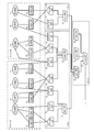
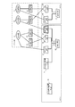
- FIG. 1 is a diagram showing an example of the overall configuration of the system according to the first embodiment.
- a virtual resource used by a plurality of tenants tenant A and tenant B
- a physical resource on which the virtual resource operates are included.
- a tenant is an example of a user (for example, a company) who uses a virtual machine.
- virtual resources are shown by a dot pattern.
- Virtual resources are, for example, virtual machines, virtual networks, volumes, and the like.
- Physical resources are, for example, physical servers, physical storage, physical switches, and the like.
- virtual resources and physical resources are shown in different forms for each type.
- A_DB01 (11), A_AP01 (12), A_WB01 (13), and A_WB02 (14) are virtual machines used by tenant A.
- B_DB01 (15), B_AP01 (16), and B_WB01 (17) are virtual machines used by tenant B.
- bl001_01 (21), vr001_02 (22), vr002_01 (23), vr002_02 (24), and lv002_03 (25) are volumes used by tenant A.
- vll003_01 (26), vl003_02 (27), vl004_01 (28), and vl004_02 (29) are volumes used by tenant B.
- store_001 (31), store_002 (32), store_003 (33), and store_004 (34) are physical storages.
- lv001_01 (21) and vr001_02 (22) operate on studio_001 (31).
- vll002_01 (23), vl002_02 (24), and vl002_03 (25) operate on studio_002 (32).
- vll003_01 (26) and vl003_02 (27) operate on studio_003 (33).
- vll004_01 (28) and vl004_02 (29) operate on studio_004 (34).
- Server_001 (41), server_002 (42), server_003 (43), server_004 (44), and server_005 (45) are physical servers.
- A_DB01 (11) uses v001_01 (21) and vl001_02 (22) and operates on server_001 (41).
- A_AP01 (12) uses vll002_01 (23) and operates on server_002 (42).
- A_WB01 (13) uses vll002_02 (24) and operates on server_002 (42).
- A_WB02 (14) uses vll002_03 (25) and operates on server_003 (43).
- Psw_001 (51), psw_002 (52), psw_003 (53), psw_004 (54), psw_005 (55), psw_006 (56), and psw_007 (57) are physical switches.
- store_001 (31), server_001 (41), and server_002 (42) connect to psw_001 (51).
- store_002 (32), store_003 (33), server_003 (43) and server_004 (44) connect to psw_002 (52).
- store_004 (34) and server_005 (45) connect to psw_003 (53).
- psw_001 51
- psw_002 52
- psw_003 53
- psw_004 54
- psw_005 55
- psw_006 56
- psw_007 57
- Rack_x, rack_y, and rack_z are racks on which physical resources are mounted.
- rack_x carries store_001 (31), studio_002 (32), studio_003 (33), server_001 (41), server_002 (42), server_003 (43), and server_004 (44).
- rack_x further carries psw_001 (51) and psw_002 (52).
- rack_y is equipped with store_004 (34), server_005 (45), and psw_003 (53).
- rack_z is equipped with psw_004 (54), psw_005 (55), psw_006 (56), and psw_007 (57).
- system in this embodiment may include a configuration other than the configuration shown in FIG.
- the administrator of tenant A identifies a physical resource having a high degree of influence on the operation of the virtual resource of tenant A by referring to the system configuration diagram as shown in FIG.
- the administrator can determine which physical resource has a high influence on the operation of the virtual resource of tenant A even by referring to the system configuration diagram. Is difficult.
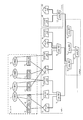
- FIG. 2 is a diagram showing a first display example of the system configuration.
- the first display example shown in FIG. 2 is a display example in the prior art of the system configuration provided by the cloud infrastructure administrator to the tenant A administrator.
- the physical resource on which the virtual resource of tenant A operates is displayed.
- the cloud infrastructure administrator can inform the administrator of the physical resources having a high influence on the operation of the tenant A. ..
- psw_002 (52) to which store_002 (32) and server_003 (43) are connected also connects to store_003 (33) and server_004 (44) in which the virtual resource of tenant B operates. Therefore, for example, when the communication load of psw_002 (52) increases due to an increase in the load of store_003 (33) or server_004 (44), store_002 (32) and server_003 (43) are also affected. Then, the virtual resource of tenant A operating on store_002 (32) and server_003 (43) is also affected. However, in the example shown in FIG. 2, store_003 (33) and server_004 (44) are not displayed. That is, in the example shown in FIG.
- the administrator of the tenant A identifies the physical resource (for example, studio_003 (33) or server_004 (44)) that is the cause of the abnormality of the virtual resource, even if the display example shown in FIG. 2 is referred to. Is difficult.
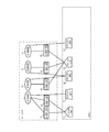
- FIG. 3 is a diagram showing a second display example of the system configuration.
- the second display example shown in FIG. 3 is a display example in the prior art of the system configuration provided by the cloud infrastructure administrator to the tenant A administrator.
- all physical resources that are directly or indirectly connected to the physical resource on which the virtual resource of tenant A operates are displayed.
- the second display example may include, for example, all the physical resources in the availability zone including the physical resource on which the virtual resource used by the tenant A operates.
- the second display example is likely to include a physical resource that causes an abnormality in tenant A, but also includes a physical resource that has a low degree of influence on the operation of the virtual resource of tenant A. .. Therefore, it is difficult for the manager of tenant A to identify a physical resource having a high degree of influence on tenant A even by referring to the display example shown in FIG.
- FIG. 4 is a diagram showing an example of the functional configuration of the information processing device 1 and the information processing terminal 2 in the first embodiment.
- the information processing device 1 includes a receiving unit 11, a first specific unit 12, a second specific unit 13, a third specific unit 14, a route selection unit 15, an output unit 16, and a storage unit 17.
- the information processing device 1 is, for example, a server included in the cloud infrastructure and managed by the administrator of the cloud infrastructure.
- the information processing device 1 is an example of a computer. At least one of the information processing device 1 and the information processing terminal 2 may be a virtual machine included in the system of FIG.
- the receiving unit 11 receives the tenant identification information from the information processing terminal or the like used by the administrator of the customer system.
- the tenant identification information received by the receiving unit 11 is the tenant identification information designated as the survey target by the administrator of the customer system.
- the tenant indicated by the identification information received by the receiving unit 11 may be referred to as a designated tenant.
- the receiving unit 11 receives management information regarding the cloud infrastructure used by the designated tenant.
- the designated tenant is an example of a first user.
- the management information regarding the cloud infrastructure used by the designated tenant may be referred to as management information.
- the details of the management information will be described later.
- the first specific unit 12 identifies one or a plurality of physical resources on which the virtual resource used by the designated tenant operates.
- the physical resource specified by the first specific unit 12 may be referred to as a first physical resource.
- the second specific unit 13 identifies a device connected to the first physical resource specified by the first specific unit 12 and one or a plurality of physical resources connected to the device and different from the first physical resource.
- the physical resource specified by the second specific unit 13 may be referred to as a second physical resource.
- the second physical resource is, for example, a physical resource on which a virtual resource used by a tenant different from the designated tenant operates.
- the device specified by the second specific unit 13 is a device that is directly connected to the first physical resource, and does not include a device that is connected to the first physical resource via another physical resource. Further, it is assumed that the second physical resource specified by the second specific unit 13 is a physical resource that directly connects to the specified device, and does not include a physical resource that connects to the specified device via another physical resource. ..
- the second identification unit 13 identifies a communication device connected to the first physical resource, connects to the communication device, and operates one or a plurality of second physical devices in which virtual resources used by tenants other than the designated tenant operate. Resources may be identified.
- the communication device is, for example, a physical router or a physical switch. In this embodiment, a physical switch is applied as a communication device. For example, when a failure or congestion occurs in a communication device connected to the first physical resource, a processing delay or the like may occur in the virtual resource operating on the first physical resource.
- the second specifying unit 13 may specify the wiring plug-in device to be connected to the first physical resource. Then, the second specific unit 13 connects to the wiring plug-in device, and one or a plurality of second physical resources on which virtual resources used by tenants different from the designated tenant operate, and the wiring plug-in.
- the communication device connected to the device may be specified.
- Wiring plugs are connectors for supplying power to physical resources, such as outlets, cord connector bodies, and multi-tap.
- the device is, for example, a communication device (relay device) of layer 2 or higher, and the second specific unit 13 is a layer 2 or higher other device with the device when specifying one or a plurality of second physical resources.
- the physical resource connected via the communication device (relay device) of the above may be controlled so as not to be specified as the second physical resource. This makes it possible to prevent the identification of an excessive number of second physical resources.
- the third specific unit 14 specifies the operating status of the first physical resource and the second physical resource.
- the third specific unit 14 may specify the operating status of the communication device specified by the second specific unit 13.
- the third specific unit 14 identifies, for example, the physical resource in which the failure has occurred among the first physical resource, the second physical resource, and the communication device. Failures include, for example, equipment failure, communication congestion, and earth leakage.
- the route selection unit 15 specifies a communication device connected to the first physical resource by the second specific unit 13, and when a plurality of the communication devices exist, the shortest communication among the communication paths connecting the plurality of communication devices. Select a route.
- the shortest communication path among the communication paths connecting a plurality of communication devices connected to the first physical resource may be simply referred to as the shortest communication path. Then, the route selection unit 15 identifies the communication device existing in the shortest communication path.
- the output unit 16 outputs information indicating the first physical resource specified by the first specific unit 12 and information indicating the second physical resource specified by the second specific unit 13.
- the output unit 16 causes the display device to display, for example, the identification information of the first physical resource and the identification information of the second physical resource.
- the display device may be mounted on the information processing device 1 or may be connected to the information processing device 1.
- the output unit 16 may transmit, for example, information indicating the first physical resource and information indicating the second physical resource to the external information processing terminal 2.
- the output unit 16 may output information indicating the communication device.
- the information indicating the communication device is, for example, identification information of the communication device.
- the output unit 16 may output the identification information of the first physical resource, the second physical resource, and the communication device in a mode corresponding to the operation status specified by the third specific unit 14.
- the output unit 16 is, for example, information indicating a failed physical resource and information indicating other physical resources specified in the third specific unit 14 among the first physical resource, the second physical resource, and the communication device. May be output in different modes.
- the output unit 16 may output the information indicating the first physical resource and the information indicating the second physical resource in different modes.
- the output unit 16 may output information indicating a communication device existing in the shortest communication path selected by the route selection unit 15.
- the output unit 16 provides information indicating the communication device. May be output.
- the output unit 16 may output a system configuration diagram of the cloud infrastructure including information indicating the first physical resource and information indicating the second physical resource. Further, the output unit 16 may output a hierarchical list of information indicating each physical resource in the cloud infrastructure including the first physical resource and the second physical resource.
- the storage unit 17 stores the management information received by the reception unit 11 regarding the cloud infrastructure used by the designated tenant.
- the storage unit 17 may store management information in advance.
- the information processing terminal 2 is connected to the information processing device 1.
- the display unit 21 of the information processing terminal 2 displays based on the information output from the output unit 16.
- FIG. 5 is a diagram showing an example of information showing the relationship between the tenant and the virtual machine in the first embodiment.
- the identification information of the tenant and the identification information of the virtual machine used by the tenant are associated with each other.
- FIG. 6 is a diagram showing an example of information showing the relationship between the tenant and the volume in the first embodiment.
- the identification information of the tenant and the identification information of the volume used by the tenant are associated with each other.
- the first specific unit 12 can specify the virtual resources (virtual machines and volumes) used by the designated tenant by referring to the information shown in FIGS. 5 and 6.
- FIG. 7 is a diagram showing an example of information showing the relationship between the virtual machine and the physical server in the first embodiment.
- the identification information of the virtual machine and the identification information of the physical server on which the virtual machine operates are associated with each other.
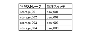
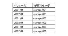
- FIG. 8 is a diagram showing an example of information showing the relationship between the volume and the physical storage in the first embodiment.
- the identification information of the volume and the identification information of the physical storage in which the volume operates are associated with each other.
- the first specific unit 12 refers to the information shown in FIGS. 5 to 8 and refers to the first physical resource (physical server and physical storage) on which the virtual resource (virtual machine and volume) used by the designated tenant operates. Can be identified.
- FIG. 9 is a diagram showing an example of information showing the relationship between the physical server and the rack in the first embodiment.
- the identification information of the physical server and the identification information of the rack on which the physical server is mounted are associated with each other.
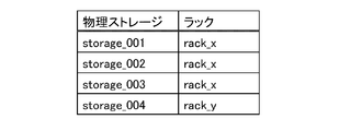
- FIG. 10 is a diagram showing an example of information showing the relationship between the physical storage and the rack in the first embodiment.
- the identification information of the physical storage and the identification information of the rack on which the physical storage is mounted are associated with each other.
- the second specific unit 13 refers to the wiring plug-in device connected to the first physical resource (physical server and physical storage) and the wiring plug-in device by referring to the information shown in FIGS. 9 and 10. Identify the second physical resource to connect to.
- the second specifying unit 13 refers to the information shown in FIGS. 9 and 10 to identify the rack associated with the first physical resource, and thereby connects to the first physical resource for wiring. Identify the device. Then, the second specifying unit 13 connects to the specified wiring plug-in device by specifying the physical resource associated with the specified rack with reference to the information shown in FIGS. 9 to 11. 2 Identify physical resources and communication equipment.
- FIG. 12 is a diagram showing an example of information showing the relationship between the physical server and the physical switch in the first embodiment.
- the identification information of the physical server and the identification information of the physical switch connected to the physical server are associated with each other.
- FIG. 13 is a diagram showing an example of information showing the relationship between the physical storage and the physical switch in the first embodiment.
- the identification information of the physical storage and the identification information of the physical switch connected to the physical storage are associated with each other.
- the second specifying unit 13 identifies the communication device (physical switch) and the second physical resource connected to the first physical resource (physical server and physical storage) by referring to the information shown in FIGS. 12 and 13. be able to.
- the second specifying unit 13 refers to the information shown in FIGS. 12 and 13 to specify the communication device associated with the first physical resource, thereby determining the communication device connected to the first physical resource. Identify. Then, the second physical unit 13 connects to the specified communication device by specifying the physical resource associated with the specified communication device with reference to the information shown in FIGS. 12 and 13. Identify the resource.
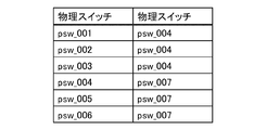
- FIG. 14 is a diagram showing an example of information showing the connection relationship of the physical switches in the first embodiment.
- the identification information of the physical switch and the identification information of the physical switch connected to the physical switch are associated with each other.
- the route selection unit 15 refers to the information shown in FIG. 14 and refers to the shortest communication path among the communication devices connecting the plurality of communication devices (physical switches). Select a communication path and identify the communication device that exists within the shortest communication path.
- FIG. 15 is a diagram showing an example of information indicating the presence or absence of a failure of physical resources in the first embodiment.
- the identification information of the physical resource (physical server, physical storage, and physical switch) is associated with the presence or absence of a failure of the physical resource.
- the information shown in FIG. 15 may include, for example, the content of the failure.
- the third specific unit 14 can identify the physical resource in which the failure has occurred among the first physical resource, the second physical resource, and the communication device, based on the information shown in FIG.
- Each information shown in FIGS. 5 to 15 is stored in the storage unit 17 as management information related to the cloud infrastructure.
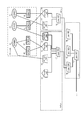
- FIG. 16 is a diagram showing a third display example of the system configuration.
- the first specifying unit 12 specifies the first physical resource on which the virtual resource used by the tenant A operates.
- the first physical resources in the example shown in FIG. 16 are store_001 (31), studio_002 (32), server_001 (41), server_002 (42), and server_003 (43).
- the second specific unit 13 specifies psw_001 (51) and psw_002 (52) as communication devices connected to the first physical resource specified by the first specific unit 12. Further, the second specific unit 13 connects to psw_001 (51) or psw_002 (52) and specifies a second physical resource on which a virtual resource used by a tenant B different from the designated tenant operates.
- the second physical resources in the example shown in FIG. 16 are store_003 (33) and server_004 (44).
- the third specific unit 14 refers to the information shown in the example of FIG. 15 and identifies the physical resource (server_004 (44)) in which the failure has occurred among the first physical resource, the second physical resource, and the communication device.
- the output unit 16 displays the above-mentioned identification information of the first physical resource, the identification information of the second physical resource, and the identification information of the communication device connected to the first physical resource. Further, the output unit 16 displays the identification information (server_004 (44)) of the physical resource in which the failure has occurred and the identification information of the other physical resource specified by the third specific unit 14 in different modes. For example, as shown in FIG. 16, the output unit 16 highlights an icon including identification information of the physical resource in which the failure has occurred. The output unit 16 may display the icon indicating the physical resource in which the failure has occurred and the icon indicating another physical resource in different colors or different forms. The output unit 16 may display the identification information of the physical resource in which the failure has occurred in different modes depending on the content of the failure and the like.
- the communication device connected to the first physical resource and the second physical resource connected to the communication device are likely to affect the virtual resource operating on the first physical resource. Therefore, by displaying the system configuration shown in FIG. 16, the information processing device 1 can notify the manager of the tenant A of the physical resources having a high degree of influence on the operation of the virtual resources of the tenant A. The administrator of the tenant A can quickly identify the cause of the virtual resource in which the abnormality has occurred, for example, by preferentially investigating the displayed physical resource.
- the identification information of the physical resource in which the failure has occurred (server_004 (44)) and the identification information of the other physical resource are displayed in different modes. Therefore, the administrator of tenant A can presume that the cause of the abnormality of the virtual resource is server_004 (44). As a result, the administrator of tenant A can quickly know whether the cause of the virtual resource in which the abnormality has occurred exists in the physical resource or the virtual resource in the cloud infrastructure.
- A_WB02 (14) it is assumed that a processing delay or the like occurs in A_WB02 (14), and the physical resource in which the failure occurs is only resource_001 (31).
- the first physical resource is only A_WB02 (14)
- storage_001 (31) does not correspond to the second physical resource specified by the second specific unit 13, so that it is not displayed.
- the user can infer that there is a problem with the virtual resource (A_WB02 (14)) instead of the physical resource.
- FIG. 17 is a diagram showing a fourth display example of the system configuration.
- the fourth display example shown in FIG. 17 is different from the example shown in FIG. 16 in that the information indicating the first physical resource and the information indicating the second physical resource are displayed in different modes.
- the other devices (2 units) 61 in FIG. 17 are simple displays of the second physical resources (store_003 (33) and server_004 (44)). Since it is considered that the second physical resource is less likely to affect the designated tenant than the first physical resource, the second physical resource is simply displayed.
- the output unit 16 displays the physical resource in a normal display instead of a simple display (FIG. 16). (Similar display) may be used.
- the output unit 16 may hide physical resources other than the physical resource in which the failure has occurred among the second physical resources.
- the information processing device 1 can more easily identify the physical resource that causes the abnormality by outputting the display example shown in FIG.
- FIGS. 16 and 17 show an example in which the processing by the route selection unit 15 is not performed, the processing by the route selection unit 15 is executed, and the output unit 16 performs the shortest communication selected by the route selection unit 15.
- the identification information of the communication device existing in the route may be output.
- FIG. 18 is a diagram showing a fifth display example of the system configuration.
- the designated tenant is tenant B.
- the first specifying unit 12 specifies the first physical resource on which the virtual resource used by the tenant B operates.
- the first physical resources in the fifth display example are store_003 (33), studio_004 (34), server_003 (43), server_004 (44), and server_005 (45).
- the second specific unit 13 specifies a wiring plug device to be connected to the first physical resource specified by the first specific unit 12. Then, the second specific unit 13 is connected to the wiring plug-in device, and one or a plurality of second physical resources on which virtual resources used by tenants different from the designated tenant operate, and the wiring plug-in device. Identify the communication device to connect to. As mentioned above, the physical resources existing in the same rack are connected to the same wiring plug-in device. Therefore, the second specific unit 13 refers to the information shown in FIGS. 9 to 11 and refers to the second physical resource mounted on the rack (rac_x, rack_y) on which the first physical resource is mounted and the communication device. To identify.
- the second specific unit 13 specifies studio_001 (31), studio_002 (32), server_001 (41), and server_002 (42) as the second physical resource. Further, the second specifying unit 13 identifies psw_001 (51), psw_002 (52), and psw_003 (53) as communication devices.
- the third specific unit 14 refers to the information shown in the example of FIG. 15 and identifies the physical resource (server_004 (44)) in which the failure has occurred among the first physical resource, the second physical resource, and the communication device.
- the output unit 16 displays the identified first physical resource identification information, the second physical resource identification information, and the communication device identification information. Further, the output unit 16 displays the identification information (server_004 (44)) of the physical resource in which the failure has occurred and the identification information of the other physical resource specified by the third specific unit 14 in different modes. ..
- the information processing device 1 displays the identification information of the second physical resource and the communication device connected to the wiring plug device connected to the first physical resource, so that the degree of influence on the operation of the virtual resource of the tenant B is increased. High physical resources can be notified to the administrator of tenant B.
- FIG. 19 is a diagram showing a sixth display example of the system configuration.
- the example shown in FIG. 19 differs from the example shown in FIG. 18 in that store_001 (31), studio_002 (32), server_001 (41), server_002 (42), and psw_001 (51) are simply displayed.
- the other device (1 unit) 62 is a simple display of storage_002 (32).
- the other devices (4 units) 63 are simple displays of store_001 (31), server_001 (41), server_002 (42), and psw_001 (51).
- Store_001 (31), store_002 (32), server_001 (41), and server_002 (42) are the second physical resources.
- the output unit 16 outputs the identification information indicating the first physical resource and the identification information indicating the second physical resource in different modes.
- Psw_002 (52) and psw_003 (53) are communication devices connected to the first physical resource.
- the psw_001 (51) is a communication device connected to a wiring plug device connected to the first physical resource and not connected to the first physical resource.
- the output unit 16 connects to the identification information of the communication device connected to the first physical resource and the communication device connected to the wiring plug-in device connected to the first physical resource and not connected to the first physical resource.
- the identification information of is output in a different manner.
- a communication device that connects to a wiring plug-in device that connects to the first physical resource but does not connect to the first physical resource becomes a virtual resource that operates on the first physical resource, compared to a communication device that connects to the first physical resource. It is considered that the degree of influence of is low. Therefore, the information processing apparatus 1 can more easily identify the physical resource that causes the abnormality by outputting the display example shown in FIG.
- FIG. 20 is a diagram showing a seventh display example of the system configuration.
- the designated tenant is tenant B.
- the first specifying unit 12 specifies the first physical resource on which the virtual resource used by the tenant B operates.
- the first physical resources in the seventh display example are store_003 (33), and store_004 (34), server_003 (43), server_004 (44), and server_005 (45).
- the second specific unit 13 specifies psw_002 (52) and psw_003 (53) as communication devices connected to the first physical resource specified by the first specific unit 12.
- the second specifying unit 13 connects to psw_002 (52) and psw_003 (53), and identifies a second physical resource on which a virtual resource used by tenant A different from the designated tenant operates.
- the second physical resource in the seventh display example is storage_002 (32).
- the third specific unit 14 refers to the information shown in the example of FIG. 15 and identifies the physical resource (server_004 (44)) in which the failure has occurred among the first physical resource, the second physical resource, and the communication device.
- the route selection unit 15 selects the shortest communication route among the communication routes connecting psw_002 (52) and psw_003 (53). Then, the route selection unit 15 identifies the communication device (psw_004 (54)) existing in the shortest communication path. Further, the route selection unit 15 may further specify another communication device connected to the wiring plug-in device to which the communication device existing in the shortest communication path is connected based on the information shown in FIG. In the example shown in FIG. 20, other communication devices are psw_005 (55), psw_006 (56), and psw_007 (57).
- the output unit 16 displays the identified first physical resource identification information, the second physical resource identification information, and the communication device identification information. Further, the output unit 16 displays the identification information (server_004 (44)) of the physical resource in which the failure has occurred and the identification information of the other physical resource specified by the third specific unit 14 in different modes.
- the output unit 16 outputs the identification information (psw_004 (54)) of the communication device existing in the shortest communication path selected by the route selection unit 15. Then, the output unit 16 further outputs the identification information (psw_005 (55), psw_006 (56), and psw_007 (57)) of the other communication device connected to the wiring plug device to which the communication device is connected. May be good.
- the shortest communication path between a plurality of communication devices connected to the first physical resource selected by the route selection unit 15 is likely to be a communication path when communicating between the first physical resources. Therefore, if a failure or congestion occurs in a communication device existing in the shortest communication path, a processing delay or the like may occur in the virtual resource operating on the first physical resource. Therefore, the information processing device 1 can notify the administrator of the tenant B of the communication device having a high degree of influence on the operation of the virtual resource of the tenant B by displaying the seventh display example shown in FIG.
- FIG. 21 is a diagram showing an eighth display example of the system configuration.
- the example shown in FIG. 21 differs from the example shown in FIG. 20 in that store_002 (32), psw_005 (55), psw_006 (56), and psw_007 (57) are simply displayed.
- the other device (1 unit) 62 is a simple display of storage_002 (32).
- the other devices (3 units) 64 are simple displays of psw_005 (55), psw_006 (56), and psw_007 (57).
- the route selection unit 15 identifies another communication device connected to the wiring plug-in device to which the communication device existing in the shortest communication path is connected. Then, when the other communication device is not connected to the first physical resource, the output unit 16 uses different modes for the identification information of the communication device existing in the shortest communication path and the identification information of the other communication device. Output.
- the identification information of the communication device existing in the shortest communication path is psw_004 (54), and the identification information of the other communication device is the other device (3 units) 64.
- the output unit 16 outputs, for example, a system configuration diagram of a cloud platform including information indicating a first physical resource and information indicating a second physical resource.
- a system configuration diagram of a cloud platform including information indicating a first physical resource and information indicating a second physical resource.
- FIG. 22 is a diagram showing a ninth display example of the system configuration.
- the output unit 16 may list the identification information of each virtual resource and the identification information of each physical resource together with an icon indicating the virtual resource and the type of the physical resource.
- icons shown in FIG. 22 “VM” indicates a virtual machine.
- the output unit 16 causes the display device to display, for example, the figures shown in FIGS. 16 to 22 described above. Further, the output unit 16 may output the information used for the display shown in FIGS. 16 to 22 to the information processing terminal 2, and the information processing terminal 2 may display the display example shown in FIGS. 16 to 22.
- the information processing device 1 can notify the administrator of tenant A of a physical resource having a high degree of influence on the operation of the virtual resource. Further, the information processing device 1 can inform the manager of the tenant A of the hierarchical structure of the cloud infrastructure including the first physical resource and the second physical resource.
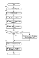
- FIG. 23 is a flowchart showing a first example of the processing of the first embodiment.
- the first example of the processing of the first embodiment is an example in which the second specifying unit 13 specifies a communication device as a device.
- the receiving unit 11 receives the tenant identification information from the information processing terminal or the like of the administrator of the customer system (step S101).
- the tenant identification information is the tenant identification information designated as the survey target by the administrator of the customer system.
- the receiving unit 11 receives the management information regarding the cloud infrastructure used by the designated tenant (step S102).
- the first specific unit 12 identifies one or a plurality of first physical resources on which the virtual resource used by the designated tenant operates (step S103).
- the second specific unit 13 specifies a communication device connected to the first physical resource specified by the first specific unit 12 (step S104).
- the second specifying unit 13 connects to the communication device and identifies one or a plurality of second physical resources on which virtual resources used by tenants different from the designated tenant operate (step S105).
- the route selection unit 15 determines whether or not there are a plurality of communication devices specified by the second specific unit 13 in step S104 (step S106). When there are a plurality of communication devices specified by the second specific unit 13 (YES in step S106), the route selection unit 15 selects the shortest communication path among the communication paths connecting the plurality of communication devices, and the shortest communication path is selected. The communication device existing in the communication path of (step S107) is specified.
- the third specific unit 14 specifies the specified first physical resource, the second physical resource, and the operating status of the communication device (step S108). For example, the third specific unit 14 identifies the physical resource in which the failure has occurred among the specified first physical resource, the second physical resource, and the communication device.
- the output unit 16 outputs information indicating the first physical resource, information indicating the second physical resource, and information indicating the communication device specified by the second specific unit 13 (step S109).
- the output unit 16 may output the information indicating the first physical resource and the information indicating the second physical resource in different modes.
- the output unit 16 provides information indicating the first physical resource, information indicating the second physical resource, and information indicating the communication device specified by the second specific unit 13 according to the operation status specified by the third specific unit 14. It may be output in the above manner.
- the output unit 16 may output information indicating the communication device.
- the information processing device 1 can notify the manager of the tenant of the physical resources having a high influence on the operation of the virtual resources without excess or deficiency. Further, the information processing device 1 outputs information indicating the second physical resource specified based on the communication connection status, so that the physical resource that is likely to affect the virtual resource when a communication failure occurs can be obtained. You can notify the tenant administrator.
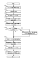
- FIG. 24 is a flowchart showing a second example of the processing of the embodiment.
- the second example of the processing of the embodiment is an example in which the second specific unit 13 specifies a wiring plug-in device as a device. Since steps S201 to S203 are the same as steps S101 to S103 in FIG. 23, the description thereof will be omitted.
- the route selection unit 15 determines whether or not there are a plurality of wiring plug-in devices specified by the second specific unit 13 in step S204 (step S206). When there are a plurality of wiring plug-in devices specified by the second specific unit 13 (YES in step S206), the route selection unit 15 is the shortest communication path among the communication paths connecting the plurality of wiring plug-in devices. A route is selected, and a communication device existing in the shortest communication path is specified (step S207).
- the third specific unit 14 specifies the operation status of the specified first physical resource, second physical resource, and communication device (step S208).
- the third specific unit 14 identifies the physical resource in which the failure has occurred among the specified first physical resource, second physical resource, and communication device.
- the output unit 16 outputs information indicating the first physical resource, information indicating the second physical resource, and information indicating the communication device specified by the second specific unit 13 (step S209).
- the output unit 16 may output the information indicating the first physical resource and the information indicating the second physical resource in different modes.
- the output unit 16 provides information indicating the first physical resource, information indicating the second physical resource, and information indicating the communication device specified by the second specific unit 13 according to the operation status specified by the third specific unit 14. It may be output in the above manner.
- the output unit 16 may output information indicating the communication device.
- the information processing device 1 can notify the manager of the tenant of the physical resource having a high degree of influence on the operation of the virtual resource. Further, the information processing device 1 has a high possibility of affecting the virtual resource in the event of an electrical system failure by outputting information indicating the second physical resource specified based on the connection status of the electrical wiring. Physical resources can be communicated to the tenant administrator.
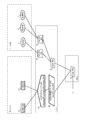
- FIG. 25 is a diagram showing an outline of the processing of the embodiment.
- the system configuration shown in the upper part of FIG. 25 is the same as the system configuration shown in FIG. 1, and the display example shown in the lower part of FIG. 25 is the same as the fourth display example shown in FIG.
- the information processing device 1 performs the processing of the present embodiment based on the system configuration shown in the upper part of FIG. 25, and outputs, for example, a display example shown in the lower part of FIG. 25.
- the tenant administrator can easily identify the cause of the abnormality of the virtual resource as compared with the case of referring to the complicated system configuration diagram.
- FIG. 26 is a diagram showing an example of the overall configuration of the system according to the second embodiment.
- virtual resources used by a plurality of tenants (tenant A and tenant B) and physical resources on which the virtual resources operate are included.
- the notation method in FIG. 26 is the same as that in FIG.
- bl001_01 (21) and vr002_01 (23) are volumes used by tenant A. Further, B_DB01 (15), B_AP01 (16), and B_WB01 (17) are virtual machines used by tenant B.
- store_001 (31), store_002 (32), and store_003 (33) are physical storages.
- server_001 (41) and server_002 (42) are physical servers.
- Vl001_01 (21) and vl002_01 (23) operate on store_001 (31), store_002 (32), and store_003 (33).
- B_DB01 (15) operates on server_001 (41).
- B_AP01 (16) and B_WB01 (17) operate on server_002 (42).
- Psw_001 (51), psw_002 (52), psw_003 (53), psw_004 (54) are physical switches.
- store_001 (31), store_002 (32), and store_003 (33) connect to psw_001 (51) and psw_002 (52).
- server_001 (41) and server_002 (42) connect to psw_003 (53).
- psw_001 (51), psw_002 (52), and psw_003 (53) connect to psw_004 (54).
- Rack_x and rack_z are racks on which physical resources are mounted.
- the rack_x is equipped with store_001 (31), studio_002 (32), studio_003 (33), server_001 (41), and server_002 (42).
- rack_x further carries psw_001 (51), psw_002 (52), and psw_003 (53).
- rack_z is equipped with psw_004 (54).
- FIG. 27 is a diagram showing an example of the functional configuration of the information processing device 1 and the information processing terminal 2 in the second embodiment. At least one of the information processing device 1 and the information processing terminal 2 may be a virtual machine included in the system of FIG. 26.
- the information processing device 1 includes a receiving unit 11, a first specific unit 12, a second specific unit 13, a third specific unit 14, a route selection unit 15, an output unit 16, a storage unit 17, a collecting unit 18, and a fourth specific unit 19. And include. Since the functions of the receiving unit 11, the first specific unit 12, the second specific unit 13, the third specific unit 14, the route selection unit 15, and the storage unit 17 are the same as those in the first embodiment, the description thereof will be omitted.
- the collection unit 18 collects the physical connection status and virtual resource operation status of the first physical resource specified by the first specific unit 12 or the second physical resource specified by the second specific unit 13 for each physical resource.
- the collecting unit 18 may collect the physical connection status of the communication device specified by the second specific unit 13 for each communication device.
- the virtual resource operating on the plurality of physical resources is the same, and the other physical resources connected to the plurality of physical resources are the same. If so, identify the multiple physical resources as redundant physical resources.
- the fourth specific unit 19 uses the information collected by the collection unit 18 when performing the identification process.
- the output unit 16 may execute the process described below together with the process executed by the output unit 16 of the first embodiment.
- the output unit 16 provides information indicating a plurality of physical resources (redundant physical resources) specified by the fourth specific unit 19 when outputting information indicating the first physical resource and information indicating the second physical resource. Output as one node. Therefore, the output unit 16 can make the configuration easy to understand by outputting a plurality of redundant physical resources specified by the fourth specific unit 19 as one node.
- the output unit 16 may display an icon indicating the presence or absence of a failure of each physical resource in a node indicating a plurality of redundant physical resources. For example, the output unit 16 may display the icon corresponding to the physical resource in which the failure has occurred and the icon corresponding to the physical resource in which the failure has not occurred in different modes.
- the output unit 16 may display information indicating a plurality of physical resources specified by the fourth specific unit 19 on the display device as one node, or output an instruction to display the information as one node to the information processing terminal 2. You may. This instruction may include the presence / absence of display of the above icon, the display mode, and the like.
- the display device may be mounted on the information processing device 1 or may be connected to the information processing device 1.
- the information processing terminal 2 is connected to the information processing device 1.
- the display unit 21 of the information processing terminal 2 displays based on the information output from the output unit 16.
- the information processing terminal 2 displays, for example, information indicating a plurality of physical resources specified by the fourth specific unit 19 as one node based on an instruction from the output unit 16.
- management information information indicating the relationship between the tenant and the virtual machine, information indicating the relationship between the tenant and the volume, information indicating the relationship between the physical server and the rack, information indicating the relationship between the physical storage and the rack, and information indicating the relationship between the physical storage and the rack, and the physical switch and rack.
- the illustration of the information indicating the relationship between the above is omitted.
- FIG. 28 is a diagram showing an example of information showing the relationship between the virtual machine and the physical server in the second embodiment.
- the identification information of the virtual machine and the identification information of the physical server on which the virtual machine operates are associated with each other.
- FIG. 29 is a diagram showing an example of information showing the relationship between the volume and the physical storage in the second embodiment.
- the identification information of the volume and the identification information of the physical storage in which the volume operates are associated with each other.
- FIG. 30 is a diagram showing an example of information showing the relationship between the physical server and the physical switch in the second embodiment.
- the identification information of the physical server and the identification information of the physical switch connected to the physical server are associated with each other.
- FIG. 31 is a diagram showing an example of information showing the relationship between the physical storage and the physical switch in the second embodiment.
- the identification information of the physical storage and the identification information of the physical switch connected to the physical storage are associated with each other.
- FIG. 32 is a diagram showing an example of information showing the connection relationship of the physical switches in the second embodiment.
- the identification information of the physical switch and the identification information of the physical switch connected to the physical switch are associated with each other.
- FIG. 33 is a diagram showing an example of information indicating the presence or absence of a failure of the physical resource in the second embodiment.
- the identification information of the physical resource (physical server, physical storage, and physical switch) is associated with the presence or absence of a failure of the physical resource.
- the information shown in FIG. 33 may include, for example, the content of the failure.
- the third identification unit 14 can identify the physical resource in which the failure has occurred among the first physical resource, the second physical resource, and the communication device.
- FIG. 34 is a diagram showing an example of the collected information of the physical storage in the second embodiment.
- the collected information shown in FIG. 34 is information obtained by the collecting unit 18 collecting the physical connection status and virtual resource operating status of the first physical resource or the second physical resource for each physical resource (physical storage).
- the physical connection status of the physical resource and the virtual resource operating status of the studio_001, the studio_002, and the studio_003 are the same. That is, the virtual resources operating in store_001, store_002, and store_003 are the same, and the other physical resources connected to studio_001, store_002, and store_003 are the same. Therefore, the fourth specific unit 19 specifies studio_001, studio_002, and studio_003 as redundant physical resources.
- FIG. 35 is a diagram showing an example of the collected information of the physical switch in the second embodiment.
- the collected information shown in FIG. 35 is information obtained by the collecting unit 18 collecting the physical connection status of the physical switches for each physical switch.
- psw_001 and psw_002 have the same physical connection status of physical resources. That is, the other physical resources connected to psw_001 and psw_002 are the same. Therefore, the fourth specific unit 19 specifies psw_001 and psw_002 as redundant physical resources.
- FIG. 36 is a diagram showing a tenth display example of the system configuration.
- the output unit 16 outputs a plurality of physical resources (redundant physical resources) specified by the fourth specific unit 19 when outputting the information indicating the first physical resource and the information indicating the second physical resource. Is output as one node.
- the output unit 16 since studio_001, studio_002, and studio_003 are specified as redundant physical resources, the output unit 16 outputs studio_001, studio_002, and studio_003 as one node (redundant storage 61).
- psw_001 and psw_002 are specified as redundant physical resources, the output unit 16 outputs psw_001 and psw_002 as one node (redundant physical switch 62). That is, the output unit 16 collectively displays a plurality of physical resources specified by the fourth specific unit 19 as if they were one physical resource.
- the information processing device 1 of the present embodiment can make the configuration easy to understand by outputting a plurality of physical resources together as one node.
- FIG. 37 is a diagram showing an eleventh display example of the system configuration.
- a redundant storage 61 and a redundant physical switch 62 in which a plurality of physical resources are integrated are shown.
- icons 61a to 61c indicating the operating status of each physical resource (storyage_001, studio_002, studio_003) are shown in the redundant storage 61.
- icons 62a and 62b indicating the operating status of each physical resource (psw_001, psw_002) are shown in the redundant physical switch 62.
- the icon 61a corresponding to the failed storage_001 is displayed in a manner different from the other icons 61b and 61c in the redundant storage 61.
- the output unit 16 displays an icon indicating the presence or absence of a failure of each physical resource in the node in which a plurality of redundant physical resources are grouped, and the icon corresponding to the physical resource in which the failure has occurred and the failure. Is displayed in a different manner from the icon corresponding to the physical resource in which is not generated. As a result, the user can know whether or not each physical resource has a failure.
- FIG. 38 is a flowchart showing a first example of the processing of the second embodiment.
- the first example is an example in which the second specific unit 13 specifies a communication device as a device.
- steps S301 to S308 are the same as steps S101 to 108 in the flowchart of the first embodiment shown in FIG. 23, and thus the description thereof will be omitted.
- the collection unit 18 determines the physical connection status and virtual resource operation status of the first physical resource specified in the first specific unit 12 in step S303 or the second physical resource specified in the second specific unit 13 in step S305. Collect every time (step S309).
- the information obtained in the process of step S309 is, for example, the information shown in FIG. 34. Further, the collecting unit 18 may collect the physical connection status (for example, FIG. 35) of the communication device specified in the second specific unit 13 in step S304 for each communication device.
- the virtual resource operating on the plurality of physical resources is the same, and the other physical resources connected to the plurality of physical resources are the same.
- the plurality of physical resources are specified as redundant physical resources (step S310).
- the communication devices for example, physical switches
- the communication devices for example, physical switches
- the fourth specific unit 19 specifies the information.
- Information indicating the plurality of physical resources (redundant physical resources) that have been created is output as one node (step S311).
- FIG. 39 is a flowchart showing a second example of the processing of the second embodiment.
- the second example is an example in which the second specific unit 13 specifies a wiring plug-in device as a device.
- steps S401 to S408 are the same as steps S201 to 208 in the flowchart of the second example of the first embodiment shown in FIG. 24, and thus the description thereof will be omitted.
- steps S409 to S411 is the same as the processing of steps S309 to 311 of FIG. 38.
- the second example is different from the first example in that the fourth specific unit 19 does not specify a plurality of communication devices.
- FIG. 40 is a diagram showing an example of the hardware configuration of the information processing device 1.
- the processor 111, the memory 112, the auxiliary storage device 113, the communication interface 114, the medium connection unit 115, the input device 116, and the output device 117 are connected to the bus 100.
- the processor 111 executes the program expanded in the memory 112.
- An information processing program that performs processing according to the embodiment may be applied to the program to be executed.
- the memory 112 is, for example, Random Access Memory (RAM).
- the auxiliary storage device 113 is a storage device that stores various types of information, and for example, a hard disk drive, a semiconductor memory, or the like may be applied.
- the information processing program that performs the processing of the embodiment may be stored in the auxiliary storage device 113.
- the communication interface 114 is connected to a communication network such as a Local Area Network (LAN) or Wide Area Network (WAN), and performs data conversion and the like associated with the communication.
- the receiving unit 11 shown in FIGS. 4 and 27 may receive each information via, for example, the communication interface 114.
- the output unit 16 shown in FIGS. 4 and 27 may output each information to another information processing terminal or the like via, for example, the communication interface 114.
- the medium connection unit 115 is an interface to which the portable recording medium 118 can be connected.
- An optical disc for example, Compact Disc (CD) or Digital Versatile Disc (DVD), etc.
- a semiconductor memory or the like may be applied to the portable recording medium 118.
- An information processing program that performs the processing of the embodiment may be recorded on the portable recording medium 118.
- the input device 116 is, for example, a keyboard, a pointing device, or the like, and receives instructions and information input from the user.
- the output device 117 is, for example, a display device, a printer, a speaker, or the like, and outputs an inquiry or instruction to a user, a processing result, or the like.
- the output unit 16 shown in FIGS. 4 and 27 may output each information by using, for example, an output device 117.
- the storage unit 17 shown in FIGS. 4 and 27 may be realized by a memory 112, an auxiliary storage device 113, a portable recording medium 118, or the like. Even if the first specific unit 12, the second specific unit 13, the third specific unit 14, and the route selection unit 15 shown in FIG. 4 are realized by the processor 111 executing the information processing program expanded in the memory 112. Good.
- the memory 112, the auxiliary storage device 113, and the portable recording medium 118 are computer-readable and non-temporary tangible storage media, not temporary media such as a signal carrier wave.
- the information processing device 1 may not include all the components shown in FIG. 40, and some components may be omitted. Further, some components may exist in the external device of the information processing device 1, and the information processing device 1 may be connected to the external device to use the components in the external device. Further, it is assumed that the hardware configuration of the information processing terminal 2 is the same as the configuration shown in FIG. 40.
- the present embodiment is not limited to the above-described embodiment, and various changes, additions, and omissions can be applied within a range that does not deviate from the gist of the present embodiment.
- Information processing device 2 Information processing terminal 11 Reception unit 12 1st specific unit 13 2nd specific unit 14 3rd specific unit 15 Route selection unit 16 Output unit 17 Storage unit 18 Collection unit 19 4th specific unit 21 Display unit 100 Bus 111 Processor 112 Memory 113 Auxiliary storage 114 Communication interface 115 Media connection 116 Input device 117 Output device 118 Portable recording medium
Abstract
コンピュータが、第1のユーザが使用する仮想リソースが動作する1または複数の第1物理リソースを特定し、第1物理リソースに接続する機器と、機器に接続し、第1のユーザ以外のユーザが使用する仮想リソースが動作する、第1物理リソースとは異なる1または複数の第2物理リソースとを特定し、第1物理リソースを示す情報と、第2物理リソースを示す情報とを出力する。
Description
本発明は、情報処理方法、情報処理プログラム、情報処理装置および情報処理システムに関する。
クラウド基盤上で動作する仮想リソース(仮想マシン、仮想ネットワーク、およびボリューム等)を顧客システムに使用する技術が用いられている。顧客システムに仮想リソースを用いる場合、仮想リソースは、顧客システムの管理者によって管理される。一方、クラウド基盤内の物理リソース(物理サーバ、物理ストレージ、および物理スイッチ等)は、クラウド基盤の管理者によって管理される。
関連する技術として、クラウド構成情報に基づいて構成要素毎の構成要素アイコンと接続情報とでクラウド構成図を生成し表示する技術が提案されている(例えば、特許文献1を参照)。
また、関連する技術として、故障情報を発信した装置が特定され、特定された装置に関する情報を受信すると、特定された装置に関する情報を表示させる技術が提案されている(例えば、特許文献2を参照)。
また、関連する技術として、仮想サーバの構成変更時、テナント識別子、仮想サーバの使用形態およびセグメント条件から、設定変更項目と設定対象ネットワーク機器の特定を行う技術が提案されている(例えば、特許文献3を参照)。
また、関連する技術として、ITシステム内にインストールされたハードウェア間の相互関係およびハードウェアとソフトウェア間の相互関係を分析してディスプレイに可視表示する技術が提案されている(例えば、特許文献4を参照)。
顧客システムに用いた仮想リソースに処理遅延等の異常が発生した場合、異常の原因が仮想リソースに存在するか、クラウド基盤内の物理リソースに存在するかの切り分けが行われる。しかし、顧客システムの管理者とクラウド基盤の管理者との連携が取りづらい場合、異常の原因の特定に時間がかかる。
また、例えば、顧客システムの管理者が、異常の原因がクラウド基盤にあるかを特定するため、クラウド基盤の構成図を参照することが考えられる。しかし、顧客システムの管理者は、クラウド基盤の構成図を参照しただけでは自身が使用する仮想リソースの動作に影響する物理リソースを特定することが困難である。
1つの側面として、本発明は、仮想リソースの動作に対する影響度が高い物理リソースをユーザに知らせることを目的とする。
1つの態様では、コンピュータが、第1のユーザが使用する仮想リソースが動作する1または複数の第1物理リソースを特定し、前記第1物理リソースに接続する機器と、前記機器に接続し、前記第1のユーザ以外のユーザが使用する仮想リソースが動作する、前記第1物理リソースとは異なる1または複数の第2物理リソースとを特定し、前記第1物理リソースを示す情報と、前記第2物理リソースを示す情報とを出力する処理を実行する。
1つの側面によれば、仮想リソースの動作に対する影響度が高い物理リソースをユーザに知らせることができる。
<第1の実施形態>
以下、図面を参照して、第1の実施形態について説明する。図1は、第1の実施形態におけるシステムの全体構成の一例を示す図である。図1では、複数のテナント(テナントAおよびテナントB)が使用する仮想リソースと、仮想リソースが動作する物理リソースとを含む。テナントは、仮想マシンを使用するユーザ(例えば、企業等)の一例である。
以下、図面を参照して、第1の実施形態について説明する。図1は、第1の実施形態におけるシステムの全体構成の一例を示す図である。図1では、複数のテナント(テナントAおよびテナントB)が使用する仮想リソースと、仮想リソースが動作する物理リソースとを含む。テナントは、仮想マシンを使用するユーザ(例えば、企業等)の一例である。
図1において、仮想リソースは、ドットのパターンで示されている。仮想リソースは、例えば、仮想マシン、仮想ネットワーク、およびボリューム等である。物理リソースは、例えば、物理サーバ、物理ストレージ、および物理スイッチ等である。図1において、仮想リソースおよび物理リソースは、種類毎に異なる形で示されている。
図1において、A_DB01(11)、A_AP01(12)、A_WB01(13)、およびA_WB02(14)は、テナントAが使用する仮想マシンである。B_DB01(15)、B_AP01(16)、およびB_WB01(17)は、テナントBが使用する仮想マシンである。
また、vl001_01(21)、vl001_02(22)、vl002_01(23)、vl002_02(24)、およびvl002_03(25)は、テナントAが使用するボリュームである。また、vl003_01(26)、vl003_02(27)、vl004_01(28)、およびvl004_02(29)は、テナントBが使用するボリュームである。
また、storage_001(31)、storage_002(32)、storage_003(33)、およびstorage_004(34)は、物理ストレージである。vl001_01(21)、およびvl001_02(22)は、storage_001(31)上で動作する。vl002_01(23)、vl002_02(24)、およびvl002_03(25)は、storage_002(32)上で動作する。vl003_01(26)およびvl003_02(27)は、storage_003(33)上で動作する。vl004_01(28)およびvl004_02(29)は、storage_004(34)上で動作する。
server_001(41)、server_002(42)、server_003(43)、server_004(44)、およびserver_005(45)は、物理サーバである。
A_DB01(11)は、vl001_01(21)、vl001_02(22)を使用し、server_001(41)上で動作する。A_AP01(12)は、vl002_01(23)を使用し、server_002(42)上で動作する。A_WB01(13)は、vl002_02(24)を使用し、server_002(42)上で動作する。A_WB02(14)は、vl002_03(25)を使用し、server_003(43)上で動作する。
B_DB01(15)は、vl003_01(26)およびvl003_02(27)を使用し、server_003(43)上で動作する。B_AP01(16)は、vl004_01(28)を使用し、server_004(44)上で動作する。B_WB01(17)は、vl004_02(29)を使用し、server_005(45)上で動作する。
psw_001(51)、psw_002(52)、psw_003(53)、psw_004(54)、psw_005(55)、psw_006(56)、およびpsw_007(57)は、物理スイッチである。storage_001(31)、server_001(41)、およびserver_002(42)は、psw_001(51)に接続する。storage_002(32)、storage_003(33)、server_003(43)およびserver_004(44)は、psw_002(52)に接続する。storage_004(34)およびserver_005(45)は、psw_003(53)に接続する。psw_001(51)、psw_002(52)、およびpsw_003(53)は、psw_004(54)に接続する。psw_004(54)、psw_005(55)、およびpsw_006(56)は、psw_007(57)に接続する。
rack_x、rack_y、rack_zは、物理リソースを搭載するラックである。rack_xは、storage_001(31)、storage_002(32)、storage_003(33)、server_001(41)、server_002(42)、server_003(43)、およびserver_004(44)を搭載する。rack_xは、さらに、psw_001(51)およびpsw_002(52)を搭載する。rack_yは、storage_004(34)、server_005(45)、およびpsw_003(53)を搭載する。rack_zは、psw_004(54)、psw_005(55)、psw_006(56)、およびpsw_007(57)を搭載する。
なお、本実施形態におけるシステムは、図1に示す構成以外の構成を含んでいてもよい。
例えば、テナントAの仮想リソースに処理遅延等の異常が発生した場合、物理リソースの障害が、その異常の原因である可能性がある。そのため、テナントAの管理者が、図1に示すようなシステム構成図を参照することにより、テナントAの仮想リソースの動作に対する影響度が高い物理リソースを特定することが考えられる。しかし、クラウド基盤上に含まれる物理リソースが多数である場合、管理者は、システム構成図を参照しても、どの物理リソースがテナントAの仮想リソースの動作に対して影響度が高いか判断することが困難である。
図2は、システム構成の第1の表示例を示す図である。図2に示す第1の表示例は、クラウド基盤の管理者がテナントAの管理者に提供するシステム構成の従来技術における表示例である。図2に示す表示例では、テナントAの仮想リソースが動作する物理リソースを表示対象としている。テナントAの仮想リソースに異常が発生した場合、テナントAの仮想リソースが動作する物理リソースが、その異常の原因となっている可能性が高い。よって、クラウド基盤の管理者が、図2の例のようなシステム構成図をテナントAの管理者に提供することにより、テナントAの動作に対する影響度が高い物理リソースの一部を知らせることができる。
しかし、図1に示すように、storage_002(32)およびserver_003(43)が接続するpsw_002(52)は、テナントBの仮想リソースが動作するstorage_003(33)およびserver_004(44)にも接続する。よって、例えば、storage_003(33)またはserver_004(44)の負荷上昇等により、psw_002(52)の通信負荷が上昇すると、storage_002(32)およびserver_003(43)も影響を受ける。そして、storage_002(32)およびserver_003(43)上で動作するテナントAの仮想リソースも影響を受ける。しかし、図2に示す例では、storage_003(33)およびserver_004(44)は、表示対象となっていない。すなわち、図2に示す例では、テナントAに対する影響度が高い物理リソースのうちの一部が表示対象となっていない。この場合、テナントAの管理者は、図2に示す表示例を参照しても、仮想リソースの異常の原因となっている物理リソース(例えば、storage_003(33)またはserver_004(44))を特定することが困難である。
図3は、システム構成の第2の表示例を示す図である。図3に示す第2の表示例は、クラウド基盤の管理者がテナントAの管理者に提供するシステム構成の従来技術における表示例である。図3に示す例では、テナントAの仮想リソースが動作する物理リソースと直接的または間接的に接続している全物理リソースが表示対象となっている。第2の表示例は、例えば、テナントAが使用する仮想リソースが動作する物理リソースを含むアベイラビリティゾーン内の全物理リソースを含んでいてもよい。第2の表示例には、テナントAの異常の発生の原因となる物理リソースが含まれている可能性が高いが、テナントAの仮想リソースの動作に対する影響度が低い物理リソースも含まれている。よって、テナントAの管理者は、図3に示す表示例を参照しても、テナントAに対する影響度が高い物理リソースを特定することが困難である。
図4は、第1の実施形態における情報処理装置1および情報処理端末2の機能構成の一例を示す図である。情報処理装置1は、受信部11と第1特定部12と第2特定部13と第3特定部14と経路選択部15と出力部16と記憶部17とを含む。情報処理装置1は、例えば、クラウド基盤に含まれ、クラウド基盤の管理者により管理されるサーバである。情報処理装置1は、コンピュータの一例である。情報処理装置1および情報処理端末2の少なくとも一方は、図1のシステムに含まれる仮想マシンであってもよい。
受信部11は、顧客システムの管理者が使用する情報処理端末等から、テナントの識別情報を受信する。受信部11が受信するテナントの識別情報は、顧客システムの管理者から調査対象として指定されたテナントの識別情報である。以下、受信部11が受信する識別情報が示すテナントを、指定されたテナントと称することがある。
受信部11は、指定されたテナントが使用するクラウド基盤に関する管理情報を受信する。指定されたテナントは、第1のユーザの一例である。以下、指定されたテナントが使用するクラウド基盤に関する管理情報を、管理情報と称することがある。管理情報について、詳細は後述する。なお、管理情報が予め記憶部17に記憶されている場合、受信部11は、管理情報を受信しなくてもよい。
第1特定部12は、指定されたテナントが使用する仮想リソースが動作する1または複数の物理リソースを特定する。以下、第1特定部12が特定する物理リソースを、第1物理リソースと称することがある。
第2特定部13は、第1特定部12が特定した第1物理リソースに接続する機器と、その機器に接続し、第1物理リソースとは異なる1または複数の物理リソースとを特定する。以下、第2特定部13が特定する物理リソースを、第2物理リソースと称することがある。第2物理リソースは、例えば、指定されたテナントとは異なるテナントが使用する仮想リソースが動作する物理リソースである。
なお、第2特定部13が特定する機器は、第1物理リソースと直接接続する機器であり、他の物理リソースを介して第1物理リソースと接続する機器は含まれないとする。また、第2特定部13が特定する第2物理リソースは、特定した機器と直接接続する物理リソースであり、他の物理リソースを介して、特定した機器と接続する物理リソースは含まれないとする。
第2特定部13は、第1物理リソースに接続する通信機器を特定し、その通信機器に接続し、指定されたテナント以外のテナントが使用する仮想リソースが動作する、1または複数の第2物理リソースを特定してもよい。通信機器は、例えば、物理ルータまたは物理スイッチ等である。本実施形態では、通信機器として物理スイッチを適用する。例えば、第1物理リソースに接続する通信機器に故障や輻輳等が発生した場合、第1物理リソース上で動作する仮想リソースに処理遅延等が発生する可能性がある。
第2特定部13は、第1物理リソースに接続する配線用差込機器を特定してもよい。そして、第2特定部13は、その配線用差込機器に接続し、指定されたテナントとは異なるテナントが使用する仮想リソースが動作する1または複数の第2物理リソースと、その配線用差込機器に接続する通信機器とを特定してもよい。配線用差込機器は、物理リソースに電力を供給するための接続器であり、例えば、コンセント、コードコネクタボディ、およびマルチタップ等である。
機器は、例えば、レイヤ2以上の通信機器(中継装置)であり、第2特定部13は、1または複数の第2物理リソースを特定する際に、その機器との間にレイヤ2以上の他の通信機器(中継装置)を介して接続される物理リソースを、第2物理リソースとして特定しないように制御してもよい。これにより、過剰な数の第2物理リソースを特定することを防ぐことができる。
第3特定部14は、第1物理リソースおよび第2物理リソースの動作状況を特定する。第3特定部14は、第2特定部13に特定された通信機器の動作状況を特定してもよい。第3特定部14は、例えば、第1物理リソース、第2物理リソースおよび通信機器のうち、障害が発生した物理リソースを特定する。障害は、例えば、装置故障、通信の輻輳、および漏電等である。
経路選択部15は、第2特定部13が第1物理リソースに接続する通信機器を特定し、その通信機器が複数存在する場合、その複数の通信機器同士を接続する通信経路のうち最短の通信経路を選択する。以下、第1物理リソースに接続する複数の通信機器同士を接続する通信経路のうち最短の通信経路を、単に最短の通信経路と称することがある。そして、経路選択部15は、最短の通信経路内に存在する通信機器を特定する。
出力部16は、第1特定部12が特定した第1物理リソースを示す情報と、第2特定部13が特定した第2物理リソースを示す情報とを出力する。出力部16は、例えば、第1物理リソースの識別情報と第2物理リソースの識別情報とを表示装置に表示させる。表示装置は、情報処理装置1に搭載されていてもよいし、情報処理装置1に接続されていてもよい。出力部16は、例えば、第1物理リソースを示す情報と第2物理リソースを示す情報とを外部の情報処理端末2に送信してもよい。
出力部16は、第2特定部13が、第1物理リソースに接続する通信機器を特定した場合、その通信機器を示す情報を出力してもよい。通信機器を示す情報は、例えば、通信機器の識別情報である。
出力部16は、第1物理リソース、第2物理リソースおよび通信機器の識別情報を、第3特定部14に特定された動作状況に応じた態様で出力してもよい。出力部16は、例えば、第1物理リソース、第2物理リソースおよび通信機器のうち、第3特定部14に特定された、障害が発生した物理リソースを示す情報と、他の物理リソースを示す情報とを異なる態様で出力してもよい。
出力部16は、第1物理リソースを示す情報と、第2物理リソースを示す情報とを異なる態様で出力してもよい。
出力部16は、経路選択部15が選択した最短の通信経路内に存在する通信機器を示す情報を出力してもよい。
出力部16は、第2特定部13が、第1物理リソースに接続する配線用差込機器を特定し、その配線用差込機器に接続する通信機器を特定した場合、その通信機器を示す情報を出力してもよい。
出力部16は、第1物理リソースを示す情報と第2物理リソースを示す情報とを含むクラウド基盤のシステム構成図を出力してもよい。また、出力部16は、第1物理リソースと第2物理リソースとを含むクラウド基盤内の各物理リソースを示す情報が階層化された一覧を出力してもよい。
記憶部17は、受信部11が受信した、指定されたテナントが使用するクラウド基盤に関する管理情報を記憶する。記憶部17は、管理情報を予め記憶していてもよい。
情報処理端末2は、情報処理装置1に接続されている。情報処理端末2の表示部21は、出力部16から出力された情報に基づく表示を行う。
以下、記憶部17が記憶する管理情報に含まれる各情報の例について説明する。図5は、第1の実施形態におけるテナントと仮想マシンの関係を示す情報の一例を示す図である。図5に示す例では、テナントの識別情報と、そのテナントが使用する仮想マシンの識別情報とが対応付けられている。
図6は、第1の実施形態におけるテナントとボリュームの関係を示す情報の一例を示す図である。図6に示す例では、テナントの識別情報と、そのテナントが使用するボリュームの識別情報とが対応付けられている。
第1特定部12は、図5および図6に示す情報を参照することにより、指定されたテナントが使用する仮想リソース(仮想マシンおよびボリューム)を特定することができる。
図7は、第1の実施形態における仮想マシンと物理サーバの関係を示す情報の一例を示す図である。図7に示す例では、仮想マシンの識別情報と、その仮想マシンが動作する物理サーバの識別情報とが対応付けられている。
図8は、第1の実施形態におけるボリュームと物理ストレージの関係を示す情報の一例を示す図である。図8に示す例では、ボリュームの識別情報と、そのボリュームが動作する物理ストレージの識別情報とが対応付けられている。
第1特定部12は、図5~図8に示す情報を参照することにより、指定されたテナントが使用する仮想リソース(仮想マシンおよびボリューム)が動作する第1物理リソース(物理サーバおよび物理ストレージ)を特定することができる。
図9は、第1の実施形態における物理サーバとラックの関係を示す情報の一例を示す図である。図9に示す例では、物理サーバの識別情報と、その物理サーバが搭載されたラックの識別情報とが対応付けられている。
図10は、第1の実施形態における物理ストレージとラックの関係を示す情報の一例を示す図である。図10に示す例では、物理ストレージの識別情報と、その物理ストレージが搭載されたラックの識別情報とが対応付けられている。
図11は、第1の実施形態における物理スイッチとラックの関係を示す情報の一例を示す図である。図11に示す例では、物理スイッチの識別情報と、その物理スイッチが搭載されたラックの識別情報とが対応付けられている。
なお、同じラックに搭載された物理リソースは、同じ配線用差込機器に接続されているとする。よって、第2特定部13は、図9および図10に示す情報を参照することにより、第1物理リソース(物理サーバおよび物理ストレージ)に接続する配線用差込機器とその配線用差込機器に接続する第2物理リソースを特定する。
例えば、第2特定部13は、図9および図10に示す情報を参照して、第1物理リソースに対応付けられているラックを特定することにより、第1物理リソースに接続する配線用差込機器を特定する。そして、第2特定部13は、図9~図11に示す情報を参照して、特定したラックに対応付けられている物理リソースを特定することにより、特定した配線用差込機器に接続する第2物理リソースと通信機器とを特定する。
図12は、第1の実施形態における物理サーバと物理スイッチの関係を示す情報の一例を示す図である。図12に示す例では、物理サーバの識別情報と、その物理サーバに接続する物理スイッチの識別情報とが対応付けられている。
図13は、第1の実施形態における物理ストレージと物理スイッチの関係を示す情報の一例を示す図である。図13に示す例では、物理ストレージの識別情報と、その物理ストレージに接続する物理スイッチの識別情報とが対応付けられている。
第2特定部13は、図12および図13に示す情報を参照することにより、第1物理リソース(物理サーバおよび物理ストレージ)に接続する通信機器(物理スイッチ)と第2物理リソースとを特定することができる。
例えば、第2特定部13は、図12および図13に示す情報を参照して、第1物理リソースに対応付けられている通信機器を特定することにより、第1物理リソースに接続する通信機器を特定する。そして、第2特定部13は、図12および図13に示す情報を参照して、特定した通信機器に対応付けられている物理リソースを特定することにより、特定した通信機器に接続する第2物理リソースを特定する。
図14は、第1の実施形態における物理スイッチの接続関係を示す情報の一例を示す図である。図14に示す例では、物理スイッチの識別情報と、その物理スイッチに接続する物理スイッチの識別情報とが対応付けられている。
経路選択部15は、第1物理リソースに接続する通信機器が複数存在する場合、図14に示す情報を参照して、その複数の通信機器(物理スイッチ)同士を接続する通信経路のうち最短の通信経路を選択し、最短の通信経路内に存在する通信機器を特定する。
図15は、第1の実施形態における物理リソースの障害の有無を示す情報の一例を示す図である。図15に示す例では、物理リソース(物理サーバ、物理ストレージおよび物理スイッチ)の識別情報と、その物理リソースの障害の有無とが対応付けられている。図15に示す情報は、例えば、障害の内容等を含んでいてもよい。
第3特定部14は、図15に示す情報に基づいて、第1物理リソース、第2物理リソースおよび通信機器のうち、障害が発生した物理リソースを特定することができる。
図5~図15に示す各情報は、クラウド基盤に関する管理情報として、記憶部17に記憶される。
図16は、システム構成の第3の表示例を示す図である。第3の表示例において、指定されたテナントは、テナントAであるとする。第1特定部12は、テナントAが使用する仮想リソースが動作する第1物理リソースを特定する。図16に示す例における第1物理リソースは、storage_001(31)、storage_002(32)、server_001(41)、server_002(42)、server_003(43)である。
第2特定部13は、第1特定部12が特定した第1物理リソースに接続する通信機器として、psw_001(51)およびpsw_002(52)を特定する。また、第2特定部13は、psw_001(51)またはpsw_002(52)に接続し、指定されたテナントとは異なるテナントBが使用する仮想リソースが動作する第2物理リソースを特定する。図16に示す例における第2物理リソースは、storage_003(33)およびserver_004(44)である。
第3特定部14は、図15の例に示す情報を参照し、第1物理リソース、第2物理リソースおよび通信機器のうち、障害が発生した物理リソース(server_004(44))を特定する。
出力部16は、上述した第1物理リソースの識別情報と、第2物理リソースの識別情報と、第1物理リソースに接続する通信機器の識別情報とを表示する。また、出力部16は、第3特定部14により特定された、障害が発生している物理リソースの識別情報(server_004(44))と他の物理リソースの識別情報とを異なる態様で表示する。出力部16は、例えば、図16に示すように、障害が発生している物理リソースの識別情報を含むアイコンを強調表示する。出力部16は、障害が発生している物理リソースを示すアイコンと他の物理リソースを示すアイコンとを異なる色または異なる形で表示してもよい。出力部16は、障害が発生している物理リソースの識別情報を、障害の内容等に応じて異なる態様で表示してもよい。
第1物理リソースに接続する通信機器、およびその通信機器に接続する第2物理リソースは、第1物理リソース上で動作する仮想リソースに影響する可能性が高いと考えられる。よって、情報処理装置1は、図16に示すシステム構成を表示することにより、テナントAの仮想リソースの動作に対する影響度が高い物理リソースをテナントAの管理者に知らせることができる。テナントAの管理者は、例えば、表示された物理リソースを優先的に調査することにより、異常が発生した仮想リソースの原因の特定を迅速に行うことができる。
また、図16に示す例では、障害が発生している物理リソースの識別情報(server_004(44))と他の物理リソースの識別情報とが異なる態様で表示されている。よって、テナントAの管理者は、仮想リソースの異常の原因がserver_004(44)であると推定することができる。これにより、テナントAの管理者は、異常が発生した仮想リソースの原因がクラウド基盤内の物理リソースに存在するか仮想リソースに存在するかを迅速に知ることができる。
また、例えば、A_WB02(14)に処理遅延等が発生し、障害が発生している物理リソースがstorage_001(31)のみであったとする。第1物理リソースがA_WB02(14)のみである場合、第2特定部13が特定する第2物理リソースにstorage_001(31)は該当しないため、表示されない。この場合、ユーザは、物理リソースではなく仮想リソース(A_WB02(14))に問題があると推測することができる。
図17は、システム構成の第4の表示例を示す図である。図17に示す第4の表示例では、第1物理リソースを示す情報と、第2物理リソースを示す情報とが異なる態様で表示されている点で、図16に示す例と異なる。図17におけるその他の装置(2台)61は、第2物理リソース(storage_003(33)およびserver_004(44))の簡易表示である。第2物理リソースは、第1物理リソースと比べて、指定されたテナントに影響する可能性が低いと考えられるため、第2物理リソースを簡易表示としている。
なお、第2物理リソースの中に、第3特定部14が特定した障害が発生している物理リソースが存在する場合、出力部16は、その物理リソースを簡易表示ではなく通常表示(図16と同様の表示)してもよい。出力部16は、第2物理リソースのうち、障害が発生している物理リソース以外の物理リソースを非表示としてもよい。
情報処理装置1は、図17に示す表示例を出力することにより、異常の原因となる物理リソースの特定をより容易にすることができる。
なお、図16および図17では、経路選択部15による処理を行わない例を示しているが、経路選択部15による処理を実行し、出力部16が、経路選択部15が選択した最短の通信経路内に存在する通信機器の識別情報を出力してもよい。
図18は、システム構成の第5の表示例を示す図である。第5の表示例において、指定されたテナントは、テナントBであるとする。第1特定部12は、テナントBが使用する仮想リソースが動作する第1物理リソースを特定する。第5の表示例における第1物理リソースは、storage_003(33)、storage_004(34)、server_003(43)、server_004(44)、およびserver_005(45)である。
第2特定部13は、第1特定部12が特定した第1物理リソースに接続する配線用差込機器を特定する。そして、第2特定部13は、配線用差込機器に接続し、指定されたテナントとは異なるテナントが使用する仮想リソースが動作する1または複数の第2物理リソースと、その配線用差込機器に接続する通信機器とを特定する。上述のように、同じラック内に存在する物理リソースは、同じ配線用差込機器に接続している。よって、第2特定部13は、図9~図11に示す情報を参照して、第1物理リソースが搭載されているラック(rack_x、rack_y)に搭載されている第2物理リソースと通信機器とを特定する。
図18に示す例において、第2特定部13は、第2物理リソースとして、storage_001(31)、storage_002(32)、server_001(41)、およびserver_002(42)を特定する。また、第2特定部13は、通信機器として、psw_001(51)、psw_002(52)、およびpsw_003(53)を特定する。
第3特定部14は、図15の例に示す情報を参照し、第1物理リソース、第2物理リソース、および通信機器のうち、障害が発生した物理リソース(server_004(44))を特定する。
出力部16は、特定された第1物理リソースの識別情報と、第2物理リソースの識別情報と、通信機器の識別情報とを表示する。また、出力部16は、第3特定部14により特定された、障害が発生している物理リソースの識別情報(server_004(44)))と他の物理リソースの識別情報とを異なる態様で表示する。
例えば、第2物理リソースに漏電が発生した場合、その第2物理リソースに接続する配線用差込機器に接続する第1物理リソースが停電し、第1物理リソース上で動作する仮想リソースが停止する可能性がある。よって、情報処理装置1は、第1物理リソースに接続する配線用差込機器に接続する第2物理リソースと通信機器の識別情報を表示することにより、テナントBの仮想リソースの動作に対する影響度が高い物理リソースをテナントBの管理者に知らせることができる。
図19は、システム構成の第6の表示例を示す図である。図19に示す例は、storage_001(31)、storage_002(32)、server_001(41)、server_002(42)、およびpsw_001(51)が簡易表示されている点で、図18に示す例と異なる。その他の装置(1台)62は、storage_002(32)の簡易表示である。その他の装置(4台)63は、storage_001(31)、server_001(41)、server_002(42)、およびpsw_001(51)の簡易表示である。
storage_001(31)、storage_002(32)、server_001(41)、server_002(42)は、第2物理リソースである。図19に示す例では、出力部16は、第1物理リソースを示す識別情報と、第2物理リソースを示す識別情報とを異なる態様で出力している。
psw_002(52)およびpsw_003(53)は、第1物理リソースに接続する通信機器である。psw_001(51)は、第1物理リソースに接続する配線用差込機器と接続し第1物理リソースに接続しない通信機器である。図19に示す例では、出力部16は、第1物理リソースに接続する通信機器の識別情報と、第1物理リソースに接続する配線用差込機器に接続し第1物理リソースに接続しない通信機器の識別情報とを異なる態様で出力している。
第1物理リソースに接続する配線用差込機器に接続し第1物理リソースに接続しない通信機器は、第1物理リソースに接続する通信機器と比べて、第1物理リソース上で動作する仮想リソースへの影響度が低いと考えられる。よって、情報処理装置1は、図19に示す表示例を出力することにより、異常の原因となる物理リソースの特定をより容易にすることができる。
図20は、システム構成の第7の表示例を示す図である。第7の表示例において、指定されたテナントは、テナントBであるとする。第1特定部12は、テナントBが使用する仮想リソースが動作する第1物理リソースを特定する。第7の表示例における第1物理リソースは、storage_003(33)、およびstorage_004(34)、server_003(43)、server_004(44)、およびserver_005(45)である。
第2特定部13は、第1特定部12が特定した第1物理リソースに接続する通信機器として、psw_002(52)およびpsw_003(53)を特定する。第2特定部13は、psw_002(52)、psw_003(53)に接続し、指定されたテナントとは異なるテナントAが使用する仮想リソースが動作する第2物理リソースを特定する。第7の表示例における第2物理リソースは、storage_002(32)である。
第3特定部14は、図15の例に示す情報を参照し、第1物理リソース、第2物理リソース、および通信機器のうち、障害が発生した物理リソース(server_004(44))を特定する。
図20に示す例では、第2特定部13が特定した第1物理リソースに接続する通信機器が複数存在する(psw_002(52)およびpsw_003(53))。よって、経路選択部15は、psw_002(52)とpsw_003(53)とを接続する通信経路のうち最短の通信経路を選択する。そして、経路選択部15は、最短の通信経路内に存在する通信機器(psw_004(54))を特定する。また、経路選択部15は、図11に示す情報に基づいて、最短の通信経路内に存在する通信機器が接続する配線用差込機器に接続する他の通信機器をさらに特定してもよい。図20に示す例において、他の通信機器は、psw_005(55)、psw_006(56)、およびpsw_007(57)である。
出力部16は、特定された第1物理リソースの識別情報と、第2物理リソースの識別情報と、通信機器の識別情報とを表示する。また、出力部16は、第3特定部14により特定された、障害が発生している物理リソースの識別情報(server_004(44))と他の物理リソースの識別情報とを異なる態様で表示する。
また、出力部16は、経路選択部15が選択した最短の通信経路内に存在する通信機器の識別情報(psw_004(54))を出力する。そして、出力部16は、その通信機器が接続する配線用差込機器に接続する他の通信機器の識別情報(psw_005(55)、psw_006(56)、およびpsw_007(57))をさらに出力してもよい。
経路選択部15が選択した、第1物理リソースに接続する複数の通信機器同士の最短の通信経路は、第1物理リソース間で通信を行う際の通信経路となる可能性が高い。よって、最短の通信経路内に存在する通信機器に故障や輻輳等が発生した場合、第1物理リソース上で動作する仮想リソースに処理遅延等が発生する可能性がある。よって、情報処理装置1は、図20に示す第7の表示例を表示することにより、テナントBの仮想リソースの動作に対する影響度が高い通信機器をテナントBの管理者に知らせることができる。
図21は、システム構成の第8の表示例を示す図である。図21に示す例は、storage_002(32)、psw_005(55)、psw_006(56)、およびpsw_007(57)が簡易表示されている点で図20に示す例と異なる。その他の装置(1台)62は、storage_002(32)の簡易表示である。その他の装置(3台)64は、psw_005(55)、psw_006(56)、およびpsw_007(57)の簡易表示である。
storage_002(32)は、第2物理リソースである。よって、図19に示す例と同様に、出力部16は、第1物理リソースを示す識別情報と、第2物理リソースを示す識別情報とを異なる態様で出力している。
図20に示す例と同様に、経路選択部15は、最短の通信経路内に存在する通信機器が接続する配線用差込機器に接続する他の通信機器を特定する。そして、出力部16は、他の通信機器が第1物理リソースに接続していない場合、最短の通信経路内に存在する通信機器の識別情報と、他の通信機器の識別情報とを異なる態様で出力する。図21において、最短の通信経路内に存在する通信機器の識別情報は、psw_004(54)であり、他の通信機器の識別情報は、その他の装置(3台)64である。
他の通信機器(psw_005(55)、psw_006(56)、およびpsw_007(57))は、最短の通信経路内に存在する通信機器(psw_004(54))より、指定されたテナントBが使用する仮想リソースの動作への影響度が低いと考えられる。よって、情報処理装置1は、図21に示すシステム構成を表示することにより、異常の原因となる物理リソースの特定をより容易にすることができる。
図16~図21に示すように、出力部16は、例えば、第1物理リソースを示す情報と第2物理リソースを示す情報とを含むクラウド基盤のシステム構成図を出力する。次に、出力部16が、クラウド基盤のシステム構成を一覧として出力する例について説明する。
図22は、システム構成の第9の表示例を示す図である。図22に示すように、出力部16は、各仮想リソースの識別情報および各物理リソースの識別情報を、仮想リソースおよび物理リソースの種類を示すアイコンとともに一覧表示してもよい。なお、図22に示すアイコンのうち、「VM」は、Virtual Machineを示す。
図22において、各仮想リソースを示す識別情報および各物理リソースを示す識別情報は、階層的に表示されている。図22に示す例では、物理サーバおよび物理ストレージの識別情報は、物理サーバおよび物理ストレージが接続する物理スイッチの下位に表示されている。また、仮想リソースの識別情報は、仮想リソースが動作する物理リソースの下位に表示されている。
なお、図22は、図17に示すシステム構成図に対応しているが、出力部16は、図16、図18~図21に対応する一覧を出力してもよい。
出力部16は、例えば、上述の図16~図22に示す図を表示装置に表示させる。また、出力部16は、図16~図22に示す表示に用いる情報を情報処理端末2に出力し、情報処理端末2が、図16~図22に示す表示例を表示してもよい。
情報処理装置1は、図22に示す表示例を出力することにより、仮想リソースの動作に対する影響度が高い物理リソースをテナントAの管理者に知らせることができる。また、情報処理装置1は、第1物理リソースおよび第2物理リソースを含むクラウド基盤の階層構造をテナントAの管理者に知らせることができる。
図23は、第1の実施形態の処理の第1の例を示すフローチャートである。第1の実施形態の処理の第1の例は、第2特定部13が、機器として通信機器を特定する例である。
受信部11は、顧客システムの管理者の情報処理端末等から、テナントの識別情報を受信する(ステップS101)。テナントの識別情報は、顧客システムの管理者から調査対象として指定されたテナントの識別情報である。そして、受信部11は、指定されたテナントが使用するクラウド基盤に関する管理情報を受信する(ステップS102)。
第1特定部12は、指定されたテナントが使用する仮想リソースが動作する1または複数の第1物理リソースを特定する(ステップS103)。第2特定部13は、第1特定部12が特定した第1物理リソースに接続する通信機器を特定する(ステップS104)。第2特定部13は、その通信機器に接続し、指定されたテナントとは異なるテナントが使用する仮想リソースが動作する1または複数の第2物理リソースを特定する(ステップS105)。
経路選択部15は、ステップS104で第2特定部13が特定した通信機器が複数存在するか判定する(ステップS106)。第2特定部13が特定した通信機器が複数存在する場合(ステップS106でYES)、経路選択部15は、その複数の通信機器同士を接続する通信経路のうち最短の通信経路を選択し、最短の通信経路内に存在する通信機器を特定する(ステップS107)。
ステップS106でNOの場合、またはステップS107の処理後、第3特定部14は、特定された第1物理リソース、第2物理リソース、および通信機器の動作状況を特定する(ステップS108)。例えば、第3特定部14は、特定された第1物理リソース、第2物理リソース、および通信機器のうち、障害が発生した物理リソースを特定する。
出力部16は、第1物理リソースを示す情報、第2物理リソースを示す情報、および第2特定部13が特定した通信機器を示す情報を出力する(ステップS109)。出力部16は、第1物理リソースを示す情報と、第2物理リソースを示す情報とを異なる態様で出力してもよい。出力部16は、第1物理リソースを示す情報、第2物理リソースを示す情報、および第2特定部13が特定した通信機器を示す情報を、第3特定部14により特定された動作状況に応じた態様で出力してもよい。ステップS107において、経路選択部15が、最短の通信経路内に存在する通信機器を特定した場合、出力部16は、その通信機器を示す情報を出力してもよい。
以上の処理により、情報処理装置1は、仮想リソースの動作に対する影響度が高い物理リソースを過不足なくテナントの管理者に知らせることができる。また、情報処理装置1は、通信接続状況に基づいて特定した第2物理リソースを示す情報を出力することにより、通信に関する障害が発生した場合に仮想リソースに影響を与える可能性が高い物理リソースをテナントの管理者に知らせることができる。
図24は、実施形態の処理の第2の例を示すフローチャートである。実施形態の処理の第2の例は、第2特定部13が、機器として配線用差込機器を特定する例である。ステップS201~S203は、図23のステップS101~S103と同様であるため、説明を省略する。
第2特定部13は、第1特定部12が特定した第1物理リソースに接続する配線用差込機器を特定する(ステップS204)。第2特定部13は、その配線用差込機器に接続し、指定されたテナントとは異なるテナントが使用する仮想リソースが動作する1または複数の第2物理リソースと、その配線用差込機器に接続する通信機器とを特定する(ステップS205)。上述のように、同じラックに搭載された物理リソースが同じ配線用差込機器に接続されている場合、第2特定部13は、第1物理リソースが搭載されているラックに搭載されている第2物理リソースと通信機器とを特定する。
経路選択部15は、ステップS204で第2特定部13が特定した配線用差込機器が複数存在するか判定する(ステップS206)。第2特定部13が特定した配線用差込機器が複数存在する場合(ステップS206でYES)、経路選択部15は、その複数の配線用差込機器同士を接続する通信経路のうち最短の通信経路を選択し、最短の通信経路内に存在する通信機器を特定する(ステップS207)。
ステップS206でNOの場合、またはステップS207の処理後、第3特定部14は、特定された第1物理リソース、第2物理リソースおよび通信機器の動作状況を特定する(ステップS208)。第3特定部14は、特定された第1物理リソース、第2物理リソースおよび通信機器のうち、障害が発生した物理リソースを特定する。出力部16は、第1物理リソースを示す情報、第2物理リソースを示す情報、および第2特定部13が特定した通信機器を示す情報を出力する(ステップS209)。出力部16は、第1物理リソースを示す情報と、第2物理リソースを示す情報とを異なる態様で出力してもよい。出力部16は、第1物理リソースを示す情報、第2物理リソースを示す情報、および第2特定部13が特定した通信機器を示す情報を、第3特定部14により特定された動作状況に応じた態様で出力してもよい。ステップS207において、経路選択部15が、最短の通信経路内に存在する通信機器を特定した場合、出力部16は、その通信機器を示す情報を出力してもよい。
以上の処理により、情報処理装置1は、仮想リソースの動作に対する影響度が高い物理リソースをテナントの管理者に知らせることができる。また、情報処理装置1は、電気配線の接続状況に基づいて特定した第2物理リソースを示す情報を出力することにより、電気系の障害が発生した場合に仮想リソースに影響を与える可能性が高い物理リソースをテナントの管理者に知らせることができる。
図25は、実施形態の処理の概要を示す図である。図25の上部に示すシステム構成は、図1に示すシステム構成と同様であり、図25の下部に示す表示例は、図17に示す第4の表示例と同様である。情報処理装置1は、図25の上部に示すシステム構成に基づいて、本実施形態の処理を行い、例えば、図25の下部に示す表示例を出力する。テナントの管理者は、情報処理装置1が出力する表示例を参照することにより、複雑なシステム構成図を参照した場合と比べて、仮想リソースの異常の原因を容易に特定することができる。
<第2の実施形態>
以下、図面を参照して、第2の実施形態について説明する。なお、第2の実施形態において、第1の実施形態と同様の機能および構成について、説明を省略する。
以下、図面を参照して、第2の実施形態について説明する。なお、第2の実施形態において、第1の実施形態と同様の機能および構成について、説明を省略する。
図26は、第2の実施形態におけるシステムの全体構成の一例を示す図である。図26では、複数のテナント(テナントAおよびテナントB)が使用する仮想リソースと、仮想リソースが動作する物理リソースとを含む。図26における表記方法は、図1と同様である。
図1において、vl001_01(21)、vl002_01(23)は、テナントAが使用するボリュームである。また、B_DB01(15)、B_AP01(16)、およびB_WB01(17)は、テナントBが使用する仮想マシンである。
また、storage_001(31)、storage_002(32)、およびstorage_003(33)は、物理ストレージである。server_001(41)、server_002(42)は、物理サーバである。
vl001_01(21)およびvl002_01(23)は、storage_001(31)、storage_002(32)、およびstorage_003(33)上で動作する。B_DB01(15)は、server_001(41)上で動作する。B_AP01(16)およびB_WB01(17)は、server_002(42)上で動作する。
psw_001(51)、psw_002(52)、psw_003(53)、psw_004(54)は、物理スイッチである。storage_001(31)、storage_002(32)、およびstorage_003(33)は、psw_001(51)およびpsw_002(52)に接続する。server_001(41)およびserver_002(42)は、psw_003(53)に接続する。psw_001(51)、psw_002(52)、およびpsw_003(53)は、psw_004(54)に接続する。
rack_x、rack_zは、物理リソースを搭載するラックである。rack_xは、storage_001(31)、storage_002(32)、storage_003(33)、server_001(41)、server_002(42)、を搭載する。rack_xは、さらに、psw_001(51)、psw_002(52)、およびpsw_003(53)を搭載する。rack_zは、psw_004(54)を搭載する。
図27は、第2の実施形態における情報処理装置1および情報処理端末2の機能構成の一例を示す図である。情報処理装置1および情報処理端末2の少なくとも一方は、図26のシステムに含まれる仮想マシンであってもよい。
情報処理装置1は、受信部11と第1特定部12と第2特定部13と第3特定部14と経路選択部15と出力部16と記憶部17と収集部18と第4特定部19とを含む。受信部11、第1特定部12、第2特定部13、第3特定部14、経路選択部15、記憶部17の機能は、第1の実施形態と同様であるため、説明を省略する。
収集部18は、第1特定部12に特定された第1物理リソースまたは第2特定部13に特定された第2物理リソースの物理接続状況、仮想リソース動作状況を物理リソース毎に収集する。収集部18は、第2特定部13に特定された通信機器の物理接続状況を通信機器毎に収集してもよい。
第4特定部19は、第1物理リソースまたは第2物理リソースのうち、複数の物理リソースで動作する仮想リソースが同一であり、かつ、その複数の物理リソースに接続する他の物理リソースが同一である場合、その複数の物理リソースを冗長物理リソースとして特定する。第4特定部19は、特定する処理を行う際に、収集部18が収集した情報を用いる。
また、第4特定部19は、第2特定部13が特定した、第1物理リソースに接続する通信機器(例えば、物理スイッチ)のうち、複数の通信機器に接続する物理リソースが同一である場合、その複数の通信機器を冗長物理リソースとして特定してもよい。
出力部16は、第1の実施形態の出力部16が実行する処理とともに、以下に説明する処理を実行してもよい。
出力部16は、第1物理リソースを示す情報と、第2物理リソースを示す情報とを出力する際に、第4特定部19が特定した複数の物理リソース(冗長物理リソース)を示す情報を、一つのノードとして出力する。よって、出力部16は、第4特定部19が特定した冗長な複数の物理リソースを一つのノードとして出力することにより、構成を分かりやすくすることができる。
出力部16は、冗長な複数の物理リソースを示すノード内に、各物理リソースの障害の有無を示すアイコンを表示してもよい。例えば、出力部16は、障害が発生している物理リソースに対応するアイコンと障害が発生していない物理リソースに対応するアイコンとを異なる態様で表示させてもよい。
出力部16は、第4特定部19が特定した複数の物理リソースを示す情報を、一つのノードとして表示装置に表示してもよいし、一つのノードとして表示させる指示を情報処理端末2に出力してもよい。この指示は、上記アイコンの表示有無、表示態様等を含んでいてもよい。表示装置は、情報処理装置1に搭載されていてもよいし、情報処理装置1に接続されていてもよい。
情報処理端末2は、情報処理装置1に接続されている。情報処理端末2の表示部21は、出力部16から出力された情報に基づく表示を行う。情報処理端末2は、例えば、出力部16からの指示に基づいて、第4特定部19が特定した複数の物理リソースを示す情報を、一つのノードとして表示する。
以下、第2の実施形態において記憶部17が記憶する管理情報に含まれる各情報の例について説明する。なお、管理情報のうち、テナントと仮想マシンの関係を示す情報、テナントとボリュームの関係を示す情報、物理サーバとラックの関係を示す情報、物理ストレージとラックの関係を示す情報、物理スイッチとラックの関係を示す情報の図示を省略する。
図28は、第2の実施形態における仮想マシンと物理サーバの関係を示す情報の一例を示す図である。図28に示す例では、仮想マシンの識別情報と、その仮想マシンが動作する物理サーバの識別情報とが対応付けられている。
図29は、第2の実施形態におけるボリュームと物理ストレージの関係を示す情報の一例を示す図である。図29に示す例では、ボリュームの識別情報と、そのボリュームが動作する物理ストレージの識別情報とが対応付けられている。
図30は、第2の実施形態における物理サーバと物理スイッチの関係を示す情報の一例を示す図である。図30に示す例では、物理サーバの識別情報と、その物理サーバに接続する物理スイッチの識別情報とが対応付けられている。
図31は、第2の実施形態における物理ストレージと物理スイッチの関係を示す情報の一例を示す図である。図31に示す例では、物理ストレージの識別情報と、その物理ストレージに接続する物理スイッチの識別情報とが対応付けられている。
図32は、第2の実施形態における物理スイッチの接続関係を示す情報の一例を示す図である。図32に示す例では、物理スイッチの識別情報と、その物理スイッチに接続する物理スイッチの識別情報とが対応付けられている。
図33は、第2の実施形態における物理リソースの障害の有無を示す情報の一例を示す図である。図33に示す例では、物理リソース(物理サーバ、物理ストレージおよび物理スイッチ)の識別情報と、その物理リソースの障害の有無とが対応付けられている。図33に示す情報は、例えば、障害の内容等を含んでいてもよい。第3特定部14は、図33に示す情報に基づいて、第1物理リソース、第2物理リソースおよび通信機器のうち、障害が発生した物理リソースを特定することができる。
図34は、第2の実施形態における物理ストレージの収集情報の一例を示す図である。図34に示す収集情報は、収集部18が、第1物理リソースまたは第2物理リソースの物理接続状況、仮想リソース動作状況を物理リソース(物理ストレージ)毎に収集して得られた情報である。
図34に示すように、storage_001、storage_002、storage_003は、物理リソースの物理接続状況、および仮想リソース動作状況が同じである。すなわち、storage_001、storage_002、storage_003で動作する仮想リソースが同一であり、storage_001、storage_002、storage_003に接続する他の物理リソースが同一である。よって、第4特定部19は、storage_001、storage_002、storage_003を冗長物理リソースとして特定する。
図35は、第2の実施形態における物理スイッチの収集情報の一例を示す図である。図35に示す収集情報は、収集部18が、物理スイッチの物理接続状況を物理スイッチ毎に収集して得られた情報である。
図35に示すように、psw_001、psw_002は、物理リソースの物理接続状況が同じである。すなわち、psw_001、psw_002に接続する他の物理リソースが同一である。よって、第4特定部19は、psw_001、psw_002を冗長物理リソースとして特定する。
図36は、システム構成の第10の表示例を示す図である。上述のように、出力部16は、第1物理リソースを示す情報と、第2物理リソースを示す情報とを出力する際に、第4特定部19が特定した複数の物理リソース(冗長物理リソース)を、一つのノードとして出力する。例えば、storage_001、storage_002、storage_003が冗長物理リソースとして特定されているため、出力部16は、storage_001、storage_002、storage_003を一つのノード(冗長化ストレージ61)として出力する。また、psw_001、psw_002が冗長物理リソースとして特定されているため、出力部16は、psw_001、psw_002を一つのノード(冗長化物理スイッチ62)として出力する。すなわち、出力部16は、第4特定部19が特定した複数の物理リソースをまとめて、一つの物理リソースのように表示する。
例えば、システムの接続構成が複雑である場合、ユーザにとって各物理リソースの接続関係が分かりづらい可能性がある。しかし、本実施形態の情報処理装置1は、複数の物理リソースをまとめて一つのノードとして出力することにより、構成を分かりやすくすることができる。
図37は、システム構成の第11の表示例を示す図である。図37に示す例では、図36に示す例と同様に、複数の物理リソースをまとめた冗長化ストレージ61と冗長化物理スイッチ62が示されている。図37に示す例では、冗長化ストレージ61の中に各物理リソース(storage_001、storage_002、storage_003)の動作状況を示すアイコン61a~61cが示されている。同様に、冗長化物理スイッチ62の中に各物理リソース(psw_001、psw_002)の動作状況を示すアイコン62a、62bが示されている。
図37に示す例では、障害が発生したstorage_001に対応するアイコン61aが、冗長化ストレージ61内の他のアイコン61b、61cとは異なる態様で表示されている。 このように、出力部16は、冗長な複数の物理リソースをまとめたノード内に、各物理リソースの障害の有無を示すアイコンを表示し、障害が発生している物理リソースに対応するアイコンと障害が発生していない物理リソースに対応するアイコンとを異なる態様で表示させる。これにより、ユーザが各物理リソースの障害の有無を知ることができる。
図38は、第2の実施形態の処理の第1の例を示すフローチャートである。第1の例は、第2特定部13が、機器として通信機器を特定する例である。図38において、ステップS301~S308は、図23に示す第1の実施形態のフローチャートにおけるステップS101~108と同様であるため、説明を省略する。
収集部18は、ステップS303で第1特定部12に特定された第1物理リソースまたはステップS305で第2特定部13に特定された第2物理リソースの物理接続状況、仮想リソース動作状況を物理リソース毎に収集する(ステップS309)。ステップS309の処理で得られる情報は、例えば、図34に示す情報である。さらに、収集部18は、ステップS304で第2特定部13に特定された通信機器の物理接続状況(例えば、図35)を通信機器毎に収集してもよい。
第4特定部19は、第1物理リソースまたは第2物理リソースのうち、複数の物理リソースで動作する仮想リソースが同一であり、かつ、複数の物理リソースに接続する他の物理リソースが同一である場合、その複数の物理リソースを冗長物理リソースとして特定する(ステップS310)。さらに、第4特定部19は、第2特定部13がステップS304で特定した、第1物理リソースに接続する通信機器(例えば、物理スイッチ)のうち、複数の通信機器に接続する物理リソースが同一である場合、その複数の通信機器を冗長物理リソースとして特定してもよい。第4特定部19は、特定する処理を行う際に、収集部18が収集した情報を用いる。
出力部16は、第1物理リソースを示す情報と、第2物理リソースを示す情報、および第2特定部13が特定した通信機器を示す情報とを出力する際に、第4特定部19が特定した複数の物理リソース(冗長物理リソース)を示す情報を、一つのノードとして出力する(ステップS311)。
図39は、第2の実施形態の処理の第2の例を示すフローチャートである。第2の例は、第2特定部13が、機器として配線用差込機器を特定する例である。図39において、ステップS401~S408は、図24に示す第1の実施形態の第2の例のフローチャートにおけるステップS201~208と同様であるため、説明を省略する。
また、ステップS409~S411の処理は、図38のステップS309~311の処理と同様である。ただし、第2の例では、第4特定部19は、複数の通信機器の特定を行わない点で第1の例と異なる。
<ハードウェア構成>
次に、第1の実施形態および第2の実施形態の情報処理装置1のハードウェア構成の一例を説明する。図40は、情報処理装置1のハードウェア構成の一例を示す図である。図40の例に示すように、情報処理装置1において、バス100に、プロセッサ111とメモリ112と補助記憶装置113と通信インタフェース114と媒体接続部115と入力装置116と出力装置117とが接続される。
次に、第1の実施形態および第2の実施形態の情報処理装置1のハードウェア構成の一例を説明する。図40は、情報処理装置1のハードウェア構成の一例を示す図である。図40の例に示すように、情報処理装置1において、バス100に、プロセッサ111とメモリ112と補助記憶装置113と通信インタフェース114と媒体接続部115と入力装置116と出力装置117とが接続される。
プロセッサ111は、メモリ112に展開されたプログラムを実行する。実行されるプログラムには、実施形態における処理を行う情報処理プログラムが適用されてもよい。
メモリ112は、例えば、Random Access Memory(RAM)である。補助記憶装置113は、種々の情報を記憶する記憶装置であり、例えばハードディスクドライブや半導体メモリ等が適用されてもよい。補助記憶装置113に実施形態の処理を行う情報処理プログラムが記憶されていてもよい。
通信インタフェース114は、Local Area Network(LAN)、Wide Area Network(WAN)等の通信ネットワークに接続され、通信に伴うデータ変換等を行う。図4、27に示す受信部11は、例えば、通信インタフェース114を介して、各情報を受信してもよい。図4、27に示す出力部16は、例えば、通信インタフェース114を介して、他の情報処理端末等に各情報を出力してもよい。
媒体接続部115は、可搬型記録媒体118が接続可能なインタフェースである。可搬型記録媒体118には、光学式ディスク(例えば、Compact Disc(CD)またはDigital Versatile Disc(DVD)等)、半導体メモリ等が適用されてもよい。可搬型記録媒体118に実施形態の処理を行う情報処理プログラムが記録されていてもよい。
入力装置116は、例えば、キーボード、ポインティングデバイス等であり、ユーザからの指示及び情報等の入力を受け付ける。
出力装置117は、例えば、表示装置、プリンタ、スピーカ等であり、ユーザへの問い合わせ又は指示、及び処理結果等を出力する。図4、27に示す出力部16は、例えば、出力装置117を用いて各情報を出力してもよい。
図4、27に示す記憶部17は、メモリ112、補助記憶装置113または可搬型記録媒体118等により実現されてもよい。図4に示す第1特定部12、第2特定部13、第3特定部14、および経路選択部15は、メモリ112に展開された情報処理プログラムをプロセッサ111が実行することにより実現されてもよい。
メモリ112、補助記憶装置113および可搬型記録媒体118は、コンピュータが読み取り可能であって非一時的な有形の記憶媒体であり、信号搬送波のような一時的な媒体ではない。
なお、情報処理装置1が図40に示す全ての構成要素を含んでいなくてもよく、一部の構成要素が省略されていてもよい。また、一部の構成要素が情報処理装置1の外部装置に存在し、情報処理装置1が外部装置に接続して、外部装置内の構成要素を使用してもよい。また、情報処理端末2のハードウェア構成は、図40に示す構成と同様であるとする。
本実施形態は、以上に述べた実施の形態に限定されるものではなく、本実施形態の要旨を逸脱しない範囲内で様々な変更、追加、省略が適用可能である。
1 情報処理装置
2 情報処理端末
11 受信部
12 第1特定部
13 第2特定部
14 第3特定部
15 経路選択部
16 出力部
17 記憶部
18 収集部
19 第4特定部
21 表示部
100 バス
111 プロセッサ
112 メモリ
113 補助記憶装置
114 通信インタフェース
115 媒体接続部
116 入力装置
117 出力装置
118 可搬型記録媒体
2 情報処理端末
11 受信部
12 第1特定部
13 第2特定部
14 第3特定部
15 経路選択部
16 出力部
17 記憶部
18 収集部
19 第4特定部
21 表示部
100 バス
111 プロセッサ
112 メモリ
113 補助記憶装置
114 通信インタフェース
115 媒体接続部
116 入力装置
117 出力装置
118 可搬型記録媒体
Claims (14)
- コンピュータが、
第1のユーザが使用する仮想リソースが動作する1または複数の第1物理リソースを特定し、
前記第1物理リソースに接続する機器と、前記機器に接続し、前記第1のユーザ以外のユーザが使用する仮想リソースが動作する、前記第1物理リソースとは異なる1または複数の第2物理リソースとを特定し、
前記第1物理リソースを示す情報と、前記第2物理リソースを示す情報とを出力する
処理を実行することを特徴とする情報処理方法。 - 前記コンピュータが、
前記第1物理リソースおよび前記第2物理リソースの動作状況を特定し、
前記第1物理リソースを示す情報および前記第2物理リソースを示す情報を、前記動作状況に応じた態様で出力する
処理を実行することを特徴とする請求項1記載の情報処理方法。 - 前記コンピュータが、
前記第1物理リソースを示す情報と、前記第2物理リソースを示す情報とを異なる態様で出力する
処理を実行することを特徴とする請求項1または請求項2記載の情報処理方法。 - 前記コンピュータが、
前記機器として、前記第1物理リソースに接続する通信機器を特定し、前記通信機器に接続し、前記第1のユーザとは異なるユーザが使用する仮想リソースが動作する1または複数の前記第2物理リソースを特定し、
前記第1物理リソースを示す情報と、前記第2物理リソースを示す情報と、前記通信機器を示す情報とを出力する
処理を実行することを特徴とする請求項1乃至3のうち何れか1項に記載の情報処理方法。 - 前記コンピュータが、
前記通信機器が複数存在する場合、複数の前記通信機器同士を接続する通信経路のうち最短の通信経路を選択し、前記最短の通信経路内に存在する通信機器を特定し、
前記最短の通信経路内に存在する通信機器を示す情報をさらに出力する
処理を実行することを特徴とする請求項4に記載の情報処理方法。 - 前記コンピュータが、
前記機器として、前記第1物理リソースに接続する配線用差込機器を特定し、前記配線用差込機器に接続し、前記第1のユーザとは異なるユーザが使用する仮想リソースが動作する1または複数の前記第2物理リソースと、前記配線用差込機器に接続する通信機器とを特定し、
前記第1物理リソースを示す情報と、前記第2物理リソースを示す情報と、前記通信機器を示す情報とを出力する
処理を実行することを特徴とする請求項1乃至3のうち何れか1項に記載の情報処理方法。 - 前記コンピュータが、
前記最短の通信経路内に存在する通信機器が接続する配線用差込機器に接続する他の通信機器を特定し、
前記他の通信機器が前記第1物理リソースに接続していない場合、前記最短の通信経路内に存在する通信機器を示す情報と、前記他の通信機器を示す情報とを異なる態様で出力する
処理を実行することを特徴とする請求項5に記載の情報処理方法。 - 前記コンピュータが、
前記第1物理リソースに接続する通信機器を示す情報と、前記配線用差込機器に接続し前記第1物理リソースに接続しない通信機器を示す情報とを異なる態様で出力する
処理を実行することを特徴とする請求項6に記載の情報処理方法。 - 前記機器は、レイヤ2以上の通信機器であり、
前記1または複数の第2物理リソースを特定する際に、前記機器との間にレイヤ2以上の他の通信機器を介して接続される物理リソースを、1または複数の前記第2物理リソースとして特定しない
ことを特徴とする請求項1に乃至5のうち何れか1項に記載の情報処理方法。 - 前記第1物理リソースまたは前記第2物理リソースのうち、複数の物理リソースで動作する前記仮想リソースが同一であり、かつ、前記複数の物理リソースに接続する他の物理リソースが同一である場合、前記複数の物理リソースを特定し、
前記複数の物理リソースを示す情報を、一つのノードとして出力する
ことを特徴とする請求項1乃至9のうち何れか1項に記載の情報処理方法。 - 第1のユーザが使用する仮想リソースが動作する1または複数の第1物理リソースを特定し、
前記第1物理リソースに接続する機器と、前記機器に接続し、前記第1のユーザ以外のユーザが使用する仮想リソースが動作する、前記第1物理リソースとは異なる1または複数の第2物理リソースとを特定し、
前記第1物理リソースを示す情報と、前記第2物理リソースを示す情報とを出力する
処理をコンピュータに実行させるための情報処理プログラム。 - 第1のユーザが使用する仮想リソースが動作する1または複数の第1物理リソースを特定する第1特定部と、
前記第1物理リソースに接続する機器と、前記機器に接続し、前記第1のユーザ以外のユーザが使用する仮想リソースが動作する、前記第1物理リソースとは異なる1または複数の第2物理リソースとを特定する第2特定部と、
前記第1物理リソースを示す情報と、前記第2物理リソースを示す情報とを出力する出力部と
を備えることを特徴とする情報処理装置。 - 情報処理装置と、前記情報処理装置に接続された情報処理端末とを備えた情報処理システムであって、
前記情報処理装置は、
第1のユーザが使用する仮想リソースが動作する1または複数の第1物理リソースを特定する第1特定部と、
前記第1物理リソースに接続する機器と、前記機器に接続し、前記第1のユーザ以外のユーザが使用する仮想リソースが動作する、前記第1物理リソースとは異なる1または複数の第2物理リソースとを特定する第2特定部と、
前記第1物理リソースを示す情報と、前記第2物理リソースを示す情報とを前記情報処理端末に出力する出力部とを含み、
前記情報処理端末は、
前記出力部から出力された情報に基づく表示を行う表示部を含む
ことを特徴とする情報処理システム。 - 前記情報処理装置は、
前記第1物理リソースまたは前記第2物理リソースのうち、複数の物理リソースで動作する前記仮想リソースが同一であり、かつ、前記複数の物理リソースに接続する他の物理リソースが同一である場合、前記複数の物理リソースを特定する第4特定部をさらに含み、
前記出力部は、前記複数の物理リソースを示す情報を、一つのノードとして表示させる指示を前記情報処理端末に出力し、
前記情報処理端末の前記表示部は、前記出力部からの指示に基づいて、前記複数の物理リソースを示す情報を、一つのノードとして表示する
ことを特徴とする請求項13に記載の情報処理システム。
Priority Applications (3)
| Application Number | Priority Date | Filing Date | Title |
|---|---|---|---|
| JP2021552082A JP7264270B2 (ja) | 2019-10-18 | 2019-10-18 | 情報処理方法、情報処理プログラム、情報処理装置および情報処理システム |
| PCT/JP2019/041159 WO2021075055A1 (ja) | 2019-10-18 | 2019-10-18 | 情報処理方法、情報処理プログラム、情報処理装置および情報処理システム |
| US17/675,327 US11706096B2 (en) | 2019-10-18 | 2022-02-18 | Information processing method, computer-readable recording medium storing information processing program, information processing apparatus, and information processing system |
Applications Claiming Priority (1)
| Application Number | Priority Date | Filing Date | Title |
|---|---|---|---|
| PCT/JP2019/041159 WO2021075055A1 (ja) | 2019-10-18 | 2019-10-18 | 情報処理方法、情報処理プログラム、情報処理装置および情報処理システム |
Related Child Applications (1)
| Application Number | Title | Priority Date | Filing Date |
|---|---|---|---|
| US17/675,327 Continuation US11706096B2 (en) | 2019-10-18 | 2022-02-18 | Information processing method, computer-readable recording medium storing information processing program, information processing apparatus, and information processing system |
Publications (1)
| Publication Number | Publication Date |
|---|---|
| WO2021075055A1 true WO2021075055A1 (ja) | 2021-04-22 |
Family
ID=75537752
Family Applications (1)
| Application Number | Title | Priority Date | Filing Date |
|---|---|---|---|
| PCT/JP2019/041159 WO2021075055A1 (ja) | 2019-10-18 | 2019-10-18 | 情報処理方法、情報処理プログラム、情報処理装置および情報処理システム |
Country Status (3)
| Country | Link |
|---|---|
| US (1) | US11706096B2 (ja) |
| JP (1) | JP7264270B2 (ja) |
| WO (1) | WO2021075055A1 (ja) |
Cited By (1)
| Publication number | Priority date | Publication date | Assignee | Title |
|---|---|---|---|---|
| US20230069520A1 (en) * | 2021-08-27 | 2023-03-02 | Oracle International Corporation | Attachment and detachment of compute instances owned by different tenancies |
Families Citing this family (1)
| Publication number | Priority date | Publication date | Assignee | Title |
|---|---|---|---|---|
| US11644975B2 (en) * | 2021-01-21 | 2023-05-09 | Vmware, Inc. | Software-defined storage information in view of available hardware resources |
Citations (2)
| Publication number | Priority date | Publication date | Assignee | Title |
|---|---|---|---|---|
| WO2014006692A1 (ja) * | 2012-07-03 | 2014-01-09 | 富士通株式会社 | 制御対象フロー特定プログラム、制御対象フロー特定方法および制御対象フロー特定装置 |
| JP2016134721A (ja) * | 2015-01-19 | 2016-07-25 | 富士通株式会社 | 情報処理システム、情報処理システムの制御方法及び管理装置の制御プログラム |
Family Cites Families (8)
| Publication number | Priority date | Publication date | Assignee | Title |
|---|---|---|---|---|
| WO2005006190A1 (ja) | 2003-07-11 | 2005-01-20 | Fujitsu Limited | ラック管理システム,管理端末,構成記録装置およびラック装置 |
| US8484355B1 (en) * | 2008-05-20 | 2013-07-09 | Verizon Patent And Licensing Inc. | System and method for customer provisioning in a utility computing platform |
| US20130054426A1 (en) * | 2008-05-20 | 2013-02-28 | Verizon Patent And Licensing Inc. | System and Method for Customer Provisioning in a Utility Computing Platform |
| JP2011243001A (ja) | 2010-05-18 | 2011-12-01 | Nec Corp | Itシステムの構成監視方法および構成監視装置と構成監視プログラム |
| JP5476261B2 (ja) | 2010-09-14 | 2014-04-23 | 株式会社日立製作所 | マルチテナント型情報処理システム、管理サーバ及び構成管理方法 |
| US9218195B2 (en) * | 2011-05-17 | 2015-12-22 | International Business Machines Corporation | Vendor-independent resource configuration interface for self-virtualizing input/output device |
| MY189605A (en) | 2014-12-25 | 2022-02-20 | Hitachi Systems Ltd | Cloud-configuration visualization system, cloud-configuration visualization method, and cloud-configuration visualization program |
| US10169918B2 (en) * | 2016-06-24 | 2019-01-01 | Microsoft Technology Licensing, Llc | Relational rendering of holographic objects |
-
2019
- 2019-10-18 JP JP2021552082A patent/JP7264270B2/ja active Active
- 2019-10-18 WO PCT/JP2019/041159 patent/WO2021075055A1/ja active Application Filing
-
2022
- 2022-02-18 US US17/675,327 patent/US11706096B2/en active Active
Patent Citations (2)
| Publication number | Priority date | Publication date | Assignee | Title |
|---|---|---|---|---|
| WO2014006692A1 (ja) * | 2012-07-03 | 2014-01-09 | 富士通株式会社 | 制御対象フロー特定プログラム、制御対象フロー特定方法および制御対象フロー特定装置 |
| JP2016134721A (ja) * | 2015-01-19 | 2016-07-25 | 富士通株式会社 | 情報処理システム、情報処理システムの制御方法及び管理装置の制御プログラム |
Cited By (2)
| Publication number | Priority date | Publication date | Assignee | Title |
|---|---|---|---|---|
| US20230069520A1 (en) * | 2021-08-27 | 2023-03-02 | Oracle International Corporation | Attachment and detachment of compute instances owned by different tenancies |
| US11880791B2 (en) * | 2021-08-27 | 2024-01-23 | Oracle International Corporation | Attachment and detachment of compute instances owned by different tenancies |
Also Published As
| Publication number | Publication date |
|---|---|
| US11706096B2 (en) | 2023-07-18 |
| JPWO2021075055A1 (ja) | 2021-04-22 |
| JP7264270B2 (ja) | 2023-04-25 |
| US20220173977A1 (en) | 2022-06-02 |
Similar Documents
| Publication | Publication Date | Title |
|---|---|---|
| CN109644141B (zh) | 用于可视化网络的方法和系统 | |
| US20070014233A1 (en) | Fault management apparatus and method for identifying cause of fault in communication network | |
| Hock et al. | POCO-framework for Pareto-optimal resilient controller placement in SDN-based core networks | |
| US8589543B2 (en) | Virtual data center monitoring | |
| US8750393B1 (en) | Determining the configuration of a power distribution system | |
| US10263856B2 (en) | Dynamic highlight | |
| US20100110932A1 (en) | Network optimisation systems | |
| US11706096B2 (en) | Information processing method, computer-readable recording medium storing information processing program, information processing apparatus, and information processing system | |
| CN102834806B (zh) | 系统结构管理设备、系统结构管理方法和程序 | |
| EP2549716B1 (en) | Network managing device and network managing method | |
| WO2013153567A1 (ja) | 可視化装置、可視化システムおよび可視化方法 | |
| WO2014017385A1 (ja) | 画面表示装置、システムおよび画面生成方法 | |
| JP6109662B2 (ja) | 運用管理装置、運用管理方法およびプログラム | |
| JP2022033685A (ja) | 堅牢性を確定するための方法、装置、電子機器、コンピュータ可読記憶媒体、及びコンピュータプログラム | |
| WO2015057188A1 (en) | Package dependency maps for distributed computing | |
| GB2463343A (en) | Fault diagnosis using device interdependencies and fault history for networked systems | |
| JP5754504B2 (ja) | 管理装置、情報処理装置、情報処理システム及びデータ転送方法 | |
| US11861133B1 (en) | Apparatus and methods of analyzing status of computing servers | |
| US20220021581A1 (en) | Baseline network dependency mapping and alerting | |
| EP1777875B1 (en) | Graphical arrangement of IT network components | |
| CN114553707A (zh) | 网络的拓扑信息的生成和网络故障的定界方法、装置 | |
| CN102610261B (zh) | 用于配电设备保护的共享存储器架构 | |
| JP6306972B2 (ja) | 画面表示装置 | |
| CN110837451B (zh) | 虚拟机高可用的处理方法、装置、设备和介质 | |
| Rendon et al. | An approach to overcome the complexity of network management situations by mashments |
Legal Events
| Date | Code | Title | Description |
|---|---|---|---|
| 121 | Ep: the epo has been informed by wipo that ep was designated in this application |
Ref document number: 19949145 Country of ref document: EP Kind code of ref document: A1 |
|
| ENP | Entry into the national phase |
Ref document number: 2021552082 Country of ref document: JP Kind code of ref document: A |
|
| NENP | Non-entry into the national phase |
Ref country code: DE |
|
| 122 | Ep: pct application non-entry in european phase |
Ref document number: 19949145 Country of ref document: EP Kind code of ref document: A1 |