WO2021065425A1 - 無線通信システムおよび通信方法 - Google Patents
無線通信システムおよび通信方法 Download PDFInfo
- Publication number
- WO2021065425A1 WO2021065425A1 PCT/JP2020/034539 JP2020034539W WO2021065425A1 WO 2021065425 A1 WO2021065425 A1 WO 2021065425A1 JP 2020034539 W JP2020034539 W JP 2020034539W WO 2021065425 A1 WO2021065425 A1 WO 2021065425A1
- Authority
- WO
- WIPO (PCT)
- Prior art keywords
- information
- unit
- target device
- transmission information
- signal strength
- Prior art date
- Legal status (The legal status is an assumption and is not a legal conclusion. Google has not performed a legal analysis and makes no representation as to the accuracy of the status listed.)
- Ceased
Links
Images




Classifications
-
- H—ELECTRICITY
- H04—ELECTRIC COMMUNICATION TECHNIQUE
- H04W—WIRELESS COMMUNICATION NETWORKS
- H04W40/00—Communication routing or communication path finding
- H04W40/24—Connectivity information management, e.g. connectivity discovery or connectivity update
- H04W40/248—Connectivity information update
-
- G—PHYSICS
- G01—MEASURING; TESTING
- G01S—RADIO DIRECTION-FINDING; RADIO NAVIGATION; DETERMINING DISTANCE OR VELOCITY BY USE OF RADIO WAVES; LOCATING OR PRESENCE-DETECTING BY USE OF THE REFLECTION OR RERADIATION OF RADIO WAVES; ANALOGOUS ARRANGEMENTS USING OTHER WAVES
- G01S5/00—Position-fixing by co-ordinating two or more direction or position line determinations; Position-fixing by co-ordinating two or more distance determinations
- G01S5/02—Position-fixing by co-ordinating two or more direction or position line determinations; Position-fixing by co-ordinating two or more distance determinations using radio waves
- G01S5/14—Determining absolute distances from a plurality of spaced points of known location
-
- H—ELECTRICITY
- H04—ELECTRIC COMMUNICATION TECHNIQUE
- H04W—WIRELESS COMMUNICATION NETWORKS
- H04W40/00—Communication routing or communication path finding
- H04W40/02—Communication route or path selection, e.g. power-based or shortest path routing
- H04W40/22—Communication route or path selection, e.g. power-based or shortest path routing using selective relaying for reaching a BTS [Base Transceiver Station] or an access point
Definitions
- This disclosure relates to a wireless communication system and a communication method.
- a technology that identifies its own position by arranging a transmitter with a function to communicate using GPS (Global Positioning System) or Bluetooth (registered trademark) at a fixed position and receiving a signal from the transmitter. are known.
- Patent Document 1 describes a technique for detecting the position of the own vehicle based on a GPS signal.
- GPS can directly detect the position, it cannot be used indoors.
- its own terminal needs to be a master unit by Bluetooth. Specifically, when the master unit receives a signal, it identifies its own position from the position information of each transmitter held in advance, and uses the identified information on a mobile phone line or a Wi-Fi (registered trademark) line. It is necessary to use it and send it to the designated place. Therefore, for example, it is highly likely that it is not suitable to specify the position of a specific object from a remote determined place such as a relatively large indoor area due to restrictions on communication costs and restrictions on communication equipment.
- An object of the present disclosure is to provide a wireless communication system and a communication method capable of easily identifying the position of an object.
- the wireless communication system of one aspect of the present disclosure includes a plurality of relay communication devices including a target device and a communication device, and the plurality of relay communication devices include transmission information received from the target device and other relay communication devices.
- a first control unit that acquires signal strength information regarding the signal strength of the radio signal, the signal strength information, time information, and own identification information are added to the transmission information based on the radio signal including.
- the communication device includes a data addition unit that updates the transmission information and a communication unit that broadcasts the updated transmission information, and the communication device includes a second control unit that acquires the updated transmission information, and a plurality of the above.
- a specific unit for specifying the position of the target device is provided based on at least two routes in which the oldest route information specified based on the updated transmission information included in the wireless signal received from the relay communication device is different. ..
- the communication method of one aspect of the present disclosure is a communication method of a wireless communication system including a plurality of relay communication devices including a target device and a communication device, and is a transmission information received from the target device and another relay communication device.
- the radio signal including, the step of acquiring the signal strength information regarding the signal strength of the radio signal, the signal strength information, the time information, and its own identification information are added to the transmission information to provide the transmission information.
- the position of the object can be easily specified.
- FIG. 1 is a diagram for explaining a conventional wireless communication system.
- FIG. 2 is a diagram for explaining a configuration of a wireless communication system according to the embodiment of the present disclosure.
- FIG. 3 is a diagram for explaining a route from the target device to the master unit.
- FIG. 4 is a diagram for explaining transmission information included in the signal received by the master unit.
- FIG. 5 is a diagram for explaining a method in which the master unit identifies the position of the target device.
- FIG. 6 is a diagram for explaining a method in which the master unit identifies the position of the target device.
- FIG. 7 is a block diagram showing an example of the configuration of the master unit according to the embodiment of the present disclosure.
- FIG. 1 is a diagram for explaining a conventional wireless communication system.
- FIG. 2 is a diagram for explaining a configuration of a wireless communication system according to the embodiment of the present disclosure.
- FIG. 3 is a diagram for explaining a route from the target device to the master unit.
- FIG. 4 is
- FIG. 8 is a block diagram showing an example of the configuration of the slave unit according to the embodiment of the present disclosure.
- FIG. 9 is a diagram for explaining the processing of the wireless communication system according to the embodiment of the present disclosure.
- FIG. 10 is a sequence diagram showing a processing flow of the wireless communication system according to the embodiment of the present disclosure.
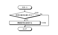
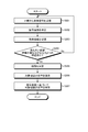
- FIG. 11 is a flowchart showing an example of the processing flow of the slave unit which is the target device according to the embodiment of the present disclosure.
- FIG. 12 is a flowchart showing an example of the flow of relay processing of the slave unit according to the embodiment of the present disclosure.
- FIG. 13 is a flowchart showing an example of a process flow in which the master unit according to the embodiment of the present disclosure specifies the position of the target device.
- FIG. 1 is a diagram for explaining a conventional wireless communication system.
- Wireless communication system 1 for example, the master receiver 2, the transmitter 3 1, the transmitter 3 2, a transmitter 3 3, and transmitter 3 4, a transmitter 35, transmitter 3 6, subject Including the device 4.
- Transmitters 3 1 to 3 6 are also collectively referred to as transmitters 3.
- Transmitters 3 1 transmitter 3 6 are each transmitter having a function of executing the communication using Bluetooth.
- Communicable range of the transmitters 3 1 is in the range R1.
- Communicable range of the transmitters 3 2 is in the range R2.
- the communicable range of the transmitter 3 3 is the range R3.
- Communicable range of the transmitters 3 4 is in the range R4.
- Communicatcable range of the transmitter 35 is in the range R5.
- Communicable range of the transmitters 3 6 is in the range R6.
- each transmitter is arranged so as to cover the entire predetermined range.
- the target device 4 is a communication device that executes short-range wireless communication.
- Target device 4 is, for example, among the transmitters 3 1 transmitter 3 6, the quality of communication is good, receives signals by Bluetooth from recognizable transmitter.
- target device 4 for example, receives signals by Bluetooth from a transmitter 3 3, and transmits such to the master receiver 2 position information in short-distance wireless communication.
- the wireless communication system 1 is a system that combines a Bluetooth transmitter and a short-range wireless communication system. Communication costs can be suppressed by combining a Bluetooth transmitter and a short-range wireless communication system.
- Bluetooth and short-range wireless communication are used, the occupancy of the wireless band becomes high and the cost of the equipment becomes relatively high.
- a wireless communication system capable of specifying the position of a specific target device is realized while configuring all the wireless devices with a short-range wireless communication device.
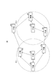
- FIG. 2 is a diagram for explaining a configuration of a wireless communication system according to the embodiment of the present disclosure.
- the radio communication system 10 includes a base unit 20, a handset 30 1, a handset 30 2, the handset 30 3, the handset 30 4, a handset 30 5, handset 30 6, and a slave unit 30 7.
- the wireless communication system 10 is a system constructed in, for example, a large shopping mall including a plurality of stores.
- handset 30 1 to handset 30 7 may be a communication device that is fixed mounted in place, it may be a mobile communication device. Also, by collectively handset 30 1 to handset 30 7, may be referred to as a handset 30.
- Wireless communication system 10 for example, a particular handset (e.g., handset 30 1 and handset 30 2) when the key is lost, a wireless communication system capable of identifying the position of the handset.
- a particular handset e.g., handset 30 1 and handset 30 2
- a wireless communication system capable of identifying the position of the handset.
- the target device to identify the position will be described with handset 30 1, the case where the handset 30 2 as an example.
- Communicable range of the short-range wireless handset 30 1 is in the range R11.
- Communicable range of the short-range wireless handset 30 2 is in the range R12.
- the slave unit 30 1 and the slave unit 30 2 broadcast a signal including at least their own identification information as transmission information to the range R11 and the range R12, respectively.
- the time information such as the time information and the time stamp unified by the system can be acquired in the handset to be transmitted
- the time information can be acquired.
- information on the transmission frequency, output power, transmission antenna gain, and reception antenna gain of the slave unit may be included in the transmission information.
- the master unit may be configured to perform position detection using a predetermined one. Further, if information on spatial propagation loss, loss due to surrounding buildings, etc.
- the predetermined condition means a condition for determining that the slave unit 30 1 and the slave unit 30 2 have been lost.
- the predetermined condition may be, for example, a case where the operation is not performed for a certain period of time or the ambient brightness does not change for a certain period of time.
- the predetermined condition is that when the slave unit 30 1 and the slave unit 30 2 are communication devices installed in a predetermined location, the conditions such as the ambient brightness and the loudness of the sound are different from those in the normal state. It may be the case.
- the predetermined condition may be a case where there is no movement for a certain period of time when the slave unit 30 1 and the slave unit 30 2 are mobile communication devices.
- the predetermined conditions are not limited to these, and may be other cases.
- the slave unit 30 3 , the slave unit 30 4, and the slave unit 30 6 are located within the range R11.
- the slave unit 30 3 , the slave unit 30 4, and the slave unit 30 6 receive a radio signal including transmission information transmitted by the slave unit 30 1. Determines that handset 30 3, the handset 30 4, the handset 30 6, respectively, the signal strength of the radio signal received from the slave unit 30 1.
- the outgoing information is updated by adding it to the outgoing information.
- the handset 30 3, the handset 30 4, handset 30 6 and each slave having received the radio signal outgoing includes signal strength to the calling information, and its own identification information, and time information
- the signal including the updated outgoing information is broadcast.
- the same process is repeated until the master unit 20 receives the wireless signal including the transmission information.
- the transmission path is looped, it becomes difficult to deliver the transmission information to the master unit, so it is determined whether or not the transmission information included in the received radio signal includes its own identification information. However, if it is included, it is advisable not to broadcast the signal including the updated transmission information.
- the base unit 20 In the R12 is a communication range of the mobile device 30 2, the base unit 20, it is arranged and the slave unit 30 7.
- the signal including the transmission information which handset 30 2 originates is received directly by the base unit 20.
- Handset 30 7 receives the signals from the handset 30 2 updates the transmission information, and transmits to the base unit 20.
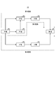
- FIG. 3 is a diagram for explaining a route from the target device to the master unit.
- Figure 3 shows a path from the handset 30 1 to the base device 20.
- the path from the handset 30 2 to the base device 20, and a description thereof will be omitted to perform the same processing.
- the calling information via the first path, and signal strength when receiving the radio signals from the handset 30 4 child machine 30 1, signal when receiving the radio signal from the slave unit 30 5 child machine 30 4 Includes strength.
- the transmission information via the second path includes the signal strength when the slave unit 30 3 receives the radio signal from the slave unit 30 1 and the signal when the slave unit 30 4 receives the radio signal from the slave unit 30 3. and strength, include signal strength when receiving the radio signal from the slave unit 30 5 child machine 30 4.
- the calling information via the third path, and signal strength when receiving the radio signals from the handset 30 6 child machine 30 1, signal when receiving the radio signals from the handset 30 7 child machine 30 6 Includes strength.
- the master unit 20 acquires the signal strength of the radio signal received by each slave unit existing on each path.
- the master unit 20 adds the signal strength determined when received from the slave unit, its own identification information, and the time information to the transmission information included in the received wireless signal, thereby transmitting the transmission information. May be configured to update. If the transmission information configured in this way is configured so that the master unit 20 can accumulate the transmission information, the configuration is even better.
- FIG. 4 is a diagram for explaining transmission information included in the signal received by the master unit.
- the "route name”, the “route”, the “first signal strength”, the “second signal strength”, and the “third signal strength” are used. It may be managed by items such as.
- the "route name” is information for identifying the route.
- the "route name” may be, for example, information such as a first route, a second route, and a third route. Further, the route name may be managed by the index number.
- Root is the information about the child machine via up to the master unit from the slave unit 30 1.
- the handset 30 4 may it is shown that via the handset 30 5.
- the handset 30 3 may the handset 30 4, when it is shown that via the handset 30 5.
- the handset 30 6 may it is shown that via the handset 30 7.
- Information on this route may be indicated by identifying the slave unit name from the slave unit identification information.
- the first signal strength in terms of the first path, the signal strength at the time of receiving the radio signals from the handset 30 4 child machine 30 1 is shown.
- the first signal strength in terms of the second path, the signal strength at the time of receiving the radio signals from the handset 30 3 child machine 30 1 is shown.
- the first signal strength in terms of the third path, the signal strength at the time of receiving the radio signals from the handset 30 6 child machine 30 1 is shown. Specifically, the “first signal strength” is "3/10" in the first path.
- “Second signal strength” in terms of the first path the signal strength upon reception of a radio signal from the slave unit 30 5 child machine 30 4 is shown.
- “Second signal strength” in terms of the second path the signal strength at the time of receiving the radio signals from the handset 30 4 child machine 30 3 is shown.
- “Second signal strength” in terms of the third path the signal strength at the time of receiving the radio signals from the handset 30 7 child machine 30 6 is shown.
- the “second signal strength” is "6/10" in the first path.
- “Third signal strength” in terms of the second path the signal strength when a signal is received from the child device 30 5 child machine 30 4 is shown. Specifically, the “third signal strength” is “6/10" in the second path. In the first path and the second path, the transmission information reaches the master unit 20 via the two slave units, so that the signal strength is not included.
- the "first signal strength” to “third signal strength” are shown in 10 steps of “1/10” to “10/10", respectively, but the present invention is not limited to this. ..
- the signal strength may be shown in more than a few steps or in decibels.
- the signal strength may be configured to be indicated by a value using dBm, which is a decibel unit based on 1 mW, or dB ⁇ , which is based on 1 ⁇ V.
- Base unit 20 based on the transmission information received from each child device, to locate the handset 30 1 is the target device.
- the position may be specified by using the Fris transmission formula to specify the distance.
- the distance is specified by using information on the transmission frequency, output power, transmission antenna gain, reception antenna gain, spatial propagation loss, loss due to surrounding buildings, etc. of the slave unit. Then, it becomes possible to specify the position with higher accuracy. For example, in the case of decibel units, the received input power is equal to the output power, the transmitting antenna gain, and the receiving antenna gain, and the free space propagation loss and the loss due to surrounding buildings, etc. are subtracted. You may find the distance.
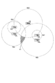
- FIG. 5 is a diagram for explaining a method in which the master unit identifies the position of the target device.
- the master unit 20 shown in FIG., The first path, based on the transmission information of the third path, a method for identifying the position of the mobile device 30 1.
- Base unit 20 determines the first path, when receiving a radio signal including a transmission information from the child device 30 5, the signal strength of the signal.
- the master unit 20 specifies the distance to the slave unit that transmits the wireless signal based on the signal strength of the wireless signal acquired by the master unit or the slave unit on the route, and the specified distance is the radius of the circle.
- the position of the slave unit is specified assuming that the slave unit exists within the range.
- base unit 20 is, for example, based on the signal strength of the radio signals, the handset 30 5 identifies that was located in a range within R20.
- base unit 20, in the third path handset 30 7 identifies that was located in a range within R20.
- the base unit 20 the signal strength from the handset 30 5 and the slave unit 30 7, has been described as being equivalent. If the signal strength of the mobile device 30 5 and the slave device 30 7 are different, within a distance of different radii of the circle from the base unit 20, it will include the respective slave unit.
- the base device 20 in the first path based on the transmission information included in the radio signal received from the slave unit 30 5, to locate the handset 30 4.
- the base device 20, "the second signal strength” is based on a "6/10", the handset 30 4 identifies that was located within the range R25.
- base unit 20, in the third path “second signal strength” is based on a "7/10", the handset 30 6 identifies that was located within the range R27.
- the base device 20 in the first path based on the transmission information included in the radio signal received from the slave unit 30 5, to locate the handset 30 1.
- the master unit 20 estimates that the slave unit 30 1 was located within the range R24 based on the fact that the “first signal strength” is “3/10”.
- the master unit 20 estimates that the slave unit 30 1 was located within the range R26 based on the fact that the “first signal strength” is “1/10” in the third path.
- Base unit 20 includes a range R24 estimated on the basis of the first path, when the common area of the range R26 estimated based on the third path handset 30 1 specified as being a region located Good. Further, as shown in Figure 5, further, the common area between the ranges R24 and scope R26, and given that the signal strength of the base device 20 the slave unit 30 5 and the slave device 30 7 is equal, The area A1 excluding the specified range R20 may be specified as the area where the slave unit 30 1 is located. The area excluded as the distance from the base unit 20, a distance which is specified from the signal strength of the mobile device 30 1 to the range of a circle whose radius may be excluded areas. Thus, base unit 20 can be based on two paths, it is possible to accurately identify the location of the mobile device 30 1.
- the base device 20 in addition to the handset 30 5 and handset 30 7 receives the signals from the handset 30 8, based on the three paths, the position of the mobile device 30 1 May be specified.
- the master unit 20 specifies that the slave unit 30 1 is located in the common region A2 of the range R21A, the range R21B, and the range R21C. As the number of routes from the slave unit 30 1 to the master unit 20 increases, the area to be specified becomes narrower, so that the master unit 20 can specify the position of the slave unit 30 1 more accurately.
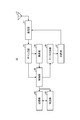
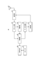
- FIG. 7 is a block diagram showing an example of the configuration of the master unit according to the embodiment of the present disclosure.
- the master unit 20 includes an antenna 41, a communication unit 42, a gain circuit 43, a demodulation unit 44, a control unit 45, a data addition unit 46, a modulation unit 47, and a storage unit 48. And a specific unit 49.
- the communication unit 42 receives various wireless signals from the outside via the antenna 41.
- the communication unit 42 receives, for example, a radio signal including transmission information from each slave unit via the antenna 41.
- the communication unit 42 transmits various signals to the outside via the antenna 41.
- the communication unit 42 outputs the received radio signal to the gain circuit 43.
- the gain circuit 43 detects the signal strength of the radio signal received from the communication unit 42.
- the gain circuit 43 outputs information regarding the detected signal strength to the control unit 45.
- the gain circuit 43 amplifies the signal received from the communication unit 42 at a predetermined amplification factor.
- the gain circuit 43 outputs the amplified signal to the demodulation unit 44.
- the demodulation unit 44 demodulates the signal received from the gain circuit 43. Specifically, the demodulation unit 44 demodulates the signal received from the gain circuit 43 and converts it into a digital data string. The demodulation unit 44 outputs the demodulated signal to the control unit 45.
- the control unit 45 is a controller that controls the entire master unit 20.
- the control unit 45 is realized by, for example, a processor such as a CPU (Central Processing Unit) or an MPU (Micro Processing Unit).
- the control unit 45 is realized by the processor executing various programs stored in the storage device of the master unit 20 using a RAM (Random Access Memory) or the like as a work area.
- the control unit 45 may be realized by an integrated circuit such as an ASIC (Application Specific Integrated Circuit) or an FPGA (Field Programmable Gate Array).
- the control unit 45 acquires information on the signal strength received from the slave unit from the gain circuit 43.
- the control unit 45 outputs the acquired information on the signal strength to the specific unit 49.
- the control unit 45 acquires transmission information of each slave unit that has passed from the demodulation unit 44 until the signal reaches the master unit 20 from the target device.
- the control unit 45 stores the acquired transmission information in the storage unit 48.
- the control unit 45 acquires various information for transmission to the outside from the storage unit 48.
- the control unit 45 outputs various information acquired from the storage unit 48 to the data addition unit 46.
- the data addition unit 46 adds various data to the voice signal or instruction signal transmitted to the outside by the master unit 20, and outputs the data to the modulation unit 47, for example.
- the data addition unit 46 does not necessarily have to add data to the voice signal or instruction signal transmitted by the master unit 20 to the outside.
- the modulation unit 47 modulates the signal received from the data addition unit 46. Specifically, the modulation unit 47 digitally modulates the signal received from the data addition unit 46. The signal modulated by the modulation unit 47 is transmitted to the outside by the communication unit 42 via the antenna 41.
- the storage unit 48 stores various types of information.
- the storage unit 48 stores the transmission information transmitted from the slave unit. Specifically, the storage unit 48 stores transmission information for each route.
- the storage unit 48 can be realized by, for example, a semiconductor memory element such as a RAM (Random Access Memory) or a flash memory (Flash Memory), or a storage device such as a hard disk or a solid state drive.
- the specific unit 49 specifies various types of information.
- the identification unit 49 identifies various types of information based on the transmission information stored in the storage unit 48. For example, the identification unit 49 identifies at least two routes having different oldest route information among the routes from the target device to the master unit 20 via the plurality of slave units based on the transmission information.
- the identification unit 49 identifies the position of each slave unit and the position of the target device, for example, based on the signal strength included in the transmission information in at least two routes having different oldest route information.
- the specifying unit 49 may specify at least two routes from the target device to the master unit 20 via the plurality of slave units, in which the routes from the target device to the master unit 20 are all different. In this case, the specifying unit 49 identifies the position of each slave unit and the position of the target device based on the transmission information in at least two routes in which the routes from the target device to the master unit 20 are all different.
- FIG. 8 is a block diagram showing an example of the configuration of the slave unit according to the embodiment of the present disclosure.
- the slave unit 30 includes an antenna 51, a communication unit 52, a gain circuit 53, a demodulation unit 54, a control unit 55, a data addition unit 56, a modulation unit 57, and a voice AMP ( The amplifier) 58 and the speaker 59 are provided.
- the antenna 51, the communication unit 52, the gain circuit 53, and the demodulation unit 54 are the same as the antenna 41, the communication unit 42, the gain circuit 43, and the demodulation unit 44 shown in FIG. 7, respectively, and thus the description thereof will be omitted.
- the control unit 55 acquires information on the signal strength received from the slave unit from the gain circuit 53.
- the control unit 55 outputs information on the signal strength to the data addition unit 56.
- the control unit 55 acquires transmission information of each slave unit that has passed from the demodulation unit 44 until the signal reaches the master unit 20 from the target device.
- the control unit 55 outputs the acquired transmission information to the data addition unit 56.
- the control unit 55 acquires a voice signal related to voice from the demodulation unit 44
- the control unit 55 outputs the voice signal to the voice AMP 58.
- the control unit 55 may determine that the user has lost the slave unit 30 based on the measurement result of, for example, a sensor (not shown). Specifically, the control unit 55 determines that there is no change in the ambient brightness for a certain period of time, or that the ambient brightness, loudness, and other conditions are different from the normal conditions, based on the measurement results of the sensor. If this is the case, it may be determined that the slave unit 30 has been lost. Further, when the control unit 55 determines that the slave unit 30 has been lost, the control unit 55 may emit a sound from the speaker 59 or emit a display unit or an LED (Light Emitting Diode) (not shown).
- LED Light Emitting Diode
- the data addition unit 56 updates the transmission information by adding its own identification information, time information, and information on the reception strength received from the control unit 55 to the transmission information received from the control unit 55.
- the data addition unit 56 outputs the updated transmission information to the modulation unit 57.
- the modulation unit 57 modulates the updated transmission information received from the data addition unit 56.
- the signal including the transmission information modulated by the modulation unit 47 is transmitted to the outside by the communication unit 52 via the antenna 51.
- the voice AMP 58 When the voice AMP 58 receives the voice signal from the control unit 55, the voice AMP 58 amplifies the voice signal.
- the speaker 59 outputs a voice signal amplified by the voice AMP 58 as voice.
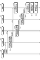
- FIG. 9 is a diagram for explaining the processing of the wireless communication system according to the embodiment of the present disclosure.
- FIG. 10 is a sequence diagram showing a processing flow of the wireless communication system according to the embodiment of the present disclosure.
- the radio communication system 10A includes a base unit 20, a handset 30 1, a handset 30 2, the handset 30 3, and a handset 30 4.
- the slave unit 30 1 is the target device. In reaches the master unit 20 via a path that reaches the base unit 20 via the handset 30 1 slave unit 30 2, and a handset 30 1 child machine 30 3 and the slave device 30 4 or less It will be described flow of processing for specifying a location of the mobile device 30 1 on the basis of the path.
- the slave unit 30 1 transmits a radio signal including transmission information, and the slave unit 30 2 receives the signal (step S11). At the same receiving signals in parallel also handset 30 3 simultaneously (step S12).
- the slave unit 30 2 When the slave unit 30 2 receives the radio signal from the slave unit 30 1 , the slave unit 30 2 updates the transmission information by adding the signal strength, the time information, and its own identification information to the transmission information included in the radio signal (the transmission information). Step S13). Handset 30 2 transmits a radio signal including a calling information updated in the master unit 20 (step S14).
- the master unit 20 stores information on the route from the slave unit 30 1 to the master unit 20 and the signal strength based on the updated transmission information (step S15).
- the slave unit 30 3 When the slave unit 30 3 receives the radio signal from the slave unit 30 1 , the slave unit 30 3 updates the transmission information by adding the signal strength, the time information, and its own identification information to the transmission information included in the radio signal (the transmission information). Step S16). The slave unit 30 3 transmits a radio signal including the updated transmission information to the slave unit 30 4 (step S17).
- the slave unit 30 4 When the slave unit 30 4 receives the radio signal from the slave unit 30 3 , the slave unit 30 4 updates the transmission information by adding the signal strength, the time information, and its own identification information to the transmission information included in the radio signal (the transmission information). Step S18). Handset 30 4 transmits a radio signal including a calling information updated in the master unit 20 (step S19).
- the master unit 20 stores information on the route from the slave unit 30 1 to the master unit 20 and the signal strength based on the updated transmission information (step S20).
- the master unit 20 identifies at least two routes with different oldest route information among the routes that arrived at the master unit 20 from the target device via each slave unit (step S21).
- Base unit 20 based on the signal intensity included in the transmission information about the two paths to locate the handset 30 1 a target device (step S22). Then, the process of FIG. 10 is completed.
- FIG. 11 is a flowchart showing an example of the processing flow of the slave unit which is the target device according to the embodiment of the present disclosure.
- the slave unit 30 determines whether or not a predetermined condition is satisfied (step S101).
- the predetermined condition is a condition in which the control unit 55 determines that the slave unit 30 has been lost. If it is determined that the predetermined condition is satisfied (Yes in step S101), the process proceeds to step S102. On the other hand, when it is determined that the predetermined condition is not satisfied (No in step S101), the process of FIG. 11 is terminated.
- step S101 the slave unit 30 transmits a wireless signal (step S102). Specifically, the slave unit 30 broadcasts a radio signal including transmission information by the communication unit 52. Then, the process of FIG. 11 is completed.
- FIG. 12 is a flowchart showing an example of the flow of relay processing of the slave unit according to the embodiment of the present disclosure.
- the slave unit 30 determines whether or not a radio signal has been received from another slave unit (step S201). Specifically, the communication unit 52 determines whether or not a radio signal including transmission information has been received from another slave unit. If it is determined that the radio signal has been received (Yes in step S201), the process proceeds to step S202. If it is determined that the radio signal has not been received (No in step S201), the process of step S201 is repeated.
- step S201 the slave unit 30 determines the signal strength of the received radio signal (step S202). Specifically, the gain circuit 53 determines the signal strength of the received radio signal. Then, the process proceeds to step S203.
- the slave unit 30 updates the transmission information by adding the signal strength of the received radio signal, its own identification information, and the time information to the transmission information included in the received radio signal (step S203).
- the data addition unit 56 updates the transmission information by adding the signal strength of the received radio signal, its own identification information, and the time information to the transmission information included in the received radio signal. Then, the process proceeds to step S204.
- the slave unit 30 transmits a wireless signal including transmission information (step S204). Specifically, the communication unit 52 broadcasts a radio signal including the transmission information updated in step S203. Then, the process of FIG. 12 is completed.
- FIG. 13 is a flowchart showing an example of a process flow in which the master unit according to the embodiment of the present disclosure specifies the position of the target device.
- the master unit 20 receives a wireless signal from each slave unit (step S301). Specifically, the communication unit 42 receives a wireless signal including transmission information from each slave unit. Then, the process proceeds to step S302.
- the master unit 20 determines the signal strength of the received wireless signal (step S302). Specifically, the gain circuit 43 determines the signal strength of the radio signal received in step S301. Then, the process proceeds to step S303.
- the master unit 20 stores the transmission information included in the wireless signal (step S303). Specifically, the control unit 45 stores the transmission information included in the radio signal received in step S301 in the storage unit 48. Then, the process proceeds to step S304.
- the master unit 20 determines whether or not there are at least two routes having different oldest route information among the routes from the target device to the master unit 20 (step S304). Specifically, the specific unit 49 determines whether or not there are at least two routes having different oldest route information based on the transmission information stored in the storage unit 48. If it is determined that there are at least two routes with different oldest route information (Yes in step S304), the process proceeds to step S305. On the other hand, if it is determined that there are at least two routes with different oldest route information (No in step S304), the process proceeds to step S301.
- step S304 the master unit 20 determines the route (step S305). Specifically, the identification unit 49 determines two or more routes having different oldest route information in order to specify the position of the target device. Then, the process proceeds to step S306.
- the master unit 20 estimates the position of the target device (step S306). Specifically, the specific unit 49 estimates the position of the target device based on the route determined in step S305. Then, the process proceeds to step S307.
- the master unit 20 specifies the position of the target device based on the signal strength (step S307). Specifically, the identification unit 49 specifies the position of the target device based on the signal strength of each slave unit with respect to the route determined in step S305. Then, the process of FIG. 13 is completed.
- the position of a specific target device can be specified using only short-range wireless communication.
- the accuracy of specifying the position of the target device can be improved by receiving the radio signal from the target device with a plurality of receivers.
- the position of the target device can be specified only by short-range wireless communication, the cost can be suppressed.
- the present disclosure is not limited by the contents of these embodiments.
- the above-mentioned components include those that can be easily assumed by those skilled in the art, those that are substantially the same, that is, those having a so-called equal range.
- the components described above can be combined as appropriate. Further, various omissions, replacements or changes of the components can be made without departing from the gist of the above-described embodiment.
- the wireless communication system and communication method of the present embodiment can be used, for example, in a communication device having a short-range wireless communication function.
Landscapes
- Engineering & Computer Science (AREA)
- Computer Networks & Wireless Communication (AREA)
- Signal Processing (AREA)
- Physics & Mathematics (AREA)
- General Physics & Mathematics (AREA)
- Radar, Positioning & Navigation (AREA)
- Remote Sensing (AREA)
- Mobile Radio Communication Systems (AREA)
Abstract
無線通信システムは、対象機器を含む複数の中継通信装置(30)と、通信装置(20)とを含む。複数の中継通信装置(30)は、対象機器および他の中継通信装置から受信した発信情報を含む無線信号に基づいて、無線信号の信号強度に関する信号強度情報を取得する第1制御部(55)と、信号強度情報と、時刻情報と、自身の識別情報とを発信情報に付加して、発信情報を更新するデータ付加部(56)と、更新された前記発信情報をブロードキャストする通信部(52)と、を備える。通信装置(20)は、更新された発信情報を取得する第2制御部(45)と、複数の中継通信装置から受信した無線信号に含まれる更新された発信情報に基づいて特定された最も古い経路情報が異なる少なくとも2つの経路に基づいて、対象機器の位置を特定する特定部(49)を備える。
Description
本開示は、無線通信システムおよび通信方法に関する。
GPS(Global Positioning System)や、Bluetooth(登録商標)を用いた通信を行う機能を持つ発信機を固定位置に配置し、その発信機からの信号を受信することで自身の位置を特定する技術が知られている。
例えば、特許文献1には、GPS信号に基づいて、自車両の位置を検出する技術が記載されている。
しかしながら、GPSは位置を直接検出できるものの屋内では利用することができない。また、自身の位置を特定するために、自身の端末は、Bluetoothによる親機である必要がある。具体的には、親機は、信号を受信したら、予め保持されている各発信機の位置情報から自分の位置を特定し、特定した情報を携帯電話回線またはWi-Fi(登録商標)回線を利用して、定められた場所に送信する必要がある。そのため、例えば、比較的広い屋内エリアなどで遠隔の決められた場所から、特定の対象物の位置を特定するには通信コストの制約と、通信設備の制約により不向きである可能性が高い。
本開示は、対象物の位置を容易に特定することのできる無線通信システムおよび通信方法を提供することを目的とする。
本開示の一態様の無線通信システムは、対象機器を含む複数の中継通信装置と、通信装置とを含み、複数の前記中継通信装置は、前記対象機器および他の中継通信装置から受信した発信情報を含む無線信号に基づいて、前記無線信号の信号強度に関する信号強度情報を取得する第1制御部と、前記信号強度情報と、時刻情報と、自身の識別情報とを前記発信情報に付加して、発信情報を更新するデータ付加部と、更新された前記発信情報をブロードキャストする通信部と、を備え、前記通信装置は、更新された前記発信情報を取得する第2制御部と、複数の前記中継通信装置から受信した前記無線信号に含まれる更新された前記発信情報に基づいて特定された最も古い経路情報が異なる少なくとも2つの経路に基づいて、前記対象機器の位置を特定する特定部を備える。
本開示の一態様の通信方法は、対象機器を含む複数の中継通信装置と、通信装置とを含む無線通信システムの通信方法であって、前記対象機器および他の中継通信装置から受信した発信情報を含む無線信号に基づいて、前記無線信号の信号強度に関する信号強度情報を取得するステップと、前記信号強度情報と、時刻情報と、自身の識別情報とを前記発信情報に付加して、発信情報を更新するステップと、更新された前記発信情報をブロードキャストするステップと、更新された前記発信情報を取得するステップと、複数の前記中継通信装置から受信した前記無線信号に含まれる更新された前記発信情報に基づいて特定された最も古い経路情報が異なる少なくとも2つの経路に基づいて、前記対象機器の位置を特定するステップと、を含む。
本開示によれば、対象物の位置を容易に特定することができる。
以下、添付図面を参照して、本開示に係る実施形態を詳細に説明する。なお、この実施形態により本開示が限定されるものではなく、また、実施形態が複数ある場合には、各実施形態を組み合わせて構成するものも含む。また、以下の実施形態において、同一の部位には同一の符号を付することにより重複する説明を省略する。
[従来技術]
まず、本開示の理解を容易にするために、図1を用いて、対象物の位置を検出するための従来の無線通信システムについて説明する。図1は、従来の無線通信システムを説明するための図である。
まず、本開示の理解を容易にするために、図1を用いて、対象物の位置を検出するための従来の無線通信システムについて説明する。図1は、従来の無線通信システムを説明するための図である。
無線通信システム1は、例えば、親受信機2と、発信機31と、発信機32と、発信機33と、発信機34と、発信機35と、発信機36、対象機器4とを含む。発信機31~発信機36を総称して、発信機3と呼ぶこともある。
発信機31~発信機36は、それぞれ、Bluetoothを用いた通信を実行する機能を有する発信機である。発信機31の通信可能範囲は、範囲R1である。発信機32の通信可能範囲は、範囲R2である。発信機33の通信可能範囲は、範囲R3である。発信機34の通信可能範囲は、範囲R4である。発信機35の通信可能範囲は、範囲R5である。発信機36の通信可能範囲は、範囲R6である。具体的には、無線通信システム1では、所定範囲の全てをカバーするように各発信機は配置されている。
対象機器4は、近距離無線通信を実行する通信機器である。対象機器4は、例えば、発信機31~発信機36のうち、通信の品質が良く、認識可能な発信機からBluetoothによる信号を受信する。図1に示す例では、対象機器4は、例えば、発信機33からBluetoothによる信号を受信し、近距離無線通信で位置情報などを親受信機2に送信する。
このように、無線通信システム1は、Bluetooth発信機と、近距離無線通信システムを組み合わせたシステムである。Bluetooth発信機と、近距離無線通信システムを組み合わせることで、通信コストを抑制することができる。しかしながら、Bluetoothと近距離無線通信との2つの無線通信を用いているため、無線帯域の占有度が高くなり、かつ設備のコストが比較的高くなってしまう。また、位置を特定するための情報としてBluetoothを使用する場合、位置精度を高めたり、広い範囲をカバーしたりするためには、多くの発信機をユーザの邪魔とならない場所に設置することが必要になる。そのため、コストが増加したり、設置する場所が制限されたりする課題が生じていた。
そこで、本実施形態では、全ての無線機を近距離無線通信装置で構成しつつ、特定の対象機器の位置を特定できるような無線通信システムを実現する。
[実施形態]
図2を用いて、本開示の実施形態に係る無線通信システムの構成について説明する。図2は、本開示の実施形態に係る無線通信システムの構成を説明するための図である。
図2を用いて、本開示の実施形態に係る無線通信システムの構成について説明する。図2は、本開示の実施形態に係る無線通信システムの構成を説明するための図である。
図2に示すように、無線通信システム10は、親機20と、子機301と、子機302と、子機303と、子機304と、子機305と、子機306と、子機307とを含む。無線通信システム10は、例えば、複数の店舗を含む大型のショッピングモールなどに構築されるシステムである。親機20と、子機301~子機307とは、近距離無線通信を実行する機能を有する通信装置である。親機20と、子機301~子機307の近距離無線による通信範囲は、例えば、数10~200m程度であるが、これに限定されない。なお、子機301~子機307は、所定の場所に取り付けられて固定されている通信装置であってもよいし、モバイル型の通信装置であってもよい。また、子機301~子機307を総称して、子機30と呼ぶこともある。
無線通信システム10は、例えば、特定の子機(例えば、子機301や子機302)を紛失してしまった場合に、その子機の位置を特定することのできる無線通信システムである。以下では、位置を特定する対象機器が、子機301と、子機302である場合を例に説明する。
子機301の近距離無線による通信可能範囲は、範囲R11である。子機302の近距離無線による通信可能範囲は、範囲R12である。
子機301および子機302は、それぞれ、所定の条件を満たした場合に、範囲R11および範囲R12に対して少なくとも自身の識別情報を発信情報として含む信号をブロードキャストする。ここで、発信する子機において時間情報やシステムで統一管理しているタイムスタンプなどの時刻情報を取得できる場合には、発信情報に時刻情報を含めるとよい。以下、時刻情報は取得できるものとして説明する。また、子機の送信周波数、出力電力、送信アンテナ利得、受信アンテナ利得に関する情報を、発信情報に含めてもよい。発信する子機において、上述の情報が取得できない場合、親機は、所定のものを利用して位置検出を行うように構成してもよい。更に、子機の周囲の環境情報として、空間伝搬損失、周囲の建物等による損失に関する情報が取得できる場合には、発信情報に含めてもよい。上述の情報が発信情報に含まれることにより、親機による、精度の高い位置検出が可能になる。所定の条件とは、子機301および子機302を紛失したと判定される条件のことをいう。所定の条件は、例えば、一定期間操作されなかったり、一定期間周囲の明るさに変化がなかったりする場合であってよい。また、所定の条件は、子機301および子機302が所定の場所に取り付けられている通信装置である場合には、周囲の明るさや、音の大きさなどの状況が通常時と異なる場合であってよい。また、所定の条件は、子機301および子機302がモバイル型の通信装置である場合には、一定期間動きが無かった場合であってよい。所定の条件は、これらに限定されず、その他の場合であってもよい。
子機303と、子機304と、子機306とは、範囲R11内に位置している。子機303と、子機304と、子機306とは、子機301が発信した発信情報を含む無線信号を受信する。子機303と、子機304と、子機306とは、それぞれ、子機301から受信した無線信号の信号強度を判定する。子機と303と、子機304と、子機306とは、それぞれ、判定された信号強度と、自身の識別情報と、時刻情報とを子機301から受信した無線信号に含まれる発信情報に付加することで、発信情報を更新する。子機303と、子機304と、子機306とは、それぞれ、更新した発信情報を含む信号をブロードキャストする。以後、子機303と、子機304と、子機306とが発信した無線信号を受信した各子機は、発信情報に信号強度と、自身の識別情報と、時刻情報とを付加して更新した後、更新した発信情報を含む信号をブロードキャストする。無線通信システム10では、同様の処理を親機20が発信情報を含む無線信号を受信するまで繰り返す。これにより、子機301からの発信情報は、複数の経路を経由して、親機20に到達する。すなわち、各子機は、中継通信装置として機能する。ここで、伝送経路がループしていると、親機に発信情報を届けることが困難になるため、受信した無線信号に含まれる発信情報に、自身の識別情報が含まれているか否かを判定し、含まれている場合には、更新した発信情報を含む信号のブロードキャストを行わないようにするとよい。
子機302の通信範囲であるR12内には、親機20と、子機307とが配置されている。この場合、子機302が発信する発信情報を含む信号は、親機20によって直接受信される。子機307は、子機302から信号を受信すると、発信情報を更新して、親機20に送信する。
図3を用いて、対象機器から親機までの経路について説明する。図3は、対象機器から親機までの経路を説明するための図である。
図3は、子機301から親機20までの経路を示している。子機302から親機20までの経路については、同様の処理を実行するため説明を省略する。
図3に示すように、子機301からの発信情報は、第1経路として、子機304と、子機305とを順に経由して親機20に到達する。子機301からの発信情報は、第2経路として、子機303と、子機304と、子機305とを順に経由して親機20に到達する。子機301からの発信情報は、第3経路として、子機306と、子機307とを順に経由して親機20に到達する。
第1経路を経由した発信情報には、子機304が子機301から無線信号を受信した際の信号強度と、子機305が子機304から無線信号を受信した際の信号強度とが含まれる。第2経路を経由した発信情報には、子機303が子機301から無線信号を受信した際の信号強度と、子機304が子機303から無線信号を受信した際の信号強度と、子機305が子機304から無線信号を受信した際の信号強度が含まれる。第3経路を経由した発信情報には、子機306が子機301から無線信号を受信した際の信号強度と、子機307が子機306から無線信号を受信した際の信号強度とが含まれる。言い換えれば、親機20は、各経路上に存在する各子機が受信した無線信号の信号強度を取得する。また、親機20は、子機から受信した際に、判定された信号強度と、自身の識別情報と、時刻情報とを、受信した無線信号に含まれる発信情報に付加することで、発信情報を更新するように構成してもよい。このように構成した発信情報を、親機20が蓄積できるように構成すると、更によい構成となる。
図4を用いて、親機が受信する信号に含まれる発信情報について説明する。図4は、親機が受信する信号に含まれる発信情報を説明するための図である。
図4に示すように、親機において発信情報を管理する際に、「経路名」と、「ルート」と、「第1信号強度」と、「第2信号強度」と、「第3信号強度」といった項目により管理してもよい。
「経路名」は、経路を識別するための情報である。「経路名」は、例えば、第1経路、第2経路、第3経路といった情報であればよい。また、経路名をインデックス番号によって管理するようにしてもよい。
「ルート」は、子機301から親機までに経由した子機に関する情報である。第1経路で言えば、子機304と、子機305とを経由したことが示されるとよい。第2経路で言えば、子機303と、子機304と、子機305とを経由したことが示されるとよい。第3経路で言えば、子機306と、子機307とを経由したことが示されるとよい。このルートに関する情報は、子機の識別情報から子機名を特定し、示されるとよい。
「第1信号強度」は、第1経路で言えば、子機304が子機301から無線信号を受信した際の信号強度が示される。「第1信号強度」は、第2経路で言えば、子機303が子機301から無線信号を受信した際の信号強度が示される。「第1信号強度」は、第3経路で言えば、子機306が子機301から無線信号を受信した際の信号強度が示される。具体的には、「第1信号強度」は、第1経路で言えば、「3/10」である。
「第2信号強度」は、第1経路で言えば、子機305が子機304から無線信号を受信した際の信号強度が示される。「第2信号強度」は、第2経路で言えば、子機304が子機303から無線信号を受信した際の信号強度が示される。「第2信号強度」は、第3経路で言えば、子機307が子機306から無線信号を受信した際の信号強度が示される。具体的には、「第2信号強度」は、第1経路で言えば、「6/10」である。
「第3信号強度」は、第2経路で言えば、子機305が子機304から信号を受信した際の信号強度が示される。具体的には、「第3信号強度」は、第2経路で言えば、「6/10」である。なお、第1経路と、第2経路とでは、発信情報は、2つの子機を経由して、親機20に到達するため、信号強度は含まれていない。
なお、図4に示す例では、「第1信号強度」~「第3信号強度」は、それぞれ、「1/10」~「10/10」の10段階で示しているが、これに限定されない。本実施形態では、例えば、信号強度は、更に多くの複数の段階で示してもよいし、デシベル単位で示してもよい。特に、信号強度を、1mWを基準にしたデシベル単位であるdBmや1μVを基準にしたdBμを用いた値で示すように構成するとよい。
親機20は、各子機から受信した発信情報に基づいて、対象機器である子機301の位置を特定する。例えば、位置の特定に、フリスの伝達公式を利用して、距離を特定するように構成してもよい。また、利用可能であれば、子機の送信周波数、出力電力、送信アンテナ利得、受信アンテナ利得に関する情報、空間伝搬損失、周囲の建物等による損失に関する情報を利用して距離を特定するように構成すると、更に精度の高い位置の特定が可能になる。例えば、デシベル単位である場合に、受信入力電力は、出力電力と送信アンテナ利得と受信アンテナ利得を加算し、自由空間伝搬損失と周囲の建物等などによる損失を減算したものと等しいという関係を利用して距離を求めてもよい。親機20は、例えば、最も古い経路情報が異なる少なくとも2つの経路から受信した発信情報に基づいて、子機301の位置を特定する。ここで、最も古い経路情報が異なるとは、子機301からの発信情報を受信した子機が異なることを意味する。
図5を用いて、親機が対象機器の位置を特定する方法について説明する。図5は、親機が対象機器の位置を特定する方法を説明するための図である。
図5では、親機20は、図に示す、第1経路と、第3経路との発信情報に基づいて、子機301の位置を特定する方法について説明する。
親機20は、第1経路において、子機305から発信情報を含む無線信号を受信すると、その信号の信号強度を判定する。親機20は、経路上の親機、もしくは子機によって取得する無線信号の信号強度に基づいて、無線信号を発信した子機までの距離を特定し、特定された距離を半径とする円の範囲内に、子機が存在するものとして、子機の位置を特定する。子機305の位置を特定する場合において、親機20は、例えば、無線信号の信号強度に基づいて、子機305は範囲R20内に位置していたことを特定する。同様に、親機20は、第3経路において、子機307は、範囲R20内に位置していたことを特定する。ここで、図5では説明を簡単にするために、親機20において、子機305と子機307からの信号強度が、同等であるものとして説明している。子機305と子機307の信号強度が異なる場合には、親機20からの距離が異なる半径の円の範囲内に、それぞれの子機が含まれることになる。
親機20は、第1経路において、子機305から受信した無線信号に含まれる発信情報に基づいて、子機304の位置を特定する。親機20は、「第2信号強度」に基づいて、子機304の位置を特定する。親機20は、「第2信号強度」が「6/10」であることに基づいて、子機304は範囲R25内に位置していたことを特定する。同様に、親機20は、第3経路において、「第2信号強度」が「7/10」であることに基づいて、子機306は範囲R27内に位置していたことを特定する。
親機20は、第1経路において、子機305から受信した無線信号に含まれる発信情報に基づいて、子機301の位置を特定する。親機20は、「第1信号強度」に基づいて、子機301の位置を推定する。親機20は、「第1信号強度」が「3/10」であることに基づいて、子機301は範囲R24内に位置していたことを推定する。同様に、親機20は、第3経路において、「第1信号強度」が「1/10」であることに基づいて、子機301は範囲R26内に位置していたことを推定する。
親機20は、第1経路に基づいて推定された範囲R24と、第3経路に基づいて推定された範囲R26との共通の領域を子機301が位置している領域であると特定するとよい。また、図5で示されるように、更に、範囲R24と範囲R26との共通の領域から、親機20から子機305と子機307の信号強度が、同等であることを踏まえて、特定される範囲R20を除外した領域A1を、子機301が位置している領域であると特定してもよい。また、親機20からの距離として除外する領域は、子機301の信号強度から特定された距離を半径とする円の範囲を、除外する領域としてもよい。このように、親機20は、2つの経路に基づくことで、子機301の位置を精度よく特定することができる。
図5では、2つの経路に基づいて子機301の位置を特定する方法を説明したが、本開示はこれに限られない。
例えば、図6に示すように、親機20は、子機305および子機307に加えて、子機308から信号を受信し、3つの経路に基づいて、子機301の位置を特定してもよい。この場合、親機20は、範囲R21Aと、範囲R21Bと、範囲R21Cとの共通の領域A2に子機301が位置している領域であると特定する。子機301から親機20まで経路が増えるに連れて特定される領域が狭くなるので、親機20は、より精度よく子機301の位置を特定することができるようになる。
[親機の構成]
図7を用いて、本開示の実施形態に係る親機の構成を説明する。図7は、本開示の実施形態に係る親機の構成の一例を示すブロック図である。
図7を用いて、本開示の実施形態に係る親機の構成を説明する。図7は、本開示の実施形態に係る親機の構成の一例を示すブロック図である。
図7に示すように、親機20は、アンテナ41と、通信部42と、ゲイン回路43と、復調部44と、制御部45と、データ付加部46と、変調部47と、記憶部48と、特定部49とを備える。
通信部42は、アンテナ41を介して、各種の無線信号を外部から受信する。通信部42は、例えば、アンテナ41を介して、各子機から発信情報を含む無線信号を受信する。通信部42は、アンテナ41を介して、各種の信号を外部に送信する。通信部42は、受信した無線信号をゲイン回路43に出力する。
ゲイン回路43は、通信部42から受けた無線信号の信号強度を検出する。ゲイン回路43は、検出した信号強度に関する情報を制御部45に出力する。ゲイン回路43は、通信部42から受けた信号を所定の増幅率で増幅する。ゲイン回路43は、増幅した信号を復調部44に出力する。
復調部44は、ゲイン回路43から受けた信号を復調する。具体的には、復調部44は、ゲイン回路43から受けた信号を復調してデジタルデータ列に変換する。復調部44は、復調した信号を制御部45に出力する。
制御部45は、親機20の全体を制御するコントローラ(Controller)である。制御部45は、例えば、CPU(Central Processing Unit)、MPU(Micro Processing Unit)等のプロセッサにより実現される。例えば、制御部45は、親機20の記憶装置に記憶されている各種プログラムを、プロセッサがRAM(Random Access Memory)等を作業領域として実行することにより実現される。なお、制御部45は、ASIC(Application Specific Integrated Circuit)やFPGA(Field Programmable Gate Array)等の集積回路により実現されてもよい。
制御部45は、ゲイン回路43から子機から受けた信号強度に関する情報を取得する。制御部45は、取得した信号強度に関する情報を特定部49に出力する。制御部45は、復調部44から対象機器から親機20までに信号が到達するまでに経由した各子機の発信情報を取得する。制御部45は、取得した発信情報を記憶部48に記憶する。
制御部45は、外部に送信するための各種の情報を記憶部48から取得する。制御部45は、記憶部48から取得した各種情報をデータ付加部46に出力する。
データ付加部46は、例えば、親機20が外部に送信する音声信号や指示信号に各種のデータを付加して、変調部47に出力する。なお、データ付加部46は、親機20が外部に送信する音声信号や指示信号に必ずしもデータを付加しなくともよい。
変調部47は、データ付加部46から受けた信号を変調する。具体的には、変調部47は、データ付加部46から受けた信号をデジタル変調する。変調部47によって変調された信号は、通信部42によって、アンテナ41を介して外部に送信される。
記憶部48は、各種の情報を記憶している。記憶部48は、子機から送信された発信情報を記憶している。具体的には、記憶部48は、経路ごとの発信情報を記憶している。記憶部48は、例えば、RAM(Random Access Memory)、フラッシュメモリ(Flash Memory)などの半導体メモリ素子、またはハードディスク、ソリッドステートドライブなどの記憶装置で実現することができる。
特定部49は、各種の情報を特定する。特定部49は、記憶部48に記憶された発信情報に基づいて、各種の情報を特定する。特定部49は、例えば、発信情報に基づいて、対象機器から複数の子機を経由した親機20までの経路のうち、最も古い経路情報が異なる少なくとも2つの経路を特定する。特定部49は、例えば、最も古い経路情報が異なる少なくとも2つの経路における発信情報に含まれる信号強度に基づいて、各子機の位置および対象機器の位置を特定する。
特定部49は、対象機器から複数の子機を経由した親機20までの経路のうち、対象機器から親機20までの経路が全て異なる少なくとも2つの経路を特定してもよい。この場合、特定部49は、対象機器から親機20までの経路が全て異なる少なくとも2つの経路における発信情報に基づいて、各子機の位置および対象機器の位置を特定する。
[子機の構成]
図8を用いて、本開示の実施形態に係る子機の構成について説明する。図8は、本開示の実施形態に係る子機の構成の一例を示すブロック図である。
図8を用いて、本開示の実施形態に係る子機の構成について説明する。図8は、本開示の実施形態に係る子機の構成の一例を示すブロック図である。
図8に示すように、子機30は、アンテナ51と、通信部52と、ゲイン回路53と、復調部54と、制御部55と、データ付加部56と、変調部57と、音声AMP(Amplifier)58と、スピーカ59とを備える。
アンテナ51、通信部52、ゲイン回路53、および復調部54については、それぞれ、図7に図示のアンテナ41、通信部42、ゲイン回路43、および復調部44と同じなので説明を省略する。
制御部55は、ゲイン回路53から子機から受けた信号強度に関する情報を取得する。制御部55は、信号強度に関する情報をデータ付加部56に出力する。制御部55は、復調部44から対象機器から親機20までに信号が到達するまでに経由した各子機の発信情報を取得する。制御部55は、取得した発信情報をデータ付加部56に出力する。制御部55は、復調部44から音声に関する音声信号を取得した場合には、その音声信号を音声AMP58に出力する。
制御部55は、例えば、図示しないセンサなどの測定結果に基づいて、ユーザが子機30を紛失したと判定してもよい。具体的には、制御部55は、センサの測定結果に基づいて、一定期間周囲の明るさに変化がない場合や、周囲の明るさや、音の大きさなどの状況が通常時と異なると判定された場合に、子機30を紛失したと判定してもよい。また、制御部55は、子機30を紛失したと判定した際には、スピーカ59から音を発したり、図示しない表示部やLED(Light Emitting Diode)を発光させたりしてもよい。
データ付加部56は、制御部55から受けた発信情報に対して、自身の識別情報と、時刻情報と、制御部55から受けた受信強度に関する情報とを付加して発信情報を更新する。データ付加部56は、更新した発信情報を変調部57に出力する。
変調部57は、データ付加部56から受けた更新された発信情報を変調する。変調部47によって変調された発信情報を含む信号は、通信部52によって、アンテナ51を介して外部に送信される。
音声AMP58は、制御部55から音声信号を受けた場合には、その音声信号を増幅する。スピーカ59は、音声AMP58によって増幅された音声信号を音声として出力する。
[無線通信システムの処理]
図9と、図10とを用いて、本開示の実施形態に係る無線通信システムにおける処理の流れについて説明する。図9は、本開示の実施形態に係る無線通信システムの処理を説明するための図である。図10は、本開示の実施形態に係る無線通信システムの処理の流れを示すシーケンス図である。
図9と、図10とを用いて、本開示の実施形態に係る無線通信システムにおける処理の流れについて説明する。図9は、本開示の実施形態に係る無線通信システムの処理を説明するための図である。図10は、本開示の実施形態に係る無線通信システムの処理の流れを示すシーケンス図である。
図9に示すように、無線通信システム10Aは、親機20と、子機301と、子機302と、子機303と、子機304とを含む。無線通信システム10Aにおいて、子機301が対象機器である。以下では、子機301から子機302を経由して親機20に到達する経路と、子機301から子機303と子機304とを経由して親機20に到達する経路に基づいて子機301の位置を特定する処理の流れについて説明する。
図10に示すように、まず、子機301が、発信情報を含む無線信号を送信し、その信号を子機302が受信する(ステップS11)。それと同時に子機303も並行して信号を受信する(ステップS12)。
子機302は、子機301から無線信号を受信すると、無線信号に含まれる発信情報に、信号強度と、時刻情報とを、自身の識別情報とを付加して発信情報を更新する(ステップS13)。子機302は、更新された発信情報を含む無線信号を親機20に送信する(ステップS14)。
親機20は、更新された発信情報に基づいて、子機301から親機20までの経路と、信号強度に関する情報を記憶する(ステップS15)。
子機303は、子機301から無線信号を受信すると、無線信号に含まれる発信情報に、信号強度と、時刻情報とを、自身の識別情報とを付加して発信情報を更新する(ステップS16)。子機303は、更新された発信情報を含む無線信号を子機304に送信する(ステップS17)。
子機304は、子機303から無線信号を受信すると、無線信号に含まれる発信情報に、信号強度と、時刻情報とを、自身の識別情報とを付加して発信情報を更新する(ステップS18)。子機304は、更新された発信情報を含む無線信号を親機20に送信する(ステップS19)。
親機20は、更新された発信情報に基づいて、子機301から親機20までの経路と、信号強度に関する情報を記憶する(ステップS20)。
親機20は、対象機器から各子機を経由して親機20に到達した経路のうち、最も古い経路情報が異なる少なくとも2つの経路を特定する(ステップS21)。
親機20は、2つの経路に関する発信情報に含まれる信号強度に基づいて、対象機器である子機301の位置を特定する(ステップS22)。そして、図10の処理を終了する。
[対象機器の処理]
図11を用いて、本開示の実施形態に係る対象機器である子機の処理について説明する。図11は、本開示の実施形態に係る対象機器である子機の処理の流れの一例を示すフローチャートである。
図11を用いて、本開示の実施形態に係る対象機器である子機の処理について説明する。図11は、本開示の実施形態に係る対象機器である子機の処理の流れの一例を示すフローチャートである。
子機30は、所定の条件を満たすか否かを判定する(ステップS101)。所定の条件とは、制御部55によって、子機30が紛失したと判定される条件である。所定の条件を満たすと判定された場合(ステップS101のYes)、ステップS102に進む。一方、所定の条件を満たさないと判定された場合(ステップS101のNo)、図11の処理を終了する。
ステップS101でYesと判定された場合、子機30は、無線信号を送信する(ステップS102)。具体的には、子機30は、通信部52によって発信情報を含む無線信号をブロードキャストする。そして、図11の処理を終了する。
[子機の中継処理]
図12を用いて、本開示の実施形態に係る子機の中継処理の流れについて説明する。図12は、本開示の実施形態に係る子機の中継処理の流れの一例を示すフローチャートである。
図12を用いて、本開示の実施形態に係る子機の中継処理の流れについて説明する。図12は、本開示の実施形態に係る子機の中継処理の流れの一例を示すフローチャートである。
子機30は、他の子機から無線信号を受信したか否かを判定する(ステップS201)。具体的には、通信部52によって、他の子機から発信情報を含む無線信号を受信したか否かを判定する。無線信号を受信したと判定された場合(ステップS201のYes)、ステップS202に進む。無線信号を受信していないと判定された場合(ステップS201のNo)、ステップS201の処理を繰り返す。
ステップS201でYesと判定された場合、子機30は、受信した無線信号の信号強度を判定する(ステップS202)。具体的には、ゲイン回路53が、受信した無線信号の信号強度を判定する。そして、ステップS203に進む。
子機30は、受信した無線信号の信号強度と、自身の識別情報と、時刻情報とを受信した無線信号に含まれる発信情報に付加して、発信情報を更新する(ステップS203)。具体的には、データ付加部56が、受信した無線信号の信号強度と、自身の識別情報と、時刻情報とを受信した無線信号に含まれる発信情報に付加して、発信情報を更新する。そして、ステップS204に進む。
子機30は、発信情報を含む無線信号を送信する(ステップS204)。具体的には、通信部52が、ステップS203で更新された発信情報を含む無線信号をブロードキャストする。そして、図12の処理を終了する。
[親機の処理]
図13を用いて、本開示の実施形態に係る親機が対象機器の位置を特定する処理の流れについて説明する。図13は、本開示の実施形態に係る親機が対象機器の位置を特定する処理の流れの一例を示すフローチャートである。
図13を用いて、本開示の実施形態に係る親機が対象機器の位置を特定する処理の流れについて説明する。図13は、本開示の実施形態に係る親機が対象機器の位置を特定する処理の流れの一例を示すフローチャートである。
親機20は、各子機から無線信号を受信する(ステップS301)。具体的には、通信部42が、各子機から発信情報を含む無線信号を受信する。そして、ステップS302に進む。
親機20は、受信した無線信号の信号強度を判定する(ステップS302)。具体的には、ゲイン回路43が、ステップS301で受信した無線信号の信号強度を判定する。そして、ステップS303に進む。
親機20は、無線信号に含まれる発信情報を記憶する(ステップS303)。具体的には、制御部45が、ステップS301で受信した無線信号に含まれる発信情報を、記憶部48に記憶する。そして、ステップS304に進む。
親機20は、対象機器から親機20までの経路のうち、最も古い経路情報が異なる少なくとも2つの経路が有るか否かを判定する(ステップS304)。具体的には、特定部49が、記憶部48に記憶されている発信情報に基づいて、最も古い経路情報が異なる少なくとも2つの経路が有るか否かを判定する。最も古い経路情報が異なる少なくとも2つの経路が有ると判定された場合(ステップS304のYes)、ステップS305に進む。一方、最も古い経路情報が異なる少なくも2つの経路が無いと判定された場合(ステップS304のNo)、ステップS301に進む。
ステップS304でYesと判定された場合、親機20は、経路を決定する(ステップS305)。具体的には、特定部49が、対象機器の位置を特定するために、最も古い経路情報が異なる経路を2つ以上決定する。そして、ステップS306に進む。
親機20は、対象機器の位置を推定する(ステップS306)。具体的には、特定部49が、ステップS305で決定した経路に基づいて、対象機器の位置を推定する。そしてステップS307に進む。
親機20は、信号強度に基づいて、対象機器の位置を特定する(ステップS307)。具体的には、特定部49が、ステップS305で決定した経路に関する各子機の信号強度に基づいて、対象機器の位置を特定する。そして、図13の処理を終了する。
上述のとおり、本実施形態は、近距離無線通信のみを用いて、特定の対象機器の位置を特定することができる。本実施形態では、複数の受信機で対象機器からの無線信号を受信することで、対象機器の位置の特定精度を向上させることができる。
また、本実施形態では、近距離無線通信のみで対象機器器の位置を特定することができるので、コストを抑制することができる。
以上、本開示の実施形態を説明したが、これら実施形態の内容により本開示が限定されるものではない。また、前述した構成要素には、当業者が容易に想定できるもの、実質的に同一のもの、いわゆる均等の範囲のものが含まれる。さらに、前述した構成要素は適宜組み合わせることが可能である。さらに、前述した実施形態の要旨を逸脱しない範囲で構成要素の種々の省略、置換又は変更を行うことができる。
本実施形態の無線通信システムおよび通信方法は、例えば、近距離無線通信機能を備える通信装置に利用することができる。
1,10,10A 無線通信システム
2 親受信機
3 発信機
4 対象機器
20 親機
30 子機
41,51 アンテナ
42,52 通信部
43,53 ゲイン回路
44,54 復調部
45,55 制御部
46,56 データ付加部
47,57 変調部
48 記憶部
49 特定部
58 音声AMP
59 スピーカ
2 親受信機
3 発信機
4 対象機器
20 親機
30 子機
41,51 アンテナ
42,52 通信部
43,53 ゲイン回路
44,54 復調部
45,55 制御部
46,56 データ付加部
47,57 変調部
48 記憶部
49 特定部
58 音声AMP
59 スピーカ
Claims (9)
- 対象機器を含む複数の中継通信装置と、通信装置とを含み、
複数の前記中継通信装置は、
前記対象機器および他の中継通信装置から受信した発信情報を含む無線信号に基づいて、前記無線信号の信号強度に関する信号強度情報を取得する第1制御部と、
前記信号強度情報と、時刻情報と、自身の識別情報とを前記発信情報に付加して、発信情報を更新するデータ付加部と、
更新された前記発信情報をブロードキャストする通信部と、を備え、
前記通信装置は、
更新された前記発信情報を取得する第2制御部と、
複数の前記中継通信装置から受信した前記無線信号に含まれる更新された前記発信情報に基づいて、前記対象機器から前記中継通信装置を経由した前記通信装置までの経路のうち、最も古い経路情報が異なる少なくとも2つの経路を特定する特定部を備える、
無線通信システム。 - 前記特定部は、特定された最も古い経路情報が異なる少なくとも2つの経路に基づいて、前記対象機器の位置を特定する、
請求項1に記載の無線通信システム。 - 前記第2制御部は、前記特定部によって特定された経路上に含まれる前記中継通信装置が受信した無線信号の信号強度を取得する、
請求項1または2に記載の無線通信システム。 - 前記特定部は、前記第2制御部によって取得された前記特定部によって特定された経路上に含まれる前記中継通信装置が受信した無線信号の信号強度に基づいて、前記対象機器の位置を特定する、
請求項3に記載の無線通信システム。 - 前記特定部は、前記対象機器から複数の前記中継通信装置を経由した前記通信装置までの経路のうち、前記対象機器から前記通信装置までの経路が全て異なる少なくとも2つの経路を特定する、
請求項1から4のいずれか1項に記載の無線通信システム。 - 前記特定部は、前記対象機器から複数の前記中継通信装置を経由した前記通信装置までの経路のうち、前記対象機器から前記通信装置までの経路が全て異なる少なくとも2つの経路に基づいて前記対象機器の位置を特定する、
請求項5に記載の無線通信システム。 - 前記対象機器は、所定の条件を満たした場合に、前記対象機器を識別するための識別情報と、時刻情報とを含む発信情報をブロードキャストする、
請求項1から6のいずれか1項に記載の無線通信システム。 - 対象機器を含む複数の中継通信装置と、通信装置とを含む無線通信システムの通信方法であって、
前記対象機器および他の中継通信装置から受信した発信情報を含む無線信号に基づいて、前記無線信号の信号強度に関する信号強度情報を取得するステップと、
前記信号強度情報と、時刻情報と、自身の識別情報とを前記発信情報に付加して、発信情報を更新するステップと、
更新された前記発信情報をブロードキャストするステップと、
更新された前記発信情報を取得するステップと、
複数の前記中継通信装置から受信した前記無線信号に含まれる更新された前記発信情報に基づいて特定された最も古い経路情報が異なる少なくとも2つの経路に基づいて、前記対象機器の位置を特定するステップと、を含む、
通信方法。 - 複数の前記中継通信装置から受信した前記無線信号に含まれる更新された前記発信情報に基づいて、前記対象機器から前記中継通信装置を経由した前記通信装置までの経路のうち、最も古い経路情報が異なる少なくとも2つの経路を特定するステップと、を含む、
請求項8に記載の通信方法。
Priority Applications (1)
| Application Number | Priority Date | Filing Date | Title |
|---|---|---|---|
| US17/695,884 US12101709B2 (en) | 2019-10-02 | 2022-03-16 | Wireless communication system and communication method |
Applications Claiming Priority (4)
| Application Number | Priority Date | Filing Date | Title |
|---|---|---|---|
| JP2019182414A JP7298424B2 (ja) | 2019-10-02 | 2019-10-02 | 無線通信システムおよび通信方法 |
| JP2019-182146 | 2019-10-02 | ||
| JP2019182146A JP7298423B2 (ja) | 2019-10-02 | 2019-10-02 | 無線通信システムおよび通信方法 |
| JP2019-182414 | 2019-10-02 |
Related Child Applications (1)
| Application Number | Title | Priority Date | Filing Date |
|---|---|---|---|
| US17/695,884 Continuation US12101709B2 (en) | 2019-10-02 | 2022-03-16 | Wireless communication system and communication method |
Publications (1)
| Publication Number | Publication Date |
|---|---|
| WO2021065425A1 true WO2021065425A1 (ja) | 2021-04-08 |
Family
ID=75337392
Family Applications (1)
| Application Number | Title | Priority Date | Filing Date |
|---|---|---|---|
| PCT/JP2020/034539 Ceased WO2021065425A1 (ja) | 2019-10-02 | 2020-09-11 | 無線通信システムおよび通信方法 |
Country Status (2)
| Country | Link |
|---|---|
| US (1) | US12101709B2 (ja) |
| WO (1) | WO2021065425A1 (ja) |
Citations (5)
| Publication number | Priority date | Publication date | Assignee | Title |
|---|---|---|---|---|
| JP2009224907A (ja) * | 2008-03-13 | 2009-10-01 | Panasonic Electric Works Tatsuno Co Ltd | 無線通信システムおよびそれに用いる通信経路設定用プログラム |
| US20100210289A1 (en) * | 2009-02-19 | 2010-08-19 | Embarq Holdings Company, Llc | Cordless phone mesh network |
| JP2013090135A (ja) * | 2011-10-18 | 2013-05-13 | Ueda Japan Radio Co Ltd | 位置判別システム及び通信方法 |
| JP2015167296A (ja) * | 2014-03-03 | 2015-09-24 | パナソニックIpマネジメント株式会社 | 通信システムおよび通信装置 |
| JP2018125624A (ja) * | 2017-01-30 | 2018-08-09 | 株式会社Access | 中継端末、移動体管理システム、中継方法、及びプログラム |
Family Cites Families (11)
| Publication number | Priority date | Publication date | Assignee | Title |
|---|---|---|---|---|
| US8495244B2 (en) * | 2005-06-29 | 2013-07-23 | Jumpstart Wireless Corporation | System and method for dynamic automatic communication path selection, distributed device synchronization and task delegation |
| JP4798159B2 (ja) | 2008-03-27 | 2011-10-19 | 沖電気工業株式会社 | 車々間通信方法、車々間通信装置、及びプログラム |
| US10645628B2 (en) * | 2010-03-04 | 2020-05-05 | Rosemount Inc. | Apparatus for interconnecting wireless networks separated by a barrier |
| US9167444B2 (en) * | 2012-12-04 | 2015-10-20 | Cisco Technology, Inc. | Method for managing heterogeneous cellular networks |
| KR20140076694A (ko) * | 2012-12-13 | 2014-06-23 | 삼성전자주식회사 | 멀티 홉 멀티 세션 전송을 위한 통신 방법 및 그 장치 |
| WO2018097687A1 (ko) * | 2016-11-28 | 2018-05-31 | 엘지전자(주) | 블루투스를 이용한 메쉬 네트워크에서 데이터를 송수신하기 위한 방법 및 장치 |
| US11196623B2 (en) * | 2016-12-30 | 2021-12-07 | Intel Corporation | Data packaging protocols for communications between IoT devices |
| JP6568549B2 (ja) * | 2017-03-10 | 2019-08-28 | 株式会社東芝 | 無線通信装置、無線通信システム、および無線通信プログラム |
| JP6926737B2 (ja) * | 2017-07-03 | 2021-08-25 | 株式会社リコー | 通信システム、ホッピングノード、通信制御方法、及びプログラム |
| EP3652721A1 (en) * | 2017-09-04 | 2020-05-20 | NNG Software Developing and Commercial LLC | A method and apparatus for collecting and using sensor data from a vehicle |
| WO2020012241A1 (en) * | 2018-07-08 | 2020-01-16 | Nng Software Developing And Commercial Llc. | A method and apparatus for optimal navigation to multiple locations |
-
2020
- 2020-09-11 WO PCT/JP2020/034539 patent/WO2021065425A1/ja not_active Ceased
-
2022
- 2022-03-16 US US17/695,884 patent/US12101709B2/en active Active
Patent Citations (5)
| Publication number | Priority date | Publication date | Assignee | Title |
|---|---|---|---|---|
| JP2009224907A (ja) * | 2008-03-13 | 2009-10-01 | Panasonic Electric Works Tatsuno Co Ltd | 無線通信システムおよびそれに用いる通信経路設定用プログラム |
| US20100210289A1 (en) * | 2009-02-19 | 2010-08-19 | Embarq Holdings Company, Llc | Cordless phone mesh network |
| JP2013090135A (ja) * | 2011-10-18 | 2013-05-13 | Ueda Japan Radio Co Ltd | 位置判別システム及び通信方法 |
| JP2015167296A (ja) * | 2014-03-03 | 2015-09-24 | パナソニックIpマネジメント株式会社 | 通信システムおよび通信装置 |
| JP2018125624A (ja) * | 2017-01-30 | 2018-08-09 | 株式会社Access | 中継端末、移動体管理システム、中継方法、及びプログラム |
Also Published As
| Publication number | Publication date |
|---|---|
| US12101709B2 (en) | 2024-09-24 |
| US20220210716A1 (en) | 2022-06-30 |
Similar Documents
| Publication | Publication Date | Title |
|---|---|---|
| US10149133B2 (en) | Facilitating a location determination of a user equipment that is connected to a master radio based upon slave radio measurements | |
| JP5385378B2 (ja) | モバイル通信及び位置測定機器 | |
| US12610264B2 (en) | User equipment with wireless coverage tracking capabilities | |
| US20150078574A1 (en) | Headset having mobile communication terminal loss prevention function and headset system having loss prevention function | |
| US20190007796A1 (en) | Apparatuses, methods, and programs for controlling grouping of wireless communication apparatuses | |
| US11070926B2 (en) | Hearing device for receiving location information from wireless network | |
| US20090017800A1 (en) | Fm transmitter control | |
| JP5338674B2 (ja) | 基地局選択方法および無線端末装置 | |
| CN105453457A (zh) | 用于在无线通信系统中扩展覆盖的方法和装置 | |
| JPWO2006001140A1 (ja) | 携帯端末とこれを用いた無線品質表示方法、プログラム、及びシステム | |
| KR20100016210A (ko) | 공용 무선 신호들을 사용하여 최종 사용자 장치들의 위치 평가 | |
| WO2021065425A1 (ja) | 無線通信システムおよび通信方法 | |
| JP2009271731A (ja) | センシングシステム | |
| JP7298423B2 (ja) | 無線通信システムおよび通信方法 | |
| JP7298424B2 (ja) | 無線通信システムおよび通信方法 | |
| CN110726969B (zh) | 消防员定位系统 | |
| US9401734B2 (en) | Wireless communication system and communication device | |
| JP4723177B2 (ja) | 位置情報取り込みシステム | |
| US12593300B2 (en) | Position estimation system and mobile station | |
| KR102336137B1 (ko) | 네트워크 무선중계 시스템, 액세스포인트장치 및 그 무선통신 중계방법, 이동통신단말기 및 그 무선통신방법 | |
| JP2020099000A (ja) | 方法及び管理装置 | |
| JP7518877B2 (ja) | 端末装置、ネットワーク測位システム、サーバ、および、ネットワーク測位方法 | |
| KR102555042B1 (ko) | 하이브리드 비콘 측위 시스템 및 이를 이용한 하이브리드 비콘 측위 방법 | |
| JP4821596B2 (ja) | 無線通信システム、基地局、移動局及びそれらに用いる位置情報受信方法 | |
| KR101354486B1 (ko) | 네트워크환경 변경상태 알림 시스템 |
Legal Events
| Date | Code | Title | Description |
|---|---|---|---|
| 121 | Ep: the epo has been informed by wipo that ep was designated in this application |
Ref document number: 20872129 Country of ref document: EP Kind code of ref document: A1 |
|
| NENP | Non-entry into the national phase |
Ref country code: DE |
|
| 122 | Ep: pct application non-entry in european phase |
Ref document number: 20872129 Country of ref document: EP Kind code of ref document: A1 |