WO2021059896A1 - 設計支援ツール - Google Patents
設計支援ツール Download PDFInfo
- Publication number
- WO2021059896A1 WO2021059896A1 PCT/JP2020/033088 JP2020033088W WO2021059896A1 WO 2021059896 A1 WO2021059896 A1 WO 2021059896A1 JP 2020033088 W JP2020033088 W JP 2020033088W WO 2021059896 A1 WO2021059896 A1 WO 2021059896A1
- Authority
- WO
- WIPO (PCT)
- Prior art keywords
- design
- display
- metamodel
- view
- metaclass
- Prior art date
Links
- 238000013461 design Methods 0.000 title claims abstract description 309
- 238000000034 method Methods 0.000 claims abstract description 79
- 230000008569 process Effects 0.000 claims abstract description 59
- 230000018109 developmental process Effects 0.000 claims description 47
- 238000010586 diagram Methods 0.000 claims description 44
- 230000033772 system development Effects 0.000 claims description 36
- 238000012217 deletion Methods 0.000 claims description 7
- 230000037430 deletion Effects 0.000 claims description 7
- 238000012986 modification Methods 0.000 claims description 4
- 230000004048 modification Effects 0.000 claims description 4
- 238000009795 derivation Methods 0.000 description 30
- 238000004364 calculation method Methods 0.000 description 27
- 230000006870 function Effects 0.000 description 27
- 238000011161 development Methods 0.000 description 23
- 230000001133 acceleration Effects 0.000 description 14
- 230000008859 change Effects 0.000 description 6
- 238000012937 correction Methods 0.000 description 5
- 238000012938 design process Methods 0.000 description 3
- 230000004044 response Effects 0.000 description 3
- 230000005540 biological transmission Effects 0.000 description 2
- 230000007547 defect Effects 0.000 description 2
- 238000001514 detection method Methods 0.000 description 2
- 239000004973 liquid crystal related substance Substances 0.000 description 2
- 238000012423 maintenance Methods 0.000 description 2
- 238000012545 processing Methods 0.000 description 2
- 230000007704 transition Effects 0.000 description 2
- 230000033228 biological regulation Effects 0.000 description 1
- 230000003247 decreasing effect Effects 0.000 description 1
- 238000009472 formulation Methods 0.000 description 1
- 238000004519 manufacturing process Methods 0.000 description 1
- 230000015654 memory Effects 0.000 description 1
- 239000000203 mixture Substances 0.000 description 1
Images


Classifications
-
- G—PHYSICS
- G06—COMPUTING; CALCULATING OR COUNTING
- G06F—ELECTRIC DIGITAL DATA PROCESSING
- G06F8/00—Arrangements for software engineering
- G06F8/20—Software design
-
- G—PHYSICS
- G06—COMPUTING; CALCULATING OR COUNTING
- G06F—ELECTRIC DIGITAL DATA PROCESSING
- G06F8/00—Arrangements for software engineering
- G06F8/30—Creation or generation of source code
- G06F8/35—Creation or generation of source code model driven
-
- G—PHYSICS
- G06—COMPUTING; CALCULATING OR COUNTING
- G06F—ELECTRIC DIGITAL DATA PROCESSING
- G06F8/00—Arrangements for software engineering
- G06F8/30—Creation or generation of source code
- G06F8/34—Graphical or visual programming
-
- G—PHYSICS
- G06—COMPUTING; CALCULATING OR COUNTING
- G06F—ELECTRIC DIGITAL DATA PROCESSING
- G06F8/00—Arrangements for software engineering
- G06F8/30—Creation or generation of source code
- G06F8/35—Creation or generation of source code model driven
- G06F8/355—Round-trip engineering
-
- G—PHYSICS
- G06—COMPUTING; CALCULATING OR COUNTING
- G06F—ELECTRIC DIGITAL DATA PROCESSING
- G06F30/00—Computer-aided design [CAD]
- G06F30/10—Geometric CAD
- G06F30/15—Vehicle, aircraft or watercraft design
Definitions
- This disclosure relates to a design support tool that can be used for the development of large-scale systems such as automatic driving of automobiles.
- Patent Document 1 summarizes the objects to be developed and the development procedure in a table, defines a metamodel using a modeling tool, identifies the blocks that make up the metamodel, and means the metamodel. The method of defining is shown.
- the metamodel generator described in Patent Document 1 allows the designer to identify the blocks constituting the metamodel by operating the keyboard and mouse while looking at the computer display.
- Patent Document 1 the metamodel generator described in Patent Document 1 is exclusively a technique related to metamodel generation. Therefore, when the designer actually operates while looking at the display, the form in which the design content is displayed to the designer is not examined.
- the first aspect of the present disclosure is a design support tool that supports the design of at least one process. Then, a metamodel is defined by at least one metaclass, the process is designed based on this metamodel, and the design contents are stored in the database.
- the first aspect displays the design content as a view on the display, and the view is a plurality of displays having different description formats. According to the first aspect, the designer can switch the display of the view according to the design content. For example, an ER diagram can be used to grasp the overall picture of the design content, and a document form can be used when performing a detailed design. Since the designer can design using the view he / she desires, it is possible to design efficiently.
- a second aspect of the present disclosure is that the view of the display is at least two displays in an ER diagram, a tree diagram, a document form and a tree grid. Designers can choose from a variety of views.
- a third aspect of the present disclosure is that at least two displays are displayed in the view of the display at the same time.
- the designer can compare two or more views depending on the design content. For example, a detailed design can be performed using a document form while grasping the overall picture of the design contents using an ER diagram. Therefore, the designer can design efficiently.
- the fourth aspect of the present disclosure supports the design of at least two steps. Then, at least two steps are displayed simultaneously in the view of the display. According to the fourth aspect, the designer can compare two or more views depending on the design content. For example, it is possible to perform detailed design of software development using a document form while confirming the requirement definition of system development using an ER diagram. Therefore, the designer can design efficiently.
- a fifth aspect of the present disclosure is that when a view of any display is created, modified, or deleted at least in either a metamodel or a metamodel-based design, the other view of the display creates or modifies it. , The deletion is reflected.
- any step is selected from system development requirement definition, logical design, control design, and physical design, and software development specification definition, basic design, and detailed design. ..
- the process according to the sixth aspect is suitable for the development of a large-scale system.
- the designer can reflect the generation, change, and deletion in the database simply by generating, changing, and deleting the metamodel and the design contents based on it, using the view that he / she judges to be easy to design. Therefore, the designer can design efficiently.
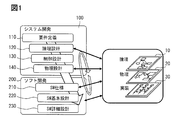
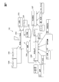
- FIG. 1 is an explanatory diagram showing a development procedure for system development.
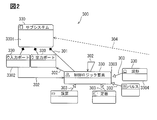
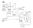
- FIG. 2 is an explanatory diagram showing a metamodel.
- FIG. 3 is an explanatory diagram showing a metamodel of requirement definition for system development.
- FIG. 4 is an explanatory diagram showing the design result of the requirement definition of the system development.
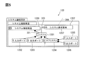
- FIG. 5 is an explanatory diagram showing a metamodel of the logical design of system development.
- FIG. 6 is an explanatory diagram showing the design result of the logical design of the system development.
- FIG. 7 is an explanatory diagram showing a metamodel of control design for system development.
- FIG. 1 is an explanatory diagram showing a development procedure for system development.
- FIG. 2 is an explanatory diagram showing a metamodel.
- FIG. 3 is an explanatory diagram showing a metamodel of requirement definition for system development.
- FIG. 4 is an explanatory diagram showing the design result of the requirement definition of the system development.
- FIG. 5 is an explanatory diagram showing a meta
- FIG. 8 is an explanatory diagram showing the design result of the control design of the system development.
- FIG. 9 is an explanatory diagram showing a metamodel of the physical design of system development.
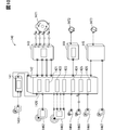
- FIG. 10 is an explanatory diagram showing the design result of the physical design of the system development.
- FIG. 11 is an explanatory diagram showing a metamodel of the specification definition of software development.
- FIG. 12 is an explanatory diagram showing the design result of the specification definition of software development.
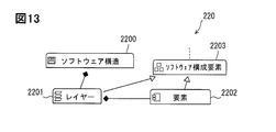
- FIG. 13 is an explanatory diagram showing a metamodel of the basic design of software development.
- FIG. 14 is an explanatory diagram showing the design result of the basic design of software development.
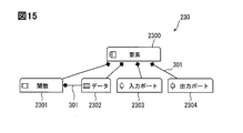
- FIG. 15 is an explanatory diagram showing a metamodel of detailed design of software development.
- FIG. 16 is an explanatory diagram showing the design result of the detailed design of software development.
- FIG. 17 is an explanatory diagram showing the design result of the detailed design of software development.
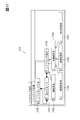
- FIG. 18 is an explanatory diagram showing the relationship between the database and the view.
- FIG. 19 is an explanatory diagram showing the relationship between the database and the view.
- FIG. 20 is an explanatory view showing an example of a view.
- FIG. 21 is an explanatory diagram showing the data structure of the database.
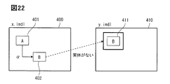
- FIG. 22 is an explanatory diagram showing inconsistencies between the design results.
- FIG. 23 is an explanatory diagram showing inconsistencies between the design results.
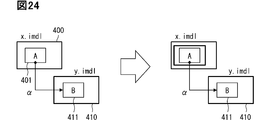
- FIG. 24 is an explanatory diagram showing inconsistencies between the design results.
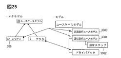
- FIG. 25 is an explanatory diagram showing the inconsistency between the metamodel and the design result.
- FIG. 26 is an explanatory diagram showing a derivation relationship.
- FIG. 27 is an explanatory diagram showing a derivation relationship.
- requirement definition 110 is first performed.
- Requirement definition 110 is the setting of development goals, for example, to define cruise control.
- the logical design 120 is entered.
- the logical design 120 is to define a function definition and an input and an output.
- inputs include a driver's request, a driving condition of a car, and a road condition including the presence or absence of traffic congestion.
- output there are control items for what kind of control is performed, such as the degree of accelerator, the degree of braking, and the steering wheel operation.
- the control design 130 is a circuit design, and determines what kind of calculation formula is used for each control. For example, how to detect vehicle speed and obstacles.
- the physical design 140 is literally a design of which ECU the control is physically assigned to. For example, there is a division of roles between calculating the vehicle speed detection by the sensor ECU and calculating it by the engine control ECU.
- the software development 200 is a development in which the outline defined in the above system development 100 is concretely incorporated into the software, and the software specification definition 210 is first defined.
- the software specification definition 210 defines more specific details of the engine control ECU.
- each function defined in the system development 100 is divided into a plurality of layers, and what kind of input is obtained and how is output for each function is determined. Then, if there is a problem between the input and the output, how to check is determined.
- the detailed software design 230 is performed.
- the detailed design summarizes specific calculation methods in a flowchart or the like so that they can be described in a program language.
- the source code of the program is determined by this detailed design 230.
- the design system of this embodiment can be applied to both top-down development and bottom-up development due to the flexibility described later. However, whether it is top-down development or bottom-up development, detailed design of software that defines detailed controls from requirement definition 110 that determines what kind of system to create and creates specific flowcharts, etc. By 230 there are numerous definitions, which must always be inherited consistently.
- the design support tool of this embodiment can handle all a series of development designs from the requirement definition 110 of the system development 100 to the detailed design 230 of the software development 200.
- the design support tool of this embodiment does not necessarily have to be used in all processes. Depending on the content of development, for example, it may be used only for system development 100, or it may be used only for the process of requirement definition 110 of system development 100, or it may be used for the process of requirement definition 110 of system development 100 and specification definition of software development 200. It is also possible to use it in the process of only 210.
- the configuration adopted by the design support tool of this embodiment describes the development from the requirement definition 110 of the system development 100 to the detailed design 230 of the software development 200 described above, first, the items to be designed are represented as the metamodel 300, and the metamodel. Design based on 300.
- each design process 110, 120, 130, 140, 210, 220, and 230 includes the formulation of a metamodel 300 that determines the direction of development, and the design result 305 that is made based on the metamodel 300.
- the metamodel 300 defines the relationship between the two by connecting the relationships between the metaclasses 330, which are the elements constituting the metamodel, with a line.
- the line showing a black square at the tip connecting the first metaclass 3301 and the second metaclass 3302 represents the possession 301 defined in the vertical relationship, and the lower second metaclass 3302 is the upper first. Indicates that it is an element of metaclass 3301.
- the arrow connecting the second metaclass 3302 and the third metaclass 3303 represents the reference 302, and the content specified by the second metaclass 3302, for example, the field operates with reference to the field specified by the third metaclass. Indicates that it is something to do.
- Reference 302 indicates that there is some relevance to the data exchanged between the two metaclasses.
- the input port of the second metaclass 3302 is in a relationship of referring to the data of the control logic element of the third metaclass 3303.
- the relationship between the second metaclass 3302 and the third metaclass 3303 does not have to be in a hierarchical relationship, nor does it need to be in the same process. It is also possible for the input port of the second metaclass 3302 to refer to the contents of the control logic element designed in another process.
- the line showing a white triangle at the tip connecting the third metaclass 3303 and the fourth metaclass 3304 represents the inheritance 303, and the fourth metaclass 3304 is at the same level as the third metaclass 3303, in other words.
- the fourth metaclass 3304 indicates that it is one type of the third metaclass 3303.
- the third metaclass 3303 is a control logic element and the fourth metaclass 3304 is a waveform
- a waveform can be mentioned as one type of control logic element.
- the broken line represents the derivation 304
- the derivation 304 shows the relationship with other processes.
- the metaclass 330 of one process and the metaclass 330 of another process are connected by the derivation 304 relationship, it is based on the content of the metaclass 330 of one process. It shows that the metaclass 330 of the other process is defined.
- This derivation 304 is used as trace information, and details will be described later. However, by specifying the relationship of the derivation 304 between the request source and the request destination, it is possible to trace the design information across the processes.
- the design result 305 embodies the contents of the metaclass 330.
- the design result 305 uses three input ports, a first input port, a second input port, and a third input port, and is more specific than the name and size of the input port. Prescribe the content. Therefore, the design result 305 based on one metaclass may have a plurality of components. The relationship between each component includes ownership 301 and reference 302.
- FIG. 3 shows an example of the metamodel 300 of the requirement definition 110.
- the system requirement 111 is listed as the meta class 330, and further, the system requirement 111 defines the first system requirement 1110 and the second system requirement 1111 which has a relationship between the first system requirement 1110 and the possession 301. That is, the metamodel 300 stipulates that the system requirement 111 is multiplex.
- the second system requirement 1111 has a relationship of inheritance 303 between the metaclass 330 of the functional requirement 112 and the metaclass 330 of the non-functional requirement 113.
- the metaclass 330 of the non-functional requirement 113 has the relationship of the reliability requirement 114, the maintainability requirement 115, and the metaclass 330 of the efficiency requirement 116 as inheritance 303. Therefore, it is defined that the second system requirement 1111 has a functional requirement 112 and a non-functional requirement 113 of the reliability requirement 114, the maintainability requirement 115, and the efficiency requirement 116.
- the design of the requirement definition 110 is performed according to this metamodel 300.
- the constant speed running 117 is included, and in order to perform the constant speed running 117, the setting 1171 by the driver and the actual constant speed running are performed. Traveling 1172, which is the various requirements of the above, is required.
- For setting by the driver check the signal input from various devices such as the setting switch.
- the constant speed running 118 that calculates the acceleration / deceleration required to maintain the target speed and outputs the request to the engine control ECU, and the speed adjustment in various modes according to the driver's request are performed. It is necessary to adjust the target speed to be performed 119. Even when the constant speed running 118 is performed, the presence or absence of the preceding vehicle, the speed of the preceding vehicle, etc. are detected in the follow-up mode to calculate the maintenance speed of the vehicle speed 1181, or the engine control ECU controls the vehicle speed to make it more suitable. Make request 1182.
- Constant speed running 117, setting 1171, running 1172, implementation of constant speed running 118, target speed setting 119, items 1181, 1182, and study item 1191 all correspond to the multiplexed system requirement 111, and the system.
- Constant speed running 117, setting 1171, running 1172, implementation of constant speed running 118, target speed setting 119, items 1181, 1182, and study item 1191 all correspond to the multiplexed system requirement 111, and the system.
- each item of constant speed running 117, setting 1171, running 1172, execution of constant speed running 118, target speed setting 119, item 1181, 1182, and examination item 1191 becomes each component in the design result 305.
- the relationship between each component is the relationship of reference 302.
- FIG. 5 shows an example of the metamodel 300 of the logical design 120.
- the metaclass 330 of the system 1201 has a relationship of possession 301 with the system functional structure 1200, and the system functional structure 1200 defines that the system 1201 is included. Further, the system 1201 has a relationship of possession 301 with the metaclass 330 of the input port 1202, the output port 1203 and the subsystem 1204, and the system 1201 has the input port 1202, the output port 203 and the subsystem 1204. Similarly, subsystem 1204 also has input port 1205 and output port 1206.
- the system 1201 has a relationship between the metaclass 330 of the system component 1207 and the inheritance 303, and it is stipulated that the system 1201 includes the system component 1207. Further, the metaclass 330 of the system component 1207 defines the relationship of the derivation 304, and the relationship of the derivation 304 is defined in the system requirement 111 of the metamodel 300 of the requirement definition 110, more specifically, the metaclass 330 of the second system requirement 1111. It is tied. Therefore, it is defined that the system 1201 of the logical design 120 is derived from the system requirement 111 of the requirement definition 110 via the system component 1207.
- a deceleration determination 1211 for determining whether or not an operation for requesting deceleration has been performed by the driver, or an operation for requesting acceleration has been performed.
- the vehicle speed setting determination 1213 is performed.
- the inter-vehicle distance determination 1214 for determining whether or not the driver has performed an operation to shorten the inter-vehicle distance with the preceding vehicle and the inter-vehicle length determination 1215 for determining whether or not the operation for increasing the inter-vehicle distance has been performed are performed.
- the inter-vehicle distance setting determination 1216 for determining the inter-vehicle distance is performed.
- the vehicle speed calculation item 122 the vehicle speed is calculated by the acceleration calculation 1221 that calculates the acceleration / deceleration based on the signals from various sensors and the wheel calculation 1222 that determines the actual wheel speed. Then, the difference between the vehicle speed calculated by the vehicle speed calculation item 122 and the required vehicle speed determined by the vehicle speed setting determination 1213 of the driver's request determination item 121 is calculated by the vehicle speed difference calculation item 123. Similarly, in the inter-vehicle distance difference calculation item 124, the difference between the inter-vehicle distance setting determination 1216 defined in the request determination item 121 and the inter-vehicle distance defined in the inter-vehicle distance calculation item 125 is calculated by the inter-vehicle distance difference calculation 1241.
- the information is input to the driver notification output item 127 and the target acceleration / deceleration amount calculation item 128.
- the driver notification output item 127 determines how quickly and appropriately the information such as the vehicle speed is displayed to the driver by the display output 1271, and determines the information to be output to various devices such as a meter.
- the system functional structure 1200 shows the overall structure, and the system 1201 included therein shows the driver's request determination item 121, the vehicle speed calculation item 122, the vehicle speed difference calculation item 123, and the inter-vehicle distance difference calculation.
- Item 124, inter-vehicle distance calculation item 125, system state determination item 126, driver notification output item 127, and target acceleration / deceleration amount calculation item 128 correspond to each other.
- Each system 1201 is provided with an input port 1202 and an output port 1203.
- each subsystem 1204 includes an input port 1205 and an output port 1206.
- the subsystem 1204 corresponds to the metaclass 330, and the deceleration judgment 1211, the speed increase judgment 1212, the vehicle speed setting judgment 1213, the vehicle distance short judgment 1214, and the vehicle distance length judgment 1215 and the inter-vehicle distance setting determination 1216 are each component of the design result 305.
- control design 130 designs the control in the system 1201 and the subsystem 1204 of the logical design 120, and the input port 1300 and the output port 1301 are the inputs of the input port 1202, the output port 1203, and the subsystem 1204 of the system 1201. Corresponds to port 1205 and output port 1206.
- control logic element 1302 has a relationship of reference 302 with the input port 1300 and the output port 1301, and the input port and the output port of the logical design 120 refer to the control logic element 1302.
- the waveform 1303, the pulse 1304, the constant 1305 and the calculation 1306 are in the relationship of inheritance 303, and the control logic is assembled using the waveform 1303, the pulse 1304, the constant 1305 and the calculation 1306. Is stipulated.
- the metaclass 330 of the operation 1306 has a relationship of the unary operation 1307 and the metaclass 330 of the polynomial operation 1308 and the inheritance 303, and the metaclass 330 of the unary operation 1307 and the polynomial operation 1308 also have a plurality of metaclasses 330 inherited 303. It is in. It is stipulated that the operation 1306 is performed using the items included in these metaclasses 330.
- FIG. 8 shows an example of the control design 130.
- This example corresponds to the system state determination item 126 of the logical design 120.
- the first and circuit 1311 calculates the signals of 12021 whether or not the ignition switch corresponding to the input port 1202 is turned on and the cruise control on / off state 12022. Then, the signal from the first and circuit 1311 and the delay signal of the unit are logically calculated by the X or circuit 1312, and the on / off of the cruise control is output.
- This output 12031 corresponds to the output port 1203 of the logical design 120.
- the output from the X or circuit 1312 and the cruise control mode signal 12023 are calculated by the second and circuit 1313.
- the mode signal 12023 corresponds to the input port 1202 of the logical design 120.
- the output of the second AND circuit 1313 and the delay signal of the unit are added and calculated by the addition circuit 1314, and the cruise control mode is output.
- the output 12032 corresponds to the output port 1203 of the logical design 120.
- the items defined in the logical design 120 are incorporated into a concrete logical operation formula.
- the input port corresponds to the metaclass 330.
- the components of the design result 305 include whether or not the ignition switch is turned on 12021 and the cruise control on / off state 12022.
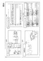
- FIG. 9 shows an example of the metamodel 300 of the physical design 140. At the top is the metaclass 330 of the system physical structure 1400, and the metaclass 330 of the element 1401 has a relationship of possession 301.
- An example of the element 1401 is the ECU 1402, as the metaclass 330 of the ECU 1402 has an inheritance 303 relationship.
- the element 1401 (ECU 1402) has a functional component assignment 1403, an input port 1404, and an output port so that the metaclass 330 of the element 1401 has a functional component assignment 1403, and the metaclass 330 of the input port 1404 and the output port 1405 has a possession 301. It is equipped with 1405.
- Derivation 304 is shown in the functional component allocation 1403, and the functional component allocation 1403 of the physical design 140 is in a relationship of the subsystem 1204 of the logical design 120 and the derivation 304. Therefore, subsystem 1204 will achieve the functionality specified in functional component assignment 1403. Further, the functional component allocation 1403 also includes a derivation 304 from the software specification definition 210, which will be described later.
- FIG. 10 shows an example of the design result 305 of the physical design.
- examples of the ECU 1402 that divides the roles include a brake ECU 141, an ADASEC 142 that supports automatic operation, a meter ECU 143, an engine control ECU 144, and a power steering ECU 145.
- each ECU 141, 142, 142, 144, 145 correspond to the input port 1404.
- the wheel speed sensor 1461 that outputs a pulse signal indicating the wheel speed
- the millimeter wave radar 1462 that calculates the inter-vehicle distance from the preceding vehicle by the internal ECU and outputs the inter-vehicle distance signal that is the calculation result
- the touch panel 1464 This is the driver's request setting, etc., which is judged by the operation of various buttons. Examples of driver operations include cruise control mode, vehicle speed setting, cruise control on / off, and inter-vehicle distance setting.
- the on / off signal from the ignition switch 1464 determines whether the engine is running or stopped.
- the lane is detected by the image information from the camera 1465. Further, the acceleration / deceleration acceleration in the yaw rate and the traveling direction is detected by the signal from the acceleration sensor 1466.
- the steering angle of the steering wheel is detected by the signal from the steering sensor 1467.
- the ADASEC 142 that supports automatic operation includes the following.
- Targets for which the calculation results of each ECU 1402 are output include a display related to the set inter-vehicle distance from the meter ECU 143, a cruise control on / off display, a set vehicle speed display, and a cruise control mode display. These displays are output to the in-vehicle display 1471.
- the engine control ECU 144 outputs a rotation signal of the throttle motor 1472 to the throttle valve that controls the intake air amount, more specifically, to the throttle motor 1472 that rotates the throttle valve.
- the power steering ECU 145 outputs a rotation signal of the power steering motor 1473 to the power steering device. These outputs correspond to the output port 1405 of the metamodel 300.
- the relationship between the metamodel 300 and the design result 305 is as described above.
- the metaclass 330 is the ECU 1402
- the brake ECU 141 the ADASEC 142 that supports automatic operation
- the meter ECU 143 the engine control ECU 144
- the power steering ECU 145 Corresponds to the design result 305 components.
- FIG. 11 shows an example of the metamodel 300 of the software specification definition 210.
- the relationship of possession 301 is between each metaclass 330 of software requirement specification 2100, requirement group 2101, and software requirement 2102. Therefore, the software requirement specification 2100 includes the requirement group 2101, and the requirement group 2101 has a multiple structure including the software requirement 2102.
- the metaclass 330 of the software requirement 2102 has a relationship of inheritance 303 between the metaclass 330 of the functional requirement 2103 and the non-functional requirement 2104, and the metaclass 330 of the non-functional requirement 2014 further includes the reliability requirement 2105, the efficiency requirement 2106, and the non-functional requirement 2104.
- the metaclass 330 of the maintainability requirement 2107 is in the relationship of inheritance 303. Therefore, the software requirement 2102 defines a function requirement 2103, a reliability requirement 2105, an efficiency requirement 2106, and a non-functional requirement 2104 of the maintainability requirement 2107.
- the metaclass 330 of the software request 2102 has a relationship with the metaclass 330 of the functional component allocation 1403 of the physical design 140 in the system development 100 described above and the derivation 304. Therefore, the function specified in the functional component allocation 1403 corresponds to the function request 2103 and the non-functional request 2104 in the software request 2102.
- FIG. 12 shows an example of the design result 305 of the software specification definition 210 in the software development 200.
- the software specification definition 210 defines what kind of software each ECU 1402 is in charge of. For example, in item 211 for the ADASEC 142 that supports automatic operation, the maintainability request 2120 for maintainability common to the ECU, the usability request 2121 for the usability common to the ECU, the efficiency request 2122 for the efficiency of the ECU, and the ECU. There is a reliability requirement 2123 for the reliability of.
- a lower layer is defined for each request 2120 to 2123.
- a software maintainability requirement 2130 that reduces the number of changes in the software when the software is used in other vehicles.
- a status display request 2131 of a function that always displays what is effective among the functions that support the user (driver) in automatic driving.
- Program size request 2132 is, for example, a request to keep the actual used area within 70% of the capacity of various memories.
- the CPU load request 2133 is, for example, a request for suppressing the average load of the CPU within 60% in a state of steady automatic driving support.
- steady automatic driving support for example, while driving along the lane (lane keeping assist), while preparing to always operate the emergency brake, while maintaining the distance from the preceding vehicle, An example of following running at a constant speed can be mentioned.
- the part reliability requirement 2134 that continues to operate in other parts that are not affected by the defect is set.
- Each of these requirements 2120-2123 and 2130-2134 corresponds to the non-functional requirements 2104 of the metamodel 300. Therefore, in the relationship between the metamodel 300 and the design result 305, the non-functional requirements 2104 are metaclass 330, and each request 2120-2123 or 2130-2134 corresponds to the component of the design result 305.
- FIG. 13 shows an example of the metamodel 300 of the software basic design 220.
- the software basic design 220 defines functions and data for realizing the requirements defined in the software specification definition 210. Since the software structure 2200, the layer 2201 and the metaclass 330 of the element 2202 are in the ownership relationship, the software structure 2200 includes the layer 2201, and the layer 2201 includes the element 2202.
- the metaclass 330 of the layer 2201 and the element 2202 has a relationship of the metaclass 330 of the software component 2203 and the inheritance 303, the layer 2201 and the element 2202 can be mentioned as the type of the software component 2203.
- the metaclass 330 of the software component 2203 has a relationship with the metaclass 330 of the software request 2102 of the software specification definition 210 and the derivation 304. Therefore, the layer 2201 of the software basic design 220 and the element 2202 included in the layer 2201 are related to the software requirement 2102 of the software specification definition 210.
- FIG. 14 shows an example of the design result 305 of this software basic design 220.
- the application layer (APP layer) 221 has items of a vehicle speed deviation 2210, an inter-vehicle distance deviation 2211, and a target control amount 2212.
- the application framework layer (AFW layer) 222 which is the layer below it, contains items such as the presence / absence of a preceding vehicle 2222, the cruise control control state 2221, and the external system control amount 2222.
- the platform layer (PF layer) 223 has items of preceding vehicle information 2230, own vehicle driving information 2231, external system state 2232, switch state 2233, and external system request 2234.
- the lowest layer, the hardware layer (HW layer) 224 is a network controller (reception) 2240 and an ignition that can also be used for in-vehicle devices as devices that output signals that are the prerequisites for each of the above items.
- the APP layer 221 and the AFW layer 222, the PF layer 223, and the HW layer 224 correspond to the layer 2201 of the metamodel 300. Then, the items of the vehicle speed deviation 2210, the inter-vehicle distance deviation 2211, and the target control amount 2212, the presence / absence of the preceding vehicle 2220, the control state of the cruise control 2221, the item of the external system control amount 2222, the preceding vehicle information 2230, and the own vehicle traveling information 2231.
- External system state 2232, switch state 2233, and items of external system request 2234 network controller (receive) 2240 that can also be used for in-vehicle devices, ignition switch 2241, various switches 2242, and networks that can also be used for in-vehicle devices.
- 2243 of the controller (transmission) 2243 corresponds to the element 2202 included in each layer 2201.
- each layer from the APP layer 221 to the HW layer 224 is shown by a broken line arrow.
- the signal from the ignition switch 2241 of the HW layer 224 is taken into the item of the external system state 2232 of the PF layer 223, and is taken into the item of the cruise control control state 2221 of the AFW layer 222 together with the item of the switch state 2233. Then, this control state 2221 is output to the vehicle speed deviation 2210 and the inter-vehicle distance deviation 2211 of the APP layer 221.
- the arrow in FIG. 14 shows the relationship between each layer 2201 of the design result 305, and has nothing to do with the arrow of the metamodel 300.
- layer 2201 is a metaclass 330
- APP layer 221 and AFW layer 222, PF layer 223, and HW layer 224 are components of the design result 305.
- the detailed software design 230 defines the detailed control for realizing the functions of the basic design 220.
- An example of the metamodel 300 is shown in FIG.
- the metaclass 330 of element 2300 is the same as the metaclass 330 of element 2202 of basic design 220.
- the metaclass 330 of the element 2300 has a relationship of possession 301 with each metaclass 330 of the function 2301, the data 2302, the input port 2303, and the output port 2304. Therefore, element 2300 includes function 2301, data 2302, input port 2303 and output port 2304.
- the metaclass 330 of the data 2302 is also owned by the metaclass 330 of the function 2301, the data 2302 is used for the element 2300 and also for the function 2301.
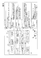
- the design result 305 of the software detailed design 230 defines the arithmetic processing by using, for example, a flowchart or a table as shown in FIG.
- the input items 231 are "1. Cruise control state”, “2. Vehicle speed”, “3. Presence / absence of preceding vehicle”, “4. Measured inter-vehicle distance", and “5. Set inter-vehicle distance”.
- the output item 232 includes "1. Difference between the measured inter-vehicle distance and the set inter-vehicle distance”.
- the internal data 233 includes "1. target vehicle speed” and "2. actually measured vehicle speed”.
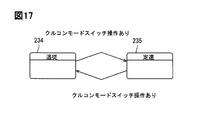
- the design result 305 of the software detailed design 230 shows that, for example, as shown in FIG. 17, the state when the cruise control switch is operated using the state transition control is the follow-up running 234 and the constant speed running 235. Indicates that it will switch with. Although the definitions of the follow-up running 234 and the constant speed running 235 are not described in the state transition of FIG. 17, the definitions are defined in detail in the actual detailed design.
- the input item 231 is a metaclass 330, and "1. Cruise control status", "2. Vehicle speed”, “3. Presence or absence of a preceding vehicle”, “4. Measured inter-vehicle distance”, “5. Set inter-vehicle distance”. "Distance” is a component of the design result 305.
- the design support tool of this embodiment defines all the series of development designs from the requirement definition 110 of the system development 100 to the detailed design 230 of the software development 200 in the metamodel 300, and defines the metamodel 300. Proceed with the design according to the contents. Then, the information of the metamodel 300 and the design result 305 during that period are recorded in one database 310 (FIG. 18).
- the database 310 does not have to be physically one, and may be distributed.
- the system state determination 3101 when the system state determination 3101 is written to the subsystem 3100 as a design result in the database 310, the system state determination 3101 can also be displayed as the system state determination 126 of the logical design 120 as shown in FIG. It can also be displayed as the system state determination 1425 of the design 140.
- the design support tool of this embodiment can display the design result 305 in a plurality of formats.
- the design tool of this embodiment can input design information from a plurality of screens.
- FIG. 19 shows the design result 305 of the software basic design 220
- the left view 307 is an ER diagram which is an entity-relationship diagram, which is the same as that of FIG.
- the description content of this ER diagram can also be displayed in the tabular view 307 on the right screen.
- the view 307 is displayed on the liquid crystal display 320 (FIG. 27).
- the tabular view 307 describes as the debt of the APP layer 221 "the target amount of acceleration / deceleration is displayed from the difference between the vehicle speed and the inter-vehicle distance", and the element 2202 is "1. inter-vehicle distance deviation 2211". , "2. Target control amount 2212", “3. Vehicle speed deviation 2210", and the responsibilities of each element 2202 are described. The same applies to the layer 2201 below the AFW layer 222.
- the format of the view 307 used in the design tool of this embodiment is not limited to the ER diagram 3070 and the tabular document form 3072, but can also be represented as a tree diagram 3071 or a tree grid 3073 as shown in FIG. The designer can appropriately select an easy-to-use view 307 according to each design need.
- An ER diagram 3070 is preferred for an overview of the overall structure, and document form 3072 is preferred for defining the details of each item.
- the four types of views 307 of FIG. 20 are examples that are easy to use for designing, the views 307 used in the design support tool of this embodiment are not limited to these four types. .. On the contrary, it is possible to reduce the number of types of views 307 to less than four.
- the design support tool of this embodiment simply changes the appearance of each component based on the data stored in the database 310 for the display of each view 307. Therefore, any view is used.
- the input from 307 is the same as the input to the database 310.
- FIG. 21 shows an example of how to hold data in the database 310.
- the connection 148 is specified by the ID 1480 of the connection 148 itself, the ID 1488 of the association source, and the ID 1482 of the association destination in the database 310. Do. Then, various data related to the connection 148 are stored. For example, there are names, data itself, data versions, deletion information, and the like.
- connection 148 in FIG. 21 is the relationship of the reference 302.
- the relationship between the metaclass 330 includes the possession 301, the reference 302, the inheritance 303, and the derivation 304, the relationship is stored in the database 310. ..
- the information stored in the database 310 there is also a relationship between the metaclass 330 and the components of the design result 305 based on the metaclass 330.
- the ID information of each component and the ID information of the metaclass 330 related to the component are stored.
- the metaclass 330 may correspond to a plurality of other components of the design result 305. At that time, not only the information between the metaclass 330 and the components but also the information between the components is stored in the database 310. Relationships between components include ownership and reference.
- the metamodel 300 can be defined by using the various views 307 shown in FIG. 20, and the metamodel 300 can be designed in correspondence with the metamodel 300. Then, only by designing with any one view 307, the design result 305 can be displayed in all the views 307 formats of FIG. 20.
- the related design result 305 is always the latest, and there is no concern about update omission in the design support tool of this embodiment.
- the design support tool of this embodiment can freely change the metamodel 300 and the design result 305 in each design process without being bound by a specific rule. Therefore, it is possible to carry out detailed design by examining each component side only by defining a rough design by top-down development. It is a design support tool suitable for large-scale system development.
- the design support tool of this embodiment is bottom-up because the metamodel 300 and the design result 305 can be rewritten in each design process even when performing a high-level design using the components designed in detail in the low-level design. Also suitable for design.
- component A401 and component B402 are used in X design result 400, and when the component B402 refers to component B411 of Y design result 410, the component in Y design result 410.
- component B411 is deleted, an inconsistency occurs between the X design result 400 and the Y design result 410.
- component A401 and the component B402 are used in the X design result 400 and the component B402 refers to the component B411 of the Y design result 410, the same component B has the Z design. If it is also defined as component B421 of result 420, an inconsistency will occur between component B411 of Y design result 410 and component B421 of Z design result 420.
- the component A401 of the X design result 400 may be deleted while the component B411 of the Y design result 410 refers to the component A401 of the X design result 400. Inconsistency occurs in which the design result 305 of the citation destination is deleted and the actual situation disappears.
- the use case 308 corresponds to the constant speed running 3080 and the following running 3081, but when the following step 3082 is further added to the following running 3081, between the metamodel 300 and the design result 305. Inconsistency occurs.
- the design support tool of this embodiment can make corrections at each point of design as described above, it is allowed that such inconsistency occurs. By allowing this inconsistency, it is possible to provide flexibility as a design support tool and continue the design without stressing the designer.
- the design support tool of this embodiment detects the inconsistency and notifies the designer of the inconsistency, and the designer designs in a consistent metamodel 300 and based on the metamodel 300.
- the result 305 can be easily corrected. Inconsistency is detected when the file is opened or when the metamodel 300 is changed by deleting, editing, or merging.
- the display "A deleted model was found.” Is displayed on the display 320 (FIG. 27), and the file name of the X design result 400 and the component that is the related source are displayed.
- the class name of A401, the related class name of related a403, and the index number of the collection indicating the metamodel of component B402 are displayed.
- the metaclass 330, the corresponding component A401, and the component B402 are stored in the database 310, and the component A401 and the component B402 are also stored in a reference relationship. is there. Therefore, it can be detected that the deletion of the component B402 causes an inconsistency in the reference relationship.
- the display "A duplicate model was found in a plurality of files" is displayed on the display 320, the file names of the Y design result 410 and the Z design result 420, and the component B411. , 421 model paths are displayed.
- the database 310 stores that the component B402 of the X design result 400 and the component B411 of the Y design result 410 are in a reference relationship together with their respective ID information.
- the fact that the component B 402 of the X design result 400 and the component B421 of the Z design result 420 are in a reference relationship is also stored together with the respective ID information. Therefore, the database 310 can detect inconsistencies in the reference relationships.
- the designer does not need to use a special inconsistency correction function. For example, it is possible to adopt the component B411 found first and skip the component B421 found later.
- the component B411 found first may be deleted and the component B421 found later may be adopted by using the normal editor function. Conversely, it is also possible to delete the component B421 found later.
- the design support tool of this embodiment shows on the display 320 that "a model without a parent has been found" when an inconsistency is detected, and the file name of the X design result 400 And the related class name of the related a403 is displayed.
- the design support tool of this embodiment has the same operation as when the Y design result 410 is read by itself, and does not provide a special inconsistency correction function.
- the designer responds by moving the X design result 400 to an appropriate position or canceling the deletion of the X design result 400 by using a normal design function.
- an error message is displayed even when the operation that caused the inconsistency is performed.
- the design support tool displays an error message even when the X design result 400 is deleted.
- the relationship between the components of the design result 305 was a reference relationship, but similar inconsistencies can also be detected in the ownership relationship.
- the database 310 stores references and ownership as information between the components of the design result 305.
- the display 320 shows the message "A model in which the metamodel does not exist" is displayed, and the model file name of the metamodel 300 Display the model name of follow-up step 3082 corresponding to non-existent use case 308.
- the database 310 stores the relationship between the metaclass 330 of use case 308 and the components of the design result 305.
- the follow-up step 3082 When the follow-up step 3082 is added as a component, the follow-up step 3082 has a relationship that is not in the metaclass 330, so that the inconsistency can be detected.
- the design support tool of this embodiment does not provide a special inconsistency correction function.
- the designer can correct the inconsistency by deleting the follow-up step 3082 using a normal editor function.
- the design support tool of this embodiment can display the above error message because the database 310 stores the relationship between the possession 301 and the reference 302 as information.
- the possession 301 and the reference 302 define the relationship between different metaclasses 330, and the components of the design result 305 in each process follow this relationship by being associated with the metaclass 330.
- the possession 301 and the reference 302 are also stored in the database 310 as information between the components of the design result 305. Therefore, if there is a contradiction between the component of the design result 305 and the metaclass 330, or in the interrelationship of the components, the database 310 can detect the contradiction.
- the design tool of this example automatically ensures traceability. Top-down development is easy to understand, but in the development from the requirement definition 110 of the system development 100 to the detailed design 230 of the software development 200, consistency is required between the upper process and the lower process. "Traceability” is to centrally manage the relationships between work products (components) between these processes so that when a design, manufacturing, or maintenance problem occurs, the cause of the problem can be quickly traced. Management ".
- the design information from the upper process to the lower process is defined by the inheritance 303 and the derivation 304 in the metamodel 300, so that the metamodel of the lower process is associated with the metamodel 300 defined in the upper process. 300 can be created.
- the metamodel 300 of the upper process can be created in association with the metamodel 300 defined in the lower process.
- FIG. 26 is a diagram illustrating the operation of the derivation 304 on the display 320.
- the display 320 can display the requirement definition 110 of the upper process and the software basic design 220 of the lower process side by side on the left and right sides of the screen. Then, when trying to design the inter-vehicle distance deviation component 2211 on the APP layer 221 of the software basic design 220 on the right screen, drag the constant speed running 117 on the left screen with the mouse and drop it at the location of the inter-vehicle distance deviation component 2211. .. By this intuitive operation, the inter-vehicle distance deviation component 2211 is derived from the constant speed running 117.
- the derivation 304 is recorded by the designer operating the metamodels 300 of the left and right screens on the screen and associating them with each other. That is, the database 310 automatically records the designer's derivation operation as trace information.
- the database 310 automatically records that the inter-vehicle distance deviation component 2211 and the constant speed running 117 have a derivation 304 relationship. More specifically, at what point in time the derivation 304 was performed is stored in the database 310. What is stored in the database 310 is the relationship of the derivation 304, the ID information of the derivation destination, and the ID information of the derivation source. Therefore, the relationship of the derivation 304 can be used as trace information.
- the designer can intuitively grasp the relationship of the derivation 304 by connecting the relationship with a line.
- the requirement definition 110, the logical design 120, and the physical design of the system development 100, and the software specification definition 210 and the basic design are displayed side by side on the display 320, and the relationship of the derivation 304 is connected by a line.
- the constant speed running 117 of the requirement definition 110, the driver notification output 127 of the logical design 120, the meter ECU 143 of the physical design 140, the following running 2109 of the software specification definition 210, and the vehicle speed deviation 2210 of the basic design 220 are derived.
- the design support tool of this embodiment the metamodel 300 in each process of design is defined, and the design in accordance with the regulation is defined. Then, the derivation 304 relationship between each component of the upper process and the lower process is stored in the database 310. Therefore, the design support tool of this embodiment can intuitively grasp whether all the requirements of the upper process are incorporated into the functions of the lower process. In other words, it is possible to grasp whether or not a function that is not required by the upper process is created in the lower process. Therefore, when making a design change, it is possible to grasp the range affected by the design change.
- the display 320 usually uses the liquid crystal screen of a computer, but it can also be printed out on a paper medium if necessary.
- the design support tool is usually operated by using a mouse or a keyboard, but input information can also be operated by image recognition or voice recognition. Further, the design support tool may be operated by taking in the information input by another device.
- the design mode of the system development 100 is defined as the requirement definition 110, the logical design 120, the control design 130, and the physical design 140, and the design mode of the software development 200 is defined as the specification definition 210, the basic design 220, and the detailed design 230. It is common to do this, but other prescribed methods may be used.
- the design support tool of this embodiment can view the design results in a plurality of views, and the characteristics of the design support tool of this embodiment are not changed by the name of each process.
- the relationship between the metaclass 330 of the metamodel 300 includes all the possession 301, the reference 302, the inheritance 303, and the derivation 304, but some relationships may be deleted depending on the usage pattern. Conversely, additional relationships may be added.
- This disclosure can be used as a design support tool, and can be used for designing, for example, when developing a large-scale system such as an automatic driving system for an automobile.
- the present disclosure can also be used as a design support method.
- the design support method used in the design support tool that supports the design of at least one process defines a metamodel by at least one metaclass, designs the process based on this metamodel, and stores the design contents in the database.
- the design content is displayed as a view on the display, and the view of the display is a plurality of displays having different description formats.
Abstract
少なくとも一工程の設計を支援する設計支援ツールは、少なくとも一つのメタクラスによってメタモデルを定義し、工程の設計をこのメタモデルに基づいて行い、設計内容をデータベースに格納し、設計内容は、ディスプレイにビューとして表示され、ディスプレイのビューは、記載形式の異なる複数の表示である。
Description
本出願は、2019年9月23日に出願された日本特許出願番号2019-172388号に基づくもので、ここにその記載内容が参照により組み入れられる。
本開示は、自動車の自動運転等の大規模なシステムの開発に使用可能な設計支援ツールに関する。
プログラムの開発手法として、特許文献1には、開発すべき対象と開発の手順を表にまとめ、モデリングツールを用いてメタモデルを定義し、メタモデルを構成するブロックを特定したりメタモデルの意味を定めたりする手法が示されている。
特許文献1に記載のメタモデル生成装置は、設計者がコンピューターのディスプレイを見ながら、キーボードやマウスを操作してメタモデルを構成するブロックを特定できるようにしている。
しかしながら、特許文献1に記載のメタモデル生成装置は、専らメタモデルの生成に関する技術である。そのため、設計者が実際にディスプレイを見ながら操作する際に、設計内容をどのような形態で設計者に表示するのかは、検討していない。
一般に、メタモデル等のプログラムを作成するソフトウェアは、そのソフトウェアに適した表示形式を採用している。例えば、プログラムの詳細を設計する場合には、表形式でプログラムを表示ことが多く、プログラムの全体構造を設計する場合には、ダイヤグラム形式でプログラムを表示することが多い。そのため、特許文献1に記載のメタモデル生成装置は、そのプログラムに適した単一の表示形式でプログラムを表示していると考えられる。
ただ、例えば、自動車の自動運転のシステム開発を行う場合には、非常に多くのソフトウェアが組み合わされて全体のプログラムが構成される。そのため、膨大なプログラムの全体像を把握するニーズもあり、一方で、ソフトウェアの詳細を確認するニーズもある。
本開示は上記点に鑑みてなされたもので、設計者がプログラムを設計する場合や、設計したプログラムを確認する場合に、設計者のニーズに応じた形態でプログラムを表示できるようにすることを課題とする。
本開示の第1の態様は、少なくとも一工程の設計を支援する設計支援ツールである。そして、少なくとも一つのメタクラスによってメタモデルを定義し、工程の設計をこのメタモデルに基づいて行い、設計内容をデータベースに格納する。第1の態様は、設計内容をディスプレイにビューとして表示し、このビューは、記載形式の異なる複数の表示である。第1の態様によれば、設計者は設計内容に応じてビューの表示を切り替えることができる。例えば、設計内容の全体像を把握するにはERダイヤグラムを用いることができ、詳細な設計を行う際にはドキュメントフォームを用いることができる。設計者は自身が望むビューを用いて設計ができるので、効率的に設計することが可能である。
本開示の第2の態様は、ディスプレイのビューは、ERダイヤグラム、ツリーダイアグラム、ドキュメントフォーム及びツリーグリッドの中の少なくとも二つの表示である。設計者は多様なビューの選択が可能である。
本開示の第3の態様は、少なくとも二つの表示が、同時にディスプレイのビューに表示される。第3の態様によれば、設計者は設計内容に応じて二つ以上のビューを見比べることができる。例えば、ERダイヤグラムを用いて設計内容の全体像を把握しつつ、ドキュメントフォームを用いて詳細な設計を行うことができる。そのため、設計者は効率的に設計することが可能である。
本開示の第4の態様は、少なくとも二工程の設計を支援する。そして、少なくとも二工程がディスプレイのビューに同時に表示される。第4の態様によれば、設計者は設計内容に応じて二つ以上のビューを見比べることができる。例えば、ERダイヤグラムを用いてシステム開発の要件定義を確認しつつ、ドキュメントフォームを用いてソフトウェア開発の詳細設計を行うことができる。そのため、設計者は効率的に設計することが可能である。
本開示の第5の態様は、いずれかのディスプレイのビューで、少なくともメタモデル若しくはメタモデルに基づく設計内容のいずれかで生成、変更、削除を行うと、ディスプレイの他のビューでその生成、変更、削除が反映される。
本開示の第6の態様は、いずれかの工程は、システム開発の要件定義、論理設計、制御設計、及び物理設計と、ソフトウェア開発の仕様定義、基本設計、及び詳細設計の中から選択される。第6の態様に関する工程は、大規模なシステムの開発に適している。
設計者は、自身で設計しやすいと判断するビューを用いて、メタモデルやそれに基づく設計内容の生成、変更、削除を行うだけで、その生成、変更、削除をデータベースに反映させることができる。そのため、設計者は効率的に設計することが可能である。
本開示についての上記目的およびその他の目的、特徴や利点は、添付の図面を参照しながら下記の詳細な記述により、より明確になる。その図面は、
図1は、システム開発の開発手順を示す説明図であり、
図2は、メタモデルを示す説明図であり、
図3は、システム開発の要件定義のメタモデルを示す説明図であり、
図4は、システム開発の要件定義の設計結果を示す説明図であり、
図5は、システム開発の論理設計のメタモデルを示す説明図であり、
図6は、システム開発の論理設計の設計結果を示す説明図であり、
図7は、システム開発の制御設計のメタモデルを示す説明図であり、
図8は、システム開発の制御設計の設計結果を示す説明図であり、
図9は、システム開発の物理設計のメタモデルを示す説明図であり、
図10は、システム開発の物理設計の設計結果を示す説明図であり、
図11は、ソフトウェア開発の仕様定義のメタモデルを示す説明図であり、
図12は、ソフトウェア開発の仕様定義の設計結果を示す説明図であり、
図13は、ソフトウェア開発の基本設計のメタモデルを示す説明図であり、
図14は、ソフトウェア開発の基本設計の設計結果を示す説明図であり、
図15は、ソフトウェア開発の詳細設計のメタモデルを示す説明図であり、
図16は、ソフトウェア開発の詳細設計の設計結果を示す説明図であり、
図17は、ソフトウェア開発の詳細設計の設計結果を示す説明図であり、
図18は、データベースとビューとの関係を示す説明図であり、
図19は、データベースとビューとの関係を示す説明図であり、
図20は、ビューの例を示す説明図であり、
図21は、データベースのデータ構造を示す説明図であり、
図22は、設計結果間の不整合を示す説明図であり、
図23は、設計結果間の不整合を示す説明図であり、
図24は、設計結果間の不整合を示す説明図であり、
図25は、メタモデルと設計結果間の不整合を示す説明図であり、
図26は、導出関係を示す説明図であり、
図27は、導出関係を示す説明図である。
(実施例)
まず、一般的なシステム開発の流れを自動車の自動運転システムの例を用いて説明する。大きな手順として、先にシステム開発100を行い、次いでそのシステムに適合したソフトウェア開発200を行う。
まず、一般的なシステム開発の流れを自動車の自動運転システムの例を用いて説明する。大きな手順として、先にシステム開発100を行い、次いでそのシステムに適合したソフトウェア開発200を行う。
システム開発100では、図1に示すように、最初に要件定義110を行う。要件定義110は開発目標の設定であり、例えばクルーズコントロールを行うと定めることである。次いで、論理設計120に入る。論理設計120は、機能定義及び入力と出力とを定めることである。クルーズコントロールのシステムでは、入力としてドライバーの要請や、自動車の走行状態、渋滞の有無を含めた道路の状態等がある。出力としては、どのような制御を行うかの制御項目があり、アクセルの程度、ブレーキのかけ具合、ハンドル操作等がある。
システム開発100は、次いで制御設計130を行う。制御設計130は回路設計で、各制御でどのような計算式を用いるのかを定める。例えば、車速の検出や障害物の検出をどのように行うのか等がある。
その上で、物理設計140を行う。物理設計140は文字通り物理的にどのECUに制御を割り振るのかの設計である。例えば、車速検出をセンサECUで計算するのか、エンジンコントロールECUで計算させるのかの役割分担がある。
ソフトウェア開発200は、以上のシステム開発100で定めた概要を具体的にソフトウェアに落とし込む開発であり、まずソフトウェアの仕様定義210を定める。上記の物理設計140で車速検出機能をエンジンコントロールECUが受け持つとした際に、このソフトウェア仕様定義210でエンジンコントロールECUのより具体的な詳細を定める。
次いで、ソフトウェアの基本設計220を行う。この基本設計220ではシステム開発100で定めた各機能を複数のレイヤーに分割して、各機能毎にどのような入力を得てどのように出力するのかを定める。そして、入力と出力との間に支障がある場合にはどのようにチェックするのかを定める。
その後に、ソフトウェアの詳細設計230を行う。詳細設計は具体的な演算方法をフローチャート等にまとめ、プログラム言語で記載できるようにするものである。この詳細設計230によってプログラムのソースコードが確定する。
システム開発100でも、ソフトウェア開発200でも、別の観点で設計内容を現せば、論理式10を定め、それをどのように物理的に配置するのかの配置設計20を行い、具体的にECU上に実装する実装工程30を繰り返すこととなる。
上述の説明は、最上位工程である要件定義110から下位工程へ段階的に詳細化していくトップダウン開発の設計手順を説明したが、この設計手順は工程が進むにつれて設計内容が細分化されるため、トップから一貫した設計が可能である。ただし、システム全体の完全な理解が必要とされるため、大規模で複雑なシステムでは難易度が極めて高くなる。換言すれば、ある程度詳細なレベルまで進まなければシステム開発を進めることができない。
上述の説明とは逆に、最初にシステムを構成する個々のパーツを細部まで設計し、それらのパーツを組み合わせてシステムを開発するボトムアップ開発の設計手法もある。これは、すでに開発済の既存パーツを使用したり、各パーツを並行して開発したりするのに向いている。
一方で、各パーツを組み合わせたときに上位工程との間で不整合が生じたり、また、各パーツ間でも不整合が発生したりする可能性がある。また、このボトムアップ開発は、最適なパーツの開発は出来ても、部分最適となって全体最適とはならない場合もある。
本実施例の設計システムは、後述する柔軟性により、トップダウン開発にも、ボトムアップ開発にも適用することができる。ただ、トップダウン開発を行うにしろ、ボトムアップ開発を行うにしろ、どのようなシステムを作るのかを決める要件定義110から詳細な制御を定義して具体的なフローチャート等を作成するソフトウェアの詳細設計230までに多数の定義が存在し、それらは常に矛盾なく引き継がれなければならない。
本実施例の設計支援ツールでは、システム開発100の要件定義110からソフトウェア開発200の詳細設計230までの一連の開発設計を全て受け持つことが可能である。但し、本実施例の設計支援ツールは、必ずしも全ての工程に用いなければならないものではない。開発の内容に応じては、例えば、システム開発100のみに使用することも、システム開発100の要件定義110のみの工程に使用することも、システム開発100の要件定義110とソフトウェア開発200の仕様定義210のみの工程に使用することも可能である。
本実施例の設計支援ツールが採用する構成は、上述のシステム開発100の要件定義110からソフトウェア開発200の詳細設計230までの開発を、まず、設計すべき項目をメタモデル300として表し、メタモデル300に基づいて設計を行う。
従って、各設計工程110、120、130、140、210、220、及び230には、それぞれ開発の方向性を定めるメタモデル300の策定と、メタモデル300に基づきなされる設計結果305とがある。
メタモデル300は、図2に示すように、メタモデルを構成する要素であるメタクラス330間の関係を線で結んで両者の関係を規定している。図2の例で、第1メタクラス3301と第2メタクラス3302とを結ぶ先端に黒四角を示す線は、上下関係で規定する所有301を表し、下位である第2メタクラス3302は上位である第1メタクラス3301の要素であることを示す。
図2の例で、第2メタクラス3302と第3メタクラス3303とを結ぶ矢印は参照302を表し、第2メタクラス3302で規定する内容、例えばフィールドは、第3メタクラスで規定するフィールドを参照して動作するものであることを示す。参照302は両メタクラス間でやり取りされるデータに何らかの関連があることを示す。
例えば、第2メタクラス3302が入力ポートである場合、第2メタクラス3302の入力ポートは、第3メタクラス3303の制御ロジック要素のデータを参照302する関係となる。そして、第2メタクラス3302と第3メタクラス3303との関係は、上下関係である必要はなく、また、同一工程である必要もない。他の工程で設計した制御ロジック要素の内容を第2メタクラス3302の入力ポートが参照302することも可能である。
図2の例で、第3メタクラス3303と第4メタクラス3304とを結ぶ先端に白三角を示す線は継承303を表し、第4メタクラス3304は第3メタクラス3303と同一レベルであること、換言すれば、第4メタクラス3304は第3メタクラス3303の一種類であることを示す。
例えば、第3メタクラス3303が制御ロジック要素で、第4メタクラス3304が波形である場合、制御ロジック要素の一種類として波形が挙げられることを示している。
図2の例で、破線は導出304を表し、導出304は他の工程との関係を示している。例えば、システム開発100及びソフトウェア開発200の各工程の中で、一の工程のメタクラス330と他の工程のメタクラス330が導出304関係で結ばれていると、一の工程のメタクラス330の内容に基づいて他の工程のメタクラス330が規定されることを示している。この導出304は、トレース情報として用いられるもので、詳細は後述するが、導出304の関係を要求元と要求先で特定することで、工程を跨ぐ設計情報のトレースが可能となる。
設計結果305は、メタクラス330の内容を具体的にしたものである。例えば、メタクラス330が入力ポートである場合、設計結果305は、第1入力ポート、第2入力ポート、及び第3入力ポートの三つの入力ポートを用いるなど、入力ポートの名称やサイズ等より具体的内容を規定する。そのため、一のメタクラスに基づく設計結果305が複数のコンポーネントを持つ場合もある。各コンポーネント間の関係としては、所有301と参照302がある。
以下に、本実施例の設計支援ツールの使用例を、自動運転システムの開発に使用する例を用いてより詳細に説明する。
図3は、要件定義110のメタモデル300の一例を示す。メタクラス330としてシステム要件111を挙げており、更に、システム要件111は、第1システム要件1110とこの第1システム要件1110と所有301の関係にある第2システム要件1111が規定される。即ち、メタモデル300ではシステム要件111が多重であることを規定している。
要件定義110のメタモデル300では、第2システム要件1111は、機能要件112のメタクラス330と非機能要件113のメタクラス330が継承303の関係にある。そして、非機能要件113のメタクラス330には、信頼性要件114、保守性要件115及び効率性要件116のメタクラス330が継承303の関係にある。従って、第2システム要件1111には、機能要件112と、信頼性要件114、保守性要件115及び効率性要件116の非機能要件113とがあることが規定される。
要件定義110の設計は、このメタモデル300に従って行われる。例えば図4に示すように、クルーズコントロールの場合には、定速走行117を行うことが含まれ、定速走行117を行うためには、ドライバーによる設定1171と実際に定速走行を行う上での各種要件である走行1172が必要になる。ドライバーによる設定には、設定スイッチ等各種機器からの信号入力を確認する。
走行1172を定めるためには、更に、目標速度維持に必要な加減速度を算出してエンジンコントロールECUに要求を出力する定速走行の実施118と、ドライバーの要求に応じた各種モードで速度調整を行う目標速度の調整119が必要となる。定速走行の実施118を行うに際しても、追従モードで先行車の有無や先行車の速度等を検出して車速の維持速度算出1181を行ったり、より適した車速とすべくエンジンコントロールECUに制御要求1182を行ったりする。
目標速度の調整119を行うためには、ドライバーからの目標速度の増加要求があったか、逆に目標速度の減少要求があったか等の要求を確認する。そして、目標速度を変更する場合にも急な加減速を控えてなだらかな増減とする。特に、追従モードでは目標速度と先行車の速度との比較等、各種の検討項目1191を検討することとなる。
このように、要件定義110の設計では、システムが達成したい機能の概要をシステム要件111として定め、その機能に関連する動作や、関連する制御対象等を書き出すこととなる。定速走行117、設定1171、走行1172、定速走行の実施118、目標速度設定119、項目1181、1182、及び検討項目1191は、いずれも多重化されたシステム要件111に対応し、かつ、システム要件111の機能要件112に対応する。
そして、定速走行117、設定1171、走行1172、定速走行の実施118、目標速度設定119、項目1181、1182、及び検討項目1191の各項目が、設計結果305での各コンポーネントとなる。各コンポーネント間の関係は参照302の関係となる。
図5は、論理設計120のメタモデル300の一例を示す。システム1201のメタクラス330はシステム機能構造1200と所有301の関係にあり、システム機能構造1200はシステム1201を含むことを規定している。また、システム1201は、入力ポート1202、出力ポート1203及びサブシステム1204のメタクラス330と所有301の関係にあり、システム1201は、入力ポート1202、出力ポート203及びサブシステム1204を有している。同様に、サブシステム1204も入力ポート1205と出力ポート1206を有している。
また、システム1201は、システム構成要素1207のメタクラス330と継承303の関係にあり、システム1201にはシステム構成要素1207が含まれることが規定されている。更に、システム構成要素1207のメタクラス330は導出304の関係が規定され、この導出304の関係は要件定義110のメタモデル300のシステム要件111、より具体的には第2システム要件1111のメタクラス330に結ばれている。従って、論理設計120のシステム1201は、システム構成要素1207を介して、要件定義110のシステム要件111から導出されるものであることが規定される。
論理設計120の設計は、図6に示すように、例えばドライバーの要求判定項目121では、ドライバーから減速を求める操作がなされたかどうかの判定を行う減速判定1211や、増速を求める操作がされたか否かの判定を行う増速判定1212に基づき、車速設定判断1213を行う。また、ドライバーが先行車との車間距離を縮める操作をしたかどうかの判定を行う車間短判定1214や、車間距離を長くとる操作をしたか否かの判定を行う車間長判定1215を行って、車間距離を定める車間設定判断1216を行う。
同様に、車速算出項目122では、各種センサからの信号に基づいて加減速度の演算を行う加速度演算1221、および、実際の車輪速度を定める車輪演算1222によって車速を算出する。そして、この車速算出項目122で演算された車速と、ドライバーの要求判定項目121の車速設定判断1213で判断された要求車速との差を、車速差分算出項目123で計算する。同様に、車間距離差分算出項目124では、要求判定項目121で定めた車間設定判定1216と車間距離算出項目125で定めた車間距離との差分を車間距離差分演算1241にて計算する。
この車間距離差分算出項目124からの設定車間距離と車間距離差分、車速差分算出項目123からの設定車速と車速差分、システム状態判定項目126からのクルーズコントロールのオンオフとクルーズコントロールのモード等の各種の情報が、ドライバー通知出力項目127と目標加減速量算出項目128に入力する。
ドライバー通知出力項目127はドライバーに車速等の情報をいかに素早くかつ適正に表示するかを表示出力1271で判断して、メータ等各種の機器に出力する情報を定める。目標加減速量算出項目128では、エンジンコントロールECUに出力する目標加減速度を演算する。
メタモデル300との関係では、例えば、システム機能構造1200が全体構造を示し、そこに含まれるシステム1201にはドライバーの要求判定項目121、車速算出項目122、車速差分算出項目123、車間距離差分算出項目124、車間距離算出項目125、システム状態判定項目126、ドライバー通知出力項目127及び目標加減速量算出項目128が対応する。各システム1201には入力ポート1202と出力ポート1203が設けられている。
システム1201としてドライバーの要求判定項目121を挙げると、そのサブシステム1204に対応するものは、減速判定1211、増速判定1212、車速設定判断1213、車間短判定1214、車間長判定1215、及び車間設定判断1216があり、各サブシステム1204は入力ポート1205と出力ポート1206を備えている。
これをメタクラス330と設計結果305のコンポーネントとの関係にすれば、メタクラス330にはサブシステム1204が対応し、減速判定1211、増速判定1212、車速設定判断1213、車間短判定1214、車間長判定1215、及び車間設定判断1216が設計結果305の各コンポーネントとなる。
次に、制御設計130のメタモデル300を図7に基づいて説明する。制御設計130は、論理設計120のシステム1201やサブシステム1204での制御を設計するもので、入力ポート1300及び出力ポート1301は、システム1201の入力ポート1202、出力ポート1203や、サブシステム1204の入力ポート1205、出力ポート1206に対応する。
図7に示すように、制御ロジック要素1302は入力ポート1300及び出力ポート1301と参照302の関係にあり、論理設計120の入力ポート及び出力ポートはこの制御ロジック要素1302を参照している。
そして、制御ロジック要素1302のメタクラス330には、波形1303、パルス1304、定数1305及び演算1306が継承303の関係にあり、波形1303、パルス1304、定数1305及び演算1306を用いて制御ロジックが組まれることが規定されている。
更に、演算1306のメタクラス330は、単項演算1307と多項演算1308のメタクラス330と継承303の関係にあり、かつ、単項演算1307と多項演算1308のメタクラス330にもそれぞれ複数のメタクラス330が継承303関係にある。これらのメタクラス330に含まれる項目を用いて演算1306を行うことが規定されている。
図8は、制御設計130の一例を示す。この例は、論理設計120のシステム状態判定項目126に対応する。入力ポート1202に対応するイグニッションスイッチが入っているか否か12021と、クルーズコントロールのオンオフの状態12022との信号を、第1アンド回路1311で演算する。そして、この第1アンド回路1311からの信号とユニットの遅れ信号とをXオア回路1312で論理演算して、クルーズコントロールのオンオフを出力する。この出力12031は、論理設計120の出力ポート1203に対応する。
また、Xオア回路1312からの出力とクルーズコントロールのモード信号12023を、第2アンド回路1313で演算する。ここで、モード信号12023は、論理設計120の入力ポート1202に対応する。そして、第2アンド回路1313の出力とユニットの遅れ信号を加算回路1314で加算演算して、クルーズコントロールのモードを出力する。出力12032が、論理設計120の出力ポート1203に対応する。
このように、制御設計130では論理設計120で定めた項目を具体的な論理演算式に落とし込む。メタモデル300と設計結果305との関係では、入力ポートがメタクラス330に対応する。そして、設計結果305のコンポーネントとしては、イグニッションスイッチが入っているか否か12021と、クルーズコントロールのオンオフの状態12022とが挙げられる。
図9は、物理設計140のメタモデル300の一例を示す。最上位にシステム物理構造1400のメタクラス330があり、要素1401のメタクラス330が所有301の関係にある。ECU1402のメタクラス330が継承303の関係にあるように、要素1401の一例はECU1402である。
要素1401のメタクラス330に機能コンポーネント割り当て1403、入力ポート1404及び出力ポート1405のメタクラス330が所有301の関係にあるように、要素1401(ECU1402)には、機能コンポーネント割り当て1403、入力ポート1404及び出力ポート1405が備わっている。
機能コンポーネント割り当て1403には導出304が示されており、物理設計140の機能コンポーネント割り当て1403は、論理設計120のサブシステム1204と導出304の関係にある。従って、サブシステム1204は、機能コンポーネント割り当て1403で規定される機能を達成することとなる。また、機能コンポーネント割り当て1403には、ソフトウェアの仕様定義210からの導出304もあるが、この点は後述する。
図10に物理設計の設計結果305の一例を示す。この例では、役割を分担するECU1402として、ブレーキECU141、自動運転を支援するADASECU142、メータECU143、エンジンコントロールECU144、及びパワステECU145が挙げられる。
各ECU141、142、142、144、145に入力するセンサ信号が入力ポート1404に対応する。本実施例では、以下の例がある。車輪速を示すパルス信号を出力する車輪速センサ1461、内部のECUで先行車との車間距離を算出してその算出結果である車間距離信号を出力するミリ波レーダ1462、タッチパネル1463に設けられた各種ボタンの操作で判断されるドライバーの要求設定等である。ドライバーの操作例としては、クルーズコントロールのモード、車速の設定、クルーズコントロールのオンオフや、車間距離の設定等がある。
イグニッションスイッチ1464からのオンオフ信号で、エンジンが運転中であるのか停止しているのかを判断する。カメラ1465からの画像情報で、車線を検出する。また、加速度センサ1466からの信号で、ヨーレートや進行方向の加減速の加速度を検出する。ステアリングセンサ1467からの信号により、ハンドルの操舵角度を検出する。
各ECU1402の処理内容としては、例えば、自動運転を支援するADASECU142には以下のものがある。車間距離算出1420、車速差分算出1421、車間距離差分算出1422、ドライバー入力判定1423、目標加減速量算出1424、システム状態判定1425、及び車両状態判定1426である。
各ECU1402での演算結果が出力される対象としては、メータECU143からの設定した車間距離に関する表示、クルーズコントロールのオンオフの表示、設定した車速の表示、及びクルーズコントロールのモードの表示がある。これらの表示が車載ディスプレイ1471に出力される。
また、エンジンコントロールECU144からは、吸入空気量を制御するスロットルバルブに対して、より具体的には、スロットルバルブを回動させるスロットルモータ1472に対して、スロットルモータ1472の回転信号が出力される。パワステECU145からは、パワーステアリング装置に対して、パワーステアリングモータ1473の回転信号が出力される。これらの出力が、メタモデル300の出力ポート1405に対応する。
メタモデル300と設計結果305との関係は、既述の通りであるが、例えば、メタクラス330をECU1402とした場合、ブレーキECU141、自動運転を支援するADASECU142、メータECU143、エンジンコントロールECU144、及びパワステECU145が設計結果305のコンポーネントに対応する。
続いて、ソフトウェア開発200の詳細を説明する。ソフトウェアの仕様定義210のメタモデル300の一例を図11に示す。所有301の関係は、ソフトウェア要求仕様2100、要求グループ2101、ソフトウェア要求2102の各メタクラス330の間にある。従って、ソフトウェア要求仕様2100は要求グループ2101を含み、要求グループ2101はソフトウェア要求2102を含む多重の構造となる。
ソフトウェア要求2102のメタクラス330には、機能要求2103と非機能要求2104のメタクラス330が継承303の関係にあり、非機能要求2014のメタクラス330は、更に、信頼性要求2105、効率性要求2106、及び保守性要求2107のメタクラス330が継承303の関係にある。従って、ソフトウェア要求2102には、機能要求2103と、信頼性要求2105、効率性要求2106、保守性要求2107の非機能要求2104とが規定される。
ソフトウェア要求2102のメタクラス330は、上述のシステム開発100における物理設計140の機能コンポーネント割り当て1403のメタクラス330と導出304の関係にある。従って、機能コンポーネント割り当て1403で規定される機能には、ソフトウェア要求2102での機能要求2103や非機能要求2104が対応する。
このソフトウェア開発200におけるソフトウェアの仕様定義210の設計結果305の一例を、図12に示す。ソフトウェア仕様定義210では、各ECU1402でどのようなソフトウェアを受け持つのかを定める。例えば、自動運転を支援するADASECU142に対する項目211では、ECUに共通する保守性に対する保守性要求2120、ECUに共通する使用性に対する使用性要求2121、ECUの効率性に対する効率性要求2122、及び、ECUの信頼性に対する信頼性要求2123がある。
各要求2120~2123に対しては更に下のレイヤーが定められる。例えば、保守性要求2120に対しては、ソフトウェアを他の車両にも用いるときにソフトウェアの変更箇所を少なくするソフトウェア保守性要求2130が挙げられる。また、使用性要求2121に対しては、ユーザー(ドライバー)に対して自動運転を支援する機能の内、何が有効となっているのかを常に表示する機能の状態表示要求2131が挙げられる。
効率性要求2122に対しては、プログラムサイズ要求2132とCPU負荷要求2133がある。プログラムサイズ要求2132は、例えば、各種メモリーの容量に対して実際の使用領域を70%以内に抑える要求である。また、CPU負荷要求2133は、例えば、定常的な自動運転支援の状態で、CPUの平均負荷を60%以内に抑える要求である。定常的な自動運転支援の例として、例えば、車線に沿った走行(レーン・キーピング・アシスト)を実行中で、緊急ブレーキを常に操作できるよう準備しつつ、先行車との車間距離を保ちながら、一定速度で追従走行をする例が挙げられる。
信頼性要求2123に対しては、例えば、ソフトウェアを構成するパーツの一部に不具合が生じた際にも、その不具合の影響を受けていない他のパーツでは動作を継続させるパーツ信頼性要求2134が挙げられる。これらの各要求2120~2123や2130~2134は、メタモデル300の非機能要求2104に対応する。従って、メタモデル300と設計結果305との関係では、非機能要求2104がメタクラス330であり、各要求2120~2123や2130~2134は、設計結果305のコンポーネントに対応する。
図13は、ソフトウェア基本設計220のメタモデル300の一例を示す。ソフトウェア基本設計220ではソフトウェア仕様定義210で定めた要求を実現するための、機能とデータとを定義する。ソフトウェア構造2200、レイヤー2201及び要素2202のメタクラス330が所有の関係にあるので、ソフトウェア構造2200にはレイヤー2201が含まれ、レイヤー2201には要素2202が含まれる。
また、レイヤー2201及び要素2202のメタクラス330がソフトウェア構成要素2203のメタクラス330と継承303の関係にあるので、ソフトウェア構成要素2203の種類としてレイヤー2201及び要素2202が挙げられることとなる。
そして、ソフトウェア構成要素2203のメタクラス330は、ソフトウェア仕様定義210のソフトウェア要求2102のメタクラス330と導出304の関係にある。従って、ソフトウェア基本設計220のレイヤー2201やレイヤー2201に含まれる要素2202は、ソフトウェア仕様定義210のソフトウェア要求2102と関係づけられている。
このソフトウェア基本設計220の設計結果305の一例を、図14に示す。例えば、自動運転ではアプリケーションレイヤー(APPレイヤー)221には、車速偏差2210、車間距離偏差2211、及び目標制御量2212の項目がある。その下のレイヤーであるアプリケーションフレームワークレイヤー(AFWレイヤー)222には、先行車の有無2220、クルーズコントロールの制御状態2221、外部システム制御量2222の項目が入る。
更にその下のレイヤーであるプラットフォームレイヤー(PFレイヤー)223には、先行車情報2230、自車走行情報2231、外部システム状態2232、スイッチ状態2233、及び外部システム要求2234の項目がある。そして、最も下のレイヤーであるハードウェアレイヤー(HWレイヤー)224には、上記各項目の前提となる信号を出力する各機器として、車載機器にも利用可能なネットワークのコントローラ(受信)2240、イグニッションスイッチ2241、各種スイッチ2242、及び車載機器にも利用可能なネットワークのコントローラ(送信)2243がある。
従って、APPレイヤー221、AFWレイヤー222、PFレイヤー223、HWレイヤー224が、メタモデル300のレイヤー2201に対応する。そして、車速偏差2210、車間距離偏差2211、及び目標制御量2212の項目、先行車の有無2220、クルーズコントロールの制御状態2221、外部システム制御量2222の項目、先行車情報2230、自車走行情報2231、外部システム状態2232、スイッチ状態2233、及び外部システム要求2234の項目、車載機器にも利用可能なネットワークのコントローラ(受信)2240、イグニッションスイッチ2241、各種スイッチ2242、及び車載機器にも利用可能なネットワークのコントローラ(送信)2243が、各レイヤー2201に含まれる要素2202に対応する。
なお、図14では、APPレイヤー221からHWレイヤー224までの各レイヤー間の関係を破線の矢印で示している。例えば、HWレイヤー224のイグニッションスイッチ2241からの信号はPFレイヤー223の外部システム状態2232の項目に取り込まれ、スイッチ状態2233の項目と共にAFWレイヤー222のクルーズコントロールの制御状態2221の項目に取り込まれる。そして、この制御状態2221は、APPレイヤー221の車速偏差2210と車間距離偏差2211に出力する。
従って、図14の矢印は、設計結果305の各レイヤー2201間の関係を示すもので、メタモデル300の矢印とは関係ない。
メタモデル300と設計結果305との関係も上述の通りである。例えば、レイヤー2201がメタクラス330であり、APPレイヤー221、AFWレイヤー222、PFレイヤー223、HWレイヤー224が、設計結果305のコンポーネントである。
ソフトウェアの詳細設計230は、この基本設計220の機能を実現するための詳細な制御を定義するものである。メタモデル300の一例を図15に示す。要素2300のメタクラス330は、基本設計220の要素2202のメタクラス330と同じである。
要素2300のメタクラス330には、関数2301、データ2302、入力ポート2303及び出力ポート2304の各メタクラス330と所有301の関係にある。従って、要素2300は、関数2301、データ2302、入力ポート2303及び出力ポート2304を備えている。
データ2302のメタクラス330は関数2301のメタクラス330にも所有301の関係となっているので、データ2302は、要素2300に用いられると共に、関数2301にも用いられることとなる。
このソフトウェア詳細設計230の設計結果305は、例えば、フローチャートを用いたり、また、図16のように、表を用いたりして演算処理を規定する。図16の例では、入力項目231として「1.クルーズコントロールの状態」、「2.車両の速度」、「3.先行車の有無」、「4.実測車間距離」、「5.設定車間距離」がある。出力項目232としては、「1.実測車間距離と設定車間距離との差」がある。内部データ233には、「1.目標車速」と「2.実測車速」がある。
このソフトウェア詳細設計230の設計結果305は、上記例以外に、例えば、図17のように状態遷移制御を用いてクルーズコントロールスイッチの操作がなされた際の状態が追従走行234と定速走行235とで切り替わることを示したりする。なお、図17の状態遷移では追従走行234と定速走行235の定義が記載されてないが、実際の詳細設計では定義を詳細に規定する。
メタモデル300と設計結果305との関係も上述の通りである。例えば、入力項目231がメタクラス330であり、「1.クルーズコントロールの状態」、「2.車両の速度」、「3.先行車の有無」、「4.実測車間距離」、「5.設定車間距離」が設計結果305のコンポーネントである。
このように、本実施例の設計支援ツールは、システム開発100の要件定義110からソフトウェア開発200の詳細設計230までの一連の開発設計を全てメタモデル300に定義して、このメタモデル300の定義内容に沿って設計を進める。そして、その間のメタモデル300の情報も設計結果305も一つのデータベース310(図18)で記録している。なお、データベース310は、物理的に一つである必要はなく、分散配置されてもよい。
例えば、データベース310に設計結果として、サブシステム3100にシステム状態判定3101が書き込まれると、そのシステム状態判定3101は、図18に示すように、論理設計120のシステム状態判定126としても表示でき、物理設計140のシステム状態判定1425としても表示できる。
本実施例の設計支援ツールは、図19に示すように、複数の形式で設計結果305を表示することができる。換言すれば、本実施例の設計ツールは、複数の画面から設計情報を入力することができる。図19はソフトウェア基本設計220の設計結果305を示しているが、左のビュー307は実体関連図であるERダイヤグラムで、図14と同じである。このERダイヤグラムの記載内容は、右側画面の表形式のビュー307でも表示できる。なお、ビュー307は、液晶ディスプレイ320(図27)に表示される。
表形式のビュー307は、APPレイヤー221の債務として、「加減速の目標量を車速と車間距離との差から表示する。」と記載し、要素2202には、「1.車間距離偏差2211」、「2.目標制御量2212」、「3.車速偏差2210」の名称と、それぞれの要素2202の責務が記載されている。AFWレイヤー222以下のレイヤー2201に付いても同様に表示される。
これは、ERダイヤグラムのビュー307でも、表形式のビュー307でも、単に表示の仕方が異なるのみで、データベース310内では同じ情報として格納されているからである。
本実施例の設計ツールで用いるビュー307の形式は、ERダイヤグラム3070、表形式のドキュメントフォーム3072に限らず、図20に示すように、ツリーダイアグラム3071やツリーグリッド3073として表すこともできる。設計者は設計の各ニーズに応じて使用しやすいビュー307を適宜選択することができる。全体の構造を概観するには、ERダイヤグラム3070が望ましく、各項目の詳細を定義するにはドキュメントフォーム3072が望ましい。
但し、図20の4種類のビュー307は、いずれも設計を行う上で利用しやすい例であるが、本実施例の設計支援ツールで用いるビュー307は、この4種類に限定されるものではない。逆に、ビュー307の種類を4種類より少なくすることも可能である。
本実施例の設計支援ツールは、既述のように、各ビュー307の表示は、単にデータベース310に格納されているデータに基づき、各コンポーネントの見せ方を変更するのみであるため、いずれのビュー307からの入力も、データベース310には同様な入力となる。
図21は、データベース310内でのデータの持ち方の例を示す。例えば、物理設計140のADASECU142の出力ポート1405とメータECU143の入力ポート1404との接続148を定める場合、データベース310内では、接続148自身のID1480と、関連元のID1481及び関連先のID1482によって特定を行う。そして、接続148に関連する各種のデータが格納される。例えば、名称、データ自体、データのバージョンや削除情報等がある。
データベース310に格納される情報として、メタクラス330間の関係もある。図21の接続148は参照302の関係であるが、上述の通り、メタクラス330間の関係には所有301、参照302、継承303、及び導出304があるので、その関係がデータベース310に格納される。
データベース310に格納される情報として、メタクラス330とそれに基づく設計結果305のコンポーネントとの関係もある。各コンポーネントとのID情報と、そのコンポーネントとに関係するメタクラス330のID情報が格納される。
データベース310に格納される情報として、他には設計結果305のコンポーネント間の情報もある。記述の通り、メタクラス330に複数の他には設計結果305のコンポーネントが対応する場合がある。その際には、メタクラス330とコンポーネント間の情報のみでなく、コンポーネント間の情報もデータベース310に格納される。コンポーネント間の関係としては、所有と参照がある。
このように、本実施例の設計支援ツールでは、図20に示した様々なビュー307を用いてメタモデル300を定義したり、メタモデル300に対応させて設計することができる。そして、いずれか一つのビュー307で設計するのみで、設計結果305は、図20の全てのビュー307形式で表示することができる。
そして、いずれか一つのビュー307で設計結果305を変更すれば、変更結果は関連する全てのビュー307に自動で反映される。そのため、関連する設計結果305は常に最新となり、本実施例の設計支援ツールでは更新漏れの心配がない。
図19の例では、レイヤーを示す左図のAPPレイヤー221の車速偏差2210に変更を加えれば、右図のドキュメントフォームでは、APPレイヤー221の責務やコンポーネントを説明する文書にその変更が反映される。図18の例では、システム開発の論理設計120でシステム状態判定126に変更を加えれば、システム開発の物理設計140のADASECU142のシステム状態判定1425にもその変更が反映される。
このように、本実施例の設計支援ツールでは特定のルールに縛られることなく、設計の各工程でメタモデル300や設計結果305を自由に変更可能である。そのため、大まかな設計をトップダウン開発で定めるのみで、各コンポーネント側で検討して詳細設計を行うことができる。大規模なシステム開発に適した設計支援ツールである。
同様に、本実施例の設計支援ツールは、下位設計で詳細設計したコンポーネントを用いて上位設計を行うに際しても、設計の各工程でメタモデル300や設計結果305の書き換えが可能なため、ボトムアップ設計にも適している。
ただ、一方で、トップダウン開発で行った定義を下位工程で変更することが可能となるため、上位工程と下位工程との間や、同位工程のコンポーネント間で不整合が発生する可能性がある。逆に、ボトムアップ開発の場合には、下位工程で定義したメタモデル300や設計結果305とは異なる定義を上位工程の設計で行う必要が生じる場合もある。
例えば、図22に示すように、X設計結果400でコンポーネントA401とコンポーネントB402を使用しており、そのコンポーネントB402はY設計結果410のコンポーネントB411を参照しているときに、Y設計結果410でコンポーネントB411が削除されると、X設計結果400とY設計結果410との間で不整合が発生する。
また、図23に示すように、X設計結果400でコンポーネントA401とコンポーネントB402を使用しており、そのコンポーネントB402はY設計結果410のコンポーネントB411を参照しているときに、同じコンポーネントBがZ設計結果420のコンポーネントB421としても定義されている場合、Y設計結果410のコンポーネントB411とZ設計結果420のコンポーネントB421との間で不整合が発生する。
他の例として、図24に示すように、Y設計結果410のコンポーネントB411がX設計結果400のコンポーネントA401を参照している状態で、X設計結果400のコンポーネントA401が削除される場合もある。引用先の設計結果305が削除され実態が無くなるという不整合が発生する。
他には、図25に示すように、メタモデル300に存在しないパーツが存在する場合もある。図25の例ではユースケース308に対応するのは定速走行3080と追従走行3081であるが、追従走行3081にさらに追従ステップ3082が書き加えられると、メタモデル300と設計結果305との間で不整合が発生する。
本実施例の設計支援ツールは、上述のように設計の各時点での修正を行うことが可能であるため、このような不整合が発生することも許容している。この不整合を許容することで、設計支援ツールとしてのフレキシビリティをもたせ、設計者にストレスを与えることなく設計を継続させることができる。
本実施例の設計支援ツールは、不整合を許容する代わりに、不整合を検出して不整合を設計者に通知し、設計者が整合性のとれたメタモデル300及びメタモデル300に基づく設計結果305に容易に修正できるようにしている。不整合の検出は、ファイルを開いたタイミングや、削除や編集、マージによってメタモデル300の変更が行われたタイミングで行う。
図22の例では、不整合の検出時に「削除されているモデルが見つかりました。」との表示をディスプレイ320(図27)で行い、X設計結果400のファイル名と、関連元であるコンポーネントA401のクラス名、関連a403の関連クラス名、及びコンポーネントB402が何番目のメタモデルであったかを示すコレクションのインデックス番号を表示する。
これは、上述の通り、データベース310にメタクラス330とそれに対応するコンポーネントA401、及びコンポーネントB402が格納されており、更に、コンポーネントA401とコンポーネントB402とが参照の関係にあることも格納されているからである。そのため、コンポーネントB402の削除により、参照の関係に不整合が生じることが検出できるのである。
設計者は、このような表示を見た場合、専用の不整合修正機能を用いることなく、設計の際に通常に使用するエディタ機能を用いて修正することが可能である。例えば、Y設計結果410でコンポーネントB411が削除されている場合、コンポーネントB411が削除される前のY設計結果410を使用することで対応できる。
図23の例では、不整合の検出時に「複数のファイルで重複するモデルが見つかりました。」との表示をディスプレイ320に示し、Y設計結果410とZ設計結果420のファイル名と、コンポーネントB411、421のモデルのパスを表示する。
データベース310には、X設計結果400のコンポーネントB402とY設計結果410のコンポーネントB411が参照の関係にあることが、それぞれのID情報と共に格納されている。かつ、X設計結果400のコンポーネントB402とZ設計結果420のコンポーネントB421が参照の関係にあることもそれぞれのID情報と共に格納されている。従って、データベース310では、参照の関係に不整合があることを検知できる。
この例でも、設計者は特別な不整合修正機能を用いる必要はない。例えば、最初に見つかったコンポーネントB411を採用し、後に見つかったコンポーネントB421を読み飛ばすことでも対応できる。
設計者が不整合を修正する場合でも、通常のエディタ機能を用いて、最初に見つかったコンポーネントB411を削除し、後に見つかったコンポーネントB421を採用するようにしてもよい。逆に、後に見つかったコンポーネントB421を削除することも可能である。
図24の例も同様で、本実施例の設計支援ツールは、不整合の検出時に「親が存在しないモデルが見つかりました。」との表示をディスプレイ320に示し、X設計結果400のファイル名と、関連a403の関連クラス名を表示する。
図24の例では、本実施例の設計支援ツールは、Y設計結果410を単体で読み込んだ場合と同じ動作となり、特別な不整合修正機能を提供することはない。設計者は、通常の設計機能を用いてX設計結果400を適切な位置に移動したり、X設計結果400の削除を解除したりすることで対応する。
なお、図22、図23、及び図24の例では、不整合の原因となった操作を行ったときにもエラーメッセージを表示する。例えば、図24の例では、X設計結果400の削除時にも、設計支援ツールはエラーメッセージを表示する。
なお、以上の例では設計結果305のコンポーネント間の関係が参照の関係であったが、同様の不整合は所有の関係でも検出できる。データベース310には、設計結果305のコンポーネント間の情報として、参照と所有が格納されている。
図25の例では、本実施例の設計支援ツールは、不整合の検出時に「メタモデルが存在しないモデルが見つかりました。」との表示をディスプレイ320に示し、メタモデル300のモデルファイル名と存在しないユースケース308に対応する追従ステップ3082のモデル名を表示する。
データベース310では、ユースケース308のメタクラス330と設計結果305のコンポーネントとの関係が格納されている。コンポーネントとして、追従ステップ3082が加わると、追従ステップ3082はメタクラス330にない関係となるので、その不整合を検出することができる。
図25の例も同様で、本実施例の設計支援ツールは特別な不整合修正機能の提供はしない。設計者は、通常のエディタ機能を用い、追従ステップ3082を削除することで不整合を修正することができる。
本実施例の設計支援ツールが、上述のエラーメッセージを表示できるのは、データベース310で所有301と参照302の関係を情報として格納しているからである。所有301と参照302は異なるメタクラス330間の関係を規定しており、各工程での設計結果305のコンポーネントは、メタクラス330と関係づけられることで、この関係を踏襲している。
所有301と参照302は、また、設計結果305のコンポーネント間の情報としても、データベース310に格納されている。従って、設計結果305のコンポーネントとメタクラス330との間や、コンポーネントの相互関係に矛盾が生じると、データベース310はその矛盾を検知することができる。
また、本実施例の設計ツールは、トレーサビリティを自動で確保している。トップダウン開発が分かりやすいが、システム開発100の要件定義110からソフトウェア開発200の詳細設計230までの開発では、上位工程と下位工程との間で一貫性が求められる。こうした工程間の作業成果物(コンポーネント)の関係性を一元管理し、設計、製造、保守上のトラブルが発生した際に、速やかに問題の原因を追跡(トレース)できるようにすることが「トレーサビリティ管理」である。
本実施例の設計支援ツールでは、上位工程から下位工程まで設計情報がメタモデル300で継承303と導出304で定義されているので、上位工程で定義したメタモデル300に関連付けて下位工程のメタモデル300を作成することができる。逆に、下位工程で定義したメタモデル300に関連付けて上位工程のメタモデル300を作成することもできる。
図26は、ディスプレイ320での導出304の操作を説明する図である。図に示すように、ディスプレイ320には、上位工程の要件定義110と下位工程のソフトウェア基本設計220とを画面の左右に並べて表示することができる。そして、右側画面のソフトウェア基本設計220のAPPレイヤー221に車間距離偏差コンポーネント2211を設計しようとする場合、マウスで左側画面の定速走行117をドラックして、車間距離偏差コンポーネント2211の場所にドロップする。この直観的な操作で車間距離偏差コンポーネント2211が定速走行117から導出されることとなる。
以上は操作例の説明であるが、データベース310では、設計者が左右画面のメタモデル300を画面上で操作して関係付けることで、導出304が記録される。即ち、データベース310は、設計者の導出の操作をトレース情報として自動的に記録する。
換言すれば、データベース310では、車間距離偏差コンポーネント2211と定速走行117とが導出304の関係にあることを自動的に記録する。より具体的には、どの時点で導出304をおこなったかを、データベース310に格納する。データベース310に格納されるのは、導出304の関係と、導出先のID情報及び導出元のID情報である。そのため、この導出304の関係は、トレース情報として用いることができる。
本実施例の設計支援ツールでは、この導出304の関係を線で結ぶことで設計者が直観的に把握することができる。図27では、システム開発100の要件定義110、論理設計120及び物理設計と、ソフトウェアの仕様定義210及び基本設計をディスプレイ320に並べて表示し、導出304の関係を線で結んでいる。
例えば、要件定義110の定速走行117と、論理設計120のドライバー通知出力127と、物理設計140のメータECU143と、ソフトウェア仕様定義210の追従走行2109と、基本設計220の車速偏差2210とは導出304の関係にある。従って、この導出関係の線をたどればトレース情報を得ることができる。
このように、本実施例の設計支援ツールでは、設計の各工程におけるメタモデル300を規定して、その規定に沿った設計を定めている。そして、上位工程、下位工程の各コンポーネント間の導出304関係をデータベース310で記憶している。従って、本実施例の設計支援ツールは、上位工程の要求が下位工程の機能に全て落とし込まれているのかが直観的に把握できる。換言すれば、上位工程の要求にない機能が下位工程で作られていないかを把握できる。そのため、設計変更を行う際には、設計変更により影響を受ける範囲も把握することができる。
自動車の自動運転は用途の一例であって、他のシステム開発に使用可能であることは勿論である。ディスプレイ320は、通常はコンピューターの液晶画面が用いられるが、必要に応じて紙媒体にプリントアウトすることも可能である。設計支援ツールの操作も、マウスやキーボードを用いて行うのが通常であるが、入力情報を画像認識や音声認識で行うことも可能である。また、他の機器で入力された情報を取り込むことで、設計支援ツールを動作させるようにしてもよい。
システム開発100の設計態様は、要件定義110、論理設計120、制御設計130、及び物理設計140と規定し、ソフトウェア開発200の設計態様は、仕様定義210、基本設計220、及び詳細設計230と規定するのが一般的であるが、他の規定の仕方を用いても良い。本実施例の設計支援ツールは、設計結果を複数のビューで見ることができ、各工程の名称によって本実施例の設計支援ツールの特徴が変更されるものではない。
メタモデル300のメタクラス330間の関係は、所有301、参照302、継承303及び導出304を全て備えるのが望ましいが、使用形態によっては、いくつかの関係を削除してもよい。逆に、追加の関係を加えてもよい。
本開示は、設計支援ツールとして利用可能で、例えば、自動車の自動運転システム等の大規模なシステムを開発する際の設計に用いることができる。
本開示は、設計支援方法として用いることもできる。
少なくとも一工程の設計を支援する設計支援ツールで用いられる設計支援方法は、少なくとも一つのメタクラスによってメタモデルを定義し、前記工程の設計をこのメタモデルに基づいて行い、設計内容をデータベースに格納し、前記設計内容を、ディスプレイにビューとして表示することを含み、前記ディスプレイのビューは、記載形式の異なる複数の表示である。
少なくとも一工程の設計を支援する設計支援ツールで用いられる設計支援方法は、少なくとも一つのメタクラスによってメタモデルを定義し、前記工程の設計をこのメタモデルに基づいて行い、設計内容をデータベースに格納し、前記設計内容を、ディスプレイにビューとして表示することを含み、前記ディスプレイのビューは、記載形式の異なる複数の表示である。
本開示は、実施例に準拠して記述されたが、本開示は当該実施例や構造に限定されるものではないと理解される。本開示は、様々な変形例や均等範囲内の変形をも包含する。加えて、様々な組み合わせや形態、さらには、それらに一要素のみ、それ以上、あるいはそれ以下、を含む他の組み合わせや形態をも、本開示の範畴や思想範囲に入るものである。
Claims (12)
- 少なくとも一工程の設計を支援する設計支援ツールであって、
少なくとも一つのメタクラスによってメタモデルを定義し、前記工程の設計をこのメタモデルに基づいて行い、
設計内容をデータベースに格納し、
前記設計内容は、ディスプレイにビューとして表示され、
前記ディスプレイのビューは、記載形式の異なる複数の表示である
設計支援ツール。 - 前記ディスプレイのビューは、ERダイヤグラム、ツリーダイアグラム、ドキュメントフォーム及びツリーグリッドの中の少なくとも二つの表示である
請求項1記載の設計支援ツール。 - 前記ディスプレイのビューは、記載形式の異なる複数の表示が、同時に前記ディスプレイのビューに表示される
請求項1若しくは2記載の設計支援ツール。 - 少なくとも二工程の設計を支援する設計支援ツールであって、
少なくとも二工程が前記ディスプレイのビューに同時に表示される
請求項1若しくは2記載の設計支援ツール。 - 前記ディスプレイのビューで、少なくとも前記メタモデル若しくは前記メタモデルに基づく設計結果のいずれかで生成、変更、削除を行うと、前記ディスプレイの他のビューでその生成、変更、削除が反映される
請求項1乃至4いずれか記載の設計支援ツール。 - 前記工程は、システム開発の要件定義、論理設計、制御設計、及び物理設計と、ソフトウェア開発の仕様定義、基本設計、及び詳細設計の中のいずれかである
請求項1乃至5いずれか記載の設計支援ツール。 - 少なくとも一工程の設計を支援する設計支援ツールで用いられる設計支援方法あって、
少なくとも一つのメタクラスによってメタモデルを定義し、前記工程の設計をこのメタモデルに基づいて行い、
設計内容をデータベースに格納し、
前記設計内容を、ディスプレイにビューとして表示することを含み、
前記ディスプレイのビューは、記載形式の異なる複数の表示である
設計支援方法。 - 前記ディスプレイのビューは、ERダイヤグラム、ツリーダイアグラム、ドキュメントフォーム及びツリーグリッドの中の少なくとも二つの表示である
請求項7記載の設計支援方法。 - 前記ディスプレイのビューは、記載形式の異なる複数の表示が、同時に前記ディスプレイのビューに表示される
請求項7若しくは8記載の設計支援方法。 - 少なくとも二工程の設計を支援する設計支援ツールで用いられ、
少なくとも二工程が前記ディスプレイのビューに同時に表示される
請求項7若しくは8記載の設計支援方法。 - 前記ディスプレイのビューで、少なくとも前記メタモデル若しくは前記メタモデルに基づく設計結果のいずれかで生成、変更、削除を行うと、前記ディスプレイの他のビューでその生成、変更、削除が反映される
請求項7乃至10いずれか記載の設計支援方法。 - 前記工程は、システム開発の要件定義、論理設計、制御設計、及び物理設計と、ソフトウェア開発の仕様定義、基本設計、及び詳細設計の中のいずれかである
請求項7乃至11いずれか記載の設計支援方法。
Priority Applications (2)
| Application Number | Priority Date | Filing Date | Title |
|---|---|---|---|
| EP20868683.2A EP4036706A4 (en) | 2019-09-23 | 2020-09-01 | DESIGN TOOL |
| US17/700,288 US20220206760A1 (en) | 2019-09-23 | 2022-03-21 | Design assistance tool |
Applications Claiming Priority (2)
| Application Number | Priority Date | Filing Date | Title |
|---|---|---|---|
| JP2019172388A JP6847382B1 (ja) | 2019-09-23 | 2019-09-23 | 設計支援ツール |
| JP2019-172388 | 2019-09-23 |
Related Child Applications (1)
| Application Number | Title | Priority Date | Filing Date |
|---|---|---|---|
| US17/700,288 Continuation US20220206760A1 (en) | 2019-09-23 | 2022-03-21 | Design assistance tool |
Publications (1)
| Publication Number | Publication Date |
|---|---|
| WO2021059896A1 true WO2021059896A1 (ja) | 2021-04-01 |
Family
ID=74879235
Family Applications (1)
| Application Number | Title | Priority Date | Filing Date |
|---|---|---|---|
| PCT/JP2020/033088 WO2021059896A1 (ja) | 2019-09-23 | 2020-09-01 | 設計支援ツール |
Country Status (4)
| Country | Link |
|---|---|
| US (1) | US20220206760A1 (ja) |
| EP (1) | EP4036706A4 (ja) |
| JP (1) | JP6847382B1 (ja) |
| WO (1) | WO2021059896A1 (ja) |
Citations (4)
| Publication number | Priority date | Publication date | Assignee | Title |
|---|---|---|---|---|
| JP2000353083A (ja) * | 1999-04-07 | 2000-12-19 | Nippon Steel Corp | 要求仕様記述支援装置およびその方法、記録媒体 |
| US20100162208A1 (en) | 2008-12-19 | 2010-06-24 | International Business Machines Corporation | Modeling tool builder - graphical editor construction |
| JP2010182184A (ja) * | 2009-02-06 | 2010-08-19 | Toshiba Corp | 仕様管理装置及び仕様管理プログラム |
| JP2010244229A (ja) * | 2009-04-03 | 2010-10-28 | Nec Corp | 情報管理装置 |
Family Cites Families (14)
| Publication number | Priority date | Publication date | Assignee | Title |
|---|---|---|---|---|
| WO2015044374A1 (de) * | 2013-09-27 | 2015-04-02 | Petri Rudolf Markus | Verfahren und einrichtung zur automatisierten erzeugung und bereitstellung wenigstens einer softwareanwendung |
| WO2016118979A2 (en) * | 2015-01-23 | 2016-07-28 | C3, Inc. | Systems, methods, and devices for an enterprise internet-of-things application development platform |
| US10831449B2 (en) * | 2015-04-28 | 2020-11-10 | Lexica S.A.S. | Process and system for automatic generation of functional architecture documents and software design and analysis specification documents from natural language |
| US11055451B2 (en) * | 2015-10-28 | 2021-07-06 | Qomplx, Inc. | System and methods for multi-language abstract model creation for digital environment simulations |
| JP6427687B2 (ja) * | 2015-10-30 | 2018-11-21 | 株式会社東芝 | システム設計装置及び方法 |
| US9823906B2 (en) * | 2016-03-31 | 2017-11-21 | Sap Se | Complementary model-driven and textual development using enforced formatting constraints |
| US20200320233A1 (en) * | 2016-05-24 | 2020-10-08 | Kontrol Gmbh | Computer-Assisted Design of Mechatronic Systems to Comply with Textual System Description |
| US20180204149A1 (en) * | 2017-01-17 | 2018-07-19 | Xerox Corporation | Domain-specific business objects for process design |
| KR102038131B1 (ko) * | 2017-09-08 | 2019-10-31 | 주식회사 경신 | 차량용 제어기 소프트웨어 설계 자동화 장치 및 방법 |
| JP7171713B2 (ja) * | 2017-11-16 | 2022-11-15 | インテル・コーポレーション | 分散型のソフトウェア定義型産業システム |
| CN108196827B (zh) * | 2017-12-08 | 2021-04-02 | 南京航空航天大学 | 非形式化需求规约模板到形式化设计模型的自动转换方法 |
| CN109522002B (zh) * | 2018-10-29 | 2021-09-24 | 中国航空无线电电子研究所 | 一种基于模型驱动的无人机地面站开放式架构 |
| US10884717B2 (en) * | 2019-04-09 | 2021-01-05 | Raytheon Company | Resource management system featuring a sensor-agnostic software architecture |
| DE102020118563A1 (de) * | 2019-07-17 | 2021-01-21 | Steering Solutions Ip Holding Corporation | Middleware-system und -verfahren |
-
2019
- 2019-09-23 JP JP2019172388A patent/JP6847382B1/ja active Active
-
2020
- 2020-09-01 EP EP20868683.2A patent/EP4036706A4/en active Pending
- 2020-09-01 WO PCT/JP2020/033088 patent/WO2021059896A1/ja unknown
-
2022
- 2022-03-21 US US17/700,288 patent/US20220206760A1/en active Pending
Patent Citations (4)
| Publication number | Priority date | Publication date | Assignee | Title |
|---|---|---|---|---|
| JP2000353083A (ja) * | 1999-04-07 | 2000-12-19 | Nippon Steel Corp | 要求仕様記述支援装置およびその方法、記録媒体 |
| US20100162208A1 (en) | 2008-12-19 | 2010-06-24 | International Business Machines Corporation | Modeling tool builder - graphical editor construction |
| JP2010182184A (ja) * | 2009-02-06 | 2010-08-19 | Toshiba Corp | 仕様管理装置及び仕様管理プログラム |
| JP2010244229A (ja) * | 2009-04-03 | 2010-10-28 | Nec Corp | 情報管理装置 |
Non-Patent Citations (1)
| Title |
|---|
| See also references of EP4036706A4 |
Also Published As
| Publication number | Publication date |
|---|---|
| EP4036706A1 (en) | 2022-08-03 |
| EP4036706A4 (en) | 2023-10-04 |
| JP2021051406A (ja) | 2021-04-01 |
| US20220206760A1 (en) | 2022-06-30 |
| JP6847382B1 (ja) | 2021-03-24 |
Similar Documents
| Publication | Publication Date | Title |
|---|---|---|
| Behere et al. | A functional reference architecture for autonomous driving | |
| US9352650B2 (en) | Rule-based cruise control system and method | |
| CN102862573B (zh) | 车辆节油方法和系统 | |
| CN110288847B (zh) | 一种自动驾驶决策方法、装置、系统、存储介质及终端 | |
| WO2021059897A1 (ja) | 設計支援ツール | |
| CN112035951A (zh) | 一种用于自动驾驶算法验证的仿真平台及仿真方法 | |
| Bellet et al. | A computational model of the car driver interfaced with a simulation platform for future Virtual Human Centred Design applications: COSMO-SIVIC | |
| Raghupatruni et al. | Empirical testing of automotive cyber-physical systems with credible software-in-the-loop environments | |
| WO2021059896A1 (ja) | 設計支援ツール | |
| JP6847381B1 (ja) | 設計支援ツール | |
| US10259496B2 (en) | Steering-wheel feedback mechanism | |
| Nilsson et al. | Functional safety for cooperative systems | |
| US11142212B2 (en) | Safety-aware comparator for redundant subsystems in autonomous vehicles | |
| US20230192118A1 (en) | Automated driving system with desired level of driving aggressiveness | |
| CN112230659A (zh) | 精准规划运动轨迹的方法、智能控制设备及自动驾驶车辆 | |
| Yamada et al. | Implementation and evaluation of data management methods for vehicle control systems | |
| US9128641B2 (en) | Parameter setting apparatus and method for automotive open system architecture-based software | |
| Grottoli et al. | A High Fidelity Driving Simulation Platform for the Development and Validation of Advanced Driver Assistance Systems | |
| US20230339491A1 (en) | Minimal-prerequisite interaction protocol for driver-assisted automated driving | |
| Frese et al. | Functional Safety Processes and Advanced Driver Assistance Systems: Evolution or Revolution? | |
| Morelli¹ et al. | PhiSystem: a tooled methodology for design and validation of ADAS | |
| GB2555694A (en) | Collision-warning system | |
| Xie et al. | Autonomous Driving System of Intelligent Connected Vehicle Based on ASAM Standard | |
| CN115826452A (zh) | 基于SysML的智能驾驶系统建模方法、装置、设备及介质 | |
| Oral | An effective modeling architecture for mil, hil and vdil testing |
Legal Events
| Date | Code | Title | Description |
|---|---|---|---|
| 121 | Ep: the epo has been informed by wipo that ep was designated in this application |
Ref document number: 20868683 Country of ref document: EP Kind code of ref document: A1 |
|
| NENP | Non-entry into the national phase |
Ref country code: DE |
|
| ENP | Entry into the national phase |
Ref document number: 2020868683 Country of ref document: EP Effective date: 20220425 |