WO2021059526A1 - 情報処理装置、情報処理方法及び記録媒体 - Google Patents
情報処理装置、情報処理方法及び記録媒体 Download PDFInfo
- Publication number
- WO2021059526A1 WO2021059526A1 PCT/JP2019/038338 JP2019038338W WO2021059526A1 WO 2021059526 A1 WO2021059526 A1 WO 2021059526A1 JP 2019038338 W JP2019038338 W JP 2019038338W WO 2021059526 A1 WO2021059526 A1 WO 2021059526A1
- Authority
- WO
- WIPO (PCT)
- Prior art keywords
- information
- user
- support
- requiring
- management server
- Prior art date
- Legal status (The legal status is an assumption and is not a legal conclusion. Google has not performed a legal analysis and makes no representation as to the accuracy of the status listed.)
- Ceased
Links
Images











Classifications
-
- G—PHYSICS
- G06—COMPUTING OR CALCULATING; COUNTING
- G06V—IMAGE OR VIDEO RECOGNITION OR UNDERSTANDING
- G06V20/00—Scenes; Scene-specific elements
- G06V20/50—Context or environment of the image
- G06V20/52—Surveillance or monitoring of activities, e.g. for recognising suspicious objects
-
- G—PHYSICS
- G06—COMPUTING OR CALCULATING; COUNTING
- G06V—IMAGE OR VIDEO RECOGNITION OR UNDERSTANDING
- G06V40/00—Recognition of biometric, human-related or animal-related patterns in image or video data
- G06V40/10—Human or animal bodies, e.g. vehicle occupants or pedestrians; Body parts, e.g. hands
- G06V40/16—Human faces, e.g. facial parts, sketches or expressions
- G06V40/161—Detection; Localisation; Normalisation
-
- G—PHYSICS
- G06—COMPUTING OR CALCULATING; COUNTING
- G06T—IMAGE DATA PROCESSING OR GENERATION, IN GENERAL
- G06T7/00—Image analysis
- G06T7/70—Determining position or orientation of objects or cameras
-
- G—PHYSICS
- G06—COMPUTING OR CALCULATING; COUNTING
- G06V—IMAGE OR VIDEO RECOGNITION OR UNDERSTANDING
- G06V40/00—Recognition of biometric, human-related or animal-related patterns in image or video data
- G06V40/10—Human or animal bodies, e.g. vehicle occupants or pedestrians; Body parts, e.g. hands
- G06V40/16—Human faces, e.g. facial parts, sketches or expressions
- G06V40/178—Human faces, e.g. facial parts, sketches or expressions estimating age from face image; using age information for improving recognition
-
- G—PHYSICS
- G08—SIGNALLING
- G08B—SIGNALLING SYSTEMS, e.g. PERSONAL CALLING SYSTEMS; ORDER TELEGRAPHS; ALARM SYSTEMS
- G08B25/00—Alarm systems in which the location of the alarm condition is signalled to a central station, e.g. fire or police telegraphic systems
- G08B25/01—Alarm systems in which the location of the alarm condition is signalled to a central station, e.g. fire or police telegraphic systems characterised by the transmission medium
- G08B25/04—Alarm systems in which the location of the alarm condition is signalled to a central station, e.g. fire or police telegraphic systems characterised by the transmission medium using a single signalling line, e.g. in a closed loop
Definitions
- the present invention relates to an information processing device, an information processing method, and a recording medium.
- Patent Document 1 describes a device having a wheelchair passenger detection function.
- the device described in Patent Document 1 identifies a passenger's face area based on an image captured by a television camera, detects a position on the image, and if the passenger gets on a wheelchair from the position of the face area. Estimate the area on the image where the wheelchair is likely to be present. Further, the device described in Patent Document 1 examines the estimated wheelchair existence area to determine whether or not a wheelchair exists.
- the device described in Patent Document 1 needs to perform image processing in order to estimate the wheelchair existence area from the position on the image of the face area and determine the existence or nonexistence of the wheelchair. Therefore, with the device described in Patent Document 1, it is difficult to efficiently and accurately find a candidate who may be a person requiring support such as a wheelchair user.
- an object of the present invention is to provide an information processing device, an information processing method, and a recording medium capable of efficiently finding a candidate for a person requiring support with high accuracy.
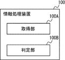
- the acquisition unit that acquires height information regarding the height of the shooting position of the shooting device that shot the image in which the user's face is detected, and the use based on the height information.
- An information processing device including a determination unit for determining whether or not a person is a candidate for a person requiring support who may be a person requiring support is provided.
- height information regarding the height of the shooting position of the shooting device that shot the image in which the user's face is detected is acquired, and based on the height information, the user can obtain the height information.
- An information processing method for determining whether or not a person is a candidate for a person requiring support who may be a person requiring support is provided.
- the computer acquires height information regarding the height of the shooting position of the shooting device that shot the image in which the user's face is detected, and based on the height information, the above-mentioned A recording medium in which a program for executing a determination as to whether or not a user is a candidate for a support-requiring person who may be a support-requiring person is provided.
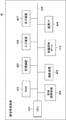
- FIG. 1 is a block diagram showing an overall configuration example of the information processing system 1 according to the present embodiment.
- the information processing system 1 is a computer system that supports a series of examination procedures for a user (traveler) U departing from an airport A in a first country to a second country by aircraft.
- the information processing system 1 is operated by, for example, a public institution such as an immigration control bureau or a trustee entrusted with the business by the institution.
- the information processing system 1 of the present embodiment detects and discovers a person who may be a person requiring support from the user U, and notifies the staff S of an alarm indicating the detection.
- a person requiring support is a person who needs the support of another person in an act, for example, a wheelchair user who uses a wheelchair, a child, or the like.
- the age range of the child to be treated as a person requiring support can be set to a predetermined age range according to the procedure contents such as 12 years old or younger, 15 years old or younger, and the like.
- the clerk S is a person who engages in or is involved in the business of the management bureau, the airline company, the airport, etc., and is, for example, the staff of the management bureau, the staff of the airline company, the staff of the airport company, and the like.
- a person who may be a person requiring support will be appropriately referred to as a candidate for a person requiring support.
- a person who does not require support that is, a person who does not need the support of another person in the act, is appropriately referred to as a person who does not need support.
- the check-in terminal 20, the staff terminal 25, the automatic baggage deposit machine 30, the security inspection device 40, the automated gate device 50, and the boarding gate device 60 are used for the common management server 10.
- Each is connected via the network NW.
- the security inspection device 40, the automated gate device 50, and the boarding gate device 60 are installed in the security area SA1 indicated by the broken line.
- the clerk terminal 25 is carried and used by the clerk S, or is installed at a predetermined place and used by the clerk S.
- the network NW is composed of a LAN (Local Area Network) including the premises communication network of Airport A, a WAN (Wide Area Network), a mobile communication network, and the like.
- the connection method is not limited to the wired method and may be a wireless method. Note that FIG. 1 illustrates only the terminal device (business terminal) used for the procedure at the time of departure at Airport A for convenience of explanation.
- the management server 10 is an information processing device that manages operations related to examination procedures at the time of entry and departure of user U. In addition, the management server 10 manages the work related to the examination procedure, detects the support-requiring candidate, and further notifies the alarm indicating the detection of the support-requiring candidate.
- the management server 10 is installed in a facility such as an airport company or an airline company that operates the airport A, for example. Further, the management server 10 may be a cloud server instead of a server installed in a facility where business is actually performed.
- the management server 10 does not have to be a single server, and may be configured as a server group including a plurality of servers. Further, as shown in FIG. 1, the examination procedure at the time of departure at Airport A is sequentially carried out at five touch points P1 to P5.
- the check-in terminal 20 is installed in the check-in lobby (hereinafter referred to as "touch point P1") in Airport A.
- the check-in terminal 20 is a self-terminal for the user U to perform the check-in procedure by himself / herself.
- the check-in procedure is a procedure for registering information for identifying a user U who is scheduled to board an aircraft. When the user U completes the procedure at the touch point P1, the user U moves to the baggage counter or the security checkpoint.
- the clerk terminal 25 is an information processing terminal used by the clerk S who is in charge of a predetermined operation in the airport A.
- the clerk terminal 25 is, for example, a mobile terminal carried and used by the clerk S.
- the staff terminal 25 may be, for example, a stationary terminal installed in a counter, an office, or the like and used by the staff S.
- the automatic baggage deposit machine 30 is installed at the baggage counter (hereinafter referred to as "touch point P2") in Airport A.
- the automatic baggage deposit machine 30 is a self-terminal for the user U to perform a procedure (baggage deposit procedure) for depositing baggage that is not brought into the aircraft by himself / herself.
- a procedure baggage deposit procedure
- the user U moves to the security checkpoint. If the user U does not check in his / her baggage, the procedure at the touch point P2 is omitted.
- the security inspection device 40 is installed at the security inspection site (hereinafter referred to as "touch point P3") in Airport A.
- the security inspection device 40 is a device that confirms whether or not the user U is wearing metals that can be dangerous substances by using a metal detector.
- the security inspection device 40 also includes an X-ray inspection device that uses X-rays to confirm the presence or absence of dangerous substances in carry-on baggage and the like.
- the user U who has completed the check-in procedure and the automatic baggage check-in procedure undergoes the security inspection procedure by the security inspection device 40 at the security checkpoint. When the user U completes the procedure at the touch point P3, the user U moves to the immigration checkpoint.
- the automated gate device 50 is installed at the immigration checkpoint (hereinafter referred to as "touch point P4") in Airport A.
- the automated gate device 50 is a device that automatically performs the departure examination procedure of the user U. When the user U completes the procedure at the touch point P4, the user U moves to the departure area where the duty-free shop and the boarding gate are provided.
- the boarding gate device 60 is a traffic control device installed for each boarding gate (hereinafter referred to as "touch point P5") in the departure area.
- the boarding gate device 60 confirms that the user U is a passenger of an aircraft that can board from the boarding gate. When the user U completes the procedure at the touch point P5, he / she boarded the aircraft and departed from the country.
- the management server 10 has a token ID information DB 11, a passage history information DB 12, a business information DB 13, a staff terminal information DB 14, and a supporter candidate information DB 15.
- the database of the management server 10 is not limited to these databases.
- FIG. 2 is a diagram showing an example of information stored in the token ID information DB 11.
- the token ID information DB 11 has a token ID, a group ID, a feature amount, a registered face image, a token issuance time, a token issuance device name, an invalid flag, and an invalidation time as data items.
- the token ID is an identifier that uniquely identifies the ID information.
- the token ID is temporarily issued on condition that the collation result of the passport face image read from the passport at the touch point P1 and the face image of the user U who holds the passport match. To. Then, when the user U completes the procedure at the touch point P5 (boarding gate), the token ID is invalidated. That is, the token ID is a one-time ID having a validity period (life cycle).
- the group ID is an identifier for grouping the ID information.
- the feature amount is a value extracted from biological information.
- the registered face image is a face image registered for the user U.
- biological information in the present embodiment means a face image and a feature amount extracted from the face image, but the biometric information is not limited to the face image and the face feature amount. That is, biometric authentication may be performed using a fingerprint image, a palm print image, an auricle image, an iris image, or the like as the biometric information of the user U.
- the token issuance time is the time when the management server 10 issues the token ID.
- the token issuing device name is the device name of the acquisition source of the registered face image that triggered the issuance of the token ID.
- the invalid flag is flag information indicating whether or not the token ID is currently valid. When the token ID is issued, the invalid flag becomes a value of "1" indicating a valid state of the token ID. Further, the invalid flag is updated to a value of "0" indicating an invalid state of the token ID when a predetermined condition is satisfied.
- the invalidation time is a time stamp when the invalidation flag is invalidated.
- FIG. 3 is a diagram showing an example of information stored in the passage history information DB 12.
- the passage history information DB 12 has a passage history ID, a token ID, a passage time, a device name, a business system type, and a passage touch point as data items.
- the passage history ID is an identifier that uniquely identifies the passage history information.
- the transit time is a time stamp when the touch point is passed.
- the device name is the machine name of the business terminal used for the procedure at the touch point.
- the business system type is the type of business system to which the business terminal belongs.
- the passing touch point is the name of the passing touch point.
- FIG. 4 is a diagram showing an example of information stored in the business information DB 13.
- the business information DB 13 contains a token ID, passenger name, reservation number, departure place, destination, airline code, flight number, operation date, seat number, nationality, passport number, surname, first name, date of birth, and gender.
- Support-required person flag and support-required person type are set as data items.
- the business information DB 13 stores business information related to a predetermined business for each token ID.
- the “predetermined work” means the procedure work performed at the touch points P1 to P5, respectively.
- the reservation number is an identifier that uniquely identifies the reservation information of the boarding pass.
- the airline code is an identifier that uniquely identifies the airline. Information such as passenger name, reservation number, departure place, destination, airline code, flight number, date of operation, seat number, nationality, passport number, surname, first name, date of birth, gender, etc. can be found on the passport and boarding.
- a passport number or reservation number can be obtained as a key from a medium such as a ticket or a database (not shown) that manages reservation information.
- the support-requiring flag is flag information indicating whether or not the user U is a support-requiring person.
- the support-requiring flag is set to a value of "1" indicating that the user U is a support-requiring person when it is confirmed that the support-requiring person is a support-requiring person. Further, the support-requiring person flag is set to a value of "0" indicating that the person does not need support when it is confirmed that the person does not need support.
- the type of person requiring support is a specific type of person requiring support such as a wheelchair user or a child when the user U is a person requiring support.
- FIG. 5 is a diagram showing an example of information stored in the staff terminal information DB 14.
- the clerk terminal information DB 14 uses the terminal ID, the clerk ID, and the current position as data items.
- the terminal ID is an identifier that uniquely identifies the staff terminal 25.
- the clerk ID is an identifier that uniquely identifies the clerk S who uses the clerk terminal 25.
- the current position is the current position of the clerk terminal 25 that is periodically or irregularly transmitted from the clerk terminal 25 to the management server 10 and registered when the clerk terminal 25 is a mobile terminal, and the clerk terminal 25 is a stationary terminal. If is, it is the location of the installation location registered in advance.
- the management server 10 can specify the current positions of a plurality of staff terminals 25 at the airport A by referring to the current positions of the staff terminal information DB 14.
- FIG. 6 is a diagram showing an example of information stored in the support-requiring candidate information DB 15.
- the support-requiring candidate information DB 15 has data items such as a candidate ID, a face image, a feature amount, a terminal ID, and a detection time.
- the candidate ID is an identifier that uniquely identifies the candidate who needs support.
- the face image is a face image of a candidate who needs support.
- the feature amount is a value extracted from the face image.
- the terminal ID is an identifier that uniquely identifies each device such as the check-in terminal 20 that has detected the face image of the candidate requiring support.
- the detection time is the time when the face image of the candidate requiring support is detected.
- FIGS. 7 to 15 a hardware configuration example of each device constituting the information processing system 1 will be described with reference to FIGS. 7 to 15. Note that the devices having the same name but different codes in FIGS. 7 to 15 have the same functions, and therefore detailed description thereof will be omitted in the subsequent drawings.
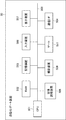
- FIG. 7 is a block diagram showing an example of the hardware configuration of the management server 10.
- the management server 10 has a CPU (Central Processing Unit) 101, a RAM (Random Access Memory) 102, a storage device 103, and a communication I / F 104. Each device is connected to a bus line 105.
- CPU Central Processing Unit
- RAM Random Access Memory
- the CPU 101 is a processor having a function of performing a predetermined operation according to a program stored in the storage device 103 and controlling each part of the management server 10.
- the CPU 101 functions as an acquisition unit, a registration unit, a issuing unit, a control unit, a collation unit, a determination unit, a notification unit, and an output unit.
- the RAM 102 is composed of a volatile storage medium and provides a temporary memory area necessary for the operation of the CPU 101.
- the storage device 103 is composed of a storage medium such as a non-volatile memory and a hard disk drive, and functions as a storage unit.
- the storage device 103 stores a program executed by the CPU 101, data referred to by the CPU 101 when the program is executed, and the like.
- the token ID information DB 11 and the like correspond to the storage unit.
- the communication I / F 104 is a communication interface based on standards such as Ethernet (registered trademark), Wi-Fi (registered trademark), and 4G, and is a module for communicating with the check-in terminal 20 and the like.
- FIG. 8 is a block diagram showing an example of the hardware configuration of the check-in terminal 20.
- the check-in terminal 20 includes a CPU 201, a RAM 202, a storage device 203, a communication I / F 204, an input device 206, a display device 207, a medium reading device 208, and a photographing device 209. Each device is connected to bus line 205.
- the input device 206 is, for example, a pointing device such as a touch panel, a keyboard, or the like.
- the display device 207 and the input device 206 are integrally formed as a touch panel.
- the display device 207 is a liquid crystal display device, an OLED (Organic Light Emitting Diode) display device, or the like, and is used for displaying moving images, still images, characters, and the like.
- the medium reading device 208 is a device that reads the passport / ticket medium of the user U and acquires the information recorded in the passport / ticket.
- the ticket medium include a paper ticket, a mobile terminal for displaying a copy of an e-ticket, and the like.
- the medium reading device 208 is composed of, for example, a code reader, an image scanner, a non-contact IC (Integrated Circuit) reader, an OCR (Optical Character Reader) device, and the like, and acquires information from various media held over the reading unit.
- the photographing device 209 is a device that acquires a face image of the user U as biological information of the user U.
- the photographing device 209 includes a first photographing device 209a and a second photographing device 209b having different heights from the floor surface to the installation position.
- the first photographing device 209a and the second photographing device 209b are, for example, digital cameras that photograph the face of the user U located in front of the check-in terminal 20, and photograph the face of the user U, respectively. Get an image.
- the height the height from a certain reference position to the installation position may be used instead of the height from the floor surface to the installation position.
- FIG. 9 is a diagram showing an example of the photographing device 209 of the check-in terminal 20.
- the first photographing device 209a is installed at a position lower than that of the second photographing device 209b.
- the first photographing device 209a and the second photographing device 209b have different photographing ranges in the vertical direction within a predetermined distance in front of the check-in terminal 20. That is, within a predetermined distance in front of the check-in terminal 20, the shooting range H1 in the vertical direction of the first shooting device 209a is lower than the shooting range H2 in the vertical direction of the second shooting device 209b (for example, the floor).
- the height from the surface to the lower end of the photographing range H1 is lower than the height from the floor surface to the lower end of the photographing range H2).
- the shooting range H1 of the first photographing device 209a is set to a predetermined height or less so that the faces of the wheelchair user Uw and the child Uc of a predetermined height or less can be photographed by the first photographing device 209a. Has been done.
- the shooting range H1 can be set as appropriate, but is set based on factors such as the average sitting height when using a wheelchair, the average height of a child in a predetermined age range to be treated as a person requiring support, and the like.
- the shooting range H2 of the second shooting device 209b is set at a position higher than a predetermined height so that the face of an adult Ua exceeding a predetermined height of the user U can be shot by the second shooting device 209b. ing. It should be noted that the photographing range H1 and the photographing range H2 may have overlapping portions.
- the check-in terminal 20 acquires height information.
- the height information is information regarding the height of the shooting position of the shooting device.
- the first photographing device 209a or the second photographing device that photographed the face image of the user U depending on whether the face image of the user U was photographed by the first photographing device 209a or the second photographing device 209b.
- Specific numerical information indicating the height of the installation position of 209b is acquired as height information.
- Acquiring the identification information of the photographing device is also included in acquiring the height information.
- the photographing device 209 is not limited to the one including the first photographing device 209a and the second photographing device 209b.
- FIG. 10 is a diagram showing another example of the photographing device 209 of the check-in terminal 20.
- the photographing device 209 may be composed of a single photographing device 209c that can be moved up and down.
- the photographing device 209c can be moved up and down to change the height.
- By changing the height of the photographing device 209c it is possible to change the photographing range H3 in the vertical direction up and down within a predetermined distance in front of the check-in terminal 20.
- height information based on the position (shooting position) of the photographing device 209c after movement can be acquired. Further, when the initial position of the photographing device 209c is determined, acquiring the amount of movement from the initial position is also included in acquiring the height information.
- the photographing device 209c can set the photographing range H3 to a predetermined height or less so that the faces of the wheelchair user Uw and the child Uc of a predetermined height or less can be photographed among the users U. Further, the photographing device 209c can set the photographing range H3 higher than the predetermined height so that the face of the adult Ua exceeding the predetermined height can be photographed among the users U. The photographing device 209c can photograph the face of the user U by appropriately changing the photographing range H3.
- FIG. 11 is a block diagram showing an example of the hardware configuration of the staff terminal 25.
- the staff terminal 25 has a CPU 251 and a RAM 252, a storage device 253, a communication I / F 254, an input device 256, a display device 257, a position sensor 258, and a magnetic sensor 259. Each device is connected to a bus line 255.
- the position sensor 258 uses GNSS (Global Navigation Satellite System) to determine the current position of the staff terminal 25. As a result, the position sensor 258 acquires the position information indicating the current position of the staff terminal 25.
- GNSS Global Navigation Satellite System
- the GNSS is not particularly limited, and examples thereof include GPS (Global Positioning System), GLONASS (Global Navigation Satellite System), Galileo, and a compass.
- the magnetic sensor 259 detects the geomagnetism at the current position of the staff terminal 25 and acquires the geomagnetic information.
- the magnetic sensor 259 is not particularly limited, but detects geomagnetism by using, for example, a Hall element, a magnetoresistive element, a magnetic impedance element, or the like.
- the clerk terminal 25 can acquire the position information indicating the current position of the clerk terminal 25 indoors based on the geomagnetic information acquired by the magnetic sensor 259.
- the staff terminal 25 can acquire the position information indicating the current position of the staff terminal 25 indoors by, for example, Wi-Fi positioning or beacon positioning.
- FIG. 12 is a block diagram showing an example of the hardware configuration of the automatic baggage deposit machine 30.
- the automatic baggage deposit machine 30 includes a CPU 301, a RAM 302, a storage device 303, a communication I / F 304, an input device 306, a display device 307, a medium reader 308, a photographing device 309, a baggage carrier 310, and a baggage carrier 310. It has an output device 311. Each device is connected to bus line 305.
- the baggage transport device 310 transports the baggage to the aircraft on which the user U is boarding.
- the baggage transfer device 310 transports the baggage attached to the baggage tag placed in the receiving unit by the user U toward the handling.
- the output device 311 is a device that outputs a baggage tag attached to checked baggage.
- the output device 311 outputs a baggage redemption certificate necessary for redeeming baggage after arriving at the destination.
- the baggage tag and baggage redemption certificate are associated with at least either passport information or boarding information.
- FIG. 13 is a block diagram showing an example of the hardware configuration of the security inspection device 40.
- the security inspection device 40 includes a CPU 401, a RAM 402, a storage device 403, a communication I / F 404, an input device 406, a display device 407, a medium reading device 408, a photographing device 409, and a metal detection gate 410. are doing. Each device is connected to bus line 405.
- the metal detection gate 410 is a gate type metal detector, and detects metals worn by the user U passing through the metal detection gate 410.
- FIG. 14 is a block diagram showing an example of the hardware configuration of the automated gate device 50.
- the automated gate device 50 includes a CPU 501, a RAM 502, a storage device 503, a communication I / F 504, an input device 506, a display device 507, a medium reading device 508, a photographing device 509, and a gate 511. Each device is connected to bus line 505.
- the automated gate device 50 located at the immigration checkpoint has the same hardware configuration as the automated gate device 50 located at the immigration checkpoint.
- the gate 511 is controlled by the CPU 501 to block the passage of the user U during standby. It shifts to the open state that allows the passage of user U.
- the method of the gate 511 is not particularly limited, and is, for example, a flapper gate that opens and closes a flapper provided from one side or both sides of the passage, a turnstile gate in which three bars rotate, and the like.
- FIG. 15 is a block diagram showing an example of the hardware configuration of the boarding gate device 60.
- the boarding gate device 60 includes a CPU 601, a RAM 602, a storage device 603, a communication I / F 604, an input device 606, a display device 607, a photographing device 609, and a gate 611. Each device is connected to bus line 605.
- [Check-in procedure] 16 and 20 are sequence diagrams showing an example of processing of the check-in terminal 20 and the management server 10. This process is executed every time the user U performs the check-in procedure using the check-in terminal 20.
- the check-in terminal 20 constantly or periodically photographs the front of the check-in terminal 20 by the first imaging device 209a and the second imaging device 209b, and the check-in terminal 20 is included in the captured image. It is determined whether or not the face of the user U located in front is detected (step S11). The check-in terminal 20 waits until the face of the user U is detected in the image by the first photographing device 209a or the second photographing device 209b (steps S11, NO).
- the check-in terminal 20 determines that the face of the user U is detected by the first photographing device 209a or the second photographing device 209b (step S11, YES)
- the check-in terminal 20 detects the face of the first photographing device 209a or the second photographing device.
- the face of the user U is photographed by 209b.
- the check-in terminal 20 acquires the face image of the user U as the target face image (step S12).
- the check-in terminal 20 transmits the target face image photographed by the first photographing device 209a or the second photographing device 209b to the management server 10 together with the height information via the network NW (step S13).
- the height information is information on the height of the installation position of the photographing device that captured the target face image, specifically, the first photographing device 209a installed at a low position or the second photographed device installed at a high position. This is information indicating that the photographing device 209b has photographed the target face image.
- the height information is information indicating, for example, the photographing height of the photographing device 209c when the face of the user U is photographed.
- the check-in terminal 20 when transmitting the target face image, the check-in terminal 20 also transmits the terminal ID, which is an identifier that uniquely identifies the check-in terminal 20, to the management server 10.
- the management server 10 can specify the position of the check-in terminal 20 based on the terminal ID of the check-in terminal 20.
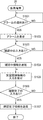
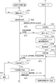
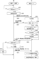
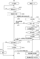
- FIG. 17 is a flowchart showing an example of processing related to a person requiring support of the management server 10.
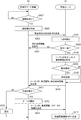
- FIG. 18 is a flowchart showing an example of the processing of the staff terminal 25 related to the processing related to the person requiring support.
- the shooting height of the shooting device that shot the user U from which the target face image was acquired is equal to or less than a predetermined height based on the height information received from the check-in terminal 20. (Step S1401).
- the management server 10 determines that the photographing height is equal to or less than a predetermined height.
- the management server 10 determines that the photographing height is not equal to or less than a predetermined height.
- the management server 10 determines whether or not the photographing height of the photographing device 209c when photographing the face of the user U is equal to or less than a predetermined height. Can be determined.
- the management server 10 determines that the shooting height is not equal to or less than the predetermined height (step S1401, NO)
- the management server 10 ends the process related to the person requiring support.
- the management server 10 determines that the shooting height is equal to or less than a predetermined height (step S1401, YES), the user U who has shot the target face image is confirmed by the staff member S as described later. It is determined whether or not the person does not need support (step S1402).
- the management server 10 collates the target face image received from the check-in terminal 20 with a plurality of registered face images registered in the token ID information DB 11 on a one-to-N basis when determining whether or not the person is a support-free person. ..
- the registered face image to be collated is limited to the image associated with the token ID whose invalid flag value is "1" (valid).
- the management server 10 finds the registered face image of the matching match as a result of the matching, the management server 10 refers to the support-requiring person flag in the business information of the business information DB 13 using the token ID associated with the registered face image as a key.
- the management server 10 determines that the user U is a support-free person.
- the management server 10 determines that the user U is not a support-requiring person.
- the management server 10 determines that the user U is a person who does not need support (step S1402, YES)
- the management server 10 ends the process related to the person requiring support.
- the management server 10 determines that the user U is not a support-requiring person (step S1402, NO), it is assumed that the user U has been detected as a support-requiring candidate, and the support-requiring candidate information is obtained as a support-requiring person.
- Register in the candidate information DB 15 step S1403.
- the support-requiring candidate information is information about a user detected as a support-requiring candidate.
- the management server 10 registers the target face image, the feature amount, the terminal ID of the check-in terminal 20, the detection time of the target face image, and the like as the support-requiring candidate information in the support-requiring candidate information DB 15 for each candidate ID ( (See FIG. 6). In the present embodiment, even for the user U whose support-requiring flag is "1", which is confirmed by the staff S to be a support-requiring person, an alarm is notified to the staff S again as a support-requiring candidate. It will be.
- the management server 10 notifies the staff terminal 25 of an alarm indicating that a candidate for a person requiring support has been detected via the network NW (step S1404).
- the alarm can include, for example, the position of the check-in terminal 20 in which the candidate for a person requiring support is detected, the terminal ID, and the like.
- the management server 10 sets the clerk terminal 25 of the notification destination to notify the alarm to the position of the check-in terminal 20 in which the candidate for support is detected. It may be limited to one or more staff terminals 25 having a predetermined positional relationship.
- the management server 10 can limit the staff terminal 25 for notifying the alarm to the staff terminal 25 located within a predetermined distance range from the position of the check-in terminal 20 in which the candidate for support is detected. Further, for example, the management server 10 limits the staff terminal 25 for notifying the alarm to the staff terminal 25 located at a position where the check-in terminal 20 in which the support-requiring candidate is detected can be seen or at a position where the check-in terminal 20 can be seen by slightly moving. You can also do it. In this way, the management server 10 can notify a specific staff terminal 25 of the plurality of staff terminals 25 of the alarm.
- the staff terminal 25 determines whether or not an alarm indicating that the support-requiring candidate has been detected has been notified from the management server 10 (step S1501) until the alarm is notified. Wait (step S1501, NO).
- the staff terminal 25 determines that the alarm has been notified from the management server 10 (step S1501, YES)
- the staff terminal 25 displays a screen for notifying the alarm on the display device 257 (step S1502).
- the staff terminal 25 can output an alarm by a message voice or a sound effect from a voice output device (not shown) instead of or in addition to displaying the screen for notifying the alarm to the display device 257.
- FIG. 19 is a diagram showing an example of an alarm notification screen for notifying an alarm displayed on the display device 257 of the staff terminal 25.
- the staff terminal 25 displays the airport A premises map 2571 on the alarm notification screen. Further, the staff terminal 25 displays a detection position mark 2572 indicating the position of the check-in terminal 20 in which a candidate for support is detected and a current position mark 2573 indicating its own current position on the premises map 2571.
- the clerk terminal 25 has a confirmation button 2574 for inputting that the clerk S is confirming whether or not the support-requiring candidate is a support-requiring person, and the clerk S confirms the confirmation.
- the staff terminal 25 displays a button group 2576 for inputting support-related information on the alarm notification screen.
- the button group 2576 is a radio button for inputting as support-related information the type of support-requiring person, such as a wheelchair or a child, depending on whether the support-requiring candidate is a support-requiring person or a support-requiring person. Includes selection buttons such as check buttons.
- the clerk S may press the checking button 2574 and input that the clerk S is confirming whether or not the support-requiring candidate is a support-requiring person. it can.
- the checking staff S can input support-related information by checking the selection button of the button group 2576.
- the clerk S who has completed the confirmation can press the confirmation completion button 2575 to input that the confirmation has been completed.
- the clerk terminal 25 displaying the alarm notification screen is input by the clerk S that the clerk S is confirming whether or not the support-requiring candidate is the support-requiring person. Wait (step S1503, NO).
- Step S1503 When the clerk terminal 25 determines that it has been input that the clerk S is checking (step S1503, YES), the clerk terminal 25 transmits the checking information indicating that the clerk S is checking to the management server 10 via the network NW. (Step S1504).
- the staff terminal 25 accepts the input of support-related information by the staff S (step S1505).
- the clerk terminal 25 waits for the clerk S to input that the clerk S has completed the confirmation of whether or not the support-requiring candidate is the support-requiring person (step S1506, NO).
- the clerk terminal 25 determines that it has been input that the clerk S has completed the confirmation (step S1506, YES)
- the clerk terminal 25 transmits the confirmation completion information indicating that the clerk S has completed the confirmation to the management server 10 via the network NW.
- the staff terminal 25 transmits the support-related information input by the staff S together with the confirmation completion information to the management server 10 via the network NW.
- the support-related information indicates whether the candidate for a person requiring support is a person requiring support or a person who does not need support, and the type of wheelchair, child, etc. in the case of a person requiring support.
- the confirmation in-confirmation information and the confirmation completion information are transmitted to the management server 10 that has notified the staff terminal 25 of the alarm according to the confirmation status of the support-requiring candidate by the staff S.
- the management server 10 that has notified the staff terminal 25 of the alarm determines whether or not the checking information has been received from the staff terminal 25 (step S1405).
- the management server 10 determines that the confirmation information has not been received (step S1405, NO)
- it further determines whether or not a predetermined time has elapsed from the alarm notification (step S1406).
- the management server 10 determines that the predetermined time has not elapsed (step S1406, NO)
- the management server 10 proceeds to step S1405 and continues to wait for the confirmation information to be received.
- the management server 10 determines that the predetermined time has elapsed (step S1406, YES)
- the management server 10 proceeds to step S1404 and notifies the staff terminal 25 of the alarm again.
- the management server 10 can expand the range of the staff terminal 25 for notifying the alarm. For example, the management server 10 can notify the alarm to the staff terminal 25 located within a distance range wider than the distance range of the staff terminal 25 that previously notified the alarm.
- the management server 10 determines that the confirmation information has been received (step S1405, YES)
- the management server 10 instructs the staff terminal 25 who has notified the alarm to stop the alarm via the network NW (step S1407).
- the staff terminal 25 instructed to stop the alarm stops displaying the alarm on the display device 257 and stops the alarm.
- the management server 10 instructed to stop the alarm subsequently determines whether or not the confirmation completion information has been received from the staff terminal 25 (step S1408).
- the management server 10 determines that the confirmation completion information has not been received (step S1408, NO)
- it further determines whether or not a predetermined time has elapsed from the instruction to stop the alarm (step S1409).
- the management server 10 determines that the predetermined time has not elapsed (step S1409, NO)
- the management server 10 proceeds to step S1408 and continues to wait for the confirmation completion information to be received.
- the management server 10 determines that the predetermined time has elapsed (step S1409, YES)
- the management server 10 proceeds to step S1404 and notifies the staff terminal 25 of the alarm again.
- the management server 10 expands the range of the staff terminal 25 for notifying the alarm, similarly to the notification of the alarm again when the predetermined time elapses in step S1406. Can be done.
- the management server 10 determines whether or not the support-requiring candidate is a support-requiring person based on the support-related information transmitted together with the confirmation completion information. Determine (step S1410).
- the management server 10 determines that it is not a support-requiring person (step S1410, NO), it deletes the support-requiring candidate information registered in the support-requiring candidate information DB 15 for the support-requiring candidate (step S1412).
- the management server 10 determines that the person needs support (step S1410, YES)
- the management server 10 acquires the support-related information and temporarily stores it (step S1411).
- the management server 10 can temporarily store support-related information in the RAM 102, the storage device 103, and the like.
- the management server 10 can register the support-requiring person flag and the support-requiring person type in the business information based on the support-related information temporarily stored.
- the management server 10 deletes the support-requiring candidate information registered in the support-requiring candidate information DB 15 for the support-requiring candidate (step S1412).
- the support-requiring candidate is detected based on the shooting height of the photographing device that captured the target face image of the user U, and the alarm is notified to the staff terminal 25 to indicate the detection of the support-requiring candidate. Then, the staff member S confirms whether or not the candidate for the person requiring support is a person requiring support.
- the support-requiring candidate is found with high accuracy and efficiency. Can be done.
- the management server 10 issues an alarm to the signage terminal installed in the vicinity of or in the vicinity of the check-in terminal 20 in which the candidate requiring support is detected, which displays guidance, advertisements, etc., in the same manner as in the case of the staff terminal 25. You can also notify. As a result, even a staff member who does not have a terminal can notice the alarm. Further, for example, the management server 10 can notify the user terminal, which is a mobile terminal carried and used by the user U detected as a candidate for a supporter, of an alarm.
- the management server 10 can specify the user terminal carried by the support-requiring candidate to be notified of the alarm, for example, based on the location information transmitted from the application executed on the user terminal. ..
- information including guidance information for example, information indicating the position of a wheelchair slope
- the support of the user U can be promoted.
- the type and amount of information to be notified to the user U can be appropriately changed according to the user U.
- the user U who has been confirmed to be a person requiring support, can subsequently perform the check-in procedure at the check-in terminal 20 while receiving support according to the required degree by the staff member S.
- the person requiring support flag indicating that he / she is a person requiring support is part of the business information, and the subsequent procedures such as baggage check-in procedure and security inspection procedure are performed. , It will be taken over by the departure examination procedure and boarding procedure. Therefore, in the subsequent procedure, the support-requiring person can be easily identified from the user U based on the support-requiring flag, and the specified support-requiring person can be supported by the staff member S. ..
- the check-in terminal 20 determines whether or not the passport of the user U is held over the reading unit (not shown) of the medium reader 208 (step S101), and waits until the passport is held. (Step S101, NO).
- the check-in terminal 20 determines that the passport is held over the reading unit of the medium reading device 208 (step S101, YES)
- the check-in terminal 20 acquires the passport information of the user U from the held passport (step S102).
- the acquired passport information includes the passport face image of the user U, the identity verification information, the passport number, the information of the passport issuing country, and the like.
- the check-in terminal 20 determines whether or not the ticket medium of the user U is held over the reading unit of the medium reading device 208 (step S103), and waits until the ticket medium is held over (step S103). , NO).
- the check-in terminal 20 determines that the ticket medium is held over the reading unit of the medium reading device 208 (step S103, YES).
- the check-in terminal 20 acquires the boarding information of the user U from the held ticket medium (step S103, YES).
- the medium reader 208 uses the ticket medium to provide the boarding information (first name, last name, airline code, flight name, boarding date, departure place (boarding airport), destination (arrival airport), and seat number of the user U. , Boarding time, arrival time, etc.) can be obtained.
- the check-in terminal 20 photographs the face of the user U with the photographing device 209, and acquires the face image as the target face image (step S105). It is preferable to display a screen for obtaining the consent of the user U before taking the face image. Further, since the check-in terminal 20 acquires the target face image of the user U by the first photographing device 209a or the second photographing device 209b in step S12, the photographing in step S105 can be omitted.
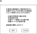
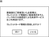
- FIG. 21 is a diagram showing an example of a screen displayed on the check-in terminal 20.
- a face image If you register your face image, you can easily perform the following procedures until departure by face recognition." And take a face image.
- a button is displayed to select whether or not to do it.
- the check-in terminal 20 transmits the captured target face image, passport information, and boarding information to the management server 10 (step S106).
- the management server 10 collates the passport face image of the user U with the target face image taken by the check-in terminal 20 on a one-to-one basis (step S107).
- the management server 10 determines that the matching result of the passport face image and the target face image is a matching match (step S108, YES)
- the management server 10 issues a token ID (step S109).
- the token ID is set to a unique value based on, for example, the date and time at the time of processing and the sequence number.
- the management server 10 registers the relationship between the token ID and the registered face image in the token ID information DB 11 with the target face image as the registered face image (step S110).
- the reason why the face image (target face image) taken locally is used as the registered face image is that the validity period (life cycle) of the token ID is completed within the day, and the photographed image is the subsequent authentication process.
- the image taken in 1 and the quality (appearance) are closer than the passport face image.
- the passport face image instead of the target face image (photographed face image), the passport face image may be set as the registered face image (registered biometric information). For example, if the token ID has a long life cycle (for example, in the aviation industry, if the member is valid for the token ID for a certain period of time, etc.), the face image of the passport or license will be used as the registered face image. It is good to set.
- the management server 10 registers the relationship between the token ID and the business information in the business information DB 13 using the passport information and the boarding information as the business information (step S111). That is, the control data required for face recognition and the business information required for business execution are managed in separate databases, but the registered face image and the business information are associated with each other by the token ID.
- the control data in the present embodiment means data including a registered face image that is collated with the target face image in face recognition and various data items such as an invalid flag associated with the token ID together with the registered face image (see FIG. 2). ).
- the management server 10 sets the support-requiring flag to "0" (support) as the business information registered in the business information DB 13 based on the support-related information. Set from (unnecessary person) to "1" (support required person). Further, the management server 10 registers the type of person requiring support such as a wheelchair or a child as business information based on the support-related information.
- the management server 10 transmits the issued token ID and the matching result information of the matching match to the check-in terminal 20 (step S112).
- the management server 10 determines that the matching result of the passport face image and the target face image is a matching mismatch (step S108, NO)
- the management server 10 transmits the matching result information of the matching mismatch to the check-in terminal 20 (step S113). ).
- the check-in terminal 20 determines that the check-in procedure can be executed based on the collation result of the collation match received from the management server 10 (step S114, YES)
- the check-in terminal 20 is based on the input information of the user U.
- Perform check-in procedures such as itinerary confirmation and seat selection (step S115).
- the check-in terminal 20 transmits the token ID, the business information, and the status information indicating the completion of the procedure at the check-in terminal 20 to the management server 10 (step S116).
- the status information includes information such as the passage time of the touch point and the device name of the terminal used.
- the management server 10 when the management server 10 receives the information from the check-in terminal 20, it registers the passage history information indicating the relationship between the token ID and the passage information of the touch point P1 in the passage history information DB 12 (step S117). Further, the management server 10 updates the business information DB 13 based on the business information received from the check-in terminal 20 as necessary.
- step S114 when the check-in terminal 20 determines that the check-in procedure cannot be executed based on the collation result of the collation mismatch received from the management server 10 (step S114, NO), the check-in terminal 20 notifies the user U of an error message. (Step S118).
- the target face image (photographed face image) that matches the passport face image obtained from the passport in the check-in procedure is registered as the registered face image in the token ID information DB 11, and the registered face image is registered by the issued token ID.
- the token ID associated with the registered face image is identification information that can be commonly used at all touch points. By using such a common token ID, the examination of the user U can be made more efficient.
- a support-requiring flag indicating that the user U is a support-requiring person is set as a part of the business information. It is possible to easily identify the person requiring support based on.
- FIG. 22 is a sequence diagram showing an example of processing by the automatic baggage deposit machine 30 and the management server 10. This process is executed when the user U who has completed the check-in procedure receives the baggage check-in procedure as necessary.
- the automatic baggage deposit machine 30 constantly or periodically photographs the front of the device, and determines whether or not the face of the user U standing in front of the automatic baggage deposit machine 30 is detected in the captured image (step S201). ). The automatic baggage deposit machine 30 waits until the face of the user U is detected in the image by the photographing device 309 (step S201, NO).
- step S201 When the automatic baggage deposit machine 30 determines that the face of the user U is detected by the photographing device 309 (step S201, YES), the automatic baggage deposit machine 30 photographs the face of the user U and sets the face image of the user U as the target face image. (Step S202).
- the automatic baggage deposit machine 30 transmits the target face image of the user U captured by the photographing device 309 to the management server 10 together with the collation request via the network NW (step S203).
- the automatic baggage deposit machine 30 collates the target face image of the user U captured by the photographing device 309 with the plurality of registered face images registered in the token ID information DB 11 of the management server 10 on a one-to-N basis. Request the management server 10 to do so.
- the management server 10 collates the face image of the user U (step S204). That is, the management server 10 collates the target face image received from the automatic baggage deposit machine 30 with the plurality of registered face images registered in the token ID information DB 11 on a one-to-N basis.
- the registered face image to be collated is limited to the image associated with the token ID whose invalid flag value is "1" (valid).
- step S205 when the management server 10 determines that the collation result is a collation mismatch (step S205, NO), the management server 10 transmits the mismatch collation result information to the automatic baggage deposit machine 30 (step S207), and the process is performed. The process proceeds to step S211. On the other hand, when the management server 10 determines that the collation result is a collation match (step S205, YES), the process proceeds to step S206.
- step S206 the management server 10 acquires business information from the business information DB 13 using the token ID associated with the registered face image of the matching match in the token ID information DB 11 as a key.
- the management server 10 determines whether or not the user U is a support-requiring person based on the support-requiring person flag included in the acquired business information (step S208).
- the support-requiring person flag is "1”
- the management server 10 determines that the support-requiring person is required, and when the support-requiring person flag is "0", the management server 10 determines that the support-requiring person is not. In this way, the management server 10 can easily identify the support-requiring person from the users U who perform the baggage check-in procedure based on the support-requiring person flag.
- the management server 10 determines that the person does not require support (step S208, NO)
- the management server 10 proceeds to the next step as it is.
- the management server 10 determines that the person needs support (step S208, YES)
- the management server 10 executes a coping process for dealing with the person requiring support (step S209), and proceeds to the next step.
- the management server 10 as a coping process, for example, the user U is a support person required for the staff terminal 25 carried by the staff S engaged in the baggage deposit procedure, the staff S engaged in the work dealing with the person requiring support, and the like. It is possible to notify an alarm indicating that. At this time, the management server 10 can notify the type of person requiring support included in the business information together with the alarm.
- the management server 10 transmits the collation result information, the token ID, and the business information to the automatic baggage deposit machine 30 (step S210).
- the management server 10 can execute step S210 and the above steps S208 and S209 regardless of the future, and can also execute the steps S210 and S209 in parallel.
- the automatic baggage deposit machine 30 determines that the procedure can be executed based on the collation result information and the business information (step S211, YES)
- the automatic baggage deposit machine 30 executes the processing of the baggage deposit procedure of the user U based on the business information. (Step S212).
- the automatic baggage deposit machine 30 transmits the token ID, the business information, and the status information indicating that the baggage deposit procedure of the user U is completed to the management server 10 via the network NW after collating the face image.
- the status information includes information such as the passage time of the touch point and the device name of the terminal used.
- the management server 10 When the management server 10 receives the information from the automatic baggage deposit machine 30, the management server 10 registers the passage history information indicating the relationship between the token ID and the passage information of the user U's touch point P2 in the passage history information DB 12 (step S214). .. Further, the management server 10 updates the business information DB 13 based on the business information received from the automatic baggage deposit machine 30 as necessary.
- the automatic baggage deposit machine 30 determines that the procedure cannot be executed based on the collation result information and the business information (step S211 and NO), the automatic baggage deposit machine 30 notifies the user U of an error message (step S215).
- FIG. 23 is a sequence diagram showing an example of processing by the security inspection device 40 and the management server 10. This process is executed when the user U who has completed the check-in procedure undergoes the security inspection procedure.
- the security inspection device 40 constantly or periodically photographs the front of the metal detection gate 410, and determines whether or not the face of the user U standing in front of the metal detection gate 410 is detected in the captured image (step). S301). The security inspection device 40 waits until the face of the user U is detected in the image by the photographing device 409 (step S301, NO).
- the security inspection device 40 determines that the face of the user U is detected by the photographing device 409 (step S301, YES)
- the security inspection device 40 photographs the face of the user U and uses the face image of the user U as the target face image. Acquire (step S302).
- the security inspection device 40 transmits the target face image of the user U captured by the photographing device 409 to the management server 10 together with the collation request via the network NW (step S303).
- the security inspection device 40 collates the target face image of the user U captured by the photographing device 409 with the plurality of registered face images registered in the token ID information DB 11 of the management server 10 on a one-to-N basis. Request the management server 10 to do so.
- the management server 10 collates the face image of the user U (step S304). That is, the management server 10 collates the target face image received from the security inspection device 40 with the plurality of registered face images registered in the token ID information DB 11 on a one-to-N basis.
- the registered face image to be collated is limited to the image associated with the token ID whose invalid flag value is "1" (valid).
- step S305 when the management server 10 determines that the collation result is a collation mismatch (step S305, NO), the management server 10 transmits the collation result information of the collation mismatch to the security inspection device 40 (step S307), and the process is performed. The process proceeds to step S311. On the other hand, when the management server 10 determines that the collation result is a collation match (step S305, YES), the process proceeds to step S306.
- step S306 the management server 10 acquires business information from the business information DB 13 using the token ID associated with the registered face image of the matching match in the token ID information DB 11 as a key.
- the management server 10 determines whether or not the user U is a support-requiring person in the same manner as in step S208 of FIG. 22 based on the support-requiring flag included in the acquired business information (step S308). In this way, the management server 10 can easily identify the support-requiring person from the users U who perform the security inspection procedure based on the support-requiring person flag.
- the management server 10 determines that the person does not require support (step S308, NO)
- the management server 10 proceeds to the next step as it is.
- the management server 10 determines that the person needs support (step S308, YES)
- the management server 10 executes a coping process for dealing with the person requiring support (step S309), and proceeds to the next step.
- the management server 10 has a user U as a supporter on a staff terminal 25 carried by, for example, a staff member S engaged in a security inspection procedure, a staff member S engaged in a business dealing with a person requiring support, and the like. It is possible to notify an alarm indicating that. At this time, the management server 10 can notify the type of person requiring support included in the business information together with the alarm.
- the management server 10 transmits the collation result information, the token ID, and the business information to the security inspection device 40 (step S310).
- the management server 10 can execute step S310 and the above steps S308 and S309 regardless of the future, and can also execute the steps S310 and S309 in parallel.
- the security inspection device 40 determines that the procedure can be executed based on the collation result information and the business information (step S311, YES).
- the security inspection device 40 executes the security inspection process of the user U based on the business information (step S311, YES).
- the CPU 401 controls each part of the security inspection device 40.
- the security inspection device 40 detects the metals worn by the user U passing through the metal detection gate 410.
- User U who has passed through the metal detection gate 410 heads for the immigration checkpoint.
- the security inspection device 40 transmits the token ID, the business information, and the status information indicating that the security inspection procedure of the user U is completed to the management server 10 via the network NW after collating the face image.
- the status information includes information such as the passage time of the touch point and the device name of the terminal used.
- the management server 10 When the management server 10 receives the information from the security inspection device 40, the management server 10 registers the passage history information indicating the relationship between the token ID and the passage information of the touch point P3 of the user U in the passage history information DB 12 (step S314). Further, the management server 10 updates the business information DB 13 based on the business information received from the security inspection device 40, if necessary.
- the security inspection device 40 determines that the procedure cannot be executed based on the collation result information and the business information (step S311, NO)
- the security inspection device 40 notifies the user U of an error message (step S315).
- FIG. 24 is a sequence diagram showing an example of processing by the automated gate device 50 and the management server 10.
- the automated gate device 50 constantly or periodically photographs the front of the automated gate device 50, and determines whether or not the face of the user U standing in front of the automated gate device 50 is detected in the captured image (step). S401). The automated gate device 50 waits until the face of the user U is detected in the image by the photographing device 509 (step S401, NO).
- step S401 determines that the face of the user U is detected by the photographing device 509 (step S401, YES)
- the automated gate device 50 photographs the face of the user U and uses the face image of the user U as the target face image. Acquire (step S402).
- the automated gate device 50 transmits the target face image of the user U captured by the photographing device 509 to the management server 10 together with the collation request via the network NW (step S403).
- the automated gate device 50 collates the target face image of the user U captured by the photographing device 509 with a plurality of registered face images registered in the token ID information DB 11 of the management server 10 on a one-to-N basis. Request the management server 10 to do so.
- the management server 10 collates the face image of the user U (step S404). That is, the management server 10 collates the target face image received from the automated gate device 50 with the plurality of registered face images registered in the token ID information DB 11 on a one-to-N basis.
- the registered face image to be collated is limited to the image associated with the token ID whose invalid flag value is "1" (valid).
- step S405, NO when the management server 10 determines that the collation result is a collation mismatch (step S405, NO), the management server 10 transmits the collation result information of the collation mismatch to the automated gate device 50 (step S407), and the process is performed. The process proceeds to step S411. On the other hand, when the management server 10 determines that the collation result is a collation match (step S405, YES), the process proceeds to step S406.
- step S406 the management server 10 acquires business information from the business information DB 13 using the token ID associated with the registered face image of the matching match in the token ID information DB 11 as a key.
- the management server 10 determines whether or not the user U is a support-requiring person in the same manner as in step S208 of FIG. 22 based on the support-requiring person flag included in the acquired business information (step S408). In this way, the management server 10 can easily identify the support-requiring person from the users U who perform the departure examination procedure based on the support-requiring person flag.
- the management server 10 determines that the person does not require support (step S408, NO)
- the management server 10 proceeds to the next step as it is.
- the management server 10 determines that the person needs support (step S408, YES)
- the management server 10 executes a coping process for dealing with the person requiring support (step S409), and proceeds to the next step.
- the management server 10 has a user U as a person requiring support on a staff terminal 25 carried by, for example, a staff member S engaged in an immigration examination procedure, a staff member S engaged in a business dealing with a person requiring support, and the like. It is possible to notify an alarm indicating that. At this time, the management server 10 can notify the type of person requiring support included in the business information together with the alarm.
- the management server 10 transmits the collation result information, the token ID, and the business information to the automated gate device 50 (step S410).
- the management server 10 can execute step S410 and the above steps S408 and S409 regardless of the future, and can also execute the steps S410 and S409 in parallel.
- step S411, YES when the automated gate device 50 determines that the procedure can be executed based on the collation result information and the business information (step S411, YES), the automated gate device 50 executes the departure examination procedure of the user U based on the business information and gates. Open 511 (step S412). The user U who has passed the touch point P4 heads for the departure area where the boarding gate is located.
- the automated gate device 50 transmits the token ID, the business information, and the status information indicating that the departure examination procedure of the user U has been completed through the matching of the face image to the management server 10 via the network NW.
- the status information includes information such as the passage time of the touch point and the device name of the terminal used.
- the management server 10 When the management server 10 receives the information from the automated gate device 50, the management server 10 registers the passing history information indicating the relationship between the token ID and the passing information of the touch point P4 of the user U in the passing history information DB 12 (step S414). Further, the management server 10 updates the business information DB 13 based on the business information received from the automated gate device 50, if necessary.
- the automated gate device 50 determines that the procedure cannot be executed based on the collation result information and the business information (step S411, NO)
- the automated gate device 50 notifies the user U of an error message (step S415).
- a notification screen including a message such as "Please perform the departure examination procedure at the manned counter" is displayed on the display device 507.
- FIG. 25 is a sequence diagram showing an example of processing of the boarding gate device 60 and the management server 10.
- the boarding gate device 60 constantly or periodically photographs the front of the device, and determines whether or not the face of the user U standing in front of the boarding gate device 60 is detected in the captured image (step S501).
- the boarding gate device 60 waits until the face of the user U is detected in the image by the photographing device 609 (step S501, NO).
- the boarding gate device 60 determines that the face of the user U is detected by the photographing device 609 (step S501, YES)
- the boarding gate device 60 photographs the face of the user U and uses the face image of the user U as the target face image. Acquire (step S502).
- the boarding gate device 60 transmits the target face image of the user U captured by the photographing device 609 to the management server 10 together with the collation request via the network NW (step S503).
- the boarding gate device 60 collates the target face image of the user U captured by the photographing device 609 with a plurality of registered face images registered in the token ID information DB 11 of the management server 10 on a one-to-N basis. Request the management server 10 to do so.
- the management server 10 When the management server 10 receives the target face image and the collation request from the boarding gate device 60, the management server 10 collates the face image of the user U (step S504). That is, the management server 10 collates the target face image received from the boarding gate device 60 with the plurality of registered face images registered in the token ID information DB 11 on a one-to-N basis.
- the registered face image to be collated is limited to the image associated with the token ID whose invalid flag value is "1" (valid).
- step S505 when the management server 10 determines that the matching result is a matching mismatch (step S505, NO), the management server 10 transmits the matching result information of the matching mismatch to the boarding gate device 60 (step S507), and the process is performed. The process proceeds to step S511. On the other hand, when the management server 10 determines that the collation result is a collation match (step S505, YES), the process proceeds to step S506.
- step S506 the management server 10 acquires business information from the business information DB 13 using the token ID associated with the registered face image of the matching match in the token ID information DB 11 as a key.
- the management server 10 determines whether or not the user U is a support-requiring person in the same manner as in step S208 of FIG. 22 based on the support-requiring flag included in the acquired business information (step S508). In this way, the management server 10 can easily identify the support-requiring person from the users U who perform the boarding procedure based on the support-requiring person flag.
- the management server 10 determines that the person does not require support (step S508, NO)
- the management server 10 proceeds to the next step as it is.
- the management server 10 determines that the person needs support (step S508, YES)
- the management server 10 executes a coping process for dealing with the person requiring support (step S509), and proceeds to the next step.
- the management server 10 as a coping process, for example, the user U is a support person required for the staff terminal 25 carried by the staff S engaged in the boarding procedure, the staff S engaged in the work dealing with the person requiring support, and the like. It is possible to notify an alarm indicating. At this time, the management server 10 can notify the type of person requiring support included in the business information together with the alarm.
- the management server 10 transmits the collation result information, the token ID, and the business information to the boarding gate device 60 (step S510).
- the management server 10 can execute step S510 and the above steps S508 and S509 regardless of the future, and can also execute the steps S510 in parallel.
- step S511, YES when the boarding gate device 60 determines that the procedure can be executed based on the collation result information and the business information (step S511, YES), the boarding gate device 60 executes the boarding procedure of the user U on the aircraft based on the business information. , Gate 611 is opened (step S512). The user U who has passed the touch point P5 board the aircraft.
- the boarding gate device 60 sends the token ID, the business information, and the status information indicating that the boarding procedure of the user U to the aircraft is completed through the collation of the face image to the management server 10 via the network NW. Transmit (step S513).
- the status information includes information such as the passage time of the touch point and the device name of the terminal used.
- the management server 10 When the management server 10 receives the information from the boarding gate device 60, the management server 10 updates the token ID information DB 11 (step S514). Specifically, the management server 10 updates the invalid flag of the token ID information DB 11 to an invalid value (“0”). As a result, the validity period (life cycle) of the token ID expires.
- the management server 10 registers the passage history information indicating the relationship between the token ID and the passage information of the touch point P5 of the user U in the passage history information DB 12 (step S515).
- the boarding gate device 60 determines that the procedure cannot be executed based on the collation result information and the business information (step S511, NO)
- the boarding gate device 60 notifies the user U of an error message (step S516).
- the boarding gate device 60 displays a notification screen including a message such as "Please perform the procedure at the manned counter" on the display device 607.
- the management server 10 associates the control data for face authentication with the business information used for various businesses by the token ID.
- the management server 10 controls the expiration of the token ID validity period at the end of a series of operations. That is, since the validity or invalidity of the association by the token ID can be easily switched, different types of databases can be associated with each other at a high security level.
- the management server 10 can expire the validity period of the token ID at the end of a series of operations. Specifically, the token ID is invalidated based on the completion of the last task (boarding procedure at the boarding gate), that is, the user U has passed through the boarding gate. Thereby, the management server 10 can limit the data association state by the token ID to the required period.
- the support-requiring candidate since the support-requiring candidate is detected and found based on the shooting height of the photographing device without requiring complicated image processing, the support-requiring candidate can be detected with high accuracy and efficiency. Can be found in. Further, according to the present embodiment, since the support-requiring flag set in the check-in procedure is carried over to the subsequent procedure, the support-requiring person can be easily identified from the user U in the subsequent procedure. ..
- FIG. 26 is a block diagram showing an overall configuration example of the information processing system 2 according to the present embodiment.
- the information processing system 2 is a computer system that supports various operations related to the operation of the theme park TP.
- the information processing system 2 has an automatic ticket vending machine 90 that sells admission tickets to the management server 10, a staff terminal 25, and an automated gate device 50 installed at the entrance / exit of the security area SA of the theme park TP.
- the POS terminal 95 installed in the security area SA are connected via the network NW.
- the clerk terminal 25 is carried and used by a clerk S such as a staff member of the theme park TP, or is installed at a predetermined place and used by the clerk S.
- the automatic ticket vending machine 90 of the present embodiment is provided at the entrance of the theme park TP, but the installation location is not limited to this.
- the automatic ticket vending machine 90 may be installed in a store such as a convenience store away from the theme park TP.
- the management server 10 in the present embodiment has the token ID information DB 11, the passage history information DB 12, the business information DB 13, the staff terminal information DB 14, and the supporter candidate information DB 15 as in the first embodiment.
- the data items of the business information stored in the business information DB 13 are also different.
- the business in the present embodiment includes a business involving commercial transactions within the theme park TP. Therefore, the business information includes payment information such as a credit card number.
- the management server 10 and the automated gate device 50 can control the entry / exit of the user U based on the face authentication even for the user U for which the payment information is not registered.
- FIG. 27 is a block diagram showing an example of the hardware configuration of the automatic ticket vending machine 90.
- the automatic ticket vending machine 90 includes a CPU 901, a RAM 902, a storage device 903, a communication I / F 904, an input device 906, a display device 907, a medium reading device 908, a photographing device 909, an automatic change machine 912, and a printer. It has 913. Each device is connected to a bus line 905.
- the automatic change machine 912 automatically issues money according to the change amount calculated by the CPU 901. It is a device that discharges to the gold mouth.
- the printer 913 prints a ticket, a receipt, a credit card usage statement, and the like on paper according to the control of the CPU 901.
- the photographing device 909 includes the first photographing device 909a and the second photographing device 909b installed at different heights, similarly to the photographing device 209 in the first embodiment.
- the imaging device 909 may be configured by a single imaging device that can move up and down, as in the imaging device 209 of the first embodiment.
- FIG. 28 is a block diagram showing an example of the hardware configuration of the POS terminal 95.
- the POS terminal 95 includes a CPU 951, a RAM 952, a storage device 953, a communication I / F 954, an input device 956, a display device 957, a medium reading device 958, a photographing device 959, an automatic change machine 962, and a printer 963. Each device is connected to bus line 955.
- FIGS. 29 and 30 are sequence diagrams showing an example of processing of the automatic ticket vending machine 90 and the management server 10. This process is executed when the user U purchases a ticket for the theme park TP at the automatic ticket vending machine 90.
- the automatic ticket vending machine 90 constantly or periodically photographs the front of the automatic ticket vending machine 90 by the first photographing device 909a and the second photographing device 909b, and the automatic ticket vending machine 90 is included in the photographed image. It is determined whether or not the face of the user U located in front is detected (step S61). The automatic ticket vending machine 90 waits until the face of the user U is detected in the image by the first photographing device 909a or the second photographing device 909b (steps S61, NO).
- the automatic ticket vending machine 90 determines that the face of the user U is detected by the first photographing device 909a or the second photographing device 909b (step S61, YES)
- the automatic ticket vending machine 90 detects the face of the first photographing device 909a or the second photographing device.
- the face of the user U is photographed by 909b.
- the automatic ticket vending machine 90 acquires the face image of the user U as the target face image (step S62).
- the automatic ticket vending machine 90 transmits the target face image photographed by the first photographing device 909a or the second photographing device 909b to the management server 10 together with the height information via the network NW (step S63).
- the height information is information on the height of the installation position of the photographing device that captured the target face image, specifically, the first photographing device 909a installed at a low position or the second photographed device installed at a high position. This is information indicating that the photographing device 909b has photographed the target face image.
- the height information is information indicating, for example, the photographing height of the photographing device when the face of the user U is photographed.
- the automatic ticket vending machine 90 when transmitting the target face image, the automatic ticket vending machine 90 also transmits the terminal ID, which is an identifier that uniquely identifies the automatic ticket vending machine 90, to the management server 10.
- the management server 10 can specify the position of the automatic ticket vending machine 90 based on the terminal ID of the automatic ticket vending machine 90.
- the management server 10 When the management server 10 receives the target face image and the height information from the automatic ticket vending machine 90, the management server 10 detects the support-requiring candidate and the like, as in the case of the first embodiment shown in FIG. Is executed (step S64). In addition, the staff terminal 25 executes the processing related to the support-requiring person-related processing as in the case of the first embodiment shown in FIG.
- the support-requiring candidate is detected based on the shooting height of the photographing device that captured the target face image of the user U, and the alarm notification indicating the detection of the support-requiring candidate to the staff terminal 25 is responded to. Then, the staff member S confirms whether or not the candidate for the person requiring support is a person requiring support. Also in this embodiment, since the support-requiring candidate is detected and found based on the shooting height of the photographing device without requiring complicated image processing, the support-requiring candidate can be found with high accuracy and efficiency. Can be done.
- the alarm notification destination is not limited to the staff terminal 25, and may be, for example, a signage terminal, a user terminal, or the like.
- the user U who has been confirmed to be a person requiring support, can subsequently perform the registration procedure at the automatic ticket vending machine 90 while receiving support according to the required degree by the staff member S. Further, for the user U who has been confirmed to be a support-requiring person, the support-requiring person flag indicating that he / she is a support-requiring person is taken over to the subsequent payment processing as a part of the business information. Therefore, in the settlement process, the support-requiring person can be easily identified from the user U based on the support-requiring person flag, and the support-requiring person S can provide support to the specified support-requiring person.
- the automatic ticket vending machine 90 acquires the payment information for purchasing the ticket (step S601)
- the automatic ticket vending machine 90 transmits the payment information to the management server 10 (step S602).
- the management server 10 executes a ticket purchase process (payment process) with a server of a payment system (not shown) based on the received payment information (step S603).
- the automatic ticket vending machine 90 determines whether or not there is consent from the user U regarding the acquisition of the face image.
- the automatic ticket vending machine 90 determines that there is consent from the user U (step S604, YES)
- the automatic ticket vending machine 90 acquires the face image of the user U taken by the photographing device 909 as a registered face image (step S604, YES). S605)
- the process proceeds to step S606.
- the automatic ticket vending machine 90 determines that there is no consent from the user U (step S604, NO)
- the process proceeds to step S613. Since the automatic ticket vending machine 90 acquires the target face image of the user U by the first photographing device 909a or the second photographing device 909b in step S62, the photographing in step S605 can be omitted.
- step S606 it is determined whether or not there is consent from the user U regarding the registration of payment information.
- the automatic ticket vending machine 90 determines that there is consent from the user U (step S606, YES)
- the automatic ticket vending machine 90 transmits the face image (registered face image) of the user U and the consent information to the management server 10. (Step S607), the process proceeds to step S609.
- the automatic ticket vending machine 90 determines that there is no consent from the user U (step S606, NO)
- only the face image is transmitted to the management server 10 (step S608), and the process proceeds to step S609. Transition.
- FIG. 31 is a diagram showing an example of a screen displayed on the automatic ticket vending machine 90.
- the explanation about taking a face image ("Customers who have registered a face image, if you register your credit card information, you can use the payment service by face recognition in the park. Register your credit card information. Do you want to do it? ”) And a button for selecting whether or not to register the payment information is displayed.
- step S609 when the management server 10 receives the information from the automatic ticket vending machine 90, it issues a token ID.
- the management server 10 registers the relationship between the token ID and the registered face image in the token ID information DB 11 (step S610).
- the management server 10 registers the relationship between the token ID and the business information (including payment information) in the business information DB 13 (step S611). As a result, the registered face image and business information such as payment information are associated with each other by the token ID. If there is no agreement regarding the association of payment information, the association with payment information is omitted.
- the validity period of the token ID in this embodiment is determined by the type of purchased ticket (one-day ticket, annual passport, etc.). For example, when the ticket type is a one-day ticket, the token ID invalid flag is set to an invalid value (“0”) at the end time of business hours on the admission date or when leaving the theme park TP. You just have to control it. That is, the management server 10 expires the validity period of the token ID based on the exit information of the user U from the area where the business is executed.
- the support-required person flag is set as the business information registered in the business information DB 13 based on the support-related information. Set from 0 "(support-free person) to" 1 "(support-required person). Further, the management server 10 registers the type of person requiring support such as a wheelchair or a child as business information based on the support-related information.
- the management server 10 transmits the processing result information including the issued token ID to the automatic ticket vending machine 90 (step S612).
- step S613 the automatic ticket vending machine 90 determines whether or not the ticket can be issued.
- the automatic ticket vending machine 90 determines that the ticket can be issued (step S613, YES)
- the automatic ticket vending machine 90 prints the ticket (step S614).
- step S613 NO the automatic ticket vending machine 90 notifies that the ticket purchase process has failed.
- FIG. 32 is a sequence diagram showing an example of processing of the POS terminal 95 and the management server 10. This process is executed when the payment method by face authentication is specified by the user U at the time of purchasing the product or the like in the theme park TP.
- the POS terminal 95 determines whether or not the face of the user U standing in front of the POS terminal 95 is detected in the image taken in front of the device (step S701). The POS terminal 95 waits until the face of the user U is detected in the image by the photographing device 959 (step S701, NO).
- step S701 When the POS terminal 95 determines that the face of the user U is detected by the photographing device 959 (step S701, YES), the POS terminal 95 photographs the face of the user U and acquires the face image of the user U as the target face image. (Step S702).
- the POS terminal 95 transmits the target face image of the user U captured by the photographing device 959 to the management server 10 together with the collation request via the network NW (step S703).
- the POS terminal 95 collates the target face image of the user U captured by the photographing device 959 with the plurality of registered face images registered in the token ID information DB 11 of the management server 10 on a one-to-N basis. Is requested from the management server 10.
- the management server 10 When the management server 10 receives the target face image and the collation request from the POS terminal 95, the management server 10 collates the face image of the user U (step S704). That is, the management server 10 collates the target face image received from the POS terminal 95 with the plurality of registered face images registered in the token ID information DB 11 on a one-to-N basis.
- the registered face image of the collation destination is limited to the image associated with the token ID whose invalid flag value is "1" (valid).
- step S705 when the management server 10 determines that the collation result is a collation mismatch (step S705, NO), the management server 10 transmits the collation result information of the collation mismatch to the POS terminal 95 (step S707), and the process is a step. Move to S711.
- step S705 when the management server 10 determines that the collation result is a collation match (step S705, YES), the process proceeds to step S706.
- step S706 the management server 10 acquires payment information included in the business information from the business information DB 13 using the token ID associated with the registered face image of the matching match as a key.
- the management server 10 determines whether or not the user U is a support-requiring person, as in the first embodiment, based on the support-requiring person flag included in the acquired business information (step S708). In this way, the management server 10 can easily identify the support-requiring person from the users U who receive the payment processing based on the support-requiring person flag.
- step S708 NO the management server 10 determines that the person does not require support
- step S708, YES the management server 10 executes a coping process for dealing with the person requiring support (step S709), and proceeds to the next step.
- the management server 10 as a coping process, for example, the user U is required to support the staff terminal 25 carried by the staff S engaged in the sales business of products and the like, the staff S engaged in the business dealing with the person requiring support, and the like. It is possible to notify an alarm indicating that. At this time, the management server 10 can notify the type of person requiring support included in the business information together with the alarm.
- the management server 10 transmits the collation result information, the token ID, and the payment information to the POS terminal 95 (step S710).
- the management server 10 can execute step S710 and the above steps S708 and S709 regardless of the future, and can also execute the steps S710 and the above steps S708 and S709 in parallel.
- step S711 when the POS terminal 95 determines that the payment process can be executed based on the collation result information and the payment information acquired from the management server 10 (step S711, YES), the payment process of the user U is performed based on the payment information. Is executed (step S712).
- the POS terminal 95 transmits the token ID and purchase information such as products to the management server 10 via the network NW (step S713).
- the management server 10 When the management server 10 receives the information from the POS terminal 95, the management server 10 updates the business information DB 13 and the passage history information DB 12, respectively (steps S714 and S715).
- the POS terminal 95 determines that the payment process cannot be executed based on the collation result information and the payment information (step S711, NO)
- the POS terminal 95 notifies the user U of an error message (step S716).
- the payment processing by face authentication becomes possible during the period when the token ID is valid.
- FIG. 33 is a block diagram showing an overall configuration example of the information processing apparatus 100 according to the present embodiment.
- the information processing device 100 requires support from the acquisition unit 100A that acquires height information regarding the height of the shooting position of the shooting device that shot the image in which the user's face is detected, and the user based on the height information. It has a determination unit 100B for determining whether or not it is a candidate for a person requiring support who may be a person. According to the information processing device 100 in the present embodiment, it is possible to efficiently find a candidate for a person requiring support with high accuracy.
- the present invention is not limited to this.
- a photographing device is configured in the same manner as the check-in terminal 20, and support is required as in the case of the check-in terminal 20. Candidates can be detected.
- the present invention is applied to business in an airport facility and a theme park has been described.
- the control data required for face recognition and the business information necessary for executing the business are managed in separate databases, and the registered face image and the business information are associated with each other by the token ID.
- the configuration of the present invention that the token ID can be easily associated with the business information of the existing business system can be applied to business in any industry such as railway, accommodation industry, service industry, and manufacturing industry.
- the purchase of products in the facility, the use of services, and the use of guest rooms Entry / exit control can be performed by face recognition during the user's accommodation period.
- the management server 10 transfers the face image to the management server 10.
- a token ID can be issued when registering.
- the user U can enter the station yard by face recognition at the automatic ticket gate and board a predetermined train.
- the conductor may take a face image of the user U using a portable business terminal and upload it to the management server 10 via the network NW. .. This enables ticket inspection work based on face recognition on the train.
- the ticket inspection may be automatically performed by the management server 10 based on an image taken by a network camera installed in the vehicle.
- the user U gets off at the destination station, he / she can leave by face recognition at the automatic ticket gate at the getting-off station, as at the time of entry. Further, if the token ID and the payment information are associated in advance, the boarding fee can be paid by face authentication. As described above, according to the present invention, there is an advantage that the face recognition function can be easily implemented in the existing business system.
- the management server 10 controls the life cycle of the token ID and the life cycle of the business information to be synchronized has been described, but the case is so as to be asynchronous. You may control it.
- the management server 10 tokenizes the reception of a face image from a user terminal such as a smartphone as a trigger. An ID is issued, and the relationship between the face image of the user U and the token ID is registered in the token ID information DB 11.
- the management server 10 registers the relationship between the issued token ID and the business information in the business information DB 13 at the timing when the user U reserves or purchases the boarding pass, for example. Then, during the period when the user U is a mileage member, the management server 10 keeps the value of the invalid flag of the token ID valid (“1”). As a result, the validity period of the token ID is not affected by the progress status (start and end) of the business. That is, unlike the case of the first embodiment, the token ID is not invalidated even if the user U passes through the boarding gate. Therefore, the user U can perform various procedures (check-in procedure-boarding procedure for an aircraft, etc.) at airport A by face recognition while he / she is registered as a member. As a result, the convenience of the user U can be improved.
- FIG. 34 is a block diagram showing an overall configuration example of the information processing system 3 in the modified embodiment.
- the ID issuing terminal 70 of the token ID, the automated gate device 50, and the automatic customs gate device 80 are arranged in the security area SA2 at the time of entry indicated by the broken line.
- the ID issuing terminal 70 applies for the issuance of a token ID by reading the passport face image and taking the face image of the user U, as in the case of the check-in terminal 20, the subsequent automated gate
- the procedures (immigration procedure and customs procedure) in the device 50 and the automatic customs gate device 80 can be executed by face recognition.
- the application for issuance of the token ID at the time of entry may be made not only from the ID issuing terminal 70 but also from the automated gate device 50 and the automatic customs gate device 80. That is, the management server 10 may acquire the passport face image and the target biological image from any one of the business terminals that execute the business related to the entry of the user U.
- each of the ID issuing terminal 70, the automated gate device 50, and the automatic customs gate device 80 also has a photographing device configured in the same manner as the check-in terminal 20, and is a candidate for a person requiring support in the same manner as in the case of the check-in terminal 20. Can be detected.
- the configuration of the present invention can be applied not only to international flights but also to domestic flights.
- domestic flights in addition to the departure examination procedure, the one-to-one matching process between the passport face image and the photographed face image may be omitted.
- the registered biological image for example, the photographed face image at the time of purchasing the boarding pass may be registered.
- the aircraft can be boarded at Airport A by face authentication.
- the check-in terminal 20 applies for the issuance of the token ID to the management server 10 by reading the passport face image from the passport, but consider the case where the check-in procedure is performed online.
- the issuance application can be made at the automatic baggage deposit machine 30 or the security inspection device 40. That is, the management server 10 acquires the passport face image and the target biological image from any one of the business terminals that execute the business related to the departure of the user U.
- a token ID will be issued by the check-in procedure in the first country, and the relevant information will be issued.
- the business information associated with the token ID can be easily used by face recognition even in immigration and customs inspections in a second country.
- the first imaging device 209a and the second imaging device 209b having different heights from the floor surface to the installation position have been described as imaging devices.
- the height from the floor surface to the installation position is the same, that is, the photographing device 209d (shooting range H4 in the vertical direction) (not shown) and the photographing device 209e (shooting range H5 in the vertical direction) (not shown) installed side by side.
- the height of the shooting range H4 is higher than the height of the shooting range H5 (for example, the height from the floor surface to the lower end of the shooting range H4 is the height from the floor surface to the lower end of the shooting range H5).
- the photographing device 209e By tilting the photographing device 209e downward so as to be higher than the height, the height of the photographing range H4 and the height of the photographing range H5 can be made different.
- acquiring the identification information of the photographing apparatus 209d or 209e is included in acquiring the height information.
- Each embodiment also has a processing method in which a program for operating the configuration of the embodiment is recorded on a recording medium so as to realize the functions of the above-described embodiment, the program recorded on the recording medium is read out as a code, and the program is executed by a computer. It is included in the category of. That is, a computer-readable recording medium is also included in the scope of each embodiment. Further, not only the recording medium on which the above-mentioned program is recorded but also the program itself is included in each embodiment.
- the recording medium for example, a floppy (registered trademark) disk, a hard disk, an optical disk, a magneto-optical disk, a CD-ROM, a magnetic tape, a non-volatile memory card, or the like can be used.
- a floppy (registered trademark) disk for example, a hard disk, an optical disk, a magneto-optical disk, a CD-ROM, a magnetic tape, a non-volatile memory card, or the like
- the program that executes the processing by the program recorded on the recording medium alone, but also the one that operates on the OS and executes the processing in cooperation with the functions of other software and the expansion board is also in each embodiment. It is included in the category of.
- An acquisition unit that acquires height information regarding the height of the shooting position of the shooting device that shot the image in which the user's face is detected, and the acquisition unit.
- An information processing device having a determination unit for determining whether or not the user is a candidate for a supporter who may be a supporter based on the height information.
- Appendix 2 The information processing device according to Appendix 1, wherein the determination unit determines that the user is a candidate for a person requiring support when the height of the shooting position of the shooting device is equal to or less than a predetermined height.
- the photographing device includes a first photographing device and a second photographing device installed at a position higher than that of the first photographing device.
- the information processing apparatus according to Appendix 2, wherein the determination unit determines that the user is a candidate for a person requiring support when the image is captured by the first imaging device.
- the imaging device can be moved up and down to change its height.
- the information processing device according to Appendix 2, wherein the determination unit determines that the user is a candidate for a person requiring support when the imaging device captures the image at the height equal to or lower than the predetermined height.
- Appendix 5 Described in any of Appendix 1 to 4 having a notification unit for notifying the notification destination of an alarm indicating that the support-requiring candidate has been detected when the user is determined to be the support-requiring candidate.
- Information processing equipment
- Appendix 6 The information processing device according to Appendix 5, wherein the notification unit notifies the alarm to the notification destination having a predetermined positional relationship with the position where the support-requiring candidate is detected.
- Appendix 7 The information processing device according to Appendix 6 for notifying the alarm to the notification destination located within a predetermined distance range from the position where the support-requiring candidate is detected.
- Appendix 11 The information processing device according to Appendix 10, wherein when the registration unit receives information indicating that the confirmation of whether or not the support-requiring candidate is the support-requiring person has been completed, the information processing device deletes the information about the user.
- Appendix 12 It has a issuing department that issues an identifier that associates the registered biometric information of the user with business information related to a predetermined business.
- the information processing device according to any one of Supplementary note 1 to 11, wherein the business information includes information indicating whether or not the user is the person requiring support.
- (Appendix 14) Acquires height information regarding the height of the shooting position of the shooting device that shot the image in which the user's face is detected. An information processing method for determining whether or not the user is a candidate for a supporter who may be a supporter based on the height information.
- NW ⁇ ⁇ ⁇ Network 1,2,3 ⁇ ⁇ ⁇ Information processing system 10 ⁇ ⁇ ⁇ Management server 11 ⁇ ⁇ ⁇ Token ID information DB 12 ... Passage history information DB 13 ... Business information DB 14 ... Staff terminal information DB 15 ... Supporter candidate information DB 20 ... Check-in terminal 25 ... Staff terminal 30 ... Automatic baggage deposit machine 40 ... Security inspection device 50 ... Automated gate device 60 ... Boarding gate device 70 ... ID issuing terminal 80 ... Automatic customs gate device 90 ... Automatic ticket vending machine 95 ... POS terminal 100 ... Information processing device
Landscapes
- Engineering & Computer Science (AREA)
- Physics & Mathematics (AREA)
- General Physics & Mathematics (AREA)
- Theoretical Computer Science (AREA)
- Multimedia (AREA)
- General Health & Medical Sciences (AREA)
- Oral & Maxillofacial Surgery (AREA)
- Health & Medical Sciences (AREA)
- Human Computer Interaction (AREA)
- Business, Economics & Management (AREA)
- Emergency Management (AREA)
- Computer Vision & Pattern Recognition (AREA)
- Management, Administration, Business Operations System, And Electronic Commerce (AREA)
- Image Analysis (AREA)
- Devices For Checking Fares Or Tickets At Control Points (AREA)
Priority Applications (6)
| Application Number | Priority Date | Filing Date | Title |
|---|---|---|---|
| BR112022004629A BR112022004629A2 (pt) | 2019-09-27 | 2019-09-27 | Dispositivo de processamento de informação, método de processamento de informação e meio de armazenamento |
| JP2021548297A JP7264265B2 (ja) | 2019-09-27 | 2019-09-27 | 情報処理装置、情報処理方法及びプログラム |
| PCT/JP2019/038338 WO2021059526A1 (ja) | 2019-09-27 | 2019-09-27 | 情報処理装置、情報処理方法及び記録媒体 |
| EP19946509.7A EP4036846A4 (en) | 2019-09-27 | 2019-09-27 | DEVICE AND METHOD FOR PROCESSING INFORMATION AS WELL AS RECORDING MEDIUM |
| US17/761,305 US12223765B2 (en) | 2019-09-27 | 2019-09-27 | Information processing apparatus, information processing method and storage medium |
| US19/001,839 US20250140018A1 (en) | 2019-09-27 | 2024-12-26 | Information processing apparatus, information processing method and storage medium |
Applications Claiming Priority (1)
| Application Number | Priority Date | Filing Date | Title |
|---|---|---|---|
| PCT/JP2019/038338 WO2021059526A1 (ja) | 2019-09-27 | 2019-09-27 | 情報処理装置、情報処理方法及び記録媒体 |
Related Child Applications (2)
| Application Number | Title | Priority Date | Filing Date |
|---|---|---|---|
| US17/761,305 A-371-Of-International US12223765B2 (en) | 2019-09-27 | 2019-09-27 | Information processing apparatus, information processing method and storage medium |
| US19/001,839 Continuation US20250140018A1 (en) | 2019-09-27 | 2024-12-26 | Information processing apparatus, information processing method and storage medium |
Publications (1)
| Publication Number | Publication Date |
|---|---|
| WO2021059526A1 true WO2021059526A1 (ja) | 2021-04-01 |
Family
ID=75165225
Family Applications (1)
| Application Number | Title | Priority Date | Filing Date |
|---|---|---|---|
| PCT/JP2019/038338 Ceased WO2021059526A1 (ja) | 2019-09-27 | 2019-09-27 | 情報処理装置、情報処理方法及び記録媒体 |
Country Status (5)
| Country | Link |
|---|---|
| US (2) | US12223765B2 (https=) |
| EP (1) | EP4036846A4 (https=) |
| JP (1) | JP7264265B2 (https=) |
| BR (1) | BR112022004629A2 (https=) |
| WO (1) | WO2021059526A1 (https=) |
Cited By (2)
| Publication number | Priority date | Publication date | Assignee | Title |
|---|---|---|---|---|
| JP7100819B1 (ja) * | 2022-01-26 | 2022-07-14 | 日本電気株式会社 | 端末、システム、端末の制御方法及びプログラム |
| WO2023007714A1 (ja) | 2021-07-30 | 2023-02-02 | 日本電気株式会社 | 認証システム及び撮像装置 |
Families Citing this family (2)
| Publication number | Priority date | Publication date | Assignee | Title |
|---|---|---|---|---|
| JP7211399B2 (ja) * | 2020-06-25 | 2023-01-24 | 横河電機株式会社 | 装置、方法およびプログラム |
| EP4310766A1 (en) * | 2021-03-17 | 2024-01-24 | NEC Corporation | Information processing device, information processing method, and recording medium |
Citations (8)
| Publication number | Priority date | Publication date | Assignee | Title |
|---|---|---|---|---|
| JPH0140906B2 (https=) * | 1983-03-11 | 1989-09-01 | Sumitomo Metal Ind | |
| WO2002056251A1 (en) | 2000-12-27 | 2002-07-18 | Mitsubishi Denki Kabushiki Kaisha | Image processing device and elevator mounting it thereon |
| JP2004310197A (ja) * | 2003-04-02 | 2004-11-04 | Casio Comput Co Ltd | 画像データ処理システム及びプログラム |
| JP2008040937A (ja) * | 2006-08-09 | 2008-02-21 | Nikon Corp | 施設内監視システム |
| JP2010238179A (ja) | 2009-03-31 | 2010-10-21 | Sogo Keibi Hosho Co Ltd | 監視装置及び監視方法 |
| JP2014241553A (ja) * | 2013-06-12 | 2014-12-25 | 株式会社Pfu | 情報端末装置、自動調整方法及び自動調整プログラム |
| JP2018109935A (ja) * | 2016-12-28 | 2018-07-12 | グローリー株式会社 | 顔照合装置及び顔照合方法 |
| JP2018173693A (ja) * | 2017-03-31 | 2018-11-08 | 日本電気株式会社 | 移動支援システム、移動支援装置、移動支援方法および移動支援プログラム |
Family Cites Families (16)
| Publication number | Priority date | Publication date | Assignee | Title |
|---|---|---|---|---|
| JP5170130B2 (ja) | 2010-03-09 | 2013-03-27 | オムロン株式会社 | 身長推定装置 |
| US9235754B2 (en) * | 2011-03-28 | 2016-01-12 | Nec Corporation | Person tracking device, person tracking method, and non-transitory computer readable medium storing person tracking program |
| US9256720B2 (en) * | 2011-05-18 | 2016-02-09 | Nextgenid, Inc. | Enrollment kiosk including biometric enrollment and verification, face recognition and fingerprint matching systems |
| CN113038020B (zh) * | 2016-10-14 | 2023-07-11 | 深圳市大疆创新科技有限公司 | 用于时刻捕获的系统和方法 |
| CA3045286C (en) * | 2016-10-28 | 2024-02-20 | Axon Enterprise, Inc. | Systems and methods for supplementing captured data |
| JP2018077740A (ja) | 2016-11-11 | 2018-05-17 | 菊一 西 | 交通弱者対応横断歩道信号システム。 |
| WO2019097680A1 (ja) | 2017-11-17 | 2019-05-23 | 三菱電機株式会社 | 人物表示制御装置、人物表示制御システム及び人物表示制御方法 |
| JP7153205B2 (ja) * | 2018-10-11 | 2022-10-14 | 日本電気株式会社 | 情報処理装置、情報処理方法及びプログラム |
| EP3879419B1 (en) * | 2018-11-05 | 2026-01-28 | NEC Corporation | Information processing device, information processing method, and recording medium |
| JP6781413B2 (ja) * | 2018-11-21 | 2020-11-04 | 日本電気株式会社 | 情報処理装置 |
| JP2020119284A (ja) * | 2019-01-24 | 2020-08-06 | 日本電気株式会社 | 情報処理装置、情報処理方法及びプログラム |
| US12293312B2 (en) * | 2020-03-17 | 2025-05-06 | Nec Corporation | Visit assistance device, visit assistance system, visit assistance method, and non-transitory computer-readable medium having program stored therein |
| WO2021199158A1 (ja) * | 2020-03-30 | 2021-10-07 | 日本電気株式会社 | 情報処理装置、情報処理方法及び記録媒体 |
| JP6819916B1 (ja) * | 2020-03-31 | 2021-01-27 | 日本電気株式会社 | 情報処理装置、情報処理方法及びプログラム |
| JP7626196B2 (ja) * | 2021-03-15 | 2025-02-04 | 日本電気株式会社 | 情報処理装置、情報処理方法、プログラム |
| JP2023061142A (ja) * | 2021-10-19 | 2023-05-01 | 株式会社リコー | 情報処理装置、情報処理方法、及びプログラム |
-
2019
- 2019-09-27 JP JP2021548297A patent/JP7264265B2/ja active Active
- 2019-09-27 WO PCT/JP2019/038338 patent/WO2021059526A1/ja not_active Ceased
- 2019-09-27 US US17/761,305 patent/US12223765B2/en active Active
- 2019-09-27 BR BR112022004629A patent/BR112022004629A2/pt unknown
- 2019-09-27 EP EP19946509.7A patent/EP4036846A4/en not_active Withdrawn
-
2024
- 2024-12-26 US US19/001,839 patent/US20250140018A1/en active Pending
Patent Citations (8)
| Publication number | Priority date | Publication date | Assignee | Title |
|---|---|---|---|---|
| JPH0140906B2 (https=) * | 1983-03-11 | 1989-09-01 | Sumitomo Metal Ind | |
| WO2002056251A1 (en) | 2000-12-27 | 2002-07-18 | Mitsubishi Denki Kabushiki Kaisha | Image processing device and elevator mounting it thereon |
| JP2004310197A (ja) * | 2003-04-02 | 2004-11-04 | Casio Comput Co Ltd | 画像データ処理システム及びプログラム |
| JP2008040937A (ja) * | 2006-08-09 | 2008-02-21 | Nikon Corp | 施設内監視システム |
| JP2010238179A (ja) | 2009-03-31 | 2010-10-21 | Sogo Keibi Hosho Co Ltd | 監視装置及び監視方法 |
| JP2014241553A (ja) * | 2013-06-12 | 2014-12-25 | 株式会社Pfu | 情報端末装置、自動調整方法及び自動調整プログラム |
| JP2018109935A (ja) * | 2016-12-28 | 2018-07-12 | グローリー株式会社 | 顔照合装置及び顔照合方法 |
| JP2018173693A (ja) * | 2017-03-31 | 2018-11-08 | 日本電気株式会社 | 移動支援システム、移動支援装置、移動支援方法および移動支援プログラム |
Non-Patent Citations (1)
| Title |
|---|
| See also references of EP4036846A4 |
Cited By (6)
| Publication number | Priority date | Publication date | Assignee | Title |
|---|---|---|---|---|
| WO2023007714A1 (ja) | 2021-07-30 | 2023-02-02 | 日本電気株式会社 | 認証システム及び撮像装置 |
| US12147515B2 (en) | 2021-07-30 | 2024-11-19 | Nec Corporation | Authentication system and imaging apparatus |
| JP7100819B1 (ja) * | 2022-01-26 | 2022-07-14 | 日本電気株式会社 | 端末、システム、端末の制御方法及びプログラム |
| WO2023144912A1 (ja) * | 2022-01-26 | 2023-08-03 | 日本電気株式会社 | 端末、システム、端末の制御方法及び記憶媒体 |
| JP2023109132A (ja) * | 2022-01-26 | 2023-08-07 | 日本電気株式会社 | 端末、端末の制御方法及びプログラム |
| JP7392771B2 (ja) | 2022-01-26 | 2023-12-06 | 日本電気株式会社 | 端末、端末の制御方法及びプログラム |
Also Published As
| Publication number | Publication date |
|---|---|
| JPWO2021059526A1 (https=) | 2021-04-01 |
| US20250140018A1 (en) | 2025-05-01 |
| US20220343673A1 (en) | 2022-10-27 |
| JP7264265B2 (ja) | 2023-04-25 |
| EP4036846A4 (en) | 2022-10-12 |
| BR112022004629A2 (pt) | 2022-05-31 |
| US12223765B2 (en) | 2025-02-11 |
| EP4036846A1 (en) | 2022-08-03 |
Similar Documents
| Publication | Publication Date | Title |
|---|---|---|
| JP7482381B2 (ja) | 情報処理装置、情報処理方法及び記録媒体 | |
| JP7544175B2 (ja) | 情報処理装置、情報処理方法及び記録媒体 | |
| JP7031798B2 (ja) | プログラム、情報処理装置及び情報処理方法 | |
| JP7622711B2 (ja) | 情報処理装置、情報処理方法及び記録媒体 | |
| JP7045646B2 (ja) | 情報処理装置、情報処理方法及びプログラム | |
| JP7537535B2 (ja) | 情報処理装置、情報処理方法及びプログラム | |
| JP7540521B2 (ja) | 情報処理装置、情報処理方法及びプログラム | |
| JP7264265B2 (ja) | 情報処理装置、情報処理方法及びプログラム | |
| JPWO2020138348A1 (ja) | 情報処理装置、情報処理方法及びプログラム | |
| JPWO2020138349A1 (ja) | 情報処理装置、情報処理方法及びプログラム | |
| JP7279784B2 (ja) | 情報処理装置、情報処理方法及びプログラム | |
| WO2021064880A1 (ja) | 情報処理装置、情報処理方法及び記録媒体 |
Legal Events
| Date | Code | Title | Description |
|---|---|---|---|
| 121 | Ep: the epo has been informed by wipo that ep was designated in this application |
Ref document number: 19946509 Country of ref document: EP Kind code of ref document: A1 |
|
| ENP | Entry into the national phase |
Ref document number: 2021548297 Country of ref document: JP Kind code of ref document: A |
|
| REG | Reference to national code |
Ref country code: BR Ref legal event code: B01A Ref document number: 112022004629 Country of ref document: BR |
|
| NENP | Non-entry into the national phase |
Ref country code: DE |
|
| WWE | Wipo information: entry into national phase |
Ref document number: 2019946509 Country of ref document: EP |
|
| ENP | Entry into the national phase |
Ref document number: 2019946509 Country of ref document: EP Effective date: 20220428 |
|
| ENP | Entry into the national phase |
Ref document number: 112022004629 Country of ref document: BR Kind code of ref document: A2 Effective date: 20220314 |