WO2021053983A1 - 全固体電池、正極および全固体電池製造方法 - Google Patents
全固体電池、正極および全固体電池製造方法 Download PDFInfo
- Publication number
- WO2021053983A1 WO2021053983A1 PCT/JP2020/029716 JP2020029716W WO2021053983A1 WO 2021053983 A1 WO2021053983 A1 WO 2021053983A1 JP 2020029716 W JP2020029716 W JP 2020029716W WO 2021053983 A1 WO2021053983 A1 WO 2021053983A1
- Authority
- WO
- WIPO (PCT)
- Prior art keywords
- solid
- positive electrode
- electrode layer
- state battery
- solid electrolyte
- Prior art date
- Legal status (The legal status is an assumption and is not a legal conclusion. Google has not performed a legal analysis and makes no representation as to the accuracy of the status listed.)
- Ceased
Links
Images

Classifications
-
- C—CHEMISTRY; METALLURGY
- C01—INORGANIC CHEMISTRY
- C01B—NON-METALLIC ELEMENTS; COMPOUNDS THEREOF; METALLOIDS OR COMPOUNDS THEREOF NOT COVERED BY SUBCLASS C01C
- C01B25/00—Phosphorus; Compounds thereof
- C01B25/16—Oxyacids of phosphorus; Salts thereof
- C01B25/26—Phosphates
- C01B25/45—Phosphates containing plural metal, or metal and ammonium
-
- H—ELECTRICITY
- H01—ELECTRIC ELEMENTS
- H01M—PROCESSES OR MEANS, e.g. BATTERIES, FOR THE DIRECT CONVERSION OF CHEMICAL ENERGY INTO ELECTRICAL ENERGY
- H01M10/00—Secondary cells; Manufacture thereof
- H01M10/05—Accumulators with non-aqueous electrolyte
- H01M10/052—Li-accumulators
-
- H—ELECTRICITY
- H01—ELECTRIC ELEMENTS
- H01M—PROCESSES OR MEANS, e.g. BATTERIES, FOR THE DIRECT CONVERSION OF CHEMICAL ENERGY INTO ELECTRICAL ENERGY
- H01M10/00—Secondary cells; Manufacture thereof
- H01M10/05—Accumulators with non-aqueous electrolyte
- H01M10/056—Accumulators with non-aqueous electrolyte characterised by the materials used as electrolytes, e.g. mixed inorganic/organic electrolytes
- H01M10/0561—Accumulators with non-aqueous electrolyte characterised by the materials used as electrolytes, e.g. mixed inorganic/organic electrolytes the electrolyte being constituted of inorganic materials only
- H01M10/0562—Solid materials
-
- H—ELECTRICITY
- H01—ELECTRIC ELEMENTS
- H01M—PROCESSES OR MEANS, e.g. BATTERIES, FOR THE DIRECT CONVERSION OF CHEMICAL ENERGY INTO ELECTRICAL ENERGY
- H01M10/00—Secondary cells; Manufacture thereof
- H01M10/05—Accumulators with non-aqueous electrolyte
- H01M10/058—Construction or manufacture
-
- H—ELECTRICITY
- H01—ELECTRIC ELEMENTS
- H01M—PROCESSES OR MEANS, e.g. BATTERIES, FOR THE DIRECT CONVERSION OF CHEMICAL ENERGY INTO ELECTRICAL ENERGY
- H01M4/00—Electrodes
- H01M4/02—Electrodes composed of, or comprising, active material
- H01M4/36—Selection of substances as active materials, active masses, active liquids
- H01M4/58—Selection of substances as active materials, active masses, active liquids of inorganic compounds other than oxides or hydroxides, e.g. sulfides, selenides, tellurides, halogenides or LiCoFy; of polyanionic structures, e.g. phosphates, silicates or borates
-
- H—ELECTRICITY
- H01—ELECTRIC ELEMENTS
- H01M—PROCESSES OR MEANS, e.g. BATTERIES, FOR THE DIRECT CONVERSION OF CHEMICAL ENERGY INTO ELECTRICAL ENERGY
- H01M4/00—Electrodes
- H01M4/02—Electrodes composed of, or comprising, active material
- H01M4/62—Selection of inactive substances as ingredients for active masses, e.g. binders, fillers
-
- Y—GENERAL TAGGING OF NEW TECHNOLOGICAL DEVELOPMENTS; GENERAL TAGGING OF CROSS-SECTIONAL TECHNOLOGIES SPANNING OVER SEVERAL SECTIONS OF THE IPC; TECHNICAL SUBJECTS COVERED BY FORMER USPC CROSS-REFERENCE ART COLLECTIONS [XRACs] AND DIGESTS
- Y02—TECHNOLOGIES OR APPLICATIONS FOR MITIGATION OR ADAPTATION AGAINST CLIMATE CHANGE
- Y02E—REDUCTION OF GREENHOUSE GAS [GHG] EMISSIONS, RELATED TO ENERGY GENERATION, TRANSMISSION OR DISTRIBUTION
- Y02E60/00—Enabling technologies; Technologies with a potential or indirect contribution to GHG emissions mitigation
- Y02E60/10—Energy storage using batteries
-
- Y—GENERAL TAGGING OF NEW TECHNOLOGICAL DEVELOPMENTS; GENERAL TAGGING OF CROSS-SECTIONAL TECHNOLOGIES SPANNING OVER SEVERAL SECTIONS OF THE IPC; TECHNICAL SUBJECTS COVERED BY FORMER USPC CROSS-REFERENCE ART COLLECTIONS [XRACs] AND DIGESTS
- Y02—TECHNOLOGIES OR APPLICATIONS FOR MITIGATION OR ADAPTATION AGAINST CLIMATE CHANGE
- Y02P—CLIMATE CHANGE MITIGATION TECHNOLOGIES IN THE PRODUCTION OR PROCESSING OF GOODS
- Y02P70/00—Climate change mitigation technologies in the production process for final industrial or consumer products
- Y02P70/50—Manufacturing or production processes characterised by the final manufactured product
Definitions
- the technology of the present disclosure relates to an all-solid-state battery, a positive electrode, and an all-solid-state battery manufacturing method.
- An all-solid-state battery using a solid electrolyte is known (Patent Document 1). Since the all-solid-state battery does not include the flammable organic electrolytic solution used for the lithium ion battery, it is possible to reduce the occurrence of other defects similar to the defects caused by the organic electrolytic solution.
- the pyrophosphoric acid type positive electrode material Li 2 CoP 2 O 7 is a material having a performance of about 200 mAh / g at an average potential vs Li / Li + 5 V, and is an effective material for improving the energy density of an all-solid-state battery.
- the positive electrode material Li 2 CoP 2 O 7 When the positive electrode material Li 2 CoP 2 O 7 is used for an oxide-based solid-state battery, it has a problem that it reacts with a solid electrolyte during firing to generate a heterogeneous phase that does not contribute to charging / discharging. In an oxide-based solid-state battery in which the positive electrode material Li 2 CoP 2 O 7 is used, the discharge capacity may decrease due to the formation of such a different phase.
- the disclosed technique has been made in view of such a point, and an object thereof is to provide an all-solid-state battery, a positive electrode, and an all-solid-state battery manufacturing method for improving the discharge capacity.
- the all-solid-state battery includes a positive electrode layer, a negative electrode layer, and a solid electrolyte layer sandwiched between the positive electrode layer and the negative electrode layer.
- the positive electrode layer is formed of a positive electrode active material formed from the compound LCPO represented by the chemical formula Li 2 CoP 2 O 7 and a compound LAGP represented by the compound LAGP represented by the chemical formula Li 1 + x Al x Ge 2-x (PO 4 ) 3. Contains solid electrolytes. The number x satisfies the following equation.
- the disclosed all-solid-state battery, positive electrode and all-solid-state battery manufacturing method can improve the discharge capacity.
- FIG. 1 is a schematic cross-sectional view showing an all-solid-state battery of the embodiment.
- FIG. 2 is a graph showing an X-ray diffraction pattern obtained by performing powder X-ray diffraction on the positive electrode layer of the all-solid-state battery of the embodiment.
- FIG. 3 is a flowchart showing an outline of manufacturing of an all-solid-state battery.
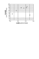
- FIG. 4 shows the half-value width of the peak corresponding to the (012) plane of the solid electrolyte LAGP and the discharge capacity of the all-solid-state battery in the X-ray diffraction pattern obtained by the powder X-ray diffraction measurement of the positive electrode layer of the all-solid-state battery. It is a graph which shows the relationship of.
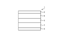
- the all-solid-state battery 1 includes a positive electrode side current collector layer 2, a negative electrode side current collector layer 3, a solid electrolyte layer 5, a positive electrode layer 6, and a negative electrode layer 7.
- FIG. 1 is a cross-sectional view showing a schematic structure of the all-solid-state battery 1 of the embodiment.
- the positive electrode side current collector layer 2 is formed of a conductor and is formed in a film shape.
- the negative electrode side current collector layer 3 is formed of a conductor and is formed in a film shape.
- a metal is exemplified as the conductor.
- the solid electrolyte layer 5 contains the solid electrolyte LAGP.
- the solid electrolyte LAGP is formed from a compound represented by the following chemical formula. Li 1.5 Al 0.5 Ge 1.5 (PO 4 ) 3
- the solid electrolyte layer 5 is formed in a film shape.
- the solid electrolyte layer 5 is arranged between the positive electrode side current collector layer 2 and the negative electrode side current collector layer 3.
- the positive electrode layer 6 contains a positive electrode active material LCPO, a solid electrolyte LAGP, and a conductive auxiliary agent.
- the positive electrode active material LCPO is formed from a compound represented by the following chemical formula. Li 2 CoP 2 O 7
- the positive electrode layer 6 is formed in a film shape.
- the positive electrode layer 6 is arranged between the positive electrode side current collector layer 2 and the solid electrolyte layer 5, is in contact with the positive electrode side current collector layer 2, and is in contact with the solid electrolyte layer 5.
- the negative electrode layer 7 contains a negative electrode active material, a solid electrolyte LAGP, and a conductive auxiliary agent.
- the negative electrode active material include lithium vanadium phosphate Li 3 V 2 (PO 4 ) 3 , lithium titanate Li 4 Ti 5 O 12 , titanium oxide TIO 2 , and niobium pentoxide Nb 2 O 5 .
- the negative electrode layer 7 is formed in a film shape.
- the negative electrode layer 7 is arranged between the negative electrode side current collector layer 3 and the solid electrolyte layer 5, is in contact with the negative electrode side current collector layer 3, and is in contact with the solid electrolyte layer 5.
- FIG. 2 is a graph showing an X-ray diffraction pattern 11 obtained by performing powder X-ray diffraction on the positive electrode layer 6 of the all-solid-state battery 1 of the embodiment.
- the X-ray diffraction pattern 11 shows an approximate continuous function that associates the incident angle 2 ⁇ (deg) with the intensity, and a plurality of peaks are formed.
- the plurality of peaks includes peak 12, peak 13, peak 14, and peak 15.
- the peak 12 corresponds to the (110) plane of the positive electrode active material LCPO.
- the peak 13 corresponds to the surface represented by the following equation of the positive electrode active material LCPO.
- the peak 14 shows the maximum value when the incident angle 2 ⁇ is equal to 15.0 ° ⁇ 0.2 °, and corresponds to the (012) plane of the solid electrolyte LAGP.
- the peak 15 corresponds to the (002) plane of the positive electrode active material LCPO.
- the peak 14 does not overlap any of the plurality of peaks corresponding to the positive electrode active material LCPO.
- the full width at half maximum FWHM of the peak 14 satisfies the following equation. 0.178 ⁇ FWHM ⁇ 0.317
- the full width at half maximum FWHM of the peak 14 is calculated with an intensity corresponding to half of the maximum intensity of the peak 14 based on the pattern obtained by removing the background from the X-ray diffraction pattern 11, and the portion of the peak 14 corresponding to the intensity is calculated. Calculated based on the corresponding spread angle.
- the all-solid-state battery 1 has an improved discharge capacity when the full width at half maximum FWHM of the peak 14 shows such a value.
- the solid-state battery manufacturing method of the embodiment includes preparation of a powder of the positive electrode active material LCPO, preparation of a powder of the solid electrolyte LAGP, preparation of an all-solid-state battery, and powder X-ray diffraction measurement of the positive electrode layer. ..
- the powder of the solid electrolyte LAGP is prepared using the solid phase method. That is, a predetermined amount of lithium carbonate Li 2 CO 3 powder, aluminum oxide Al 2 O 3 powder, germanium GeO 2 powder, and ammonium dihydrogen phosphate NH 4 H 2 PO 4 powder. And are prepared and mixed. The mixture prepared by mixing is calcined at 300 ° C. to 400 ° C. for 3 to 5 hours. The calcined powder prepared by calcining is dissolved by heat treatment at 1200 ° C. to 1400 ° C. for 1 to 2 hours. The melt prepared by the heat treatment is rapidly cooled and vitrified to prepare a powder of the amorphous solid electrolyte LAGP.
- Crystallized solid electrolyte LAGP powder is prepared by firing the amorphous solid electrolyte LAGP powder at, for example, 600 ° C. to 900 ° C.
- the powder of the solid electrolyte LAGP used for producing the all-solid battery is the powder of the amorphous solid electrolyte LAGP, the powder of the crystallized solid electrolyte LAGP, or the amorphous solid electrolyte LAGP. Is a mixture of the powder of LAGP and the powder of the crystallized solid electrolyte LAGP.
- the powder of the solid electrolyte LAGP formed from the compound represented by the chemical formula Li 1.5 Al 0.5 Ge 1.5 (PO 4 ) 3 can be appropriately prepared. ..
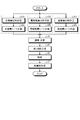
- FIG. 3 is a flowchart showing an outline of manufacturing of an all-solid-state battery.
- a ceramic powder for a positive electrode is prepared by mixing a powder of the positive electrode active material LCPO and a powder of the solid electrolyte LAGP at a predetermined mass ratio (for example, 50:50).
- a binder, a solvent (anhydrous alcohol), and a conductive additive are added to the ceramic powder for a positive electrode and mixed to prepare a slurry-like positive electrode layer material (step s1a).
- the slurry-shaped positive electrode layer material is coated on a PET film by the doctor blade method and formed into a sheet shape.
- the plurality of positive electrode layer green sheets formed in the form of a sheet are laminated and press-bonded to adjust the thickness to a predetermined value.
- the positive electrode layer green sheet laminated and press-bonded is cut into a predetermined size to produce a positive electrode layer sheet (step s2a).
- the powder of the solid electrolyte LAGP is kneaded together with the binder, the dispersant, the plasticizer, and the non-aqueous solvent to prepare a slurry-like electrolyte layer material (step s1b).
- the slurry-like electrolyte layer material is coated on a PET film by the doctor blade method and formed into a sheet shape.
- the plurality of electrolyte layer green sheets formed in the form of a sheet are laminated and press-bonded to adjust to a predetermined thickness.
- the electrolyte layer green sheet whose thickness has been adjusted is cut into a predetermined size to prepare a solid electrolyte layer sheet (step s2b).
- a powder of the negative electrode active material is prepared.
- the negative electrode active material include lithium vanadium phosphate Li 3 V 2 (PO 4 ) 3 , lithium titanate Li 4 Ti 5 O 12 , titanium oxide TIO 2 , and niobium pentoxide Nb 2 O 5 .
- a ceramic powder for a negative electrode is prepared by mixing a powder of a negative electrode active material and a powder of a solid electrolyte LAGP at a predetermined mass ratio (for example, 50:50).
- a binder, a solvent (anhydrous alcohol), and a conductive additive are added to the ceramic powder for the negative electrode and mixed to prepare a slurry-like negative electrode layer material (step s1c).
- the slurry-shaped negative electrode layer material is coated on a PET film by the doctor blade method and formed into a sheet shape.
- the plurality of negative electrode layer green sheets formed in the form of a sheet are laminated and press-bonded to adjust to a predetermined thickness.
- the negative electrode layer green sheet whose thickness has been adjusted is cut into a predetermined size to produce a negative electrode layer sheet (step s2c).
- the solid electrolyte layer sheet, the positive electrode layer sheet, and the negative electrode layer sheet are laminated and crimped so that the solid electrolyte layer sheet is sandwiched between the positive electrode layer sheet and the negative electrode layer sheet.
- the laminate produced by crimping is heat treated at a predetermined temperature so as to be degreased (step s4).
- the binder contained in the solid electrolyte layer sheet, the positive electrode layer sheet, and the negative electrode layer sheet is thermally decomposed by this heat treatment.
- the degreased laminated body is fired at a predetermined firing temperature to produce a laminated electrode body which is a sintered body (step s6). Further, the solid electrolyte LAGP contained in the solid electrolyte layer sheet, the positive electrode layer sheet, and the negative electrode layer sheet is sintered by this heat treatment.
- the all-solid-state battery 1 is manufactured by sputtering or vapor-depositing both sides of the laminated electrode body and coating it with a metal foil (step s7). At this time, the metal foil covering the surface of the laminated electrode body on the side of the positive electrode layer sheet corresponds to the positive electrode side current collector layer 2.
- the metal foil that covers the surface of the laminated electrode body on the side of the negative electrode layer sheet corresponds to the negative electrode side current collector layer 3.
- the portion formed from the solid electrolyte layer sheet corresponds to the solid electrolyte layer 5.
- the portion formed from the positive electrode layer sheet corresponds to the positive electrode layer 6.
- the portion formed from the negative electrode layer sheet corresponds to the negative electrode layer 7.
- the laminated body is produced by laminating the solid electrolyte layer sheet, the positive electrode layer sheet, and the negative electrode layer sheet, it may be produced by another method different from the laminating of the sheets.
- a positive electrode layer printing paste and a negative electrode layer printing paste are prepared.
- the positive electrode layer printing paste is prepared by mixing a positive electrode ceramic powder, a conductive auxiliary agent, a binder, a dispersant, a plasticizer, and a non-aqueous solvent.
- the negative electrode layer printing paste is prepared by mixing a ceramic powder for a negative electrode, a conductive auxiliary agent, a binder, a dispersant, a plasticizer, and a non-aqueous solvent.
- the positive electrode layer printing paste is applied to one surface of the solid electrolyte layer sheet by screen printing.
- the negative electrode layer printing paste is applied to the other surface of the solid electrolyte layer sheet by screen printing.
- a laminate is produced by coating the solid electrolyte layer sheet with the positive electrode layer printing paste and the negative electrode layer printing paste. By executing the processes of steps s4 to s7, such a laminate is produced in the all-solid-state battery 1 in the same manner as the above-mentioned laminate.
- the powder X-ray diffraction measurement of the positive electrode layer is performed on the positive electrode layer 6 of the all-solid-state battery 1 manufactured by manufacturing the all-solid-state battery.
- an X-ray diffraction pattern is acquired, and half of the peak corresponding to the (012) plane of the solid electrolyte LAGP in the X-ray diffraction pattern. It is determined whether the price range FWHM satisfies the following conditions.
- the all-solid-state battery measured by powder X-ray diffraction is determined to be a non-defective product when the half-value width FWHM satisfies the condition, and is determined to be a defective product when the half-value width FWHM does not satisfy the condition.
- another all-solid-state battery is manufactured under the same conditions as those used when the all-solid-state battery judged to be a non-defective product is manufactured.
- the all-solid-state battery manufacturing method by manufacturing the all-solid-state battery in this way, the all-solid-state battery can be appropriately manufactured so that the half-value width FWHM satisfies the condition.
- a plurality of all-solid-state battery samples have been produced based on the solid-state battery manufacturing method described above.
- the plurality of all-solid-state battery samples include the all-solid-state battery of Example 1, the all-solid-state battery of Example 2, the all-solid-state battery of Comparative Example 1, and the all-solid-state battery of Comparative Example 2.
- Powder of the positive active material LCPO used for the all-solid-state battery of Example 1 ammonium dihydrogen phosphate NH 4 H 2 PO 4 and lithium nitrate LiNO 3 and cobalt nitrate Co (NO 3) 2 ⁇ 6H 2 O and citric
- the acid and pure water are formed from LCPO, which is a positive electrode active material synthesized by a solid-state reaction.
- the synthesized positive electrode active material LCPO is pulverized with a ball mill to a particle size of 0.5 ⁇ m to prepare a powder of the positive electrode active material LCPO used for producing the all-solid-state battery of Example 1.
- the powder of the solid electrolyte LAGP used for producing the all-solid-state battery of Example 1 is produced by using the solid-phase method. That is, the powders of lithium carbonate Li 2 CO 3 , aluminum oxide Al 2 O 3 , germanium dioxide GeO 2, and ammonium dihydrogen phosphate NH 4 H 2 PO 4 are mixed in a magnetic dairy pot and then further mixed in a ball mill. There is. The mixture prepared by mixing is placed in an alumina crucible and heated at 300 ° C. for 5 hours to be calcined. The calcined powder prepared by calcining is heat-treated at 1300 ° C. for 2 hours and then rapidly cooled. The powder vitrified by quenching is pulverized by a ball mill to a particle size of 1.0 ⁇ m to prepare a powder of the solid electrolyte LAGP used for producing the all-solid-state battery of Example 1.
- a positive electrode layer printing paste, a negative electrode layer printing paste, and a solid electrolyte layer sheet are used.
- the conductive aid is formed from carbon nanotubes (eg, VGCF®).
- a paste for printing a positive electrode layer is produced by kneading a binder, a dispersant, a plasticizer, and a non-aqueous solvent in a predetermined ratio with the mixture prepared by mixing.
- a powder of niobium pentoxide Nb 2 O 5 having a particle size of 1.0 ⁇ m is used as the negative electrode active material.
- the conductive aid is formed from carbon nanotubes (eg, VGCF®).
- a paste for printing a negative electrode layer is produced by kneading a binder, a dispersant, a plasticizer, and a non-aqueous solvent in a predetermined ratio with the mixture prepared by mixing.
- the solid electrolyte layer sheet is prepared from a slurry-like electrolyte layer material prepared by kneading a powder of the solid electrolyte LAGP, a binder, a dispersant, a plasticizer, and a non-aqueous solvent at a predetermined ratio. ing.
- the solid electrolyte LAGP the same solid electrolyte LAGP used for producing the paste for printing the positive electrode layer is used.
- a solid electrolyte layer sheet having a thickness of 200 ⁇ m is produced by laminating and press-pressing a plurality of electrolyte layer green sheets prepared by the doctor blade method from a slurry-like electrolyte layer material.
- the positive electrode layer printing paste is applied to one surface of the solid electrolyte layer sheet by screen printing.
- the negative electrode layer printing paste is applied to the other surface of the solid electrolyte layer sheet by screen printing.
- a laminate is produced by coating the solid electrolyte layer sheet with the positive electrode layer printing paste and the negative electrode layer printing paste. The laminate is heated at 50 ° C./hour using Air flow so as to be degreased, heat-treated so as to be held at 500 ° C. for 5 hours, and cooled by natural cooling. After being degreased, the laminate is heated at 50 ° C./hour using a nitrogen flow so as to be fired, heat-treated so as to be maintained at 587 ° C. for 5 hours, and cooled by natural cooling.
- a laminated electrode body is produced by firing the laminated body.
- the all-solid-state battery of Example 1 is manufactured by sputtering a thin film of gold Au on both sides of the laminated electrode body.
- the thin film covering the surface of the laminated electrode body on the side of the positive electrode layer printing paste corresponds to the positive electrode side current collector layer 2.
- the thin film that covers the surface of the laminated electrode body on the side of the negative electrode layer printing paste corresponds to the negative electrode side current collector layer 3.
- the portion formed from the solid electrolyte layer sheet corresponds to the solid electrolyte layer 5.
- the portion formed from the positive electrode layer printing paste corresponds to the positive electrode layer 6.
- the portion formed from the negative electrode layer printing paste corresponds to the negative electrode layer 7.
- the all-solid-state battery of Example 2 is manufactured in the same manner as the all-solid-state battery of Example 1 except that the firing temperature at which the degreased laminate is fired is 600 ° C.
- the all-solid-state battery of Example 3 is manufactured in the same manner as the all-solid-state battery of Example 1 except that the firing temperature at which the degreased laminate is fired is 612 ° C.
- the all-solid-state battery of Example 4 is manufactured in the same manner as the all-solid-state battery of Example 1 except that the firing temperature at which the degreased laminate is fired is 625 ° C.
- the all-solid-state battery of Example 5 is manufactured in the same manner as the all-solid-state battery of Example 1 except that the firing temperature at which the degreased laminate is fired is 637 ° C.
- the all-solid-state battery of Comparative Example 1 is manufactured in the same manner as the all-solid-state battery of Example 1 except that the firing temperature at which the degreased laminate is fired is 575 ° C.
- the all-solid-state battery of Comparative Example 2 is manufactured in the same manner as the all-solid-state battery of Example 1 except that the firing temperature at which the degreased laminate is fired is 650 ° C.
- Each of the plurality of all-solid-state battery samples has undergone an XRD measurement test and a charge / discharge characteristic evaluation test.
- An XRD measurement test is performed on a plurality of all-solid-state battery samples, and the results of the XRD measurement test are analyzed to obtain a plurality of X-ray diffraction patterns corresponding to the plurality of all-solid-state battery samples.
- each X-ray diffraction pattern of the plurality of X-ray diffraction patterns shows an approximate continuous function that associates the incident angle 2 ⁇ with the intensity, and a plurality of peaks are formed.
- a plurality of full width at half maximum FWHM corresponding to a plurality of all-solid-state battery samples are further calculated.
- the half-width FWHM corresponding to an all-solid-state battery sample among a plurality of half-width FWHMs is a solid electrolyte LAGP of the X-ray diffraction pattern corresponding to the all-solid-state battery sample among a plurality of X-ray diffraction patterns.
- the half width FWHM of the peak corresponding to the plane is shown.
- the intensity corresponding to half of the maximum intensity of the peak is calculated based on the pattern obtained by removing the background from the X-ray diffraction pattern, and the spread angle corresponding to the portion of the peak corresponding to the intensity is calculated. It is calculated based on.
- the full width at half maximum FWHM corresponding to the all-solid-state battery of Example 1 shows 0.317 °.
- the full width at half maximum FWHM corresponding to the all-solid-state battery of Example 2 shows 0.310 °.
- the full width at half maximum FWHM corresponding to the all-solid-state battery of Example 3 shows 0.274 °.
- the full width at half maximum FWHM corresponding to the all-solid-state battery of Example 4 shows 0.241 °.
- the full width at half maximum FWHM corresponding to the all-solid-state battery of Example 5 shows 0.178 °.
- the full width at half maximum FWHM corresponding to the all-solid-state battery of Comparative Example 1 shows 0.352 °.
- the full width at half maximum FWHM corresponding to the all-solid-state battery of Comparative Example 2 is 0.127 °.
- the discharge capacity corresponding to the all-solid-state battery of Example 1 is 84.5 mAh / g.
- the discharge capacity corresponding to the all-solid-state battery of Example 2 is 78.0 mAh / g.
- the discharge capacity corresponding to the all-solid-state battery of Example 3 is 74.7 mAh / g.
- the discharge capacity corresponding to the all-solid-state battery of Example 4 is 77.7 mAh / g.
- the discharge capacity corresponding to the all-solid-state battery of Example 5 is 59.5 mAh / g.
- the discharge capacity corresponding to the all-solid-state battery of Comparative Example 1 is 30.9 mAh / g.
- the discharge capacity corresponding to the all-solid-state battery of Comparative Example 2 is 38.9 mAh / g.
- Table 1 shows the half-value width of the peak corresponding to the (012) plane of the solid electrolyte LAGP and the discharge capacity of the all-solid-state battery in the X-ray diffraction pattern as a result of the powder X-ray diffraction measurement of the positive electrode layer of the all-solid-state battery. Shows the relationship.
- FIG. 4 shows the half-value width of the peak corresponding to the (012) plane of the solid electrolyte LAGP and the discharge capacity of the all-solid-state battery in the X-ray diffraction pattern obtained by the powder X-ray diffraction measurement of the positive electrode layer of the all-solid-state battery. It is a graph which shows the relationship of.
- the half width FWHM of a peak in the X-ray diffraction pattern is related to the size of the crystallite corresponding to the peak.
- the fact that the full width at half maximum FWHM is smaller than 0.178 indicates that the crystallinity of the solid electrolyte LAGP in the positive electrode layer 6 is improved, and that the ionic conduction of the positive electrode layer 6 is increased. ..
- the fact that the full width at half maximum FWHM is smaller than 0.178 further indicates that the reactivity between the positive electrode active material LCPO and the solid electrolyte LAGP is enhanced in the positive electrode layer 6.
- the half-value width FWHM is smaller than 0.178, the inside of the positive electrode layer 6 is in a state where another crystal phase that becomes a resistance component of the positive electrode layer 6 is generated, and the all-solid-state battery including the positive electrode layer 6 In No. 1, it is considered that the charge / discharge characteristics are deteriorated.
- the half width FWHM is larger than 0.317, it indicates that the glass of the solid electrolyte LAGP is not sufficiently crystallized and the ionic conductivity is low. Therefore, it is considered that the all-solid-state battery 1 provided with the positive electrode layer 6 having a half-value width FWHM larger than 0.317 has deteriorated charge / discharge characteristics.
- the all-solid-state battery 1 of the embodiment includes a positive electrode layer 6, a negative electrode layer 7, and a solid electrolyte layer 5 sandwiched between the positive electrode layer 6 and the negative electrode layer 7.
- the positive electrode layer 6 is formed of a positive electrode active material LCPO formed from a compound represented by the chemical formula Li 2 CoP 2 O 7 and a compound represented by the chemical formula Li 1 + x Al x Ge 2-x (PO 4 ) 3. Contains the solid electrolyte LAGP.
- the number x satisfies the following equation.
- the full width at half maximum FWHM of the peak 14 corresponding to the (012) plane of the solid electrolyte LAGP in the X-ray diffraction pattern 11 obtained by performing the powder X-ray diffraction measurement using CuK ⁇ for the positive electrode layer 6 is as follows. Meet. 0.178 ⁇ FWHM ⁇ 0.317 At this time, the all-solid-state battery 1 prevents the crystal phase, which is the resistance component of the positive electrode layer 6, from being generated in the positive electrode layer 6 by the reaction between the positive electrode active material LCPO and the solid electrolyte LAGP, and improves the discharge capacity. Can be done.
- the positive electrode layer 6 of the all-solid-state battery 1 of the embodiment may further contain a conductive auxiliary agent that reduces the electrical resistance of the positive electrode layer 6.
- a conductive auxiliary agent that reduces the electrical resistance of the positive electrode layer 6.
- the positive electrode layer 6 of the all-solid-state battery 1 described above contains the conductive auxiliary agent, it does not have to contain the conductive auxiliary agent.
- the negative electrode layer 7 of the all-solid-state battery 1 described above contains the conductive auxiliary agent, it does not have to contain the conductive auxiliary agent.
- the half-value width FWHM of the peak 14 is included in a specific range regardless of whether the positive electrode layer 6 does not contain the conductive auxiliary agent or the negative electrode layer 7 does not contain the conductive auxiliary agent. The discharge capacity can be improved.
- the solid electrolyte LAGP of the all-solid-state battery 1 of the embodiment may be formed from a compound represented by the chemical formula Li 1.5 Al 0.5 Ge 1.5 (PO 4 ) 3.
- the positive electrode layer 6 described above contains the solid electrolyte LAGP represented by the chemical formula Li 1.5 Al 0.5 Ge 1.5 (PO 4 ) 3 , but the chemical formula Li 1 + x Al x Ge 2-
- the solid electrolyte LAGP represented by x (PO 4 ) 3 (0 ⁇ x ⁇ 1) may be contained.
- the all-solid-state battery 1 has a full width at half maximum FWHM of peak 14 even when it contains the solid electrolyte LAGP formed from the chemical formula Li 1 + x Al x Ge 2-x (PO 4 ) 3 (0 ⁇ x ⁇ 1). By being included in a specific range, the discharge capacity can be improved.
- the positive electrode of the embodiment is used for the positive electrode layer 6 in an all-solid-state battery including a laminated electrode body in which a solid electrolyte layer 5 is sandwiched between the positive electrode layer 6 and the negative electrode layer 7.
- the positive electrode is a positive electrode active material LCPO formed from a compound represented by the chemical formula Li 2 CoP 2 O 7 , and a solid electrolyte formed from a compound represented by the chemical formula Li 1 + x Al x Ge 2-x (PO 4 ) 3.
- LAGP LAGP.
- the number x satisfies the following equation.
- the all-solid-state battery manufacturing method of the embodiment is a method of manufacturing an all-solid-state battery including a laminated electrode body in which a solid electrolyte layer 5 is sandwiched between a positive electrode layer 6 and a negative electrode layer 7.
- the peak corresponding to the (012) plane of the fixed electrolyte LAGP in the X-ray diffraction pattern obtained by performing the powder X-ray diffraction measurement using CuK ⁇ on the positive electrode layer 6 It is provided to calculate the half width FWHM of.
- the all-solid-state battery manufacturing method of the embodiment further comprises manufacturing an all-solid-state battery using a positive electrode layer 6 prepared so that the full width at half maximum FWHM satisfies the following equation. 0.178 ⁇ FWHM ⁇ 0.317 At this time, the all-solid-state battery manufactured by the all-solid-state battery manufacturing method can improve the discharge capacity.
Landscapes
- Chemical & Material Sciences (AREA)
- General Chemical & Material Sciences (AREA)
- Chemical Kinetics & Catalysis (AREA)
- Electrochemistry (AREA)
- Manufacturing & Machinery (AREA)
- Engineering & Computer Science (AREA)
- Inorganic Chemistry (AREA)
- Organic Chemistry (AREA)
- Physics & Mathematics (AREA)
- Condensed Matter Physics & Semiconductors (AREA)
- General Physics & Mathematics (AREA)
- Secondary Cells (AREA)
- Battery Electrode And Active Subsutance (AREA)
Abstract
全固体電池1は、正極層(6)と、負極層(7)と、正極層(6)と負極層(7)との間に狭持される固体電解質層(5)とを備えている。正極層(6)は、化学式Li2CoP2O7で表される化合物LCPOから形成される正極活物質と、化学式Li1+xAlxGe2-x(PO4)3で表される化合物LAGPから形成される固体電解質とを含んでいる。ここで、数xは、次式を満たしている。 0<x<1 CuKαを利用した粉末X線回折測定を正極層(6)について実行することにより取得されるX線回折パターンのうちの化合物LAGPの(012)面に対応するピークの半値幅FWHMは、次式を満たしている。 0.178≦FWHM≦0.317
Description
本開示の技術は、全固体電池、正極および全固体電池製造方法に関する。
固体の電解質を用いた全固体電池が知られている(特許文献1)。全固体電池は、リチウムイオン電池に利用される可燃性の有機電解液を備えていないことにより、有機電解液により発生する不具合と同様の他の不具合の発生を低減することができる。
ピロリン酸型の正極材料Li2CoP2O7は、平均電位vsLi/Li+5Vで200mAh/g程度の性能を有する材料であり、全固体電池のエネルギー密度向上に有効な材料である。正極材料Li2CoP2O7は、酸化物系固体電池へ用いる場合、焼成時に固体電解質と反応して充放電に寄与しない異相が生成するという問題がある。正極材料Li2CoP2O7が用いられる酸化物系固体電池は、このような異相が生成することにより、放電容量が低下することがある。
開示の技術は、かかる点に鑑みてなされたものであって、放電容量を向上させる全固体電池、正極および全固体電池製造方法を提供することを目的とする。
本開示の一態様による全固体電池は、正極層と、負極層と、正極層と負極層との間に狭持される固体電解質層とを備えている。前記正極層は、化学式Li2CoP2O7で表される化合物LCPOから形成される正極活物質と、化学式Li1+xAlxGe2-x(PO4)3で表される化合物LAGPから形成される固体電解質とを含んでいる。数xは、次式を満たしている。
0<x<1
CuKαを利用した粉末X線回折測定を前記正極層について実行することにより取得されるX線回折パターンのうちの前記化合物LAGPの(012)面に対応するピークの半値幅FWHMは、次式を満たしている。
0.178≦FWHM≦0.317
0<x<1
CuKαを利用した粉末X線回折測定を前記正極層について実行することにより取得されるX線回折パターンのうちの前記化合物LAGPの(012)面に対応するピークの半値幅FWHMは、次式を満たしている。
0.178≦FWHM≦0.317
開示の全固体電池、正極および全固体電池製造方法は、放電容量を向上させることができる。
以下に、本願が開示する実施形態にかかる全固体電池、正極および全固体電池製造方法について、図面を参照して説明する。なお、以下の記載により本開示の技術が限定されるものではない。また、以下の記載においては、同一の構成要素に同一の符号を付与し、重複する説明を省略する。
[全固体電池]
全固体電池1は、図1に示されているように、正極側集電体層2と負極側集電体層3と固体電解質層5と正極層6と負極層7とを備えている。図1は、実施形態の全固体電池1の概略構造を示す断面図である。正極側集電体層2は、導体から形成され、膜状に形成されている。負極側集電体層3は、導体から形成され、膜状に形成されている。導体としては、金属が例示される。
全固体電池1は、図1に示されているように、正極側集電体層2と負極側集電体層3と固体電解質層5と正極層6と負極層7とを備えている。図1は、実施形態の全固体電池1の概略構造を示す断面図である。正極側集電体層2は、導体から形成され、膜状に形成されている。負極側集電体層3は、導体から形成され、膜状に形成されている。導体としては、金属が例示される。
固体電解質層5は、固体電解質LAGPを含んでいる。固体電解質LAGPは、次化学式で表される化合物から形成されている。
Li1.5Al0.5Ge1.5(PO4)3
固体電解質層5は、膜状に形成されている。固体電解質層5は、正極側集電体層2と負極側集電体層3との間に配置されている。
Li1.5Al0.5Ge1.5(PO4)3
固体電解質層5は、膜状に形成されている。固体電解質層5は、正極側集電体層2と負極側集電体層3との間に配置されている。
正極層6は、正極活物質LCPOと固体電解質LAGPと導電助剤とを含んでいる。正極活物質LCPOは、次化学式で表される化合物から形成されている。
Li2CoP2O7
正極層6は、膜状に形成されている。正極層6は、正極側集電体層2と固体電解質層5との間に配置され、正極側集電体層2に接触し、固体電解質層5に接触している。
Li2CoP2O7
正極層6は、膜状に形成されている。正極層6は、正極側集電体層2と固体電解質層5との間に配置され、正極側集電体層2に接触し、固体電解質層5に接触している。
負極層7は、負極活物質と固体電解質LAGPと導電助剤とを含んでいる。負極活物質としては、リン酸バナジウムリチウムLi3V2(PO4)3、チタン酸リチウムLi4Ti5O12、酸化チタンTiO2、五酸化ニオブNb2O5が例示される。負極層7は、膜状に形成されている。負極層7は、負極側集電体層3と固体電解質層5との間に配置され、負極側集電体層3に接触し、固体電解質層5に接触している。
後述する粉末X線回折測定が全固体電池1の正極層6について実施されることにより、図2に示されているように、X線回折パターン11が取得される。図2は、実施形態の全固体電池1の正極層6について粉末X線回折を実行することにより得られたX線回折パターン11を示すグラフである。X線回折パターン11は、入射角2θ(deg)を強度に対応付ける近似的な連続関数を示し、複数のピークが形成されている。たとえば、複数のピークは、ピーク12とピーク13とピーク14とピーク15とを含んでいる。ピーク12は、正極活物質LCPOの(110)面に対応している。ピーク13は、正極活物質LCPOの次式により表現される面に対応している。

ピーク14は、入射角2θが15.0°±0.2°に等しいときに最大値を示し、固体電解質LAGPの(012)面に対応している。ピーク15は、正極活物質LCPOの(002)面に対応している。ピーク14は、正極活物質LCPOに対応する複数のピークのいずれにも重なっていない。
ピーク14の半値幅FWHMは、次式を満たしている。
0.178≦FWHM≦0.317
ピーク14の半値幅FWHMは、X線回折パターン11からバックグラウンドを除去したパターンに基づいてピーク14の最大強度の半分に相当する強度が算出され、ピーク14のうちのその強度に相当する部分に対応する広がり角度に基づいて算出される。全固体電池1は、ピーク14の半値幅FWHMがこのような値を示すときに、放電容量が向上する。
0.178≦FWHM≦0.317
ピーク14の半値幅FWHMは、X線回折パターン11からバックグラウンドを除去したパターンに基づいてピーク14の最大強度の半分に相当する強度が算出され、ピーク14のうちのその強度に相当する部分に対応する広がり角度に基づいて算出される。全固体電池1は、ピーク14の半値幅FWHMがこのような値を示すときに、放電容量が向上する。
[固体電池製造方法]
実施形態の固体電池製造方法は、正極活物質LCPOの粉体の調製と、固体電解質LAGPの粉体の調製と、全固体電池の作製と、正極層の粉末X線回折測定とを備えている。
実施形態の固体電池製造方法は、正極活物質LCPOの粉体の調製と、固体電解質LAGPの粉体の調製と、全固体電池の作製と、正極層の粉末X線回折測定とを備えている。
[正極活物質LCPOの粉体の調製]
正極活物質LCPOの粉体の調製では、予め定められた量のリン酸二水素アンモニウムNH4H2PO4と硝酸リチウムLiNO3と硝酸コバルトCo(NO3)2・6H2Oとクエン酸と純水とが、準備され、混合される。混合により調製された混合物は、混合物中の水が蒸発するように加熱される。加熱された混合物は、600~700℃で2時間~6時間加熱されることにより、本焼成される。本焼成により調製された焼成品が粉砕されることにより、正極活物質LCPOの粉体が調製される。このように手順によれば、化学式Li2CoP2O7で表される化合物から形成される正極活物質LCPOの粉体が適切に調製されることができる。
正極活物質LCPOの粉体の調製では、予め定められた量のリン酸二水素アンモニウムNH4H2PO4と硝酸リチウムLiNO3と硝酸コバルトCo(NO3)2・6H2Oとクエン酸と純水とが、準備され、混合される。混合により調製された混合物は、混合物中の水が蒸発するように加熱される。加熱された混合物は、600~700℃で2時間~6時間加熱されることにより、本焼成される。本焼成により調製された焼成品が粉砕されることにより、正極活物質LCPOの粉体が調製される。このように手順によれば、化学式Li2CoP2O7で表される化合物から形成される正極活物質LCPOの粉体が適切に調製されることができる。
[固体電解質LAGPの粉体の調製]
固体電解質LAGPの粉体は、固相法を用いて調製される。すなわち、予め定められた量の炭酸リチウムLi2CO3の粉体と酸化アルミニウムAl2O3の粉体と二酸化ゲルマニウムGeO2の粉体とリン酸二水素アンモニウムNH4H2PO4の粉体とが、準備され、混合される。混合により調製された混合物は、300℃~400℃で3時間~5時間仮焼成される。仮焼成により調製された仮焼き粉体は、1200℃~1400℃で1時間~2時間熱処理されることにより、溶解される。熱処理により調製された溶解物が急冷されてガラス化されることにより、非晶質の固体電解質LAGPの粉体が調製される。非晶質の固体電解質LAGPの粉体が例えば600℃~900℃で焼成されることにより、結晶化された固体電解質LAGPの粉体が調製される。全固体電池の作製に利用される固体電解質LAGPの粉体は、非晶質の固体電解質LAGPの粉体、または、結晶化された固体電解質LAGPの粉体、または、非晶質の固体電解質LAGPの粉体と結晶化された固体電解質LAGPの粉体との混合物である。このように手順によれば、化学式Li1.5Al0.5Ge1.5(PO4)3で表される化合物から形成される固体電解質LAGPの粉体が適切に調製されることができる。
固体電解質LAGPの粉体は、固相法を用いて調製される。すなわち、予め定められた量の炭酸リチウムLi2CO3の粉体と酸化アルミニウムAl2O3の粉体と二酸化ゲルマニウムGeO2の粉体とリン酸二水素アンモニウムNH4H2PO4の粉体とが、準備され、混合される。混合により調製された混合物は、300℃~400℃で3時間~5時間仮焼成される。仮焼成により調製された仮焼き粉体は、1200℃~1400℃で1時間~2時間熱処理されることにより、溶解される。熱処理により調製された溶解物が急冷されてガラス化されることにより、非晶質の固体電解質LAGPの粉体が調製される。非晶質の固体電解質LAGPの粉体が例えば600℃~900℃で焼成されることにより、結晶化された固体電解質LAGPの粉体が調製される。全固体電池の作製に利用される固体電解質LAGPの粉体は、非晶質の固体電解質LAGPの粉体、または、結晶化された固体電解質LAGPの粉体、または、非晶質の固体電解質LAGPの粉体と結晶化された固体電解質LAGPの粉体との混合物である。このように手順によれば、化学式Li1.5Al0.5Ge1.5(PO4)3で表される化合物から形成される固体電解質LAGPの粉体が適切に調製されることができる。
[全固体電池の作製]
図3は、全固体電池の作製の概略を示すフローチャートである。正極活物質LCPOの粉体と固体電解質LAGPの粉体とが、予め定められた質量比(たとえば、50:50)で混合されることにより、正極用セラミック粉体が調製される。正極用セラミック粉体に、バインダーと溶媒(無水アルコール)と導電助剤とが添加され、混合されることにより、スラリー状の正極層材料が調製される(ステップs1a)。スラリー状の正極層材料は、ドクターブレード法により、PETフィルム上に塗工され、シート状に成形される。シート状に形成された複数枚の正極層グリーンシートは、積層され、プレス圧着されることにより、予め定められた厚さに調整される。積層・プレス圧着された正極層グリーンシートが、予め定められたサイズに切断されことにより、正極層シートが作製される(ステップs2a)。
図3は、全固体電池の作製の概略を示すフローチャートである。正極活物質LCPOの粉体と固体電解質LAGPの粉体とが、予め定められた質量比(たとえば、50:50)で混合されることにより、正極用セラミック粉体が調製される。正極用セラミック粉体に、バインダーと溶媒(無水アルコール)と導電助剤とが添加され、混合されることにより、スラリー状の正極層材料が調製される(ステップs1a)。スラリー状の正極層材料は、ドクターブレード法により、PETフィルム上に塗工され、シート状に成形される。シート状に形成された複数枚の正極層グリーンシートは、積層され、プレス圧着されることにより、予め定められた厚さに調整される。積層・プレス圧着された正極層グリーンシートが、予め定められたサイズに切断されことにより、正極層シートが作製される(ステップs2a)。
さらに、固体電解質LAGPの粉体が、バインダーと分散剤と可塑剤と非水系溶剤とともに混練されることにより、スラリー状の電解質層材料が調製される(ステップs1b)。スラリー状の電解質層材料は、ドクターブレード法により、PETフィルム上に塗工され、シート状に成形される。シート状に形成された複数枚の電解質層グリーンシートは、積層され、プレス圧着されることにより、予め定められた厚さに調整される。厚さが調製された電解質層グリーンシートが、予め定められたサイズに切断されことにより、固体電解質層シートが作製される(ステップs2b)。
さらに、負極活物質の粉体が準備される。負極活物質としては、リン酸バナジウムリチウムLi3V2(PO4)3、チタン酸リチウムLi4Ti5O12、酸化チタンTiO2、五酸化ニオブNb2O5が例示される。負極活物質の粉体と固体電解質LAGPの粉体とが、予め定められた質量比(たとえば、50:50)で混合されることにより、負極用セラミック粉体が調製される。負極用セラミック粉体に、バインダーと溶媒(無水アルコール)と導電助剤とが添加され、混合されることにより、スラリー状の負極層材料が調製される(ステップs1c)。スラリー状の負極層材料は、ドクターブレード法により、PETフィルム上に塗工され、シート状に成形される。シート状に形成された複数枚の負極層グリーンシートは、積層され、プレス圧着されることにより、予め定められた厚さに調整される。厚さが調製された負極層グリーンシートが、予め定められたサイズに切断されことにより、負極層シートが作製される(ステップs2c)。
固体電解質層シートと正極層シートと負極層シートとは、固体電解質層シートが正極層シートと負極層シートとで狭持されるように、積層され、圧着される。圧着により作製された積層体は、脱脂されるように、予め定められた温度で熱処理される(ステップs4)。固体電解質層シートと正極層シートと負極層シートとに含まれるバインダーは、この熱処理により、熱分解される。
脱脂された積層体が、予め定められた焼成温度で焼成されることにより、焼結体である積層電極体が作製される(ステップs6)。さらに、固体電解質層シートと正極層シートと負極層シートとに含まれる固体電解質LAGPは、この熱処理により、焼結する。積層電極体の両面がスパッタリングまたは蒸着され、金属箔に被覆されることにより、全固体電池1が作製される(ステップs7)。このとき、積層電極体のうちの正極層シートの側の表面を被覆する金属箔は、正極側集電体層2に対応している。積層電極体のうちの負極層シートの側の表面を被覆する金属箔は、負極側集電体層3に対応している。固体電解質層シートから形成された部分は、固体電解質層5に対応している。正極層シートから形成された部分は、正極層6に対応している。負極層シートから形成された部分は、負極層7に対応している。
なお、積層体は、固体電解質層シートと正極層シートと負極層シートとが積層されることにより、作製されているが、シートの積層と異なる他の方法により作製されてもよい。たとえば、正極層印刷用ペーストと負極層印刷用ペーストとが調製される。正極層印刷用ペーストは、正極用セラミック粉体と導電助剤とバインダーと分散剤と可塑剤と非水系溶剤とが混合されることにより調製される。負極層印刷用ペーストは、負極用セラミック粉体と導電助剤とバインダーと分散剤と可塑剤と非水系溶剤とが混合されることにより調製される。正極層印刷用ペーストは、スクリーン印刷により、固体電解質層シートの一方の面に塗工される。負極層印刷用ペーストは、スクリーン印刷により、固体電解質層シートの他方の面に塗工される。固体電解質層シートに正極層印刷用ペーストと負極層印刷用ペーストとが塗工されることにより、積層体が作製される。このような積層体は、ステップs4~s7の処理が実行されることにより、既述の積層体と同様に、全固体電池1に作製される。
[正極層の粉末X線回折測定]
正極層の粉末X線回折測定では、全固体電池の作製で作製された全固体電池1の正極層6について実施される。全固体電池1の正極層6について粉末X線回折測定が実施されることにより、X線回折パターンが取得され、X線回折パターンのうちの固体電解質LAGPの(012)面に対応するピークの半値幅FWHMが次条件を満たすかどうかが判定される。
0.178≦FWHM≦0.317
粉末X線回折測定された全固体電池は、半値幅FWHMが条件を満たすときに、良品と判定され、半値幅FWHMが条件を満たさないときに、不良品と判定される。
正極層の粉末X線回折測定では、全固体電池の作製で作製された全固体電池1の正極層6について実施される。全固体電池1の正極層6について粉末X線回折測定が実施されることにより、X線回折パターンが取得され、X線回折パターンのうちの固体電解質LAGPの(012)面に対応するピークの半値幅FWHMが次条件を満たすかどうかが判定される。
0.178≦FWHM≦0.317
粉末X線回折測定された全固体電池は、半値幅FWHMが条件を満たすときに、良品と判定され、半値幅FWHMが条件を満たさないときに、不良品と判定される。
実施形態の固体電池製造方法では、良品と判定された全固体電池が作製されたときに用いられた条件と同じ条件で、他の全固体電池を作製する。固体電池製造方法は、このように全固体電池が作製されることにより、半値幅FWHMが条件を満たすように、全固体電池を適切に作製することができる。
既述の固体電池製造方法に基づいて複数の全固体電池試料が作製されている。その複数の全固体電池試料は、実施例1の全固体電池と、実施例2の全固体電池と、比較例1の全固体電池と、比較例2の全固体電池とを含んでいる。
実施例1の全固体電池に用いられる正極活物質LCPOの粉体は、リン酸二水素アンモニウムNH4H2PO4と硝酸リチウムLiNO3と硝酸コバルトCo(NO3)2・6H2Oとクエン酸と純水が固相反応で合成された正極活物質LCPOから形成されている。その合成された正極活物質LCPOが0.5μmの粒径までボールミルで粉砕されることにより、実施例1の全固体電池の作製に用いられる正極活物質LCPOの粉体が調製されている。
実施例1の全固体電池の作製に用いられる固体電解質LAGPの粉体は、固相法を用いて作製されている。すなわち、炭酸リチウムLi2CO3と酸化アルミニウムAl2O3と二酸化ゲルマニウムGeO2とリン酸二水素アンモニウムNH4H2PO4の粉体が磁性乳鉢で混合された後に、ボールミルでさらに混合されている。混合により調製された混合物は、アルミナルツボに入れられ、300℃で5時間加熱されることにより、仮焼成されている。仮焼成により調製された仮焼き粉体は、1300℃で2時間熱処理された後に、急冷されている。急冷によりガラス化された粉体が1.0μmの粒径までボールミルで粉砕されることにより、実施例1の全固体電池の作製に用いられる固体電解質LAGPの粉体が調製されている。
実施例1の全固体電池の作製では、正極層印刷用ペーストと負極層印刷用ペーストと固体電解質層シートとが用いられている。正極層印刷用ペーストは、正極活物質LCPOと固体電解質LAGPと導電助剤とが、正極活物質LCPO:固体電解質LAGP:VGCF=3.88:5.82:0.3の重量比で混合された混合物により調製されている。導電助剤は、カーボンナノチューブ(たとえば、VGCF(登録商標))から形成されている。混合により調製された混合物に、バインダーと分散剤と可塑剤と非水系溶剤とが予め定められた比率で混練されることにより、正極層印刷用ペーストが作製されている。
負極層印刷用ペーストは、負極活物質と固体電解質LAGPと導電助剤とが、負極活物質:固体電解質LAGP:VGCF=3.88:5.82:0.3の重量比で混合された混合物により調製されている。負極活物質としては、粒径が1.0μmである五酸化ニオブNb2O5の粉体が利用されている。導電助剤は、カーボンナノチューブ(たとえば、VGCF(登録商標))から形成されている。混合により調製された混合物に、バインダーと分散剤と可塑剤と非水系溶剤とが予め定められた比率で混練されることにより、負極層印刷用ペーストが作製されている。
固体電解質層シートは、固体電解質LAGPの粉体とバインダーと分散剤と可塑剤と非水系溶剤とが予め定められた比率で混錬されることにより調製されるスラリー状の電解質層材料から調製されている。固体電解質LAGPは、正極層印刷用ペーストの作製に用いられた固体電解質LAGPと同じものが利用されている。スラリー状の電解質層材料からドクターブレード法により調製された複数枚の電解質層グリーンシートが、積層されてプレス圧着されることにより、厚さが200μmである固体電解質層シートが作製されている。
正極層印刷用ペーストは、スクリーン印刷により、固体電解質層シートの一方の面に塗工される。負極層印刷用ペーストは、スクリーン印刷により、固体電解質層シートの他方の面に塗工される。固体電解質層シートに正極層印刷用ペーストと負極層印刷用ペーストとが塗工されることにより、積層体が作製されている。積層体は、脱脂されるように、Airフローを用いて50℃/時間で昇温され、500℃で5時間保持されるように熱処理され、自然冷却で降温されている。積層体は、脱脂された後に、焼成されるように、窒素フローを用いて50℃/時間で昇温され、587℃5時間保持されるように熱処理され、自然冷却で降温されている。積層体が焼成されることにより、積層電極体が作製されている。
積層電極体の両面に金Auの薄膜がスパッタされることにより、実施例1の全固体電池が作製されている。このとき、積層電極体のうちの正極層印刷用ペーストの側の表面を被覆する薄膜は、正極側集電体層2に対応している。積層電極体のうちの負極層印刷用ペーストの側の表面を被覆する薄膜は、負極側集電体層3に対応している。固体電解質層シートから形成された部分は、固体電解質層5に対応している。正極層印刷用ペーストから形成された部分は、正極層6に対応している。負極層印刷用ペーストから形成された部分は、負極層7に対応している。
実施例2の全固体電池は、脱脂された積層体が焼成される焼成温度が600℃である以外は、実施例1の全固体電池と同様に作製されている。
実施例3の全固体電池は、脱脂された積層体が焼成される焼成温度が612℃である以外は、実施例1の全固体電池と同様に作製されている。
実施例4の全固体電池は、脱脂された積層体が焼成される焼成温度が625℃である以外は、実施例1の全固体電池と同様に作製されている。
実施例5の全固体電池は、脱脂された積層体が焼成される焼成温度が637℃である以外は、実施例1の全固体電池と同様に作製されている。
実施例3の全固体電池は、脱脂された積層体が焼成される焼成温度が612℃である以外は、実施例1の全固体電池と同様に作製されている。
実施例4の全固体電池は、脱脂された積層体が焼成される焼成温度が625℃である以外は、実施例1の全固体電池と同様に作製されている。
実施例5の全固体電池は、脱脂された積層体が焼成される焼成温度が637℃である以外は、実施例1の全固体電池と同様に作製されている。
比較例1の全固体電池は、脱脂された積層体が焼成される焼成温度が575℃である以外は、実施例1の全固体電池と同様に作製されている。比較例2の全固体電池は、脱脂された積層体が焼成される焼成温度が650℃である以外は、実施例1の全固体電池と同様に作製されている。
複数の全固体電池試料の各々の全固体電池試料は、XRD測定試験が実施され、充放電特性評価試験が実施されている。
[XRD測定試験]
XRD測定試験は、株式会社リガク製の粉体X線回折装置SmartLabを用いて実施され、株式会社リガク製の統合粉末X線解析ソフトウェアPDXLを用いて解析されている。XRD測定試験では、X線としてCuKαが用いられている。XRD測定試験は、さらに、スリット幅が5mmであり、管電圧が40kVであり、管電流が30mAであり、2θ=5°~20°を0.1deg/minのスピードの条件で、実施されている。複数の全固体電池試料にXRD測定試験が実施され、XRD測定試験の結果が解析されることにより、複数の全固体電池試料に対応する複数のX線回折パターンが取得されている。
XRD測定試験は、株式会社リガク製の粉体X線回折装置SmartLabを用いて実施され、株式会社リガク製の統合粉末X線解析ソフトウェアPDXLを用いて解析されている。XRD測定試験では、X線としてCuKαが用いられている。XRD測定試験は、さらに、スリット幅が5mmであり、管電圧が40kVであり、管電流が30mAであり、2θ=5°~20°を0.1deg/minのスピードの条件で、実施されている。複数の全固体電池試料にXRD測定試験が実施され、XRD測定試験の結果が解析されることにより、複数の全固体電池試料に対応する複数のX線回折パターンが取得されている。
複数のX線回折パターンの各X線回折パターンは、図2に示されているように、入射角2θを強度に対応付ける近似的な連続関数を示し、複数のピークが形成されている。XRD測定試験では、複数の全固体電池試料に対応する複数の半値幅FWHMがさらに算出されている。複数の半値幅FWHMのうちのある全固体電池試料に対応する半値幅FWHMは、複数のX線回折パターンのうちのその全固体電池試料に対応するX線回折パターンのうちの固体電解質LAGPの(012)面に対応しているピークの半値幅FWHMを示している。半値幅FWHMは、X線回折パターンからバックグラウンドを除去したパターンに基づいてそのピークの最大強度の半分に相当する強度が算出され、そのピークのうちのその強度に相当する部分に対応する広がり角度に基づいて算出されている。
実施例1の全固体電池に対応する半値幅FWHMは、0.317°を示している。
実施例2の全固体電池に対応する半値幅FWHMは、0.310°を示している。
実施例3の全固体電池に対応する半値幅FWHMは、0.274°を示している。
実施例4の全固体電池に対応する半値幅FWHMは、0.241°を示している。
実施例5の全固体電池に対応する半値幅FWHMは、0.178°を示している。
比較例1の全固体電池に対応する半値幅FWHMは、0.352°を示している。
比較例2の全固体電池に対応する半値幅FWHMは、0.127°を示している。
実施例2の全固体電池に対応する半値幅FWHMは、0.310°を示している。
実施例3の全固体電池に対応する半値幅FWHMは、0.274°を示している。
実施例4の全固体電池に対応する半値幅FWHMは、0.241°を示している。
実施例5の全固体電池に対応する半値幅FWHMは、0.178°を示している。
比較例1の全固体電池に対応する半値幅FWHMは、0.352°を示している。
比較例2の全固体電池に対応する半値幅FWHMは、0.127°を示している。
[充放電特性評価試験]
充放電特性評価試験では、複数の全固体電池試料は、室温にて、電池電圧が3.6Vになるまで1/20Cレートで定電流充電されている。複数の全固体電池試料は、さらに、室温にて電池電圧が0.5Vになるまで1/20Cレートで試料が定電流放電されている。全固体電池試料は、このように充放電されることにより、複数の全固体電池試料に対応する複数の放電容量が測定されている。複数の放電容量のうちのある全固体電池試料に対応する放電容量は、その全固体電池の放電容量を示している。
充放電特性評価試験では、複数の全固体電池試料は、室温にて、電池電圧が3.6Vになるまで1/20Cレートで定電流充電されている。複数の全固体電池試料は、さらに、室温にて電池電圧が0.5Vになるまで1/20Cレートで試料が定電流放電されている。全固体電池試料は、このように充放電されることにより、複数の全固体電池試料に対応する複数の放電容量が測定されている。複数の放電容量のうちのある全固体電池試料に対応する放電容量は、その全固体電池の放電容量を示している。
実施例1の全固体電池に対応する放電容量は、84.5mAh/gを示している。
実施例2の全固体電池に対応する放電容量は、78.0mAh/gを示している。
実施例3の全固体電池に対応する放電容量は、74.7mAh/gを示している。
実施例4の全固体電池に対応する放電容量は、77.7mAh/gを示している。
実施例5の全固体電池に対応する放電容量は、59.5mAh/gを示している。
比較例1の全固体電池に対応する放電容量は、30.9mAh/gを示している。
比較例2の全固体電池に対応する放電容量は、38.9mAh/gを示している。
実施例2の全固体電池に対応する放電容量は、78.0mAh/gを示している。
実施例3の全固体電池に対応する放電容量は、74.7mAh/gを示している。
実施例4の全固体電池に対応する放電容量は、77.7mAh/gを示している。
実施例5の全固体電池に対応する放電容量は、59.5mAh/gを示している。
比較例1の全固体電池に対応する放電容量は、30.9mAh/gを示している。
比較例2の全固体電池に対応する放電容量は、38.9mAh/gを示している。
表1は、全固体電池の正極層の粉末X線回折測定の結果のX線回折パターンのうちの固体電解質LAGPの(012)面に対応するピークの半値幅と全固体電池の放電容量との関係を示している。

図4は、全固体電池の正極層の粉末X線回折測定により取得されたX線回折パターンのうちの固体電解質LAGPの(012)面に対応するピークの半値幅と全固体電池の放電容量との関係を示すグラフである。
表1と図4のグラフとは、実施例1の全固体電池の放電容量と実施例2の全固体電池の放電容量とが、比較例1の全固体電池の放電容量より大きく、比較例2の全固体電池の放電容量より大きいこと示している。表1と図4のグラフとは、さらに、半値幅FWHMが次式を満たす全固体電池試料の放電容量が、半値幅FWHMが次式を満たさない全固体電池試料の放電容量より大きいこと示している。
0.178≦FWHM≦0.317
0.178≦FWHM≦0.317
X線回折パターンのうちのあるピークの半値幅FWHMは、そのピークに対応する結晶子の大きさに関連することが知られている。半値幅FWHMが0.178より小さいことは、正極層6の中の固体電解質LAGPの結晶性が向上していることを示し、正極層6のイオン伝導が高まった状態となることを示している。半値幅FWHMが0.178より小さいことは、さらに、正極層6の中で正極活物質LCPOと固体電解質LAGPとの反応性が高まることを示している。このため、正極層6の内部は、半値幅FWHMが0.178より小さいときに、正極層6の抵抗成分となる他の結晶相の生成が発生した状態となり、正極層6を備える全固体電池1は、充放電特性が低下するものと考えられる。
半値幅FWHMが0.317より大きい場合は、固体電解質LAGPのガラスの結晶化が十分でなく、イオン伝導性が低い状態となることを示している。このため、半値幅FWHMが0.317より大きい正極層6を備える全固体電池1は、充放電特性の低下が起こっていると考えられる。
[実施形態の全固体電池の効果]
実施形態の全固体電池1は、正極層6と、負極層7と、正極層6と負極層7との間に狭持される固体電解質層5とを備えている。正極層6は、化学式Li2CoP2O7で表される化合物から形成される正極活物質LCPOと、化学式Li1+xAlxGe2-x(PO4)3で表される化合物から形成される固体電解質LAGPとを含んでいる。ここで、数xは、次式を満たしている。
0<x<1
CuKαを利用した粉末X線回折測定を正極層6について実行することにより取得されるX線回折パターン11のうちの固体電解質LAGPの(012)面に対応するピーク14の半値幅FWHMは、次式を満たしている。
0.178≦FWHM≦0.317
このとき、全固体電池1は、正極層6の抵抗成分となる結晶相が正極活物質LCPOと固体電解質LAGPとの反応により正極層6に生成されることを防止し、放電容量を向上させることができる。
実施形態の全固体電池1は、正極層6と、負極層7と、正極層6と負極層7との間に狭持される固体電解質層5とを備えている。正極層6は、化学式Li2CoP2O7で表される化合物から形成される正極活物質LCPOと、化学式Li1+xAlxGe2-x(PO4)3で表される化合物から形成される固体電解質LAGPとを含んでいる。ここで、数xは、次式を満たしている。
0<x<1
CuKαを利用した粉末X線回折測定を正極層6について実行することにより取得されるX線回折パターン11のうちの固体電解質LAGPの(012)面に対応するピーク14の半値幅FWHMは、次式を満たしている。
0.178≦FWHM≦0.317
このとき、全固体電池1は、正極層6の抵抗成分となる結晶相が正極活物質LCPOと固体電解質LAGPとの反応により正極層6に生成されることを防止し、放電容量を向上させることができる。
また、実施形態の全固体電池1の正極層6は、正極層6の電気抵抗を低減する導電助剤をさらに含んでいてもよい。ところで、既述の全固体電池1の正極層6は、導電助剤を含んでいるが、導電助剤を含んでいなくてもよい。また、既述の全固体電池1の負極層7は、導電助剤を含んでいるが、導電助剤を含んでいなくてもよい。全固体電池1は、正極層6が導電助剤を含んでいない場合でも、負極層7が導電助剤を含んでいない場合でも、ピーク14の半値幅FWHMが特定の範囲に含まれることにより、放電容量を向上させることができる。
また、実施形態の全固体電池1の固体電解質LAGPは、化学式Li1.5Al0.5Ge1.5(PO4)3で表される化合物から形成されていてもよい。ところで、既述の正極層6は、化学式Li1.5Al0.5Ge1.5(PO4)3で表される固体電解質LAGPが含まれているが、化学式Li1+xAlxGe2-x(PO4)3(0<x<1)で表される固体電解質LAGPが含まれていてもよい。全固体電池1は、化学式Li1+xAlxGe2-x(PO4)3(0<x<1)から形成される固体電解質LAGPが含まれていている場合でも、ピーク14の半値幅FWHMが特定の範囲に含まれることにより、放電容量を向上させることができる。
実施形態の正極は、正極層6と負極層7との間に固体電解質層5が狭持される積層電極体を備えた全固体電池において正極層6に用いられるものである。正極は、化学式Li2CoP2O7で表される化合物から形成される正極活物質LCPOと、化学式Li1+xAlxGe2-x(PO4)3で表される化合物から形成される固体電解質LAGPとを含んでいる。ここで、数xは、次式を満たしている。
0<x<1
CuKαを利用した粉末X線回折測定を正極層6について実行することにより取得されるX線回折パターンのうちの固体電解質LAGPの(012)面に対応するピークの半値幅FWHMは、次式を満たしている。
0.178≦FWHM≦0.317
このとき、正極は、全固体電池に設けられたときに、全固体電池の放電容量を向上させることができる。
0<x<1
CuKαを利用した粉末X線回折測定を正極層6について実行することにより取得されるX線回折パターンのうちの固体電解質LAGPの(012)面に対応するピークの半値幅FWHMは、次式を満たしている。
0.178≦FWHM≦0.317
このとき、正極は、全固体電池に設けられたときに、全固体電池の放電容量を向上させることができる。
実施形態の全固体電池製造方法は、正極層6と負極層7との間に固体電解質層5が狭持される積層電極体を備えた全固体電池を製造する方法である。実施形態の全固体電池製造方法は、CuKαを利用した粉末X線回折測定を正極層6について実施することにより取得されるX線回折パターンのうちの固定電解質LAGPの(012)面に対応するピークの半値幅FWHMを算出することを備えている。実施形態の全固体電池製造方法は、半値幅FWHMが次式を満たすように作製された正極層6を用いて全固体電池を作製することをさらに備えている。
0.178≦FWHM≦0.317
このとき、全固体電池製造方法により作製される全固体電池は、放電容量を向上させることができる。
0.178≦FWHM≦0.317
このとき、全固体電池製造方法により作製される全固体電池は、放電容量を向上させることができる。
以上、実施例を説明したが、前述した内容により実施例が限定されるものではない。また、前述した構成要素には、当業者が容易に想定できるもの、実質的に同一のもの、いわゆる均等の範囲のものが含まれる。さらに、前述した構成要素は適宜組み合わせることが可能である。さらに、実施例の要旨を逸脱しない範囲で構成要素の種々の省略、置換及び変更のうち少なくとも1つを行うことができる。
1 :全固体電池
2 :正極側集電体層
3 :負極側集電体層
5 :固体電解質層
6 :正極層
7 :負極層
11:X線回折パターン
14:ピーク
2 :正極側集電体層
3 :負極側集電体層
5 :固体電解質層
6 :正極層
7 :負極層
11:X線回折パターン
14:ピーク
Claims (5)
- 正極層と、
負極層と、
正極層と負極層との間に狭持される固体電解質層とを備え、
前記正極層は、
化学式Li2CoP2O7で表される化合物LCPOから形成される正極活物質と、
化学式Li1+xAlxGe2-x(PO4)3で表される化合物LAGPから形成される固体電解質とを含み、
数xは、次式:
0<x<1
を満たし、
CuKαを利用した粉末X線回折測定を前記正極層について実行することにより取得されるX線回折パターンのうちの前記化合物LAGPの(012)面に対応するピークの半値幅FWHMは、次式:
0.178≦FWHM≦0.317
を満たす
全固体電池。 - 前記正極層は、前記正極層の電気抵抗を低減する導電助剤をさらに含む
請求項1に記載の全固体電池。 - 化合物LAGPは、化学式Li1.5Al0.5Ge1.5(PO4)3で表される
請求項1に記載の全固体電池。 - 正極層と負極層との間に固体電解質層が狭持される積層電極体を備えた全固体電池において前記正極層に用いられる正極であり、
化学式Li2CoP2O7で表される化合物LCPOから形成される正極活物質と、
化学式Li1+xAlxGe2-x(PO4)3で表される化合物LAGPから形成される固体電解質とを含み、
数xは、次式:
0<x<1
を満たし、
CuKαを利用した粉末X線回折測定を前記正極層について実行することにより取得されるX線回折パターンのうちの前記化合物LAGPの(012)面に対応するピークの半値幅FWHMは、次式:
0.178≦FWHM≦0.317
を満たす
正極。 - 正極層と、
負極層と、
正極層と負極層との間に狭持される固体電解質層とを備え、
前記正極層は、
化学式Li2CoP2O7で表される化合物LCPOから形成される正極活物質と、
化学式Li1+xAlxGe2-x(PO4)3で表される化合物LAGPから形成される固体電解質とを含み、
数xは、次式:
0<x<1
を満たす
全固体電池
を製造する全固体電池製造方法であり、
CuKαを利用した粉末X線回折測定を前記正極層について実行することにより取得されるX線回折パターンのうちの前記化合物LAGPの(012)面に対応するピークの半値幅FWHMを算出すること、
半値幅FWHMが、次式:
0.178≦FWHM≦0.317
を満たすように作製された正極層を用いて全固体電池を作製すること
とを備える全固体電池製造方法。
Applications Claiming Priority (2)
| Application Number | Priority Date | Filing Date | Title |
|---|---|---|---|
| JP2019-171907 | 2019-09-20 | ||
| JP2019171907A JP2021051825A (ja) | 2019-09-20 | 2019-09-20 | 全固体電池、正極および全固体電池製造方法 |
Publications (1)
| Publication Number | Publication Date |
|---|---|
| WO2021053983A1 true WO2021053983A1 (ja) | 2021-03-25 |
Family
ID=74883510
Family Applications (1)
| Application Number | Title | Priority Date | Filing Date |
|---|---|---|---|
| PCT/JP2020/029716 Ceased WO2021053983A1 (ja) | 2019-09-20 | 2020-08-03 | 全固体電池、正極および全固体電池製造方法 |
Country Status (3)
| Country | Link |
|---|---|
| JP (1) | JP2021051825A (ja) |
| TW (1) | TW202118128A (ja) |
| WO (1) | WO2021053983A1 (ja) |
Cited By (1)
| Publication number | Priority date | Publication date | Assignee | Title |
|---|---|---|---|---|
| CN117642901A (zh) * | 2021-07-05 | 2024-03-01 | Tdk株式会社 | 全固体电池 |
Families Citing this family (5)
| Publication number | Priority date | Publication date | Assignee | Title |
|---|---|---|---|---|
| JP7748163B2 (ja) * | 2021-09-29 | 2025-10-02 | 太陽誘電株式会社 | 全固体電池 |
| JP2023060626A (ja) * | 2021-10-18 | 2023-04-28 | Fdk株式会社 | 固体電池及び固体電池の製造方法 |
| US20250030044A1 (en) * | 2021-12-20 | 2025-01-23 | Taiyo Yuden Co., Ltd. | All solid battery |
| JPWO2024075771A1 (ja) * | 2022-10-07 | 2024-04-11 | ||
| CN115632123B (zh) * | 2022-12-21 | 2023-02-24 | 蚂蚁新能源科技(天津)有限公司 | 全固态锂电池及其制备方法 |
Citations (5)
| Publication number | Priority date | Publication date | Assignee | Title |
|---|---|---|---|---|
| JP2018116776A (ja) * | 2017-01-16 | 2018-07-26 | Fdk株式会社 | 全固体電池および全固体電池の製造方法 |
| WO2019163448A1 (ja) * | 2018-02-20 | 2019-08-29 | Fdk株式会社 | 全固体電池 |
| JP2019179669A (ja) * | 2018-03-30 | 2019-10-17 | Fdk株式会社 | 全固体電池の製造方法および全固体電池 |
| JP2020113376A (ja) * | 2019-01-09 | 2020-07-27 | Fdk株式会社 | 全固体電池用正極材料、全固体電池、および全固体電池用正極活物質の製造方法 |
| JP2020119758A (ja) * | 2019-01-24 | 2020-08-06 | 富士通株式会社 | 正極材料、及びその製造方法、電池、並びに電子機器 |
-
2019
- 2019-09-20 JP JP2019171907A patent/JP2021051825A/ja active Pending
-
2020
- 2020-08-03 WO PCT/JP2020/029716 patent/WO2021053983A1/ja not_active Ceased
- 2020-08-26 TW TW109129068A patent/TW202118128A/zh unknown
Patent Citations (5)
| Publication number | Priority date | Publication date | Assignee | Title |
|---|---|---|---|---|
| JP2018116776A (ja) * | 2017-01-16 | 2018-07-26 | Fdk株式会社 | 全固体電池および全固体電池の製造方法 |
| WO2019163448A1 (ja) * | 2018-02-20 | 2019-08-29 | Fdk株式会社 | 全固体電池 |
| JP2019179669A (ja) * | 2018-03-30 | 2019-10-17 | Fdk株式会社 | 全固体電池の製造方法および全固体電池 |
| JP2020113376A (ja) * | 2019-01-09 | 2020-07-27 | Fdk株式会社 | 全固体電池用正極材料、全固体電池、および全固体電池用正極活物質の製造方法 |
| JP2020119758A (ja) * | 2019-01-24 | 2020-08-06 | 富士通株式会社 | 正極材料、及びその製造方法、電池、並びに電子機器 |
Cited By (1)
| Publication number | Priority date | Publication date | Assignee | Title |
|---|---|---|---|---|
| CN117642901A (zh) * | 2021-07-05 | 2024-03-01 | Tdk株式会社 | 全固体电池 |
Also Published As
| Publication number | Publication date |
|---|---|
| TW202118128A (zh) | 2021-05-01 |
| JP2021051825A (ja) | 2021-04-01 |
Similar Documents
| Publication | Publication Date | Title |
|---|---|---|
| WO2021053983A1 (ja) | 全固体電池、正極および全固体電池製造方法 | |
| CN108292780B (zh) | 用于固体电解质的材料 | |
| KR102402147B1 (ko) | 마그네슘으로 도핑된 망간 스피넬, 상기 망간 스피넬을 포함하는 캐소드 재료, 이들의 조제 방법 및 상기 스피넬을 포함하는 리튬 이온 배터리 | |
| US12132165B2 (en) | All-solid-state battery | |
| JP6248639B2 (ja) | リチウムイオン二次電池用正極活物質、それを用いたリチウムイオン二次電池用正極及びリチウムイオン二次電池、並びに、リチウムイオン二次電池用正極活物質の製造方法 | |
| EP2940762B1 (en) | Anode active material coated with manganese potassium oxide for lithium secondary battery and method for manufacturing same | |
| US20160260963A1 (en) | Method for producing electrode body | |
| EP3570360B1 (en) | Solid electrolyte, all solid state battery, and method for producing solid electrolyte | |
| KR101685799B1 (ko) | 전고체 전지용 전극의 제조 방법 및 전고체 전지의 제조 방법 | |
| JP7056598B2 (ja) | 負極層および全固体電池 | |
| WO2013140607A1 (ja) | 固体電解質、固体電解質の製造方法、電池及び電池パック | |
| JP7274868B2 (ja) | 全固体電池用正極材料、全固体電池、および全固体電池用正極活物質の製造方法 | |
| CN115699212B (zh) | 固体电解质材料、固体电解质、它们的制造方法和全固体电池 | |
| WO2019194150A1 (ja) | リチウムイオン二次電池用正極活物質及びその製造方法 | |
| JPWO2020171126A1 (ja) | リチウムイオン二次電池用正極活物質、リチウムイオン二次電池用正極活物質の製造方法、リチウムイオン二次電池 | |
| CN116154272B (zh) | 硫化物固体电解质、电池及硫化物固体电解质的制造方法 | |
| JP2015181120A (ja) | 固体電解質の製造方法 | |
| KR20240051584A (ko) | 수분 안정성이 우수한 고체전해질 및 이의 제조방법 | |
| JP2023060591A (ja) | 固体電解質材料および全固体電池 | |
| JPWO2019103040A1 (ja) | 三酸化タングステン | |
| US20230080081A1 (en) | Sulfide solid electrolyte, method of producing the same and all-solid-state battery comprising the same | |
| CN115699217B (zh) | 固体电解质材料、固体电解质、固体电解质的制造方法和全固体电池 | |
| CN115699214B (zh) | 固体电解质材料、固体电解质、固体电解质的制造方法和全固体电池 | |
| JP2023060626A (ja) | 固体電池及び固体電池の製造方法 | |
| CN115699216B (zh) | 固体电解质材料、固体电解质、固体电解质的制造方法和全固体电池 |
Legal Events
| Date | Code | Title | Description |
|---|---|---|---|
| 121 | Ep: the epo has been informed by wipo that ep was designated in this application |
Ref document number: 20865788 Country of ref document: EP Kind code of ref document: A1 |
|
| NENP | Non-entry into the national phase |
Ref country code: DE |
|
| 122 | Ep: pct application non-entry in european phase |
Ref document number: 20865788 Country of ref document: EP Kind code of ref document: A1 |