WO2021053935A1 - 燃料噴射制御装置及び燃料噴射制御方法 - Google Patents
燃料噴射制御装置及び燃料噴射制御方法 Download PDFInfo
- Publication number
- WO2021053935A1 WO2021053935A1 PCT/JP2020/026523 JP2020026523W WO2021053935A1 WO 2021053935 A1 WO2021053935 A1 WO 2021053935A1 JP 2020026523 W JP2020026523 W JP 2020026523W WO 2021053935 A1 WO2021053935 A1 WO 2021053935A1
- Authority
- WO
- WIPO (PCT)
- Prior art keywords
- injection
- fuel
- fuel injection
- compression stroke
- amount
- Prior art date
- Legal status (The legal status is an assumption and is not a legal conclusion. Google has not performed a legal analysis and makes no representation as to the accuracy of the status listed.)
- Ceased
Links
Images





Classifications
-
- F—MECHANICAL ENGINEERING; LIGHTING; HEATING; WEAPONS; BLASTING
- F02—COMBUSTION ENGINES; HOT-GAS OR COMBUSTION-PRODUCT ENGINE PLANTS
- F02D—CONTROLLING COMBUSTION ENGINES
- F02D29/00—Controlling engines, such controlling being peculiar to the devices driven thereby, the devices being other than parts or accessories essential to engine operation, e.g. controlling of engines by signals external thereto
- F02D29/06—Controlling engines, such controlling being peculiar to the devices driven thereby, the devices being other than parts or accessories essential to engine operation, e.g. controlling of engines by signals external thereto peculiar to engines driving electric generators
-
- F—MECHANICAL ENGINEERING; LIGHTING; HEATING; WEAPONS; BLASTING
- F02—COMBUSTION ENGINES; HOT-GAS OR COMBUSTION-PRODUCT ENGINE PLANTS
- F02D—CONTROLLING COMBUSTION ENGINES
- F02D41/00—Electrical control of supply of combustible mixture or its constituents
- F02D41/02—Circuit arrangements for generating control signals
- F02D41/04—Introducing corrections for particular operating conditions
-
- F—MECHANICAL ENGINEERING; LIGHTING; HEATING; WEAPONS; BLASTING
- F02—COMBUSTION ENGINES; HOT-GAS OR COMBUSTION-PRODUCT ENGINE PLANTS
- F02D—CONTROLLING COMBUSTION ENGINES
- F02D41/00—Electrical control of supply of combustible mixture or its constituents
- F02D41/30—Controlling fuel injection
- F02D41/32—Controlling fuel injection of the low pressure type
- F02D41/34—Controlling fuel injection of the low pressure type with means for controlling injection timing or duration
-
- F—MECHANICAL ENGINEERING; LIGHTING; HEATING; WEAPONS; BLASTING
- F02—COMBUSTION ENGINES; HOT-GAS OR COMBUSTION-PRODUCT ENGINE PLANTS
- F02D—CONTROLLING COMBUSTION ENGINES
- F02D43/00—Conjoint electrical control of two or more functions, e.g. ignition, fuel-air mixture, recirculation, supercharging or exhaust-gas treatment
-
- F—MECHANICAL ENGINEERING; LIGHTING; HEATING; WEAPONS; BLASTING
- F02—COMBUSTION ENGINES; HOT-GAS OR COMBUSTION-PRODUCT ENGINE PLANTS
- F02D—CONTROLLING COMBUSTION ENGINES
- F02D45/00—Electrical control not provided for in groups F02D41/00 - F02D43/00
-
- F—MECHANICAL ENGINEERING; LIGHTING; HEATING; WEAPONS; BLASTING
- F02—COMBUSTION ENGINES; HOT-GAS OR COMBUSTION-PRODUCT ENGINE PLANTS
- F02P—IGNITION, OTHER THAN COMPRESSION IGNITION, FOR INTERNAL-COMBUSTION ENGINES; TESTING OF IGNITION TIMING IN COMPRESSION-IGNITION ENGINES
- F02P5/00—Advancing or retarding ignition; Control therefor
- F02P5/04—Advancing or retarding ignition; Control therefor automatically, as a function of the working conditions of the engine or vehicle or of the atmospheric conditions
- F02P5/145—Advancing or retarding ignition; Control therefor automatically, as a function of the working conditions of the engine or vehicle or of the atmospheric conditions using electrical means
- F02P5/15—Digital data processing
-
- Y—GENERAL TAGGING OF NEW TECHNOLOGICAL DEVELOPMENTS; GENERAL TAGGING OF CROSS-SECTIONAL TECHNOLOGIES SPANNING OVER SEVERAL SECTIONS OF THE IPC; TECHNICAL SUBJECTS COVERED BY FORMER USPC CROSS-REFERENCE ART COLLECTIONS [XRACs] AND DIGESTS
- Y02—TECHNOLOGIES OR APPLICATIONS FOR MITIGATION OR ADAPTATION AGAINST CLIMATE CHANGE
- Y02T—CLIMATE CHANGE MITIGATION TECHNOLOGIES RELATED TO TRANSPORTATION
- Y02T10/00—Road transport of goods or passengers
- Y02T10/10—Internal combustion engine [ICE] based vehicles
- Y02T10/40—Engine management systems
Definitions
- the present invention relates to a fuel injection control device and a fuel injection control method for controlling a fuel injection device that injects fuel into a combustion chamber of an internal combustion engine.
- combustion tends to be unstable because the piston ignites in the expansion period from the top dead center to the bottom dead center after the compression stroke is completed. Therefore, in order to ignite reliably, a technique for forming a rich (rich) air-fuel mixture necessary for ignition is required around the spark plug.
- a technique for forming a rich (rich) air-fuel mixture necessary for ignition is required around the spark plug.
- a cavity is formed on the crown surface of the piston, fuel is injected into the compression stroke, and the air-fuel mixture put in the cavity is wound up. The technique of collecting the air-fuel mixture around the spark plug is effective.
- Patent Document 1 discloses a method of controlling the injection of one of the two injections in the compression stroke at a height position (half lift) lower than the maximum height position (full lift) when the fuel pressure is high. Has been done.
- the pressure of the fuel supplied to the fuel injection device gradually rises from a low state to the target pressure.
- the concentration required for ignition around the spark plug is high. In some cases, a (rich) air-fuel mixture could not be formed, or the exhaust of PN, HC, NOx, etc. increased.
- a control unit for controlling the ratio of the injection amount of the maximum injection to the total value of the injection amounts of the injections performed before the maximum injection with the largest injection amount is provided.
- the penetration force of the spray of the fuel injection device is adjusted, a rich air-fuel mixture is formed around the spark plug, and the exhaust gas is exhausted. Can be suppressed. Issues, configurations and effects other than those described above will be clarified by the description of the following embodiments.
- FIG. 6 is a projection drawing of a fuel spray injected from an orifice of a fuel injection device when facing the direction of the fuel injection device in the AA'cross section of FIG.
- FIG. 1 is a schematic view showing an example of a fuel injection system according to the first embodiment.
- the fuel injection system 1 is an example in which the present invention is applied to an in-cylinder direct injection engine (an example of an internal combustion engine), but the present invention is not limited to this example.
- the in-cylinder direct injection engine may be simply referred to as an "engine”.
- the in-cylinder direct injection engine includes four cylinders 108 (engine cylinders).
- the fuel injection system 1 includes four fuel injection devices 101A to 101D corresponding to the four cylinders 108, and an ECU (Engine Control Unit) 150 as an example of the fuel injection control device.
- ECU Engine Control Unit
- fuel injection device 101 when the fuel injection devices 101A to 101D are not distinguished, they are referred to as "fuel injection device 101".
- fuel injection devices 101A to 101D are installed so that atomized fuel is directly injected into the combustion chamber 107 from the fuel injection holes 219 (see FIG. 2 described later). There is.
- the fuel stored in the fuel tank (not shown) is boosted by the fuel pump 106, sent out to the rail-shaped fuel pipe 105 via the high-pressure pipe 120, and delivered from the fuel pipe 105 to the fuel injection devices 101A to 101D. It has become.
- a pressure sensor 102 for measuring the pressure of the fuel in the fuel pipe 105 (fuel pressure: referred to as fuel pressure) is installed.
- the fuel pressure in the fuel pipe 105 varies depending on the balance between the flow rate of the fuel discharged by the fuel pump 106 and the injection amount of the fuel injected into each combustion chamber 107 by each fuel injection device 101.
- the ECU 150 fuels the fuel pump 106 so that the fuel pressure in the fuel pipe 105 becomes a predetermined target pressure value based on the sensor information (information indicating the fuel pressure value) output from the pressure sensor 102. Control the discharge rate of.
- the fuel injection by the fuel injection device 101 is controlled by an injection pulse (see FIG. 4) transmitted from the CPU 104 (an example of the control unit) of the ECU 150. That is, the fuel injection amount is determined based on the pulse width (injection pulse width) of the injection pulse supplied to the fuel injection device 101.
- the command of the injection pulse width is input to the drive circuit 103 provided for each fuel injection device 101.
- the drive circuit 103 determines the waveform of the drive current based on the command from the CPU 104, and supplies the drive current of the waveform to the fuel injection device 101 for a time based on the injection pulse (pulse width).
- the control unit (CPU104 of the ECU 150) of the fuel injection control device changes the ratio of the injection amount between injections in one combustion cycle described later
- the fuel injection device fuel injection device
- the current waveform that drives 101) is changed.
- the injection amount of the fuel injected by the fuel injection device can be adjusted.
- the timing (switching of off / on) of the injection pulse transmitted from the CPU 104 to the drive circuit 103 the timing at which the fuel injection device injects fuel can be adjusted.
- the drive circuit 103 of the ECU 150 and the CPU 104 may be mounted as an integral component or board. Further, the drive circuit 103 may be separate from the ECU 150.
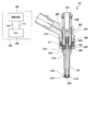
- FIG. 2 shows an example of a vertical cross section of the fuel injection device 101 and a configuration example of the ECU 150 connected to the fuel injection device 101.
- FIG. 3 is an enlarged cross-sectional view of the drive unit structure of the fuel injection device 101.
- the CPU 104 of the ECU 150 captures various signals indicating the state of the engine from various sensors, and determines the width of the injection pulse and the injection timing for controlling the injection amount of the fuel injected from the fuel injection device 101 according to the operating conditions of the engine. Perform the calculation.
- the CPU 104 outputs an injection pulse corresponding to the calculation result to the drive circuit 103.
- the CPU 104 includes an A / D converter (not shown), an I / O port, and the like for capturing signals from various sensors.
- various sensors include a sensor capable of measuring the engine rotation speed (rotation speed) (for example, a sensor for detecting the rotation angle of a crank shaft (not shown) of the engine) and a pressure sensor 102 measuring the fuel pressure in the fuel pipe 105.
- rotation speed for example, a sensor for detecting the rotation angle of a crank shaft (not shown) of the engine
- pressure sensor 102 measuring the fuel pressure in the fuel pipe 105.
- exhaust temperature sensors that measure the exhaust temperature.
- the injection pulse output from the CPU 104 is input to the drive circuit 103 through the signal line 110.
- the drive circuit 103 controls the voltage applied to the solenoid 205 (an example of the coil) of the fuel injection device 101, and supplies a current to the solenoid 205.
- the CPU 104 can communicate with the drive circuit 103 (drive IC 502 in FIG. 5) through the communication line 111, and the drive current generated by the drive circuit 103 depends on the pressure of the fuel supplied to the fuel injection device 101, operating conditions, and the like. Can be controlled to switch, and the drive current and the set value of the time for outputting the current can be changed.
- the fuel injection device 101 is a normally closed valve type solenoid valve (electromagnetic fuel injection device), and includes a solenoid 205 as an example of a coil, a mover 202, a fixed core 207, and a substantially rod-shaped valve body 214. To be equipped. In the fuel injection device 101, when the solenoid 205 is not energized, the valve body 214 is urged in the valve closing direction (downward in the drawing) by the spring 210, and the valve body 214 is in close contact with the valve seat 218 (valve closing). State).
- the mover 202 is urged in the valve opening direction by the return spring 212.
- the force acting on the valve body 214 by the spring 210 is larger than the force by the return spring 212, so that the upper end surface 202A of the mover 202 comes into contact with the brim 302 of the valve body 214 and the mover. 202 is in a stationary state.
- the valve body 214 and the mover 202 are configured to be relatively displaceable, and both are contained in the nozzle holder 201.
- the nozzle holder 201 has an end surface 303 that serves as a spring seat for the return spring 212 inside the nozzle holder 201.
- the urging force of the spring 210 is adjusted at the time of assembly by the pushing amount of the spring retainer 224 fixed to the inner diameter of the fixed core 207.
- a magnetic circuit is composed of a fixed core 207, a mover 202, a nozzle holder 201, and a howing 203.
- a gap 301 is provided between the mover 202 and the fixed core 207.
- a magnetic throttle 211 having a circumferential groove formed on the outer peripheral surface of the nozzle holder 201 is formed in a portion of the nozzle holder 201 corresponding to the gap 301 (outer peripheral side of the gap 301).
- the solenoid 205 is attached to the outer peripheral side of the nozzle holder 201 in a state of being wound around the bobbin 204.
- the rod guide 215 is fixed at a position near the tip of the valve body 214 of the nozzle holder 201 on the valve seat 218 side.
- the valve body 214 has two sliding points, one where the brim 302 of the valve body 214 and the fixed core 207 slide, and the other where the valve body 214 and the rod guide 215 slide. As a result, it is guided and moved in the valve axis direction (vertical direction in the drawing).
- An orifice 216 in which a valve seat 218 and a fuel injection hole 219 are formed is fixed to the tip of the nozzle holder 201.
- the tip of the valve body 214 and the valve seat 218 of the orifice 216 come into contact with each other to seal the internal space (fuel passage) between the nozzle holder 201 and the tip of the valve body 214. It is possible to put it in the closed state (valve closed state).
- the fuel supplied from the fuel pipe 105 to the fuel injection device 101 flows to the tip end side of the valve body 214 through the fuel passage hole 231 when the fuel injection device 101 is in the valve closed state, but the valve of the valve body 214 Since the tip portion on the seat 218 side and the valve seat 218 of the orifice 216 are in contact with each other to seal the fuel injection hole 219, the fuel is not injected to the outside through the fuel injection hole 219.
- a differential pressure is generated between the upper part and the lower part of the valve body 214 due to the fuel pressure, and the differential pressure and the spring obtained by multiplying the fuel pressure by the pressure receiving area at the valve seat position.
- the valve body 214 is pushed in the valve closing direction by the load of 210.
- the mover 202 After the mover 202 collides with the fixed core 207, the mover 202 receives a reaction force from the fixed core 207 and bounces off, but the magnetic attraction force acting on the mover 202 causes the mover 202 to bounce off the fixed core 207. It is sucked into the air, and then stops, and the valve opening operation is completed. At this time, since a force is applied to the mover 202 in the direction of the fixed core 207 by the return spring 212, the time until the rebound converges can be shortened. Since the bounce motion is small, the time during which the gap between the mover 202 and the fixed core 207 becomes large is shortened, and stable operation can be performed even for a smaller injection pulse width.
- a gap is formed between the valve body 214 and the valve seat 218, and fuel is injected from the fuel injection hole 219.
- the fuel supplied through the fuel passage hole 231 passes through the central hole provided in the fixed core 207 and the lower fuel passage hole 305 provided in the mover 202 in the downstream direction (fuel injection hole 219 side). ).
- the mover 202 separates from the valve body 214 and moves in the valve closing direction.
- the return spring 212 returns the valve to the initial position in the closed state. That is, the mover 202 is separated from the valve body 214 at the moment when the valve body 214 is closed.
- the mass of the movable member at the moment when the valve body 214 collides with the valve seat 218 can be reduced by the mass of the mover 202, so that the movable member (substantially the valve body 214) becomes the valve seat 218. It is possible to reduce the collision energy at the time of collision. Therefore, it is possible to suppress the bounce of the valve body 214 caused by the valve body 214 colliding with the valve seat 218.
- the valve body 214 is in a short time at the moment when the mover 202 collides with the fixed core 207 when the valve is opened and the moment when the valve body 214 collides with the valve seat 218 when the valve is closed.
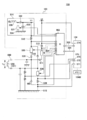
- FIG. 5 is a circuit diagram showing details of the ECU 150 including the drive circuit 103 of the fuel injection device 101.
- the ECU 150 includes a CPU 104 as an example of a control unit and a drive circuit 103.
- a drive IC (Integrated Circuit) 502 is built in the drive circuit 103. It can also be called a control unit including the CPU 501 and the drive IC 502.
- the CPU 104 captures signals (information) indicating the state of the engine output by various sensors such as an A / F (Air Flow) sensor, an oxygen sensor, and a crank angle sensor (not shown).
- the pressure sensor 102 is attached to the fuel pipe 105 upstream of the fuel injection device 101 (see FIG. 1).
- the A / F sensor measures the amount of air flowing into the cylinder 108 (air-fuel ratio).
- the oxygen sensor detects the oxygen concentration of the exhaust gas discharged from the cylinder 108.
- the CPU 104 determines the pulse width (injection pulse width Ti) of the injection pulse for controlling the injection amount of the fuel injected from the fuel injection device 101 according to the operating conditions of the internal combustion engine based on the signals captured from various sensors. Calculates the injection timing.
- the CPU 104 After calculating the injection pulse width Ti (that is, the injection amount) and the injection timing, the CPU 104 outputs an injection pulse having an injection pulse width Ti to the drive IC 502 of the drive circuit 103 through the communication line 504 at an appropriate timing. After that, the drive IC 502 switches between energization and de-energization of the switching elements 505, 506, and 507 to supply a drive current to the fuel injection device 101 (solenoid 205).
- the ECU 150 is equipped with a register and a memory for storing numerical data necessary for engine control such as calculation of injection pulse width.
- the register and the memory may be included in the CPU 104 or may be arranged outside the CPU 104.
- FIG. 5 shows an example in which a memory 104M (an example of a storage medium) is arranged outside the CPU 104.
- the memory 104M may store a computer program for the CPU 104 to control the drive of the fuel injection device 101.
- the CPU 104 reads and executes the computer program recorded in the memory 104M, thereby realizing all or part of the function of controlling the drive of the fuel injection device 101.
- another arithmetic processing device such as an MPU (Micro Processing Unit) may be used.
- the switching elements 505, 506, and 507 are composed of, for example, FETs, transistors, and the like, and can switch between energization and de-energization of the fuel injection device 101.
- the switching element 505 is connected between the booster circuit 514 (high voltage source) that supplies the boost voltage VH and the high voltage side terminal (power supply side terminal 590) of the solenoid 205 included in the fuel injection device 101.
- the boost voltage VH output by the boost circuit 514 is higher than the low voltage (battery voltage VB) supplied to the drive circuit 103 by a low voltage source (for example, a battery) (not shown).
- the voltage value of the battery voltage VB is, for example, about 12 to 14 V.
- the boost voltage VH which is the initial voltage value of the boost circuit 514, is, for example, 60 V, and is generated by boosting the battery voltage VB by the boost circuit 514.
- the booster circuit 514 may be composed of, for example, a DC / DC converter or the like, and as shown in FIG. 5, it is composed of a solenoid 530 (coil), a transistor 531 (switching element), a diode 532, and a capacitor 533. It may be.
- the transistor 531 when the transistor 531 is turned on, the current due to the battery voltage VB flows to the ground potential 534 side via the solenoid 530.
- the transistor 531 is turned off, the high voltage generated in the solenoid 530 is rectified through the diode 532, and the electric charge is accumulated in the capacitor 533.
- the voltage of the capacitor 533 rises to the boost voltage VH.
- the transistor 531 is connected to the drive IC 502 or the CPU 104, and ON / OFF is controlled by the drive IC 502 or the CPU 104.
- the voltage output from the booster circuit 514 is configured to be detected by the drive IC 502 or the CPU 501.
- a diode 535 is provided between the power supply side terminal 590 of the solenoid 205 and the switching element 505 so that a current flows from the booster circuit 514 (high voltage source) in the direction of the solenoid 205 and the ground potential 515.
- a diode 511 is also provided between the power supply side terminal 590 of the solenoid 205 and the switching element 507 so that a current flows from a low voltage source (for example, a battery) in the direction of the solenoid 205 and the ground potential 515. Therefore, while the switching element 506 is energized, no current flows from the ground potential 515 to the battery and the booster circuit 514 via the solenoid 205.
- the switching element 507 is connected between the battery, which is a low voltage source, and the power supply side terminal 590 of the fuel injection device 101.
- the switching element 506 is connected between the terminal on the low voltage side of the fuel injection device 101 and the ground potential 515.
- the drive IC 502 detects the current value flowing through the fuel injection device 101 (each part of the drive circuit 103) by each of the current detection resistors 508, 521, and 513.
- the drive IC 502 switches between energization and de-energization of the switching elements 505, 506, and 507 according to the detected current value, and generates a desired drive current.
- the diodes 509 and 510 are provided to apply a reverse voltage to the solenoid 205 of the fuel injection device 101 to rapidly reduce the current supplied to the solenoid 205.
- the CPU 104 communicates with the drive IC 502 through the communication line 503, and can switch the drive current generated by the drive IC 502 according to the pressure of the fuel supplied to the fuel injection device 101 and the operating conditions. Further, both ends of the resistors 508, 512 and 513 are connected to the A / D conversion port of the drive IC 502, and the voltage applied to both ends of the resistors 508, 512 and 513 can be detected by the drive IC 502.
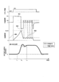
- FIG. 4 is a timing chart showing a time change of a general injection pulse, drive voltage, drive current, and valve body displacement amount when driving the fuel injection device 101.
- the drive IC 502 When an injection pulse (ON) from the CPU 104 is input to the drive IC 502, the drive IC 502 energizes the switching elements 505 and 506 to achieve a high voltage 401 (boost voltage VH boosted by the boost circuit 514) that is higher than the battery voltage. Is applied to the solenoid 205 to start supplying current to the solenoid 205. When the current value to the solenoid 205 reaches the peak current value I peak predetermined in the CPU 104, the drive IC 502 stops applying the high voltage 401.
- a high voltage 401 boost voltage VH boosted by the boost circuit 514
- the drive IC 502 de-energizes the switching element 505, the switching element 506, and the switching element 507.
- the back electromotive force due to the inductance of the fuel injection device 101 energizes the diode 509 and the diode 510, the current is returned to the high-voltage power supply (boost circuit 514) side, and the current supplied to the fuel injection device 101 is reduced.
- the current drops rapidly from the peak current value I peak like 402.
- the switching element 506 may be turned on during the transition period from the peak current value I peak to the current 403 (holding current), and in this case, the current due to the counter electromotive force energy flows to the ground potential 515 side. , The current regenerates in the circuit, a voltage of about 0 V is applied to the solenoid 205, and the current gradually decreases.
- the drive IC 502 When the current value becomes smaller than the predetermined current value 404, the drive IC 502 energizes the switching element 506 and applies the battery voltage VB by energizing / de-energizing the switching element 507 so that the predetermined current 403 is maintained. Provide a switching period to control.
- the fuel injection device 101 is driven by such a drive current profile. From the application of the high voltage 401 to the peak current value I peak , the mover 202 and the valve body 214 start to be displaced at the timing t 41 , and then the mover 202 and the valve body 214 are in the maximum height position. To reach. At the timing t 42 when the mover 202 reaches the maximum height position, the mover 202 collides with the fixed core 207, and the mover 202 makes a bouncing motion with the fixed core 207. Since the valve body 214 is configured to be displaceable relative to the mover 202, the valve body 214 is separated from the mover 202, and the displacement of the valve body 214 overshoots beyond the maximum height position.
- the mover 202 comes to rest at a predetermined maximum height position, and the valve body 214 sits on the mover 202. It stands still at the maximum height position and opens the valve (timing t 43 ).
- the displacement amount of the valve body does not become larger than the maximum height position, and after reaching the maximum height position.
- the displacement amount of the mover and the valve body is the same.
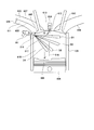
- FIG. 6 shows the configuration inside the cylinder 108 of the engine and around the engine in the first embodiment.
- FIG. 6 is a cross-sectional view of the center of the cylinder 108 of the engine, showing a state immediately after fuel is injected from the tip of the orifice 216 of the fuel injection device 101.
- fuel is directly injected into the cylinder 108.
- the intake valve 605 and the exhaust valve 610 cannot be seen in the cross section at the center of the cylinder 108, but FIG. Then, for the sake of explanation, the intake valve 605 and the exhaust valve 610 are illustrated.
- the engine includes a fuel injection device 101, a spark plug 604, an intake port 607, an exhaust port 608, a piston 609, an intake valve 605, and an exhaust valve 610.
- a cavity 606 (recess) lower than the upper end of the piston 609 on the spark plug 604 side (right side in the drawing) is formed on the surface (crown surface) of the piston 609 on the spark plug 604 side.
- the cavity 606 has a function of temporarily holding an air-fuel mixture of the fuel injected from the fuel injection device 101 and the air taken in from the intake port 607.
- the cavity 606 refers to a portion of the crown surface of the piston 609 on the spark plug 604 side that is deepest from the upper end portion (farthest from the spark plug 604 side).
- the extension line 618 of the alternate long and short dash line drawn from the central gap 617 between the negative electrode 612 and the positive electrode 613 of the spark plug 604 in the stroke direction (sliding direction) of the piston 609 is inside the cavity 606. It is formed in a wide range.
- the central gap 617 is a region including an ignition position where a spark is generated between the negative electrode 612 and the positive electrode 613.
- the cavity 606 is located on the exhaust port 608 side from the intake port 607 side (left side in the drawing) in the direction perpendicular to the stroke direction to the intersection with the extension line 618 of the piston 609 in the stroke direction of the central gap 617. It is formed up to the range (on the right side of the drawing).
- the air-fuel mixture held in the cavity 606 is located directly below the central gap 617 of the spark plug 604 (above the extension line 618).
- the spark plug 604 by pulling the air-fuel mixture of the cavity 606 toward the spark plug 604, it is possible to effectively burn the mixture by ignition by the spark plug 604.
- the intake port 607 is provided with a fixed partition wall 602 that divides the air flow into the upper flow path (first flow path) 620 and the lower flow path (second flow path) 611 of the intake port 607. ..
- a valve 601 for opening / closing (opening / shutting off) the lower flow path 611 is provided upstream of the lower flow path 611.
- the valve 601 is configured so that valve opening / closing can be controlled by the CPU 104 of the ECU 150.
- FIG. 6 shows a state in which the valve 601 is closed.
- FIG. 7 shows a part of the intake system and the exhaust system of the engine in the first embodiment.
- Air is sucked into the combustion chamber 107 of the engine from an intake port (not shown) through an air cleaner 701, a supercharging chamber 704, an intercooler 705, a throttle valve 706, and an intake port 607.
- the air cleaner 701 removes dust in the inhaled air. As a result, it is possible to prevent dust from being sucked into the engine and the inside of the engine from being worn.
- the supercharging room 704 is equipped with a supercharger 702.
- the supercharger 702 includes a compressor 702A that compresses air on the intake side, a turbine 702B that is arranged on the exhaust side and is rotated by the flow of exhaust gas, and a shaft 707 that connects the compressor 702A and the turbine 702B.
- the turbine 702B is rotated according to the flow velocity of the exhaust gas, and the compressor 702A is further rotated via the shaft 707.
- the air that has passed through the air cleaner 701 is compressed by the rotation of the compressor 702A and flows to the intercooler 705 side.
- the air that has passed through the supercharging chamber 704 is compressed by the compressor 702A, so that the temperature rises.
- the intercooler 705 cools the air compressed by the compressor 702A and whose temperature has risen.
- the throttle valve 706 adjusts the amount of air taken into the combustion chamber 107 of the engine.
- the opening degree of the throttle valve 706 is controlled by the ECU 150 based on the opening degree of the accelerator (not shown) or the like.
- the intake port 607 is provided with an intake valve 605, and by opening the intake valve 605 at a predetermined timing, air flows into the combustion chamber 107 of the engine.
- the fuel injection device 101 is arranged so as to inject fuel toward the combustion chamber 107 from the direction intersecting the stroke direction of the piston 609 on the intake port 607 side.
- the inflowing air and the fuel injected from the fuel injection device 101 are mixed to form an air-fuel mixture, which is burned by ignition by the spark plug 604.
- the force generated by the combustion of this air-fuel mixture is transmitted to a crankshaft (not shown) via a piston 609 and a connecting rod (connecting rod) 710.
- the exhaust gas generated by the combustion of the air-fuel mixture in the combustion chamber 107 passes through the exhaust port 608 when the exhaust valve 610 is opened in the expansion stroke, and rotates the turbine 702B of the supercharger 702.
- the exhaust gas that has rotated the turbine 702B passes through the catalyst 703 and is discharged to the outside.
- the catalyst 703 is a three-way catalyst having a catalyst made of, for example, palladium, rhodium, platinum, etc., and HC, NOx, CO (carbon monoxide) contained in the exhaust gas is reduced or oxidized by the catalyst. Remove by letting it. Since the catalyst 703 has a low reducing ability when the temperature is low, for example, immediately after starting the engine, a warm-up is required to warm the temperature of the catalyst 703 at an early stage.
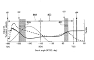
- FIG. 8 shows the relationship between a general crank angle and injection timing during engine operation.
- the horizontal axis represents the angle (crank angle) of the crankshaft after top dead center (ATDC)
- the vertical axis represents the lift amount (Valve lift) of the intake valve 605 and the turbulence speed of the air in the combustion chamber 107. (Turbulent velocity), tumble (tumble) is shown.
- FIG. 8 shows the relationship between a general crank angle and injection timing during engine operation.
- the horizontal axis represents the angle (crank angle) of the crankshaft after top dead center (ATDC)
- the lift amount of the intake valve 605 is shown by a dotted line
- the average value of the turbulence speed of air in the combustion chamber 107 of the engine is shown by a broken line
- the tumble (longitudinal vortex) in the combustion chamber 107 is shown by a solid line.
- the crank angle the TDC (top dead center) of the intake stroke is set to -360 deg
- the BDC (bottom dead center) is set to -180 deg
- the TDC of the compression stroke is set to 0 deg.
- the ECU 150 starts opening the intake valve 605 at the timing t81 when the piston 609 reaches the TDC (-360 deg) and immediately before or at the same time when the exhaust valve 610 closes, and takes in air into the combustion chamber 107.
- the ECU 150 injects the intake stroke 802 (injection pulse width 810) at the timing t82 (crank angle around ⁇ 300 deg) until the intake valve 605 starts opening and reaches the maximum lift amount.
- the ECU 150 injects (injection pulse) of the compression stroke 803 at the timing t83 (near the crank angle -60 deg) before the piston 609 reaches the BDC and the combustion cycle enters the compression stroke 803 and the piston 609 reaches the TDC. Width 811) is performed.
- the ECU 150 ignites with the spark plug 604 at the ignition timing t84 after the piston 609 reaches the TDC, ignites the air-fuel mixture, and burns it.
- FIG. 9 is a projection drawing of the fuel spray injected from the orifice of the fuel injection device when facing the direction of the fuel injection device 101 in the AA'cross section of FIG.
- the fuel injection device 101 is a multi-hole type fuel injection device having a plurality of fuel injection holes.
- the fuel injection device 101 includes, for example, a fuel injection hole that forms a spray D1 that points to the spark plug 604, and two fuel injection holes that form each of the sprays D2 and D6 that are injected in a direction close to the intake valve 605.
- a total of six fuel injection holes are provided, including three fuel injection holes forming each of the sprays D3, D4, and D5 pointing toward the piston 609 side.
- the spraying by the fuel injection device 101 is based on the concept that the spray D4 is put into the cavity 606 to form an air-fuel mixture having a high equivalent ratio in the vicinity of the spark plug 604 in the fuel injection in the compression stroke. There is. Depending on the size of the cavity 606 and the injection timing, the sprays D1, D2, and D6 may be put into the cavity 606.
- the fuel injection device 101 may be configured so that the flow rate of the sprays D3, D4, D5 pointing at the piston 609 is smaller than that of the sprays D1, D2, D6.
- the diameter of the fuel injection holes may be made smaller so that the cross-sectional area of the fuel injection holes of the sprays D3, D4, D5 is smaller than that of the fuel injection holes of the sprays D1, D2, D6.
- FIG. 10 shows the relationship between the time after the engine is stopped and the fuel pressure supplied to the fuel injection device 101.
- the horizontal axis represents the time after the engine is stopped
- the vertical axis represents the fuel pressure.
- HEV Hybrid-Electric Vehicle
- the relationship between the fuel pressure at which the engine is stopped and the time after the engine is stopped is determined by the injection control and the battery filling state (SOC), the fuel pressure at the time of restarting the engine fluctuates. Therefore, it is necessary to control the combustion so that it can be stably burned even when the fuel pressure fluctuates.
- the fuel pressure in the fuel pipe 105 may increase.
- the fuel pressure may increase after the engine is stopped.
- a relief valve (not shown) provided in the fuel pump 106 opens so that the fuel flows to the low pressure side and the pressure in the fuel pipe 105 decreases.
- the fuel pressure in the fuel pipe 105 may increase up to the fuel pressure at which the relief valve opens, and a technique for ensuring combustion stability is important even when the fuel pressure is high.
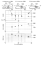
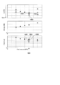
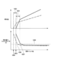
- FIG. 11 shows the relationship between the fuel pressure supplied to the fuel injection device of FIG. 8 and CoV, NOx, and PN.
- the upper side shows the state of spraying when fuel is injected at different fuel pressures (1) to (3) in the combustion chamber 107
- the lower side shows CoV [%], NOx [g / kWh], and And PN [# / cc] measurement results are shown.
- the black square plot points show an example when the injection conditions are constant before and after the change in fuel pressure
- the round plot points indicate the injection in the present embodiment after the change in fuel pressure.
- An example of the case where the control is performed is shown.
- the fuel is injected from the intake side (In on the left side) of the combustion chamber 107 toward the exhaust side (Ex on the right side).
- the CoV decreases and the combustion stability improves. ..
- the reach of the spray becomes longer as the fuel pressure increases, and as shown in the range 1102 (circle indicated by the alternate long and short dash line) of the fuel pressure 25 MPa, the equivalent ratio ⁇ 1 centered on the central gap 617 of the spark plug 604.
- the equivalent ratio ⁇ of the rich air-fuel mixture is set to 1.5 or more, but the value is not limited to this value.
- the penetration force of the spray injected from the fuel injection device 101 is small, so that a rich air-fuel mixture 1114 having an equivalent ratio of ⁇ 1.5 or more cannot be formed in the central gap 617 of the spark plug 604. ..
- the air-fuel mixture 1114 around the central gap 617 of the spark plug 604 becomes lean, which may deteriorate the combustion stability.
- the penetration force of the spray injected from the fuel injection device 101 becomes stronger, and the air-fuel mixture 1116 approaches the exhaust side (Ex) as shown in the range 1103 of the alternate long and short dash line. It ends up. Therefore, a rich air-fuel mixture 1116 cannot be formed around the central gap 617 of the spark plug 604, and combustion may become unstable.
- the piston 609 moves in the direction of top dead center, the volume in the combustion chamber 107 becomes smaller, and the pressure in the combustion chamber 107 (cylinder). Since the internal pressure) rises, it is important to control the penetration force of the spray.
- the crank angle corresponds to 280 degrees or later.
- the fuel injection is close to the ignition timing t84 and the fuel injection is completed by the ignition timing t84.
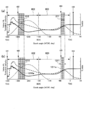
- FIG. 12 shows the relationship between the crank angle and the injection timing in the first embodiment.
- the upper side (a) of FIG. 12 shows the injection control under the same injection conditions as in the case of FIG. 8 for comparison, and the lower side (b) of FIG. 12 shows the case where the fuel pressure is higher than that of the upper side (a).
- An example of injection control is shown.
- the injection amount of the compression stroke 803 is relative to the injection amount of the intake stroke 802 (upper side (a)). It is advisable to control the amount ratio to be small. Specifically, when the fuel pressure becomes high, the injection pulse width 811 (upper side (a)) of the compression stroke 803 is reduced to the injection pulse width 1211 (lower side (b)), and the intake stroke 802. The ratio of the injection pulse widths of the intake stroke 802 and the compression stroke 803 is corrected by the ECU 150 so that the injection pulse width 810 (upper side (a)) of the above is increased to the injection pulse width 1210. In the intake stroke 802 and the compression stroke 803, the timings t82 and t83 for starting injection are the same.
- the penetration force of the spray injected from the fuel injection device 101 is weakened by reducing the injection pulse width 1211 of the compression stroke 803.
- the reach of the spray is shortened, and a rich air-fuel mixture is likely to be formed around the spark plug 604.
- the combustion fluctuation rate (CoV) decreases from the plot point 1104 to the plot point 1105, and the combustion stability can be improved.
- the fuel pressure supplied to the fuel injection device 101 may be detected by using a pressure sensor 102 (see FIG. 1) attached to the fuel pipe 105.
- the PN can be reduced from the plot point 1108 to the plot point 1109, and both CoV and PN can be compatible.
- the temperature around the spark plug 604 before ignition is dominant, but even if the injection amount in the compression stroke is reduced, a rich air-fuel mixture is formed around the spark plug 604.
- the temperature around the spark plug 604 can be reduced by the vaporization cooling effect. Therefore, as shown in (3) 35 MPa of the fuel pressure in FIG. 11, NOx can be reduced from the plot point 1106 to the plot point 1107.
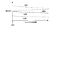
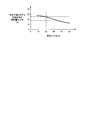
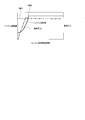
- FIG. 13 shows the relationship between the fuel pressure in the first embodiment and the ratio of the injection amount of the compression stroke to the injection amount of the intake stroke.
- the horizontal axis represents the fuel pressure [MPa]
- the vertical axis represents the ratio [%] of the injection amount of the compression stroke to the injection amount of the intake stroke.
- the higher the fuel pressure the smaller the ratio of the injection amount of the compression stroke to the injection amount of the intake stroke.
- the reachable distance (penetration force) of the spray is adjusted, and the rich air-fuel mixture is centered around the spark plug 604.
- the combustion stability can be improved by forming.
- the correction amount of the injection amount ratio assuming that the injection amount ratio of the compression stroke to the intake stroke at the fuel pressure of 20 MPa is 25%, the ratio of the injection amount of the compression stroke to the intake stroke at the fuel pressure of 35 MPa. Should be corrected so as to be as small as about 18%.
- the injection control method in this embodiment is effective when used for controlling the catalyst warming up when the engine is restarted.
- the ignition timing is retarded from the top dead center, and the ignition is ignited in the expansion stroke to intentionally increase the exhaust loss and raise the temperature of the catalyst.
- the ignition timing is often set in the range of 10 to 30 [deg] after top dead center. Under these injection conditions, combustion tends to be unstable, but by using the injection control of this embodiment, combustion stability can be ensured, and the effect of suppressing PN and NOx can be obtained.
- the fuel is fuel in the fuel injection control device (ECU 150) that injects fuel a plurality of times from the fuel injection device (fuel injection device 101) during one combustion cycle of the internal combustion engine (cylinder 108, piston 609).
- the higher the fuel pressure supplied to the injection device the more the injection (eg injection 1210a) performed before the maximum injection (eg injection 1211a) with the largest injection amount in the latter part of the compression stroke 803 in one combustion cycle.
- It is configured to include a control unit (CPU104) that controls the ratio of the injection amount of the maximum injection to the total value of the injection amount in a direction of decreasing.
- control unit reduces the ratio of the total injection amount in the compression stroke 803 to the total injection amount in the intake stroke 802 as the fuel pressure of the fuel injection device increases. It is controlled to control in the direction of fuel.
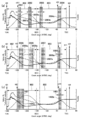
- FIG. 14 shows the relationship between the crank angle and the injection timing for each fuel pressure in the second embodiment.
- An example of the injection control shown in FIG. 8 is also shown on the upper side (a) of FIG. 14 for comparison with FIG.
- the center (b) of FIG. 14 shows an example of injection control (first injection control) when the fuel pressure is higher than that of the upper side (a).
- the lower side (c) of FIG. 14 shows another example (second injection control) of injection control when the fuel pressure is higher than that of the upper side (a).
- the ECU 150 enters the compression stroke 803 in the combustion cycle, and at the timing t83 (near the crank angle -60 deg) before the piston 609 reaches the TDC.
- the injection of the compression stroke was performed.
- the compression stroke is injected at the timing t141 (crank angle -50 deg) later than the timing t83 (crank angle -60 deg) (crank angle -50 deg) ( First injection control).
- the injection pulse width 811 of the compression stroke that is, the injection amount does not change.
- the injection timing (timing t82) of the intake stroke 802 and the injection pulse width 810 are also the same.
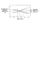
- FIG. 15 shows the relationship between the fuel pressure and the ratio of the injection amount of the compression stroke to the intake stroke in the second embodiment, and the relationship between the fuel pressure and the injection timing of the compression stroke.
- the ratio of the injection amount of the compression stroke to the intake stroke is represented by a solid line
- the injection timing of the compression stroke [deg. ATDC] is represented by a alternate long and short dash line.
- the injection timing of the compression stroke is represented by the crank angle when the TDC of the intake stroke is 0 degree and the TDC of the compression stroke is 360 degrees.
- the injection timing is 315 degrees when the fuel pressure is 15 MPa, and the injection timing is 321 degrees when the fuel pressure is 30 MPa.
- FIG. 16 shows the relationship between the fuel pressure supplied to the fuel injection device in the second embodiment and the combustion volatility (CoV), NOx, and PN.
- the results when the injection is performed under the same injection conditions as those of the upper side (a) of FIGS. 8 and 12 are shown in black squares, and the injections shown in the lower side (b) of FIG. 12 under the condition of high fuel pressure (for example, 35 MPa).
- the results when the control (first reduction of the injection amount ratio) is performed are indicated by circles.
- the results when the injection control (second: decrease in injection amount ratio and delay in injection timing) of FIG. 14 (c) is performed under a condition where the fuel pressure is high (for example, 35 MPa) are indicated by triangles. It is shown by.
- the ECU 150 is under a condition where the fuel pressure is high (center (b) of FIG. 14) and when the fuel pressure is low (FIG. 14 (a)). ),
- the injection timing of the compression stroke 803 is controlled to be delayed.
- the fuel pressure is high, the penetration force of the spray injected from the fuel injection device 101 becomes strong, but by delaying the injection of the compression stroke 803, the pressure in the cylinder 108 increases and the penetration force of the spray becomes weak. Become.
- the effect of holding the air-fuel mixture injected from the fuel injection device 101 around the spark plug 604 can be obtained, and as a result, the combustion stability can be improved.
- the penetration force of the spray is weak, and when the fuel is injected in the latter half of the compression stroke 803, the amount of the rich air-fuel mixture having an equivalent ratio ⁇ of 1.5 or more increases, and the PN increases. There was a case.
- the final injection timing of the compression stroke 803 is delayed, so that the combustion stability can be improved while suppressing the PN.
- the control unit receives from the maximum injection (for example, injection 1402a) of the compression stroke 803 as the fuel pressure of the fuel injection device (fuel injection device 101) increases.
- the ratio of the injection amount of the maximum injection to the total value of the injection amount of the previously performed injection is reduced, and the injection timing of the compression stroke 803 is controlled in a retarding direction.
- the ECU 150 compresses the intake stroke 802 with respect to the intake stroke 802 as shown in the lower side (c) of FIG.
- the ratio of the injection amount of 803 is reduced, and the injection timing of the compression stroke 803 is controlled to be retarded to the timing t141.
- the ratio of the injection amount is such that the injection pulse width 810 of the intake stroke 802 and the injection pulse width 811 of the compression stroke 803 are changed, and the compression stroke 803 with respect to the intake stroke 802 is compared with the upper side (a) of FIG.
- the ECU 150 is set so that the ratio of the injection amount of is small.
- the increase of the rich air-fuel mixture can be suppressed even if the injection timing is delayed, so that the combustion stability is further improved while suppressing the PN. Can be improved.
- the CoV is increased.
- the plot point is reduced from 1602 to 1606, and the PN is reduced from plot point 1604 to plot point 1607.
- the improvement width of CoV is smaller than that of the case where both the ratio of the injection timing and the injection amount is changed (the second injection control in the second embodiment).
- the injection timing of the compression stroke 803 is not retarded, the rich air-fuel mixture having an equivalent ratio ⁇ of 1.5 or more is reduced, so that PN can be significantly suppressed.
- the ECU 150 detects the combustion volatility and PN and switch the injection control according to the engine state based on the detection result. That is, when it is necessary to improve the combustion volatility, the ECU 150 reduces the ratio of the injection amount of the compression stroke 803 to the intake stroke 802 to retard the injection timing of the compression stroke 803. Further, when PN reduction is required, the ECU 150 controls so as to reduce the ratio of the injection amount of the compression stroke 803 to the intake stroke 802.
- the combustion volatility is obtained by directly detecting the in-cylinder pressure in the cylinder, and the PN may be stored in the measuring device or the map data (table) of the PN generation amount for each injection condition in advance in the ECU 10.
- the control unit (CPU104) determines the injection amount of the maximum injection with respect to the total injection amount of the injections performed before the maximum injection of the compression stroke.
- the injection timing of the compression stroke is controlled to retard, and the reduction of the number of unburned particles PN is prioritized, the total injection amount of the injections performed before the maximum injection of the compression stroke is performed. It is preferable to control so as to reduce the ratio of the injection amount of the maximum injection to the value.
- the injection timing of the compression stroke 803 is delayed, and the ratio of the injection amount of the compression stroke to the intake stroke is reduced to reduce the fuel adhesion to the piston 609. The effect of suppressing a rich air-fuel mixture having a high equivalent ratio can be obtained.
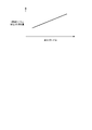
- FIG. 17 shows the relationship between the ignition retard amount and the injection amount per combustion cycle in the third embodiment.
- the retard angle amount (ignition retard amount) of the ignition timing t84 from the TDC of the compression stroke 803 increases, the exhaust loss increases and the thermal efficiency decreases, so that the injection amount per combustion cycle increases. ..
- the injection amount in the compression stroke 803 also becomes relatively large.
- FIG. 18 shows the relationship between the injection pulse width energizing the fuel injection device 101 in the third embodiment and the injection amount and the shot variation of the injection amount.
- the injection amount and the shot variation of the injection amount an example in the case of a low fuel pressure condition is shown by a alternate long and short dash line, and an example in the case of a high fuel pressure condition is shown by a solid line.
- the timing at which the valve body 214 starts valve opening is delayed, and the injection amount in the cylinder 108 increases.
- the timing is delayed from the timing 1801 to the timing 1802 (upper side of FIG. 18).
- the period 1803, 1804 during which the valve body 214 makes a free motion without colliding with the fixed core 207 is compared with the case where the valve body 214 starts closing the valve after the valve body 214 collides with the fixed core 207. Therefore, the shot variation of the injection amount becomes large (lower side of FIG. 18). This is because the valve body 214 is more susceptible to variations such as fluid force and magnetic attraction force under the condition that the valve body 214 is in a free motion as compared with the case where the lift amount of the valve body 214 is determined by the fixed core 207. Because.
- the injection pulse width in which the shot variation of the injection amount is less than the threshold value 1805 is set to the injection pulse width 1806 under the condition that the fuel pressure is low.
- the injection pulse width 1807 under the condition of high fuel pressure is larger.
- the injection amount when compared with the same injection pulse width is also larger when the fuel pressure is high than when the fuel pressure is low.
- the combustion variation increases as the shot variation of the injection amount increases, it is important to appropriately set the ratio of the injection amount of the compression stroke 803 to the intake stroke 802.
- control unit CPU104 of the ECU 150
- the control unit has a function of increasing the fuel pressure supplied to the fuel injection device (fuel injection device 101) as the ignition retard amount increases. Then, as in the first embodiment, the control unit (CPU104) decreases the ratio of the total injection amount in the compression stroke 803 to the total injection amount in the intake stroke 802 as the fuel pressure increases. To control.
- the injection amount in the compression stroke 803 increases relatively. Therefore, even if the fuel pressure is increased and the injection amount of the compression stroke 803 is decreased, it is possible to operate with an injection pulse width in which the shot variation is less than the threshold value 1805. As a result, in addition to reducing the shot variation of the injection amount, the combustion stability can be improved by reducing the ratio of the injection amount of the compression stroke 803 to the intake stroke 802, and both ensuring combustion stability and reducing PN can be achieved. it can.
- the higher the fuel pressure of the fuel injection device fuel injection device 101
- the more the injection timing of the compression stroke 803 may be controlled to be retarded. That is, as in the second injection control in the second embodiment, the higher the fuel pressure, the more the injection timing of the compression stroke 803 is controlled in the retarding direction.
- the injection pulse width is such that the ECU 150 uses the full lift condition in which the shot variation of the injection amount is small and the valve body 214 collides with the fixed core 207. May be set.
- FIG. 19 shows the relationship between the time after restarting the engine in the fourth embodiment and the engine speed and fuel pressure.
- an electrified vehicle equipped with a battery and a motor for example, an HEV
- the engine speed is set to the target value by the motor before the engine restarts. It can be raised to 1901.
- the fuel pressurized by the fuel pump 106 is discharged to the fuel pipe 105, and the fuel pressure in the fuel pipe 105 increases.
- the control unit rotates the internal combustion engine by the motor. It is preferable to control the fuel injection device 101 to inject fuel a plurality of times after the timing when the number increases and the fuel pressure of the fuel injection device 101 exceeds the target value.
- the control method for injecting fuel from the fuel injection device 101 a plurality of times executes any of the first to third or fifth embodiments.
- the motor may not be able to increase the engine speed.
- SOC State of charge
- the motor controls to increase the engine speed, and when the SOC falls below the threshold set preset by the ECU 150, the engine starts, that is, the first to third executions are performed.
- the frequency of engine stops increases compared to vehicles that run solely on the power of an internal combustion engine that is not equipped with a motor.
- the engine may be restarted at either the timing when the SOC falls below the threshold set by the ECU 150 or the timing when the catalyst temperature falls below a certain threshold.
- the ignition retard amount When the engine is started at the timing when the catalyst temperature falls below the threshold value set by the ECU 150, it is advisable to set the ignition retard amount to be larger as the catalyst temperature is lower.
- the amount of ignition retard is increased, the amount of heat discarded in the catalyst increases, so that the temperature of the catalyst can be increased in a short time.
- the ignition retard amount is reduced to control the combustion stability, so that the injection amount per combustion cycle injected from the fuel injection device 101 is increased while ensuring the combustion stability. descend. Therefore, it is possible to suppress HC, NOx, and PN per unit time.
- the motor may be controlled so that the fuel pressure at the time of restarting the engine is higher under the condition where the catalyst temperature is low than under the condition where the catalyst temperature is high.
- the ratio of the final injection amount in the compression stroke 803 can be reduced while enhancing the atomizing effect. Therefore, the final injection timing of the compression stroke 803 can be retarded, and both improvement in combustion stability and reduction in PN can be achieved.
- the control unit (CPU104) increases the ignition retard angle amount as the temperature of the catalyst (catalyst 703) to which the exhaust gas of the internal combustion engine (cylinder 108) is supplied becomes lower.
- the larger the ignition retardation amount the higher the fuel pressure of the fuel injection device 101.
- the control method for injecting fuel from the fuel injection device 101 a plurality of times executes any of the first to third or fifth embodiments.
- the vaporization time of the fuel injected into the cylinder 108 depends on the composition of the fuel supplied to the fuel injection device 101. Since the vaporization rate of heavy fuel is slower than that of light fuel, if fuel is injected at the same timing between light fuel and heavy fuel, a rich mixture with a high equivalent ratio in heavy fuel will increase. In some cases, PN increased.
- the limit temperature for self-ignition generally drops and knocking is likely to occur.
- the ECU 150 may control the injection timing of the compression stroke 803 to be earlier. As a result, the vaporization time can be secured, and the PN can be reduced while securing the equivalent ratio around the spark plug 604.
- the injection control of the heavy fuel and the light fuel may be combined with the control method of any of the first to fourth embodiments.
- the heavy fuel when supplied to the fuel injection device 101 as compared with the light fuel, it is preferable to drive the engine with a motor to raise the fuel pressure before injecting the fuel before starting the engine.
- a motor to raise the fuel pressure before injecting the fuel before starting the engine.
- control unit controls the injection timing of the injection performed before the maximum injection with the largest injection amount in the latter half of the compression stroke in one combustion cycle in the direction of retarding. It is a thing.
- FIG. 20 shows the relationship between the crank angle and the injection timing for each fuel pressure in the fifth embodiment.
- the upper side (a) of FIG. 20 shows the injection control when the fuel pressure supplied to the fuel injection device 101 is low, and the center (b) of FIG. 20 shows the injection control when the fuel pressure is high. Further, on the lower side (c) of FIG. 20, an example of the injection control shown in FIG. 14 (c) is also shown for comparison with FIG. 14 (c).
- control unit controls the injection timing of the intake stroke 802 in a direction that retards the higher the fuel pressure supplied to the fuel injection device (fuel injection device 101).
- the upper side (a) of FIG. 20 shows an example in which two injections 2001a and 2002a are performed in the intake stroke 802, and two injections 2003a and 2004a are performed in the compression stroke 803 as well.
- the injection timing of the first injection 2001a of the intake stroke 802 is the timing t201 later than the timing t82.
- the injections 2001a to 2004a are carried out with injection pulse widths 2001 to 2004, respectively.
- the injection pulse width 2004 of the injection 2004a in the latter stage (the last in the drawing) of the compression stroke 803 is larger than the injection pulse width 2003 of the injection 2003a of the same compression stroke 803.
- the injection performed at the latter stage (particularly at the end) of the compression stroke is the maximum injection amount in the compression stroke.
- the injection timing of the injections 2001a to 2003a before the injection 2004a performed at the end of the compression stroke 803 may be controlled to be retarded as compared with the case where the fuel pressure is low.
- the injection timings of the injections 2005a to 2007a corresponding to the injections 2001a to 2003a of the upper side (a) are retarded. Further, the injections 2005a to 2007a are carried out with injection pulse widths 2005 to 2007 longer than the injection pulse widths 2001 to 2004, respectively. Therefore, the injection pulse width 2008 of the final injection 2008a in the compression stroke 803 is shorter than the injection pulse width 2004 of the injection 2004a.
- the distance between the fuel injection device 101 and the piston 609 can be secured. It is possible to suppress the adhesion of fuel while ensuring the degree. By ensuring the homogeneity of the air-fuel mixture in this way, the generation of a rich air-fuel mixture in the cylinder 108 is suppressed. Further, by suppressing fuel adhesion, PN and HC can be reduced and combustion stability can be improved.
- the amount of fuel adhering to the piston 609 depends on the distance from the fuel injection device 101 to the piston 609. Therefore, when the fuel pressure is high, the injection timing is delayed only for the injection 2005a corresponding to the first injection 2001a of the intake stroke 802 in which the distance between the fuel injection device 101 and the piston 609 is shorter than when the fuel pressure is low. It may be keratinized. Alternatively, the injection timing may be retarded only for the injection 2005a corresponding to the first injection 2001a and the injection 2006a corresponding to the next injection 2002a.
- the later the injection timing the closer the distance between the fuel injection device 101 and the piston 609 becomes. Therefore, by changing the injection of the intake stroke 802 according to the fuel pressure, the exhaust suppression effect can be obtained. Can be enhanced.
- the higher the fuel pressure the earlier the injection timing may be controlled so that the injection 2003a in the compression stroke 803 is closer to the BDC (not shown).
- the injection start timing of the injection 2003a may be advanced to the intake stroke 802.
- the intake stroke 802 has a larger injection amount ratio than the compression stroke 803.
- the ratio of the injection amounts of the injections 2001a, 2002a, 2003a, and 2004a is 0.25: 0.25: as an example. It is advisable to set (correct) as 0.2: 0.3. Further, in the center (b) of FIG. 20, the ratio of the injection amounts of the injections 2005a, 2006a, 2007a, and 2008a is set (corrected) as 0.3: 0.25: 0.25: 0.2 as an example. ). That is, the higher the fuel pressure, the more the ratio of the injection amount of the last injection 2008a in one combustion cycle to the total value of the injection amounts of the injections 2005a, 2006a, 2007a before the last injection 2008a in one combustion cycle. To be smaller.
- the ratio of the injection amount of the intake stroke 802 may be set so that the injection amount of the injection 2001a or 20005a to be injected at the timing when the turbulence speed is large becomes the largest. As a result, the mixing of air and fuel is promoted, and the homogeneity can be improved. Further, in one combustion cycle, the ratio of the injection amount of the last injection of the compression stroke 803, 2004a or 2008a, to the intake stroke 802 may be set to be the smallest. By reducing the injection amount of the compression stroke 803, the amount of the rich air-fuel mixture formed around the spark plug 604 can be minimized, and the equivalent ratio is 1.5 while ensuring combustion stability. The amount of the rich air-fuel mixture as described above can be suppressed, and PN can be reduced.
- control unit is further performed before the maximum injection (injection 2004a, 2008a) with the largest injection amount in the latter half of the compression stroke 803 in one combustion cycle. Control in the direction of widening the interval between injections.
- the injection timing may be changed so that the injection intervals of the first and second injections and the second and third injections are shortened.
- the injection timing is delayed as compared with the case where the fuel pressure is low, and the timing at which the second or third injection is completed is earlier. Therefore, the fuel can be injected at the turbulent speed of the intake stroke 802 and the timing when the tumble is strong, and both PN suppression and improvement of combustion stability by improving homogeneity can be achieved at the same time.
- the injection interval of the first or second injection and the injection interval of the second and third injections are smaller when the fuel pressure is high than when the fuel pressure is low. You may control it.
- the fuel is injected at a timing when the turbulence speed is higher than in the third and subsequent injections, so that the effect of reducing the injection interval is enhanced.
- the injection interval between the first and second injections is controlled to be smaller than the injection interval between the second injection and the third injection when the fuel pressure is low. You may.
- the injection of the intake stroke 802 is the compression stroke 803 as in the injection 2003a and the injection 2007a. It may come in the first half.
- the fuel pressure is higher than the ratio of the injection amount of the last injection 2004a in one combustion cycle under the condition where the fuel pressure is low and the injections 2001a, 2002a, 2003a which are the injections before the injection 2004a. May be controlled by the ECU 150 so that the injection amount ratio of the last injection 2008a in one combustion cycle is smaller than that of the injections 2005a, 2006a, and 2007a.
- the ratio of the injection amount closest to the ignition timing t84 at the end of one combustion cycle is made smaller than the total value of the other injection amounts, so that the fuel pressure becomes high. Even if there is, it is possible to suppress the penetration force of the spray and form a rich air-fuel mixture around the spark plug 604 at the ignition timing t84. As a result, combustion stability can be improved.
- each of the above-described embodiments describes in detail and concretely the configurations of the fuel injection device and the fuel injection system in order to aid the understanding of the present invention, and is not necessarily limited to those including all the components described. ..
- each of the above configurations, functions, processing units, etc. may be realized by hardware, for example, by designing a part or all of them with an integrated circuit.
- FPGA Field Programmable Gate Array
- ASIC Application Specific Integrated Circuit
- Fuel injection system 101 ... Fuel injection device, 102 ... Pressure sensor, 105 ... Fuel piping, 107 ... Combustion chamber, 108 ... Cylinder, 609 ... Piston, 104 ... CPU, 104M ... Memory, 150 ... ECU, 802 ... Intake Stroke, 803 ... Compression stroke, 1401a-1402a, 2001a-2008a ... Injection, 810-811,1210-1211, 1401-1402, 2001-2008 ... Injection pulse width, t84 ... Ignition timing
Landscapes
- Engineering & Computer Science (AREA)
- Chemical & Material Sciences (AREA)
- Combustion & Propulsion (AREA)
- Mechanical Engineering (AREA)
- General Engineering & Computer Science (AREA)
- Signal Processing (AREA)
- Electrical Control Of Air Or Fuel Supplied To Internal-Combustion Engine (AREA)
- Electrical Control Of Ignition Timing (AREA)
- Control Of Vehicle Engines Or Engines For Specific Uses (AREA)
- Combined Controls Of Internal Combustion Engines (AREA)
Abstract
環境条件が変化した場合であっても、点火プラグ周りにリッチな混合気を形成し、かつ排気を抑制する。本発明の一態様は、内燃機関の1燃焼サイクル中に燃料噴射装置101から複数回燃料を噴射する燃料噴射制御装置150において、燃料噴射装置101に供給する燃料圧力が高いほど、1燃焼サイクルにおける圧縮行程803の後期の中で一番大きな噴射量を伴う最大噴射よりも前に行われる噴射の噴射量の合計値に対する、最大噴射の噴射量の比率を小さくする方向に制御する制御部104、を備える。
Description
本発明は、内燃機関の燃焼室内に燃料を噴射する燃料噴射装置を制御する燃料噴射制御装置及び燃料噴射制御方法に関する。
近年、地球温暖化防止や、化石燃料の資源枯渇抑制の観点から、内燃機関のエンジンでは、モード走行時の二酸化炭素(CO2)を低減することから求められる。CO2低減のためには燃料の消費量を抑制する必要があり、燃料が空気に対して希薄な状態で燃焼されるリーン燃焼が有効な技術である。特にリーン燃焼では、エンジン筒内の等量比が薄い状態で混合気に着火する必要があるため、燃焼速度が緩慢となり、燃焼が不安定となりやすい。このため、圧縮行程の後期に燃料を噴射して点火プラグ近傍を僅かに燃料がリッチな状態とすることで燃焼を安定化させる弱成層燃焼が有効な手段である。
近年、排気規制の強化に伴い、モード走行時のエンジンからの排気中の未燃焼粒子(PM:Particulate Matter)の総量と、その個数である未燃焼粒子数(PN:Particulate Number)と、HC(炭化水素)と、NOx(窒素酸化物)とを低減することが求められている。排気中のPN及びHCは、燃料噴射装置から噴射した燃料が、燃焼室のピストン及びボア壁面に付着することで生じる。また、未燃焼粒子数は、点火の直前における空気と燃料との比である当量比が大きい、すなわち、燃料が濃い領域があると増加する傾向にある。このことから、PNとHCを抑制するためには、燃料付着を低減することが有効である。HCは、触媒が活性化していないエンジン始動時に多く排出されるため、点火タイミングを暖機完了後のアイドルよりもリタード(遅角)させ、排気損失を大きくして排気の温度を高くして触媒を早期に昇温させる技術が求められる。
点火リタードでは、圧縮行程が終了し、ピストンが上死点から下死点に向かうまでの膨張期間で点火するため、燃焼が不安定となり易い。したがって、確実に点火するためには、点火プラグ周りに点火に必要な濃い(リッチな)混合気を形成する技術が求められる。
点火するタイミングにおいて、点火プラグの周りにリッチな混合気を形成するためには、ピストンの冠面にキャビティを形成し、圧縮行程に燃料を噴射してキャビティに入れた混合気を巻き上げることで、点火プラグ周りに混合気を集める技術が有効である。
点火するタイミングにおいて、点火プラグの周りにリッチな混合気を形成するためには、ピストンの冠面にキャビティを形成し、圧縮行程に燃料を噴射してキャビティに入れた混合気を巻き上げることで、点火プラグ周りに混合気を集める技術が有効である。
このためには、貫徹力が強い燃料を噴射して、混合気を点火プラグに確実に届かせる必要がある。また、噴霧の貫徹力は、燃料噴射装置に供給される燃料の圧力に依存して変化するため、燃料圧力などの環境条件の変化に応じて噴射条件を変化させる必要がある。
上記のような環境条件の変化に対応する手段として、特許文献1に開示されている方法がある。特許文献1では、燃料圧力が高い場合には、圧縮行程の2つの噴射のいずれか一方の噴射を、最大高さ位置(フルリフト)よりも低い高さ位置(ハーフリフト)で制御する方法が開示されている。
エンジン始動後の触媒暖気時には、燃焼安定性に必要な点火プラグ周りの混合気を確保するため、圧縮行程に燃料を噴射する必要がある。特に燃料噴射装置が燃焼室の側面に取り付けられているサイド噴射の場合、燃料噴射装置と点火プラグとの距離が長いため、点火タイミングにおいて、点火プラグ周りに混合気を形成するためには、圧縮行程に噴射する噴射量を多くする必要がある。圧縮行程では、燃料噴射装置とピストン冠面との幾何学的な距離が短いため、噴射した燃料がピストンに付着しやすく、燃焼室から排出されるHCやPNが多くなってしまう課題がある。
触媒暖気時においては、エンジンを始動した直後であるので、燃料噴射装置に供給する燃料の圧力が低い状態から目標とする圧力まで徐々に上昇する。このような環境条件が変化する、例えば燃料噴射装置に供給される燃料の圧力が変化する場合、環境条件が変化する前と同じ噴射条件で燃料を噴射すると、点火プラグ周りに点火に必要な濃い(リッチな)混合気を形成できない場合や、PN、HC、NOxなどの排気が増加する場合があった。
上記の状況から、環境条件が変化した場合であっても、点火プラグ周りにリッチな混合気を形成し、かつ排気を抑制する手法が要望されていた。
上記課題を解決するために、内燃機関の1燃焼サイクル中に燃料噴射装置から複数回燃料を噴射する燃料噴射制御装置において、燃料噴射装置の燃料圧力が高いほど、1燃焼サイクルにおける圧縮行程の後期の中で一番大きな噴射量を伴う最大噴射よりも前に行われる噴射の噴射量の合計値に対する、最大噴射の噴射量の比率を小さくする方向に制御する制御部、を備える。
本発明の少なくとも一態様によれば、燃料圧力などの環境条件が変化した場合であっても燃料噴射装置の噴霧の貫徹力を調整し、点火プラグ周りにリッチな混合気を形成し、かつ排気を抑制することができる。
上記した以外の課題、構成及び効果は、以下の実施形態の説明により明らかにされる。
上記した以外の課題、構成及び効果は、以下の実施形態の説明により明らかにされる。
以下、本発明を実施するための形態の例について、添付図面を参照して説明する。本明細書及び添付図面において実質的に同一の機能又は構成を有する構成要素については、同一の符号を付して重複する説明を省略する。
<1.第1の実施形態>[燃料噴射システムの構成]
本発明の第1の実施形態に係る燃料噴射制御装置が適用された燃料噴射システムについて、図1~図13を用いて説明する。
本発明の第1の実施形態に係る燃料噴射制御装置が適用された燃料噴射システムについて、図1~図13を用いて説明する。
始めに、図1を用いて、第1の実施形態に係る燃料噴射システムの概略を説明する。
図1は、第1の実施形態に係る燃料噴射システムの一例を示した概略図である。燃料噴射システム1は、本発明を筒内直接噴射式エンジン(内燃機関の一例)に適用した例であるが、本発明はこの例に限らない。本明細書において、筒内直接噴射式エンジンを単に「エンジン」と称することがある。
図1は、第1の実施形態に係る燃料噴射システムの一例を示した概略図である。燃料噴射システム1は、本発明を筒内直接噴射式エンジン(内燃機関の一例)に適用した例であるが、本発明はこの例に限らない。本明細書において、筒内直接噴射式エンジンを単に「エンジン」と称することがある。
本実施形態に係る筒内直接噴射式エンジンは、4つの気筒108(エンジンシリンダ)を備える。燃料噴射システム1は、4つの気筒108に対応して、4つの燃料噴射装置101A~101Dと、燃料噴射制御装置の一例としてのECU(Engine Control Unit)150を備える。以下の説明において、燃料噴射装置101A~101Dを区別しない場合には、「燃料噴射装置101」と称する。
燃料噴射システム1の各気筒108には、燃料噴射装置101A~101Dが、その燃料噴射孔219(後述する図2参照)から霧状の燃料が燃焼室107に直接噴射されるように設置されている。図示しない燃料タンクに貯留された燃料は、燃料ポンプ106によって昇圧されて高圧配管120を介してレール状の燃料配管105に送出され、燃料配管105から各燃料噴射装置101A~101Dに配送されるようになっている。燃料配管105の一端部には、燃料配管105内の燃料の圧力(燃料圧力:燃圧と称する)を測定する圧力センサ102が設置されている。
燃料配管105内の燃料圧力は、燃料ポンプ106によって吐出された燃料の流量と、各燃料噴射装置101によって各燃焼室107内に噴射された燃料の噴射量とのバランスによって変動する。
本実施形態では、ECU150が、圧力センサ102から出力されるセンサ情報(燃圧値を示す情報)に基づいて、燃料配管105内の燃圧が所定の目標圧力値となるように、燃料ポンプ106の燃料の吐出量を制御する。
燃料噴射装置101による燃料の噴射は、ECU150のCPU104(制御部の一例)から送出される噴射パルス(図4参照)によって制御される。すなわち、燃料の噴射量は、燃料噴射装置101に供給される噴射パルスのパルス幅(噴射パルス幅)に基づいて決定される。この噴射パルス幅の指令が、燃料噴射装置101ごとに設けられた駆動回路103に入力される。駆動回路103は、CPU104からの指令に基づいて駆動電流の波形を決定し、噴射パルス(パルス幅)に基づく時間だけ燃料噴射装置101に上記波形の駆動電流を供給する。
すなわち、燃料噴射制御装置の制御部(ECU150のCPU104)は、後述する1燃焼サイクルにおける噴射間の噴射量の比率を変更するときに、噴射パルスのパルス幅に基づいて燃料噴射装置(燃料噴射装置101)を駆動する電流波形を変更する。このように、噴射パルスのパルス幅に基づいて電流波形を変更することで、燃料噴射装置が噴射する燃料の噴射量を調整することができる。また、CPU104から駆動回路103に送出する噴射パルスのタイミング(オフ/オンの切り替わり)を変更することで、燃料噴射装置が燃料を噴射するタイミングを調整することができる。
なお、ECU150の駆動回路103とCPU104とは、一体の部品や基板として実装されてもよい。また、駆動回路103が、ECU150とは別体でもよい。
次に、燃料噴射装置101及びECU150の構成と基本的な動作を説明する。
図2は、燃料噴射装置101の縦断面の例と、この燃料噴射装置101に接続されるECU150の構成例を示す。
図3は、燃料噴射装置101の駆動部構造の断面拡大図である。
図2は、燃料噴射装置101の縦断面の例と、この燃料噴射装置101に接続されるECU150の構成例を示す。
図3は、燃料噴射装置101の駆動部構造の断面拡大図である。
ECU150のCPU104は、エンジンの状態を示す各種信号を各種センサから取り込んで、エンジンの運転条件に応じて燃料噴射装置101から噴射する燃料の噴射量を制御するための噴射パルスの幅や噴射タイミングの演算を行う。CPU104は、演算結果に対応する噴射パルスを駆動回路103に出力する。
CPU104は、各種センサからの信号を取り込むための図示しないA/D変換器、I/Oポート等を備えている。各種センサとしては、例えば、エンジン回転数(回転速度)を測定可能なセンサ(例えば、エンジンの図示しないクランク軸の回転角を検出するセンサ)や、燃料配管105内の燃圧を測定する圧力センサ102や、排気温度を測定する排気温度センサ等がある。
CPU104から出力される噴射パルスは、信号線110を通して駆動回路103に入力される。駆動回路103は、燃料噴射装置101のソレノイド205(コイルの一例)に印加する電圧を制御し、ソレノイド205に電流を供給する。CPU104は、通信ライン111を通して、駆動回路103(図5の駆動IC502)と通信可能であり、燃料噴射装置101に供給されている燃料の圧力や運転条件等によって、駆動回路103により生成する駆動電流を切り替えるように制御したり、駆動電流及び電流を出力する時間の設定値を変更したりすることができる。
燃料噴射装置101は、通常時閉弁型の電磁弁(電磁式燃料噴射装置)であり、コイルの一例としてのソレノイド205と、可動子202と、固定コア207と、略棒状の弁体214とを備える。燃料噴射装置101は、ソレノイド205が通電されていない状態では、スプリング210によって弁体214が閉弁方向(図面下方向)に付勢され、弁体214が弁座218に密着した状態(閉弁状態)となっている。
可動子202は、戻しばね212によって開弁方向へ付勢されている。閉弁状態においては、スプリング210により弁体214に作用する力が、戻しばね212による力に比べて大きいため、可動子202の上端面202Aが弁体214のつば部302に接触し、可動子202は静止した状態となる。
弁体214と可動子202とは、相対変位可能に構成されており、共にノズルホルダ201に内包されている。ノズルホルダ201は、その内部に戻しばね212のばね座となる端面303を有している。スプリング210による付勢力は、固定コア207の内径に固定されるバネ押さえ224の押し込み量によって組み立て時に調整されている。
燃料噴射装置101においては、固定コア207、可動子202、ノズルホルダ201、及びハウシング203によって磁気回路が構成されている。可動子202と、固定コア207との間には、空隙301が設けられている。ノズルホルダ201の空隙301に対応する部分(空隙301の外周側)には、ノズルホルダ201の外周面に周方向の溝部が形成されてなる磁気絞り211が形成されている。
ソレノイド205は、ボビン204に巻き付けられた状態でノズルホルダ201の外周側に取り付けられている。ノズルホルダ201の弁体214の弁座218側の先端部の近傍となる位置には、ロッドガイド215が固定されている。このような構成により、弁体214は、弁体214のつば部302と固定コア207とが摺動する箇所と、弁体214とロッドガイド215とが摺動する箇所との2つの摺動箇所により、弁軸方向(図面上下方向)にガイドされて動くようになっている。
ノズルホルダ201の先端部には、弁座218と燃料噴射孔219とが形成されたオリフィス216が固定されている。このような構成により、弁体214の先端部と、オリフィス216の弁座218とが接触することにより、ノズルホルダ201と弁体214の先端部との間の内部空間(燃料通路)を封止した状態(閉弁状態)にできるようになっている。
燃料配管105から燃料噴射装置101に供給された燃料は、燃料噴射装置101が閉弁状態の場合においては、燃料通路孔231を通って弁体214の先端側まで流れるが、弁体214の弁座218側の先端部分とオリフィス216の弁座218とが接触して燃料噴射孔219を封止しているので、燃料噴射孔219を介して外部に噴射されない。燃料噴射装置101が閉弁状態の場合には、燃料圧力によって弁体214の上部と下部との間に差圧が生じ、燃料圧力と弁座位置における受圧面積とを乗じて求まる差圧力及びスプリング210の荷重によって弁体214が閉弁方向に押されている。
そして、燃料噴射装置101が閉弁状態の場合において、ソレノイド205への電流の供給が開始されると、磁気回路に磁界が生じ、固定コア207と可動子202との間に磁束が通過して、可動子202に磁気吸引力が作用する。可動子202に作用する磁気吸引力が、差圧力及びスプリング210による荷重を超えるタイミングで、可動子202は、固定コア207に向かう方向に変位を開始する。そして、可動子202の移動に伴い弁体214が開弁動作を開始した後、可動子202は固定コア207に近づくように移動し、可動子202が固定コア207に衝突する。
可動子202が固定コア207に衝突した後には、可動子202は固定コア207からの反力を受けて跳ね返る動作をするが、可動子202に作用する磁気吸引力によって可動子202は固定コア207に吸引され、やがて停止し、開弁動作を終了する。このとき、可動子202には、戻しばね212によって固定コア207の方向に力が作用しているため、跳ね返りが収束するまでの時間を短縮できる。跳ね返り動作が小さいことで、可動子202と固定コア207との間のギャップが大きくなってしまう時間が短くなり、より小さい噴射パルス幅に対しても安定した動作が行えるようになる。
このようにして開弁動作を終えた可動子202及び弁体214は、開弁状態で静止する。開弁状態では、弁体214と弁座218との間には隙間が生じており、燃料噴射孔219より燃料が噴射される。なお、燃料通路孔231を通って供給される燃料は、固定コア207に設けられた中心孔と、可動子202に設けられた下部燃料通路孔305を通過して下流方向(燃料噴射孔219側)へ流れる。
この後、燃料噴射装置101のソレノイド205への通電が断たれると、磁気回路中に生じていた磁束が消滅し、可動子202に作用する磁気吸引力も消滅する。このように可動子202に作用する磁気吸引力が消滅すると、可動子202及び弁体214は、スプリング210の荷重と、差圧力とによって、弁座218に接触する閉弁位置に押し戻される。
このように、弁体214が開弁状態から閉弁状態となる際には、弁体214が弁座218と接触した後、可動子202が弁体214から分離して閉弁方向に移動して、或る程度の時間運動した後に、戻しばね212の作用によって、閉弁状態の初期位置まで戻される。すなわち、弁体214が閉弁状態となる瞬間に可動子202が、弁体214から離間する。これにより、弁体214が弁座218と衝突する瞬間の可動部材の質量を可動子202の質量分だけ低減することができるため、可動部材(実質的には弁体214)が弁座218と衝突する際の衝突エネルギーを小さくすることが可能である。したがって、弁体214が弁座218に衝突することによって生じる弁体214のバウンドを抑制できる。
本実施形態に係る燃料噴射装置101では、開弁時に可動子202が固定コア207と衝突した瞬間、及び、閉弁時に弁体214が弁座218と衝突した瞬間の短い時間において、弁体214と可動子202との間で相対的な変位を生じることにより、可動子202の固定コア207に対するバウンドや、弁体214の弁座218に対するバウンドを抑制することができる。
次に、第1の実施形態に係るECU150の構成について説明する。
図5は、燃料噴射装置101の駆動回路103を含むECU150の詳細を示した回路図である。
図5は、燃料噴射装置101の駆動回路103を含むECU150の詳細を示した回路図である。
ECU150は、制御部の一例としてのCPU104と、駆動回路103とを備えている。例えば駆動回路103には、駆動IC(Integrated Circuit)502が内蔵されている。CPU501と駆動IC502を含めて、制御部と言うこともできる。CPU104は、圧力センサ102に加え、図示しないA/F(Air Flow)センサ、酸素センサ、及びクランク角センサ等の各種センサが出力するエンジンの状態を示す信号(情報)を取り込む。
圧力センサ102は、燃料噴射装置101の上流の燃料配管105に取り付けられている(図1参照)。A/Fセンサは、気筒108への流入空気量(空燃比)を測定する。酸素センサは、気筒108から排出された排気ガスの酸素濃度を検出する。CPU104は、各種センサから取り込んだ信号に基づいて、内燃機関の運転条件に応じて燃料噴射装置101から噴射する燃料の噴射量を制御するための噴射パルスのパルス幅(噴射パルス幅Ti)や、噴射タイミングの演算を行う。
そして、CPU104は、噴射パルス幅Ti(すなわち噴射量)や噴射タイミングを演算後、通信ライン504を通して駆動回路103の駆動IC502に、適切なタイミングで噴射パルス幅Tiの噴射パルスを出力する。その後、駆動IC502によって、スイッチング素子505,506,507の通電/非通電を切り替えて燃料噴射装置101(ソレノイド205)へ駆動電流を供給する。
ECU150には、噴射パルス幅の演算等のエンジンの制御に必要な数値データを記憶させるために、レジスタ及びメモリが搭載されている。レジスタ及びメモリは、CPU104に内包されていてもよいし、CPU104の外部に配置されてもよい。図5では、CPU104の外部にメモリ104M(記憶媒体の一例)が配置された例が示されている。
メモリ104Mには、CPU104が燃料噴射装置101の駆動を制御するためのコンピュータープログラムが格納されていてもよい。この場合、CPU104が、メモリ104Mに記録されたコンピュータープログラムを読み出して実行することにより、燃料噴射装置101の駆動を制御する機能の全部又は一部が実現される。なお、CPU104に代えてMPU(Micro Processing Unit)等の他の演算処理装置を用いてもよい。
スイッチング素子505,506,507は、例えばFETやトランジスタ等によって構成され、燃料噴射装置101への通電/非通電を切り替えることができる。
スイッチング素子505は、昇圧電圧VHを供給する昇圧回路514(高電圧源)と、燃料噴射装置101が備えるソレノイド205の高電圧側の端子(電源側端子590)との間に接続されている。昇圧回路514が出力する昇圧電圧VHは、不図示の低電圧源(例えばバッテリ)が駆動回路103に供給する低電圧(バッテリ電圧VB)よりも高い。
ここで、バッテリ電圧VBの電圧値は、例えば、12~14V程度である。昇圧回路514の初期電圧値である昇圧電圧VHは、例えば60Vであり、バッテリ電圧VBを昇圧回路514によって昇圧することで生成される。
ここで、バッテリ電圧VBの電圧値は、例えば、12~14V程度である。昇圧回路514の初期電圧値である昇圧電圧VHは、例えば60Vであり、バッテリ電圧VBを昇圧回路514によって昇圧することで生成される。
昇圧回路514は、例えばDC/DCコンバータ等により構成するようにしてもよく、図5に示すように、ソレノイド530(コイル)、トランジスタ531(スイッチング素子)、ダイオード532、及びコンデンサ533で構成するようにしてもよい。図5に示す昇圧回路514の場合、トランジスタ531をONにすると、バッテリ電圧VBによる電流はソレノイド530を介して接地電位534側へ流れる。一方、トランジスタ531をOFFにすると、ソレノイド530に発生する高い電圧がダイオード532を通して整流され、コンデンサ533に電荷が蓄積される。トランジスタ531のON/OFFが繰り返し実行されることで、コンデンサ533の電圧が昇圧電圧VHまで上昇する。トランジスタ531は、駆動IC502もしくはCPU104と接続されて、駆動IC502もしくはCPU104によりON/OFFが制御される。昇圧回路514から出力される電圧は、駆動IC502もしくはCPU501で検出できるように構成されている。
ソレノイド205の電源側端子590とスイッチング素子505との間には、昇圧回路514(高電圧源)から、ソレノイド205及び接地電位515の方向へ電流が流れるようにダイオード535が設けられている。また、ソレノイド205の電源側端子590とスイッチング素子507との間にも、低電圧源(例えばバッテリ)から、ソレノイド205及び接地電位515の方向へ電流が流れるようにダイオード511が設けられている。
したがって、スイッチング素子506が通電している間は、接地電位515からソレノイド205を介して、バッテリ及び昇圧回路514へ向けては電流が流れない構成となっている。
したがって、スイッチング素子506が通電している間は、接地電位515からソレノイド205を介して、バッテリ及び昇圧回路514へ向けては電流が流れない構成となっている。
また、スイッチング素子507は、低電圧源であるバッテリと燃料噴射装置101の電源側端子590との間に接続されている。スイッチング素子506は、燃料噴射装置101の低電圧側の端子と接地電位515との間に接続されている。駆動IC502は、電流検出用の抵抗508,512,513の各々により、燃料噴射装置101(駆動回路103の各部)に流れている電流値を検出する。駆動IC502は、検出した電流値によって、スイッチング素子505,506,507の通電/非通電を切り替え、所望の駆動電流を生成している。
ダイオード509,510は、燃料噴射装置101のソレノイド205に逆電圧を印加して、ソレノイド205に供給されている電流を急速に低減するために備え付けられている。CPU104は、通信ライン503を通して、駆動IC502と通信を行っており、燃料噴射装置101に供給する燃料の圧力や運転条件に応じて、駆動IC502によって生成する駆動電流を切り替えることが可能である。また、抵抗508,512,513の両端は、駆動IC502のA/D変換ポートに接続されており、抵抗508,512,513の両端にかかる電圧を駆動IC502で検出できるように構成されている。
次に、CPU104から出力される噴射パルスと、燃料噴射装置101が備えるソレノイド205の端子両端の駆動電圧と、駆動電流(励磁電流)と、燃料噴射装置101の弁体214の変位量(弁体挙動)との関係について説明する。
図4は、燃料噴射装置101を駆動する際における一般的な、噴射パルス、駆動電圧、駆動電流、及び弁体変位量についての時間変化を示したタイミングチャートである。
駆動IC502にCPU104からの噴射パルス(ON)が入力されると、駆動IC502は、スイッチング素子505,506を通電してバッテリ電圧よりも高い高電圧401(昇圧回路514により昇圧された昇圧電圧VH)をソレノイド205に印加して、ソレノイド205への電流の供給を開始する。駆動IC502は、ソレノイド205への電流値が予めCPU104において定められたピーク電流値Ipeakに到達すると、高電圧401の印加を停止する。
その後、駆動IC502は、スイッチング素子505、スイッチング素子506、及びスイッチング素子507を非通電にする。この結果、燃料噴射装置101のインダクタンスによる逆起電力によって、ダイオード509とダイオード510とが通電し、電流が高圧電源(昇圧回路514)側へ帰還され、燃料噴射装置101に供給されていた電流は、電流402のようにピーク電流値Ipeakから急速に低下する。
なお、ピーク電流値Ipeakから電流403(保持電流)への移行期間にスイッチング素子506をONにするようにしてもよく、このようにすると、逆起電力エネルギーによる電流は接地電位515側に流れ、電流が回路内を回生し、ソレノイド205には、ほぼ0Vの電圧が印加されて電流は緩やかに低下する。
電流値が所定の電流値404より小さくなると、駆動IC502は、スイッチング素子506を通電し、スイッチング素子507の通電/非通電によってバッテリ電圧VBの印加を行い、所定の電流403が保たれるように制御するスイッチング期間を設ける。
ここで、燃料噴射装置101に供給される燃料圧力が大きくなると、弁体214に作用する閉弁方向の流体力が増加し、弁体214が目標開度に到達するまでの時間が長くなる。この結果、ピーク電流Ipeakの到達時間に対して目標開度への到達タイミングが遅れる場合があるが、電流を電流402のように急速に低減すると、可動子202に働く磁気吸引力も急速に低下するため、弁体214の挙動が不安定となり、場合によっては通電中にも関わらず閉弁を開始してしまう場合がある。これに対し、ピーク電流Ipeakから電流403への移行中にスイッチング素子505をONにして電流を緩やかに減少させるようにすると、磁気吸引力の急速な低下を抑制できる。それにより、高燃料圧力での弁体214の安定性を確保でき、噴射量のばらつきを抑制することが可能となる。
このような駆動電流のプロファイルにより、燃料噴射装置101は駆動される。高電圧401の印加からピーク電流値Ipeakに達するまでの間に、可動子202及び弁体214がタイミングt41で変位を開始し、その後、可動子202及び弁体214が最大高さ位置に到達する。可動子202が最大高さ位置に到達したタイミングt42で、可動子202が固定コア207に衝突し、可動子202が固定コア207との間でバウンド動作を行う。弁体214は可動子202に対して相対変位可能に構成されているため、弁体214は可動子202から離間し、弁体214の変位は、最大高さ位置を超えてオーバーシュートする。その後、電流403によって生成される磁気吸引力と戻しばね212の開弁方向への力によって、可動子202は、所定の最大高さ位置で静止し、弁体214は可動子202に着座して最大高さ位置で静止し、開弁状態となる(タイミングt43)。
なお、弁体と可動子とが一体となっている可動弁を持つ燃料噴射装置の場合には、弁体の変位量は、最大高さ位置よりも大きくならず、最大高さ位置に到達後の可動子と弁体の変位量は同等となる。
次に、第1の実施形態に係るエンジンの気筒108内及びエンジン周囲の構成について説明する。
図6は、第1の実施形態におけるエンジンの気筒108内及びエンジン周囲の構成を示す。図6は、エンジンの気筒108内の中心における断面図であり、燃料噴射装置101のオリフィス216の先端部から燃料が噴射された直後の状態を示している。筒内直接噴射式エンジンでは、気筒108内に直接燃料が噴射される。なお、吸気バルブ605を2個備え、排気バルブ610を2個備えている筒内直接噴射式エンジンでは、気筒108内の中心における断面では、吸気バルブ605及び排気バルブ610は見えないが、図6では、説明上、吸気バルブ605と排気バルブ610とを図示している。
エンジンは、燃料噴射装置101と、点火プラグ604と、吸気ポート607と、排気ポート608と、ピストン609と、吸気バルブ605と、排気バルブ610とを備える。
ピストン609の点火プラグ604側の面(冠面)には、ピストン609の点火プラグ604側(図中右側)の上端部よりも低いキャビティ606(凹部)が形成されている。
このキャビティ606は、燃料噴射装置101から噴射された燃料と吸気ポート607から吸気された空気との混合気を一時的に保持する機能を有している。
このキャビティ606は、燃料噴射装置101から噴射された燃料と吸気ポート607から吸気された空気との混合気を一時的に保持する機能を有している。
ここで、本実施形態では、キャビティ606とは、ピストン609の点火プラグ604側の冠面において、上端部から最も深い(点火プラグ604側から最も遠い)部分のことをいう。キャビティ606は、点火プラグ604のマイナス電極612とプラス電極613との間の中心ギャップ617から、ピストン609のストローク方向(摺動方向)へ引いた一点鎖線の延長線618がキャビティ606内となるような範囲に形成されている。
中心ギャップ617は、マイナス電極612とプラス電極613との間の火花が発生する発火位置を含む領域である。
中心ギャップ617は、マイナス電極612とプラス電極613との間の火花が発生する発火位置を含む領域である。
本実施形態では、キャビティ606は、ストローク方向に垂直な方向については、吸気ポート607側(図面左側)から、中心ギャップ617のピストン609のストローク方向の延長線618との交点よりも排気ポート608側(図面右側)となる範囲まで形成されている。このような構成により、キャビティ606に保持された混合気が、点火プラグ604の中心ギャップ617の直下(延長線618上)に位置することとなる。これにより、キャビティ606の混合気を点火プラグ604側に引き上げることにより、点火プラグ604による点火によって効果的に燃焼させることができる。
吸気ポート607には、当該吸気ポート607の上部流路(第1流路)620と下部流路(第2流路)611とに空気の流れを分断する固定式の隔壁602が取り付けられている。下部流路611の上流には、下部流路611側の開閉(解放/遮断)を行うバルブ601が設けられている。このバルブ601は、ECU150のCPU104により開弁/閉弁を制御できるように構成されている。図6においては、バルブ601が閉弁している状態を示している。
次に、エンジンにおける吸気及び排気に関わる構成の一部について説明する。
図7は、第1の実施形態におけるエンジンの吸気系及び排気系の一部を示す。
エンジンの燃焼室107には、図示しない吸気口から、エアークリーナー701、過給室704、インタークーラー705、スロットルバルブ706、及び吸気ポート607を介して、空気が吸入される。エアークリーナー701は、吸入した空気中のごみを取り除く。これにより、エンジンにごみが吸入されて、エンジン内部が摩耗等することが抑制される。
エンジンの燃焼室107には、図示しない吸気口から、エアークリーナー701、過給室704、インタークーラー705、スロットルバルブ706、及び吸気ポート607を介して、空気が吸入される。エアークリーナー701は、吸入した空気中のごみを取り除く。これにより、エンジンにごみが吸入されて、エンジン内部が摩耗等することが抑制される。
過給室704には過給機702が備えられている。過給機702は、吸気側の空気を圧縮するコンプレッサ702Aと、排気側に配置され排気ガスの流れにより回転されるタービン702Bと、コンプレッサ702Aとタービン702Bとを接続するシャフト707とを備える。過給機702においては、タービン702Bが排気ガスの流速に応じて回転され、さらにシャフト707を介してコンプレッサ702Aが回転される。その結果、エアークリーナー701を通過した空気が、コンプレッサ702Aの回転により圧縮されてインタークーラー705側に流される。これにより、エンジンの燃焼室107への流入空気量を増加することができ、エンジンの出力を向上することができる。なお、過給室704を通過した空気は、コンプレッサ702Aにより圧縮されるので、温度が上昇する。
インタークーラー705は、コンプレッサ702Aで圧縮された温度が上昇した空気を冷却する。スロットルバルブ706は、エンジンの燃焼室107に吸入する空気量を調整する。スロットルバルブ706の開度は、図示しないアクセルの開度等に基づいて、ECU150により制御される。
吸気ポート607には、吸気バルブ605が設けられており、所定のタイミングで吸気バルブ605を開弁することにより、エンジンの燃焼室107内に空気が流入する。
エンジンにおいては、吸気ポート607側のピストン609のストローク方向と交わる方向から燃焼室107に向けて燃料を噴射するように燃料噴射装置101が配置されている。
エンジンの燃焼室107においては、流入した空気と、燃料噴射装置101から噴射された燃料とが混合されて混合気となり、点火プラグ604による着火により、燃焼される。この混合気の燃焼により発生する力がピストン609、コンロッド(コネクティングロッド)710を介して、図示しないクランクシャフトに伝達される。
燃焼室107において混合気が燃焼して発生した排気ガスは、膨張行程に排気バルブ610が開弁された際に、排気ポート608を通過して、過給機702のタービン702Bを回転させる。タービン702Bを回転させた排気ガスは、触媒703を通過して、外部に排出される。触媒703は、例えば、パラジウム、ロジウム、及びプラチナなどにより作製された触媒を有する3元触媒であり、排ガス中に含まれるHC、NOx、CO(一酸化炭素)を触媒により還元をさせたり、酸化させたりすることにより除去する。この触媒703は、温度が低い場合では、還元能力が低いため、例えば、エンジンの始動直後においては、触媒703の温度を早期に暖めるための暖機が必要となる。
次に、エンジン動作時の一般的な噴射タイミングの制御について説明する。
図8は、エンジン動作時の一般的なクランク角度と噴射タイミングの関係を示す。図8において、横軸は、上死点後(ATDC)のクランクシャフトの角度(クランク角度)を示し、縦軸は、吸気バルブ605のリフト量(Valve lift)、燃焼室107の空気の乱れ速度(Turbulent velocity)、タンブル(tumble)を示す。図8においては、吸気バルブ605のリフト量を点線で示し、エンジンの燃焼室107内における空気の乱れ速度の平均値を破線で示し、燃焼室107内のタンブル(縦渦流)を実線で示す。クランク角度は、吸気行程のTDC(上死点)を-360degとし、BDC(下死点)を-180degとし、圧縮行程のTDCを0degとしている。
図8は、エンジン動作時の一般的なクランク角度と噴射タイミングの関係を示す。図8において、横軸は、上死点後(ATDC)のクランクシャフトの角度(クランク角度)を示し、縦軸は、吸気バルブ605のリフト量(Valve lift)、燃焼室107の空気の乱れ速度(Turbulent velocity)、タンブル(tumble)を示す。図8においては、吸気バルブ605のリフト量を点線で示し、エンジンの燃焼室107内における空気の乱れ速度の平均値を破線で示し、燃焼室107内のタンブル(縦渦流)を実線で示す。クランク角度は、吸気行程のTDC(上死点)を-360degとし、BDC(下死点)を-180degとし、圧縮行程のTDCを0degとしている。
ECU150は、ピストン609がTDC(-360deg)に到達するタイミングt81、且つ排気バルブ610が閉弁する直前又は同時のタイミングにおいて、吸気バルブ605の開弁を開始させ、燃焼室107に空気を取り込む。
次いで、ECU150は、吸気バルブ605が開弁を開始し、最大リフト量に到達するまでの間のタイミングt82(クランク角度-300deg付近)において、吸気行程802の噴射(噴射パルス幅810)を行う。
次いで、ECU150は、ピストン609がBDCに到達して燃焼サイクルが圧縮行程803に入り、ピストン609がTDCに到達する前のタイミングt83(クランク角度-60deg付近)において、圧縮行程803の噴射(噴射パルス幅811)を行う。
次いで、ECU150は、ピストン609がTDCに到達した後の点火タイミングt84において、点火プラグ604による点火を行って、混合気に着火させて燃焼させる。
ここで、点火タイミングt84において点火プラグ604の電極周りに混合気を確保するためには、圧縮行程803の噴射量を多くすることが考えられる。しかしながら、圧縮行程803では燃料噴射装置101とピストン609との距離が近いため、燃料噴射装置101から噴射した燃料がピストン609に付着し、HCやPNが増加する場合があった。
次に、本実施形態に係る燃料噴射装置101から噴射される噴霧の状態について説明する。
図9は、図6のA-A’断面において、燃料噴射装置101の方向を向いた場合における燃料噴射装置のオリフィスから噴射される燃料噴霧についての投影図である。
燃料噴射装置101は、複数の燃料噴射孔を有するマルチホールタイプの燃料噴射装置である。燃料噴射装置101は、例えば、点火プラグ604を指向する噴霧D1を形成する燃料噴射孔と、吸気バルブ605に近い方向へ噴射される噴霧D2,D6のそれぞれを形成する2つの燃料噴射孔と、ピストン609側を指向する噴霧D3,D4,D5のそれぞれを形成する3つの燃料噴射孔との合計6つの燃料噴射孔を備える。
燃料噴射装置101は、複数の燃料噴射孔を有するマルチホールタイプの燃料噴射装置である。燃料噴射装置101は、例えば、点火プラグ604を指向する噴霧D1を形成する燃料噴射孔と、吸気バルブ605に近い方向へ噴射される噴霧D2,D6のそれぞれを形成する2つの燃料噴射孔と、ピストン609側を指向する噴霧D3,D4,D5のそれぞれを形成する3つの燃料噴射孔との合計6つの燃料噴射孔を備える。
燃料噴射装置101による噴霧をこのようにしたのは、圧縮行程における燃料の噴射において、噴霧D4をキャビティ606に入れて、点火プラグ604の近傍に当量比の高い混合気を形成するコンセプトに基づいている。キャビティ606の大きさや、噴射タイミングによっては噴霧D1,D2,D6をキャビティ606内に入れるようにしてもよい。
第1実施形態における燃料噴射装置101では、噴霧D1,D2,D6に比べて、ピストン609を指向する噴霧D3,D4,D5の流量を小さくするように構成するとよい。
この構成により、圧縮行程に燃料を噴射する場合であっても、ピストン609への燃料付着を抑制できるため、PNやHCを低減することができる。具体的には、噴霧D1,D2,D6の燃料噴射孔に比べて、噴霧D3,D4,D5の燃料噴射孔の断面積を小さくするように、例えば、燃料噴射孔の径を小さくするとよい。
この構成により、圧縮行程に燃料を噴射する場合であっても、ピストン609への燃料付着を抑制できるため、PNやHCを低減することができる。具体的には、噴霧D1,D2,D6の燃料噴射孔に比べて、噴霧D3,D4,D5の燃料噴射孔の断面積を小さくするように、例えば、燃料噴射孔の径を小さくするとよい。
次に、第1実施形態に係る触媒暖機時の燃料圧力が高い(燃料圧力が所定の目標燃圧以上)場合における燃料の噴射タイミングについて説明する。
図10は、エンジン停止後時間と燃料噴射装置101に供給する燃料圧力の関係を示す。図10において、横軸はエンジン停止後時間、縦軸は燃料圧力を表している。
HEV(Hybrid-Electric Vehicle)では、バッテリの電力でモーターを駆動する場合に、エンジンが停止する時間がある。例えばエンジンがタイミング1005で停止すると、高圧の燃料は、燃料ポンプ106の低圧側と燃料噴射装置101の先端側とから徐々に漏れる。そのため、燃料圧力曲線1001,1002,1003に示すように、タイミング1005においてそれぞれ異なる燃料圧力が時間の経過とともに徐々に減少する。エンジンが停止する燃料圧力とエンジン停止後時間との関係は、噴射制御やバッテリの充填状態(SOC)で決まるため、エンジン再始動時の燃料圧力が変動する。したがって、燃料圧力が変動した場合であっても安定的に燃焼できる制御が必要になる。
HEV(Hybrid-Electric Vehicle)では、バッテリの電力でモーターを駆動する場合に、エンジンが停止する時間がある。例えばエンジンがタイミング1005で停止すると、高圧の燃料は、燃料ポンプ106の低圧側と燃料噴射装置101の先端側とから徐々に漏れる。そのため、燃料圧力曲線1001,1002,1003に示すように、タイミング1005においてそれぞれ異なる燃料圧力が時間の経過とともに徐々に減少する。エンジンが停止する燃料圧力とエンジン停止後時間との関係は、噴射制御やバッテリの充填状態(SOC)で決まるため、エンジン再始動時の燃料圧力が変動する。したがって、燃料圧力が変動した場合であっても安定的に燃焼できる制御が必要になる。
また、エンジンが高負荷の条件で車両が停止した場合には、走行風によるエンジンの冷却効果がなくなるため、エンジンの温度が上昇し、燃料配管105内の燃料の体積が膨張して、燃料配管105内の圧力が上がる場合がある。この場合には、燃料圧力曲線1004に示すように、エンジン停止後に燃料圧力が増加することがあった。燃料圧力が増加すると、燃料ポンプ106に設けた図示しないリリーフ弁が開いて燃料が低圧側に流れて燃料配管105内の圧力が減少するように構成されている。しかし、リリーフ弁が開く燃料圧力までは燃料配管105内の燃料圧力が増加する場合があり、燃料圧力が高い場合であっても燃焼安定性を確保する技術が重要である。
次に、図8に示した一般的な噴射制御を用いた場合において、燃料噴射装置101に供給される燃料圧力が変化した場合の燃焼変動率(CoV:Coefficient of Variation)について説明する。
図11は、図8の燃料噴射装置に供給する燃料圧力と、CoV、NOx、及びPNの関係を示す。図11では上側に、燃焼室107内において異なる燃料圧力(1)~(3)で燃料を噴射したときの噴霧の状態を表し、その下側にCoV[%]、NOx[g/kWh]、及びPN[#/cc]の測定結果を表している。CoV、NOx、及びPNの各測定結果において、黒い四角のプロット点は燃料圧力の変化前後で噴射条件が一定の場合の例を示し、丸いプロット点は燃料圧力の変化後に、本実施形態における噴射制御を実施した場合の例を示す。燃料は、燃焼室107の吸気側(左側のIn)から排気側(右側のEx)に向かって噴射されている。
図11に示すように、燃料配管105内の燃料圧力すなわち燃料噴射装置101に供給する燃料圧力が(1)10MPaから(2)25MPaまで高くなるにつれて、CoVが小さくなり、燃焼安定性が改善する。これは、燃料圧力が大きくなることで噴霧の到達距離が長くなり、燃料圧力25MPaの範囲1102(一点鎖線で示す丸)に示すように、点火プラグ604の中心ギャップ617を中心にして当量比Φ1.5以上となるリッチな混合気1115が形成されるためである。なお、リッチな混合気の当量比Φを1.5以上としたが、この値に限定するものではない。
燃料圧力が(1)10MPaの場合は、燃料噴射装置101から噴射する噴霧の貫徹力が小さいため、当量比Φ1.5以上となるリッチな混合気1114が点火プラグ604の中心ギャップ617に形成できない。それにより、一点鎖線の範囲1101に示すように、点火プラグ604の中心ギャップ617の周りの混合気1114がリーンになるため、燃焼安定性が悪化する場合があった。
また、燃料圧力が(3)35MPaまで高くなると,燃料噴射装置101から噴射する噴霧の貫徹力がさらに強くなり、一点鎖線の範囲1103に示すように、混合気1116が排気側(Ex)に寄ってしまう。そのため、点火プラグ604の中心ギャップ617の周りを中心にリッチな混合気1116が形成できず、燃焼が不安定になる場合があった。特に、圧縮行程803(図8参照)の後期で燃料を噴射する場合には、ピストン609が上死点方向に動いており、燃焼室107内の体積が小さくなって燃焼室107の圧力(筒内圧力)が上昇するため、噴霧の貫徹力を調整する制御が重要となる。
なお、圧縮行程803の後期とは、内燃機関(気筒108、ピストン609)のクランク角度について吸気行程802の上死点を0度とし、圧縮行程803の上死点を360度とした場合、クランク角度が280度以降に相当する。この後期に該当するクランク角度では、燃料噴射が点火タイミングt84に近く、且つ、点火タイミングt84までに燃料噴射が完了することが好ましい。
以上に説明したように、燃料噴射装置101に供給する燃料圧力が変動した場合に、変動前と同じ噴射条件で燃料を噴射すると、噴霧の貫徹力が変化し、燃焼安定性が変化する。このため、燃料圧力に応じた噴射条件の設定が必要となる。
次に、第1の実施形態におけるエンジン動作時の噴射タイミングの制御について説明する。
図12は、第1の実施形態におけるクランク角度と噴射タイミングの関係を示す。図12の上側(a)は、比較のため図8の場合と同じ噴射条件での噴射制御を示し、図12の下側(b)は、上側(a)よりも燃料圧力が高くなった場合の噴射制御の例を示している。
図12は、第1の実施形態におけるクランク角度と噴射タイミングの関係を示す。図12の上側(a)は、比較のため図8の場合と同じ噴射条件での噴射制御を示し、図12の下側(b)は、上側(a)よりも燃料圧力が高くなった場合の噴射制御の例を示している。
図12の下側(b)に示すように、燃料噴射装置101に供給する燃料圧力が高くなった場合には、吸気行程802の噴射量(上側(a))に対して圧縮行程803の噴射量の比率を小さくするよう制御するとよい。具体的には、燃料圧力が高くなった場合には、圧縮行程803の噴射パルス幅811(上側(a))を噴射パルス幅1211(下側(b))まで小さくし、且つ、吸気行程802の噴射パルス幅810(上側(a))を噴射パルス幅1210まで大きくするように、吸気行程802と圧縮行程803の噴射パルス幅の比率をECU150により補正する。吸気行程802及び圧縮行程803において、噴射を開始するタイミングt82,t83は同じである。
このように、燃料圧力が高くなった場合に、圧縮行程803の噴射パルス幅1211を小さくすることによって、燃料噴射装置101から噴射される噴霧の貫徹力が弱くなる。
それにより、噴霧の到達距離が短くなり、点火プラグ604周りにリッチな混合気が形成されやすい。この結果、図11の燃料圧力の(3)35MPaに示すように、燃焼変動率(CoV)がプロット点1104からプロット点1105まで低下し、燃焼安定性を改善できる。
それにより、噴霧の到達距離が短くなり、点火プラグ604周りにリッチな混合気が形成されやすい。この結果、図11の燃料圧力の(3)35MPaに示すように、燃焼変動率(CoV)がプロット点1104からプロット点1105まで低下し、燃焼安定性を改善できる。
燃料噴射装置101に供給する燃料圧力は、燃料配管105に取り付けた圧力センサ102(図1参照)を用いて検出するとよい。
また、燃料圧力が高い条件において、吸気行程802の噴射パルス幅に対する圧縮行程803の噴射パルス幅の比率を小さくすることによって、当量比Φが1.5以上となるリッチな混合気の量が減少する。その結果、図11の燃料圧力の(3)35MPaに示すように、PNをプロット点1108からプロット点1109まで小さくでき、CoVとPNを両立できる。
また、NOxについては、点火前の点火プラグ604周りの温度が支配的であるが、圧縮行程の噴射量を絞ったとしても、点火プラグ604周りを中心としてリッチな混合気を形成することで、気化冷却効果によって点火プラグ604周りの温度を低減できる。そのため、図11の燃料圧力の(3)35MPaに示すように、NOxをプロット点1106からプロット点1107まで低減することができる。
また、図11に示すように、同じ噴射条件で噴射した場合、燃料圧力が高いほど燃料噴射装置101から噴射される噴霧の微粒化が促進され、さらに噴霧の貫徹力が増加する。
そのため、圧縮行程803の後期で燃料を噴射しても、混合気が拡散しやすく、PNが低減する。第1の実施形態における噴射制御によれば、高い燃料圧力であっても、CoVを小さくすることで燃焼安定性を確保でき、燃焼安定性とPNを両立することが可能である。
そのため、圧縮行程803の後期で燃料を噴射しても、混合気が拡散しやすく、PNが低減する。第1の実施形態における噴射制御によれば、高い燃料圧力であっても、CoVを小さくすることで燃焼安定性を確保でき、燃焼安定性とPNを両立することが可能である。
図13は、第1の実施形態における燃料圧力と、吸気行程の噴射量に対する圧縮行程の噴射量の比率との関係を示す。図13において、横軸は燃料圧力[MPa]、縦軸は吸気行程の噴射量に対する圧縮行程の噴射量の比率[%]を表す。
本実施形態の噴射制御方法では、図13に示すように、燃料圧力が高くなるほど吸気行程の噴射量に対する圧縮行程の噴射量の比率を小さくするように制御する。このように制御することで、燃料噴射装置101に供給する燃料圧力が高くなった場合であっても、噴霧の到達距離(貫徹力)を調整し、点火プラグ604周りを中心としてリッチな混合気を形成することで燃焼安定性を改善できる。例えば、図13では、噴射量比率の補正量の一例として、燃料圧力20MPaでの吸気行程に対する圧縮行程の噴射量比率が25%とすると、燃料圧力35MPaでは吸気行程に対する圧縮行程の噴射量の比率を18%程度まで小さくなるように補正するとよい。
また、図11に示すように、燃料圧力が(1)25MPaから(2)35MPaに変化すると、CoVが急激に大きくなる。しかし、例えば、燃料圧力25MPaから15MPaの範囲においては燃焼変動率(CoV)の増加幅が小さいため、吸気行程に対する圧縮行程の噴射量比率を変えない燃料圧力の範囲があってもよい。部分的に噴射量比率を変えない範囲を設けることで、制御を容易にできる利点がある。
本実施形態における噴射制御方法は、エンジン再始動時の触媒暖気の制御に用いると有効である。一般に、触媒暖気の制御では、点火タイミングを上死点よりも遅角し、膨張行程で点火して排気損失を意図的に大きくして、触媒の温度を上昇させる。例えば、点火タイミングは、上死点後10~30[deg]の範囲で設定されることが多い。この噴射条件では、燃焼が不安定となりやすいが、本実施形態の噴射制御を用いることで、燃焼安定性を確保でき、さらにPNやNOxを抑制する効果が得られる。
以上のとおり、本実施形態では、内燃機関(気筒108、ピストン609)の1燃焼サイクル中に燃料噴射装置(燃料噴射装置101)から複数回燃料を噴射する燃料噴射制御装置(ECU150)において、燃料噴射装置に供給する燃料圧力が高いほど、1燃焼サイクルにおける圧縮行程803の後期の中で一番大きな噴射量を伴う最大噴射(例えば噴射1211a)よりも前に行われる噴射(例えば噴射1210a)の噴射量の合計値に対する、最大噴射の噴射量の比率を小さくする方向に制御する制御部(CPU104)、を備えるように構成されている。
また、上記の本実施形態では、制御部(CPU104)は、燃料噴射装置の燃料圧力が高いほど、吸気行程802における噴射量の合計値に対する、圧縮行程803における噴射量の合計値の比率を小さくする方向に制御するように制御されている。
<2.第2の実施形態>
次に、本発明の第2の実施形態に係る燃料噴射装置の制御方法について、図14、図15及び図16を用いて説明する。第2の実施形態に係る噴射制御が、第1の実施形態に係る噴射制御と異なる点は、燃料噴射装置101に供給する燃料圧力に応じて圧縮行程の噴射タイミングを変更することである。
次に、本発明の第2の実施形態に係る燃料噴射装置の制御方法について、図14、図15及び図16を用いて説明する。第2の実施形態に係る噴射制御が、第1の実施形態に係る噴射制御と異なる点は、燃料噴射装置101に供給する燃料圧力に応じて圧縮行程の噴射タイミングを変更することである。
(第2の実施形態における第1の噴射制御)
図14は、第2の実施形態における燃料圧力ごとの、クランク角度と噴射タイミングの関係を示す。図14の上側(a)には、図8との比較のため、図8に示した噴射制御の一例を併記する。図14の中央(b)は、上側(a)よりも燃料圧力が高くなった場合の噴射制御の例(第1の噴射制御)を示している。図14の下側(c)は、上側(a)よりも燃料圧力が高くなった場合の噴射制御の他の例(第2の噴射制御)を示している。
図14は、第2の実施形態における燃料圧力ごとの、クランク角度と噴射タイミングの関係を示す。図14の上側(a)には、図8との比較のため、図8に示した噴射制御の一例を併記する。図14の中央(b)は、上側(a)よりも燃料圧力が高くなった場合の噴射制御の例(第1の噴射制御)を示している。図14の下側(c)は、上側(a)よりも燃料圧力が高くなった場合の噴射制御の他の例(第2の噴射制御)を示している。
図14の上側(a)に示すように、図8の噴射制御では、ECU150は、燃焼サイクルが圧縮行程803に入り、ピストン609がTDCに到達する前のタイミングt83(クランク角度-60deg付近)において圧縮行程の噴射を行っていた。これに対し、本実施形態では、図14の中央(b)に示すように、タイミングt83(クランク角度-60deg付近)よりも遅いタイミングt141(クランク角度-50deg付近)において圧縮行程の噴射を行う(第1の噴射制御)。このとき圧縮行程の噴射パルス幅811すなわち噴射量は変わらない。また、吸気行程802の噴射タイミング(タイミングt82)と噴射パルス幅810も変わらない。
ここで、燃料圧力と圧縮行程の噴射タイミングについて図15を用いて説明する。
図15は、第2の実施形態における燃料圧力と吸気行程に対する圧縮行程の噴射量の比率との関係、及び、燃料圧力と圧縮行程の噴射タイミングとの関係を示す。図15において、吸気行程に対する圧縮行程の噴射量の比率を実線で表し、圧縮行程の噴射タイミング[deg.ATDC]を一点鎖線で表す。圧縮行程の噴射タイミングを、吸気行程のTDCを0度とし、圧縮行程のTDCを360度とした場合のクランク角度で表している。
図15は、第2の実施形態における燃料圧力と吸気行程に対する圧縮行程の噴射量の比率との関係、及び、燃料圧力と圧縮行程の噴射タイミングとの関係を示す。図15において、吸気行程に対する圧縮行程の噴射量の比率を実線で表し、圧縮行程の噴射タイミング[deg.ATDC]を一点鎖線で表す。圧縮行程の噴射タイミングを、吸気行程のTDCを0度とし、圧縮行程のTDCを360度とした場合のクランク角度で表している。
図15に示すように、燃料圧力が高くなるほど圧縮行程の噴射タイミングが遅角する。
図15の例では、燃料圧力が15MPaのとき噴射タイミングは315度、燃料圧力が30MPaのとき噴射タイミングは321度であることが示されている。
図15の例では、燃料圧力が15MPaのとき噴射タイミングは315度、燃料圧力が30MPaのとき噴射タイミングは321度であることが示されている。
図16は、第2の実施形態における燃料噴射装置に供給する燃料圧力と、燃焼変動率(CoV)、NOx、及びPNとの関係を示す。図16では、図8及び図12の上側(a)と同じ噴射条件で噴射した場合の結果を黒い四角印、燃料圧力が高い条件(例えば35MPa)で図12の下側(b)に示す噴射制御(第1:噴射量比率の低下)を実施した場合の結果を丸印で示す。さらに、図16では、燃料圧力が高い条件(例えば35MPa)で図14(c)の噴射制御(第2:噴射量比率の低下と噴射タイミングの遅角化)を実施した場合の結果を三角印で示している。
第2の実施形態における第1の制御方法によれば、ECU150は、燃料圧力が高い条件の場合(図14の中央(b))には、燃料圧力が低い条件の場合(図14(a))に比べて、圧縮行程803の噴射タイミングを遅角化するように制御する。燃料圧力が高い場合には、燃料噴射装置101から噴射する噴霧の貫徹力が強くなるが、圧縮行程803の噴射を遅らせることで、気筒108内の圧力が高くなって、噴霧の貫徹力が弱くなる。これにより、燃料噴射装置101から噴射した混合気を点火プラグ604周りに保持する効果が得られ、その結果、燃焼安定性を改善できる。
また、燃料圧力が低い場合には、噴霧の貫徹力が弱く、圧縮行程803の後期で燃料を噴射すると当量比Φが1.5以上となるリッチな混合気の量が増加し、PNが増加する場合があった。これに対し、燃料圧力が高くなるほど、圧縮行程803の最後の噴射タイミングを遅角化することで、PNを抑制しつつ燃焼安定性を改善することができる。
(第2の実施形態における第2の噴射制御)
また、第2の実施形態における第1の噴射制御は、第1の実施形態の噴射制御と組み合わせることで燃焼安定性と排気を両立しやすくなる。以下、第1の実施形態の噴射制御と第2の実施形態における第1の噴射制御とを組み合わせた場合の制御方法(第2の実施形態における第2の噴射制御)について、図14の下側(c)を用いて説明する。
また、第2の実施形態における第1の噴射制御は、第1の実施形態の噴射制御と組み合わせることで燃焼安定性と排気を両立しやすくなる。以下、第1の実施形態の噴射制御と第2の実施形態における第1の噴射制御とを組み合わせた場合の制御方法(第2の実施形態における第2の噴射制御)について、図14の下側(c)を用いて説明する。
第2の実施形態における第2の噴射制御では、制御部(ECU150のCPU104)は、燃料噴射装置(燃料噴射装置101)の燃料圧力が高いほど、圧縮行程803の最大噴射(例えば噴射1402a)よりも前に行われる噴射(例えば噴射1401a)の噴射量の合計値に対する、最大噴射の噴射量の比率を小さくし、且つ圧縮行程803の噴射タイミングを遅角する方向に制御する。
ECU150は、図14の上側(a)の環境条件が変化して燃料噴射装置101に供給される燃料圧力が高くなると、図14の下側(c)に示すように、吸気行程802に対する圧縮行程803の噴射量の比率を小さくし、さらに圧縮行程803の噴射タイミングをタイミングt141まで遅角化させるよう制御する。噴射量の比率は、具体的には、吸気行程802の噴射パルス幅810と圧縮行程803の噴射パルス幅811を変えて、図14の上側(a)に比べて、吸気行程802に対する圧縮行程803の噴射量の比率が小さくなるようにECU150で設定する。吸気行程802の噴射量に対する圧縮行程803の噴射量の比率を小さくすることによって、噴射タイミングを遅角化してもリッチな混合気の増加を抑えられるため、PNを抑制しつつ燃焼安定性をさらに改善できる。
例えば、図16の燃料圧力1601の条件で、吸気行程802に対する圧縮行程803の噴射量の比率を小さくし、且つ圧縮行程803の噴射タイミングを遅角化すると、CoVがプロット点1602からプロット点1603まで改善し、PNがプロット点1604からプロット点1605に減少する。
一方、圧縮行程803の噴射タイミングを固定して、吸気行程802に対する圧縮行程803の噴射量の比率を小さくした場合(第1の実施形態、図12の下側(b))には、CoVがプロット点1602からプロット点1606に低下し、PNがプロット点1604からプロット点1607まで減少する。
第1の実施形態の噴射制御では、CoVの改善幅は、噴射タイミングと噴射量の比率を両方変える場合(第2の実施形態における第2の噴射制御)よりも小さい。しかし、圧縮行程803の噴射タイミングを遅角化しない分、当量比Φが1.5以上となるリッチな混合気が減少するため、PNを大幅に抑制することができる。
以上の結果から、ECU150が、燃焼変動率とPNを検出し、検出結果に基づくエンジンの状態に合わせて、噴射制御を切り替えることが有効である。すなわち、ECU150は、燃焼変動率改善が必要な場合には、吸気行程802に対する圧縮行程803の噴射量の比率を小さくして、圧縮行程803の噴射タイミングを遅角する。また、ECU150は、PN低減が必要な場合には、吸気行程802に対する圧縮行程803の噴射量の比率を小さくするように制御する。燃焼変動率は、筒内の筒内圧を直接検出することで求められ、PNは計測装置、又は予め各噴射条件に対するPN発生量のマップデータ(テーブル)をECU10に記憶させておいてもよい。
このように、制御部(CPU104)は、燃焼変動率CoVの低下を優先する場合には、圧縮行程の最大噴射よりも前に行われる噴射の噴射量の合計値に対する、最大噴射の噴射量の比率を小さくし、且つ圧縮行程の噴射タイミングを遅角する制御を行い、未燃焼粒子数PNの低減を優先する場合には、圧縮行程の最大噴射よりも前に行われる噴射の噴射量の合計値に対する、最大噴射の噴射量の比率を小さくする制御を行うように構成されるとよい。
圧縮行程803の噴射タイミングが遅いほど、燃料噴射装置101から噴射した噴霧によって形成される混合気が、ピストン609のキャビティ606に入りやすくなる。そして、点火タイミングと圧縮行程の噴射タイミングの差が小さいほど、混合気のサイクルごとのばらつきが小さくなるため、燃焼安定性が改善する。しかし、ピストン609への燃料付着が増えることによって、排気が悪化したり、気筒108内の平均当量比が小さくなったりすることがある。本実施形態における第2の噴射制御によれば、圧縮行程803の噴射タイミングを遅角化しつつ、吸気行程に対する圧縮行程の噴射量の比率を小さくすることで、ピストン609への燃料付着の低減や当量比の高いリッチな混合気を抑制できる効果が得られる。
<3.第3の実施形態>
次に、本発明の第3の実施形態に係る燃料噴射装置の制御方法について、図2、図17及び図18を用いて説明する。
次に、本発明の第3の実施形態に係る燃料噴射装置の制御方法について、図2、図17及び図18を用いて説明する。
図17は、第3の実施形態における点火リタード量と1燃焼サイクル当たりの噴射量の関係を示す。図17に示すように、圧縮行程803のTDCからの点火タイミングt84の遅角量(点火リタード量)が大きくなるほど、排気損失が増えて熱効率が下がるため、1燃焼サイクル当たりの噴射量が増加する。1燃焼サイクル当たりの噴射量が増加すると、圧縮行程803の噴射量も相対的に大きくなる。
図18は、第3の実施形態における燃料噴射装置101に通電する噴射パルス幅と、噴射量及び噴射量のショットばらつきとの関係を示す。図18では、噴射量とその噴射量のショットばらつきについて、燃料圧力が低い条件の場合の例を一点鎖線で、燃料圧力が高い条件の場合の例を実線で記載する。
燃料圧力が高くなると、弁体214に作用する流体力が増加するため、図18に示すように、弁体214が開弁を開始するタイミングが遅れて、気筒108内の噴射量が増加するタイミングが、タイミング1801からタイミング1802へと遅くなる(図18上側)。弁体214が固定コア207に衝突せずに弁体214が放物運動する期間1803,1804は、弁体214が固定コア207に衝突してから弁体214が閉弁を開始する場合に比べて、噴射量のショットばらつきが大きくなる(図18下側)。これは、弁体214のリフト量が固定コア207で決まる場合に比べて、弁体214が放物運動する条件では、弁体214が、流体力及び磁気吸引力などのばらつきの影響を受けやすいためである。
また、燃料噴射装置101が噴射する噴射量は、燃料圧力の増加に応じて大きくなるため、噴射量のショットばらつきが閾値1805を下回る噴射パルス幅は、燃料圧力が低い条件の噴射パルス幅1806に比べて、燃料圧力が高い条件の噴射パルス幅1807の方が大きくなる。また、噴射量のショットばらつきが閾値1805を下回る期間では、同じ噴射パルス幅で比較した場合の噴射量も、燃料圧力が低い場合に比べて燃料圧力が高い場合の方が大きくなる。PNを小さくするために、燃料圧力を上げたい要求があり、また燃焼安定性を確保するためには、圧縮行程803の噴射量の比率を小さくする必要がある。
しかし、噴射量のショットばらつきが大きくなると燃焼変動が大きくなるため、吸気行程802に対する圧縮行程803の噴射量の比率を適切に設定することが重要となる。
しかし、噴射量のショットばらつきが大きくなると燃焼変動が大きくなるため、吸気行程802に対する圧縮行程803の噴射量の比率を適切に設定することが重要となる。
本発明の第3の実施形態では、制御部(ECU150のCPU104)が、点火リタード量が大きくなるほど、燃料噴射装置(燃料噴射装置101)に供給する燃料圧力を高くする機能を有するとよい。そして、第1の実施形態と同様に、制御部(CPU104)は、燃料圧力が高いほど、吸気行程802における噴射量の合計値に対する、圧縮行程803における噴射量の合計値の比率を小さくする方向に制御する。
点火リタード量に応じて1燃焼サイクルの噴射量が大きくなることで、圧縮行程803の噴射量も相対的に増加する。そのため、燃料圧力を大きくして且つ圧縮行程803の噴射量を小さくしたとしても、ショットばらつきが閾値1805を下回る噴射パルス幅で運転することが可能となる。この結果、噴射量のショットばらつき低減に加えて、吸気行程802に対する圧縮行程803の噴射量の比率を小さくしたことで燃焼安定性も改善することができ、燃焼安定性の確保とPN低減を両立できる。
また、上記の本実施形態において、さらに燃料噴射装置(燃料噴射装置101)の燃料圧力が高いほど、圧縮行程803の噴射タイミングを遅角する方向に制御してもよい。すなわち、第2の実施形態における第2の噴射制御と同様に、燃料圧力が高いほど、圧縮行程803の噴射タイミングを遅角する方向に制御する。これにより、上記本実施形態の効果の他に、既述の第2の実施形態における第2の噴射制御と同様の効果が得られる。
圧縮行程803の最後の噴射、すなわち点火タイミングt84に最も近い燃料噴射では、ECU150が、噴射量のショットばらつきが小さい、弁体214が固定コア207に衝突するフルリフトの条件を用いるように噴射パルス幅を設定してもよい。精密な混合気の制御が求められる圧縮行程803の最後の噴射をフルリフトの条件で噴射することで、点火プラグ604の周りにリッチな混合気を形成でき、燃焼安定性を向上することができる。
<4.第4の実施形態>
次に、本発明の第4の実施形態に係る燃料噴射装置の制御方法について、図19を参照して説明する。
次に、本発明の第4の実施形態に係る燃料噴射装置の制御方法について、図19を参照して説明する。
図19は、第4の実施形態におけるエンジン再始動後の時間と、エンジン回転数及び燃料圧力との関係を示す。
バッテリとモーターを搭載した電動化車両(例えばHEV)において、エンジンとモーターが連動して動くことが可能に構成されている場合は、エンジンが再始動する前に、モーターでエンジン回転数を目標値1901まで上昇させることができる。エンジン回転数の上昇に伴って、燃料ポンプ106で加圧した燃料が燃料配管105に吐出されて、燃料配管105の燃料圧力が上昇していく。燃料圧力がECU150で設定した目標値1902を超えたタイミング以降で、燃料噴射装置101から燃料を噴射して燃焼させることで、PNを抑制しやすい燃料圧力が高い条件でエンジンを始動することが可能となる。
バッテリとモーターを搭載した電動化車両(例えばHEV)において、エンジンとモーターが連動して動くことが可能に構成されている場合は、エンジンが再始動する前に、モーターでエンジン回転数を目標値1901まで上昇させることができる。エンジン回転数の上昇に伴って、燃料ポンプ106で加圧した燃料が燃料配管105に吐出されて、燃料配管105の燃料圧力が上昇していく。燃料圧力がECU150で設定した目標値1902を超えたタイミング以降で、燃料噴射装置101から燃料を噴射して燃焼させることで、PNを抑制しやすい燃料圧力が高い条件でエンジンを始動することが可能となる。
エンジンが始動しない条件においては、吸気バルブ605の閉弁するタイミングが早いと、圧縮行程803で空気を圧縮する仕事によって機械圧縮分の駆動損失が発生する。エンジンが始動せずにモーターでエンジン回転数を変化させる場合には、吸気バルブ605の閉弁タイミングを遅くするような制御を行うことで、駆動損失を抑制し、消費電力を低減できる。
以上のとおり、本実施形態の一例として、内燃機関(気筒108)が車両に搭載されたモーターにより回転数を上昇可能に構成されている場合、制御部(CPU104)は、モーターにより内燃機関の回転数が上昇して燃料噴射装置101の燃料圧力が目標値を超えたタイミング以降で、燃料噴射装置101から複数回燃料を噴射する制御を行うとよい。
燃料噴射装置101から複数回燃料を噴射する制御方法は、第1~第3、又は第5の実施形態のいずれかを実行する。
燃料噴射装置101から複数回燃料を噴射する制御方法は、第1~第3、又は第5の実施形態のいずれかを実行する。
また、HEVでは、バッテリの充電状態を表す充電率(SOC:State of charge)が一定値を下回った状態で車両が始動されると、モーターでエンジン回転数を上昇させられない場合がある。SOCがECU150で予め設定した閾値を超えていると、モーターでエンジン回転数を上昇させる制御を行い、SOCがECU150で予め設定した閾値を下回ると、エンジンでの始動すなわち第1~第3の実施形態に記載した制御方法に切り替えてもよい。制御方法を切り替えることで、バッテリのSOCの状況に応じて、PN低減と燃焼安定性の確保を両立することができる。
HEVでは、モーターが搭載されていない内燃機関の動力のみで走行する車両に比べて、エンジンの停止頻度が増える。エンジンの再始動はSOCがECU150で設定した閾値を下回ったタイミングと、触媒温度がある閾値を下回ったタイミングのいずれかにするとよい。
触媒温度がECU150で設定した閾値を下回ったタイミングでエンジンを始動する場合には、触媒温度が低いほど点火リタード量を大きくするように設定するとよい。点火リタード量を大きくすると、触媒に捨てる熱量が増加するため、触媒の温度を短時間に増加させることができる。また、触媒温度が高い条件では点火リタード量を小さくして、燃焼安定性を確保する制御を行うことで、燃焼安定性を確保しつつ燃料噴射装置101から噴射する1燃焼サイクル当たりの噴射量が低下する。このため、単位時間当たりのHC、NOx、PNを抑制することが可能となる。
さらにまた、触媒温度が低い条件では触媒温度が高い条件に比べて、エンジンの再始動時の燃料圧力が高くなるようにモーターを制御してもよい。触媒温度が低下するほど点火リタード量を大きくし、さらに燃料圧力を高めることで、微粒化効果を高めつつ、圧縮行程803の最後の噴射量の比率を小さくすることができる。このため、圧縮行程803の最後の噴射タイミングを遅角でき、燃焼安定性の向上とPN低減を両立できる。
以上のとおり、本実施形態の一例として、制御部(CPU104)は、内燃機関(気筒108)の排気が供給される触媒(触媒703)の温度が低いほど、点火遅角量を大きくし、当該点火遅角量が大きくなるほど、燃料噴射装置101の燃料圧力を高くするとよい。燃料噴射装置101から複数回燃料を噴射する制御方法は、第1~第3、又は第5の実施形態のいずれかを実行する。
ところで、気筒108内に噴射した燃料の気化時間は、燃料噴射装置101に供給する燃料の組成に依存する。軽質燃料に比べて重質燃料では、燃料の気化速度が遅いため、軽質燃料と重質燃料とで同じタイミングで燃料を噴射すると、重質燃料で当量比の高いリッチな混合気が増加し、PNが増加する場合があった。
重質燃料の場合、分子を構成する炭素数が多いため、一般的に自着火する限界温度が下がってノッキングが発生しやすい。点火タイミングを進角化し、エンジンに取り付けたノッキングセンサを用いてノッキングの点火限界を検出することで、燃料の重質、軽質を判定することができる。軽質燃料に比べて重質燃料が入った場合には、圧縮行程803の噴射タイミングを早期化するようにECU150により制御するとよい。その結果、気化時間を確保することででき、点火プラグ604周りの当量比を確保しつつPNを低減できる。なお、重質燃料と軽質燃料の噴射制御については、第1の実施形態から第4の実施形態のいずれかの制御方法と組み合わせてもよい。
また、軽質燃料に比べて重質燃料が燃料噴射装置101に供給される場合には、エンジンを始動する前にモーターでエンジンを駆動して燃料圧力を上昇させてから燃料を噴射するとよい。重質燃料は気化しにくいが、燃料圧力を高くして微粒化を促進させることで、ピストン609や気筒108内の壁面への燃料付着を抑制し、混合を促進させて均質性を高める。これにより、重質燃料であっても気化を促進させて、PN抑制並びに燃焼安定性を確保できる。
<5.第5の実施形態>
次に、本発明の第5の実施形態に係る燃料噴射装置の制御方法について、図2、図12、及び図20を用いて説明する。本実施形態では、制御部(CPU104)は、1燃焼サイクルにおける圧縮行程の後期の中で一番大きな噴射量を伴う最大噴射よりも前に行われる噴射の噴射タイミングを遅角する方向に制御するものである。
次に、本発明の第5の実施形態に係る燃料噴射装置の制御方法について、図2、図12、及び図20を用いて説明する。本実施形態では、制御部(CPU104)は、1燃焼サイクルにおける圧縮行程の後期の中で一番大きな噴射量を伴う最大噴射よりも前に行われる噴射の噴射タイミングを遅角する方向に制御するものである。
図20は、第5の実施形態における燃料圧力ごとの、クランク角度と噴射タイミングの関係を示す。図20の上側(a)は、燃料噴射装置101に供給する燃料圧力が低い場合の噴射制御を示し、図20の中央(b)は、燃料圧力が高い場合の噴射制御を示している。また、図20の下側(c)には、図14(c)との比較のため、図14(c)に示した噴射制御の一例を併記する。
本実施形態の一例として、制御部(CPU104)は、燃料噴射装置(燃料噴射装置101)に供給する燃料圧力が高いほど、吸気行程802の噴射タイミングを遅角する方向に制御する。
冷機始動時などの燃料圧力が低い条件では、図20の上側(a)に示すように、吸気行程802の噴射タイミングを遅角化し、さらに噴射回数を増やすことが有効である。これにより、噴霧の到達距離を低減して、燃料の気筒108の内壁及びピストン609への付着を抑制することができる。
図20の上側(a)では、吸気行程802において2回の噴射2001a,2002aが行われ、圧縮行程803においても、2回の噴射2003a,2004aが行われている例が示されている。吸気行程802の最初の噴射2001aの噴射タイミングは、タイミングt82よりも遅いタイミングt201である。なお、噴射2001a~2004aはそれぞれ、噴射パルス幅2001~2004で実施されている。圧縮行程803の後期(図中最後)における噴射2004aの噴射パルス幅2004は、同じ圧縮行程803の噴射2003aの噴射パルス幅2003よりも大きい。一般に、圧縮行程の後期(特に最後)に行われる噴射は、圧縮行程の中でも最大の噴射量である。圧縮行程の最後の噴射2004a,2008aのような、1燃焼サイクルにおける圧縮行程の後期の中で一番大きな噴射量を伴う最大噴射(噴射2004a,2008a)よりも前に行われる噴射の噴射量の合計値に対する、最大噴射の噴射量の比率を小さくする方向に制御することで、噴射量比率を変更する本発明の効果が高まる。
また、燃料圧力が高くなると、燃料噴射装置101から噴射する噴霧の流速が増加して、微粒化が促進される。噴霧の貫徹力が増加することで、噴霧の到達距離が増加し、気筒108の内壁及びピストン609へ付着する燃料が増加する場合があった。そこで、燃料圧力が高い場合は、燃料圧力が低い場合に比べて、圧縮行程803の最後に行われる噴射2004aより前の噴射2001a~2003aの噴射タイミングを遅角するように制御してもよい。
図20の中央(b)では、上側(a)の噴射2001a~2003aに対応する噴射2005a~2007aの噴射タイミングがそれぞれ遅角している例が示されている。さらに、噴射2005a~2007aはそれぞれ、噴射パルス幅2001~2004よりも長い噴射パルス幅2005~2007で実施されている。このため、圧縮行程803の最後の噴射2008aの噴射パルス幅2008は、噴射2004aの噴射パルス幅2004よりも短くなっている。
圧縮行程803の最後の噴射より前の噴射の噴射タイミングを遅角することで、燃料噴射装置101とピストン609との距離を確保できるため、燃料圧力を大きくしたことによる微粒化によって混合気の均質度を確保しつつ、燃料の付着を抑制することができる。
このように、混合気の均質度を確保することで、気筒108内においてリッチな混合気の発生が抑制される。さらに、燃料付着の抑制によって、PN及びHCを低減し、且つ燃焼安定性を高められる。
このように、混合気の均質度を確保することで、気筒108内においてリッチな混合気の発生が抑制される。さらに、燃料付着の抑制によって、PN及びHCを低減し、且つ燃焼安定性を高められる。
また、ピストン609への燃料付着量は、燃料噴射装置101からピストン609までの距離に依存する。このため、燃料圧力が高い場合には、燃料圧力が低い場合に比べて、燃料噴射装置101とピストン609との距離が近い吸気行程802の最初の噴射2001aに相当する噴射2005aのみ噴射タイミングを遅角化してもよい。あるいは、最初の噴射2001aに相当する噴射2005aと次の噴射2002aに相当する噴射2006aのみ噴射タイミングを遅角化してもよい。
圧縮行程803の最初の噴射2003aは、噴射タイミングが遅いほど、燃料噴射装置101とピストン609との距離が近づくため、吸気行程802の噴射を燃料圧力に応じて変化させることで、排気抑制効果が高められる。なお、燃料圧力が高いほど、圧縮行程803の噴射2003aをBDCに近づけるように噴射タイミングを早める制御を行ってもよい(図示略)。噴射タイミングをBDCの方向に早期化することで、燃料噴射装置101とピストン609との距離を確保し、PNが抑制できる。さらに、場合によっては、噴射2003aの噴射開始タイミングは、吸気行程802まで早期化してもよい。
このように、第5の実施形態では、図20の上側(a)に示す燃料圧力が低い場合に比べて、図20の中央(b)に示す燃料圧力が高い場合には、1燃焼サイクル中の最後の噴射2008aより前の噴射2005a,2006a,2007aの噴射量に比べて1燃焼サイクル中の最後の噴射2008aの噴射量の比率を小さくする制御方法を備えるとよい。この結果、高い燃料圧力の条件においても、噴霧の貫徹力を抑制して、点火プラグ604の中心ギャップ617の周りにリッチな混合気を形成しつつ、当量比Φが1.5以上となるリッチな混合気の量を抑制することができる。また、吸気行程802の噴射により気筒108及びピストン609への燃料付着を抑制することによって、PNを低減できる。
また、燃料圧力が低い場合の4回の噴射、すなわち噴射2001a,2002a,2003a,2004aにおいて、圧縮行程803よりも吸気行程802の方が噴射量の割合を大きくするとよい。吸気行程802に多くの燃料を噴射して、乱れ速度が大きいタイミングで最後の噴射をすることで、空気と燃料の混合が促進され、点火タイミングt84における気筒108内の混合気の均質度を高められる。その結果、燃焼安定性を向上し、部分的に高い当量比の発生を抑制してPNを低減できる。
例えば、図20の上側(a)において、1燃焼サイクルの噴射量を1.0とすると、噴射2001a,2002a,2003a,及び2004aの噴射量の比率は、一例として0.25:0.25:0.2:0.3のように設定(補正)するとよい。また、図20の中央(b)において、噴射2005a,2006a,2007a、及び2008aの噴射量の比率は、一例として0.3:0.25:0.25:0.2のように設定(補正)するとよい。すなわち、燃料圧力が高いほど、1燃焼サイクル中の最後の噴射2008aより前の噴射2005a,2006a,2007aの噴射量の合計値に比べて、1燃焼サイクル中の最後の噴射2008aの噴射量の比率をより小さくする。
吸気行程802の噴射量の比率は、乱れ速度が大きいタイミングで噴射する噴射2001a又は20005aの噴射量が最も大きくなるように設定してもよい。この結果、空気と燃料の混合が促進されて、均質度を向上させることができる。また、1燃焼サイクル中において、吸気行程802に対して、圧縮行程803の最後の噴射である2004a又は2008aの噴射量の比率が最も小さくなるように設定してもよい。圧縮行程803の噴射量を小さくすることで、点火プラグ604の周りに形成するリッチな混合気の量を必要最低限にすることができ、燃焼安定性を確保しつつ、当量比が1.5以上となるリッチな混合気の量を抑制し、PNを低減できる。
また、本実施形態の一例として、制御部(CPU104)は、さらに1燃焼サイクルにおける圧縮行程803の後期の中で一番大きな噴射量を伴う最大噴射(噴射2004a,2008a)よりも前に行われる噴射間の間隔を広げる方向に制御する。
燃料圧力が高くなった場合は、弁体214に作用する閉弁方向に働く流体力が増加するため、開弁開始が遅くなり、噴射パルスを停止してから弁体214が閉弁するまでの時間が早くなる。また、燃料圧力が高くなると、単位時間に噴射する噴射量が増加するため、同じ噴射量の比率の場合には、噴射パルス幅が短くなる傾向にある。
したがって、燃料圧力が高くなった場合には、噴射1回目と2回目、噴射2回目と3回目の噴射間隔が短くなるように噴射タイミングを変更してもよい。燃料圧力が高くなるほど、噴射間隔を短くすることによって、燃料圧力が高い場合には、燃料圧力が低い場合に比べて噴射タイミングを遅らせつつ、2回目又は3回目の噴射が終了するタイミングが早くなるため、吸気行程802の乱れ速度、並びにタンブルが強いタイミングで燃料を噴射でき、PN抑制と、均質度の向上による燃焼安定性の向上を両立できる。
噴射1回目又は2回目の噴射間隔と、噴射2回目と3回目の噴射間隔は、燃料圧力が高い場合には、燃料圧力が低い場合に比べて噴射1回目と2回目の噴射間隔のみ、小さく制御してもよい。特に、噴射1回目と2回目は噴射3回目以降に比べて、乱れ速度が大きいタイミングで燃料を噴射するため、噴射間隔を低減する効果が高められる。言い換えれば、燃料圧力が高い場合には、燃料圧力が低い場合に比べて、噴射2回目と噴射3回目の噴射間隔に対して噴射1回目と2回目の噴射間隔の方が小さくなるように制御してもよい。
また、図20に示した噴射制御によれば、噴射回数が増加したり、流動と噴霧を同期させたりするために、噴射2003a及び噴射2007aのように、吸気行程802の噴射が圧縮行程803の前半にくる場合がある。この場合、燃料圧力が低い条件の1燃焼サイクル中の最後の噴射2004aと、噴射2004aより前の噴射である噴射2001a,2002a,2003aとの噴射量の比率に比べて、燃料圧力が高い場合には、噴射2005a,2006a,2007aと比較して1燃焼サイクル中の最後の噴射2008aの噴射量比率が小さくなるようにECU150で制御するとよい。
燃料圧力が高い場合に、1燃焼サイクル中の最後、すなわち点火タイミングt84に最も近い噴射の噴射量の比率を他の噴射量の合計値よりも小さくすることで、燃料圧力が高くなった場合であっても、噴霧の貫徹力を抑制し、点火タイミングt84において点火プラグ604の周りにリッチな混合気を形成できる。この結果、燃焼安定性が向上できる。
さらに、本発明は上述した各実施形態に限られるものではなく、特許請求の範囲に記載した本発明の要旨を逸脱しない限りにおいて、その他種々の応用例、変形例を取り得ることは勿論である。
例えば、上述した各実施形態は本発明に対する理解を助けるために燃料噴射装置及び燃料噴射システムの構成を詳細かつ具体的に説明したものであり、必ずしも説明した全ての構成要素を備えるものに限定されない。また、ある実施形態の構成の一部を他の実施形態の構成要素に置き換えることが可能である。また、ある実施形態の構成に他の実施形態の構成要素を加えることも可能である。また、各実施形態の構成の一部について、他の構成要素の追加又は置換、削除をすることも可能である。
また、上記の各構成、機能、処理部等は、それらの一部又は全部を、例えば集積回路で設計するなどによりハードウェアで実現してもよい。ハードウェアとして、FPGA(Field Programmable Gate Array)やASIC(Application Specific Integrated Circuit)などを用いてもよい。
100…燃料噴射システム、 101…燃料噴射装置、 102…圧力センサ、 105…燃料配管、 107…燃焼室、 108…気筒、 609…ピストン、 104…CPU、 104M…メモリ、 150…ECU、 802…吸気行程、 803…圧縮行程、 1401a~1402a,2001a~2008a…噴射、 810~811,1210~1211,1401~1402,2001~2008…噴射パルス幅、 t84…点火タイミング
Claims (15)
- 内燃機関の1燃焼サイクル中に燃料噴射装置から複数回燃料を噴射する燃料噴射制御装置において、
前記燃料噴射装置に供給する燃料圧力が高いほど、1燃焼サイクルにおける圧縮行程の後期の中で一番大きな噴射量を伴う最大噴射よりも前に行われる噴射の噴射量の合計値に対する、前記最大噴射の噴射量の比率を小さくする方向に制御する制御部、を備える
燃料噴射制御装置。 - 前記制御部は、前記燃料噴射装置の燃料圧力が高いほど、吸気行程における噴射量の合計値に対する、圧縮行程における噴射量の合計値の比率を小さくする
請求項1に記載の燃料噴射制御装置。 - 前記制御部は、前記燃料噴射装置の燃料圧力が高いほど、圧縮行程の前記最大噴射よりも前に行われる噴射の噴射量の合計値に対する、前記最大噴射の噴射量の比率を小さくし、且つ圧縮行程の噴射タイミングを遅角する
請求項1に記載の燃料噴射制御装置。 - 前記制御部は、
燃焼変動率の低下を優先する場合には、圧縮行程の前記最大噴射よりも前に行われる噴射の噴射量の合計値に対する、前記最大噴射の噴射量の比率を小さくし、且つ圧縮行程の噴射タイミングを遅角する制御を行い、
未燃焼粒子数の低減を優先する場合には、圧縮行程の前記最大噴射よりも前に行われる噴射の噴射量の合計値に対する、前記最大噴射の噴射量の比率を小さくする制御を行う
請求項3に記載の燃料噴射制御装置。 - 前記制御部は、点火遅角量が大きくなるほど、前記燃料噴射装置の燃料圧力を高くする
請求項1に記載の燃料噴射制御装置。 - 前記制御部は、前記燃料噴射装置の燃料圧力が高いほど、圧縮行程の噴射タイミングを遅角する
請求項5に記載の燃料噴射制御装置。 - 前記内燃機関が車両に搭載されたモーターにより回転数を上昇可能に構成されている場合、
前記制御部は、前記モーターにより前記内燃機関の回転数が上昇して前記燃料噴射装置の燃料圧力が目標値を超えたタイミング以降で、前記燃料噴射装置から複数回燃料を噴射する制御を行う
請求項1に記載の燃料噴射制御装置。 - 前記制御部は、前記内燃機関の排気が供給される触媒の温度が低いほど、点火遅角量を大きくし、前記点火遅角量が大きくなるほど、前記燃料噴射装置の燃料圧力を高くする
請求項1に記載の燃料噴射制御装置。 - 前記制御部は、前記噴射量の比率を変更するときに、噴射パルスのパルス幅に基づいて前記燃料噴射装置を駆動する電流波形を変更する
請求項1に記載の燃料噴射制御装置。 - 前記制御部は、1燃焼サイクルにおける圧縮行程の後期の中で一番大きな噴射量を伴う最大噴射よりも前に行われる噴射の噴射タイミングを遅角する
請求項1に記載の燃料噴射制御装置。 - 前記制御部は、前記燃料噴射装置の燃料圧力が高いほど、吸気行程の噴射タイミングを遅角する
請求項10に記載の燃料噴射制御装置。 - 前記制御部は、さらに1燃焼サイクルにおける圧縮行程の後期の中で一番大きな噴射量を伴う最大噴射よりも前に行われる噴射間の間隔を広げる
請求項10に記載の燃料噴射制御装置。 - 前記内燃機関のクランク角度について吸気行程の上死点を0度とし、圧縮行程の上死点を360度とした場合、
前記圧縮行程の後期とは、前記クランク角度が280度以降である
請求項1に記載の燃料噴射制御装置。 - 前記最大噴射は、圧縮工程の最後に行われる噴射である
請求項1に記載の燃料噴射制御装置。 - 内燃機関の1燃焼サイクル中に燃料噴射装置から複数回燃料を噴射する燃料噴射制御装置による燃料噴射制御方法であって、
前記燃料噴射制御装置は、前記燃料噴射装置に供給する燃料圧力が高いほど、1燃焼サイクルにおける圧縮行程の後期の中で一番大きな噴射量を伴う最大噴射よりも前に行われる噴射の噴射量の合計値に対する、前記最大噴射の噴射量の比率を小さくする方向に制御する
燃料噴射制御方法。
Applications Claiming Priority (2)
| Application Number | Priority Date | Filing Date | Title |
|---|---|---|---|
| JP2019171315A JP2021046846A (ja) | 2019-09-20 | 2019-09-20 | 燃料噴射制御装置及び燃料噴射制御方法 |
| JP2019-171315 | 2019-09-20 |
Publications (1)
| Publication Number | Publication Date |
|---|---|
| WO2021053935A1 true WO2021053935A1 (ja) | 2021-03-25 |
Family
ID=74878083
Family Applications (1)
| Application Number | Title | Priority Date | Filing Date |
|---|---|---|---|
| PCT/JP2020/026523 Ceased WO2021053935A1 (ja) | 2019-09-20 | 2020-07-07 | 燃料噴射制御装置及び燃料噴射制御方法 |
Country Status (2)
| Country | Link |
|---|---|
| JP (1) | JP2021046846A (ja) |
| WO (1) | WO2021053935A1 (ja) |
Families Citing this family (2)
| Publication number | Priority date | Publication date | Assignee | Title |
|---|---|---|---|---|
| JP7727824B2 (ja) * | 2022-02-24 | 2025-08-21 | Astemo株式会社 | 燃料噴射制御装置及び燃料噴射制御方法 |
| DE112023006499T5 (de) * | 2023-12-21 | 2026-08-06 | Astemo, Ltd. | Steuervorrichtung für einen Verbrennungsmotor |
Citations (4)
| Publication number | Priority date | Publication date | Assignee | Title |
|---|---|---|---|---|
| JP2014047629A (ja) * | 2012-08-29 | 2014-03-17 | Mazda Motor Corp | 火花点火式直噴エンジン |
| JP2014125899A (ja) * | 2012-12-25 | 2014-07-07 | Toyota Motor Corp | 内燃機関の燃料噴射制御装置 |
| JP2014206116A (ja) * | 2013-04-15 | 2014-10-30 | マツダ株式会社 | 火花点火式エンジンの制御装置 |
| JP2018204447A (ja) * | 2017-05-31 | 2018-12-27 | 日立オートモティブシステムズ株式会社 | 燃料噴射制御装置 |
-
2019
- 2019-09-20 JP JP2019171315A patent/JP2021046846A/ja active Pending
-
2020
- 2020-07-07 WO PCT/JP2020/026523 patent/WO2021053935A1/ja not_active Ceased
Patent Citations (4)
| Publication number | Priority date | Publication date | Assignee | Title |
|---|---|---|---|---|
| JP2014047629A (ja) * | 2012-08-29 | 2014-03-17 | Mazda Motor Corp | 火花点火式直噴エンジン |
| JP2014125899A (ja) * | 2012-12-25 | 2014-07-07 | Toyota Motor Corp | 内燃機関の燃料噴射制御装置 |
| JP2014206116A (ja) * | 2013-04-15 | 2014-10-30 | マツダ株式会社 | 火花点火式エンジンの制御装置 |
| JP2018204447A (ja) * | 2017-05-31 | 2018-12-27 | 日立オートモティブシステムズ株式会社 | 燃料噴射制御装置 |
Also Published As
| Publication number | Publication date |
|---|---|
| JP2021046846A (ja) | 2021-03-25 |
Similar Documents
| Publication | Publication Date | Title |
|---|---|---|
| JP6945356B2 (ja) | 燃料噴射制御装置 | |
| JP5809796B2 (ja) | 内燃機関の燃料噴射制御装置 | |
| US7089916B2 (en) | Internal combustion engine and fuel injection control device therefor | |
| JP2002206446A5 (ja) | ||
| EP2511505B1 (en) | Combustion control device | |
| JPWO2003010428A1 (ja) | シリンダ内直接噴射式内燃機関 | |
| JP2014020211A (ja) | 筒内噴射式エンジンの燃料噴射制御装置 | |
| JP2021046846A (ja) | 燃料噴射制御装置及び燃料噴射制御方法 | |
| JP5229185B2 (ja) | 内燃機関の燃焼制御装置 | |
| WO2011111204A1 (ja) | 内燃機関の燃焼制御装置 | |
| JP2009036086A (ja) | 直噴式エンジン及びその制御方法 | |
| EP3460223A1 (en) | Internal combustion engine control device | |
| US9624862B2 (en) | Control apparatus for internal combustion engine | |
| WO2011036793A1 (ja) | 内燃機関の制御装置 | |
| US20180010510A1 (en) | Control device for internal combustion engine | |
| US20210363937A1 (en) | Injector control device | |
| EP3267018A1 (en) | Fuel injection valve, control device for fuel injection valve, and control method | |
| JP5703341B2 (ja) | 筒内噴射式内燃機関の制御装置 | |
| JP2000008883A (ja) | ディーゼルエンジンの燃料噴射装置および制御装置 | |
| JP5257520B2 (ja) | 内燃機関の制御装置 | |
| JP5196028B2 (ja) | 内燃機関の燃料噴射制御装置 | |
| JP7727824B2 (ja) | 燃料噴射制御装置及び燃料噴射制御方法 | |
| JP2014074337A (ja) | 内燃機関の制御装置 | |
| WO2022153612A1 (ja) | 燃料噴射制御装置 | |
| WO2025134319A1 (ja) | 内燃機関の制御装置 |
Legal Events
| Date | Code | Title | Description |
|---|---|---|---|
| 121 | Ep: the epo has been informed by wipo that ep was designated in this application |
Ref document number: 20866127 Country of ref document: EP Kind code of ref document: A1 |
|
| NENP | Non-entry into the national phase |
Ref country code: DE |
|
| 122 | Ep: pct application non-entry in european phase |
Ref document number: 20866127 Country of ref document: EP Kind code of ref document: A1 |