WO2021044712A1 - 測定装置及び測定方法 - Google Patents
測定装置及び測定方法 Download PDFInfo
- Publication number
- WO2021044712A1 WO2021044712A1 PCT/JP2020/025114 JP2020025114W WO2021044712A1 WO 2021044712 A1 WO2021044712 A1 WO 2021044712A1 JP 2020025114 W JP2020025114 W JP 2020025114W WO 2021044712 A1 WO2021044712 A1 WO 2021044712A1
- Authority
- WO
- WIPO (PCT)
- Prior art keywords
- pulse wave
- correlation
- difference
- waveform data
- measuring device
- Prior art date
- Legal status (The legal status is an assumption and is not a legal conclusion. Google has not performed a legal analysis and makes no representation as to the accuracy of the status listed.)
- Ceased
Links
Images





Classifications
-
- A—HUMAN NECESSITIES
- A61—MEDICAL OR VETERINARY SCIENCE; HYGIENE
- A61B—DIAGNOSIS; SURGERY; IDENTIFICATION
- A61B5/00—Measuring for diagnostic purposes; Identification of persons
- A61B5/02—Detecting, measuring or recording for evaluating the cardiovascular system, e.g. pulse, heart rate, blood pressure or blood flow
- A61B5/021—Measuring pressure in heart or blood vessels
- A61B5/02108—Measuring pressure in heart or blood vessels from analysis of pulse wave characteristics
- A61B5/02125—Measuring pressure in heart or blood vessels from analysis of pulse wave characteristics of pulse wave propagation time
-
- A—HUMAN NECESSITIES
- A61—MEDICAL OR VETERINARY SCIENCE; HYGIENE
- A61B—DIAGNOSIS; SURGERY; IDENTIFICATION
- A61B5/00—Measuring for diagnostic purposes; Identification of persons
- A61B5/02—Detecting, measuring or recording for evaluating the cardiovascular system, e.g. pulse, heart rate, blood pressure or blood flow
- A61B5/024—Measuring pulse rate or heart rate
-
- A—HUMAN NECESSITIES
- A61—MEDICAL OR VETERINARY SCIENCE; HYGIENE
- A61B—DIAGNOSIS; SURGERY; IDENTIFICATION
- A61B5/00—Measuring for diagnostic purposes; Identification of persons
- A61B5/72—Signal processing specially adapted for physiological signals or for diagnostic purposes
- A61B5/7203—Signal processing specially adapted for physiological signals or for diagnostic purposes for noise prevention, reduction or removal
-
- A—HUMAN NECESSITIES
- A61—MEDICAL OR VETERINARY SCIENCE; HYGIENE
- A61B—DIAGNOSIS; SURGERY; IDENTIFICATION
- A61B5/00—Measuring for diagnostic purposes; Identification of persons
- A61B5/72—Signal processing specially adapted for physiological signals or for diagnostic purposes
- A61B5/7271—Specific aspects of physiological measurement analysis
- A61B5/7278—Artificial waveform generation or derivation, e.g. synthesizing signals from measured signals
Definitions
- Patent Document 1 describes an example of a biological information acquisition device that derives biological information from a moving image obtained by imaging a living body.
- the biological information acquisition device described in Patent Document 1 includes a region specifying means, a pulse wave detecting means, and a phase difference calculating means.
- the region specifying means identifies a region corresponding to each of the two parts of the living body in the frame image constituting the moving image by image processing.
- the pulse wave detecting means refers to each region specified by the region specifying means and detects each pulse wave of the two sites.
- the phase difference calculating means calculates the phase difference of the pulse wave at the two sites detected by the pulse wave detecting means.
- Various biological information can be calculated from the phase difference of the pulse wave.
- the biological information acquisition device described in Patent Document 1 has a demand for improving the detection accuracy of pulse waves in order to accurately calculate various biological information.
- the main purpose of the present disclosure is to improve the measurement accuracy of the measuring device.
- One form of the measuring device of the present invention includes a calculation unit and a correction unit.
- the calculation unit selects two waveform data from three or more waveform data including the attribute value and the observed value corresponding to the attribute value, the difference in the attribute value between the two selected waveform data, and the two selected waveform data.
- the calculation of the shape correlation between the waveform data is repeated, and a plurality of difference-correlation sets, which are a pair of the difference between the attribute values and the correlation, are calculated.
- the correction unit corrects the difference in the attribute value based on the correlation formed with the difference in the attribute value.
- two waveform data are selected from three or more waveform data including an attribute value and an observed value corresponding to the attribute value, and the attribute value between the selected two waveform data is selected.
- calculate a plurality of difference-correlation sets that are a pair of the difference of the attribute value and the correlation, and calculate the difference of the attribute value as the attribute. Correct based on the difference in values and the correlation that makes up the pair.
- FIG. 1 is a block diagram of the measuring device 1 according to the first embodiment.
- the measuring device 1 shown in FIG. 1 is, for example, a measuring device capable of measuring biological information of a person to be measured.
- the biological information that can be measured by the measuring device 1 is, for example, waveform data that can be acquired from a living body such as a pulse wave, or data that can be calculated from the waveform data.
- Specific examples of the data that can be calculated from the waveform data include pulse wave velocity, pulse rate, respiratory rate, and the like.
- the measuring device 1 calculates and outputs the difference in the attribute value between the two waveform data from the two waveform data including the attribute value and the observed value corresponding to the attribute value.
- the "observed value" of the waveform data is the amount of change in the waveform data, and means the physical quantity to be measured.
- the physical quantity to be measured include pressure, volume, temperature and the like.
- the measured physical quantity may be, for example, the measured physical quantity itself or an output value from the measuring instrument that correlates with the measured physical quantity.
- the observed value may be, for example, a pressure value. It may be an output voltage value.
- the "attribute value" of the waveform data is a value representing the attribute of the observed value.
- the attribute value means the time when the observed value corresponding to the attribute value is observed.
- the attribute value means the position where the observed value corresponding to the attribute value is observed.
- the measuring device 1 of the present embodiment is a device that measures the pulse wave propagation time, which is the difference between the attribute values, from the pulse wave data, which is the waveform data whose attribute value is time.
- Pulse wave is a waveform that expresses the pulsation of blood vessels that accompanies the ejection of blood from the heart. Therefore, the pulse wave data is waveform data representing the time change of the observed value at an arbitrary point.
- the pulse wave includes a pressure pulse wave and a volume pulse wave.
- the "pressure pulse wave” is a waveform that expresses the pulsation of blood vessels that accompanies the ejection of blood from the heart.
- Volume pulse wave is a waveform that expresses the volume change of a blood vessel.
- Pulse wave velocity is the speed at which a pulse wave propagates through a blood vessel.
- the pulse wave velocity can be calculated, for example, by dividing the length of a blood vessel between two parts of a living body by the phase difference (difference in arrival time) of the pulse waves at these two parts.
- Pulse wave velocity is the time required for a pulse wave to propagate from a certain part of the living body to a part different from that part.
- the length of the blood vessel between the two sites where the pulse wave velocity was measured can be calculated, for example, by multiplying the pulse wave velocity by the pulse wave velocity.
- the measuring device 1 includes an imaging unit 2, a processing unit 3, a storage unit 4, and a display unit 5.
- the imaging unit 2 captures an image (specifically, a moving image in this embodiment) which is data for generating pulse wave data as waveform data.
- the image pickup unit 2 has, for example, an image pickup device such as a CCD (Charge Coupled Device) or a CMOS (Complementary Metal-Oxide Semiconductor device).
- the image pickup unit 2 may have one image pickup element or may have a plurality of image pickup elements.
- the image (moving image) may be an image in any wavelength range.
- the image (moving image) may be, for example, an image in the visible wavelength region, an image in the near infrared region, or an image in the infrared region.
- the imaging unit 2 captures a subject (measured person) and generates a moving image.
- the imaging unit 2 outputs the generated moving image to the processing unit 3.
- the image pickup unit 2 may synthesize the moving images captured by each of the plurality of image pickup elements and output them as one moving image.
- the imaging unit 2 images the subject over a preset imaging period (for example, 30 seconds).
- the imaging unit 2 may collectively output the moving image to the processing unit 3 after the imaging is completed, or divides the moving image into a plurality of times during and after imaging to the processing unit 3. May be output.
- the image pickup unit 2 may have a storage unit in addition to the image pickup element, for example. In that case, the image pickup unit 2 may temporarily store the moving image captured by the image sensor in the storage unit, and output the moving image stored in the storage unit to the processing unit 3.
- the processing unit 3 calculates the pulse wave velocity from the moving image input from the imaging unit 2. Specifically, the processing unit 3 generates 3 or more waveform data (pulse wave data) from the moving image. The processing unit 3 selects two waveform data from three or more waveform data, and calculates the pulse wave propagation time, which is the difference between the attribute values (time), from the two selected waveform data.
- the processing unit 3 can be configured by, for example, a Central Processing Unit (CPU) or the like.
- the storage unit 4 is connected to the processing unit 3.
- the storage unit 4 stores the information output from the processing unit 3. Further, the storage unit 4 outputs the information stored in the storage unit 4 to the processing unit 3 by a command from the processing unit 3.
- the storage unit 4 can be configured by, for example, a RAM (Random Access Memory) or the like.
- the display unit 5 is connected to the processing unit 3.
- the display unit 5 displays, for example, the pulse wave velocity calculated by the processing unit 3, the waveform data generated by the processing unit 3, and the like by a command from the processing unit 3.
- the display unit 5 can be composed of various display panels such as a liquid crystal display panel, for example.
- the measuring device 1 may further include an output unit such as a printer or a plotter for outputting the calculated pulse wave propagation time, the generated waveform data, or the like.
- an output unit such as a printer or a plotter for outputting the calculated pulse wave propagation time, the generated waveform data, or the like.
- the processing unit 3 includes an acquisition unit 31, a waveform data generation unit 32, a calculation unit 33, and a correction unit 34.
- the acquisition unit 31 acquires an image (specifically, a moving image) as information for generating waveform data from the imaging unit 2.
- the acquisition unit 31 outputs the acquired moving image to the waveform data generation unit 32.
- the waveform data generation unit 32 generates 3 or more waveform data (pulse wave data) from the input moving image. Specifically, the waveform data generation unit 32 generates pulse wave data at three or more different parts of the subject. Specifically, the waveform data generation unit 32 selects three or more parts from the area where the skin of the subject to be measured is imaged. The three or more sites to be selected are usually sites that differ from each other in distance from the heart. The waveform data generation unit 32 generates pulse wave data at each site selected from the moving image.
- the method of generating pulse wave data from a moving image is not particularly limited.
- the waveform data generation unit 32 may generate pulse wave data from a moving image by applying, for example, an independent component analysis method or a dye component separation method.
- the waveform data generation unit 32 generates pulse wave data using, for example, the intensity of a predetermined color tone (for example, green (G)) in each portion as an observed value.
- a predetermined color tone for example, green (G)
- the above pulse wave data generation method focuses on the property that hemoglobin contained in blood absorbs light of a specific color (for example, green).
- the waveform data generation unit 32 which generates pulse wave data using the above pulse wave data generation method, detects and detects a temporal change in the color of the skin surface caused by blood flow at each site from a moving image. Pulse wave data (volumetric pulse wave data) is approximately generated from the temporal change of color.
- the number of waveform data generated by the waveform data generation unit 32 is not particularly limited as long as it is 3 or more.
- the calculation unit 33 selects two waveform data from three or more waveform data (pulse wave data), and determines the difference in attribute values (specifically, pulse wave propagation time) between the two selected waveform data. The calculation of the shape correlation between the two selected waveform data is repeated. As a result, the calculation unit 33 calculates a plurality of difference-correlation sets ((pulse wave velocity, correlation) set) which are a pair of the difference (specifically, the pulse wave propagation time) of the attribute value and the difference. .. The calculation of a plurality of (pulse wave velocity, correlation) sets in the calculation unit 33 will be described in detail later.
- the correction unit 34 corrects the pulse wave velocity, which is the difference in the attribute values measured by the calculation unit 33, based on the correlation formed with the difference in the attribute values (pulse wave velocity). Specifically, the correction unit 34 corrects at least one of the plurality of pulse wave velocity measured by the calculation unit 33 based on the correlation paired with the pulse wave velocity. The correction of the pulse wave velocity in the correction unit 34 will be described in detail later.
- FIG. 2 is a flowchart showing the flow of processing for calculating the pulse wave velocity in the first embodiment.
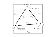
- FIG. 3 is a diagram showing the relationship between the pulse wave data f 1 , the pulse wave data f 2 and the pulse wave data f 3 in the first embodiment.
- FIG. 4 is a graph schematically showing pulse wave data f 1 and pulse wave data f 2.
- FIG. 5 is a graph schematically showing the function R 21 ( ⁇ ).
- the imaging unit 2 images a subject (measured person) and generates a moving image (step S1). Specifically, the imaging unit 2 generates a moving image of the skin exposed from the clothes of the subject. The imaging unit 2 outputs the captured moving image to the acquisition unit 31 of the processing unit 3.
- the acquisition unit 31 acquires a moving image which is information for generating pulse wave data as waveform data (step S2).
- the acquisition unit 31 outputs the acquired moving image to the waveform data generation unit 32.
- the acquisition unit 31 may store the acquired moving image in the storage unit 4.
- the waveform data generation unit 32 may access the storage unit 4 and read out the moving image stored in the storage unit 4.
- the waveform data generation unit 32 generates 3 or more waveform data (pulse wave data) from at least one moving image (step S3). Specifically, the waveform data generation unit 32 generates pulse wave data at three or more different sites of the person to be measured from the moving image.
- the waveform data generation unit 32 detects, for example, a temporal change in the color of the skin surface at each site from a moving image, and generates pulse wave data from the temporal change in the detected color.
- the waveform data generation unit 32 generates pulse wave data at three sites of the first site P1, the second site P2, and the third site P3 (see FIG. 3) will be described.
- the waveform data generation unit 32 outputs the generated pulse wave data to the calculation unit 33.
- the waveform data generation unit 32 may store the generated pulse wave data in the storage unit 4.
- the calculation unit 33 may access the storage unit 4 and read the pulse wave data stored in the storage unit 4.
- the calculation unit 33 selects two pulse wave data from three or more pulse wave data (step S4). Next, the calculation unit 33 calculates the pulse wave propagation time, which is the difference in the attribute values between the two pulse wave data selected in step S4, and the shape correlation between the two selected waveform data (step S5). ). Next, the calculation unit 33 associates the calculated pulse wave propagation time with the correlation and stores it in the storage unit 4 (step S6). That is, the calculation unit 33 correlates the pulse wave propagation time calculated from the two selected waveform data and the correlation of the shape between the two selected waveform data (pulse wave propagation time, correlation). Is stored in the storage unit 4.
- step S7 if the processing unit 3 determines that the calculation of the predetermined number of sets (pulse wave velocity, correlation) has not been completed, the process returns to step S4, and steps S4 to S6 are performed again. .. On the other hand, in step S7, when the processing unit 3 determines that the calculation of the predetermined number of sets (pulse wave velocity, correlation) has been completed, the process proceeds to step S8.
- step S4 calculation unit 33 first pulse wave data f 1 of the first portion P1, the pulse wave data f 2 of the second portion P2, and the third portion P3 of the pulse wave data f 3, selects the pulse wave data f 1 and the pulse wave data f 2 (see Figure 3).
- step S5 the calculation unit 33 determines the difference in the attribute values between the two selected pulse wave data f 1 and the pulse wave data f 2 , that is, the pulse between the first site P1 and the second site P2.
- the wave propagation time PTT 12 and the shape correlation between the pulse wave data f 1 and the pulse wave data f 2 are calculated.
- the pulse wave velocity PTT 12 between the first site P1 and the second site P2 is the time required for the pulse wave to propagate from the first site P1 to the second site P2. Therefore, the first part P1 pulse wave propagation time PTT 12 between the second portion P2, as shown in FIG. 4, one pulse wave to the corresponding pulse wave data f 1 peak and the pulse wave data f It is the time difference (time) from the peak of 2.
- the calculation unit 33 in the following manner to the first portion P1 and the pulse wave propagation time PTT 12 between the second portion P2, pulse wave data f 1 and the pulse wave data f Calculate the shape correlation between the two.
- the calculation unit 33 obtains the cross-correlation function R 12 ( ⁇ ) of the pulse wave data f 1 and the pulse wave data f 2 represented by the following equation (1).
- the calculation unit 33 calculates the lag ⁇ when the cross-correlation function R 12 ( ⁇ ) takes the maximum value R 12max as the pulse wave propagation time PTT 12 between the first site P1 and the second site P2. (See FIG. 5). Further, the calculation unit 33 calculates the maximum value R 12max as a value representing the shape correlation between the pulse wave data f 1 and the pulse wave data f 2 .
- E [X] Expected value of X
- r 1 ( ⁇ ) autocorrelation function of the pulse wave data f 1 (cross-correlation function between the pulse wave data f 1)
- r 2 ( ⁇ ) autocorrelation function of the pulse wave data f 2 (cross-correlation function between the pulse wave data f 2)
- step S6 the calculation unit 33 determines the pulse wave propagation time between the first site P1 and the second site P2 (lag ⁇ when the cross-correlation function R 12 ( ⁇ ) takes the maximum value R 12max).
- the PTT 12 is associated with the shape correlation (maximum value R 12max ) between the pulse wave data f 1 and the pulse wave data f 2 and stored in the storage unit 4.
- step S7 determines in step S7 whether or not the calculation of the pulse wave velocity and the correlation is completed. At this point, only the pulse wave propagation time PTT 12 between the first site P1 and the second site P2 and the shape correlation R 12max between the pulse wave data f 1 and the pulse wave data f 2 are completed. Therefore, it is determined as "No" in step S7, and the process returns to step S4.
- pulse wave data f 1 of the first portion P1 the pulse wave data f 2 of the second portion P2, and the third portion P3 pulse wave data f Of 3 .
- pulse wave data f 1 and pulse wave data f 3 are selected (see FIG. 3).
- the pulse wave propagation time PTT 13 between the first site P1 and the third site P3 and the pulse wave data f 1 are substantially the same as in the first step S5. and calculating a correlation shape between the pulse wave data f 3.
- the calculation unit 33 obtains the cross-correlation function R 13 ( ⁇ ) of the pulse wave data f 1 and the pulse wave data f 3.
- the calculation unit 33 calculates the lag ⁇ when the cross-correlation function R 13 ( ⁇ ) takes the maximum value R 13max as the pulse wave propagation time PTT 13 between the first site P1 and the third site P3. .
- the calculation unit 33 calculates the maximum value R 13max as a value representing the shape correlation between the pulse wave data f 1 and the pulse wave data f 3 .
- a second step S6 calculation unit 33, when the first portion P1 pulse wave propagation time between the third portion P3 (cross-correlation function R 13 where (tau) is the maximum value R 13Max
- the lag ⁇ ) PTT 13 is associated with the shape correlation (maximum value R 13max ) between the pulse wave data f 1 and the pulse wave data f 3 and stored in the storage unit 4.
- step S7 the processing unit 3 determines whether or not the calculation of the pulse wave velocity and the correlation is completed. At this point in time, and the pulse wave propagation time between the second portion P2 and the third portion P3, calculation of the correlation shape between the pulse wave data f 2 and the pulse wave data f 3 is not completed, the second In step S7 of the above, "No" is determined, and the process returns to step S4.
- step S4 the third calculation unit 33, for example, pulse wave data f 1 of the first portion P1, the pulse wave data f 2 of the second portion P2, and pulse wave data f of the third portion P3 Of 3 , pulse wave data f 2 and pulse wave data f 3 are selected (see FIG. 3).
- the pulse wave propagation time PTT 23 between the second site P2 and the third site P3 and the pulse wave data f 2 are substantially the same as in the first step S5. and calculating a correlation shape between the pulse wave data f 3.
- the calculation unit 33 obtains the cross-correlation function R 23 ( ⁇ ) of the pulse wave data f 2 and the pulse wave data f 3.
- the calculation unit 33 calculates the lag ⁇ when the cross-correlation function R 23 ( ⁇ ) takes the maximum value R 23max as the pulse wave propagation time PTT 23 between the second site P2 and the third site P3. .
- calculation unit 33 as a value representing a correlation shape between the pulse wave data f 2 and the pulse wave data f 3, it calculates the maximum value R 23max.
- the calculation unit 33 determines that the pulse wave propagation time between the second site P2 and the third site P3 (cross-correlation function R 23 ( ⁇ ) takes the maximum value R 23max ).
- the lag ⁇ ) PTT 23 is associated with the shape correlation (maximum value R 23max ) between the pulse wave data f 2 and the pulse wave data f 3 and stored in the storage unit 4.
- the processing unit 3 determines whether or not the calculation of the pulse wave velocity and the correlation is completed. At the time of the third step S7, all the pulse wave propagation times and the correlations have been calculated, so that the determination is “Yes” and the process proceeds to step S8.
- the calculation unit 33 calculates a plurality of (pulse wave propagation time, correlation) sets, and the calculated plurality of (pulse wave propagation time, correlation) sets. Is stored in the storage unit 4.
- step S8 the correction unit 34 corrects the pulse wave velocity. Specifically, first, the correction unit 34 reads out a plurality of (pulse wave velocity, correlation) sets from the storage unit 4. Next, the correction unit 34 corrects the pulse wave velocity (difference in the attribute value) based on the correlation formed with the pulse wave velocity. In particular, in the present embodiment, the correction unit 34 corrects on the basis of the pulse wave transit time PTT 12 the correlation forming the pulse wave propagation time PTT 12 a set (maximum value R 12max). Correcting unit 34 corrects on the basis of pulse wave transit time PTT 13 the correlation forming the pulse wave propagation time PTT 13 a set (maximum value R 13max). Correcting unit 34 corrects on the basis of pulse wave transit time PTT 23 the correlation forming the pulse wave propagation time PTT 23 a set (maximum value R 23max).
- the correction unit 34 corrects the pulse wave propagation time so that the lower the correlation forming the pair, the larger the correction amount with respect to the pulse wave propagation time.
- the shape correlation between the pulse wave data f 1 and the pulse wave data f 2 (maximum value R 12max ) and the shape correlation between the pulse wave data f 1 and the pulse wave data f 3 (maximum value R 13 max ). It is assumed that the shape correlation (maximum value R 23max ) between the pulse wave data f 2 and the pulse wave data f 3 is R 12max > R 13max > R 23max.
- the correction amount for the pulse wave propagation time PTT 23 corresponding to the lowest R 23max is the largest, and the correction amount for the pulse wave propagation time PTT 12 corresponding to the highest R 12max is the smallest. Correct each of PTT 12 , PTT 13 , and PTT 23.
- the (pulse wave propagation time PTT 13 , correlation R 13max ) set of pulse wave propagation time PTT 13 is the (pulse wave propagation time PTT 12 , correlation R 12max ) set of pulse wave propagation time PTT 12 and (pulse wave).
- the correction unit 34 includes a pulse wave propagation time PTT 13, the difference between the sum of the pulse wave transit time PTT 12 and the pulse wave propagation time PTT 23 (
- the specific correction method of the pulse wave velocity is not particularly limited.
- the pulse wave velocity can be corrected, for example, based on the following equation (3).
- PTT ijcalc Pulse wave velocity between the i-th part and the j-th part calculated by the calculation unit 33
- PTT incalc Pulse wave velocity between the i-th part and the nth part calculated by the calculation part 33.
- PTT njcalc Pulse wave velocity between the nth site and the jth site calculated by the calculation unit 33
- ⁇ Parameter related to the magnitude of correction amount
- R ijmax Shape correlation between pulse wave data f i at site i and pulse wave data f j at site j (maximum value of cross-correlation function R ij)
- R inmax Shape correlation between pulse wave data fi at the i- th site and pulse wave data f n at the n-th site (maximum value of cross-correlation function R in)
- R njmax (maximum value of the cross-correlation function R nj) correlation shape between the pulse wave data f n, the pulse wave data f j in the j region in the n region
- ⁇ A parameter indicating the magnitude of the contribution of the correlation to the correction amount, Is.
- the correction unit 34 may correct the pulse wave velocity based on the above equation (3) only once, or may repeat the correction of the pulse wave velocity based on the above equation (3) a plurality of times to obtain a pulse.
- the difference between the wave propagation time PTT 13 and the sum of the pulse wave propagation time PTT 12 and the pulse wave propagation time PTT 23 may be asymptotically approached.
- step S9 the correction unit 34 displays the corrected pulse wave velocity on the display unit 5 and stores it in the storage unit 4.
- the measuring device 1 is provided with an output unit such as a printer, the measuring device 1 is automatically or manually corrected after the correction of the pulse wave velocity by the correction unit 34 is completed. It may be configured so that the pulse wave velocity is output.
- the pulse wave velocity which is the difference in the attribute values, is corrected based on the correlation forming a pair with the pulse wave velocity.
- the error is smaller as the pulse wave velocity calculated using the pulse wave data having a high shape correlation. Therefore, as in the present embodiment, by correcting the pulse wave velocity based on the correlation forming a pair with the pulse wave velocity, more accurate correction becomes possible. Therefore, it is possible to measure the pulse wave velocity with high accuracy.
- the correlation of the shape between the two waveform data can be evaluated with high accuracy. Therefore, the pulse wave velocity can be measured with higher accuracy.
- the sum of the pulse wave propagation time of at least one of the selected (pulse wave velocity, correlation) set and the pulse wave propagation time of the remaining (pulse wave propagation time, correlation) set is selected.
- Select a (pulse wave velocity, correlation) set that can correspond to, and add the sum of at least one pulse wave propagation time of the selected (pulse wave velocity, correlation) set and the remaining (pulse wave velocity, correlation).
- Wave propagation time, correlation The pulse wave propagation time is repeatedly corrected so that the difference from the sum of the pulse wave propagation times of the set becomes small. Therefore, the pulse wave velocity can be measured with higher accuracy.
- a plurality of waveform data are generated from one image (moving image). Therefore, for example, it is not necessary to attach a detector to each of a plurality of parts of the person to be measured, and a plurality of waveform data can be generated by one imaging. Therefore, a plurality of waveform data can be easily generated, and as a result, the pulse wave velocity can be easily measured. Also, unlike the case where a detector is attached to each part of the person to be measured and the waveform data of each part is acquired, when a plurality of waveform data are acquired by capturing one image, the number of waveform data to be acquired. Can be easily increased. That is, a lot of waveform data can be easily acquired. By calculating the pulse wave velocity from more waveform data, the measurement accuracy of the pulse wave velocity can be improved. Therefore, by generating a plurality of waveform data from one image, it is possible to measure the pulse wave velocity with higher accuracy.
- the image can be captured by non-contact. Therefore, by generating the waveform data from the image, the pulse wave velocity can be easily measured without attaching a detector or the like to the person to be measured.
- FIGS. 1 to 3 are commonly referred to.
- pulse wave data at each of the first site P1, the second site P2, and the third site P3 are acquired, and the pulse wave propagation time is calculated and the pulse wave propagation time is calculated using the three pulse wave data.
- An example of performing correction has been described.
- the present invention is not limited to this.
- steps S4 to S6 are performed twice.
- the waveform data generation unit 32 selects two pulse wave data f 1 and pulse wave data f 2.
- the calculation unit 33 determines the difference in the attribute values between the two selected pulse wave data f 1 and the pulse wave data f 2 , that is, the difference between the first site P1 and the second site P2.
- the pulse wave propagation time PTT 12 between them and the shape correlation R 12max between the pulse wave data f 1 and the pulse wave data f 2 are calculated.
- the waveform data generation unit 32 selects two pulse wave data f 2 and pulse wave data f 3.
- the calculation unit 33 determines the difference in the attribute values between the two selected pulse wave data f 2 and the pulse wave data f 3 , that is, the difference between the second site P2 and the third site P3.
- the pulse wave propagation time PTT 23 between them and the shape correlation R 23max between the pulse wave data f 2 and the pulse wave data f 3 are calculated.
- step S8 the correction unit 34 corrects the pulse wave propagation time PTT 12 and the pulse wave propagation time PTT 23 based on the correlation R 12max and the correlation R 23max . Specifically, the correction unit 34 increases the correction amount of the pulse wave propagation time PTT 12 and the pulse wave propagation time PTT 23 , whichever has the lower correlation, and decreases the correction amount of the one with the higher correlation. The propagation time PTT 12 and the pulse wave propagation time PTT 23 are corrected.
- the correction unit 34 calculates the distance between the first part P1 and the second part P2 and the distance between the second part P2 and the third part P3, and uses these distances for the pulse wave velocity.
- the pulse wave velocity may be calculated from each of the PTT 12 and the pulse wave propagation time PTT 23. Since these pulse wave velocities can be directly compared, each pulse wave velocity is corrected based on the correlation R 12max and the correlation R 23max , and then the pulse wave velocity and the corrected pulse wave velocity and the distance are used to correct the pulse wave velocity.
- the time may be calculated. By doing so, it becomes possible to calculate the pulse wave velocity with higher accuracy.
- the pulse wave velocity may be corrected based on two (pulse wave velocity, correlation) pairs. Even in this case, since the pulse wave velocity is calculated based on the correlation, the pulse wave velocity can be calculated with high accuracy.
- the measuring device according to the third embodiment has substantially the same configuration as the measuring device 1 according to the first embodiment except for the operation of the correction unit 34.
- the correction unit 34 selects a part of a plurality of (pulse wave velocity, correlation) sets calculated by the calculation unit 33.
- the correction unit 34 corrects the pulse wave propagation time (difference in attribute values) of the selected (pulse wave propagation time, correlation) set based on the correlation forming a pair with the pulse wave propagation time.
- the correction unit 34 first reads the threshold value stored in the storage unit 4. This threshold is the threshold of the correlation with respect to the shape of the waveform data. Next, the correction unit 34 excludes the (pulse wave velocity, correlation) set whose correlation is less than the threshold value, and selects the (pulse wave propagation time, correlation) set whose correlation is equal to or higher than the threshold value. The correction unit 34 corrects the pulse wave propagation time (difference in attribute values) of the selected (pulse wave propagation time, correlation) set based on the correlation forming a pair with the pulse wave propagation time.
- the waveform data generation unit 32 shown in FIG. 1 has a pulse in each of the first part P1, the second part P2, the third part P3, the fourth part P4, and the fifth part P5.
- Wave data f 1 (t), f 2 (t), f 3 (t), f 4 (t), f 5 (t) are generated.
- the calculation unit 33 sets the (pulse wave propagation time PTT 12 , correlation R 12max ) set and (pulse wave propagation time PTT 13 , correlation R 13max ) set shown in FIG. , (Pulse wave propagation time PTT 14 , correlation R 14max ), (Pulse wave propagation time PTT 15 , correlation R 15max ), (Pulse wave propagation time PTT 23 , correlation R 23max ), (Pulse wave propagation time PTT 24) , Correlation R 24max ), (Pulse wave propagation time PTT 25 , Correlation R 25max ), (Pulse wave propagation time PTT 34 , Correlation R 34max ), (Pulse wave propagation time PTT 35 , Correlation R 35max ), and , (Pulse wave propagation time PTT 45 , correlation R 45max ) is calculated and stored in the storage unit 4.
- the correction unit 34 reads out the threshold value stored in the storage unit 4.
- the correction unit 34 includes (pulse wave propagation time PTT 12 , correlation R 12max ) set, (pulse wave propagation time PTT 13 , correlation R 13max ) set, (pulse wave propagation time PTT 14 , correlation R 14max ) set, (Pulse wave propagation time PTT 15 , correlation R 15max ) set, (Pulse wave propagation time PTT 23 , correlation R 23max ) set, (Pulse wave propagation time PTT 24 , correlation R 24max ) set, (Pulse wave propagation time PTT 25 , Correlation R 25max ), (Pulse wave propagation time PTT 34 , Correlation R 34max ), (Pulse wave propagation time PTT 35 , Correlation R 35max ), and (Pulse wave propagation time PTT 45 , Correlation R 45max ) Of these, those whose correlation is
- the correction unit 34 selects at least a part of the sets not excluded (pulse wave velocity, correlation). Specifically, the correction unit 34 includes a part of (pulse wave propagation time, correlation) set, that is, (pulse wave propagation time PTT 13 , correlation R 13max ) set, (pulse wave propagation time PTT 15 , correlation R 15max). ) Group, (Pulse wave propagation time PTT 34 , Correlation R 34max ) group, (Pulse wave propagation time PTT 45 , Correlation R 45max ) group are selected.
- the correction unit 34 corrects the selected pulse wave velocity PTT 13 , PTT 15 , PTT 34 , and PTT 45 based on the correlations R 13max, R 15max , R 34max , and R 45max that form a pair with the pulse wave velocity. ..
- the pulse wave velocity can be more preferably corrected.
- PTT ijcalc Pulse wave velocity between the i-th site and the j-th site calculated by the calculation unit 33
- PTT incal Pulse wave velocity between the i-th site and the n-th site calculated by the calculation unit 33
- PTT njcalc Pulse wave velocity between the nth site and the jth site calculated by the calculation unit 33
- PTT nmcalc Pulse wave velocity between the nth site and the mth site calculated by the calculation unit 33
- PTT mjcalc Pulse wave velocity between the m-th site and the j-th site calculated by the calculation unit 33
- R ijmax Shape correlation between pulse wave data f i at site i and pulse wave data f j at site j (maximum value of cross-correlation function R ij), R inmax : Shape correlation between pulse wave data fi at the i- th site and pulse wave data f n at the n
- the pulse wave propagation time is made higher by correcting the pulse wave propagation time of a part of the plurality of (pulse wave propagation time, correlation) sets calculated by the calculation unit 33.
- some (pulse wave propagation time, correlation) sets having a high correlation are selected and selected ().
- the pulse wave propagation time can be measured with higher accuracy by correcting the pulse wave propagation time of the (pulse wave propagation time, correlation) set.
- the measuring device does not have an imaging unit, acquires an image (for example, a moving image) from an external device directly connected or wirelessly connected, and obtains a plurality of pulse wave data from the acquired moving image. It may be the one to be generated. In that case, it is preferable that the measuring device includes an acquisition unit that acquires information for generating pulse wave data from an external device.
- the measuring device may include a detector that directly acquires the waveform.
- the detector include a pressure sensor that detects a pressure change, an optical sensor that detects light intensity, a microphone that collects sound, an ultrasonic sensor that detects ultrasonic waves, and a displacement sensor that detects displacement of a seismograph or the like. And so on.
- the measuring device may include a plurality of detectors for detecting pulse waves at the site where each is installed. If the measuring device has a detection unit that directly detects the pulse wave, or if the pulse wave is directly input from the detector or the like, the measuring device has an imaging unit 2, an acquisition unit 31, and a waveform data generation unit. It is not always necessary to provide 32.
- the method of calculating the difference between the attribute values and the correlation is not particularly limited.
- the difference and the correlation of the attribute values may be obtained by using the mutual covariance function shown in the following equation (5).
- c ij ( ⁇ ) the pulse wave data f i in the i region, cross-covariance function of the pulse wave data f j in the j region
- V Dispersion
- ⁇ average
- the pulse wave propagation time between the i-th site and the j-th site is given as the lag ⁇ when the mutual covariance function C ij ( ⁇ ) takes the maximum value, and is the maximum of the mutual covariance function C ij ( ⁇ ).
- a pulse wave data f i value C ijmax is in the i region is given as a function of the pulse wave data f j in the j region.
- the method of selecting a part (pulse wave velocity, correlation) from a plurality of (pulse wave velocity, correlation) pairs is not particularly limited.
- a set (pulse wave velocity, correlation) calculated from pulse wave data whose quality satisfies a setting criterion (predetermined quality) may be selected.
- the quality setting standard can be appropriately set according to parameters such as the amplitude of the pulse wave data, the data length of the pulse wave data, and the S / N ratio of the pulse wave data.
- the maximum value R max is used as the correlation between the shapes of the two waveform data, and in the above modified example, the maximum value Cijmax is used.
- the correlation between the shapes of the two waveform data is not limited to the above maximum value.
- the correlation between the shapes of the two waveform data may be used as an index showing the degree of deviation of the shape between the two waveform data such as the mean square error between the two waveform data and the Euclidean distance. In this case, it is preferable that the higher the degree of deviation, the larger the correction amount of the difference in the attribute values, and the lower the degree of deviation, the smaller the correction amount of the difference in the attribute values.
- the waveform data is pulse wave data, which is waveform data representing a time change of an observed value at an arbitrary point. That is, an example in which the attribute value is time has been described.
- the waveform data is not limited to the waveform data whose attribute value is the time.
- the waveform data may be, for example, waveform data whose attribute value is a position.
- the waveform data may be, for example, waveform data representing the spatial distribution of observed values at an arbitrary time.
- the difference in attribute values may be calculated as a phase difference.
- the present invention is not limited to this configuration.
- the measuring device according to the present invention may not include, for example, a display unit.
Landscapes
- Health & Medical Sciences (AREA)
- Life Sciences & Earth Sciences (AREA)
- Engineering & Computer Science (AREA)
- Public Health (AREA)
- Molecular Biology (AREA)
- Cardiology (AREA)
- Veterinary Medicine (AREA)
- Physics & Mathematics (AREA)
- General Health & Medical Sciences (AREA)
- Biophysics (AREA)
- Pathology (AREA)
- Biomedical Technology (AREA)
- Heart & Thoracic Surgery (AREA)
- Medical Informatics (AREA)
- Physiology (AREA)
- Surgery (AREA)
- Animal Behavior & Ethology (AREA)
- Signal Processing (AREA)
- Computer Vision & Pattern Recognition (AREA)
- Artificial Intelligence (AREA)
- Psychiatry (AREA)
- Vascular Medicine (AREA)
- Measuring Pulse, Heart Rate, Blood Pressure Or Blood Flow (AREA)
- Measuring And Recording Apparatus For Diagnosis (AREA)
Priority Applications (3)
| Application Number | Priority Date | Filing Date | Title |
|---|---|---|---|
| CN202080060026.9A CN114302674B (zh) | 2019-09-06 | 2020-06-26 | 测量装置及测量方法 |
| US17/634,384 US20220323015A1 (en) | 2019-09-06 | 2020-06-26 | Measurement apparatus and measurement method |
| JP2021543968A JP7133102B6 (ja) | 2019-09-06 | 2020-06-26 | 測定装置及び測定方法 |
Applications Claiming Priority (2)
| Application Number | Priority Date | Filing Date | Title |
|---|---|---|---|
| JP2019-162539 | 2019-09-06 | ||
| JP2019162539 | 2019-09-06 |
Publications (1)
| Publication Number | Publication Date |
|---|---|
| WO2021044712A1 true WO2021044712A1 (ja) | 2021-03-11 |
Family
ID=74853173
Family Applications (1)
| Application Number | Title | Priority Date | Filing Date |
|---|---|---|---|
| PCT/JP2020/025114 Ceased WO2021044712A1 (ja) | 2019-09-06 | 2020-06-26 | 測定装置及び測定方法 |
Country Status (4)
| Country | Link |
|---|---|
| US (1) | US20220323015A1 (https=) |
| JP (1) | JP7133102B6 (https=) |
| CN (1) | CN114302674B (https=) |
| WO (1) | WO2021044712A1 (https=) |
Families Citing this family (1)
| Publication number | Priority date | Publication date | Assignee | Title |
|---|---|---|---|---|
| CN118436324B (zh) * | 2023-09-07 | 2025-01-10 | 荣耀终端有限公司 | 脉搏到达时间差获取方法、中心血压获取方法及装置 |
Citations (3)
| Publication number | Priority date | Publication date | Assignee | Title |
|---|---|---|---|---|
| WO2008135892A2 (en) * | 2007-05-02 | 2008-11-13 | Philips Intellectual Property & Standards Gmbh | Apparatus for performing pulse wave velocity measurements |
| WO2019116996A1 (ja) * | 2017-12-15 | 2019-06-20 | シャープ株式会社 | 血圧測定装置、および、血圧測定方法 |
| JP2019110987A (ja) * | 2017-12-21 | 2019-07-11 | オムロンヘルスケア株式会社 | 測定装置およびプログラム |
Family Cites Families (11)
| Publication number | Priority date | Publication date | Assignee | Title |
|---|---|---|---|---|
| US7395967B2 (en) * | 2005-07-21 | 2008-07-08 | University Of Washington | Methods and systems for counterbalancing a scanning beam device |
| JP2007241958A (ja) * | 2006-03-13 | 2007-09-20 | Nec Corp | 証拠資料作成支援装置、証拠資料作成支援方法、及び証拠資料作成支援プログラム |
| US7912278B2 (en) * | 2006-05-03 | 2011-03-22 | Siemens Medical Solutions Usa, Inc. | Using candidates correlation information during computer aided diagnosis |
| JP4789203B2 (ja) * | 2006-10-02 | 2011-10-12 | フクダ電子株式会社 | 血圧反射機能測定装置 |
| KR101150791B1 (ko) * | 2007-09-11 | 2012-06-13 | 도쿄엘렉트론가부시키가이샤 | 정보 처리 장치, 정보 처리 방법 및, 프로그램이 기록된 컴퓨터 판독가능 기록매체 |
| WO2015162719A1 (ja) * | 2014-04-23 | 2015-10-29 | 楽天株式会社 | 情報提供装置、情報提供方法、プログラム、及び記録媒体 |
| US10744261B2 (en) * | 2015-09-25 | 2020-08-18 | Sanmina Corporation | System and method of a biosensor for detection of vasodilation |
| JP6531834B2 (ja) * | 2015-11-20 | 2019-06-19 | 富士通株式会社 | 情報処理装置、情報処理方法、および情報処理プログラム |
| US10215619B1 (en) * | 2016-09-06 | 2019-02-26 | PhysioWave, Inc. | Scale-based time synchrony |
| JP7044171B2 (ja) * | 2018-10-02 | 2022-03-30 | 富士通株式会社 | 脈波算出装置、脈波算出方法及び脈波算出プログラム |
| CN109864724B (zh) * | 2019-04-04 | 2022-02-01 | 复旦大学附属中山医院 | 一种新型基于ecg和ppg血压变化计算系统 |
-
2020
- 2020-06-26 CN CN202080060026.9A patent/CN114302674B/zh active Active
- 2020-06-26 JP JP2021543968A patent/JP7133102B6/ja active Active
- 2020-06-26 WO PCT/JP2020/025114 patent/WO2021044712A1/ja not_active Ceased
- 2020-06-26 US US17/634,384 patent/US20220323015A1/en not_active Abandoned
Patent Citations (3)
| Publication number | Priority date | Publication date | Assignee | Title |
|---|---|---|---|---|
| WO2008135892A2 (en) * | 2007-05-02 | 2008-11-13 | Philips Intellectual Property & Standards Gmbh | Apparatus for performing pulse wave velocity measurements |
| WO2019116996A1 (ja) * | 2017-12-15 | 2019-06-20 | シャープ株式会社 | 血圧測定装置、および、血圧測定方法 |
| JP2019110987A (ja) * | 2017-12-21 | 2019-07-11 | オムロンヘルスケア株式会社 | 測定装置およびプログラム |
Also Published As
| Publication number | Publication date |
|---|---|
| US20220323015A1 (en) | 2022-10-13 |
| CN114302674A (zh) | 2022-04-08 |
| CN114302674B (zh) | 2024-07-09 |
| JP7133102B6 (ja) | 2024-02-02 |
| JPWO2021044712A1 (https=) | 2021-03-11 |
| JP7133102B2 (ja) | 2022-09-07 |
Similar Documents
| Publication | Publication Date | Title |
|---|---|---|
| US8197408B2 (en) | Sparse tissue property measurements in medical ultrasound imaging | |
| US8394024B2 (en) | Ultrasound diagnostic apparatus and method for tracing movement of tissue | |
| US20110231160A1 (en) | Subject information processing apparatus, subject information processing method, and subject information processing program | |
| KR101132536B1 (ko) | 영상 정합을 수행하는 시스템 및 방법 | |
| CN115715170A (zh) | 用于估计血液动力学参数的方法 | |
| KR20170085516A (ko) | 전단파 탄성초음파 영상화를 수행하기 위한 영상화 방법 및 장치 | |
| EP4625350A3 (en) | USE OF A SET OF MACHINE LEARNING DIAGNOSTIC MODELS TO DETERMINE A DIAGNOSIS BASED ON A PATIENT'S COMPLEXION | |
| CN102695457A (zh) | 超声波诊断装置及测量内中膜的厚度的方法 | |
| CN105997150B (zh) | 负荷超声心动图中的自适应定时引导 | |
| JP2020528304A5 (https=) | ||
| CN103124521A (zh) | 超声波图像生成装置、超声波图像生成方法、以及程序 | |
| CN103298413A (zh) | 超声波诊断装置以及利用该超声波诊断装置的超声波测量方法 | |
| CN106102586A (zh) | 超声波诊断装置 | |
| JP7133102B2 (ja) | 測定装置及び測定方法 | |
| KR20170083507A (ko) | 음향 방사력 임펄스 이미징에서의 모션 독립 | |
| KR102135153B1 (ko) | 초음파 영상 장치 및 그 영상 표시 방법 | |
| US20130158403A1 (en) | Method for Obtaining a Three-Dimensional Velocity Measurement of a Tissue | |
| JP4492107B2 (ja) | 画像診断装置 | |
| JP2014233521A (ja) | 血管径測定装置および血管径測定方法 | |
| CN106170254B (zh) | 超声波观测装置 | |
| JP2019107421A (ja) | 光音響装置および被検体情報取得方法 | |
| JPWO2021044712A5 (https=) | ||
| US10925494B2 (en) | Optical sensor-based blood pressure measuring device | |
| EP4248880B1 (en) | Image processing device and method for controlling image processing device | |
| CN107260155A (zh) | 检测血液流速的方法及其装置 |
Legal Events
| Date | Code | Title | Description |
|---|---|---|---|
| 121 | Ep: the epo has been informed by wipo that ep was designated in this application |
Ref document number: 20861152 Country of ref document: EP Kind code of ref document: A1 |
|
| ENP | Entry into the national phase |
Ref document number: 2021543968 Country of ref document: JP Kind code of ref document: A |
|
| NENP | Non-entry into the national phase |
Ref country code: DE |
|
| 122 | Ep: pct application non-entry in european phase |
Ref document number: 20861152 Country of ref document: EP Kind code of ref document: A1 |