WO2021040049A1 - 送信器、受信器、及び通信システム - Google Patents
送信器、受信器、及び通信システム Download PDFInfo
- Publication number
- WO2021040049A1 WO2021040049A1 PCT/JP2020/032955 JP2020032955W WO2021040049A1 WO 2021040049 A1 WO2021040049 A1 WO 2021040049A1 JP 2020032955 W JP2020032955 W JP 2020032955W WO 2021040049 A1 WO2021040049 A1 WO 2021040049A1
- Authority
- WO
- WIPO (PCT)
- Prior art keywords
- transmitter
- converter
- cable
- substrate
- signal
- Prior art date
Links
Images


Classifications
-
- H—ELECTRICITY
- H04—ELECTRIC COMMUNICATION TECHNIQUE
- H04B—TRANSMISSION
- H04B10/00—Transmission systems employing electromagnetic waves other than radio-waves, e.g. infrared, visible or ultraviolet light, or employing corpuscular radiation, e.g. quantum communication
- H04B10/25—Arrangements specific to fibre transmission
-
- H—ELECTRICITY
- H04—ELECTRIC COMMUNICATION TECHNIQUE
- H04B—TRANSMISSION
- H04B10/00—Transmission systems employing electromagnetic waves other than radio-waves, e.g. infrared, visible or ultraviolet light, or employing corpuscular radiation, e.g. quantum communication
- H04B10/50—Transmitters
-
- G—PHYSICS
- G02—OPTICS
- G02B—OPTICAL ELEMENTS, SYSTEMS OR APPARATUS
- G02B6/00—Light guides; Structural details of arrangements comprising light guides and other optical elements, e.g. couplings
- G02B6/24—Coupling light guides
- G02B6/42—Coupling light guides with opto-electronic elements
- G02B6/4292—Coupling light guides with opto-electronic elements the light guide being disconnectable from the opto-electronic element, e.g. mutually self aligning arrangements
-
- H—ELECTRICITY
- H04—ELECTRIC COMMUNICATION TECHNIQUE
- H04B—TRANSMISSION
- H04B10/00—Transmission systems employing electromagnetic waves other than radio-waves, e.g. infrared, visible or ultraviolet light, or employing corpuscular radiation, e.g. quantum communication
- H04B10/60—Receivers
- H04B10/66—Non-coherent receivers, e.g. using direct detection
- H04B10/69—Electrical arrangements in the receiver
-
- H—ELECTRICITY
- H04—ELECTRIC COMMUNICATION TECHNIQUE
- H04B—TRANSMISSION
- H04B10/00—Transmission systems employing electromagnetic waves other than radio-waves, e.g. infrared, visible or ultraviolet light, or employing corpuscular radiation, e.g. quantum communication
- H04B10/80—Optical aspects relating to the use of optical transmission for specific applications, not provided for in groups H04B10/03 - H04B10/70, e.g. optical power feeding or optical transmission through water
Definitions
- the present invention relates to a transmitter that transmits an optical signal, a receiver that receives an optical signal, and a communication system that transmits and receives an optical signal.
- inter-device communication has been performed by transmitting and receiving electrical signals using a metal cable as a transmission medium.
- USB Universal Serial Bus
- HDMI High-definition Digital Media Interface, registered trademarks
- AOC Active Optical Cable
- the AOC is provided at (1) an optical cable, (2) a first connector provided at one end of the optical cable and having an E / O converter built-in, and (3) an O / E converter provided at the other end of the optical cable. It is composed of a second connector with a built-in and.
- the electric signal output from the transmitting device (for example, a camera) is converted into an optical signal by the E / O converter of the first connector connected to the transmitting device, and is transmitted through the optical cable.
- the optical signal transmitted through the optical cable is converted into an electric signal by the O / E converter of the second connector connected to the device on the receiving side (for example, a grabber) and input to the device on the receiving side.
- Examples of documents that disclose AOC include Patent Document 1.
- Japanese Patent Publication Japanese Patent Laid-Open No. 2012-60522
- One aspect of the present invention has been made in view of the above problems, and realizes a transmitter that is easy to miniaturize or simplify, realizes a receiver that is easy to miniaturize or simplify, or ,
- the purpose is to realize a communication system in which the transmitter and the receiver can be easily miniaturized or simplified.
- the first substrate, the signal source mounted on the first substrate, the second substrate different from the first substrate, and the second substrate An E / O converter mounted on the above, which transmits an E / O converter that converts an electric signal output from the signal source into an optical signal and an optical signal output from the E / O converter.
- An optical cable and an optical connector provided at the end of the optical cable are provided, and the electric signal input to the E / O converter is the electric signal itself output from the signal source. It has been adopted.
- the receiver according to one aspect of the present invention is a receiver that receives an optical signal transmitted from the transmitter according to one aspect of the present invention, and is an O / E converter that converts the optical signal into an electric signal.
- a configuration is adopted in which an electric signal output from the O / E converter is processed as an electric signal output from the signal source, and a receiving circuit is provided.
- a configuration is adopted in which a transmitter according to one aspect of the present invention and a receiver according to one aspect of the present invention are included.
- a transmitter that can be easily miniaturized or simplified.
- a receiver that can be easily miniaturized or simplified.
- FIG. 1A is a side view showing the configuration of the transmitter shown in FIG. (B) is a plan view of the first substrate included in the transmitter shown in (a), and (c) is a plan view of the second substrate included in the transmitter shown in (a).
- It is a block diagram which shows the 4th modification of the transmitter shown in FIG.
- It is a top view which shows the 5th modification of the transmitter shown in FIG.
- It is a top view which shows the 6th modification of the transmitter shown in FIG.
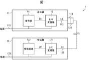
- FIG. 1 is a block diagram showing a configuration of communication system 1.
- the communication system 1 includes a transmitter 11 that transmits an optical signal LS and a receiver 12 that receives an optical signal LS.
- the transmitter 11 transmits a signal source 111 that outputs an electric signal ES, an E / O converter 112 that converts the electric signal ES into an optical signal LS, and an optical signal LS output from the E / O converter 112. It includes an optical cable 113. Further, the receiver 12 outputs the O / E converter 121 that converts the optical signal LS into the electric signal ES'and the electric signal ES' that is output from the O / E converter 121 from the signal source 111. It includes a receiving circuit 122 that processes as a signal ES, and an optical cable 123 that transmits an optical signal LS input to the O / E converter 121.
- the communication system 1, the transmitter 11, and the receiver 12 capable of transmitting the electric signal ES output from the signal source 111 over a long distance at high speed.
- the same effect as monitoring the electrical signal ES output from the signal source 111 in real time with a device that is separated from the signal source 111 and is electrically connected to the receiver 12. Is obtained.
- the electric signal ES output from the signal source 111 is input to the E / O converter 112 without going through a general-purpose communication interface (USB interface, HDMI, etc.), either the transmitter 11 side or the receiver 12 side It is not necessary to provide a general-purpose communication interface in one or both. Therefore, it is easy to realize miniaturization or simplification in either one or both of the transmitter 11 and the receiver 12.
- the signal source 111 is an image sensor
- the electric signal ES is an image signal output from this image sensor.
- the receiving circuit 122 processes the electric signal ES'output from the O / E converter 121 as an image signal output from the image sensor. Therefore, it is possible to realize the communication system 1, the transmitter 11, and the receiver 12 capable of transmitting the electric signal output from the image sensor over a long distance at high speed. In other words, the image signal output from the image sensor can be monitored in real time in the vicinity of the receiver 12 away from the image sensor.
- Examples of the image signal output from the image sensor include an image signal compliant with SLVS-EC (Scalable Low Voltage Signaling Embedded Clock) or MIPI (Mobile Industry Processor Interface, registered trademark).
- SLVS-EC and MIPI are communication standards dedicated to image transmission, and are not general-purpose communication standards such as USB and HDMI.
- the clock is included in the data string. Therefore, the SLVS-EC compliant image signal has an advantage that there is no problem of skew (variation in delay time). Further, since the image signal conforming to SLVS-EC is DC-balanced, it is suitable for optical communication between devices.
- MIPI is a widely used standard.
- the transmitter 11 can be connected to many types of MIPI compliant devices, and many types of MIPI compliant devices will be described later as receivers. It can be connected to 12. That is, the MIPI-compliant image signal is suitable for inter-device communication between many types of devices.
- the transmitter 11 further includes an optical connector 114 provided at the end of the optical cable 113.
- the optical cable 113 is an optical cable that connects the E / O converter 112 and the optical connector 114.
- the transmitter 11 may further include a case for accommodating at least the signal source 111 and the E / O converter 112.
- the optical connector 114 may be provided at the end of the case of the transmitter 11, or may be provided at a distance from the end of the case of the transmitter 11.
- the receiver 12 further includes an optical connector 124 provided at the end of the optical cable 123.
- the optical cable 123 is an optical cable that connects the O / E converter 121 and the optical connector 124.
- the receiver 12 may further include a case for accommodating at least the receiving circuit 122 and the O / E converter 121.
- the optical cable 123 is pulled out from the end of the case of the receiver 12 and extends to the outside of the receiver 12.
- the optical connector 124 may be provided at the end of the case of the receiver 12, or may be provided at a distance from the end of the case of the receiver 12.
- the transmitter 11 when the transmitter 11 (including the optical cable 113) has a problem, the transmitter 11 can be replaced without modifying the receiver 12 (including the optical cable 123). .. Similarly, in the communication system 1, when a problem occurs in the receiver 12 (including the optical cable 123), the receiver 12 can be replaced without modifying the transmitter 11 (including the optical cable 113). .. That is, in the communication system 1, it is easy to deal with a problem in one or both of the transmitter 11 and the receiver 12. Further, in the communication system 1, it is assumed that the optical cable 113 or the optical cable 123 is used in a fixed state. An example of a fixed mode of the optical cable 113 or the optical cable 123 is burying in the ground.
- the receiver 12 or the optical cable 123 is not significantly modified.
- the vessel 11 can be replaced.
- the communication system 1 including the signal source 111 which is an image sensor can be said to be one aspect of the video system. In such a video system, it is mainly the signal source 111 included in the transmitter 11 that determines the performance. For example, when the user wants to upgrade the resolution of the signal source 111 or replace the signal source 111 with an image sensor corresponding to the infrared region, in the communication system 1, the receiver 12 or the optical cable 123 is used.
- the transmitter 11 can be upgraded or replaced without major modification.
- the receiver 12 when the signal source 111 is used as an image sensor of a surveillance camera, the receiver 12 is often arranged in a place invisible to human eyes (for example, indoors such as a surveillance room or a control room).
- the transmitter 11 is often arranged in a place where people can see it (outdoors where there are people and cars). Therefore, the transmitter 11 tends to have a higher failure frequency than the receiver 12.
- the communication system 1 in which the transmitter 11 can be exchanged without significantly modifying the receiver 12 or the optical cable 123 is a rational communication system.
- the transmitter 11 or the optical cable 113 is significantly modified.
- the receiver 12 can be replaced without.
- the optical cable 113 is housed in the optical connector 114 and the case, so that an external force is applied. It is possible to suppress the malfunction of the optical cable 113 due to the above.
- the optical cable 123 is housed in the optical connector 124 and the case, so that an external force or the like is generated. It is possible to suppress the malfunction of the optical cable 123 due to the above.
- the optical connector 114 and the optical connector 124 may be indirectly connected by using an optical cable separate from the optical cable 113 and the optical cable 123, and the optical connector 114 and the optical connector may be connected to each other indirectly. It may be directly connected to 124.
- the optical cable connecting the optical connector 114 and the optical connector 124 is fixed, a problem occurs in either or both of the transmitter 11 and the receiver 12. However, the defective device can be easily replaced.
- general-purpose communication interfaces tend to generate heat as they operate. Therefore, in one or both of the transmitter and the receiver provided with the general-purpose communication interface, the size tends to be relatively large in consideration of heat generation by the general-purpose communication interface. Therefore, it is difficult to miniaturize one or both of the transmitter and the receiver. On the other hand, since it is not necessary to provide a general-purpose communication interface for either or both of the transmitter 11 and the receiver 12, as described above, it is not necessary to consider heat generation due to the general-purpose communication interface. Therefore, further miniaturization is possible.
- n is an arbitrary natural number of 1 or more.
- n-core optical cables are used as the optical cables 113 and 123.
- MPO Multi-fiber Push On
- the number of cores of the MPO is not limited and can be appropriately selected. Examples of the number of cores of the widely used MPO are 12 cores and 24 cores.
- the transmitter 11 is a metal cable 115 that transmits at least the electric power supplied to the signal source 111, and further includes a metal cable 115 that is independent of the optical cable 113. Therefore, in the communication system 1, power can be supplied to the signal source 111 from the power source arranged in the vicinity of the transmitter 11.
- This power supply is an example of a transmission side power supply, and is for supplying power to the signal source 111.
- the metal cable 115 may be configured to power only the signal source 111, or may be configured to power the signal source 111 and the E / O converter 112. It may be configured to supply power only to the E / O converter 112.
- the metal cable 115 may be electrically connected only to the signal source 111, may be electrically connected to the signal source 111 and the E / O converter 112, or may be electrically connected to the E / O converter 112. It may be electrically connected only to 112.
- the electric power transmitted by the metal cable 115 is supplied to the E / O converter 112 in addition to the signal source 111.
- the structure of the cable connected to the E / O converter 112 can be simplified as compared with the case where the composite cable is used as the cable connected to the E / O converter 112.
- the cost can be reduced.
- the transmission distance in the communication system 1 can be increased.
- the cable can be made smaller and / or lighter in size, or both.
- the problem of voltage drop can be suppressed.
- the transmitter 11 includes a control unit such as a microcomputer, the electric power transmitted by the metal cable 115 may be supplied to the control unit.
- the metal cable 115 and the E / O converter 112 are electrically connected to each other, but may not be electrically connected to each other.
- the metal cable 115 is electrically connected to the signal source 111 and the E / O converter 112.
- the metal cable 115 is a metal for connecting a transmitting side power supply that can be connected to a transmitting side power supply when it is arranged outside the transmitter 11 and can supply power from the transmitting side power supply to the signal source 111 and the E / O converter 112. This is an example of a cable.
- the metal cable 115 is pulled out from the case of the transmitter 11 so that it can be connected to the power supply on the transmitting side. Therefore, the metal cable 115 can be wired independently of the optical cable 113 and the optical cable 123.
- the metal cable 115 can determine the wiring path regardless of the wiring path of the optical cable 113 and the optical cable 123. As a result, it is not necessary to supply power from the receiver 12 to the signal source 111 and the E / O converter 112 of the transmitter 11, so that the optical cable 113 and the metal cable are as shown in the first modification (see FIG. 3). It is no longer necessary to use the composite cable 116 including the 115. Therefore, when the transmitter 11 and the receiver 12 are connected by a cable as compared with the first modification, the outer diameter of the cable can be reduced.
- the receiver 12 includes a metal cable 125 for transmitting the electric power supplied to the receiving circuit 122. Therefore, in the communication system 1, power can be supplied to the receiving circuit 122 from the power source arranged in the vicinity of the receiver 12.
- the electric power transmitted by the metal cable 125 is supplied to the O / E converter 121 in addition to the receiving circuit 122.
- the receiver 12 includes a control unit such as a microcomputer, the electric power transmitted by the metal cable 125 may be supplied to this control unit.
- the metal cable 125 and the O / E converter 121 are electrically connected to each other, but may not be electrically connected to each other.
- one end of the metal cable 125 is electrically connected to the O / E converter 121 and the receiving circuit 122.
- the metal cable 125 is for connecting the receiving side power supply which can be connected to the receiving side power supply when it is arranged outside the receiver 12 and can supply power to the O / E converter 121 and the receiving circuit 122 from the receiving side power supply.
- This is an example of a metal cable.
- the metal cable 125 is pulled out from the case of the receiver 12 so that it can be connected to the power supply on the receiving side. As a result, when the transmitter 11 and the receiver 12 are connected by a cable, the outer diameter of the cable can be reduced as in the case of the transmitter 11.
- the transmitter 11 further includes the metal cable 115, soldering can be used when the end of the metal cable 115 is electrically connected to the second substrate 110b. Therefore, the metal cable 115 can be connected to the second substrate 110b by using a simple structure as compared with the case of using the connector. That is, the manufacturing cost of the transmitter 11 can be reduced. Therefore, a configuration in which the metal cable 115 and the substrate 110 are connected via solder can be realized. Further, the connection using soldering has higher reliability than the connection using, for example, a connector. Further, the same effect can be obtained by further providing the receiver 12 with the metal cable 125.
- the signal source 111 is an image sensor, but the present invention is not limited to this. That is, the signal source 111 can be any device that outputs an electrical signal.
- a sensor such as an image sensor, a color sensor, a brightness sensor, a wavelength sensor, a temperature sensor, a vibration sensor, or a distortion sensor, or a processor such as a CPU (Central Processing Unit) is an example of a device that can be used as a signal source 111. ..
- CPU Central Processing Unit
- the electric signal input to the E / O converter 112 is the electric signal ES itself output from the signal source 111, but the present invention is not limited to this. That is, the electric signal input to the E / O converter 112 may be an electric signal obtained by processing the electric signal ES output from the signal source 111 by a signal processing circuit such as a serializer (the fourth described later). See the modified example of).
- the transmitter 11 can be easily configured. Further, in this case, it is not necessary to provide a signal processing circuit such as a deserializer in the receiver 12. Therefore, the receiver 12 can be easily configured.
- an image signal conforming to SLVS-EC can be suitably used in this embodiment because the data string includes a clock. The merits of the configuration using a signal processing circuit such as a serializer will be described later in a fourth modification of the transmitter.
- the metal cable 115 that transmits the electric power supplied to the signal source 111 is a metal cable independent of the optical cable 113, but the present invention is not limited to this. That is, the metal cable 115 that transmits the electric power supplied to the signal source 111 may be a metal cable that constitutes a composite cable together with the optical cable 113 (see the first modification and the second modification described later). Further, the transmitter 11 may include an electric connector for connecting the metal cable 115 instead of the metal cable 115 (see the third modification described later).
- FIG. 2A is a side view showing the configuration of the transmitter 11.
- FIG. 2B is a plan view of the first substrate 110a (described later) included in the transmitter 11.
- FIG. 2C is a plan view of the second substrate 110b (described later) included in the transmitter 11.
- the transmitter 11 includes a first substrate 110a and a second substrate 110b in addition to the above-mentioned signal source 111, E / O converter 112, optical cable 113, optical connector 114, and metal cable 115.
- the signal source 111 is mounted on the first substrate 110a
- the E / O converter 112 is mounted on the second substrate 110b.
- the first substrate 110a on which the signal source 111 is mounted and the second substrate 110b on which the E / O converter 112 is mounted are arranged so as to be overlapped with each other.
- the signal source 111 is mounted on one main surface 110a1 of the first substrate 110a, and the substrate-to-board connector 110a3 is provided on the other main surface 110a2 of the first substrate 110a.
- one main surface 110b1 of the second substrate 110b is provided with a substrate-to-board connector 110b3 complementary to the substrate-to-board connector 110a3, and the other main surface 110b of the second substrate 110b is provided.
- An E / O converter 112 is mounted on the surface 110b2.
- the signal source 111 of the first board 110a and the second board The E / O converter 112 of 110b is electrically connected.
- the size of the space required for arranging the first substrate 110a and the second substrate 110b can be suppressed to a small size.
- the mounting density on the first substrate 110a and the second substrate 110b can be increased, and it becomes easier to realize the miniaturization of the transmitter 11.
- each of the board-to-board connector 110a3 and the board-to-board connector 110b3 includes a plurality of terminals for transmitting an electric signal ES from the board-to-board connector 110a3 to the board-to-board connector 110b3 by contacting each other.
- the terminals of the substrate-to-board connector 110a3 and the substrate-to-board connector 110b3 have complementary shapes to each other. Therefore, the board-to-board connector 110a3 and the board-to-board connector 110b3 are fitted and connected after the above-mentioned terminals are in surface contact with each other.
- the shape of each terminal is, for example, a leaf spring shape.
- the board-to-board connectors 110a3 and 110b3 provided with such a plurality of terminals include, for example, the first board 110a and the first board 110a when either the first board 110a or the second board 110b is a mezzanine card.
- Examples thereof include a mezzanine connector provided on the main surface of each substrate of the substrate 110b of 2 and connecting the first substrate 110a and the second substrate 110b.
- the mezzanine card is a small electronic board mounted in parallel so as to overlap the board in order to add a function to the main electronic board, and one mounted on the motherboard of a computer or one mounted on an expansion card. Can be mentioned.
- the distance between adjacent terminals can be narrowed as compared with the case where the terminals for the press-fit type pin header are adopted as each of the plurality of terminals constituting the board-to-board connectors 110a3 and 110b3. .. Therefore, the size of the board-to-board connectors 110a3 and 110b3 can be reduced.
- the terminals for the press-fit type pin header are adopted, it is difficult to reduce the size of the board-to-board connectors 110a3 and 110b3 because the distance between adjacent terminals needs to be widened according to the distance between the through holes.
- a plurality of terminals capable of transmitting a plurality of electric signal ESs are used.
- the space required for placement can be saved.
- the number of terminals can be doubled according to the number of rows while maintaining space saving.
- each of the plurality of terminals is arranged so that the side end faces having a small area face each other, not the main faces having a large area.
- the coupling capacitance generated between the adjacent terminals can be reduced.
- the board-to-board connectors 110a3 and 110b3 can reduce the distance between adjacent terminals as compared with the board-to-board connector that employs terminals for press-fitting pin headers as a plurality of terminals.
- the transmission band of each terminal can be widened and the crosstalk that can occur between adjacent terminals can be reduced. Can be done.
- the first terminal is used as a ground line
- the second terminal is used as a signal line
- the third terminal is used as a signal line
- the fourth terminal is used as a ground line. Therefore, it is possible to transmit one or more sets of differential signals. Therefore, it is possible to reduce the noise that may occur when the electric signal ES is transmitted between the signal source 111 to which the substrate-to-board connectors 110a3 and 110b3 are connected and the E / O converter 112.
- the end of the optical cable 113 is arranged on the main surface 110b2 (the same main surface as the main surface on which the E / O converter 112 is mounted) of the second substrate 110b.
- the invention is not limited to this.
- the end of the optical cable 113 is arranged on the main surface 110b1 (the main surface opposite to the main surface on which the E / O converter 112 is mounted) of the second substrate 110b. It is also possible to do.
- the optical signal LS output from the E / O converter 112 may be transmitted through the second substrate 110b, reflected by the folded mirror, and input to the end of the optical cable 113.
- the folding mirror is arranged so as to optically couple the optical signal LS to the end of the optical cable 113 by reflecting the optical signal LS output from the E / O converter 112.
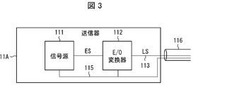
- FIG. 3 is a block diagram of the transmitter 11A according to this modification.
- a metal cable independent of the optical cable 113 is used as the metal cable 115 for transmitting the electric power supplied to the signal source 111.
- the metal cable 115 for transmitting the electric power supplied to the signal source 111 the metal cable constituting the composite cable 116 together with the optical cable 113 is used. Therefore, according to the transmitter 11A shown in FIG. 3, the power supply that is separated from the signal source 111 and that is electrically connected to the receiver 12 can supply power to the signal source 111. ..
- the configuration of the transmitter 11 is simplified. be able to.
- the metal cable 115 and the E / O converter 112 are electrically connected to each other, but may not be electrically connected to each other.
- the metal cable 115 and the E / O converter 112 are electrically connected to each other. According to this configuration, it is not necessary to provide a metal cable for transmitting electric power to the signal source 111 and the E / O converter 112 so as to run in parallel with the optical cable 113.
- the structure of the cable connected to the E / O converter 112 can be simplified as compared with the case where the composite cable is used as the cable connected to the E / O converter 112.
- the cost can be reduced.
- the transmission distance in the communication system 1 can be increased.
- the cable can be made smaller and / or lighter in size, or both. Further, when the cable is provided as an optical cable, the problem of voltage drop can be suppressed.
- the transmitter 11B which is a second modification of the transmitter 11, will be described with reference to FIG.
- FIG. 4 is a block diagram of the transmitter 11B according to this modification.
- a metal cable independent of the optical cable 113 is used as the metal cable 115 for transmitting the electric power supplied to the signal source 111.
- the metal cable 115 for transmitting the electric power supplied to the signal source 111 the metal cable constituting the composite cable 116 together with the optical cable 113 is used. Therefore, if the transmitter 11B shown in FIG. 4 is used, power can be supplied to the signal source 111 from a power source that is separated from the signal source 111 and is electrically connected to the receiver 12. ..
- the transmitter 11B shown in FIG. 4 includes a control unit 117.
- the metal cable 118 for transmitting the control signal supplied to the control unit 117 the metal cable constituting the composite cable 116 together with the optical cable 113 and the metal cable 115 is used. Therefore, according to the transmitter 11B shown in FIG. 4, the control signal can be supplied to the control unit 117 from the control signal source arranged in the vicinity of the receiver 12.
- the metal cable 115 and the E / O converter 112 are electrically connected to each other, but may not be electrically connected to each other. However, it is preferable that the metal cable 115 and the E / O converter 112 are electrically connected to each other.
- the structure of the cable connected to the E / O converter 112 can be simplified as compared with the case where the composite cable is used as the cable connected to the E / O converter 112. The cost can be reduced. Further, the transmission distance in the communication system 1 can be increased. In addition, the cable can be made smaller and / or lighter in size, or both. Further, when the cable is provided as an optical cable, the problem of voltage drop can be suppressed.
- the transmitter 11C which is a third modification of the transmitter 11, will be described with reference to FIG.
- FIG. 5 is a block diagram of the transmitter 11C according to this modification.
- the transmitter 11 shown in FIG. 1 is provided with a metal cable 115 for transmitting electric power supplied to the signal source 111.
- the transmitter 11C shown in FIG. 5 is provided with an electric connector 119 for connecting the metal cable 115 for transmitting the electric power supplied to the signal source 111. Therefore, according to the transmitter 11C shown in FIG. 5, the metal cable 115 that transmits the electric power supplied to the signal source 111 can be easily attached and detached. Further, in the present embodiment, the metal cable 115 may be electrically connected only to the signal source 111, or may be electrically connected to the signal source 111 and the E / O converter 112. It may be electrically connected only to the E / O converter 112.
- the metal cable 115, the signal source 111, and the E / O converter 112 are electrically connected to each other. According to this configuration, it is not necessary to provide a cable for supplying power to the signal source 111 or the E / O converter 112 via the optical connector 114 separately from the metal cable 115, and the signal source 111 is a single cable. And power can be transmitted to the E / O converter 112. Therefore, according to the above configuration, the structure of the cable provided via the optical connector 114 is simplified as compared with the case where it is electrically connected only to the signal source 111 or only the E / O converter 112. Since it can be done, the cost can be reduced. Further, the transmission distance in the communication system 1 can be increased. In addition, the cable can be made smaller and / or lighter in size, or both. Further, when the cable is provided as an optical cable, the problem of voltage drop can be suppressed.
- the transmitter 11D which is a fourth modification of the transmitter 11, will be described with reference to FIG.
- FIG. 6 is a block diagram of the transmitter 11D according to this modification.
- the electric signal input to the E / O converter 112 is the electric signal ES itself output from the signal source 111.
- the electric signal input to the E / O converter 112 is obtained by processing the electric signal ES output from the signal source 111 by the signal processing circuit 120.
- "Electrical signal ES" For example, when the signal source 111 is an image sensor, a serializer is used as the signal processing circuit 120, and the image signal and the clock signal output in parallel from the signal source 111 as the electric signal ES are serialized.
- the image signal and the clock signal output in parallel from the signal source 111 as the electric signal ES can be transmitted at high speed over a long distance without causing skew (variation in delay time).
- the number of cores constituting the optical cable 113 can be reduced.
- the number of E / O converters 112 can be reduced to one, for example.
- the metal cable 115 may be electrically connected only to the signal source 111, may be electrically connected to the signal source 111 and the signal processing circuit 120, or may be electrically connected to the signal source 111 and E /.
- the O converter 112 It may be electrically connected to the O converter 112, or it may be electrically connected to the signal source 111, the signal processing circuit 120 and the E / O converter 112, except that the metal cable 115 and the signal source. It is preferable that the 111, the E / O converter 112 and the signal processing circuit 120 are electrically connected to each other. According to this configuration, at least the signal source 111, the E / O converter 112 or the signal processing circuit 120 It is not necessary to provide a cable for supplying power to any one of them via the optical connector 114 separately from the metal cable 115, and the signal source 111, the E / O converter 112, and the signal processing circuit 120 are provided by one cable.
- the metal cable 115 and the signal source 111, the E / O converter 112, and the signal processing circuit 120 are compared with the case where they are not electrically connected to each other.
- the structure of the cable provided via the optical connector 114 can be simplified, so that the cost can be reduced, and the transmission distance in the communication system 1 can be increased.
- the cable can be used.
- miniaturization and weight reduction can be realized, and when the cable is provided as an optical cable, the problem of voltage drop can be suppressed.
- FIG. 7 is a plan view showing the configuration of the transmitter 11E according to the present modification.
- the first substrate 110a on which the signal source 111 is mounted and the second substrate 110b on which the E / O converter 112 is mounted are arranged apart from each other. Further, in the transmitter 11 shown in FIG. 2, the first substrate 110a on which the signal source 111 is mounted and the second substrate 110b on which the E / O converter 112 is mounted are examples of electrical connectors. It is connected by the board connectors 110a3 and 110b3. On the other hand, in the transmitter 11E shown in FIG. 7, the first substrate 110a on which the signal source 111 is mounted and the second substrate 110b on which the E / O converter 112 is mounted are arranged side by side and separated from each other. Has been done. Further, in the transmitter 11E shown in FIG.
- the first substrate 110a on which the signal source 111 is mounted and the second substrate 110b on which the E / O converter 112 is mounted are connected by a bonding wire 110c. ..
- the height of the space required for arranging the first substrate 110a and the second substrate 110b can be suppressed to a small size. As a result, it becomes easier to realize miniaturization of the transmitter 11 in the thickness direction.
- the signal source 111 is mounted on one main surface 110a1 of the first substrate 110a, and the E / O converter 112 is mounted on the other main surface 110b2 of the second substrate 110b.
- the main surface on which the signal source 111 is mounted may be either one main surface 110a1 or the other main surface 110a2, and the main surface on which the E / O converter 112 is mounted is one. Either the main surface 110b1 and the other main surface 110b2 may be used.
- FIG. 8 is a plan view showing the configuration of the transmitter 11F according to this modification.
- the first substrate 110a on which the signal source 111 is mounted and the second substrate 110b on which the E / O converter 112 is mounted are connected by a bonding wire 110c.
- a substrate-to-board connector 110a4 which is an example of an electric connector
- a board-to-board connector 110b4 which is an example of an electric connector
- the board-to-board connectors 110a4 and 110b4 are all angle connectors.
- the substrate-to-board connectors 110a4 and 110b4 can improve the durability when connecting the first substrate 110a and the second substrate 110b as compared with the bonding wire 110c.
- the signal source 111 is mounted on one main surface 110a1 of the first substrate 110a, and the E / O converter 112 is mounted on the other main surface 110b2 of the second substrate 110b.
- the main surface on which the signal source 111 is mounted may be either one main surface 110a1 or the other main surface 110a2, and the main surface on which the E / O converter 112 is mounted is one. Either the main surface 110b1 and the other main surface 110b2 may be used.
- FIG. 9 is a plan view showing the configuration of the transmitter 11G according to this modification.
- the first substrate 110a on which the signal source 111 is mounted and the second substrate 110b on which the E / O converter 112 is mounted are connected by a bonding wire 110c.
- a board-to-board connector 110a5 which is an example of an electric connector
- a board-to-board connector 110b5 which is an example of an electric connector
- the board-to-board connector 110a5 is an edge connector
- the board-to-board connector 110b5 is an angle connector.
- the first substrate 110a and the second substrate 110b are electrically connected by inserting the substrate-to-board connector 110a5 into the substrate-to-board connector 110b5.
- the substrate-to-board connectors 110a5 and 110b5 can improve the durability when connecting the first substrate 110a and the second substrate 110b as compared with the bonding wire 110c.
- the signal source 111 is mounted on one main surface 110a1 of the first substrate 110a, and the E / O converter 112 is mounted on the other main surface 110b2 of the second substrate 110b.
- the main surface on which the signal source 111 is mounted may be either one main surface 110a1 or the other main surface 110a2, and the main surface on which the E / O converter 112 is mounted is one. Either the main surface 110b1 and the other main surface 110b2 may be used.
- An optical cable and an optical connector provided at the end of the optical cable are provided, and the electric signal input to the E / O converter is the electric signal itself output from the signal source. Has been done.
- the transmitter according to the second aspect of the present invention in addition to the configuration of the transmitter according to the first aspect, at least a case for accommodating the signal source and the E / O converter is further provided, and the optical connector is the case.
- the configuration is adopted that it is provided at the end of the.
- a metal cable independent of the optical cable is further provided, and the metal cable is outside the transmitter. It is a metal cable for connecting the transmitting side power supply that can be connected to the transmitting side power supply and can supply power to the signal source and the E / O converter from the transmitting side power supply. There is.
- the transmitter according to the fourth aspect of the present invention in addition to the configuration of the transmitter according to the first or second aspect, it is a metal cable that transmits electric power to be supplied to the signal source, and constitutes a composite cable together with the optical cable.
- the configuration is that it is further equipped with a metal cable.
- an electric connector for connecting a metal cable for transmitting electric power supplied to the signal source in addition to the configuration of the transmitter according to any one of the first to fourth aspects, an electric connector for connecting a metal cable for transmitting electric power supplied to the signal source.
- the configuration is adopted that it is further equipped with.
- the first substrate and the second substrate are the first substrate.
- the board-to-board connector provided on each of the second boards is connected in an overlapping manner, and the board-to-board connector is output from the signal source and transmits the electric signal to the E / O converter.
- a terminal having a plurality of terminals, the terminal provided on the first substrate and the terminal provided on the second substrate have a shape complementary to each other, and the terminal provided on the first substrate.
- the configuration is adopted in which they are arranged in one row or a plurality of rows along the above.
- the receiver according to the seventh aspect of the present invention is a receiver that receives an optical signal transmitted from the transmitter according to any one of the first to sixth aspects, and converts the optical signal into an electric signal.
- a configuration is adopted in which a / E converter and a receiving circuit that processes an electric signal output from the O / E converter as an electric signal output from the signal source are provided.
- the transmitter according to any one aspect of the first to sixth aspects and the receiver according to the seventh aspect are included.
Landscapes
- Physics & Mathematics (AREA)
- Electromagnetism (AREA)
- Engineering & Computer Science (AREA)
- Computer Networks & Wireless Communication (AREA)
- Signal Processing (AREA)
- General Physics & Mathematics (AREA)
- Optics & Photonics (AREA)
- Optical Communication System (AREA)
Priority Applications (4)
| Application Number | Priority Date | Filing Date | Title |
|---|---|---|---|
| DE112020004173.5T DE112020004173T5 (de) | 2019-08-29 | 2020-08-31 | Sender, Empfänger und Kommunikationssystem |
| JP2021543099A JPWO2021040049A1 (zh) | 2019-08-29 | 2020-08-31 | |
| CN202080057195.7A CN114223153A (zh) | 2019-08-29 | 2020-08-31 | 发送器、接收器以及通信系统 |
| US17/635,469 US20220303011A1 (en) | 2019-08-29 | 2020-08-31 | Transmitter, receiver, and communication system |
Applications Claiming Priority (2)
| Application Number | Priority Date | Filing Date | Title |
|---|---|---|---|
| JP2019157441 | 2019-08-29 | ||
| JP2019-157441 | 2019-08-29 |
Publications (1)
| Publication Number | Publication Date |
|---|---|
| WO2021040049A1 true WO2021040049A1 (ja) | 2021-03-04 |
Family
ID=74683573
Family Applications (1)
| Application Number | Title | Priority Date | Filing Date |
|---|---|---|---|
| PCT/JP2020/032955 WO2021040049A1 (ja) | 2019-08-29 | 2020-08-31 | 送信器、受信器、及び通信システム |
Country Status (5)
| Country | Link |
|---|---|
| US (1) | US20220303011A1 (zh) |
| JP (1) | JPWO2021040049A1 (zh) |
| CN (1) | CN114223153A (zh) |
| DE (1) | DE112020004173T5 (zh) |
| WO (1) | WO2021040049A1 (zh) |
Citations (7)
| Publication number | Priority date | Publication date | Assignee | Title |
|---|---|---|---|---|
| JP2007260066A (ja) * | 2006-03-28 | 2007-10-11 | Pentax Corp | 内視鏡装置 |
| WO2012046856A1 (ja) * | 2010-10-08 | 2012-04-12 | オリンパスメディカルシステムズ株式会社 | 撮像装置 |
| JP2014137584A (ja) * | 2013-01-18 | 2014-07-28 | Olympus Corp | 光伝送モジュールおよび撮像装置 |
| JP2016167794A (ja) * | 2015-03-03 | 2016-09-15 | キヤノン株式会社 | 伝送制御装置および制御方法、並びに、複合現実感提示装置 |
| WO2018092234A1 (ja) * | 2016-11-17 | 2018-05-24 | オリンパス株式会社 | 光モジュール、撮像モジュールおよび内視鏡 |
| JP2018171324A (ja) * | 2017-03-31 | 2018-11-08 | Hoya株式会社 | 内視鏡、内視鏡システム |
| WO2019058634A1 (ja) * | 2017-09-25 | 2019-03-28 | オリンパス株式会社 | 光モジュール |
Family Cites Families (6)
| Publication number | Priority date | Publication date | Assignee | Title |
|---|---|---|---|---|
| US9525488B2 (en) * | 2010-05-02 | 2016-12-20 | Corning Optical Communications LLC | Digital data services and/or power distribution in optical fiber-based distributed communications systems providing digital data and radio frequency (RF) communications services, and related components and methods |
| US20150078740A1 (en) * | 2013-09-19 | 2015-03-19 | RADIUS UNIVERSAL, A Limited Liability Company of the State of New York | Fiber optic communications network |
| JP6231954B2 (ja) * | 2014-07-23 | 2017-11-15 | 株式会社フジクラ | 画像送受信システム、アクティブケーブルの監視方法、アクティブケーブルの制御方法、画像送信装置、画像受信装置、及びアクティブケーブル |
| JPWO2018221533A1 (ja) * | 2017-05-29 | 2020-03-19 | 株式会社フジクラ | アクティブ光ケーブル、アクティブ光ケーブルの制御方法、及び、アクティブ光ケーブルの配線方法 |
| CN109587427A (zh) * | 2018-12-12 | 2019-04-05 | 深圳市易飞扬通信技术有限公司 | 高清晰多媒体接口有源光缆电路 |
| JP7345309B2 (ja) * | 2019-08-02 | 2023-09-15 | 京セラ株式会社 | 光ファイバー給電システム |
-
2020
- 2020-08-31 US US17/635,469 patent/US20220303011A1/en not_active Abandoned
- 2020-08-31 CN CN202080057195.7A patent/CN114223153A/zh active Pending
- 2020-08-31 WO PCT/JP2020/032955 patent/WO2021040049A1/ja active Application Filing
- 2020-08-31 JP JP2021543099A patent/JPWO2021040049A1/ja active Pending
- 2020-08-31 DE DE112020004173.5T patent/DE112020004173T5/de active Pending
Patent Citations (7)
| Publication number | Priority date | Publication date | Assignee | Title |
|---|---|---|---|---|
| JP2007260066A (ja) * | 2006-03-28 | 2007-10-11 | Pentax Corp | 内視鏡装置 |
| WO2012046856A1 (ja) * | 2010-10-08 | 2012-04-12 | オリンパスメディカルシステムズ株式会社 | 撮像装置 |
| JP2014137584A (ja) * | 2013-01-18 | 2014-07-28 | Olympus Corp | 光伝送モジュールおよび撮像装置 |
| JP2016167794A (ja) * | 2015-03-03 | 2016-09-15 | キヤノン株式会社 | 伝送制御装置および制御方法、並びに、複合現実感提示装置 |
| WO2018092234A1 (ja) * | 2016-11-17 | 2018-05-24 | オリンパス株式会社 | 光モジュール、撮像モジュールおよび内視鏡 |
| JP2018171324A (ja) * | 2017-03-31 | 2018-11-08 | Hoya株式会社 | 内視鏡、内視鏡システム |
| WO2019058634A1 (ja) * | 2017-09-25 | 2019-03-28 | オリンパス株式会社 | 光モジュール |
Also Published As
| Publication number | Publication date |
|---|---|
| CN114223153A (zh) | 2022-03-22 |
| DE112020004173T5 (de) | 2022-05-19 |
| JPWO2021040049A1 (zh) | 2021-03-04 |
| US20220303011A1 (en) | 2022-09-22 |
Similar Documents
| Publication | Publication Date | Title |
|---|---|---|
| US7798850B2 (en) | Cable assembly having enhanced interconnection means thereof | |
| US20060088251A1 (en) | Integrated optical fiber and electro-optical converter | |
| US10320482B2 (en) | Connector module and optical signal processing device connected thereto | |
| US8696218B2 (en) | Optoelectronic signal conversion module | |
| JP2006030868A (ja) | 光電気複合型コネクタ及びそれを用いた基板 | |
| US8976510B2 (en) | Cable assembly and electronic device | |
| CN114513254B (zh) | 一种可动态改变传输方向的高速光电传输系统及线缆 | |
| WO2022222342A1 (zh) | 一种光模块以及光通信设备 | |
| WO2021040049A1 (ja) | 送信器、受信器、及び通信システム | |
| TWI572925B (zh) | Hdmi數據傳輸裝置 | |
| WO2021040047A1 (ja) | 送信器、受信器、及び通信システム | |
| US8851764B2 (en) | Electronic device with optical universal serial bus connector | |
| US6902427B2 (en) | Integrated S-video and composite video port | |
| JP3784283B2 (ja) | 光伝送装置 | |
| US7021943B2 (en) | Optical transmission module | |
| JP2005285043A (ja) | センサ用ケーブル | |
| JP2020087936A (ja) | コネクタ及びケーブル | |
| JP2013025984A (ja) | 配線ユニット | |
| CN113660405B (zh) | 一种摄像机构及电子设备 | |
| US20110187870A1 (en) | Video/Audio Module Applied to Computer System | |
| US11265087B2 (en) | Compact optic-connecting device | |
| US20220029320A1 (en) | Cable and image transmission system | |
| JP2013128281A (ja) | コンピュータデータ伝送システム及びコンピュータマザーボード | |
| WO2021212375A1 (zh) | 一种光器件及光模块 | |
| US8867870B2 (en) | Optical module fabricated on folded printed circuit board |
Legal Events
| Date | Code | Title | Description |
|---|---|---|---|
| 121 | Ep: the epo has been informed by wipo that ep was designated in this application |
Ref document number: 20859397 Country of ref document: EP Kind code of ref document: A1 |
|
| ENP | Entry into the national phase |
Ref document number: 2021543099 Country of ref document: JP Kind code of ref document: A |
|
| 122 | Ep: pct application non-entry in european phase |
Ref document number: 20859397 Country of ref document: EP Kind code of ref document: A1 |