WO2021039991A1 - リーン車両 - Google Patents
リーン車両 Download PDFInfo
- Publication number
- WO2021039991A1 WO2021039991A1 PCT/JP2020/032677 JP2020032677W WO2021039991A1 WO 2021039991 A1 WO2021039991 A1 WO 2021039991A1 JP 2020032677 W JP2020032677 W JP 2020032677W WO 2021039991 A1 WO2021039991 A1 WO 2021039991A1
- Authority
- WO
- WIPO (PCT)
- Prior art keywords
- leg shield
- front wheel
- vehicle
- lean
- link mechanism
- Prior art date
- Legal status (The legal status is an assumption and is not a legal conclusion. Google has not performed a legal analysis and makes no representation as to the accuracy of the status listed.)
- Ceased
Links
Images


Classifications
-
- B—PERFORMING OPERATIONS; TRANSPORTING
- B62—LAND VEHICLES FOR TRAVELLING OTHERWISE THAN ON RAILS
- B62K—CYCLES; CYCLE FRAMES; CYCLE STEERING DEVICES; RIDER-OPERATED TERMINAL CONTROLS SPECIALLY ADAPTED FOR CYCLES; CYCLE AXLE SUSPENSIONS; CYCLE SIDECARS, FORECARS, OR THE LIKE
- B62K5/00—Cycles with handlebars, equipped with three or more main road wheels
- B62K5/10—Cycles with handlebars, equipped with three or more main road wheels with means for inwardly inclining the vehicle body on bends
-
- B—PERFORMING OPERATIONS; TRANSPORTING
- B60—VEHICLES IN GENERAL
- B60G—VEHICLE SUSPENSION ARRANGEMENTS
- B60G21/00—Interconnection systems for two or more resiliently-suspended wheels, e.g. for stabilising a vehicle body with respect to acceleration, deceleration or centrifugal forces
- B60G21/007—Interconnection systems for two or more resiliently-suspended wheels, e.g. for stabilising a vehicle body with respect to acceleration, deceleration or centrifugal forces means for adjusting the wheel inclination
-
- B—PERFORMING OPERATIONS; TRANSPORTING
- B62—LAND VEHICLES FOR TRAVELLING OTHERWISE THAN ON RAILS
- B62J—CYCLE SADDLES OR SEATS; AUXILIARY DEVICES OR ACCESSORIES SPECIALLY ADAPTED TO CYCLES AND NOT OTHERWISE PROVIDED FOR, e.g. ARTICLE CARRIERS OR CYCLE PROTECTORS
- B62J17/00—Weather guards for riders; Fairings or stream-lining parts not otherwise provided for
- B62J17/02—Weather guards for riders; Fairings or stream-lining parts not otherwise provided for shielding only the rider's front
- B62J17/06—Leg guards
-
- B—PERFORMING OPERATIONS; TRANSPORTING
- B62—LAND VEHICLES FOR TRAVELLING OTHERWISE THAN ON RAILS
- B62J—CYCLE SADDLES OR SEATS; AUXILIARY DEVICES OR ACCESSORIES SPECIALLY ADAPTED TO CYCLES AND NOT OTHERWISE PROVIDED FOR, e.g. ARTICLE CARRIERS OR CYCLE PROTECTORS
- B62J17/00—Weather guards for riders; Fairings or stream-lining parts not otherwise provided for
- B62J17/08—Hoods protecting the rider
- B62J17/086—Frame mounted hoods specially adapted for motorcycles or the like
-
- B—PERFORMING OPERATIONS; TRANSPORTING
- B62—LAND VEHICLES FOR TRAVELLING OTHERWISE THAN ON RAILS
- B62J—CYCLE SADDLES OR SEATS; AUXILIARY DEVICES OR ACCESSORIES SPECIALLY ADAPTED TO CYCLES AND NOT OTHERWISE PROVIDED FOR, e.g. ARTICLE CARRIERS OR CYCLE PROTECTORS
- B62J25/00—Foot-rests; Knee grips; Passenger hand-grips
- B62J25/04—Floor-type foot rests
-
- B—PERFORMING OPERATIONS; TRANSPORTING
- B62—LAND VEHICLES FOR TRAVELLING OTHERWISE THAN ON RAILS
- B62K—CYCLES; CYCLE FRAMES; CYCLE STEERING DEVICES; RIDER-OPERATED TERMINAL CONTROLS SPECIALLY ADAPTED FOR CYCLES; CYCLE AXLE SUSPENSIONS; CYCLE SIDECARS, FORECARS, OR THE LIKE
- B62K5/00—Cycles with handlebars, equipped with three or more main road wheels
- B62K5/02—Tricycles
- B62K5/05—Tricycles characterised by a single rear wheel
-
- B—PERFORMING OPERATIONS; TRANSPORTING
- B62—LAND VEHICLES FOR TRAVELLING OTHERWISE THAN ON RAILS
- B62K—CYCLES; CYCLE FRAMES; CYCLE STEERING DEVICES; RIDER-OPERATED TERMINAL CONTROLS SPECIALLY ADAPTED FOR CYCLES; CYCLE AXLE SUSPENSIONS; CYCLE SIDECARS, FORECARS, OR THE LIKE
- B62K5/00—Cycles with handlebars, equipped with three or more main road wheels
- B62K5/02—Tricycles
- B62K5/06—Frames for tricycles
-
- B—PERFORMING OPERATIONS; TRANSPORTING
- B62—LAND VEHICLES FOR TRAVELLING OTHERWISE THAN ON RAILS
- B62K—CYCLES; CYCLE FRAMES; CYCLE STEERING DEVICES; RIDER-OPERATED TERMINAL CONTROLS SPECIALLY ADAPTED FOR CYCLES; CYCLE AXLE SUSPENSIONS; CYCLE SIDECARS, FORECARS, OR THE LIKE
- B62K5/00—Cycles with handlebars, equipped with three or more main road wheels
- B62K5/08—Cycles with handlebars, equipped with three or more main road wheels with steering devices acting on two or more wheels
-
- B—PERFORMING OPERATIONS; TRANSPORTING
- B60—VEHICLES IN GENERAL
- B60G—VEHICLE SUSPENSION ARRANGEMENTS
- B60G2300/00—Indexing codes relating to the type of vehicle
- B60G2300/12—Cycles; Motorcycles
- B60G2300/122—Trikes
-
- B—PERFORMING OPERATIONS; TRANSPORTING
- B62—LAND VEHICLES FOR TRAVELLING OTHERWISE THAN ON RAILS
- B62J—CYCLE SADDLES OR SEATS; AUXILIARY DEVICES OR ACCESSORIES SPECIALLY ADAPTED TO CYCLES AND NOT OTHERWISE PROVIDED FOR, e.g. ARTICLE CARRIERS OR CYCLE PROTECTORS
- B62J17/00—Weather guards for riders; Fairings or stream-lining parts not otherwise provided for
- B62J17/10—Ventilation or air guiding devices forming part of fairings
Definitions
- the present invention relates to a lean vehicle.
- Patent Document 1 discloses a lean vehicle provided with a leaning drive mechanism for controlling the inclination of the vehicle in the left-right direction.
- the lean vehicle disclosed in Patent Document 1 includes a vehicle body, a left wheel located on the left side of the vehicle body, a right wheel located on the right side of the vehicle body, a leaning mechanism, and a leaning drive mechanism.
- the leaning mechanism includes a support arm that supports the left wheel and the right wheel and is rotatably supported by the vehicle body around a rotation axis extending in the front-rear direction of the vehicle body.
- the leaning drive mechanism includes a drive source that generates a driving force for rotating the support arm with respect to the vehicle body.
- the leaning drive mechanism moves the left wheel and the right wheel in the vertical direction by rotating the support arm of the leaning mechanism by a driving force generated by a drive source. Thereby, it is possible to control the inclination of the lean vehicle in the left-right direction.
- the lean actuator is placed on the left front wheel located to the left of the vehicle body and to the right of the vehicle body. It is located behind the right front wheel where it is located. Therefore, in the lean vehicle, the lean actuator is protected from stones, sand and dust, rainwater, etc. that are flipped up by the left front wheel or the right front wheel when the lean vehicle is running, and at the front of the lean vehicle.
- a vehicle body structure capable of rectifying the airflow flowing toward the lean vehicle.
- the front portion of the lean vehicle is provided with the lean actuator and the left front wheel and the right front wheel that are supported by a link mechanism so as to be movable in the vertical direction with respect to the vehicle body body. Therefore, the lean vehicle can protect the lean actuator while ensuring the movable range of the left front wheel and the right front wheel, and can rectify the airflow flowing toward the lean vehicle at the front portion of the lean vehicle. It is desired to have a structure.
- the present invention protects the lean actuator in a lean vehicle including a left front wheel located to the left of the vehicle body, a right front wheel located to the right of the vehicle body, and a lean actuator for controlling the inclination of the vehicle in the left-right direction. It is an object of the present invention to provide a configuration having a vehicle body structure capable of rectifying an air flow flowing toward the lean vehicle at the front portion of the lean vehicle.
- the present inventors use the lean actuator in a lean vehicle provided with a left front wheel located to the left of the vehicle body, a right front wheel located to the right of the vehicle body, and a lean actuator for controlling the inclination of the vehicle in the left-right direction.
- a vehicle body structure that can be protected and that can rectify the airflow flowing toward the lean vehicle at the front of the lean vehicle is examined.
- the present inventors have come up with the following configuration.
- the lean vehicle is between the vehicle body, the left front wheel located to the left of the vehicle body, the right front wheel located to the right of the vehicle body, and the left front wheel and the right front wheel.
- a link mechanism that is located and supports the left front wheel and the right front wheel so as to be movable in the vertical direction with respect to the vehicle body body, and at least a part of the vehicle is located behind the link mechanism when viewed in the left-right direction.
- the link mechanism enables the left front wheel and the right front wheel to move in the vertical direction with respect to the vehicle body body.
- the lean vehicle that includes a connected lean actuator and tilts to the left when turning to the left and to the right when turning to the right.
- the lean vehicle comprises a leg shield that is located behind the left front wheel and the right front wheel and at least partially located between the left front wheel and the right front wheel and the driver's leg.
- the leg shield intermediate portion located in the middle in the left-right direction is more than the leg shield left portion located to the left of the leg shield intermediate portion and the leg shield right portion located to the right of the leg shield intermediate portion. It is formed so as to project forward and cover at least a part of the left portion of the lean actuator which is the left portion of the lean actuator and the right portion of the lean actuator which is the right portion of the lean actuator.
- the lean actuator has at least a part located behind the link mechanism when the vehicle is viewed in the left-right direction and at least a part in the left front wheel and the right front wheel when the vehicle is viewed in the front-rear direction. It is located between. Further, a leg shield located behind the left front wheel and the right front wheel and at least partially located between the left front wheel and the right front wheel and the driver's leg is located in the middle in the left-right direction and in front. By having the protruding leg shield intermediate portion, the airflow flowing from the front of the lean vehicle between the left front wheel and the right front wheel is divided into left and right by the leg shield intermediate portion, and the leg shield left portion and the leg shield are separated. It flows backward along each of the right parts.
- the airflow avoids the lean actuator in which at least a part of the left portion of the lean actuator and the right portion of the lean actuator is covered by the leg shield intermediate portion, and the driver's leg in which at least a part is covered by the leg shield. Then, it flows behind the lean vehicle.
- the air flow includes not only the flow of gas such as air, but also the movement of liquids such as rain and solids such as stones, sand, and dust carried with the gas. Further, a part of the liquid and solid matter contained in the air flow and at least a part of the solid matter and liquid bounced up by the left front wheel or the right front wheel are the left portion of the lean actuator and the lean portion. It comes into contact with the middle part of the leg shield covering at least a part of the right side of the actuator and is carried to the rear of the lean vehicle by the air flow.
- the leg shield can prevent the airflow containing the solid matter and the liquid flowing from the front of the lean vehicle between the left front wheel and the right front wheel from hitting the lean actuator and the leg of the driver.
- the leg shield protects the lean actuator by the leg shield middle portion protruding in front of the leg shield left portion and the leg shield right portion, and also protects the leg shield intermediate portion, the leg shield left portion, and the leg shield right portion. Can rectify the airflow.
- the lean actuator can be protected in a lean vehicle provided with a left front wheel located to the left of the vehicle body, a right front wheel located to the right of the vehicle body, and a lean actuator for controlling the inclination of the vehicle in the left-right direction. Moreover, it is possible to provide a configuration having a vehicle body structure capable of rectifying the airflow flowing toward the lean vehicle at the front portion of the lean vehicle.
- the lean vehicle of the present invention preferably includes the following configurations.
- the lean vehicle further includes a front vehicle body cover that covers the front portion of the vehicle body located in front of the leg shield in the vehicle body.
- the width of the middle portion of the leg shield in the left-right direction is larger than the width of the front portion of the vehicle body body or the front portion of the vehicle body cover in the left-right direction.
- the leg shield can more reliably prevent the airflow from hitting the lean actuator and the driver's leg.
- the lean actuator can be protected in a lean vehicle provided with a left front wheel located to the left of the vehicle body, a right front wheel located to the right of the vehicle body, and a lean actuator for controlling the inclination of the vehicle in the left-right direction. Moreover, it is possible to provide a configuration having a vehicle body structure capable of more reliably rectifying the airflow flowing toward the lean vehicle at the front portion of the lean vehicle.
- the lean vehicle of the present invention preferably includes the following configurations. At least one of the left portion of the leg shield and the right portion of the leg shield includes a leg shield lower inclined portion located rearward toward the lower edge.
- the leg shield can more reliably prevent the airflow from hitting the lean actuator and the driver's leg.
- the lean actuator can be protected in a lean vehicle provided with a left front wheel located to the left of the vehicle body, a right front wheel located to the right of the vehicle body, and a lean actuator for controlling the inclination of the vehicle in the left-right direction. Moreover, it is possible to provide a configuration having a vehicle body structure capable of more reliably rectifying the airflow flowing toward the lean vehicle at the front portion of the lean vehicle.
- the lean vehicle of the present invention preferably includes the following configurations.
- the width of the front portion of the leg shield intermediate portion in the left-right direction becomes smaller toward the lower edge of the leg shield intermediate portion.
- the leg shield can more reliably prevent the airflow from hitting the lean actuator and the driver's leg.
- the lean actuator can be protected in a lean vehicle provided with a left front wheel located to the left of the vehicle body, a right front wheel located to the right of the vehicle body, and a lean actuator for controlling the inclination of the vehicle in the left-right direction. Moreover, it is possible to provide a configuration having a vehicle body structure capable of more reliably rectifying the airflow flowing toward the lean vehicle at the front portion of the vehicle.
- the lean vehicle of the present invention preferably includes the following configurations.
- the width of the middle part of the leg shield in the left-right direction is larger toward the rear end of the middle part of the leg shield.
- the leg shield can more reliably prevent the airflow from hitting the lean actuator and the driver's leg.
- the lean actuator can be protected in a lean vehicle provided with a left front wheel located to the left of the vehicle body, a right front wheel located to the right of the vehicle body, and a lean actuator for controlling the inclination of the vehicle in the left-right direction. Moreover, it is possible to provide a configuration having a vehicle body structure capable of more reliably rectifying the airflow flowing toward the lean vehicle at the front portion of the lean vehicle.
- the lean vehicle of the present invention preferably includes the following configurations.
- the left portion of the leg shield includes a left inclined portion of the leg shield located rearward toward the left edge.
- the right portion of the leg shield includes a leg shield right inclined portion located rearward toward the right edge.
- the leg shield can more reliably prevent the airflow from hitting the lean actuator and the driver's leg.
- the lean actuator can be protected in a lean vehicle provided with a left front wheel located to the left of the vehicle body, a right front wheel located to the right of the vehicle body, and a lean actuator for controlling the inclination of the vehicle in the left-right direction. Moreover, it is possible to provide a configuration having a vehicle body structure capable of more reliably rectifying the airflow flowing toward the lean vehicle at the front portion of the lean vehicle.
- the lean vehicle of the present invention preferably includes the following configurations.
- the vertical central portion of the leg shield intermediate portion covers at least a part of the left portion of the lean actuator and the right portion of the lean actuator.
- the leg shield can more reliably prevent the airflow from hitting the lean actuator and the driver's leg.
- the lean vehicle of the present invention preferably includes the following configurations.
- the left front wheel and the right front wheel are steering wheels.
- the airflow is generated by the lean actuator and the driver while avoiding interference with the left front wheel and the right front wheel by the leg shield having the above configuration. You can more reliably prevent it from hitting the leg.
- This specification describes an embodiment of a lean vehicle according to the present invention.
- the lean vehicle is a vehicle that turns in an inclined posture.
- a lean vehicle is a vehicle that tilts to the left when turning to the left and to the right when turning to the right in the left-right direction of the vehicle.
- the lean vehicle may be a single-seater vehicle or a vehicle that can accommodate a plurality of people.
- the lean vehicle includes all vehicles that turn in an inclined posture, such as a three-wheeled vehicle or a four-wheeled vehicle.
- the leg shield means a member which is a part of a vehicle body cover, is located behind the left front wheel and the right front wheel, and covers at least a part of the driver's leg when the lean vehicle is viewed rearward.
- the leg shields are a leg shield intermediate portion located in the middle portion in the left-right direction, a leg shield left portion located to the left of the leg shield intermediate portion, and a leg shield right portion located to the right of the leg shield intermediate portion. And have.
- the leg shield intermediate portion covers at least a part of the lean actuator that drives the lean mechanism.
- a vehicle body structure capable of rectifying an air flow flowing toward the lean vehicle at the front portion of the lean vehicle is provided. It is possible to provide a configuration having.
- FIG. 1 is a left side view showing an outline of the overall configuration of the lean vehicle according to the embodiment.
- FIG. 2 is a front view showing an outline of the overall configuration of the lean vehicle.
- FIG. 3 is an exploded perspective view showing a schematic structure of the vehicle body frame.
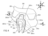
- FIG. 4 is a perspective view of the leg shield viewed from the rear.
- FIG. 5 is a sectional view taken along line VV in FIG.
- FIG. 6 is a plan view schematically showing the positional relationship between the vehicle body frame, the vehicle body cover, and the driver.
- FIG. 7 is a schematic view of the link mechanism when the vehicle body frame is tilted to the left when viewed from the rear.
- FIG. 8 is a schematic view of the link mechanism when the vehicle body frame is tilted to the right when viewed from the rear.
- FIG. 9 is a side-by-side view of a front view of the lean vehicle and a plan view schematically showing the shape and arrangement of the vehicle body cover in the lean vehicle.
- the arrow F in the figure indicates the forward direction of the lean vehicle 1.
- the arrow B in the figure indicates the rear direction of the lean vehicle 1.
- the arrow U in the figure indicates the upward direction of the lean vehicle 1.
- the arrow D in the figure indicates the downward direction of the lean vehicle 1.
- the arrow R in the figure indicates the right direction of the lean vehicle 1.
- the arrow L in the figure indicates the left direction of the lean vehicle 1.
- the front-rear direction, the left-right direction, and the up-down direction of the lean vehicle 1 mean the front-back left-right direction, the left-right direction, and the up-down direction with respect to the lean vehicle 1 when viewed from the driver who drives the lean vehicle 1, respectively. ..
- the lean vehicle 1 of the present embodiment turns by inclining the vehicle body frame 21 in the left-right direction with respect to the vertical direction. Therefore, in FIGS. 7 and 8 showing the state in which the vehicle body frame 21 is tilted, the direction with respect to the vehicle body frame 21 is defined as follows in addition to the direction with respect to the lean vehicle 1 described above.
- the arrow FU in the figure indicates the upward direction of the vehicle body frame 21.
- the arrow FD in the figure indicates the downward direction of the vehicle body frame 21.
- the arrow FR in the figure indicates the right direction of the vehicle body frame 21.
- the arrow FL in the figure indicates the left direction of the vehicle body frame 21.
- the left-right direction and the up-down direction of the vehicle body frame 21 mean the left-right direction and the up-down direction with respect to the body frame 21 when viewed from the occupant driving the lean vehicle 1, respectively.
- FIG. 1 is a left side view showing an outline of the overall configuration of the lean vehicle 1 according to the embodiment.
- FIG. 2 is a front view showing an outline of the overall configuration of the lean vehicle 1.
- FIG. 9 is a side-by-side view of FIGS. 1 and 6.
- the lean vehicle 1 includes a vehicle body 2, a pair of left and right front wheels 3, a rear wheel 4, a link mechanism 5, a steering mechanism 6, a shock absorber 7, a power unit 8 (drive source), and a link mechanism drive motor 55. (Lean actuator) is provided.
- the lean vehicle 1 of the present embodiment is a vehicle that inclines to the left when turning to the left and to the right when turning to the right. That is, the lean vehicle 1 of the present embodiment tilts the vehicle body 2 and the pair of left and right front wheels 3 to the left when turning to the left, and tilts the vehicle body 2 and the pair of left and right front wheels 3 to the right when turning to the right. It is a vehicle that tilts to the right.
- the vehicle body body 2 has a vehicle body frame 21, a rear arm 23, a vehicle body cover 26, and a seat 27.
- the vehicle body frame 21 is in an upright state.
- the vehicle body frame 21 is premised on an upright state.
- the upright state of the vehicle body frame 21 means that the vertical direction of the vehicle body frame 21 is the same as the vertical direction.
- the vehicle body frame 21 supports mounting parts mounted on the lean vehicle 1, such as the vehicle body cover 26, the seat 27, and the power unit 8. Although not particularly shown, specifically, the vehicle body frame 21 supports the link mechanism 5 and the link mechanism drive motor 55 at the front portion. The vehicle body frame 21 supports the rear arm support portion 24 (see FIG. 3), the seat 27, and the power unit 8 at the rear portion.
- the power unit 8 has, for example, a motor that is a power generation source.
- the power unit 8 may have an engine as the power generation source, or may have a hybrid system in which an engine and a motor are combined.
- FIG. 3 is an exploded perspective view showing a schematic configuration of a vehicle body frame 21, a pair of left and right front wheels 3, a rear wheel 4, a link mechanism 5, and a steering mechanism 6.
- the vehicle body frame 21 has a main skeleton portion 21a, a link mechanism support portion 22 (front portion of the vehicle body body), a rear arm support portion 24, and a handle support portion 25.
- the main skeleton portion 21a is a frame constituting the skeleton of the vehicle body body 2 of the lean vehicle 1.
- the main skeleton portion 21a extends linearly in the front-rear direction. That is, the width of the main skeleton portion 21a in the left-right direction is smaller than the length of the main skeleton portion 21a in the front-rear direction.
- the main skeleton portion 21a includes an anterior skeleton portion 211 and a posterior skeleton portion 212.
- the anterior skeleton portion 211 and the posterior skeleton portion 212 are connected in a state of being arranged in the front-rear direction.
- the anterior skeleton portion 211 is located in front of the posterior skeleton portion 212 in the main skeleton portion 21a.
- the anterior skeleton portion 211 extends in the anteroposterior direction.
- the anterior skeleton portion 211 has a pair of anterior skeleton side wall portions 211a and an anterior skeleton bottom wall portion 211b.
- the pair of anterior skeleton side wall portions 211a are located side by side in the left-right direction and are long in the front-rear direction.
- the front skeleton bottom wall portion 211b connects the lower ends of the pair of front skeleton side wall portions 211a.
- the pair of anterior skeleton side wall portions 211a and the anterior skeleton bottom wall portion 211b are connected by welding, for example.
- the pair of front skeleton side wall portions 211a and front skeleton bottom wall portion 211b may be connected by adhesion, bolts, or the like, or may be integrally formed.
- the height dimension of the pair of front skeleton side wall portions 211a is lower in the rear portion than in the front portion, respectively.
- the front skeleton portion 211 can be arranged at the feet of the driver seated on the seating surface 27c of the seat 27. Therefore, the main skeleton portion 21a can be arranged in the lower part of the lean vehicle 1. As a result, the center of gravity of the lean vehicle 1 can be lowered.
- the height in the present embodiment means the height from the road surface on which the lean vehicle 1 travels.
- the posterior skeleton portion 212 is located behind the anterior skeleton portion 211 in the main skeleton portion 21a.
- the posterior skeleton portion 212 extends in the anteroposterior direction.
- the posterior skeleton portion 212 has a pair of posterior skeleton side wall portions 212a and a plurality of posterior skeleton beam portions 212b.
- the pair of posterior skeleton side wall portions 212a are located side by side in the left-right direction and are long in the front-rear direction.
- the plurality of posterior skeleton beam portions 212b connect a pair of posterior skeleton side wall portions 212a in the left-right direction.
- the vertical dimension of the rear skeleton portion 212 is larger than the vertical dimension of the front skeleton portion 211.
- the left-right dimension of the posterior skeleton portion 212 is smaller than the left-right dimension of the front skeleton portion 211.
- the front skeleton portion 211 supports the link mechanism support portion 22 and the link mechanism drive motor 55 at the front portion (see FIGS. 3 and 6).
- the rear skeleton portion 212 supports the power unit 8 and the seat 27 at the front portion, and supports the rear arm support portion 24 at the rear portion (see FIGS. 1 and 3).
- the main skeleton portion 21a is located between the left step 261 and the right step 262 provided on the vehicle body cover main body 26a in a plan view. That is, the main skeleton portion 21a is linear in the front-rear direction between both legs of the driver when the driver puts his / her feet on the left step 261 and the right step 262 while the driver is seated on the seating surface 27c described later of the seat 27. Extends to.
- the seat 27 is supported by the rear skeleton portion 212 of the vehicle body frame 21.
- the seat 27 has a seating portion 27a and a seat back 27b.
- the seating portion 27a of the seat 27 is supported by the upper portion of the posterior skeleton portion 212.
- the upper surface of the seating portion 27a is a seating surface 27c on which the driver is seated.
- the link mechanism support portion 22 is connected to the front end of the anterior skeleton portion 211.
- the link mechanism support portion 22 supports the link mechanism 5 described later.
- the link mechanism 5 supports a pair of left and right front wheels 3. That is, the link mechanism support portion 22 supports the pair of left and right front wheels 3 via the link mechanism 5.
- the link mechanism support portion 22 constitutes a front portion of the vehicle body body 2 located in front of the leg shield described later.
- the front portion and the upper portion of the link mechanism support portion 22 are covered with the front vehicle body cover 267 of the vehicle body cover 26 described later.
- the detailed configuration of the link mechanism 5 will be described later.
- the pair of left and right front wheels 3 includes a left front wheel 31 located to the left of the vehicle body frame 21 and a right front wheel 32 located to the right of the vehicle body frame 21.
- the left arm mechanism 51 of the link mechanism 5, which will be described later, extends from the link mechanism support portion 22 to the left so as to support the left front wheel 31 with respect to the vehicle body frame 21.
- the right arm mechanism 52 of the link mechanism 5, which will be described later, extends from the link mechanism support portion 22 to the right so as to support the right front wheel 32 with respect to the vehicle body frame 21.
- a shock absorber support portion 28 that supports the shock absorber 7 is arranged between the link mechanism support portion 22 and the anterior skeleton portion 211.
- the shock absorber support portion 28 is connected to the upper portion of the link mechanism support portion 22 and the front lower end portion of the handle support portion 25 connected to the front skeleton portion 211.
- the shock absorber support portion 28 has a shock absorber support main body portion 28a and a tower portion 28b.
- the shock absorber support main body 28a is a cylindrical member and supports the base end portion of the tower portion 28b extending in the vertical direction.
- the shock absorber support main body 28a is connected to the front lower end of the link mechanism support 22 and the handle support 25.
- an output shaft 56 of the link mechanism drive motor 55 and a transmission member for transmitting the driving force of the link mechanism drive motor 55 from the output shaft 56 to the link mechanism 5 are arranged inside the shock absorber support main body 28a. Has been done.
- the shock absorber 7 includes a left shock absorber 71 and a right shock absorber 72.
- the left shock absorber 71 is provided so as to connect the tower portion 28b and the upper left arm member 511 of the link mechanism 5, which will be described later.
- the right shock absorber 72 is provided so as to connect the tower portion 28b and the upper right arm member 521 of the link mechanism 5, which will be described later.
- the left shock absorber 71 and the right shock absorber 72 have a spring and a damper, respectively.
- the left shock absorber 71 cushions the force input from the road surface to the left front wheel 31, and positions the left front wheel 31 with respect to the vehicle body frame 21 (see FIG. 1).
- the right shock absorber 72 buffers the force input from the road surface to the right front wheel 32, and positions the right front wheel 32 with respect to the vehicle body frame 21 (see FIG. 1).
- the handle support portion 25 is connected to the upper portion of the front portion of the front skeleton portion 211, and extends upward from the upper portion of the front skeleton portion 211.
- a part of the handle support portion 25 may extend upward from the upper portion of the main skeleton portion 21a other than the front skeleton portion 211. That is, as long as at least a part of the handle support portion 25 extends upward from the upper part of the front skeleton portion 211, the handle support portion 25 may be provided in the main skeleton portion 21a in any way.
- the handle support portion 25 may extend upward from the upper portion of a portion other than the front skeleton portion 211. That is, the handle support portion 25 may extend upward from the upper portion of the main skeleton portion 21a.
- the handle support portion 25 supports the bar handle 61 and the steering shaft 62 of the steering mechanism 6.
- the handle support portion 25 has a height such that the bar handle 61 of the steering mechanism 6 is positioned so that the driver who is seated on the seating surface 27c of the seat 27 can easily grip the bar handle 61.
- the steering mechanism 6 includes a bar handle 61, a steering shaft 62, a steering shaft support portion 63, and a steering force transmission portion (not shown).
- the bar handle 61 is a bar member extending in the left-right direction and is connected to the upper end portion of the steering shaft 62.
- the steering shaft 62 is rotatably supported by the steering shaft support portion 63 fixed to the upper portion of the steering wheel support portion 25 as described later.
- the steering shaft 62 is connected to the steering force transmitting portion so as to transmit the rotation of the bar handle 61.
- the steering force transmission unit transmits the rotation of the steering shaft 62 to the left front wheel 31 and the right front wheel 32 as steering force in the left-right direction. That is, the left front wheel 31 and the right front wheel 32 are steering wheels.
- the detailed configuration of the steering force transmission unit will be omitted.
- the steering handle SH is configured by the bar handle 61 and the steering shaft 62.
- the steering shaft 62 is a portion supported by the steering shaft support portion 63, and does not include other rotating shafts connected to the steering shaft 62 by a transmission component.
- the steering handle SH rotates about the steering shaft P.
- the handle support portion 25 of the present embodiment has four handle support leg portions 25a, a plurality of handle support beam portions 25b, and a handle support top plate portion 25c.
- the four handle support legs 25a and the plurality of handle support beams 25b are plate-shaped bar members that are long in one direction, respectively.
- the handle support top plate portion 25c is a flat plate member.
- the upper ends of the four handle support legs 25a are connected to the handle support top plate 25c.
- the four handle support legs 25a are connected in the left-right direction by a part of the plurality of handle support beam portions 25b, and are connected in the front-rear direction by the other part of the plurality of handle support beam portions 25b.
- the four handle support legs 25a, the plurality of handle support beams 25b, and the handle support top plate 25c are integrally formed.
- the handle support portion 25 is formed in a turret shape by a plate-shaped bar member.
- the lower ends of the four handle support legs 25a are fixed to the front skeleton portion 211.
- a steering shaft support portion 63, which will be described later, of the steering mechanism 6 is fixed on the steering wheel support top plate portion 25c.
- the bar handle 61 is connected to a steering shaft 62 rotatably supported by a steering shaft support 63.
- the handle support portion 25 supports the steering handle SH composed of the bar handle 61 and the steering shaft 62.
- the rear arm support portion 24 is connected to the rear end of the rear skeleton portion 212.
- the rear arm support portion 24 rotatably supports the front portions of the pair of left and right rear arms 23.
- the pair of left and right rear arms 23 extend rearward from the rear arm support portion 24, respectively.
- a pair of left and right rear arms 23 rotatably support the rear wheels 4 at their rear portions.
- FIG. 7 is a schematic view of the link mechanism 5 when the vehicle body frame 21 is tilted to the left when viewed from the rear.
- FIG. 8 is a schematic view of the link mechanism 5 when the vehicle body frame 21 is tilted to the right when viewed from the rear.
- the link mechanism 5 is a double wishbone type link mechanism.
- the link mechanism 5 is supported by the link mechanism support portion 22.
- the link mechanism 5 has a left arm mechanism 51 and a right arm mechanism 52.
- the left arm mechanism 51 is connected to the left portion of the link mechanism support portion 22 and the left front wheel 31. As will be described later, the left arm mechanism 51 can rotate in the vertical direction with respect to the link mechanism support portion 22 and the left front wheel 31, respectively. That is, the left arm mechanism 51 rotatably supports the left front wheel 31 with respect to the link mechanism support portion 22 in the vertical direction.
- the left arm mechanism 51 swings upward with respect to the link mechanism support portion 22 when the vehicle body frame 21 tilts to the left, and swings downward with respect to the link mechanism support portion 22 when the vehicle body frame 21 tilts to the right. To do.
- the left arm mechanism 51 includes an upper left arm member 511, a lower left arm member 512, and a left knuckle 513.
- the upper left arm member 511 is a flat plate member, and is arranged between the link mechanism support portion 22 and the left front wheel 31 so as to extend in the left-right direction.
- the right end portion of the upper left arm member 511 is rotatably connected to the link mechanism support portion 22 in the vertical direction about the right end portion of the upper left arm member 511.
- the left end portion of the upper left arm member 511 is rotatably connected to the left knuckle 513 connected to the wheel of the left front wheel 31 in the vertical direction around the left end portion of the upper left arm member 511.
- the lower left arm member 512 is a flat plate member, and is arranged under the upper left arm member 511 in parallel with the upper left arm member 511. That is, the lower left arm member 512 is also arranged between the link mechanism support portion 22 and the left front wheel 31 so as to extend in the left-right direction, similarly to the upper left arm member 511.
- the right end portion of the lower left arm member 512 is rotatably connected to the link mechanism support portion 22 in the vertical direction around the right end portion of the lower left arm member 512.
- the left end portion of the lower left arm member 512 is rotatably connected to the left knuckle 513 connected to the wheel of the left front wheel 31 in the vertical direction around the left end portion of the lower left arm member 512.
- the left arm mechanism 51 With the configuration of the left arm mechanism 51 as described above, when the vehicle body frame 21 is tilted to the left, the left knuckle 513 is tilted to the left in parallel with the link mechanism support portion 22. At this time, the upper left arm member 511 and the lower left arm member 512 are maintained in a parallel state. On the other hand, when the vehicle body frame 21 is tilted to the right, the left knuckle 513 is tilted to the right in parallel with the link mechanism support portion 22. At this time, the upper left arm member 511 and the lower left arm member 512 are maintained in a parallel state.
- the right arm mechanism 52 is connected to the right portion of the link mechanism support portion 22 and the right front wheel 32. As will be described later, the right arm mechanism 52 can rotate in the vertical direction with respect to the link mechanism support portion 22 and the right front wheel 32, respectively. That is, the right arm mechanism 52 rotatably supports the right front wheel 32 with respect to the link mechanism support portion 22 in the vertical direction.
- the right arm mechanism 52 swings downward with respect to the link mechanism support 22 when the vehicle body frame 21 tilts to the left, and swings upward with respect to the link mechanism support 22 when the vehicle body frame 21 tilts to the right. To do.
- the right arm mechanism 52 has an upper right arm member 521, a lower right arm member 522, and a right knuckle 523.
- the upper right arm member 521 is a flat plate member, and is arranged between the link mechanism support portion 22 and the right front wheel 32 so as to extend in the left-right direction.
- the left end portion of the upper right arm member 521 is rotatably connected to the link mechanism support portion 22 in the vertical direction around the left end portion of the upper right arm member 521.
- the right end portion of the upper right arm member 521 is rotatably connected to the right knuckle 523 connected to the wheel of the right front wheel 32 in the vertical direction around the right end portion of the upper right arm member 521.
- the lower right arm member 522 is a flat plate member, and is arranged under the upper right arm member 521 in parallel with the upper right arm member 521. That is, the lower right arm member 522 is also arranged between the link mechanism support portion 22 and the right front wheel 32 so as to extend in the left-right direction, similarly to the upper right arm member 521.
- the left end portion of the lower right arm member 522 is rotatably connected to the link mechanism support portion 22 in the vertical direction around the left end portion of the lower right arm member 522.
- the right end portion of the lower right arm member 522 is rotatably connected to the right knuckle 523 connected to the wheel of the right front wheel 32 in the vertical direction around the right end portion of the lower right arm member 522.
- the right arm mechanism 52 With the configuration of the right arm mechanism 52 as described above, when the vehicle body frame 21 is tilted to the left, the right knuckle 523 is tilted to the left in parallel with the link mechanism support portion 22. At this time, the upper right arm member 521 and the lower right arm member 522 maintain a parallel state. On the other hand, when the vehicle body frame 21 is tilted to the right, the right knuckle 523 is tilted to the right in parallel with the link mechanism support portion 22. At this time, the upper right arm member 521 and the lower right arm member 522 maintain a parallel state.
- the vehicle body frame 21, the left front wheel 31, and the right front wheel 32 can be tilted to the left or right by the link mechanism 5 having the above configuration.
- the above-mentioned link mechanism 5 is configured so that the inclination in the left-right direction is controlled by the link mechanism drive motor 55 (lean actuator). Specifically, the link mechanism drive motor 55 applies a rotational force to the left arm mechanism 51 and the right arm mechanism 52 of the link mechanism 5 via the output shaft 56 (see FIGS. 4 and 5). Specifically, the link mechanism drive motor 55 is provided on at least one of the upper left arm member 511 and the lower left arm member 512 in the left arm mechanism 51 and at least one of the upper right arm member 521 and the lower right arm member 522 in the right arm mechanism 52. A rotational force for rotating the link mechanism support portion 22 in the vertical direction is applied via the output shaft 56.
- the link mechanism drive motor 55 can change the relative positions of the left front wheel 31 and the right front wheel 32 in the vertical direction according to the inclination of the vehicle body frame 21.
- the link mechanism drive motor 55 is connected to the link mechanism 5 so that the left front wheel 31 and the right front wheel 32 can be moved in the vertical direction with respect to the vehicle body body 2.
- the output shaft 56 of the link mechanism drive motor 55 may be directly connected to at least one of the upper left arm member 511 and the lower left arm member 512, and at least one of the upper right arm member 521 and the lower right arm member 522.
- the output shaft 56 of the link mechanism drive motor 55 is connected to at least one of the upper left arm member 511 and the lower left arm member 512 and at least one of the upper right arm member 521 and the lower right arm member 522 via another transmission member. You may be.
- the output shaft 56 of the link mechanism drive motor 55 may be connected to a speed reducer or the like.
- the link mechanism drive motor 55 is supported by the front portion of the front skeleton portion 211 in the main skeleton portion 21a.
- the link mechanism drive motor 55 is located at least partly behind the link mechanism 5 when the lean vehicle 1 is viewed in the left-right direction, and at least a part is the left front wheel 31 and the right front wheel 32 when the lean vehicle 1 is viewed rearward. It is located between.
- the link mechanism drive motor 55 is located at the center in the left-right direction in the plan view of the lean vehicle 1, and is located behind the link mechanism support portion 22 and the shock absorber support portion 28.
- the motor front portion 55a which is the front portion of the link mechanism drive motor 55
- the motor left portion 55b which is the left portion of the link mechanism drive motor 55
- the motor right portion 55c which is the right portion of the link mechanism drive motor 55
- the body cover 26 is supported by the body frame 21. As shown in FIGS. 1 and 2, the vehicle body cover 26 includes a vehicle body cover body 26a that covers the vehicle body frame 21, an upper cover 26b that is located above the vehicle body cover body 26a, and a front vehicle body that covers the link mechanism support portion 22. Includes cover 267 (see FIG. 2).
- the upper cover 26b is formed in a convex shape so as to project upward when viewed in the left-right direction.
- the upper cover 26b is formed so as to be located above the driver's head while the driver is seated on the seating surface 27c of the seat 27.
- the upper cover 26b constitutes a riding space for the driver to ride between the upper cover 26b and the vehicle body cover main body 26a. That is, the upper cover 26b and the vehicle body cover body 26a constitute a cabin C capable of partitioning the riding space and accommodating a driver seated on the seating surface 27c of the seat 27.
- the cover constituting the cabin C also includes a leg shield 265 described later.
- the cabin C may be configured only by the vehicle body cover body 26a. Further, the vehicle body cover main body 26a constituting the cabin C may not include a portion covering the left portion of the driver, may not include a portion covering the right portion of the driver, and may drive. It may not include a portion covering the rear part of the person, or may not include a plurality of parts thereof.
- the vehicle body cover main body 26a of the present embodiment is formed so as to cover the right portion of the driver seated on the seating surface 27c of the seat 27 while opening the left portion of the driver. As a result, the driver can get on and off the lean vehicle 1 from the left.
- An opening 26c is formed in the lower right part of the vehicle body cover body 26a.
- the opening 26c is provided so that the right foot of the driver seated on the seating surface 27c of the seat 27 can penetrate and land on the ground. That is, the lean vehicle 1 is located to the right of the driver so as to cover the right portion of the driver seated on the seat 27, and when the right foot of the driver seated on the seat 27 lands.
- a vehicle body cover 26 having an opening 26c through which the right foot can penetrate is provided. Thereby, the convenience of the lean vehicle 1 can be improved.
- a left step 261 and a right step 262 are provided in a portion facing the riding space in the lower front portion of the vehicle body cover main body 26a. That is, the left step 261 and the right step 262 are provided at the rear portion of the leg shield 265, which will be described later, of the vehicle body cover main body 26a.
- the left step 261 is located on the left side of the vehicle body cover main body 26a, and the left foot of the driver seated on the seating surface 27c of the seat 27 is placed on the left step 261.
- the right step 262 is located on the right side of the vehicle body cover main body 26a, and the right foot of the driver seated on the seating surface 27c of the seat 27 is placed on the right step 262.
- FIG. 6 is a plan view schematically showing the relationship between the driver, the vehicle body frame 21, and the vehicle body cover 26.
- the left front wheel 31, the right front wheel 32, the rear wheel 4, the link mechanism 5, and the steering mechanism 6 are omitted, and the vehicle body is shown.
- the outer shape of the cover 26 is shown by a alternate long and short dash line.
- Left step 261 is located to the left of the main skeleton 21a.
- the right step 262 is located to the right of the main skeleton portion 21a. That is, the main skeleton portion 21a is located between the left step 261 and the right step 262 in the left-right direction.
- the left step 261 and the right step 262 are illustrated by a two-dot chain line and an oblique line for explanation.
- the left step 261 and the right step 262 are integrally formed with the vehicle body cover main body 26a.
- the left step 261 and the right step 262 may be provided separately from the vehicle body cover main body 26a.
- the left step 261 and the right step 262 are supported by the main skeleton portion 21a via the vehicle body cover main body 26a.
- the main skeleton portion 21a may be provided with a step support portion that supports the left step 261 and the right step 262, respectively.
- the left step 261 and the right step 262 are each supported by the main skeleton portion 21a by the step support portion.
- a leg shield 265 is provided on the front portion of the vehicle body cover main body 26a to cover the front of the driver seated on the seating surface 27c of the seat 27. That is, the vehicle body cover 26 has a leg shield 265.
- the leg shield 265 constitutes the front portion of the cabin C.
- the leg shield 265 includes the left front wheel 31 and the right front wheel 32 and the seat in the front-rear direction so as to cover the front of the driver seated on the seating surface 27c of the seat 27 on the main skeleton portion 21a. It is located between 27 and 27. That is, the leg shield 265 is located behind the left front wheel 31 and the right front wheel 32, and at least a part of the leg shield 265 is located between the left front wheel 31 and the right front wheel 32 and the driver's leg. Further, the leg shield 265 is located outside the space where the left front wheel 31 and the right front wheel 32, which are the steering wheels, rotate.
- the air flow includes not only the flow of gas such as air, but also the movement of liquids such as rain and solids such as stones, sand, and dust carried with the gas.
- the maximum dimension WC in the left-right direction of the leg shield 265 is larger than the tread width WH of the left front wheel 31 and the right front wheel 32. As a result, it is possible to more reliably prevent the airflow flowing from the front of the lean vehicle 1 between the left front wheel 31 and the right front wheel 32 from directly hitting the driver seated on the seating surface 27c of the seat 27.
- leg shield 265 Since the leg shield 265 has the above-mentioned positional relationship with respect to the left front wheel 31 and the right front wheel 32, the water splashed up by the left front wheel 31 and the right front wheel 32 is also transferred to the cabin C by the leg shield 265. It is prevented from entering the riding space.
- FIG. 4 is a perspective view of the leg shield 265 viewed from the rear.
- FIG. 5 is a sectional view taken along line VV of FIG.
- the leg shield 265 includes a leg shield intermediate portion 2651, a leg shield left portion 2652, and a leg shield right portion 2653.
- the leg shield intermediate portion 2651, the leg shield left portion 2652, and the leg shield right portion 2653 are arranged in the left-right direction.
- the leg shield intermediate portion 2651, the leg shield left portion 2652, and the leg shield right portion 2653 are integrally formed.
- at least one of the leg shield intermediate portion 2651, the leg shield left portion 2652, and the leg shield right portion 2653 may be separate parts.
- the leg shield intermediate portion 2651 is located in the middle of the leg shield 265 in the left-right direction.
- the leg shield intermediate portion 2651 is a portion including the center of the leg shield 265 in the left-right direction.
- the leg shield intermediate portion 2651 protrudes in front of the leg shield left portion 2652 and the leg shield right portion 2653.
- the leg shield intermediate portion 2651 has a motor cover 264 that covers the motor front portion 55a of the link mechanism drive motor 55 under the leg shield intermediate front wall portion 2651c described later. As shown in FIG. 5, the leg shield intermediate portion 2651 covers the motor left portion 55b and the motor right portion 55c of the link mechanism drive motor 55 with a portion other than the motor cover 264. Specifically, the vertical central portion of the leg shield intermediate portion 2651 covers at least a part of the motor left portion 55b and the motor right portion 55c of the link mechanism drive motor 55.
- the leg shield intermediate portion 2651 covers the motor front portion 55a, the motor left portion 55b, and the motor right portion 55c of the link mechanism drive motor 55. Further, the leg shield intermediate portion 2651 is located outside the space where the left front wheel 31 and the right front wheel 32, which are the steering wheels, rotate.
- the motor cover 264 has an opening 264a through which the cylindrical shock absorber support 28 penetrates.
- an output shaft 56 of the link mechanism drive motor 55 and a transmission member for transmitting a driving force from the output shaft 56 to the link mechanism 5 are arranged in the shock absorber support portion 28.
- the output shaft 56 of the link mechanism drive motor 55 penetrates the opening 264a of the motor cover 264.
- the leg shield intermediate portion 2651 includes a leg shield intermediate left wall portion 2651a, a leg shield intermediate right wall portion 2651b, and a leg shield intermediate front wall portion 2651c.
- the leg shield intermediate left wall portion 2651a and the leg shield intermediate right wall portion 2651b are front portions of the leg shield intermediate portion 2651 and approach each other in the left-right direction toward the lower edge of the leg shield intermediate portion 2651.
- the leg shield intermediate left wall portion 2651a and the leg shield intermediate right wall portion 2651b are separated from each other in the left-right direction toward the rear end of the leg shield intermediate portion 2651.
- the width in the left-right direction at the front portion of the leg shield intermediate portion 2651 becomes smaller toward the lower edge of the leg shield intermediate portion 2651.
- the width of the leg shield intermediate portion 2651 in the left-right direction is larger toward the rear end of the leg shield intermediate portion 2651.
- the rear end of the leg shield intermediate portion 2651 means a boundary between the leg shield intermediate portion 2651 and the leg shield left portion 2652, and a boundary between the leg shield intermediate portion 2651 and the leg shield right portion 2653.
- the left leg shield 2652 is located to the left of the middle leg shield 2651.
- the left leg shield 2652 is located behind the middle leg shield 2651.
- the leg shield left portion 2652 has a leg shield left inclined portion 2652a located rearward toward the lower edge.
- the leg shield left inclined portion 2652a is located rearward toward the left edge. That is, in the present embodiment, the leg shield left inclined portion 2652a is located rearward toward the lower edge and rearward toward the left edge.
- the leg shield left inclined portion 2652a also serves as a leg shield lower inclined portion 265a located rearward toward the lower edge.
- a left step 261 is provided at the rear of the left leg shield 2652.
- At least a part of the left front portion 2652 of the leg shield configured in this manner is located between the left front wheel 31 and the driver's leg. Further, the leg shield left portion 2652 is positioned so as not to interfere with the left front wheel 31 and the right front wheel 32, which are the steering wheels.
- the leg shield right portion 2653 is located to the right of the leg shield intermediate portion 2651.
- the leg shield right portion 2653 is located behind the leg shield intermediate portion 2651.
- the leg shield right portion 2653 has a leg shield right inclined portion 2653a located rearward toward the lower edge.
- the leg shield right inclined portion 2653a is located rearward toward the right edge. That is, in the present embodiment, the leg shield right inclined portion 2653a is located rearward toward the lower edge and rearward toward the right edge.
- the leg shield right inclined portion 2653a also serves as a leg shield lower inclined portion 265a located rearward toward the lower edge.
- a right step 262 is provided at the rear of the right leg shield 2653.
- At least a part of the right front portion 2653 of the leg shield configured in this manner is located between the right front wheel 32 and the driver's leg. Further, the leg shield right portion 2653 is positioned so as not to interfere with the left front wheel 31 and the right front wheel 32, which are the steering wheels.
- the leg shield 265 is located in the middle in the left-right direction and has the leg shield intermediate portion 2651 that protrudes forward, so that the liquid flows from the front of the lean vehicle 1 between the left front wheel 31 and the right front wheel 32.
- the airflow containing solids, liquids, and the like is divided into left and right by the leg shield intermediate portion 2651 and flows toward the rear of the lean vehicle 1.
- the airflow flowing to the left along the surface of the leg shield intermediate portion 2651 flows to the left rear of the lean vehicle 1 along the surface of the leg shield left portion 2652.
- the airflow flowing to the right along the surface of the leg shield intermediate portion 2651 flows to the right rear of the lean vehicle 1 along the surface of the leg shield right portion 2653.
- the airflow is at least part of the motor left portion 55b (lean actuator left portion) of the link mechanism drive motor 55 and the motor right portion 55c (lean actuator right portion) of the link mechanism drive motor 55 by the leg shield intermediate portion 2651.
- the link mechanism drive motor 55 covered with the motor and the driver's leg covered with at least a part by the leg shield 265 are avoided and flow toward the rear of the lean vehicle 1.
- a part of the solid matter and the liquid contained in the air flow and at least a part of the solid matter and the liquid bounced up by the left front wheel 31 or the right front wheel 32 cover the link mechanism drive motor 55. It contacts the intermediate part 2651 of the leg shield.
- the solids and liquids that come into contact with each other are carried to the rear of the lean vehicle 1 by the airflow flowing rearward without contacting the link mechanism drive motor 55.
- the leg shield 265 can prevent the airflow flowing from the front of the lean vehicle 1 between the left front wheel 31 and the right front wheel 32 from hitting the link mechanism drive motor 55 and the driver's leg. In this way, the leg shield 265 protects the link mechanism drive motor 55 by the leg shield intermediate portion 2651 projecting in front of the leg shield left portion 2652 and the leg shield right portion 2653, and the leg shield intermediate portion 2651 and the leg. The airflow can be rectified by the shield left portion 2652 and the leg shield right portion 2653 and flowed to the rear of the lean vehicle 1. Even if there is not enough space between the left front wheel 31 and the right front wheel 32, the leg shield 265 can provide the protection function of the link mechanism drive motor 55 and the gas rectification function by using the shape of the leg shield 265. Can have.
- the link mechanism drive motor 55 for controlling the inclination of the vehicle in the left-right direction. It is possible to provide a configuration having a vehicle body structure capable of protecting the link mechanism drive motor 55 and rectifying the airflow flowing toward the lean vehicle 1 at the front portion of the lean vehicle 1.
- the airflow flows under the leg shield 265 by having the leg shield lower inclined portion 265a located behind the leg shield left portion 2652 and the leg shield right portion 2653 toward the lower edge. .. Therefore, the leg shield 265 can more reliably prevent the airflow from hitting the link mechanism drive motor 55 and the driver's leg.
- the airflow flows to the left of the leg shield 265 by having the leg shield left inclined portion 2652a located behind the leg shield left portion 2652 toward the left edge. Further, since the leg shield right portion 2653 has the leg shield right inclined portion 2653a located rearward toward the right edge, the airflow flows to the right of the leg shield 265. Therefore, the leg shield 265 can more reliably prevent the airflow from hitting the link mechanism drive motor 55 and the driver's leg.
- leg shield intermediate portion 2651 has the above-mentioned shape, the airflow is more reliably divided into left and right and lower by the leg shield intermediate portion 2651. Therefore, the leg shield 265 can more reliably prevent the airflow from hitting the link mechanism drive motor 55 and the driver's leg.
- the leg shield 265 more reliably ensures that the airflow hits the link mechanism drive motor 55 and the driver's leg while avoiding interference with the left front wheel 31 and the right front wheel 32, which are the steering wheels. Can be prevented.
- the leg shield 265 allows the driver seated on the seating surface 27c of the seat 27 to directly see at least a part of the left front wheel 31 and at least a part of the right front wheel 32.
- the light transmitting portion 266 is made of a light transmitting material.
- the light transmitting portion 266 transmits light, but does not transmit gas and liquid.
- the light transmitting portion 266 may include, for example, a transparent portion made of a transparent material.
- the light transmitting portion 266 may be made of any material as long as it is made of a light transmitting material capable of transmitting light.
- the light transmitting portion 266 is provided in the leg shield 265 at a position where the driver seated on the seating surface 27c of the seat 27 can directly see at least a part of the left front wheel 31 and at least a part of the right front wheel 32. ..
- the driver seated on the seating surface 27c of the seat 27 can directly visually recognize at least a part of the left front wheel 31 and at least a part of the right front wheel 32 through the light transmitting portion 266. Therefore, the driver can easily grasp the positions of the left front wheel 31 and the right front wheel 32.
- the front body cover 267 covers at least the front portion and the upper portion of the link mechanism support portion 22.
- the front body cover 267 has a length in the vertical direction larger than a width in the horizontal direction when the lean vehicle 1 is viewed from the rear.
- the width of the front body cover 267 in the left-right direction is smaller than the width of the leg shield intermediate portion 2651 in the left-right direction when the lean vehicle 1 is viewed rearward.
- the lateral width of the link mechanism support portion 22 whose front portion and upper portion are covered by the front vehicle body cover 267 is also smaller than the lateral width of the leg shield intermediate portion 2651 when the lean vehicle 1 is viewed rearward.
- the width of the front body cover 267 and the link mechanism support portion 22 in the left-right direction and the width of the leg shield intermediate portion 2651 in the left-right direction are at the same height position when the lean vehicle 1 is viewed rearward. It means the width in the left-right direction.
- the leg shield 265 can more reliably prevent the airflow from hitting the link mechanism drive motor 55 and the driver's leg.
- the width of the front portion of the leg shield intermediate portion 2651 in the left-right direction is smaller toward the lower edge of the leg shield intermediate portion 2651.
- the width in the left-right direction at the front portion of the leg shield intermediate portion is larger toward the lower edge of the leg shield intermediate portion, and is the largest in the vertical direction middle of the leg shield intermediate portion, and is different from the above-described embodiment. It may change in the vertical direction. Further, the width in the left-right direction at the front portion of the middle portion of the leg shield may be the same in the up-down direction.
- the width of the leg shield intermediate portion 2651 in the left-right direction is larger toward the rear end of the leg shield intermediate portion 2651.
- the width of the middle part of the leg shield in the left-right direction is smaller toward the rear end of the middle part of the leg shield, and is the largest in the middle of the middle part of the leg shield in the front-rear direction. It may change. Further, the width of the middle portion of the leg shield in the left-right direction may be the same in the front-rear direction.
- the vertical central portion of the leg shield intermediate portion 2651 covers at least a part of the motor left portion 55b and the motor right portion 55c of the link mechanism drive motor 55.
- other portions of the leg shield intermediate portion may cover at least a part of the motor left portion and the motor right portion of the link mechanism drive motor.
- the leg shield left portion 2652 has a leg shield left inclined portion 2652a which is located rearward toward the lower edge and rearward toward the left edge.
- the leg shield left inclined portion 2652a also serves as a leg shield lower inclined portion 265a.
- the left portion of the leg shield may have only an inclined portion located behind toward the lower edge, or may have only an inclined portion located behind toward the left edge.
- the leg shield right portion 2653 has a leg shield right inclined portion 2653a located rearward toward the lower edge and rearward toward the right edge.
- the leg shield right inclined portion 2653a also serves as a leg shield lower inclined portion 265a.
- the right portion of the leg shield may have only an inclined portion located rearward toward the lower edge, or may have only an inclined portion located rearward toward the right edge.
- the leg shield left inclined portion 2652a and the leg shield right inclined portion 2653a also serve as the leg shield lower inclined portion 265a located rearward toward the lower edge. That is, the leg shield lower inclined portion 265a is provided on both the leg shield left portion 2652 and the leg shield right portion 2653.
- the leg shield inclined portion may be provided only on one of the left portion of the leg shield or the right portion of the leg shield, and may not be provided on either the left portion of the leg shield or the right portion of the leg shield.
- the maximum dimension of the leg shield 265 in the left-right direction is larger than the tread width of the left front wheel 31 and the right front wheel 32.
- the maximum size of the leg shield in the left-right direction may be the same as or smaller than the tread width of the left front wheel and the right front wheel.
- the width of the front body cover 267 and the link mechanism support portion 22 in the left-right direction is smaller than the width of the leg shield intermediate portion 2651 in the left-right direction when the lean vehicle 1 is viewed rearward.
- the left-right length of the front body cover may be greater than the left-right width of the middle leg shield when the lean vehicle is viewed rearward.
- the length of the link mechanism support portion in the left-right direction may be larger than the width of the middle portion of the leg shield in the left-right direction when the lean vehicle is viewed rearward.
- the front body cover 267 covers at least the front portion and the upper portion of the link mechanism support portion 22.
- the front vehicle body cover may cover only the front portion of the link mechanism support portion, or may cover only the upper portion of the link mechanism support portion. Further, the front vehicle body cover may cover the side portion of the link mechanism support portion.
- the link mechanism support may not be covered by the front body cover.
- the leg shield 265 has a light transmitting portion so that the driver seated on the seating surface 27c of the seat 27 can directly see at least a part of the left front wheel 31 and at least a part of the right front wheel 32. 266 is provided.
- the leg shield may be provided with a light transmitting portion so that the driver seated on the seating surface of the seat can indirectly see at least a part of the left front wheel and at least a part of the right front wheel. ..
- the driver seated on the seating surface of the seat uses an optical component such as a mirror provided on the lean vehicle to transmit at least a part of the left front wheel and at least a part of the right front wheel through the light transmitting portion. Can be visually recognized indirectly.
- the left front wheel that the driver seated on the seating surface of the seat can directly see at least a part of the left front wheel and at least a part of the right front wheel through the light transmitting portion.
- the driver is more likely to perceive the left front wheel and the right front wheel sensuously as compared with the case of visually recognizing at least a part of the front wheel and at least a part of the right front wheel.
- the seat 27 has a seating portion 27a and a seat back 27b.
- the seat may be a so-called saddle-type seat having only a seating portion.
- the handle support portion 25 is provided separately from the front skeleton portion 211.
- the handle support portion may be provided integrally with the anterior skeleton portion. That is, the handle support portion may be provided integrally with the main skeleton portion.
- the main skeleton portion 21a includes a front skeleton portion 211 and a posterior skeleton portion 212.
- the main skeleton portion may include at least a part of the casing of the power unit in addition to the anterior skeleton portion and the posterior skeleton portion.
- the vehicle body frame 21 has a main skeleton portion 21a extending linearly in the front-rear direction and a handle support portion 25.
- the vehicle body frame 21 of the above embodiment is an example of the vehicle body frame.
- the vehicle body frame may have a skeleton portion and a handle support portion having a configuration different from that of the above embodiment.
- the vehicle body frame may have a head pipe that is supported by the skeleton portion and rotatably supports the steering shaft instead of the handle support portion.
- the handle support portion 25 is formed in a turret shape by a plate-shaped bar member.
- the steering wheel support portion may be formed of a pipe member or a plate-shaped member as long as the steering handle can be rotatably supported.
- the link mechanism 5 is a double wishbone type link mechanism.
- the link mechanism may be another type of link mechanism, for example, a parallelogram link method.
- the link mechanism When the link mechanism is a parallelogram link system, the link mechanism is a pair of cross members that are arranged in the vertical direction and extend in parallel in the horizontal direction, and a left end portion that extends in the vertical direction and connects the left ends of the pair of cross members. It has a side member and a right side member that extends in the vertical direction and connects the right ends of the pair of cross members to each other.
- the central portion of the pair of cross members in the longitudinal direction is rotatably connected to the link mechanism support portion.
- the left side member is connected to the left front wheel.
- the right side member is connected to the right front wheel.
- the main skeleton portion 21a includes a front skeleton portion 211 and a posterior skeleton portion 212.
- the main skeleton portion may be integrally formed, or may be formed by connecting three or more members in the front-rear direction.
- the main skeleton portion may be configured by connecting a plurality of parts in the left-right direction.
- the main skeleton portion may be configured by using a pipe member.
- the rear portion of the anterior skeleton portion 211 is lower than the anterior portion.
- the anterior skeleton may have the same height in the anterior-posterior direction, or the anterior portion may be lower than the posterior portion.
- the lateral dimension of the posterior skeleton portion 212 is smaller than the lateral dimension of the anterior skeleton portion 211, and the height of the posterior skeleton portion 212 is larger than the height of the anterior skeleton portion 211.
- the left-right dimension of the posterior skeleton portion may be the same as or larger than the left-right dimension of the anterior skeleton portion.
- the height of the posterior skeleton may be the same as the anterior skeleton or smaller than the anterior skeleton.
- the vehicle body frame 21 has a link mechanism support portion 22 as a vehicle body front portion located in front of the leg shield 265.
- the vehicle body frame may have other components located in front of the leg shield as the front portion of the vehicle body body.
- the link mechanism support portion 22 of the embodiment is covered by the front vehicle body cover 267, but the front portion of the vehicle body body may not be covered by the cover.
- the lean vehicle 1 is a vehicle with front wheel steering, but the lean vehicle may be a vehicle with rear wheel steering.
- the three-wheeled vehicle has been described as an example of the lean vehicle, but the lean vehicle may be a vehicle other than the three-wheeled vehicle such as a four-wheeled vehicle.
Landscapes
- Engineering & Computer Science (AREA)
- Mechanical Engineering (AREA)
- Automatic Cycles, And Cycles In General (AREA)
Priority Applications (3)
| Application Number | Priority Date | Filing Date | Title |
|---|---|---|---|
| JP2021543064A JP7337178B2 (ja) | 2019-08-30 | 2020-08-28 | リーン車両 |
| EP20858191.8A EP4005909B1 (en) | 2019-08-30 | 2020-08-28 | Leaning vehicle |
| US17/681,459 US20220194510A1 (en) | 2019-08-30 | 2022-02-25 | Leaning vehicle |
Applications Claiming Priority (2)
| Application Number | Priority Date | Filing Date | Title |
|---|---|---|---|
| JP2019158756 | 2019-08-30 | ||
| JP2019-158756 | 2019-08-30 |
Related Child Applications (1)
| Application Number | Title | Priority Date | Filing Date |
|---|---|---|---|
| US17/681,459 Continuation-In-Part US20220194510A1 (en) | 2019-08-30 | 2022-02-25 | Leaning vehicle |
Publications (1)
| Publication Number | Publication Date |
|---|---|
| WO2021039991A1 true WO2021039991A1 (ja) | 2021-03-04 |
Family
ID=74685161
Family Applications (1)
| Application Number | Title | Priority Date | Filing Date |
|---|---|---|---|
| PCT/JP2020/032677 Ceased WO2021039991A1 (ja) | 2019-08-30 | 2020-08-28 | リーン車両 |
Country Status (4)
| Country | Link |
|---|---|
| US (1) | US20220194510A1 (https=) |
| EP (1) | EP4005909B1 (https=) |
| JP (1) | JP7337178B2 (https=) |
| WO (1) | WO2021039991A1 (https=) |
Cited By (2)
| Publication number | Priority date | Publication date | Assignee | Title |
|---|---|---|---|---|
| JP2023092841A (ja) * | 2021-12-22 | 2023-07-04 | スズキ株式会社 | 自動三輪車 |
| JP2023094117A (ja) * | 2021-12-23 | 2023-07-05 | スズキ株式会社 | 電動三輪車 |
Families Citing this family (2)
| Publication number | Priority date | Publication date | Assignee | Title |
|---|---|---|---|---|
| JP7545981B2 (ja) * | 2019-08-30 | 2024-09-05 | ヤマハ発動機株式会社 | リーン車両 |
| US20220314965A1 (en) * | 2021-03-31 | 2022-10-06 | Honda Motor Co., Ltd. | Systems and methods for stabilizing a vehicle on two wheels |
Citations (6)
| Publication number | Priority date | Publication date | Assignee | Title |
|---|---|---|---|---|
| JP2009083652A (ja) * | 2007-09-28 | 2009-04-23 | Univ Nihon | 軽車両 |
| WO2014145878A1 (en) * | 2013-03-15 | 2014-09-18 | David Calley | Three-wheeled vehicle |
| US20170008591A1 (en) * | 2015-07-12 | 2017-01-12 | Terracraft Motors Inc. | Motorcycle having interactive lean control |
| JP2017047752A (ja) * | 2015-08-31 | 2017-03-09 | 本田技研工業株式会社 | 鞍乗り型車両 |
| WO2017082424A1 (ja) | 2015-11-13 | 2017-05-18 | ヤマハ発動機株式会社 | 傾斜車両 |
| WO2017086350A1 (ja) * | 2015-11-20 | 2017-05-26 | ヤマハ発動機株式会社 | リーン車両 |
Family Cites Families (19)
| Publication number | Priority date | Publication date | Assignee | Title |
|---|---|---|---|---|
| US4088199A (en) * | 1976-02-23 | 1978-05-09 | Wolfgang Trautwein | Stabilized three-wheeled vehicle |
| JP3985882B2 (ja) * | 1998-04-27 | 2007-10-03 | ヤマハ発動機株式会社 | スクータ型車両の足載せ構造 |
| NO20033026L (no) * | 2003-07-01 | 2005-01-03 | Friend Internat As | Trehjuls kjoretoy |
| US7143853B1 (en) * | 2004-02-18 | 2006-12-05 | Bombardier Recreational Products Inc. | Roll-related reactive system |
| US8123240B2 (en) * | 2009-07-10 | 2012-02-28 | Bombardier Recreational Products Inc. | Control system for leaning vehicle |
| BR112012011903A2 (pt) * | 2009-11-18 | 2019-09-24 | Actua S R L | veículo inclinável e seu sistema de controle |
| US8662228B2 (en) * | 2011-01-19 | 2014-03-04 | Green Lite Motors Corporation | Free-to-lean three-wheeled passenger vehicle, power plant controller and body therefor |
| US9452803B2 (en) * | 2012-12-18 | 2016-09-27 | Yamaha Hatsudoki Kabushiki Kaisha | Vehicle |
| TWI530426B (zh) * | 2012-12-21 | 2016-04-21 | 山葉發動機股份有限公司 | 車輛 |
| WO2014123489A1 (en) * | 2013-02-05 | 2014-08-14 | Piponeer S.R.O. | Ultralight three-track urban vehicle |
| BR112015032716A2 (pt) * | 2013-07-01 | 2017-07-25 | Yamaha Motor Co Ltd | veículo equipado com uma armação do chassi capaz de inclinar e duas rodas dianteiras |
| CN105339253B (zh) * | 2013-07-01 | 2018-07-10 | 雅马哈发动机株式会社 | 具备能够倾斜的车身框架和两个前轮的车辆 |
| EP3002202B1 (en) * | 2013-07-01 | 2018-04-04 | Yamaha Hatsudoki Kabushiki Kaisha | Vehicle |
| US9428235B2 (en) * | 2013-07-01 | 2016-08-30 | Yamaha Hatsudoki Kabushiki Kaisha | Vehicle |
| JP5952516B1 (ja) * | 2014-09-29 | 2016-07-13 | ヤマハ発動機株式会社 | 車両 |
| JP6127076B2 (ja) * | 2015-02-10 | 2017-05-10 | 本田技研工業株式会社 | 揺動型車両 |
| WO2017194686A1 (en) * | 2016-05-13 | 2017-11-16 | Brudeli Tech Holding As | Leaning vehicle |
| IT201600097100A1 (it) * | 2016-09-28 | 2018-03-28 | Piaggio & C Spa | Assieme di sospensione per un veicolo basculante, avantreno e veicolo basculante |
| JP6547194B2 (ja) * | 2017-03-29 | 2019-07-24 | 本田技研工業株式会社 | 鞍乗り型車両の揺動ロック操作部構造 |
-
2020
- 2020-08-28 WO PCT/JP2020/032677 patent/WO2021039991A1/ja not_active Ceased
- 2020-08-28 JP JP2021543064A patent/JP7337178B2/ja active Active
- 2020-08-28 EP EP20858191.8A patent/EP4005909B1/en active Active
-
2022
- 2022-02-25 US US17/681,459 patent/US20220194510A1/en not_active Abandoned
Patent Citations (6)
| Publication number | Priority date | Publication date | Assignee | Title |
|---|---|---|---|---|
| JP2009083652A (ja) * | 2007-09-28 | 2009-04-23 | Univ Nihon | 軽車両 |
| WO2014145878A1 (en) * | 2013-03-15 | 2014-09-18 | David Calley | Three-wheeled vehicle |
| US20170008591A1 (en) * | 2015-07-12 | 2017-01-12 | Terracraft Motors Inc. | Motorcycle having interactive lean control |
| JP2017047752A (ja) * | 2015-08-31 | 2017-03-09 | 本田技研工業株式会社 | 鞍乗り型車両 |
| WO2017082424A1 (ja) | 2015-11-13 | 2017-05-18 | ヤマハ発動機株式会社 | 傾斜車両 |
| WO2017086350A1 (ja) * | 2015-11-20 | 2017-05-26 | ヤマハ発動機株式会社 | リーン車両 |
Non-Patent Citations (1)
| Title |
|---|
| "MWC-4", YAMAHA MOTOR CO., LTD., 2017, XP055796412, Retrieved from the Internet <URL:https://global.yamaha-motor.com/about/design/concept/mwc4> [retrieved on 20201007] * |
Cited By (4)
| Publication number | Priority date | Publication date | Assignee | Title |
|---|---|---|---|---|
| JP2023092841A (ja) * | 2021-12-22 | 2023-07-04 | スズキ株式会社 | 自動三輪車 |
| JP7826686B2 (ja) | 2021-12-22 | 2026-03-10 | スズキ株式会社 | 自動三輪車 |
| JP2023094117A (ja) * | 2021-12-23 | 2023-07-05 | スズキ株式会社 | 電動三輪車 |
| JP7826689B2 (ja) | 2021-12-23 | 2026-03-10 | スズキ株式会社 | 電動三輪車 |
Also Published As
| Publication number | Publication date |
|---|---|
| US20220194510A1 (en) | 2022-06-23 |
| JP7337178B2 (ja) | 2023-09-01 |
| EP4005909B1 (en) | 2024-02-28 |
| EP4005909A4 (en) | 2022-10-19 |
| JPWO2021039991A1 (https=) | 2021-03-04 |
| EP4005909A1 (en) | 2022-06-01 |
Similar Documents
| Publication | Publication Date | Title |
|---|---|---|
| WO2021039991A1 (ja) | リーン車両 | |
| US9840299B2 (en) | Vehicle | |
| US9919758B2 (en) | Vehicle | |
| CN105358419B (zh) | 车辆 | |
| JP2024074920A (ja) | リーン車両 | |
| JP7252335B2 (ja) | リーン車両 | |
| US8979124B2 (en) | Vehicle and shoulder bolster member | |
| JP4128886B2 (ja) | 揺動式自動3輪車 | |
| JP4577038B2 (ja) | 小型電動車両 | |
| TWI570013B (zh) | vehicle | |
| JP7545980B2 (ja) | リーン車両 | |
| CN108528580B (zh) | 用于车辆的脚踏组件 | |
| JP7826686B2 (ja) | 自動三輪車 | |
| OA17617A (en) | Vehicle | |
| OA17611A (en) | Vehicle. |
Legal Events
| Date | Code | Title | Description |
|---|---|---|---|
| 121 | Ep: the epo has been informed by wipo that ep was designated in this application |
Ref document number: 20858191 Country of ref document: EP Kind code of ref document: A1 |
|
| ENP | Entry into the national phase |
Ref document number: 2021543064 Country of ref document: JP Kind code of ref document: A |
|
| NENP | Non-entry into the national phase |
Ref country code: DE |
|
| ENP | Entry into the national phase |
Ref document number: 2020858191 Country of ref document: EP Effective date: 20220228 |