WO2021039633A1 - 車輌用灯具及び灯具ユニット - Google Patents
車輌用灯具及び灯具ユニット Download PDFInfo
- Publication number
- WO2021039633A1 WO2021039633A1 PCT/JP2020/031639 JP2020031639W WO2021039633A1 WO 2021039633 A1 WO2021039633 A1 WO 2021039633A1 JP 2020031639 W JP2020031639 W JP 2020031639W WO 2021039633 A1 WO2021039633 A1 WO 2021039633A1
- Authority
- WO
- WIPO (PCT)
- Prior art keywords
- lamp
- light
- cooling fan
- rotary reflector
- surface portion
- Prior art date
- Legal status (The legal status is an assumption and is not a legal conclusion. Google has not performed a legal analysis and makes no representation as to the accuracy of the status listed.)
- Ceased
Links
Images




Classifications
-
- F—MECHANICAL ENGINEERING; LIGHTING; HEATING; WEAPONS; BLASTING
- F21—LIGHTING
- F21S—NON-PORTABLE LIGHTING DEVICES; SYSTEMS THEREOF; VEHICLE LIGHTING DEVICES SPECIALLY ADAPTED FOR VEHICLE EXTERIORS
- F21S41/00—Illuminating devices specially adapted for vehicle exteriors, e.g. headlamps
- F21S41/10—Illuminating devices specially adapted for vehicle exteriors, e.g. headlamps characterised by the light source
- F21S41/14—Illuminating devices specially adapted for vehicle exteriors, e.g. headlamps characterised by the light source characterised by the type of light source
- F21S41/141—Light emitting diodes [LED]
- F21S41/147—Light emitting diodes [LED] the main emission direction of the LED being angled to the optical axis of the illuminating device
- F21S41/148—Light emitting diodes [LED] the main emission direction of the LED being angled to the optical axis of the illuminating device the main emission direction of the LED being perpendicular to the optical axis
-
- F—MECHANICAL ENGINEERING; LIGHTING; HEATING; WEAPONS; BLASTING
- F21—LIGHTING
- F21S—NON-PORTABLE LIGHTING DEVICES; SYSTEMS THEREOF; VEHICLE LIGHTING DEVICES SPECIALLY ADAPTED FOR VEHICLE EXTERIORS
- F21S41/00—Illuminating devices specially adapted for vehicle exteriors, e.g. headlamps
- F21S41/20—Illuminating devices specially adapted for vehicle exteriors, e.g. headlamps characterised by refractors, transparent cover plates, light guides or filters
- F21S41/25—Projection lenses
-
- F—MECHANICAL ENGINEERING; LIGHTING; HEATING; WEAPONS; BLASTING
- F21—LIGHTING
- F21S—NON-PORTABLE LIGHTING DEVICES; SYSTEMS THEREOF; VEHICLE LIGHTING DEVICES SPECIALLY ADAPTED FOR VEHICLE EXTERIORS
- F21S41/00—Illuminating devices specially adapted for vehicle exteriors, e.g. headlamps
- F21S41/20—Illuminating devices specially adapted for vehicle exteriors, e.g. headlamps characterised by refractors, transparent cover plates, light guides or filters
- F21S41/29—Attachment thereof
-
- F—MECHANICAL ENGINEERING; LIGHTING; HEATING; WEAPONS; BLASTING
- F21—LIGHTING
- F21S—NON-PORTABLE LIGHTING DEVICES; SYSTEMS THEREOF; VEHICLE LIGHTING DEVICES SPECIALLY ADAPTED FOR VEHICLE EXTERIORS
- F21S41/00—Illuminating devices specially adapted for vehicle exteriors, e.g. headlamps
- F21S41/60—Illuminating devices specially adapted for vehicle exteriors, e.g. headlamps characterised by a variable light distribution
- F21S41/67—Illuminating devices specially adapted for vehicle exteriors, e.g. headlamps characterised by a variable light distribution by acting on reflectors
- F21S41/675—Illuminating devices specially adapted for vehicle exteriors, e.g. headlamps characterised by a variable light distribution by acting on reflectors by moving reflectors
-
- F—MECHANICAL ENGINEERING; LIGHTING; HEATING; WEAPONS; BLASTING
- F21—LIGHTING
- F21S—NON-PORTABLE LIGHTING DEVICES; SYSTEMS THEREOF; VEHICLE LIGHTING DEVICES SPECIALLY ADAPTED FOR VEHICLE EXTERIORS
- F21S45/00—Arrangements within vehicle lighting devices specially adapted for vehicle exteriors, for purposes other than emission or distribution of light
- F21S45/10—Protection of lighting devices
-
- F—MECHANICAL ENGINEERING; LIGHTING; HEATING; WEAPONS; BLASTING
- F21—LIGHTING
- F21S—NON-PORTABLE LIGHTING DEVICES; SYSTEMS THEREOF; VEHICLE LIGHTING DEVICES SPECIALLY ADAPTED FOR VEHICLE EXTERIORS
- F21S45/00—Arrangements within vehicle lighting devices specially adapted for vehicle exteriors, for purposes other than emission or distribution of light
- F21S45/40—Cooling of lighting devices
- F21S45/42—Forced cooling
- F21S45/43—Forced cooling using gas
-
- F—MECHANICAL ENGINEERING; LIGHTING; HEATING; WEAPONS; BLASTING
- F21—LIGHTING
- F21V—FUNCTIONAL FEATURES OR DETAILS OF LIGHTING DEVICES OR SYSTEMS THEREOF; STRUCTURAL COMBINATIONS OF LIGHTING DEVICES WITH OTHER ARTICLES, NOT OTHERWISE PROVIDED FOR
- F21V29/00—Protecting lighting devices from thermal damage; Cooling or heating arrangements specially adapted for lighting devices or systems
- F21V29/50—Cooling arrangements
- F21V29/60—Cooling arrangements characterised by the use of a forced flow of gas, e.g. air
- F21V29/67—Cooling arrangements characterised by the use of a forced flow of gas, e.g. air characterised by the arrangement of fans
Definitions
- the present invention relates to a technical field of a vehicle lamp having a rotary reflector that reflects light emitted from a light source.
- the vehicle lamp has a rotary reflector that reflects the light emitted from the light source and a heat sink that releases heat generated when the light source is driven inside the lamp outer housing composed of the lamp housing and the cover. In some cases, the cooling air generated by the cooling fan is blown toward the lamp (see, for example, Patent Document 1).
- the light emitted from the light source is reflected by the rotary reflector, and the light is scanned by the rotary reflector and irradiated to the outside to form a predetermined light distribution pattern.
- the light source is driven (when lit)
- heat is generated in the light source and the circuit board on which the light source is mounted, but the generated heat is transferred to the heat sink and released, and is also generated by the cooling fan toward the heat sink. Cooling air is blown. Therefore, the temperature rise of the light source and the circuit board is suppressed, and a stable driving state of the light source and the circuit board is ensured.
- the cooling efficiency for the light source and the like is increased and a stable driving state of the light source and the circuit board is ensured, but the cooling air generated by the cooling fan is ensured. If is flowed toward the rotary reflector, the cooling air may affect the rotation of the rotary reflector and hinder the rotational operation of the rotary reflector.
- the purpose of the vehicle lamp of the present invention is to ensure a stable driving state of the light source and then to secure a good rotational operation of the rotary reflector.
- the lamp fixture for a vehicle is a lamp housing outer casing in which an internal space is formed as an arrangement space, which is composed of a lamp housing having an opening and a cover attached to the lamp housing with the opening closed.
- a cooling fan attached to the lamp housing and a lamp unit arranged in the arrangement space are provided, and the lamp unit includes a rotary reflector that reflects light emitted from a light source and a motor that rotates the rotary reflector. It has a heat sink that emits heat generated when the light source is driven, the rotary reflector is positioned away from the projection surface in the axial direction of the cooling fan, and at least a part of the heat sink overlaps the projection surface. It exists in.
- the axial direction of the cooling fan and the axial direction of the rotary reflector are the same.
- the flow direction of the cooling air generated by the cooling fan and the flow direction of the wind generated by the rotation of the rotary reflector are opposite to each other. Is desirable.
- the lamp unit is provided with a circuit board on which a light source is mounted, and the circuit board is arranged on the heat sink and protrudes from the base portion and the base portion.
- a plurality of heat radiating fins arranged side by side are provided, and the heat radiating fins are formed as a maximum heat radiating surface having the largest area on both sides in the thickness direction, and the maximum radiating surface is parallel to the axial direction of the cooling fan. It is desirable to be done.
- the cooling air generated by the cooling fan flows in the direction parallel to the maximum heat dissipation surface.
- the heat sink is provided with a flow control unit that regulates the flow of the cooling air generated by the cooling fan toward the rotary reflector.
- another lamp unit has an outer periphery composed of an incident surface on which light emitted from a light source is incident, an emitting surface on which light incident on the incident surface is emitted, and a plurality of surface portions.
- a projection lens having a surface, a lens holder for holding the projection lens, and a protector attached to the lens holder are provided, and at least one of the plurality of surface portions is formed as a covering surface portion, and the covering surface portion is formed on the protector.
- a light-shielding piece is provided to cover at least a part of the lens.
- the covering surface portion of the projection lens is covered by the light-shielding piece provided on the protector.
- the light-shielding piece does not come into contact with the covering surface.
- the external light incident on the projection lens and reaching the covering surface is diffused by the grain or step.
- the size of the light-shielding piece is smaller than the size of the covering surface portion.
- the cooling air generated by the cooling fan is difficult to flow toward the rotary reflector and the cooling air is easily flowed toward the heat sink, so that the heat release efficiency from the heat sink is increased and the cooling fan increases the heat release efficiency.
- the generated cooling air is less likely to affect the rotation of the rotary reflector, and it is possible to ensure good rotational operation of the rotary reflector while ensuring a stable drive state of the light source.
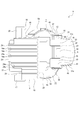
- FIG. 2 to 10 show an embodiment of the present invention, and this figure is a cross-sectional view of a vehicle lamp. It is a top view of the lamp unit. It is one side view of the lamp unit. It is a rear view of a lamp unit. It is the other side view of the lamp unit. It is sectional drawing of the lamp unit. It is an exploded perspective view of a projection lens, a protector, and a lens holder. It is a perspective view of a projection lens, a protector, and a lens holder. It is sectional drawing which shows the positional relationship of a cooling fan and a lamp unit. It is sectional drawing which shows the state which the sunlight is incident on the projection lens.
- the vehicle lighting device 1 is, for example, a vehicle headlight, and is attached and arranged at both left and right ends of the front end of the vehicle body, respectively.
- the vehicle lamp 1 includes a lamp housing 2 having an opening at the front end and a cover 3 attached to the lamp housing 2 with the opening of the lamp housing 2 closed (see FIG. 1).
- the lamp housing 2 and the cover 3 constitute a lamp outer housing 4.
- the internal space of the lamp outer casing 4 is formed as an arrangement space 4a.
- a cooling fan 5 is attached to the lamp housing 2.
- the cooling fan 5 has a function of taking in external air into the arrangement space 4a and cooling each part arranged in the arrangement space 4a.
- the lamp unit 6 is arranged in the arrangement space 4a.
- the lamp unit 6 has a lens holder 7, a heat sink 8, a projection lens 9, a protector 10, and a reflector block 11 (see FIGS. 2 to 6).
- the lens holder 7 has a frame-shaped lens holding portion 12 in which each portion is integrally formed of a resin material and has an axial direction in the front-rear direction, and a substantially U-shape that protrudes rearward from the lens holding portion 12 and opens forward. It has a mounting portion 13 formed in (see FIG. 7).
- the lens holding portion 12 has an upper portion 14 and a lower portion 15 extending in the left-right direction and side portions 16 and 16 located apart from each other in the left-right direction, and the side portions 16 and 16 are gently convex outward in the left-right direction. It is formed in a substantially arc shape. Positioning pins 12a, 12a, 12a projecting forward are provided on the lens holding portion 12 so as to be separated in the circumferential direction.
- Regulatory walls 14a, 14a protruding upward are provided on the upper portion 14 so as to be separated from each other on the left and right.
- a mounting protrusion 14b projecting upward is provided on the upper portion 14 between the regulation walls 14a and 14a.
- the lower portion 15 is provided with a downwardly protruding regulation wall 15a at a substantially central portion in the left-right direction.
- Mounting protrusions 15b and 15b protruding downward are provided on the left and right sides of the regulation wall 15a on the lower portion 15.
- Positioning protrusions 15c and 15c protruding downward are provided on the lower portion 15 on the outside of the mounting protrusions 15b and 15b in the left-right direction.
- the mounting portion 13 protrudes rearward from a position closer to one end in the left-right direction of the lens holding portion 12, and has mounting holes 13a and 13a.
- the mounting holes 13a and 13a are penetrated to the left and right and are positioned vertically separated from each other.
- the heat sink 8 has an optical axis adjusting base 17 and a substrate mounting base 18, and each part is integrally formed of a metal material having high heat dissipation (see FIGS. 2 to 5).
- the optical axis adjusting base 17 has a continuous portion 19 extending vertically, an upper connecting portion 20 projecting laterally from the upper end portion of the continuous portion 19, and a lower connecting portion 21 projecting laterally from the lower end portion of the continuous portion 19.
- the upper connecting portion 20 and the flow regulating portion 22 projecting downward from the tip end portion of the upper connecting portion 20 are provided, and the protruding directions of the upper connecting portion 20 and the lower connecting portion 21 from the continuous portion 19 are the same.
- An upper connecting hole 20a penetrated in the front-rear direction is formed at the end of the upper connecting portion 20 on the continuous portion 19 side.
- An upper and lower aiming screw (not shown) is inserted and connected to the upper connecting hole 20a, and the rear end portion of the upper and lower aiming screw is rotatably supported by the lamp housing 2.
- a lower connecting hole 21a penetrated in the front-rear direction is formed at the tip of the lower connecting portion 21.
- the left and right aiming screws (not shown) are connected to the lower connecting hole 21a in a state of being inserted, and the rear end portion of the left and right aiming screws is rotatably supported by the lamp housing 2.
- a pivot connecting hole 21b is formed at the end of the lower connecting portion 21 on the continuous portion 19 side.
- a pivot shaft (not shown) is connected to the pivot connection hole 21b, and the rear end of the pivot shaft is supported by the lamp housing 2.
- the entire lamp unit 6 including the heat sink 8 is tilted vertically with the pivot axis as a fulcrum to perform vertical aiming, and the left and right aiming screws rotate in the axial direction. Then, the entire lamp unit 6 including the heat sink 8 is tilted in the left-right direction with the pivot axis as a fulcrum, and left-right aiming is performed.
- the board mounting base 18 has a plate-shaped base portion 23 facing in the left-right direction and heat-dissipating fins 24, 24, ... Protruding sideways from the base portion 23 and positioned side by side.
- the rear end portion of the base portion 23 is continuous with the continuous portion 19.
- the circuit board 25 is attached to the surface of the base portion 23 opposite to the side where the heat radiation fins 24, 24, ... Are located.
- Light sources 26, 26, ... are mounted on the circuit board 25 side by side in the vertical direction.
- a light emitting diode LED: Light Emitting Diode
- the light sources 26, 26, ... are individually turned on and off.
- the heat radiating fins 24, 24, ... are projected from the base portion 23 in the direction opposite to the protruding direction from the continuous portion 19 of the upper connecting portion 20, and the thickness directions are aligned in the vertical direction.
- the heat radiating fins 24 are formed as maximum heat radiating surfaces 24a and 24a having the largest areas on both the upper and lower sides.
- the heat sink 8 is attached to the attachment portion 13 of the lens holder 7. Specifically, the upper and lower ends of the front end of the base portion 23 are attached by mounting screws 100 and 100 that are inserted into the mounting holes 13a and 13a, respectively.
- the projection lens 9 has a main body 27 that controls the light emitted from the light sources 26, 26, ..., And an overhang 28 that projects outward from a portion other than a part at the rear end of the main body 27.
- the outer surface of the main body 27 includes an incident surface 29 on which the light emitted from the light sources 26, 26, ... Is incident, an exit surface 30 on which the incident light is emitted, and an outer peripheral surface 31 composed of a plurality of surface portions. It is composed of.
- the incident surface 29 is formed as a surface facing substantially rearward.
- the exit surface 30 is a surface located on the front side, and is formed in a substantially arcuate surface shape that is convex forward.
- the outer peripheral surface 31 is composed of an upper surface portion 31a, a side surface portion 31b, and a lower surface portion 31c in that order in the circumferential direction.
- the side surface portion 31b is formed as a surface facing inward in the left-right direction of the vehicle.
- the upper surface portion 31a and the lower surface portion 31c are formed with, for example, grain, and the side surface portion 31b is formed with, for example, a grain and a step. However, steps may be formed on the upper surface portion 31a and the lower surface portion 31c in addition to the grain.
- the overhanging portion 28 projects outward from the rear end portion of the outer peripheral surface 31, and is formed in a substantially U shape that opens laterally.
- the overhanging portion 28 is formed with hole-shaped or notched-shaped positioning portions 28a, 28a, 28a separated in the circumferential direction.
- the projection lens 9 is attached to the lens holding portion 12 and held by the lens holder 7.
- the projection lens 9 is attached to the lens holding portion 12 in a state where the positioning pins 12a, 12a, 12a are inserted into the positioning portions 28a, 28a, 28a, respectively, and the projection lens 9 is positioned with respect to the lens holder 7. This is done by, for example, adhering or welding the rear surface of the protrusion 28 to the front surface of the lens holding portion 12.
- the protector 10 is formed by a frame-shaped portion 32 penetrating in the front-rear direction and predetermined portions protruding rearward or forward from the frame-shaped portion 32, for example, integrally formed of a metal material (see FIG. 7).
- the entire protector 10 is, for example, black.
- the frame-shaped portion 32 is formed in a plate shape facing in the front-rear direction, and is formed in a size and shape corresponding to the lens holding portion 12 of the lens holder 7.
- the frame-shaped portion 32 has an upper portion 33 and a lower portion 34 extending in the left-right direction, respectively, and side portions 35, 35 located separated from each other to the left and right, and the side portions 35, 35 are outward in the left-right direction. It is formed in a roughly arcuate shape with a gentle convexity.
- the upper positioning pieces 36 and 36 and the upper attached piece 37 are projected rearward, respectively.
- the upper positioning pieces 36, 36 are positioned apart from each other on the left and right, and the upper mounted piece 37 is located between the upper positioning pieces 36, 36.
- the upper mounting piece 37 is formed with mounting holes 37a penetrating vertically.
- the upper positioning pieces 36, 36 and the upper mounted piece 37 are elastically deformable in a direction of being vertically displaced with respect to the frame-shaped portion 32.
- the lower positioning piece 38 and the lower attached pieces 39, 39 are projected rearward, respectively.
- the lower positioning piece 38 projects rearward from the substantially central portion in the left-right direction of the lower portion 34, and the lower mounted pieces 39, 39 are located on the left and right sides of the lower positioning piece 38.
- the lower mounting pieces 39, 39 are formed with mounting holes 39a, 39a that are vertically penetrated.
- the lower positioning piece 38 and the lower mounted pieces 39, 39 are elastically deformable in a direction of being vertically displaced with respect to the frame-shaped portion 32.
- the shading piece 40 protrudes forward from the upper edge of the lower portion 34.
- the light-shielding piece 40 is formed in substantially the same shape as the lower surface portion 31c of the projection lens 9, has the same size as the lower surface portion 31c, or is one size smaller than the lower surface portion 31c. However, the light-shielding piece 40 may be formed in the same shape and size as the lower surface portion 31c.
- Projecting pieces 41 and 41 and holding pieces 42 project rearward from the outer edge of one side portion 35, respectively.
- the projecting pieces 41 and 41 are vertically separated from each other, and the pressing piece 42 is located between the projecting pieces 41 and 41.
- the holding piece 42 is elastically deformable in a direction of being displaced to the left and right with respect to the frame-shaped portion 32.
- the protector 10 is attached to the lens holding portion 12 in a state where the projection lens 9 is attached to the lens holding portion 12 of the lens holder 7 (see FIG. 8).
- the mounting protrusion 14b is inserted into the mounting hole 37a of the upper mounting piece 37, and the mounting protrusions 15b and 15b are inserted into the mounting holes 39a and 39a of the lower mounted pieces 39 and 39, respectively. It is attached to the lens holding portion 12.
- the tips of the upper positioning pieces 36 and 36 are abutted against the front surfaces of the regulation walls 14a and 14a, respectively, and the tips of the lower positioning pieces 38 are abutted against the front surface of the regulation wall 15a so that the protector 10 is front and rear with respect to the lens holder 7.
- Positioning in the direction is performed. Further, a part of the lower mounted pieces 39, 39 is engaged with the positioning protrusions 15c and 15c, respectively, and the pressing piece 42 is pressed against the side portion 16 from the side, so that the protector 10 is laterally oriented with respect to the lens holder 7. Positioning is performed in.
- the overhanging portion 28 of the projection lens 9 is shielded from the front side by the frame-shaped portion 32, and the lower surface portion 31c of the projection lens 9 is shielded from the lower side by the light shielding piece 40. (See FIGS. 2, 3 and 5). Therefore, the lower surface portion 31c of the projection lens 9 is a covered surface portion covered from below by the light-shielding piece 40.
- the protector 10 has a shielding function of shielding a part of the structure arranged in the arrangement space 4a, and the appearance of the vehicle lamp 1 when the vehicle lamp 1 is visually recognized from the front by the protector 10 can be improved.
- the light-shielding piece 40 When the protector 10 is attached to the lens holding portion 12, the light-shielding piece 40 is located below the lower surface portion 31c with a slight gap between the protector 10 and the lower surface portion 31c.
- the reflector block 11 has a case 43, a motor 44, a rotary reflector 45, and a shade 46 (see FIGS. 2 to 6).
- the case 43 has a substantially annular base surface portion 47 and a peripheral surface portion 48 protruding from the outer peripheral portion of the base surface portion 47, and the central hole of the base surface portion 47 is formed as a shaft insertion hole 47a.
- the peripheral surface portion 48 is provided with coupling protrusions 48a, 48a, ... Protruding outwardly, separated from each other in the circumferential direction.
- the case 43 is arranged so that the base surface portion 47 faces diagonally sideways.
- a motor board 49 is attached to the back surface of the base surface portion 47.
- the motor 44 has a motor body 44a and a motor shaft 44b, the motor body 44a is attached to the motor board 49 from the back side, and a part of the motor shaft 44b has a shaft insertion hole 47a of the motor board 49 and the base surface portion 47. It is inserted and located inside the case 43.
- the rotary reflector 45 is fixed to the motor shaft 44b and rotated inside the case 43.
- the rotation reflector 45 has a rotation fulcrum portion 50 that functions as a rotation fulcrum and a reflection portion 51 located on the outer peripheral side of the rotation fulcrum portion 50, and the rotation fulcrum portion 50 is fixed to the motor shaft 44b.
- the surface of the reflection portion 51 opposite to the base surface portion 47 is formed as the reflection control surface 51a, and is slightly inclined with respect to the rotation axis direction of the rotation reflector 45.
- the shade 46 is formed by bending a flat metal material into a predetermined shape, and is orthogonal to the shielding plate portion 52 from the outer peripheral portion of the shielding plate portion 52 and the shielding plate portion 52 that covers the portion of the rotary reflector 45 excluding a part. It has connecting pieces 53, 53, ... Protruding in the same direction. A light passing hole 52a is formed in the shielding plate portion 52.
- the coupling piece portions 53, 53, ... Are elastically deformable with respect to the shielding plate portion 52 in the thickness direction, and the coupling piece portions 53, 53, ... Are formed with coupling holes 53a, 53a, ... Has been done.
- the shade 46 is attached to the case 43 by inserting the coupling protrusions 48a, 48a, ... In the coupling holes 53a, 53a, ..., Respectively.
- the light passing holes 52a are located on the sides of the light sources 26, 26, ..., And the portion excluding a part of the rotary reflector 45 is covered by the shielding plate portion 52.
- the reflector block 11 is attached to the upper connecting portion 20 and the lower connecting portion 21 of the heat sink 8 via mounting sheet metals 54 and 54 (see FIGS. 2 to 4). Part of the mounting sheet metal 54, 54 was coupled to the case 43, and the other part was coupled to the upper connecting portion 20 and the lower connecting portion 21, respectively, and was coupled to the upper connecting portion 20 and the lower connecting portion 21. Each portion is attached by screw members 200, 200. Therefore, the reflector block 11 is attached to the upper connecting portion 20 and the lower connecting portion 21 by the screw members 200, 200 via the mounting sheets 54, 54.
- the light emitted from the light sources 26, 26, ... Is passed through the light passing hole 52a and is rotated by the reflecting portion 51 of the rotating reflector 45. Is reflected and scanned by the reflection control surface 51a.
- the light reflected by the reflecting unit 51 passes through the light passing hole 52a again, is incident on the projection lens 9 from the incident surface 29, is controlled by the projection lens 9 so as to be substantially parallel light, is transmitted through the cover 3, and is forward. It is irradiated toward.
- a part of the light emitted from the light sources 26, 26, ... Is shielded by the shielding plate portion 52 of the shade 46, so that the light transmitted through the cover 3 and irradiated forward is more appropriate.
- a light distribution pattern is formed.
- the light sources 26, 26, ... are individually turned on and off.
- an oncoming vehicle, a preceding vehicle, or a pedestrian is detected by a detection unit (not shown).
- a detection unit not shown.
- the predetermined light source 26 is turned off so that the light toward the oncoming vehicle, the preceding vehicle, or the pedestrian is not emitted.
- An extension 55 is arranged in the arrangement space 4a of the lamp outer casing 4 (see FIGS. 9 and 10).
- the extension 55 is arranged so as to shield a portion of the lamp unit 6 other than the exit surface 30 from the surroundings.
- the rotary reflector 45 is positioned away from the projection surface A in the axial direction P of the cooling fan 5, and at least a part of the heat sink 8 is positioned so as to overlap the projection surface A. It is configured to exist (see FIG. 9).
- the heat sink 8 exists at a position where at least the heat radiation fins 24, 24, ... Are overlapped with the projection surface A.
- the axial direction P of the cooling fan 5 and the axial direction Q of the rotary reflector 45 are in the same direction or substantially the same direction.
- the rotary reflector 45 When the light sources 26, 26, ... Are lit, the rotary reflector 45 is rotated and the light is reflected by the reflecting unit 51 toward the projection lens 9, and at the same time, the cooling fan 5 is rotated and taken in from the outside of the vehicle lamp 1. The air is sent to the lamp unit 6 as cooling air.
- the rotary reflector 45 since the rotary reflector 45 is located away from the projection surface A in the axial direction P of the cooling fan 5, it is difficult for the cooling air to flow toward the rotary reflector 45 and to the heat sink 8. It is easy to flow toward. Further, also because the axial direction P of the cooling fan 5 and the axial direction Q of the rotary reflector 45 are in the same direction or substantially the same direction, the cooling air generated by the cooling fan 5 is flowed toward the rotary reflector 45. hard.
- a flow control unit 22 provided as a part of the heat sink 8 is located between the cooling fan 5 and the rotary reflector 45. Therefore, since the flow regulating unit 22 regulates the flow of the cooling air generated by the cooling fan 5 toward the rotary reflector 45, the cooling air generated by the cooling fan 5 is more difficult to flow toward the rotary reflector 45. ing.
- the flow direction of the cooling air generated by the cooling fan 5 and the flow direction of the air generated by the rotation of the rotary reflector 45 are opposite to each other, and the cooling air generated by the cooling fan 5 is rotated when the rotary reflector 45 is rotated. It is made difficult to be sucked by the rotary reflector 45.
- the heat radiation fins 24, 24, ... Are the maximum heat radiation surfaces 24a, 24a, ... On both the upper and lower sides, which are parallel to or substantially parallel to the axial direction P of the cooling fan 5.
- the cooling air generated by the cooling fan 5 is flowed in a direction parallel to the maximum heat dissipation surfaces 24a, 24a, ....
- the rotary reflector 45 is positioned away from the projection surface A in the axial direction P of the cooling fan 5, and at least a part of the heat sink 8 overlaps the projection surface A.
- the flow direction of the cooling air generated by the cooling fan 5 and the flow direction of the air generated by the rotation of the rotary reflector 45 are opposite to each other.
- the cooling air generated by the cooling fan 5 is less likely to be sucked by the rotation reflector 45 when the rotation reflector 45 is rotated, and the cooling air is less likely to affect the rotation of the rotation reflector 45, so that the rotation reflector 45 is more stably rotated. Can be secured.
- the heat radiation fins 24, 24, ... are formed as maximum heat radiation surfaces 24a, 24a, ... With the largest area on both sides in the thickness direction, and the maximum heat radiation surfaces 24a, 24a, ... Are cooled. It is parallel to the axial direction of the fan 5.
- the heat sink 8 is provided with a flow regulation unit 22 that regulates the flow of the cooling air generated by the cooling fan 5 toward the rotary reflector 45.
- a lamp unit having a projection lens for controlling light emitted from a light source and a lens holder for holding the projection lens is arranged inside a lamp outer housing composed of a lamp housing and a cover.
- a projection lens for controlling light emitted from a light source
- a lens holder for holding the projection lens
- the light emitted from the light source is controlled by a projection lens so as to be parallel light, and is transmitted through the cover and irradiated forward.
- Such a vehicle lamp is provided with a flange-shaped overhang at the rear end of the projection lens, and the overhang is attached to the lens holder to hold the projection lens in the lens holder.
- the overhanging portion is blocked by a predetermined member (see, for example, Japanese Patent Application Laid-Open No. 2017-22032).
- a first member and a second member are provided as a lens holder, an overhanging portion is attached to the first member, and the second member is an overhanging portion. It is configured to be attached to the first member while covering the lens. Therefore, the second member functions as a protector that covers the overhanging portion that is a part of the projection lens, and the overhanging portion is covered by the protector to ensure a good appearance when the vehicle lamp is visually recognized from the front. The visibility is improved.
- the condensed portion is melted, especially when the amount of incident sunlight is large. Or deformation may occur.
- the member of the condensing portion is made of a resin material, such a defect is likely to occur.
- the lamp unit is a part that has a main configuration in vehicle lamps, and it is desirable that the lamp unit is composed of a small number of parts to reduce the manufacturing cost.
- the sunlight S transmitted through the cover 3 may be incident from the exit surface 30 which is not shielded by the extension 55 (see FIG. 10).
- the sunlight S may be internally reflected by the incident surface 29 and reach the lower surface portion 31c depending on the angle of incidence on the projection lens 9.
- the lower surface portion 31c of the projection lens 9 is formed as a covering surface portion, and the protector 10 is provided with a light-shielding piece 40 that covers at least a part of the lower surface portion 31c.
- the lower surface portion 31c of the projection lens 9 is a covered surface portion covered with the light-shielding piece 40, at least one of the surface portions other than the lower surface portion 31c of the outer peripheral surface 31 of the projection lens 9 is shown above.
- the protector 10 may be provided with a light-shielding piece that is formed as a covered surface portion and covers at least a part of the covered surface portion.
- the lower surface portion 31c of the projection lens 9 is formed as a covering surface portion, the surface portion easily reachable by the sunlight S is covered by the light-shielding piece 40, so that the incident direction of the sunlight S with respect to the projection lens 9 is taken into consideration. It is possible to efficiently prevent melting and deformation due to sunlight S.
- the light-shielding piece 40 since the size of the light-shielding piece 40 is smaller than the size of the covering surface portion, the light-shielding piece 40 can be positioned so as not to protrude to the outside of the projection lens 9, and other structures of the light-shielding piece 40 can be positioned. It is possible to prevent melting due to sunlight S while avoiding contact with an object.
- the light-shielding piece 40 may be made larger than the covering surface portion as long as contact with other structures can be avoided.
- the lower surface portion 31c which is the covering surface portion is prevented from being damaged. can do.
- the projection lens 9 is easily visible from diagonally above the front, and the upper surface of the light-shielding piece 40 is easily visible through the projection lens 9.
- the lower surface portion 31c has at least a grain or a step. One is formed. Therefore, the external light incident on the projection lens 9 and reaching the lower surface portion 31c is diffused by the grain or the step, and the light-shielding piece 40 becomes difficult to see through the projection lens 9, and the visibility can be improved.
Landscapes
- Engineering & Computer Science (AREA)
- General Engineering & Computer Science (AREA)
- Physics & Mathematics (AREA)
- Microelectronics & Electronic Packaging (AREA)
- Optics & Photonics (AREA)
- Non-Portable Lighting Devices Or Systems Thereof (AREA)
Abstract
開口を有するランプハウジング2とランプハウジングに開口を閉塞した状態で取り付けられたカバー3とによって構成され内部空間が配置空間4aとして形成された灯具外筐4と、ランプハウジングに取り付けられた冷却ファン5と、配置空間に配置された灯具ユニット6とを備え、灯具ユニットは光源26から出射された光を反射する回転リフレクター45と回転リフレクターを回転させるモーター44と光源の駆動時に発生する熱を放出するヒートシンク8とを有し、回転リフレクターが冷却ファンの軸方向Pにおける投影面Aから離隔して位置され、ヒートシンクの少なくとも一部が投影面に重なる位置に存在する。
Description
本発明は光源から出射された光を反射する回転リフレクターを有する車輌用灯具についての技術分野に関する。
車輌用灯具には、ランプハウジングとカバーによって構成された灯具外筐の内部に光源から出射された光を反射する回転リフレクターと光源の駆動時に発生する熱を放出するヒートシンクとを有し、ヒートシンク等へ向けて冷却ファンにより発生する冷却風が吹き付けられるものがある(例えば、特許文献1参照)。
このような車輌用灯具においては、光源から出射された光が回転リフレクターで反射され、光が回転リフレクターによって走査されて外部へ向けて照射され所定の配光パターンが形成される。光源の駆動時(点灯時)には光源や光源が搭載されている回路基板等において熱が発生するが、発生した熱がヒートシンクに伝達されて放出されると共にヒートシンク等へ向けて冷却ファンにより発生する冷却風が吹き付けられる。従って、光源や回路基板の温度上昇が抑制され、光源や回路基板の安定した駆動状態が確保される。
ところで、上記のような冷却ファンとヒートシンクが設けられた車輌用灯具においては、光源等に対する冷却効率が高くなり光源や回路基板の安定した駆動状態が確保されるが、冷却ファンによって発生する冷却風が回転リフレクターへ向けて流動されると、冷却風が回転リフレクターの回転に影響を及ぼし回転リフレクターの回転動作に支障を来すおそれがある。
そこで、本発明車輌用灯具は、光源の安定した駆動状態を確保した上で回転リフレクターの良好な回転動作を確保することを目的とする。
第1に、本発明に係る車輌用灯具は、開口を有するランプハウジングと前記ランプハウジングに前記開口を閉塞した状態で取り付けられたカバーとによって構成され内部空間が配置空間として形成された灯具外筐と、前記ランプハウジングに取り付けられた冷却ファンと、前記配置空間に配置された灯具ユニットとを備え、前記灯具ユニットは光源から出射された光を反射する回転リフレクターと前記回転リフレクターを回転させるモーターと前記光源の駆動時に発生する熱を放出するヒートシンクとを有し、前記回転リフレクターが前記冷却ファンの軸方向における投影面から離隔して位置され、前記ヒートシンクの少なくとも一部が前記投影面に重なる位置に存在するものである。
これにより、冷却ファンによって発生する冷却風が回転リフレクターへ向けて流動され難いと共にヒートシンクへ向けて冷却風が流動され易くなる。
第2に、上記した本発明に係る車輌用灯具においては、前記冷却ファンの軸方向と前記回転リフレクターの軸方向とが同じ方向にされることが望ましい。
これにより、冷却ファンの中心軸と回転リフレクターの中心軸とが交差しない。
第3に、上記した本発明に係る車輌用灯具においては、前記冷却ファンによって発生する冷却風の流動方向と前記回転リフレクターの回転に伴って発生する風の流動方向とが反対方向にされることが望ましい。
これにより、冷却ファンによって発生する冷却風が回転リフレクターの回転時に回転リフレクターによって吸い込まれ難くなる。
第4に、上記した本発明に係る車輌用灯具においては、前記灯具ユニットに光源が搭載された回路基板が設けられ、前記ヒートシンクに前記回路基板が配置されたベース部と前記ベース部から突出され並んで位置された複数の放熱フィンとが設けられ、前記放熱フィンは厚み方向における両面が最も大きな面積にされた最大放熱面として形成され、前記最大放熱面が前記冷却ファンの軸方向に平行にされることが望ましい。
これにより、冷却ファンによって生じる冷却風が最大放熱面に平行な方向へ流動される。
第5に、上記した本発明に係る車輌用灯具においては、前記ヒートシンクには前記冷却ファンによって発生する冷却風の前記回転リフレクターへ向けての流動を規制する流動規制部が設けられることが望ましい。
これにより、専用の部材を設けて冷却風の回転リフレクターへ向けての流動を規制する必要がない。
第6に、本発明に係る別の灯具ユニットは、光源から出射された光が入射される入射面と前記入射面から入射された光が出射される出射面と複数の面部によって構成された外周面とを有する投影レンズと、前記投影レンズを保持するレンズホルダーと、前記レンズホルダーに取り付けられるプロテクターとを備え、前記複数の面部のうち少なくとも一つが被覆面部として形成され、前記プロテクターに前記被覆面部の少なくとも一部を覆う遮光片が設けられたものである。
これにより、プロテクターに設けられた遮光片によって投影レンズにおける被覆面部の少なくとも一部が覆われる。
第7に、上記した本発明に係る別の灯具ユニットにおいては、前記被覆面部と前記遮光片の間に隙間が形成されることが望ましい。
これにより、被覆面部に遮光片が接触しない。
第8に、上記した本発明に係る別の灯具ユニットにおいては、前記被覆面部にシボ又はステップが形成されることが望ましい。
これにより、投影レンズに入射されて被覆面部に達した外光がシボ又はステップによって拡散される。
第9に、上記した本発明に係る別の灯具ユニットにおいては、前記遮光片の大きさが前記被覆面部の大きさ以下にされることが望ましい。
これにより、遮光片を投影レンズの外側に突出しない状態で位置させることが可能になる。
第10に、上記した本発明に係る別の灯具ユニットにおいては、前記投影レンズの下面部が前記被覆面部として形成されることが望ましい。
これにより、太陽光の達し易い面部が遮光片によって覆われる。
本発明によれば、冷却ファンによって発生する冷却風が回転リフレクターへ向けて流動され難いと共にヒートシンクへ向けて冷却風が流動され易くなるため、ヒートシンクからの熱の放出効率が高くなると共に冷却ファンによって発生する冷却風が回転リフレクターの回転に影響を及ぼし難くなり、光源の安定した駆動状態を確保した上で回転リフレクターの良好な回転動作を確保することができる。
以下に、本発明を実施するための形態について添付図面を参照して説明する。
車輌用灯具1は、例えば、車輌用前照灯であり、それぞれ車体の前端部における左右両端部に取り付けられて配置されている。
車輌用灯具1は、前端に開口を有するランプハウジング2とランプハウジング2の開口を閉塞した状態でランプハウジング2に取り付けられたカバー3とを備えている(図1参照)。ランプハウジング2とカバー3によって灯具外筐4が構成されている。灯具外筐4の内部空間は配置空間4aとして形成されている。
ランプハウジング2には冷却ファン5が取り付けられている。冷却ファン5は外部の空気を配置空間4aに取り込んで配置空間4aに配置される各部を冷却する機能を有している。
配置空間4aには灯具ユニット6が配置されている。灯具ユニット6はレンズホルダー7とヒートシンク8と投影レンズ9とプロテクター10とリフレクターブロック11を有している(図2乃至図6参照)。
レンズホルダー7は、例えば、樹脂材料によって各部が一体に形成され、軸方向が前後方向にされた枠状のレンズ保持部12とレンズ保持部12から後方に突出され前方に開口する略コ字状に形成された取付部13とを有している(図7参照)。
レンズ保持部12はそれぞれ左右方向に延びる上部14及び下部15と左右に離隔して位置された側部16、16とを有し、側部16、16は左右方向において外方に凸の緩やかな略円弧状に形成されている。レンズ保持部12には前方に突出された位置決めピン12a、12a、12aが周方向に離隔して設けられている。
上部14には上方に突出された規制壁14a、14aが左右に離隔して設けられている。上部14には上方に突出された取付突部14bが規制壁14a、14a間に設けられている。
下部15には下方に突出された規制壁15aが左右方向における略中央部に設けられている。下部15には下方に突出された取付突部15b、15bが規制壁15aの左右に設けられている。下部15には下方に突出された位置決め突部15c、15cが左右方向において取付突部15b、15bの外側に設けられている。
取付部13はレンズ保持部12の左右方向における一端寄りの位置から後方に突出され、取付孔13a、13aを有している。取付孔13a、13aは左右に貫通され上下に離隔して位置されている。
ヒートシンク8は光軸調整用ベース17と基板取付用ベース18を有し、放熱性の高い金属材料によって各部が一体に形成されて成る(図2乃至図5参照)。
光軸調整用ベース17は上下に延びる連続部19と連続部19の上端部から側方に突出された上側連結部20と連続部19の下端部から側方に突出された下側連結部21と上側連結部20の先端部から下方に突出された流動規制部22とを有し、上側連結部20と下側連結部21の連続部19からの突出方向が同じにされている。
上側連結部20における連続部19側の端部には前後に貫通された上側連結孔20aが形成されている。上側連結孔20aには図示しない上下用エイミングスクリューが挿通された状態で連結され、上下用エイミングスクリューは後端部がランプハウジング2に回転可能に支持されている。
下側連結部21の先端部には前後に貫通された下側連結孔21aが形成されている。下側連結孔21aには図示しない左右用エイミングスクリューが挿通された状態で連結され、左右用エイミングスクリューは後端部がランプハウジング2に回転可能に支持されている。下側連結部21における連続部19側の端部にはピボット連結孔21bが形成されている。ピボット連結孔21bには図示しないピボット軸が連結され、ピボット軸は後端部がランプハウジング2に支持されている。
上下用エイミングスクリューが軸回り方向へ回転されるとヒートシンク8を含む灯具ユニット6の全体がピボット軸を支点として上下方向へ傾動されて上下エイミングが行われ、左右用エイミングスクリューが軸回り方向へ回転されるとヒートシンク8を含む灯具ユニット6の全体がピボット軸を支点として左右方向へ傾動されて左右エイミングが行われる。
基板取付用ベース18は左右方向を向く板状のベース部23とベース部23から側方に突出され上下に並んで位置された放熱フィン24、24、・・・とを有している。基板取付用ベース18はベース部23の後端部が連続部19に連続されている。
ベース部23の放熱フィン24、24、・・・が位置する側と反対側の面には回路基板25が取り付けられている。回路基板25には上下前後に並んで光源26、26、・・・が搭載されている。光源26としては、例えば、発光ダイオード(LED:Light Emitting Diode)が用いられている。光源26、26、・・・に対しては各別に点消灯制御が行われる。
放熱フィン24、24、・・・は上側連結部20の連続部19からの突出方向と反対方向にベース部23から突出され、厚み方向が上下方向に一致されている。放熱フィン24は上下両面が最も大きな面積にされた最大放熱面24a、24aとして形成されている。
ヒートシンク8はレンズホルダー7の取付部13に取り付けられている。具体的には、ベース部23の前端部における上下両端部がそれぞれ取付孔13a、13aに挿通される取付ネジ100、100によって取り付けられる。
投影レンズ9は光源26、26、・・・から出射された光を制御する本体部27と本体部27の後端部における一部を除いた部分から外方に張り出された張出部28とが、例えば、透明な樹脂材料によって一体に形成されて成る(図2乃至図7参照)。
本体部27の外面は光源26、26、・・・から出射された光が入射される入射面29と入射された光が出射される出射面30と複数の面部によって構成された外周面31とによって構成されている。
入射面29は略後方を向く面として形成されている。出射面30は前側に位置する面であり、前方に凸の略円弧面状に形成されている。
外周面31は上面部31aと側面部31bと下面部31cとが順に周方向において連続して構成されている。側面部31bは車輌の左右方向において内側を向く面として形成されている。上面部31aと下面部31cには、例えば、シボが施され、側面部31bには、例えば、シボとステップが形成されている。但し、上面部31aと下面部31cにもシボに加えステップが形成されていてもよい。
張出部28は外周面31の後端部から外方に張り出され、側方に開口する略コ字状に形成されている。張出部28には穴状又は切欠状の位置決め部28a、28a、28aが周方向に離隔して形成されている。
投影レンズ9はレンズ保持部12に取り付けられてレンズホルダー7に保持される。投影レンズ9のレンズ保持部12への取付は、位置決め部28a、28a、28aにそれぞれ位置決めピン12a、12a、12aが挿入されて投影レンズ9のレンズホルダー7に対する位置決めが行われた状態において、張出部28の後面がレンズ保持部12の前面に、例えば、接着や溶着されることにより行われる。
プロテクター10は前後に貫通された枠状部32と枠状部32から後方又は前方に突出された所定の各部とが、例えば、金属材料によって一体に形成されて成る(図7参照)。プロテクター10は全体が、例えば、黒色にされている。
枠状部32は前後方向を向く板状に形成され、レンズホルダー7のレンズ保持部12に対応した大きさ及び形状に形成されている。枠状部32はそれぞれ左右方向に延びる上方部33及び下方部34と左右に離隔して位置された側方部35、35とを有し、側方部35、35は左右方向において外方に凸の緩やかな略円弧状に形成されている。
上方部33の上縁からはそれぞれ上側位置決め片36、36と上側被取付片37が後方に突出されている。上側位置決め片36、36は左右に離隔して位置され、上側被取付片37は上側位置決め片36、36間に位置されている。上側被取付片37には上下に貫通された被取付孔37aが形成されている。上側位置決め片36、36と上側被取付片37は枠状部32に対して上下に変位する方向へ弾性変形可能にされている。
下方部34の下縁からはそれぞれ下側位置決め片38と下側被取付片39、39が後方に突出されている。下側位置決め片38は下方部34の左右方向における略中央部から後方に突出され、下側被取付片39、39は下側位置決め片38の左右に位置されている。下側被取付片39、39には上下に貫通された被取付孔39a、39aが形成されている。下側位置決め片38と下側被取付片39、39は枠状部32に対して上下に変位する方向へ弾性変形可能にされている。
下方部34の上縁からは遮光片40が前方に突出されている。遮光片40は投影レンズ9の下面部31cと略同じ形状に形成され、下面部31cと同じ大きさ又は下面部31cより一回り小さくされている。但し、遮光片40は下面部31cと同じ形状及び大きさに形成されていてもよい。
一方の側方部35の外縁からはそれぞれ突片41、41と押さえ片42が後方に突出されている。突片41、41は上下に離隔して位置され、押さえ片42は突片41、41間に位置されている。押さえ片42は枠状部32に対して左右に変位する方向へ弾性変形可能にされている。
プロテクター10は投影レンズ9がレンズホルダー7のレンズ保持部12に取り付けられた状態においてレンズ保持部12に取り付けられる(図8参照)。プロテクター10は上側被取付片37の被取付孔37aに取付突部14bが挿入され下側被取付片39、39の被取付孔39a、39aにそれぞれ取付突部15b、15bが挿入されることによりレンズ保持部12に取り付けられる。
このとき上側位置決め片36、36の先端がそれぞれ規制壁14a、14aの前面に突き当てられ下側位置決め片38の先端が規制壁15aの前面に突き当てられることによりプロテクター10のレンズホルダー7に対する前後方向における位置決めが行われる。また、下側被取付片39、39の一部がそれぞれ位置決め突部15c、15cに係合され押さえ片42が側部16に側方から押し当てられることによりプロテクター10のレンズホルダー7に対する左右方向における位置決めが行われる。
プロテクター10がレンズ保持部12に取り付けられた状態においては、枠状部32によって投影レンズ9の張出部28が前側から遮蔽され、投影レンズ9の下面部31cが遮光片40によって下側から遮蔽される(図2、図3及び図5参照)。従って、投影レンズ9の下面部31cは遮光片40によって下方から覆われる被覆面部とされる。
上記のように、プロテクター10がレンズ保持部12に取り付けられた状態において、枠状部32によって投影レンズ9の張出部28が遮蔽され、プロテクター10によって張出部28とレンズ保持部12の結合部分が遮蔽される。従って、プロテクター10は配置空間4aに配置された構造の一部を遮蔽する遮蔽機能を有し、プロテクター10によって車輌用灯具1が前方から視認されたときの見栄えの向上が図られる。
プロテクター10がレンズ保持部12に取り付けられた状態において、遮光片40は下面部31cとの間に僅かな隙間を有した状態で下面部31cの下側に位置される。
リフレクターブロック11はケース43とモーター44と回転リフレクター45とシェード46を有している(図2乃至図6参照)。
ケース43は略円環状のベース面部47とベース面部47の外周部から突出された周面部48とを有し、ベース面部47の中心孔が軸挿通孔47aとして形成されている。周面部48には外方に突出された結合用突部48a、48a、・・・が周方向に離隔して設けられている。ケース43はベース面部47が斜め側方を向く状態で配置されている。ベース面部47の背面にはモーター用基板49が取り付けられている。
モーター44はモーター本体44aとモーター軸44bを有し、モーター本体44aがモーター用基板49に背面側から取り付けられ、モーター軸44bの一部がモーター用基板49及びベース面部47の軸挿通孔47aを挿通されケース43の内部に位置されている。
回転リフレクター45はモーター軸44bに固定されケース43の内部において回転される。回転リフレクター45は回転支点として機能する回転支点部50と回転支点部50の外周側に位置された反射部51とを有し、回転支点部50がモーター軸44bに固定されている。反射部51はベース面部47と反対側の面が反射制御面51aとして形成され、回転リフレクター45の回転軸方向に対して稍傾斜されている。
シェード46は平板状の金属材料が所定の形状に折り曲げられて形成され、回転リフレクター45の一部を除いた部分を覆う遮蔽板部52と遮蔽板部52の外周部から遮蔽板部52に直交する同じ方向に突出された結合片部53、53、・・・とを有している。遮蔽板部52には光通過孔52aが形成されている。結合片部53、53、・・・は厚み方向において遮蔽板部52に対して弾性変形可能にされ、結合片部53、53、・・・には結合孔53a、53a、・・・が形成されている。
シェード46は結合孔53a、53a、・・・にそれぞれ結合用突部48a、48a、・・・が挿入されることによりケース43に取り付けられる。シェード46がケース43に取り付けられた状態においては、光通過孔52aが光源26、26、・・・の側方に位置され、遮蔽板部52によって回転リフレクター45の一部を除いた部分が覆われる。
リフレクターブロック11はヒートシンク8の上側連結部20と下側連結部21に取付用板金54、54を介して取り付けられている(図2乃至図4参照)。取付用板金54、54は一部がそれぞれケース43に結合され他の一部がそれぞれ上側連結部20と下側連結部21に結合され、上側連結部20と下側連結部21に結合された各部分がネジ部材200、200によって取り付けられる。従って、リフレクターブロック11は上側連結部20と下側連結部21に取付用板金54、54を介してネジ部材200、200によって取り付けられる。
上記のように構成された灯具ユニット6において、光源26、26、・・・から出射された光は、一部を除いて光通過孔52aを通過され回転されている回転リフレクター45の反射部51で反射され反射制御面51aによって走査される。反射部51で反射された光は再び光通過孔52aを通過されて入射面29から投影レンズ9に入射され、投影レンズ9によって略平行光になるように制御されてカバー3を透過されて前方へ向けて照射される。このとき光源26、26、・・・から出射された光の一部がシェード46の遮蔽板部52によって遮蔽されることにより、カバー3を透過されて前方へ向けて照射された光により適正な配光パターンが形成される。
光源26、26、・・・から光が出射されるときには光源26、26、・・・や回路基板25において熱が発生し、発生した熱がヒートシンク8に伝達され、主に、放熱フィン24、24、・・・から放出され、光源26、26、・・・や回路基板25の温度上昇が抑制され両者の良好な駆動状態が確保される。このとき放熱フィン24、24、・・・の最大放熱面24a、24a、・・・から最も多くの熱が放出される。
車輌用灯具1においては、上記したように、光源26、26、・・・が各別に点消灯可能にされており、例えば、対向車や先行車や歩行者が図示しない検出部によって検出されたときに、対向車や先行車や歩行者へ向かう光が照射されないように所定の光源26が消灯される制御を行うことが可能にされている。
灯具外筐4の配置空間4aにはエクステンション55が配置されている(図9及び図10参照参照)。エクステンション55は灯具ユニット6の出射面30以外の部分を周囲から遮蔽する状態で配置されている。
上記のように構成された車輌用灯具1においては、回転リフレクター45が冷却ファン5の軸方向Pにおける投影面Aから離隔して位置され、ヒートシンク8の少なくとも一部が投影面Aに重なる位置に存在する構成にされている(図9参照)。例えば、ヒートシンク8は少なくとも放熱フィン24、24、・・・が投影面Aに重なる位置に存在する。また、車輌用灯具1においては、冷却ファン5の軸方向Pと回転リフレクター45の軸方向Qとが同じ方向又は略同じ方向にされている。
光源26、26、・・・の点灯時には回転リフレクター45が回転され光が反射部51で反射されて投影レンズ9へ向かい、同時に、冷却ファン5が回転されて車輌用灯具1の外部から取り込まれた空気が冷却風として灯具ユニット6へ向けて送られる。このとき、上記したように、回転リフレクター45が冷却ファン5の軸方向Pにおける投影面Aから離隔して位置されているため、冷却風が回転リフレクター45へ向けては流動され難いと共にヒートシンク8へ向けては流動され易い。また、冷却ファン5の軸方向Pと回転リフレクター45の軸方向Qとが同じ方向又は略同じ方向にされていることによっても、冷却ファン5によって発生する冷却風が回転リフレクター45へ向けて流動され難い。
また、冷却ファン5と回転リフレクター45の間にはヒートシンク8の一部として設けられた流動規制部22が位置されている。従って、流動規制部22によって冷却ファン5によって発生する冷却風の回転リフレクター45へ向けての流動が規制されるため、冷却ファン5によって発生する冷却風が回転リフレクター45へ向けて一層流動され難くされている。
上記のように、光源26、26、・・・から光が出射されるときには、冷却のために冷却ファン5が回転されると共に光を反射して走査するために回転リフレクター45が回転される。このとき回転リフレクター45の回転に伴って回転リフレクター45の付近に風の流動が生じるが、回転リフレクター45の回転に伴って発生する風は軸方向Qにおいて回転リフレクター45の背面側へ流動するようにされている。
従って、冷却ファン5によって発生する冷却風の流動方向と回転リフレクター45の回転に伴って発生する風の流動方向とは反対方向になり、冷却ファン5によって発生する冷却風が回転リフレクター45の回転時に回転リフレクター45によって吸い込まれ難くされている。
一方、車輌用灯具1において、放熱フィン24、24、・・・は上下両面である最大放熱面24a、24a、・・・が冷却ファン5の軸方向Pに平行又は略平行にされており、冷却ファン5によって生じる冷却風が最大放熱面24a、24a、・・・に平行な方向へ沿って流動される。
以上に記載した通り、車輌用灯具1にあっては、回転リフレクター45が冷却ファン5の軸方向Pにおける投影面Aから離隔して位置され、ヒートシンク8の少なくとも一部が投影面Aに重なる位置に存在する。
従って、冷却ファン5によって発生する冷却風が回転リフレクター45へ向けて流動され難いと共にヒートシンク8へ向けて冷却風が流動され易くなる。これにより、ヒートシンク8からの熱の放出効率が高くなると共に冷却ファン5によって発生する冷却風が回転リフレクター45の回転に影響を及ぼし難くなり、光源26、26、・・・の安定した駆動状態を確保した上で回転リフレクター45の良好な回転動作を確保することができる。
また、冷却ファン5の軸方向Pと回転リフレクター45の軸方向Qとが同じ方向にされているため、冷却ファン5の中心軸と回転リフレクター45の中心軸とが交差しない。
従って、冷却ファン5によって発生する冷却風が回転リフレクター45へ向けて流動され難く、回転リフレクター45の安定した回転状態が確保され光源26、26、・・・から出射された光による適正な配光状態を確保することができる。
さらに、冷却ファン5によって発生する冷却風の流動方向と回転リフレクター45の回転に伴って発生する風の流動方向とが反対方向にされている。
従って、冷却ファン5によって発生する冷却風が回転リフレクター45の回転時に回転リフレクター45によって吸い込まれ難くなり、冷却風が回転リフレクター45の回転に影響を及ぼし難く、回転リフレクター45の一層安定した回転状態を確保することができる。
さらにまた、放熱フィン24、24、・・・は厚み方向における両面が最も大きな面積にされた最大放熱面24a、24a、・・・として形成され、最大放熱面24a、24a、・・・が冷却ファン5の軸方向に平行にされている。
従って、冷却ファン5によって生じる冷却風が最大放熱面24a、24a、・・・に平行な方向へ流動されるため、ヒートシンク8の放熱性能の向上を図ることができる。
加えて、ヒートシンク8には冷却ファン5によって発生する冷却風の回転リフレクター45へ向けての流動を規制する流動規制部22が設けられている。
従って、ヒートシンク8の一部によって冷却風の回転リフレクター45へ向けての流動が規制されるため、専用の部材を設けて冷却風の回転リフレクター45へ向けての流動を規制する必要がなく、部品点数の削減を図った上で冷却風の回転リフレクター45の回転に対する影響を抑制することができる。
ところで、車輌用灯具には、ランプハウジングとカバーによって構成された灯具外筐の内部に光源から出射された光を制御する投影レンズと投影レンズを保持するレンズホルダーとを有する灯具ユニットが配置され、光源から出射された光が投影レンズによって平行光になるように制御され、カバーを透過され前方へ向けて照射されるタイプがある。
このような車輌用灯具には投影レンズの後端部に外方に張り出されたフランジ状の張出部が設けられ、張出部がレンズホルダーに取り付けられて投影レンズがレンズホルダーに保持されると共に張出部が所定の部材によって閉塞されるものがある(例えば、特開2017-22032号公報参照)。
上記の文献に記載された車輌用灯具にあっては、レンズホルダーとして第1の部材と第2の部材が設けられ、第1の部材に張出部が取り付けられ第2の部材が張出部を覆う状態で第1の部材に取り付けられる構成にされている。従って、第2の部材は投影レンズの一部である張出部を覆うプロテクターとして機能し、張出部がプロテクターによって覆われることにより車輌用灯具が前方から視認されたときの良好な見栄えが確保され、被視認性の向上が図られる。
上記のような投影レンズを有する灯具ユニットを備えた車輌用灯具においては、カバーを透過される太陽光が投影レンズに入射される可能性がある。太陽光が投影レンズに入射されると、投影レンズに対する入射角度によっては、太陽光が投影レンズで内面反射(全反射)され、投影レンズから灯具外筐の内部に配置された各部材に向かう可能性がある。
このとき投影レンズから出射された太陽光が灯具外筐の内部に配置された各部材において集光されてしまうと、特に、太陽光の入射量が多い場合には、集光された部分の溶融や変形と言う不具合を生じる可能性がある。特に、集光された部分の部材が樹脂材料によって形成されている場合には、このような不具合が生じ易い。
一方、灯具ユニットは車輌用灯具において主要な構成を有する部分であり、少ない部品点数で構成して製造コストの低減が図られることが望ましい。
上記のように構成された車輌用灯具1においては、カバー3を透過される太陽光Sがエクステンション55によって遮蔽されていない出射面30から入射される可能性がある(図10参照)。太陽光Sが投影レンズ9に入射されると、投影レンズ9に対する入射角度によっては太陽光Sが入射面29で内面反射され下面部31cに達するおそれがある。
しかしながら、灯具ユニット6においては、下面部31cが遮光片40によって下側から遮蔽されているため、太陽光Sが下面部31cを透過した場合においても遮光片40によって遮光され、灯具ユニット6の他の部分へ向かい難い。
以上に記載した通り、灯具ユニット6にあっては、投影レンズ9の下面部31cが被覆面部として形成され、プロテクター10に下面部31cの少なくとも一部を覆う遮光片40が設けられている。
従って、プロテクター10に設けられた遮光片40によって投影レンズ9における下面部31cの少なくとも一部が覆われるため、下面部31cを覆う専用の部材が必要なく、部品点数の削減による製造コストの低減を図った上で太陽光Sの投影レンズ9への入射による不具合の発生を防止することができる。
尚、上記には、投影レンズ9の下面部31cが遮光片40によって覆われる被覆面部とされた例を示したが、投影レンズ9における外周面31の下面部31c以外の面部のうち少なくとも一つが被覆面部として形成され、この被覆面部の少なくとも一部を覆う遮光片がプロテクター10に設けられてもよい。
但し、投影レンズ9の下面部31cが被覆面部として形成されていることにより、太陽光Sの達し易い面部が遮光片40によって覆われるため、太陽光Sの投影レンズ9に対する入射方向を考慮して太陽光Sによる溶融や変形を効率的に防止することができる。
また、遮光片40の大きさが被覆面部の大きさ以下にされているため、遮光片40を投影レンズ9の外側に突出しない状態で位置させることが可能になり、遮光片40の他の構造物との接触を回避した上で太陽光Sによる溶融を防止することができる。
但し、遮光片40は他の構造物との接触が回避可能であれば被覆面部より大きくされていてもよい。
また、上記したように、投影レンズ9における外周面31の各部にシボやステップが形成されることにより、投影レンズ9に太陽光が入射されたときにシボやステップによって太陽光が拡散され、太陽光が投影レンズ9を透過しても配置空間4aに配置された各部に集光され難く、配置空間4aに配置された各部の太陽光による溶融や変形が生じ難くされている。また、外周面31の各部にシボやステップが形成されることにより、車輌用灯具1の外部から外周面31を通して配置空間4aに配置された各部が視認され難くなり、被視認性の向上を図ることも可能である。
さらに、上記したように、下面部31cと遮光片40の間に隙間が形成されることにより、下面部31cに遮光片40が接触しないため、被覆面部とされた下面部31cの傷付きを防止することができる。
さらにまた、車輌において投影レンズ9は前斜め上方から視認され易く遮光片40の上面が投影レンズ9を通して視認され易い位置に存在するが、上記したように、下面部31cにはシボ又はステップの少なくとも一方が形成されている。従って、投影レンズ9に入射されて下面部31cに達した外光がシボ又はステップによって拡散され、遮光片40が投影レンズ9を通して見え難くなり、被視認性の向上を図ることができる。
1…車輌用灯具、2…ランプハウジング、3…カバー、4…灯具外筐、4a…配置空間、5…冷却ファン、6…灯具ユニット、7…レンズホルダー、8…ヒートシンク、9…投影レンズ、10…プロテクター、23…ベース部、24…放熱フィン、24a…最大放熱面、25…回路基板、26…光源、29…入射面、30…出射面、31…外周面、31c…下面部、40…遮光片45…回転リフレクター
Claims (10)
- 開口を有するランプハウジングと前記ランプハウジングに前記開口を閉塞した状態で取り付けられたカバーとによって構成され内部空間が配置空間として形成された灯具外筐と、
前記ランプハウジングに取り付けられた冷却ファンと、
前記配置空間に配置された灯具ユニットとを備え、
前記灯具ユニットは光源から出射された光を反射する回転リフレクターと前記回転リフレクターを回転させるモーターと前記光源の駆動時に発生する熱を放出するヒートシンクとを有し、
前記回転リフレクターが前記冷却ファンの軸方向における投影面から離隔して位置され、
前記ヒートシンクの少なくとも一部が前記投影面に重なる位置に存在する
車輌用灯具。 - 前記冷却ファンの軸方向と前記回転リフレクターの軸方向とが同じ方向にされた
請求項1に記載の車輌用灯具。 - 前記冷却ファンによって発生する冷却風の流動方向と前記回転リフレクターの回転に伴って発生する風の流動方向とが反対方向にされた
請求項1又は請求項2に記載の車輌用灯具。 - 前記灯具ユニットに光源が搭載された回路基板が設けられ、
前記ヒートシンクに前記回路基板が配置されたベース部と前記ベース部から突出され並んで位置された複数の放熱フィンとが設けられ、
前記放熱フィンは厚み方向における両面が最も大きな面積にされた最大放熱面として形成され、
前記最大放熱面が前記冷却ファンの軸方向に平行にされた
請求項1、請求項2又は請求項3に記載の車輌用灯具。 - 前記ヒートシンクには前記冷却ファンによって発生する冷却風の前記回転リフレクターへ向けての流動を規制する流動規制部が設けられた
請求項1、請求項2、請求項3又は請求項4に記載の車輌用灯具。 - 光源から出射された光が入射される入射面と前記入射面から入射された光が出射される出射面と複数の面部によって構成された外周面とを有する投影レンズと、
前記投影レンズを保持するレンズホルダーと、
前記レンズホルダーに取り付けられるプロテクターとを備え、
前記複数の面部のうち少なくとも一つが被覆面部として形成され、
前記プロテクターに前記被覆面部の少なくとも一部を覆う遮光片が設けられた
灯具ユニット。 - 前記被覆面部と前記遮光片の間に隙間が形成された
請求項6に記載の灯具ユニット。 - 前記被覆面部にシボ又はステップが形成された
請求項6又は請求項7に記載の灯具ユニット。 - 前記遮光片の大きさが前記被覆面部の大きさ以下にされた
請求項6、請求項7又は請求項8に記載の灯具ユニット。 - 前記投影レンズの下面部が前記被覆面部として形成された
請求項6、請求項7、請求項8又は請求項9に記載の灯具ユニット。
Priority Applications (1)
| Application Number | Priority Date | Filing Date | Title |
|---|---|---|---|
| JP2021542841A JP7433326B2 (ja) | 2019-08-26 | 2020-08-21 | 車輌用灯具及び灯具ユニット |
Applications Claiming Priority (4)
| Application Number | Priority Date | Filing Date | Title |
|---|---|---|---|
| JP2019-154113 | 2019-08-26 | ||
| JP2019-154114 | 2019-08-26 | ||
| JP2019154113 | 2019-08-26 | ||
| JP2019154114 | 2019-08-26 |
Publications (1)
| Publication Number | Publication Date |
|---|---|
| WO2021039633A1 true WO2021039633A1 (ja) | 2021-03-04 |
Family
ID=74685557
Family Applications (1)
| Application Number | Title | Priority Date | Filing Date |
|---|---|---|---|
| PCT/JP2020/031639 Ceased WO2021039633A1 (ja) | 2019-08-26 | 2020-08-21 | 車輌用灯具及び灯具ユニット |
Country Status (2)
| Country | Link |
|---|---|
| JP (1) | JP7433326B2 (ja) |
| WO (1) | WO2021039633A1 (ja) |
Citations (9)
| Publication number | Priority date | Publication date | Assignee | Title |
|---|---|---|---|---|
| JPH01165501U (ja) * | 1988-05-13 | 1989-11-20 | ||
| JP2011082005A (ja) * | 2009-10-07 | 2011-04-21 | Koito Mfg Co Ltd | 車輌用灯具 |
| JP2014063604A (ja) * | 2012-09-20 | 2014-04-10 | Ichikoh Ind Ltd | 車両用灯具 |
| US20140146555A1 (en) * | 2012-11-28 | 2014-05-29 | Sl Corporation | Lamp assembly for vehicle |
| JP2014154253A (ja) * | 2013-02-05 | 2014-08-25 | Koito Mfg Co Ltd | 車輌用灯具 |
| WO2015122303A1 (ja) * | 2014-02-12 | 2015-08-20 | 株式会社小糸製作所 | 光学ユニットおよび車両用灯具 |
| JP2017022032A (ja) * | 2015-07-13 | 2017-01-26 | 市光工業株式会社 | 車両用灯具 |
| JP2019003908A (ja) * | 2017-06-20 | 2019-01-10 | 株式会社小糸製作所 | ランプユニット |
| JP2019505084A (ja) * | 2016-02-02 | 2019-02-21 | ツェットカーヴェー グループ ゲーエムベーハー | 自動車用の照射ユニット |
-
2020
- 2020-08-21 WO PCT/JP2020/031639 patent/WO2021039633A1/ja not_active Ceased
- 2020-08-21 JP JP2021542841A patent/JP7433326B2/ja active Active
Patent Citations (9)
| Publication number | Priority date | Publication date | Assignee | Title |
|---|---|---|---|---|
| JPH01165501U (ja) * | 1988-05-13 | 1989-11-20 | ||
| JP2011082005A (ja) * | 2009-10-07 | 2011-04-21 | Koito Mfg Co Ltd | 車輌用灯具 |
| JP2014063604A (ja) * | 2012-09-20 | 2014-04-10 | Ichikoh Ind Ltd | 車両用灯具 |
| US20140146555A1 (en) * | 2012-11-28 | 2014-05-29 | Sl Corporation | Lamp assembly for vehicle |
| JP2014154253A (ja) * | 2013-02-05 | 2014-08-25 | Koito Mfg Co Ltd | 車輌用灯具 |
| WO2015122303A1 (ja) * | 2014-02-12 | 2015-08-20 | 株式会社小糸製作所 | 光学ユニットおよび車両用灯具 |
| JP2017022032A (ja) * | 2015-07-13 | 2017-01-26 | 市光工業株式会社 | 車両用灯具 |
| JP2019505084A (ja) * | 2016-02-02 | 2019-02-21 | ツェットカーヴェー グループ ゲーエムベーハー | 自動車用の照射ユニット |
| JP2019003908A (ja) * | 2017-06-20 | 2019-01-10 | 株式会社小糸製作所 | ランプユニット |
Also Published As
| Publication number | Publication date |
|---|---|
| JP7433326B2 (ja) | 2024-02-19 |
| JPWO2021039633A1 (ja) | 2021-03-04 |
Similar Documents
| Publication | Publication Date | Title |
|---|---|---|
| JP5879065B2 (ja) | 車両用前照灯 | |
| US8939627B2 (en) | Vehicle lighting unit | |
| US9964276B2 (en) | Illumination device for vehicle having rotatable first shade and one piece component with shades and reflector disposed in front of first shade | |
| JP4270093B2 (ja) | プロジェクタ型車両用前照灯ユニット | |
| JP5806053B2 (ja) | 車両用前照灯 | |
| JP5830294B2 (ja) | 車両用前照灯 | |
| JP6028487B2 (ja) | 車両用灯具 | |
| JP2008153108A (ja) | 車両用灯具 | |
| CN111076136B (zh) | 灯具单元以及车辆用灯具 | |
| CN111279122B (zh) | 车辆用的灯具 | |
| JP7601878B2 (ja) | 車輌用灯具 | |
| JP6511870B2 (ja) | 車両用灯具 | |
| JP2016149373A (ja) | 灯具ユニット | |
| JP5921899B2 (ja) | 灯具ユニット | |
| JP2010262765A (ja) | 車輌用灯具 | |
| CN212644476U (zh) | 车辆用灯具 | |
| JP2020095876A (ja) | 車両用灯具 | |
| WO2021039633A1 (ja) | 車輌用灯具及び灯具ユニット | |
| JP2013045717A (ja) | 車両用灯具 | |
| EP2413024A2 (en) | Illumination device | |
| JP7459643B2 (ja) | 車両用灯具 | |
| CN211345152U (zh) | 车辆用灯具 | |
| CN112432130A (zh) | 灯具单元 | |
| CN211345148U (zh) | 灯具单元 | |
| JP7024424B2 (ja) | 車両用灯具 |
Legal Events
| Date | Code | Title | Description |
|---|---|---|---|
| 121 | Ep: the epo has been informed by wipo that ep was designated in this application |
Ref document number: 20856980 Country of ref document: EP Kind code of ref document: A1 |
|
| ENP | Entry into the national phase |
Ref document number: 2021542841 Country of ref document: JP Kind code of ref document: A |
|
| NENP | Non-entry into the national phase |
Ref country code: DE |
|
| 122 | Ep: pct application non-entry in european phase |
Ref document number: 20856980 Country of ref document: EP Kind code of ref document: A1 |