WO2021033606A1 - プログラム、ゲーム処理方法、及びゲーム装置 - Google Patents
プログラム、ゲーム処理方法、及びゲーム装置 Download PDFInfo
- Publication number
- WO2021033606A1 WO2021033606A1 PCT/JP2020/030690 JP2020030690W WO2021033606A1 WO 2021033606 A1 WO2021033606 A1 WO 2021033606A1 JP 2020030690 W JP2020030690 W JP 2020030690W WO 2021033606 A1 WO2021033606 A1 WO 2021033606A1
- Authority
- WO
- WIPO (PCT)
- Prior art keywords
- game
- region
- user
- unit
- instruction
- Prior art date
- Legal status (The legal status is an assumption and is not a legal conclusion. Google has not performed a legal analysis and makes no representation as to the accuracy of the status listed.)
- Ceased
Links
Images




Classifications
-
- A—HUMAN NECESSITIES
- A63—SPORTS; GAMES; AMUSEMENTS
- A63F—CARD, BOARD, OR ROULETTE GAMES; INDOOR GAMES USING SMALL MOVING PLAYING BODIES; VIDEO GAMES; GAMES NOT OTHERWISE PROVIDED FOR
- A63F13/00—Video games, i.e. games using an electronically generated display having two or more dimensions
- A63F13/40—Processing input control signals of video game devices, e.g. signals generated by the player or derived from the environment
- A63F13/42—Processing input control signals of video game devices, e.g. signals generated by the player or derived from the environment by mapping the input signals into game commands, e.g. mapping the displacement of a stylus on a touch screen to the steering angle of a virtual vehicle
- A63F13/426—Processing input control signals of video game devices, e.g. signals generated by the player or derived from the environment by mapping the input signals into game commands, e.g. mapping the displacement of a stylus on a touch screen to the steering angle of a virtual vehicle involving on-screen location information, e.g. screen coordinates of an area at which the player is aiming with a light gun
-
- A—HUMAN NECESSITIES
- A63—SPORTS; GAMES; AMUSEMENTS
- A63F—CARD, BOARD, OR ROULETTE GAMES; INDOOR GAMES USING SMALL MOVING PLAYING BODIES; VIDEO GAMES; GAMES NOT OTHERWISE PROVIDED FOR
- A63F13/00—Video games, i.e. games using an electronically generated display having two or more dimensions
- A63F13/45—Controlling the progress of the video game
-
- A—HUMAN NECESSITIES
- A63—SPORTS; GAMES; AMUSEMENTS
- A63F—CARD, BOARD, OR ROULETTE GAMES; INDOOR GAMES USING SMALL MOVING PLAYING BODIES; VIDEO GAMES; GAMES NOT OTHERWISE PROVIDED FOR
- A63F13/00—Video games, i.e. games using an electronically generated display having two or more dimensions
- A63F13/50—Controlling the output signals based on the game progress
- A63F13/53—Controlling the output signals based on the game progress involving additional visual information provided to the game scene, e.g. by overlay to simulate a head-up display [HUD] or displaying a laser sight in a shooting game
- A63F13/537—Controlling the output signals based on the game progress involving additional visual information provided to the game scene, e.g. by overlay to simulate a head-up display [HUD] or displaying a laser sight in a shooting game using indicators, e.g. showing the condition of a game character on screen
- A63F13/5375—Controlling the output signals based on the game progress involving additional visual information provided to the game scene, e.g. by overlay to simulate a head-up display [HUD] or displaying a laser sight in a shooting game using indicators, e.g. showing the condition of a game character on screen for graphically or textually suggesting an action, e.g. by displaying an arrow indicating a turn in a driving game
-
- A—HUMAN NECESSITIES
- A63—SPORTS; GAMES; AMUSEMENTS
- A63F—CARD, BOARD, OR ROULETTE GAMES; INDOOR GAMES USING SMALL MOVING PLAYING BODIES; VIDEO GAMES; GAMES NOT OTHERWISE PROVIDED FOR
- A63F13/00—Video games, i.e. games using an electronically generated display having two or more dimensions
- A63F13/55—Controlling game characters or game objects based on the game progress
-
- A—HUMAN NECESSITIES
- A63—SPORTS; GAMES; AMUSEMENTS
- A63F—CARD, BOARD, OR ROULETTE GAMES; INDOOR GAMES USING SMALL MOVING PLAYING BODIES; VIDEO GAMES; GAMES NOT OTHERWISE PROVIDED FOR
- A63F13/00—Video games, i.e. games using an electronically generated display having two or more dimensions
- A63F13/55—Controlling game characters or game objects based on the game progress
- A63F13/58—Controlling game characters or game objects based on the game progress by computing conditions of game characters, e.g. stamina, strength, motivation or energy level
-
- A—HUMAN NECESSITIES
- A63—SPORTS; GAMES; AMUSEMENTS
- A63F—CARD, BOARD, OR ROULETTE GAMES; INDOOR GAMES USING SMALL MOVING PLAYING BODIES; VIDEO GAMES; GAMES NOT OTHERWISE PROVIDED FOR
- A63F13/00—Video games, i.e. games using an electronically generated display having two or more dimensions
- A63F13/70—Game security or game management aspects
- A63F13/79—Game security or game management aspects involving player-related data, e.g. identities, accounts, preferences or play histories
-
- A—HUMAN NECESSITIES
- A63—SPORTS; GAMES; AMUSEMENTS
- A63F—CARD, BOARD, OR ROULETTE GAMES; INDOOR GAMES USING SMALL MOVING PLAYING BODIES; VIDEO GAMES; GAMES NOT OTHERWISE PROVIDED FOR
- A63F13/00—Video games, i.e. games using an electronically generated display having two or more dimensions
- A63F13/80—Special adaptations for executing a specific game genre or game mode
- A63F13/812—Ball games, e.g. soccer or baseball
-
- G—PHYSICS
- G06—COMPUTING OR CALCULATING; COUNTING
- G06F—ELECTRIC DIGITAL DATA PROCESSING
- G06F3/00—Input arrangements for transferring data to be processed into a form capable of being handled by the computer; Output arrangements for transferring data from processing unit to output unit, e.g. interface arrangements
- G06F3/01—Input arrangements or combined input and output arrangements for interaction between user and computer
- G06F3/048—Interaction techniques based on graphical user interfaces [GUI]
- G06F3/0481—Interaction techniques based on graphical user interfaces [GUI] based on specific properties of the displayed interaction object or a metaphor-based environment, e.g. interaction with desktop elements like windows or icons, or assisted by a cursor's changing behaviour or appearance
Definitions
- the present invention relates to a program, a game processing method, and a game device.
- Non-Patent Document 1 For example, in a baseball game, when a fielder moves a fielder in the direction of arrival of the ball in order to catch the ball, an area for specifying the direction in which the fielder should move is displayed, and the success level of the movement operation performed by the user is evaluated. It is known (see, for example, Non-Patent Document 1).
- the fielder in light of the actual play of the fielder, the fielder is required to move in the direction of the hit ball as quickly as possible. Considering this, in the game, it is preferable to require the user to perform the movement operation as soon as possible from the timing when the batter hits the ball, because the interest of the game is enhanced.
- One of an object of the present invention is to provide a program, a game processing method, and a game device capable of realizing a game that requires a user to perform a movement operation at the earliest possible timing. Let's try.
- Another object of the present invention is to provide a program, a game processing method, and a game device capable of exerting the effects described in the embodiments described later.
- One aspect of the present invention for solving the above-mentioned problems is a program executed by a computer included in a device that processes a game based on a user's operation, and is a reception unit that accepts the user's operation and a user.
- a display control unit that displays an object having an indicator that indicates an instruction direction to be operated, and a determination that determines whether the user's operation direction with respect to the instruction direction is included in a predetermined direction range corresponding to the instruction direction.
- the computer is made to function as a unit and a changing unit that gradually reduces the direction range within a reception period in which a user's operation with respect to the instruction direction can be accepted, and the display control unit sets the indicator to the direction range.
- This is a non-temporary storage medium in which a program is stored, in which the display mode is displayed and the display mode of the indicator is changed in accordance with the gradual decrease of the direction range.
- One aspect of the present invention is a game processing method executed by a computer included in a device that processes a game based on a user's operation, and a step of accepting the user's operation and an instruction direction to be operated by the user.
- the directional range is gradually reduced by displaying the indicator in a display mode indicating the directional range in the step of displaying the directional range.
- One aspect of the present invention is a game device that processes a game based on a user's operation, and displays an object having a reception unit that accepts the user's operation and an indicator that indicates an instruction direction to be operated by the user.
- the display control unit includes a changing unit for gradually reducing the direction range, and the display control unit displays the indicator in a display mode indicating the direction range, and the instruction corresponds to the gradual decrease of the direction range. It is a game device that changes the display mode of the child.
- the flowchart which shows an example of the jump ball processing which concerns on 2nd Embodiment.
- the game according to this embodiment is a game played by using a plurality of characters.
- the character is a game character such as a person, an animal, or an object (for example, a vehicle) appearing in the game, and is displayed as an image (character image) on the game screen.
- an example of the game according to the present embodiment is a baseball game including a training part and a competition part.
- the training part is a game part that trains characters corresponding to players. In the training part, the ability of the character can be improved by training the character.
- the battle part is a game part in which a team including a character trained in the training part is used as a player to play a baseball game against the opponent's team.
- FIG. 1 is a diagram showing an example of a home screen.
- the home screen is a screen on which a home image corresponding to the main menu, which is the starting point of this game, is displayed.
- icons P110, P120, P130, P140, P150, P160, P170, and P180 that function as controls for accepting user operations are displayed.
- Each of the icons is associated with a process to be executed in response to the reception of the operation of selecting the icon.
- “Training” is displayed on the icon P110, and processing related to the training part is associated with it.
- the processing of the training part is executed.
- the icon P120 is displayed as "match”, and processing related to the battle part is associated with it.
- the processing of the battle part is executed.
- the icon P130 is displayed as a "character list” and is associated with a character display process for displaying a list of owned characters. The user can acquire and own the character by a lottery process described later. When the icon P130 is selected, the character display process is executed.
- the icon P140 is displayed as "My Team", and is associated with displaying information about the teams trained by the user in the training part and team processing for making various settings for the team.
- team processing is executed.
- the icon P150 is displayed as "lottery” and is associated with a lottery process for determining a character to be acquired by the user by lottery.
- the lottery process is executed.
- the icon P160 is displayed as "shop”, and is associated with a purchase process for purchasing and acquiring an item or the like by consuming game value such as points.
- the purchase process is executed. When the operation to end the game is performed, the game ends.
- “Special” is displayed on the icon P170, and the processing of the special part that can play a specific game that constitutes a part of the game is executed.
- the special part is combined with a game that focuses on a specific element in baseball (for example, a knock practice game) or a game that is not directly related to the rules of baseball (such as bingo). Includes games and more.
- This special part game is a small game (mini game, mini battle) compared to the battle part and the training part.
- the icon P180 is displayed as "Tournament", and the processing of the tournament part to be played in the tournament is associated with it.
- the processing of the tournament part is executed. For example, players are ranked according to the result of playing a knock practice game or the like in the above special part (for example, national ranking), and when they are ranked high in this national ranking, they are given the right to participate in the tournament.
- the special part includes a knock practice game as part of the game.
- the character selected by the user as a training target is made to perform knock practice.
- the user operates a character selected as a training target and plays so as to catch a ball hit by a knocker.
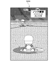
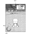
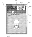
- FIG. 2 shows an example of the game screen G200 of the knock practice game.
- a game space imitating the ground of a baseball field is displayed.
- the fielder character C1 and the knocker character C2 are displayed in the game space.
- the viewpoint for the game space is set so that the knocker character C2 is viewed from behind the fielder character C1.
- a batter box is arranged on the upper side of the game screen G200 and on the back side of the game space, and a defensive area is arranged on the lower side of the game screen G200 and on the front side of the game space.
- the knocker character C2 is displayed above the game screen G200
- the fielder character C1 is displayed below the game screen G200.
- the ball B hit by the knocker character C2 moves from the back side to the front side of the game space, that is, from the direction of the knocker character C2 on the upper side of the game screen G200 to the direction of the field character C1 on the lower side of the game screen G200. Is displayed.
- the game screen G200 is provided with an information presentation area AR10.
- game information related to the knock practice game is displayed.
- game information information indicating that the game is a knock practice game, points earned in the game, and the number of remaining balls in the game are displayed.
- the earned points are points given according to the evaluation of the operation performed by the user to catch the knocked ball B.
- the cumulative value (point cumulative value) of the points given according to the evaluation for each catch so far may be displayed.
- the point cumulative value is given to the fielder character C1, but since the user is operating the fielder character C1, it can be seen as a parameter given to the user.
- the number of remaining balls indicates the remaining number of knocks that can be received from now on, for example, in a knock practice game in which a total of 30 knocks can be received.
- the direction of arrival of the ball B hit by the knocker character C2 is, for example, an arbitrary lateral direction with respect to the front surface of the fielder character C1.
- the direction of arrival of the ball B is determined for each knock, for example, at random.
- the user determines the direction of arrival of the ball B in response to the hit of the ball B by the knocker character C2.
- the user performs an operation (movement operation) for designating the direction in which the fielder character C1 should be moved according to the arrival direction of the ball B.
- the movement operation becomes acceptable in response to the hit of the ball B by the knocker character C2.
- the movement operation is a flick operation on the game screen G200 displayed on the touch panel monitor.
- the movement operation may be other than the flick operation, and may be a swipe operation or a slide operation. That is, any operation means for the movement operation is arbitrary as long as the operation specifies the direction in which the fielder character C1 should be moved.
- the operation starting point of the touch operation such as the flick operation is preferably the position where the fielder character C1 is arranged on the game screen G200, but it may be different from the position where the fielder character C1 is arranged, or the fielder character C1 is arranged. It may be both the position where the position is set and the position different from the position.
- the starting point is the position where the fielder character C1 is arranged. If the touch operation is adopted, the user's touch operation is less likely to block the upper side of the fielder character C1 of the game screen G200, and the user's visibility of the display of the ball B moving in the game space can be improved. As a result, the operability for the game is improved.
- the game screen G200 in the figure shows the timing at which the ball B is knocked by the knocker character C2 in one knock.
- the display of the image G is started.
- the guide image G guides the direction (optimal direction) required to be specified by the movement operation according to the arrival direction of the ball B hit by the knocker character C2.
- the guide image G has a circular (doughnut-shaped) shape in order to make it easy to visually understand the optimum direction centered on the foot of the fielder character C1.
- the guide image G in the figure is displayed in an elliptical shape due to the relationship of the viewpoint with respect to the game space, but is circular when viewed from above with respect to the ground surface.
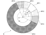
- FIG. 3 is a view of the guide image G arranged on the game screen G200 extracted from above with respect to the ground surface.
- the guide image G includes four regions, that is, a first region AR11, a second region AR12, a third region AR13, and a fourth region AR14 so as to divide the circumference of the ring (doughnut shape).
- the areas are color coded.
- the first region AR11 is color-coded by white
- the second region AR12 is color-coded by yellow
- the third region AR13 is color-coded by green
- the fourth region AR14 is color-coded by red.
- the color coding is schematically represented by the density of halftone dots.
- One first area AR11 is arranged.
- Two second regions AR12 are arranged so as to sandwich the first region AR11 from both sides.
- Two third regions AR13 are provided so as to sandwich the region formed by the first region AR11 and the two second regions AR12 from both sides.
- At least one of the first region AR11, the second region AR12, and the third region AR13 is displayed as an indicator instructing the instruction direction to be operated by the user.
- Areas in the guide image G other than the first area AR11, the second area AR12, and the third area AR13 are the fourth area AR14.
- the first region AR11 is a region indicating a direction (optimal direction) that is required to be designated by a movement operation with reference to the center point O, corresponding to the arrival direction of the ball B hit by the knocker character C2.
- the direction instructed by the movement operation by the user is included in the first region AR11, it is determined that the catch is successful in the best condition, and the evaluation (operation evaluation) related to the movement operation is out of five stages. It will be the highest first level.
- the fielder character C1 is displayed as an image simulating, for example, catching the ball B in front. That is, the first region AR11 corresponds to a determination region for determining the operation evaluation as the first level.
- the highest point (an example of a parameter) among the five stages is assigned to the first region AR11.
- the points assigned to the first area AR11 are given to the fielder character C1.
- the second region AR12 is a region indicating the direction closest to the optimum direction as a direction deviating from the optimum direction.
- the operation evaluation is the second highest among the five stages.
- the fielder character C1 is displayed as an image imitating, for example, jumping and catching the ball B. That is, the second region AR12 corresponds to a determination region for determining the operation evaluation as the second level.
- the second region AR12 is assigned the second highest point (an example of a parameter) among the five stages. In response to the designation of the second area AR12 by the movement operation, the points assigned to the second area AR12 are given to the fielder character C1.
- the third region AR13 is a region indicating a direction deviating from the optimum direction, which is next to the direction indicated by the second region AR12 with respect to the optimum direction.
- the operation evaluation is the third third level out of the five stages. ..
- the fielder character C1 is displayed as an image imitating, for example, a state in which the ball B cannot be caught and is dropped forward. That is, the third region AR13 corresponds to the determination region for determining the operation evaluation as the third level.
- the third region AR13 is assigned the third point (an example of a parameter) out of the five stages. In response to the designation of the third area AR13 by the movement operation, the points assigned to the third area AR13 are given to the fielder character C1.
- the fourth region AR14 is a region indicating a direction deviating from the optimum direction.
- the operation evaluation is the fourth fourth level out of the five stages.
- the fielder character C1 is displayed as, for example, an image imitating a state in which the ball B cannot catch up. That is, the fourth region AR14 corresponds to a determination region for determining the operation evaluation as the fourth level.
- the fourth region AR14 is assigned the fourth point (an example of a parameter) out of the five stages. In response to the designation of the fourth area AR14 by the movement operation, the points assigned to the fourth area AR14 are given to the fielder character C1.
- each determination region of the guide image G is set so that the center of the direction from the center point O to the first region AR11 faces the arrival direction of the ball B hit by the knocker character C2.
- the center of the direction from the center point O to the first region AR11 points to the upper right according to the arrival direction of the ball B on the game screen G200.
- Each determination area of the guide image G is set in. Further, when the arrival direction of the ball B is in front of the fielder character C1, each determination of the guide image G is made so that the center of the direction from the center point O to the first region AR11 points directly above on the game screen G200. The area is set.
- a time limit (operation time limit) is provided for the movement operation.
- This operation time limit corresponds to the time from when the ball B is hit by the knocker character C2 until the ball B passes through the defensive range of the fielder character C1. That is, the operation time limit is a reception period during which the user's movement operation with respect to the ball B from the knocker character C2 can be accepted.
- the operation evaluation is the lowest 5th level out of the 5 levels.
- the lowest point (an example of a parameter) among the five stages is assigned to the movement operation not performed within the operation time limit.
- the lowest point is given to the fielder character C1 according to the fact that the movement operation is not performed within the operation time limit. For example, the lowest point may be "zero" (no points awarded).
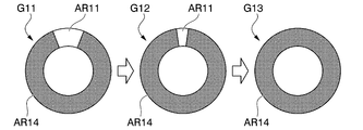
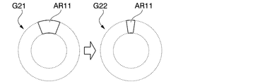
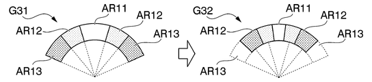
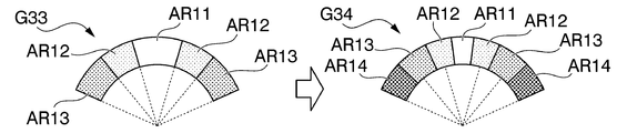
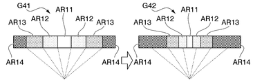
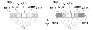
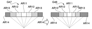
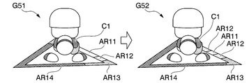
- the judgment area for each level of the operation evaluation is changed according to the passage of time within the operation time limit. Therefore, each region AR11 to AR14 in the guide image G is changed according to the passage of time. For example, by reducing the determination area for determining the operation evaluation as the first level with the passage of time, the direction instructed by the movement operation by the user and the first area AR11 (optimal direction) are set according to the passage of time. Becomes difficult to match. As a result, as time passes, it becomes more difficult to succeed in the movement operation for specifying the optimum direction.
- the determination area determined to be the second level and the determination area determined to be the third level may be reduced with the passage of time.
- the determination area determined to be the fourth level is relatively expanded as the other determination areas are reduced.
- the concept of reducing the determination area also includes the fact that the determination area disappears (disappears).
- the guide image G1 may include at least one determination region that is reduced with the passage of time.
- the following description is an example of a form in which the first region AR11, the second region AR12, and the third region AR13 in the guide image G are changed so as to be reduced with the passage of time.
- the fourth region AR14 changes so as to relatively expand as the other regions AR11 to AR13 shrink with the passage of time.
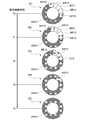
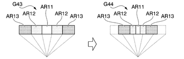
- FIG. 4 shows an example of a mode of change of each region AR11 to AR14 in the guide image G according to the passage of time within the operation time limit.
- the guide image G1 shows the states of the regions AR11 to AR14 at the time t0 when the operation time limit is started.
- the guide image G2 shows the states of the regions AR11 to AR14 at the timing when a certain time t1 elapses from the time t0 when the operation time limit is started.
- the guide image G3 shows the states of the regions AR11 to AR14 at the time t2 when a certain time has passed from the time t1.
- the guide image G4 shows the states of the regions AR11 to AR14 at the time t3 when a certain time has passed from the time t2.
- the guide image G5 shows the states of the regions AR11 to AR14 at the time t4 when the operation time limit ends.
- the state of the guide image G1 changes to the state of the guide image G2 according to the passage of time from the time t0 to the time t1. That is, the first region AR11, the second region AR12, and the third region AR13 change so as to gradually shrink around the optimum direction. On the other hand, the remaining fourth region AR14 changes so as to expand as the first region AR11, the second region AR12, and the third region AR13 shrink.
- the first region AR11 disappears and the second region AR12, the third region AR13, and the fourth region AR14 remain, as shown in the guide image G3. It becomes.
- the second region AR12 disappears further, and the third region AR13 and the fourth region AR14 remain, as shown in the guide image G4.
- the determination region that contributes to the operation evaluation includes at least the first region AR11, and depending on the embodiment, includes the second region AR12 and the third region AR13.
- the first region AR11 disappears at the timing before the end time of the operation time limit, but depending on the embodiment, the first region AR11 disappears at the timing when the end time of the operation time limit is reached. May or may not disappear. Further, even if the first region AR11 disappears at a timing before the end of the operation time limit, the timing of disappearance can be arbitrarily determined. Further, in this case, after the first region AR11 disappears, the remaining second region AR12 and third region AR13 are further reduced, and for example, at the timing when the end time of the operation time limit is reached, the second region AR12 disappears. , The third region AR13 and the fourth region AR14 may remain.
- the first region AR11, the second region AR12, the third region AR13, and the fourth region AR14 described above are included in the direction range in which the direction instructed by the movement operation by the user corresponds to the instruction direction to be operated by the user.
- This is a determination area (area for determining the operation direction) for determining whether or not the operation direction is satisfied.
- the regions AR11 to AR14 shown in FIGS. 3 and 4 are displayed.
- the circumference of the guide image G is divided into a plurality of regions AR11 to AR14, and the direction range is divided into a plurality of regions corresponding to the region divisions.
- each area AR11 to AR14 is displayed as a display mode indicating each of the direction ranges divided into a plurality of areas.
- each of the regions AR11 to AR14 will be referred to as a “direction region” because it is a region indicating a direction range.
- the central angles ⁇ 1, ⁇ 2, ⁇ 3, and ⁇ 4 are shown as the direction ranges corresponding to the respective regions AR11 to AR14 with respect to the center point O.
- the central angle ⁇ 1 is a central angle corresponding to the arc of the first region AR11 portion on the circumference of the guide image G.
- the central angle ⁇ 2 is a central angle corresponding to an arc when the second region AR12 arranged so as to sandwich the first region AR11 is regarded as a continuous region.
- the central angle ⁇ 3 is a central angle corresponding to an arc when the third region AR13 arranged so as to sandwich the first region AR11 and the second region AR12 is regarded as a continuous region.
- the central angle ⁇ 4 is a directional range that does not include any of the central angles ⁇ 1, ⁇ 2, and ⁇ 3 on the circumference of the guide image G, and is a central angle corresponding to the arc of the AR14 portion of the fourth region.
- the initial values of the central angles ⁇ 1, ⁇ 2, ⁇ 3, and ⁇ 4 of each area AR11 to AR14 are set.
- the initial value of the central angle ⁇ 1 is based on the basic ability and special ability of the character information of the fielder character C1 and the number of consecutive successful catches (an example of the result of the operation) as parameters for calculation. Calculated using. Specifically, it is set according to the magnification set based on the total value of the defensive power and the ball catching in the basic ability, the magnification set according to the special ability, and the number of consecutive successful catches. A value obtained by multiplying the magnification to be obtained by 360 ° is set as the initial value of the central angle ⁇ 1.
- the magnification set based on the defensive power and running power in the basic ability the magnification set according to the special ability, and the number of consecutive successful catches
- a value obtained by multiplying the magnification set by the above by 360 ° is set as the initial value of the central angle ⁇ 2.
- the magnification set based on the defensive power and the running power the magnification set according to the special ability, and the number of times in which the ball is successfully caught in succession are determined.
- a value obtained by multiplying the set magnification by 360 ° is set as the initial value of the central angle ⁇ 3.
- At least one of the initial values of the central angles ⁇ 1, ⁇ 2, and ⁇ 3 may be calculated using parameters different from those of the other initial values.
- the initial value of the central angle ⁇ 4 is obtained by subtracting the value of the central angle ⁇ 3 from 360 °.
- the magnification set according to the number of successful catches in succession decreases as the number of successful catches in succession increases. Is set. That is, as the fielder character C1, the higher the basic ability and the higher the special ability, the wider the first area AR11, the second area AR12, and the third area AR13 in the initial state are set, and the narrower the fourth area AR14 is set.
- the guide image G has the first region AR11, the second region AR12, and the third region AR13 (that is, the central angles ⁇ 1, ⁇ 2, depending on the passage of time within the operation time limit.
- the directional region (direction range) that contributes to the operation evaluation is gradually reduced so that the ⁇ 3) is reduced and the fourth region AR14 (that is, the central angle ⁇ 4) is expanded.
- the speed (region change speed) at which the directional region (direction range) that contributes to the operation evaluation gradually decreases with the passage of time is set according to a predetermined parameter (for example, ability parameter) set for the fielder character C1.
- the region change rate is the amount of change in the central angle for each region AR11 to AR14 per unit time.
- the area change speed is changed according to a predetermined basic ability of the fielder character C1 and the number of times that the ball is successfully caught in succession.
- the region change speed is set as follows.
- the area change speed of the fourth area AR14 is calculated based on the total value of the defensive power, the running power, and the shoulder power in the basic ability. This is used as the basic expansion speed, and the value obtained by multiplying the basic expansion speed by a magnification (coefficient) set according to the number of successful catches is calculated as the expansion speed of the fourth region AR14. ..
- the fourth region AR14 changes so as to expand the central angle ⁇ 4 according to the calculated expansion speed.
- the first region AR11, the second region AR12, and the third region AR13 change so as to uniformly reduce the central angles ⁇ 1, ⁇ 2, and ⁇ 3. May be made. That is, as the central angle ⁇ 4 expands by 3 °, the central angles ⁇ 1, ⁇ 2, and ⁇ 3 may each decrease by 3 °. That is, the region change speed, which is the amount of change in the central angle of each region AR11 to AR14 per unit time, is determined by the expansion speed of the fourth region AR14.
- the operation time limit will also change.
- the movement speed of the ball B hit by the knocker character C2 may change by changing the operation time limit in this way.
- FIG. 5 is a block diagram showing an example of the configuration of the game system 1 according to the present embodiment.
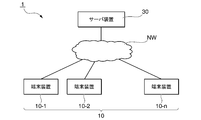
- the game system 1 is composed of a plurality of terminal devices 10-1, 10-2, ..., 10-n (n is a natural number) and a server device 30, and these devices are connected via a communication network NW. Be connected. Since the terminal devices 10-1, 10-2, ..., 10-n have the same configuration, they will be described simply as the terminal device 10 unless otherwise specified.
- the terminal device 10 functions as a game device by executing a game control program.
- the terminal device 10 is a computer device used by a user, and a game machine, a PC (Personal Computer), a tablet PC, a mobile phone such as a smartphone or a feature phone, and the like can be applied.
- a game machine e.g., a PC (Personal Computer), a tablet PC, a mobile phone such as a smartphone or a feature phone, and the like can be applied.
- the server device 30 manages game data and a game control program necessary for executing a game control program on the terminal device 10.
- the server device 30 is a computer device managed by a game operating company, and can be regarded as a system composed of a plurality of server machines, storage, network switches, routers, firewalls, and the like.
- the game data managed by the server device 30 is used when the game control program is executed on the terminal device 10, or is transmitted to the terminal device 10 in advance for use. Further, the game data may include advertising data (information on other games) displayed during the game. For example, the image displayed on the screen of the terminal device 10 is a part of the game data.
- the game control program managed by the server device 30 includes a part of the game control program.
- the game control program includes not only those downloaded to the terminal device 10 before the start of the game but also those downloaded to the terminal device 10 after the start of the game.
- the game control program downloaded to the terminal device 10 before the start of the game may be managed not by the server device 30 but by the server device that distributes the program that operates in the terminal device 10.
- FIG. 6 is a diagram showing an example of the hardware configuration of the terminal device 10 according to the present embodiment.
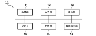
- the terminal device 10 includes, for example, a communication unit 11, an input unit 12, a display unit 13, a voice output unit 14, a storage unit 15, and a CPU (Central Processing Unit) 16.
- the terminal device 10 can use a general-purpose smartphone and does not require special hardware for executing the game control program, regardless of the processing power of the CPU. That is, if a program appropriately created according to the hardware configuration of the terminal device 10 on which the game control program is executed is used, a part of the hardware configuration may be different from the present embodiment.
- the communication unit 11 is a device that performs communication corresponding to the communication standard of the communication network NW such as wireless LAN, wired LAN, and mobile communication (LTE) capable of communicating between the terminal device 10 and the server device 30.
- NW such as wireless LAN, wired LAN, and mobile communication (LTE)
- the input unit 12 is a device capable of receiving interactive information during game execution.
- the interactive information is, for example, user operation information for the terminal device 10.
- Examples of the input unit 12 include physical devices such as buttons, keyboards, and levers that are mechanically operated, pointing devices (mouse and touch panel) that are GUI, and recognition devices (microphone, camera) that are voice and gesture.
- the input unit 12 may be integrally configured with the terminal device 10, or may be configured as a separate body connected by wire or wirelessly.
- the input unit 12 outputs an operation signal input based on the operation.
- the display unit 13 is a display that displays information such as images and texts, and includes, for example, a liquid crystal display panel, an organic EL (Electroluminescence) display panel, and the like.
- the display unit 13 may be configured as a separate body from the terminal device 10, and may be, for example, a television, an external monitor, or a head-mounted display (HMD).
- HMD head-mounted display
- the audio output unit 14 is configured to include, for example, an audio output terminal that outputs audio to a speaker, headphones, or the like.
- the storage unit 15 includes, for example, HDD (Hard Disk Drive), SSD (Solid State Drive), EEPROM (Electrically Complex Memory), ROM (Read-One Memory), ROM (Read-One Memory), ROM (Read-Ony Memory), ROM (Read-Ony Memory), ROM (Read-Ony Memory), ROM (Read-Ony Memory)
- the terminal device 10 stores various information, images, programs, and the like used for processing.
- the storage unit 15 is not limited to the one built in the terminal device 10, and may be an external storage device connected by a digital input / output port such as USB.
- the CPU 16 executes various programs stored in the storage unit 15 and controls each unit of the terminal device 10.
- the CPU 16 is an example of a processor that executes processing in the terminal device 10.
- the terminal device 10 may include a camera (not shown), a gyro sensor, a GPS (Global Positioning System) chip, an acceleration sensor, a magnetic sensor, an ambient light sensor, a proximity sensor, and a fingerprint sensor.
- FIG. 7 is a diagram showing an example of the functional configuration of the terminal device 10 according to the present embodiment.
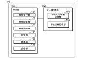
- a data storage unit 150 and a control unit 160 are shown as functional configurations of the terminal device 10.
- the data storage unit 150 has a functional configuration corresponding to the storage unit 15 shown in FIG. 7.
- the control unit 160 has a functional configuration realized by the CPU 16 executing the game control program stored in the storage unit 15.
- the data storage unit 150 includes a character information storage unit 151 and an area information storage unit 152 as a part for storing information necessary for executing a game process corresponding to the knock practice game of the present embodiment.
- the character information storage unit 151 stores information on a plurality of characters that can be used in the game.
- FIG. 8 shows an example of the character information D151 stored in the character information storage unit 151.
- the character information D151 is associated with a character ID, a character name, data indicating a character's ability, and the like.
- the character ID is identification information that identifies each character.
- the character name is the name of the character.
- the data indicating the character's ability includes basic ability data indicating "basic ability", special ability data indicating "special ability”, and the like. "Basic ability" is a basic ability possessed by a character.
- the basic ability data includes each ability parameter of "rank” and "ability value” corresponding to "defensive power", “running power”, “shoulder power”, “catch” and the like.
- “Defensive power” is a defensive ability. For example, the higher the defensive ability value, the faster the character can catch and throw.
- “Running power” is the running speed. For example, the higher the ability value of "running power”, the higher the running speed, the higher the probability of infield hits in an attack and the higher the success rate of stealing, the easier it is to advance, and the wider the defensive range in defense.
- “Shoulder strength” is the strength of the shoulder. For example, the higher the ability value of "shoulder strength", the higher the speed of the ball thrown by the character and the longer the distance.
- Catching is the ability to avoid errors. The higher the ability value of "catch”, the less likely it is to make an error.
- a "special ability” is an ability that a character can have other than a basic ability. As shown in the special ability data as "special ability # 1,""special ability # 2,"”special ability # 3,” etc., the ability to indicate whether or not the character has each predetermined special ability. Contains parameters. These ability parameters are parameters that affect the progress of the game. Note that these information are examples, and the character information D151 may be associated with information about various characters such as a character image of each character, a defensive position, and a form.
- the area information storage unit 152 stores the area setting information.
- the area setting information is information used in connection with the setting related to the guide image G.
- the setting related to the guide image G here includes the setting of the initial state of each area AR11 to AR14 in the guide image G and the setting of the area change speed in the operation time limit.
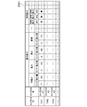
- FIG. 9 shows an example of the area setting information D152 stored in the area information storage unit 152.
- the area setting information D152 in the figure includes the first area setting information, the second area setting information, the third area setting information, and the fourth area setting information.
- the first region setting information is information used for setting the central angle ⁇ 1 of the first region AR11 in the initial state of the guide image G.
- the first area setting information includes continuous magnification information, basic magnification information, and special magnification information.
- the continuous magnification information is information indicating the magnification set according to the number of times in which the ball is continuously caught when setting the central angle ⁇ 1.
- the basic magnification information is information indicating a magnification set according to a predetermined basic ability (defensive force, catching ball) in the character information when setting the central angle ⁇ 1.
- the basic magnification information may indicate an arithmetic expression for calculating the magnification by using a predetermined basic ability as a variable.
- the special magnification information is information indicating the magnification set according to the special ability in the character information when setting the central angle ⁇ 1.
- the second region setting information is information used for setting the central angle ⁇ 2 of the second region AR12 in the initial state of the guide image G.
- the second area setting information includes continuous magnification information, basic magnification information, and special magnification information.
- the continuous magnification information is information indicating the magnification set according to the number of times in which the ball is continuously caught when setting the central angle ⁇ 2.
- the basic magnification information is information indicating a magnification set according to a predetermined basic ability (defensive force, running ability) in the character information when setting the central angle ⁇ 2.
- the basic magnification information may indicate an arithmetic expression for calculating the magnification by using a predetermined basic ability as a variable.
- the special magnification information is information indicating the magnification set according to the special ability in the character information when setting the central angle ⁇ 2.
- the third region setting information is information used for setting the central angle ⁇ 3 of the third region AR13 in the initial state of the guide image G.
- the third area setting information includes continuous magnification information, basic magnification information, and special magnification information.
- the continuous magnification information is information indicating the magnification set according to the number of times in which the ball is continuously caught when setting the central angle ⁇ 3.
- the basic magnification information is information indicating a magnification set according to a predetermined basic ability (defensive force, running ability) in the character information when setting the central angle ⁇ 3.
- the basic magnification information may indicate an arithmetic expression for calculating the magnification by using a predetermined basic ability as a variable.
- the special magnification information is information indicating the magnification set according to the special ability in the character information when setting the central angle ⁇ 3.
- the setting of the central angle ⁇ 4 of the fourth region AR14 in the initial state of the guide image G is relatively determined by setting the central angles ⁇ 1, ⁇ 2, and ⁇ 3.
- the fourth area setting information is information used for setting the expansion speed of the fourth area AR14.
- the fourth area setting information includes enlargement speed information and magnification setting information.
- the enlargement speed information is information for setting the basic enlargement speed.
- As the expansion speed information for example, an arithmetic expression for calculating the basic expansion speed may be shown with a predetermined basic ability (defensive power, running power, shoulder power) in the character information as a variable.
- the magnification setting information is information for setting a magnification to be multiplied by the calculated basic enlargement speed.
- the magnification setting information is, for example, information in which a value of a predetermined magnification is associated with the number of times in which the ball is successfully caught continuously.
- the control unit 160 includes an operation reception unit 161, an initial setting unit 162, a display control unit 163, a determination unit 164, and an evaluation unit 165 as functional units that realize game processing corresponding to the knock practice game of the present embodiment. And a change unit 166.
- the operation reception unit 161 receives an operation on the input unit 12.
- the operation reception unit 161 acquires the operation signal input to the input unit 12 based on the user's operation on the various game screens described above.
- the operation reception unit 161 accepts the movement operation.
- the initial setting unit 162 sets the direction region in the initial state of the guide image G.
- the initial setting unit 162 refers to the character information D151 (see FIG. 8) and the area setting information D152 (see FIG. 9) to set the ability parameters such as the basic ability and the special ability of the character information of the fielder character C1.
- the initial value of the direction region is determined.
- the initial setting unit 162 has the first region AR11, based on the number of successful catches in succession with the basic ability and special ability of the fielder character C1.
- the initial values of the central angles ⁇ 1, ⁇ 2, and ⁇ 3 of the second region AR12 and the third region AR13 are determined.
- the initial setting unit 162 determines the initial value of the central angle ⁇ 4 of the fourth region AR14 based on the determined initial values of the central angles ⁇ 1, ⁇ 2, and ⁇ 3.
- the display control unit 163 causes the display unit 13 to display an image corresponding to the above-mentioned home screen G100, game screen G200 (see FIGS. 1 and 2), and the like. For example, as shown in FIG. 2, the display control unit 163 causes the display unit 13 to display an image of the knock practice game including the guide image G as an image corresponding to the game screen G200. As described above, the guide image G is displayed as an object having a direction area as an indicator that instructs the instruction direction to be operated by the user.
- the display control unit 163 displays a guide image G including a direction region as an example of a display mode indicating a direction range corresponding to an instruction direction to be operated by the user.
- the display control unit 163 has a plurality of directional regions (first region AR11, second region AR12, third region AR13) indicating each of a plurality of directional ranges divided based on the central angles ⁇ 1, ⁇ 2, ⁇ 3, and ⁇ 4. , And the fourth area AR14) are displayed.
- the directional range corresponding to the first region AR11 is the directional range corresponding to the central angle ⁇ 1.
- the directional range corresponding to the second region AR12 is the directional range corresponding to the rest obtained by removing the central angle ⁇ 1 from the central angle ⁇ 2.
- the directional range corresponding to the third region AR13 is the directional range corresponding to the rest obtained by removing the central angle ⁇ 2 from the central angle ⁇ 3.
- the directional range corresponding to the fourth region AR14 is the directional range corresponding to the central angle ⁇ 4.
- the determination unit 164 determines whether the user's operation direction (operation direction of the movement operation) with respect to the instruction direction to be operated by the user is included in the predetermined direction range corresponding to the instruction direction.
- the predetermined directional range is a directional range corresponding to an instruction direction to be operated by the user, and is a directional range corresponding to at least one of the first region AR11, the second region AR12, and the third region AR13. ..
- the determination unit 164 determines which of the first region AR11, the second region AR12, the third region AR13, and the fourth region AR14 includes the direction instructed by the movement operation by the user. To determine the user's operating direction with respect to the instruction direction to be operated by the user. In addition, the determination unit 164 determines whether or not the movement operation has been performed within the operation time limit.
- the evaluation unit 165 evaluates the operation direction of the movement operation by the user based on the determination result of the determination unit 164. When it is determined that the user's operation direction is not included in the first area AR11, the evaluation unit 165 gives a lower evaluation than when it is determined that the user's operation direction is included in the first area AR11.
- the case where it is determined not to be included in the first region AR11 is the case where it is determined to be included in the second region AR12, the third region AR13, or the fourth region AR14. Further, when it is determined that the user's operation direction is not included in the first region AR11 and the second region AR12, the evaluation unit 165 is determined to be included in the first region AR11 and the second region AR12. Is also rated low.
- the case where it is determined that it is not included in either the first region AR11 or the second region AR12 is the case where it is determined that it is included in the third region AR13 or the fourth region AR14. Further, when the evaluation unit 165 determines that the user's operation direction is not included in the first region AR11, the second region AR12, and the third region AR13, the evaluation unit 165 determines that the first region AR11, the second region AR12, and the third region AR13 are not included. The evaluation is lower than when it is determined to be included in any of the three regions AR13. The case where it is determined that it is not included in the first region AR11, the second region AR12, and the third region AR13 is the case where it is determined that it is included in the fourth region AR14.
- the evaluation unit 165 gives the highest evaluation (first level). Further, when it is determined that the operation direction of the user is included in the second region AR12, the evaluation unit 165 gives the second highest evaluation (second level) among the five stages. Further, when it is determined that the operation direction of the user is included in the third region AR13, the evaluation unit 165 gives the third highest evaluation (third level) among the five stages. Further, when it is determined that the operation direction of the user is included in the fourth region AR14, the evaluation unit 165 gives the fourth highest evaluation (fourth level) among the five stages.
- the evaluation unit 165 gives the lowest evaluation (fifth level) among the five stages. For example, the evaluation unit 165 gives the user a high value point as the evaluation is high and a low value point as the evaluation is low, according to these evaluation results.
- the evaluation unit 165 may have a point of "zero" in the case of the lowest evaluation (fifth level). That is, the evaluation unit 165 does not have to give points in the case of the lowest evaluation (fifth level).
- the evaluation unit 165 gives the same evaluation in the case of the fourth highest evaluation (fourth level) and the lowest evaluation (fifth level) because both have failed to catch the ball, and has a low value. Points may be given to the user, or the points to be given may be "zero".
- points are an example of rewards given to users according to operation evaluation, and may be parameters other than points.
- the reward given to the user according to the operation evaluation may be a parameter such as a score or a coin instead of the point.
- the change unit 166 executes control regarding the change in the display mode in the guide image G.
- the change unit 166 gradually reduces the direction range within the operation time limit (reception period) in which the user's operation (movement operation) on the guide image G can be accepted.
- the changing unit 166 gradually reduces a part or all of the central angle ⁇ 1, the central angle ⁇ 2, and the central angle ⁇ 3 according to the passage of time within the operation time limit.
- the changing unit 166 gradually reduces the angle of any or all of the central angle ⁇ 1, the central angle ⁇ 2, and the central angle ⁇ 3 by the end of the operation time limit, and the changing unit 166
- the central angle ⁇ 4 is gradually increased corresponding to the gradual decrease of a part or all of the central angle ⁇ 1, the central angle ⁇ 2, and the central angle ⁇ 3.
- the change unit 166 has a central angle ⁇ 1 at a speed corresponding to the expansion speed based on the expansion speed information of the fourth region AR14 set in the fourth region setting information of the region setting information D152 (FIG. 9).
- the central angle ⁇ 2, and a part or all of the central angle ⁇ 3 are gradually decreased, and the central angle ⁇ 4 is gradually increased.
- the change unit 166 determines the value of the enlargement speed to be set in the enlargement speed information based on the ability parameters such as the basic ability and the special ability in the character information of the fielder character C1. It should be noted that this expansion speed (gradual increase speed of the central angle ⁇ 4) corresponds to the gradual decrease speed (region change speed) of the central angle ⁇ 1, the central angle ⁇ 2, and the central angle ⁇ 3.
- the display control unit 163 changes the display mode of each direction region according to the gradual decrease of the direction range by the change unit 166 according to the passage of time within the operation time limit (see FIG. 4). For example, the display control unit 163 makes at least one of the first region AR11, the second region AR12, and the third region AR13 corresponding to the gradual decrease of the central angle ⁇ 1, the central angle ⁇ 2, and the central angle ⁇ 3. Change so that the part shrinks. Further, the display control unit 163 changes the fourth region AR14 so as to expand in correspondence with the gradual decrease of the central angle ⁇ 4.
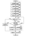
- the CPU 16 controls the game screen G200 so that the fielder character C1 is waiting for a knock (step S105). At this time, the fielder character C1 is set to exist at a predetermined defensive position on the ground, for example.
- the CPU 16 generates an image of the guidance image G in the initial state (step S121). At this time, the CPU 16 acquires information on a predetermined parameter or special ability in the basic ability of the fielder character C1 stored in the character information D151. In addition, the number of consecutive successful catches in this knock practice game so far is acquired.
- the CPU 16 has the initial values of the central angles ⁇ 1, ⁇ 2, and ⁇ 3 for determining the first region AR11, the second region AR12, and the third region AR13 in the initial state based on the acquired information and the area setting information D152. Is calculated.
- the CPU 16 calculates the central angle ⁇ 4 of the fourth region AR14 by using the initial values of the central angles ⁇ 1, ⁇ 2, and ⁇ 3.
- the CPU 16 generates an image of the guide image G based on the central angles ⁇ 1, ⁇ 2, ⁇ 3, and ⁇ 4 calculated as described above.
- the CPU 16 sets the area change speed (step S123).
- the region change rate is the amount of change in the central angle corresponding to each of the regions AR11 to AR14 per unit time, and is determined by the expansion speed of the fourth region AR14. That is, the CPU 16 calculates the expansion speed of the fourth region AR14 when setting the region change speed.
- the CPU 16 calculates the basic expansion speed based on the total value of predetermined basic abilities (defensive power, running power, shoulder power) stored in the character information of the fielder character C1 and the area setting information D152.
- the CPU 16 calculates the expansion speed by multiplying the calculated basic expansion speed by a magnification (indicated in the area setting information D152) according to the number of times the ball is successfully caught continuously.
- the order of processing may be changed. Alternatively, the processes of step S121 and step S123 may be executed in parallel.
- the CPU 16 starts an operation time limit for accepting a user's movement operation (step S125). At the start of counting the operation time limit, the CPU 16 calculates the operation time limit.
- the operation time limit may be calculated based on the initial value of the central angle ⁇ 4 of the fourth region AR14 calculated in step S121 and the expansion speed of the fourth region AR14 calculated in step S123. That is, the CPU 16 calculates the time from the initial state until the guide image G becomes only the fourth region AR14 based on the initial value of the central angle ⁇ 4 and the enlargement speed. The time calculated in this way is the operation time limit.
- the CPU 16 starts the movement display of the ball B (step S127).
- the CPU 16 determines the moving direction of the ball B (the direction of arrival of the ball B when viewed from the fielder character C1), and calculates the moving speed of the ball B.
- the moving direction of the ball B may be determined in advance according to the number of knocks, or may be determined at random, for example.
- the movement speed of the ball B is determined according to, for example, the operation time limit calculated in response to step S125 and the determined movement direction.
- the ball B passes from the position of the knocker character C2 to the defensive range of the fielder character C1. It can be calculated based on the distance to.
- the CPU 16 starts the movement display of the ball B so that the ball B is moved according to the movement direction determined as described above and the calculated movement speed.
- the CPU 16 starts displaying the guide image G (step S129).
- the CPU 16 displays the guidance image G in the initial state generated in step S121 so as to be arranged at a position corresponding to the fielder character C1.
- the CPU 16 arranges the guide image G in the initial state so that the first region AR11 indicates the moving direction of the ball B determined in step S106.
- the CPU 16 displays each area AR11 to AR14 in the guide image G so as to be reduced or enlarged according to the area change speed set in step S123.
- the order of processing may be changed in step S127 and step S129. Alternatively, the processes of step S127 and step S129 may be executed in parallel.
- the user recognizes that the timing at which the movement of the ball B is started in step S127 and the timing at which the display of the guide image G is started in step S129 are simultaneous.
- step S141 determines whether or not the movement operation has been performed.
- step S141: NO determines whether or not the operation time limit started in step S125 has expired (step S143). If it is determined that the operation time limit has not expired (step S143: NO), the process returns to step S141.
- step S125 it may be determined whether or not all of the direction regions of the guide image G have become the fourth region AR14 (red region). Good. That is, in the process of step S143, it may be determined that the direction regions of the guide image G are all the fourth region AR14 (red region) as the same timing as the end of the operation time limit. Further, it may be determined that a predetermined ratio or more of the direction regions of the guide image G is the fourth region AR14 (red region) as the same timing as the end of the operation time limit.
- step S147 the CPU 16 determines the direction area specified by the move operation (step S147). That is, the CPU 16 determines in which area of each area AR11 to AR14 the operation direction by the movement operation is included. At this time, in the arrangement state of each area AR11 to AR14 in the guide image G at the timing when the movement operation is performed, the CPU 16 includes the operation direction by the movement operation in any of the areas AR11 to AR14. Is determined. As a result, the direction region specified by the movement operation is determined.
- step S147 the CPU 16 determines in which direction region the operation direction of the movement operation is included, and evaluates the operation direction of the movement operation by the user based on the determination result. For example, as described above, when the CPU 16 determines that the operation direction is included in the first area AR11, it is evaluated at the first level, and when it is determined that the operation direction is included in the second area AR12, the first level is evaluated. There are two levels of evaluation. Further, when the CPU 16 determines that the operation direction is included in the third area AR13, it is evaluated as the third level, and when it is determined that the operation direction is included in the fourth area AR14, it is evaluated as the fourth level. To do.
- the CPU 16 displays a catching image according to the determination result in step S147 (that is, the operation direction by the movement operation) (step S151).
- the catching image is an image of the fielder character C1 catching the ball B on the game screen G200.
- the CPU 16 determines that the operation direction by the movement operation is included in the first region AR11
- the CPU 16 displays a catching image of catching the ball B in front (successful catching).
- the CPU 16 determines that the operation direction by the movement operation is included in the second region AR12
- the CPU 16 displays a catching image of the fielder character C1 jumping to the ball B and catching the ball (successful catching).
- the CPU 16 determines that the operation direction by the movement operation is included in the third region AR13, the CPU 16 displays a catching image of the fielder character C1 failing to catch the ball B and dropping it toward the front (ball catching failure). .. Further, when the CPU 16 determines that the operation direction by the movement operation is included in the fourth region AR14, the fielder character C1 cannot catch up with the ball B and cannot catch the ball (catch failure). Display the image.
- the CPU 16 gives points to the user according to the evaluation based on the determination result of the operation direction in step S147 (step S153). For example, the CPU 16 gives a higher point as the evaluation is higher, and gives a lower point as the evaluation is lower. The CPU 16 adds the value of the points given to the user to the accumulated points of the user so far, and updates the accumulated points.
- step S143 when it is determined in step S143 that the operation time limit has expired (step S143: YES), it means that the movement operation was desired to be performed within the operation time limit.
- the CPU 16 evaluates that the movement operation is a mistake (catch failure) (step S145). For example, the CPU 16 displays information indicating that the movement operation is a mistake (catch failure), and does not give points.
- the CPU 16 updates the display of the information presentation area AR10 arranged on the game screen G200 in response to the user's operation for the knock this time (step S171). Specifically, the CPU 16 changes the display contents of the points and the number of remaining balls in the information presentation area AR10 according to the knock this time. For example, the CPU 16 changes the display content to the value of the point updated in step S153. Further, the CPU 16 changes the display content so as to reduce the number of remaining balls by one.
- the CPU 16 increments the variable n (step S601).
- the CPU 16 determines whether or not the variable n incremented by step S601 is larger than the maximum value (step S603).
- the maximum value of the variable n corresponds to the number of knock exercises. When the variable n is equal to or less than the maximum value (step S603: NO), the number of knocked balls still remains. In this case, the process returns to step S103.
- step S603: YES the process of the figure is terminated. In this case, the knock practice game may be terminated.
- the terminal device 10 (an example of a game device) according to the present embodiment includes an operation reception unit 161 (an example of a reception unit), a display control unit 163, a determination unit 164, and a change unit 166.
- the operation reception unit 161 accepts the user's operation.
- the display control unit 163 displays a guide image G (an example of an object) having a direction region (for example, the first region AR11) which is an example of an indicator that indicates an instruction direction to be operated by the user.
- the determination unit 164 determines whether the user's operation direction (operation direction by the movement operation) with respect to the instruction direction is included in a predetermined direction range (for example, the central angle ⁇ 1) corresponding to the instruction direction.
- the changing unit 166 gradually reduces the direction range (for example, the central angle ⁇ 1) within the operation time limit, which is the reception period during which the user's operation in the indicated direction can be accepted.
- the display control unit 163 displays the directional region (for example, the first region AR11) in a display mode indicating the directional range, and corresponds to the gradual decrease of the directional range in the directional region (for example, the first region AR11). The display mode of is changed.
- the terminal device 10 gradually reduces the direction range corresponding to the instruction direction to be operated by the user during the reception period in which the user's operation can be accepted, and the direction corresponding to the gradually decrease in the direction range. Since the directional region indicating the range (for example, the first region AR11) is changed, it is possible to change the difficulty of the user's movement operation. As a result, the terminal device 10 can realize an effect of requesting the user to perform the movement operation at the earliest possible timing by gradually reducing the direction range of the operation direction to be operated by the movement operation.
- the above-mentioned direction range is gradually divided into a plurality of direction ranges (for example, a direction range based on a central angle ⁇ 1, a central angle ⁇ 2, and a central angle ⁇ 3) as the distance from the instruction direction to be operated by the user increases.
- the determination unit 164 determines whether or not the user's operation direction is included in any of the plurality of direction ranges.
- the change unit 166 has a direction range (for example, a central angle ⁇ 1 and a central angle ⁇ 2) divided into a plurality of directions according to the passage of time within the reception period (for example, the operation time limit) in which the user's operation (movement operation) can be received.
- the display control unit displays the first region AR11, the second region AR12, and the third region AR13 (an example of an indicator) as display modes indicating each of the direction ranges divided into a plurality of regions. At least a part of the first region AR11, the second region AR12, and the third region AR13 is changed in correspondence with the gradual decrease of the divided directional range.
- the terminal device 10 sets a plurality of directional ranges divided stepwise as the user moves away from the instruction direction to be operated within the reception period in which the user's operation (movement operation) can be accepted. It is gradually reduced with the passage of time, and at least a part of the first region AR11, the second region AR12, and the third region AR13 indicating each of the plurality of directional ranges is changed according to the passage of time. Therefore, it is possible to change the difficulty of the user's movement operation. As a result, the terminal device 10 can realize a game that requires the user to perform the movement operation at the earliest possible timing by gradually reducing the direction range of the operation direction to be operated by the movement operation with the passage of time. Is obtained.
- the terminal device 10 includes an evaluation unit 165 that evaluates the operation direction (operation direction by the movement operation) based on the determination result of the determination unit 164.
- the evaluation unit 165 determines that the operation direction is not included in the direction range (for example, the central angle ⁇ 1)
- the evaluation unit 165 gives a lower evaluation than when it is determined that the operation direction is included in the direction range.
- the evaluation unit 165 gives a lower evaluation than when it is determined that the operation direction is included in the first region AR11.
- the terminal device 10 is evaluated lower as the operation direction by the user's movement operation deviates from the instruction direction (optimal direction) to be operated by the user, so that the user corresponds to the optimum direction as much as possible. It is easier to get a high evaluation if the movement operation is performed while the range is wide. Therefore, the terminal device 10 has the effect of being able to realize a game that requires the user to perform the movement operation at the earliest possible timing.
- the change unit 166 gradually reduces the direction range so that the direction range (for example, the central angle ⁇ 1) becomes zero by the end of the reception period (for example, the operation time limit).
- the change unit 166 gradually reduces the first region AR11 so that the first region AR11 becomes zero by the end of the reception period (for example, the operation time limit).
- the terminal device 10 when the movement operation of the user exceeds the acceptance period (for example, the operation time limit), the terminal device 10 has no direction range corresponding to the instruction direction (optimal direction) to be operated by the user. Therefore, it is possible to realize a game that requires the user to perform the movement operation at the earliest possible timing.
- the acceptance period for example, the operation time limit
- the fielder character C1 (an example of a game object related to the user's operation) is set with an ability parameter (an example of the first parameter) that affects the progress of the game.
- the changing unit 166 determines the gradual deceleration rate when the directional range (for example, at least a part of the central angle ⁇ 1, the central angle ⁇ 2, and the central angle ⁇ 3) is gradually reduced according to the capability parameter.
- the change unit 166 determines the region change rate when at least a part of the first region AR11, the second region AR12, and the third region AR13 is gradually reduced according to the capacity parameter.
- the ability of the fielder character C1 affects the gradual decrease rate when the directional range (for example, the central angle ⁇ 1) is gradually decreased.
- the terminal device 10 can enhance the fun of the game because the difficulty level of the game changes depending on the training result of the fielder character C1.
- the terminal device 10 includes an initial setting unit 162.
- the initial setting unit 162 determines the initial value of the above-mentioned direction range (for example, at least a part of the central angle ⁇ 1, the central angle ⁇ 2, and the central angle ⁇ 3) based on the ability parameter of the fielder character C1.
- the ability of the fielder character C1 affects the initial value of the directional range (for example, the central angle ⁇ 1, the central angle ⁇ 2, and at least a part of the central angle ⁇ 3).
- the terminal device 10 can enhance the fun of the game because the difficulty level of the game changes depending on the training result of the fielder character C1.
- a unit game for example, one knock in a knock practice game
- a reception period for example, an operation time limit
- the initial setting unit 162 sets the above-mentioned direction range (for example, central angle ⁇ 1 and central angle ⁇ 2) in the “next unit game” or the “part or all unit game after the next”. , And at least a part of the central angle ⁇ 3).
- the terminal device 10 since the terminal device 10 changes the initial value of the direction range from the next time onward according to the user's operation result (for example, the ball catching result), the difficulty level of the game is changed according to the user's operation result. It becomes possible to enhance the fun of the game.
- a unit game for example, one knock in a knock practice game
- a reception period for example, an operation time limit
- the change unit 166 has the above-mentioned direction range (for example, central angle ⁇ 1, central angle ⁇ 2, etc.) in the “next unit game” or “part or all unit game after the next”. And at least a part of the central angle ⁇ 3) to determine the rate of tapering.
- the change unit 166 may use the first region AR11, the second region AR12, and the second region AR11 in the "next unit game” or the "part or all of the unit games after the next" based on the result in a certain unit game.
- the region change rate when at least a part of the three region AR13 is gradually reduced is determined.
- the terminal device 10 changes the gradual deceleration speed of the direction range from the next time onward according to the user's operation result (for example, the ball catching result), so that the difficulty level of the game is changed according to the user's operation result. It becomes possible to enhance the fun of the game.
- the user's operation result for example, the ball catching result
- a unit game for example, one knock in a knock practice game
- a reception period for example, an operation time limit
- an arbitrary direction is selected from a plurality of predetermined directions.
- the terminal device 10 randomly determines the direction to be operated by the user (the direction in which the ball B arrives) each time, the user needs to instantly determine the direction to be operated each time. .. Therefore, it is possible to enhance the fun of the game.
- the display control unit 163 is a contact on the game space.
- the guide image G (an example of an object) is displayed centering on the grounding position where the fielder character C1 is grounded on the ground (for example, the ground).
- the operation reception unit 161 can receive at least a user's operation (movement operation) with respect to the grounding position.
- the terminal device 10 indicates an instruction direction to be operated by the user, centering on the grounding position where the fielder character C1 to be operated by the user is grounded. For example, since the guide image G is displayed, the user can operate it intuitively, and the operability can be improved.
- the knock practice game may include a plurality of types of knock practice in which the operation content to be operated differs depending on the type of ball hit by the knocker, restrictions on catching, and the like.
- the knock practice of catching a ball hit by a knocker by moving the ball in the direction of arrival of the ball is referred to as a "normal ball” knock practice game.
- the knock practice game of the present embodiment in addition to the "normal ball", there are three types of "jump ball”, "thorn ball”, and "non-moving ball".
- the "jump ball” is a ball in which a ball hit by a knocker jumps and catches the ball, and the direction of the movement operation to be operated by the user is limited to the first region AR11.
- a “thorn ball” has a thorn on the ball hit by a knocker and needs to be avoided from the incoming ball. That is, the “thorn ball” is highly evaluated when the direction to be operated is opposite to that of the "normal ball” and the operation direction of the user is opposite to the instruction direction.
- the fielder character C1 In the "non-moving ball", the fielder character C1 must not move for a predetermined time until the ball hit by the knocker arrives.
- FIG. 11 shows an example of a basic flowchart of the knock practice game according to the present embodiment.
- the processing of steps S101, S103, S105, S601, and S603 in this figure is the same as the processing with the same reference numerals in FIG. 10, and the description thereof will be omitted.
- the CPU 16 selects the type of ball hit by the knocker (step S111). For example, the CPU 16 randomly selects from “normal ball”, “jump ball”, “thorn ball”, and “non-moving ball”. When the selected ball is neither a “jump ball”, a “thorn ball”, or a “non-moving ball” (steps S113, S115, S117: NO), the CPU 16 assumes that the "normal ball” is selected and is a normal ball.
- the process is executed (step S200).
- "jump ball” is selected (step S113: YES)
- the CPU 16 executes the jump ball process (step S300).
- step S115: YES the CPU 16 executes the thorn ball process (step S400).
- the CPU 16 executes the moving ball process (step S500).
- FIG. 12 is a flowchart showing a detailed example of the normal ball processing (step S200).
- the processes of steps S221, S223, S225, S227, and S229 in this figure correspond to the processes of steps S121, S123, S125, S127, and S129 in FIG. 10, and the description thereof will be omitted because they are the same processes.
- the guide image G displayed by the normal ball processing includes the first region AR11, the second region AR12, the third region AR13, and the fourth region AR14 (see FIG. 3).
- steps S241, S243, S245, and S247 of FIG. 12 corresponds to the processing of steps S141, S143, S145, and S147 of FIG.
- the CPU 16 determines which area of each area AR11 to AR14 includes the operation direction due to the movement operation (step S247). Further, the CPU 16 evaluates the operation direction of the movement operation by the user based on the determination result. For example, as described above, when the CPU 16 determines that the operation direction is included in the first area AR11 (white area), it evaluates it as the first level, and the operation direction is the second area AR12 (yellow area).
- the CPU 16 determines that the operation direction is included in the third area AR13 (green area), it evaluates it at the third level, and determines that the operation direction is included in the fourth area AR14 (red area). If so, it will be evaluated at the 4th level.
- the CPU 16 When it is determined that the operation direction by the movement operation is included in the first region AR11 (white region) (step S247: first region (white)), the CPU 16 corresponds to the first region AR11 (white region).
- the catching image is displayed (step S251). For example, the CPU 16 displays a state of catching the ball B in front (successful catching) as a catching image.
- the CPU 16 gives the user points corresponding to the first area AR11 (white area) (step S253). For example, the CPU 16 gives the highest points according to the first level and updates the accumulated points.
- step S247 second area (yellow)
- the CPU 16 corresponds to the second area AR12 (yellow area).
- the catching image is displayed (step S255). For example, the CPU 16 displays as a catching image how the fielder character C1 jumps at the ball B and catches it (successful catching). Further, the CPU 16 gives the user points according to the second area AR12 (yellow area) (step S257). For example, the CPU 16 assigns the second highest point according to the second level and updates the point cumulative value.
- the CPU 16 When it is determined that the operation direction by the move operation is included in the third area AR13 (green area) (step S247: third area (green)), the CPU 16 corresponds to the third area AR13 (green area).
- the catching image is displayed (step S259). For example, the CPU 16 displays as a catching image a state in which the fielder character C1 fails to catch the ball B and drops it toward the front (ball catching failure). Further, the CPU 16 gives the user points according to the third area AR13 (green area) (step S261). For example, the CPU 16 assigns the third highest point according to the third level and updates the point cumulative value. It should be noted that the CPU 16 does not have to give points because it has failed to catch the ball.
- the catching image corresponding to the fourth region AR14 (red region) in the operation direction by the movement operation is displayed (step S263).
- the CPU 16 displays the catching image corresponding to the fourth region AR14 (red region).
- the CPU 16 displays as a catching image a state in which the fielder character C1 cannot catch up with the ball B and cannot catch the ball (ball catching failure).
- the CPU 16 gives the user points according to the fourth area AR14 (red area) (step S265). For example, the CPU 16 assigns the fourth highest point according to the fourth level and updates the point cumulative value. It should be noted that the CPU 16 does not have to give points because it has failed to catch the ball.
- step S243 when it is determined in step S243 that the operation time limit has expired (step S243: YES), that is, when the movement operation is desired to be performed within the operation time limit, the CPU 16 makes a mistake in the movement operation (catch failure). ) (Step S245).
- the CPU 16 displays information (for example, "timing is late") indicating that the movement operation is a mistake (catch failure), and does not give points.
- step S225 it may be determined whether or not all of the direction regions of the guide image G have become the fourth region AR14 (red region). Good. That is, in the process of step S243, it may be determined that the entire direction region of the guide image G has become the fourth region AR14 (red region) as the same timing as the end of the operation time limit. Further, it may be determined that a predetermined ratio or more of the direction regions of the guide image G is the fourth region AR14 (red region) as the same timing as the end of the operation time limit.
- step S271 corresponds to the process of step S171 of FIG. 10, and the CPU 16 updates the display of the information presentation area AR10 arranged on the game screen G200 in response to the user's operation for the knock this time.
- FIG. 13 is a flowchart showing a detailed example of the jump ball process (step S300).
- the processing of steps S321, S323, S325, S327, and S329 in this figure corresponds to the processing of steps S121, S123, S125, S127, and S129 in FIG.
- the guide image G displayed by the jump ball processing includes only the first region AR11 and the fourth region AR14.
- the first region AR11 the second region AR12 and the third region AR13 of the first region AR11, the second region AR12, and the third region AR13 shown in FIG. 3 are also changed to white, and the first region AR11 , The second region AR12, and the third region AR13 may all be included.
- the CPU 16 displays a jump icon on the game screen G200 for the user to recognize that it is a "jump ball" (step S331).
- the jump icon is an icon displayed as "jump”.
- the order of the processes of step S327, step S329, and step S331 may be changed.
- the processes of step S327, step S329, and step S331 may be executed in parallel.
- the timing for displaying the jump icon is the timing when the movement of the ball B is started in step S327 and the timing when the display of the guide image G is started in step S329, at the same time from the user. It is the timing to be recognized.
- steps S341, S343, S345, and S347 of FIG. 13 correspond to the processes of steps S141, S143, S145, and S147 of FIG.
- the CPU 16 determines which region of the first region AR11 and the fourth region AR14 includes the operation direction due to the move operation (step S347). .. Further, the CPU 16 evaluates the operation direction of the movement operation by the user based on the determination result. For example, as described above, when the CPU 16 determines that the operation direction is included in the first region AR11 (white region), it is evaluated as the first level, and the operation direction is the fourth region AR14 (red region). If it is determined that it is included in, it will be evaluated at the 4th level.
- the CPU 16 When it is determined that the operation direction by the movement operation is included in the first region AR11 (white region) (step S347: first region (white)), the CPU 16 responds to the first region AR11 (white region).
- the catching image is displayed (step S351). For example, the CPU 16 displays a state of catching the ball B in front (successful catching) as a catching image. Further, the CPU 16 gives the user points corresponding to the first area AR11 (white area) (step S353). For example, the CPU 16 assigns points according to the first level and updates the accumulated points.
- the CPU 16 When it is determined that the operation direction by the movement operation is included in the fourth region AR14 (red region) (step S347: fourth region (red)), the CPU 16 responds to the fourth region AR14 (red region).
- the catching image is displayed (step S363). For example, the CPU 16 displays as a catching image a state in which the fielder character C1 cannot catch up with the ball B and cannot catch the ball (ball catching failure).
- the CPU 16 gives the user points according to the fourth area AR14 (red area) (step S365). For example, the CPU 16 assigns points according to the fourth level and updates the accumulated points. It should be noted that the CPU 16 does not have to give points because it has failed to catch the ball.
- step S343 when it is determined in step S343 that the operation time limit has expired (step S343: YES), that is, when the movement operation is desired to be performed within the operation time limit, the CPU 16 makes a mistake in the movement operation (catch failure). ) (Step S345).
- the CPU 16 displays information (for example, "timing is late") indicating that the movement operation is a mistake (catch failure), and does not give points.
- step S325 it may be determined whether or not all of the direction regions of the guide image G have become the fourth region AR14 (red region). Good. That is, in the process of step S343, it may be determined that the entire direction region of the guide image G has become the fourth region AR14 (red region) as the same timing as the end of the operation time limit. Further, it may be determined that a predetermined ratio or more of the direction regions of the guide image G is the fourth region AR14 (red region) as the same timing as the end of the operation time limit.
- step S371 corresponds to the process of step S171 of FIG. 10, and the CPU 16 updates the display of the information presentation area AR10 arranged on the game screen G200 in response to the user's operation for the knock this time.
- the guide image G including the first region AR11, the second region AR12, the third region AR13, and the fourth region AR14 is displayed, and the operation direction by the movement operation is determined and evaluated.
- the second region AR12 and the third region AR13 may also be determined and evaluated as the first region AR11 (white region).
- FIG. 14 is a flowchart showing a detailed example of the thorn ball processing (step S400).
- the processing of steps S421, S423, S425, S427, and S429 in this figure corresponds to the processing of steps S121, S123, S125, S127, and S129 in FIG.
- the guide image G displayed by the thorn ball processing includes the first region AR11, the second region AR12, the third region AR13, and the fourth region AR14, as in the normal ball processing.
- the CPU 16 displays a thorn ball icon on the game screen G200 for the user to recognize that it is a "thorn ball” (step S431).
- the thorn ball icon is an icon that displays an image of a "thorn ball” having thorns on the ball.
- the user can also recognize that the ball B coming from the knocker has a thorn.
- the order of the processes of step S427, step S429, and step S431 may be changed. Alternatively, the processes of step S427, step S429, and step S431 may be executed in parallel.
- the timing for displaying the thorn ball icon is the timing when the movement of the ball B (the ball with the thorn) is started in step S427 and the timing when the display of the guide image G is started in step S429. , It is the timing that the user recognizes that they are at the same time.
- steps S441, S443, S445, and S447 of FIG. 14 corresponds to the processing of steps S141, S143, S145, and S147 of FIG.
- the CPU 16 determines which area of each area AR11 to AR14 includes the operation direction due to the movement operation (step S447). Further, the CPU 16 evaluates the operation direction of the movement operation by the user based on the determination result. In the thorn ball processing, when the CPU 16 determines that the operation direction is included in any one of the first region AR11 (white region), the second region AR12 (yellow region), and the third region AR13 (green region). Is evaluated at the 4th level, and when it is determined that the operation direction is included in the 4th area AR14 (red area), the evaluation is performed at the 1st level.
- the CPU 16 displays an image corresponding to the 4th region AR14 (red region) (step S451). For example, the CPU 16 displays an image showing how the ball B (thorn ball) hits the fielder character C1 (escape failure). Further, the CPU 16 gives the user points according to the fourth area AR14 (red area) (step S453). For example, the CPU 16 assigns points according to the fourth level and updates the accumulated points. It should be noted that the CPU 16 does not have to give points because it is an escape failure. Alternatively, the CPU 16 may deduct from the accumulated points because it is an escape failure.
- the CPU 16 displays an image corresponding to the first area AR11 (white area) (step S447: fourth area (red)).
- Step S463 the CPU 16 displays an image showing how the fielder character C1 was able to avoid the ball B (thorn ball) (successful escape).
- the CPU 16 gives the user points corresponding to the first area AR11 (white area) (step S465). For example, the CPU 16 assigns points according to the first level and updates the accumulated points.
- step S443 when it is determined in step S443 that the operation time limit has expired (step S443: YES), that is, when the move operation is not performed within the operation time limit, the CPU 16 makes a mistake in the move operation (escape failure). Is evaluated (step S445). For example, the CPU 16 displays information indicating that the movement operation is a mistake (escape failure) (for example, "timing is late") and an image showing how the ball B (thorn ball) collides with the fielder character C1 to set a point. Do not grant.
- step S425 it may be determined whether or not all of the direction regions of the guide image G have become the fourth region AR14 (red region). Good. That is, in the process of step S443, it may be determined that the entire direction region of the guide image G has become the fourth region AR14 (red region) as the same timing as the end of the operation time limit. Further, it may be determined that a predetermined ratio or more of the direction regions of the guide image G is the fourth region AR14 (red region) as the same timing as the end of the operation time limit.
- step S471 corresponds to the process of step S171 of FIG. 10, and the CPU 16 updates the display of the information presentation area AR10 arranged on the game screen G200 in response to the user's operation for the knock this time.
- FIG. 15 is a flowchart showing a detailed example of the moving ball processing (step S500).
- the processing of steps S521, S523, S525, S527, and S529 in this figure corresponds to the processing of steps S121, S123, S125, S127, and S129 in FIG.
- the guide image G displayed by the non-moving ball process includes only the fourth region AR14.
- the fourth region AR14 may be the entire circumference of the guide image G in which the first region AR11, the second region AR12, and the third region AR13 shown in FIG. 3 are also changed to white-red.
- the CPU 16 displays a non-moving icon on the game screen G200 for the user to recognize that the ball is a “non-moving ball” (step S531).
- the do not move icon is an icon that is displayed as "do not move”.
- the order of the processes of step S527, step S529, and step S531 may be changed. Alternatively, the processes of step S527, step S529, and step S531 may be executed in parallel.
- the timing for displaying the non-moving icon is the timing when the movement of the ball B is started in step S527 and the timing when the display of the guide image G is started in step S529 at the same time from the user. It is the timing when it is recognized as being.
- step S541 of FIG. 15 corresponds to the process of step S141 of FIG.
- the CPU 16 evaluates that the movement operation is a mistake (catch failure) because the fielder character C1 has moved (step S541: YES). S545).
- the CPU 16 displays information (for example, "miss") indicating that the movement operation is a mistake (catch failure), and does not give points.
- step S541 determines whether or not a certain time has elapsed since the guide image G was displayed (step S549). .. If a certain time has not elapsed (step S549: NO), the process returns to step S541.
- step S549: YES the CPU 16 evaluates the first level based on the determination result, and displays a catching image corresponding to the first region AR11 (white region).
- Step S551 For example, the CPU 16 displays a state of catching the ball B in front (successful catching) as a catching image.
- the CPU 16 gives the user points corresponding to the first area AR11 (white area) (step S553). For example, the CPU 16 assigns points according to the first level and updates the accumulated points.
- the fixed time may be the operation time limit.
- step S571 corresponds to the process of step S171 of FIG. 10, and the CPU 16 updates the display of the information presentation area AR10 arranged on the game screen G200 in response to the user's operation for the knock this time.
- the CPU 16 displays the guide image G including the first region AR11, the second region AR12, the third region AR13, and the fourth region AR14, and displays the guide image G, as in the normal ball processing. If a certain period of time elapses without the movement operation being performed, it may be evaluated as the first level, and the catching image may be displayed and points may be given according to the first area AR11 (white area).
- a unit game for example, an operation time limit
- a reception period for example, an operation time limit
- an operation time limit capable of accepting a user's operation for an instruction in an instruction direction to be operated by the user for one time (operation time limit)
- operation time limit For example, one knock in a knock practice game
- a "normal ball” an example of a normal game
- thorn balls an example of the first special game
- the evaluation unit 165 is high when the user's operation direction is opposite to the above-mentioned instruction direction in the "thorn ball” in which the display of the thorn ball icon (an example of the first notification) that cannot occur in the "normal ball” occurs. It will be evaluated.
- the terminal device 10 includes not only a "normal ball” that should be operated according to the instruction direction, but also a “thorn ball” that is highly evaluated when the operation direction of the user is opposite to the instruction direction. Therefore, the game can be made highly diverse, and the fun of the game can be enhanced.
- a "normal ball” (an example of a normal game) that should be operated in the direction instructed by the user and a "moving ball” that should not be operated (second).
- An example of a special game and is included.
- the evaluation unit 165 has a reception period (for example, operation restriction) capable of accepting the user's operation in the "moving ball” in which the display of the moving icon (an example of the second notification) that cannot occur in the "normal ball” occurs. If the operation reception unit 161 does not accept the user's operation at the time), it is evaluated highly.
- the terminal device 10 is highly diverse because it includes not only a "normal ball” that should be operated in the instruction direction but also a “moving ball” that is highly evaluated not to be operated by the user. It can be made into a game, and it becomes possible to enhance the fun of the game.
- the magnification is changed according to the number of knocks instead of the number of consecutive successful catches. You may try to do so.
- the number of knocks is an example of the result of the operation, since the user is given the opportunity to perform one move operation each time a knock is made.
- the guide image G of the above embodiment may be configured to include only a part of each region AR11 to AR14.
- the configuration may include only the first region AR11, the second region AR12, and the fourth region AR14, or only the first region AR11 and the fourth region AR14.
- FIG. 16 is a diagram showing an example of a guide image G including only the first region AR11 and the fourth region AR14.
- the guide image G11 shows the states of the first region AR11 and the fourth region AR14 at the time of starting the display.
- the first region AR11 gradually shrinks around the optimum direction with the passage of time
- the fourth region AR14 gradually expands with the shrinkage, changing from the state of the guide image G11 to the state of the guide image G12. ..
- the first region AR11 may disappear and the guide image G13 may be changed to a state in which only the fourth region AR14 remains.
- the guide image G including only the first region AR11 and the fourth region AR14 corresponds to an example of the guide image G displayed in the jump ball processing.
- all of the first region AR11, the second region AR12, and the third region AR13 shown in FIG. 3 are designated as the first region AR11 (white region), and the first region AR11 and the fourth region AR14
- the guide image G including only is displayed.
- the number of directional regions (regions AR11 to AR14) included in the guide image G is not particularly limited. In this case, the number of directional regions included in the guide image G may be one. As an example, on the game screen G200, only one first region AR11 corresponding to the optimum direction may be arranged.
- FIG. 17 is a diagram showing an example of a guide image G that displays only the first region AR11.
- the guide image G21 shows the state of the first region AR11 at the start of display.
- the broken line portion is shown with reference to a portion other than the first region AR11 of the guide image G, but is not actually displayed.
- the first region AR11 gradually shrinks around the optimum direction, and changes from the state of the guide image G21 to the state of the guide image G22.
- the first region AR11 disappears and the guide image G itself is not displayed.
- the lowest predetermined point (an example of the parameter) may be assigned to the area where the first area AR11 is not arranged.
- the guide image G is arranged in a ring shape (doughnut shape) centered on the foot of the fielder character C1 (that is, so as to accommodate the fielder character C1).
- the guide image G may be arranged at a position that does not accommodate the fielder character C1, as long as the user can recognize the target direction.
- 18 and 19 show an example of a game screen of a knock practice game in which the positions of the guide images G are different.
- the guide image G is arranged at a position on the lower left side that does not overlap with the fielder character C1 (a position that is not the foot of the fielder character C1).
- the guide image G is arranged at a position on the lower left side that does not overlap with the fielder character C1 as in the example shown in FIG. 18, but it is not the elliptical shape shown in FIG.
- An example is shown in which the guide image G is displayed in a circular shape when viewed from above.
- the display position of the guide image G is not limited to the position of the fielder character C1, and flexible game expression becomes possible.
- the guide image G may be displayed around the game screen instead of around the fielder character C1.
- FIG. 20 shows an example in which the guide image G is displayed around the game screen.
- the regions AR11 to AR14 are arranged along the four sides around the screen (the innermost edge of the screen).
- the guide image G since the guide image G is arranged along the periphery of the screen, the guide image G has a quadrangular strip shape.
- At least one of the areas AR11 to AR14 may be displayed in the guide image G.
- the one directional region displayed is not limited to the first region AR11 corresponding to the optimum direction, and may be another directional region. As a result, it is possible to give the user a game property of playing by predicting another direction area from the displayed direction area and performing a movement operation.
- the guide image G is not limited to a circle, but may be an arc, a straight line, a polygon, or not a band.
- the first region AR11, the second region AR12, and the third region AR13 may be set as the guide image G, and the regions other than the guide image G may be set as the fourth region AR14.
- at least a part of the first region AR11, the second region AR12, and the third region AR13 may be changed with the passage of time as in the case of the circular shape.
- FIG. 21 shows an example of the arc-shaped guide image G.
- the shape of the guided image G31 shown is an arc strip containing only the first region AR11, the second region AR12, and the third region AR13.
- the first region AR11, the second region AR12, and the third region AR13 gradually decrease with the passage of time from the state of the guide image G31, and change to the state of the guide image G32.
- the fourth region AR14 may be displayed outside the first region AR11, the second region AR12, and the third region AR13 with the passage of time.
- FIG. 22 shows an example in which the fourth region AR14 is displayed with the passage of time on the arc-shaped guide image G.
- the shape of the guide image G33 shown is the same as the shape of the guide image G31 of FIG.
- the fourth region AR14 is gradually displayed in the gradually reduced portion along with the gradual decrease, and the guide image It changes to the state of G34.
- FIG. 23 shows an example of the linear guide image G.
- the shape of the guided image G41 shown is a strip in which the first region AR11, the second region AR12, the third region AR13, and the fourth region AR14 are arranged side by side in a straight line.
- the first region AR11, the second region AR12, and the third region AR13 gradually decrease with the passage of time from the state of the guide image G41, and the fourth region AR14 gradually increases with the gradual decrease and changes to the state of the guide image G42. ..
- the linear guide image G as in the example of the arc shape in FIG.
- the guide image G includes only the first region AR11, the second region AR12, and the third region AR13, and the fourth region AR14 is It may be an area other than the guide image G without being displayed.
- FIG. 24 shows an example of a linear guide image G in which the fourth region AR14 is not displayed.
- the shape of the guided image G43 shown is a straight strip containing only the first region AR11, the second region AR12, and the third region AR13. With the passage of time from the state of the guide image G43, the first region AR11, the second region AR12, and the third region AR13 gradually decrease, and the state changes to the state of the guide image G44.
- the fourth region AR14 may be displayed outside the first region AR11, the second region AR12, and the third region AR13 with the passage of time.
- FIG. 25 shows an example in which the fourth region AR14 is displayed with the passage of time on the linear guide image G.
- the shape of the guide image G45 shown is a straight strip containing only the first region AR11, the second region AR12, and the third region AR13, similar to the shape of the guide image G43 of FIG.
- the fourth region AR14 is gradually displayed in the gradually reduced portion along with the gradual decrease, and the guide image It changes to the state of G46.
- the illustrated guide image G47 has a strip shape in which the first region AR11, the second region AR12, the third region AR13, and the fourth region AR14 are arranged side by side in a straight line, similar to the shape of the guide image G41 in FIG.
- the second region AR12 and the third region AR13 gradually decrease with the passage of time from the state of the guide image G47, and the fourth region AR14 gradually increases with the gradual decrease, and changes to the state of the guide image G48. In this way, part of the directional region does not have to change over time.
- FIG. 27 shows an example of the polygonal guide image G.
- the illustrated guide image G51 is an example of a triangular guide image G.
- the first region AR11, the second region AR12, the third region AR13, and the fourth region AR14 are set in the strip-shaped regions on three sides.
- the first region AR11, the second region AR12, and the third region AR13 gradually decrease with the passage of time from the state of the guide image G51, and the fourth region AR14 gradually increases with the gradual decrease and changes to the state of the guide image G52. ..
- the guide image G is not limited to a triangle, but may be a quadrangle, a pentagon, a hexagon, or the like.
- the region change speed of the central angle ⁇ 4 in the guide image G may change with the passage of time.
- FIG. 28 shows an example of the change in the region change speed in the guide image G.
- the guide images G61 to G65 show an example of the change of the guide image G with the passage of time when the region change speed is constant.
- the first region AR11, the second region AR12, and the third region AR13 are constant according to the passage of time from the time t0 when the operation time limit starts to the time t4 when the operation time limit ends.
- the region changes at the rate of change in the region, and the fourth region AR14 gradually increases with the tapering.
- the guide images G71 to G75 show an example of the change of the guide image G with the passage of time when the region change speed gradually increases.
- the first region AR11, the second region AR12, and the third region AR13 gradually decrease, and the gradually decreasing speed gradually increases.
- the gradual decrease rate of the fourth region AR14 gradually increases.
- the central angle ⁇ 4 in the guide image G may reflect the change in the angle stepwise at regular time intervals based on the calculated enlargement speed.
- FIG. 29 shows an example in which the direction region in the guide image G changes stepwise.
- the first region AR11, the second region AR12, and the third region AR13 gradually decrease at a constant region change rate according to the passage of time from the time t0 to the time t4, and with the gradual decrease.
- the fourth region AR14 gradually increases.
- the guide images G91 to G95 were in the state of the guide image G91 at the time t0, but the state of the guide image G92 at the time t1, the state of the guide image G93 at the time t2, and the state of the guide image G94 at the time t3.
- the state of the guide image G95 is gradually changed. That is, in the guide images G91 to G95, the first region AR11, the second region AR12, and the third region AR13 gradually decrease at regular intervals, and the fourth region AR14 becomes constant at each time as the guide images gradually decrease. It gradually increases with time. As a result, the change in the directional region becomes gradual, and it is possible to give the user a game property that the movement operation is performed in an advantageous stage.
- FIG. 30 shows an example of the guide image G in which the first region AR11 does not change with the passage of time.
- the second region AR12 and the third region AR13 gradually decrease and the fourth region AR14 gradually increases in the order of the guide images G101 to G104 with the passage of time.
- the first region AR11 does not change.
- FIG. 31 shows an example of the guide image G in which the second region AR12 does not change with the passage of time.
- the first region AR11 and the third region AR13 gradually decrease and the fourth region AR14 gradually increases in the order of the guide images G111 to G114 with the passage of time.
- the second region AR12 does not change.
- the operation time limit may be set separately without depending on the change in the directional region.
- the operation time limit may be set to end before or after all the direction regions in the guide image G change to the fourth region AR14. As a result, it is possible to give the user a game property in which the movement operation is performed within the operation time limit other than the change in the direction area.
- the operation time limit depends on at least one of the basic ability and special ability of the fielder character or the number of times the ball is successfully caught in succession. It may change. As a result, it is possible to give the user a game property in which the movement operation is performed within the operation time limit different from the change in the direction area.
- Points (examples of parameters) corresponding to each area AR11 to AR14 are not assigned to the direction area of the guide image G, and the ball catching operation corresponding to the area in the direction specified by the movement operation is performed by the character. Points may be awarded according to the state of catching the ball.
- the ability parameter of the knocker character C2 is a parameter that affects the progress of the game, like the ability parameter of the fielder character C1.
- the ability parameter of the knocker character C2 is an ability parameter related to hitting.
- Ability parameters related to batting include "power" indicating the striking force when hitting the ball with the bat, "meet” indicating the accuracy when hitting the bat with the ball, and the like.
- the ability parameter of the knocker character C2 is set to the same value as the ability parameter set in the training part.
- the ability parameter of the knocker character C2 may be set uniformly in advance, or may be set in advance for each type of character. Further, the ability parameter of the knocker character C2 may be randomly determined for each game.
- the gradual decrease rate (region change speed) of the directional region (direction range) or the initial value of the directional region (direction range) may be determined according to the total value of the power and the meet of the knocker character C2.
- the ability parameters of the knocker character C2 are not limited to power and meet, and other ability parameters may be used.
- the knocker character C2 (an example of an opponent game object) that confronts the fielder character C1
- the knocker character C2 is set with an ability parameter (an example of a second parameter) that affects the progress of the game. ..
- the changing unit 166 determines the gradual reduction rate when the directional range (for example, at least a part of the central angle ⁇ 1, the central angle ⁇ 2, and the central angle ⁇ 3) is gradually reduced according to the ability parameter of the knocker character C2.
- the change unit 166 may determine the region change rate when at least a part of the first region AR11, the second region AR12, and the third region AR13 is gradually reduced according to the ability parameter of the knocker character C2. Good.
- the terminal device 10 affects the gradual decrease rate when the ability of the knocker character C2 gradually decreases the directional range (for example, at least a part of the central angle ⁇ 1, the central angle ⁇ 2, and the central angle ⁇ 3).
- the difficulty level of the game changes depending on the training result of the opponent game object (for example, the knocker character C2), so that the fun of the game can be enhanced.
- the fielder character C1 (an example of a game object related to the user's operation) is set with an ability parameter (an example of the first parameter) that affects the progress of the game.
- an ability parameter an example of the first parameter
- the knocker character C2 is set with an ability parameter (an example of a second parameter) that affects the progress of the game.
- the initialization unit 162 sets the direction range (for example, at least a part of the central angle ⁇ 1, the central angle ⁇ 2, and the central angle ⁇ 3) based on at least one of the ability parameter of the fielder character C1 and the ability parameter of the knocker character C2. Determine the initial value of.
- At least one of the ability of the fielder character C1 and one or both of the ability of the knocker character C2 is a directional range (for example, a central angle ⁇ 1, a central angle ⁇ 2, and a central angle ⁇ 3). Part) affects the initial value.
- the terminal device 10 can enhance the fun of the game because the difficulty level of the game changes depending on either or both of the training result of the fielder character C1 and the training result of the knocker character C2.
- the evaluation unit 165 may give a bonus evaluation according to the user's operation continuously performing a predetermined evaluation (for example, a first level evaluation).
- the bonus evaluation is an evaluation higher than the evaluation of the first level by a normal one operation.
- the evaluation unit 165 may give higher points (bonus points) as the bonus evaluation than in the evaluation of the first level.
- the changing unit 166 may increase the gradual deceleration speed (region change speed) of the directional region (direction range) with respect to the knocking of a part or all of the next time or after the next time.
- a plurality of unit games for example, one knock in a knock practice game
- a reception period for example, operation time limit
- the evaluation unit 165 gives a bonus evaluation according to a predetermined number of consecutive evaluations in a plurality of unit games.
- the changing unit 166 accelerates the gradual deceleration speed (region change speed) when the directional range (direction region) is gradually reduced in the "next unit game” or the "part or all unit game after the next".
- the terminal device 10 can obtain a higher evaluation and increase the difficulty of the game by continuously performing operations that can obtain a high evaluation, so that it is possible to enhance the interest of the game. become.
- the configuration of the present embodiment can be applied to a game other than the baseball game.
- a direction specifying element is combined with the timing operation as in the movement operation of the above embodiment.
- the configuration of the above embodiment can be applied to sports games other than baseball games such as soccer games, basketball games, and ice hockey games.
- the game to which the present invention is applied can also be used in esports.
- a program for realizing the function of the control unit 160 described above is recorded on a computer-readable recording medium, and the program recorded on the recording medium is read by the computer system and executed.
- the process as 160 may be performed.
- "loading a computer system a program recorded on a recording medium and executing it” includes installing the program in the computer system.
- the term "computer system” as used herein includes hardware such as an OS and peripheral devices. Further, the “computer system” may include a plurality of computer devices connected via a network including a communication line such as the Internet, WAN, LAN, and a dedicated line.
- the "computer-readable recording medium” refers to a portable medium such as a flexible disk, a magneto-optical disk, a ROM, or a CD-ROM, or a storage device such as a hard disk built in a computer system.
- the recording medium in which the program is stored may be a non-transient recording medium such as a CD-ROM.
- the recording medium also includes an internal or external recording medium that can be accessed from the distribution server to distribute the program.
- the code of the program stored in the recording medium of the distribution server may be different from the code of the program in a format that can be executed by the terminal device.
- the format stored in the distribution server does not matter as long as it can be downloaded from the distribution server and installed in a form that can be executed by the terminal device.
- the program may be divided into a plurality of parts, downloaded at different timings, and then combined by the terminal device, or the distribution server that distributes each of the divided programs may be different.
- a "computer-readable recording medium” is a volatile memory (RAM) inside a computer system that serves as a server or client when a program is transmitted via a network, and holds the program for a certain period of time. It shall include things.
- the above program may be for realizing a part of the above-mentioned functions.
- a so-called difference file (difference program) may be used, which can realize the above-mentioned functions in combination with a program already recorded in the computer system.
- a part or all of the functions of the above-mentioned control unit 160 may be realized as an integrated circuit such as an LSI (Large Scale Integration).
- LSI Large Scale Integration
- Each of the above-mentioned functions may be made into a processor individually, or a part or all of them may be integrated into a processor.
- the method of making an integrated circuit is not limited to LSI, and may be realized by a dedicated circuit or a general-purpose processor. Further, when an integrated circuit technology that replaces an LSI appears due to advances in semiconductor technology, an integrated circuit based on this technology may be used.
- One aspect of the present invention is a program executed by a computer included in a device that processes a game based on a user's operation, and includes a reception unit (161, S141) that accepts the user's operation. With a display control unit (163, S129, S229, S329, S429, S529) that displays an object (for example, a guide image G) having an indicator (for example, the first region AR11) that indicates an instruction direction to be operated by the user.
- a determination unit (164, S147, S247, S347, S447) for determining whether the user's operation direction with respect to the instruction direction is included in a predetermined direction range (for example, a central angle ⁇ 1) corresponding to the instruction direction.
- the changing unit (166, S123, S129, S223, S229,) that gradually reduces the direction range (for example, the central angle ⁇ 1) within the acceptance period (for example, the operation time limit) in which the user's operation in the indicated direction can be accepted.
- the computer is made to function as S323, S329, S423, S429, S523, S529), and the display control unit displays the indicator in a display mode (for example, first region AR11) indicating the direction range.
- This is a program that changes the display mode of the indicator in response to the gradual decrease of the direction range.
- the direction range corresponding to the instruction direction to be operated by the user is gradually reduced, and the display mode indicating the direction range corresponding to the gradually decreasing direction range. Therefore, it is possible to change the difficulty of the user's movement operation. As a result, by gradually reducing the direction range of the operation direction to be operated by the movement operation, it is possible to realize a game that requires the user to perform the movement operation at the earliest possible timing.
- Appendix A2 One aspect of the present invention is the program described in Appendix A1, wherein the direction range is gradually divided into a plurality of direction ranges as the distance from the indicated direction is increased, and the determination unit is described. It is determined whether or not the operation direction is included in any of the direction ranges divided into the plurality of directions, and the change unit determines the plurality of operation directions according to the passage of time within the reception period (for example, the operation time limit). Part or all of the directional range (for example, the directional range based on the central angle ⁇ 1, the central angle ⁇ 2, and the central angle ⁇ 3) is gradually reduced, and the display control unit divides the indicator into the plurality.
- the directional range for example, the directional range based on the central angle ⁇ 1, the central angle ⁇ 2, and the central angle ⁇ 3
- the indicator is displayed in a display mode (for example, 1st region AR11, 2nd region AR12, 3rd region AR13) indicating each of the directional ranges, and corresponds to the gradual decrease of the directional ranges divided into the plurality of directions. At least a part of the display mode indicating each of the plurality of directional ranges is changed.
- a display mode for example, 1st region AR11, 2nd region AR12, 3rd region AR13
- a plurality of directional ranges divided in stages as the user moves away from the instruction direction to be operated are gradually reduced with the passage of time.
- the display mode indicating each of the plurality of directional ranges changes with the passage of time, so that the difficulty of the user's movement operation can be changed.
- Appendix A3 One aspect of the present invention is the program described in Appendix A1 or Appendix A2, wherein the evaluation unit (165, S147, S247, S347) evaluates the operation direction based on the determination result of the determination unit. S447), the computer is further functioned, and when the evaluation unit determines that the operation direction is not included in the direction range (for example, central angle ⁇ 1, first region AR11), the evaluation unit includes the operation direction in the direction range. The evaluation is lower than when it is judged to be.
- the operation direction of the user's movement operation becomes lower as the distance from the instruction direction (optimal direction) to be operated by the user increases. Therefore, the movement operation is performed while the direction range corresponding to the optimum direction is as wide as possible. It is easier to get a high evaluation if you do. Therefore, it is possible to realize a game that requires the user to perform the movement operation at the earliest possible timing.
- Supplementary note A4 One aspect of the present invention is the program according to any one of Supplementary note A1 to Supplementary note A3, wherein the change unit is described by the end of the reception period (for example, operation time limit).
- the directional range is gradually reduced so that the directional range (for example, the central angle ⁇ 1 and the first region AR11) becomes zero.
- the timing is as early as possible. It is possible to realize a game that requires the user to perform a movement operation with.
- Appendix A5 One aspect of the present invention is the program described in any one of the appendices A1 to A4, and the game progresses for a game object (for example, a fielder character C1) related to a user operation.
- a first parameter for example, a capability parameter
- the changing portion gradually reduces the direction range (for example, central angle ⁇ 1, first region AR11) according to the first parameter. Determine the rate of tapering.
- the ability of the game object (for example, the fielder character C1) related to the user's operation affects the gradual decrease speed when the directional range (for example, the central angle ⁇ 1 and the first region AR11) is gradually reduced.
- the difficulty level of the game changes depending on the training result of the game object (for example, the fielder character C1), so that the fun of the game can be enhanced.
- Appendix A6 One aspect of the present invention is the program described in Appendix A5, in which an opponent game object (for example, knocker character C2) confronting the game object exists, and the opponent game object has a game progress.
- a second parameter (for example, a capability parameter) that affects the above is set, and the changing portion gradually reduces the direction range (for example, central angle ⁇ 1, first region AR11) according to the second parameter. Determine the gradual decrease rate (region change rate).
- the ability of the opponent game object affects the gradual decrease speed when the directional range (for example, the central angle ⁇ 1 and the first region AR11) is gradually reduced.
- the difficulty level of the game changes depending on the training result of the opponent game object (for example, the knocker character C2), so that the fun of the game can be enhanced.
- Appendix A7 One aspect of the present invention is the program described in any one of Appendix A1 to Appendix A4, and the game progresses for a game object (for example, fielder character C1) related to a user operation.
- a first parameter for example, an ability parameter
- a second parameter for example, an ability parameter
- the computer is further made to function as an initial setting unit for determining initial values of the direction range (for example, central angle ⁇ 1, central angle ⁇ 2, and central angle ⁇ 3).
- either or both of the ability of the game object (eg, fielder character C1) and the ability of the opponent game object (eg, knocker character C2) related to the user's operation are directional ranges (eg, for example). It affects the initial value of the central angle ⁇ 1 and the first region AR11).
- the difficulty level of the game changes depending on either or both of the training result of the game object (for example, the fielder character C1) and the training result of the opponent game object (for example, the knocker character C2). It will be possible to increase.
- One aspect of the present invention is the program according to any one of Supplementary notes A1 to A6, and the reception period (for example,) in which a user's operation for one instruction in the instruction direction can be accepted.
- Operation time limit is included in a unit game (for example, one knock in a knock practice game) is repeatedly performed multiple times, and based on the result in a certain unit game, the "next unit game” or "the next one” In the "unit or all unit game", the computer is further made to function as an initial setting unit for determining initial values of the direction range (for example, central angle ⁇ 1, central angle ⁇ 2, and central angle ⁇ 3).
- the initial value of the direction range from the next time onward changes according to the user's operation result (for example, the ball catching result)
- the user's operation result for example, the ball catching result
- Appendix A9 One aspect of the present invention is the program according to any one of Supplementary A1 to Appendix A8, and the reception period (for example,) in which a user's operation for one instruction in the instruction direction can be accepted.
- Operation time limit is included in a unit game (for example, one knock in a knock practice game) is repeatedly performed a plurality of times, and the changing part is based on the result in a certain unit game, or is the "next unit game” or.
- the gradual deceleration speed (region change speed) when the directional range is gradually reduced is determined.
- the gradual decrease speed of the direction range from the next time onward changes according to the user's operation result (for example, the ball catching result), so that the difficulty level of the game can be changed according to the user's operation result. , It becomes possible to enhance the fun of the game.
- One aspect of the present invention is the program according to any one of Supplementary notes A1 to A9, and the reception period (for example,) in which a user's operation for one instruction in the instruction direction can be accepted.
- Operation time limit is included in a unit game (for example, one knock in a knock practice game) is repeatedly performed a plurality of times, and the instruction direction instructed for each unit game is arbitrary from a plurality of predetermined directions. The direction is selected.
- the direction to be operated by the user (the direction in which the ball B arrives) is randomly determined each time, so that the user needs to instantly determine the direction to be operated each time. Therefore, it is possible to enhance the fun of the game.
- Appendix A11 One aspect of the present invention is the program described in Appendix A3, which is a unit including the reception period (for example, operation time limit) capable of accepting a user's operation for one instruction in the instruction direction.
- a game for example, one knock in a knock practice game
- the evaluation unit evaluates a bonus according to a predetermined number of consecutive evaluations in the plurality of unit games. Is given, and the changing unit accelerates the gradual deceleration speed (region change speed) when the directional range is gradually reduced in the "next unit game" or the "part or all unit game after the next".
- Appendix A12 One aspect of the present invention is the program described in Appendix A3, which is a unit including the reception period (for example, operation time limit) capable of accepting a user's operation for one instruction in the instruction direction.
- a game for example, one knock in a knock practice game
- a normal game for example, a “normal ball”
- a first special game for example, "thorn ball”
- the evaluation unit displays a first notification (for example, a thorn ball icon) that cannot occur in the normal game. ) Occurs, the first special game is evaluated highly when the user's operation direction is opposite to the instruction direction.
- Appendix A13 One aspect of the present invention is the program described in Appendix A3, which includes the reception period (for example, operation time limit) capable of accepting a user's operation for one instruction in the instruction direction.
- a game for example, one knock in a knock practice game
- each of the plurality of unit games includes a normal game (for example, a “normal ball”) that should be operated in the indicated direction.
- a second special game eg, a "moving ball” that should not be manipulated is included, and the evaluation unit receives a second notification (eg, displaying a non-moving icon) that cannot occur in the normal game.
- a high evaluation is given when the reception unit does not accept the user's operation during the reception period.
- Appendix A14 One aspect of the present invention is the program described in any one of Appendix A1 to Appendix A13, in which a game object (for example, a fielder character C1) is set in a game space (for example, for example) based on a user operation.
- a game object for example, a fielder character C1
- the display control unit In a game to be moved in a baseball field, the display control unit is centered on a grounding position where the game object is grounded on a grounding surface (for example, the ground) on the game space. Is displayed, and the reception unit can accept at least the user's operation on the ground contact position.
- the object for example, the guide image G
- the game object for example, the fielder character C1 to be operated by the user is in contact with the ground. Since it is displayed, the user can operate it intuitively, and it is possible to improve the operability.
- One aspect of the present invention is a game processing method executed by a computer included in a device that processes a game based on a user's operation, and includes a step (S141) of accepting the user's operation and a user. Steps (S129, S229, S329, S429, S529) for displaying an object (for example, a guide image G) having an indicator (for example, the first region AR11) instructing the instruction direction to be operated, and the instruction direction.
- an object for example, a guide image G
- an indicator for example, the first region AR11
- the indicator is displayed in a display mode (for example, the first region AR11) indicating the direction range, and the indicator corresponds to the gradual decrease of the direction range.
- This is a game processing method that changes the display mode.
- the direction range corresponding to the instruction direction to be operated by the user is gradually reduced, and the display mode indicating the direction range corresponding to the gradually decreasing direction range. Therefore, it is possible to change the difficulty of the user's movement operation. As a result, by gradually reducing the direction range of the operation direction to be operated by the movement operation, it is possible to realize a game that requires the user to perform the movement operation at the earliest possible timing.
- One aspect of the present invention is a game device that processes a game based on a user's operation, and instructs a reception unit (161) that accepts the user's operation and an instruction direction to be operated by the user.
- the display control unit (163) for displaying an object (for example, the guide image G) having an indicator (for example, the first region AR11) and the user's operation direction with respect to the instruction direction are predetermined directions corresponding to the instruction direction.
- the direction range (for example, the operation time limit) is included in the determination unit (164) for determining whether the user is included in the range (for example, the central angle ⁇ 1) and the reception period (for example, the operation time limit) in which the user's operation with respect to the instruction direction can be accepted.
- the display control unit includes a change unit (166) that gradually reduces the central angle ⁇ 1), and the display control unit displays the indicator in a display mode (for example, the first region AR11) indicating the direction range. It is a game device that changes the display mode of the indicator in accordance with the gradual decrease of the direction range.
- the direction range corresponding to the instruction direction to be operated by the user is gradually reduced, and the display mode indicating the direction range corresponding to the gradually decreasing direction range. Therefore, it is possible to change the difficulty of the user's movement operation. As a result, by gradually reducing the direction range of the operation direction to be operated by the movement operation, it is possible to realize a game that requires the user to perform the movement operation at the earliest possible timing.
- One aspect of the present invention is a step (S141) of accepting an operation of designating a direction and a step of arranging a target area (areas AR11 to AR14) designated by the operation on the screen. (S129) and a program for executing the step (S123, S129) of changing the region with the passage of time during the time during which the operation is possible.
- the difficulty of the movement operation can be changed according to the passage of time by changing the area according to the passage of time.
- the target area designated by the movement operation with the passage of time it is possible to realize a game that requires the user to perform the movement operation at the earliest possible timing.
- Appendix B2 One aspect of the present invention is the program described in Appendix B1, in which the step to be changed is based on the result of the movement operation (for example, the number of consecutive successful catches).
- the speed at which the region is changed is changed according to the above (step S123).
- the speed at which the area is changed is changed according to the result of the movement operation.
- the user can change the difficulty level of the game according to the result of the movement operation, and the fun of the game can be enhanced.
- Appendix B3 One aspect of the present invention is the program described in Appendix B1 or Appendix B2, wherein the changing step is set to a predetermined character (fielder character C1) associated with the movement operation. Based on the parameters (for example, special abilities such as defensive power, running power, shoulder power, etc. in the basic information), the speed at which the area is changed with the passage of time is changed (step S123).
- a predetermined character for example, special abilities such as defensive power, running power, shoulder power, etc. in the basic information
- the speed at which the area is changed is changed according to the parameters of the character.
- Appendix B4 One aspect of the present invention is the program described in any one of the appendices B1 to B3, in which a step of assigning parameters (for example, points) to each of the regions to a computer and the operation thereof. Further execution of steps (S153, S171) of changing the user's parameters (eg, point cumulative value) based on the parameters assigned to the area according to the designated direction.
- parameters for example, points
- steps (S153, S171) of changing the user's parameters eg, point cumulative value
- the user's parameters are changed based on the parameters assigned to the area specified by the user's operation.
- the user is made to perform the operation of designating the area with the goal of changing the parameters as advantageous as possible, and the interest of the game can be enhanced.
- Appendix B5 One aspect of the present invention is the program according to any one of Appendix B1 to B4, wherein the changing step is at least one region (first region AR11, second region AR12, third region).
- the area AR13) is reduced with the passage of time, and the area other than the area to be reduced (the fourth area AR14) is expanded with the passage of time (S129).
- the area that produces a result that is advantageous to the user when specified by an operation is reduced with the passage of time, while the area that produces a result that is disadvantageous to the user when specified by an operation is reduced over time. It can be expanded over time. In this case, since the possibility that the user becomes disadvantageous increases with the passage of time, it is possible to further strongly urge the user to perform the movement operation at an early timing.
- Appendix B6 One aspect of the present invention is the program according to any one of Appendix B1 to B5, in which the changing step changes the initial state of the region based on the result of the operation. (S121).
- the initial state of the area is changed according to the result of the move operation.
- the initial state of the area it is possible to change the difficulty level of the game, and it is possible to enhance the fun of the game.
- One aspect of the present invention can include a step (S141) for accepting an operation for designating a direction, a step (S129) for arranging a target area designated by the operation on the screen, and the operation. It is a game processing method including a step (S123, S129) of changing the area according to the passage of time during a certain period of time.
- One aspect of the present invention includes an operation reception unit (161) for receiving an operation for designating a direction, an arrangement unit (163) for arranging a target area designated by the operation on the screen, and the above. It is a game device including a changing unit (166) that changes the area according to the passage of time during an operationable time.
- 1 game system 10 (10-1, 10-2) terminal device, 11 communication unit, 12 input unit, 13 display unit, 14 audio output unit, 15 storage unit, 16 CPU, 30 server device, 150 data storage unit, 151 character information storage unit, 152 area information storage unit, 160 control unit, 161 operation reception unit, 162 initial setting unit, 163 display control unit, 164 judgment unit, 165 evaluation unit, 166 change unit
Landscapes
- Engineering & Computer Science (AREA)
- Multimedia (AREA)
- Human Computer Interaction (AREA)
- Theoretical Computer Science (AREA)
- General Engineering & Computer Science (AREA)
- Physics & Mathematics (AREA)
- General Business, Economics & Management (AREA)
- Computer Security & Cryptography (AREA)
- Optics & Photonics (AREA)
- Business, Economics & Management (AREA)
- General Physics & Mathematics (AREA)
- Processing Or Creating Images (AREA)
- User Interface Of Digital Computer (AREA)
Applications Claiming Priority (4)
| Application Number | Priority Date | Filing Date | Title |
|---|---|---|---|
| JP2019-150735 | 2019-08-20 | ||
| JP2019150735 | 2019-08-20 | ||
| JP2020-044556 | 2020-03-13 | ||
| JP2020044556A JP7138951B2 (ja) | 2019-08-20 | 2020-03-13 | プログラム、ゲーム処理方法、及びゲーム装置 |
Publications (1)
| Publication Number | Publication Date |
|---|---|
| WO2021033606A1 true WO2021033606A1 (ja) | 2021-02-25 |
Family
ID=74661057
Family Applications (1)
| Application Number | Title | Priority Date | Filing Date |
|---|---|---|---|
| PCT/JP2020/030690 Ceased WO2021033606A1 (ja) | 2019-08-20 | 2020-08-12 | プログラム、ゲーム処理方法、及びゲーム装置 |
Country Status (3)
| Country | Link |
|---|---|
| JP (4) | JP7138951B2 (cg-RX-API-DMAC7.html) |
| TW (1) | TWI752590B (cg-RX-API-DMAC7.html) |
| WO (1) | WO2021033606A1 (cg-RX-API-DMAC7.html) |
Families Citing this family (1)
| Publication number | Priority date | Publication date | Assignee | Title |
|---|---|---|---|---|
| EP4741029A1 (en) * | 2024-11-07 | 2026-05-13 | Mi Hiepa Scout Limited | Graphical overlay method |
Citations (4)
| Publication number | Priority date | Publication date | Assignee | Title |
|---|---|---|---|---|
| JP2015223393A (ja) * | 2014-05-29 | 2015-12-14 | フリュー株式会社 | ビデオゲーム装置、ビデオゲーム装置の制御方法、ビデオゲーム制御プログラムおよび記録媒体 |
| JP2016146900A (ja) * | 2015-02-10 | 2016-08-18 | 株式会社バンダイナムコエンターテインメント | プログラムおよびゲーム装置 |
| JP2018023449A (ja) * | 2016-08-08 | 2018-02-15 | 任天堂株式会社 | 情報処理装置、ゲームプログラムおよびゲーム制御方法 |
| JP2018171250A (ja) * | 2017-03-31 | 2018-11-08 | 株式会社バンダイナムコエンターテインメント | プログラム、サーバ及びゲームシステム |
Family Cites Families (4)
| Publication number | Priority date | Publication date | Assignee | Title |
|---|---|---|---|---|
| JP4729113B2 (ja) | 2009-03-12 | 2011-07-20 | 株式会社コナミデジタルエンタテインメント | ゲーム装置、ゲーム制御方法、及び、プログラム |
| KR101197894B1 (ko) * | 2010-12-31 | 2012-11-05 | (주)네오위즈게임즈 | 야구게임에서 홈런레이스를 제공하는 방법 및 게임 서버 |
| JP2018015547A (ja) * | 2017-05-16 | 2018-02-01 | 株式会社コロプラ | 表示制御方法および当該表示制御方法をコンピュータに実行させるためのプログラム |
| JP6696077B2 (ja) | 2018-03-15 | 2020-05-20 | 株式会社コナミデジタルエンタテインメント | ゲームシステム、ゲーム制御装置、及びプログラム |
-
2020
- 2020-03-13 JP JP2020044556A patent/JP7138951B2/ja active Active
- 2020-08-12 WO PCT/JP2020/030690 patent/WO2021033606A1/ja not_active Ceased
- 2020-08-17 TW TW109127883A patent/TWI752590B/zh active
-
2022
- 2022-08-26 JP JP2022134824A patent/JP7501929B2/ja active Active
-
2024
- 2024-05-28 JP JP2024086666A patent/JP7745914B2/ja active Active
-
2025
- 2025-09-04 JP JP2025146866A patent/JP2025179176A/ja active Pending
Patent Citations (4)
| Publication number | Priority date | Publication date | Assignee | Title |
|---|---|---|---|---|
| JP2015223393A (ja) * | 2014-05-29 | 2015-12-14 | フリュー株式会社 | ビデオゲーム装置、ビデオゲーム装置の制御方法、ビデオゲーム制御プログラムおよび記録媒体 |
| JP2016146900A (ja) * | 2015-02-10 | 2016-08-18 | 株式会社バンダイナムコエンターテインメント | プログラムおよびゲーム装置 |
| JP2018023449A (ja) * | 2016-08-08 | 2018-02-15 | 任天堂株式会社 | 情報処理装置、ゲームプログラムおよびゲーム制御方法 |
| JP2018171250A (ja) * | 2017-03-31 | 2018-11-08 | 株式会社バンダイナムコエンターテインメント | プログラム、サーバ及びゲームシステム |
Non-Patent Citations (1)
| Title |
|---|
| ANONYMOUS: "Speed knock", KONAMIDIGITAL ENTERTAINMENT CO. LTD, 4 October 2019 (2019-10-04), pages 1 - 2, Retrieved from the Internet <URL:https://asc.s.konaminet.jp/asc/pawasma/webpage/news/event_championroad/2019_baseball/rule_SpeedKnock_lutvreqP.php?set_user_id=0> [retrieved on 20201023] * |
Also Published As
| Publication number | Publication date |
|---|---|
| JP7138951B2 (ja) | 2022-09-20 |
| JP2024103591A (ja) | 2024-08-01 |
| JP7501929B2 (ja) | 2024-06-18 |
| JP2022173204A (ja) | 2022-11-18 |
| JP7745914B2 (ja) | 2025-09-30 |
| JP2021035486A (ja) | 2021-03-04 |
| JP2025179176A (ja) | 2025-12-09 |
| TW202112422A (zh) | 2021-04-01 |
| TWI752590B (zh) | 2022-01-11 |
Similar Documents
| Publication | Publication Date | Title |
|---|---|---|
| JP7515201B2 (ja) | ゲームシステム、ゲーム制御装置、プログラム、及びゲーム制御方法 | |
| JP2023024720A (ja) | ゲームシステム、ゲーム制御装置、及びプログラム | |
| JP7485397B2 (ja) | ゲームシステム、ゲーム制御装置、プログラム、及びゲーム制御方法 | |
| JP6748810B2 (ja) | ゲームシステム、ゲーム制御装置、及びプログラム | |
| KR20160132371A (ko) | 게임 관리 장치, 게임 시스템, 프로그램 및 기록 매체 | |
| JP2025179176A (ja) | プログラム、ゲーム処理方法、及びゲーム装置 | |
| JP7804981B2 (ja) | ゲームシステム、ゲーム制御装置及びプログラム | |
| TWI772624B (zh) | 遊戲系統、遊戲控制裝置、電腦程式產品及遊戲控制方法 | |
| JP7300827B2 (ja) | ゲームプログラム、方法、および情報処理装置 | |
| JP5229836B2 (ja) | ゲームシステム、ゲームシステムの制御方法、及びプログラム | |
| JP7661422B2 (ja) | ゲーム装置、ゲームプログラム | |
| JP7025808B1 (ja) | コンピュータプログラム、それに用いるゲームシステム、及び制御方法 | |
| JP6277474B2 (ja) | ゲーム制御装置、ゲームシステム、及びプログラム | |
| JP3894485B2 (ja) | ゲームにおけるボールの着地点決定プログラム | |
| JP7115764B2 (ja) | ゲームシステム、ゲーム制御装置、及びプログラム | |
| JP6647665B2 (ja) | ゲーム制御装置、ゲームシステム及びプログラム | |
| JP6479942B1 (ja) | ゲームプログラム、方法、および情報処理装置 | |
| JP2022139469A (ja) | ゲームプログラム、ゲーム処理方法、及びゲーム装置 | |
| JP2024060722A (ja) | ゲームシステム、ゲーム制御装置及びプログラム | |
| JP2024027966A (ja) | ゲーム制御装置、ゲームシステム及びプログラム | |
| JP5350425B2 (ja) | ゲームシステム、ゲームシステムの制御方法、及びプログラム |
Legal Events
| Date | Code | Title | Description |
|---|---|---|---|
| 121 | Ep: the epo has been informed by wipo that ep was designated in this application |
Ref document number: 20854217 Country of ref document: EP Kind code of ref document: A1 |
|
| NENP | Non-entry into the national phase |
Ref country code: DE |
|
| 122 | Ep: pct application non-entry in european phase |
Ref document number: 20854217 Country of ref document: EP Kind code of ref document: A1 |