WO2021029762A1 - Paroi intelligente - Google Patents
Paroi intelligente Download PDFInfo
- Publication number
- WO2021029762A1 WO2021029762A1 PCT/KR2020/095117 KR2020095117W WO2021029762A1 WO 2021029762 A1 WO2021029762 A1 WO 2021029762A1 KR 2020095117 W KR2020095117 W KR 2020095117W WO 2021029762 A1 WO2021029762 A1 WO 2021029762A1
- Authority
- WO
- WIPO (PCT)
- Prior art keywords
- screen
- smart wall
- driving roller
- coupled
- wall
- Prior art date
Links
- 238000000034 method Methods 0.000 claims description 36
- 239000002184 metal Substances 0.000 claims description 33
- 229910052751 metal Inorganic materials 0.000 claims description 33
- 239000004744 fabric Substances 0.000 claims description 23
- 239000000463 material Substances 0.000 claims description 10
- 239000007779 soft material Substances 0.000 claims description 5
- 229920001296 polysiloxane Polymers 0.000 claims description 2
- 229910000831 Steel Inorganic materials 0.000 description 30
- 239000010959 steel Substances 0.000 description 30
- 238000010586 diagram Methods 0.000 description 16
- 239000000047 product Substances 0.000 description 16
- 208000027418 Wounds and injury Diseases 0.000 description 11
- 238000009434 installation Methods 0.000 description 8
- 238000005452 bending Methods 0.000 description 6
- 230000008859 change Effects 0.000 description 5
- XLYOFNOQVPJJNP-UHFFFAOYSA-N water Substances O XLYOFNOQVPJJNP-UHFFFAOYSA-N 0.000 description 5
- 230000001932 seasonal effect Effects 0.000 description 4
- 229910052710 silicon Inorganic materials 0.000 description 4
- 239000010703 silicon Substances 0.000 description 4
- 230000037303 wrinkles Effects 0.000 description 4
- 230000008901 benefit Effects 0.000 description 3
- 230000008878 coupling Effects 0.000 description 3
- 238000010168 coupling process Methods 0.000 description 3
- 238000005859 coupling reaction Methods 0.000 description 3
- 230000000694 effects Effects 0.000 description 3
- 238000005192 partition Methods 0.000 description 3
- 238000004804 winding Methods 0.000 description 3
- 230000007423 decrease Effects 0.000 description 2
- 239000013013 elastic material Substances 0.000 description 2
- 230000014509 gene expression Effects 0.000 description 2
- 238000004519 manufacturing process Methods 0.000 description 2
- 238000012986 modification Methods 0.000 description 2
- 230000004048 modification Effects 0.000 description 2
- 238000003860 storage Methods 0.000 description 2
- 238000003466 welding Methods 0.000 description 2
- 238000004891 communication Methods 0.000 description 1
- 230000006378 damage Effects 0.000 description 1
- 230000003247 decreasing effect Effects 0.000 description 1
- 230000007547 defect Effects 0.000 description 1
- 239000000428 dust Substances 0.000 description 1
- 238000005516 engineering process Methods 0.000 description 1
- 238000010438 heat treatment Methods 0.000 description 1
- 208000014674 injury Diseases 0.000 description 1
- 238000012423 maintenance Methods 0.000 description 1
- 239000007769 metal material Substances 0.000 description 1
- 238000002360 preparation method Methods 0.000 description 1
- 230000008439 repair process Effects 0.000 description 1
- 238000005096 rolling process Methods 0.000 description 1
- 239000011265 semifinished product Substances 0.000 description 1
- 229910052709 silver Inorganic materials 0.000 description 1
- 239000004332 silver Substances 0.000 description 1
- 238000000638 solvent extraction Methods 0.000 description 1
- 230000001360 synchronised effect Effects 0.000 description 1
Images


Classifications
-
- F—MECHANICAL ENGINEERING; LIGHTING; HEATING; WEAPONS; BLASTING
- F16—ENGINEERING ELEMENTS AND UNITS; GENERAL MEASURES FOR PRODUCING AND MAINTAINING EFFECTIVE FUNCTIONING OF MACHINES OR INSTALLATIONS; THERMAL INSULATION IN GENERAL
- F16M—FRAMES, CASINGS OR BEDS OF ENGINES, MACHINES OR APPARATUS, NOT SPECIFIC TO ENGINES, MACHINES OR APPARATUS PROVIDED FOR ELSEWHERE; STANDS; SUPPORTS
- F16M13/00—Other supports for positioning apparatus or articles; Means for steadying hand-held apparatus or articles
- F16M13/02—Other supports for positioning apparatus or articles; Means for steadying hand-held apparatus or articles for supporting on, or attaching to, an object, e.g. tree, gate, window-frame, cycle
- F16M13/022—Other supports for positioning apparatus or articles; Means for steadying hand-held apparatus or articles for supporting on, or attaching to, an object, e.g. tree, gate, window-frame, cycle repositionable
-
- E—FIXED CONSTRUCTIONS
- E04—BUILDING
- E04B—GENERAL BUILDING CONSTRUCTIONS; WALLS, e.g. PARTITIONS; ROOFS; FLOORS; CEILINGS; INSULATION OR OTHER PROTECTION OF BUILDINGS
- E04B2/00—Walls, e.g. partitions, for buildings; Wall construction with regard to insulation; Connections specially adapted to walls
- E04B2/74—Removable non-load-bearing partitions; Partitions with a free upper edge
- E04B2/7407—Removable non-load-bearing partitions; Partitions with a free upper edge assembled using frames with infill panels or coverings only; made-up of panels and a support structure incorporating posts
- E04B2/7453—Removable non-load-bearing partitions; Partitions with a free upper edge assembled using frames with infill panels or coverings only; made-up of panels and a support structure incorporating posts with panels and support posts, extending from floor to ceiling
- E04B2/7457—Removable non-load-bearing partitions; Partitions with a free upper edge assembled using frames with infill panels or coverings only; made-up of panels and a support structure incorporating posts with panels and support posts, extending from floor to ceiling with wallboards attached to the outer faces of the posts, parallel to the partition
-
- E—FIXED CONSTRUCTIONS
- E04—BUILDING
- E04B—GENERAL BUILDING CONSTRUCTIONS; WALLS, e.g. PARTITIONS; ROOFS; FLOORS; CEILINGS; INSULATION OR OTHER PROTECTION OF BUILDINGS
- E04B2/00—Walls, e.g. partitions, for buildings; Wall construction with regard to insulation; Connections specially adapted to walls
- E04B2/74—Removable non-load-bearing partitions; Partitions with a free upper edge
- E04B2/76—Removable non-load-bearing partitions; Partitions with a free upper edge with framework or posts of metal
-
- E—FIXED CONSTRUCTIONS
- E06—DOORS, WINDOWS, SHUTTERS, OR ROLLER BLINDS IN GENERAL; LADDERS
- E06B—FIXED OR MOVABLE CLOSURES FOR OPENINGS IN BUILDINGS, VEHICLES, FENCES OR LIKE ENCLOSURES IN GENERAL, e.g. DOORS, WINDOWS, BLINDS, GATES
- E06B9/00—Screening or protective devices for wall or similar openings, with or without operating or securing mechanisms; Closures of similar construction
- E06B9/24—Screens or other constructions affording protection against light, especially against sunshine; Similar screens for privacy or appearance; Slat blinds
- E06B9/40—Roller blinds
- E06B9/42—Parts or details of roller blinds, e.g. suspension devices, blind boxes
-
- G—PHYSICS
- G06—COMPUTING; CALCULATING OR COUNTING
- G06F—ELECTRIC DIGITAL DATA PROCESSING
- G06F1/00—Details not covered by groups G06F3/00 - G06F13/00 and G06F21/00
- G06F1/16—Constructional details or arrangements
- G06F1/1601—Constructional details related to the housing of computer displays, e.g. of CRT monitors, of flat displays
- G06F1/1605—Multimedia displays, e.g. with integrated or attached speakers, cameras, microphones
-
- G—PHYSICS
- G06—COMPUTING; CALCULATING OR COUNTING
- G06F—ELECTRIC DIGITAL DATA PROCESSING
- G06F1/00—Details not covered by groups G06F3/00 - G06F13/00 and G06F21/00
- G06F1/16—Constructional details or arrangements
- G06F1/1613—Constructional details or arrangements for portable computers
- G06F1/1633—Constructional details or arrangements of portable computers not specific to the type of enclosures covered by groups G06F1/1615 - G06F1/1626
- G06F1/1637—Details related to the display arrangement, including those related to the mounting of the display in the housing
- G06F1/1652—Details related to the display arrangement, including those related to the mounting of the display in the housing the display being flexible, e.g. mimicking a sheet of paper, or rollable
-
- G—PHYSICS
- G06—COMPUTING; CALCULATING OR COUNTING
- G06F—ELECTRIC DIGITAL DATA PROCESSING
- G06F1/00—Details not covered by groups G06F3/00 - G06F13/00 and G06F21/00
- G06F1/16—Constructional details or arrangements
- G06F1/1613—Constructional details or arrangements for portable computers
- G06F1/1633—Constructional details or arrangements of portable computers not specific to the type of enclosures covered by groups G06F1/1615 - G06F1/1626
- G06F1/1656—Details related to functional adaptations of the enclosure, e.g. to provide protection against EMI, shock, water, or to host detachable peripherals like a mouse or removable expansions units like PCMCIA cards, or to provide access to internal components for maintenance or to removable storage supports like CDs or DVDs, or to mechanically mount accessories
-
- G—PHYSICS
- G06—COMPUTING; CALCULATING OR COUNTING
- G06F—ELECTRIC DIGITAL DATA PROCESSING
- G06F1/00—Details not covered by groups G06F3/00 - G06F13/00 and G06F21/00
- G06F1/16—Constructional details or arrangements
- G06F1/1613—Constructional details or arrangements for portable computers
- G06F1/1633—Constructional details or arrangements of portable computers not specific to the type of enclosures covered by groups G06F1/1615 - G06F1/1626
- G06F1/1675—Miscellaneous details related to the relative movement between the different enclosures or enclosure parts
- G06F1/1681—Details related solely to hinges
-
- G—PHYSICS
- G06—COMPUTING; CALCULATING OR COUNTING
- G06F—ELECTRIC DIGITAL DATA PROCESSING
- G06F1/00—Details not covered by groups G06F3/00 - G06F13/00 and G06F21/00
- G06F1/16—Constructional details or arrangements
- G06F1/18—Packaging or power distribution
- G06F1/181—Enclosures
-
- E—FIXED CONSTRUCTIONS
- E04—BUILDING
- E04B—GENERAL BUILDING CONSTRUCTIONS; WALLS, e.g. PARTITIONS; ROOFS; FLOORS; CEILINGS; INSULATION OR OTHER PROTECTION OF BUILDINGS
- E04B2/00—Walls, e.g. partitions, for buildings; Wall construction with regard to insulation; Connections specially adapted to walls
- E04B2/74—Removable non-load-bearing partitions; Partitions with a free upper edge
- E04B2002/7483—Details of furniture, e.g. tables or shelves, associated with the partitions
Definitions
- the present invention relates to a smart wall including a frame in which multimedia devices such as TVs and speakers, and home appliances are mounted.
- the living room wall on which the TV is placed is the face of the house, and it is a recent trend to minimize furniture and electronic devices for a neat appearance.
- the living room wall on which the TV is placed is the face of the house, and it is a recent trend to minimize furniture and electronic devices for a neat appearance.
- the child may be pushed down or bumped and injured, so it has become important to reduce the number of furniture and electronic devices exposed to the outside in the living room as much as possible. .
- An object of the present invention is to provide a smart wall in which a screen positioned in front of a frame in which multimedia devices such as TVs and speakers and home appliances are mounted can be stably driven.
- a frame structure including a mounting cell; A display device disposed in the mounting space; A driving roller positioned above the mounting space; A screen including a first lower portion wound around the driving roller and positioned in front of the display device and a second lower portion positioned behind the display device; And it provides a smart wall including a motor for moving the screen wound around the drive roller.
- a timing gear that rotates by receiving the rotational force of the motor and includes a first tooth outside; And a timing belt including second teeth coupled to the first surface of the screen in contact with the driving roller and engaged with the first teeth.
- the timing belt may include a soft material.
- the timing gear may be located at one end and the other end of the driving roller, and the timing belt may be located at both ends in the horizontal direction of the screen.
- It may further include a load beam coupled to the lower first surface of the screen.
- the end of the timing belt may be located above the load beam.
- the load beam may have a length corresponding to the horizontal length of the screen.
- the driving roller may be covered with a silicone or rubber material on the outer surface.
- An auxiliary roller adjacent to the driving roller and extending in a direction parallel to the driving roller may be further included, and the screen may pass between the driving roller and the auxiliary roller.
- the screen includes a first fabric; And it provides a smart wall comprising a metal mesh positioned on the first surface of the first fabric.
- the metal mesh may include a plurality of mesh holes elongated in the horizontal direction.
- the mesh holes are arranged in an array in a horizontal direction and a vertical direction;
- the mesh holes adjacent in the vertical direction may be arranged to be shifted.
- the end of the first fabric may surround the end of the metal mesh and may be positioned in the direction of the first surface of the metal mesh.
- Smart wall characterized in that the metal mesh comprises SUS.
- the screen may further include a second fabric positioned on the first surface of the metal mesh.
- a timing gear that rotates by receiving the rotational force of the motor and includes a first tooth outside;
- a timing chain having holes corresponding to the first teeth;
- it provides a smart wall comprising a timing chain including a connector for fastening the timing chain and the screen.
- the timing chain may include a soft material.
- the timing gear may be coupled to the driving roller to rotate together with the driving roller.
- the timing gear may include a pair to be coupled to both ends of the driving roller, respectively, and the timing chain may include a pair on both sides in the horizontal direction of the screen.
- It may further include a spur gear for transmitting the rotational force of the motor to the drive roller and the timing gear.
- the connector may further include a load beam coupled to the second lower portion and coupled to the first lower portion.
- the connector may include a first connector fastened to the first lower side and a second connector fastened to the second lower side.
- a diameter of a portion of the driving roller in contact with the screen may be a times greater than a diameter of the timing gear, and a rotation speed of the timing gear may be a times greater than the rotation speed of the driving roller.
- An art wall formed on the same plane as the first lower side of the screen and positioned in a lateral direction of the screen may be further included, and the timing chain may be located on a rear surface of the art wall.
- a rail coupled to the frame structure and extending in a vertical direction; And a bearing part inserted into the rail to move the rail in a vertical direction and fastened with a first lower part of the screen.
- the driving roller rotates, the first lower part of the screen moves in a vertical direction, and the bearing part It provides a smart wall characterized by moving in a vertical direction along a rail.
- a screen bracket coupled to a first lower portion of the screen may be included, and the bearing portion may be coupled to the screen bracket.
- the screen bracket further includes a wing portion extending in a lateral direction from the screen, and the bearing portion may be fastened to the wing portion.
- the wing portion may further include an art wall that forms a step in a rear direction and extends from a body portion coupled to a first lower portion of the screen, is located in a lateral direction of the screen, and covers the wing portion and the rail. have.
- the bearing part and the rail may be arranged in pairs on both sides of the screen in the horizontal direction.
- the frame structure includes a horizontal frame positioned above the mounting space, the driving roller includes a first roller and a second roller extending in a horizontal direction, and the first roller and the second roller are the frame It can be arranged side by side in the front-rear direction of the structure.
- One end is a wire coupled to the second lower portion of the screen; A rotating part around which the other end of the wire is wound; And a motor that provides rotational force to the rotation unit.
- a plurality of the wires and the rotating parts are disposed to be spaced apart in a horizontal direction, and the motor may simultaneously provide rotational force to the plurality of rotating parts.
- It may further include a load beam coupled to the first lower portion of the screen.
- a pair of rotary pulleys coupled to the frame structure and disposed in a vertical direction;
- a motor applying a rotational force to the rotational pulley;
- the screen may move in a vertical direction.
- the rotary pulley and the closed band are provided with a pair and are respectively located on both sides of the screen in the horizontal direction, and the pair of rotary pulleys may be coupled to both sides of the rotating part, respectively.
- the rotary pulley may include a first tooth protruding outward, and the closed band may include a second tooth coupled with the first tooth.
- the fastener may include a first bracket coupled to one surface of the closed band; A second bracket coupled to the other surface of the closed band on which the second teeth are formed; And a fastening screw for fastening through the first bracket and the second bracket, and the second bracket may further include irregularities corresponding to the shape of the second teeth.
- the smart wall according to the present invention can provide a neat appearance by being installed on the wall with multimedia devices such as TV and audio mounted on the wall and installed on the wall at the same height and covered with a screen when electronic products are not used.
- the screen covering the front of the display device is not pushed and can be stably moved vertically by receiving the power of the motor.
- the screen is not raised or creased, so that it is possible to reduce the feeling of disparity from the art wall fixed to the frame structure.
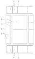
- FIG. 1 is a diagram showing an installation example of a smart wall of the present invention.
- FIG. 2 is an exploded perspective view of a smart wall according to an embodiment of the present invention.
- FIG. 3 is a block diagram of a smart wall according to an embodiment of the present invention.
- FIG. 4 is a diagram showing the configuration of a frame of a smart wall according to an embodiment of the present invention.
- FIG. 5 shows examples of various frame structures according to a combination of frame modules of the present invention.
- FIG. 6 is a diagram illustrating a frame module of a smart wall according to an embodiment of the present invention.
- FIG. 7 is a view for explaining a method of installing a frame structure of a smart wall according to an embodiment of the present invention.
- FIG. 8 is a view for explaining a basket of a smart wall according to an embodiment of the present invention.
- FIG. 9 is a diagram illustrating a change in an area in which a display unit is exposed on the front side of a smart wall according to an embodiment of the present invention.
- FIG. 10 is a diagram illustrating a screen disposed on a frame structure of a smart wall according to an embodiment of the present invention.
- FIG. 11 is a view showing a driving unit according to an embodiment of the present invention.
- FIG. 12 is a view showing a rear surface of a screen according to an embodiment of the present invention.
- FIG. 13 is a diagram showing the structure of a mesh according to an embodiment of the present invention.
- FIG. 14 is a cross-sectional view taken along line A-A of FIG. 12.
- FIG. 15 is a diagram illustrating a screen disposed on a frame structure of a smart wall according to an embodiment of the present invention.
- 16 is a diagram showing a driving unit of a smart wall according to an embodiment of the present invention.
- 17 is a view showing a driving unit of a smart wall according to another embodiment of the present invention.
- FIG. 18 is a diagram illustrating a timing chain and a connector of a screen according to an embodiment of the present invention.
- FIG. 19 is a view showing a screen and a driving unit disposed on a frame structure of a smart wall according to an embodiment of the present invention.
- FIG. 20 is a side view of the structure of FIG. 19.
- 21 is a diagram illustrating a driving unit of a screen according to an embodiment of the present invention.
- FIG. 22 is a view showing a driving unit of a screen according to another embodiment of the present invention.
- FIG. 23 is a view showing a closed band and a fastener of a screen according to another embodiment of the present invention.
- FIG. 1 is a view showing a wall-shaped frame of the smart wall 100 of the present invention.
- the present invention relates to a smart wall 100 in which electronic devices used at home, such as media devices and home appliances, are integrated on a wall so that they are not exposed to the exterior.
- electronic devices such as display unit, interphone, speaker, air purifier, humidifier, lighting, digital clock, router, and set-top box are mounted on the wall to provide a space total solution that minimizes exposure of electronic devices in the space.
- the thickness of the smart wall 100 of the present invention can be formed to be as thin as 15 to 20 cm, so that the indoor space can be prevented from narrowing during installation. Rather, storage furniture and home appliances 160 may be embedded in the smart wall 100 to provide a neat appearance. If necessary, a part of the wall may be selectively pulled out so that the necessary home appliance may protrude, and the space where the home appliance is not buried may be utilized as a mounting space 114 such as a drawer.
- a TV can be made thinner in recent years, and thus a thin display unit can be implemented.
- the TV itself serves as a cover for the frame and can be combined with the frame to form a front appearance.
- An opening 153 may be formed in the art wall 151 to expose the display portion of the display device 161, and a cover for opening and closing the opening 153 may be further provided.
- the display unit using OLED Since the display unit using OLED is bent, it is exposed to the outside only when in use, and when not in use, it can be rolled up and stored inside the wall, thus providing a clean screen in appearance.
- the projector As for the projector, a short throw projector was recently developed, and a large screen can be realized by mounting the projector on a wall, drawing it out in the form of a drawer, and outputting it to the screen. In this case, when not in use, the display unit is not visible on the outside of the smart wall 100 and thus a cleaner appearance can be provided.
- FIG 2 is an exploded view of the smart wall 100 of the present invention
- Figure 3 is a block diagram of the smart wall 100 of the present invention
- the interior of the front art wall 150 is a plurality of shape steel 115 (shape steel ) Can be placed in a frame structure arranged in a grid.
- the frame structure 110 is a rigid member and may be supported so as not to collapse even when an impact is applied to the wall.
- the electronic product 160 mounted on the frame structure 110 may be hidden and configured to appear as a wall.
- the front wall covered with such a panel is referred to as an art wall 150.
- the art wall 150 can be changed differently according to a consumer's taste. You can easily change it after installation to change the atmosphere of your home.
- the section steel 115 arranged in a grid form may partition the mounting space 114 and place the electronic product 160 in each mounting space 114.
- Each of the mounting spaces 114 may have the same size or multiple sizes, so that the mounted electronic product 160 may be modularized and disposed at any position in the frame structure 110.
- a sound device 162 such as a speaker may be mounted in the mounting space 114, and the sound device 162 may be configured in a plurality according to the number of channels.
- the art wall 152 covering the sound device 162 may be configured in a mesh shape to output sound or selectively open and close an opening through which sound is output to minimize an opening exposed to the art wall 152. Water may be prevented from flowing through the opening by using a waterproof mesh or the like.
- Seasonal household appliances such as a dehumidifier 163, a humidifier 165, an air purifier 164, and an air conditioner, such as an air conditioner and a heater 167 may be provided.
- Such seasonal home appliances are generally exposed to the outside when they are not in use, and dust accumulates and looks bad, so it is common to put a cover on it or put it in a warehouse.
- the art wall 150 can cover it so that it is not exposed to the outside even if it is left as it is even when not in use. That is, a separate storage space is provided for seasonal appliances. There is no need to do it.
- the dehumidifier 163 or the humidifier 165 may implement a drawer-type space for collecting/storing water to remove collected water or fill water.
- An opening 154 through which air passes in order to discharge water or collect moisture around it is required.
- the gap between the art wall 150 and the frame structure 110 can be used.
- the air purifier 164 may be provided with a cover that can be opened and closed so that the filter can be periodically replaced.
- Each electronic product may be individually controlled, but may further include a controller 180 for integrally controlling the electronic product mounted on the smart wall.
- the control unit may itself include the memory 185 to store the collected data.
- a dehumidifier, a humidifier, and an air purifier 164 can be installed at the bottom of the smart wall 100 so that the user can easily operate it.
- a set-top box or a WIFI router 175 when a set-top box or a WIFI router 175 is mounted, a home network system can be implemented. I can. Through the WIFI router 175, not only the functional units mounted on the smart wall 100, but also other electronic devices such as a computer or portable terminal located outside the smart wall 100 can be connected and interworked with each other, and the smart wall 100 It may include a controller 180 that controls each electronic product 160 mounted on the device.
- An LED or a small display panel may be disposed on the upper part of the smart wall 100 to provide simple information such as weather and time event information to the user, or may be used as lighting. By arranging lighting on the smart wall 100 itself, it is possible to add an interior effect.
- the router 175 is an intermediate device through which the router organizes and guides the route when different communication methods or signals are used.
- the functional unit mounted on the smart wall 100 may not necessarily be connected by wire, but may be connected and controlled through the WIFI router 175.
- the router 175 plays a role of connecting the external network and the internal network at the same time, the user can access the home network as well as the electronic product 160 mounted on the smart wall 100 through the router 175 connected to the external network. You can control other home appliances and media devices connected to it.
- the controller 180 may control electronic devices of the smart wall 100 in connection with a mobile device.
- a mobile device when a mobile device is mounted on the smart wall 100, media images and music from the mobile device are output, or when a video call is received through the mobile device, information of the mobile device is transmitted through Bluetooth or Wi-Fi. An image of the other party may be output to the display device 161 of ).
- a wall pad connected to a camera or method system at the entrance may be provided in the mounting space 114 of the smart wall 100.
- Wall pads that have been buried in the existing bearing wall are difficult to repair and replace, and have difficulties such as change of location in case of failure.
- the wall pad is configured in a unit form and provided in the smart wall 100, there is an advantage of easy maintenance.
- the smart wall 100 can be installed not only in the living room but also in the room. By configuring the walls between the rooms as the smart wall 100, the smart wall 100 may be used in both directions in neighboring rooms. For example, if one air conditioner or air purifier is passed in both directions, it can be used in both spaces. Instead of the TV and speaker 162 used in the living room, a monitor and a PC may be mounted and used according to the purpose of the room. Alternatively, other functional units such as an electronic blackboard may be mounted and used according to the child's age.
- the smart wall 100 When installed in an office, the smart wall 100 equipped with functional units such as an electronic blackboard, air purifier, video conference system, and PC can be used. Since the electronic product 160 mounted on the smart wall 100 is covered by the art wall 150, a separate exterior case is not required.
- the smart wall 100 is manufactured according to the user's installation location at the factory and then installed, the same module can be manufactured and supplied on a large scale when constructing a hotel/resort or apartment, reducing the defect rate and producing it at low cost.
- the assembled smart wall 100 is difficult to transport, and when the building is completed, it is difficult to carry it into the building. Therefore, when the smart wall 100 is installed when moving or interior in an existing building, the smart wall 100 can be implemented by installing a frame in the building and inserting a unit module. In this case, for ease of installation and standardization, the frame structure 110 may be implemented using a plurality of module frames.
- FIG. 4 shows a method of combining frame modules 111, 112, and 113 of the smart wall 100 according to an embodiment of the present invention.
- the frame modules 111, 112, and 113 in the form of a bookshelf including the mounting space 114 may be used.
- Frame modules 111, 112, and 113 may be manufactured by arranging a plurality of beam-shaped beams 115 in a grid to partition the mounting space 114.
- the frame modules 111, 112, 113 are a first frame module 111 in which the mounting spaces 114 are arranged side by side in a horizontal direction, and a second frame module for mounting a large product 160 such as a display device 161 It may include a third frame module 113 in which 112 and the mounting space 114 are arranged side by side in the vertical direction.
- the second frame module 112 includes a large space so that all of the display devices 161 can be mounted regardless of the inch. If necessary, as shown in FIG. 4, the display device 161 may be fixed by providing a beam that partitions the mounting space 114 and the rigidity of the frame structure 110 may be improved.
- the first frame module 111 may be stacked and disposed vertically with the second frame module 112.
- the length of the first frame module 111 in the horizontal direction may be the same as the length of the second frame module 112 in the horizontal direction, so that the grid may not be displaced when stacked in the vertical direction.
- the first frame module 111 may be disposed on the upper side and the lower side of the second frame module 112, respectively, and according to the size of the first frame module 111 and the second frame module 112 or the size of the installation space. Accordingly, the number of stacked first frame modules 111 in the vertical direction may be increased or decreased.
- the third frame module 113 in which the mounting spaces 114 are arranged side by side in the vertical direction may have the same height as the first frame module 111 and the second frame module 112 stacked in the vertical direction.
- the third frame module 113 may be located in the lateral direction of the first frame module 111 and the second frame module 112 as shown in FIG. 4.
- a plurality of frame modules 111, 112, 113 may be combined with fasteners to form a rectangular parallelepiped frame structure 110.
- FIG. 5 is a diagram showing a method of manufacturing the frame modules 111, 112, and 113 of the present invention, and a third frame module 113 in which the mounting space 114 is disposed in a vertical direction will be described as an example.
- Each of the frame modules 111, 112, and 113 may use a section steel 115 that is elongated in one direction.
- Shape steel is a structural member and collectively refers to a rod-shaped member having various cross-sectional shapes. It is possible to construct a column-shaped section steel having the same cross section in the longitudinal direction by rolling or bending the plate. Section steel has an advantage of being able to obtain rigidity of a certain size or more with lighter and less material since it has an empty space compared to a beam-shaped member having a circular or square cross section.
- the present invention may use a C-beam 115 having a C-shaped cross section as shown in FIG. 5.
- the C-beam 115 may be formed by vertically bending both ends of a metal plate in the width direction. If both ends are vertically bent only once, they have a C-shaped cross section, and if they are vertically bent twice, they can have a C-shaped cross-section.
- a power or signal line connected to the electronic product 160 may be disposed in the internal space, and an outlet module 140 to which power or data cables are connected may be disposed.
- the outlet module 140 may include a power terminal for supplying power, a data terminal for transmitting and receiving data such as an Internet line or cable input, and a connector for connecting a functional unit inserted in the frame with another functional unit.
- the connector has terminals on both sides of the frame, and data can be exchanged with each other by inserting a data connection line of each electronic device into the terminal.
- the outlet module 140 may include a rail structure that moves along the frame modules 111, 112 and 113.
- a vent hole 116 may be formed in the section steel 115.
- the vent hole 116 may reduce the weight of the section steel 115 and discharge heat generated from the electronic product 160.
- a fan can be used to discharge hot air to the outside.
- a heating effect can be obtained in winter.
- a structure that discharges heat to the outside can be added by circulating heat inside by using a fan as a cause of increasing the indoor temperature or by adding to the wiring connected to the outdoor unit of the air conditioner.
- Each of the frame modules 111, 112, and 113 may include an outer cavity forming a square around the outer circumference and an inner cavity for partitioning the mounting space 114 therebetween.
- the outer steel may include a vertical steel extending in a vertical direction and a horizontal steel extending in a horizontal direction.
- the first frame module 111 to the third frame module 113 may be assembled by arranging a horizontal steel between a pair of vertical steels. In order to fasten the vertical steel with the fixing member 120 fixed to the ceiling and the floor, it is necessary to arrange the upper and lower ends of the vertical steel to be exposed. Therefore, by positioning the vertical steel outside the horizontal steel, it is possible to insert and fasten the vertical brackets 122 and 123 of the fixing member 120 to the end of the vertical steel.
- the inner steel located inside the outer steel divides the space surrounded by the outer steel to form the mounting space 114, and the inner steel may be assembled so that it cannot be moved by welding to the outer steel, and some inner steels can be assembled using bolts or hooks. They can be combined so that they can be removed as needed.
- the number of assembly at the site can be minimized.
- the dimensions of the product 160 can be kept constant and installation time can be reduced.
- it can be modularized into a size that is easy to move, so it can be easily transported to the site.
- 6 shows examples of various frame structures 110 according to a combination of frame modules 111, 112, and 113 of the present invention.
- 6A is a frame structure 110 in which a pair of first frame modules 111a, one second frame module 112a, and a pair of third frame modules 113 of FIG. 4 are assembled. ). Since the first frame module 111a has four mounting spaces 114, it may be difficult to install in a narrow indoor space due to its wider width.
- a first frame module 111b having a short horizontal length including three mounting spaces 114 may be used.
- the second frame module 112b may have a length corresponding to the horizontal length of the first frame module 111b.
- the third frame module 113 may be disposed on both sides of the first frame module 111 and the second frame module 112 vertically stacked. Since the floor height of a typical house is 220cm ⁇ 230cm, the height of the third frame module 113 may be configured to be a little less than 220cm. Although a five-stage vertical frame is shown in the drawing, a six-stage vertical frame may also be manufactured in case of a double layer or high floor height.
- the third frame module 113 may be omitted and the frame structure 110 may be configured using only the first frame module 111a and the second frame module 112a, or a large display device ( If 161 is not mounted, the frame structure 110 may be implemented by arranging only the third frame in a line.
- Each frame module 111, 112, 113 may be fastened with bolts or may be fastened by welding.
- the frame structure 110 formed by fastening the frame modules 111, 112, and 113 may be fixed to the ceiling and the floor for installation in an indoor space.
- the fixing bracket 125 installed on the ceiling or floor is a member that is bent in an L-shape, and one side 125b extends in a vertical direction from the ceiling or floor and the other side 125a from the ceiling or floor.
- the first frame module 111 and the second frame module 112 may include a first vertical bracket 122 inserted into the inner space of the vertical cavity.
- the first vertical bracket 122 may be formed to be longer than the vertical length of the first frame module 111 so as to fasten not only the first frame module 111 but also the second frame module 112.
- a second vertical bracket 123 disposed parallel to the first vertical bracket 122 and inserted into the third frame module 113 may be further included. Since the vertical steel of the third frame module 113 is one member, it does not need to be as long as the first vertical bracket 122.
- the coupling bracket 121 coupled to the ends of the first vertical bracket 122 and the second vertical bracket 123 may form a T-shape together with the vertical brackets 122 and 123.
- the coupling bracket 121 is coupled to the vertical brackets 122 and 123, and is vertical from the seating portion 121b and the seating portion 121b that are seated on the upper surfaces of the first frame module 111 and the third frame module 113. It may include a fastening portion 121a extending in the direction and fastened with the fixing bracket 125.
- the coupling bracket 121 and the fixing bracket 125 may be fastened using a screw, and the fastener to which the screw is fastened may be formed to be long in the vertical direction so that it can be adjusted according to the ceiling height.
- the smart wall 100 When the smart wall 100 is installed by attaching it to an existing wall, it may further include a fixing member 120 fastened to the existing wall.
- the smart wall 100 Since the smart wall 100 has an audio device, such as the speaker 162, when it is used as a temporary wall, a space separated from the wall is generated. At this time, in order to block the sound of the two spaces, the smart wall 100 may be fixed by adding a soundproof structure so that sound does not leak to the ceiling, floor, and sidewalls in contact with the smart wall 100.
- the frame modules 111, 112, and 113 may be divided into a plurality of mounting spaces 114 using the inner section steel 115. As shown in FIG. 7, a space in which the electronic product 160 is mounted may be provided by inserting the basket 130 into the mounting space 114.
- the second frame module 112 has a relatively large mounting space 114 because the display device 161 is located, but the mounting space 114 of the first frame module 111 and the third frame module 113 is It can be formed in a standardized size. If the mounting space 114 of a standardized size is used, the basket 130 can also be standardized, and thus there is an advantage that there is no need to unnecessarily manufacture parts of various shapes.
- the size of the mounting spaces are all the same, it is convenient for standardization, but a larger space may be required depending on the electronic product 160 to be mounted.
- the size of the mounting space 114 may be formed to be an integer multiple of the basic size in consideration of this difference. For example, based on the first mounting space 1141 having a horizontal size of a and a vertical size of b, a second mounting space 1142 having an integer multiple of a horizontal size, or a third mounting space 1142 having an integer multiple of b vertical size It may include a mounting space (1143).
- the size in the horizontal direction of the first mounting space 1141 corresponds to the size in the horizontal direction of the third frame module 113 and the size in the vertical direction corresponds to the size in the vertical direction of the first frame module 111.
- the mounting space 114 means an internal space divided by the section steel 115, so the comparison between the size of the first frame module 111 and the size of the third frame module 113 is due to the thickness of the section steel 115 Is ignored.
- the first frame module 111 may include only the first mounting space 1141 and the second mounting space 1142, and the third frame module 113 has a short length in the horizontal direction. Therefore, only the first mounting space 1141 and the third mounting space 1143 may be included.
- FIG. 9 is a diagram illustrating a change in an area in which the display device 161 is exposed on the front of the smart wall 100 according to an embodiment of the present invention
- FIG. 10 is a smart wall according to an embodiment of the present invention.
- the frame structure 110 may include a plurality of mounting spaces.
- the frame structure 110 may include a plurality of mounting spaces, of which a display device may be mounted in a mounting space of a third frame module.
- a screen 200 covering the display device 161 may be included. If a screen 200 similar to the art wall 150 is used, a continuous wall surface can be produced.
- FIG. 9(a) If necessary, only half of the display device 161 is exposed as shown in FIG. 9(a) to provide necessary information to the user. As shown in FIG. 9(b), the interior effect is usually exposed in a small size. You can also get it.
- the smart wall 100 of the present invention may include a screen 200 that selectively covers the front surface of the display device 161 in order to selectively expose the display device 161 as described above.
- the screen 200 may use a material that is bent, such as a fabric material, and covers the front surface of the display device 161 and serves to hide the display device 161 from being exposed to the outside when the display device 161 is not used. .
- a part of the screen 200 (a first area) is located in front of the display device 161 by winding the screen 200 half a turn around the driving roller 210, and a part of the screen 200 (a second area) is a display device. It can be configured to be located on the back of (161). When the area of the second area of the screen 200 located at the rear of the display device 161 is increased, the area of the first area of the screen 200 located at the front of the display device 161 decreases. The area exposed on the front surface of the display device 161 may be adjusted by adjusting the area of the screen 200 located thereon.
- the area of the first area is increased to cover the display device 161 to minimize the structure exposed to the front surface, and the area of the first area as shown in FIG. 9(b) or 1
- the display device 161 is exposed on the front surface.
- the second area is on the rear surface of the display device and is not exposed to the user.
- the controller 180 adjusts the area of the screen 200 located in front of the display device 161 by adjusting the rotation direction of the driving roller 210, and detects the position of the screen 200 so that the display device 161 You can control the location and area where the image of is displayed. Also, the controller 180 may stop the rotation of the driving roller 210 when the screen reaches a preset position using a sensor so that the screen stops at a desired position.
- the driving unit of the present invention transmits the rotational force of the motor 220 to the driving roller 210 to stably move the screen 100 up and down to adjust the area of the screen 100 located in front of the display device 161. Provides a structure that is there.
- 11 is a view showing a driving unit according to an embodiment of the present invention.
- 11A is a view showing an enlarged view of a driving unit including a driving roller 210 and a motor 220
- 11B is a driving roller 210, a timing belt 222, and a timing gear 221
- the driving unit of the present invention includes a motor 220, a timing gear 221 and a timing belt 222.
- the motor 220 is a device that provides rotational force, and the controller 180 may control the motor 220 to adjust the areas of the first area and the second area.
- the timing gear 221 that rotates by receiving the rotational force of the motor 220 has a plurality of first teeth formed along the outer periphery.
- the timing belt 222 having the second teeth meshing with the first teeth of the timing gear 221 is a belt-shaped member, and is coupled to the first surface of the screen 200 as shown in FIG. 11(b). do. Since the second side opposite to the first side is exposed to the outside and the first side is not exposed to the user, even if the timing belt 222 is coupled, the appearance is not affected.
- the timing belt 222 may include a soft material such as silicon so as to be wound along the timing gear 221, and when the timing belt 222 moves according to the rotation of the timing gear 221, the screen 200 also moves. I can. Force is transmitted to the entire area of the screen 200 so that the screen 200 can stably move.
- the timing gear 221 is connected to the driving roller 210 so that the rotation axis of the timing gear 221 and the rotation axis of the driving roller 210 coincide and rotate together. Since the driving roller 210 is not rotated by the movement of the screen, but the driving roller 210 itself is also rotated, the rotational force of the driving roller 210 is directly transmitted to the screen 200. That is, the screen may receive the rotational force of the motor 220 not only through the timing belt 222 but also through the driving roller 210.
- the surface of the driving roller 210 may be coated with a material having high friction so that the rotational force of the driving roller 210 is transmitted to the screen 200.
- a silicon or rubber material may be coated on the surface of the driving roller 210.
- the covering portion of the driving roller 210 may have a thickness corresponding to the thickness of the timing gear 221 and the timing belt 222 so as not to cause wrinkles on the screen 200.
- It may further include an auxiliary roller 325 disposed in parallel with the driving roller 210 so as to prevent wrinkles from occurring on the screen 200 and move together with the rotation of the driving roller 210 without the screen 200 being pushed. have.
- the auxiliary roller 325 extends in a direction parallel to the driving roller 210, and the screen 200 is inserted between the auxiliary roller 325 and the driving roller 210 and passes through the opposite direction of the rotation direction of the driving roller 210. It rotates and moves the screen 200 and may include a covering portion of an elastic material such as the driving roller 210 for frictional force with the screen 200.
- the auxiliary roller 325 holds the screen 200 in close contact with the driving roller 210 so that the screen 200 is not lifted or slipped, and may move in close contact with the driving roller 210.
- a first spur gear rotating together with the driving roller 210 and a second spur gear coupled to the auxiliary roller 325 are further provided. It is possible to provide a rotational force to the auxiliary roller 215.
- a pair of timing belts 222 may be positioned on both sides of the screen 200 in the horizontal direction. Since the timing gear 221 is coupled to both sides of the driving roller 210, the two timing gears 221 can be driven with one motor 220.
- the screen 200 is a load beam 209 extending in the horizontal direction to a lower portion of the first area located in front of the driving roller 210 so that the screen 200 can be maintained in a flat unfolded state. ) May be further included.
- the load beam 209 pulls the screen 200 downward, so that the lower part of the screen 200 is not lifted and the screen 200 can be spread flat, and the load beam 209 is provided with a plurality of load beams 209 as necessary to provide adequate force.
- the screen 200 can be pulled out.
- the load beam 209 may further reinforce the horizontal stiffness by forming a groove extending in the horizontal direction as shown in FIG. 12 for stiffness.
- the portion where the load beam 209 is positioned cannot be wound around the driving roller 210 and is always positioned in front of the display device 161. Accordingly, the timing belt 222 guiding the screen winding around the driving roller 210 is not located at the first lower side where the load beam 209 is located, but only needs to be located above it.
- a load beam 209 may also be provided in the second region to balance the force between the first region and the second region.
- the screen 200 of the present invention may include a first fabric 201 exposed to a user, and may include a metal mesh 203 positioned in the first surface direction of the first fabric 201.
- the metal mesh 203 includes a metal material such as SUS (Stainless Use Steel), and includes a plurality of mesh holes 203a. The stiffness may vary depending on the size of the holes in the mesh.
- the screen 200 of the present invention should maintain rigidity in the horizontal direction and be bent along the driving roller 210 in the vertical direction. That is, there is a difference in the required values of stiffness and ductility in the horizontal and vertical directions, and to satisfy this, the shape of the mesh hole 203a is extended longer in the horizontal direction than in the vertical direction as shown in FIG. 13 ( a 1 ⁇ a 2 ).
- the mesh hole 203a is elongated in the horizontal direction, the area in the horizontal direction of the metal portion that is bent when the screen 200 is bent in the vertical direction is reduced. Therefore, the metal hole extending long in the horizontal direction is advantageous for bending deformation in the vertical direction.
- a plurality of mesh holes 203a of the present invention are disposed in a vertical direction and a horizontal direction, and are disposed to deviate from neighboring mesh holes 203a in the vertical direction. That is, the mesh hole (203a) is located at a point different from the mesh hole (203a) adjacent in the vertical direction at the start and end points, so that the length (b 1 ) of the metal part extending in the vertical direction is the metal part extending in the horizontal direction Unlike and can be cut short.
- the mesh holes 203a are arranged side by side in the horizontal direction and shifted in the vertical direction, so that the ductility in the vertical direction of the screen 200 is maintained as much as possible, and the rigidity in the horizontal direction can be improved.
- FIG. 14 is a cross-sectional view taken along line A-A of FIG. 12. It is a cross-sectional view.
- a second fabric 202 positioned on the first side of the metal mesh 203 may be further included.
- the metal mesh 203 When the metal mesh 203 is exposed to the first surface, the metal mesh 203 directly contacts the surface in contact with the driving roller 210 and thus the driving roller 210 may be worn.
- the metal mesh 203 when the user's hand touches the metal mesh 203, there is a risk of injury. In order to prevent this, the first surface of the metal mesh 203 may be covered with the second fabric 202.
- FIG. 13 is a view in which the second fabric 202 is omitted to show the metal mesh 203, but as shown in FIG. 12, the first surface of the screen 200 is the second fabric 202 is a metal mesh 203 ) To cover the metal mesh 203 is not exposed.
- the size of the first fabric 201 is formed to be larger so that the stacked structure of the screen 200 is not exposed, and as shown in FIG. 14, it is configured to surround the end of the metal mesh 203.
- the end of the first fabric 201 is positioned in the direction of the first surface of the metal mesh 203, and the second fabric 202 is formed as small as the corresponding size to form the first fabric 201 and the second fabric 202. ) Can be configured not to overlap.
- FIG. 15 is a view showing a screen 200 disposed on the frame structure 110 of the smart wall 100 according to another embodiment of the present invention
- FIG. 16 is a view showing an enlarged driving part of FIG. 15 .
- the driving unit of the present invention includes a motor 220, a timing gear 221 and a timing chain 223.
- the motor 220 is a device that provides a rotational force
- the controller 180 controls the motor 220 to adjust the areas of the first area 200a and the second area 200b of the screen.
- the timing gear 221 that rotates by receiving the rotational force of the motor 220 has a plurality of first teeth formed along the outer periphery.
- the timing chain 223 in which the hole 223a meshing with the first teeth of the timing gear 221 is formed is a strip-shaped member and is disposed adjacent to the side direction of the screen 200 as shown in FIG. 16. Since the timing chain 223 is located in the lateral direction of the screen 200, it may be covered with an art wall so as not to be exposed to the user.
- the timing chain 223 moves while the hole 223a into which the first teeth are inserted moves when the timing gear 221 rotates. Since a portion in contact with the timing gear 221 forms a curved surface, but portions other than that form a straight line, the timing chain 223 may have a shape in which the curvature is variable.
- the timing chain 223 may be formed by connecting a plurality of unit chains including the holes 223a, or the timing chain 223 may be implemented by using a soft material such as silicon.
- the timing gear 221 is connected to the driving roller 210 so that the rotation axis of the timing gear 221 and the rotation axis of the driving roller 210 coincide and rotate together. Since the driving roller 210 is not rotated by the movement of the screen, but the driving roller 210 itself is also rotated, the rotational force of the driving roller 210 is directly transmitted to the screen 200. That is, the screen may receive the rotational force of the motor 220 not only through the timing belt 222 but also through the driving roller 210.
- the surface of the driving roller 210 may be coated with a material having high friction so that the rotational force of the driving roller 210 is transmitted to the screen 200.
- a silicon or rubber material may be coated on the surface of the driving roller 210.
- the covering portion of the driving roller 210 may have a thickness corresponding to the thickness of the timing gear 221 and the timing chain 223 so as not to cause wrinkles on the screen 200.
- It may further include an auxiliary roller 325 disposed in parallel with the driving roller 210 so as to prevent wrinkles from occurring on the screen 200 and move together with the rotation of the driving roller 210 without the screen 200 being pushed. have.
- the auxiliary roller 325 extends in a direction parallel to the driving roller 210, and the screen 200 is inserted between the auxiliary roller 325 and the driving roller 210 and passes through the opposite direction of the rotation direction of the driving roller 210. It rotates and moves the screen 200 and may include a covering portion of an elastic material such as the driving roller 210 for frictional force with the screen 200.
- the auxiliary roller 325 holds the screen 200 in close contact with the driving roller 210 so that the screen 200 is not lifted or slipped, and may move in close contact with the driving roller 210.
- the motor 220 may be disposed at a position coincident with the rotation axis of the timing gear 221, but if there is insufficient space to be disposed in the lateral direction as shown in FIG. 16, the motor 220 is disposed adjacent to the timing gear 221 and the spur gear
- the rotational force may be transmitted to the timing gear 221 by using 224.
- the second spur gear 2242 receiving the rotational force of the first spur gear 2241 coupled to the motor 220 rotates in the opposite direction to the first spur gear 2241, and the timing gear 221 is a second spur gear. Combine to rotate around the same axis of rotation as (2242).
- the timing gear 221 rotates in a direction opposite to the rotation direction of the motor 220.
- the second spur gear 2242 rotating together with the driving roller 210 and the third spur gear coupled to the auxiliary roller 325 ( 2243) may be further provided to provide rotational force to the auxiliary roller 215.
- a pair of timing chains 223 may be positioned on both sides of the screen 200 in the horizontal direction. Since the timing gear 221 is coupled to both sides of the driving roller 210, the two timing gears 221 can be driven with one motor 220.
- timing chain 223 In order for the timing chain 223 to be located on the rear surface of the art wall 150, it should be located in the rear direction of the smart wall 100 rather than the first area 200a of the screen. Since a screen wall having a cleaner appearance can be provided, the art wall 150 and the screen 200 are preferably disposed in the same plane.
- the diameter of the timing gear 221 is greater than the diameter of the driving roller 210 wound around the screen so that the timing chain 223 is located in the rear direction than the first area 200a of the screen 200 (at least as much as the thickness of the art wall). It can also be made small. However, in this case, the moving distance of the timing chain 223 wound around the timing gear 221 and the moving distance of the screen wound around the driving roller 210 may be different.
- the rotation speed may be changed in inverse proportion to the diameter ratio of the timing gear 221 and the drive roller 210 so that the moving distance between the timing chain 223 and the screen 100 is the same.
- FIG. 17 is a view showing a driving unit of the smart wall 100 according to another embodiment of the present invention.
- This embodiment is characterized in that the fourth spur gear 2244 is further added to solve a problem that occurs when the diameters of the driving roller 210 and the timing gear 221 are different as described above.
- a fourth spur gear 2244 having a smaller diameter than the second spur gear 2242 connected to the driving roller 210 and having a small number of teeth is further added, and a timing gear 221 is connected to the fourth spur gear 2244 to achieve a timing gear.
- the number of rotations of 221 may be increased more than that of the second spur gear 2242.
- the rotation speed of the timing gear 221 is a times larger than the rotation speed of the driving roller 210, and as a result, the timing The moving speed of the chain 223 and the screen is the same.
- the screen 200 is a load extending in the horizontal direction to the lower portion of the first area 200a located in front of the driving roller 210 so that the screen 200 is not lifted and maintained in a flat unfolded state. It may further include a beam 209.
- the load beam 209 pulls the screen 200 downward, so that the lower part of the screen 200 is not lifted and the screen 200 can be spread flat, and the load beam 209 is provided with a plurality of load beams 209 as necessary to provide adequate force.
- the screen 200 can be pulled out.
- the load beam 209 extends in the horizontal direction, bending in the horizontal direction can be minimized by the driving roller 210 at the top and the load beam 209 at the bottom.
- the load beam 209 may further reinforce the horizontal stiffness by forming a groove extending in the horizontal direction as shown in FIG. 18 for stiffness.
- the portion where the load beam 209 is positioned cannot be wound around the driving roller 210 and is always positioned in front of the display device 161.
- a load beam 209 may also be provided in the second region to balance the force between the first region and the second region.
- the load beam 209 is the opposite side of the second area 200b or the first area. It is provided in the region 200a and can balance the force with respect to the pulling force in the direction in which the connector 229 is coupled.
- a first connector 229a coupled to the first lower portion of the first region 200a to uniformly provide force to both sides of the first region 200a and the second region 200B.
- a second connector 229b coupled to the second lower portion of the second region 200b.
- the load beam 209 is also provided with both the first load beam 209a coupled to the first lower portion and the second load beam 209b coupled to the second lower portion, so that the first region 200a and the second region (200b) can maintain the power balance.
- FIG. 19 is a view showing a screen 200 and a driving unit disposed on the frame structure 110 of the smart wall 100 according to an embodiment of the present invention
- FIG. 20 is a side view of the structure of FIG. 19 to be.
- the driving roller 210 located on one side of the mounting space extends in the horizontal direction, and one driving roller 210 may be used, or as shown in FIG. 20, a pair is arranged side by side in the front and rear direction of the screen 200. It could be.
- a space between the first area 200a and the second area 200b of the screen 200 may be formed wide.
- a space in which the display device 161 is mounted can be sufficiently secured without increasing the diameter of the driving roller 210.
- a part of the screen 200 (the first area 200a) is located in front of the display device 161 by winding the screen 200 half a turn around the driving roller 210, and a part of the screen 200 (the second area ( 200b)) may be configured to be located on the rear surface of the display device 161.
- FIG. 19 is a view as viewed from the rear of the frame structure 110, wherein the first area 200a located on the side viewed by the user is located on the rear side of the drawing and the second area 200b located on the rear surface of the display device 161 It is located on the front side on this drawing.
- the area of the second area 200b of the screen 200 located at the rear of the display device 161 is increased, the area of the first area 200a of the screen 200 located at the front of the display device 161 is reduced.
- the area exposed on the front surface of the display device 161 may be adjusted by adjusting the area of the bar and the screen 200 positioned on the front and rear surfaces.
- the motor of the present invention is directly connected to the driving roller 210 and transmits a force to the screen 200 without rotating the driving roller 210 so that the screen 200 moves up and down, and the driving roller 210 is thus Can rotate.
- one end of the screen 200 may be moved in a vertical direction using a wire 226 connected to the second lower portion of the second area 200b of the screen 200.
- the motor 220 is located in the lower part of the mounting space, and at one end, the other end of the wire 226 is connected to the rotating part 225 that rotates when the motor 220 is driven, and the wire 226 is a rotating part according to the rotation of the rotating part 225. It is possible to control the vertical movement of the second region 200b of the screen 200 while being wound and unwound around the 225.
- a plurality of wires 226 may be provided in the horizontal direction so that the screen 200 is not inclined and both sides move uniformly, and the rotating part 225 connected to the motor 220 is formed to be long as shown in FIG. A plurality of wires 226 can be pulled or unrolled at the same time.
- a load beam 209 may be further provided on the first lower side of the first area 200a as shown in FIG. 19. I can.
- the load beam 209 may use a material having a large weight such as metal, and may provide a force to pull the first region 200a downward. That is, when the motor 220 is driven from the rotating part 225 in the direction in which the wire 226 is released, the screen 200 may naturally move the first lower side of the first region 200a downward.
- the load beam 209 extends in the horizontal direction, bending in the horizontal direction can be minimized by the driving roller 210 at the top and the load beam 209 at the bottom. By forming a groove extending in the horizontal direction in the load beam 209, it is possible to further reinforce the stiffness in the horizontal direction.
- the load beam 209 may be provided with a plurality of load beams 209 as necessary to pull the screen 200 with an appropriate force.
- FIG. 21 is a view showing a driving unit of the screen 200 according to an embodiment of the present invention.
- a slide member may be used to assist the movement of the screen 200 of the present invention.
- the rail 241 coupled to the vertical frame of the frame structure 110 extends in the vertical direction, and the bearing part 242 moving along the rail 241 may be coupled to the screen 200.
- a member capable of reducing frictional force such as the ball 243 may be interposed between the bearing part 242 and the rail 241.
- the bearing part 242 may assist in moving the first area 200a exposed to the user by being coupled to the first area 200a of the screen 200 in the vertical direction without distortion.
- a screen bracket 208 positioned at the first lower side of the screen 200 may be further included, and the bearing part 242 may be fastened to the screen bracket 208.
- the above-described load beam may be coupled to the screen bracket 208.
- a screen bracket 208 to fasten the rail 241 that does not overlap the screen 200 in the front-rear direction and the bearing part 242 moving on the rail 241 with the first area 200a of the screen 200 Silver may include a wing portion 208b extending in the lateral direction of the screen 200.
- the bearing part 242 is fastened to the wing part 208b, and the wing part 208b of the screen bracket 208 is the first lower part of the screen 200 as shown in FIG. 21 to be located on the rear surface of the art wall.
- the body portion 208aa coupled to and a step 208c may be formed.
- the wing portion 208b and the rail 241 are not exposed to the user, and the art wall and the screen 200 form the same plane. 208c) can be formed.
- FIG. 22 is a view showing a driving unit of the screen 200 according to another embodiment of the present invention
- FIG. 23 is a closed band 228 and fastener 229 of the screen 200 according to another embodiment of the present invention. It is a diagram showing.
- a rotary pulley 227 and a closed band 228 may be used as shown in FIG. 22.
- a pair of rotation pulleys 227 are arranged in an up-down direction, and the closed band 228 is coupled with a rotation pulley 227 so as to form a closed curve by contacting both ends thereof and to surround the pair of rotation pulleys 227.
- a pair of rotary pulleys are arranged in the lateral direction of the screen, that is, perpendicular to the screen, as shown in Fig. 22, and the closed band includes a portion positioned in the front and a portion positioned in the rear around the rotary pulley, such as a screen. .
- a motor 220 for transmitting power to the rotary pulley 227 may be included.
- a pair of rotary pulleys 227 may be provided on both sides of the screen 200.
- the rotary unit 225 connected to the pair of rotary pulleys 227 may be used.
- the spur gear 224 may be used to transmit the rotational force of the motor 220 to the rotation unit 225, and when the rotation unit 225 rotates, a pair of rotation pulleys 227 may rotate at the same time.
- the closed band 228 wound around the rotary pulley 227 is a first tooth on the surface of the rotary pulley 227 as shown in Fig. 23 (a) so that it is not pushed when the rotary pulley 227 is rotated and rotates at an accurate timing. Is formed and a second tooth may be formed on the inner side of the closed band 228 facing the rotary pulley 227.
- the screen 200 is combined with the closed band 228 to move vertically, and the degree of exposure of the display device 161 may be controlled.
- the closed band 228 may be fastened to the screen bracket 208 described above, and in particular, it may be fastened to the wing portion 208b of the screen bracket 208 extending in the lateral direction.
- the fastener 229 is coupled to the screen 200 and is coupled to the first bracket 229a located on one side of the closed band 228 and the other side of the closed band 228. It may include a second bracket (229b) disposed to face the first bracket (229a).
- the movement of the closed band 228 and the movement of the screen 200 may be synchronized by fastening the first bracket 229a and the second bracket 229b with a screw. Since there are teeth on the inner side of the closed band 228, the second bracket 229b may have irregularities corresponding to the second teeth.
- the first bracket (229a) is fastened to the wing portion (208b) of the screen bracket (208) on one side and the other side is fastened to the second bracket (229b), as shown in (b) of FIG. 23, and a closed band (228). ) Can be combined.
- One side of the screen bracket 208 is fastened to the bearing part 242 described above and the other side is fastened to the first bracket 229a to control the vertical movement of the screen 200.
- the second area 200b is also fastened with the closed band 228 to prevent the closed band 228 from moving.
- the screen 200 may move vertically at the same speed as the moving speed.
- the rotary pulley 227 and the closed band 228 provide power for the screen 200 to move in the vertical direction, and the rail 241 and the bearing unit 242 allow the screen 200 to move up and down without shaking in the front and rear or left and right directions.
Landscapes
- Engineering & Computer Science (AREA)
- Theoretical Computer Science (AREA)
- General Engineering & Computer Science (AREA)
- Computer Hardware Design (AREA)
- Physics & Mathematics (AREA)
- General Physics & Mathematics (AREA)
- Human Computer Interaction (AREA)
- Architecture (AREA)
- Structural Engineering (AREA)
- Civil Engineering (AREA)
- Electromagnetism (AREA)
- Mechanical Engineering (AREA)
- Power Engineering (AREA)
- Multimedia (AREA)
- Casings For Electric Apparatus (AREA)
- Devices For Indicating Variable Information By Combining Individual Elements (AREA)
Abstract
Cette invention concerne une paroi intelligente, comprenant : une structure de cadre comprenant une cellule de montage ; un dispositif d'affichage installé dans la cellule de montage ; un rouleau d'entraînement disposé au-dessus de la cellule de montage ; un écran qui est enroulé autour du rouleau d'entraînement et comprend une première partie côté inférieur située sur le côté avant du dispositif d'affichage et une seconde partie côté inférieur située sur le côté arrière du dispositif d'affichage ; et un moteur pour déplacer l'écran enroulé autour du rouleau d'entraînement, de façon à permettre à l'écran, qui recouvre la surface avant du dispositif d'affichage, de recevoir la force du moteur sans glissement afin d'être déplacé de façon stable vers le haut ou vers le bas.
Priority Applications (2)
| Application Number | Priority Date | Filing Date | Title |
|---|---|---|---|
| EP20851870.4A EP4015725A4 (fr) | 2019-08-14 | 2020-08-14 | Paroi intelligente |
| US17/634,718 US20220290805A1 (en) | 2019-08-14 | 2020-08-14 | Smart wall |
Applications Claiming Priority (8)
| Application Number | Priority Date | Filing Date | Title |
|---|---|---|---|
| KR1020190099234A KR20210020240A (ko) | 2019-08-14 | 2019-08-14 | 스마트 월 |
| KR10-2019-0099233 | 2019-08-14 | ||
| KR10-2019-0099235 | 2019-08-14 | ||
| KR1020190099233A KR20210020239A (ko) | 2019-08-14 | 2019-08-14 | 스마트 월 |
| KR10-2019-0099234 | 2019-08-14 | ||
| KR1020190099235A KR20210020241A (ko) | 2019-08-14 | 2019-08-14 | 스마트 월 |
| KR1020190101096A KR20210021755A (ko) | 2019-08-19 | 2019-08-19 | 스마트 월 |
| KR10-2019-0101096 | 2019-08-19 |
Publications (1)
| Publication Number | Publication Date |
|---|---|
| WO2021029762A1 true WO2021029762A1 (fr) | 2021-02-18 |
Family
ID=74571155
Family Applications (1)
| Application Number | Title | Priority Date | Filing Date |
|---|---|---|---|
| PCT/KR2020/095117 WO2021029762A1 (fr) | 2019-08-14 | 2020-08-14 | Paroi intelligente |
Country Status (3)
| Country | Link |
|---|---|
| US (1) | US20220290805A1 (fr) |
| EP (1) | EP4015725A4 (fr) |
| WO (1) | WO2021029762A1 (fr) |
Citations (6)
| Publication number | Priority date | Publication date | Assignee | Title |
|---|---|---|---|---|
| JPH06123919A (ja) * | 1992-10-12 | 1994-05-06 | Sony Corp | 映像システムのスクリーンユニット |
| US6125905A (en) * | 1997-08-26 | 2000-10-03 | Owens Corning Fiberglas Technology, Inc. | Protective coverings |
| KR200448707Y1 (ko) * | 2009-10-08 | 2010-05-11 | 민인영 | 텐션 기능을 갖는 차양장치 |
| KR101491104B1 (ko) * | 2014-06-17 | 2015-02-11 | 고구려시스템(주) | 방범용 방충문 구조체 |
| EP3239429A1 (fr) * | 2016-04-26 | 2017-11-01 | Giuseppe Genchi | Volet roulant avec des lames pivotables et système de déplacement associé |
| KR20190058799A (ko) * | 2017-11-22 | 2019-05-30 | 한국건설기술연구원 | 장력조절장치를 구비하는 롤 블라인드 |
Family Cites Families (11)
| Publication number | Priority date | Publication date | Assignee | Title |
|---|---|---|---|---|
| SE506048C2 (sv) * | 1996-02-07 | 1997-11-03 | Avi I Stockholm Ab | Filmduksanordning och förfarande för att bringa en filmduk i ett för visning av bilder lämpligt läge |
| US6257305B1 (en) * | 2000-04-14 | 2001-07-10 | Wayne-Dalton Corporation | Method and apparatus for driving and storing a covering |
| US6901987B1 (en) * | 2003-09-26 | 2005-06-07 | Jonathan W. Graham | Furled decorative covering apparatus and method |
| JP4836114B2 (ja) * | 2005-03-15 | 2011-12-14 | アルパイン株式会社 | モニタ装置 |
| KR200445370Y1 (ko) * | 2008-06-12 | 2009-07-22 | 윤종희 | 사면설치용 차양장치 |
| US20170321481A1 (en) * | 2015-02-12 | 2017-11-09 | Sina Ashkanmehr | Light adjustment system for a window |
| US11186070B2 (en) * | 2017-02-06 | 2021-11-30 | Hunter Douglas Inc. | Room darkening material and architectural covering made from same |
| CN207803838U (zh) * | 2017-09-13 | 2018-09-04 | 杭州汉世陶瓷有限公司 | 智能背景墙柜体 |
| CN208905463U (zh) * | 2017-10-30 | 2019-05-28 | 靓靓屋有限公司 | 一体式智能投影电视柜 |
| US11041339B2 (en) * | 2018-01-19 | 2021-06-22 | Robert Edward Miller | Portable wind and sun screen |
| US20200032581A1 (en) * | 2018-07-27 | 2020-01-30 | Joseph G. Englert, JR. | Variable Window Treatment |
-
2020
- 2020-08-14 WO PCT/KR2020/095117 patent/WO2021029762A1/fr unknown
- 2020-08-14 US US17/634,718 patent/US20220290805A1/en active Pending
- 2020-08-14 EP EP20851870.4A patent/EP4015725A4/fr active Pending
Patent Citations (6)
| Publication number | Priority date | Publication date | Assignee | Title |
|---|---|---|---|---|
| JPH06123919A (ja) * | 1992-10-12 | 1994-05-06 | Sony Corp | 映像システムのスクリーンユニット |
| US6125905A (en) * | 1997-08-26 | 2000-10-03 | Owens Corning Fiberglas Technology, Inc. | Protective coverings |
| KR200448707Y1 (ko) * | 2009-10-08 | 2010-05-11 | 민인영 | 텐션 기능을 갖는 차양장치 |
| KR101491104B1 (ko) * | 2014-06-17 | 2015-02-11 | 고구려시스템(주) | 방범용 방충문 구조체 |
| EP3239429A1 (fr) * | 2016-04-26 | 2017-11-01 | Giuseppe Genchi | Volet roulant avec des lames pivotables et système de déplacement associé |
| KR20190058799A (ko) * | 2017-11-22 | 2019-05-30 | 한국건설기술연구원 | 장력조절장치를 구비하는 롤 블라인드 |
Also Published As
| Publication number | Publication date |
|---|---|
| US20220290805A1 (en) | 2022-09-15 |
| EP4015725A1 (fr) | 2022-06-22 |
| EP4015725A4 (fr) | 2023-08-30 |
Similar Documents
| Publication | Publication Date | Title |
|---|---|---|
| WO2021066236A1 (fr) | Mur intelligent | |
| KR102650347B1 (ko) | 스마트 월 | |
| WO2021100915A1 (fr) | Paroi intelligente | |
| WO2014021495A1 (fr) | Dispositif de haut-parleur pour une télévision | |
| WO2017204453A1 (fr) | Mur préfabriqué pour intérieur et son procédé de construction | |
| WO2021029762A1 (fr) | Paroi intelligente | |
| WO2021100886A1 (fr) | Paroi intelligente et son procédé de commande | |
| KR20210004407A (ko) | 스마트 월 | |
| WO2021182659A1 (fr) | Paroi intelligente | |
| WO2021049697A1 (fr) | Purificateur d'air et paroi intelligente | |
| WO2021149850A1 (fr) | Mur intelligent | |
| WO2021182658A1 (fr) | Mur intelligent | |
| WO2021054504A1 (fr) | Paroi intelligente | |
| WO2021029474A1 (fr) | Mur intelligent | |
| WO2021117949A1 (fr) | Paroi intelligente et son procédé de commande | |
| KR20210051510A (ko) | 스마트 월 | |
| KR20210051511A (ko) | 스마트 월 | |
| KR20210020239A (ko) | 스마트 월 | |
| WO2021049696A1 (fr) | Purificateur d'air et paroi intelligente | |
| WO2021049695A1 (fr) | Purificateur d'air et paroi intelligente | |
| WO2021107186A1 (fr) | Paroi intelligente et procédé de commande associé | |
| KR20210020240A (ko) | 스마트 월 | |
| KR20210020241A (ko) | 스마트 월 | |
| KR20220009914A (ko) | 스마트 월 | |
| CN211831389U (zh) | 边框结构及多媒体系统 |
Legal Events
| Date | Code | Title | Description |
|---|---|---|---|
| 121 | Ep: the epo has been informed by wipo that ep was designated in this application |
Ref document number: 20851870 Country of ref document: EP Kind code of ref document: A1 |
|
| NENP | Non-entry into the national phase |
Ref country code: DE |
|
| ENP | Entry into the national phase |
Ref document number: 2020851870 Country of ref document: EP Effective date: 20220314 |