WO2021029363A1 - Pipe joint and tube with pipe joint - Google Patents
Pipe joint and tube with pipe joint Download PDFInfo
- Publication number
- WO2021029363A1 WO2021029363A1 PCT/JP2020/030385 JP2020030385W WO2021029363A1 WO 2021029363 A1 WO2021029363 A1 WO 2021029363A1 JP 2020030385 W JP2020030385 W JP 2020030385W WO 2021029363 A1 WO2021029363 A1 WO 2021029363A1
- Authority
- WO
- WIPO (PCT)
- Prior art keywords
- thread
- fastening
- region
- tube
- test
- Prior art date
Links
- 238000007747 plating Methods 0.000 claims abstract description 160
- 239000010410 layer Substances 0.000 claims abstract description 115
- 239000011347 resin Substances 0.000 claims abstract description 64
- 229920005989 resin Polymers 0.000 claims abstract description 64
- HCHKCACWOHOZIP-UHFFFAOYSA-N Zinc Chemical compound [Zn] HCHKCACWOHOZIP-UHFFFAOYSA-N 0.000 claims abstract description 52
- 229910052725 zinc Inorganic materials 0.000 claims abstract description 52
- 239000011701 zinc Substances 0.000 claims abstract description 52
- 239000011247 coating layer Substances 0.000 claims abstract description 51
- -1 polyethylene Polymers 0.000 claims abstract description 18
- 239000004698 Polyethylene Substances 0.000 claims abstract description 17
- 229920000573 polyethylene Polymers 0.000 claims abstract description 17
- 239000000314 lubricant Substances 0.000 claims abstract description 15
- 239000002245 particle Substances 0.000 claims abstract description 13
- 239000007787 solid Substances 0.000 claims abstract description 13
- 238000012360 testing method Methods 0.000 claims description 110
- 230000013011 mating Effects 0.000 claims description 75
- 239000000126 substance Substances 0.000 claims description 26
- 229910052751 metal Inorganic materials 0.000 claims description 23
- 239000002184 metal Substances 0.000 claims description 23
- 230000009467 reduction Effects 0.000 claims description 18
- 230000008878 coupling Effects 0.000 claims description 12
- 238000010168 coupling process Methods 0.000 claims description 12
- 238000005859 coupling reaction Methods 0.000 claims description 12
- 238000003825 pressing Methods 0.000 claims description 12
- 239000000463 material Substances 0.000 abstract description 4
- 239000011248 coating agent Substances 0.000 description 30
- 238000000576 coating method Methods 0.000 description 25
- 238000000034 method Methods 0.000 description 17
- 238000006243 chemical reaction Methods 0.000 description 16
- 230000000875 corresponding effect Effects 0.000 description 15
- 230000007423 decrease Effects 0.000 description 15
- 238000003780 insertion Methods 0.000 description 12
- 230000037431 insertion Effects 0.000 description 12
- 230000002093 peripheral effect Effects 0.000 description 10
- 238000005259 measurement Methods 0.000 description 9
- 238000012545 processing Methods 0.000 description 7
- 229910000990 Ni alloy Inorganic materials 0.000 description 6
- 230000008859 change Effects 0.000 description 6
- QELJHCBNGDEXLD-UHFFFAOYSA-N nickel zinc Chemical compound [Ni].[Zn] QELJHCBNGDEXLD-UHFFFAOYSA-N 0.000 description 6
- 239000003960 organic solvent Substances 0.000 description 6
- 238000011156 evaluation Methods 0.000 description 5
- 239000007788 liquid Substances 0.000 description 5
- PXHVJJICTQNCMI-UHFFFAOYSA-N Nickel Chemical compound [Ni] PXHVJJICTQNCMI-UHFFFAOYSA-N 0.000 description 4
- 238000005520 cutting process Methods 0.000 description 4
- 238000009713 electroplating Methods 0.000 description 4
- 238000004519 manufacturing process Methods 0.000 description 4
- 230000008569 process Effects 0.000 description 4
- UHOVQNZJYSORNB-UHFFFAOYSA-N Benzene Chemical compound C1=CC=CC=C1 UHOVQNZJYSORNB-UHFFFAOYSA-N 0.000 description 3
- 229910000640 Fe alloy Inorganic materials 0.000 description 3
- 230000015572 biosynthetic process Effects 0.000 description 3
- 238000004140 cleaning Methods 0.000 description 3
- 238000003618 dip coating Methods 0.000 description 3
- KFZAUHNPPZCSCR-UHFFFAOYSA-N iron zinc Chemical compound [Fe].[Zn] KFZAUHNPPZCSCR-UHFFFAOYSA-N 0.000 description 3
- VYZAMTAEIAYCRO-UHFFFAOYSA-N Chromium Chemical compound [Cr] VYZAMTAEIAYCRO-UHFFFAOYSA-N 0.000 description 2
- VYPSYNLAJGMNEJ-UHFFFAOYSA-N Silicium dioxide Chemical compound O=[Si]=O VYPSYNLAJGMNEJ-UHFFFAOYSA-N 0.000 description 2
- 229910052804 chromium Inorganic materials 0.000 description 2
- 239000011651 chromium Substances 0.000 description 2
- 230000007797 corrosion Effects 0.000 description 2
- 238000005260 corrosion Methods 0.000 description 2
- NNBZCPXTIHJBJL-UHFFFAOYSA-N decalin Chemical compound C1CCCC2CCCCC21 NNBZCPXTIHJBJL-UHFFFAOYSA-N 0.000 description 2
- 238000001035 drying Methods 0.000 description 2
- 238000007654 immersion Methods 0.000 description 2
- 238000012423 maintenance Methods 0.000 description 2
- 230000007246 mechanism Effects 0.000 description 2
- 229910052759 nickel Inorganic materials 0.000 description 2
- 230000008520 organization Effects 0.000 description 2
- 230000000149 penetrating effect Effects 0.000 description 2
- 229920003023 plastic Polymers 0.000 description 2
- 239000004033 plastic Substances 0.000 description 2
- 238000005498 polishing Methods 0.000 description 2
- 230000008439 repair process Effects 0.000 description 2
- 239000007921 spray Substances 0.000 description 2
- 238000010998 test method Methods 0.000 description 2
- 229910052582 BN Inorganic materials 0.000 description 1
- PZNSFCLAULLKQX-UHFFFAOYSA-N Boron nitride Chemical compound N#B PZNSFCLAULLKQX-UHFFFAOYSA-N 0.000 description 1
- OKTJSMMVPCPJKN-UHFFFAOYSA-N Carbon Chemical compound [C] OKTJSMMVPCPJKN-UHFFFAOYSA-N 0.000 description 1
- ZOKXTWBITQBERF-UHFFFAOYSA-N Molybdenum Chemical compound [Mo] ZOKXTWBITQBERF-UHFFFAOYSA-N 0.000 description 1
- 229910052581 Si3N4 Inorganic materials 0.000 description 1
- 229910000831 Steel Inorganic materials 0.000 description 1
- RTAQQCXQSZGOHL-UHFFFAOYSA-N Titanium Chemical compound [Ti] RTAQQCXQSZGOHL-UHFFFAOYSA-N 0.000 description 1
- NRTOMJZYCJJWKI-UHFFFAOYSA-N Titanium nitride Chemical compound [Ti]#N NRTOMJZYCJJWKI-UHFFFAOYSA-N 0.000 description 1
- QCWXUUIWCKQGHC-UHFFFAOYSA-N Zirconium Chemical compound [Zr] QCWXUUIWCKQGHC-UHFFFAOYSA-N 0.000 description 1
- 239000000853 adhesive Substances 0.000 description 1
- 230000001070 adhesive effect Effects 0.000 description 1
- 238000005452 bending Methods 0.000 description 1
- 238000006757 chemical reactions by type Methods 0.000 description 1
- 229910017052 cobalt Inorganic materials 0.000 description 1
- 239000010941 cobalt Substances 0.000 description 1
- GUTLYIVDDKVIGB-UHFFFAOYSA-N cobalt atom Chemical compound [Co] GUTLYIVDDKVIGB-UHFFFAOYSA-N 0.000 description 1
- 150000001875 compounds Chemical class 0.000 description 1
- 230000001143 conditioned effect Effects 0.000 description 1
- 230000001276 controlling effect Effects 0.000 description 1
- 230000002596 correlated effect Effects 0.000 description 1
- 230000003247 decreasing effect Effects 0.000 description 1
- 238000013461 design Methods 0.000 description 1
- 238000009826 distribution Methods 0.000 description 1
- 230000005489 elastic deformation Effects 0.000 description 1
- 229910002804 graphite Inorganic materials 0.000 description 1
- 239000010439 graphite Substances 0.000 description 1
- 238000000227 grinding Methods 0.000 description 1
- 239000011133 lead Substances 0.000 description 1
- WPBNNNQJVZRUHP-UHFFFAOYSA-L manganese(2+);methyl n-[[2-(methoxycarbonylcarbamothioylamino)phenyl]carbamothioyl]carbamate;n-[2-(sulfidocarbothioylamino)ethyl]carbamodithioate Chemical compound [Mn+2].[S-]C(=S)NCCNC([S-])=S.COC(=O)NC(=S)NC1=CC=CC=C1NC(=S)NC(=O)OC WPBNNNQJVZRUHP-UHFFFAOYSA-L 0.000 description 1
- 238000000691 measurement method Methods 0.000 description 1
- 229910021645 metal ion Inorganic materials 0.000 description 1
- 239000000203 mixture Substances 0.000 description 1
- 238000012986 modification Methods 0.000 description 1
- 230000004048 modification Effects 0.000 description 1
- 229910052750 molybdenum Inorganic materials 0.000 description 1
- 239000011733 molybdenum Substances 0.000 description 1
- CWQXQMHSOZUFJS-UHFFFAOYSA-N molybdenum disulfide Chemical compound S=[Mo]=S CWQXQMHSOZUFJS-UHFFFAOYSA-N 0.000 description 1
- 229910052982 molybdenum disulfide Inorganic materials 0.000 description 1
- 238000000465 moulding Methods 0.000 description 1
- 238000002360 preparation method Methods 0.000 description 1
- 235000012239 silicon dioxide Nutrition 0.000 description 1
- 239000000377 silicon dioxide Substances 0.000 description 1
- HQVNEWCFYHHQES-UHFFFAOYSA-N silicon nitride Chemical compound N12[Si]34N5[Si]62N3[Si]51N64 HQVNEWCFYHHQES-UHFFFAOYSA-N 0.000 description 1
- 238000002791 soaking Methods 0.000 description 1
- 239000010959 steel Substances 0.000 description 1
- 238000004381 surface treatment Methods 0.000 description 1
- 229910052719 titanium Inorganic materials 0.000 description 1
- 239000010936 titanium Substances 0.000 description 1
- WFKWXMTUELFFGS-UHFFFAOYSA-N tungsten Chemical compound [W] WFKWXMTUELFFGS-UHFFFAOYSA-N 0.000 description 1
- 229910052721 tungsten Inorganic materials 0.000 description 1
- 239000010937 tungsten Substances 0.000 description 1
- 229910052720 vanadium Inorganic materials 0.000 description 1
- GPPXJZIENCGNKB-UHFFFAOYSA-N vanadium Chemical compound [V]#[V] GPPXJZIENCGNKB-UHFFFAOYSA-N 0.000 description 1
- PXXNTAGJWPJAGM-UHFFFAOYSA-N vertaline Natural products C1C2C=3C=C(OC)C(OC)=CC=3OC(C=C3)=CC=C3CCC(=O)OC1CC1N2CCCC1 PXXNTAGJWPJAGM-UHFFFAOYSA-N 0.000 description 1
- 229910052726 zirconium Inorganic materials 0.000 description 1
Images


Classifications
-
- F—MECHANICAL ENGINEERING; LIGHTING; HEATING; WEAPONS; BLASTING
- F16—ENGINEERING ELEMENTS AND UNITS; GENERAL MEASURES FOR PRODUCING AND MAINTAINING EFFECTIVE FUNCTIONING OF MACHINES OR INSTALLATIONS; THERMAL INSULATION IN GENERAL
- F16L—PIPES; JOINTS OR FITTINGS FOR PIPES; SUPPORTS FOR PIPES, CABLES OR PROTECTIVE TUBING; MEANS FOR THERMAL INSULATION IN GENERAL
- F16L19/00—Joints in which sealing surfaces are pressed together by means of a member, e.g. a swivel nut, screwed on or into one of the joint parts
- F16L19/02—Pipe ends provided with collars or flanges, integral with the pipe or not, pressed together by a screwed member
- F16L19/025—Pipe ends provided with collars or flanges, integral with the pipe or not, pressed together by a screwed member the pipe ends having integral collars or flanges
- F16L19/028—Pipe ends provided with collars or flanges, integral with the pipe or not, pressed together by a screwed member the pipe ends having integral collars or flanges the collars or flanges being obtained by deformation of the pipe wall
-
- F—MECHANICAL ENGINEERING; LIGHTING; HEATING; WEAPONS; BLASTING
- F16—ENGINEERING ELEMENTS AND UNITS; GENERAL MEASURES FOR PRODUCING AND MAINTAINING EFFECTIVE FUNCTIONING OF MACHINES OR INSTALLATIONS; THERMAL INSULATION IN GENERAL
- F16L—PIPES; JOINTS OR FITTINGS FOR PIPES; SUPPORTS FOR PIPES, CABLES OR PROTECTIVE TUBING; MEANS FOR THERMAL INSULATION IN GENERAL
- F16L19/00—Joints in which sealing surfaces are pressed together by means of a member, e.g. a swivel nut, screwed on or into one of the joint parts
- F16L19/06—Joints in which sealing surfaces are pressed together by means of a member, e.g. a swivel nut, screwed on or into one of the joint parts in which radial clamping is obtained by wedging action on non-deformed pipe ends
- F16L19/07—Joints in which sealing surfaces are pressed together by means of a member, e.g. a swivel nut, screwed on or into one of the joint parts in which radial clamping is obtained by wedging action on non-deformed pipe ends adapted for use in socket or sleeve connections
-
- B—PERFORMING OPERATIONS; TRANSPORTING
- B60—VEHICLES IN GENERAL
- B60T—VEHICLE BRAKE CONTROL SYSTEMS OR PARTS THEREOF; BRAKE CONTROL SYSTEMS OR PARTS THEREOF, IN GENERAL; ARRANGEMENT OF BRAKING ELEMENTS ON VEHICLES IN GENERAL; PORTABLE DEVICES FOR PREVENTING UNWANTED MOVEMENT OF VEHICLES; VEHICLE MODIFICATIONS TO FACILITATE COOLING OF BRAKES
- B60T17/00—Component parts, details, or accessories of power brake systems not covered by groups B60T8/00, B60T13/00 or B60T15/00, or presenting other characteristic features
- B60T17/04—Arrangements of piping, valves in the piping, e.g. cut-off valves, couplings or air hoses
- B60T17/043—Brake line couplings, air hoses and stopcocks
-
- F—MECHANICAL ENGINEERING; LIGHTING; HEATING; WEAPONS; BLASTING
- F16—ENGINEERING ELEMENTS AND UNITS; GENERAL MEASURES FOR PRODUCING AND MAINTAINING EFFECTIVE FUNCTIONING OF MACHINES OR INSTALLATIONS; THERMAL INSULATION IN GENERAL
- F16B—DEVICES FOR FASTENING OR SECURING CONSTRUCTIONAL ELEMENTS OR MACHINE PARTS TOGETHER, e.g. NAILS, BOLTS, CIRCLIPS, CLAMPS, CLIPS OR WEDGES; JOINTS OR JOINTING
- F16B33/00—Features common to bolt and nut
- F16B33/06—Surface treatment of parts furnished with screw-thread, e.g. for preventing seizure or fretting
-
- F—MECHANICAL ENGINEERING; LIGHTING; HEATING; WEAPONS; BLASTING
- F16—ENGINEERING ELEMENTS AND UNITS; GENERAL MEASURES FOR PRODUCING AND MAINTAINING EFFECTIVE FUNCTIONING OF MACHINES OR INSTALLATIONS; THERMAL INSULATION IN GENERAL
- F16B—DEVICES FOR FASTENING OR SECURING CONSTRUCTIONAL ELEMENTS OR MACHINE PARTS TOGETHER, e.g. NAILS, BOLTS, CIRCLIPS, CLAMPS, CLIPS OR WEDGES; JOINTS OR JOINTING
- F16B5/00—Joining sheets or plates, e.g. panels, to one another or to strips or bars parallel to them
-
- F—MECHANICAL ENGINEERING; LIGHTING; HEATING; WEAPONS; BLASTING
- F16—ENGINEERING ELEMENTS AND UNITS; GENERAL MEASURES FOR PRODUCING AND MAINTAINING EFFECTIVE FUNCTIONING OF MACHINES OR INSTALLATIONS; THERMAL INSULATION IN GENERAL
- F16B—DEVICES FOR FASTENING OR SECURING CONSTRUCTIONAL ELEMENTS OR MACHINE PARTS TOGETHER, e.g. NAILS, BOLTS, CIRCLIPS, CLAMPS, CLIPS OR WEDGES; JOINTS OR JOINTING
- F16B7/00—Connections of rods or tubes, e.g. of non-circular section, mutually, including resilient connections
- F16B7/04—Clamping or clipping connections
-
- F—MECHANICAL ENGINEERING; LIGHTING; HEATING; WEAPONS; BLASTING
- F16—ENGINEERING ELEMENTS AND UNITS; GENERAL MEASURES FOR PRODUCING AND MAINTAINING EFFECTIVE FUNCTIONING OF MACHINES OR INSTALLATIONS; THERMAL INSULATION IN GENERAL
- F16B—DEVICES FOR FASTENING OR SECURING CONSTRUCTIONAL ELEMENTS OR MACHINE PARTS TOGETHER, e.g. NAILS, BOLTS, CIRCLIPS, CLAMPS, CLIPS OR WEDGES; JOINTS OR JOINTING
- F16B7/00—Connections of rods or tubes, e.g. of non-circular section, mutually, including resilient connections
- F16B7/18—Connections of rods or tubes, e.g. of non-circular section, mutually, including resilient connections using screw-thread elements
-
- F—MECHANICAL ENGINEERING; LIGHTING; HEATING; WEAPONS; BLASTING
- F16—ENGINEERING ELEMENTS AND UNITS; GENERAL MEASURES FOR PRODUCING AND MAINTAINING EFFECTIVE FUNCTIONING OF MACHINES OR INSTALLATIONS; THERMAL INSULATION IN GENERAL
- F16L—PIPES; JOINTS OR FITTINGS FOR PIPES; SUPPORTS FOR PIPES, CABLES OR PROTECTIVE TUBING; MEANS FOR THERMAL INSULATION IN GENERAL
- F16L13/00—Non-disconnectible pipe-joints, e.g. soldered, adhesive or caulked joints
- F16L13/14—Non-disconnectible pipe-joints, e.g. soldered, adhesive or caulked joints made by plastically deforming the material of the pipe, e.g. by flanging, rolling
-
- F—MECHANICAL ENGINEERING; LIGHTING; HEATING; WEAPONS; BLASTING
- F16—ENGINEERING ELEMENTS AND UNITS; GENERAL MEASURES FOR PRODUCING AND MAINTAINING EFFECTIVE FUNCTIONING OF MACHINES OR INSTALLATIONS; THERMAL INSULATION IN GENERAL
- F16L—PIPES; JOINTS OR FITTINGS FOR PIPES; SUPPORTS FOR PIPES, CABLES OR PROTECTIVE TUBING; MEANS FOR THERMAL INSULATION IN GENERAL
- F16L19/00—Joints in which sealing surfaces are pressed together by means of a member, e.g. a swivel nut, screwed on or into one of the joint parts
- F16L19/02—Pipe ends provided with collars or flanges, integral with the pipe or not, pressed together by a screwed member
- F16L19/025—Pipe ends provided with collars or flanges, integral with the pipe or not, pressed together by a screwed member the pipe ends having integral collars or flanges
- F16L19/028—Pipe ends provided with collars or flanges, integral with the pipe or not, pressed together by a screwed member the pipe ends having integral collars or flanges the collars or flanges being obtained by deformation of the pipe wall
- F16L19/0286—Pipe ends provided with collars or flanges, integral with the pipe or not, pressed together by a screwed member the pipe ends having integral collars or flanges the collars or flanges being obtained by deformation of the pipe wall and being formed as a flange
-
- F—MECHANICAL ENGINEERING; LIGHTING; HEATING; WEAPONS; BLASTING
- F16—ENGINEERING ELEMENTS AND UNITS; GENERAL MEASURES FOR PRODUCING AND MAINTAINING EFFECTIVE FUNCTIONING OF MACHINES OR INSTALLATIONS; THERMAL INSULATION IN GENERAL
- F16L—PIPES; JOINTS OR FITTINGS FOR PIPES; SUPPORTS FOR PIPES, CABLES OR PROTECTIVE TUBING; MEANS FOR THERMAL INSULATION IN GENERAL
- F16L58/00—Protection of pipes or pipe fittings against corrosion or incrustation
- F16L58/18—Protection of pipes or pipe fittings against corrosion or incrustation specially adapted for pipe fittings
- F16L58/184—Protection of pipes or pipe fittings against corrosion or incrustation specially adapted for pipe fittings for joints in which sealing surfaces are pressed together by means of a member, e.g. a swivel nut, screwed on or into one of the joint parts
Definitions
- This disclosure relates to fittings and tubes with fittings.
- annular portion called an ISO flare or a double flare is formed on the terminal with the pipe joint mounted on the outer circumference of the tube. Since the annular portion protrudes outward in the pipe radial direction and is larger than the inner diameter of the pipe joint, the pipe joint is prevented from coming off toward the terminal side by the annular portion. Further, since the tube for automobile piping is bent according to the layout of the bottom of the vehicle, the bent portion of the tube prevents the pipe joint from coming off in the direction away from the terminal.
- the tube when fastening the pipe joint, the tube may rotate together with the pipe joint.
- the accompanying rotation occurs when the frictional force generated between the annular portion provided on the tube and the pipe joint exceeds the frictional force generated between the annular portion and the mating member.
- a rotation torque is generated in which the tube is twisted as a reaction force to prevent the rotation. If the accompanying torque is large, the tube will be damaged.
- the reaction force of the rotating torque acts in the direction of loosening the fastened pipe joint, so if the rotating torque remains while the tube is attached to the vehicle, the pipe joint will loosen due to the vibration of the vehicle. Trigger. Therefore, the upper limit of the rotating torque generated when the pipe joint is fastened is determined in consideration of the strength of the tube and the vibration of the vehicle.
- one object of the present disclosure is a pipe joint capable of obtaining an initial axial force that makes the rotating torque less than the upper limit value and suppressing the rate of decrease in the axial force low when fastening and releasing are repeated. And to provide tubes with fittings.
- the pipe joint of the present disclosure is attached to the outer periphery of a metal tube provided with an annular portion protruding outward in the pipe radial direction at the end, and is fastened to a mating member in a state of being in contact with the annular portion.
- a pipe joint capable of connecting the tube to the mating member which is provided on one end side of a threaded portion having a male screw that meshes with a female screw provided on the mating member and is tightened at the time of fastening.
- Each of the threaded portion, the head portion, and the contact portion is pierced by a through hole extending in a direction parallel to the traveling direction of the male screw at the time of fastening, and the threaded portion includes the layer.
- the male screw has an outer diameter of 9.53 to 14.0 [mm]
- the head has a first plane oriented in a direction opposite to the traveling direction and a second plane orthogonal to the first plane.
- the contact portion includes a contact surface that can contact the annular portion, has an inner diameter of 4.98 to 8.44 [mm], and includes a center line extending in the same direction as the through hole.
- the first thread is set as the first thread and the second thread is used.
- a screw thread is defined as a second thread
- a third thread is defined as a third thread
- a fourth thread is defined as a fourth thread.
- a set fourth region and a fifth region set on the contact surface of the contact portion are defined, and within each region of the first region to the fifth region, one region is set at intervals of 10 [ ⁇ m].
- the arithmetic average of the thickness of the zinc-based plating layer measured at seven points arranged in the direction is calculated for each of the first to fifth regions, and the five calculated values are X 1 , X 2 , X 3 , X 4 , Let it be X5, and in the cross section, the valley bottom between the second thread and the third thread, the peak of the third thread, the valley bottom between the third thread and the fourth thread, and Before When the four measured values obtained by measuring the thickness of the zinc-based plating layer at each of the peaks of the fourth thread are T 1 , T 2 , T 3 , and T 4 , (X 1 + X 2 + X 3 + X) When the value obtained by 4 + X 5 + T 1 + T 2 + T 3 + T 4 ) / 9 is defined as the joint average plating thickness t [ ⁇ m], 2.1 ⁇ t ⁇ 19.7 holds.
- the tube with a pipe joint of the present disclosure includes a metal tube having an annular portion protruding outward in the pipe radial direction at an end and a bent portion provided at a position away from the annular portion, and the annular portion and the tubular portion.
- a pipe joint capable of connecting the tube to the mating member by being attached to the outer periphery of the tube in a state of being prevented from coming off at the bent portion and being fastened to the mating member in a state of being in contact with the annular portion.
- the pipe joint is provided with a threaded portion having a male screw that meshes with a female screw provided on the mating member and one end side of the threaded portion, and is tightened at the time of fastening.
- Each of the threaded portion, the head portion, and the contact portion is pierced by a through hole extending in a direction parallel to the traveling direction of the male screw at the time of fastening, and the threaded portion includes the layer.
- the male screw has an outer diameter of 9.53 to 14.0 [mm]
- the head has a first plane oriented in a direction opposite to the traveling direction and a second plane orthogonal to the first plane.
- the contact portion includes a contact surface that can contact the annular portion, has an inner diameter of 4.98 to 8.44 [mm], and includes a center line extending in the same direction as the through hole.
- the first thread is set as the first thread and the second thread is used.
- a screw thread is defined as a second thread
- a third thread is defined as a third thread
- a fourth thread is defined as a fourth thread.
- a set fourth region and a fifth region set on the contact surface of the contact portion are defined, and within each region of the first region to the fifth region, one region is set at intervals of 10 [ ⁇ m].
- the arithmetic average of the thickness of the zinc-based plating layer measured at seven points arranged in the direction is calculated for each of the first to fifth regions, and the five calculated values are X 1 , X 2. , X 3 , X 4 , X 5, and in the cross section, the valley bottom between the second thread and the third thread, the peak of the third thread, the third thread and the fourth thread.
- annular portion projecting outward in the pipe radial direction is attached to the outer periphery of a metal tube provided at the end, and is fastened to the mating member in a state of being in contact with the annular portion.
- This is a pipe joint capable of connecting the tube to the mating member, and is provided on one end side of the threaded portion and a threaded portion formed with a male screw that meshes with the female screw provided on the mating member.
- a zinc-based plating layer provided on the threaded portion, the head portion, and the contact portion, and an outermost surface outside the zinc-based plating layer, which contains a polyethylene-based substance, a lubricant, and solid particles.
- a resin coating layer is provided, and each of the screw portion, the head portion, and the contact portion is pierced by a through hole extending in a direction parallel to the traveling direction of the male screw at the time of fastening, and the thread portion is formed.
- the male screw has an outer diameter of 9.53 to 14.0 [mm]
- the head has a first plane oriented in a direction opposite to the traveling direction and a first plane orthogonal to the first plane.
- the contact portion includes two planes, the contact portion includes a contact surface that can contact the annular portion, has an inner diameter of 4.98 to 8.44 [mm], and extends in the same direction as the through hole.
- the first thread is set as the first thread
- the second thread is defined as the second thread
- the third thread is defined as the third thread
- the fourth thread is defined as the fourth thread.
- the first thread of the head is defined.
- a fourth region set to flank and a fifth region set to the contact surface of the contact portion are defined, and an interval of 10 [ ⁇ m] is defined in each of the first region to the fifth region.
- the arithmetic average of the thickness of the zinc-based plating layer measured at seven points lined up in one direction is calculated for each of the first to fifth regions, and the five calculated values are X 1 , X 2 , X 3 , and X. 4.
- X 5 the valley bottom between the second thread and the third thread, the peak of the third thread, and the valley bottom between the third thread and the fourth thread in the cross section.
- the fastening test including the fastening operation of fastening to the test member and the releasing operation of loosening the fastening and releasing the coupling of the test tube after the fastening operation is repeated n times (provided that 1 ⁇ n ⁇ 6).
- the maximum axial force generated in the first fastening test is defined as the initial axial force F 1 [kN]
- the maximum axial force generated in the nth fastening test is defined as the nth axial force F n [kN].
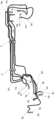
- the figure which showed the state which the pipe joint was attached and a plurality of bent brake tubes were assembled.
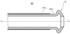
- the figure which showed the brake tube which ISO flare which is an example of an annular part was formed in the terminal.
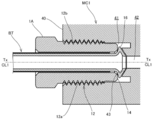
- the figure which showed the state which the brake tube was connected to the master cylinder which is an example of a mating member.
- the figure which showed the brake tube in which the double flare which is another example of an annular part was formed in a terminal.
- FIG. 6 is a cross-sectional view showing a part of a master cylinder which is an example of a mating member to which the brake tube of FIG. 7 is connected.
- FIG. 6 is an enlarged cross-sectional view of the IX portion of FIG.
- an automobile brake tube is used as a pipe for transmitting the pressure generated in the master cylinder to a brake unit provided for each wheel.
- an ABS unit or an ESC unit is provided from the master cylinder to the brake unit, and the brake tube is also used for connecting these units.
- a plurality of brake tubes having different pipe diameters are selected according to various conditions such as pressure resistance required between these units.
- a plurality of brake tube BTs are supplied to an automobile assembly line as an assembly product which is assembled by, for example, a resin clamp C and bent according to the bottom layout of the automobile.
- a double-wound tube made of a metal plate material such as a steel plate and having excellent pressure resistance is used in order to withstand the operating pressure of the brake.
- a tube having an outer diameter ⁇ in the range of 4.76 to 8.00 [mm] is selected.
- Each brake tube BT is fitted with a flare nut FN that matches its outer diameter.
- an operator collectively fastens the flare nut FN mounted on each brake tube BT to each of the above units with a common tightening torque specified in advance to collectively connect the brake tube BT.
- each brake tube BT is processed for high pressure with the flare nut FN attached.
- Terminal processing for high pressure includes terminal processing that forms an annular portion Rp such as ISO flare specified by the International Organization for Standardization (ISO) and double flare specified by the Japanese Automotive Standards Organization (JASO).
- Each brake tube BT is subjected to terminal processing for forming an annular portion Rp and bending processing for forming a bent portion Bp with the flare nut FN mounted on the outer periphery. Therefore, the flare nut FN is prevented from coming off from the brake tube BT by the annular portion Rp and the bent portion Bp provided at a position away from the annular portion Rp.
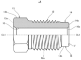
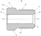
- FIG. 2 shows a flare nut 1A suitable for ISO flare.
- the flare nut 1A corresponds to an example of the pipe fitting of the present disclosure.
- the flare nut 1A is a hollow pipe joint having a through hole 10 into which a tube can be inserted.
- the flare nut 1A includes a threaded portion 12 on which a male screw 12a is formed, a head portion 13 provided on one end side of the threaded portion 12, and a contact portion 14 provided on the other end side of the threaded portion 12.
- the head 13, the screw portion 12, and the contact portion 14 are penetrated by a through hole 10 extending in the center line CL1 direction.
- the through hole 10 of the flare nut 1A shown in the figure has a shape having a constant inner diameter in the axial direction, but for example, instead of the through hole 10, the through hole has a stepped hole shape in which the inner diameter changes at a predetermined position in the axial direction. it can.
- the male screw 12a formed on the thread portion 12 is, for example, an ISO standardized metric coarse thread and meshes with the female thread 12b (see FIG. 4) formed on the mating member.
- the male screw 12a may be changed to a metric fine screw of the same standard as an example. Since the fine screw has a smaller lead angle than the coarse screw, it is possible to provide a flare nut that is more difficult to loosen with the same axial force by changing to the fine screw.
- the size of the screw portion 12 of the flare nut 1A applied to the brake tube BT described above the larger the outer diameter of the tube to be mounted, the larger the size of the screw tends to be adopted.
- the size of the threaded portion 12 is generally in the range of the nominal diameter of M10 to M14, that is, the outer diameter of 10.0 to 14.0 [mm].
- a screw having a nominal diameter in the range of 3/8 inch to 1/2 inch (about 9.53 to 12.7 [mm]) is adopted. Therefore, the male screw 12a that can be used for the flare nut 1A has an outer diameter in the range of 9.53 to 14.0 [mm].
- the head 13 is a portion where tightening torque is input at the time of fastening, and has a hexagonal shape standardized so that it can be fastened with a general tool such as a flare nut wrench.
- the head 13 includes a hollow circular flat surface 13a oriented in the axial direction and six side surfaces 13b with which the tools mesh.
- the flat surface 13a corresponds to an example of the first plane, and any one of the six side surfaces 13b corresponds to an example of the second plane.
- the size of the head 13 is selected according to the size of the screw portion 12, but unlike the case of the standardized bolt head, the size is standardized to some extent in order to reduce the number of tool changes.
- the contact portion 14 is provided at the right end of FIG. 2 along the center line CL1, in other words, at the end of the male screw 12a on the traveling direction side at the time of fastening.
- the contact portion 14 has a function of pressing the annular portion 16 against the mating member while contacting the annular portion 16 (see FIG. 3) formed as an ISO flare at the time of fastening to the mating member.
- the contact portion 14 includes a contact surface 14a that contacts the annular portion 16 and a cylindrical portion 14b that extends from the threaded portion 12 to the end side.
- a chamfered portion 10a inclined at about 45 ° with respect to the center line CL1 direction is provided at the boundary portion between the contact portion 14 and the through hole 10.
- the chamfered portion 10a alleviates the interference between the tube exterior and the flare nut 1A at the time of fastening and the stress concentration at the boundary portion between the through hole 10 and the contact portion 14.
- the chamfered portion 10a has a conical surface that appears in the cross section with respect to the center line CL1 and has a straight ridge line.
- a processed portion having a curved surface whose ridgeline is a curve drawn by one or a plurality of arcs that are convex toward the center may be provided.
- the inner diameter of the contact portion 14 is determined by the inner diameter of the through hole 10.
- the inner diameter d of the contact portion 14 is, for example, 4.98 [mm] when the outer diameter ⁇ of the brake tube BT is 4.76 [mm], and 6. when the outer diameter ⁇ is 6.0 [mm]. Set to 24 [mm], 6.59 [mm] when the outer diameter ⁇ is 6.35 [mm], and 8.29 [mm] when the outer diameter ⁇ is 8.0 [mm]. Will be done.
- the inner diameter d of the contact portion 14 allows an error of +0.15 [mm]. Therefore, the inner diameter d of the contact portion 14 that can be adopted for the flare nut 1A is in the range of 4.98 to 8.44 [mm].
- the annular portion 16 is formed at the end of the brake tube BT.
- An example of the formation procedure is as follows. First, the resin coating layer BTa of the brake tube BT is peeled from the terminal over a predetermined range in the tube axis Tx direction in the circumferential direction. Next, an ISO flare-shaped annular portion 16 is formed that projects outward in the pipe radial direction orthogonal to the pipe axis Tx with respect to the terminal portion of the peeled portion BTb from which the resin coating layer has been peeled off. Depending on the resin material of the resin coating layer BTa, the annular portion 16 may be formed with respect to the terminal portion of the brake tube BT without peeling off the resin coating layer BTa.
- the master cylinder MC1 which is an example of the mating member, has a housing 40.
- the housing 40 is formed with an insertion hole 41 into which the brake tube BT is inserted.
- the insertion hole 41 opens to the outside of the housing 40, and the opposite side of the opening communicates with the liquid passage 42 formed in the housing 40.
- the liquid passage 42 opens at the bottom 43 of the insertion hole 41.
- the bottom portion 43 is formed in a shape retracted toward the inside of the device so as to match the shape of the annular portion 16 of the brake tube BT.
- a female screw 12b that meshes with the male screw 12a of the flare nut 1A is formed on the inner peripheral surface of the housing 40 in which the insertion hole 41 is formed.
- the brake tube BT is inserted so that the annular portion 16 of the brake tube BT abuts on the bottom 43 of the insertion hole 41.
- the flare nut 1A is brought close to the insertion hole 16 and the male screw 12a of the screw portion 12 and the female screw 12b of the housing 40 are engaged with each other.
- the contact portion 14 comes into contact with the annular portion 16.
- the flare nut 1A is tightened while bringing the contact portion 14 into contact with the annular portion 16, the annular portion 16 is pressed against the bottom portion 43 by the contact portion 14.
- the annular portion 16 is sandwiched between the contact portion 14 and the bottom portion 43 and gradually deforms while shifting from elastic deformation to plastic deformation.
- the brake tube BT is liquid-tightly coupled to the master cylinder MC1.
- the coupling force of the brake tube BT is determined by the maximum axial force acting during such a fastening operation.
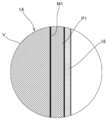
- the flare nut 1A is provided with a resin coating layer 18 in order to increase or stabilize the axial force at the time of fastening in order to firmly bond the brake tube BT.
- a zinc-based plating layer P1 is formed on the metal base M1.
- a resin coating layer 18 is provided on the plating layer P1.
- the resin coating layer 18 is located on the outermost outer surface of the plating layer P1. As long as the resin coating layer 18 is located on the outermost surface, for example, different types of resin layers may be provided between the plating layer P1 and the resin coating layer 18.
- zinc plating, zinc iron alloy plating, or zinc nickel alloy plating may be performed.
- a zinc-nickel alloy plating layer is provided as the plating layer P1.
- the plating layer P1 is provided on the entire surface of the metal base M1.
- the plating layer P1 covers the surfaces of the threaded portion 12, the head portion 13, and the contact portion 14, and the inner peripheral surface of the through hole 10 penetrating them.
- the plating layer P1 may be subjected to chemical conversion treatment.
- the plating layer P1 in this case includes a chemical conversion treatment layer on the outside thereof.
- the chemical conversion treatment layer enhances the adhesion between the plating layer P1 and the resin coating layer 18.
- the chemical conversion layer may contain metal atoms selected from titanium, zirconium, molybdenum, tungsten, vanadium, manganese, nickel, cobalt, chromium, and lead. In addition, some of these metal atoms may be contained in the chemical conversion treatment layer as compounds such as oxides.
- the chemical conversion treatment layer may be a chromium-free chemical conversion treatment layer.
- the chemical conversion treatment step for forming the chemical conversion treatment layer may be a reaction type or a coating type, and may be a trivalent chromium chemical conversion treatment or a chromium-free chemical conversion treatment.
- the plating layer P1 is formed by electrolytic plating.
- the untreated nut with the exposed metal base M1 is immersed in a plating bath containing zinc and nickel metal ions.
- the thickness of the coating deposited on the metal base M1 of the untreated nut is controlled by adjusting at least one of the current density and the processing time defined as the current per unit area during the plating process.
- the thickness of the film formed on the product to be plated is not uniform because the current density changes according to the shape of the product to be plated.
- the product to be plated includes not only parts with little shape change such as flat surface and cylindrical surface but also parts with large shape change such as convex corners and cusps on the surface side, the thickness of the coating at each part. Is different.
- the thickness of the plating layer P1 is different when the peak and the valley bottom of the thread of the threaded portion 12 are compared or when the peak and the contact surface 14a of the contact portion 14 are compared.
- the thickness of the plating layer P1 is compared between the peak of the thread of the threaded portion 12 and the contact surface 14a of the contact portion 14, the thickness of the peak tends to be smaller than that of the contact surface 14a. there were.
- the mechanical properties of the flare nut 1A change when the thickness of the plating layer P1 is different.
- the thickness of the plating layer P1 differs depending on the portion of the flare nut 1A, it is not possible to accurately evaluate the correlation between the thickness of the plating layer P1 and mechanical properties such as axial force. Therefore, the thickness of the plating layer P1 is quantitatively controlled or managed by using the joint average plating thickness described later calculated by a predetermined method.
- the resin coating layer 18 is formed in at least the coating region R (see FIG. 2) including the surfaces of the screw portion 12 and the contact portion 14.
- the coating region R is set on the entire surface of the flare nut 1A. That is, the coating region R is set on each surface of the threaded portion 12, the head portion 13 and the contact portion 14 of the flare nut 1A, and the inner peripheral surface of the flare nut 1A pierced by the through hole 10.
- the resin coating layer 18 contains a polyethylene-based substance, a lubricant, and solid particles.
- the resin coating layer 18 is formed by adhering a coating agent C containing these as a component to the coating region R.
- the polyethylene-based substance for example, polyethylene or a polyethylene copolymer can be selected.
- any one of polyethylene wax, molybdenum disulfide, graphite, or boron nitride, or any combination thereof can be selected.
- the lubricant may be solid or liquid.
- the fixed particles for example, any one of silicon dioxide, silicon nitride, or titanium nitride, or any combination thereof can be selected.
- the resin coating layer 18 is formed by a dip coating method as an example.
- the resin coating layer 18 may be formed by a spray method in which the coating agent is atomized and sprayed. This spray method is suitable for partially forming the resin coating layer 18 on the flare nut 1A.
- the friction coefficient of the resin coating layer 18 is smaller than the friction coefficient of the plating layer P1.
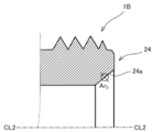
- FIG. 6 shows a flare nut 1B suitable for double flare.
- the flare nut 1B corresponds to an example of the pipe fitting of the present disclosure.
- the flare nut 1B is a hollow pipe joint having a through hole 20 into which a tube can be inserted.
- the flare nut 1B includes a threaded portion 22 on which a male screw 22a is formed, a head portion 23 provided on one end side of the threaded portion 22, and a contact portion 24 provided on the other end side of the threaded portion 22.
- the head 23, the screw portion 22, and the contact portion 24 are penetrated by a through hole 20 extending in the center line CL2 direction.
- the through hole 20 has a shape having a constant inner diameter in the axial direction, but for example, instead of the through hole 20, it can be changed to a stepped hole shape in which the inner diameter changes at a predetermined position in the axial direction. ..
- the male screw 22a formed on the screw portion 22 has the same specifications as the male screw 12a provided on the screw portion 12 of the flare nut 1A of the first form, and the male screw 22a that can be adopted as the flare nut 1B has an outer diameter thereof. It is in the range of 9.53 to 14.0 [mm]. Further, the specifications of the head 23 are the same as the specifications of the head 13 of the flare nut 1A.
- the head 23 includes a hollow circular flat surface 23a oriented in the axial direction and six side surfaces 23b with which the tool meshes.
- the flat surface 23a corresponds to an example of the first plane, and any one of the six side surfaces 23b corresponds to an example of the second plane.
- the specifications of the contact portion 24 are also the same as the specifications of the contact portion 14 of the flare nut 1A, and the contact portion 24 that can be adopted as the flare nut 1B has an inner diameter d within the range of 4.98 to 8.44 [mm]. is there.
- the contact portion 24 is provided at the right end of FIG. 6 along the center line CL2, in other words, at the end of the male screw 22a on the traveling direction side at the time of fastening.
- the contact portion 24 has a function of pressing the annular portion 26 against the mating member while contacting the annular portion 26 (see FIG. 7) formed as a double flare when the mating member is fastened.
- the contact portion 24 is provided near the end of the screw portion 22.
- There is no clear cylindrical portion such as the cylindrical portion 14b (see FIG. 2) of the flare nut 1A.
- a flare nut suitable for double flare there is also a flare nut including a cylindrical portion corresponding to the cylindrical portion 14b.
- the contact portion 24 has a conical contact surface 24a having an inclination angle of about 42 ° with respect to the axial direction.
- the annular portion 26 is formed at the end of the brake tube BT.
- An example of the formation procedure is as follows. First, the resin coating layer BTa of the brake tube BT is peeled from the terminal over a predetermined range in the tube axis Tx direction in the circumferential direction. Next, a double flare-shaped annular portion 26 is formed that projects outward in the pipe radial direction orthogonal to the pipe axis Tx with respect to the terminal portion of the peeled portion BTb from which the resin coating layer BTa has been peeled off. Depending on the resin material of the resin coating layer BTa, the annular portion 26 may be formed with respect to the terminal portion of the brake tube BT without peeling off the resin coating layer BTa.
- An insertion hole 51 having the structure shown in FIG. 8 is formed in the mating member to which the brake tube BT on which the annular portion 26 is formed is connected.
- the insertion hole 51 is formed in the master cylinder MC2, which is an example of the mating member.
- the insertion hole 51 opens to the outside of the housing 50, and the opposite side of the opening communicates with the liquid passage 52 formed in the housing 50.
- the liquid passage 52 opens to the bottom 53 of the insertion hole 51.
- the bottom portion 53 is formed in a shape protruding to the outside of the device so as to match the shape of the annular portion 26 of the brake tube BT.
- a female screw 22b that meshes with the male screw 22a of the flare nut 1B is formed on the inner peripheral surface of the housing 50 in which the insertion hole 51 is formed.
- the connection of the brake tube BT using the flare nut 1B is the same as that of the flare nut 1A, and thus the description thereof will be omitted.
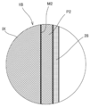
- the flare nut 1B is provided with a resin coating layer 28.
- a zinc-based plating layer P2 is formed on the metal base M2.
- a resin coating layer 28 is provided on the plating layer P2.
- the resin coating layer 28 is located on the outermost outer surface of the plating layer P2. As long as the resin coating layer 28 is located on the outermost surface, for example, different types of resin layers may be provided between the plating layer P2 and the resin coating layer 28.
- zinc plating, zinc iron alloy plating, or zinc nickel alloy plating may be performed. In this form, a zinc-nickel alloy plating layer is provided as the plating layer P2.
- the plating layer P2 is provided on the entire surface of the metal base M1.
- the plating layer P2 covers the surfaces of the threaded portion 22, the head portion 23, and the contact portion 24, and the inner peripheral surface of the through hole 20 penetrating them.
- the plating layer P2 may include a chemical conversion treatment layer on the outside. Similar to the first embodiment, for example, the plating layer P2 is formed by electrolytic plating, and the resin coating layer 28 is formed by a dip coating method. The friction coefficient of the resin coating layer 28 is smaller than the friction coefficient of the plating layer P2.
- the axial force at the time of fastening tended to decrease as the number of repetitions increased. Then, by the fastening test described below, it was found that the thickness of the zinc-based plating layer is a factor that affects the rate of decrease in axial force. Since no significant difference was found between the flare nut 1A and the flare nut 1B with respect to the test result of the fastening test, the test results of the flare nut 1A will be disclosed below.
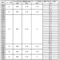
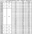
- Test sample (1) Preparation of test sample As shown in FIG. 10, a plurality of samples having different joint average plating thickness t [ ⁇ m], which will be described later, were prepared for three types of flare nuts having different shapes and sizes. .. A zinc-nickel alloy plating layer was adopted as an example of the plating layer of each sample. Further, the joint average plating thickness t was made different from each other by adjusting at least one of the current density and the processing time during the plating treatment of each sample. That is, the parameters that control the joint average plating thickness t are the current density and the processing time.
- the resin coating layer of each sample contains the above-mentioned polyethylene-based substance, lubricant, and solid particles, and one of two types of coating agents C1 and C2 having different viscosities at 25 [° C.] adheres to the coating region. It is formed by doing.
- a dip coating method was adopted as a method for forming the resin coating layer.
- the thickness was controlled by using the unit area mass w [g / m 2 ] described later, which correlates with the thickness.
- the unit area mass w of each sample is adjusted within the range of 0.79 ⁇ w ⁇ 10.07.
- the thickness of the plating layer Due to the characteristics of electrolytic plating, the thickness of the plating layer is not uniform depending on the flare nut part. It is known that the thickness of the plating layer affects the mechanical properties of flare nuts such as axial force. Therefore, the thickness of the plating layer is quantitatively controlled or controlled by using the joint average plating thickness t [ ⁇ m]. The average plating thickness t of the joint is calculated as follows.
- FIG. 11A shows a cross section of the flare nut 1A that passes through the center line CL1 and is orthogonal to any two of the six side surfaces 13b of the head 13.
- the average plating thickness t of the joint is calculated by measuring the thickness of the plating layer at each part appearing in this cross section.
- Second region Ar 2 The second region Ar 2 is a region set on the side surface 13b of the head 13. As shown in FIG.
- the second region Ar 2 when the distance to the end of the side surface 13b from the flat surface 13a and the L 2, with a focus on a position apart L 2/2 from the flat surface 13a radius It is set within a circle of 100 [ ⁇ m].
- B3 Third region Ar 3
- the third region Ar 3 is set within a circle having a radius of 100 [ ⁇ m] centered on the midpoint of the trailing flank of the third thread R 3 .
- Fourth region Ar 4 The fourth region Ar 4 is set within a circle having a radius of 100 [ ⁇ m] centered on the midpoint of the trailing flank of the fourth screw thread R 4 .
- (B5) Fifth region Ar 5 The fifth region Ar 5 is a region set on the contact surface 14a of the contact portion 14. As shown in FIG.
- the fifth region Ar 5 the distance from the center line CL1 to the inner peripheral surface of the through hole 10 (inner diameter of the contact portion 14) and r 51, the outer peripheral surface of the contact portion 14 from the center line CL1
- the first region Ar 1 to the fourth region Ar 4 are the same as the flare nut 1A, but the fifth region Ar 5 is set as shown in FIG. 11B.
- FIG. 11B the first region Ar 1 to the fourth region Ar 4 are the same as the flare nut 1A, but the fifth region Ar 5 is set as shown in FIG. 11B.
- 11B shows a part of a cross section of the flare nut 1B that passes through the center line CL2 and is orthogonal to any two of the six side surfaces 23b of the head 23.
- the fifth region Ar 5 is set within a circle having a radius of 100 [ ⁇ m] centered on the midpoint of the contact surface 24a of the contact portion 24 appearing in this cross section.
- each region Ar i which is set, as shown in FIG. 11C, measure the thickness of the plating layer at 107 points arranged in one direction in [[mu] m] interval p 1 ⁇ p 7 Then, the arithmetic mean of these seven measured values is calculated for each region A r i . As a result, five calculated values X 1 , X 2 , X 3 , X 4 , and X 5 corresponding to the five regions Ar i are acquired.
- the actual flare nut 1A or flare nut 1B is cut in the vertical direction with a cutting machine.
- the cutting position by the cutting blade is slightly offset in the radial direction from the center line so as not to be excessively polished beyond the center line of the actual product in the polishing step described later.
- the polishing allowance is secured and a measurement piece slightly larger than half can be obtained.
- the measuring piece is molded with resin so as to cover it. The orientation of the cut surface of the measurement piece should be known even after molding.
- the resin-molded measurement piece is surface-polished with a grinding machine until the cross section including the center line shown in FIG. 11A or FIG. 11B appears.
- each part of the polished cross section was imaged at a magnification of 1000 to 2500 times using the following digital microscope as an example, and the thickness of the plating layer was measured based on the captured image.
- the thickness of the resin coating layer correlates with the mass of the substance adhering to the coating region. Therefore, as a physical quantity that correlates with the thickness of the resin coating layer, a value obtained by dividing the mass difference between the presence and absence of the resin coating layer by the surface area of the coating region is defined as the unit area mass w [g / m 2 ]. The thickness of the resin coating layer was quantified using this unit area mass w.
- the unit area mass w was calculated by dividing the mass difference between the mass of the flare nut before the resin coating treatment and the mass of the flare nut after the formation of the resin coating layer by the total surface area of the flare nut. Contrary to this method, the unit area mass w is the mass difference between the mass of the flare nut on which the resin coating layer is formed and the mass of the flare nut after removing the resin coating layer, and is the total surface area of the flare nut. It may be calculated by dividing by. As a method for removing the resin coating layer, for example, after immersing the flare nut on which the resin coating layer is formed in a high-temperature organic solvent, the flare nut after immersion is washed with an organic solvent separately prepared for cleaning and dried. There is a way.
- an organic solvent capable of dissolving polyethylene such as benzene and decalin can be used as the organic solvent for immersing the flare nut.
- the soaking time and drying time are set to such an extent that they can be identified with flare nuts before the resin coating treatment.
- the immersion time in the organic solvent may be 5 hours, and the drying time may be 1 hour after cleaning with the organic solvent for cleaning.
- the flare nut from which the resin coating layer has been removed by this treatment can be equated with the flare nut before the resin coating treatment.
- the total surface area of the flare nut was calculated using the surface area calculation function attached to the CAD software based on the flare nut design drawing data. By using this function, the surface area can be calculated for any range of flare nuts. Although there may be a slight difference in the calculated surface area depending on the CAD software, the difference can be ignored in the calculation of the unit area mass w calculated with two digits after the decimal point. Further, the error between the calculated value by the CAD software and the calculated value calculated based on the measurement data obtained by three-dimensionally measuring the external dimensions of the actual product is also negligible.
- each sample was given sample numbers # 101 to # 209 to distinguish them from each other.
- the first digit of the sample number is given according to the types of coating agents C1 and C2.
- FIG. 12 schematically shows the configuration of the axial force measuring device 100.
- a test tube T corresponding to the brake tube BT is set in the axial force measuring device 100.
- the test tube T is set in the axial force measuring device 100 so that the tube axis Tx and the reference axis SAx coincide with each other.
- a flare nut sample S is attached to the test tube T, and a test annular portion TR is formed at the end of the test tube T.
- the axial force measuring device 100 performs a tightening operation on the sample S until a predetermined tightening torque is reached, and connects the test tube T to the test member TM corresponding to the mating member.
- the axial force measuring device 100 measures the axial force of the sample S and other physical quantities in the process of the tightening operation.
- the axial force measuring device 100 includes a frame 101, and the frame 101 is installed on the floor of a test room or the like as an example.
- the frame 101 of the axial force measuring device 100 includes a tightening operation unit 102 that performs a tightening operation on the sample S, a mating member holding unit 103 that holds the test member TM, and a tube holding unit that holds the test tube T. 104 and 104 are provided respectively.
- the tightening operation unit 102, the mating member holding unit 103, and the tube holding unit 104 are provided on the frame 101 so as to be aligned in the reference axis SAx direction.
- the tightening operation unit 102 includes a tool 110 fitted to the head of the sample S, a motor 111 that rotationally drives the tool 110 around the reference axis SAx, and a tightening torque that outputs a signal corresponding to the drive resistance of the tool 110. Includes sensor 112.
- the mating member holding portion 103 holds the test member TM by the first jig 103a and the second jig 103b divided in the reference axis SAx direction.
- the test member TM is divided in the reference axis SAx direction, and one first part TMa is held by the first jig 103a and the other second part TMb is held by the second jig 103b.
- the first part TMa has a screw hole 115 in which a female screw 115b that meshes with the male screw of sample S is formed.
- the second part TMb has a bottom 116 to which the test annular portion TR of the test tube T is pressed.
- the hole shape corresponds to the above-mentioned insertion holes 41 and 51.
- the first jig 103a and the second jig 103b can be held in a state in which the screw hole 115 of the first part TMa and the bottom 116 of the second part TMb are concentrically abutted against each other.
- the first jig 103a is fixed to the frame 101.
- the second jig 103b is constrained in the reference axis SAx direction with the first part TMa and the second part TMb abutting against each other and the load cell 117 intervening.
- the tube holding portion 104 includes a fixing mechanism 118 that clamps a fixed position set at a predetermined distance (for example, 0.3 [m]) from the terminal of the test tube T, and a torque around the reference axis SAx generated in the fixing mechanism 118. It is equipped with a rotating torque sensor 119 that outputs a signal according to the above.
- the sample S advances while meshing with the female screw 115b formed on the first part TMa of the test member TM, and the test annular portion TR moves to the second part TMb. It is pressed against the bottom 116 formed on the.
- a force that separates the first part TMa and the second part TMb from each other in the reference axis SAx direction acts on them.
- the first part TMa is held by the first jig 103a fixed to the frame 101 so that it cannot move in the reference axis SAx direction, while the second part TMb is held by the second jig 103b to be a load cell.
- the control device 120 may be a personal computer as an example.
- the control device 120 executes a predetermined process for the input signal from each sensor, and stores as a measurement result data in which the axial force and the accompanying torque are associated with the tightening torque input to the sample S. And, if necessary, the measurement result can be output to an output means such as a display.
- the above operation was set as the first fastening test, and the fastening test including the tightening operation, the measurement of the axial force, and the releasing operation was repeated a total of 5 times without exchanging the test tube T and the sample S.
- the axial force and the accompanying torque were acquired and recorded as measured values by the axial force measuring device 100.
- the interval between each fastening test was set to 60 [sec] as an example.
- the number of repetitions of the fastening test was determined based on the limit of the number of times the brake tube of the car can be removed within the period from the time of new car to the time of scrapping.
- the brake tube of an automobile is not often removed, its limit is estimated based on a discrete probability distribution using the number of removals as a random variable.
- three elements, an ABS unit, a master cylinder, and a brake unit are assumed as mating members to which the brake tube is connected, and it is a prerequisite that the flare nut is always reused when these three elements fail, and the three elements fail.
- the probability that the number of times the brake tube was removed was 6 times or exceeded 6 times was negligibly low. Therefore, the number of repetitions of the fastening test was set to 5 times, which is less than 6 times.
- F 1 [kN] is the initial axial force which is the maximum axial force generated in the first fastening test.
- F n [kN] is the nth axial force, which is the maximum axial force generated in the nth (however, 1 ⁇ n ⁇ 6) fastening test.
- Equation 2 is conditioned on the condition that 0 ⁇ F n ⁇ F n-1 is established when the n- 1th axial force generated in the n-1th time is F n-1 . Therefore, ⁇ > 0.
- Criteria a define the scope of the initial axial force F 1.
- the upper limit of the reference a was determined based on the upper limit of the accompanying torque.
- the upper limit of the accompanying torque is determined in consideration of the strength of the tube and the vibration of the vehicle, and is 1.0 [Nm] as an example.
- the accompanying torque and the axial force are correlated, and the axial force corresponding to the upper limit of the accompanying torque is uniquely determined.
- the axial force is 14.0 [kN] as an example.
- the accompanying torque was maximum at the time of initial fastening accompanied by plastic deformation of the annular portion formed in the tube, and tended to decrease from the time of reuse of the flare nut and not change so much depending on the number of times of reuse.
- the lower limit of the reference a is set so that the coupling force required for the tube can be secured even if the axial force decreases when the flare nut is reused.
- the axial force is 10.0 [kN] as an example. Therefore, when the axial force exceeds the lower limit of the reference a, the coupling force required for the tube can be secured even at the time of reuse.
- Criteria b defines the upper limit of the axial force reduction rate ⁇ .
- the axial force reduction rate ⁇ becomes 1.75 [kN / time] or more as an example, it may fall below the lower limit of the axial force even if the flare nut is fastened with the same tightening torque as when it was first tightened during reuse.
- the lower limit of this axial force is set based on the lower limit of the coupling force required for the brake tube.
- the suitability of the standard a and the standard b depends on the average plating thickness t of the joint regardless of the difference in the coating agent. Accordance joint average plating thickness t increases, generally the first axial force F 1 and the axial force reduction rate ⁇ tends to decrease. Conversely, according to the joint average plating thickness t is small, generally the first axial force F 1 and the axial force reduction rate ⁇ tends to increase. It was found that if the joint average plating thickness t is too large, the standard a is non-conforming, and if the joint average plating thickness t is too small, the standard b is non-conforming.
- the average plating thickness t of the pass sample is in the range of 2.1 ⁇ t ⁇ 19.7.
- the upper limit of the joint average plating thickness t is preferably less than 16.0 [ ⁇ m], for example, 14.0. Less than [ ⁇ m] is more preferable, and less than 12.0 [ ⁇ m] is even more preferable. That is, the average plating thickness t of the joint is preferably 2.1 ⁇ t ⁇ 16.0, more preferably 2.1 ⁇ t ⁇ 14.0, and even more preferably 2.1 ⁇ t ⁇ 12.0.
- the present disclosure is not limited to each of the above forms and can be carried out in various forms.
- the flare nut is used for the metal brake tube, but the target of the flare nut is not limited to the brake tube.
- various metal tubes such as vapor tubes can be used.
- Each of the flare nuts 1A and 1B is only an example of a pipe fitting used to connect a metal tube.
- the present disclosure differs from the illustrated shape as long as the male screw has an outer diameter of 9.53 to 14.0 [mm] and the contact portion has an inner diameter of 4.98 to 8.44 [mm]. It can also be applied to flare nuts.
- the average plating thickness t of the joint may be within the above range. Therefore, the type of zinc-based plating may be selected according to the corrosion resistance performance required according to the application of the flare nut.
- the coating region R according to each of the above forms is set on the entire surface of the flare nut, that is, the entire surface of the threaded portion, the head portion, and the contact portion, and the inner peripheral surface of the flare nut pierced by the through hole. ..
- setting the coating region on the entire surface is only an example.
- the coating region may be set only on the surface of the threaded portion and the surface of the contact portion. In this case, the inner peripheral surface and the surface of the head of the flare nut pierced by the through hole are excluded from the coating region.
- the coating region is not limited to be set on the entire surface of each of the threaded portion and the contact portion.
- a coating region may be set on a part of each surface of the threaded portion and the contact portion.
- a coating region may be set on a portion of the surface of the threaded portion of preferably 40% or more, more preferably 60% or more, and further preferably 80% or more.
- a coating region may be set on a portion of the surface of the contact portion, preferably 40% or more, more preferably 60% or more, and further preferably 80% or more.
- the surface of the threaded portion means the surface of the thread forming range that actually meshes with the female thread or is scheduled to mesh with the female thread.
- the surface of the contact portion means a contact surface that actually comes into contact with the annular portion or is scheduled to come into contact with the annular portion.
- the pipe joint of the present disclosure is in a state in which an annular portion (Rp, 16, 26) projecting outward in the pipe radial direction is attached to the outer periphery of a metal tube (BT) provided at the end and is in contact with the annular portion.
- a pipe joint (1A, 1B) capable of connecting the tube to the mating member by being fastened to the mating member (MC1, MC2), and to a female screw (12b, 22b) provided on the mating member.
- a contact portion (14, 24) provided on the other end side of the threaded portion for pressing the annular portion against the mating member while contacting the annular portion at the time of fastening to the mating member, and the threaded portion and the head.
- a resin coating located on the outermost surface of the zinc-based plating layer (P1, P2) provided on the portion and the contact portion and outside the zinc-based plating layer and containing a polyethylene-based substance, a lubricant, and solid particles.
- Through holes (10, 20) comprising layers (18, 28), each of the threaded portion, the head portion, and the contact portion extending in a direction parallel to the traveling direction of the male screw at the time of fastening.
- the male thread of the threaded portion has an outer diameter of 9.53 to 14.0 [mm], and the head portion is a first plane (directed in a direction opposite to the traveling direction). 13a, 23a) and a second plane (13b, 23b) orthogonal to the first plane, the contact portion includes a contact surface (14a, 24a) accessible to the annular portion, and 4.98.
- the first thread is set as the first thread (R 1 ) and the second thread is used. Is defined as the second thread (R 2 ), the third thread is defined as the third thread (R 3 ), and the fourth thread is defined as the fourth thread (R 4 ).
- the zinc-based plating that defines a defined fifth region (Ar 5 ) and measures at seven points arranged in one direction at intervals of 10 [ ⁇ m] in each region of the first region to the fifth region.
- the five calculated values obtained by calculating the arithmetic average of the layer thickness for each of the first region to the fifth region are X 1 , X 2 , X 3 , X 4 , and X 5, and the second screw thread in the cross section.
- a test tube having a test member (TM) corresponding to the mating member and a test annular portion (TR) having the same outer diameter as the tube and corresponding to the annular portion (TR).
- T is prepared and fastened to the test member with a predetermined tightening torque in contact with the test annular portion, and after the fastening operation, the fastening is loosened to join the test tube.
- the fastening test including the releasing operation is repeated n times (however, 1 ⁇ n ⁇ 6), the maximum axial force generated in the first fastening test is set to the initial axial force F 1 [kN], and the first axial force is the first.
- the maximum axial force generated in the nth fastening test is defined as the nth axial force F n [kN], and the value obtained by ⁇ (F n ⁇ F 1 ) / (n-1) is the axial force reduction rate ⁇ [kN / When defined as [times], 0 ⁇ ⁇ 1.75 may be established. According to this aspect, since 0 ⁇ ⁇ 1.75 is established for the axial force decrease rate ⁇ , the decrease in the axial force at the time of reuse can be suppressed, and the fastening is performed with the same tightening torque as at the time of the first use. However, the desired binding force can be obtained when reused.
- the tube is a brake tube used for a brake pipe of an automobile, and when the tightening torque is in the range of 12.0 to 22.0 [Nm], 10.0 ⁇ F 1 ⁇ . 14.0 may hold. In this case, since it is guaranteed that the upper limit value of the rotating torque is not exceeded, it is possible to prevent the pipe joint from being loosened while avoiding damage to the brake tube.
- the tube with a pipe joint of the present disclosure is provided with an annular portion (Rp, 16, 26) protruding outward in the pipe radial direction at an end portion, and a bent portion (Bp) is provided at a position away from the annular portion.
- the metal tube (BT) is attached to the outer periphery of the tube in a state of being prevented from coming off by the annular portion and the bent portion, and is fastened to a mating member in a state of being in contact with the annular portion.
- each of the screw portion, the head portion, and the contact portion has through holes (10, 20) extending in a direction parallel to the traveling direction of the male screw at the time of fastening.
- the male thread of the threaded portion is pierced and has an outer diameter of 9.53 to 14.0 [mm]
- the head is a first plane (13a, which is directed in a direction opposite to the traveling direction. 23a) and second planes (13b, 23b) orthogonal to the first plane
- the contact portion includes contact surfaces (14a, 24a) accessible to the annular portion, and 4.98-8.
- the first thread is the first thread (R 1 ) and the second thread is the second thread.
- the third thread is defined as the third thread (R 3 )
- the fourth thread is defined as the fourth thread (R 4 ).
- the fourth region (Ar 4 ) set to the chasing flank of the fourth screw thread, and the contact surface of the contact portion.
- the zinc-based plating that defines a set fifth region (Ar 5 ) and measures at seven points arranged in one direction at intervals of 10 [ ⁇ m] in each region of the first region to the fifth region.
- the five calculated values obtained by calculating the arithmetic average of the layer thickness for each of the first region to the fifth region are set to X 1 , X 2 , X 3 , X 4 , and X 5, and the second thread is formed in the cross section.
- the four measured values obtained by measuring the thickness of the zinc-based plating layer at each of the peaks (M4) of the fourth thread are T 1 , T 2 , T 3 , and T 4 , (X 1 + X 2).
- the value obtained by + X 3 + X 4 + X 5 + T 1 + T 2 + T 3 + T 4 ) / 9 is defined as the joint average plating thickness t [ ⁇ m], 2.1 ⁇ t ⁇ 19.7 holds. is there.
- this tube with a pipe joint it is possible to provide a tube having a pipe joint that can secure the mechanical characteristics required at the time of reuse.
- a test tube having a test member (TM) corresponding to the mating member and a test annular portion (TR) having the same outer diameter as the tube and corresponding to the annular portion (TR).
- T is prepared and fastened to the test member with a predetermined tightening torque in contact with the test annular portion, and after the fastening operation, the fastening is loosened to join the test tube.
- the fastening test including the releasing operation is repeated n times (however, 1 ⁇ n ⁇ 6), the maximum axial force generated in the first fastening test is set to the initial axial force F 1 [kN], and the first axial force is the first.
- the maximum axial force generated in the nth fastening test is defined as the nth axial force F n [kN], and the value obtained by ⁇ (F n ⁇ F 1 ) / (n-1) is the axial force reduction rate ⁇ [kN / When defined as [times], 0 ⁇ ⁇ 1.75 may be established. According to this aspect, since 0 ⁇ ⁇ 1.75 is established for the axial force decrease rate ⁇ , the decrease in the axial force at the time of reuse can be suppressed, and the fastening is performed with the same tightening torque as at the time of the first use. However, the desired binding force can be obtained when reused.
- the tube is a brake tube used for a brake pipe of an automobile, and when the tightening torque is in the range of 12.0 to 22.0 [Nm], 10.0 ⁇ F 1 ⁇ . 14.0 may hold.
- 10.0 ⁇ F 1 ⁇ 14.0 is established for the initial axial force F 1 , it is guaranteed that the upper limit of the accompanying torque is not exceeded, and the tube used for the brake piping is damaged. It is possible to prevent the pipe joint from being loosened while avoiding this.
- annular portion projecting outward in the pipe radial direction is attached to the outer periphery of a metal tube (BT) provided with an end portion and contacts the annular portion.
- a pipe joint (1A, 1B) capable of connecting the tube to the mating member by being fastened to the mating member (MC1, MC2) in this state, and a female screw (12b, 22b) provided on the mating member.
- a threaded portion (12, 22) formed with a male screw (12a, 22a) that meshes with the threaded portion, and a head portion (13, 23) provided on one end side of the threaded portion and to which a tightening torque is input at the time of fastening.
- a contact portion (14, 24) provided on the other end side of the threaded portion for pressing the annular portion against the mating member while contacting the annular portion at the time of fastening to the mating member, and the threaded portion.
- a zinc-based plating layer (P1, P2) provided on the head and the contact portion, and an outermost surface outside the zinc-based plating layer, which contains a polyethylene-based substance, a lubricant, and solid particles.
- the first male thread of the threaded portion, which is pierced in 20) has an outer diameter of 9.53 to 14.0 [mm], and the head is directed in a direction opposite to the traveling direction.
- a plane (13a, 23a) and a second plane (13b, 23b) orthogonal to the first plane are included, and the contact portion includes a contact surface (14a, 24a) that can contact the annular portion, and 4 A cross section having an inner diameter of .98 to 8.44 [mm], including a center line (CL1, CL2) extending in the same direction as the through hole, and orthogonal to the second plane of the head (FIG. 11A or In the cross section of FIG. 11B), when the number of threads (R i ) constituting the male screw is counted from the head side, the first thread is set as the first thread (R 1 ) and the second thread is used.
- the thread is defined as the second thread (R 2 ), the third thread is defined as the third thread (R 3 ), and the fourth thread is defined as the fourth thread (R 4 ).
- the first region (Ar 1 ) set on the first plane of the head
- the second region (Ar 2 ) set on the second plane of the head
- the follow-up of the third thread A third region (Ar 3 ) set on the side flank
- the zinc system was measured at seven points arranged in one direction at intervals of 10 [ ⁇ m] in each region of the first region to the fifth region, defining a fifth region (Ar 5 ) set in.
- the five calculated values calculated by calculating the arithmetic average of the thickness of the plating layer for each of the first to fifth regions are set to X 1 , X 2 , X 3 , X 4 , and X 5, and the second screw in the cross section.
- the value obtained by + X 2 + X 3 + X 4 + X 5 + T 1 + T 2 + T 3 + T 4 ) / 9 is defined as the joint average plating thickness t [ ⁇ m], and the test member (TM) corresponding to the mating member.
- a test tube (T) having the same outer diameter as the tube and having a test annular portion (TR) corresponding to the annular portion, and 12.0 to 22 in contact with the test annular portion.
- a fastening test including a fastening operation of fastening to the test member with a tightening torque within the range of .0 [Nm] and a releasing operation of loosening the fastening after the fastening operation to release the coupling of the test tube.
- the maximum axial force generated in the first fastening test is set to the initial axial force F 1 [kN], and the maximum axis generated in the nth fastening test.
- the force is defined as the nth axial force F n [kN] and the value obtained by ⁇ (F n ⁇ F 1 ) / (n-1) is defined as the axial force reduction rate ⁇ [kN / time], 10.
- the range of the joint average plating thickness t is set so that 0 ⁇ F 1 ⁇ 14.0 and 0 ⁇ ⁇ 1.75 are established.
- the range of the joint average plating thickness t may be 2.1 ⁇ t ⁇ 19.7. According to this aspect, when fastening and disengaging are repeated, it is possible to obtain an initial axial force at which the accompanying torque is less than the upper limit value, and it is possible to suppress the rate of decrease in axial force to a low level.
- an annular portion protruding outward in the pipe radial direction is attached to the outer periphery of a metal tube (BT) provided at an end thereof, and the annular portion is described.
- Measurement of the plating thickness of a pipe joint that can be bonded to the mating member and is applied to a plated pipe joint by being fastened to the mating member (MC1, MC2) in contact with the portion.
- the pipe joint has a threaded portion (12, 22) formed with a male thread (12a, 22a) that meshes with a female thread (12b, 22b) provided on the mating member, and one end side of the threaded portion.
- the head (13, 23) to which the tightening torque is input at the time of fastening and the other end side of the screw portion are provided in the above, and the annular portion is contacted with the annular portion at the time of fastening to the mating member.
- the threaded portion includes a contact portion (14, 24) for pressing the portion against the mating member, the threaded portion, the head portion, and a plating layer (P1, P2) provided on the contact portion.
- Each of the head and the contact portion is pierced by through holes (10, 20) extending in a direction parallel to the traveling direction of the male screw at the time of fastening, and the male screw of the thread portion is 9.53.
- the head has an outer diameter of about 14.0 [mm], and the head has a first plane (13a, 23a) directed in a direction opposite to the traveling direction and a second plane (13a, 23a) orthogonal to the first plane ( 13b, 23b), the contact portion includes a contact surface (14a, 24a) that can contact the annular portion, and has an inner diameter of 4.98 to 8.44 [mm].
- the first thread is the first thread (R 1 )
- the second thread is the second thread (R 2 )
- the third thread is the third thread.
- the thread is defined as the third thread (R 3 )
- the fourth thread is defined as the fourth thread (R 4 )
- the first region on the first plane of the head in the cross section is defined. (Ar 1 ), the second region (Ar 2 ) on the second plane of the head, the third region (Ar 3 ) on the trailing flank of the third thread, and the chasing of the fourth thread.
- Five calculated values calculated for each of the first to fifth regions by calculating the arithmetic average of the thickness of the plating layer measured at seven points arranged in one direction at intervals of 10 [ ⁇ m] in each of the five regions.
- the thickness of the plating layer is measured at each of the peak (M 2 ), the valley bottom (M 3 ) between the third thread and the fourth thread, and the peak (M 4 ) of the fourth thread.
- the average plating thickness t of the joint can be obtained based on the measured value of the thickness of the plating layer at a plurality of locations of the pipe joint.
- the thickness of the plating layer is not uniform in each part of the fitting. However, its thickness affects the mechanical properties of the fitting such as axial force.
- the joint average plating thickness t as a parameter representing the thickness of the plating layer of the pipe joint, the correlation between the thickness of the plating layer and the mechanical properties is not affected by the location variation of the thickness of the plating layer. Can be evaluated accurately. For example, in the case of mass production of plated pipe joints, by controlling the thickness of the plating layer using the joint average plating thickness t, the mechanical characteristics such as axial force of each pipe joint can be accurately determined. It is possible to make an estimate.
- the zinc-based plating layers P1 or P2 of each of the above forms correspond to an example of the plating layers disclosed above.
- the above disclosure may or may not have a resin coating layer outside the plating layer. Therefore, the above disclosure can also be applied to a pipe joint in which the plating layer is located on the outermost surface.
Abstract
This pipe joint comprises: a zinc plating layer; and a resin coating layer that is located on an outermost surface which is farther on the outside of the pipe joint than the zinc plating layer, and that contains a polyethylene material, a lubricant, and solid particles. When the weld average plating thickness t pertaining to the thickness of the zinc plating layer is defined, 2.1<t<19.7 is satisfied.
Description
本開示は管継手及び管継手付きチューブに関する。
This disclosure relates to fittings and tubes with fittings.
規格化されたボルトやナット等のねじ部材の緩み止めや軸力を高める目的で、ねじ部材の表面に潤滑剤や接着剤を塗布したり、めっき等の表面処理を施したりすることが周知である。また、自動車のブレーキチューブ等に使用されるねじ式の管継手に樹脂コーティングを施す技術が知られている(例えば、特開2015-230099号公報、特開2009-299895号公報、及び欧州特許出願公開第2706277号明細書参照)。
It is well known that the surface of threaded members is coated with a lubricant or adhesive, or surface treatment such as plating is applied for the purpose of preventing loosening of standardized threaded members such as bolts and nuts and increasing axial force. is there. Further, a technique of applying a resin coating to a screw type pipe joint used for a brake tube of an automobile or the like is known (for example, JP-A-2015-230099, JP-A-2009-299895, and European patent application. (See Publication No. 2706277).
ねじ部材を相手部材に締結する締付トルクが一定であると、ねじ部材と相手部材との間に働く摩擦力が小さいほど軸力が大きくなる。そこで、ねじ部材に表面処理を施して摩擦力を低下させる。これによって同じ締付トルクで大きな軸力を得ることができる。このことは、規格化されたねじ部材に限らず、ねじ式の管継手も同様である。
When the tightening torque for fastening the screw member to the mating member is constant, the smaller the frictional force acting between the screw member and the mating member, the larger the axial force. Therefore, the screw member is surface-treated to reduce the frictional force. As a result, a large axial force can be obtained with the same tightening torque. This applies not only to standardized threaded members but also to threaded pipe joints.
管継手を金属製のチューブの結合に使用する場合、チューブの外周に管継手が装着された状態でISOフレアやダブルフレア等と呼ばれる環状部が端末に形成される。環状部は管径方向外側に突出して管継手の内径よりも大きいので管継手は環状部によって端末側へ抜け止めされる。また、自動車配管用のチューブは車両底部のレイアウトに従って曲げ加工されているため、チューブの曲げ部によって管継手は端末から離れる方向にも抜け止めされる。そのため、チューブが結合された各種装置の整備や修理のために管継手の締結を緩めてチューブを外してから再び現状に戻す場合、チューブと一緒に管継手を交換しない限り、整備や修理のたびに同じ管継手を再使用せざるを得ない。
When a pipe joint is used to connect a metal tube, an annular portion called an ISO flare or a double flare is formed on the terminal with the pipe joint mounted on the outer circumference of the tube. Since the annular portion protrudes outward in the pipe radial direction and is larger than the inner diameter of the pipe joint, the pipe joint is prevented from coming off toward the terminal side by the annular portion. Further, since the tube for automobile piping is bent according to the layout of the bottom of the vehicle, the bent portion of the tube prevents the pipe joint from coming off in the direction away from the terminal. Therefore, when loosening the fasteners of the pipe joints for maintenance and repair of various devices to which the tubes are connected, removing the tubes and then returning to the current state, unless the pipe joints are replaced together with the tubes, every maintenance or repair is required. The same pipe fitting must be reused.
管継手を再使用するために同じ締付トルクで締結とその解除とを繰り返す場合、その回数が増えるほど軸力が低下する傾向があった。そのため、管継手の再利用時に同じ締付トルクで締結した場合、この軸力低下率が大きいほど軸力が低下するから再利用した管継手で所望の結合力が得られない可能性がある。
When fastening and releasing were repeated with the same tightening torque in order to reuse the pipe joint, the axial force tended to decrease as the number of times increased. Therefore, when the pipe joint is fastened with the same tightening torque when reused, the larger the axial force reduction rate, the lower the axial force. Therefore, the reused pipe joint may not obtain a desired coupling force.
一方、管継手を締結する際にチューブが管継手と一緒に回転する供回りが生じる場合がある。供回りはチューブに設けられた環状部と管継手との間に生じる摩擦力が環状部と相手部材との間に生じる摩擦力を上回った場合に生じる。この供回りを阻止するためにチューブを固定しながら管継手を締結すると、供回りを阻止する反力としてチューブがねじられる供回りトルクが発生する。供回りトルクが大きいとチューブにダメージを与える。また、供回りトルクの反力は締結された管継手を緩める方向に働くので、チューブが車両に取り付けられた状態で供回りトルクが残存していると車両の振動を原因として管継手の緩みを誘発する。そのため、管継手の締結時に生じる供回りトルクの上限値はチューブの強度及び車両の振動を考慮して決定される。
On the other hand, when fastening the pipe joint, the tube may rotate together with the pipe joint. The accompanying rotation occurs when the frictional force generated between the annular portion provided on the tube and the pipe joint exceeds the frictional force generated between the annular portion and the mating member. When the pipe joint is fastened while fixing the tube in order to prevent the rotation, a rotation torque is generated in which the tube is twisted as a reaction force to prevent the rotation. If the accompanying torque is large, the tube will be damaged. In addition, the reaction force of the rotating torque acts in the direction of loosening the fastened pipe joint, so if the rotating torque remains while the tube is attached to the vehicle, the pipe joint will loosen due to the vibration of the vehicle. Trigger. Therefore, the upper limit of the rotating torque generated when the pipe joint is fastened is determined in consideration of the strength of the tube and the vibration of the vehicle.
供回りトルクは、管継手の初回締結時に最大で、次回使用時に低下して以後の使用回数によってあまり変化しない傾向があった。そのため、初回締結時に供回りトルクが上限値未満であれば、管継手の再使用時に供回りトルクがその上限値を超えることはない。
The accompanying torque was maximum when the pipe joint was first fastened, decreased the next time it was used, and tended not to change much depending on the number of subsequent uses. Therefore, if the rotation torque is less than the upper limit value at the time of initial fastening, the rotation torque does not exceed the upper limit value when the pipe joint is reused.
管継手に亜鉛系めっきを施す目的としては、耐食性を向上することや、樹脂コーティング層を設ける表面をめっきで平滑にして軸力を安定化させることが知られていた。本発明者らが管継手の再使用について研究したところ、樹脂コーティング層の内側に存在する亜鉛系めっき層の厚さが管継手の再使用による軸力低下率と初回締結時の供回りトルクに影響することが判明した。
It has been known that the purpose of zinc-based plating on pipe joints is to improve corrosion resistance and to smooth the surface on which the resin coating layer is provided by plating to stabilize the axial force. When the present inventors studied the reuse of pipe joints, the thickness of the zinc-based plating layer existing inside the resin coating layer was used to determine the rate of decrease in axial force due to reuse of pipe joints and the accompanying torque at the time of initial fastening. It turned out to affect.
そこで、本開示の一つの目的は、締結及び解除を繰り返した場合において、供回りトルクを上限値未満にする初回軸力を得ることができ、かつ軸力低下率を低く抑えることができる管継手及び管継手付きチューブを提供することである。
Therefore, one object of the present disclosure is a pipe joint capable of obtaining an initial axial force that makes the rotating torque less than the upper limit value and suppressing the rate of decrease in the axial force low when fastening and releasing are repeated. And to provide tubes with fittings.
本開示の管継手は、管径方向外側に突出する環状部が端部に設けられた金属製のチューブの外周に装着され、前記環状部に接触した状態で相手部材に締結されることにより、前記チューブを前記相手部材に結合可能な管継手であって、前記相手部材に設けられた雌ねじに噛み合う雄ねじが形成されたねじ部と、前記ねじ部の一端側に設けられ、締結時において締付トルクが入力される頭部と、前記ねじ部の他端側に設けられ、前記相手部材への締結時に前記環状部に接触しながら前記環状部を前記相手部材に押し付けるための接触部と、前記ねじ部、前記頭部、及び前記接触部に設けられた亜鉛系めっき層と、前記亜鉛系めっき層よりも外側の最外面に位置し、ポリエチレン系物質、潤滑物、及び固体粒子を含む樹脂コーティング層と、を備え、前記ねじ部、前記頭部、及び前記接触部のそれぞれは、締結時における前記雄ねじの進行方向に対して平行な方向に延びる貫通孔にて貫かれ、前記ねじ部の前記雄ねじは、9.53~14.0[mm]の外径を有し、前記頭部は、前記進行方向とは反対方向に向けられた第1平面と前記第1平面と直交する第2平面とを含み、前記接触部は、前記環状部に接触可能な接触面を含み、かつ4.98~8.44[mm]の内径を有し、前記貫通孔と同じ方向に延びる中心線を含み、かつ前記頭部の前記第2平面と直交する断面において前記雄ねじを構成するねじ山の個数を前記頭部側から数えた場合に、1番目のねじ山を第1ねじ山として、2番目のねじ山を第2ねじ山として、3番目のねじ山を第3ねじ山として、4番目のねじ山を第4ねじ山として、それぞれ定義し、前記断面において、前記頭部の前記第1平面に設定された第1領域、前記頭部の前記第2平面に設定された第2領域、前記第3ねじ山の追い側フランクに設定された第3領域、前記第4ねじ山の追い側フランクに設定された第4領域、及び前記接触部の前記接触面に設定された第5領域を定義し、かつ、前記第1領域~前記第5領域のそれぞれの領域内において10[μm]間隔で一方向に並ぶ7点で測定した前記亜鉛系めっき層の厚さの算術平均を前記第1領域~前記第5領域毎に算出した5つの算出値をX1、X2、X3、X4、X5とし、前記断面において前記第2ねじ山と前記第3ねじ山との間の谷底、前記第3ねじ山の山頂、前記第3ねじ山と前記第4ねじ山との間の谷底、及び前記第4ねじ山の山頂のそれぞれで前記亜鉛系めっき層の厚さを測定した4つの測定値をT1、T2、T3、T4とした場合において、(X1+X2+X3+X4+X5+T1+T2+T3+T4)/9で得られる値を継手平均めっき厚t[μm]と定義したときに、2.1<t<19.7が成立する。
The pipe joint of the present disclosure is attached to the outer periphery of a metal tube provided with an annular portion protruding outward in the pipe radial direction at the end, and is fastened to a mating member in a state of being in contact with the annular portion. A pipe joint capable of connecting the tube to the mating member, which is provided on one end side of a threaded portion having a male screw that meshes with a female screw provided on the mating member and is tightened at the time of fastening. A head to which torque is input, a contact portion provided on the other end side of the threaded portion, and a contact portion for pressing the annular portion against the mating member while contacting the annular portion at the time of fastening to the mating member, and the above. A resin coating located on the outermost surface of the threaded portion, the head portion, and the zinc-based plating layer provided on the contact portion and the outermost surface of the zinc-based plating layer, and containing a polyethylene-based substance, a lubricant, and solid particles. Each of the threaded portion, the head portion, and the contact portion is pierced by a through hole extending in a direction parallel to the traveling direction of the male screw at the time of fastening, and the threaded portion includes the layer. The male screw has an outer diameter of 9.53 to 14.0 [mm], and the head has a first plane oriented in a direction opposite to the traveling direction and a second plane orthogonal to the first plane. The contact portion includes a contact surface that can contact the annular portion, has an inner diameter of 4.98 to 8.44 [mm], and includes a center line extending in the same direction as the through hole. When the number of threads constituting the male screw is counted from the head side in a cross section of the head perpendicular to the second plane, the first thread is set as the first thread and the second thread is used. A screw thread is defined as a second thread, a third thread is defined as a third thread, and a fourth thread is defined as a fourth thread. In the cross section, on the first plane of the head. The set first region, the second region set on the second plane of the head, the third region set on the trailing flank of the third screw thread, and the chasing flank of the fourth screw thread. A set fourth region and a fifth region set on the contact surface of the contact portion are defined, and within each region of the first region to the fifth region, one region is set at intervals of 10 [μm]. The arithmetic average of the thickness of the zinc-based plating layer measured at seven points arranged in the direction is calculated for each of the first to fifth regions, and the five calculated values are X 1 , X 2 , X 3 , X 4 , Let it be X5, and in the cross section, the valley bottom between the second thread and the third thread, the peak of the third thread, the valley bottom between the third thread and the fourth thread, and Before When the four measured values obtained by measuring the thickness of the zinc-based plating layer at each of the peaks of the fourth thread are T 1 , T 2 , T 3 , and T 4 , (X 1 + X 2 + X 3 + X) When the value obtained by 4 + X 5 + T 1 + T 2 + T 3 + T 4 ) / 9 is defined as the joint average plating thickness t [μm], 2.1 <t <19.7 holds.
本開示の管継手付きチューブは、管径方向外側に突出する環状部が端部に設けられ、かつ前記環状部から離れた位置に曲げ部が設けられた金属製のチューブと、前記環状部及び前記曲げ部にて抜け止めされた状態で前記チューブの外周に装着され、前記環状部に接触した状態で相手部材に締結されることにより、前記チューブを前記相手部材に結合可能な管継手と、を備えた管継手付きチューブであって、前記管継手は、前記相手部材に設けられた雌ねじに噛み合う雄ねじが形成されたねじ部と、前記ねじ部の一端側に設けられ、締結時において締付トルクが入力される頭部と、前記ねじ部の他端側に設けられ、前記相手部材への締結時に前記環状部に接触しながら前記環状部を前記相手部材に押し付けるための接触部と、前記ねじ部、前記頭部、及び前記接触部に設けられた亜鉛系めっき層と、前記亜鉛系めっき層よりも外側の最外面に位置し、ポリエチレン系物質、潤滑物、及び固体粒子を含む樹脂コーティング層と、を備え、前記ねじ部、前記頭部、及び前記接触部のそれぞれは、締結時における前記雄ねじの進行方向に対して平行な方向に延びる貫通孔にて貫かれ、前記ねじ部の前記雄ねじは、9.53~14.0[mm]の外径を有し、前記頭部は、前記進行方向とは反対方向に向けられた第1平面と前記第1平面と直交する第2平面とを含み、前記接触部は、前記環状部に接触可能な接触面を含み、かつ4.98~8.44[mm]の内径を有し、前記貫通孔と同じ方向に延びる中心線を含み、かつ前記頭部の前記第2平面と直交する断面において前記雄ねじを構成するねじ山の個数を前記頭部側から数えた場合に、1番目のねじ山を第1ねじ山として、2番目のねじ山を第2ねじ山として、3番目のねじ山を第3ねじ山として、4番目のねじ山を第4ねじ山として、それぞれ定義し、前記断面において、前記頭部の前記第1平面に設定された第1領域、前記頭部の前記第2平面に設定された第2領域、前記第3ねじ山の追い側フランクに設定された第3領域、前記第4ねじ山の追い側フランクに設定された第4領域、及び前記接触部の前記接触面に設定された第5領域を定義し、かつ、前記第1領域~前記第5領域のそれぞれの領域内において10[μm]間隔で一方向に並ぶ7点で測定した前記亜鉛系めっき層の厚さの算術平均を前記第1領域~前記第5領域毎に算出した5つの算出値をX1、X2、X3、X4、X5とし、前記断面において前記第2ねじ山と前記第3ねじ山との間の谷底、前記第3ねじ山の山頂、前記第3ねじ山と前記第4ねじ山との間の谷底、及び前記第4ねじ山の山頂のそれぞれで前記亜鉛系めっき層の厚さを測定した4つの測定値をT1、T2、T3、T4とした場合において、(X1+X2+X3+X4+X5+T1+T2+T3+T4)/9で得られる値を継手平均めっき厚t[μm]と定義したときに、2.1<t<19.7が成立する。
The tube with a pipe joint of the present disclosure includes a metal tube having an annular portion protruding outward in the pipe radial direction at an end and a bent portion provided at a position away from the annular portion, and the annular portion and the tubular portion. A pipe joint capable of connecting the tube to the mating member by being attached to the outer periphery of the tube in a state of being prevented from coming off at the bent portion and being fastened to the mating member in a state of being in contact with the annular portion. The pipe joint is provided with a threaded portion having a male screw that meshes with a female screw provided on the mating member and one end side of the threaded portion, and is tightened at the time of fastening. A head to which torque is input, a contact portion provided on the other end side of the threaded portion, and a contact portion for pressing the annular portion against the mating member while contacting the annular portion at the time of fastening to the mating member, and the above. A resin coating located on the outermost surface of the threaded portion, the head portion, and the zinc-based plating layer provided on the contact portion and the outermost surface of the zinc-based plating layer, and containing a polyethylene-based substance, a lubricant, and solid particles. Each of the threaded portion, the head portion, and the contact portion is pierced by a through hole extending in a direction parallel to the traveling direction of the male screw at the time of fastening, and the threaded portion includes the layer. The male screw has an outer diameter of 9.53 to 14.0 [mm], and the head has a first plane oriented in a direction opposite to the traveling direction and a second plane orthogonal to the first plane. The contact portion includes a contact surface that can contact the annular portion, has an inner diameter of 4.98 to 8.44 [mm], and includes a center line extending in the same direction as the through hole. When the number of threads constituting the male screw is counted from the head side in a cross section of the head perpendicular to the second plane, the first thread is set as the first thread and the second thread is used. A screw thread is defined as a second thread, a third thread is defined as a third thread, and a fourth thread is defined as a fourth thread. In the cross section, on the first plane of the head. The set first region, the second region set on the second plane of the head, the third region set on the trailing flank of the third screw thread, and the chasing flank of the fourth screw thread. A set fourth region and a fifth region set on the contact surface of the contact portion are defined, and within each region of the first region to the fifth region, one region is set at intervals of 10 [μm]. The arithmetic average of the thickness of the zinc-based plating layer measured at seven points arranged in the direction is calculated for each of the first to fifth regions, and the five calculated values are X 1 , X 2. , X 3 , X 4 , X 5, and in the cross section, the valley bottom between the second thread and the third thread, the peak of the third thread, the third thread and the fourth thread. When the four measured values obtained by measuring the thickness of the zinc-based plating layer at the valley bottom between the thread and the peak of the fourth thread are T 1 , T 2 , T 3 , and T 4 , ( When the value obtained by X 1 + X 2 + X 3 + X 4 + X 5 + T 1 + T 2 + T 3 + T 4 ) / 9 is defined as the joint average plating thickness t [μm], 2.1 <t <19.7 To establish.
本開示の他の管継手は、管径方向外側に突出する環状部が端部に設けられた金属製のチューブの外周に装着され、前記環状部に接触した状態で相手部材に締結されることにより、前記チューブを前記相手部材に結合可能な管継手であって、前記相手部材に設けられた雌ねじに噛み合う雄ねじが形成されたねじ部と、前記ねじ部の一端側に設けられ、締結時において締付トルクが入力される頭部と、前記ねじ部の他端側に設けられ、前記相手部材への締結時に前記環状部に接触しながら前記環状部を前記相手部材に押し付けるための接触部と、前記ねじ部、前記頭部、及び前記接触部に設けられた亜鉛系めっき層と、前記亜鉛系めっき層よりも外側の最外面に位置し、ポリエチレン系物質、潤滑物、及び固体粒子を含む樹脂コーティング層と、を備え、前記ねじ部、前記頭部、及び前記接触部のそれぞれは、締結時における前記雄ねじの進行方向に対して平行な方向に延びる貫通孔にて貫かれ、前記ねじ部の前記雄ねじは、9.53~14.0[mm]の外径を有し、前記頭部は、前記進行方向とは反対方向に向けられた第1平面と前記第1平面と直交する第2平面とを含み、前記接触部は、前記環状部に接触可能な接触面を含み、かつ4.98~8.44[mm]の内径を有し、前記貫通孔と同じ方向に延びる中心線を含み、かつ前記頭部の前記第2平面と直交する断面において前記雄ねじを構成するねじ山の個数を前記頭部側から数えた場合に、1番目のねじ山を第1ねじ山として、2番目のねじ山を第2ねじ山として、3番目のねじ山を第3ねじ山として、4番目のねじ山を第4ねじ山として、それぞれ定義し、前記断面において、前記頭部の前記第1平面に設定された第1領域、前記頭部の前記第2平面に設定された第2領域、前記第3ねじ山の追い側フランクに設定された第3領域、前記第4ねじ山の追い側フランクに設定された第4領域、及び前記接触部の前記接触面に設定された第5領域を定義し、かつ、前記第1領域~前記第5領域のそれぞれの領域内において10[μm]間隔で一方向に並ぶ7点で測定した前記亜鉛系めっき層の厚さの算術平均を前記第1領域~前記第5領域毎に算出した5つの算出値をX1、X2、X3、X4、X5とし、前記断面において前記第2ねじ山と前記第3ねじ山との間の谷底、前記第3ねじ山の山頂、前記第3ねじ山と前記第4ねじ山との間の谷底、及び前記第4ねじ山の山頂のそれぞれで前記亜鉛系めっき層の厚さを測定した4つの測定値をT1、T2、T3、T4とした場合において、(X1+X2+X3+X4+X5+T1+T2+T3+T4)/9で得られる値を継手平均めっき厚t[μm]と定義し、かつ、前記相手部材に相当する試験用部材と、前記チューブと同じ外径で前記環状部に相当する試験用環状部を有する試験用チューブとを準備し、前記試験用環状部に接触した状態で12.0~22.0[Nm]の範囲内の締付トルクにて前記試験用部材に締結する締結操作と、前記締結操作の後に締結を緩めて前記試験用チューブの結合を解除する解除操作とを含む締結試験をn回繰り返す場合(但し1<n<6)において、第1回目の前記締結試験で生じる最大軸力を初回軸力F1[kN]とし、かつ第n回目の前記締結試験で生じる最大軸力をn回目軸力Fn[kN]として、-(Fn-F1)/(n-1)で得られる値を軸力低下率α[kN/回]と定義したときに、10.0<F1<14.0及び0<α<1.75が成立するように前記継手平均めっき厚tの範囲が設定されている。
In the other pipe joint of the present disclosure, an annular portion projecting outward in the pipe radial direction is attached to the outer periphery of a metal tube provided at the end, and is fastened to the mating member in a state of being in contact with the annular portion. This is a pipe joint capable of connecting the tube to the mating member, and is provided on one end side of the threaded portion and a threaded portion formed with a male screw that meshes with the female screw provided on the mating member. A head to which a tightening torque is input, and a contact portion provided on the other end side of the threaded portion for pressing the annular portion against the mating member while contacting the annular portion at the time of fastening to the mating member. A zinc-based plating layer provided on the threaded portion, the head portion, and the contact portion, and an outermost surface outside the zinc-based plating layer, which contains a polyethylene-based substance, a lubricant, and solid particles. A resin coating layer is provided, and each of the screw portion, the head portion, and the contact portion is pierced by a through hole extending in a direction parallel to the traveling direction of the male screw at the time of fastening, and the thread portion is formed. The male screw has an outer diameter of 9.53 to 14.0 [mm], and the head has a first plane oriented in a direction opposite to the traveling direction and a first plane orthogonal to the first plane. The contact portion includes two planes, the contact portion includes a contact surface that can contact the annular portion, has an inner diameter of 4.98 to 8.44 [mm], and extends in the same direction as the through hole. When the number of threads constituting the male screw in a cross section orthogonal to the second plane of the head is counted from the head side, the first thread is set as the first thread, and 2 The second thread is defined as the second thread, the third thread is defined as the third thread, and the fourth thread is defined as the fourth thread. In the cross section, the first thread of the head is defined. The first region set on the plane, the second region set on the second plane of the head, the third region set on the trailing side flank of the third screw thread, and the chasing side of the fourth screw thread. A fourth region set to flank and a fifth region set to the contact surface of the contact portion are defined, and an interval of 10 [μm] is defined in each of the first region to the fifth region. The arithmetic average of the thickness of the zinc-based plating layer measured at seven points lined up in one direction is calculated for each of the first to fifth regions, and the five calculated values are X 1 , X 2 , X 3 , and X. 4. X 5 , the valley bottom between the second thread and the third thread, the peak of the third thread, and the valley bottom between the third thread and the fourth thread in the cross section. , And And when the four measured values obtained by measuring the thickness of the zinc-based plating layer at each of the peaks of the fourth thread are T 1 , T 2 , T 3 , and T 4 , (X 1 + X 2 + X 3). The value obtained by + X 4 + X 5 + T 1 + T 2 + T 3 + T 4 ) / 9 is defined as the joint average plating thickness t [μm], and the test member corresponding to the mating member and the same outside as the tube. A test tube having a test annular portion corresponding to the annular portion in diameter is prepared, and the tightening torque is in the range of 12.0 to 22.0 [Nm] in contact with the test annular portion. When the fastening test including the fastening operation of fastening to the test member and the releasing operation of loosening the fastening and releasing the coupling of the test tube after the fastening operation is repeated n times (provided that 1 <n <6). In, the maximum axial force generated in the first fastening test is defined as the initial axial force F 1 [kN], and the maximum axial force generated in the nth fastening test is defined as the nth axial force F n [kN]. When the value obtained by − (F n − F 1 ) / (n-1) is defined as the axial force reduction rate α [kN / time], 10.0 <F 1 <14.0 and 0 <α < The range of the joint average plating thickness t is set so that 1.75 is established.
各図面において同一の符号を用いて示される構成要素は、同一又は同様の構成要素であることを意味する。なお、以下に説明する実施形態において重複する説明及び符号については、省略する場合がある。
一例として、自動車のブレーキチューブは、マスターシリンダで発生した圧力を車輪毎に設けられたブレーキユニットまで伝達する配管として使用される。多くの場合、マスターシリンダからブレーキユニットまでには、ABSユニットやESCユニットが設けられており、ブレーキチューブはこれらユニット間の連結にも使用される。これらユニット間に要求される耐圧条件等の諸条件に合わせて管径の異なる複数のブレーキチューブが選定される。 The components shown with the same reference numerals in each drawing mean that they are the same or similar components. In addition, duplicate description and reference numeral in the embodiment described below may be omitted.
As an example, an automobile brake tube is used as a pipe for transmitting the pressure generated in the master cylinder to a brake unit provided for each wheel. In many cases, an ABS unit or an ESC unit is provided from the master cylinder to the brake unit, and the brake tube is also used for connecting these units. A plurality of brake tubes having different pipe diameters are selected according to various conditions such as pressure resistance required between these units.
図1に示すように、複数のブレーキチューブBTは、例えば樹脂製のクランプCによってまとめられ、かつ自動車の底部レイアウトに従ってそれぞれ曲げ加工されたアッセンブリ製品として自動車の組み立てラインに供給される。各ブレーキチューブBTは、ブレーキの作動圧に耐えるため、鋼板等の金属板材を素材とし耐圧強度に優れた二重巻きチューブが使用される。ブレーキチューブの場合、一例として、外径φが4.76~8.00[mm]の範囲内のチューブが選択される。各ブレーキチューブBTには、その外径に適合するフレアナットFNが装着されている。自動車の組み立てラインでは、作業者は各ブレーキチューブBTに装着されたフレアナットFNを予め規定された共通の締付トルクにて上記各ユニットに対して締結することによりブレーキチューブBTの結合を一括して実施する。
As shown in FIG. 1, a plurality of brake tube BTs are supplied to an automobile assembly line as an assembly product which is assembled by, for example, a resin clamp C and bent according to the bottom layout of the automobile. For each brake tube BT, a double-wound tube made of a metal plate material such as a steel plate and having excellent pressure resistance is used in order to withstand the operating pressure of the brake. In the case of a brake tube, as an example, a tube having an outer diameter φ in the range of 4.76 to 8.00 [mm] is selected. Each brake tube BT is fitted with a flare nut FN that matches its outer diameter. In an automobile assembly line, an operator collectively fastens the flare nut FN mounted on each brake tube BT to each of the above units with a common tightening torque specified in advance to collectively connect the brake tube BT. To carry out.
各ブレーキチューブBTの端末には、フレアナットFNが装着された状態で高圧用の端末加工が施されている。高圧用の端末加工としては、国際標準化機構(ISO)で規定されたISOフレアや日本自動車技術会規格(JASO)で規定されたダブルフレア等の環状部Rpを形成する端末加工がある。各ブレーキチューブBTは、フレアナットFNが外周に装着された状態で、環状部Rpを形成する端末加工と曲げ部Bpを形成する曲げ加工が行われる。そのため、フレアナットFNは環状部Rpとその環状部Rpから離れた位置に設けられた曲げ部BpとによってブレーキチューブBTから抜け止めされる。
The end of each brake tube BT is processed for high pressure with the flare nut FN attached. Terminal processing for high pressure includes terminal processing that forms an annular portion Rp such as ISO flare specified by the International Organization for Standardization (ISO) and double flare specified by the Japanese Automotive Standards Organization (JASO). Each brake tube BT is subjected to terminal processing for forming an annular portion Rp and bending processing for forming a bent portion Bp with the flare nut FN mounted on the outer periphery. Therefore, the flare nut FN is prevented from coming off from the brake tube BT by the annular portion Rp and the bent portion Bp provided at a position away from the annular portion Rp.
(第1の形態)
図2には、ISOフレアに適したフレアナット1Aが示されている。フレアナット1Aは本開示の管継手の一例に相当する。フレアナット1Aはチューブを挿入可能な貫通孔10が形成された中空状の管継手である。フレアナット1Aは雄ねじ12aが形成されたねじ部12と、ねじ部12の一端側に設けられた頭部13と、ねじ部12の他端側に設けられた接触部14とを備える。これら頭部13、ねじ部12及び接触部14は中心線CL1方向に延びる貫通孔10にて貫かれている。図示のフレアナット1Aの貫通孔10は軸方向に一定の内径を有する形状であるが、例えば、貫通孔10の代わりに軸方向の所定箇所で内径が変化する段付き孔形状の貫通孔に変更できる。 (First form)
FIG. 2 shows aflare nut 1A suitable for ISO flare. The flare nut 1A corresponds to an example of the pipe fitting of the present disclosure. The flare nut 1A is a hollow pipe joint having a through hole 10 into which a tube can be inserted. The flare nut 1A includes a threaded portion 12 on which a male screw 12a is formed, a head portion 13 provided on one end side of the threaded portion 12, and a contact portion 14 provided on the other end side of the threaded portion 12. The head 13, the screw portion 12, and the contact portion 14 are penetrated by a through hole 10 extending in the center line CL1 direction. The through hole 10 of the flare nut 1A shown in the figure has a shape having a constant inner diameter in the axial direction, but for example, instead of the through hole 10, the through hole has a stepped hole shape in which the inner diameter changes at a predetermined position in the axial direction. it can.
図2には、ISOフレアに適したフレアナット1Aが示されている。フレアナット1Aは本開示の管継手の一例に相当する。フレアナット1Aはチューブを挿入可能な貫通孔10が形成された中空状の管継手である。フレアナット1Aは雄ねじ12aが形成されたねじ部12と、ねじ部12の一端側に設けられた頭部13と、ねじ部12の他端側に設けられた接触部14とを備える。これら頭部13、ねじ部12及び接触部14は中心線CL1方向に延びる貫通孔10にて貫かれている。図示のフレアナット1Aの貫通孔10は軸方向に一定の内径を有する形状であるが、例えば、貫通孔10の代わりに軸方向の所定箇所で内径が変化する段付き孔形状の貫通孔に変更できる。 (First form)
FIG. 2 shows a
ねじ部12に形成された雄ねじ12aは、一例として、ISOで規格化されたメートル並目ねじであり相手部材に形成された雌ねじ12b(図4参照)と噛み合う。もっとも、雄ねじ12aは一例として同規格のメートル細目ねじに変更してもよい。細目ねじは並目ねじに比べてリード角が小さいので、細目ねじに変更することで同一軸力でより緩みにくいフレアナットを提供できる。なお、上述したブレーキチューブBTに適用されるフレアナット1Aのねじ部12のサイズとして、装着するチューブの外径が大きいほど大きなサイズのねじが採用される傾向がある。特殊な事情がない限り、ねじ部12のサイズとしては、呼び径がM10~M14すなわち外径が10.0~14.0[mm]の範囲内であることが一般的である。なお、インチねじをフレアナット1Aに設ける場合は、呼び径が3/8インチ~1/2インチ(約9.53~12.7[mm])の範囲内のねじが採用される。したがって、フレアナット1Aに採用され得る雄ねじ12aは、その外径が9.53~14.0[mm]の範囲内である。
The male screw 12a formed on the thread portion 12 is, for example, an ISO standardized metric coarse thread and meshes with the female thread 12b (see FIG. 4) formed on the mating member. However, the male screw 12a may be changed to a metric fine screw of the same standard as an example. Since the fine screw has a smaller lead angle than the coarse screw, it is possible to provide a flare nut that is more difficult to loosen with the same axial force by changing to the fine screw. As the size of the screw portion 12 of the flare nut 1A applied to the brake tube BT described above, the larger the outer diameter of the tube to be mounted, the larger the size of the screw tends to be adopted. Unless there are special circumstances, the size of the threaded portion 12 is generally in the range of the nominal diameter of M10 to M14, that is, the outer diameter of 10.0 to 14.0 [mm]. When an inch screw is provided on the flare nut 1A, a screw having a nominal diameter in the range of 3/8 inch to 1/2 inch (about 9.53 to 12.7 [mm]) is adopted. Therefore, the male screw 12a that can be used for the flare nut 1A has an outer diameter in the range of 9.53 to 14.0 [mm].
頭部13は、締結時に締付トルクが入力される部位であり、フレアナットレンチ等の一般的な工具で締結できるように規格化された六角形状を有する。頭部13は軸方向に向けられた中空円状の平坦面13aと、工具が噛み合う6つの側面13bとを含む。平坦面13aは第1平面の一例に、6つの側面13bのいずれか一つは第2平面の一例に、それぞれ相当する。頭部13のサイズは、ねじ部12のサイズに合わせて選ばれるが、規格化されたボルトの頭部の場合とは異なり、工具の交換回数を削減するためある程度共通化される。
The head 13 is a portion where tightening torque is input at the time of fastening, and has a hexagonal shape standardized so that it can be fastened with a general tool such as a flare nut wrench. The head 13 includes a hollow circular flat surface 13a oriented in the axial direction and six side surfaces 13b with which the tools mesh. The flat surface 13a corresponds to an example of the first plane, and any one of the six side surfaces 13b corresponds to an example of the second plane. The size of the head 13 is selected according to the size of the screw portion 12, but unlike the case of the standardized bolt head, the size is standardized to some extent in order to reduce the number of tool changes.
接触部14は、中心線CL1に沿った図2の右側の端部、換言すると締結時における雄ねじ12aの進行方向側の端部に設けられている。接触部14は、相手部材への締結時にISOフレアとして形成された環状部16(図3参照)に接触しながら、環状部16を相手部材に押し付ける機能を持つ。接触部14は環状部16に接触する接触面14aとねじ部12から端部側に延びる円筒部分14bとを含む。接触部14と貫通孔10との境界部には、中心線CL1方向に対して約45°に傾斜する面取り部10aが設けられている。面取り部10aによって、締結時におけるチューブ外装とフレアナット1Aとの干渉や貫通孔10と接触部14との境界部への応力集中が緩和される。なお、面取り部10aは、中心線CL1に関する断面に現れ、稜線が直線となる円錐面を有する。この面取り部10aの代わりに、中心側に凸となる一又は複数の円弧で描かれた曲線が稜線となる曲面を有する加工部を設けてもよい。
The contact portion 14 is provided at the right end of FIG. 2 along the center line CL1, in other words, at the end of the male screw 12a on the traveling direction side at the time of fastening. The contact portion 14 has a function of pressing the annular portion 16 against the mating member while contacting the annular portion 16 (see FIG. 3) formed as an ISO flare at the time of fastening to the mating member. The contact portion 14 includes a contact surface 14a that contacts the annular portion 16 and a cylindrical portion 14b that extends from the threaded portion 12 to the end side. A chamfered portion 10a inclined at about 45 ° with respect to the center line CL1 direction is provided at the boundary portion between the contact portion 14 and the through hole 10. The chamfered portion 10a alleviates the interference between the tube exterior and the flare nut 1A at the time of fastening and the stress concentration at the boundary portion between the through hole 10 and the contact portion 14. The chamfered portion 10a has a conical surface that appears in the cross section with respect to the center line CL1 and has a straight ridge line. Instead of the chamfered portion 10a, a processed portion having a curved surface whose ridgeline is a curve drawn by one or a plurality of arcs that are convex toward the center may be provided.
接触部14の内径は貫通孔10の内径で決まる。接触部14の内径dは、例えば、ブレーキチューブBTの外径φが4.76[mm]の場合は4.98[mm]に、外径φが6.0[mm]の場合は6.24[mm]に、外径φが6.35[mm]の場合は6.59[mm]に、外径φが8.0[mm]の場合は8.29[mm]に、それぞれ設定される。接触部14の内径dは、一例として、+0.15[mm]の誤差が許容される。したがって、フレアナット1Aに採用され得る接触部14は、その内径dが4.98~8.44[mm]の範囲内である。
The inner diameter of the contact portion 14 is determined by the inner diameter of the through hole 10. The inner diameter d of the contact portion 14 is, for example, 4.98 [mm] when the outer diameter φ of the brake tube BT is 4.76 [mm], and 6. when the outer diameter φ is 6.0 [mm]. Set to 24 [mm], 6.59 [mm] when the outer diameter φ is 6.35 [mm], and 8.29 [mm] when the outer diameter φ is 8.0 [mm]. Will be done. As an example, the inner diameter d of the contact portion 14 allows an error of +0.15 [mm]. Therefore, the inner diameter d of the contact portion 14 that can be adopted for the flare nut 1A is in the range of 4.98 to 8.44 [mm].
図3に示すように、環状部16はブレーキチューブBTの端末に形成される。その形成手順の一例は次の通りである。初めにブレーキチューブBTの樹脂被覆層BTaを端末から管軸Tx方向の所定範囲について周方向に亘って剥離する。次に、樹脂被覆層が剥離された剥離部分BTbの端末部に対して管軸Txと直交する管径方向外側に突出するISOフレア形状の環状部16を形成する。なお、樹脂被覆層BTaの樹脂材料によっては、樹脂被覆層BTaを剥離せずに、ブレーキチューブBTの端末部に対して環状部16を形成する場合もある。
As shown in FIG. 3, the annular portion 16 is formed at the end of the brake tube BT. An example of the formation procedure is as follows. First, the resin coating layer BTa of the brake tube BT is peeled from the terminal over a predetermined range in the tube axis Tx direction in the circumferential direction. Next, an ISO flare-shaped annular portion 16 is formed that projects outward in the pipe radial direction orthogonal to the pipe axis Tx with respect to the terminal portion of the peeled portion BTb from which the resin coating layer has been peeled off. Depending on the resin material of the resin coating layer BTa, the annular portion 16 may be formed with respect to the terminal portion of the brake tube BT without peeling off the resin coating layer BTa.
フレアナット1Aの使用例として、図4を参照しながらマスターシリンダMC1にブレーキチューブBTを結合する場合を説明する。相手部材の一例であるマスターシリンダMC1はハウジング40を有する。ハウジング40にはブレーキチューブBTが挿入される挿入穴41が形成されている。挿入穴41はハウジング40の外部に開口しており、その開口部の反対側はハウジング40に形成された液通路42に連通している。液通路42は挿入穴41の底部43にて開口する。底部43は、ブレーキチューブBTの環状部16の形状に適合するように装置内部側に後退した形状に形成されている。挿入穴41が形成されたハウジング40の内周面には、フレアナット1Aの雄ねじ12aと噛み合う雌ねじ12bが形成されている。
As an example of using the flare nut 1A, a case where the brake tube BT is connected to the master cylinder MC1 will be described with reference to FIG. The master cylinder MC1, which is an example of the mating member, has a housing 40. The housing 40 is formed with an insertion hole 41 into which the brake tube BT is inserted. The insertion hole 41 opens to the outside of the housing 40, and the opposite side of the opening communicates with the liquid passage 42 formed in the housing 40. The liquid passage 42 opens at the bottom 43 of the insertion hole 41. The bottom portion 43 is formed in a shape retracted toward the inside of the device so as to match the shape of the annular portion 16 of the brake tube BT. On the inner peripheral surface of the housing 40 in which the insertion hole 41 is formed, a female screw 12b that meshes with the male screw 12a of the flare nut 1A is formed.
まず、フレアナット1AをブレーキチューブBTの端末から離れる方向に移動させた状態で、ブレーキチューブBTの環状部16が挿入穴41の底部43に突き当たるようにしてブレーキチューブBTを挿入する。その状態で、フレアナット1Aを挿入穴16に近づけてねじ部12の雄ねじ12aとハウジング40の雌ねじ12bとを噛み合わせる。フレアナット1Aを締結方向に回転させると接触部14が環状部16に接触する。そして、接触部14を環状部16に接触させながらフレアナット1Aを締め付けると、接触部14によって環状部16は底部43に押し付けられる。フレアナット1Aが締め付けられている間、環状部16は接触部14と底部43とに挟まれて弾性変形から塑性変形に移行しながら徐々に変形する。これにより、ブレーキチューブBTはマスターシリンダMC1に対して液密に結合される。ブレーキチューブBTの結合力はこのような締結操作時に働く最大の軸力によって決まる。
First, with the flare nut 1A moved away from the end of the brake tube BT, the brake tube BT is inserted so that the annular portion 16 of the brake tube BT abuts on the bottom 43 of the insertion hole 41. In this state, the flare nut 1A is brought close to the insertion hole 16 and the male screw 12a of the screw portion 12 and the female screw 12b of the housing 40 are engaged with each other. When the flare nut 1A is rotated in the fastening direction, the contact portion 14 comes into contact with the annular portion 16. Then, when the flare nut 1A is tightened while bringing the contact portion 14 into contact with the annular portion 16, the annular portion 16 is pressed against the bottom portion 43 by the contact portion 14. While the flare nut 1A is tightened, the annular portion 16 is sandwiched between the contact portion 14 and the bottom portion 43 and gradually deforms while shifting from elastic deformation to plastic deformation. As a result, the brake tube BT is liquid-tightly coupled to the master cylinder MC1. The coupling force of the brake tube BT is determined by the maximum axial force acting during such a fastening operation.
ブレーキチューブBTを強固に結合させるため、図5に示すように、フレアナット1Aには締結時の軸力を大きくあるいは安定化させるため樹脂コーティング層18が設けられている。フレアナット1Aは金属素地M1の上に亜鉛系めっき層P1が形成される。さらに、めっき層P1の上に樹脂コーティング層18が設けられている。樹脂コーティング層18はめっき層P1の外側の最外面に位置する。なお、樹脂コーティング層18が最外面に位置する限り、例えば、めっき層P1と樹脂コーティング層18との間に異種の樹脂層が設けられてもよい。めっき層P1を形成するため、亜鉛めっき、亜鉛鉄合金めっき、または亜鉛ニッケル合金めっきのいずれかを実施してよい。この形態では、めっき層P1として亜鉛ニッケル合金めっき層が設けられている。めっき層P1は金属素地M1の全面に設けられている。めっき層P1は、ねじ部12、頭部13及び接触部14の各表面並びにこれらを貫く貫通孔10の内周面を覆う。
As shown in FIG. 5, the flare nut 1A is provided with a resin coating layer 18 in order to increase or stabilize the axial force at the time of fastening in order to firmly bond the brake tube BT. In the flare nut 1A, a zinc-based plating layer P1 is formed on the metal base M1. Further, a resin coating layer 18 is provided on the plating layer P1. The resin coating layer 18 is located on the outermost outer surface of the plating layer P1. As long as the resin coating layer 18 is located on the outermost surface, for example, different types of resin layers may be provided between the plating layer P1 and the resin coating layer 18. In order to form the plating layer P1, either zinc plating, zinc iron alloy plating, or zinc nickel alloy plating may be performed. In this form, a zinc-nickel alloy plating layer is provided as the plating layer P1. The plating layer P1 is provided on the entire surface of the metal base M1. The plating layer P1 covers the surfaces of the threaded portion 12, the head portion 13, and the contact portion 14, and the inner peripheral surface of the through hole 10 penetrating them.
なお、めっき層P1に化成処理が施されてもよい。この場合のめっき層P1はその外側に化成処理層を含む。ただし、化成処理層の組成などによっては顕微鏡で観察しても確認することが難しい場合がある。この化成処理層により、めっき層P1と樹脂コーティング層18との密着性が高まる。化成処理層には、チタン、ジルコニウム、モリブテン、タングステン、バナジウム、マンガン、ニッケル、コバルト、クロム、及び鉛から選ばれる金属原子が含まれてよい。また、これらの金属原子の一部は酸化物等の化合物として化成処理層に含まれてよい。化成処理層はクロムフリー化成処理層でもよい。化成処理層を形成する化成処理工程は、反応型又は塗布型でもよく、三価クロム化成処理でも、クロムフリー化成処理でもよい。
Note that the plating layer P1 may be subjected to chemical conversion treatment. The plating layer P1 in this case includes a chemical conversion treatment layer on the outside thereof. However, depending on the composition of the chemical conversion treatment layer, it may be difficult to confirm even by observing with a microscope. The chemical conversion treatment layer enhances the adhesion between the plating layer P1 and the resin coating layer 18. The chemical conversion layer may contain metal atoms selected from titanium, zirconium, molybdenum, tungsten, vanadium, manganese, nickel, cobalt, chromium, and lead. In addition, some of these metal atoms may be contained in the chemical conversion treatment layer as compounds such as oxides. The chemical conversion treatment layer may be a chromium-free chemical conversion treatment layer. The chemical conversion treatment step for forming the chemical conversion treatment layer may be a reaction type or a coating type, and may be a trivalent chromium chemical conversion treatment or a chromium-free chemical conversion treatment.
めっき層P1は電解めっきで形成される。金属素地M1が露出した未処理ナットを亜鉛及びニッケルの各金属イオンを含むめっき浴に浸漬する。めっき処理時における単位面積あたりの電流として定義される電流密度及び処理時間の少なくとも一方を調整することによって未処理ナットの金属素地M1上に析出する被膜の厚さを制御する。
The plating layer P1 is formed by electrolytic plating. The untreated nut with the exposed metal base M1 is immersed in a plating bath containing zinc and nickel metal ions. The thickness of the coating deposited on the metal base M1 of the untreated nut is controlled by adjusting at least one of the current density and the processing time defined as the current per unit area during the plating process.
電解めっきの場合、被めっき製品の形状に応じて電流密度が変わるため被めっき製品に形成される被膜の厚さが均一にならない。例えば、被めっき製品が平面や円筒面等の形状変化が少ない部位だけでなく表面側に凸の角部や尖点部などの形状変化が大きい部位をも含む場合は各部位で被膜の厚さが異なる。フレアナット1Aの場合においても、ねじ部12のねじ山の山頂と谷底とを比べた場合やその山頂と接触部14の接触面14aとを比べた場合にめっき層P1の厚さが異なる。例えば、ねじ部12のねじ山の山頂と接触部14の接触面14aとの間でめっき層P1の厚さを比べた場合、山頂のその厚さは接触面14aのその厚さよりも小さい傾向があった。
In the case of electrolytic plating, the thickness of the film formed on the product to be plated is not uniform because the current density changes according to the shape of the product to be plated. For example, if the product to be plated includes not only parts with little shape change such as flat surface and cylindrical surface but also parts with large shape change such as convex corners and cusps on the surface side, the thickness of the coating at each part. Is different. Even in the case of the flare nut 1A, the thickness of the plating layer P1 is different when the peak and the valley bottom of the thread of the threaded portion 12 are compared or when the peak and the contact surface 14a of the contact portion 14 are compared. For example, when the thickness of the plating layer P1 is compared between the peak of the thread of the threaded portion 12 and the contact surface 14a of the contact portion 14, the thickness of the peak tends to be smaller than that of the contact surface 14a. there were.
後述するように、めっき層P1の厚さが異なるとフレアナット1Aの機械的特性が変わることが分かった。しかし、めっき層P1の厚さがフレアナット1Aの部位によって異なるため、めっき層P1の厚さと軸力等の機械的特性との相関を正確に評価できない。そこで、所定の方法で算出する後述の継手平均めっき厚を用いてめっき層P1の厚さを定量的に制御ないし管理する。
As will be described later, it was found that the mechanical properties of the flare nut 1A change when the thickness of the plating layer P1 is different. However, since the thickness of the plating layer P1 differs depending on the portion of the flare nut 1A, it is not possible to accurately evaluate the correlation between the thickness of the plating layer P1 and mechanical properties such as axial force. Therefore, the thickness of the plating layer P1 is quantitatively controlled or managed by using the joint average plating thickness described later calculated by a predetermined method.
樹脂コーティング層18は、少なくとも、ねじ部12及び接触部14の各表面を含むコーティング領域R(図2参照)に形成される。一例として、コーティング領域Rはフレアナット1Aの全表面に設定されている。すなわち、コーティング領域Rはフレアナット1Aのねじ部12、頭部13及び接触部14の各表面並びに貫通孔10にて貫かれたフレアナット1Aの内周面に設定される。樹脂コーティング層18は、ポリエチレン系物質、潤滑物、及び固体粒子を含む。樹脂コーティング層18は、これらを成分として含むコーティング剤Cがコーティング領域Rに付着することにより形成される。ポリエチレン系物質としては、例えば、ポリエチレン又はポリエチレン共重合体を選択できる。潤滑物としては、例えば、ポリエチレンワックス、二硫化モリブデン、グラファイト、若しくは窒化ホウ素のいずれか一つ又はこれらの任意の組み合わせを選択できる。潤滑物は固体でも液体でもよい。また、固定粒子としては、例えば、二酸化ケイ素、窒化ケイ素、若しくは窒化チタンのいずれか一つ又はこれらの任意の組み合わせを選択できる。
The resin coating layer 18 is formed in at least the coating region R (see FIG. 2) including the surfaces of the screw portion 12 and the contact portion 14. As an example, the coating region R is set on the entire surface of the flare nut 1A. That is, the coating region R is set on each surface of the threaded portion 12, the head portion 13 and the contact portion 14 of the flare nut 1A, and the inner peripheral surface of the flare nut 1A pierced by the through hole 10. The resin coating layer 18 contains a polyethylene-based substance, a lubricant, and solid particles. The resin coating layer 18 is formed by adhering a coating agent C containing these as a component to the coating region R. As the polyethylene-based substance, for example, polyethylene or a polyethylene copolymer can be selected. As the lubricant, for example, any one of polyethylene wax, molybdenum disulfide, graphite, or boron nitride, or any combination thereof can be selected. The lubricant may be solid or liquid. Further, as the fixed particles, for example, any one of silicon dioxide, silicon nitride, or titanium nitride, or any combination thereof can be selected.
樹脂コーティング層18は、一例として、ディップコーティング法で形成される。この方法の代わりに、例えば、コーティング剤を微細化して吹き付けるスプレー法で樹脂コーティング層18を形成してもよい。このスプレー法はフレアナット1Aに対して部分的に樹脂コーティング層18を形成する場合に適している。なお、樹脂コーティング層18の摩擦係数はめっき層P1の摩擦係数よりも小さい。
The resin coating layer 18 is formed by a dip coating method as an example. Instead of this method, for example, the resin coating layer 18 may be formed by a spray method in which the coating agent is atomized and sprayed. This spray method is suitable for partially forming the resin coating layer 18 on the flare nut 1A. The friction coefficient of the resin coating layer 18 is smaller than the friction coefficient of the plating layer P1.
(第2の形態)
図6には、ダブルフレアに適したフレアナット1Bが示されている。フレアナット1Bは本開示の管継手の一例に相当する。フレアナット1Bはチューブを挿入可能な貫通孔20が形成された中空状の管継手である。フレアナット1Bは雄ねじ22aが形成されたねじ部22と、ねじ部22の一端側に設けられた頭部23と、ねじ部22の他端側に設けられた接触部24とを備える。これら頭部23、ねじ部22及び接触部24は中心線CL2方向に延びる貫通孔20にて貫かれている。フレアナット1Bの場合、貫通孔20は軸方向に一定の内径を有する形状であるが、例えば貫通孔20の代わりに軸方向の所定箇所で内径が変化する段付き孔形状の貫通孔に変更できる。 (Second form)
FIG. 6 shows aflare nut 1B suitable for double flare. The flare nut 1B corresponds to an example of the pipe fitting of the present disclosure. The flare nut 1B is a hollow pipe joint having a through hole 20 into which a tube can be inserted. The flare nut 1B includes a threaded portion 22 on which a male screw 22a is formed, a head portion 23 provided on one end side of the threaded portion 22, and a contact portion 24 provided on the other end side of the threaded portion 22. The head 23, the screw portion 22, and the contact portion 24 are penetrated by a through hole 20 extending in the center line CL2 direction. In the case of the flare nut 1B, the through hole 20 has a shape having a constant inner diameter in the axial direction, but for example, instead of the through hole 20, it can be changed to a stepped hole shape in which the inner diameter changes at a predetermined position in the axial direction. ..
図6には、ダブルフレアに適したフレアナット1Bが示されている。フレアナット1Bは本開示の管継手の一例に相当する。フレアナット1Bはチューブを挿入可能な貫通孔20が形成された中空状の管継手である。フレアナット1Bは雄ねじ22aが形成されたねじ部22と、ねじ部22の一端側に設けられた頭部23と、ねじ部22の他端側に設けられた接触部24とを備える。これら頭部23、ねじ部22及び接触部24は中心線CL2方向に延びる貫通孔20にて貫かれている。フレアナット1Bの場合、貫通孔20は軸方向に一定の内径を有する形状であるが、例えば貫通孔20の代わりに軸方向の所定箇所で内径が変化する段付き孔形状の貫通孔に変更できる。 (Second form)
FIG. 6 shows a
ねじ部22に形成された雄ねじ22aは、第1の形態のフレアナット1Aのねじ部12に設けられた雄ねじ12aと同じ仕様であり、フレアナット1Bとして採用され得る雄ねじ22aは、その外径が9.53~14.0[mm]の範囲内である。また、頭部23の仕様もフレアナット1Aの頭部13の仕様と同じである。頭部23は軸方向に向けられた中空円状の平坦面23aと、工具が噛み合う6つの側面23bとを含む。平坦面23aは第1平面の一例に、6つの側面23bのいずれか一つは第2平面の一例に、それぞれ相当する。接触部24の仕様もフレアナット1Aの接触部14の仕様と同じであり、フレアナット1Bとして採用され得る接触部24は、その内径dが4.98~8.44[mm]の範囲内である。
The male screw 22a formed on the screw portion 22 has the same specifications as the male screw 12a provided on the screw portion 12 of the flare nut 1A of the first form, and the male screw 22a that can be adopted as the flare nut 1B has an outer diameter thereof. It is in the range of 9.53 to 14.0 [mm]. Further, the specifications of the head 23 are the same as the specifications of the head 13 of the flare nut 1A. The head 23 includes a hollow circular flat surface 23a oriented in the axial direction and six side surfaces 23b with which the tool meshes. The flat surface 23a corresponds to an example of the first plane, and any one of the six side surfaces 23b corresponds to an example of the second plane. The specifications of the contact portion 24 are also the same as the specifications of the contact portion 14 of the flare nut 1A, and the contact portion 24 that can be adopted as the flare nut 1B has an inner diameter d within the range of 4.98 to 8.44 [mm]. is there.
接触部24は、中心線CL2に沿った図6の右側の端部に、換言すれば締結時における雄ねじ22aの進行方向側の端部に設けられている。接触部24は、相手部材の締結時にダブルフレアとして形成された環状部26(図7参照)に接触しながら、環状部26を相手部材に押し付ける機能を持つ。フレアナット1Bの場合、接触部24はねじ部22の終端付近に設けられている。フレアナット1Aの円筒部14b(図2参照)のような明確な円筒部分が存在しない。もっとも、ダブルフレアに適したフレアナットとして、円筒部14bに相当する円筒部分を含むものも存在する。接触部24は軸方向に対して約42°の傾斜角を持つ円錐面状の接触面24aを有する。
The contact portion 24 is provided at the right end of FIG. 6 along the center line CL2, in other words, at the end of the male screw 22a on the traveling direction side at the time of fastening. The contact portion 24 has a function of pressing the annular portion 26 against the mating member while contacting the annular portion 26 (see FIG. 7) formed as a double flare when the mating member is fastened. In the case of the flare nut 1B, the contact portion 24 is provided near the end of the screw portion 22. There is no clear cylindrical portion such as the cylindrical portion 14b (see FIG. 2) of the flare nut 1A. However, as a flare nut suitable for double flare, there is also a flare nut including a cylindrical portion corresponding to the cylindrical portion 14b. The contact portion 24 has a conical contact surface 24a having an inclination angle of about 42 ° with respect to the axial direction.
図7に示すように、環状部26はブレーキチューブBTの端末に形成される。その形成手順の一例は次の通りである。初めにブレーキチューブBTの樹脂被覆層BTaを端末から管軸Tx方向の所定範囲について周方向に亘って剥離する。次に、樹脂被覆層BTaが剥離された剥離部分BTbの端末部に対して管軸Txと直交する管径方向外側に突出するダブルフレア形状の環状部26を形成する。なお、樹脂被覆層BTaの樹脂材料によっては、樹脂被覆層BTaを剥離せずに、ブレーキチューブBTの端末部に対して環状部26を形成する場合もある。
As shown in FIG. 7, the annular portion 26 is formed at the end of the brake tube BT. An example of the formation procedure is as follows. First, the resin coating layer BTa of the brake tube BT is peeled from the terminal over a predetermined range in the tube axis Tx direction in the circumferential direction. Next, a double flare-shaped annular portion 26 is formed that projects outward in the pipe radial direction orthogonal to the pipe axis Tx with respect to the terminal portion of the peeled portion BTb from which the resin coating layer BTa has been peeled off. Depending on the resin material of the resin coating layer BTa, the annular portion 26 may be formed with respect to the terminal portion of the brake tube BT without peeling off the resin coating layer BTa.
環状部26が形成されたブレーキチューブBTが結合される相手部材には、図8に示した構造の挿入穴51が形成される。例えば、挿入穴51は相手部材の一例であるマスターシリンダMC2に形成される。挿入穴51はハウジング50の外部に開口しており、その開口部の反対側はハウジング50に形成された液通路52に連通している。液通路52は挿入穴51の底部53に開口する。底部53は、ブレーキチューブBTの環状部26の形状に適合するように装置外部側に突出した形状に形成されている。挿入穴51が形成されたハウジング50の内周面には、フレアナット1Bの雄ねじ22aと噛み合う雌ねじ22bが形成されている。フレアナット1Bを使用したブレーキチューブBTの結合についてはフレアナット1Aの場合と同様であるため説明を省略する。
An insertion hole 51 having the structure shown in FIG. 8 is formed in the mating member to which the brake tube BT on which the annular portion 26 is formed is connected. For example, the insertion hole 51 is formed in the master cylinder MC2, which is an example of the mating member. The insertion hole 51 opens to the outside of the housing 50, and the opposite side of the opening communicates with the liquid passage 52 formed in the housing 50. The liquid passage 52 opens to the bottom 53 of the insertion hole 51. The bottom portion 53 is formed in a shape protruding to the outside of the device so as to match the shape of the annular portion 26 of the brake tube BT. A female screw 22b that meshes with the male screw 22a of the flare nut 1B is formed on the inner peripheral surface of the housing 50 in which the insertion hole 51 is formed. The connection of the brake tube BT using the flare nut 1B is the same as that of the flare nut 1A, and thus the description thereof will be omitted.
図9に示すように、フレアナット1Bには樹脂コーティング層28が設けられている。フレアナット1Bは金属素地M2の上に亜鉛系めっき層P2が形成される。さらに、めっき層P2の上に樹脂コーティング層28が設けられている。樹脂コーティング層28はめっき層P2の外側の最外面に位置する。なお、樹脂コーティング層28が最外面に位置する限り、例えば、めっき層P2と樹脂コーティング層28との間に異種の樹脂層が設けられてもよい。めっき層P2を形成するため、亜鉛めっき、亜鉛鉄合金めっき、または亜鉛ニッケル合金めっきのいずれかを実施してよい。この形態では、めっき層P2として亜鉛ニッケル合金めっき層が設けられている。めっき層P2は金属素地M1の全面に設けられている。めっき層P2は、ねじ部22、頭部23及び接触部24の各表面並びにこれらを貫く貫通孔20の内周面を覆う。めっき層P2は外側に化成処理層を含んでもよい。第1の形態と同様に、例えば、めっき層P2は電解めっきで、樹脂コーティング層28はディップコート法でそれぞれ形成されている。なお、樹脂コーティング層28の摩擦係数はめっき層P2の摩擦係数よりも小さい。
As shown in FIG. 9, the flare nut 1B is provided with a resin coating layer 28. In the flare nut 1B, a zinc-based plating layer P2 is formed on the metal base M2. Further, a resin coating layer 28 is provided on the plating layer P2. The resin coating layer 28 is located on the outermost outer surface of the plating layer P2. As long as the resin coating layer 28 is located on the outermost surface, for example, different types of resin layers may be provided between the plating layer P2 and the resin coating layer 28. In order to form the plating layer P2, either zinc plating, zinc iron alloy plating, or zinc nickel alloy plating may be performed. In this form, a zinc-nickel alloy plating layer is provided as the plating layer P2. The plating layer P2 is provided on the entire surface of the metal base M1. The plating layer P2 covers the surfaces of the threaded portion 22, the head portion 23, and the contact portion 24, and the inner peripheral surface of the through hole 20 penetrating them. The plating layer P2 may include a chemical conversion treatment layer on the outside. Similar to the first embodiment, for example, the plating layer P2 is formed by electrolytic plating, and the resin coating layer 28 is formed by a dip coating method. The friction coefficient of the resin coating layer 28 is smaller than the friction coefficient of the plating layer P2.
上述した各フレアナット1A、1Bに対して、同じ締付トルクによる締結とその解除を繰り返すことにより、その繰り返し数の増加に応じて締結時の軸力が低下する傾向があった。そして、以下に説明する締結試験によって、亜鉛系めっき層の厚さが軸力低下率に影響する要因であることが分かった。なお、締結試験の試験結果に対して、フレアナット1A及びフレアナット1Bの両者に有意な差を見出せなかったため、以下フレアナット1Aについて実施した試験結果を開示する。
By repeating fastening and releasing with the same tightening torque for each of the flare nuts 1A and 1B described above, the axial force at the time of fastening tended to decrease as the number of repetitions increased. Then, by the fastening test described below, it was found that the thickness of the zinc-based plating layer is a factor that affects the rate of decrease in axial force. Since no significant difference was found between the flare nut 1A and the flare nut 1B with respect to the test result of the fastening test, the test results of the flare nut 1A will be disclosed below.
1.試験サンプル
(1)試験サンプルの準備
図10に示したように、形状やサイズが異なる3種類のフレアナットに対して後述の継手平均めっき厚t[μm]が互いに異なる複数個のサンプルを準備した。各サンプルのめっき層の一例として亜鉛ニッケル合金めっき層を採用した。また、各サンプルのめっき処理時の電流密度及び処理時間の少なくとも一方を調整することにより継手平均めっき厚tを互いに相違させた。つまり、継手平均めっき厚tを制御するパラメータは電流密度及び処理時間である。 1. 1. Test sample (1) Preparation of test sample As shown in FIG. 10, a plurality of samples having different joint average plating thickness t [μm], which will be described later, were prepared for three types of flare nuts having different shapes and sizes. .. A zinc-nickel alloy plating layer was adopted as an example of the plating layer of each sample. Further, the joint average plating thickness t was made different from each other by adjusting at least one of the current density and the processing time during the plating treatment of each sample. That is, the parameters that control the joint average plating thickness t are the current density and the processing time.
各サンプルの樹脂コーティング層は、上述したポリエチレン系物質、潤滑物、及び固体粒子を含み、かつ25[℃]における粘度が互いに異なる2種類のコーティング剤C1、C2のいずれか一方がコーティング領域に付着することにより形成されている。樹脂コーティング層の形成方法としてディップコーティング法を採用した。樹脂コーティング層の厚さに関しては、当該厚さと相関する後述の単位面積質量w[g/m2]を使用して当該厚さを管理した。各サンプルの単位面積質量wは0.79<w<10.07の範囲内に調整されている。
The resin coating layer of each sample contains the above-mentioned polyethylene-based substance, lubricant, and solid particles, and one of two types of coating agents C1 and C2 having different viscosities at 25 [° C.] adheres to the coating region. It is formed by doing. A dip coating method was adopted as a method for forming the resin coating layer. Regarding the thickness of the resin coating layer, the thickness was controlled by using the unit area mass w [g / m 2 ] described later, which correlates with the thickness. The unit area mass w of each sample is adjusted within the range of 0.79 <w <10.07.
(2)継手平均めっき厚
電解めっきの特性上、めっき層の厚さはフレアナットの部位によって一様でない。めっき層の厚さが軸力等のフレアナットの機械的特性に影響を与えることが分かっている。そこで継手平均めっき厚t[μm]を用いてめっき層の厚さを定量的に制御ないし管理する。継手平均めっき厚tは以下の要領で算出される。 (2) Average joint plating thickness Due to the characteristics of electrolytic plating, the thickness of the plating layer is not uniform depending on the flare nut part. It is known that the thickness of the plating layer affects the mechanical properties of flare nuts such as axial force. Therefore, the thickness of the plating layer is quantitatively controlled or controlled by using the joint average plating thickness t [μm]. The average plating thickness t of the joint is calculated as follows.
電解めっきの特性上、めっき層の厚さはフレアナットの部位によって一様でない。めっき層の厚さが軸力等のフレアナットの機械的特性に影響を与えることが分かっている。そこで継手平均めっき厚t[μm]を用いてめっき層の厚さを定量的に制御ないし管理する。継手平均めっき厚tは以下の要領で算出される。 (2) Average joint plating thickness Due to the characteristics of electrolytic plating, the thickness of the plating layer is not uniform depending on the flare nut part. It is known that the thickness of the plating layer affects the mechanical properties of flare nuts such as axial force. Therefore, the thickness of the plating layer is quantitatively controlled or controlled by using the joint average plating thickness t [μm]. The average plating thickness t of the joint is calculated as follows.
図11Aは中心線CL1を通り、かつ頭部13の6つの側面13bのうちのいずれか2つと直交するフレアナット1Aの断面を示している。この断面に現れる各部におけるめっき層の厚さを測定して継手平均めっき厚tを算出する。
FIG. 11A shows a cross section of the flare nut 1A that passes through the center line CL1 and is orthogonal to any two of the six side surfaces 13b of the head 13. The average plating thickness t of the joint is calculated by measuring the thickness of the plating layer at each part appearing in this cross section.
(a)雄ねじ12aを構成するねじ山Ri(但し、i=1、2、3、4…)の個数を頭部13側から数えて、1番目を第1ねじ山R1として、2番目を第2ねじ山R2として、3番目を第3ねじ山R3として、4番目を第4ねじ山R4としてそれぞれ定義する。
(A) Counting the number of threads R i (where i = 1, 2, 3, 4 ...) Constituting the male screw 12a from the head 13 side, the first is the first thread R 1 and the second. Is defined as the second thread R 2 , the third is defined as the third thread R 3 , and the fourth is defined as the fourth thread R 4 .
(b)以下の5つの領域Ari(但し、i=1、2、3、4、5)を設定する。
(b1)第1領域Ar1
第1領域Ar1は頭部13の平坦面13aに設定される領域である。図11Aに示すように、第1領域Ar1は、中心線CL1から貫通孔10の内周面までの距離をr11とし、中心線CL1から側面13bまでの距離をr12とした場合、中心線CL1からr1=(r11+r12)/2だけ離れた位置を中心とした半径100[μm]の円内に設定される。
(b2)第2領域Ar2
第2領域Ar2は頭部13の側面13bに設定される領域である。図11Aに示すように、第2領域Ar2は、平坦面13aから側面13bの端部までの距離をL2とした場合、平坦面13aからL2/2だけ離れた位置を中心とした半径100[μm]の円内に設定される。
(b3)第3領域Ar3
第3領域Ar3は、第3ねじ山R3の追い側フランクの中間点を中心とした半径100[μm]の円内に設定される。
(b4)第4領域Ar4
第4領域Ar4は、第4ねじ山R4の追い側フランクの中間点を中心とした半径100[μm]の円内に設定される。
(b5)第5領域Ar5
第5領域Ar5は、接触部14の接触面14aに設定される領域である。図11Aに示すように、第5領域Ar5は、中心線CL1から貫通孔10の内周面までの距離(接触部14の内径)をr51とし、中心線CL1から接触部14の外周面までの距離をr52とした場合、中心線CL1からr5=(r51+r52)/2だけ離れた位置を中心とした半径50[μm]の円内に設定される。なお、フレアナット1Bの場合、第1領域Ar1~第4領域Ar4はフレアナット1Aと同じであるが、第5領域Ar5は図11Bに示したように設定される。図11Bは中心線CL2を通り、かつ頭部23の6つの側面23bのうちのいずれか2つと直交するフレアナット1Bの断面の一部を示している。この場合の第5領域Ar5は、この断面に現れる接触部24の接触面24aの中間点を中心とした半径100[μm]の円内に設定される。 (B) The following five regions Ar i (however, i = 1, 2, 3, 4, 5) are set.
(B1) First region Ar 1
The first region Ar 1 is a region set on theflat surface 13a of the head 13. As shown in FIG. 11A, the first region Ar 1, when the distance from the center line CL1 to the inner peripheral surface of the through hole 10 and r 11, the distance from the center line CL1 to the side surface 13b was set to r 12, center It is set within a circle with a radius of 100 [μm] centered at a position separated by r 1 = (r 11 + r 12 ) / 2 from the line CL1.
(B2) Second region Ar 2
The second region Ar 2 is a region set on theside surface 13b of the head 13. As shown in FIG. 11A, the second region Ar 2, when the distance to the end of the side surface 13b from the flat surface 13a and the L 2, with a focus on a position apart L 2/2 from the flat surface 13a radius It is set within a circle of 100 [μm].
(B3) Third region Ar 3
The third region Ar 3 is set within a circle having a radius of 100 [μm] centered on the midpoint of the trailing flank of the third thread R 3 .
(B4) Fourth region Ar 4
The fourth region Ar 4 is set within a circle having a radius of 100 [μm] centered on the midpoint of the trailing flank of the fourth screw thread R 4 .
(B5) Fifth region Ar 5
The fifth region Ar 5 is a region set on thecontact surface 14a of the contact portion 14. As shown in FIG. 11A, the fifth region Ar 5, the distance from the center line CL1 to the inner peripheral surface of the through hole 10 (inner diameter of the contact portion 14) and r 51, the outer peripheral surface of the contact portion 14 from the center line CL1 When the distance to is r 52 , it is set within a circle with a radius of 50 [μm] centered at a position separated by r 5 = (r 51 + r 52 ) / 2 from the center line CL1. In the case of the flare nut 1B, the first region Ar 1 to the fourth region Ar 4 are the same as the flare nut 1A, but the fifth region Ar 5 is set as shown in FIG. 11B. FIG. 11B shows a part of a cross section of the flare nut 1B that passes through the center line CL2 and is orthogonal to any two of the six side surfaces 23b of the head 23. In this case, the fifth region Ar 5 is set within a circle having a radius of 100 [μm] centered on the midpoint of the contact surface 24a of the contact portion 24 appearing in this cross section.
(b1)第1領域Ar1
第1領域Ar1は頭部13の平坦面13aに設定される領域である。図11Aに示すように、第1領域Ar1は、中心線CL1から貫通孔10の内周面までの距離をr11とし、中心線CL1から側面13bまでの距離をr12とした場合、中心線CL1からr1=(r11+r12)/2だけ離れた位置を中心とした半径100[μm]の円内に設定される。
(b2)第2領域Ar2
第2領域Ar2は頭部13の側面13bに設定される領域である。図11Aに示すように、第2領域Ar2は、平坦面13aから側面13bの端部までの距離をL2とした場合、平坦面13aからL2/2だけ離れた位置を中心とした半径100[μm]の円内に設定される。
(b3)第3領域Ar3
第3領域Ar3は、第3ねじ山R3の追い側フランクの中間点を中心とした半径100[μm]の円内に設定される。
(b4)第4領域Ar4
第4領域Ar4は、第4ねじ山R4の追い側フランクの中間点を中心とした半径100[μm]の円内に設定される。
(b5)第5領域Ar5
第5領域Ar5は、接触部14の接触面14aに設定される領域である。図11Aに示すように、第5領域Ar5は、中心線CL1から貫通孔10の内周面までの距離(接触部14の内径)をr51とし、中心線CL1から接触部14の外周面までの距離をr52とした場合、中心線CL1からr5=(r51+r52)/2だけ離れた位置を中心とした半径50[μm]の円内に設定される。なお、フレアナット1Bの場合、第1領域Ar1~第4領域Ar4はフレアナット1Aと同じであるが、第5領域Ar5は図11Bに示したように設定される。図11Bは中心線CL2を通り、かつ頭部23の6つの側面23bのうちのいずれか2つと直交するフレアナット1Bの断面の一部を示している。この場合の第5領域Ar5は、この断面に現れる接触部24の接触面24aの中間点を中心とした半径100[μm]の円内に設定される。 (B) The following five regions Ar i (however, i = 1, 2, 3, 4, 5) are set.
(B1) First region Ar 1
The first region Ar 1 is a region set on the
(B2) Second region Ar 2
The second region Ar 2 is a region set on the
(B3) Third region Ar 3
The third region Ar 3 is set within a circle having a radius of 100 [μm] centered on the midpoint of the trailing flank of the third thread R 3 .
(B4) Fourth region Ar 4
The fourth region Ar 4 is set within a circle having a radius of 100 [μm] centered on the midpoint of the trailing flank of the fourth screw thread R 4 .
(B5) Fifth region Ar 5
The fifth region Ar 5 is a region set on the
(c)上記(b)で設定された各領域Ari内において、図11Cに示すように、10[μm]間隔で一方向に並ぶ7点p1~p7でめっき層の厚さを測定し、これら7つの測定値の算術平均を領域Ari毎に算出する。これにより5つの領域Ariに対応した5つの算出値X1、X2、X3、X4、X5を取得する。
(C) In the above (b) each region Ar i, which is set, as shown in FIG. 11C, measure the thickness of the plating layer at 107 points arranged in one direction in [[mu] m] interval p 1 ~ p 7 Then, the arithmetic mean of these seven measured values is calculated for each region A r i . As a result, five calculated values X 1 , X 2 , X 3 , X 4 , and X 5 corresponding to the five regions Ar i are acquired.
(d)第2ねじ山R2と第3ねじ山R3との間の谷底M1、第3ねじ山R3の山頂M2、第3ねじ山R3と第4ねじ山R4との間の谷底M3、及び第4ねじ山R4の山頂M4のそれぞれでめっき層の厚さを測定する。これらの各部M1~M4に対応した4つの測定値T1、T2、T3、T4を取得する。
(D) root M 1 between the second thread R 2 and the third screw thread R 3, peaks M 2 of the third thread R 3, a third screw thread R 3 and the fourth thread R 4 in each valley M 3, and summit M 4 of the fourth thread R 4 during measuring the thickness of the plating layer. Four corresponding to these units M 1 ~ M 4 measurements T 1, T 2, T 3 , to obtain the T 4.
(e)次式1に基づいて継手平均めっき厚tを算出する。
t=(X1+X2+X3+X4+X5+T1+T2+T3+T4)/9 ……1 (E) The average plating thickness t of the joint is calculated based on thefollowing equation 1.
t = (X 1 + X 2 + X 3 + X 4 + X 5 + T 1 + T 2 + T 3 + T 4 ) / 9 …… 1
t=(X1+X2+X3+X4+X5+T1+T2+T3+T4)/9 ……1 (E) The average plating thickness t of the joint is calculated based on the
t = (X 1 + X 2 + X 3 + X 4 + X 5 + T 1 + T 2 + T 3 + T 4 ) / 9 …… 1
(f)めっき層の厚さを測定する場合、まず、フレアナット1A又はフレアナット1Bの現物を縦方向に切断機にて切断する。この切断の際には、後述の研磨工程で現物の中心線を超えて過剰に研磨されないように、切断刃による切り込み位置を中心線から半径方向に若干オフセットする。これにより、研磨代が確保されて半分よりも若干大きな測定片が得られる。次に、この測定片を覆うように樹脂でモールドする。モールド後にも測定片の切断面の向きが分かるようにしておく。次に、樹脂でモールドされた測定片を図11A又は図11Bに示した中心線を含む上記断面が現れるまで研削盤で平面研磨する。そして、研磨された当該断面の各部を、一例として、下記デジタルマイクロスコープを使用して1000~2500倍の倍率で撮像し、その撮像画像に基づいてめっき層の厚さを測定した。
・型番:OLYMPUS DSX 510
・製造元:オリンパス株式会社 (F) When measuring the thickness of the plating layer, first, theactual flare nut 1A or flare nut 1B is cut in the vertical direction with a cutting machine. At the time of this cutting, the cutting position by the cutting blade is slightly offset in the radial direction from the center line so as not to be excessively polished beyond the center line of the actual product in the polishing step described later. As a result, the polishing allowance is secured and a measurement piece slightly larger than half can be obtained. Next, the measuring piece is molded with resin so as to cover it. The orientation of the cut surface of the measurement piece should be known even after molding. Next, the resin-molded measurement piece is surface-polished with a grinding machine until the cross section including the center line shown in FIG. 11A or FIG. 11B appears. Then, each part of the polished cross section was imaged at a magnification of 1000 to 2500 times using the following digital microscope as an example, and the thickness of the plating layer was measured based on the captured image.
-Model number: OLYMPUS DSX 510
・ Manufacturer: Olympus Corporation
・型番:OLYMPUS DSX 510
・製造元:オリンパス株式会社 (F) When measuring the thickness of the plating layer, first, the
-Model number: OLYMPUS DSX 510
・ Manufacturer: Olympus Corporation
(3)単位面積質量の計算
樹脂コーティング層の厚さはコーティング領域に付着した物質の質量と相関する。そこで、樹脂コーティング層の厚さと相関する物理量として、樹脂コーティング層の有無による質量差をコーティング領域の表面積で除算して得られる値を単位面積質量w[g/m2]と定義した。この単位面積質量wを用いて樹脂コーティング層の厚さを定量化した。 (3) Calculation of unit area mass The thickness of the resin coating layer correlates with the mass of the substance adhering to the coating region. Therefore, as a physical quantity that correlates with the thickness of the resin coating layer, a value obtained by dividing the mass difference between the presence and absence of the resin coating layer by the surface area of the coating region is defined as the unit area mass w [g / m 2 ]. The thickness of the resin coating layer was quantified using this unit area mass w.
樹脂コーティング層の厚さはコーティング領域に付着した物質の質量と相関する。そこで、樹脂コーティング層の厚さと相関する物理量として、樹脂コーティング層の有無による質量差をコーティング領域の表面積で除算して得られる値を単位面積質量w[g/m2]と定義した。この単位面積質量wを用いて樹脂コーティング層の厚さを定量化した。 (3) Calculation of unit area mass The thickness of the resin coating layer correlates with the mass of the substance adhering to the coating region. Therefore, as a physical quantity that correlates with the thickness of the resin coating layer, a value obtained by dividing the mass difference between the presence and absence of the resin coating layer by the surface area of the coating region is defined as the unit area mass w [g / m 2 ]. The thickness of the resin coating layer was quantified using this unit area mass w.
単位面積質量wは、樹脂コーティング処理前のフレアナットの質量と樹脂コーティング層形成後のフレアナットの質量との質量差を、フレアナットの全表面積で除算することによって算出した。なお、この方法とは逆に、単位面積質量wは、樹脂コーティング層が形成されたフレアナットの質量と樹脂コーティング層を除去した後のフレアナットの質量との質量差を、フレアナットの全表面積で除算して算出してもよい。樹脂コーティング層の除去方法としては、例えば、樹脂コーティング層が形成されたフレアナットを高温の有機溶剤に浸漬した後に、浸漬後のフレアナットを洗浄用として別途用意した有機溶剤で洗浄して乾燥させる方法がある。フレアナットを浸漬する有機溶剤としては、例えば、ベンゼンやデカリン等のポリエチレンを溶解し得る有機溶剤を用いることができる。この浸漬時間や乾燥時間は、樹脂コーティング処理前のフレアナットと同一視できる程度に設定される。例えば、有機溶剤への浸漬時間を5時間とし、洗浄用の有機溶剤で洗浄後、乾燥時間を1時間としてよい。この処理によって樹脂コーティング層を除去したフレアナットは、樹脂コーティング処理前のフレアナットと同一視できる。
The unit area mass w was calculated by dividing the mass difference between the mass of the flare nut before the resin coating treatment and the mass of the flare nut after the formation of the resin coating layer by the total surface area of the flare nut. Contrary to this method, the unit area mass w is the mass difference between the mass of the flare nut on which the resin coating layer is formed and the mass of the flare nut after removing the resin coating layer, and is the total surface area of the flare nut. It may be calculated by dividing by. As a method for removing the resin coating layer, for example, after immersing the flare nut on which the resin coating layer is formed in a high-temperature organic solvent, the flare nut after immersion is washed with an organic solvent separately prepared for cleaning and dried. There is a way. As the organic solvent for immersing the flare nut, for example, an organic solvent capable of dissolving polyethylene such as benzene and decalin can be used. The soaking time and drying time are set to such an extent that they can be identified with flare nuts before the resin coating treatment. For example, the immersion time in the organic solvent may be 5 hours, and the drying time may be 1 hour after cleaning with the organic solvent for cleaning. The flare nut from which the resin coating layer has been removed by this treatment can be equated with the flare nut before the resin coating treatment.
フレアナットの全表面積は、フレアナットの設計図面データに基づいてCADソフトウエアに付属する表面積算出機能を用いて算出した。同機能を利用することにより、フレアナットの任意の範囲について表面積を算出できる。なお、CADソフトウエアによって表面積の算出値に若干の差異が生じる場合があるが、その差異は小数点以下2桁で算出する単位面積質量wの算出上は無視できる。また、CADソフトウエアによる算出値と、現物の外形寸法を三次元計測し、その計測データに基づいて算出した算出値との誤差も同様に無視できる程度にすぎない。
The total surface area of the flare nut was calculated using the surface area calculation function attached to the CAD software based on the flare nut design drawing data. By using this function, the surface area can be calculated for any range of flare nuts. Although there may be a slight difference in the calculated surface area depending on the CAD software, the difference can be ignored in the calculation of the unit area mass w calculated with two digits after the decimal point. Further, the error between the calculated value by the CAD software and the calculated value calculated based on the measurement data obtained by three-dimensionally measuring the external dimensions of the actual product is also negligible.
(4)サンプル番号
図10に示すように、各サンプルにはこれらを互いに区別するサンプル番号♯101~#209を付与した。なお、サンプル番号の一桁目の数字はコーティング剤C1、C2の種類に対応して付与されている。 (4) Sample Numbers As shown in FIG. 10, each sample was given sample numbers # 101 to # 209 to distinguish them from each other. The first digit of the sample number is given according to the types of coating agents C1 and C2.
図10に示すように、各サンプルにはこれらを互いに区別するサンプル番号♯101~#209を付与した。なお、サンプル番号の一桁目の数字はコーティング剤C1、C2の種類に対応して付与されている。 (4) Sample Numbers As shown in FIG. 10, each sample was given sample numbers # 101 to # 209 to distinguish them from each other. The first digit of the sample number is given according to the types of coating agents C1 and C2.
2.締結試験方法
(1)軸力測定装置
各サンプルの軸力を測定するために図12に示した軸力測定装置を使用した。図12は軸力測定装置100の構成を模式的に示している。軸力測定装置100にはブレーキチューブBTに相当する試験用チューブTがセットされる。試験用チューブTは、その管軸Txと基準軸線SAxとが一致するようにして軸力測定装置100にセットされる。試験用チューブTにはフレアナットのサンプルSが装着されており、試験用チューブTの端末には試験用環状部TRが形成されている。軸力測定装置100は、サンプルSに対して所定の締付トルクに至るまで締付操作を行って試験用チューブTを相手部材に相当する試験用部材TMに結合する。軸力測定装置100は締付操作の過程でサンプルSの軸力や他の物理量を測定する。 2. 2. Fastening test method (1) Axial force measuring device The axial force measuring device shown in FIG. 12 was used to measure the axial force of each sample. FIG. 12 schematically shows the configuration of the axialforce measuring device 100. A test tube T corresponding to the brake tube BT is set in the axial force measuring device 100. The test tube T is set in the axial force measuring device 100 so that the tube axis Tx and the reference axis SAx coincide with each other. A flare nut sample S is attached to the test tube T, and a test annular portion TR is formed at the end of the test tube T. The axial force measuring device 100 performs a tightening operation on the sample S until a predetermined tightening torque is reached, and connects the test tube T to the test member TM corresponding to the mating member. The axial force measuring device 100 measures the axial force of the sample S and other physical quantities in the process of the tightening operation.
(1)軸力測定装置
各サンプルの軸力を測定するために図12に示した軸力測定装置を使用した。図12は軸力測定装置100の構成を模式的に示している。軸力測定装置100にはブレーキチューブBTに相当する試験用チューブTがセットされる。試験用チューブTは、その管軸Txと基準軸線SAxとが一致するようにして軸力測定装置100にセットされる。試験用チューブTにはフレアナットのサンプルSが装着されており、試験用チューブTの端末には試験用環状部TRが形成されている。軸力測定装置100は、サンプルSに対して所定の締付トルクに至るまで締付操作を行って試験用チューブTを相手部材に相当する試験用部材TMに結合する。軸力測定装置100は締付操作の過程でサンプルSの軸力や他の物理量を測定する。 2. 2. Fastening test method (1) Axial force measuring device The axial force measuring device shown in FIG. 12 was used to measure the axial force of each sample. FIG. 12 schematically shows the configuration of the axial
軸力測定装置100はフレーム101を備え、フレーム101は一例として試験室の床部等に設置される。軸力測定装置100のフレーム101には、サンプルSに対する締付操作を行う締付操作部102と、試験用部材TMを保持する相手部材保持部103と、試験用チューブTを保持するチューブ保持部104とがそれぞれ設けられている。締付操作部102、相手部材保持部103、及びチューブ保持部104は基準軸線SAx方向に並ぶようにしてフレーム101に設けられる。
The axial force measuring device 100 includes a frame 101, and the frame 101 is installed on the floor of a test room or the like as an example. The frame 101 of the axial force measuring device 100 includes a tightening operation unit 102 that performs a tightening operation on the sample S, a mating member holding unit 103 that holds the test member TM, and a tube holding unit that holds the test tube T. 104 and 104 are provided respectively. The tightening operation unit 102, the mating member holding unit 103, and the tube holding unit 104 are provided on the frame 101 so as to be aligned in the reference axis SAx direction.
締付操作部102はサンプルSの頭部に嵌め合わされる工具110と、工具110を基準軸線SAxの回りに回転駆動するモータ111と、工具110の駆動抵抗に応じた信号を出力する締付トルクセンサ112とを含む。
The tightening operation unit 102 includes a tool 110 fitted to the head of the sample S, a motor 111 that rotationally drives the tool 110 around the reference axis SAx, and a tightening torque that outputs a signal corresponding to the drive resistance of the tool 110. Includes sensor 112.
相手部材保持部103は基準軸線SAx方向に分割された第1冶具103a及び第2冶具103bにて試験用部材TMを保持する。試験用部材TMは基準軸線SAx方向に分割されており、一方の第1パーツTMaが第1冶具103aに、他方の第2パーツTMbが第2冶具103bにそれぞれ保持される。第1パーツTMaはサンプルSの雄ねじと噛み合う雌ねじ115bが形成されたねじ穴115を有する。第2パーツTMbは試験用チューブTの試験用環状部TRが押し付けられる底部116を有する。ねじ穴115と底部116とが同心状に突き合わされると上述した挿入穴41、51に相当する穴形状になる。第1冶具103a及び第2冶具103bは第1パーツTMaのねじ穴115と第2パーツTMbの底部116とが同心状に突き合わされた状態に保持できる。第1冶具103aはフレーム101に固定されている。一方、第2冶具103bは第1パーツTMaと第2パーツTMbとが突き当てられ、かつロードセル117が介在した状態で基準軸線SAx方向に拘束される。
The mating member holding portion 103 holds the test member TM by the first jig 103a and the second jig 103b divided in the reference axis SAx direction. The test member TM is divided in the reference axis SAx direction, and one first part TMa is held by the first jig 103a and the other second part TMb is held by the second jig 103b. The first part TMa has a screw hole 115 in which a female screw 115b that meshes with the male screw of sample S is formed. The second part TMb has a bottom 116 to which the test annular portion TR of the test tube T is pressed. When the screw holes 115 and the bottom 116 are concentrically abutted against each other, the hole shape corresponds to the above-mentioned insertion holes 41 and 51. The first jig 103a and the second jig 103b can be held in a state in which the screw hole 115 of the first part TMa and the bottom 116 of the second part TMb are concentrically abutted against each other. The first jig 103a is fixed to the frame 101. On the other hand, the second jig 103b is constrained in the reference axis SAx direction with the first part TMa and the second part TMb abutting against each other and the load cell 117 intervening.
チューブ保持部104は、試験用チューブTの端末から所定距離(例えば、0.3[m])に設定された固定位置をクランプする固定機構118と、固定機構118に生じる基準軸線SAx回りのトルクに応じた信号を出力する供回りトルクセンサ119とを備えている。
The tube holding portion 104 includes a fixing mechanism 118 that clamps a fixed position set at a predetermined distance (for example, 0.3 [m]) from the terminal of the test tube T, and a torque around the reference axis SAx generated in the fixing mechanism 118. It is equipped with a rotating torque sensor 119 that outputs a signal according to the above.
締付操作部101によってサンプルSに対する締付操作が行われると、サンプルSが試験用部材TMの第1パーツTMaに形成された雌ねじ115bに噛み合いながら進み、試験用環状部TRが第2パーツTMbに形成された底部116に押し付けられる。これにより、第1パーツTMa及び第2パーツTMbには、これらを基準軸線SAx方向に互いに引き離す力が作用する。第1パーツTMaはフレーム101に固定された第1冶具103aに保持されることにより基準軸線SAx方向に移動不能な状態となる一方、第2パーツTMbは第2冶具103bに保持されることによりロードセル117を介在させた状態で基準軸線SAx方向に拘束される。したがって、第2パーツTMbに働く荷重はサンプルSの軸力の反力に相当するため、ロードセル117の検出値を軸力の測定値として扱うことができる。つまり、サンプルSの軸力を、締付トルクを基礎とした計算によらずにロードセル117の出力信号に基づいて直接的に測定できる。締付トルクセンサ112、ロードセル117、及び供回りトルクセンサ119の各信号は制御装置120に入力される。制御装置120は、一例としてパーソナルコンピュータでもよい。制御装置120は、各センサからの入力信号に対して所定の処理を実行し、サンプルSに入力した締付トルクに対して軸力及び供回りトルクが対応付けられたデータを測定結果として記憶し、かつ必要に応じて当該測定結果を例えばディスプレイ等の出力手段に対して出力できる。
When a tightening operation is performed on the sample S by the tightening operation unit 101, the sample S advances while meshing with the female screw 115b formed on the first part TMa of the test member TM, and the test annular portion TR moves to the second part TMb. It is pressed against the bottom 116 formed on the. As a result, a force that separates the first part TMa and the second part TMb from each other in the reference axis SAx direction acts on them. The first part TMa is held by the first jig 103a fixed to the frame 101 so that it cannot move in the reference axis SAx direction, while the second part TMb is held by the second jig 103b to be a load cell. It is constrained in the SAx direction of the reference axis with 117 interposed therebetween. Therefore, since the load acting on the second part TMb corresponds to the reaction force of the axial force of the sample S, the detected value of the load cell 117 can be treated as the measured value of the axial force. That is, the axial force of the sample S can be directly measured based on the output signal of the load cell 117 without the calculation based on the tightening torque. Each signal of the tightening torque sensor 112, the load cell 117, and the accompanying torque sensor 119 is input to the control device 120. The control device 120 may be a personal computer as an example. The control device 120 executes a predetermined process for the input signal from each sensor, and stores as a measurement result data in which the axial force and the accompanying torque are associated with the tightening torque input to the sample S. And, if necessary, the measurement result can be output to an output means such as a display.
(2)試験方法
図12に示した軸力測定装置100を使用し、未使用の試験用チューブTに未使用のサンプルSを装着して上述した締結操作を行い、その後、締付操作部101にてサンプルの締結を緩めて試験用チューブTの試験用部材TMへの結合を解除する解除操作を行う。なお、ロードセル117の検出値が初期値(例えば、0.0[kN])に復帰することをもって、試験用チューブTの結合が解除されたものと判断した。締付操作部101による締結時の締付トルクは、一例として、12.0[Nm]~22.0[Nm]の範囲内の値、例えば17.0[Nm]に設定した。以上の操作を1回目の締結試験とし、試験用チューブTとサンプルSとを交換せずに締付操作、軸力等の測定及び解除操作を含む締結試験を合計5回繰り返した。各締結試験においては、軸力測定装置100よって軸力と供回りトルクとを測定値として取得して記録した。各締結試験間のインターバルは一例として60[sec]とした。 (2) Test Method Using the axialforce measuring device 100 shown in FIG. 12, an unused sample S is attached to an unused test tube T, and the above-mentioned fastening operation is performed. After that, the tightening operation unit 101 In, the sample is loosened and the test tube T is released from being coupled to the test member TM. When the detected value of the load cell 117 returned to the initial value (for example, 0.0 [kN]), it was determined that the connection of the test tube T was released. As an example, the tightening torque at the time of fastening by the tightening operation unit 101 is set to a value in the range of 12.0 [Nm] to 22.0 [Nm], for example, 17.0 [Nm]. The above operation was set as the first fastening test, and the fastening test including the tightening operation, the measurement of the axial force, and the releasing operation was repeated a total of 5 times without exchanging the test tube T and the sample S. In each fastening test, the axial force and the accompanying torque were acquired and recorded as measured values by the axial force measuring device 100. The interval between each fastening test was set to 60 [sec] as an example.
図12に示した軸力測定装置100を使用し、未使用の試験用チューブTに未使用のサンプルSを装着して上述した締結操作を行い、その後、締付操作部101にてサンプルの締結を緩めて試験用チューブTの試験用部材TMへの結合を解除する解除操作を行う。なお、ロードセル117の検出値が初期値(例えば、0.0[kN])に復帰することをもって、試験用チューブTの結合が解除されたものと判断した。締付操作部101による締結時の締付トルクは、一例として、12.0[Nm]~22.0[Nm]の範囲内の値、例えば17.0[Nm]に設定した。以上の操作を1回目の締結試験とし、試験用チューブTとサンプルSとを交換せずに締付操作、軸力等の測定及び解除操作を含む締結試験を合計5回繰り返した。各締結試験においては、軸力測定装置100よって軸力と供回りトルクとを測定値として取得して記録した。各締結試験間のインターバルは一例として60[sec]とした。 (2) Test Method Using the axial
なお、締結試験の繰り返し回数は自動車のブレーキチューブが新車時から廃車時までの期間内で取り外される回数の限界に基づいて定めた。自動車のブレーキチューブが取り外される機会は頻繁にはないが、その取り外し回数を確率変数とした離散確率分布に基づいてその限界を見積った。ここでは、ブレーキチューブが結合される相手部材としてABSユニット、マスターシリンダ及びブレーキユニットの3要素を想定し、これら3要素の故障時にフレアナットを必ず再利用することを前提条件として、3要素の故障発生確率、ブレーキチューブの結合箇所数、新車時から廃車時までの期間の平均値その他のパラメータを考慮した。これにより、ブレーキチューブの取り外し回数が6回又は6回を超えることが無視できるほど低確率と推定された。よって締結試験の繰り返し回数を6回未満の5回とした。
The number of repetitions of the fastening test was determined based on the limit of the number of times the brake tube of the car can be removed within the period from the time of new car to the time of scrapping. Although the brake tube of an automobile is not often removed, its limit is estimated based on a discrete probability distribution using the number of removals as a random variable. Here, three elements, an ABS unit, a master cylinder, and a brake unit, are assumed as mating members to which the brake tube is connected, and it is a prerequisite that the flare nut is always reused when these three elements fail, and the three elements fail. We considered the probability of occurrence, the number of brake tube connections, the average value of the period from new car to scrapped car, and other parameters. As a result, it was estimated that the probability that the number of times the brake tube was removed was 6 times or exceeded 6 times was negligibly low. Therefore, the number of repetitions of the fastening test was set to 5 times, which is less than 6 times.
(3)軸力低下率
同じフレアナットに対して締結試験を繰り返すことによる軸力変化を評価するパラメータとして、軸力低下率α[kN/回]を以下の式2で定義した。
α=-(Fn-F1)/(n-1)……2 (3) Axial force reduction rate As a parameter for evaluating the change in axial force due to repeating the fastening test for the same flare nut, the axial force reduction rate α [kN / time] was defined by thefollowing equation 2.
α =-(F n- F 1 ) / (n-1) ... 2
同じフレアナットに対して締結試験を繰り返すことによる軸力変化を評価するパラメータとして、軸力低下率α[kN/回]を以下の式2で定義した。
α=-(Fn-F1)/(n-1)……2 (3) Axial force reduction rate As a parameter for evaluating the change in axial force due to repeating the fastening test for the same flare nut, the axial force reduction rate α [kN / time] was defined by the
α =-(F n- F 1 ) / (n-1) ... 2
ここで、F1[kN]は1回目の締結試験で生じる最大軸力である初回軸力である。Fn[kN]はn回目(但し、1<n<6)の締結試験で生じる最大軸力であるn回目軸力である。但し、式2は、n-1回目で生じるn-1回目軸力をFn-1とした場合において、0<Fn<Fn-1が成立することを条件とする。したがって、α>0である。
Here, F 1 [kN] is the initial axial force which is the maximum axial force generated in the first fastening test. F n [kN] is the nth axial force, which is the maximum axial force generated in the nth (however, 1 <n <6) fastening test. However, Equation 2 is conditioned on the condition that 0 <F n <F n-1 is established when the n- 1th axial force generated in the n-1th time is F n-1 . Therefore, α> 0.
上述したように、この試験では繰り返し回数を6回未満のn=5としたので、軸力低下率αを定義する上記式2は、5回目の軸力をF5とすると以下の式2′に書き換え得る。
α=-(F5-F1)/4………2′ As described above, in this test, the number of repetitions was set to n = 5, which is less than 6 times. Therefore, theabove equation 2 that defines the axial force reduction rate α becomes the following equation 2'when the fifth axial force is F5. Can be rewritten.
α =-(F 5- F 1 ) / 4 ......... 2'
α=-(F5-F1)/4………2′ As described above, in this test, the number of repetitions was set to n = 5, which is less than 6 times. Therefore, the
α =-(F 5- F 1 ) / 4 ......... 2'
3.試験結果及び評価
上記要領で実施した締結試験の試験結果を図13に示す。 3. 3. Test Results and Evaluation The test results of the fastening test conducted as described above are shown in FIG.
上記要領で実施した締結試験の試験結果を図13に示す。 3. 3. Test Results and Evaluation The test results of the fastening test conducted as described above are shown in FIG.
(1)評価基準
各サンプルを、フレアナットの機械的特性に基づく以下の基準a及び基準bにて評価した。
・基準a 初回軸力F1が10.0[kN]を超え14.0[kN]未満であること
・基準b 軸力低下率αが1.75[kN/回]未満であること (1) Evaluation Criteria Each sample was evaluated according to the following criteria a and b based on the mechanical properties of flare nuts.
-Criteria a The initial axial force F 1 exceeds 10.0 [kN] and is less than 14.0 [kN] -Criteria b Axial force reduction rate α is less than 1.75 [kN / time]
基準aは初回軸力F1の範囲を規定する。基準aの上限値は供回りトルクの上限値に基づいて定めた。供回りトルクの上限値はチューブの強度及び車両の振動を考慮して決定され、一例として1.0[Nm]である。供回りトルクと軸力とは相関し、供回りトルクの上限値に対応する軸力は一意に決定される。その軸力は一例として14.0[kN]である。供回りトルクはチューブに形成された環状部の塑性変形を伴う初回締結時が最大であり、フレアナットの再使用時から低下して再使用の回数によってあまり変化しない傾向があった。したがって、軸力が基準aの上限値未満であることにより、再使用時においても供回りトルクが上限値未満になることが保証される。一方、基準aの下限値は、フレアナットの再使用時に軸力が低下してもチューブに要求される結合力を確保できるように設定される。その軸力は一例として10.0[kN]である。したがって、軸力が基準aの下限値を超えることにより再使用時においてもチューブに要求される結合力を確保できる。
Criteria a define the scope of the initial axial force F 1. The upper limit of the reference a was determined based on the upper limit of the accompanying torque. The upper limit of the accompanying torque is determined in consideration of the strength of the tube and the vibration of the vehicle, and is 1.0 [Nm] as an example. The accompanying torque and the axial force are correlated, and the axial force corresponding to the upper limit of the accompanying torque is uniquely determined. The axial force is 14.0 [kN] as an example. The accompanying torque was maximum at the time of initial fastening accompanied by plastic deformation of the annular portion formed in the tube, and tended to decrease from the time of reuse of the flare nut and not change so much depending on the number of times of reuse. Therefore, when the axial force is less than the upper limit value of the reference a, it is guaranteed that the accompanying torque is less than the upper limit value even at the time of reuse. On the other hand, the lower limit of the reference a is set so that the coupling force required for the tube can be secured even if the axial force decreases when the flare nut is reused. The axial force is 10.0 [kN] as an example. Therefore, when the axial force exceeds the lower limit of the reference a, the coupling force required for the tube can be secured even at the time of reuse.
基準bは軸力低下率αの上限値を規定する。軸力低下率αが一例として1.75[kN/回]以上になると、再使用時において初回締結時と同じ締付トルクにてフレアナットを締結しても軸力の下限値を下回ることが多い。この軸力の下限値はブレーキチューブに要求される結合力の下限値に基づいて設定される。基準bに適合することにより、フレアナットの再使用時に初回締結時と同じ締付トルクで締結しても軸力の下限値を下回ることを回避できる。これにより、フレアナットの再使用時においてもブレーキチューブに要求される結合力を確保できる。なお、軸力低下率αは、α>0であることを条件として、小さければ小さいほどよい。
Criteria b defines the upper limit of the axial force reduction rate α. When the axial force reduction rate α becomes 1.75 [kN / time] or more as an example, it may fall below the lower limit of the axial force even if the flare nut is fastened with the same tightening torque as when it was first tightened during reuse. There are many. The lower limit of this axial force is set based on the lower limit of the coupling force required for the brake tube. By conforming to the reference b, it is possible to prevent the flare nut from falling below the lower limit of the axial force even if the flare nut is fastened with the same tightening torque as when it was first fastened. As a result, the coupling force required for the brake tube can be secured even when the flare nut is reused. The smaller the axial force reduction rate α is, the better, provided that α> 0.
(2)評価結果
評価結果を図14に示す。この図においては、各サンプルを継手平均めっき厚tが小さいものから大きいものへ順番に並べて、基準a及び基準bの両者に適合した合格サンプルと、これらの基準a及び基準bの少なくとも一方が不適合であった不合格サンプルとをまとめた。なお、図14において、基準a又は基準bに適合した場合を「y」、不適合の場合を「n」とそれぞれ表記した。また、基準a及び基準bの両者に適合した場合を「YES]、基準a及び基準bの少なくとも一方が不適合であった場合を「NO」とそれぞれ表記した。 (2) Evaluation result The evaluation result is shown in FIG. In this figure, each sample is arranged in order from the one having the smallest joint average plating thickness t to the one having the largest joint average plating thickness, and the accepted sample that meets both the standard a and the standard b and at least one of the standard a and the standard b do not conform. I summarized the rejected samples that were. In FIG. 14, the case where the reference a or the reference b is met is indicated by “y”, and the case where the reference is not met is indicated by “n”. Further, the case where both the standard a and the standard b are met is described as "YES", and the case where at least one of the standard a and the standard b is non-conforming is described as "NO".
評価結果を図14に示す。この図においては、各サンプルを継手平均めっき厚tが小さいものから大きいものへ順番に並べて、基準a及び基準bの両者に適合した合格サンプルと、これらの基準a及び基準bの少なくとも一方が不適合であった不合格サンプルとをまとめた。なお、図14において、基準a又は基準bに適合した場合を「y」、不適合の場合を「n」とそれぞれ表記した。また、基準a及び基準bの両者に適合した場合を「YES]、基準a及び基準bの少なくとも一方が不適合であった場合を「NO」とそれぞれ表記した。 (2) Evaluation result The evaluation result is shown in FIG. In this figure, each sample is arranged in order from the one having the smallest joint average plating thickness t to the one having the largest joint average plating thickness, and the accepted sample that meets both the standard a and the standard b and at least one of the standard a and the standard b do not conform. I summarized the rejected samples that were. In FIG. 14, the case where the reference a or the reference b is met is indicated by “y”, and the case where the reference is not met is indicated by “n”. Further, the case where both the standard a and the standard b are met is described as "YES", and the case where at least one of the standard a and the standard b is non-conforming is described as "NO".
(3)考察
図14から理解できるように、基準a及び基準bの適否はコーティング剤の異同に関わらず継手平均めっき厚tに依存する。継手平均めっき厚tが大きくなるに従って、概ね初回軸力F1及び軸力低下率αが減少する傾向がある。逆に、継手平均めっき厚tが小さくなるに従って、概ね初回軸力F1及び軸力低下率αが増加する傾向がある。継手平均めっき厚tが大きすぎると基準aが不適合となり、継手平均めっき厚tが小さすぎると基準bが不適合となることが判明した。 (3) Discussion As can be understood from FIG. 14, the suitability of the standard a and the standard b depends on the average plating thickness t of the joint regardless of the difference in the coating agent. Accordance joint average plating thickness t increases, generally the first axial force F 1 and the axial force reduction rate α tends to decrease. Conversely, according to the joint average plating thickness t is small, generally the first axial force F 1 and the axial force reduction rate α tends to increase. It was found that if the joint average plating thickness t is too large, the standard a is non-conforming, and if the joint average plating thickness t is too small, the standard b is non-conforming.
図14から理解できるように、基準a及び基準bの適否はコーティング剤の異同に関わらず継手平均めっき厚tに依存する。継手平均めっき厚tが大きくなるに従って、概ね初回軸力F1及び軸力低下率αが減少する傾向がある。逆に、継手平均めっき厚tが小さくなるに従って、概ね初回軸力F1及び軸力低下率αが増加する傾向がある。継手平均めっき厚tが大きすぎると基準aが不適合となり、継手平均めっき厚tが小さすぎると基準bが不適合となることが判明した。 (3) Discussion As can be understood from FIG. 14, the suitability of the standard a and the standard b depends on the average plating thickness t of the joint regardless of the difference in the coating agent. Accordance joint average plating thickness t increases, generally the first axial force F 1 and the axial force reduction rate α tends to decrease. Conversely, according to the joint average plating thickness t is small, generally the first axial force F 1 and the axial force reduction rate α tends to increase. It was found that if the joint average plating thickness t is too large, the standard a is non-conforming, and if the joint average plating thickness t is too small, the standard b is non-conforming.
合格サンプルを概観すると、合格サンプルの継手平均めっき厚tは2.1<t<19.7の範囲内となる。初回軸力F1が小さいほどチューブに必要な結合力を確保しつつチューブへのダメージを低減できる。また、フレアナットの大量生産を考慮した場合、めっき層の厚さはできるだけ少ないほうが生産コスト面で有利である。そこで、機械的特性だけでなく、チューブへのダメージ及びフレアナットの生産コストを考慮した場合、継手平均めっき厚tの上限値としては、例えば、16.0[μm]未満が好ましく、14.0[μm]未満がより好ましく、12.0[μm]未満がさらに好ましい。すなわち、継手平均めっき厚tは、2.1<t<16.0が好ましく、2.1<t<14.0がより好ましく、2.1<t<12.0がさらに好ましい。
Looking at the pass sample, the average plating thickness t of the pass sample is in the range of 2.1 <t <19.7. The smaller the initial axial force F 1 , the more the damage to the tube can be reduced while ensuring the coupling force required for the tube. Further, when considering mass production of flare nuts, it is advantageous in terms of production cost that the thickness of the plating layer is as small as possible. Therefore, considering not only the mechanical properties but also the damage to the tube and the production cost of the flare nut, the upper limit of the joint average plating thickness t is preferably less than 16.0 [μm], for example, 14.0. Less than [μm] is more preferable, and less than 12.0 [μm] is even more preferable. That is, the average plating thickness t of the joint is preferably 2.1 <t <16.0, more preferably 2.1 <t <14.0, and even more preferably 2.1 <t <12.0.
本開示は上記各形態に限定されず種々の形態にて実施できる。上記各形態では、フレアナットを金属製のブレーキチューブに使用しているが、フレアナットの使用対象はブレーキチューブに限らない。例えば、ベーパチューブ等の金属製の各種のチューブを使用対象とすることもできる。フレアナット1A、1Bのそれぞれは、金属製のチューブを結合するために使用する管継手の一例にすぎない。本開示は、雄ねじが9.53~14.0[mm]の外径を有し、かつ接触部が4.98~8.44[mm]の内径を有する限りにおいて、図示の形状とは異なるフレアナットにも適用できる。
The present disclosure is not limited to each of the above forms and can be carried out in various forms. In each of the above forms, the flare nut is used for the metal brake tube, but the target of the flare nut is not limited to the brake tube. For example, various metal tubes such as vapor tubes can be used. Each of the flare nuts 1A and 1B is only an example of a pipe fitting used to connect a metal tube. The present disclosure differs from the illustrated shape as long as the male screw has an outer diameter of 9.53 to 14.0 [mm] and the contact portion has an inner diameter of 4.98 to 8.44 [mm]. It can also be applied to flare nuts.
亜鉛系めっきとしては、亜鉛ニッケル合金めっきの他に、亜鉛めっき、亜鉛鉄合金めっき等がある。フレアナットに要求される機械的特性を満足するためには継手平均めっき厚tが上記範囲内であればよい。したがって、フレアナットの用途に応じて要求される耐食性の性能に応じて亜鉛系めっきの種類を選択してよい。
As zinc-based plating, there are zinc plating, zinc iron alloy plating, etc. in addition to zinc nickel alloy plating. In order to satisfy the mechanical properties required for the flare nut, the average plating thickness t of the joint may be within the above range. Therefore, the type of zinc-based plating may be selected according to the corrosion resistance performance required according to the application of the flare nut.
上記各形態に係るコーティング領域Rはフレアナットの全表面、すなわち、ねじ部、頭部、及び接触部の各表面の全部並びに貫通孔にて貫かれたフレアナットの内周面に設定されている。しかしコーティング領域が全表面に設定されることは一例にすぎない。例えば、ねじ部の表面及び接触部の表面に限定してコーティング領域が設定されてもよい。この場合、貫通孔にて貫かれたフレアナットの内周面及び頭部の表面はコーティング領域から除外される。また、ねじ部及び接触部の各表面の全部にコーティング領域が設定されることに限らない。例えば、ねじ部及び接触部の各表面の一部にコーティング領域が設定されてもよい。この場合は、一例として、ねじ部の表面の好ましくは40%以上の部分に、より好ましくは60%以上の部分に、さらに好ましくは80%以上の部分にコーティング領域が設定されてもよい。また、接触部の表面の好ましくは40%以上の部分に、より好ましくは60%以上の部分に、さらに好ましくは80%以上の部分にコーティング領域が設定されてもよい。ねじ部の表面とは雌ねじと実際に噛み合う又は雌ねじと噛み合うことが予定されたねじ形成範囲の表面を意味する。また、接触部の表面とは環状部と実際に接触し又は環状部と接触することが予定された接触面を意味する。
The coating region R according to each of the above forms is set on the entire surface of the flare nut, that is, the entire surface of the threaded portion, the head portion, and the contact portion, and the inner peripheral surface of the flare nut pierced by the through hole. .. However, setting the coating region on the entire surface is only an example. For example, the coating region may be set only on the surface of the threaded portion and the surface of the contact portion. In this case, the inner peripheral surface and the surface of the head of the flare nut pierced by the through hole are excluded from the coating region. Further, the coating region is not limited to be set on the entire surface of each of the threaded portion and the contact portion. For example, a coating region may be set on a part of each surface of the threaded portion and the contact portion. In this case, as an example, a coating region may be set on a portion of the surface of the threaded portion of preferably 40% or more, more preferably 60% or more, and further preferably 80% or more. Further, a coating region may be set on a portion of the surface of the contact portion, preferably 40% or more, more preferably 60% or more, and further preferably 80% or more. The surface of the threaded portion means the surface of the thread forming range that actually meshes with the female thread or is scheduled to mesh with the female thread. Further, the surface of the contact portion means a contact surface that actually comes into contact with the annular portion or is scheduled to come into contact with the annular portion.
上記各形態及びそれらの変形例から特定可能な発明を以下に開示する。なお、本開示の理解を容易にするため、上記各形態の説明に用いた参照符号や図番をかっこ内に記載したが、図示した構成の形状や構造等に限定されない。
The inventions that can be identified from each of the above forms and their modifications are disclosed below. In addition, in order to facilitate understanding of the present disclosure, reference numerals and drawing numbers used in the description of each of the above embodiments are described in parentheses, but the present invention is not limited to the shape and structure of the illustrated configuration.
本開示の管継手は、管径方向外側に突出する環状部(Rp、16、26)が端部に設けられた金属製のチューブ(BT)の外周に装着され、前記環状部に接触した状態で相手部材(MC1、MC2)に締結されることにより、前記チューブを前記相手部材に結合可能な管継手(1A、1B)であって、前記相手部材に設けられた雌ねじ(12b、22b)に噛み合う雄ねじ(12a、22a)が形成されたねじ部(12、22)と、前記ねじ部の一端側に設けられ、締結時において締付トルクが入力される頭部(13、23)と、前記ねじ部の他端側に設けられ、前記相手部材への締結時に前記環状部に接触しながら前記環状部を前記相手部材に押し付けるための接触部(14、24)と、前記ねじ部、前記頭部、及び前記接触部に設けられた亜鉛系めっき層(P1、P2)と、前記亜鉛系めっき層よりも外側の最外面に位置し、ポリエチレン系物質、潤滑物、及び固体粒子を含む樹脂コーティング層(18、28)と、を備え、前記ねじ部、前記頭部、及び前記接触部のそれぞれは、締結時における前記雄ねじの進行方向に対して平行な方向に延びる貫通孔(10、20)にて貫かれ、前記ねじ部の前記雄ねじは、9.53~14.0[mm]の外径を有し、前記頭部は、前記進行方向とは反対方向に向けられた第1平面(13a、23a)と前記第1平面と直交する第2平面(13b、23b)とを含み、前記接触部は、前記環状部に接触可能な接触面(14a、24a)を含み、かつ4.98~8.44[mm]の内径を有し、前記貫通孔と同じ方向に延びる中心線(CL1、CL2)を含み、かつ前記頭部の前記第2平面と直交する断面(図11A又は図11Bの断面)において、前記雄ねじを構成するねじ山(Ri)の個数を前記頭部側から数えた場合に、1番目のねじ山を第1ねじ山(R1)として、2番目のねじ山を第2ねじ山(R2)として、3番目のねじ山を第3ねじ山(R3)として、4番目のねじ山を第4ねじ山(R4)として、それぞれ定義し、前記断面において、前記頭部の前記第1平面に設定された第1領域(Ar1)、前記頭部の前記第2平面に設定された第2領域(Ar2)、前記第3ねじ山の追い側フランクに設定された第3領域(Ar3)、前記第4ねじ山の追い側フランクに設定された第4領域(Ar4)、及び前記接触部の前記接触面に設定された第5領域(Ar5)を定義し、かつ、前記第1領域~前記第5領域のそれぞれの領域内において10[μm]間隔で一方向に並ぶ7点で測定した前記亜鉛系めっき層の厚さの算術平均を前記第1領域~前記第5領域毎に算出した5つの算出値をX1、X2、X3、X4、X5とし、前記断面において前記第2ねじ山と前記第3ねじ山との間の谷底(M1)、前記第3ねじ山の山頂(M2)、前記第3ねじ山と前記第4ねじ山との間の谷底(M3)、及び前記第4ねじ山の山頂(M4)のそれぞれで前記亜鉛系めっき層の厚さを測定した4つの測定値をT1、T2、T3、T4とした場合において、(X1+X2+X3+X4+X5+T1+T2+T3+T4)/9で得られる値を継手平均めっき厚t[μm]と定義したときに、2.1<t<19.7が成立するものである。
The pipe joint of the present disclosure is in a state in which an annular portion (Rp, 16, 26) projecting outward in the pipe radial direction is attached to the outer periphery of a metal tube (BT) provided at the end and is in contact with the annular portion. A pipe joint (1A, 1B) capable of connecting the tube to the mating member by being fastened to the mating member (MC1, MC2), and to a female screw (12b, 22b) provided on the mating member. A threaded portion (12, 22) on which a male screw (12a, 22a) is formed, a head (13, 23) provided on one end side of the threaded portion and to which a tightening torque is input at the time of fastening, and the above. A contact portion (14, 24) provided on the other end side of the threaded portion for pressing the annular portion against the mating member while contacting the annular portion at the time of fastening to the mating member, and the threaded portion and the head. A resin coating located on the outermost surface of the zinc-based plating layer (P1, P2) provided on the portion and the contact portion and outside the zinc-based plating layer and containing a polyethylene-based substance, a lubricant, and solid particles. Through holes (10, 20) comprising layers (18, 28), each of the threaded portion, the head portion, and the contact portion extending in a direction parallel to the traveling direction of the male screw at the time of fastening. The male thread of the threaded portion has an outer diameter of 9.53 to 14.0 [mm], and the head portion is a first plane (directed in a direction opposite to the traveling direction). 13a, 23a) and a second plane (13b, 23b) orthogonal to the first plane, the contact portion includes a contact surface (14a, 24a) accessible to the annular portion, and 4.98. A cross section (FIG. 11A or 11B) having an inner diameter of about 8.44 [mm], including a center line (CL1, CL2) extending in the same direction as the through hole, and orthogonal to the second plane of the head. When the number of threads (R i ) constituting the male screw is counted from the head side, the first thread is set as the first thread (R 1 ) and the second thread is used. Is defined as the second thread (R 2 ), the third thread is defined as the third thread (R 3 ), and the fourth thread is defined as the fourth thread (R 4 ). , The first region (Ar 1 ) set on the first plane of the head, the second region (Ar 2 ) set on the second plane of the head, and the trailing flank of the third thread. A third region (Ar 3 ) set in, a fourth region (Ar 4 ) set in the trailing flank of the fourth thread, and the contact surface of the contact portion. The zinc-based plating that defines a defined fifth region (Ar 5 ) and measures at seven points arranged in one direction at intervals of 10 [μm] in each region of the first region to the fifth region. The five calculated values obtained by calculating the arithmetic average of the layer thickness for each of the first region to the fifth region are X 1 , X 2 , X 3 , X 4 , and X 5, and the second screw thread in the cross section. The valley bottom (M 1 ) between the thread and the third thread, the peak (M 2 ) of the third thread, the valley bottom (M 3 ) between the third thread and the fourth thread, and When the four measured values obtained by measuring the thickness of the zinc-based plating layer at each of the peaks (M 4 ) of the fourth thread are T 1 , T 2 , T 3 , and T 4 , (X 1 + X). When the value obtained by 2 + X 3 + X 4 + X 5 + T 1 + T 2 + T 3 + T 4 ) / 9 is defined as the joint average plating thickness t [μm], 2.1 <t <19.7 holds. Is.
この管継手によれば、管継手に設けられた亜鉛系めっき層の厚さに相関する継手平均めっき厚tについて、2.1<t<19.7が成立するので、締結及び解除を繰り返した場合において、供回りトルクを上限値未満とする初回軸力を得ることができ、かつ軸力低下率を低く抑えることができる。
According to this pipe joint, 2.1 <t <19.7 is established for the joint average plating thickness t that correlates with the thickness of the zinc-based plating layer provided on the pipe joint, so fastening and releasing are repeated. In this case, it is possible to obtain the initial axial force at which the rotation torque is less than the upper limit value, and it is possible to suppress the rate of decrease in the axial force to a low level.
本開示の管継手の一態様において、前記相手部材に相当する試験用部材(TM)と、前記チューブと同じ外径で前記環状部に相当する試験用環状部(TR)を有する試験用チューブ(T)とを準備し、前記試験用環状部に接触した状態で所定の締付トルクにて前記試験用部材に締結する締結操作と、前記締結操作の後に締結を緩めて前記試験用チューブの結合を解除する解除操作とを含む締結試験をn回繰り返す場合(但し1<n<6)において、第1回目の前記締結試験で生じる最大軸力を初回軸力F1[kN]とし、かつ第n回目の前記締結試験で生じる最大軸力をn回目軸力Fn[kN]として、-(Fn-F1)/(n-1)で得られる値を軸力低下率α[kN/回]と定義したときに、0<α<1.75が成立してもよい。この態様によれば、軸力低下率αについて、0<α<1.75が成立するので、再使用時における軸力の低下を抑えることができ、初回使用時と同じ締付トルクで締結しても再使用時に所望の結合力が得られる。
In one aspect of the pipe joint of the present disclosure, a test tube having a test member (TM) corresponding to the mating member and a test annular portion (TR) having the same outer diameter as the tube and corresponding to the annular portion (TR). T) is prepared and fastened to the test member with a predetermined tightening torque in contact with the test annular portion, and after the fastening operation, the fastening is loosened to join the test tube. When the fastening test including the releasing operation is repeated n times (however, 1 <n <6), the maximum axial force generated in the first fastening test is set to the initial axial force F 1 [kN], and the first axial force is the first. The maximum axial force generated in the nth fastening test is defined as the nth axial force F n [kN], and the value obtained by − (F n −F 1 ) / (n-1) is the axial force reduction rate α [kN / When defined as [times], 0 <α <1.75 may be established. According to this aspect, since 0 <α <1.75 is established for the axial force decrease rate α, the decrease in the axial force at the time of reuse can be suppressed, and the fastening is performed with the same tightening torque as at the time of the first use. However, the desired binding force can be obtained when reused.
この態様において、前記チューブは、自動車のブレーキ配管に使用されるブレーキチューブであり、前記締付トルクが12.0~22.0[Nm]の範囲内の場合において、10.0<F1<14.0が成立してもよい。この場合は、供回りトルクの上限値を超えないことが保証されるので、ブレーキチューブにダメージを与えることを回避しつつ管継手の緩みを誘発することを防止できる。
In this embodiment, the tube is a brake tube used for a brake pipe of an automobile, and when the tightening torque is in the range of 12.0 to 22.0 [Nm], 10.0 <F 1 <. 14.0 may hold. In this case, since it is guaranteed that the upper limit value of the rotating torque is not exceeded, it is possible to prevent the pipe joint from being loosened while avoiding damage to the brake tube.
本開示の管継手付きチューブは、管径方向外側に突出する環状部(Rp、16、26)が端部に設けられ、かつ前記環状部から離れた位置に曲げ部(Bp)が設けられた金属製のチューブ(BT)と、前記環状部及び前記曲げ部にて抜け止めされた状態で前記チューブの外周に装着され、前記環状部に接触した状態で相手部材に締結されることにより、前記チューブを前記相手部材に結合可能な管継手(1A、1B)と、を備えた管継手付きチューブであって、前記管継手は、前記相手部材に設けられた雌ねじ(12b、22b)に噛み合う雄ねじ(12a、22a)が形成されたねじ部(12、22)と、前記ねじ部の一端側に設けられ、締結時において締付トルクが入力される頭部(13、23)と、前記ねじ部の他端側に設けられ、前記相手部材への締結時に前記環状部に接触しながら前記環状部を前記相手部材に押し付けるための接触部(14、24)と、前記ねじ部、前記頭部、及び前記接触部に設けられた亜鉛系めっき層(P1、P2)と、前記亜鉛系めっき層よりも外側の最外面に位置し、ポリエチレン系物質、潤滑物、及び固体粒子を含む樹脂コーティング層(18、28)と、を備え、前記ねじ部、前記頭部、及び前記接触部のそれぞれは、締結時における前記雄ねじの進行方向に対して平行な方向に延びる貫通孔(10、20)にて貫かれ、前記ねじ部の前記雄ねじは、9.53~14.0[mm]の外径を有し、前記頭部は、前記進行方向とは反対方向に向けられた第1平面(13a、23a)と前記第1平面と直交する第2平面(13b、23b)とを含み、前記接触部は、前記環状部に接触可能な接触面(14a、24a)を含み、かつ4.98~8.44[mm]の内径を有し、前記貫通孔と同じ方向に延びる中心線(CL1、CL2)を含み、かつ前記頭部の前記第2平面と直交する断面(図11A又は図11Bの断面)において、前記雄ねじを構成するねじ山(Ri)の個数を前記頭部側から数えた場合に、1番目のねじ山を第1ねじ山(R1)として、2番目のねじ山を第2ねじ山(R2)として、3番目のねじ山を第3ねじ山(R3)として、4番目のねじ山を第4ねじ山(R4)として、それぞれ定義し、前記断面において、前記頭部の前記第1平面に設定された第1領域(Ar1)、前記頭部の前記第2平面に設定された第2領域(Ar2)、前記第3ねじ山の追い側フランクに設定された第3領域(Ar3)、前記第4ねじ山の追い側フランクに設定された第4領域(Ar4)、及び前記接触部の前記接触面に設定された第5領域(Ar5)を定義し、かつ、前記第1領域~前記第5領域のそれぞれの領域内において10[μm]間隔で一方向に並ぶ7点で測定した前記亜鉛系めっき層の厚さの算術平均を前記第1領域~前記第5領域毎に算出した5つの算出値をX1、X2、X3、X4、X5とし、前記断面において前記第2ねじ山と前記第3ねじ山との間の谷底(M1)、前記第3ねじ山の山頂(M2)、前記第3ねじ山と前記第4ねじ山との間の谷底(M3)、及び前記第4ねじ山の山頂(M4)のそれぞれで前記亜鉛系めっき層の厚さを測定した4つの測定値をT1、T2、T3、T4とした場合において、(X1+X2+X3+X4+X5+T1+T2+T3+T4)/9で得られる値を継手平均めっき厚t[μm]と定義したときに、2.1<t<19.7が成立するものである。
The tube with a pipe joint of the present disclosure is provided with an annular portion (Rp, 16, 26) protruding outward in the pipe radial direction at an end portion, and a bent portion (Bp) is provided at a position away from the annular portion. The metal tube (BT) is attached to the outer periphery of the tube in a state of being prevented from coming off by the annular portion and the bent portion, and is fastened to a mating member in a state of being in contact with the annular portion. A tube with a pipe joint including a pipe joint (1A, 1B) capable of connecting the tube to the mating member, and the pipe joint is a male screw that meshes with a female thread (12b, 22b) provided on the mating member. A threaded portion (12, 22) on which (12a, 22a) is formed, a head (13, 23) provided on one end side of the threaded portion and to which a tightening torque is input at the time of fastening, and the threaded portion. A contact portion (14, 24) for pressing the annular portion against the mating member while contacting the annular portion at the time of fastening to the mating member, and a screw portion, the head portion, and the like. And the zinc-based plating layers (P1, P2) provided at the contact portion, and the resin coating layer (P1, P2) located on the outermost surface outside the zinc-based plating layer and containing a polyethylene-based substance, a lubricant, and solid particles. 18, 28), and each of the screw portion, the head portion, and the contact portion has through holes (10, 20) extending in a direction parallel to the traveling direction of the male screw at the time of fastening. The male thread of the threaded portion is pierced and has an outer diameter of 9.53 to 14.0 [mm], and the head is a first plane (13a, which is directed in a direction opposite to the traveling direction. 23a) and second planes (13b, 23b) orthogonal to the first plane, the contact portion includes contact surfaces (14a, 24a) accessible to the annular portion, and 4.98-8. A cross section having an inner diameter of .44 [mm], including a center line (CL1, CL2) extending in the same direction as the through hole, and orthogonal to the second plane of the head (cross section of FIG. 11A or FIG. 11B). ), When the number of threads (R i ) constituting the male thread is counted from the head side, the first thread is the first thread (R 1 ) and the second thread is the second thread. The second thread (R 2 ), the third thread is defined as the third thread (R 3 ), and the fourth thread is defined as the fourth thread (R 4 ). A first region (Ar 1 ) set on the first plane of the head, a second region (Ar 2 ) set on the second plane of the head, and the above. In the third region (Ar 3 ) set to the trailing flank of the third screw thread, the fourth region (Ar 4 ) set to the chasing flank of the fourth screw thread, and the contact surface of the contact portion. The zinc-based plating that defines a set fifth region (Ar 5 ) and measures at seven points arranged in one direction at intervals of 10 [μm] in each region of the first region to the fifth region. The five calculated values obtained by calculating the arithmetic average of the layer thickness for each of the first region to the fifth region are set to X 1 , X 2 , X 3 , X 4 , and X 5, and the second thread is formed in the cross section. The valley bottom (M 1 ) between the thread and the third thread, the peak (M 2 ) of the third thread, the valley bottom (M 3 ) between the third thread and the fourth thread, and When the four measured values obtained by measuring the thickness of the zinc-based plating layer at each of the peaks (M4) of the fourth thread are T 1 , T 2 , T 3 , and T 4 , (X 1 + X 2). When the value obtained by + X 3 + X 4 + X 5 + T 1 + T 2 + T 3 + T 4 ) / 9 is defined as the joint average plating thickness t [μm], 2.1 <t <19.7 holds. is there.
この管継手付きチューブによれば、再使用時に要求される機械的特性を確保できる管継手を備えたチューブを提供できる。
According to this tube with a pipe joint, it is possible to provide a tube having a pipe joint that can secure the mechanical characteristics required at the time of reuse.
この管継手付きチューブの一態様において、前記相手部材に相当する試験用部材(TM)と、前記チューブと同じ外径で前記環状部に相当する試験用環状部(TR)を有する試験用チューブ(T)とを準備し、前記試験用環状部に接触した状態で所定の締付トルクにて前記試験用部材に締結する締結操作と、前記締結操作の後に締結を緩めて前記試験用チューブの結合を解除する解除操作とを含む締結試験をn回繰り返す場合(但し1<n<6)において、第1回目の前記締結試験で生じる最大軸力を初回軸力F1[kN]とし、かつ第n回目の前記締結試験で生じる最大軸力をn回目軸力Fn[kN]として、-(Fn-F1)/(n-1)で得られる値を軸力低下率α[kN/回]と定義したときに、0<α<1.75が成立してもよい。この態様によれば、軸力低下率αについて、0<α<1.75が成立するので、再使用時における軸力の低下を抑えることができ、初回使用時と同じ締付トルクで締結しても再使用時に所望の結合力が得られる。
In one aspect of the tube with a pipe joint, a test tube having a test member (TM) corresponding to the mating member and a test annular portion (TR) having the same outer diameter as the tube and corresponding to the annular portion (TR). T) is prepared and fastened to the test member with a predetermined tightening torque in contact with the test annular portion, and after the fastening operation, the fastening is loosened to join the test tube. When the fastening test including the releasing operation is repeated n times (however, 1 <n <6), the maximum axial force generated in the first fastening test is set to the initial axial force F 1 [kN], and the first axial force is the first. The maximum axial force generated in the nth fastening test is defined as the nth axial force F n [kN], and the value obtained by − (F n −F 1 ) / (n-1) is the axial force reduction rate α [kN / When defined as [times], 0 <α <1.75 may be established. According to this aspect, since 0 <α <1.75 is established for the axial force decrease rate α, the decrease in the axial force at the time of reuse can be suppressed, and the fastening is performed with the same tightening torque as at the time of the first use. However, the desired binding force can be obtained when reused.
この態様において、前記チューブは、自動車のブレーキ配管に使用されるブレーキチューブであり、前記締付トルクが12.0~22.0[Nm]の範囲内の場合において、10.0<F1<14.0が成立してよい。この場合は、初回軸力F1に関して10.0<F1<14.0が成立するので、供回りトルクの上限値を超えないことが保証され、ブレーキ配管に使用されるチューブにダメージを与えることを回避しつつ管継手の緩みを誘発することを防止できる。
In this embodiment, the tube is a brake tube used for a brake pipe of an automobile, and when the tightening torque is in the range of 12.0 to 22.0 [Nm], 10.0 <F 1 <. 14.0 may hold. In this case, since 10.0 <F 1 <14.0 is established for the initial axial force F 1 , it is guaranteed that the upper limit of the accompanying torque is not exceeded, and the tube used for the brake piping is damaged. It is possible to prevent the pipe joint from being loosened while avoiding this.
本開示の他の管継手は、管径方向外側に突出する環状部(Rp、16、26)が端部に設けられた金属製のチューブ(BT)の外周に装着され、前記環状部に接触した状態で相手部材(MC1、MC2)に締結されることにより、前記チューブを前記相手部材に結合可能な管継手(1A、1B)であって、前記相手部材に設けられた雌ねじ(12b、22b)に噛み合う雄ねじ(12a、22a)が形成されたねじ部(12、22)と、前記ねじ部の一端側に設けられ、締結時において締付トルクが入力される頭部(13、23)と、前記ねじ部の他端側に設けられ、前記相手部材への締結時に前記環状部に接触しながら前記環状部を前記相手部材に押し付けるための接触部(14、24)と、前記ねじ部、前記頭部、及び前記接触部に設けられた亜鉛系めっき層(P1、P2)と、前記亜鉛系めっき層よりも外側の最外面に位置し、ポリエチレン系物質、潤滑物、及び固体粒子を含む樹脂コーティング層(18、28)と、を備え、前記ねじ部、前記頭部、及び前記接触部のそれぞれは、締結時における前記雄ねじの進行方向に対して平行な方向に延びる貫通孔(10、20)にて貫かれ、前記ねじ部の前記雄ねじは、9.53~14.0[mm]の外径を有し、前記頭部は、前記進行方向とは反対方向に向けられた第1平面(13a、23a)と前記第1平面と直交する第2平面(13b、23b)とを含み、前記接触部は、前記環状部に接触可能な接触面(14a、24a)を含み、かつ4.98~8.44[mm]の内径を有し、前記貫通孔と同じ方向に延びる中心線(CL1、CL2)を含み、かつ前記頭部の前記第2平面と直交する断面(図11A又は図11Bの断面)において、前記雄ねじを構成するねじ山(Ri)の個数を前記頭部側から数えた場合に、1番目のねじ山を第1ねじ山(R1)として、2番目のねじ山を第2ねじ山(R2)として、3番目のねじ山を第3ねじ山(R3)として、4番目のねじ山を第4ねじ山(R4)として、それぞれ定義し、前記断面において、前記頭部の前記第1平面に設定された第1領域(Ar1)、前記頭部の前記第2平面に設定された第2領域(Ar2)、前記第3ねじ山の追い側フランクに設定された第3領域(Ar3)、前記第4ねじ山の追い側フランクに設定された第4領域(Ar4)、及び前記接触部の前記接触面に設定された第5領域(Ar5)を定義し、かつ、前記第1領域~前記第5領域のそれぞれの領域内において10[μm]間隔で一方向に並ぶ7点で測定した前記亜鉛系めっき層の厚さの算術平均を前記第1領域~前記第5領域毎に算出した5つの算出値をX1、X2、X3、X4、X5とし、前記断面において前記第2ねじ山と前記第3ねじ山との間の谷底(M1)、前記第3ねじ山の山頂(M2)、前記第3ねじ山と前記第4ねじ山との間の谷底(M3)、及び前記第4ねじ山の山頂(M4)のそれぞれで前記亜鉛系めっき層の厚さを測定した4つの測定値をT1、T2、T3、T4とした場合において、(X1+X2+X3+X4+X5+T1+T2+T3+T4)/9で得られる値を継手平均めっき厚t[μm]と定義し、かつ、前記相手部材に相当する試験用部材(TM)と、前記チューブと同じ外径で前記環状部に相当する試験用環状部(TR)を有する試験用チューブ(T)とを準備し、前記試験用環状部に接触した状態で12.0~22.0[Nm]の範囲内の締付トルクにて前記試験用部材に締結する締結操作と、前記締結操作の後に締結を緩めて前記試験用チューブの結合を解除する解除操作とを含む締結試験をn回繰り返す場合(但し1<n<6)において、第1回目の前記締結試験で生じる最大軸力を初回軸力F1[kN]とし、かつ第n回目の前記締結試験で生じる最大軸力をn回目軸力Fn[kN]として、-(Fn-F1)/(n-1)で得られる値を軸力低下率α[kN/回]と定義したときに、10.0<F1<14.0及び0<α<1.75が成立するように前記継手平均めっき厚tの範囲が設定されたものである。
In the other pipe joints of the present disclosure, an annular portion (Rp, 16, 26) projecting outward in the pipe radial direction is attached to the outer periphery of a metal tube (BT) provided with an end portion and contacts the annular portion. A pipe joint (1A, 1B) capable of connecting the tube to the mating member by being fastened to the mating member (MC1, MC2) in this state, and a female screw (12b, 22b) provided on the mating member. ), And a threaded portion (12, 22) formed with a male screw (12a, 22a) that meshes with the threaded portion, and a head portion (13, 23) provided on one end side of the threaded portion and to which a tightening torque is input at the time of fastening. A contact portion (14, 24) provided on the other end side of the threaded portion for pressing the annular portion against the mating member while contacting the annular portion at the time of fastening to the mating member, and the threaded portion. A zinc-based plating layer (P1, P2) provided on the head and the contact portion, and an outermost surface outside the zinc-based plating layer, which contains a polyethylene-based substance, a lubricant, and solid particles. A through hole (10,) including a resin coating layer (18, 28), each of the threaded portion, the head portion, and the contact portion extending in a direction parallel to the traveling direction of the male screw at the time of fastening. The first male thread of the threaded portion, which is pierced in 20), has an outer diameter of 9.53 to 14.0 [mm], and the head is directed in a direction opposite to the traveling direction. A plane (13a, 23a) and a second plane (13b, 23b) orthogonal to the first plane are included, and the contact portion includes a contact surface (14a, 24a) that can contact the annular portion, and 4 A cross section having an inner diameter of .98 to 8.44 [mm], including a center line (CL1, CL2) extending in the same direction as the through hole, and orthogonal to the second plane of the head (FIG. 11A or In the cross section of FIG. 11B), when the number of threads (R i ) constituting the male screw is counted from the head side, the first thread is set as the first thread (R 1 ) and the second thread is used. The thread is defined as the second thread (R 2 ), the third thread is defined as the third thread (R 3 ), and the fourth thread is defined as the fourth thread (R 4 ). In the cross section, the first region (Ar 1 ) set on the first plane of the head, the second region (Ar 2 ) set on the second plane of the head, and the follow-up of the third thread. A third region (Ar 3 ) set on the side flank, a fourth region (Ar 4 ) set on the chasing side flank of the fourth thread, and the contact surface of the contact portion. The zinc system was measured at seven points arranged in one direction at intervals of 10 [μm] in each region of the first region to the fifth region, defining a fifth region (Ar 5 ) set in. The five calculated values calculated by calculating the arithmetic average of the thickness of the plating layer for each of the first to fifth regions are set to X 1 , X 2 , X 3 , X 4 , and X 5, and the second screw in the cross section. The valley bottom between the thread and the third thread (M 1 ), the peak of the third thread (M 2 ), the valley bottom between the third thread and the fourth thread (M 3 ), And when the four measured values obtained by measuring the thickness of the zinc-based plating layer at each of the peaks (M 4 ) of the fourth thread are T 1 , T 2 , T 3 , and T 4 , (X 1). The value obtained by + X 2 + X 3 + X 4 + X 5 + T 1 + T 2 + T 3 + T 4 ) / 9 is defined as the joint average plating thickness t [μm], and the test member (TM) corresponding to the mating member. And a test tube (T) having the same outer diameter as the tube and having a test annular portion (TR) corresponding to the annular portion, and 12.0 to 22 in contact with the test annular portion. A fastening test including a fastening operation of fastening to the test member with a tightening torque within the range of .0 [Nm] and a releasing operation of loosening the fastening after the fastening operation to release the coupling of the test tube. Is repeated n times (however, 1 <n <6), the maximum axial force generated in the first fastening test is set to the initial axial force F 1 [kN], and the maximum axis generated in the nth fastening test. When the force is defined as the nth axial force F n [kN] and the value obtained by − (F n −F 1 ) / (n-1) is defined as the axial force reduction rate α [kN / time], 10. The range of the joint average plating thickness t is set so that 0 <F 1 <14.0 and 0 <α <1.75 are established.
この管継手によれば、軸力低下率αについて、0<α<1.75が成立するので、再使用時における軸力の低下を抑えることができ、初回使用時と同じ締付トルクで締結しても再使用時に所望の結合力が得られる。しかも、初回軸力F1に関して10.0<F1<14.0が成立するので、供回りトルクの上限値を超えないことが保証され、ブレーキ配管に使用されるチューブにダメージを与えることを回避しつつ管継手の緩みを誘発することを防止できる。
According to this pipe joint, 0 <α <1.75 is established for the axial force reduction rate α, so that the decrease in axial force during reuse can be suppressed, and the joint is fastened with the same tightening torque as at the time of initial use. Even if it is reused, the desired binding force can be obtained. Moreover, since 10.0 <F 1 <14.0 is established for the initial axial force F 1 , it is guaranteed that the upper limit of the accompanying torque is not exceeded, and the tube used for the brake piping is damaged. It is possible to prevent the pipe joint from being loosened while avoiding it.
この管継手の一態様において、前記継手平均めっき厚tの範囲が2.1<t<19.7であってもよい。この態様によれば、締結及び解除を繰り返した場合において、供回りトルクを上限値未満とする初回軸力を得ることができ、かつ軸力低下率を低く抑えることができる。
In one aspect of this pipe fitting, the range of the joint average plating thickness t may be 2.1 <t <19.7. According to this aspect, when fastening and disengaging are repeated, it is possible to obtain an initial axial force at which the accompanying torque is less than the upper limit value, and it is possible to suppress the rate of decrease in axial force to a low level.
本開示の管継手のめっき厚測定方法は、管径方向外側に突出する環状部(Rp、16、26)が端部に設けられた金属製のチューブ(BT)の外周に装着され、前記環状部に接触した状態で相手部材(MC1、MC2)に締結されることにより、前記チューブを前記相手部材に結合可能であり、かつめっきが施された管継手に適用される管継手のめっき厚測定方法であって、前記管継手は、前記相手部材に設けられた雌ねじ(12b、22b)に噛み合う雄ねじ(12a、22a)が形成されたねじ部(12、22)と、前記ねじ部の一端側に設けられ、締結時において締付トルクが入力される頭部(13、23)と、前記ねじ部の他端側に設けられ、前記相手部材への締結時に前記環状部に接触しながら前記環状部を前記相手部材に押し付けるための接触部(14、24)と、前記ねじ部、前記頭部、及び前記接触部に設けられためっき層(P1、P2)と、を備え、前記ねじ部、前記頭部、及び前記接触部のそれぞれは、締結時における前記雄ねじの進行方向に対して平行な方向に延びる貫通孔(10、20)にて貫かれ、前記ねじ部の前記雄ねじは9.53~14.0[mm]の外径を有し、前記頭部は、前記進行方向とは反対方向に向けられた第1平面(13a、23a)と前記第1平面と直交する第2平面(13b、23b)とを含み、前記接触部は、前記環状部に接触可能な接触面(14a、24a)を含み、かつ4.98~8.44[mm]の内径を有するものであり、前記貫通孔と同じ方向に延びる中心線(CL1、CL2)を含み、かつ前記頭部の前記第2平面と直交する断面(図11A又は図11Bの断面)において、前記雄ねじを構成するねじ山(Ri)の個数を前記頭部側から数えた場合に、1番目のねじ山を第1ねじ山(R1)として、2番目のねじ山を第2ねじ山(R2)として、3番目のねじ山を第3ねじ山(R3)として、4番目のねじ山を第4ねじ山(R4)として、それぞれ定義した場合において、前記断面において前記頭部の前記第1平面に第1領域(Ar1)を、前記頭部の前記第2平面に第2領域(Ar2)を、前記第3ねじ山の追い側フランクに第3領域(Ar3)を、前記第4ねじ山の追い側フランクに第4領域(Ar4)を、前記接触部の前記接触面に第5領域(Ar5)を、それぞれ設定する工程と、前記第1領域~前記第5領域のそれぞれの領域内において10[μm]間隔で一方向に並ぶ7点で測定した前記めっき層の厚さの算術平均を前記第1領域~前記第5領域毎に算出した5つの算出値X1、X2、X3、X4、X5を取得する工程と、前記断面において前記第2ねじ山と前記第3ねじ山との間の谷底(M1)、前記第3ねじ山の山頂(M2)、前記第3ねじ山と前記第4ねじ山との間の谷底(M3)、及び前記第4ねじ山の山頂(M4)のそれぞれで前記めっき層の厚さを測定した4つの測定値T1、T2、T3、T4を取得する工程と、式:(X1+X2+X3+X4+X5+T1+T2+T3+T4)/9に基づく算出値を継手平均めっき厚t[μm]として取得する工程と、を備える。
In the method for measuring the plating thickness of a pipe joint of the present disclosure, an annular portion (Rp, 16, 26) protruding outward in the pipe radial direction is attached to the outer periphery of a metal tube (BT) provided at an end thereof, and the annular portion is described. Measurement of the plating thickness of a pipe joint that can be bonded to the mating member and is applied to a plated pipe joint by being fastened to the mating member (MC1, MC2) in contact with the portion. According to the method, the pipe joint has a threaded portion (12, 22) formed with a male thread (12a, 22a) that meshes with a female thread (12b, 22b) provided on the mating member, and one end side of the threaded portion. The head (13, 23) to which the tightening torque is input at the time of fastening and the other end side of the screw portion are provided in the above, and the annular portion is contacted with the annular portion at the time of fastening to the mating member. The threaded portion includes a contact portion (14, 24) for pressing the portion against the mating member, the threaded portion, the head portion, and a plating layer (P1, P2) provided on the contact portion. Each of the head and the contact portion is pierced by through holes (10, 20) extending in a direction parallel to the traveling direction of the male screw at the time of fastening, and the male screw of the thread portion is 9.53. The head has an outer diameter of about 14.0 [mm], and the head has a first plane (13a, 23a) directed in a direction opposite to the traveling direction and a second plane (13a, 23a) orthogonal to the first plane ( 13b, 23b), the contact portion includes a contact surface (14a, 24a) that can contact the annular portion, and has an inner diameter of 4.98 to 8.44 [mm]. A thread (R) constituting the male screw in a cross section (cross section of FIG. 11A or FIG. 11B) including a center line (CL1, CL2) extending in the same direction as the through hole and orthogonal to the second plane of the head. When the number of i ) is counted from the head side, the first thread is the first thread (R 1 ), the second thread is the second thread (R 2 ), and the third thread is the third thread. When the thread is defined as the third thread (R 3 ) and the fourth thread is defined as the fourth thread (R 4 ), the first region on the first plane of the head in the cross section is defined. (Ar 1 ), the second region (Ar 2 ) on the second plane of the head, the third region (Ar 3 ) on the trailing flank of the third thread, and the chasing of the fourth thread. A step of setting a fourth region (Ar 4 ) on the side flank and a fifth region (Ar 5 ) on the contact surface of the contact portion, and the first region to the first region. Five calculated values calculated for each of the first to fifth regions by calculating the arithmetic average of the thickness of the plating layer measured at seven points arranged in one direction at intervals of 10 [μm] in each of the five regions. The steps of acquiring X 1 , X 2 , X 3 , X 4 , and X 5 , the valley bottom (M 1 ) between the second thread and the third thread in the cross section, and the third thread. The thickness of the plating layer is measured at each of the peak (M 2 ), the valley bottom (M 3 ) between the third thread and the fourth thread, and the peak (M 4 ) of the fourth thread. The process of acquiring the four measured values T 1 , T 2 , T 3 , and T 4 and the calculated value based on the formula: (X 1 + X 2 + X 3 + X 4 + X 5 + T 1 + T 2 + T 3 + T 4 ) / 9. Is provided as a step of obtaining the joint average plating thickness t [μm].
この測定方法によれば、管継手の複数箇所におけるめっき層の厚さの測定値に基づいて継手平均めっき厚tを取得できる。めっき層の厚さは管継手の各部で一様でない。しかしその厚さは軸力等の管継手の機械的特性に影響を与える。管継手のめっき層の厚さを代表するパラメータとして継手平均めっき厚tを使用することで、めっき層の厚さの場所的なばらつきに左右されずにめっき層の厚さと機械的特性との相関を正確に評価できる。例えば、めっきが施された管継手を大量生産する場合、継手平均めっき厚tを使用してめっき層の厚さを管理することで、個々の管継手が持つ軸力等の機械的特性を正確に見積もることが可能となる。
According to this measurement method, the average plating thickness t of the joint can be obtained based on the measured value of the thickness of the plating layer at a plurality of locations of the pipe joint. The thickness of the plating layer is not uniform in each part of the fitting. However, its thickness affects the mechanical properties of the fitting such as axial force. By using the joint average plating thickness t as a parameter representing the thickness of the plating layer of the pipe joint, the correlation between the thickness of the plating layer and the mechanical properties is not affected by the location variation of the thickness of the plating layer. Can be evaluated accurately. For example, in the case of mass production of plated pipe joints, by controlling the thickness of the plating layer using the joint average plating thickness t, the mechanical characteristics such as axial force of each pipe joint can be accurately determined. It is possible to make an estimate.
上記各形態の亜鉛系めっき層P1又はP2は、上記開示のめっき層の一例に相当する。上記開示は、めっき層よりも外側の樹脂コーティング層の有無を問わない。したがって、上記開示はめっき層が最外面に位置する管継手にも適用できる。
The zinc-based plating layers P1 or P2 of each of the above forms correspond to an example of the plating layers disclosed above. The above disclosure may or may not have a resin coating layer outside the plating layer. Therefore, the above disclosure can also be applied to a pipe joint in which the plating layer is located on the outermost surface.
2019年8月9日に出願された日本国特許出願2019-156189号の開示は、その全体が参照により本明細書に取り込まれる。
本明細書に記載されたすべての文献、特許出願、および技術規格は、個々の文献、特許出願、および技術規格が参照により取り込まれることが具体的かつ個々に記された場合と同程度に、本明細書中に参照により取り込まれる。 The disclosure of Japanese Patent Application No. 2019-156189 filed on August 9, 2019 is incorporated herein by reference in its entirety.
All documents, patent applications, and technical standards described herein are to the same extent as if the individual documents, patent applications, and technical standards were specifically and individually stated to be incorporated by reference. Incorporated herein by reference.
Claims (8)
- 管径方向外側に突出する環状部が端部に設けられた金属製のチューブの外周に装着され、前記環状部に接触した状態で相手部材に締結されることにより、前記チューブを前記相手部材に結合可能な管継手であって、
前記相手部材に設けられた雌ねじに噛み合う雄ねじが形成されたねじ部と、
前記ねじ部の一端側に設けられ、締結時において締付トルクが入力される頭部と、
前記ねじ部の他端側に設けられ、前記相手部材への締結時に前記環状部に接触しながら前記環状部を前記相手部材に押し付けるための接触部と、
前記ねじ部、前記頭部、及び前記接触部に設けられた亜鉛系めっき層と、
前記亜鉛系めっき層よりも外側の最外面に位置し、ポリエチレン系物質、潤滑物、及び固体粒子を含む樹脂コーティング層と、
を備え、
前記ねじ部、前記頭部、及び前記接触部のそれぞれは、締結時における前記雄ねじの進行方向に対して平行な方向に延びる貫通孔にて貫かれ、
前記ねじ部の前記雄ねじは、9.53~14.0[mm]の外径を有し、
前記頭部は、前記進行方向とは反対方向に向けられた第1平面と前記第1平面と直交する第2平面とを含み、
前記接触部は、前記環状部に接触可能な接触面を含み、かつ4.98~8.44[mm]の内径を有し、
前記貫通孔と同じ方向に延びる中心線を含み、かつ前記頭部の前記第2平面と直交する断面において、前記雄ねじを構成するねじ山の個数を前記頭部側から数えた場合に、1番目のねじ山を第1ねじ山として、2番目のねじ山を第2ねじ山として、3番目のねじ山を第3ねじ山として、4番目のねじ山を第4ねじ山として、それぞれ定義し、
前記断面において、前記頭部の前記第1平面に設定された第1領域、前記頭部の前記第2平面に設定された第2領域、前記第3ねじ山の追い側フランクに設定された第3領域、前記第4ねじ山の追い側フランクに設定された第4領域、及び前記接触部の前記接触面に設定された第5領域を定義し、かつ、
前記第1領域~前記第5領域のそれぞれの領域内において10[μm]間隔で一方向に並ぶ7点で測定した前記亜鉛系めっき層の厚さの算術平均を前記第1領域~前記第5領域毎に算出した5つの算出値をX1、X2、X3、X4、X5とし、前記断面において前記第2ねじ山と前記第3ねじ山との間の谷底、前記第3ねじ山の山頂、前記第3ねじ山と前記第4ねじ山との間の谷底、及び前記第4ねじ山の山頂のそれぞれで前記亜鉛系めっき層の厚さを測定した4つの測定値をT1、T2、T3、T4とした場合において、(X1+X2+X3+X4+X5+T1+T2+T3+T4)/9で得られる値を継手平均めっき厚t[μm]と定義したときに、
2.1<t<19.7が成立する管継手。 An annular portion projecting outward in the radial direction of the pipe is attached to the outer periphery of a metal tube provided at the end, and is fastened to the mating member in contact with the annular portion, whereby the tube is attached to the mating member. A pipe joint that can be connected
A screw portion having a male screw that meshes with a female screw provided on the mating member, and a screw portion.
A head provided on one end side of the threaded portion to which a tightening torque is input at the time of fastening, and
A contact portion provided on the other end side of the threaded portion for pressing the annular portion against the mating member while contacting the annular portion at the time of fastening to the mating member.
The zinc-based plating layer provided on the threaded portion, the head portion, and the contact portion,
A resin coating layer located on the outermost surface outside the zinc-based plating layer and containing a polyethylene-based substance, a lubricant, and solid particles.
With
Each of the screw portion, the head portion, and the contact portion is pierced by a through hole extending in a direction parallel to the traveling direction of the male screw at the time of fastening.
The male thread of the threaded portion has an outer diameter of 9.53 to 14.0 [mm].
The head includes a first plane oriented in a direction opposite to the traveling direction and a second plane orthogonal to the first plane.
The contact portion includes a contact surface that can contact the annular portion and has an inner diameter of 4.98 to 8.44 [mm].
The first when the number of threads constituting the male screw is counted from the head side in a cross section including a center line extending in the same direction as the through hole and orthogonal to the second plane of the head. The thread is defined as the first thread, the second thread is defined as the second thread, the third thread is defined as the third thread, and the fourth thread is defined as the fourth thread.
In the cross section, a first region set on the first plane of the head, a second region set on the second plane of the head, and a second flank set on the follow-up flank of the third thread. A third region, a fourth region set on the trailing flank of the fourth thread, and a fifth region set on the contact surface of the contact portion are defined and
The arithmetic average of the thickness of the zinc-based plating layer measured at seven points arranged in one direction at intervals of 10 [μm] in each region of the first region to the fifth region is the first region to the fifth region. The five calculated values calculated for each region are X 1 , X 2 , X 3 , X 4 , and X 5, and the valley bottom between the second thread and the third thread in the cross section and the third thread. Four measured values obtained by measuring the thickness of the zinc-based plating layer at the peak of the mountain, the valley bottom between the third thread and the fourth thread, and the peak of the fourth thread are T 1 , T 2 , T 3 , and T 4 , the value obtained by (X 1 + X 2 + X 3 + X 4 + X 5 + T 1 + T 2 + T 3 + T 4 ) / 9 is defined as the joint average plating thickness t [μm]. When defined
A pipe fitting for which 2.1 <t <19.7 holds. - 前記相手部材に相当する試験用部材と、前記チューブと同じ外径で前記環状部に相当する試験用環状部を有する試験用チューブとを準備し、前記試験用環状部に接触した状態で所定の締付トルクにて前記試験用部材に締結する締結操作と、前記締結操作の後に締結を緩めて前記試験用チューブの結合を解除する解除操作とを含む締結試験をn回繰り返す場合(但し1<n<6)において、第1回目の前記締結試験で生じる最大軸力を初回軸力F1[kN]とし、かつ第n回目の前記締結試験で生じる最大軸力をn回目軸力Fn[kN]として、-(Fn-F1)/(n-1)で得られる値を軸力低下率α[kN/回]と定義したときに、0<α<1.75が成立する請求項1の管継手。 A test member corresponding to the mating member and a test tube having the same outer diameter as the tube and having a test annular portion corresponding to the annular portion are prepared, and a predetermined test tube is provided in contact with the test annular portion. When the fastening test including the fastening operation of fastening to the test member with the tightening torque and the releasing operation of loosening the fastening and releasing the coupling of the test tube after the fastening operation is repeated n times (provided that 1 < In n <6), the maximum axial force generated in the first fastening test is the initial axial force F 1 [kN], and the maximum axial force generated in the nth fastening test is the nth axial force F n [. kN], and when the value obtained by − (F n −F 1 ) / (n-1) is defined as the axial force reduction rate α [kN / time], 0 <α <1.75 is satisfied. Item 1 pipe joint.
- 前記チューブは、自動車のブレーキ配管に使用されるブレーキチューブであり、前記締付トルクが12.0~22.0[Nm]の範囲内の場合において、
10.0<F1<14.0が成立する請求項2の管継手。 The tube is a brake tube used for a brake pipe of an automobile, and when the tightening torque is in the range of 12.0 to 22.0 [Nm], the tube is used.
The pipe fitting according to claim 2, wherein 10.0 <F 1 <14.0 holds. - 管径方向外側に突出する環状部が端部に設けられ、かつ前記環状部から離れた位置に曲げ部が設けられた金属製のチューブと、
前記環状部及び前記曲げ部にて抜け止めされた状態で前記チューブの外周に装着され、前記環状部に接触した状態で相手部材に締結されることにより、前記チューブを前記相手部材に結合可能な管継手と、
を備えた管継手付きチューブであって、
前記管継手は、
前記相手部材に設けられた雌ねじに噛み合う雄ねじが形成されたねじ部と、
前記ねじ部の一端側に設けられ、締結時において締付トルクが入力される頭部と、
前記ねじ部の他端側に設けられ、前記相手部材への締結時に前記環状部に接触しながら前記環状部を前記相手部材に押し付けるための接触部と、
前記ねじ部、前記頭部、及び前記接触部に設けられた亜鉛系めっき層と、
前記亜鉛系めっき層よりも外側の最外面に位置し、ポリエチレン系物質、潤滑物、及び固体粒子を含む樹脂コーティング層と、を備え、
前記ねじ部、前記頭部、及び前記接触部のそれぞれは、締結時における前記雄ねじの進行方向に対して平行な方向に延びる貫通孔にて貫かれ、
前記ねじ部の前記雄ねじは、9.53~14.0[mm]の外径を有し、
前記頭部は、前記進行方向とは反対方向に向けられた第1平面と前記第1平面と直交する第2平面とを含み、
前記接触部は、前記環状部に接触可能な接触面を含み、かつ4.98~8.44[mm]の内径を有し、
前記貫通孔と同じ方向に延びる中心線を含み、かつ前記頭部の前記第2平面と直交する断面において、前記雄ねじを構成するねじ山の個数を前記頭部側から数えた場合に、1番目のねじ山を第1ねじ山として、2番目のねじ山を第2ねじ山として、3番目のねじ山を第3ねじ山として、4番目のねじ山を第4ねじ山として、それぞれ定義し、
前記断面において、前記頭部の前記第1平面に設定された第1領域、前記頭部の前記第2平面に設定された第2領域、前記第3ねじ山の追い側フランクに設定された第3領域、前記第4ねじ山の追い側フランクに設定された第4領域、及び前記接触部の前記接触面に設定された第5領域を定義し、かつ、
前記第1領域~前記第5領域のそれぞれの領域内において10[μm]間隔で一方向に並ぶ7点で測定した前記亜鉛系めっき層の厚さの算術平均を前記第1領域~前記第5領域毎に算出した5つの算出値をX1、X2、X3、X4、X5とし、前記断面において前記第2ねじ山と前記第3ねじ山との間の谷底、前記第3ねじ山の山頂、前記第3ねじ山と前記第4ねじ山との間の谷底、及び前記第4ねじ山の山頂のそれぞれで前記亜鉛系めっき層の厚さを測定した4つの測定値をT1、T2、T3、T4とした場合において、(X1+X2+X3+X4+X5+T1+T2+T3+T4)/9で得られる値を継手平均めっき厚t[μm]と定義したときに、
2.1<t<19.7が成立する管継手付きチューブ。 A metal tube having an annular portion protruding outward in the radial direction at the end and a bent portion provided at a position away from the annular portion.
The tube can be coupled to the mating member by being attached to the outer periphery of the tube in a state of being prevented from coming off by the annular portion and the bent portion and being fastened to the mating member in a state of being in contact with the annular portion. With pipe fittings
It is a tube with a pipe fitting equipped with
The pipe fitting
A screw portion having a male screw that meshes with a female screw provided on the mating member, and a screw portion.
A head provided on one end side of the threaded portion to which a tightening torque is input at the time of fastening, and
A contact portion provided on the other end side of the threaded portion for pressing the annular portion against the mating member while contacting the annular portion at the time of fastening to the mating member.
The zinc-based plating layer provided on the threaded portion, the head portion, and the contact portion,
A resin coating layer located on the outermost surface outside the zinc-based plating layer and containing a polyethylene-based substance, a lubricant, and solid particles is provided.
Each of the screw portion, the head portion, and the contact portion is pierced by a through hole extending in a direction parallel to the traveling direction of the male screw at the time of fastening.
The male thread of the threaded portion has an outer diameter of 9.53 to 14.0 [mm].
The head includes a first plane oriented in a direction opposite to the traveling direction and a second plane orthogonal to the first plane.
The contact portion includes a contact surface that can contact the annular portion and has an inner diameter of 4.98 to 8.44 [mm].
The first when the number of threads constituting the male screw is counted from the head side in a cross section including a center line extending in the same direction as the through hole and orthogonal to the second plane of the head. The thread is defined as the first thread, the second thread is defined as the second thread, the third thread is defined as the third thread, and the fourth thread is defined as the fourth thread.
In the cross section, a first region set on the first plane of the head, a second region set on the second plane of the head, and a second flank set on the follow-up flank of the third thread. A third region, a fourth region set on the trailing flank of the fourth thread, and a fifth region set on the contact surface of the contact portion are defined and
The arithmetic average of the thickness of the zinc-based plating layer measured at seven points arranged in one direction at intervals of 10 [μm] in each region of the first region to the fifth region is the first region to the fifth region. The five calculated values calculated for each region are X 1 , X 2 , X 3 , X 4 , and X 5, and the valley bottom between the second thread and the third thread in the cross section and the third thread. Four measured values obtained by measuring the thickness of the zinc-based plating layer at the peak of the mountain, the valley bottom between the third thread and the fourth thread, and the peak of the fourth thread are T 1 , T 2 , T 3 , and T 4 , the value obtained by (X 1 + X 2 + X 3 + X 4 + X 5 + T 1 + T 2 + T 3 + T 4 ) / 9 is defined as the joint average plating thickness t [μm]. When defined
A tube with a pipe fitting for which 2.1 <t <19.7 holds. - 前記相手部材に相当する試験用部材と、前記チューブと同じ外径で前記環状部に相当する試験用環状部を有する試験用チューブとを準備し、前記試験用環状部に接触した状態で所定の締付トルクにて前記試験用部材に締結する締結操作と、前記締結操作の後に締結を緩めて前記試験用チューブの結合を解除する解除操作とを含む締結試験をn回繰り返す場合(但し1<n<6)において、第1回目の前記締結試験で生じる最大軸力を初回軸力F1[kN]とし、かつ第n回目の前記締結試験で生じる最大軸力をn回目軸力Fn[kN]として、-(Fn-F1)/(n-1)で得られる値を軸力低下率α[kN/回]と定義したときに、0<α<1.75が成立する請求項4の管継手付きチューブ。 A test member corresponding to the mating member and a test tube having the same outer diameter as the tube and having a test annular portion corresponding to the annular portion are prepared, and a predetermined test tube is provided in contact with the test annular portion. When the fastening test including the fastening operation of fastening to the test member with the tightening torque and the releasing operation of loosening the fastening and releasing the coupling of the test tube after the fastening operation is repeated n times (provided that 1 < In n <6), the maximum axial force generated in the first fastening test is the initial axial force F 1 [kN], and the maximum axial force generated in the nth fastening test is the nth axial force F n [. kN], and when the value obtained by − (F n −F 1 ) / (n-1) is defined as the axial force reduction rate α [kN / time], 0 <α <1.75 is satisfied. Item 4 Tube with pipe joint.
- 前記チューブは、自動車のブレーキ配管に使用されるブレーキチューブであり、前記締付トルクが12.0~22.0[Nm]の範囲内の場合において、
10.0<F1<14.0が成立する請求項5の管継手付きチューブ。 The tube is a brake tube used for a brake pipe of an automobile, and when the tightening torque is in the range of 12.0 to 22.0 [Nm], the tube is used.
The tube with a pipe joint according to claim 5, wherein 10.0 <F 1 <14.0 holds. - 管径方向外側に突出する環状部が端部に設けられた金属製のチューブの外周に装着され、前記環状部に接触した状態で相手部材に締結されることにより、前記チューブを前記相手部材に結合可能な管継手であって、
前記相手部材に設けられた雌ねじに噛み合う雄ねじが形成されたねじ部と、
前記ねじ部の一端側に設けられ、締結時において締付トルクが入力される頭部と、
前記ねじ部の他端側に設けられ、前記相手部材への締結時に前記環状部に接触しながら前記環状部を前記相手部材に押し付けるための接触部と、
前記ねじ部、前記頭部、及び前記接触部に設けられた亜鉛系めっき層と、
前記亜鉛系めっき層よりも外側の最外面に位置し、ポリエチレン系物質、潤滑物、及び固体粒子を含む樹脂コーティング層と、を備え、
前記ねじ部、前記頭部、及び前記接触部のそれぞれは、締結時における前記雄ねじの進行方向に対して平行な方向に延びる貫通孔にて貫かれ、
前記ねじ部の前記雄ねじは、9.53~14.0[mm]の外径を有し、
前記頭部は、前記進行方向とは反対方向に向けられた第1平面と前記第1平面と直交する第2平面とを含み、
前記接触部は、前記環状部に接触可能な接触面を含み、かつ4.98~8.44[mm]の内径を有し、
前記貫通孔と同じ方向に延びる中心線を含み、かつ前記頭部の前記第2平面と直交する断面において、前記雄ねじを構成するねじ山の個数を前記頭部側から数えた場合に、1番目のねじ山を第1ねじ山として、2番目のねじ山を第2ねじ山として、3番目のねじ山を第3ねじ山として、4番目のねじ山を第4ねじ山として、それぞれ定義し、
前記断面において、前記頭部の前記第1平面に設定された第1領域、前記頭部の前記第2平面に設定された第2領域、前記第3ねじ山の追い側フランクに設定された第3領域、前記第4ねじ山の追い側フランクに設定された第4領域、及び前記接触部の前記接触面に設定された第5領域を定義し、かつ、
前記第1領域~前記第5領域のそれぞれの領域内において10[μm]間隔で一方向に並ぶ7点で測定した前記亜鉛系めっき層の厚さの算術平均を前記第1領域~前記第5領域毎に算出した5つの算出値をX1、X2、X3、X4、X5とし、前記断面において前記第2ねじ山と前記第3ねじ山との間の谷底、前記第3ねじ山の山頂、前記第3ねじ山と前記第4ねじ山との間の谷底、及び前記第4ねじ山の山頂のそれぞれで前記亜鉛系めっき層の厚さを測定した4つの測定値をT1、T2、T3、T4とした場合において、(X1+X2+X3+X4+X5+T1+T2+T3+T4)/9で得られる値を継手平均めっき厚t[μm]と定義し、かつ、
前記相手部材に相当する試験用部材と、前記チューブと同じ外径で前記環状部に相当する試験用環状部を有する試験用チューブとを準備し、前記試験用環状部に接触した状態で12.0~22.0[Nm]の範囲内の締付トルクにて前記試験用部材に締結する締結操作と、前記締結操作の後に締結を緩めて前記試験用チューブの結合を解除する解除操作とを含む締結試験をn回繰り返す場合(但し1<n<6)において、第1回目の前記締結試験で生じる最大軸力を初回軸力F1[kN]とし、かつ第n回目の前記締結試験で生じる最大軸力をn回目軸力Fn[kN]として、-(Fn-F1)/(n-1)で得られる値を軸力低下率α[kN/回]と定義したときに、
10.0<F1<14.0及び0<α<1.75が成立するように前記継手平均めっき厚tの範囲が設定された管継手。 An annular portion projecting outward in the radial direction of the pipe is attached to the outer periphery of a metal tube provided at the end, and is fastened to the mating member in contact with the annular portion, whereby the tube is attached to the mating member. A pipe joint that can be connected
A screw portion having a male screw that meshes with a female screw provided on the mating member, and a screw portion.
A head provided on one end side of the threaded portion to which a tightening torque is input at the time of fastening, and
A contact portion provided on the other end side of the threaded portion for pressing the annular portion against the mating member while contacting the annular portion at the time of fastening to the mating member.
The zinc-based plating layer provided on the threaded portion, the head portion, and the contact portion,
A resin coating layer located on the outermost surface outside the zinc-based plating layer and containing a polyethylene-based substance, a lubricant, and solid particles is provided.
Each of the screw portion, the head portion, and the contact portion is pierced by a through hole extending in a direction parallel to the traveling direction of the male screw at the time of fastening.
The male thread of the threaded portion has an outer diameter of 9.53 to 14.0 [mm].
The head includes a first plane oriented in a direction opposite to the traveling direction and a second plane orthogonal to the first plane.
The contact portion includes a contact surface that can contact the annular portion and has an inner diameter of 4.98 to 8.44 [mm].
The first when the number of threads constituting the male screw is counted from the head side in a cross section including a center line extending in the same direction as the through hole and orthogonal to the second plane of the head. The thread is defined as the first thread, the second thread is defined as the second thread, the third thread is defined as the third thread, and the fourth thread is defined as the fourth thread.
In the cross section, a first region set on the first plane of the head, a second region set on the second plane of the head, and a second flank set on the follow-up flank of the third thread. A third region, a fourth region set on the trailing flank of the fourth thread, and a fifth region set on the contact surface of the contact portion are defined and
The arithmetic average of the thickness of the zinc-based plating layer measured at seven points arranged in one direction at intervals of 10 [μm] in each region of the first region to the fifth region is the first region to the fifth region. The five calculated values calculated for each region are X 1 , X 2 , X 3 , X 4 , and X 5, and the valley bottom between the second thread and the third thread in the cross section and the third thread. Four measured values obtained by measuring the thickness of the zinc-based plating layer at the peak of the mountain, the valley bottom between the third thread and the fourth thread, and the peak of the fourth thread are T 1 , T 2 , T 3 , and T 4 , the value obtained by (X 1 + X 2 + X 3 + X 4 + X 5 + T 1 + T 2 + T 3 + T 4 ) / 9 is defined as the joint average plating thickness t [μm]. Define and
12. A test member corresponding to the mating member and a test tube having the same outer diameter as the tube and having a test annular portion corresponding to the annular portion are prepared and in contact with the test annular portion. A fastening operation of fastening to the test member with a tightening torque in the range of 0 to 22.0 [Nm] and a releasing operation of loosening the fastening after the fastening operation to release the coupling of the test tube. When the fastening test including the fastening test is repeated n times (however, 1 <n <6), the maximum axial force generated in the first fastening test is set to the initial axial force F 1 [kN], and in the nth fastening test. When the maximum axial force generated is defined as the nth axial force F n [kN] and the value obtained by − (F n −F 1 ) / (n-1) is defined as the axial force reduction rate α [kN / time]. ,
A pipe joint in which the range of the average plating thickness t of the joint is set so that 10.0 <F 1 <14.0 and 0 <α <1.75 are established. - 前記継手平均めっき厚tの範囲が2.1<t<19.7である請求項7の管継手。 The pipe joint according to claim 7, wherein the range of the average plating thickness t of the joint is 2.1 <t <19.7.
Priority Applications (3)
| Application Number | Priority Date | Filing Date | Title |
|---|---|---|---|
| US17/634,064 US11958454B2 (en) | 2019-08-09 | 2020-08-07 | Tube fitting and tube equipped with tube fitting |
| EP20852970.1A EP4012202A4 (en) | 2019-08-09 | 2020-08-07 | Pipe joint and tube with pipe joint |
| CN202080056665.8A CN114207338A (en) | 2019-08-09 | 2020-08-07 | Pipe joint and pipe with pipe joint |
Applications Claiming Priority (2)
| Application Number | Priority Date | Filing Date | Title |
|---|---|---|---|
| JP2019-156189 | 2019-08-09 | ||
| JP2019156189A JP2021028535A (en) | 2019-08-09 | 2019-08-09 | Pipe joint and tube with pipe joint |
Publications (1)
| Publication Number | Publication Date |
|---|---|
| WO2021029363A1 true WO2021029363A1 (en) | 2021-02-18 |
Family
ID=74569690
Family Applications (1)
| Application Number | Title | Priority Date | Filing Date |
|---|---|---|---|
| PCT/JP2020/030385 WO2021029363A1 (en) | 2019-08-09 | 2020-08-07 | Pipe joint and tube with pipe joint |
Country Status (5)
| Country | Link |
|---|---|
| US (1) | US11958454B2 (en) |
| EP (1) | EP4012202A4 (en) |
| JP (1) | JP2021028535A (en) |
| CN (1) | CN114207338A (en) |
| WO (1) | WO2021029363A1 (en) |
Citations (5)
| Publication number | Priority date | Publication date | Assignee | Title |
|---|---|---|---|---|
| JP2009299895A (en) | 2008-06-17 | 2009-12-24 | Ti Automotive (Heidelberg) Gmbh | Screw element and device for connecting pipe |
| EP2706277A2 (en) | 2012-09-10 | 2014-03-12 | Cooper-Standard Automotive (Deutschland) GmbH | Tubular screw for fixing a pipe and a method for producing such a tubular screw |
| JP2015230099A (en) | 2014-06-06 | 2015-12-21 | テーイー・アウトモティーフェ(ハイデルベルク)ゲゼルシャフト・ミト・ベシュレンクテル・ハフツング | Screw element for pipe connection, and pipe connection device having this screw element |
| JP6566376B1 (en) * | 2019-02-22 | 2019-08-28 | 三桜工業株式会社 | Pipe joint, tube with pipe joint, and method of manufacturing pipe joint |
| JP2019156189A (en) | 2018-03-14 | 2019-09-19 | 東日本旅客鉄道株式会社 | Movable support device for overhead power line for train track and track switching method using the same |
Family Cites Families (11)
| Publication number | Priority date | Publication date | Assignee | Title |
|---|---|---|---|---|
| JP3253945B2 (en) * | 1999-01-25 | 2002-02-04 | 三桜工業株式会社 | Coated steel |
| PL203768B1 (en) * | 2002-05-31 | 2009-11-30 | Sumitomo Metal Ind | Screw joint for steel pipe |
| US7842403B2 (en) * | 2006-02-23 | 2010-11-30 | Atotech Deutschland Gmbh | Antifriction coatings, methods of producing such coatings and articles including such coatings |
| EP2216576B1 (en) * | 2007-12-04 | 2017-09-20 | Nippon Steel & Sumitomo Metal Corporation | Pipe screw joint |
| EP2360405A1 (en) * | 2010-02-19 | 2011-08-24 | TI Automotive (Heidelberg) GmbH | Tube connection device |
| EP2679873B1 (en) * | 2012-06-29 | 2017-05-31 | TI Automotive (Heidelberg) GmbH | Connection device comprising a motor vehicle pipe and a connection fitting |
| US10072778B2 (en) * | 2015-01-08 | 2018-09-11 | Toyota Motor Engineering & Manufacturing North America, Inc. | Tube nut assembly |
| FR3035474B1 (en) * | 2015-04-23 | 2017-04-28 | Vallourec Oil & Gas France | TUBULAR THREADED ELEMENT COMPRISING ANTI-CORROSION AND ANTI-INFLATURE METAL COATING |
| CA3039723A1 (en) * | 2016-10-18 | 2018-04-26 | Nippon Steel & Sumitomo Metal Corporation | Threaded connection for pipe and method for producing threaded connection for pipe |
| WO2018216497A1 (en) * | 2017-05-22 | 2018-11-29 | 新日鐵住金株式会社 | Threaded joint for pipe and method for producing threaded joint for pipe |
| CN109141325B (en) * | 2018-09-14 | 2020-12-08 | 上海交通大学 | Non-contact measuring method and device for coating thickness on metal surface |
-
2019
- 2019-08-09 JP JP2019156189A patent/JP2021028535A/en active Pending
-
2020
- 2020-08-07 US US17/634,064 patent/US11958454B2/en active Active
- 2020-08-07 WO PCT/JP2020/030385 patent/WO2021029363A1/en unknown
- 2020-08-07 EP EP20852970.1A patent/EP4012202A4/en active Pending
- 2020-08-07 CN CN202080056665.8A patent/CN114207338A/en active Pending
Patent Citations (5)
| Publication number | Priority date | Publication date | Assignee | Title |
|---|---|---|---|---|
| JP2009299895A (en) | 2008-06-17 | 2009-12-24 | Ti Automotive (Heidelberg) Gmbh | Screw element and device for connecting pipe |
| EP2706277A2 (en) | 2012-09-10 | 2014-03-12 | Cooper-Standard Automotive (Deutschland) GmbH | Tubular screw for fixing a pipe and a method for producing such a tubular screw |
| JP2015230099A (en) | 2014-06-06 | 2015-12-21 | テーイー・アウトモティーフェ(ハイデルベルク)ゲゼルシャフト・ミト・ベシュレンクテル・ハフツング | Screw element for pipe connection, and pipe connection device having this screw element |
| JP2019156189A (en) | 2018-03-14 | 2019-09-19 | 東日本旅客鉄道株式会社 | Movable support device for overhead power line for train track and track switching method using the same |
| JP6566376B1 (en) * | 2019-02-22 | 2019-08-28 | 三桜工業株式会社 | Pipe joint, tube with pipe joint, and method of manufacturing pipe joint |
Non-Patent Citations (1)
| Title |
|---|
| See also references of EP4012202A4 |
Also Published As
| Publication number | Publication date |
|---|---|
| EP4012202A1 (en) | 2022-06-15 |
| JP2021028535A (en) | 2021-02-25 |
| CN114207338A (en) | 2022-03-18 |
| US11958454B2 (en) | 2024-04-16 |
| EP4012202A4 (en) | 2024-01-17 |
| US20220348181A1 (en) | 2022-11-03 |
Similar Documents
| Publication | Publication Date | Title |
|---|---|---|
| JP6566376B1 (en) | Pipe joint, tube with pipe joint, and method of manufacturing pipe joint | |
| KR101947951B1 (en) | Screw element for the connection of tubes and tube connection device having this screw element | |
| CN108474502B (en) | Threaded joint for pipes and method for manufacturing threaded joint for pipes | |
| EP3245007B1 (en) | Cold spray method to repair or in certain cases strengthen metals | |
| CN101772592B (en) | Process for producing metal member, structure member with thus produced metal member, and method of repairing metal member | |
| WO2021029363A1 (en) | Pipe joint and tube with pipe joint | |
| CN103097748A (en) | Fastening means and associated production method | |
| JP5837038B2 (en) | Method and apparatus for joining a stud to a workpiece having an acceptable tolerance range for at least one dimension of the stud | |
| JP7127760B2 (en) | Pipe joint axial force measuring device and axial force measuring method | |
| JP2022075788A (en) | Pipe joint and tube with pipe joint | |
| WO2009016453A2 (en) | Drill pipe with tool joints | |
| JP2020133895A (en) | Pipe joint, tube with pipe joint, and method of manufacturing pipe joint | |
| RU68090U1 (en) | DRILL PIPE WITH CONNECTING LOCKS | |
| EP1095989A2 (en) | Resin-coated metal sheet for parts of electronic machinery and tools and production method thereof | |
| KR101637500B1 (en) | Method for plating rust-proofing film on ball stud | |
| JP2018091355A (en) | Fastening structure and method of manufacturing fastening surface | |
| Hua et al. | Degradation of W-DLC Coatings in rolling/sliding applications | |
| US11878343B2 (en) | Housing and method of preparing same using a hybrid casting-additive manufacturing process | |
| JP2668419B2 (en) | Heat resistant and corrosion resistant multi-layer coated steel pipe | |
| Ciecińska et al. | Analysis of the Effect of Surface Preparation of Aluminum Alloy Sheets on the Load-Bearing Capacity and Failure Energy of an Epoxy-Bonded Adhesive Joint | |
| WO2002090816A1 (en) | Multi-layer coated tube and method of manufacturing the coated tube | |
| JPS5937697B2 (en) | Method for forming threads for pipes or pipe fittings | |
| JPH01237128A (en) | Manufacture of drawing bush | |
| JP2015004370A (en) | Fastening part with coat and process for manufacture thereof |
Legal Events
| Date | Code | Title | Description |
|---|---|---|---|
| 121 | Ep: the epo has been informed by wipo that ep was designated in this application |
Ref document number: 20852970 Country of ref document: EP Kind code of ref document: A1 |
|
| NENP | Non-entry into the national phase |
Ref country code: DE |
|
| ENP | Entry into the national phase |
Ref document number: 2020852970 Country of ref document: EP Effective date: 20220309 |