WO2021029363A1 - Joint de tuyaux et tube comportant un joint de tuyaux - Google Patents
Joint de tuyaux et tube comportant un joint de tuyaux Download PDFInfo
- Publication number
- WO2021029363A1 WO2021029363A1 PCT/JP2020/030385 JP2020030385W WO2021029363A1 WO 2021029363 A1 WO2021029363 A1 WO 2021029363A1 JP 2020030385 W JP2020030385 W JP 2020030385W WO 2021029363 A1 WO2021029363 A1 WO 2021029363A1
- Authority
- WO
- WIPO (PCT)
- Prior art keywords
- thread
- fastening
- region
- tube
- test
- Prior art date
Links
- 238000007747 plating Methods 0.000 claims abstract description 160
- 239000010410 layer Substances 0.000 claims abstract description 115
- 239000011347 resin Substances 0.000 claims abstract description 64
- 229920005989 resin Polymers 0.000 claims abstract description 64
- HCHKCACWOHOZIP-UHFFFAOYSA-N Zinc Chemical compound [Zn] HCHKCACWOHOZIP-UHFFFAOYSA-N 0.000 claims abstract description 52
- 229910052725 zinc Inorganic materials 0.000 claims abstract description 52
- 239000011701 zinc Substances 0.000 claims abstract description 52
- 239000011247 coating layer Substances 0.000 claims abstract description 51
- -1 polyethylene Polymers 0.000 claims abstract description 18
- 239000004698 Polyethylene Substances 0.000 claims abstract description 17
- 229920000573 polyethylene Polymers 0.000 claims abstract description 17
- 239000000314 lubricant Substances 0.000 claims abstract description 15
- 239000002245 particle Substances 0.000 claims abstract description 13
- 239000007787 solid Substances 0.000 claims abstract description 13
- 238000012360 testing method Methods 0.000 claims description 110
- 230000013011 mating Effects 0.000 claims description 75
- 239000000126 substance Substances 0.000 claims description 26
- 229910052751 metal Inorganic materials 0.000 claims description 23
- 239000002184 metal Substances 0.000 claims description 23
- 230000009467 reduction Effects 0.000 claims description 18
- 230000008878 coupling Effects 0.000 claims description 12
- 238000010168 coupling process Methods 0.000 claims description 12
- 238000005859 coupling reaction Methods 0.000 claims description 12
- 238000003825 pressing Methods 0.000 claims description 12
- 239000000463 material Substances 0.000 abstract description 4
- 239000011248 coating agent Substances 0.000 description 30
- 238000000576 coating method Methods 0.000 description 25
- 238000000034 method Methods 0.000 description 17
- 238000006243 chemical reaction Methods 0.000 description 16
- 230000000875 corresponding effect Effects 0.000 description 15
- 230000007423 decrease Effects 0.000 description 15
- 238000003780 insertion Methods 0.000 description 12
- 230000037431 insertion Effects 0.000 description 12
- 230000002093 peripheral effect Effects 0.000 description 10
- 238000005259 measurement Methods 0.000 description 9
- 238000012545 processing Methods 0.000 description 7
- 229910000990 Ni alloy Inorganic materials 0.000 description 6
- 230000008859 change Effects 0.000 description 6
- QELJHCBNGDEXLD-UHFFFAOYSA-N nickel zinc Chemical compound [Ni].[Zn] QELJHCBNGDEXLD-UHFFFAOYSA-N 0.000 description 6
- 239000003960 organic solvent Substances 0.000 description 6
- 238000011156 evaluation Methods 0.000 description 5
- 239000007788 liquid Substances 0.000 description 5
- PXHVJJICTQNCMI-UHFFFAOYSA-N Nickel Chemical compound [Ni] PXHVJJICTQNCMI-UHFFFAOYSA-N 0.000 description 4
- 238000005520 cutting process Methods 0.000 description 4
- 238000009713 electroplating Methods 0.000 description 4
- 238000004519 manufacturing process Methods 0.000 description 4
- 230000008569 process Effects 0.000 description 4
- UHOVQNZJYSORNB-UHFFFAOYSA-N Benzene Chemical compound C1=CC=CC=C1 UHOVQNZJYSORNB-UHFFFAOYSA-N 0.000 description 3
- 229910000640 Fe alloy Inorganic materials 0.000 description 3
- 230000015572 biosynthetic process Effects 0.000 description 3
- 238000004140 cleaning Methods 0.000 description 3
- 238000003618 dip coating Methods 0.000 description 3
- KFZAUHNPPZCSCR-UHFFFAOYSA-N iron zinc Chemical compound [Fe].[Zn] KFZAUHNPPZCSCR-UHFFFAOYSA-N 0.000 description 3
- VYZAMTAEIAYCRO-UHFFFAOYSA-N Chromium Chemical compound [Cr] VYZAMTAEIAYCRO-UHFFFAOYSA-N 0.000 description 2
- VYPSYNLAJGMNEJ-UHFFFAOYSA-N Silicium dioxide Chemical compound O=[Si]=O VYPSYNLAJGMNEJ-UHFFFAOYSA-N 0.000 description 2
- 229910052804 chromium Inorganic materials 0.000 description 2
- 239000011651 chromium Substances 0.000 description 2
- 230000007797 corrosion Effects 0.000 description 2
- 238000005260 corrosion Methods 0.000 description 2
- NNBZCPXTIHJBJL-UHFFFAOYSA-N decalin Chemical compound C1CCCC2CCCCC21 NNBZCPXTIHJBJL-UHFFFAOYSA-N 0.000 description 2
- 238000001035 drying Methods 0.000 description 2
- 238000007654 immersion Methods 0.000 description 2
- 238000012423 maintenance Methods 0.000 description 2
- 230000007246 mechanism Effects 0.000 description 2
- 229910052759 nickel Inorganic materials 0.000 description 2
- 230000008520 organization Effects 0.000 description 2
- 230000000149 penetrating effect Effects 0.000 description 2
- 229920003023 plastic Polymers 0.000 description 2
- 239000004033 plastic Substances 0.000 description 2
- 238000005498 polishing Methods 0.000 description 2
- 230000008439 repair process Effects 0.000 description 2
- 239000007921 spray Substances 0.000 description 2
- 238000010998 test method Methods 0.000 description 2
- 229910052582 BN Inorganic materials 0.000 description 1
- PZNSFCLAULLKQX-UHFFFAOYSA-N Boron nitride Chemical compound N#B PZNSFCLAULLKQX-UHFFFAOYSA-N 0.000 description 1
- OKTJSMMVPCPJKN-UHFFFAOYSA-N Carbon Chemical compound [C] OKTJSMMVPCPJKN-UHFFFAOYSA-N 0.000 description 1
- ZOKXTWBITQBERF-UHFFFAOYSA-N Molybdenum Chemical compound [Mo] ZOKXTWBITQBERF-UHFFFAOYSA-N 0.000 description 1
- 229910052581 Si3N4 Inorganic materials 0.000 description 1
- 229910000831 Steel Inorganic materials 0.000 description 1
- RTAQQCXQSZGOHL-UHFFFAOYSA-N Titanium Chemical compound [Ti] RTAQQCXQSZGOHL-UHFFFAOYSA-N 0.000 description 1
- NRTOMJZYCJJWKI-UHFFFAOYSA-N Titanium nitride Chemical compound [Ti]#N NRTOMJZYCJJWKI-UHFFFAOYSA-N 0.000 description 1
- QCWXUUIWCKQGHC-UHFFFAOYSA-N Zirconium Chemical compound [Zr] QCWXUUIWCKQGHC-UHFFFAOYSA-N 0.000 description 1
- 239000000853 adhesive Substances 0.000 description 1
- 230000001070 adhesive effect Effects 0.000 description 1
- 238000005452 bending Methods 0.000 description 1
- 238000006757 chemical reactions by type Methods 0.000 description 1
- 229910017052 cobalt Inorganic materials 0.000 description 1
- 239000010941 cobalt Substances 0.000 description 1
- GUTLYIVDDKVIGB-UHFFFAOYSA-N cobalt atom Chemical compound [Co] GUTLYIVDDKVIGB-UHFFFAOYSA-N 0.000 description 1
- 150000001875 compounds Chemical class 0.000 description 1
- 230000001143 conditioned effect Effects 0.000 description 1
- 230000001276 controlling effect Effects 0.000 description 1
- 230000002596 correlated effect Effects 0.000 description 1
- 230000003247 decreasing effect Effects 0.000 description 1
- 238000013461 design Methods 0.000 description 1
- 238000009826 distribution Methods 0.000 description 1
- 230000005489 elastic deformation Effects 0.000 description 1
- 229910002804 graphite Inorganic materials 0.000 description 1
- 239000010439 graphite Substances 0.000 description 1
- 238000000227 grinding Methods 0.000 description 1
- 239000011133 lead Substances 0.000 description 1
- WPBNNNQJVZRUHP-UHFFFAOYSA-L manganese(2+);methyl n-[[2-(methoxycarbonylcarbamothioylamino)phenyl]carbamothioyl]carbamate;n-[2-(sulfidocarbothioylamino)ethyl]carbamodithioate Chemical compound [Mn+2].[S-]C(=S)NCCNC([S-])=S.COC(=O)NC(=S)NC1=CC=CC=C1NC(=S)NC(=O)OC WPBNNNQJVZRUHP-UHFFFAOYSA-L 0.000 description 1
- 238000000691 measurement method Methods 0.000 description 1
- 229910021645 metal ion Inorganic materials 0.000 description 1
- 239000000203 mixture Substances 0.000 description 1
- 238000012986 modification Methods 0.000 description 1
- 230000004048 modification Effects 0.000 description 1
- 229910052750 molybdenum Inorganic materials 0.000 description 1
- 239000011733 molybdenum Substances 0.000 description 1
- CWQXQMHSOZUFJS-UHFFFAOYSA-N molybdenum disulfide Chemical compound S=[Mo]=S CWQXQMHSOZUFJS-UHFFFAOYSA-N 0.000 description 1
- 229910052982 molybdenum disulfide Inorganic materials 0.000 description 1
- 238000000465 moulding Methods 0.000 description 1
- 238000002360 preparation method Methods 0.000 description 1
- 235000012239 silicon dioxide Nutrition 0.000 description 1
- 239000000377 silicon dioxide Substances 0.000 description 1
- HQVNEWCFYHHQES-UHFFFAOYSA-N silicon nitride Chemical compound N12[Si]34N5[Si]62N3[Si]51N64 HQVNEWCFYHHQES-UHFFFAOYSA-N 0.000 description 1
- 238000002791 soaking Methods 0.000 description 1
- 239000010959 steel Substances 0.000 description 1
- 238000004381 surface treatment Methods 0.000 description 1
- 229910052719 titanium Inorganic materials 0.000 description 1
- 239000010936 titanium Substances 0.000 description 1
- WFKWXMTUELFFGS-UHFFFAOYSA-N tungsten Chemical compound [W] WFKWXMTUELFFGS-UHFFFAOYSA-N 0.000 description 1
- 229910052721 tungsten Inorganic materials 0.000 description 1
- 239000010937 tungsten Substances 0.000 description 1
- 229910052720 vanadium Inorganic materials 0.000 description 1
- GPPXJZIENCGNKB-UHFFFAOYSA-N vanadium Chemical compound [V]#[V] GPPXJZIENCGNKB-UHFFFAOYSA-N 0.000 description 1
- PXXNTAGJWPJAGM-UHFFFAOYSA-N vertaline Natural products C1C2C=3C=C(OC)C(OC)=CC=3OC(C=C3)=CC=C3CCC(=O)OC1CC1N2CCCC1 PXXNTAGJWPJAGM-UHFFFAOYSA-N 0.000 description 1
- 229910052726 zirconium Inorganic materials 0.000 description 1
Images


Classifications
-
- F—MECHANICAL ENGINEERING; LIGHTING; HEATING; WEAPONS; BLASTING
- F16—ENGINEERING ELEMENTS AND UNITS; GENERAL MEASURES FOR PRODUCING AND MAINTAINING EFFECTIVE FUNCTIONING OF MACHINES OR INSTALLATIONS; THERMAL INSULATION IN GENERAL
- F16L—PIPES; JOINTS OR FITTINGS FOR PIPES; SUPPORTS FOR PIPES, CABLES OR PROTECTIVE TUBING; MEANS FOR THERMAL INSULATION IN GENERAL
- F16L19/00—Joints in which sealing surfaces are pressed together by means of a member, e.g. a swivel nut, screwed on or into one of the joint parts
- F16L19/02—Pipe ends provided with collars or flanges, integral with the pipe or not, pressed together by a screwed member
- F16L19/025—Pipe ends provided with collars or flanges, integral with the pipe or not, pressed together by a screwed member the pipe ends having integral collars or flanges
- F16L19/028—Pipe ends provided with collars or flanges, integral with the pipe or not, pressed together by a screwed member the pipe ends having integral collars or flanges the collars or flanges being obtained by deformation of the pipe wall
-
- F—MECHANICAL ENGINEERING; LIGHTING; HEATING; WEAPONS; BLASTING
- F16—ENGINEERING ELEMENTS AND UNITS; GENERAL MEASURES FOR PRODUCING AND MAINTAINING EFFECTIVE FUNCTIONING OF MACHINES OR INSTALLATIONS; THERMAL INSULATION IN GENERAL
- F16L—PIPES; JOINTS OR FITTINGS FOR PIPES; SUPPORTS FOR PIPES, CABLES OR PROTECTIVE TUBING; MEANS FOR THERMAL INSULATION IN GENERAL
- F16L19/00—Joints in which sealing surfaces are pressed together by means of a member, e.g. a swivel nut, screwed on or into one of the joint parts
- F16L19/06—Joints in which sealing surfaces are pressed together by means of a member, e.g. a swivel nut, screwed on or into one of the joint parts in which radial clamping is obtained by wedging action on non-deformed pipe ends
- F16L19/07—Joints in which sealing surfaces are pressed together by means of a member, e.g. a swivel nut, screwed on or into one of the joint parts in which radial clamping is obtained by wedging action on non-deformed pipe ends adapted for use in socket or sleeve connections
-
- B—PERFORMING OPERATIONS; TRANSPORTING
- B60—VEHICLES IN GENERAL
- B60T—VEHICLE BRAKE CONTROL SYSTEMS OR PARTS THEREOF; BRAKE CONTROL SYSTEMS OR PARTS THEREOF, IN GENERAL; ARRANGEMENT OF BRAKING ELEMENTS ON VEHICLES IN GENERAL; PORTABLE DEVICES FOR PREVENTING UNWANTED MOVEMENT OF VEHICLES; VEHICLE MODIFICATIONS TO FACILITATE COOLING OF BRAKES
- B60T17/00—Component parts, details, or accessories of power brake systems not covered by groups B60T8/00, B60T13/00 or B60T15/00, or presenting other characteristic features
- B60T17/04—Arrangements of piping, valves in the piping, e.g. cut-off valves, couplings or air hoses
- B60T17/043—Brake line couplings, air hoses and stopcocks
-
- F—MECHANICAL ENGINEERING; LIGHTING; HEATING; WEAPONS; BLASTING
- F16—ENGINEERING ELEMENTS AND UNITS; GENERAL MEASURES FOR PRODUCING AND MAINTAINING EFFECTIVE FUNCTIONING OF MACHINES OR INSTALLATIONS; THERMAL INSULATION IN GENERAL
- F16B—DEVICES FOR FASTENING OR SECURING CONSTRUCTIONAL ELEMENTS OR MACHINE PARTS TOGETHER, e.g. NAILS, BOLTS, CIRCLIPS, CLAMPS, CLIPS OR WEDGES; JOINTS OR JOINTING
- F16B33/00—Features common to bolt and nut
- F16B33/06—Surface treatment of parts furnished with screw-thread, e.g. for preventing seizure or fretting
-
- F—MECHANICAL ENGINEERING; LIGHTING; HEATING; WEAPONS; BLASTING
- F16—ENGINEERING ELEMENTS AND UNITS; GENERAL MEASURES FOR PRODUCING AND MAINTAINING EFFECTIVE FUNCTIONING OF MACHINES OR INSTALLATIONS; THERMAL INSULATION IN GENERAL
- F16B—DEVICES FOR FASTENING OR SECURING CONSTRUCTIONAL ELEMENTS OR MACHINE PARTS TOGETHER, e.g. NAILS, BOLTS, CIRCLIPS, CLAMPS, CLIPS OR WEDGES; JOINTS OR JOINTING
- F16B5/00—Joining sheets or plates, e.g. panels, to one another or to strips or bars parallel to them
-
- F—MECHANICAL ENGINEERING; LIGHTING; HEATING; WEAPONS; BLASTING
- F16—ENGINEERING ELEMENTS AND UNITS; GENERAL MEASURES FOR PRODUCING AND MAINTAINING EFFECTIVE FUNCTIONING OF MACHINES OR INSTALLATIONS; THERMAL INSULATION IN GENERAL
- F16B—DEVICES FOR FASTENING OR SECURING CONSTRUCTIONAL ELEMENTS OR MACHINE PARTS TOGETHER, e.g. NAILS, BOLTS, CIRCLIPS, CLAMPS, CLIPS OR WEDGES; JOINTS OR JOINTING
- F16B7/00—Connections of rods or tubes, e.g. of non-circular section, mutually, including resilient connections
- F16B7/04—Clamping or clipping connections
-
- F—MECHANICAL ENGINEERING; LIGHTING; HEATING; WEAPONS; BLASTING
- F16—ENGINEERING ELEMENTS AND UNITS; GENERAL MEASURES FOR PRODUCING AND MAINTAINING EFFECTIVE FUNCTIONING OF MACHINES OR INSTALLATIONS; THERMAL INSULATION IN GENERAL
- F16B—DEVICES FOR FASTENING OR SECURING CONSTRUCTIONAL ELEMENTS OR MACHINE PARTS TOGETHER, e.g. NAILS, BOLTS, CIRCLIPS, CLAMPS, CLIPS OR WEDGES; JOINTS OR JOINTING
- F16B7/00—Connections of rods or tubes, e.g. of non-circular section, mutually, including resilient connections
- F16B7/18—Connections of rods or tubes, e.g. of non-circular section, mutually, including resilient connections using screw-thread elements
-
- F—MECHANICAL ENGINEERING; LIGHTING; HEATING; WEAPONS; BLASTING
- F16—ENGINEERING ELEMENTS AND UNITS; GENERAL MEASURES FOR PRODUCING AND MAINTAINING EFFECTIVE FUNCTIONING OF MACHINES OR INSTALLATIONS; THERMAL INSULATION IN GENERAL
- F16L—PIPES; JOINTS OR FITTINGS FOR PIPES; SUPPORTS FOR PIPES, CABLES OR PROTECTIVE TUBING; MEANS FOR THERMAL INSULATION IN GENERAL
- F16L13/00—Non-disconnectible pipe-joints, e.g. soldered, adhesive or caulked joints
- F16L13/14—Non-disconnectible pipe-joints, e.g. soldered, adhesive or caulked joints made by plastically deforming the material of the pipe, e.g. by flanging, rolling
-
- F—MECHANICAL ENGINEERING; LIGHTING; HEATING; WEAPONS; BLASTING
- F16—ENGINEERING ELEMENTS AND UNITS; GENERAL MEASURES FOR PRODUCING AND MAINTAINING EFFECTIVE FUNCTIONING OF MACHINES OR INSTALLATIONS; THERMAL INSULATION IN GENERAL
- F16L—PIPES; JOINTS OR FITTINGS FOR PIPES; SUPPORTS FOR PIPES, CABLES OR PROTECTIVE TUBING; MEANS FOR THERMAL INSULATION IN GENERAL
- F16L19/00—Joints in which sealing surfaces are pressed together by means of a member, e.g. a swivel nut, screwed on or into one of the joint parts
- F16L19/02—Pipe ends provided with collars or flanges, integral with the pipe or not, pressed together by a screwed member
- F16L19/025—Pipe ends provided with collars or flanges, integral with the pipe or not, pressed together by a screwed member the pipe ends having integral collars or flanges
- F16L19/028—Pipe ends provided with collars or flanges, integral with the pipe or not, pressed together by a screwed member the pipe ends having integral collars or flanges the collars or flanges being obtained by deformation of the pipe wall
- F16L19/0286—Pipe ends provided with collars or flanges, integral with the pipe or not, pressed together by a screwed member the pipe ends having integral collars or flanges the collars or flanges being obtained by deformation of the pipe wall and being formed as a flange
-
- F—MECHANICAL ENGINEERING; LIGHTING; HEATING; WEAPONS; BLASTING
- F16—ENGINEERING ELEMENTS AND UNITS; GENERAL MEASURES FOR PRODUCING AND MAINTAINING EFFECTIVE FUNCTIONING OF MACHINES OR INSTALLATIONS; THERMAL INSULATION IN GENERAL
- F16L—PIPES; JOINTS OR FITTINGS FOR PIPES; SUPPORTS FOR PIPES, CABLES OR PROTECTIVE TUBING; MEANS FOR THERMAL INSULATION IN GENERAL
- F16L58/00—Protection of pipes or pipe fittings against corrosion or incrustation
- F16L58/18—Protection of pipes or pipe fittings against corrosion or incrustation specially adapted for pipe fittings
- F16L58/184—Protection of pipes or pipe fittings against corrosion or incrustation specially adapted for pipe fittings for joints in which sealing surfaces are pressed together by means of a member, e.g. a swivel nut, screwed on or into one of the joint parts
Definitions
- This disclosure relates to fittings and tubes with fittings.
- annular portion called an ISO flare or a double flare is formed on the terminal with the pipe joint mounted on the outer circumference of the tube. Since the annular portion protrudes outward in the pipe radial direction and is larger than the inner diameter of the pipe joint, the pipe joint is prevented from coming off toward the terminal side by the annular portion. Further, since the tube for automobile piping is bent according to the layout of the bottom of the vehicle, the bent portion of the tube prevents the pipe joint from coming off in the direction away from the terminal.
- the tube when fastening the pipe joint, the tube may rotate together with the pipe joint.
- the accompanying rotation occurs when the frictional force generated between the annular portion provided on the tube and the pipe joint exceeds the frictional force generated between the annular portion and the mating member.
- a rotation torque is generated in which the tube is twisted as a reaction force to prevent the rotation. If the accompanying torque is large, the tube will be damaged.
- the reaction force of the rotating torque acts in the direction of loosening the fastened pipe joint, so if the rotating torque remains while the tube is attached to the vehicle, the pipe joint will loosen due to the vibration of the vehicle. Trigger. Therefore, the upper limit of the rotating torque generated when the pipe joint is fastened is determined in consideration of the strength of the tube and the vibration of the vehicle.
- one object of the present disclosure is a pipe joint capable of obtaining an initial axial force that makes the rotating torque less than the upper limit value and suppressing the rate of decrease in the axial force low when fastening and releasing are repeated. And to provide tubes with fittings.
- the pipe joint of the present disclosure is attached to the outer periphery of a metal tube provided with an annular portion protruding outward in the pipe radial direction at the end, and is fastened to a mating member in a state of being in contact with the annular portion.
- a pipe joint capable of connecting the tube to the mating member which is provided on one end side of a threaded portion having a male screw that meshes with a female screw provided on the mating member and is tightened at the time of fastening.
- Each of the threaded portion, the head portion, and the contact portion is pierced by a through hole extending in a direction parallel to the traveling direction of the male screw at the time of fastening, and the threaded portion includes the layer.
- the male screw has an outer diameter of 9.53 to 14.0 [mm]
- the head has a first plane oriented in a direction opposite to the traveling direction and a second plane orthogonal to the first plane.
- the contact portion includes a contact surface that can contact the annular portion, has an inner diameter of 4.98 to 8.44 [mm], and includes a center line extending in the same direction as the through hole.
- the first thread is set as the first thread and the second thread is used.
- a screw thread is defined as a second thread
- a third thread is defined as a third thread
- a fourth thread is defined as a fourth thread.
- a set fourth region and a fifth region set on the contact surface of the contact portion are defined, and within each region of the first region to the fifth region, one region is set at intervals of 10 [ ⁇ m].
- the arithmetic average of the thickness of the zinc-based plating layer measured at seven points arranged in the direction is calculated for each of the first to fifth regions, and the five calculated values are X 1 , X 2 , X 3 , X 4 , Let it be X5, and in the cross section, the valley bottom between the second thread and the third thread, the peak of the third thread, the valley bottom between the third thread and the fourth thread, and Before When the four measured values obtained by measuring the thickness of the zinc-based plating layer at each of the peaks of the fourth thread are T 1 , T 2 , T 3 , and T 4 , (X 1 + X 2 + X 3 + X) When the value obtained by 4 + X 5 + T 1 + T 2 + T 3 + T 4 ) / 9 is defined as the joint average plating thickness t [ ⁇ m], 2.1 ⁇ t ⁇ 19.7 holds.
- the tube with a pipe joint of the present disclosure includes a metal tube having an annular portion protruding outward in the pipe radial direction at an end and a bent portion provided at a position away from the annular portion, and the annular portion and the tubular portion.
- a pipe joint capable of connecting the tube to the mating member by being attached to the outer periphery of the tube in a state of being prevented from coming off at the bent portion and being fastened to the mating member in a state of being in contact with the annular portion.
- the pipe joint is provided with a threaded portion having a male screw that meshes with a female screw provided on the mating member and one end side of the threaded portion, and is tightened at the time of fastening.
- Each of the threaded portion, the head portion, and the contact portion is pierced by a through hole extending in a direction parallel to the traveling direction of the male screw at the time of fastening, and the threaded portion includes the layer.
- the male screw has an outer diameter of 9.53 to 14.0 [mm]
- the head has a first plane oriented in a direction opposite to the traveling direction and a second plane orthogonal to the first plane.
- the contact portion includes a contact surface that can contact the annular portion, has an inner diameter of 4.98 to 8.44 [mm], and includes a center line extending in the same direction as the through hole.
- the first thread is set as the first thread and the second thread is used.
- a screw thread is defined as a second thread
- a third thread is defined as a third thread
- a fourth thread is defined as a fourth thread.
- a set fourth region and a fifth region set on the contact surface of the contact portion are defined, and within each region of the first region to the fifth region, one region is set at intervals of 10 [ ⁇ m].
- the arithmetic average of the thickness of the zinc-based plating layer measured at seven points arranged in the direction is calculated for each of the first to fifth regions, and the five calculated values are X 1 , X 2. , X 3 , X 4 , X 5, and in the cross section, the valley bottom between the second thread and the third thread, the peak of the third thread, the third thread and the fourth thread.
- annular portion projecting outward in the pipe radial direction is attached to the outer periphery of a metal tube provided at the end, and is fastened to the mating member in a state of being in contact with the annular portion.
- This is a pipe joint capable of connecting the tube to the mating member, and is provided on one end side of the threaded portion and a threaded portion formed with a male screw that meshes with the female screw provided on the mating member.
- a zinc-based plating layer provided on the threaded portion, the head portion, and the contact portion, and an outermost surface outside the zinc-based plating layer, which contains a polyethylene-based substance, a lubricant, and solid particles.
- a resin coating layer is provided, and each of the screw portion, the head portion, and the contact portion is pierced by a through hole extending in a direction parallel to the traveling direction of the male screw at the time of fastening, and the thread portion is formed.
- the male screw has an outer diameter of 9.53 to 14.0 [mm]
- the head has a first plane oriented in a direction opposite to the traveling direction and a first plane orthogonal to the first plane.
- the contact portion includes two planes, the contact portion includes a contact surface that can contact the annular portion, has an inner diameter of 4.98 to 8.44 [mm], and extends in the same direction as the through hole.
- the first thread is set as the first thread
- the second thread is defined as the second thread
- the third thread is defined as the third thread
- the fourth thread is defined as the fourth thread.
- the first thread of the head is defined.
- a fourth region set to flank and a fifth region set to the contact surface of the contact portion are defined, and an interval of 10 [ ⁇ m] is defined in each of the first region to the fifth region.
- the arithmetic average of the thickness of the zinc-based plating layer measured at seven points lined up in one direction is calculated for each of the first to fifth regions, and the five calculated values are X 1 , X 2 , X 3 , and X. 4.
- X 5 the valley bottom between the second thread and the third thread, the peak of the third thread, and the valley bottom between the third thread and the fourth thread in the cross section.
- the fastening test including the fastening operation of fastening to the test member and the releasing operation of loosening the fastening and releasing the coupling of the test tube after the fastening operation is repeated n times (provided that 1 ⁇ n ⁇ 6).
- the maximum axial force generated in the first fastening test is defined as the initial axial force F 1 [kN]
- the maximum axial force generated in the nth fastening test is defined as the nth axial force F n [kN].
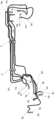
- the figure which showed the state which the pipe joint was attached and a plurality of bent brake tubes were assembled.
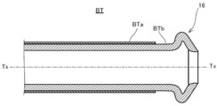
- the figure which showed the brake tube which ISO flare which is an example of an annular part was formed in the terminal.
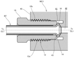
- the figure which showed the state which the brake tube was connected to the master cylinder which is an example of a mating member.
- the figure which showed the brake tube in which the double flare which is another example of an annular part was formed in a terminal.
- FIG. 6 is a cross-sectional view showing a part of a master cylinder which is an example of a mating member to which the brake tube of FIG. 7 is connected.
- FIG. 6 is an enlarged cross-sectional view of the IX portion of FIG.
- an automobile brake tube is used as a pipe for transmitting the pressure generated in the master cylinder to a brake unit provided for each wheel.
- an ABS unit or an ESC unit is provided from the master cylinder to the brake unit, and the brake tube is also used for connecting these units.
- a plurality of brake tubes having different pipe diameters are selected according to various conditions such as pressure resistance required between these units.
- a plurality of brake tube BTs are supplied to an automobile assembly line as an assembly product which is assembled by, for example, a resin clamp C and bent according to the bottom layout of the automobile.
- a double-wound tube made of a metal plate material such as a steel plate and having excellent pressure resistance is used in order to withstand the operating pressure of the brake.
- a tube having an outer diameter ⁇ in the range of 4.76 to 8.00 [mm] is selected.
- Each brake tube BT is fitted with a flare nut FN that matches its outer diameter.
- an operator collectively fastens the flare nut FN mounted on each brake tube BT to each of the above units with a common tightening torque specified in advance to collectively connect the brake tube BT.
- each brake tube BT is processed for high pressure with the flare nut FN attached.
- Terminal processing for high pressure includes terminal processing that forms an annular portion Rp such as ISO flare specified by the International Organization for Standardization (ISO) and double flare specified by the Japanese Automotive Standards Organization (JASO).
- Each brake tube BT is subjected to terminal processing for forming an annular portion Rp and bending processing for forming a bent portion Bp with the flare nut FN mounted on the outer periphery. Therefore, the flare nut FN is prevented from coming off from the brake tube BT by the annular portion Rp and the bent portion Bp provided at a position away from the annular portion Rp.
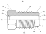
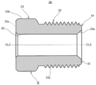
- FIG. 2 shows a flare nut 1A suitable for ISO flare.
- the flare nut 1A corresponds to an example of the pipe fitting of the present disclosure.
- the flare nut 1A is a hollow pipe joint having a through hole 10 into which a tube can be inserted.
- the flare nut 1A includes a threaded portion 12 on which a male screw 12a is formed, a head portion 13 provided on one end side of the threaded portion 12, and a contact portion 14 provided on the other end side of the threaded portion 12.
- the head 13, the screw portion 12, and the contact portion 14 are penetrated by a through hole 10 extending in the center line CL1 direction.
- the through hole 10 of the flare nut 1A shown in the figure has a shape having a constant inner diameter in the axial direction, but for example, instead of the through hole 10, the through hole has a stepped hole shape in which the inner diameter changes at a predetermined position in the axial direction. it can.
- the male screw 12a formed on the thread portion 12 is, for example, an ISO standardized metric coarse thread and meshes with the female thread 12b (see FIG. 4) formed on the mating member.
- the male screw 12a may be changed to a metric fine screw of the same standard as an example. Since the fine screw has a smaller lead angle than the coarse screw, it is possible to provide a flare nut that is more difficult to loosen with the same axial force by changing to the fine screw.
- the size of the screw portion 12 of the flare nut 1A applied to the brake tube BT described above the larger the outer diameter of the tube to be mounted, the larger the size of the screw tends to be adopted.
- the size of the threaded portion 12 is generally in the range of the nominal diameter of M10 to M14, that is, the outer diameter of 10.0 to 14.0 [mm].
- a screw having a nominal diameter in the range of 3/8 inch to 1/2 inch (about 9.53 to 12.7 [mm]) is adopted. Therefore, the male screw 12a that can be used for the flare nut 1A has an outer diameter in the range of 9.53 to 14.0 [mm].
- the head 13 is a portion where tightening torque is input at the time of fastening, and has a hexagonal shape standardized so that it can be fastened with a general tool such as a flare nut wrench.
- the head 13 includes a hollow circular flat surface 13a oriented in the axial direction and six side surfaces 13b with which the tools mesh.
- the flat surface 13a corresponds to an example of the first plane, and any one of the six side surfaces 13b corresponds to an example of the second plane.
- the size of the head 13 is selected according to the size of the screw portion 12, but unlike the case of the standardized bolt head, the size is standardized to some extent in order to reduce the number of tool changes.
- the contact portion 14 is provided at the right end of FIG. 2 along the center line CL1, in other words, at the end of the male screw 12a on the traveling direction side at the time of fastening.
- the contact portion 14 has a function of pressing the annular portion 16 against the mating member while contacting the annular portion 16 (see FIG. 3) formed as an ISO flare at the time of fastening to the mating member.
- the contact portion 14 includes a contact surface 14a that contacts the annular portion 16 and a cylindrical portion 14b that extends from the threaded portion 12 to the end side.
- a chamfered portion 10a inclined at about 45 ° with respect to the center line CL1 direction is provided at the boundary portion between the contact portion 14 and the through hole 10.
- the chamfered portion 10a alleviates the interference between the tube exterior and the flare nut 1A at the time of fastening and the stress concentration at the boundary portion between the through hole 10 and the contact portion 14.
- the chamfered portion 10a has a conical surface that appears in the cross section with respect to the center line CL1 and has a straight ridge line.
- a processed portion having a curved surface whose ridgeline is a curve drawn by one or a plurality of arcs that are convex toward the center may be provided.
- the inner diameter of the contact portion 14 is determined by the inner diameter of the through hole 10.
- the inner diameter d of the contact portion 14 is, for example, 4.98 [mm] when the outer diameter ⁇ of the brake tube BT is 4.76 [mm], and 6. when the outer diameter ⁇ is 6.0 [mm]. Set to 24 [mm], 6.59 [mm] when the outer diameter ⁇ is 6.35 [mm], and 8.29 [mm] when the outer diameter ⁇ is 8.0 [mm]. Will be done.
- the inner diameter d of the contact portion 14 allows an error of +0.15 [mm]. Therefore, the inner diameter d of the contact portion 14 that can be adopted for the flare nut 1A is in the range of 4.98 to 8.44 [mm].
- the annular portion 16 is formed at the end of the brake tube BT.
- An example of the formation procedure is as follows. First, the resin coating layer BTa of the brake tube BT is peeled from the terminal over a predetermined range in the tube axis Tx direction in the circumferential direction. Next, an ISO flare-shaped annular portion 16 is formed that projects outward in the pipe radial direction orthogonal to the pipe axis Tx with respect to the terminal portion of the peeled portion BTb from which the resin coating layer has been peeled off. Depending on the resin material of the resin coating layer BTa, the annular portion 16 may be formed with respect to the terminal portion of the brake tube BT without peeling off the resin coating layer BTa.
- the master cylinder MC1 which is an example of the mating member, has a housing 40.
- the housing 40 is formed with an insertion hole 41 into which the brake tube BT is inserted.
- the insertion hole 41 opens to the outside of the housing 40, and the opposite side of the opening communicates with the liquid passage 42 formed in the housing 40.
- the liquid passage 42 opens at the bottom 43 of the insertion hole 41.
- the bottom portion 43 is formed in a shape retracted toward the inside of the device so as to match the shape of the annular portion 16 of the brake tube BT.
- a female screw 12b that meshes with the male screw 12a of the flare nut 1A is formed on the inner peripheral surface of the housing 40 in which the insertion hole 41 is formed.
- the brake tube BT is inserted so that the annular portion 16 of the brake tube BT abuts on the bottom 43 of the insertion hole 41.
- the flare nut 1A is brought close to the insertion hole 16 and the male screw 12a of the screw portion 12 and the female screw 12b of the housing 40 are engaged with each other.
- the contact portion 14 comes into contact with the annular portion 16.
- the flare nut 1A is tightened while bringing the contact portion 14 into contact with the annular portion 16, the annular portion 16 is pressed against the bottom portion 43 by the contact portion 14.
- the annular portion 16 is sandwiched between the contact portion 14 and the bottom portion 43 and gradually deforms while shifting from elastic deformation to plastic deformation.
- the brake tube BT is liquid-tightly coupled to the master cylinder MC1.
- the coupling force of the brake tube BT is determined by the maximum axial force acting during such a fastening operation.
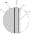
- the flare nut 1A is provided with a resin coating layer 18 in order to increase or stabilize the axial force at the time of fastening in order to firmly bond the brake tube BT.
- a zinc-based plating layer P1 is formed on the metal base M1.
- a resin coating layer 18 is provided on the plating layer P1.
- the resin coating layer 18 is located on the outermost outer surface of the plating layer P1. As long as the resin coating layer 18 is located on the outermost surface, for example, different types of resin layers may be provided between the plating layer P1 and the resin coating layer 18.
- zinc plating, zinc iron alloy plating, or zinc nickel alloy plating may be performed.
- a zinc-nickel alloy plating layer is provided as the plating layer P1.
- the plating layer P1 is provided on the entire surface of the metal base M1.
- the plating layer P1 covers the surfaces of the threaded portion 12, the head portion 13, and the contact portion 14, and the inner peripheral surface of the through hole 10 penetrating them.
- the plating layer P1 may be subjected to chemical conversion treatment.
- the plating layer P1 in this case includes a chemical conversion treatment layer on the outside thereof.
- the chemical conversion treatment layer enhances the adhesion between the plating layer P1 and the resin coating layer 18.
- the chemical conversion layer may contain metal atoms selected from titanium, zirconium, molybdenum, tungsten, vanadium, manganese, nickel, cobalt, chromium, and lead. In addition, some of these metal atoms may be contained in the chemical conversion treatment layer as compounds such as oxides.
- the chemical conversion treatment layer may be a chromium-free chemical conversion treatment layer.
- the chemical conversion treatment step for forming the chemical conversion treatment layer may be a reaction type or a coating type, and may be a trivalent chromium chemical conversion treatment or a chromium-free chemical conversion treatment.
- the plating layer P1 is formed by electrolytic plating.
- the untreated nut with the exposed metal base M1 is immersed in a plating bath containing zinc and nickel metal ions.
- the thickness of the coating deposited on the metal base M1 of the untreated nut is controlled by adjusting at least one of the current density and the processing time defined as the current per unit area during the plating process.
- the thickness of the film formed on the product to be plated is not uniform because the current density changes according to the shape of the product to be plated.
- the product to be plated includes not only parts with little shape change such as flat surface and cylindrical surface but also parts with large shape change such as convex corners and cusps on the surface side, the thickness of the coating at each part. Is different.
- the thickness of the plating layer P1 is different when the peak and the valley bottom of the thread of the threaded portion 12 are compared or when the peak and the contact surface 14a of the contact portion 14 are compared.
- the thickness of the plating layer P1 is compared between the peak of the thread of the threaded portion 12 and the contact surface 14a of the contact portion 14, the thickness of the peak tends to be smaller than that of the contact surface 14a. there were.
- the mechanical properties of the flare nut 1A change when the thickness of the plating layer P1 is different.
- the thickness of the plating layer P1 differs depending on the portion of the flare nut 1A, it is not possible to accurately evaluate the correlation between the thickness of the plating layer P1 and mechanical properties such as axial force. Therefore, the thickness of the plating layer P1 is quantitatively controlled or managed by using the joint average plating thickness described later calculated by a predetermined method.
- the resin coating layer 18 is formed in at least the coating region R (see FIG. 2) including the surfaces of the screw portion 12 and the contact portion 14.
- the coating region R is set on the entire surface of the flare nut 1A. That is, the coating region R is set on each surface of the threaded portion 12, the head portion 13 and the contact portion 14 of the flare nut 1A, and the inner peripheral surface of the flare nut 1A pierced by the through hole 10.
- the resin coating layer 18 contains a polyethylene-based substance, a lubricant, and solid particles.
- the resin coating layer 18 is formed by adhering a coating agent C containing these as a component to the coating region R.
- the polyethylene-based substance for example, polyethylene or a polyethylene copolymer can be selected.
- any one of polyethylene wax, molybdenum disulfide, graphite, or boron nitride, or any combination thereof can be selected.
- the lubricant may be solid or liquid.
- the fixed particles for example, any one of silicon dioxide, silicon nitride, or titanium nitride, or any combination thereof can be selected.
- the resin coating layer 18 is formed by a dip coating method as an example.
- the resin coating layer 18 may be formed by a spray method in which the coating agent is atomized and sprayed. This spray method is suitable for partially forming the resin coating layer 18 on the flare nut 1A.
- the friction coefficient of the resin coating layer 18 is smaller than the friction coefficient of the plating layer P1.
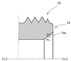
- FIG. 6 shows a flare nut 1B suitable for double flare.
- the flare nut 1B corresponds to an example of the pipe fitting of the present disclosure.
- the flare nut 1B is a hollow pipe joint having a through hole 20 into which a tube can be inserted.
- the flare nut 1B includes a threaded portion 22 on which a male screw 22a is formed, a head portion 23 provided on one end side of the threaded portion 22, and a contact portion 24 provided on the other end side of the threaded portion 22.
- the head 23, the screw portion 22, and the contact portion 24 are penetrated by a through hole 20 extending in the center line CL2 direction.
- the through hole 20 has a shape having a constant inner diameter in the axial direction, but for example, instead of the through hole 20, it can be changed to a stepped hole shape in which the inner diameter changes at a predetermined position in the axial direction. ..
- the male screw 22a formed on the screw portion 22 has the same specifications as the male screw 12a provided on the screw portion 12 of the flare nut 1A of the first form, and the male screw 22a that can be adopted as the flare nut 1B has an outer diameter thereof. It is in the range of 9.53 to 14.0 [mm]. Further, the specifications of the head 23 are the same as the specifications of the head 13 of the flare nut 1A.
- the head 23 includes a hollow circular flat surface 23a oriented in the axial direction and six side surfaces 23b with which the tool meshes.
- the flat surface 23a corresponds to an example of the first plane, and any one of the six side surfaces 23b corresponds to an example of the second plane.
- the specifications of the contact portion 24 are also the same as the specifications of the contact portion 14 of the flare nut 1A, and the contact portion 24 that can be adopted as the flare nut 1B has an inner diameter d within the range of 4.98 to 8.44 [mm]. is there.
- the contact portion 24 is provided at the right end of FIG. 6 along the center line CL2, in other words, at the end of the male screw 22a on the traveling direction side at the time of fastening.
- the contact portion 24 has a function of pressing the annular portion 26 against the mating member while contacting the annular portion 26 (see FIG. 7) formed as a double flare when the mating member is fastened.
- the contact portion 24 is provided near the end of the screw portion 22.
- There is no clear cylindrical portion such as the cylindrical portion 14b (see FIG. 2) of the flare nut 1A.
- a flare nut suitable for double flare there is also a flare nut including a cylindrical portion corresponding to the cylindrical portion 14b.
- the contact portion 24 has a conical contact surface 24a having an inclination angle of about 42 ° with respect to the axial direction.
- the annular portion 26 is formed at the end of the brake tube BT.
- An example of the formation procedure is as follows. First, the resin coating layer BTa of the brake tube BT is peeled from the terminal over a predetermined range in the tube axis Tx direction in the circumferential direction. Next, a double flare-shaped annular portion 26 is formed that projects outward in the pipe radial direction orthogonal to the pipe axis Tx with respect to the terminal portion of the peeled portion BTb from which the resin coating layer BTa has been peeled off. Depending on the resin material of the resin coating layer BTa, the annular portion 26 may be formed with respect to the terminal portion of the brake tube BT without peeling off the resin coating layer BTa.
- An insertion hole 51 having the structure shown in FIG. 8 is formed in the mating member to which the brake tube BT on which the annular portion 26 is formed is connected.
- the insertion hole 51 is formed in the master cylinder MC2, which is an example of the mating member.
- the insertion hole 51 opens to the outside of the housing 50, and the opposite side of the opening communicates with the liquid passage 52 formed in the housing 50.
- the liquid passage 52 opens to the bottom 53 of the insertion hole 51.
- the bottom portion 53 is formed in a shape protruding to the outside of the device so as to match the shape of the annular portion 26 of the brake tube BT.
- a female screw 22b that meshes with the male screw 22a of the flare nut 1B is formed on the inner peripheral surface of the housing 50 in which the insertion hole 51 is formed.
- the connection of the brake tube BT using the flare nut 1B is the same as that of the flare nut 1A, and thus the description thereof will be omitted.
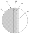
- the flare nut 1B is provided with a resin coating layer 28.
- a zinc-based plating layer P2 is formed on the metal base M2.
- a resin coating layer 28 is provided on the plating layer P2.
- the resin coating layer 28 is located on the outermost outer surface of the plating layer P2. As long as the resin coating layer 28 is located on the outermost surface, for example, different types of resin layers may be provided between the plating layer P2 and the resin coating layer 28.
- zinc plating, zinc iron alloy plating, or zinc nickel alloy plating may be performed. In this form, a zinc-nickel alloy plating layer is provided as the plating layer P2.
- the plating layer P2 is provided on the entire surface of the metal base M1.
- the plating layer P2 covers the surfaces of the threaded portion 22, the head portion 23, and the contact portion 24, and the inner peripheral surface of the through hole 20 penetrating them.
- the plating layer P2 may include a chemical conversion treatment layer on the outside. Similar to the first embodiment, for example, the plating layer P2 is formed by electrolytic plating, and the resin coating layer 28 is formed by a dip coating method. The friction coefficient of the resin coating layer 28 is smaller than the friction coefficient of the plating layer P2.
- the axial force at the time of fastening tended to decrease as the number of repetitions increased. Then, by the fastening test described below, it was found that the thickness of the zinc-based plating layer is a factor that affects the rate of decrease in axial force. Since no significant difference was found between the flare nut 1A and the flare nut 1B with respect to the test result of the fastening test, the test results of the flare nut 1A will be disclosed below.
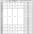
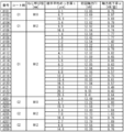
- Test sample (1) Preparation of test sample As shown in FIG. 10, a plurality of samples having different joint average plating thickness t [ ⁇ m], which will be described later, were prepared for three types of flare nuts having different shapes and sizes. .. A zinc-nickel alloy plating layer was adopted as an example of the plating layer of each sample. Further, the joint average plating thickness t was made different from each other by adjusting at least one of the current density and the processing time during the plating treatment of each sample. That is, the parameters that control the joint average plating thickness t are the current density and the processing time.
- the resin coating layer of each sample contains the above-mentioned polyethylene-based substance, lubricant, and solid particles, and one of two types of coating agents C1 and C2 having different viscosities at 25 [° C.] adheres to the coating region. It is formed by doing.
- a dip coating method was adopted as a method for forming the resin coating layer.
- the thickness was controlled by using the unit area mass w [g / m 2 ] described later, which correlates with the thickness.
- the unit area mass w of each sample is adjusted within the range of 0.79 ⁇ w ⁇ 10.07.
- the thickness of the plating layer Due to the characteristics of electrolytic plating, the thickness of the plating layer is not uniform depending on the flare nut part. It is known that the thickness of the plating layer affects the mechanical properties of flare nuts such as axial force. Therefore, the thickness of the plating layer is quantitatively controlled or controlled by using the joint average plating thickness t [ ⁇ m]. The average plating thickness t of the joint is calculated as follows.
- FIG. 11A shows a cross section of the flare nut 1A that passes through the center line CL1 and is orthogonal to any two of the six side surfaces 13b of the head 13.
- the average plating thickness t of the joint is calculated by measuring the thickness of the plating layer at each part appearing in this cross section.
- Second region Ar 2 The second region Ar 2 is a region set on the side surface 13b of the head 13. As shown in FIG.
- the second region Ar 2 when the distance to the end of the side surface 13b from the flat surface 13a and the L 2, with a focus on a position apart L 2/2 from the flat surface 13a radius It is set within a circle of 100 [ ⁇ m].
- B3 Third region Ar 3
- the third region Ar 3 is set within a circle having a radius of 100 [ ⁇ m] centered on the midpoint of the trailing flank of the third thread R 3 .
- Fourth region Ar 4 The fourth region Ar 4 is set within a circle having a radius of 100 [ ⁇ m] centered on the midpoint of the trailing flank of the fourth screw thread R 4 .
- (B5) Fifth region Ar 5 The fifth region Ar 5 is a region set on the contact surface 14a of the contact portion 14. As shown in FIG.
- the fifth region Ar 5 the distance from the center line CL1 to the inner peripheral surface of the through hole 10 (inner diameter of the contact portion 14) and r 51, the outer peripheral surface of the contact portion 14 from the center line CL1
- the first region Ar 1 to the fourth region Ar 4 are the same as the flare nut 1A, but the fifth region Ar 5 is set as shown in FIG. 11B.
- FIG. 11B the first region Ar 1 to the fourth region Ar 4 are the same as the flare nut 1A, but the fifth region Ar 5 is set as shown in FIG. 11B.
- 11B shows a part of a cross section of the flare nut 1B that passes through the center line CL2 and is orthogonal to any two of the six side surfaces 23b of the head 23.
- the fifth region Ar 5 is set within a circle having a radius of 100 [ ⁇ m] centered on the midpoint of the contact surface 24a of the contact portion 24 appearing in this cross section.
- each region Ar i which is set, as shown in FIG. 11C, measure the thickness of the plating layer at 107 points arranged in one direction in [[mu] m] interval p 1 ⁇ p 7 Then, the arithmetic mean of these seven measured values is calculated for each region A r i . As a result, five calculated values X 1 , X 2 , X 3 , X 4 , and X 5 corresponding to the five regions Ar i are acquired.
- the actual flare nut 1A or flare nut 1B is cut in the vertical direction with a cutting machine.
- the cutting position by the cutting blade is slightly offset in the radial direction from the center line so as not to be excessively polished beyond the center line of the actual product in the polishing step described later.
- the polishing allowance is secured and a measurement piece slightly larger than half can be obtained.
- the measuring piece is molded with resin so as to cover it. The orientation of the cut surface of the measurement piece should be known even after molding.
- the resin-molded measurement piece is surface-polished with a grinding machine until the cross section including the center line shown in FIG. 11A or FIG. 11B appears.
- each part of the polished cross section was imaged at a magnification of 1000 to 2500 times using the following digital microscope as an example, and the thickness of the plating layer was measured based on the captured image.
- the thickness of the resin coating layer correlates with the mass of the substance adhering to the coating region. Therefore, as a physical quantity that correlates with the thickness of the resin coating layer, a value obtained by dividing the mass difference between the presence and absence of the resin coating layer by the surface area of the coating region is defined as the unit area mass w [g / m 2 ]. The thickness of the resin coating layer was quantified using this unit area mass w.
- the unit area mass w was calculated by dividing the mass difference between the mass of the flare nut before the resin coating treatment and the mass of the flare nut after the formation of the resin coating layer by the total surface area of the flare nut. Contrary to this method, the unit area mass w is the mass difference between the mass of the flare nut on which the resin coating layer is formed and the mass of the flare nut after removing the resin coating layer, and is the total surface area of the flare nut. It may be calculated by dividing by. As a method for removing the resin coating layer, for example, after immersing the flare nut on which the resin coating layer is formed in a high-temperature organic solvent, the flare nut after immersion is washed with an organic solvent separately prepared for cleaning and dried. There is a way.
- an organic solvent capable of dissolving polyethylene such as benzene and decalin can be used as the organic solvent for immersing the flare nut.
- the soaking time and drying time are set to such an extent that they can be identified with flare nuts before the resin coating treatment.
- the immersion time in the organic solvent may be 5 hours, and the drying time may be 1 hour after cleaning with the organic solvent for cleaning.
- the flare nut from which the resin coating layer has been removed by this treatment can be equated with the flare nut before the resin coating treatment.
- the total surface area of the flare nut was calculated using the surface area calculation function attached to the CAD software based on the flare nut design drawing data. By using this function, the surface area can be calculated for any range of flare nuts. Although there may be a slight difference in the calculated surface area depending on the CAD software, the difference can be ignored in the calculation of the unit area mass w calculated with two digits after the decimal point. Further, the error between the calculated value by the CAD software and the calculated value calculated based on the measurement data obtained by three-dimensionally measuring the external dimensions of the actual product is also negligible.
- each sample was given sample numbers # 101 to # 209 to distinguish them from each other.
- the first digit of the sample number is given according to the types of coating agents C1 and C2.
- FIG. 12 schematically shows the configuration of the axial force measuring device 100.
- a test tube T corresponding to the brake tube BT is set in the axial force measuring device 100.
- the test tube T is set in the axial force measuring device 100 so that the tube axis Tx and the reference axis SAx coincide with each other.
- a flare nut sample S is attached to the test tube T, and a test annular portion TR is formed at the end of the test tube T.
- the axial force measuring device 100 performs a tightening operation on the sample S until a predetermined tightening torque is reached, and connects the test tube T to the test member TM corresponding to the mating member.
- the axial force measuring device 100 measures the axial force of the sample S and other physical quantities in the process of the tightening operation.
- the axial force measuring device 100 includes a frame 101, and the frame 101 is installed on the floor of a test room or the like as an example.
- the frame 101 of the axial force measuring device 100 includes a tightening operation unit 102 that performs a tightening operation on the sample S, a mating member holding unit 103 that holds the test member TM, and a tube holding unit that holds the test tube T. 104 and 104 are provided respectively.
- the tightening operation unit 102, the mating member holding unit 103, and the tube holding unit 104 are provided on the frame 101 so as to be aligned in the reference axis SAx direction.
- the tightening operation unit 102 includes a tool 110 fitted to the head of the sample S, a motor 111 that rotationally drives the tool 110 around the reference axis SAx, and a tightening torque that outputs a signal corresponding to the drive resistance of the tool 110. Includes sensor 112.
- the mating member holding portion 103 holds the test member TM by the first jig 103a and the second jig 103b divided in the reference axis SAx direction.
- the test member TM is divided in the reference axis SAx direction, and one first part TMa is held by the first jig 103a and the other second part TMb is held by the second jig 103b.
- the first part TMa has a screw hole 115 in which a female screw 115b that meshes with the male screw of sample S is formed.
- the second part TMb has a bottom 116 to which the test annular portion TR of the test tube T is pressed.
- the hole shape corresponds to the above-mentioned insertion holes 41 and 51.
- the first jig 103a and the second jig 103b can be held in a state in which the screw hole 115 of the first part TMa and the bottom 116 of the second part TMb are concentrically abutted against each other.
- the first jig 103a is fixed to the frame 101.
- the second jig 103b is constrained in the reference axis SAx direction with the first part TMa and the second part TMb abutting against each other and the load cell 117 intervening.
- the tube holding portion 104 includes a fixing mechanism 118 that clamps a fixed position set at a predetermined distance (for example, 0.3 [m]) from the terminal of the test tube T, and a torque around the reference axis SAx generated in the fixing mechanism 118. It is equipped with a rotating torque sensor 119 that outputs a signal according to the above.
- the sample S advances while meshing with the female screw 115b formed on the first part TMa of the test member TM, and the test annular portion TR moves to the second part TMb. It is pressed against the bottom 116 formed on the.
- a force that separates the first part TMa and the second part TMb from each other in the reference axis SAx direction acts on them.
- the first part TMa is held by the first jig 103a fixed to the frame 101 so that it cannot move in the reference axis SAx direction, while the second part TMb is held by the second jig 103b to be a load cell.
- the control device 120 may be a personal computer as an example.
- the control device 120 executes a predetermined process for the input signal from each sensor, and stores as a measurement result data in which the axial force and the accompanying torque are associated with the tightening torque input to the sample S. And, if necessary, the measurement result can be output to an output means such as a display.
- the above operation was set as the first fastening test, and the fastening test including the tightening operation, the measurement of the axial force, and the releasing operation was repeated a total of 5 times without exchanging the test tube T and the sample S.
- the axial force and the accompanying torque were acquired and recorded as measured values by the axial force measuring device 100.
- the interval between each fastening test was set to 60 [sec] as an example.
- the number of repetitions of the fastening test was determined based on the limit of the number of times the brake tube of the car can be removed within the period from the time of new car to the time of scrapping.
- the brake tube of an automobile is not often removed, its limit is estimated based on a discrete probability distribution using the number of removals as a random variable.
- three elements, an ABS unit, a master cylinder, and a brake unit are assumed as mating members to which the brake tube is connected, and it is a prerequisite that the flare nut is always reused when these three elements fail, and the three elements fail.
- the probability that the number of times the brake tube was removed was 6 times or exceeded 6 times was negligibly low. Therefore, the number of repetitions of the fastening test was set to 5 times, which is less than 6 times.
- F 1 [kN] is the initial axial force which is the maximum axial force generated in the first fastening test.
- F n [kN] is the nth axial force, which is the maximum axial force generated in the nth (however, 1 ⁇ n ⁇ 6) fastening test.
- Equation 2 is conditioned on the condition that 0 ⁇ F n ⁇ F n-1 is established when the n- 1th axial force generated in the n-1th time is F n-1 . Therefore, ⁇ > 0.
- Criteria a define the scope of the initial axial force F 1.
- the upper limit of the reference a was determined based on the upper limit of the accompanying torque.
- the upper limit of the accompanying torque is determined in consideration of the strength of the tube and the vibration of the vehicle, and is 1.0 [Nm] as an example.
- the accompanying torque and the axial force are correlated, and the axial force corresponding to the upper limit of the accompanying torque is uniquely determined.
- the axial force is 14.0 [kN] as an example.
- the accompanying torque was maximum at the time of initial fastening accompanied by plastic deformation of the annular portion formed in the tube, and tended to decrease from the time of reuse of the flare nut and not change so much depending on the number of times of reuse.
- the lower limit of the reference a is set so that the coupling force required for the tube can be secured even if the axial force decreases when the flare nut is reused.
- the axial force is 10.0 [kN] as an example. Therefore, when the axial force exceeds the lower limit of the reference a, the coupling force required for the tube can be secured even at the time of reuse.
- Criteria b defines the upper limit of the axial force reduction rate ⁇ .
- the axial force reduction rate ⁇ becomes 1.75 [kN / time] or more as an example, it may fall below the lower limit of the axial force even if the flare nut is fastened with the same tightening torque as when it was first tightened during reuse.
- the lower limit of this axial force is set based on the lower limit of the coupling force required for the brake tube.
- the suitability of the standard a and the standard b depends on the average plating thickness t of the joint regardless of the difference in the coating agent. Accordance joint average plating thickness t increases, generally the first axial force F 1 and the axial force reduction rate ⁇ tends to decrease. Conversely, according to the joint average plating thickness t is small, generally the first axial force F 1 and the axial force reduction rate ⁇ tends to increase. It was found that if the joint average plating thickness t is too large, the standard a is non-conforming, and if the joint average plating thickness t is too small, the standard b is non-conforming.
- the average plating thickness t of the pass sample is in the range of 2.1 ⁇ t ⁇ 19.7.
- the upper limit of the joint average plating thickness t is preferably less than 16.0 [ ⁇ m], for example, 14.0. Less than [ ⁇ m] is more preferable, and less than 12.0 [ ⁇ m] is even more preferable. That is, the average plating thickness t of the joint is preferably 2.1 ⁇ t ⁇ 16.0, more preferably 2.1 ⁇ t ⁇ 14.0, and even more preferably 2.1 ⁇ t ⁇ 12.0.
- the present disclosure is not limited to each of the above forms and can be carried out in various forms.
- the flare nut is used for the metal brake tube, but the target of the flare nut is not limited to the brake tube.
- various metal tubes such as vapor tubes can be used.
- Each of the flare nuts 1A and 1B is only an example of a pipe fitting used to connect a metal tube.
- the present disclosure differs from the illustrated shape as long as the male screw has an outer diameter of 9.53 to 14.0 [mm] and the contact portion has an inner diameter of 4.98 to 8.44 [mm]. It can also be applied to flare nuts.
- the average plating thickness t of the joint may be within the above range. Therefore, the type of zinc-based plating may be selected according to the corrosion resistance performance required according to the application of the flare nut.
- the coating region R according to each of the above forms is set on the entire surface of the flare nut, that is, the entire surface of the threaded portion, the head portion, and the contact portion, and the inner peripheral surface of the flare nut pierced by the through hole. ..
- setting the coating region on the entire surface is only an example.
- the coating region may be set only on the surface of the threaded portion and the surface of the contact portion. In this case, the inner peripheral surface and the surface of the head of the flare nut pierced by the through hole are excluded from the coating region.
- the coating region is not limited to be set on the entire surface of each of the threaded portion and the contact portion.
- a coating region may be set on a part of each surface of the threaded portion and the contact portion.
- a coating region may be set on a portion of the surface of the threaded portion of preferably 40% or more, more preferably 60% or more, and further preferably 80% or more.
- a coating region may be set on a portion of the surface of the contact portion, preferably 40% or more, more preferably 60% or more, and further preferably 80% or more.
- the surface of the threaded portion means the surface of the thread forming range that actually meshes with the female thread or is scheduled to mesh with the female thread.
- the surface of the contact portion means a contact surface that actually comes into contact with the annular portion or is scheduled to come into contact with the annular portion.
- the pipe joint of the present disclosure is in a state in which an annular portion (Rp, 16, 26) projecting outward in the pipe radial direction is attached to the outer periphery of a metal tube (BT) provided at the end and is in contact with the annular portion.
- a pipe joint (1A, 1B) capable of connecting the tube to the mating member by being fastened to the mating member (MC1, MC2), and to a female screw (12b, 22b) provided on the mating member.
- a contact portion (14, 24) provided on the other end side of the threaded portion for pressing the annular portion against the mating member while contacting the annular portion at the time of fastening to the mating member, and the threaded portion and the head.
- a resin coating located on the outermost surface of the zinc-based plating layer (P1, P2) provided on the portion and the contact portion and outside the zinc-based plating layer and containing a polyethylene-based substance, a lubricant, and solid particles.
- Through holes (10, 20) comprising layers (18, 28), each of the threaded portion, the head portion, and the contact portion extending in a direction parallel to the traveling direction of the male screw at the time of fastening.
- the male thread of the threaded portion has an outer diameter of 9.53 to 14.0 [mm], and the head portion is a first plane (directed in a direction opposite to the traveling direction). 13a, 23a) and a second plane (13b, 23b) orthogonal to the first plane, the contact portion includes a contact surface (14a, 24a) accessible to the annular portion, and 4.98.
- the first thread is set as the first thread (R 1 ) and the second thread is used. Is defined as the second thread (R 2 ), the third thread is defined as the third thread (R 3 ), and the fourth thread is defined as the fourth thread (R 4 ).
- the zinc-based plating that defines a defined fifth region (Ar 5 ) and measures at seven points arranged in one direction at intervals of 10 [ ⁇ m] in each region of the first region to the fifth region.
- the five calculated values obtained by calculating the arithmetic average of the layer thickness for each of the first region to the fifth region are X 1 , X 2 , X 3 , X 4 , and X 5, and the second screw thread in the cross section.
- a test tube having a test member (TM) corresponding to the mating member and a test annular portion (TR) having the same outer diameter as the tube and corresponding to the annular portion (TR).
- T is prepared and fastened to the test member with a predetermined tightening torque in contact with the test annular portion, and after the fastening operation, the fastening is loosened to join the test tube.
- the fastening test including the releasing operation is repeated n times (however, 1 ⁇ n ⁇ 6), the maximum axial force generated in the first fastening test is set to the initial axial force F 1 [kN], and the first axial force is the first.
- the maximum axial force generated in the nth fastening test is defined as the nth axial force F n [kN], and the value obtained by ⁇ (F n ⁇ F 1 ) / (n-1) is the axial force reduction rate ⁇ [kN / When defined as [times], 0 ⁇ ⁇ 1.75 may be established. According to this aspect, since 0 ⁇ ⁇ 1.75 is established for the axial force decrease rate ⁇ , the decrease in the axial force at the time of reuse can be suppressed, and the fastening is performed with the same tightening torque as at the time of the first use. However, the desired binding force can be obtained when reused.
- the tube is a brake tube used for a brake pipe of an automobile, and when the tightening torque is in the range of 12.0 to 22.0 [Nm], 10.0 ⁇ F 1 ⁇ . 14.0 may hold. In this case, since it is guaranteed that the upper limit value of the rotating torque is not exceeded, it is possible to prevent the pipe joint from being loosened while avoiding damage to the brake tube.
- the tube with a pipe joint of the present disclosure is provided with an annular portion (Rp, 16, 26) protruding outward in the pipe radial direction at an end portion, and a bent portion (Bp) is provided at a position away from the annular portion.
- the metal tube (BT) is attached to the outer periphery of the tube in a state of being prevented from coming off by the annular portion and the bent portion, and is fastened to a mating member in a state of being in contact with the annular portion.
- each of the screw portion, the head portion, and the contact portion has through holes (10, 20) extending in a direction parallel to the traveling direction of the male screw at the time of fastening.
- the male thread of the threaded portion is pierced and has an outer diameter of 9.53 to 14.0 [mm]
- the head is a first plane (13a, which is directed in a direction opposite to the traveling direction. 23a) and second planes (13b, 23b) orthogonal to the first plane
- the contact portion includes contact surfaces (14a, 24a) accessible to the annular portion, and 4.98-8.
- the first thread is the first thread (R 1 ) and the second thread is the second thread.
- the third thread is defined as the third thread (R 3 )
- the fourth thread is defined as the fourth thread (R 4 ).
- the fourth region (Ar 4 ) set to the chasing flank of the fourth screw thread, and the contact surface of the contact portion.
- the zinc-based plating that defines a set fifth region (Ar 5 ) and measures at seven points arranged in one direction at intervals of 10 [ ⁇ m] in each region of the first region to the fifth region.
- the five calculated values obtained by calculating the arithmetic average of the layer thickness for each of the first region to the fifth region are set to X 1 , X 2 , X 3 , X 4 , and X 5, and the second thread is formed in the cross section.
- the four measured values obtained by measuring the thickness of the zinc-based plating layer at each of the peaks (M4) of the fourth thread are T 1 , T 2 , T 3 , and T 4 , (X 1 + X 2).
- the value obtained by + X 3 + X 4 + X 5 + T 1 + T 2 + T 3 + T 4 ) / 9 is defined as the joint average plating thickness t [ ⁇ m], 2.1 ⁇ t ⁇ 19.7 holds. is there.
- this tube with a pipe joint it is possible to provide a tube having a pipe joint that can secure the mechanical characteristics required at the time of reuse.
- a test tube having a test member (TM) corresponding to the mating member and a test annular portion (TR) having the same outer diameter as the tube and corresponding to the annular portion (TR).
- T is prepared and fastened to the test member with a predetermined tightening torque in contact with the test annular portion, and after the fastening operation, the fastening is loosened to join the test tube.
- the fastening test including the releasing operation is repeated n times (however, 1 ⁇ n ⁇ 6), the maximum axial force generated in the first fastening test is set to the initial axial force F 1 [kN], and the first axial force is the first.
- the maximum axial force generated in the nth fastening test is defined as the nth axial force F n [kN], and the value obtained by ⁇ (F n ⁇ F 1 ) / (n-1) is the axial force reduction rate ⁇ [kN / When defined as [times], 0 ⁇ ⁇ 1.75 may be established. According to this aspect, since 0 ⁇ ⁇ 1.75 is established for the axial force decrease rate ⁇ , the decrease in the axial force at the time of reuse can be suppressed, and the fastening is performed with the same tightening torque as at the time of the first use. However, the desired binding force can be obtained when reused.
- the tube is a brake tube used for a brake pipe of an automobile, and when the tightening torque is in the range of 12.0 to 22.0 [Nm], 10.0 ⁇ F 1 ⁇ . 14.0 may hold.
- 10.0 ⁇ F 1 ⁇ 14.0 is established for the initial axial force F 1 , it is guaranteed that the upper limit of the accompanying torque is not exceeded, and the tube used for the brake piping is damaged. It is possible to prevent the pipe joint from being loosened while avoiding this.
- annular portion projecting outward in the pipe radial direction is attached to the outer periphery of a metal tube (BT) provided with an end portion and contacts the annular portion.
- a pipe joint (1A, 1B) capable of connecting the tube to the mating member by being fastened to the mating member (MC1, MC2) in this state, and a female screw (12b, 22b) provided on the mating member.
- a threaded portion (12, 22) formed with a male screw (12a, 22a) that meshes with the threaded portion, and a head portion (13, 23) provided on one end side of the threaded portion and to which a tightening torque is input at the time of fastening.
- a contact portion (14, 24) provided on the other end side of the threaded portion for pressing the annular portion against the mating member while contacting the annular portion at the time of fastening to the mating member, and the threaded portion.
- a zinc-based plating layer (P1, P2) provided on the head and the contact portion, and an outermost surface outside the zinc-based plating layer, which contains a polyethylene-based substance, a lubricant, and solid particles.
- the first male thread of the threaded portion, which is pierced in 20) has an outer diameter of 9.53 to 14.0 [mm], and the head is directed in a direction opposite to the traveling direction.
- a plane (13a, 23a) and a second plane (13b, 23b) orthogonal to the first plane are included, and the contact portion includes a contact surface (14a, 24a) that can contact the annular portion, and 4 A cross section having an inner diameter of .98 to 8.44 [mm], including a center line (CL1, CL2) extending in the same direction as the through hole, and orthogonal to the second plane of the head (FIG. 11A or In the cross section of FIG. 11B), when the number of threads (R i ) constituting the male screw is counted from the head side, the first thread is set as the first thread (R 1 ) and the second thread is used.
- the thread is defined as the second thread (R 2 ), the third thread is defined as the third thread (R 3 ), and the fourth thread is defined as the fourth thread (R 4 ).
- the first region (Ar 1 ) set on the first plane of the head
- the second region (Ar 2 ) set on the second plane of the head
- the follow-up of the third thread A third region (Ar 3 ) set on the side flank
- the zinc system was measured at seven points arranged in one direction at intervals of 10 [ ⁇ m] in each region of the first region to the fifth region, defining a fifth region (Ar 5 ) set in.
- the five calculated values calculated by calculating the arithmetic average of the thickness of the plating layer for each of the first to fifth regions are set to X 1 , X 2 , X 3 , X 4 , and X 5, and the second screw in the cross section.
- the value obtained by + X 2 + X 3 + X 4 + X 5 + T 1 + T 2 + T 3 + T 4 ) / 9 is defined as the joint average plating thickness t [ ⁇ m], and the test member (TM) corresponding to the mating member.
- a test tube (T) having the same outer diameter as the tube and having a test annular portion (TR) corresponding to the annular portion, and 12.0 to 22 in contact with the test annular portion.
- a fastening test including a fastening operation of fastening to the test member with a tightening torque within the range of .0 [Nm] and a releasing operation of loosening the fastening after the fastening operation to release the coupling of the test tube.
- the maximum axial force generated in the first fastening test is set to the initial axial force F 1 [kN], and the maximum axis generated in the nth fastening test.
- the force is defined as the nth axial force F n [kN] and the value obtained by ⁇ (F n ⁇ F 1 ) / (n-1) is defined as the axial force reduction rate ⁇ [kN / time], 10.
- the range of the joint average plating thickness t is set so that 0 ⁇ F 1 ⁇ 14.0 and 0 ⁇ ⁇ 1.75 are established.
- the range of the joint average plating thickness t may be 2.1 ⁇ t ⁇ 19.7. According to this aspect, when fastening and disengaging are repeated, it is possible to obtain an initial axial force at which the accompanying torque is less than the upper limit value, and it is possible to suppress the rate of decrease in axial force to a low level.
- an annular portion protruding outward in the pipe radial direction is attached to the outer periphery of a metal tube (BT) provided at an end thereof, and the annular portion is described.
- Measurement of the plating thickness of a pipe joint that can be bonded to the mating member and is applied to a plated pipe joint by being fastened to the mating member (MC1, MC2) in contact with the portion.
- the pipe joint has a threaded portion (12, 22) formed with a male thread (12a, 22a) that meshes with a female thread (12b, 22b) provided on the mating member, and one end side of the threaded portion.
- the head (13, 23) to which the tightening torque is input at the time of fastening and the other end side of the screw portion are provided in the above, and the annular portion is contacted with the annular portion at the time of fastening to the mating member.
- the threaded portion includes a contact portion (14, 24) for pressing the portion against the mating member, the threaded portion, the head portion, and a plating layer (P1, P2) provided on the contact portion.
- Each of the head and the contact portion is pierced by through holes (10, 20) extending in a direction parallel to the traveling direction of the male screw at the time of fastening, and the male screw of the thread portion is 9.53.
- the head has an outer diameter of about 14.0 [mm], and the head has a first plane (13a, 23a) directed in a direction opposite to the traveling direction and a second plane (13a, 23a) orthogonal to the first plane ( 13b, 23b), the contact portion includes a contact surface (14a, 24a) that can contact the annular portion, and has an inner diameter of 4.98 to 8.44 [mm].
- the first thread is the first thread (R 1 )
- the second thread is the second thread (R 2 )
- the third thread is the third thread.
- the thread is defined as the third thread (R 3 )
- the fourth thread is defined as the fourth thread (R 4 )
- the first region on the first plane of the head in the cross section is defined. (Ar 1 ), the second region (Ar 2 ) on the second plane of the head, the third region (Ar 3 ) on the trailing flank of the third thread, and the chasing of the fourth thread.
- Five calculated values calculated for each of the first to fifth regions by calculating the arithmetic average of the thickness of the plating layer measured at seven points arranged in one direction at intervals of 10 [ ⁇ m] in each of the five regions.
- the thickness of the plating layer is measured at each of the peak (M 2 ), the valley bottom (M 3 ) between the third thread and the fourth thread, and the peak (M 4 ) of the fourth thread.
- the average plating thickness t of the joint can be obtained based on the measured value of the thickness of the plating layer at a plurality of locations of the pipe joint.
- the thickness of the plating layer is not uniform in each part of the fitting. However, its thickness affects the mechanical properties of the fitting such as axial force.
- the joint average plating thickness t as a parameter representing the thickness of the plating layer of the pipe joint, the correlation between the thickness of the plating layer and the mechanical properties is not affected by the location variation of the thickness of the plating layer. Can be evaluated accurately. For example, in the case of mass production of plated pipe joints, by controlling the thickness of the plating layer using the joint average plating thickness t, the mechanical characteristics such as axial force of each pipe joint can be accurately determined. It is possible to make an estimate.
- the zinc-based plating layers P1 or P2 of each of the above forms correspond to an example of the plating layers disclosed above.
- the above disclosure may or may not have a resin coating layer outside the plating layer. Therefore, the above disclosure can also be applied to a pipe joint in which the plating layer is located on the outermost surface.
Landscapes
- Engineering & Computer Science (AREA)
- General Engineering & Computer Science (AREA)
- Mechanical Engineering (AREA)
- Transportation (AREA)
- Non-Disconnectible Joints And Screw-Threaded Joints (AREA)
- Mutual Connection Of Rods And Tubes (AREA)
- Connection Of Plates (AREA)
Abstract
Le présent joint de tuyaux comprend : une couche de placage de zinc ; et une couche de revêtement de résine qui est située sur une surface la plus à l'extérieur qui est plus éloignée sur l'extérieur du joint de tuyaux que la couche de placage de zinc, et qui contient un matériau de polyéthylène, un lubrifiant et des particules solides. Lorsque l'épaisseur de placage moyenne de soudure t se rapportant à l'épaisseur de la couche de placage de zinc est définie, le rapport 2,1 < t < 19,7 est satisfait.
Priority Applications (3)
| Application Number | Priority Date | Filing Date | Title |
|---|---|---|---|
| CN202080056665.8A CN114207338A (zh) | 2019-08-09 | 2020-08-07 | 管接头以及带管接头的管道 |
| EP20852970.1A EP4012202A4 (fr) | 2019-08-09 | 2020-08-07 | Joint de tuyaux et tube comportant un joint de tuyaux |
| US17/634,064 US11958454B2 (en) | 2019-08-09 | 2020-08-07 | Tube fitting and tube equipped with tube fitting |
Applications Claiming Priority (2)
| Application Number | Priority Date | Filing Date | Title |
|---|---|---|---|
| JP2019-156189 | 2019-08-09 | ||
| JP2019156189A JP2021028535A (ja) | 2019-08-09 | 2019-08-09 | 管継手及び管継手付きチューブ |
Publications (1)
| Publication Number | Publication Date |
|---|---|
| WO2021029363A1 true WO2021029363A1 (fr) | 2021-02-18 |
Family
ID=74569690
Family Applications (1)
| Application Number | Title | Priority Date | Filing Date |
|---|---|---|---|
| PCT/JP2020/030385 WO2021029363A1 (fr) | 2019-08-09 | 2020-08-07 | Joint de tuyaux et tube comportant un joint de tuyaux |
Country Status (5)
| Country | Link |
|---|---|
| US (1) | US11958454B2 (fr) |
| EP (1) | EP4012202A4 (fr) |
| JP (1) | JP2021028535A (fr) |
| CN (1) | CN114207338A (fr) |
| WO (1) | WO2021029363A1 (fr) |
Citations (5)
| Publication number | Priority date | Publication date | Assignee | Title |
|---|---|---|---|---|
| JP2009299895A (ja) | 2008-06-17 | 2009-12-24 | Ti Automotive (Heidelberg) Gmbh | パイプを接続するためのねじ要素及び装置 |
| EP2706277A2 (fr) | 2012-09-10 | 2014-03-12 | Cooper-Standard Automotive (Deutschland) GmbH | Vis de tube destinée à être fixée sur une conduite et procédé de fabrication d'une telle vis de tube |
| JP2015230099A (ja) | 2014-06-06 | 2015-12-21 | テーイー・アウトモティーフェ(ハイデルベルク)ゲゼルシャフト・ミト・ベシュレンクテル・ハフツング | 配管の接続のためのネジ要素及びこのネジ要素を有する管接続装置 |
| JP6566376B1 (ja) * | 2019-02-22 | 2019-08-28 | 三桜工業株式会社 | 管継手及び管継手付きチューブ並びに管継手の製造方法 |
| JP2019156189A (ja) | 2018-03-14 | 2019-09-19 | 東日本旅客鉄道株式会社 | 電車線路用架線の可動支持装置及びこれを用いた線路切替工法 |
Family Cites Families (11)
| Publication number | Priority date | Publication date | Assignee | Title |
|---|---|---|---|---|
| JP3253945B2 (ja) * | 1999-01-25 | 2002-02-04 | 三桜工業株式会社 | 被覆鋼材 |
| WO2003102457A1 (fr) * | 2002-05-31 | 2003-12-11 | Sumitomo Metal Industries, Ltd. | Joint à vis destiné à un tuyau en acier |
| US7842403B2 (en) * | 2006-02-23 | 2010-11-30 | Atotech Deutschland Gmbh | Antifriction coatings, methods of producing such coatings and articles including such coatings |
| MY161993A (en) * | 2007-12-04 | 2017-05-31 | Sumitomo Metal Ind | Threaded joint for pipes |
| EP2360405A1 (fr) * | 2010-02-19 | 2011-08-24 | TI Automotive (Heidelberg) GmbH | Dispositif de raccordement de tuyaux |
| EP2679873B1 (fr) * | 2012-06-29 | 2017-05-31 | TI Automotive (Heidelberg) GmbH | Raccordement groupé d'une conduite de véhicule automobile et d'une pièce de raccordement |
| US10072778B2 (en) * | 2015-01-08 | 2018-09-11 | Toyota Motor Engineering & Manufacturing North America, Inc. | Tube nut assembly |
| FR3035474B1 (fr) * | 2015-04-23 | 2017-04-28 | Vallourec Oil & Gas France | Element filete tubulaire dote d'un revetement metallique anticorrosion et antigrippage |
| JPWO2018074212A1 (ja) * | 2016-10-18 | 2019-08-08 | 日本製鉄株式会社 | 管用ねじ継手及び管用ねじ継手の製造方法 |
| CN110651147B (zh) * | 2017-05-22 | 2021-06-01 | 日本制铁株式会社 | 管用螺纹接头及管用螺纹接头的制造方法 |
| CN109141325B (zh) * | 2018-09-14 | 2020-12-08 | 上海交通大学 | 金属表面涂镀层厚度的非接触式测量方法及装置 |
-
2019
- 2019-08-09 JP JP2019156189A patent/JP2021028535A/ja active Pending
-
2020
- 2020-08-07 EP EP20852970.1A patent/EP4012202A4/fr active Pending
- 2020-08-07 WO PCT/JP2020/030385 patent/WO2021029363A1/fr unknown
- 2020-08-07 CN CN202080056665.8A patent/CN114207338A/zh active Pending
- 2020-08-07 US US17/634,064 patent/US11958454B2/en active Active
Patent Citations (5)
| Publication number | Priority date | Publication date | Assignee | Title |
|---|---|---|---|---|
| JP2009299895A (ja) | 2008-06-17 | 2009-12-24 | Ti Automotive (Heidelberg) Gmbh | パイプを接続するためのねじ要素及び装置 |
| EP2706277A2 (fr) | 2012-09-10 | 2014-03-12 | Cooper-Standard Automotive (Deutschland) GmbH | Vis de tube destinée à être fixée sur une conduite et procédé de fabrication d'une telle vis de tube |
| JP2015230099A (ja) | 2014-06-06 | 2015-12-21 | テーイー・アウトモティーフェ(ハイデルベルク)ゲゼルシャフト・ミト・ベシュレンクテル・ハフツング | 配管の接続のためのネジ要素及びこのネジ要素を有する管接続装置 |
| JP2019156189A (ja) | 2018-03-14 | 2019-09-19 | 東日本旅客鉄道株式会社 | 電車線路用架線の可動支持装置及びこれを用いた線路切替工法 |
| JP6566376B1 (ja) * | 2019-02-22 | 2019-08-28 | 三桜工業株式会社 | 管継手及び管継手付きチューブ並びに管継手の製造方法 |
Non-Patent Citations (1)
| Title |
|---|
| See also references of EP4012202A4 |
Also Published As
| Publication number | Publication date |
|---|---|
| US20220348181A1 (en) | 2022-11-03 |
| EP4012202A1 (fr) | 2022-06-15 |
| EP4012202A4 (fr) | 2024-01-17 |
| US11958454B2 (en) | 2024-04-16 |
| CN114207338A (zh) | 2022-03-18 |
| JP2021028535A (ja) | 2021-02-25 |
Similar Documents
| Publication | Publication Date | Title |
|---|---|---|
| JP6566376B1 (ja) | 管継手及び管継手付きチューブ並びに管継手の製造方法 | |
| KR101947951B1 (ko) | 관 접속용의 나사 요소와 이 나사 요소를 구비한 관 접속 장치 | |
| CN108474502B (zh) | 管用螺纹接头和管用螺纹接头的制造方法 | |
| EP3245007B1 (fr) | Procédé de projection de gaz froid pour la réparation ou dans certains cas la consolidation des métaux. | |
| CN101772592B (zh) | 金属部件的制造方法、具有由此制造的金属部件的结构部件和金属部件的修补方法 | |
| WO2021029363A1 (fr) | Joint de tuyaux et tube comportant un joint de tuyaux | |
| CN103097748A (zh) | 固定装置及相应的制造方法 | |
| JP5837038B2 (ja) | スタッドの少なくとも1つの寸法についての適合可能な公差範囲を有するスタッドを加工物に接合するための方法及び装置 | |
| JP7127760B2 (ja) | 管継手の軸力測定装置及び軸力測定方法 | |
| JP2022075788A (ja) | 管継手及び管継手付きチューブ | |
| WO2009016453A2 (fr) | Tige de forage à raccords de tige | |
| JP2020133895A (ja) | 管継手及び管継手付きチューブ並びに管継手の製造方法 | |
| RU68090U1 (ru) | Бурильная труба с соединительными замками | |
| EP1095989A2 (fr) | Feuille métallique revêtue de résine pour éléments de machines électroniques et outils et son procédé de fabrication | |
| KR101637500B1 (ko) | 볼 스터드의 방청피막 도금 방법 | |
| US20070243044A1 (en) | Wear resistant nut | |
| JP2018091355A (ja) | 締結構造及び締結面の製造方法 | |
| Hua et al. | Degradation of W-DLC Coatings in rolling/sliding applications | |
| US11878343B2 (en) | Housing and method of preparing same using a hybrid casting-additive manufacturing process | |
| Ciecińska et al. | Analysis of the Effect of Surface Preparation of Aluminum Alloy Sheets on the Load-Bearing Capacity and Failure Energy of an Epoxy-Bonded Adhesive Joint | |
| GB2566153A (en) | Component for a motor vehicle, and method for producing a coated component from a magnesium material | |
| WO2002090816A1 (fr) | Tube revetu multicouche et procede de fabrication associe | |
| JPS5937697B2 (ja) | 管或いは管継手用ねじの成形方法 | |
| JP2015004370A (ja) | 被膜付締結部品およびその製造方法 |
Legal Events
| Date | Code | Title | Description |
|---|---|---|---|
| 121 | Ep: the epo has been informed by wipo that ep was designated in this application |
Ref document number: 20852970 Country of ref document: EP Kind code of ref document: A1 |
|
| NENP | Non-entry into the national phase |
Ref country code: DE |
|
| ENP | Entry into the national phase |
Ref document number: 2020852970 Country of ref document: EP Effective date: 20220309 |