WO2021025132A1 - 駆動装置及び医療用ポンプ - Google Patents
駆動装置及び医療用ポンプ Download PDFInfo
- Publication number
- WO2021025132A1 WO2021025132A1 PCT/JP2020/030255 JP2020030255W WO2021025132A1 WO 2021025132 A1 WO2021025132 A1 WO 2021025132A1 JP 2020030255 W JP2020030255 W JP 2020030255W WO 2021025132 A1 WO2021025132 A1 WO 2021025132A1
- Authority
- WO
- WIPO (PCT)
- Prior art keywords
- screwed
- central axis
- drive device
- nut
- feed screw
- Prior art date
- Legal status (The legal status is an assumption and is not a legal conclusion. Google has not performed a legal analysis and makes no representation as to the accuracy of the status listed.)
- Ceased
Links
Images




Classifications
-
- F—MECHANICAL ENGINEERING; LIGHTING; HEATING; WEAPONS; BLASTING
- F16—ENGINEERING ELEMENTS AND UNITS; GENERAL MEASURES FOR PRODUCING AND MAINTAINING EFFECTIVE FUNCTIONING OF MACHINES OR INSTALLATIONS; THERMAL INSULATION IN GENERAL
- F16H—GEARING
- F16H25/00—Gearings comprising primarily only cams, cam-followers and screw-and-nut mechanisms
- F16H25/18—Gearings comprising primarily only cams, cam-followers and screw-and-nut mechanisms for conveying or interconverting oscillating or reciprocating motions
- F16H25/20—Screw mechanisms
-
- A—HUMAN NECESSITIES
- A61—MEDICAL OR VETERINARY SCIENCE; HYGIENE
- A61M—DEVICES FOR INTRODUCING MEDIA INTO, OR ONTO, THE BODY; DEVICES FOR TRANSDUCING BODY MEDIA OR FOR TAKING MEDIA FROM THE BODY; DEVICES FOR PRODUCING OR ENDING SLEEP OR STUPOR
- A61M5/00—Devices for bringing media into the body in a subcutaneous, intra-vascular or intramuscular way; Accessories therefor, e.g. filling or cleaning devices, arm-rests
- A61M5/14—Infusion devices, e.g. infusing by gravity; Blood infusion; Accessories therefor
- A61M5/142—Pressure infusion, e.g. using pumps
- A61M5/14212—Pumping with an aspiration and an expulsion action
- A61M5/14236—Screw, impeller or centrifugal type pumps
-
- A—HUMAN NECESSITIES
- A61—MEDICAL OR VETERINARY SCIENCE; HYGIENE
- A61M—DEVICES FOR INTRODUCING MEDIA INTO, OR ONTO, THE BODY; DEVICES FOR TRANSDUCING BODY MEDIA OR FOR TAKING MEDIA FROM THE BODY; DEVICES FOR PRODUCING OR ENDING SLEEP OR STUPOR
- A61M5/00—Devices for bringing media into the body in a subcutaneous, intra-vascular or intramuscular way; Accessories therefor, e.g. filling or cleaning devices, arm-rests
- A61M5/14—Infusion devices, e.g. infusing by gravity; Blood infusion; Accessories therefor
- A61M5/142—Pressure infusion, e.g. using pumps
- A61M5/145—Pressure infusion, e.g. using pumps using pressurised reservoirs, e.g. pressurised by means of pistons
-
- A—HUMAN NECESSITIES
- A61—MEDICAL OR VETERINARY SCIENCE; HYGIENE
- A61M—DEVICES FOR INTRODUCING MEDIA INTO, OR ONTO, THE BODY; DEVICES FOR TRANSDUCING BODY MEDIA OR FOR TAKING MEDIA FROM THE BODY; DEVICES FOR PRODUCING OR ENDING SLEEP OR STUPOR
- A61M5/00—Devices for bringing media into the body in a subcutaneous, intra-vascular or intramuscular way; Accessories therefor, e.g. filling or cleaning devices, arm-rests
- A61M5/14—Infusion devices, e.g. infusing by gravity; Blood infusion; Accessories therefor
- A61M5/142—Pressure infusion, e.g. using pumps
- A61M5/145—Pressure infusion, e.g. using pumps using pressurised reservoirs, e.g. pressurised by means of pistons
- A61M5/1452—Pressure infusion, e.g. using pumps using pressurised reservoirs, e.g. pressurised by means of pistons pressurised by means of pistons
- A61M5/14546—Front-loading type injectors
-
- F—MECHANICAL ENGINEERING; LIGHTING; HEATING; WEAPONS; BLASTING
- F16—ENGINEERING ELEMENTS AND UNITS; GENERAL MEASURES FOR PRODUCING AND MAINTAINING EFFECTIVE FUNCTIONING OF MACHINES OR INSTALLATIONS; THERMAL INSULATION IN GENERAL
- F16H—GEARING
- F16H25/00—Gearings comprising primarily only cams, cam-followers and screw-and-nut mechanisms
- F16H25/18—Gearings comprising primarily only cams, cam-followers and screw-and-nut mechanisms for conveying or interconverting oscillating or reciprocating motions
- F16H25/20—Screw mechanisms
- F16H25/2025—Screw mechanisms with means to disengage the nut or screw from their counterpart; Means for connecting screw and nut for stopping reciprocating movement
-
- F—MECHANICAL ENGINEERING; LIGHTING; HEATING; WEAPONS; BLASTING
- F16—ENGINEERING ELEMENTS AND UNITS; GENERAL MEASURES FOR PRODUCING AND MAINTAINING EFFECTIVE FUNCTIONING OF MACHINES OR INSTALLATIONS; THERMAL INSULATION IN GENERAL
- F16H—GEARING
- F16H25/00—Gearings comprising primarily only cams, cam-followers and screw-and-nut mechanisms
- F16H25/18—Gearings comprising primarily only cams, cam-followers and screw-and-nut mechanisms for conveying or interconverting oscillating or reciprocating motions
- F16H25/20—Screw mechanisms
- F16H25/24—Elements essential to such mechanisms, e.g. screws, nuts
-
- A—HUMAN NECESSITIES
- A61—MEDICAL OR VETERINARY SCIENCE; HYGIENE
- A61M—DEVICES FOR INTRODUCING MEDIA INTO, OR ONTO, THE BODY; DEVICES FOR TRANSDUCING BODY MEDIA OR FOR TAKING MEDIA FROM THE BODY; DEVICES FOR PRODUCING OR ENDING SLEEP OR STUPOR
- A61M5/00—Devices for bringing media into the body in a subcutaneous, intra-vascular or intramuscular way; Accessories therefor, e.g. filling or cleaning devices, arm-rests
- A61M5/14—Infusion devices, e.g. infusing by gravity; Blood infusion; Accessories therefor
- A61M5/142—Pressure infusion, e.g. using pumps
- A61M5/145—Pressure infusion, e.g. using pumps using pressurised reservoirs, e.g. pressurised by means of pistons
- A61M2005/14506—Pressure infusion, e.g. using pumps using pressurised reservoirs, e.g. pressurised by means of pistons mechanically driven, e.g. spring or clockwork
-
- F—MECHANICAL ENGINEERING; LIGHTING; HEATING; WEAPONS; BLASTING
- F16—ENGINEERING ELEMENTS AND UNITS; GENERAL MEASURES FOR PRODUCING AND MAINTAINING EFFECTIVE FUNCTIONING OF MACHINES OR INSTALLATIONS; THERMAL INSULATION IN GENERAL
- F16H—GEARING
- F16H25/00—Gearings comprising primarily only cams, cam-followers and screw-and-nut mechanisms
- F16H25/18—Gearings comprising primarily only cams, cam-followers and screw-and-nut mechanisms for conveying or interconverting oscillating or reciprocating motions
- F16H25/20—Screw mechanisms
- F16H2025/204—Axial sliding means, i.e. for rotary support and axial guiding of nut or screw shaft
-
- F—MECHANICAL ENGINEERING; LIGHTING; HEATING; WEAPONS; BLASTING
- F16—ENGINEERING ELEMENTS AND UNITS; GENERAL MEASURES FOR PRODUCING AND MAINTAINING EFFECTIVE FUNCTIONING OF MACHINES OR INSTALLATIONS; THERMAL INSULATION IN GENERAL
- F16H—GEARING
- F16H25/00—Gearings comprising primarily only cams, cam-followers and screw-and-nut mechanisms
- F16H25/18—Gearings comprising primarily only cams, cam-followers and screw-and-nut mechanisms for conveying or interconverting oscillating or reciprocating motions
- F16H25/20—Screw mechanisms
- F16H2025/2062—Arrangements for driving the actuator
- F16H2025/2081—Parallel arrangement of drive motor to screw axis
Definitions
- This disclosure relates to a drive device and a medical pump.
- a screw that has a feed screw that rotates around the central axis and a guided member that is guided in the axial direction along the central axis as a driving device that constitutes a syringe pump, and the guided member is screwed with the feed screw.
- a nut member having a joint portion and a pressing portion for pressing a pusher of a syringe are known. Since the guided member is moved in the axial direction by rotating the feed screw while the feed screw and the screwed portion are screwed together, the pusher is pushed into the syringe body by the pressing portion of the guided member. The liquid is extruded from inside the syringe body.
- a driving device for example, as described in Patent Document 1, a device in which the screwed portion is configured to move in the direction toward the central axis in a cross section orthogonal to the central axis is known. There is. According to such a configuration, even if the relative positions of the lead screw and the screw portion in the cross section vary due to thermal expansion of the component parts, manufacturing error, etc., the feed screw and the screw portion caused by the variation are generated. Since the screwed portion can be moved in the direction toward the central axis in the cross section so as to narrow the gap between the screws, the misalignment of the screwed portion with respect to the feed screw can be reduced. Therefore, the accuracy of the axial movement of the guided member, that is, the pusher of the syringe can be improved.
- the guided member can be moved with high accuracy by further reducing the misalignment of the screwed portion with respect to the lead screw.
- an object of the present disclosure is to provide a drive device and a medical pump capable of moving a guided member with high accuracy.
- the driving device as the first aspect of the present invention has a feed screw that rotates around the central axis and a guided member that is guided in the axial direction along the central axis, and the guided member is the guided member. It has a nut member having a screw portion to be screwed with a feed screw, and the screw portion has a cross section orthogonal to the central axis in either a direction toward the central axis or a direction intersecting the central axis. Also move to.
- the drive device rotates the screwed portion so that the nut member moves in a direction in which the screwed portion is directed toward the central axis in a cross section orthogonal to the central axis.
- the bearing portion has a long hole shape in a cross section orthogonal to the central axis in a direction in which the screwed portion intersects the direction toward the central axis.
- the drive device has two nut members, and the screwed portions of the two nut members are arranged so as to sandwich the feed screw.
- the drive device is such that each of the two nut members moves in a direction in which the threaded portion is directed toward the central axis in a cross section orthogonal to the central axis. It has a bearing portion that swivels the screwed portion, and each of the two bearing portions has an elongated hole shape that is long in a cross section orthogonal to the central axis and intersects the direction toward the central axis.
- the guided member has a shaft member that can be received by both the bearing portions of the two nut members.
- the drive device has a housing in which the guided member is attached to the shaft member and houses the two nut members.
- the position of the screwed portion is not screwed into the screwed position where the screwed portion is screwed with the feed screw and the screwed portion is not screwed with the feed screw. It has a switching member that switches between the non-screwed position.
- the drive device has a cam on which the switching member slides with respect to the nut member.
- the cam slides with respect to a portion of the nut member between the screwed portion and the bearing portion.
- the drive device is arranged so that the cam is sandwiched between the two nut members.
- the drive device has an urging member that urges the screwed portion in a direction toward the central axis.
- the drive device has a spring in which the guided member constitutes the urging member.
- the drive device has a position sensor that detects the position of the screwed portion.
- the position sensor in the driving device, has a transmitting unit that transmits a signal and a receiving unit that receives the signal, and the nut member is screwed together with the nut member. It has a blocking plate that blocks the signal when it is located at either the position or the non-screwed position.
- the medical pump as the second aspect of the present invention has the driving device.
- the medical pump has a pressing portion in which the guided member presses the pusher of a syringe.
- the medical pump has a cam in which the switching member slides with respect to the nut member, a rotating shaft connected to the cam, and an operating member connected to the rotating shaft.
- the guided member has the switching member and the end member having the pressing portion, and the operating member is rotatably supported by the end member.
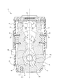
- FIG. 3 is a cross-sectional view showing a part of the drive device shown in FIG. 3 in a state when the screwed portion is in the non-screwed position.
- FIG. 3 is a cross-sectional view showing a part of the drive device shown in FIG. 3 in a state when the screwed portion is in the screwed position. It is explanatory drawing which shows the contour shape in the cross section of the bearing part and the shaft member of two nut members shown in FIG.
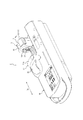
- the drive device 1 constitutes a medical pump 2.
- the medical pump 2 is a syringe pump, but is not limited to this, and may be, for example, an infusion pump, a nutrition pump, an insulin pump, a blood pump, or the like.
- FIG. 2 shows the drive device 1 in the upside-down and left-right directions with respect to FIG.
- the drive device 1 has a drive source 3, a feed screw 4, and a guided member 5.
- the drive source 3 is composed of, for example, an electric motor, and generates power for rotating the feed screw 4.
- the drive source 3 rotates the feed screw 4 around the central axis Z1 via a power transmission device 6 composed of a gear train.
- the power transmission device 6 is not limited to the one composed of a gear train.
- the lead screw 4 has a central axis Z1 and a male screw portion 4a that spirally orbits around the central axis Z1.
- the guided member 5 is configured to be guided by the guide member 7 in the axial direction Dz along the central axis Z1.
- the guide member 7 is composed of three rod members 7a extending in the axial direction Dz and a guide cylinder portion 7b.
- the guided member 5 has a housing 8 that slides with respect to the three rod members 7a, and a hollow shaft 9 that slides with respect to the guide cylinder portion 7b.
- the structure for guiding the guided member 5 in the axial direction Dz is not limited to this.
- the guided member 5 has an end member 10 and a switching member 11.
- One end of the hollow shaft 9 is connected to the housing 8, and the other end of the hollow shaft 9 is connected to the end member 10.
- the switching member 11 has an operating member 12.
- the operating member 12 is rotatably supported by the end member 10 around the rotation axis Z2.
- the end member 10 has a pressing portion 13 that presses a syringe pusher (not shown) in the axial direction Dz. Further, the end member 10 is provided with a fixing member 14 composed of a pressing portion 13 and two arm members arranged so as to face the axial direction Dz.
- the fixing member 14 opens in conjunction with the operating member 12 by operating the operating member 12 and rotating in the direction of the white arrow in FIG. 1, and releases the fixing of the pusher, while operating as shown in FIG. By returning the member 12, it closes in conjunction with the operating member 12, and the pusher is fixed.
- the pusher is fixed to the end member 10 by sandwiching the end flange of the pusher between the pressing portion 13 and the closed fixing member 14.
- the configuration of the fixing member 14 can be changed as appropriate.
- the fixing member 14 may not be provided.
- the medical pump 2 has a case 16 provided with a mounting portion 15 on which a syringe body into which a pusher is pushed is mounted.
- the syringe is composed of a syringe body and an pusher.
- a fixing lever 17 is provided in a portion adjacent to the mounting portion 15.
- the fixed lever 17 is mounted on the mounting portion 15 by rotating the fixing lever 17 to rotate the eaves portion 17a of the fixed lever 17 to a position facing the mounting portion 15 as shown in FIG. While fixing the syringe body, the fixing lever 17 is rotated to rotate the eaves portion 17a of the fixing lever 17 to a position not facing the mounting portion 15, thereby fixing the syringe body mounted on the mounting portion 15. Is configured to release.
- the configuration of the fixing lever 17 can be changed as appropriate.
- the fixed lever 17 may not be provided.
- FIG. 3 shows a part of the guided member 5 of the drive device 1 disassembled in the direction in which the left and right sides are reversed with respect to FIG.
- the switching member 11 includes an operating member 12, a cam shaft 18, a cam 19, and a ring member 20.
- the cam shaft 18 is a shaft member having the rotation axis Z2 as the central axis, and penetrates the hollow portion of the hollow shaft 9.
- One end of the cam shaft 18 is integrally rotatably connected to the operating member 12.
- a cam 19 is integrally rotatably connected to a portion of the cam shaft 18 that protrudes from the hollow shaft 9 on the other end side.
- the ring member 20 is fixed to the other end of the cam shaft 18 by, for example, a fastener that is screwed into two screw holes 20a that penetrate the ring member 20 in the radial direction and abuts on the outer peripheral surface of the cam shaft 18. There is.
- the guided member 5 has two nut members 21.
- Each nut member 21 has a screw portion 22 that is screwed with the male screw portion 4a of the feed screw 4.
- FIG. 4 is an exploded perspective view of the two nut members 21 and the cam 19 shown in FIG.
- FIG. 5 is a cross-sectional view showing a part of the drive device 1 shown in FIG. 3 in a state when the screwed portion 22 is in the non-screwed position.
- FIG. 6 is a cross-sectional view showing a part of the drive device 1 shown in FIG. 3 in a state when the screwed portion 22 is in the screwed position.
- the non-screw position is a position where the screw portion 22 does not screw with the feed screw 4.
- the screwing position is a position where the screwing portion 22 is screwed with the feed screw 4.
- the cross section is a cross section orthogonal to the central axis Z1.
- each nut member 21 has a bearing portion 23 that swivels the screw portion 22 so that the screw portion 22 moves in the direction toward the central axis Z1 in the cross section.
- the guided member 5 has a shaft member 24 that can be received by both the bearing portions 23 of the two nut members 21.
- the cam 19 is arranged so as to be sandwiched between the two nut members 21 so as to slide with respect to each of the portions between the screwed portion 22 and the bearing portion 23 of the two nut members 21.
- the housing 8 has a box shape having an opening portion 8a having an opening into which two nut members 21 sandwiching the cam 19 can be inserted on the upper surface in FIG. 3, and two nuts. It houses the member 21.
- the housing 8 may be changed to a member having a shape that does not accommodate the two nut members 21.
- Each of the two surfaces of the housing 8 facing the axial Dz has a shaft member through hole 25 through which the shaft member 24 penetrates.
- the shaft member 24 is composed of a headed pin.
- Each of the two surfaces of the housing 8 facing the axial direction Dz has a camshaft through hole 26 through which the camshaft 18 penetrates.
- the other end side region including the other end of the cam shaft 18 has a non-circular cross-sectional shape that fits with the cam hole 19a penetrating the cam 19.
- the cam 19 sandwiched between the two nut members 21 and housed in the housing 8 the other end side region of the cam shaft 18 is passed through the two cam shaft through holes 26 of the housing 8 and the cam hole 19a of the cam 19.
- the camshaft 18 is attached to the housing 8 by fixing the ring member 20 to the other end of the camshaft 18.
- the mounting structure for mounting the camshaft 18 to the housing 8 can be changed as appropriate.
- each of the two surfaces of the housing 8 facing the axial direction Dz has a feed screw through hole 27 through which the feed screw 4 penetrates and a rod member through hole 28 through which one of the three rod members 7a penetrates.
- Have. Sliding contact portions 8b are provided on each of the outer surfaces of the two corner portions located at the lower right and lower left of the housing 8 in FIG. The two sliding contact portions 8b are in sliding contact with the remaining two of the three rod members 7a, one by one.
- the drive device 1 has two coil-shaped springs 29 as urging members that urge the two screwed portions 22 in the direction toward the central axis Z1.
- Each of the two surfaces of the housing 8 facing in the left-right direction in FIG. 3 has a spring through hole 30 through which the spring 29 penetrates.
- Each of the two springs 29 urges the threaded portion 22 in the direction toward the central axis Z1.
- the structure for arranging the two springs 29 can be changed as appropriate.
- the two springs 29 are not limited to the coil shape.
- the urging member is not limited to the two springs 29.
- the drive device 1 may have no urging member.
- the switching member 11 slides with respect to the two nut members 21 by rotating the cam 19 around the rotation axis Z2, so that the positions of the two screwed portions 22 are the screwed positions shown in FIG. It switches between the non-screw position shown in FIG. In FIG. 5, the positions of the two screwed portions 22 are switched from the screwed position to the non-screwed position by rotating the cam 19 counterclockwise.
- the guided member 5 can be moved in the axial direction Dz by rotating the feed screw 4 by the drive source 3, so that the pressing portion 13 pushes the pusher into the syringe body. It can be pushed in and the liquid can be extruded from inside the syringe body.
- the user can grab the guided member 5 and freely move in the axial direction Dz, so that when attaching a syringe having a desired size to the medical pump 2.
- the pusher can be easily attached to the pressing portion 13 of the guided member 5.
- each screwed portion 22 moves in the direction toward the central axis Z1 when moving from the non-screwed position to the screwed position. Therefore, even if the relative positions of the lead screw 4 and the respective screw portions 22 in the cross section vary due to thermal expansion of the component parts, manufacturing errors, etc., the feed screw 4 and each screw portion caused by the variation, etc. Since each screw portion 22 can move in the direction toward the central axis Z1 in the cross section so as to narrow the gap between the screw portion 22 and the feed screw 4, the misalignment of each screw portion 22 with respect to the feed screw 4 can be reduced. Therefore, the accuracy of movement of the guided member 5, that is, the axial Dz of the pusher of the syringe can be improved.
- the drive device 1 of the present embodiment further reduces the misalignment of each screwed portion 22 with respect to the feed screw 4, thereby moving the guided member 5 with high accuracy.
- the bearing portion 23 of each nut member 21 has a long hole shape in the cross section in a direction substantially orthogonal to the direction in which the screwed portion 22 faces the central axis Z1. That is, each bearing portion 23 has a short axis O1 and a long axis O2 orthogonal to each other, and the long axis O2 is in a direction substantially orthogonal to the direction in which the screwed portion 22 is directed toward the central axis Z1 (FIG. 6). Extends in the vertical direction).
- FIG. 7 shows the contour shape of the bearing portion 23 and the shaft member 24 of the two nut members 21 shown in FIG. 3 in the cross section.
- the contour of the shaft member 24 is substantially a perfect circle
- the contour of the bearing portion 23 is a substantially elliptical shape having a short axis O1 and a long axis O2, that is, a straight line between semi-arcs. It is a shape tied with.
- the contour shapes of the shaft member 24 and the bearing portion 23 are not limited to this.
- the extending direction of the long axis O2 is not limited to the direction in which the screwed portion 22 is substantially orthogonal to the direction toward the central axis Z1, and the screwed portion 22 may intersect with the direction toward the central axis Z1. With such a configuration, each screwed portion 22 can be moved not only in the direction toward the central axis Z1 but also in the direction intersecting the direction, and the misalignment of each screwed portion 22 with respect to the feed screw 4 Can be further reduced.
- bearing portions 23 of the two nut members 21 can move individually with respect to the shaft member 24, for example, one bearing portion 23 rises and the other bearing portion 23 descends, so that each of the feed screws 4 can be moved individually.
- the misalignment of the screwed portion 22 of the above can be further reduced.
- the short shaft O1 corresponds to "gap fitting" (for example, light rolling or rolling in JIS B 0401-1, -2 (1998)) in which parts can move relative to the shaft member 24 as a general fitting.
- the major axis O2 has a length exceeding this length. For example, it is possible to set a gap of several tens of microns in the minor axis O1 direction and a gap of several hundred microns in the major axis O2 direction. With such a setting, each screwed portion 22 can be moved not only in the direction toward the central axis Z1 but also in the direction intersecting the direction, so that the misaligned portion 22 with respect to the feed screw 4 is displaced. When the position of each screwed portion 22 is switched to the non-screwed position by the cam 19, it is difficult for each bearing portion 23 to move, and each screwed portion 22 is centered. It can move smoothly in the direction away from the axis Z1.
- the cam 19 has two cam surfaces 19b that face each other with the rotation axis Z2 in between. Each cam surface 19b slides with respect to a portion of the nut member 21 between the screwed portion 22 and the bearing portion 23. As shown in FIG. 5, the one nut member 21 to which one cam surface 19b closer to the central axis Z1 is in sliding contact has a shorter overall length than the other nut member 21. That is, the bearing portion 23 of one nut member 21 is arranged on the side where the screw portion 22 of one nut member 21 is located with respect to the straight line L passing through the central axis Z1 and the rotation axis Z2 in the cross section. ing.
- the bearing portion 23 and the shaft member 24 of the two nut members 21 are arranged on the left side of the straight line L in FIG. With such a setting, the balance of the forces when the two nut members 21 are pushed open by the cam 19 is improved, and the positions of the two screwed portions 22 can be smoothly switched.
- the arrangement of the bearing portion 23 and the shaft member 24 is not limited to this.
- the two nut members 21, the cam 19, and the housing 8 can be made of synthetic resin, and the feed screw 4, the shaft member 24, the cam shaft 18, and the ring member 20 can be made of metal.
- a synthetic resin instead of a metal, the manufacturing cost of the member can be reduced, and the weight can be reduced.
- the synthetic resin constituting the two nut members 21, the cam 19 and the housing 8 include polyetheretherketone (PEEK), polyphenylene sulfide (PPS), and the like.
- PEEK polyetheretherketone
- PPS polyphenylene sulfide
- the feed screw 4 and the screwed portion 22 in the cross section are more closely connected than when they are made of metal.
- the relative position tends to vary due to the difference in the coefficient of linear thermal expansion of the components due to the change in ambient temperature.
- the two nut members 21 and the like are formed by injection molding using synthetic resin, the variation in the dimensions of the individual members becomes larger than in the case where the two nut members 21 and the like are formed by cutting using metal. Therefore, as in the present embodiment, the configuration in which the screwed portion 22 moves in both the direction toward the central axis z1 and the direction intersecting the central axis z1 in the cross section has the same material configuration as described above. Especially suitable when
- the drive device 1 has two position sensors 32 that detect the position of the screwed portion 22.
- Each position sensor 32 has a transmitting unit 32a for transmitting a signal such as light and a receiving unit 32b for receiving the signal.
- Each nut member 21 has a blocking plate 21a that blocks a signal when the nut member 21 is located at either the screwed position or the non-threaded position. According to such a configuration, the screwed state of the screwed portion 22 can be monitored, so that the safety can be improved.
- the two position sensors 32 are mounted on the board 33. As shown in FIGS. 2 to 3, the substrate 33 is attached to the housing 8 with two position sensors 32 located in the housing 8 and the substrate 33 arranged so as to cover the open portion 8a of the housing 8. There is.
- the number of the position sensor 32 and the blocking plate 21a is not limited to two, and may be one. The position sensor 32 and the blocking plate 21a may not be provided.
- the two nut members 21 are rotatably supported by a common shaft member 24, but the present invention is not limited to this, and the two nut members 21 may be rotatably supported by individual shafts. In the above-described embodiment, two nut members 21 are provided, but the number of nut members 21 is not limited to this, and may be one, for example.
- the nut member 21 has a bearing portion 23 supported by the shaft member 24, but the present invention is not limited to this, and the nut member 21 may have a shaft supported by the bearing portion.
- the nut member 21 is configured to rotate so that the screwed portion 22 moves in the direction toward the central axis Z1 in the cross section.
- the present invention is not limited to this, and for example, the screwed portion 22 has a cross section.
- the nut member 21 may be translated so as to move in the direction toward the central axis Z1.
- the nut member 21 also moves in the direction in which the nut member 21 intersects the above-mentioned translation direction so that the screwed portion 22 moves in the direction intersecting the direction toward the central axis Z1 in the cross section. It can be configured to be.
- the switching member 11 has a cam 19, but the present invention is not limited to this. Further, the drive device 1 may be configured not to have the switching member 11.
Landscapes
- Health & Medical Sciences (AREA)
- Engineering & Computer Science (AREA)
- Hematology (AREA)
- Life Sciences & Earth Sciences (AREA)
- Vascular Medicine (AREA)
- Anesthesiology (AREA)
- Biomedical Technology (AREA)
- Heart & Thoracic Surgery (AREA)
- Veterinary Medicine (AREA)
- Public Health (AREA)
- Animal Behavior & Ethology (AREA)
- General Health & Medical Sciences (AREA)
- General Engineering & Computer Science (AREA)
- Mechanical Engineering (AREA)
- Transmission Devices (AREA)
- Infusion, Injection, And Reservoir Apparatuses (AREA)
Priority Applications (4)
| Application Number | Priority Date | Filing Date | Title |
|---|---|---|---|
| JP2021537390A JP7449293B2 (ja) | 2019-08-07 | 2020-08-06 | 駆動装置及び医療用ポンプ |
| EP20849163.9A EP4006384B1 (en) | 2019-08-07 | 2020-08-06 | Drive device and medical pump |
| CN202080015777.9A CN113454366B (zh) | 2019-08-07 | 2020-08-06 | 驱动装置以及医疗用泵 |
| US17/590,573 US20220152293A1 (en) | 2019-08-07 | 2022-02-01 | Drive device and medical infusion pump |
Applications Claiming Priority (2)
| Application Number | Priority Date | Filing Date | Title |
|---|---|---|---|
| JP2019145705 | 2019-08-07 | ||
| JP2019-145705 | 2019-08-07 |
Related Child Applications (1)
| Application Number | Title | Priority Date | Filing Date |
|---|---|---|---|
| US17/590,573 Continuation US20220152293A1 (en) | 2019-08-07 | 2022-02-01 | Drive device and medical infusion pump |
Publications (1)
| Publication Number | Publication Date |
|---|---|
| WO2021025132A1 true WO2021025132A1 (ja) | 2021-02-11 |
Family
ID=74503877
Family Applications (1)
| Application Number | Title | Priority Date | Filing Date |
|---|---|---|---|
| PCT/JP2020/030255 Ceased WO2021025132A1 (ja) | 2019-08-07 | 2020-08-06 | 駆動装置及び医療用ポンプ |
Country Status (5)
| Country | Link |
|---|---|
| US (1) | US20220152293A1 (https=) |
| EP (1) | EP4006384B1 (https=) |
| JP (1) | JP7449293B2 (https=) |
| CN (1) | CN113454366B (https=) |
| WO (1) | WO2021025132A1 (https=) |
Cited By (2)
| Publication number | Priority date | Publication date | Assignee | Title |
|---|---|---|---|---|
| WO2022253978A1 (de) * | 2021-06-02 | 2022-12-08 | Ejot Se & Co. Kg | Spindelmutter und spindel-spindelmutter-anordnung |
| US20230105287A1 (en) * | 2021-10-06 | 2023-04-06 | Deka Products Limited Partnership | System and method for organ injection |
Citations (6)
| Publication number | Priority date | Publication date | Assignee | Title |
|---|---|---|---|---|
| JPS542110B2 (https=) * | 1972-05-26 | 1979-02-02 | ||
| JPS6366656U (https=) * | 1986-10-21 | 1988-05-06 | ||
| JP2011206376A (ja) | 2010-03-30 | 2011-10-20 | Terumo Corp | シリンジポンプ |
| WO2018046313A1 (en) * | 2016-09-07 | 2018-03-15 | Fresenius Vial Sas | Infusion device having a clutching device |
| JP2018075276A (ja) * | 2016-11-11 | 2018-05-17 | ミネベアミツミ株式会社 | シリンジポンプ |
| JP2019107424A (ja) * | 2017-12-20 | 2019-07-04 | ミネベアミツミ株式会社 | シリンジポンプおよびシリンジポンプの製造方法 |
Family Cites Families (15)
| Publication number | Priority date | Publication date | Assignee | Title |
|---|---|---|---|---|
| JPS63140159A (ja) * | 1986-12-03 | 1988-06-11 | Matsushita Electric Ind Co Ltd | 微小位置決め装置 |
| JPH08184742A (ja) * | 1994-12-28 | 1996-07-16 | Sony Corp | 送りネジ機構 |
| JP3933832B2 (ja) * | 1999-12-24 | 2007-06-20 | テルモ株式会社 | シリンジポンプ |
| US6387077B1 (en) * | 2000-10-13 | 2002-05-14 | Mallinckrodt Inc. | Apparatus and method for providing a suspended agent |
| JP2006349066A (ja) * | 2005-06-16 | 2006-12-28 | Nsk Ltd | 直動装置 |
| JP2012083202A (ja) * | 2010-10-12 | 2012-04-26 | Nikon Corp | 載物台用送り機構 |
| HU229852B1 (en) * | 2012-08-15 | 2014-10-28 | Hibar Systems Ltd Richmond Hill | Electronically controlled and driven linear pump actuator |
| JP6145398B2 (ja) * | 2013-12-18 | 2017-06-14 | 三菱重工業株式会社 | 直動機構、調整弁駆動装置、蒸気タービン |
| US20170258985A1 (en) * | 2014-12-02 | 2017-09-14 | Smiths Medical Asd, Inc. | Syringe infusion pump security |
| EP3359226B1 (en) * | 2015-10-05 | 2024-12-04 | Fresenius Vial SAS | Infusion device for administering a medical fluid to a patient and method for operating an infusion device |
| EP3393549B1 (en) * | 2015-12-21 | 2025-07-30 | Fresenius Vial SAS | Infusion device having a pusher device |
| JP6647900B2 (ja) * | 2016-02-09 | 2020-02-14 | Ntn株式会社 | 電動アクチュエータ |
| US10773024B2 (en) * | 2016-06-09 | 2020-09-15 | Becton, Dickinson And Company | Drive assembly for drug delivery system |
| CN109923332B (zh) * | 2016-11-07 | 2022-06-14 | 大陆汽车有限公司 | 直线驱动装置、马达以及直线驱动装置的制造方法 |
| JP2019107423A (ja) * | 2017-12-20 | 2019-07-04 | ミネベアミツミ株式会社 | シリンジポンプ |
-
2020
- 2020-08-06 JP JP2021537390A patent/JP7449293B2/ja active Active
- 2020-08-06 CN CN202080015777.9A patent/CN113454366B/zh active Active
- 2020-08-06 WO PCT/JP2020/030255 patent/WO2021025132A1/ja not_active Ceased
- 2020-08-06 EP EP20849163.9A patent/EP4006384B1/en active Active
-
2022
- 2022-02-01 US US17/590,573 patent/US20220152293A1/en active Pending
Patent Citations (6)
| Publication number | Priority date | Publication date | Assignee | Title |
|---|---|---|---|---|
| JPS542110B2 (https=) * | 1972-05-26 | 1979-02-02 | ||
| JPS6366656U (https=) * | 1986-10-21 | 1988-05-06 | ||
| JP2011206376A (ja) | 2010-03-30 | 2011-10-20 | Terumo Corp | シリンジポンプ |
| WO2018046313A1 (en) * | 2016-09-07 | 2018-03-15 | Fresenius Vial Sas | Infusion device having a clutching device |
| JP2018075276A (ja) * | 2016-11-11 | 2018-05-17 | ミネベアミツミ株式会社 | シリンジポンプ |
| JP2019107424A (ja) * | 2017-12-20 | 2019-07-04 | ミネベアミツミ株式会社 | シリンジポンプおよびシリンジポンプの製造方法 |
Non-Patent Citations (1)
| Title |
|---|
| See also references of EP4006384A4 |
Cited By (2)
| Publication number | Priority date | Publication date | Assignee | Title |
|---|---|---|---|---|
| WO2022253978A1 (de) * | 2021-06-02 | 2022-12-08 | Ejot Se & Co. Kg | Spindelmutter und spindel-spindelmutter-anordnung |
| US20230105287A1 (en) * | 2021-10-06 | 2023-04-06 | Deka Products Limited Partnership | System and method for organ injection |
Also Published As
| Publication number | Publication date |
|---|---|
| JPWO2021025132A1 (https=) | 2021-02-11 |
| JP7449293B2 (ja) | 2024-03-13 |
| US20220152293A1 (en) | 2022-05-19 |
| CN113454366B (zh) | 2023-08-08 |
| EP4006384A4 (en) | 2022-09-14 |
| CN113454366A (zh) | 2021-09-28 |
| EP4006384A1 (en) | 2022-06-01 |
| EP4006384B1 (en) | 2025-07-23 |
Similar Documents
| Publication | Publication Date | Title |
|---|---|---|
| JP6937563B2 (ja) | 車両用ドア開閉装置 | |
| JP5340640B2 (ja) | 電動リニアアクチュエータ | |
| US6178837B1 (en) | Electric actuator | |
| WO2021025132A1 (ja) | 駆動装置及び医療用ポンプ | |
| US4957274A (en) | Position sensor for a rotary valve | |
| US20150197231A1 (en) | Electric Brake Booster with Transmission Clearance Compensation | |
| US20230001787A1 (en) | Accelerator device | |
| US8924045B2 (en) | Device for adjusting and locking a movable control surface | |
| US11408531B2 (en) | Spool valve | |
| KR20030003738A (ko) | 클러치 액츄에이터 유닛 | |
| CN112807526A (zh) | 注射泵 | |
| US20200039094A1 (en) | Rotary actuator and robot | |
| US7481126B2 (en) | Precision table | |
| CN111373183B (zh) | 滑阀 | |
| JP6609168B2 (ja) | バルブアクチュエータ | |
| US20090133518A1 (en) | Motion converter | |
| US4873542A (en) | Auto-focus camera | |
| EP3733480A1 (en) | Ball screw device and steering device | |
| US7520192B2 (en) | Reduced-friction drive screw assembly | |
| CN211486025U (zh) | 注射泵的泵体装置及注射泵 | |
| CA2794494A1 (en) | Electric cylinder | |
| US20080250921A1 (en) | Stroke adjustment mechanism for reciprocating pumps | |
| KR20150050841A (ko) | 평활축 베어링 스크류 이송장치 | |
| CN112807527A (zh) | 注射泵的泵体装置及注射泵 | |
| CN211486023U (zh) | 注射泵 |
Legal Events
| Date | Code | Title | Description |
|---|---|---|---|
| 121 | Ep: the epo has been informed by wipo that ep was designated in this application |
Ref document number: 20849163 Country of ref document: EP Kind code of ref document: A1 |
|
| ENP | Entry into the national phase |
Ref document number: 2021537390 Country of ref document: JP Kind code of ref document: A |
|
| NENP | Non-entry into the national phase |
Ref country code: DE |
|
| ENP | Entry into the national phase |
Ref document number: 2020849163 Country of ref document: EP Effective date: 20220228 |
|
| WWG | Wipo information: grant in national office |
Ref document number: 2020849163 Country of ref document: EP |