WO2021025042A1 - 電気刺激フィットネスウェア - Google Patents
電気刺激フィットネスウェア Download PDFInfo
- Publication number
- WO2021025042A1 WO2021025042A1 PCT/JP2020/029934 JP2020029934W WO2021025042A1 WO 2021025042 A1 WO2021025042 A1 WO 2021025042A1 JP 2020029934 W JP2020029934 W JP 2020029934W WO 2021025042 A1 WO2021025042 A1 WO 2021025042A1
- Authority
- WO
- WIPO (PCT)
- Prior art keywords
- control unit
- electrode
- electrode portion
- upper body
- garment
- Prior art date
Links
Images


Classifications
-
- A—HUMAN NECESSITIES
- A61—MEDICAL OR VETERINARY SCIENCE; HYGIENE
- A61N—ELECTROTHERAPY; MAGNETOTHERAPY; RADIATION THERAPY; ULTRASOUND THERAPY
- A61N1/00—Electrotherapy; Circuits therefor
- A61N1/02—Details
- A61N1/04—Electrodes
- A61N1/0404—Electrodes for external use
- A61N1/0472—Structure-related aspects
- A61N1/0484—Garment electrodes worn by the patient
-
- A—HUMAN NECESSITIES
- A61—MEDICAL OR VETERINARY SCIENCE; HYGIENE
- A61N—ELECTROTHERAPY; MAGNETOTHERAPY; RADIATION THERAPY; ULTRASOUND THERAPY
- A61N1/00—Electrotherapy; Circuits therefor
- A61N1/02—Details
- A61N1/04—Electrodes
- A61N1/0404—Electrodes for external use
- A61N1/0408—Use-related aspects
- A61N1/0452—Specially adapted for transcutaneous muscle stimulation [TMS]
-
- A—HUMAN NECESSITIES
- A41—WEARING APPAREL
- A41D—OUTERWEAR; PROTECTIVE GARMENTS; ACCESSORIES
- A41D1/00—Garments
- A41D1/002—Garments adapted to accommodate electronic equipment
-
- A—HUMAN NECESSITIES
- A41—WEARING APPAREL
- A41D—OUTERWEAR; PROTECTIVE GARMENTS; ACCESSORIES
- A41D1/00—Garments
- A41D1/002—Garments adapted to accommodate electronic equipment
- A41D1/005—Garments adapted to accommodate electronic equipment with embedded cable or connector
-
- A—HUMAN NECESSITIES
- A41—WEARING APPAREL
- A41D—OUTERWEAR; PROTECTIVE GARMENTS; ACCESSORIES
- A41D13/00—Professional, industrial or sporting protective garments, e.g. surgeons' gowns or garments protecting against blows or punches
- A41D13/0015—Sports garments other than provided for in groups A41D13/0007 - A41D13/088
-
- A—HUMAN NECESSITIES
- A41—WEARING APPAREL
- A41D—OUTERWEAR; PROTECTIVE GARMENTS; ACCESSORIES
- A41D27/00—Details of garments or of their making
-
- A—HUMAN NECESSITIES
- A61—MEDICAL OR VETERINARY SCIENCE; HYGIENE
- A61N—ELECTROTHERAPY; MAGNETOTHERAPY; RADIATION THERAPY; ULTRASOUND THERAPY
- A61N1/00—Electrotherapy; Circuits therefor
- A61N1/02—Details
- A61N1/04—Electrodes
- A61N1/0404—Electrodes for external use
- A61N1/0472—Structure-related aspects
- A61N1/0476—Array electrodes (including any electrode arrangement with more than one electrode for at least one of the polarities)
-
- A—HUMAN NECESSITIES
- A61—MEDICAL OR VETERINARY SCIENCE; HYGIENE
- A61N—ELECTROTHERAPY; MAGNETOTHERAPY; RADIATION THERAPY; ULTRASOUND THERAPY
- A61N1/00—Electrotherapy; Circuits therefor
- A61N1/18—Applying electric currents by contact electrodes
- A61N1/32—Applying electric currents by contact electrodes alternating or intermittent currents
- A61N1/36—Applying electric currents by contact electrodes alternating or intermittent currents for stimulation
- A61N1/36003—Applying electric currents by contact electrodes alternating or intermittent currents for stimulation of motor muscles, e.g. for walking assistance
-
- A—HUMAN NECESSITIES
- A61—MEDICAL OR VETERINARY SCIENCE; HYGIENE
- A61N—ELECTROTHERAPY; MAGNETOTHERAPY; RADIATION THERAPY; ULTRASOUND THERAPY
- A61N1/00—Electrotherapy; Circuits therefor
- A61N1/18—Applying electric currents by contact electrodes
- A61N1/32—Applying electric currents by contact electrodes alternating or intermittent currents
- A61N1/36—Applying electric currents by contact electrodes alternating or intermittent currents for stimulation
- A61N1/36014—External stimulators, e.g. with patch electrodes
- A61N1/3603—Control systems
- A61N1/36031—Control systems using physiological parameters for adjustment
-
- D—TEXTILES; PAPER
- D03—WEAVING
- D03D—WOVEN FABRICS; METHODS OF WEAVING; LOOMS
- D03D1/00—Woven fabrics designed to make specified articles
- D03D1/0088—Fabrics having an electronic function
-
- D—TEXTILES; PAPER
- D03—WEAVING
- D03D—WOVEN FABRICS; METHODS OF WEAVING; LOOMS
- D03D15/00—Woven fabrics characterised by the material, structure or properties of the fibres, filaments, yarns, threads or other warp or weft elements used
- D03D15/20—Woven fabrics characterised by the material, structure or properties of the fibres, filaments, yarns, threads or other warp or weft elements used characterised by the material of the fibres or filaments constituting the yarns or threads
- D03D15/242—Woven fabrics characterised by the material, structure or properties of the fibres, filaments, yarns, threads or other warp or weft elements used characterised by the material of the fibres or filaments constituting the yarns or threads inorganic, e.g. basalt
- D03D15/25—Metal
-
- D—TEXTILES; PAPER
- D03—WEAVING
- D03D—WOVEN FABRICS; METHODS OF WEAVING; LOOMS
- D03D15/00—Woven fabrics characterised by the material, structure or properties of the fibres, filaments, yarns, threads or other warp or weft elements used
- D03D15/40—Woven fabrics characterised by the material, structure or properties of the fibres, filaments, yarns, threads or other warp or weft elements used characterised by the structure of the yarns or threads
- D03D15/47—Woven fabrics characterised by the material, structure or properties of the fibres, filaments, yarns, threads or other warp or weft elements used characterised by the structure of the yarns or threads multicomponent, e.g. blended yarns or threads
-
- D—TEXTILES; PAPER
- D03—WEAVING
- D03D—WOVEN FABRICS; METHODS OF WEAVING; LOOMS
- D03D15/00—Woven fabrics characterised by the material, structure or properties of the fibres, filaments, yarns, threads or other warp or weft elements used
- D03D15/50—Woven fabrics characterised by the material, structure or properties of the fibres, filaments, yarns, threads or other warp or weft elements used characterised by the properties of the yarns or threads
- D03D15/533—Woven fabrics characterised by the material, structure or properties of the fibres, filaments, yarns, threads or other warp or weft elements used characterised by the properties of the yarns or threads antistatic; electrically conductive
-
- D—TEXTILES; PAPER
- D03—WEAVING
- D03D—WOVEN FABRICS; METHODS OF WEAVING; LOOMS
- D03D15/00—Woven fabrics characterised by the material, structure or properties of the fibres, filaments, yarns, threads or other warp or weft elements used
- D03D15/60—Woven fabrics characterised by the material, structure or properties of the fibres, filaments, yarns, threads or other warp or weft elements used characterised by the warp or weft elements other than yarns or threads
- D03D15/67—Metal wires
-
- D—TEXTILES; PAPER
- D10—INDEXING SCHEME ASSOCIATED WITH SUBLASSES OF SECTION D, RELATING TO TEXTILES
- D10B—INDEXING SCHEME ASSOCIATED WITH SUBLASSES OF SECTION D, RELATING TO TEXTILES
- D10B2101/00—Inorganic fibres
- D10B2101/20—Metallic fibres
-
- D—TEXTILES; PAPER
- D10—INDEXING SCHEME ASSOCIATED WITH SUBLASSES OF SECTION D, RELATING TO TEXTILES
- D10B—INDEXING SCHEME ASSOCIATED WITH SUBLASSES OF SECTION D, RELATING TO TEXTILES
- D10B2211/00—Protein-based fibres, e.g. animal fibres
- D10B2211/01—Natural animal fibres, e.g. keratin fibres
- D10B2211/04—Silk
-
- D—TEXTILES; PAPER
- D10—INDEXING SCHEME ASSOCIATED WITH SUBLASSES OF SECTION D, RELATING TO TEXTILES
- D10B—INDEXING SCHEME ASSOCIATED WITH SUBLASSES OF SECTION D, RELATING TO TEXTILES
- D10B2331/00—Fibres made from polymers obtained otherwise than by reactions only involving carbon-to-carbon unsaturated bonds, e.g. polycondensation products
- D10B2331/02—Fibres made from polymers obtained otherwise than by reactions only involving carbon-to-carbon unsaturated bonds, e.g. polycondensation products polyamides
-
- D—TEXTILES; PAPER
- D10—INDEXING SCHEME ASSOCIATED WITH SUBLASSES OF SECTION D, RELATING TO TEXTILES
- D10B—INDEXING SCHEME ASSOCIATED WITH SUBLASSES OF SECTION D, RELATING TO TEXTILES
- D10B2331/00—Fibres made from polymers obtained otherwise than by reactions only involving carbon-to-carbon unsaturated bonds, e.g. polycondensation products
- D10B2331/30—Fibres made from polymers obtained otherwise than by reactions only involving carbon-to-carbon unsaturated bonds, e.g. polycondensation products polycondensation products not covered by indexing codes D10B2331/02 - D10B2331/14
-
- D—TEXTILES; PAPER
- D10—INDEXING SCHEME ASSOCIATED WITH SUBLASSES OF SECTION D, RELATING TO TEXTILES
- D10B—INDEXING SCHEME ASSOCIATED WITH SUBLASSES OF SECTION D, RELATING TO TEXTILES
- D10B2401/00—Physical properties
- D10B2401/16—Physical properties antistatic; conductive
-
- D—TEXTILES; PAPER
- D10—INDEXING SCHEME ASSOCIATED WITH SUBLASSES OF SECTION D, RELATING TO TEXTILES
- D10B—INDEXING SCHEME ASSOCIATED WITH SUBLASSES OF SECTION D, RELATING TO TEXTILES
- D10B2501/00—Wearing apparel
- D10B2501/04—Outerwear; Protective garments
-
- D—TEXTILES; PAPER
- D10—INDEXING SCHEME ASSOCIATED WITH SUBLASSES OF SECTION D, RELATING TO TEXTILES
- D10B—INDEXING SCHEME ASSOCIATED WITH SUBLASSES OF SECTION D, RELATING TO TEXTILES
- D10B2501/00—Wearing apparel
- D10B2501/06—Details of garments
Definitions
- the present invention relates to exercise clothing.
- the muscle electrical stimulator is expected to exercise the muscles and strengthen the muscles by applying a weak electric current to the muscles to tension and relax the muscles (see, for example, Patent Document 1).
- the present invention has been made in view of such a situation, and an object of the present invention is to provide fitness wear that maintains aesthetics and functionality.
- the electrically stimulating fitness wear of an aspect of the present invention is close to each of a garment portion that can be worn on the body and a plurality of target body parts in order to apply electrical stimulation to a plurality of target body parts.
- a plurality of electrode portions provided on the clothing portion at positions facing each of a plurality of target body parts and having a surface formed of a conductive polymer cloth, and a control unit for controlling the voltage of the plurality of electrode portions.
- a connection unit that is electrically connected to the control unit, and a plurality of electric wires that electrically connect each of the plurality of electrode units to the connection unit are provided.
- All or part of the garment portion has a multi-layer structure in which a plurality of fabrics are overlapped, and has a closed space formed by sewing all or a part of the surrounding fabrics between the plurality of fabrics.
- the plurality of electric wires include a first electric wire and a second electric wire, and are arranged in a closed space.
- the plurality of electrode portions are a first electrode portion to which the first electric wire is connected and a second electric wire.
- the first electrode portion and the second electrode portion include a second electrode portion to which the two electrodes are connected, and the first electrode portion and the second electrode portion are provided at positions separated from each other so that a predetermined body part can be energized.
- This electrical stimulation fitness wear has elastic clothing that can be worn on the body and multiple target body parts so that they can be close to each of the plurality of target body parts in order to apply electrical stimulation to the plurality of target body parts.
- a plurality of electrode portions provided at positions facing each other, a connection portion electrically connected to a control unit for controlling the voltage of the plurality of electrode portions, and each of the plurality of electrode portions and the connection portion are electrically connected. It is equipped with a plurality of stretchable electric wires to be connected to.
- An aspect of electrical stimulation fitness wear is provided on each of a wearable garment and a plurality of target body parts so that they can be close to each of the plurality of target body parts in order to provide electrical stimulation to the plurality of target body parts.
- a plurality of electrode portions whose surfaces are formed of a conductive polymer cloth, which are provided on the clothing portion at opposite positions, and a control unit that controls the voltage of the plurality of electrode portions are electrically connected to the control unit. It is provided with a connecting portion and a plurality of electric wires for electrically connecting each of the plurality of electrode portions and the connecting portion.
- All or part of the garment portion has a multi-layer structure in which a plurality of fabrics are overlapped, and has a closed space formed by sewing all or a part of the surrounding fabrics between the plurality of fabrics.
- the plurality of electric wires include a first electric wire and a second electric wire, and are arranged in a closed space.
- the plurality of electrode portions are a first electrode portion to which the first electric wire is connected and a second electric wire.
- the first electrode portion and the second electrode portion include a second electrode portion to which the two electrodes are connected, and the first electrode portion and the second electrode portion are provided at positions separated from each other so that a predetermined body part can be energized.
- the "control unit” referred to here may be a removable independent control unit, or may be a control device fixedly attached to the "connection unit".
- the "electric wire” may be an electric cable composed of a coated conductive wire or the like, or may have water resistance. Since the surface of the electrode portion is formed of a conductive polymer cloth, the electrode portion can be washed as it is as a part of the clothing portion without being removed from the clothing portion. In particular, as compared with the case of using conductive fibers containing a metal such as silver, there is no concern about deterioration of conductivity or metal allergy due to oxidation and corrosion.
- One of the first electrode portion and the second electrode portion is an anode and the other is a cathode, and they are provided at a certain distance so as to face the same target body part and energize between these electrode portions.
- electrical stimulation can be given to the target body part.
- the pair of yin and yang electrodes are physically separated and connected to separate electric wires, so that the fabric of the clothing part stretches according to the user's body shape and movement. Since the electrode position can be separated or moved in accordance with the extension of the electrode itself, it is possible to prevent the expansion and contraction of the clothing portion from being hindered even if the electrode itself does not have elasticity.
- the electric wire can be washed as it is as a part of the clothes part without removing it from the clothes part, and by arranging it in the closed space, the electric wire and the electrode can be hidden from the outside and the aesthetic appearance of the fitness wear can be maintained. Further, it is possible to prevent foreign matter from coming into contact with the electric wire or hindering expansion and contraction.
- Another aspect of the electrical stimulation fitness wear is a stretchable garment that can be worn on the body and a plurality of objects so that they can be close to each of the plurality of target body parts in order to apply electrical stimulation to the plurality of target body parts.
- a plurality of electrode portions provided at positions facing each of the body parts, a connection portion electrically connected to a control unit that controls the voltage of the plurality of electrode portions, and each of the plurality of electrode portions and the connection portion. It is equipped with a plurality of stretchable electric wires for electrically connecting the wires.
- the "electric wire” referred to here is a stretchable elastic core material in which one or a plurality of coated conductive wires formed by coating the core wire with a resin are wound around at least spirally around the stretchable elastic core material. It may be an electric cable.
- the elastic core material and the spirally wound coated lead wire are elastic in the longitudinal direction of the elastic core material, and the total length thereof can be extended up to, for example, about 1.4 times. Since such an electric wire can have both water resistance and elasticity, it can be washed as a part of the clothes part as it is without removing the electric wire from the clothes part, and also the clothes part depending on the user's body shape and movement.
- the electric wire can be stretched following the stretch, and it is possible to prevent the expansion and contraction of the garment portion from being hindered.
- it is not necessary to use a long electric wire that matches the elongation rate of the clothing portion it is possible to suppress a foreign body sensation caused by the extra electric wire hitting the user's body when the clothing portion contracts.
- At least a part of the garment portion may have a multi-layer structure in which a plurality of fabrics are overlapped, and may have a closed space formed by sewing at least a part of the periphery between the plurality of fabrics.
- the electric wire has elasticity that can expand and contract in accordance with the expansion and contraction of the garment portion, and a part thereof may be fixed to at least one predetermined fixing portion of the plurality of fabrics.
- the electrode portion may include a pad member provided on the side of the clothing portion facing the wearer's skin and a conductive polymer fabric covering the pad member.
- the electric wire may be connected to the conductive polymer fabric via a connector that penetrates the fabric of the garment portion and electrically connects the front and back surfaces.
- the "connector" may be a metal fastener such as a snap button, and the front and back surfaces of the fabric may be electrically connected by sandwiching the fabric of the clothing portion and the conductive polymer fabric.
- the garment portion is composed of a multi-layer structure in which a plurality of fabrics are stacked, an electric wire is wired inside the multi-layer structure and electrodes are provided on the outside of the multi-layer structure, that is, the side facing the wearer's skin. Even if these are provided, these can be easily electrically connected.
- the pad member by covering the pad member with a conductive polymer fabric to form an electrode, the electrode is prevented from being separated from the skin by protruding toward the skin by the pad member while maintaining a good feeling of contact with the skin. The contact state can be maintained.
- the fabric of the garment part has a multi-layer structure
- the lining can be deformed by the amount of the convex electrodes when the garment part is fitted to the user's body, but the deformation of the outer material is suppressed and the fitness wear You can keep the beauty of.
- the garment unit includes garments for the upper body and garments for the lower body, and each of the garments for the upper body and the garments for the lower body is provided with a plurality of electrode portions and a plurality of electric wires, and the garment portion serves as a control unit.
- a first control unit and a second control unit are attached, and the first control unit is attached to the first side of the left and right sides of the front of the clothing for the upper body with the midline as a boundary, and the second control unit is attached. May be attached to the second side of the front of the lower body garment, which is different from the first side of the left and right sides of the midline.
- the first control unit and the second control unit are installed separately for the upper body and the lower body, and are installed at positions separated to the left and right across the midline, so that the body can bend forward or the thighs or thighs. Even when the knee is lifted up, it is possible to prevent the first control unit and the second control unit from colliding with each other and interfering with each other. Further, since the control unit is divided into the first control unit and the second control unit and made independent, the intensity of the electrical stimulation to the upper body and the intensity of the electrical stimulation to the lower body can be set separately.
- the body while being given electrical stimulation from the electrical stimulation fitness wear worn by the user, the body is moved by itself according to the instruction according to the pattern of electrical stimulation, so that involuntary movements due to muscle electrical stimulation and involuntary movements are performed.
- hybrid training that combines voluntary movements that move the body consciously.
- the exercise effect can be enhanced by consciously moving the muscles in the opposite direction while applying electrical stimulation to the muscles. For example, an exercise that consciously applies a force to extend an arm (voluntary movement) while bending an elbow by electrical stimulation (involuntary movement) is performed.
- the muscle load can be increased efficiently in a shorter time than in normal exercise.
- the first exercise program is an exercise program performed by one user in a store such as a fitness gym according to an image on an individual display or an instruction of an instructor.
- the second exercise program is an exercise program performed by one user in a personal place such as a home according to instructions by a display image.
- the third exercise program is an exercise program in which a plurality of users simultaneously perform group training in a store such as a fitness gym according to the same video or the instruction of an instructor.
- the fourth exercise program is an exercise program in which one user in a personal place such as a home synchronizes with a user in another place according to the same video instruction provided via a network.
- the second and fourth exercise programs make it possible to carry out an exercise program equivalent to that of a fitness gym without going to a specific place such as a fitness gym, and it is possible to realize training that is not tied to time or environment.
- FIG. 1 shows the appearance of the motion control system.
- the motion control system mainly in the first movement program and the second movement program is shown.
- the motion control system includes one or more motion control devices 12 and one or more display devices.
- the exercise control device 12 in the first exercise program is installed in the fitness gym 80 and provides the exercise program to the user 82 who trains in the fitness gym 80.
- FIG. 1 shows an example in which an exercise control device 12a provides an exercise program to a user 82a and an exercise control device 12b provides an exercise program to a user 82b in a fitness gym 80. That is, there is a one-to-one relationship between the motion control device 12 and the user.
- the exercise control devices 12a and 12b are connected to the muscle electrical stimulators attached to the fitness wears 102a and 102b worn by the user via wireless communication to control the muscle electrical stimulators. Further, the motion control devices 12a and 12b are connected to the mirror displays 105a and 105b, respectively, control the display contents of the mirror displays 105a and 105b, and display an image showing a movement as a model.
- the motion control devices 12a and 12b are operated by the instructors 83a and 83b.
- the instructors 83a and 83b show model movements while verbally giving instructions and advice to the users 82a and 82b in the vicinity of the motion control devices 12a and 12b.
- the movement control devices 12a and 12b link the image of the movement as a model displayed on the mirror displays 105a and 105b with the voltage application to the muscle electrical stimulator of the fitness wears 102a and 102b to form an involuntary movement in hybrid training. Achieve synchronization of involuntary movements.
- the motion control devices 12a and 12b may be stand-alone, may be linked to each other via a network, or may be connected to a motion control management server via a network such as the Internet, and are based on instructions received from the motion control management server.
- An exercise program may be provided to each user.
- the motion control devices 12a and 12b cause each mirror display 105 to display individual contents at individual timings in order to individually provide an exercise program to a plurality of people.
- the exercise control device 12c provides the exercise program to the user 82 who trains in the personal space 81.
- FIG. 1 further shows an example of providing an exercise program to the user 82c in the personal space 81.
- the exercise control device 12c used in the personal space 81 is connected to the muscle electrical stimulator attached to the fitness wear 102c via wireless communication to control the muscle electrical stimulator.
- the motion control device 12c is an electronic device such as a tablet terminal that also serves as a display.
- the exercise control devices 12a to 12c may be connected to the exercise control management server via a network such as the Internet, and may provide the exercise program to each user 82 based on the instruction received from the exercise control management server.
- the motion control devices 12a to 12c cause each mirror display 105 and the motion control device 12c to display individual contents at individual timings in order to individually provide an exercise program to a plurality of people.
- the motion control devices 12a to 12c can start or end the exercise program of the muscle electrical stimulator by, for example, operating a button or a remote controller included in the muscle electrical stimulator without connecting to the motion control device 12 by wireless communication. Alternatively, the exercise program may be carried out independently without any instruction from the exercise control device 12.
- one exercise control device 12 and one display device 106 allow a plurality of users to be provided with the same exercise program all at once.
- the motion control device 12c connected via the network is further connected to the motion control device 12, and the same motion program is provided in synchronization with each other.
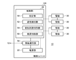
- FIG. 2 schematically shows the configuration of the movement control system in the first movement program and the second movement program.
- the motion control system 100 includes a plurality of fitness wears 102, a plurality of motion control devices 12, a plurality of mirror displays 105, and a motion control management server 16.
- the fitness wear 102 incorporates a plurality of electrodes as a muscle electrical stimulator, and a control unit is attached to the fitness wear 102.
- fitness wear 102a, 102b, exercise control devices 12a, 12b, mirror displays 105a, 105b, and exercise control management server 16 are installed or used in the fitness gym 80, of which fitness wear 102a, 102b is a user. Is lent to.
- the fitness wear 102c and the exercise control device 12c are used in the personal space 81, and are owned and used by the user himself, and are used in the fitness gym 80. It is different from the wear 102a, 102b, the motion control devices 12a, 12b, and the mirror displays 105a, 105b.
- the fitness wear 102a and the exercise control device 12a, and the fitness wear 102b and the exercise control device 12b are connected by short-range wireless communication 17 such as Bluetooth (registered trademark), respectively.
- the motion control devices 12a and 12b are connected to the mirror displays 105a and 105b by a wired cable, respectively.
- the mirror display 105 is configured by incorporating a monitor and a personal computer
- the motion control devices 12a and 12b are connected to the personal computer by a wired cable such as a LAN cable or a USB cable.
- the motion control devices 12a and 12b are connected to the monitor by a wired cable such as a monitor cable.
- the motion control devices 12a and 12b are connected to the motion control management server 16 by wired communication or wireless communication.
- each motion control device 12 may operate standalone, or may be connected to the motion control management server 16 but may operate individually without interlocking.
- one exercise control management server 16 installed in the fitness gym 80 controls all the exercise control devices 12 in the fitness gym 80.
- the motion control management server 16 may control the operation of all the motion control devices 12 and the muscle electrical stimulators.
- the exercise control management server 16 may be provided outside the fitness gym 80, for example, on the Internet.
- the fitness wear 102c and the exercise control device 12c are connected by short-range wireless communication 17 such as Bluetooth (registered trademark).
- the motion control device 12c exemplifies a tablet terminal that also serves as a display, but may be an information terminal such as a mobile phone or a personal computer connected to a monitor.
- a dedicated small terminal having the same function as the motion control devices 12a and 12b may be used.
- the motion control device 12c is connected to the network 15 by wireless communication or wired communication, and is connected to the motion control management server 16 via the network 15.
- the exercise program carried out in the fitness gym 80 can also be carried out in the personal space 81.
- a set or a plurality of sets of devices are installed in the fitness gym 80 with the motion control device 12 and the mirror display 105 as a set.
- One user uses these one set of devices, and one upper and lower set of fitness wear 102 is prepared for that user.
- the fitness wear 102 includes an upper body garment section and a lower body garment section.
- the fitness wear 102 has muscles on the back side (that is, the side that can come into contact with the user's skin) so that electrical stimulation can be applied to each body part such as the user's abdominal muscles, flanks, arms, legs, and buttocks. Electrodes of the electrical stimulator are provided.
- a control unit of a muscle electrical stimulator is attached to each of the upper body garment part and the lower body garment part of the fitness wear 102 to give electrical stimulation to the user's muscles.
- the muscle electrical stimulator includes a plurality of electrodes, cables, and a control unit, and the control unit communicates with the motion control device 12 by short-range wireless communication such as Bluetooth (registered trademark) to transmit and receive information.
- the control unit is attached to each of the upper body garment part and the lower body garment part, but as a modification, one control unit is attached to the upper body garment part or the lower body garment part as a whole of the fitness wear 102 combined up and down. It may be a specification that controls the application of electrical stimulation to the electrodes of the whole body.
- a motion control program instructed to start execution by communicating with the motion control device 12 controls voltage setting and operation in the muscle electrical stimulator.
- the display control device 104 displays the motion image on the display device 106 according to the instruction of the motion control program executed by the motion control device 12.
- the exercise control devices 12a and 12b are information terminals operated by the instructor or user of the fitness gym 80.
- the exercise control devices 12a and 12b control the intensity setting and operation of the electrical stimulation by the muscle electrical stimulation device provided in the fitness wears 102a and 102b via the control unit for each fitness wear.
- the exercise control device 12c is an information terminal operated by the user in the personal space 81, and controls the intensity setting and operation of the electrical stimulation by the muscle electrical stimulation device provided in the fitness wear 102c via the control unit.
- the mirror display 105 includes a display control device 104, a display device 106, and an attitude sensor 107.
- the motion control devices 12a and 12b display an explanation of the motion program and an image serving as a model of the motion on the display devices 106a and 106b through control by the display control devices 104a and 104b.
- the motion image is not displayed at the timing completely synchronized with the control pulse of the muscle electrical stimulator, but the image is delayed by a predetermined cycle. May be displayed.
- the posture sensors 107a and 107b include a camera capable of capturing the movement of the user, and capture an image of the user who is executing the exercise according to the exercise program.
- the image or an image that reproduces the movement of the skeleton based on the analysis of the user's movement is displayed on the display devices 106a and 106b by the display control devices 104a and 104b.
- FIG. 3 schematically shows the configuration of the movement control system in the third movement program and the fourth movement program.
- the fitness gym 80 provides the same exercise program to a plurality of users at the same time
- the users in the personal space 81 are also synchronized via the network. Offer the same exercise program.
- the exercise control system 100 in the third exercise program includes a plurality of fitness wears 102a and 102b to be worn by a plurality of users in the fitness gym 80, and a single exercise control device 12 connected to the plurality of fitness wears 102 by communication.
- the exercise control system 100 in the fourth exercise program further includes fitness wear 102c and exercise control device 12c used in the personal space 81.
- the exercise control device 12 in the fitness gym 80 functions as a hub of a plurality of muscle electrical stimulators for a plurality of users, the instructor or the user does not set and operate the plurality of muscle electrical stimulators individually. It is more efficient to operate 12 to collectively control a plurality of muscle electrical stimulators. In addition, the operations of a plurality of users can be synchronized and controlled by the same program all at once.
- the movement control device 12 causes the display device 106 to display the explanation of the movement program and the image serving as a model of the movement on the display device 106 via the display control device 104 in a form of synchronizing with the control of the plurality of muscle electrical stimulators.
- the same content may be displayed on a plurality of display devices 106 while synchronizing in order to provide the exercise program in parallel.
- the motion control device 12c is connected to the network 15 by wireless communication or wired communication, and is connected to the motion control management server 16 via the network 15.
- the exercise control device 12c may display the same contents on the exercise control device 12c while synchronizing in order to provide the exercise program in parallel with the exercise control device 12 in the fitness gym 80.
- the exercise program provided to the plurality of users carried out in the fitness gym 80 can be carried out in the personal space 81 at almost the same time.
- the provision of the exercise program to the user 82c in the personal space 81 may be an option to the last, and the execution of the exercise program can be established only by providing the exercise program to the users 82a and 82b in the fitness gym 80.
- a plurality of motion control management servers 16 are installed, and the plurality of motion control management servers 16 communicate with each other by wire so that the operations of the plurality of motion control devices 12 and the plurality of muscle electrical stimulators controlled by each are linked. It may be connected by wireless communication.
- the plurality of exercise control management servers 16 may be connected to and interlocked with the exercise control management servers installed in other fitness gyms 80 via the network 15, or these plurality of exercise control management servers may be linked. It may be connected to a predetermined management server on the controlling network 15.
- FIG. 4 schematically shows the appearance of fitness wear.
- the fitness wear 102 is composed of a combination of an upper body garment portion 120 that can be worn by the user on the upper body and a lower body garment portion 122 that can be worn by the user on the lower body.
- the upper body garment portion 120 is a front-opening short-sleeved outerwear, and the front is opened and closed by a front fastener 130 provided at a position along the midline.
- the upper body garment portion 120 and the lower body garment portion 122 are garments having a shape that can be worn on the body and are made of a chemical fiber fabric that is an electrically insulating fabric, regardless of the body shape of the wearer. It has the high elasticity needed to fit the body.
- the upper body garment section 120 and the lower body garment section 122 are worn directly on the skin without wearing any innerwear.
- a plurality of electrodes are provided on the back surfaces of the upper body garment portion 120 and the lower body garment portion 122. The arrangement of each electrode will be described later.
- a right arm fastener 131 is provided on the outside of the right sleeve from the cuffs to the shoulder tip, and a left arm fastener 132 is also provided on the outside of the left sleeve from the cuff to the shoulder tip. By closing the right arm fastener 131 and the left arm fastener 132, the sleeve circumference can be fitted to the arm more tightly.
- Non-slip rubber material is attached to the back side of the left and right cuffs along the inner circumference of the cuffs to prevent the cuffs from rolling up or rolling up during exercise.
- a right side fastener 133 is provided on the right side from the hem to the armpit, and a left side fastener 134 is also provided on the left side from the hem to the armpit. By closing the right side fastener 133 and the left side fastener 134, the hem circumference can be fitted tightly to the waist circumference.
- a non-slip rubber material is also attached to the back side around the hem along the inner circumference of the hem to prevent the hem from rolling up or rolling up during exercise.
- a right leg fastener 135 is provided on the outside of the right leg from the hem to the right hip, and a left leg fastener 136 is also provided on the outside of the left leg from the hem to the left waist.
- a left leg fastener 136 is also provided on the outside of the left leg from the hem to the left waist.
- the entire garment can be evenly fitted to the body by tightening the fasteners and the elasticity of the fabric, and the electrodes can be used. Good contact with the skin can be maintained.
- the degree of closing (opening degree) of each fastener the degree of fit to the body can be adjusted according to the user's preference and body shape.
- the upper body control unit 124 is attached to the position on the front side from the right side of the upper body clothing unit 120.
- the lower body control unit 126 is attached to the position on the front side of the left leg of the lower body garment portion 122.
- the upper body control unit 124 and the lower body control unit 126 control the voltage applied to each electrode.
- the upper body control unit 124 and the lower body control unit 126 are attached so as to be exposed to the outside as independent units separated into an upper body and a lower body. By separating the control unit for the upper body and lower body, it is possible to train the upper body and lower body with different exercise intensity (set voltage value), and depending on the user, the muscle electrical stimulator for the upper body and the muscle electrical stimulator for the lower body.
- the upper body control unit 124 and the lower body control unit 126 can be linked by pairing by short-range wireless communication. In that case, if one of the upper body control unit 124 and the lower body control unit 126 is operated, the other is also interlocked, and the muscle electrical stimulators for the upper body and the lower body can be collectively controlled.
- the upper body control unit 124 and the lower body control unit 126 are controlled installed in the information terminal by pairing with the information terminal (mobile phone, tablet terminal, etc.) as the motion control device 12 by short-range wireless communication at the time of activation. It can also be controlled by the application.
- the upper body control unit 124 and the lower body control unit 126 can be operated separately or collectively. Further, since the upper body control unit 124 and the lower body control unit 126 are attached to the left and right separated positions with the midline in between, they are located diagonally on the front surface of the body. Therefore, even when the body is bent forward or the thigh or knee is lifted upward, it is possible to prevent the upper body control unit 124 and the lower body control unit 126 from colliding with each other and interfering with each other.
- FIG. 5 schematically shows the arrangement and wiring of electrodes in the upper body clothing portion of fitness wear.
- FIG. 5A shows the front side of the upper body garment portion 120
- FIG. 5B shows the back side of the upper body garment portion 120.
- the upper body garment portion 120 has a multi-layer structure in which each electrode is arranged on the back surface of the fabric and at least a part of the fabric is overlapped with the outer material and the lining, and an electric cable is wired between the outer material and the lining.
- Electric cables are water resistant and stretchable. Since the arrangement and wiring of the electrodes and the electric cables do not actually appear in the appearance, they will be described by drawing them with broken lines.
- the electrode parts on the back surface of the upper body garment part 120 are a plurality of parts corresponding to the target body parts to which electrical stimulation should be given, and are the parts corresponding to each body part such as the user's abdominal muscles, flanks, and arms. Each electrode is provided at a position separated between these electrodes so that a predetermined body part can be energized.
- the plurality of electrodes are electrically connected to the first control unit connection portion 20a by individual electric cables 36.
- the first control unit connection unit 20a is provided at a position corresponding to the upper body control unit 124 in FIG. 4, and when the upper body control unit 124 is attached to the first control unit connection unit 20a, the first control unit is connected.
- the unit 20a and the upper body control unit 124 are electrically connected.
- the plurality of electric cables 36 connected to each electrode have elasticity and are entwined with a cable fastening tape 49 sewn on the upper body garment portion 120 in front of each electrode to fix the position of the upper body garment. Even when the electric cable 36 is pulled following the expansion and contraction of the portion 120, the electric cable 36 is prevented from coming off from each electrode.
- a first electrode portion 30a is provided on the right and a second electrode portion 30b is provided on the left as a pair of yin-yang electrodes straddling the rectus abdominis muscle on the left and right.
- Electrical stimulation is applied to the rectus abdominis muscle by applying a voltage from the upper body control unit 124 between these electrodes via 36b.
- a first cable fastening tape 49a is sewn in front of the first electrode portion 30a, and the first electric cable 36a connecting the first electrode portion 30a and the first control unit connecting portion 20a is entwined with the first cable fastening tape 49a. To fix the position.
- a second cable fastening tape 49b is sewn in front of the second electrode portion 30b, and the first control unit connection portion 20a on the front side passes from the second electrode portion 30b of the left abdominal muscle through the left flank, back, and right flank.
- the second electric cable 36b to be wired to is entwined with the second cable fastening tape 49b to fix the position.
- a third electrode portion 30c is provided on the front side and a fourth electrode portion 30d is provided on the back side as a pair of yin-yang electrodes straddling the right abdominal oblique muscle in the anterior-posterior direction.
- An electrical stimulation is applied to the right abdominal oblique muscle by applying a voltage from the upper body control unit 124 between these electrodes via the fourth electric cable 36d.
- a third cable fastening tape 49c is sewn in front of the third electrode portion 30c, and the third electric cable 36c connecting the third electrode portion 30c and the first control unit connecting portion 20a is entwined with the third cable fastening tape 49c. To fix the position.
- a fourth cable fastening tape 49d is sewn in front of the fourth electrode portion 30d, and is wired from the fourth electrode portion 30d on the back side to the first control unit connection portion 20a on the front side through the right flank.
- the electric cable 36d is entwined with the fourth cable fastening tape 49d to fix the position.
- a fifth electrode portion 30e is provided on the front side and a sixth electrode portion 30f is provided on the back side as a pair of yin and yang electrodes straddling the left abdominal oblique muscle in the anterior-posterior direction.
- the left abdominal oblique muscle is electrically stimulated by applying a voltage from the upper body control unit 124 between these electrodes via the sixth electric cable 36f.
- the fifth electric cable 36e is connected to the fourth electrode portion 30d from the fifth electrode portion 30e on the left flank on the front side through the back, whereby the first control unit connection portion is connected via the fourth electrode portion 30d. It is electrically connected to 20a.
- a fifth cable fastening tape 49e is sewn in front of the fifth electrode portion 30e, and the fifth electric cable 36e is entwined with the fifth cable fastening tape 49e to fix the position. Further, the fifth electric cable 36e is also entwined with the fourth cable fastening tape 49d sewn in front of the fourth electrode portion 30d to fix the position.
- a sixth cable fastening tape 49f is sewn in front of the sixth electrode portion 30f, and the sixth electrode portion 30f on the left flank on the back side passes through the back and right flank to the first control unit connection portion 20a on the front side. The sixth electric cable 36f to be wired is entwined with the sixth cable fastening tape 49f to fix the position.
- a portion 30h is provided, and by applying a voltage from the upper body control unit 124 between these electrodes via the 7th electric cable 36g and the 8th electric cable 36h, respectively, to the right triceps brachii muscle and triceps brachii muscle. Give electrical stimulation.
- the 7th electrode portion 30g and the 8th electrode portion 30h sandwich the biceps brachii muscle and the triceps brachii muscle from above and below, but the electrode size is not increased more than necessary, and the 7th electrode portion 30g has two upper arms.
- the eighth electrode portion 30h is placed at a position shifted in the anterior direction (elbow direction) from the most raised part of the muscle, and the eighth electrode portion 30h is placed at a position shifted backward (shoulder direction) from the most raised part of the triceps brachii muscle. ing.
- the biceps brachii and triceps brachii can be sandwiched not only from above and below but also from the front and back to increase the stability of placement, and both electrodes can be simultaneously moved from the ridge of the muscle by the vibration of electrical stimulation. It is possible to prevent it from shifting in the shoulder direction.
- the biceps brachii and triceps brachii are electrically stimulated diagonally up and down and back and forth, each muscle can be efficiently loaded with an electrode having a relatively small area and a small amount of electric power.
- a 7th cable fastening tape 49g is sewn in front of the 7th electrode portion 30g, and the 7th electric cable is wired from the 7th electrode portion 30g through the lower right armpit on the front side to the 1st control unit connection portion 20a. 36g is entwined with 49g of the 7th cable fastening tape to fix the position.
- An eighth cable fastening tape 49h is sewn in front of the eighth electrode portion 30h, and the eighth electric cable is wired from the eighth electrode portion 30h to the first control unit connection portion 20a through the lower right armpit on the back side.
- the 36h is entwined with the 8th cable fastening tape 49h to fix the position.
- the 9th electrode portion 30i is on the upper side (front side) and the 10th electrode is on the lower side (back side) as a pair of yin and yang electrodes that sandwich the left triceps and triceps muscles from above and below.
- a portion 30j is provided, and by applying a voltage from the upper body control unit 124 between these electrodes via the ninth electric cable 36i and the tenth electric cable 36j, the left triceps brachii muscle and the triceps brachii muscle are provided. Give electrical stimulation.
- the 9th electrode portion 30i and the 10th electrode portion 30j sandwich the biceps brachii muscle and the triceps brachii muscle from above and below, but the electrode size is not increased more than necessary, and the 9th electrode portion 30i has two upper arms.
- the tenth electrode portion 30j is arranged at a position shifted in the anterior direction (elbow direction) from the most raised part of the muscle, and the tenth electrode portion 30j is arranged at a position shifted in the posterior direction (shoulder direction) from the most raised part of the triceps brachii muscle. ing.
- the biceps brachii and triceps brachii can be sandwiched not only from above and below but also from the front and back to increase the stability of placement, and both electrodes can be simultaneously moved from the ridge of the muscle by the vibration of electrical stimulation. It is possible to prevent it from shifting in the shoulder direction.
- the biceps brachii and triceps brachii are electrically stimulated diagonally up and down and back and forth, each muscle can be efficiently loaded with an electrode having a relatively small area and a small amount of electric power.
- a ninth cable fastening tape 49i is sewn in front of the ninth electrode portion 30i, and the first one on the front side passes from the ninth electrode portion 30i through the left armpit on the front side, the left flank, the back, and the right flank.
- the ninth electric cable 36i wired to the control unit connection portion 20a is entwined with the ninth cable fastening tape 49i to fix the position.
- a tenth cable fastening tape 49j is sewn in front of the tenth electrode portion 30j, and the first one on the front side passes from the tenth electrode portion 30j through the left armpit on the back side, the left flank, the back, and the right flank.
- the tenth electric cable 36j wired to the control unit connection portion 20a is entwined with the tenth cable fastening tape 49j to fix the position.
- the tenth electric cable 36j connecting the tenth electrode portion 30j and the first control unit connecting portion 20a, the ninth electric cable 36i connecting the ninth electrode portion 30i and the first control unit connecting portion 20a, and the second electrode portion 30b.
- the second electric cable 36b for connecting the first control unit connection portion 20a, the fourth electric cable 36d for connecting the fifth electrode portion 30e and the fourth electrode portion 30d, the sixth electrode portion 30f and the first control unit connection portion 20a.
- the five electric cables 36 of the sixth electric cable 36f to be connected are wired from the back side to the front side through the vicinity of the center of the back and the right flank.
- a cable fastening tape 59a for bundling these five electric cables 36 is arranged near the center of the back, and the cable fastening tape 59a bundles the five electric cables 36 near the center of the back.
- the cable fastening tape 59a may be sewn and fixed near the center of the back of the upper body garment portion 120.
- the electric cable can be wired without being exposed to the outside. Further, since the configurations other than the upper body control unit 124 have water resistance, the fitness wear 102 can be washed as it is without removing the electrode portion 30 and the electric cable 36 by simply removing the upper body control unit 124.
- the upper body garment portion 120 shows an example in which electrodes are arranged mainly for men, but the arrangement and size of the electrodes may be different for women.
- FIG. 6 schematically shows the arrangement and wiring of electrodes in the lower body clothing portion of fitness wear.
- FIG. 6A shows the front side of the lower body garment portion 122
- FIG. 6B shows the back side of the lower body garment portion 122.
- the lower body garment portion 122 has a multi-layer structure in which each electrode is arranged on the back surface of the fabric and at least a part of the fabric is overlapped with the outer material and the lining, and an electric cable is wired between the outer material and the lining.
- Electric cables are water resistant and stretchable. Since the arrangement and wiring of the electrodes and the electric cables do not actually appear in the appearance, they will be described by drawing them with broken lines.
- the electrode parts on the back surface of the lower body clothing part 122 are a plurality of parts corresponding to the target body parts to which electrical stimulation should be given, and are the parts corresponding to each body part such as the user's legs and buttocks.
- the plurality of electrodes are electrically connected to the second control unit connection portion 20b by individual electric cables 36.
- the second control unit connection unit 20b is provided at a position corresponding to the lower body control unit 126 in FIG. 4, and when the lower body control unit 126 is attached to the second control unit connection unit 20b, the second control unit is connected.
- the unit 20b and the lower body control unit 126 are electrically connected.
- the plurality of electric cables 36 connected to each electrode have elasticity and are entwined with a cable fastening tape 49 sewn on the lower body garment portion 122 in front of each electrode to fix the position of the lower body garment. Even when the electric cable 36 is pulled following the expansion and contraction of the portion 122, the electric cable 36 is prevented from coming off from each electrode.
- an eleventh electrode portion 30k is provided at the upper part and a twelfth electrode portion 30l is provided at the lower part as a pair of yin-yang electrodes straddling the right quadriceps femoris up and down, and the eleventh electric cable 36k respectively .
- the right quadriceps muscle is electrically stimulated by applying a voltage from the lower body control unit 126 between these electrodes via the 12th electric cable 36l.
- the eleventh electric cable 36k is connected to the thirteenth electrode portion 30m of the left front thigh from the eleventh electrode portion 30k of the right front thigh through the crotch, and thus the second control unit connection portion is connected via the thirteenth electrode portion 30m.
- the eleventh cable fastening tape 49k is sewn in front of the eleventh electrode portion 30k, and the eleventh electric cable 36k is entwined with the eleventh cable fastening tape 49k to fix the position.
- the 12th electric cable 36l is connected to the 14th electrode portion 30n of the left front thigh from the 12th electrode portion 30l of the right front thigh through the crotch, and thus the second control unit connection portion is connected via the 14th electrode portion 30n. It is electrically connected to 20b.
- a twelfth cable fastening tape 49l is sewn in front of the twelfth electrode portion 30l, and the twelfth electric cable 36l is entwined with the twelfth cable fastening tape 49l to fix the position.
- a 13th electrode portion 30m is provided at the upper part and a 14th electrode portion 30n is provided at the lower part as a pair of yin-yang electrodes straddling the left quadriceps muscle up and down, and the 13th electric cable 36m respectively.
- the left quadriceps muscle is electrically stimulated by applying a voltage from the lower body control unit 126 between these electrodes via the 14th electric cable 36n.
- a thirteenth cable fastening tape 49m is sewn in front of the thirteenth electrode portion 30m, and the thirteenth electric cable 36m and the eleventh electric cable 36k connecting the thirteenth electrode portion 30m and the second control unit connecting portion 20b are connected to the thirteenth.
- a 14th cable fastening tape 49n is sewn in front of the 14th electrode portion 30n, and the 14th electric cable 36n and the 12th electric cable 36l connecting the 14th electrode portion 30n and the second control unit connecting portion 20b are connected to the 14th.
- the position is fixed by entwining it with the cable fastening tape 49n.
- a 15th electrode portion 30o is provided at the upper part and a 16th electrode portion 30p is provided at the lower part as a pair of yin-yang electrodes that straddle the ham strings such as the right biceps femoris up and down.
- electrical stimulation is applied to ham strings such as the right biceps femoris.
- the 15th electric cable 36o is connected to the 17th electrode portion 30q on the back of the left thigh from the 15th electrode portion 30o on the back of the right thigh through the crotch, and the second control unit is connected via the 17th electrode portion 30q. It is electrically connected to the connection portion 20b.
- the 15th cable fastening tape 49o is sewn in front of the 15th electrode portion 30o, and the 15th electric cable 36o is entwined with the 15th cable fastening tape 49o to fix the position.
- the 16th electric cable 36p is connected to the 18th electrode portion 30r on the back of the left thigh from the 16th electrode portion 30p on the back of the right thigh through the crotch, and the second control unit is connected via the 18th electrode portion 30r. It is electrically connected to the connection portion 20b.
- the 16th cable fastening tape 49p is sewn in front of the 16th electrode portion 30p, and the 16th electric cable 36p is entwined with the 16th cable fastening tape 49r to fix the position.
- a 17th electrode portion 30q is provided at the upper part and an 18th electrode portion 30r is provided at the lower part as a pair of yin-yang electrodes that straddle the ham strings such as the left biceps femoris up and down.
- electrical stimulation is applied to the ham strings such as the left biceps femoris.
- the 17th cable fastening tape 49q is sewn in front of the 17th electrode portion 30q, and the 17th electric cable 36q and the 17th electric cable 36q connecting the 17th electrode portion 30q on the back of the left thigh to the second control unit connecting portion 20b on the left front thigh.
- the 15 electric cable 36o is entwined with the 17th cable fastening tape 49q to fix the position.
- the 18th cable fastening tape 49r is sewn in front of the 18th electrode portion 30r, and the 18th electric cable 36r and the 18th electric cable 36r connecting the 18th electrode portion 30r on the back of the left thigh and the second control unit connecting portion 20b on the left front thigh.
- the 16 electric cable 36p is entwined with the 18th cable fastening tape 49r to fix the position.
- the 19th electrode 30s near the upper outer gluteus maximus and the lower inner gluteus maximus as a pair of yin and yang electrodes that straddle the right gluteus maximus and gluteus maxims.
- the 20th electrode portion 30t is provided, and the right gluteus maximus and gluteus maxims muscles are provided by applying a voltage from the lower body control unit 126 between these electrodes via the 19th electric cable 36s and the 20th electric cable 36t, respectively. Gives electrical stimulation to.
- the 19th electric cable 36s is connected to the 21st electrode portion 30u of the left buttock from the 19th electrode portion 30s of the right buttock through the center of the upper buttock, and the second control unit is connected to the 21st electrode portion 30u of the left buttock portion via the 21st electrode portion 30u. It is electrically connected to the connection portion 20b.
- the 19th cable fastening tape 49s is sewn in front of the 19th electrode portion 30s, and the 19th electric cable 36s is entwined with the 19th cable fastening tape 49s to fix the position.
- the 20th electric cable 36t is connected to the 22nd electrode portion 30v of the left buttock portion from the 20th electrode portion 30t of the right buttock portion through the center of the upper buttock portion, and the second control unit is connected to the 22nd electrode portion 30v of the left buttock portion. It is electrically connected to the connection portion 20b.
- a 20th cable fastening tape 49t is sewn in front of the 20th electrode portion 30t, and the 20th electric cable 36t is entwined with the 20th cable fastening tape 49t to fix the position.
- the left gluteus maximus and the gluteus maxims are paired with yin and yang electrodes that straddle the upper and lower muscles.
- the 22nd electrode portion 30v is provided, and the left gluteus maximus and gluteus maxims muscles are provided by applying a voltage from the lower body control unit 126 between these electrodes via the 21st electric cable 36u and the 22nd electric cable 36v, respectively. Gives electrical stimulation to.
- a 21st cable fastening tape 49u is sewn in front of the 21st electrode portion 30u, and a 21st electric cable 36u that connects the 21st electrode portion 30u of the left gluteus maximus to the second control unit connection portion 20b of the left front thigh.
- the 19th electric cable 36s is entwined with the 21st cable fastening tape 49u to fix the position.
- a 22nd cable fastening tape 49v is sewn in front of the 22nd electrode portion 30v, and a 22nd electric cable 36v that connects the 22nd electrode portion 30v of the left gluteus maximus to the 2nd control unit connection portion 20b of the left front thigh.
- the 20th electric cable 36t is entwined with the 22nd cable fastening tape 49v to fix the position.
- the cable fastening tape 59b for fixing the 15th electric cable 36o connecting the electrode portion 30q and the 16th electric cable 36p connecting the 16th electrode portion 30p and the 18th electrode portion 30r is attached to the crotch of the lower body garment portion 122. It is sewn to a fabric in the vicinity, and four electric cables 36 are bundled and fixed in the vicinity of the crotch by the cable fastening tape 59b.
- Cable fastening tape 59c for fixing the 19th electric cable 36s connecting the 19th electrode portion 30s and the 21st electrode portion 30u and the 20th electric cable 36t connecting the 20th electrode portion 30t and the 22nd electrode portion 30v. Is sewn to the fabric near the center of the upper buttock of the lower body garment portion 122, and the two electric cables 36 are bundled by the cable fastening tape 59c and fixed near the center of the upper buttock portion.
- the electric cable can be wired without being exposed to the outside. Further, since the configurations other than the lower body control unit 126 have water resistance, the fitness wear 102 can be washed as it is without removing the electrode portion 30 and the electric cable 36 by simply removing the lower body control unit 126.
- the lower body garment portion 122 also shows an example in which electrodes are arranged mainly for men, but the arrangement and size of the electrodes may be different for women.
- FIG. 7 is a partially enlarged view showing the arrangement and structure of the clothing part, the electrodes, and the electric cable.
- the upper body garment portion 120 and the lower body garment portion 122 each have a multi-layer structure in which the outer material 34 and the lining 35 are overlapped.
- An electrode portion 30 having at least an outer surface formed of a conductive polymer fabric 31 is provided at a predetermined portion of the lining 35.
- the plurality of electrode portions 30 are provided at positions facing each of the plurality of target body parts so as to be close to each of the plurality of target body parts in order to give electrical stimulation to the plurality of target body parts.
- the electrode portion 30 includes a pad member 32 provided on the lining 35 of the upper body garment portion 120 and the lower body garment portion 122 on the side facing the wearer's skin, and a conductive polymer fabric 31 covering the pad member 32. Consists of including.
- the pad member 32 is formed of, for example, a rectangular parallelepiped foam rubber, and the pad member 32 forms a convex shape which is the overall shape of the electrode portion 30.
- the conductive polymer fabric 31 may be made of fibers such as silk or synthetic fibers such as nylon with PEDOT-pTS (poly (3,4-ethylenedioxythiophene) -p-toluenesulfonic acid) or PEDOT-PSS (poly (3).
- 4-ethylenedioxythiophene) -polystyrene sulfonic acid is a fabric knitted with conductive fibers formed by adhering and impregnating conductive polymers. Since the conductive polymer fabric 31 does not use metal as a material, it has high washing durability. In particular, when conductive fibers to which a metal such as silver is attached or contained are used, there is a risk of deterioration of conductivity due to oxidation and corrosion and metal allergy depending on the constitution of the user. No worries about them. Further, when the conductive fiber to which the metal is attached is used, the conductivity may be lowered due to the peeling due to friction, but the conductive polymer cloth 31 does not have such a concern.
- the conductive polymer fabric 31 that covers the pad member 32 is sewn to the lining 35 at the electrode sewn portion 40 shown in the figure after the peripheral portion thereof has been subjected to end sewing treatment such as mellow lock to prevent unraveling. Be done.
- end sewing treatment such as mellow lock to prevent unraveling.
- An electric cable 36 is connected to the plurality of electrode portions 30 via the electrode connecting portions 33.
- a plurality of electrode portions 30 between anodes or cathodes are connected by an electric cable 36, and the electrode portion 30 and the control unit connecting portion 20 are connected by an electric cable 36.
- the electric cable 36 is connected to the conductive polymer fabric 31 via an electrode connecting portion 33 that penetrates the lining 35 and electrically connects the front and back surfaces.
- the electrode connecting portion 33 is, for example, a metal fastener such as a snap button that can be electrically connected by fitting the convex electrode connecting portion 33a into the concave electrode connecting portion 33b.
- the convex electrode connecting portion 33a is attached so as to sandwich the crimp terminal 38 formed at the end of the electric cable 36.
- the concave electrode connecting portion 33b penetrates the lining 35 while sandwiching the conductive polymer fabric 31 and the lining 35 at a position where it contacts the pad member 32 inside the electrode portion 30, thereby electrically charging the front and back surfaces of the lining 35. It is attached so as to connect.
- the electric cable 36 is electrically connected to the conductive polymer cloth 31 by fitting the convex electrode connecting portion 33a into the concave electrode connecting portion 33b.
- the electric cable 36 is entwined with, for example, a cable fastening tape 49 provided at the cable fastening position 41 to fix the position.
- At least a part of the electric cable 36 and a connecting part between the electric cable 36 and the electrode connecting portion 33 are housed in a closed space formed by sewing the outer material 34 and the lining 35 in at least a part around them.
- the closed space 39 is formed by sewing the outer material 34 and the lining 35 at the position of the inter-fabric sewing portion 37 shown in FIG. 7.
- the outer material 34 and the lining 35 are drawn far apart for the convenience of explaining the structure, but in reality, the outer material 34 is drawn at the position of the inter-fabric sewing portion 37 with the outer material 34 and the lining 35 in closer contact with each other.
- the lining 35 are sewn to form a closed space 39.
- the "blocking" of the "closed space” does not necessarily mean that the space is completely sealed, and at least the surroundings are sewn to the extent that the connection portion between the electric cable 36 and the electrode connecting portion 33 and the electric cable 36 are not easily exposed to the outside. It is enough if the space is properly closed. Further, a maintenance hole may be provided around the "closed space” to allow the electric cable 36 to be taken in and out.
- FIG. 8 is a partially enlarged cross-sectional view showing the arrangement and structure of the clothing portion, the electrodes, the electric cable, the control unit, and the control unit connection portion.
- the structure of the electrode unit 30 is the same as that in FIG. 7, but in this figure, the connection between the control unit 128 and the control unit connection unit 20 and the connection between the control unit connection unit 20 and the electrode unit 30 will be further described.
- the control unit 128 is an upper body control unit 124 or a lower body control unit 126, and is attached to the control unit connection unit 20.
- a convex fastener 46 such as a snap fit is formed at the end of a substrate made of resin, and the convex fastener 46 is fitted into a concave portion formed at the end of the control unit 128.
- One end side of the control unit 128 is fixed to the control unit connection portion 20. Further, the other end side of the control unit 128 is fixed to the control unit connection portion 20 by a fastener such as a magnet button 45. Both ends of the control unit connecting portion 20 are sewn to the outer material 34 at the positions of the flat plate sewing portions 79.
- the pad connector 44 has a metal flat head and legs protruding from the head, and the legs are provided on the control unit connection portion 20, the crimp terminal 38 of the electric cable 36, and the washer 42, respectively. It penetrates each of the holes and is fixed to the control unit connecting portion 20 in a state of sandwiching them. As a result, the front and back surfaces of the control unit connection unit 20 are electrically connected.
- a plurality of spring connectors 43 which are elastic contacts made of metal, are provided at a plurality of locations corresponding to the electrode connection portions 33, and the spring connectors 43 are flat heads of the pad connectors 44.
- the control unit 128 is attached to and fixed to the control unit connection portion 20 in a state of being in pressure contact with the control unit 128.
- the power supply of the control unit 128 energizes the electric cable 36 via the spring connector 43 and the pad connector 44, and a voltage is applied from the electric cable 36 to the plurality of electrode portions 30 via the electrode connecting portions 33.
- the electric cable 36 is entwined with, for example, a cable fastening tape 49 provided at the cable fastening position 41 near the electrode portion 30 to fix the position.
- FIG. 9 is an external view of the electric cable.
- the electric cable 36 is a telescopic electric wire, and is composed of a telescopic cable portion 48, resin molds 47 provided at both ends, and crimp terminals 38.
- the crimp terminal 38 is a ring-shaped flat metal terminal, and the electrode connection portion 33a and the leg portion of the pad connector 44 are passed through a central hole to be electrically connected to them.
- the telescopic cable portion 48 is configured by alternately spirally winding a plurality of coated conductive wires formed by coating the core wire with a resin and a plurality of resin wire rods around an elastic core material formed of a resin.
- FIG. 9A schematically shows a state in which the electric cable 36 is contracted
- FIG. 9B schematically shows a state in which the electric cable 36 is extended.
- a gap is widened between the spiral coated conductors, and the elastic core material can be partially exposed to the outside from the gap.
- the elastic core material, the coated lead wire spirally wound, and the resin wire material can be expanded and contracted in the longitudinal direction of the elastic core material, and the total length thereof can be extended up to about 1.4 times, for example.
- the elongation rate is higher than that of the fabric of the fitness wear 102 having a relatively high elasticity, and even if the fitness wear 102 is expanded depending on the body shape and movement of the user, even if the electric cable 36 is pulled following the extension,
- the extension of the electric cable 36 can sufficiently absorb the pull, and it is possible to prevent the electric cable 36 from being damaged or detached from the electrode portion 30 or the like.
- the crimp terminal 38 and the telescopic cable portion 48 are prevented from coming off by the adhesive, and the telescopic cable portion 48 is waterproofed to prevent water from entering the inside.
- the core wire in the coated lead wire of the telescopic cable portion 48 is soldered to the crimp terminal 38.
- the electric cable 36 Due to its water resistance, the electric cable 36 can be washed without being removed from the fitness wear 102. Therefore, it can be arranged in the closed space 39 formed between the outer material 34 and the lining 35, and is basically not exposed to the outside and does not spoil the aesthetic appearance of the fitness wear 102.
- FIG. 10 is a partially enlarged view illustrating a connection portion and a sewn portion of the electric cable 36 to the lining 35.
- the electric cable 36 is attached to the back side of the electrode portion 30 in the lining 35 by sandwiching the crimp terminal 38 at the end portion by the electrode connecting portion 33.
- a cable fastening tape 49 which is a non-stretchable tape-shaped synthetic fiber, is arranged in the vicinity of the electrode connecting portion 33, and both ends thereof are sewn to the lining 35.
- the electric cable 36 is passed through the cable fastening tape 49 and entangled in a state where the cable length has a margin (in a idle state) by detouring from the shortest distance from the electrode connecting portion 33 to the cable fastening tape 49.
- the plurality of electric cables 36 are wired substantially linearly between the electrode portion 30 and the control unit connection portion 20 or between the electrode portion 30 and the electrode portion 30 so as to have less play, while the periphery of the electrode portion 30. That is, the wiring from the electrode connecting portion 33 to the cable fastening tape 49 is provided with a margin. Even if the electric cable 36 follows the extension of the fitness wear 102 when the user moves his / her body and is pulled, the tension is stopped by the cable fastening tape 49 while absorbing the extension due to the elasticity of the electric cable 36. To do.
- the pull can be absorbed by the marginal portion (play portion) of the electric cable 36, so that the crimp terminal 38 and the electrode connection portion 33 are not overloaded. It is possible to prevent the electric cable 36 from being disconnected from the connection portion.
- FIG. 11 is an explanatory cross-sectional view schematically showing the configuration of the electric cable 36. Since this figure is merely a drawing for conceptually explaining each configuration of the electric cable 36, it is drawn in a convenient shape unlike the actual cross-sectional shape.
- FIG. 11A is an electric cable 36 according to the present embodiment, and exemplifies an electric cable 36 mainly including one first coated lead wire 93 and one second coated lead wire 94.
- the first coated lead wire 93 and the second coated lead wire 94 are composed of a lead wire 85 and an insulating coating 86 in which the lead wire 85 is coated with a resin.
- the elastic core material 95 is a stretchable twisted yarn formed by twisting a plurality of rubber yarns.
- the fixing yarn 89 is a yarn thinner than the first coated conductive wire 93 and the second coated conductive wire 94, and is a twisted yarn formed by twisting a plurality of synthetic fibers such as nylon.
- the first coated lead wire 93 and the second coated lead wire 94 are spirally wound around the elastic core material 95 in the same winding direction so as to be arranged alternately. Further, in order to avoid damage during expansion and contraction due to contact between the first coated lead wire 93 and the second coated lead wire 94, the first coated lead wire 93 and the second coated lead wire 93 are interposed with a fixing thread 89 interposed therebetween. Wind 94.
- the fixing thread 89 is woven in a direction intersecting the winding direction of the first coated wire 93 and the second coated wire 94. Wind around. As a result, the electric cable 36 is formed.
- FIG. 11B shows an electric cable 36 in a modified example, and exemplifies an electric cable 36 mainly composed of two first coated conductors 93 and two second coated conductors 94.
- an electric cable 36 mainly composed of two first coated conductors 93 and two second coated conductors 94.
- the elastic core material 95 two first coated conductors 93 and two second coated conductors 94 are alternately wound with four fixing threads 89 intervening and spirally wound to form an electric cable. 36 is formed.
- FIG. 12 is an explanatory cross-sectional view schematically showing the internal structure of the resin mold 47.
- FIG. 12A is a cross-sectional view seen from above
- FIG. 12B is a cross-sectional view seen from the side. Since this figure is merely a diagram for conceptually explaining the internal structure that does not appear in the exterior, the parts that do not appear in the exterior are also drawn in solid lines for convenience.
- the crimp terminal 38 is a round bare crimp terminal, and is composed of a racket-shaped flat plate portion 90 having one end formed in a substantially ring shape and a cylindrical electric wire fixing portion 91 provided at the other end of the flat plate portion 90. To.
- the core wires of the first coated lead wire 93 and the second coated lead wire 94 of the electric cable 36 passed through the electric wire fixing portion 91 are soldered to the flat plate portion 90 (solder joint portion 98), and the core wire thereof is soldered from above the solder joint portion 98. It is fixed by an adhesive (fixed portion 99).
- the resin mold 47 includes a sealing molded portion 96 resin-molded so as to seal the fixing portion 99, the end portions of the first coated conducting wire 93 and the second coated conducting wire 94, and the electric wire fixing portion 91, and the electric cable 36. It is composed of a cylindrical hollow molding portion 97 that encloses a portion of the end portion that is not sealed by the sealing molding portion 96, and is formed in a pen cap shape as a whole.
- the first coated conducting wire 93 and the second coated conducting wire 94 are not fixed and sealed through the electric wire fixing portion 91 together with the elastic core material 95, but are fixed and sealed. Only 93 and the second coated lead wire 94 are passed through the wire fixing portion 91 to be fixed and sealed. That is, the elastic core material 95 is cut at a position before reaching the sealing molding portion 96 or the electric wire fixing portion 91, and the elastic core material 95 and the first coated lead wire 93 and the second coated lead wire 94 are relative to each other in the vicinity of the cut portion. The position is fixed by the core material fixing portion 92.
- the core material fixing portion 92 is a metal fitting for preventing the elastic core material 95, the first coated lead wire 93, and the second coated lead wire 94 from being displaced from each other.
- the core material fixing portion 92 is not fixed to the resin mold 47 and may float inside the hollow molding portion 97.
- the core material fixing portion 92 is only for fixing the elastic core material 95 to the first coated conducting wire 93 and the second coated conducting wire 94, and is located between the core material fixing portion 92 and the sealing molding portion 96. With the expansion and contraction of the 1-coated lead wire 93 and the 2nd coated lead wire 94, it can only idle inside the hollow molded portion 97 together with the electric cable 36 after the core material fixing portion 92.
- the elastic core material 95 does not reach between the core material fixing portion 92 and the sealing molded portion 96, the first coated conducting wire 93 and the second coated conducting wire 94 between them are surrounded by the hollow forming portion 97 to protect them. As a result, it is possible to prevent the portion from being damaged by applying bending stress from the outside. As shown in FIG. 10, the electric cable 36 holds the tensile stress by being entwined with the cable fastening tape 49 near the electrode portion 30, so that between the core material fixing portion 92 and the sealing molding portion 96. It is possible to prevent the first coated lead wire 93 and the second coated lead wire 94 from being damaged by excessive tensile stress.
- FIG. 13 is a block diagram showing a functional configuration of the control unit.
- the control unit 128 includes a power supply unit 22, a control unit 28, and a wireless communication unit 58.
- the power supply unit 22, the control unit 28, and the wireless communication unit 58 are housed in a housing having a shape that can be attached to the control unit connection unit 20.
- the control unit 28 includes a power supply control unit 50, an energization detection unit 52, an electrical stimulation control unit 54, and a setting unit 56.
- the control unit 128 includes an upper body control unit 124 attached to the upper body garment unit 120 and a lower body control unit 126 attached to the lower body garment unit 122, each of which has the same configuration. However, as a modification, there may be a difference in configuration or shape between the upper body control unit 124 and the lower body control unit 126.
- Each block of the control unit 28 can be realized by elements such as integrated circuits and mechanical devices in terms of hardware, and by a computer program or the like in terms of software, but here, it is realized by their cooperation.
- the functional block is drawn. Therefore, it will be understood by those skilled in the art who have referred to this specification that these functional blocks can be realized in various forms by combining hardware and software. The same applies to each block of FIG.
- the power supply unit 22 is a secondary battery such as a lithium ion battery, but may be a replaceable primary battery.
- the power supply unit 22 is electrically connected to a wireless communication module as a wireless communication unit 58 and a control circuit as a control unit 28, and supplies electric power to each of them.
- the control unit 128 may be provided with a power button, and the power supply unit 22 may be turned on / off according to the operation of the power button.
- the power supply control unit 50 controls the charging of the power supply unit 22, and transmits information indicating the charging state to the motion control device 12 via the wireless communication unit 58.
- the energization detection unit 52 detects a resistance value between the electrodes of the anode and the cathode in order to detect whether or not energization is possible between the electrodes.
- the energization detection unit 52 of the upper body control unit 124 is located between the first electrode portion 30a and the second electrode portion 30b corresponding to the abdominal muscles, and between the third electrode portion 30c and the fourth electrode portion 30d corresponding to the right flank.
- the energization detection unit 52 of the lower body control unit 126 is located between the 11th electrode portion 30k and the 12th electrode portion 30l corresponding to the right front thigh, and between the 13th electrode portion 30m and the 14th electrode portion 30n corresponding to the left front thigh.
- the energization detection unit 52 detects that energization is possible when the detected resistance value is less than the threshold value, and detects that energization is not possible when the detected resistance value is equal to or more than the threshold value.
- the electrodes of the anode and the cathode have a predetermined operation time (for example, 10 minutes) and a predetermined cycle (for example, a cycle in which the frequency becomes 20 Hz).
- a set voltage is applied between them. That is, electrical stimulation is applied to a place where each electrode is arranged, for example, the user's abdominal muscles, flanks, arms, legs, buttocks, and the like.
- the setting unit 56 sets the voltage value controlled by the electrical stimulation control unit 54 and its increase / decrease according to a predetermined motion control program.
- the set voltage value any value can be set as, for example, 100 steps of intensity.
- the exercise control program has two modes, the first mode for muscle hypertrophy mainly applies electrical stimulation at a frequency of 20 Hz, and the second mode for aerobic exercise is mainly lower than 20 Hz. Electrical stimulation is applied at a frequency (eg 4-10 Hz).
- the first mode is based on, for example, a frequency of 20 Hz, and is used for resistance training in which only slow-moving voluntary movements are added for the purpose of muscle hypertrophy, centering on involuntary movements caused by electrical stimulation from fitness wear 102.
- the second mode is used for cardio training as a hybrid training based on a frequency of, for example, 4 Hz, in which voluntary movements such as bike training are added to involuntary movements by electrical stimulation from fitness wear 102.
- Cardio training is aerobic exercise aimed at anaerobic exercise by speed movement and fat burning by calorie consumption.
- the setting unit 56 also contains a motion control program that is executed independently, and is a remote control unit (for example,) connected via wireless communication.
- An information terminal such as a mobile phone and a control application installed on the terminal) can be operated to start execution of the motion control program.
- the wireless communication unit 58 receives information such as a set voltage from the motion control device 12 via short-range wireless communication and sends it to the setting unit 56.
- the setting unit 56 applies the set voltage based on the received information. Increase or decrease the value. For example, in the voltage value setting work before the start of exercise, each time the set voltage value is increased or decreased, the electrical stimulation control unit 54 applies a voltage between the electrodes at a new set voltage value to obtain a new set voltage. Let the user experience and confirm the value, that is, exercise intensity.
- the wireless communication unit 58 When the wireless communication unit 58 receives an instruction to increase / decrease the exercise intensity from the exercise control device 12 during exercise, that is, even while applying a voltage, the wireless communication unit 58 sends information on the increased / decreased set voltage to the setting unit 56, and the setting unit 56 sends the set voltage value. Increase or decrease. However, even if an exercise intensity increase / decrease instruction is received from other than the connected exercise control device 12, it is ignored and does not follow the exercise intensity increase / decrease instruction from other devices. This is to prevent the voltage value from being increased or decreased by someone other than the user.
- the wireless communication unit 58 may transmit information indicating a voltage application state by the electrical stimulation control unit 54, that is, an exercise execution state, to the exercise control device 12.
- the control unit 128 may be provided with a pairing button, and the wireless communication unit 58 may establish a wireless communication connection when the pairing button is turned on.
- the wireless communication unit 58 may be connected to the wireless communication unit 58 included in another control unit by pairing via short-range wireless communication. That is, the wireless communication unit 58 of the upper body control unit 124 and the wireless communication unit 58 of the lower body control unit 126 may be wirelessly connected, and one may be linked by transferring information such as a set voltage value to the other.
- the set voltage value is transferred from the wireless communication unit 58 of the upper body control unit 124 to the wireless communication unit 58 of the lower body control unit 126.
- FIG. 14 is a block diagram showing a functional configuration of the motion control device 12.
- the motion control device 12 includes a control unit 70, a wireless communication unit 71, a wired communication unit 72, and a display unit 74.
- the control unit 70 includes a display control unit 61, a setting processing unit 63, and an information management unit 65.
- the first and second motion programs are realized by a motion control program that controls the voltage by the control unit 128 and controls the image display linked to the voltage control.
- the motion control device 12 simultaneously transmits control signals such as a start signal to a plurality of control units 128 of a plurality of users to control the voltage while synchronizing the voltage control. It is realized by a motion control program that controls the linked video display.
- the exercise program is executed by each user moving his / her body using the image displayed on the display device 106 as a model.
- the wireless communication unit 71 transmits / receives information to / from the control unit 128 by short-range wireless communication.
- the wireless communication unit 71 corresponds to a plurality of users at the same time, it is necessary to communicate with the control units 128 for at least the number of people at the same time.
- Two-way communication by ring is used.
- the information received from the control unit 128 may include individual identification information used for user registration and individual management, and a unique network address (MAC address).
- MAC address unique network address
- the display unit 74 is a touch panel type display device such as a liquid crystal panel or an organic EL panel, which displays information on a screen and receives an operation input of a user or an instructor.
- the setting processing unit 63 sets the control content by the control unit 128 based on the operation input to the display unit 74 by the user or the instructor. When the setting processing unit 63 supports a plurality of users at the same time, the setting processing unit 63 sets the control contents of the plurality of control units 128 for each user. The setting processing unit 63 may be able to set different control contents for each of a plurality of body parts. The setting processing unit 63 sets the intensity of the electrical stimulation by the muscle electrical stimulator 10 as the control content, that is, the voltage value of any level among 100 steps. The setting processing unit 63 controls the movement by the control unit 128 by transmitting information indicating the control content to all the control units 128 by broadcast communication via the wireless communication unit 71.
- the setting processing unit 63 controls the control unit 128 by transmitting an exercise start signal, a pause signal, an end signal, a voltage value signal, and the like to the control unit 128.
- the voltage value set in the control unit 128 and the data of the motion control program are stored in the information management unit 65, and the voltage value information is not acquired from the control unit 128.
- the specification may be such that the exercise program is determined to be completed after a predetermined time elapses without transmitting and receiving the exercise end signal.
- the display control unit 61 displays a list of contents related to the execution status of the exercise program, the setting status of the muscle electrical stimulator 10, the operation status, and the like on the display unit 74.
- the list display may also include users in the personal space 81 connected via communication.
- the display control unit 61 transmits data regarding the execution status of the exercise program to the display control device 104 via the wired communication unit 72 in order to display a model image or the like on the display device 106 based on the exercise program.
- the display control unit 61 displays an image of the human body model, and also displays an image dynamically showing the rhythm of the voltage pulse and the movement of the muscle during exercise according to the control state of the muscle electrical stimulator 10 via the display control device 104. Is displayed on the display device 106.
- FIG. 15 illustrates another example of the upper body clothing section.
- the upper body garment portion 220 in this figure differs from the upper body garment portion 120 in FIG. 5 in the configuration and arrangement of some electrodes, and the arrangement of the electric cable 36 and the cable fastening tape 49 accordingly also differs.
- the electrodes corresponding to the rectus abdominis muscles in place of the first electrode portion 30a and the second electrode portion 30b which are arranged on the left and right rectus abdominis muscles and apply electrical stimulation in the horizontal direction in the upper body garment portion 120 of FIG.
- two electrodes are vertically arranged on each of the left and right rectus abdominis muscles, and electrical stimulation is applied in the vertical direction.
- a first electrode portion 230a is provided at the upper part and a second electrode portion 230b is provided at the lower part as a pair of yin-yang electrodes straddling the right rectus abdominis muscle vertically.
- a voltage is applied from the upper body control unit 124 between these electrodes via the first electric cable 236a and the second electric cable 236b, respectively.
- a first cable fastening tape 249a is sewn in front of the first electrode portion 230a, and the first electric cable 236a connecting the first electrode portion 230a and the first control unit connecting portion 20a is entwined with the first cable fastening tape 249a. To fix the position.
- a second cable fastening tape 249b is sewn in front of the second electrode portion 230b, and a second electric cable 236b connecting the second electrode portion 230b and the first control unit connecting portion 20a is entwined with the second cable fastening tape 249b.
- a third electrode portion 230c is provided at the upper part and a fourth electrode portion 230d is provided at the lower part as a pair of yin-yang electrodes straddling the left rectus abdominis muscle up and down, and each is a third electric cable.
- a voltage is applied from the upper body control unit 124 between these electrodes via the 236c and the fourth electric cable 236d.
- a third cable fastening tape 249c is sewn in front of the third electrode portion 230c, and the first control unit connection portion 20a on the front side passes from the third electrode portion 230c of the left abdominal muscle through the left flank, back, and right flank.
- the third electric cable 236c to be wired to is entwined with the third cable fastening tape 249c to fix the position.
- a fourth cable fastening tape 249d is sewn in front of the fourth electrode portion 230d, and the first control unit connection portion 20a on the front side passes from the fourth electrode portion 230d of the left abdominal muscle through the left flank, back, and right flank.
- the fourth electric cable 236d to be wired to is entwined with the fourth cable fastening tape 249d to fix the position.
- two electrodes are arranged in the horizontal direction on each of the left and right pectoralis major muscles, and electrical stimulation is applied in the horizontal direction.
- a fifth electrode portion 230e on the right and a sixth electrode portion 230f on the left are provided as a pair of yin-yang electrodes straddling the right pectoralis major muscle on the left and right at a location corresponding to the right pectoralis major muscle.
- a voltage is applied from the upper body control unit 124 between these electrodes via the fifth electric cable 236e and the sixth electric cable 236f, respectively.
- a fifth cable fastening tape 249e is sewn in front of the fifth electrode portion 230e, and the fifth electric cable 236e connecting the fifth electrode portion 230e and the first control unit connecting portion 20a is entwined with the fifth cable fastening tape 249e.
- a sixth cable fastening tape 249f is sewn in front of the sixth electrode portion 230f, and a sixth electric cable 236f connecting the sixth electrode portion 230f and the first control unit connecting portion 20a is entwined with the sixth cable fastening tape 249f. To fix the position.
- a 7th electrode portion 230g is provided on the right and an 8th electrode portion 230h is provided on the left as a pair of yin-yang electrodes straddling the left pectoralis major muscle on the left and right.
- a voltage is applied from the upper body control unit 124 between these electrodes via a 236 g, eighth electric cable 236 h.
- a 7th cable fastening tape 249g is sewn in front of the 7th electrode portion 230g, and the 7th electrode portion 230g of the left pectoralis major muscle is connected to the 1st control unit on the front side through the left flank, back, and right flank.
- the 7th electric cable 236g wired to the portion 20a is entwined with the 7th cable fastening tape 249g to fix the position.
- An eighth cable fastening tape 249h is sewn in front of the eighth electrode portion 230h, and the first control unit on the front side is connected from the eighth electrode portion 230h of the left pectoralis major muscle through the left flank, back, and right flank.
- the eighth electric cable 236h wired to the portion 20a is entwined with the eighth cable fastening tape 249h to fix the position.
- the fitness wear 102 as described above can also be used in hybrid training that combines involuntary movements by the muscle electrical stimulator 10 and voluntary movements that consciously move the body as bike training using a fitness bike, spin bike, or the like.
- one exercise control device 12 may perform bike training for each user in cooperation with one bike.
- the third and fourth exercise programs even if a plurality of users perform bike training according to the same program while watching the same video as a group training in which one exercise control device 12 cooperates with a plurality of bikes.
- the exercise program in the hybrid training combined with the bike training is, for example, a program of rowing a bike while causing a simple contraction of muscles at a frequency of 4 Hz, and the program time is, for example, 10 to 30 minutes.
- the knees and thighs are raised high during pedaling, but the first control unit (upper body control unit 124) and the second control unit (lower body control unit 126) sandwich the midline. Since it is installed separately on the left and right, it is possible to prevent the first control unit and the second control unit from colliding with each other and interfering with each other. It is preferable that the electrodes on the buttocks of the lower body garment portion 122 are provided at positions where they do not hit the saddle of the motorcycle.
- the display unit 74 of the exercise control device 12 may display the exercise intensity of the motorcycle and the intensity of the muscle electrical stimulator 10, and these intensities may be displayed in a ranking format among a plurality of users.
- the ranking in addition to the overall ranking, the exercise intensity of the motorcycle and the intensity of the muscle electrical stimulator 10 may be separately displayed.
- calories and heart rate may be further displayed on the display unit 74.
- the load control using the load adjustment mechanism of the motorcycle and the strength control of the muscle electrical stimulator 10 may be linked.
- the exercise intensity may be adjusted only by the voltage value of the muscle electrical stimulator 10 without controlling the load of the motorcycle. For example, if the rotation speed of the motorcycle is less than the predetermined rotation speed in a certain period of time, the voltage value of the muscle electrical stimulator 10 is strengthened, and if the rotation speed of the motorcycle is equal to or higher than the predetermined rotation speed in a certain period of time, the voltage of the muscle electrical stimulation device 10 is increased. Adjustments such as weakening the value may be made.
- the voltage value of the muscle electrical stimulator 10 is strengthened, and if the heart rate is equal to or higher than the predetermined ratio, the voltage value of the muscle electrical stimulator 10 is weakened. You may make adjustments such as.
- hybrid training that combines electrical stimulation to the sole and calf and bike training may be realized.
- a contact sensor for a dedicated grip gripped during rowing a sensor for reading a change in pedal load, a saddle seating sensor, or the like may be provided.
- a sensor that reads the load change of the pedal may be used to detect the pedaling position.
- the exercise control device 12 When the emergency stop button is provided on the motorcycle, when the emergency stop button is pressed, the load adjustment mechanism of the motorcycle is suddenly increased to a high load to apply the brake, and at the same time, the motion control device 12 applies the voltage of the muscle electrical stimulator 10. Control may be performed to stop the application.
- the exercise control device 12 is provided with an emergency stop button for stopping the voltage application by the muscle electrical stimulator 10, and when the emergency stop button is pressed, the voltage application is stopped and at the same time, a load adjusting mechanism for the interlocking motorcycle is provided. You may control to increase the load at once.
- the exercise control device 12 stops the voltage application by the muscle electrical stimulator 10 and at the same time controls the load adjustment mechanism of the interlocking motorcycle to increase the load at once. You may.
- a plurality of liquid feeding tubes that are individually connected to each of the plurality of electrode portions 30 and send water to each electrode portion 30 may be provided at appropriate positions in the upper body garment portion 120 and the lower body garment portion 122. ..
- the plurality of liquid feeding tubes are small-diameter flexible tube members made of resin or the like, one end of which is connected to the conductive polymer cloth 31 of the electrode portion 30, and the other end of which is a predetermined liquid feeding pump and water. Connected to the tank.
- the plurality of liquid feeding tubes are arranged in various places in the same manner as the electric cable 36. As a result, the water retention of the electrode portion 30 can be easily maintained without using a spray or the like.
- an electrode using a conductive paste such as silver fine particles is printed on the floor of the fitness gym 80 where group training is performed as a third exercise program, and a voltage is applied to the electrode to perform muscle electricity.
- a stimulator may be realized.
- the electrodes are printed at predetermined positions on the floor where a part of the body can come into contact with the predetermined posture taken by the user in the exercise program.
- the soles of the feet may be electrically stimulated while stretching the Achilles tendon or twisting the body with the legs open back and forth.
- the specifications may be such that the LED around the electrode lights up when the foot contacts the electrode and energizes the electrode.
- the fitness wear 102 may be used in the hybrid training that combines the voluntary movement of consciously moving the body with a treadmill or a stepping platform elevating exercise device and the involuntary movement of the muscle electrical stimulator 10.
- the fitness wear 102 may be provided with a means for storing the air freshener or the like.
- the odor such as sweat generated as a result of training can be alleviated.
- a material having low breathability for example, chloroprene rubber or polyurethane
- a highly breathable material may be adopted as the material of the fitness wear 102. In this case, it becomes easy to wash and dry.
- a component for connecting the upper body garment portion 120 and the lower body garment portion 122 of the fitness wear 102 may be provided. In this case, slippage of clothes during training can be suppressed.
- the connection position may be both back surfaces with the spine removed. Since the human body has a wider range of forward bending, it is preferable to connect it backwards.
- a scale may be provided on the belt or the hook-and-loop fastener portion. It serves as a guide when making adjustments, and is easy to operate even when tightening by someone other than the wearer.
- a speaker storage portion or attachment portion may be provided so that a small speaker can be attached or fixed to a portion around the neck such as the neck or shoulder of the fitness wear 102, that is, a portion close to the user's ear or head.
- a means for detachably fixing the speaker around the neck of the fitness wear 102 for example, a snap fastener, a hook, a hook-and-loop fastener, or the like may be used, which can prevent the speaker from being displaced or dropped.
- the structure for fixing the control unit 128 to the control unit connecting portion 20 is mainly different from that of the first embodiment.
- the differences from the first embodiment will be mainly described, and the description of the common points will be omitted as appropriate.
- the control unit 128 includes an upper body control unit 124 and a lower body control unit 126, and the upper body control unit 124 is connected to the first control unit connection unit 20a and the lower body control unit 126 is connected to the second control unit connection unit 20b, respectively.
- Install the upper body control unit 124 and the lower body control unit 126 have different parts and controls to which electrical stimulation is applied. Therefore, it is necessary to prevent the user from accidentally attaching the upper body control unit 124 to the second control unit connection unit 20b and the lower body control unit 126 to the first control unit connection unit 20a. Therefore, the upper body control unit 124, the lower body control unit 126, the first control unit connecting portion 20a, and the second control unit connecting portion 20b are provided with a structure for preventing mistakes in their mounting structures.
- FIG. 16 is a partially enlarged cross-sectional view showing the arrangement and structure of the clothing portion, the electrodes, the electric cable, the control unit, and the control unit connection portion in the second embodiment.
- a concave fastener 140 for forming a horizontally long slit-shaped recess 141 at the end of the flat plate-shaped control unit connection portion 20 made of resin is provided with a rivet 143 in a form of sandwiching the outer material 34. It can be installed with.
- a convex fastener 142 made of resin is formed at the end of the control unit 128, the convex fastener 142 is fitted into the concave portion 141 of the concave fastener 140, and one end side of the control unit 128 is the control unit. It is fixed to the connection portion 20. Further, the other end side of the control unit 128 is fixed to the control unit connection portion 20 by a fastener such as a magnet button 45.
- the control unit 128 and the control unit connection unit 20 are electrically connected by the spring connector 43 coming into contact with the pad connector 44.
- the pad connector 44, the magnet button 45, the concave fastener 140, and the like are fixed to the control unit connection portion 20 so as to sandwich the outer material 34, the outer material 34 is pulled by the movement of the user wearing the fitness wear 102.
- the pad connector 44 may be misaligned.
- deformation pressure such as bending or distortion may be applied to the control unit connecting portion 20.
- the spring connector 43 and the pad connector 44 are not mated connections but contact connections, movements such as displacement of the pad connector 44 and deformation of the control unit connection portion 20 can be escaped, and the connection structure is destroyed. Can be prevented.
- connection between the spring connector 43 and the pad connector 44 is made elastic, the pressure can be absorbed even if a pressing force is applied to the control unit 128 from the outside. Further, even if the control unit 128 is separated from the control unit connection portion 20 by the user's movement or an inertial force acts, the extension force of the spring connector 43 can maintain the electrical connection between the spring connector 43 and the pad connector 44. it can.
- FIG. 17 shows the mounting structure of the control unit 128 and the control unit connecting portion 20 in the second embodiment.
- a concave fastener 140 is attached to the end of the control unit connection portion 20 by two rivets 143 so as to sandwich an outer material 34 (not shown) from above, so that the concave fastener 140 is attached to the control unit connection portion 20.
- a recess 141 is formed between the control unit connection portion 20 and the concave fastener 140.
- the convex fastener 142 of the control unit 128 is fitted into the recess 141, so that the control unit 128 is fixed to the control unit connection portion 20.
- FIG. 18 shows a mistake prevention structure in the second embodiment.
- 18 (a) is a front view of the upper body control unit 124
- FIG. 18 (b) is a front view of the lower body control unit 126
- FIG. 18 (c) is a front view of the first control unit connection portion 20a
- 18 (d) is a front view of the second control unit connection unit 20b.
- the central chain line 150 is a line indicating the center of the upper body control unit 124, the lower body control unit 126, the first control unit connection unit 20a, and the second control unit connection unit 20b.
- the convex fastener 142 of the upper body control unit 124 shown in FIG. 18A is provided at a position to the right of the central chain line 150, the right end of which is in contact with the right chain line 151, and the left end is the left chain line 152. Not in contact with.
- the recess 141 of the first control unit connection portion 20a shown in FIG. 18C which is the attachment destination of the upper body control unit 124, is also provided at a position to the right of the central chain line 150, and the right end thereof is the right chain line 151. The left end is not in contact with the left chain line 152.
- the convex fastener 142 of the lower body control unit 126 shown in FIG. 18B is provided at a position to the left of the central chain line 150, and its left end is in contact with the left chain line 152 and its right end is in contact with the right chain line 151. Absent.
- the recess 141 of the second control unit connection portion 20b shown in FIG. 18D which is the attachment destination of the lower body control unit 126, is also provided at a position to the left of the central chain line 150, and the left end thereof is the left chain line 152. The right end does not touch the right chain line 151.
- the installation position of the convex portion or the concave portion is set to either left or right.
- the upper body control unit 124 cannot be fitted even if it is attached to the second control unit connection portion 20b, and the lower body control unit 126 can be fitted even if it is attempted to be attached to the first control unit connection portion 20a. Since it cannot be done, the structure can prevent mistakes.
- the upper body control unit 124 and the first control unit connection 20a which are a set of the upper body, are colored in the same color
- the lower body control unit 126 and the second control unit connection 20b which are a set of the lower body, are in the same color. It has a different color from the upper body set.
- the upper body set is colored black and the lower body set is colored gray. In this way, the upper body and lower body are different depending on the color, and the same color is applied to the sets to prevent mistakes.
- FIG. 19 shows a structure for preventing mounting errors in the second embodiment.
- the figure is a top view of the upper body control unit 124 and the first control unit connection unit 20a and the lower body control unit 126 and the second control unit connection unit 20b as viewed from above.
- the upper body control unit 124, the first control unit connection unit 20a, the lower body control unit 126, and the second control unit connection unit 20b each have a shape close to a trapezoid rather than a square shape in a plan view. It has become.
- the upper side and the lower side are not parallel, and the left side is shorter than the right side, and the shape is asymmetrical.
- the shape of the upper body control unit 124 and the lower body control unit 126 is not reversed left and right, but the left and right shapes are unified, so that the short side side is the same for both the upper body and the lower body, and they are confused up and down. It is possible to prevent the control unit connection portion 20 from being attached upside down.
- the control unit 128 and the control unit connecting portion 20 in the modified example may have a shape other than a trapezoid, for example, another asymmetrical shape such as a semicircle.
- a shape other than a trapezoid for example, another asymmetrical shape such as a semicircle.
- the upper body and lower body in order to prevent upside down, it is sufficient that the upper body and lower body have the same shape that is generally symmetrical, and in order to prevent the upper body and lower body from being mistaken for each other.
- a protrusion or a notch may be provided only on one of the upper body and the lower body, or a protrusion may be provided on one of the upper body and the lower body and a notch may be provided on the other.
- the upper body and the lower body may be distinguished from each other by changing the position where the protrusion or the notch is provided.
- the upper body control unit 124 and the lower body control unit 126 have the main body part excluding the pedestal part having the convex fastener 142 as a common part. be able to.
- the portion of the first control unit connecting portion 20a and the second control unit connecting portion 20b excluding the concave fastener 140 can be used as a common part.
- the entire upper body control unit 124 and the first control unit connection unit 20a were colored in black
- the entire lower body control unit 126 and the second control unit connection unit 20b were colored in gray
- the upper body control unit 124 and the lower body control unit 126 may be colored only in the pedestal portion with black or gray, respectively.
- only the portion of the concave fastener 140 may be colored with black or gray.
- Electrodes and control units and their arrangement The configuration example of the electrode and the control unit described in the first embodiment and the arrangement thereof will be described below.
- the intensity of individual electrical stimulation is set by setting the voltage value applied to each electrode pair.
- a design is made in which a plurality of electrode pairs are all connected to a common ground, a closed circuit can be formed between electrodes other than those intended to apply a voltage via the human body, so that one electrode is used. If a large potential difference occurs between a pair and another pair of electrodes, leakage current may flow through an unintended path in the body.
- the ground is divided so that a closed circuit is not formed between the electrodes other than the electrodes assumed as a pair, particularly between the electrodes for which the generation of leakage current should be prevented. Therefore, one of the following four unit configuration examples relating to the electrode configuration and its arrangement is adopted.
- the electrode group around the waist (first electrode portion 30a, second electrode portion 30b, third electrode portion 30c, fourth electrode portion 30d, fifth electrode portion 30e, sixth electrode portion 30f) is referred to as "first electrode portion 30f".
- the electrode group around the arm (7th electrode section 30g, 8th electrode section 30h, 9th electrode section 30i, 10th electrode section 30j) is called a "second electrode group" to distinguish them. ..
- the structure as shown in FIG. 8 in the first embodiment may be adopted, or the structure as shown in FIGS. 16 to 19 in the second embodiment may be adopted. Good.
- FIG. 20 schematically shows the appearance of the upper body garment portion and the upper body control unit in the first example.
- the first electrode group and the second electrode group are controlled by the same upper body control unit (first upper body control unit 124a), but separate grounds are used as reference voltages for the same first upper body control unit. It is provided in 124a to insulate each other internally. However, when a separate ground is provided in one first upper body control unit 124a to form an integrated control unit that insulates each other, the size of the first upper body control unit 124a is the upper body shown in FIG. It can be about twice the size of the control unit 124 and the control unit in other configuration examples described later.
- FIG. 21 schematically shows the arrangement of electrodes in the upper body clothing portion of the first example.
- the electrodes shown by the solid line are the electrodes arranged on the lining on the front side of the upper body garment portion 120
- the electrodes shown by the broken lines are the electrodes arranged on the lining on the back side of the upper body garment portion 120.
- the unit 30f constitutes the first electrode group 330.
- the seventh electrode portion 30g and the ninth electrode portion 30i arranged on the front side around the arm, and the eighth electrode portion 30h and the tenth electrode portion 30j arranged on the back side form the second electrode group 332.
- one of the first electrode portion 30a and the second electrode portion 30b arranged on the rectus abdominis muscle is an anode and the other is a cathode.
- the first electrode portion 30a is a cathode and the second electrode portion 30b is an anode.
- the third electrode portion 30c adjacent to the first electrode portion 30a which is a cathode, has the same cathode electrode as the first electrode portion 30a, and the sixth electrode portion 30f paired with the third electrode portion 30c serves as an anode.
- the fifth electrode portion 30e adjacent to the second electrode portion 30b, which is the anode has the same anode electrode as the second electrode portion 30b, and the fourth electrode portion 30d paired with the fifth electrode portion 30e serves as the cathode.
- the vertical width and the horizontal width of the first electrode portion 30a and the second electrode portion 30b for the rectus abdominis muscle may be larger than those of the other electrodes.
- the first electrode portion 30a and the second electrode portion 30b may be configured to have different sizes for men and women so that the size for men is larger than that for women.
- the rectus abdominis muscle has a larger degree of bulge than the abdominal oblique muscle, and the electrode for the abdominal oblique muscle has a smaller degree of contact with the muscle than the electrode for the rectus abdominis muscle.
- the thickness of the pad members of the third electrode portion 30c, the fourth electrode portion 30d, the fifth electrode portion 30e, and the sixth electrode portion 30f for the abdominal oblique muscle is adjusted to the thickness of the first electrode portion 30a and the rectus abdominis muscle.
- the thickness of the second electrode portion 30b is made thicker than the pad member.
- the thickness of the pad member in the electrode for the abdominal oblique muscle may be about twice the thickness of the pad member in the electrode for the rectus abdominis muscle, and two pad members in the electrode for the rectus abdominis muscle are stacked. It may be the thickness.
- the thickness of the pad members of the 7th electrode portion 30g, the 8th electrode portion 30h, the 9th electrode portion 30i, and the 10th electrode portion 30j for both arms is set to the thickness of the 1st electrode portion 30a and the rectus abdominis muscle.
- the thickness of the second electrode portion 30b is made thicker than the pad member.
- the thickness of the pad member in the electrodes for both arms may be about twice the thickness of the pad member in the electrode for the rectus abdominis muscle, and the thickness of two pad members in the electrode for the rectus abdominis muscle. It may be.
- the thickness of the pad members of the 19th electrode portion 30s, the 20th electrode portion 30t, the 21st electrode portion 30u, and the 22nd electrode portion 30v, which are the electrodes for the buttocks shown in FIG. 6, is the thickness of another electrode, for example, the eleventh electrode.
- FIG. 22 schematically shows a configuration example of the control unit and electrodes of the first example.
- the first upper body control unit 124a includes a first control circuit 340 that controls the applied voltage to the first electrode portion 30a and the second electrode portion 30b arranged on the abdominal straight muscle, and a third control circuit 340 arranged on the abdominal oblique muscle.
- a second control circuit 342 that controls the voltage applied to the electrode portion 30c, the fourth electrode portion 30d, the fifth electrode portion 30e, and the sixth electrode portion 30f, and the seventh electrode portion 30g and the eighth electrode arranged on both arms.
- a third control circuit 344 for controlling the voltage applied to the unit 30h, the ninth electrode unit 30i, and the tenth electrode unit 30j, and a first ground 350 and a second ground 352 are integrally configured.
- the seventh electrode portion 30g, the eighth electrode portion 30h, the ninth electrode portion 30i, and the tenth electrode portion 30j arranged on both arms are included in the second electrode group 332.
- the first control circuit 340 and the second control circuit 342 that control the voltage applied to each electrode included in the first electrode group 330 are connected to the first ground 350.
- the third control circuit 344 that controls the voltage applied to each electrode included in the second electrode group 332 is connected to the second ground 352.
- the system of the first control circuit 340, the second control circuit 342, and the first ground 350 and the system of the third control circuit 344 and the second ground 352 are separated in one housing of the first upper body control unit 124a. And are electrically insulated from each other.
- FIG. 23 schematically shows the appearance of the upper body clothing portion and the upper body control unit in the second example.
- the control unit is divided into the first electrode group and the second electrode group, and a ground as a reference voltage is installed in each control unit.
- the control unit that controls the voltage applied to each electrode is the second upper body control unit 124b for controlling the first electrode group and the third upper body control unit for controlling the second electrode group. Separated into 124c.
- the second upper body control unit 124b is installed on the right flank like the upper body control unit 124 in FIG. 4 and the first upper body control unit 124a in FIG. 20, and the third upper body control unit 124c is installed on the front side of the right arm. Will be done.
- the third upper body control unit 124c is preferably formed in a shape and size that does not get in the way when worn around the arm, and is configured in a size smaller than, for example, the second upper body control unit 124b.
- the second upper body control unit 124b is a control unit having the same size as the upper body control unit 124 shown in FIG.
- the configuration and arrangement of the electrodes are the same as the configuration and arrangement of the electrodes shown in FIG. 21 of the first example.
- FIG. 24 schematically shows a configuration example of the control unit and electrodes of the second example.
- the second upper body control unit 124b includes a first control circuit 340 that controls the voltage applied to the first electrode portion 30a and the second electrode portion 30b arranged on the abdominal straight muscle, and a third control circuit 340 arranged on the abdominal oblique muscle.
- a second control circuit 342 for controlling the voltage applied to the electrode portion 30c, the fourth electrode portion 30d, the fifth electrode portion 30e, and the sixth electrode portion 30f, and a first ground 350 are included.
- the third upper body control unit 124c is a third control circuit 344 that controls the applied voltage to the seventh electrode portion 30g, the eighth electrode portion 30h, the ninth electrode portion 30i, and the tenth electrode portion 30j arranged on both arms. And the second ground 352.
- the first electrode portion 30a and the second electrode portion 30b arranged on the rectus abdominis muscle, and the third electrode portion 30c, the fourth electrode portion 30d, the fifth electrode portion 30e, and the sixth electrode portion 30f arranged on the abdominal oblique muscle. Is included in the first electrode group 330.
- the seventh electrode portion 30g, the eighth electrode portion 30h, the ninth electrode portion 30i, and the tenth electrode portion 30j arranged on both arms are included in the second electrode group 332.
- the first control circuit 340 and the second control circuit 342 that control the voltage applied to each electrode included in the first electrode group 330 are connected to the first ground 350.
- the third control circuit 344 that controls the voltage applied to each electrode included in the second electrode group 332 is connected to the second ground 352.
- the systems of the first control circuit 340, the second control circuit 342, and the first ground 350 and the systems of the third control circuit 344 and the second ground 352 are arranged in separate separate control units, and are electrically connected to each other. Is insulated.
- FIG. 25 schematically shows the appearance of the upper body garment portion and the upper body control unit in the third example.
- the control unit is divided into the first electrode group and the second electrode group, and a ground as a reference voltage is installed in each control unit.
- the control unit that controls the voltage applied to each electrode is the fourth upper body control unit 124d for controlling the first electrode group and the fifth upper body control unit for controlling the second electrode group. Separated into 124e.
- the fourth upper body control unit 124d is installed on the right flank like the second upper body control unit 124b in FIG. 23, and the fifth upper body control unit 124e is the same as the third upper body control unit 124c in FIG. It is installed on the front side of the right arm.
- the fourth upper body control unit 124d and the fifth upper body control unit 124e units having common parts are used respectively to reduce the manufacturing cost.
- the configuration and arrangement of the electrodes in the third example are the same as the configuration and arrangement of the electrodes shown in FIG. 21 of the first example.
- the configuration example of the control unit and the electrode in the third example is the same as the configuration example of the control unit and the electrode shown in FIG. 24 of the second example. That is, the fourth upper body control unit 124d is arranged in the abdominal oblique muscle and the first control circuit 340 that controls the applied voltage to the first electrode portion 30a and the second electrode portion 30b arranged in the abdominal straight muscle.
- a second control circuit 342 for controlling the voltage applied to the third electrode portion 30c, the fourth electrode portion 30d, the fifth electrode portion 30e, and the sixth electrode portion 30f, and a first ground 350 are included.
- the fifth upper body control unit 124e is a third control circuit 344 that controls the applied voltage to the seventh electrode portion 30g, the eighth electrode portion 30h, the ninth electrode portion 30i, and the tenth electrode portion 30j arranged on both arms. And the second ground 352.
- the systems of the first control circuit 340, the second control circuit 342, and the first ground 350 and the systems of the third control circuit 344 and the second ground 352 are arranged in separate separate control units, and are electrically connected to each other. Is insulated.
- the first electrode group 330 and the second electrode group 332 are not connected to a common ground, but are connected to separate and separate grounds, whereby unintended electrodes are connected to each other. That is, it is possible to prevent the generation of leakage current due to the formation of a closed circuit between any of the electrodes included in the first electrode group 330 and any of the electrodes included in the second electrode group 332.
- FIG. 26 schematically shows the size and arrangement of electrodes in the upper body clothing portion of the fourth example.
- the perceived intensity of the electrode is higher than that in the case of the other configuration examples.
- the distance and size it is possible to maintain the perceived intensity while reducing the applied voltage.
- Each electrode of FIG. 26 is arranged at substantially the same position as each electrode shown in FIG. 21 of the first example, but the width is narrower and the area is smaller than each electrode of FIG.
- the distance between the paired electrodes is adjusted to be wider than the distance between the paired electrodes in FIG. 21, so that the perceived intensity is adjusted to be relatively large.
- the maximum value of the applied voltage is limited to a value smaller than the maximum value in the first example.
- FIG. 26 an example in which all the distances and sizes between the paired electrodes are adjusted is shown, but as a modification, some of the paired electrodes have the same distances and sizes as the corresponding electrodes in FIG. It may be configured as.
- the control unit is not separated for the first electrode group and the second electrode group, and is configured as an integrated control unit as in FIG. 4, and the ground is not divided and is a single ground. Each electrode is connected to.
- the ground may be divided and connected in the control unit as in the first example, or the control unit may be divided and connected as in the second and third examples.
- the timing of energizing the first electrode group 330 and the timing of energizing the second electrode group 332 are divided into separate timings so that they operate exclusively with each other, and the energization timings overlap. You may not do it. This may prevent a large potential difference from forming a leakage current path between unintended electrodes.
- two electrodes may be arranged vertically on each of the left and right rectus abdominis muscles, and the electrodes and their arrangement may be configured by applying electrical stimulation in the vertical direction.
- the electrodes of the rectus abdominis muscle in this case are included in the first electrode group 330 as in the first to fourth cases.
- two electrodes may be arranged horizontally on each of the left and right pectoralis major muscles, and the electrodes and their arrangement may be configured by applying electrical stimulation in the horizontal direction.
- the electrodes of the pectoralis major muscle in this case may be configured to be included in the second electrode group 332 as in the first to fourth cases.
- it is configured to be included in an electrode group different from the first electrode group 330 and the second electrode group 332, and is connected to a ground different from the first electrode group 330 and the second electrode group 332. May be good. In this case as well, it is possible to avoid the occurrence of a leakage current between the first electrode group 330 and the second electrode group 332.
- the present invention relates to exercise clothing.
Abstract
Description
筋電気刺激装置のユーザーの中には、より本格的に、あるいはより効率的に、筋電気刺激装置を利用して全身の筋肉を同時に鍛えたいと考えるユーザーが少なからずいる。また、そのような全身の筋肉を同時に鍛えるための複数の筋電気刺激装置を利用した運動プログラムをフィットネスジムのような場所で複数人のユーザーに同時に提供することも考えられる。複数の身体的部位を対象に複数の装置を同時利用する場合、より簡単な手順で実行できるのが好ましい。また、運動に対するユーザーの動機や意欲を高めるためにも、運動プログラムの提供場所や用いる器具、フィットネスウェアの一つ一つに美観が求められる。しかしながら、従来のフィットネス用衣類の場合、筋電気刺激装置や多数の電気ケーブルが衣類から露出して美観を損ねていただけでなく、剥き出しの電気ケーブルの存在がユーザーの動きを制限してしまう場合があった。電気ケーブルがいくつも剥き出しとなる場合、一部に接触不良や断線が生じやすい問題もあった。また、筋電気刺激装置の配線が露出していると、複数ユーザーの同時使用時に配線をひっかけるおそれもある。そうした電気的部品の取り付けが必要となる上に衣類の着脱自体も第三者の手助けが必要な場合が多く、取り扱いに難があった。さらに、フィットネスジムのように多数のユーザーに運動プログラムを提供する環境ではウェアを繰り返し洗濯する必要があるが、従来のフィットネス用衣類ではそのまま洗濯することはできず、電気的部品を毎回着脱する必要があり煩雑であった。
第2の実施の形態においては、主に、制御ユニット128を制御ユニット接続部20に固定するための構造が第1の実施の形態と異なる。以下、第1の実施の形態との相違点を中心に説明し、共通点の説明を適宜省略する。
上記の第1の実施の形態において説明した電極および制御ユニットの構成例とその配置について、以下説明する。図5に示す上半身用衣服部120においては、陰陽一対の電極が5組配置される。これら電極対の間で通電することを想定し、電極対ごとに印加する電圧値を設定することにより、個別の電気刺激の強度を設定する。ここで、複数の電極対がすべて共通のグラウンドに接続される設計がなされた場合、電圧印加を意図する電極間以外の電極間にも人体を介して閉回路が形成され得るため、一つの電極対と他の電極対の間に大きな電位差が生じれば意図しない体内の経路で漏れ電流が流れるおそれがある。そこで、対として想定する電極間以外の電極間、特に漏れ電流の発生を防止すべき電極間に閉回路が形成されないようにグラウンドを分けた構成とする。そのために、電極構成とその配置に関する以下の4つのユニット構成例からいずれかを採用する。前提として、胴周りの電極群(第1電極部30a、第2電極部30b、第3電極部30c、第4電極部30d、第5電極部30e、第6電極部30f)を「第1電極群」と呼び、腕周りの電極群(第7電極部30g、第8電極部30h、第9電極部30i、第10電極部30j)を「第2電極群」と呼んで、これらを区別する。その上で、第1電極群と第2電極群の間に漏れ電流が生じることを回避するように構成する。なお、制御ユニットの構造としては、第1の実施の形態における図8のような構造を採用してもよいし、第2の実施の形態における図16~19のような構造を採用してもよい。
図20は、第1例における上半身用衣服部および上半身用制御ユニットの外観を模式的に示す。第1例では、第1電極群と第2電極群を同じ上半身用制御ユニット(第1上半身用制御ユニット124a)により制御するが、それぞれの基準電圧として別個のグラウンドを同じ第1上半身用制御ユニット124a内に設けて相互に内部で絶縁する。ただし、1つの第1上半身用制御ユニット124a内に別々のグラウンドを設けて相互に絶縁する一体型の制御ユニットを構成する場合、その第1上半身用制御ユニット124aのサイズは、図4に示す上半身用制御ユニット124や後述する他の構成例における制御ユニットのサイズの約2倍となり得る。
図23は、第2例における上半身用衣服部および上半身用制御ユニットの外観を模式的に示す。第2例では、第1電極群と第2電極群で制御ユニットを分け、それぞれの制御ユニット内に基準電圧としてのグラウンドを設置する。具体的には、各電極への印加電圧を制御する制御ユニットを、第1電極群を制御するための第2上半身用制御ユニット124bと第2電極群を制御するための第3上半身用制御ユニット124cとに分離する。第2上半身用制御ユニット124bは、図4の上半身用制御ユニット124や図20の第1上半身用制御ユニット124aと同様に右脇腹に設置され、第3上半身用制御ユニット124cは右腕前面側に設置される。第3上半身用制御ユニット124cは、腕周りに装着したときに邪魔にならない形状および大きさとすることが好ましく、例えば第2上半身用制御ユニット124bよりも小さいサイズにて構成される。第2上半身用制御ユニット124bは、図4に示す上半身用制御ユニット124と同じサイズの制御ユニットである。なお、電極の構成および配置は、第1例の図21に示される電極の構成および配置と同様である。
図25は、第3例における上半身用衣服部および上半身用制御ユニットの外観を模式的に示す。第3例でもまた、第2例と同様に、第1電極群と第2電極群で制御ユニットを分け、それぞれの制御ユニット内に基準電圧としてのグラウンドを設置する。具体的には、各電極への印加電圧を制御する制御ユニットを、第1電極群を制御するための第4上半身用制御ユニット124dと第2電極群を制御するための第5上半身用制御ユニット124eとに分離する。第4上半身用制御ユニット124dは、図23の第2上半身用制御ユニット124bと同様に右脇腹に設置され、第5上半身用制御ユニット124eは、図23の第3上半身用制御ユニット124cと同様に右腕前面側に設置される。ただし、第4上半身用制御ユニット124dと第5上半身用制御ユニット124eとして、部品を共通化したユニットをそれぞれに用いることとし、製造コストの低減を図る。なお、第3例における電極の構成および配置は、第1例の図21に示される電極の構成および配置と同様である。
図26は、第4例の上半身用衣服部における電極のサイズと配置を模式的に示す。電極対ごとの電気刺激の強度としてユーザーが任意の強度を設定できる機能を省略した上で、意図しない電極間に漏れ電流が生じるような電位差が生じないような限定的な範囲で電圧を制御する。ここで、電極間に印加する電圧および流す電流が一定の場合、所定の臨界値に達するまでは、対となる電極同士の距離を大きくするほど電気刺激の体感強度は大きくなり、また、対となる電極の大きさを大きくするほど電気刺激の体感強度は大きくなる。その特性を利用し、第4例では少なくとも一部の電極間に印加する電圧値を他の構成例の場合より小さくする代わりに、体感強度が他の構成例の場合より大きくなるような電極の距離とサイズに調整することで、印加電圧を低減させながら体感強度を保つことができる。図26の各電極は、第1例の図21に示される各電極とほぼ同様の位置に配置されるが、それぞれ図21の各電極より幅が細く、面積が小さい分、体感強度が相対的に小さくなる方向に調整される一方、対となる電極間の距離が図21における対となる電極間の距離より広い分、体感強度が相対的に大きくなる方向に調整される。また、印加電圧の最大値が、第1例における最大値より小さい値に限定される。また、図26では、対となる電極間の距離とサイズをすべて調整した例を示したが、変形例として一部の対の電極は図21において対応する電極と同様の距離やサイズとなるように構成してもよい。なお、第4例では、制御ユニットを第1電極群用と第2電極群用とで分離せず、図4と同様に一体の制御ユニットで構成するとともに、グラウンドも分けず、単一のグラウンドに各電極が接続される。ただし、変形例においては、第1例と同様に制御ユニット内でグラウンドを分けて接続する構成としてもよいし、第2,3例と同様に制御ユニットを分けて構成してもよい。
Claims (5)
- 身体に着用可能な衣服部と、
複数の対象身体部位に電気刺激を与えるために前記複数の対象身体部位のそれぞれに近接し得るよう前記複数の対象身体部位のそれぞれに対向する位置にて前記衣服部に設けられ、導電性高分子生地で表面が形成された複数の電極部と、
前記複数の電極部の電圧を制御する制御部と、
前記制御部と電気的に接続される接続部と、
前記複数の電極部のそれぞれと前記接続部とを電気的に接続する複数の電線と、
を備え、
前記衣服部の全部または一部は、複数の生地が重なった複層構造を有するとともに、その複数の生地の間には周囲の全部または一部が縫製されて形成された閉塞空間を有し、
前記複数の電線は、第1の電線と第2の電線とを含むとともに、前記閉塞空間に配置され、
前記複数の電極部は、前記第1の電線が接続された第1の電極部と、前記第2の電線が接続された第2の電極部と、を含み、前記第1の電極部および前記第2の電極部は、これらの電極間で所定の身体部位に通電し得るように分離した位置に設けられることを特徴とする電気刺激フィットネスウェア。 - 身体に着用可能な伸縮性を有する衣服部と、
複数の対象身体部位に電気刺激を与えるために前記複数の対象身体部位のそれぞれに近接し得るよう前記複数の対象身体部位のそれぞれに対向する位置に設けられた複数の電極部と、
前記複数の電極部の電圧を制御する制御部と電気的に接続される接続部と、
前記複数の電極部のそれぞれと前記接続部とを電気的に接続する伸縮自在な複数の電線と、
を備えることを特徴とする電気刺激フィットネスウェア。 - 前記衣服部の少なくとも一部は、複数の生地が重なった複層構造を有するとともに、その複数の生地の間には周囲の少なくとも一部が縫製されて形成された閉塞空間を有し、
前記電線は、前記衣服部の伸縮に追随して伸縮し得る伸縮性を有するとともに、その一部が前記複数の生地の少なくともいずれかの所定の固定部に固定されることを特徴とする請求項2に記載の電気刺激フィットネスウェア。 - 前記電極部は、前記衣服部における着用者の肌に対向する側に設けられたパッド部材と、そのパッド部材を覆う導電性高分子生地と、を含み、
前記電線は、前記衣服部の生地を貫通して表裏を電気的に接続する接続具を介して前記導電性高分子生地に接続されることを特徴とする請求項1から3のいずれかに記載の電気刺激フィットネスウェア。 - 前記衣服部は、上半身用の衣服と下半身用の衣服とを含むとともに、前記上半身用の衣服と前記下半身用の衣服のそれぞれに前記複数の電極部および前記複数の電線が設けられ、
前記衣服部には、前記制御部として第1の制御部と第2の制御部が取り付けられ、
前記第1の制御部は、前記上半身用の衣服前面において正中線を境とする左右のうち第1の側に取り付けられ、
前記第2の制御部は、前記下半身用の衣服前面において正中線を境とする左右のうち前記第1の側と異なる第2の側に取り付けられることを特徴とする請求項1から4のいずれかに記載の電気刺激フィットネスウェア。
Priority Applications (5)
| Application Number | Priority Date | Filing Date | Title |
|---|---|---|---|
| JP2021537333A JPWO2021025042A1 (ja) | 2019-08-06 | 2020-08-05 | |
| EP20850956.2A EP4011437A4 (en) | 2019-08-06 | 2020-08-05 | ELECTRIC STIMULATION FITNESS WEAR |
| KR1020227004831A KR20220044959A (ko) | 2019-08-06 | 2020-08-05 | 전기자극 피트니스 웨어 |
| CN202080055597.3A CN114206147A (zh) | 2019-08-06 | 2020-08-05 | 电刺激健身衣 |
| US17/592,548 US20220203086A1 (en) | 2019-08-06 | 2022-02-04 | Electrical stimulation fitness wear |
Applications Claiming Priority (4)
| Application Number | Priority Date | Filing Date | Title |
|---|---|---|---|
| JP2019-144585 | 2019-08-06 | ||
| JP2019144585 | 2019-08-06 | ||
| JP2019-205746 | 2019-11-13 | ||
| JP2019205746 | 2019-11-13 |
Related Child Applications (1)
| Application Number | Title | Priority Date | Filing Date |
|---|---|---|---|
| US17/592,548 Continuation US20220203086A1 (en) | 2019-08-06 | 2022-02-04 | Electrical stimulation fitness wear |
Publications (1)
| Publication Number | Publication Date |
|---|---|
| WO2021025042A1 true WO2021025042A1 (ja) | 2021-02-11 |
Family
ID=74502714
Family Applications (1)
| Application Number | Title | Priority Date | Filing Date |
|---|---|---|---|
| PCT/JP2020/029934 WO2021025042A1 (ja) | 2019-08-06 | 2020-08-05 | 電気刺激フィットネスウェア |
Country Status (6)
| Country | Link |
|---|---|
| US (1) | US20220203086A1 (ja) |
| EP (1) | EP4011437A4 (ja) |
| JP (1) | JPWO2021025042A1 (ja) |
| KR (1) | KR20220044959A (ja) |
| CN (1) | CN114206147A (ja) |
| WO (1) | WO2021025042A1 (ja) |
Cited By (1)
| Publication number | Priority date | Publication date | Assignee | Title |
|---|---|---|---|---|
| WO2022264917A1 (ja) * | 2021-06-14 | 2022-12-22 | 株式会社Mtg | 電気刺激フィットネスウェア |
Families Citing this family (2)
| Publication number | Priority date | Publication date | Assignee | Title |
|---|---|---|---|---|
| US20210252280A1 (en) * | 2020-02-13 | 2021-08-19 | Techfit Group LLC | Human body enhanced training system |
| JP7437550B1 (ja) | 2023-04-24 | 2024-02-22 | 林 朋子 | 便座用電気筋肉刺激器具、及び便座用電気筋肉刺激システム |
Citations (7)
| Publication number | Priority date | Publication date | Assignee | Title |
|---|---|---|---|---|
| JP2000217933A (ja) * | 1999-01-27 | 2000-08-08 | Japan Esthetique Kyokai:Kk | 低周波発生器付ズボン |
| ES1129005U (es) | 2014-04-04 | 2014-10-16 | Xbody Hungary Kft. | Ropa para entrenamiento por electroestimulación muscular |
| JP2017006644A (ja) | 2015-06-17 | 2017-01-12 | 株式会社 Mtg | 筋肉電気刺激装置 |
| JP2018007699A (ja) | 2016-07-11 | 2018-01-18 | Smk株式会社 | 生体用電極及び生体用電極付き着用具 |
| EP3338573A1 (en) * | 2015-11-23 | 2018-06-27 | Zhejiang Revformula Health Tech Co., Ltd | Method of manufacturing sports garment with ems |
| WO2019110595A1 (en) * | 2017-12-04 | 2019-06-13 | Atlantic Therapeutics Group Limited | Conductive circuit |
| CN110075421A (zh) * | 2019-05-08 | 2019-08-02 | 北京小汤山医院 | 一种易于穿戴的ems理疗服 |
Family Cites Families (5)
| Publication number | Priority date | Publication date | Assignee | Title |
|---|---|---|---|---|
| JP5122188B2 (ja) * | 2007-06-27 | 2013-01-16 | 学校法人 久留米大学 | 電気的筋肉刺激用着用具 |
| EP2895050B8 (en) * | 2012-09-11 | 2018-12-19 | L.I.F.E. Corporation S.A. | Wearable communication platform |
| US10035016B2 (en) * | 2014-04-14 | 2018-07-31 | Elidah, Inc. | Electrical stimulation device |
| JP2016197093A (ja) * | 2015-01-04 | 2016-11-24 | 高橋 正人 | 方向情報取得装置、方向情報取得フ゜ロク゛ラム及び方向情報取得方法 |
| US20180036531A1 (en) * | 2015-02-18 | 2018-02-08 | Wearable Life Science Gmbh | Device, system and method for the transmission of stimuli |
-
2020
- 2020-08-05 CN CN202080055597.3A patent/CN114206147A/zh active Pending
- 2020-08-05 KR KR1020227004831A patent/KR20220044959A/ko unknown
- 2020-08-05 EP EP20850956.2A patent/EP4011437A4/en active Pending
- 2020-08-05 WO PCT/JP2020/029934 patent/WO2021025042A1/ja unknown
- 2020-08-05 JP JP2021537333A patent/JPWO2021025042A1/ja active Pending
-
2022
- 2022-02-04 US US17/592,548 patent/US20220203086A1/en active Pending
Patent Citations (7)
| Publication number | Priority date | Publication date | Assignee | Title |
|---|---|---|---|---|
| JP2000217933A (ja) * | 1999-01-27 | 2000-08-08 | Japan Esthetique Kyokai:Kk | 低周波発生器付ズボン |
| ES1129005U (es) | 2014-04-04 | 2014-10-16 | Xbody Hungary Kft. | Ropa para entrenamiento por electroestimulación muscular |
| JP2017006644A (ja) | 2015-06-17 | 2017-01-12 | 株式会社 Mtg | 筋肉電気刺激装置 |
| EP3338573A1 (en) * | 2015-11-23 | 2018-06-27 | Zhejiang Revformula Health Tech Co., Ltd | Method of manufacturing sports garment with ems |
| JP2018007699A (ja) | 2016-07-11 | 2018-01-18 | Smk株式会社 | 生体用電極及び生体用電極付き着用具 |
| WO2019110595A1 (en) * | 2017-12-04 | 2019-06-13 | Atlantic Therapeutics Group Limited | Conductive circuit |
| CN110075421A (zh) * | 2019-05-08 | 2019-08-02 | 北京小汤山医院 | 一种易于穿戴的ems理疗服 |
Non-Patent Citations (1)
| Title |
|---|
| See also references of EP4011437A4 |
Cited By (1)
| Publication number | Priority date | Publication date | Assignee | Title |
|---|---|---|---|---|
| WO2022264917A1 (ja) * | 2021-06-14 | 2022-12-22 | 株式会社Mtg | 電気刺激フィットネスウェア |
Also Published As
| Publication number | Publication date |
|---|---|
| JPWO2021025042A1 (ja) | 2021-02-11 |
| US20220203086A1 (en) | 2022-06-30 |
| KR20220044959A (ko) | 2022-04-12 |
| CN114206147A (zh) | 2022-03-18 |
| EP4011437A1 (en) | 2022-06-15 |
| EP4011437A4 (en) | 2022-09-07 |
Similar Documents
| Publication | Publication Date | Title |
|---|---|---|
| WO2021025042A1 (ja) | 電気刺激フィットネスウェア | |
| US11037462B2 (en) | Garment with stretch sensors | |
| US20210275856A1 (en) | Exosuit system systems and methods for assisting, resisting and aligning core biomechanical functions | |
| US20180036531A1 (en) | Device, system and method for the transmission of stimuli | |
| JP6470783B2 (ja) | センサ衣服 | |
| US20220250234A1 (en) | Exosuit systems and methods | |
| US20180184735A1 (en) | Physiological monitoring garments with enhanced sensor stabilization | |
| TWI378781B (en) | A belt integrated with stress sensing and output reaction | |
| US20100185259A1 (en) | Garment for electrically stimulating muscles | |
| US20190029594A1 (en) | Smart garment and training method | |
| WO2022085491A1 (ja) | 電気刺激トレーニング情報送信装置、電気刺激トレーニング情報受信装置、電気刺激トレーニング情報通信装置、電気刺激トレーニング情報通信方法、電気刺激トレーニング情報通信プログラム | |
| JP2019150544A (ja) | 電気刺激装置用フィットネスウェア | |
| CN206866672U (zh) | 一种康复智能运动服 | |
| WO2022264917A1 (ja) | 電気刺激フィットネスウェア | |
| JP7178786B2 (ja) | 運動制御システム | |
| JP2023012462A (ja) | 電気刺激装置用フィットネスウェア | |
| CN117815553A (zh) | 上肢袖套、袖套控制系统以及上肢复健方法 | |
| CN209499723U (zh) | 智能型穿戴系统 | |
| US11839759B2 (en) | Systems and methods for managed training and rehabilitation via electrical stimulation | |
| TWI587896B (zh) | Feedback sports training system and its method | |
| WO2021137298A1 (ja) | 電気刺激衣類、電気刺激衣類用生地、電気刺激システム | |
| JP2019151957A (ja) | 電気刺激装置用インナーウェア |
Legal Events
| Date | Code | Title | Description |
|---|---|---|---|
| 121 | Ep: the epo has been informed by wipo that ep was designated in this application |
Ref document number: 20850956 Country of ref document: EP Kind code of ref document: A1 |
|
| ENP | Entry into the national phase |
Ref document number: 2021537333 Country of ref document: JP Kind code of ref document: A |
|
| NENP | Non-entry into the national phase |
Ref country code: DE |
|
| ENP | Entry into the national phase |
Ref document number: 20227004831 Country of ref document: KR Kind code of ref document: A |
|
| ENP | Entry into the national phase |
Ref document number: 2020850956 Country of ref document: EP Effective date: 20220307 |