WO2021024673A1 - 蓄電装置 - Google Patents
蓄電装置 Download PDFInfo
- Publication number
- WO2021024673A1 WO2021024673A1 PCT/JP2020/026428 JP2020026428W WO2021024673A1 WO 2021024673 A1 WO2021024673 A1 WO 2021024673A1 JP 2020026428 W JP2020026428 W JP 2020026428W WO 2021024673 A1 WO2021024673 A1 WO 2021024673A1
- Authority
- WO
- WIPO (PCT)
- Prior art keywords
- power storage
- storage element
- adhesive
- uneven
- uneven surface
- Prior art date
- Legal status (The legal status is an assumption and is not a legal conclusion. Google has not performed a legal analysis and makes no representation as to the accuracy of the status listed.)
- Ceased
Links
Images





Classifications
-
- H—ELECTRICITY
- H01—ELECTRIC ELEMENTS
- H01M—PROCESSES OR MEANS, e.g. BATTERIES, FOR THE DIRECT CONVERSION OF CHEMICAL ENERGY INTO ELECTRICAL ENERGY
- H01M50/00—Constructional details or processes of manufacture of the non-active parts of electrochemical cells other than fuel cells, e.g. hybrid cells
- H01M50/20—Mountings; Secondary casings or frames; Racks, modules or packs; Suspension devices; Shock absorbers; Transport or carrying devices; Holders
- H01M50/244—Secondary casings; Racks; Suspension devices; Carrying devices; Holders characterised by their mounting method
-
- H—ELECTRICITY
- H01—ELECTRIC ELEMENTS
- H01M—PROCESSES OR MEANS, e.g. BATTERIES, FOR THE DIRECT CONVERSION OF CHEMICAL ENERGY INTO ELECTRICAL ENERGY
- H01M50/00—Constructional details or processes of manufacture of the non-active parts of electrochemical cells other than fuel cells, e.g. hybrid cells
- H01M50/20—Mountings; Secondary casings or frames; Racks, modules or packs; Suspension devices; Shock absorbers; Transport or carrying devices; Holders
- H01M50/262—Mountings; Secondary casings or frames; Racks, modules or packs; Suspension devices; Shock absorbers; Transport or carrying devices; Holders with fastening means, e.g. locks
- H01M50/264—Mountings; Secondary casings or frames; Racks, modules or packs; Suspension devices; Shock absorbers; Transport or carrying devices; Holders with fastening means, e.g. locks for cells or batteries, e.g. straps, tie rods or peripheral frames
-
- H—ELECTRICITY
- H01—ELECTRIC ELEMENTS
- H01G—CAPACITORS; CAPACITORS, RECTIFIERS, DETECTORS, SWITCHING DEVICES, LIGHT-SENSITIVE OR TEMPERATURE-SENSITIVE DEVICES OF THE ELECTROLYTIC TYPE
- H01G11/00—Hybrid capacitors, i.e. capacitors having different positive and negative electrodes; Electric double-layer [EDL] capacitors; Processes for the manufacture thereof or of parts thereof
- H01G11/10—Multiple hybrid or EDL capacitors, e.g. arrays or modules
- H01G11/12—Stacked hybrid or EDL capacitors
-
- H—ELECTRICITY
- H01—ELECTRIC ELEMENTS
- H01G—CAPACITORS; CAPACITORS, RECTIFIERS, DETECTORS, SWITCHING DEVICES, LIGHT-SENSITIVE OR TEMPERATURE-SENSITIVE DEVICES OF THE ELECTROLYTIC TYPE
- H01G11/00—Hybrid capacitors, i.e. capacitors having different positive and negative electrodes; Electric double-layer [EDL] capacitors; Processes for the manufacture thereof or of parts thereof
- H01G11/78—Cases; Housings; Encapsulations; Mountings
- H01G11/82—Fixing or assembling a capacitive element in a housing, e.g. mounting electrodes, current collectors or terminals in containers or encapsulations
-
- H—ELECTRICITY
- H01—ELECTRIC ELEMENTS
- H01M—PROCESSES OR MEANS, e.g. BATTERIES, FOR THE DIRECT CONVERSION OF CHEMICAL ENERGY INTO ELECTRICAL ENERGY
- H01M50/00—Constructional details or processes of manufacture of the non-active parts of electrochemical cells other than fuel cells, e.g. hybrid cells
- H01M50/20—Mountings; Secondary casings or frames; Racks, modules or packs; Suspension devices; Shock absorbers; Transport or carrying devices; Holders
- H01M50/204—Racks, modules or packs for multiple batteries or multiple cells
- H01M50/207—Racks, modules or packs for multiple batteries or multiple cells characterised by their shape
- H01M50/209—Racks, modules or packs for multiple batteries or multiple cells characterised by their shape adapted for prismatic or rectangular cells
-
- H—ELECTRICITY
- H01—ELECTRIC ELEMENTS
- H01M—PROCESSES OR MEANS, e.g. BATTERIES, FOR THE DIRECT CONVERSION OF CHEMICAL ENERGY INTO ELECTRICAL ENERGY
- H01M50/00—Constructional details or processes of manufacture of the non-active parts of electrochemical cells other than fuel cells, e.g. hybrid cells
- H01M50/20—Mountings; Secondary casings or frames; Racks, modules or packs; Suspension devices; Shock absorbers; Transport or carrying devices; Holders
- H01M50/204—Racks, modules or packs for multiple batteries or multiple cells
- H01M50/207—Racks, modules or packs for multiple batteries or multiple cells characterised by their shape
- H01M50/211—Racks, modules or packs for multiple batteries or multiple cells characterised by their shape adapted for pouch cells
-
- H—ELECTRICITY
- H01—ELECTRIC ELEMENTS
- H01M—PROCESSES OR MEANS, e.g. BATTERIES, FOR THE DIRECT CONVERSION OF CHEMICAL ENERGY INTO ELECTRICAL ENERGY
- H01M50/00—Constructional details or processes of manufacture of the non-active parts of electrochemical cells other than fuel cells, e.g. hybrid cells
- H01M50/20—Mountings; Secondary casings or frames; Racks, modules or packs; Suspension devices; Shock absorbers; Transport or carrying devices; Holders
- H01M50/249—Mountings; Secondary casings or frames; Racks, modules or packs; Suspension devices; Shock absorbers; Transport or carrying devices; Holders specially adapted for aircraft or vehicles, e.g. cars or trains
-
- H—ELECTRICITY
- H01—ELECTRIC ELEMENTS
- H01M—PROCESSES OR MEANS, e.g. BATTERIES, FOR THE DIRECT CONVERSION OF CHEMICAL ENERGY INTO ELECTRICAL ENERGY
- H01M50/00—Constructional details or processes of manufacture of the non-active parts of electrochemical cells other than fuel cells, e.g. hybrid cells
- H01M50/20—Mountings; Secondary casings or frames; Racks, modules or packs; Suspension devices; Shock absorbers; Transport or carrying devices; Holders
- H01M50/262—Mountings; Secondary casings or frames; Racks, modules or packs; Suspension devices; Shock absorbers; Transport or carrying devices; Holders with fastening means, e.g. locks
-
- H—ELECTRICITY
- H01—ELECTRIC ELEMENTS
- H01M—PROCESSES OR MEANS, e.g. BATTERIES, FOR THE DIRECT CONVERSION OF CHEMICAL ENERGY INTO ELECTRICAL ENERGY
- H01M50/00—Constructional details or processes of manufacture of the non-active parts of electrochemical cells other than fuel cells, e.g. hybrid cells
- H01M50/20—Mountings; Secondary casings or frames; Racks, modules or packs; Suspension devices; Shock absorbers; Transport or carrying devices; Holders
- H01M50/271—Lids or covers for the racks or secondary casings
-
- H—ELECTRICITY
- H01—ELECTRIC ELEMENTS
- H01M—PROCESSES OR MEANS, e.g. BATTERIES, FOR THE DIRECT CONVERSION OF CHEMICAL ENERGY INTO ELECTRICAL ENERGY
- H01M50/00—Constructional details or processes of manufacture of the non-active parts of electrochemical cells other than fuel cells, e.g. hybrid cells
- H01M50/50—Current conducting connections for cells or batteries
- H01M50/502—Interconnectors for connecting terminals of adjacent batteries; Interconnectors for connecting cells outside a battery casing
- H01M50/507—Interconnectors for connecting terminals of adjacent batteries; Interconnectors for connecting cells outside a battery casing comprising an arrangement of two or more busbars within a container structure, e.g. busbar modules
-
- H—ELECTRICITY
- H01—ELECTRIC ELEMENTS
- H01G—CAPACITORS; CAPACITORS, RECTIFIERS, DETECTORS, SWITCHING DEVICES, LIGHT-SENSITIVE OR TEMPERATURE-SENSITIVE DEVICES OF THE ELECTROLYTIC TYPE
- H01G11/00—Hybrid capacitors, i.e. capacitors having different positive and negative electrodes; Electric double-layer [EDL] capacitors; Processes for the manufacture thereof or of parts thereof
- H01G11/74—Terminals, e.g. extensions of current collectors
- H01G11/76—Terminals, e.g. extensions of current collectors specially adapted for integration in multiple or stacked hybrid or EDL capacitors
-
- H—ELECTRICITY
- H01—ELECTRIC ELEMENTS
- H01G—CAPACITORS; CAPACITORS, RECTIFIERS, DETECTORS, SWITCHING DEVICES, LIGHT-SENSITIVE OR TEMPERATURE-SENSITIVE DEVICES OF THE ELECTROLYTIC TYPE
- H01G11/00—Hybrid capacitors, i.e. capacitors having different positive and negative electrodes; Electric double-layer [EDL] capacitors; Processes for the manufacture thereof or of parts thereof
- H01G11/78—Cases; Housings; Encapsulations; Mountings
-
- H—ELECTRICITY
- H01—ELECTRIC ELEMENTS
- H01M—PROCESSES OR MEANS, e.g. BATTERIES, FOR THE DIRECT CONVERSION OF CHEMICAL ENERGY INTO ELECTRICAL ENERGY
- H01M2220/00—Batteries for particular applications
- H01M2220/10—Batteries in stationary systems, e.g. emergency power source in plant
-
- H—ELECTRICITY
- H01—ELECTRIC ELEMENTS
- H01M—PROCESSES OR MEANS, e.g. BATTERIES, FOR THE DIRECT CONVERSION OF CHEMICAL ENERGY INTO ELECTRICAL ENERGY
- H01M2220/00—Batteries for particular applications
- H01M2220/20—Batteries in motive systems, e.g. vehicle, ship, plane
-
- Y—GENERAL TAGGING OF NEW TECHNOLOGICAL DEVELOPMENTS; GENERAL TAGGING OF CROSS-SECTIONAL TECHNOLOGIES SPANNING OVER SEVERAL SECTIONS OF THE IPC; TECHNICAL SUBJECTS COVERED BY FORMER USPC CROSS-REFERENCE ART COLLECTIONS [XRACs] AND DIGESTS
- Y02—TECHNOLOGIES OR APPLICATIONS FOR MITIGATION OR ADAPTATION AGAINST CLIMATE CHANGE
- Y02E—REDUCTION OF GREENHOUSE GAS [GHG] EMISSIONS, RELATED TO ENERGY GENERATION, TRANSMISSION OR DISTRIBUTION
- Y02E60/00—Enabling technologies; Technologies with a potential or indirect contribution to GHG emissions mitigation
- Y02E60/10—Energy storage using batteries
Definitions
- the present invention relates to a power storage device including a power storage element.
- Patent Document 1 discloses an assembled battery (storage device) including a plurality of battery cells (storage elements) and a holding body (adjacent member) for holding the battery cells, and the battery cells and the holding body are adhered to each other. Has been done.
- a configuration that can further suppress the movement of the power storage element in the power storage device is desired.
- An object of the present invention is to provide a power storage device capable of suppressing the movement of a power storage element.
- the power storage device includes a power storage element, an adjacent member arranged adjacent to the power storage element, and an adhesive body for adhering the power storage element and the adjacent member.
- the adhesive surface has an adhesive surface that is adhered to the adjacent member by the adhesive body, and the adhesive surface has an uneven surface in which the uneven shape spreads in a plane shape.
- the present invention can be realized not only as such a power storage device, but also as a power storage element having an adhesive surface (first adhesive surface) or an adjacent member having a second adhesive surface.
- the movement of the power storage element can be suppressed.
- FIG. 1 is a perspective view showing the appearance of the power storage device according to the embodiment.
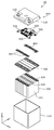
- FIG. 2 is an exploded perspective view showing each component when the power storage device according to the embodiment is disassembled.
- FIG. 3 is a perspective view showing the configuration of the power storage element according to the embodiment.
- FIG. 4 is a plan view showing an adhesive portion between the power storage element and the bus bar frame according to the embodiment.
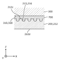
- FIG. 5 is an enlarged cross-sectional view showing a state in which the power storage element and the bus bar frame according to the embodiment are adhered to each other.
- FIG. 6 is a plan view showing an adhesive portion between the power storage element and the exterior body according to the embodiment.
- FIG. 7 is an enlarged cross-sectional view showing a state in which the power storage element and the exterior body according to the embodiment are adhered to each other.
- FIG. 8 is an enlarged cross-sectional view showing a state in which the power storage element and the exterior body according to the first modification of the embodiment are adhered to each other.
- FIG. 9 is an enlarged cross-sectional view showing a state in which the power storage element and the bus bar frame according to the second modification of the embodiment are adhered to each other.
- the movement of the power storage element in the power storage device can be suppressed.
- the adhesion between the power storage element and the adjacent member may be removed, and the power storage element may move in the power storage device. Therefore, a configuration that can further suppress the movement of the power storage element in the power storage device is desired.
- An object of the present invention is to provide a power storage device capable of suppressing the movement of a power storage element.
- the power storage device includes a power storage element, an adjacent member arranged adjacent to the power storage element, and an adhesive body for adhering the power storage element and the adjacent member.
- the adhesive surface has an adhesive surface that is adhered to the adjacent member by the adhesive body, and the adhesive surface has an uneven surface in which the uneven shape spreads in a plane shape.
- the power storage element has an adhesive surface that is adhered to an adjacent adjacent member by an adhesive body, and the adhesive surface has an uneven surface in which the uneven shape spreads in a plane shape. ..
- the adhesive area of the adhesive surface can be increased.
- the adhesive force between the power storage element and the adjacent member can be improved, so that the movement of the power storage element in the power storage device can be suppressed.
- the adhesive surface may have a surface adjacent to the adhesive surface or an uneven surface rougher than the surface on the back side of the adhesive surface.
- the adhesive surface of the power storage element with the adjacent member has an uneven surface that is coarser than the surface adjacent to the adhesive surface or the surface on the back side.
- the adhesive force on the uneven surface can be improved.
- the adhesive force between the power storage element and the adjacent member can be improved, so that the movement of the power storage element in the power storage device can be suppressed.
- the adhesive surface may have an uneven surface arranged on the bottom surface of the power storage element.
- the adhesive surface of the power storage element with the adjacent member has an uneven surface on the bottom surface of the power storage element. That is, since it is often possible to stably fix the power storage element in the power storage device by adhering the bottom surface of the power storage element to an adjacent member (exterior body or the like), an uneven surface is provided on the bottom surface of the power storage element. As a result, by improving the adhesive force between the bottom surface of the power storage element and the adjacent member (exterior body, etc.), the power storage element can be fixed more stably in the power storage device, so that the power storage element can be moved in the power storage device. Can be further suppressed.
- the adhesive surface may have an uneven surface arranged on the surface of the power storage element opposite to the electrode terminal.
- the adhesive surface of the power storage element with the adjacent member has an uneven surface on the side opposite to the electrode terminal. That is, on the electrode terminal side of the power storage element, the electrode terminal is connected to the bus bar and movement is restricted, but since the side opposite to the electrode terminal of the power storage element is easy to move, the side opposite to the electrode terminal of the power storage element An uneven surface is formed on the surface.
- the adhesive force between the surface on the side opposite to the electrode terminal of the power storage element and the adjacent member (exterior body, etc.) the movement on the side opposite to the electrode terminal of the power storage element can be suppressed. The movement of the power storage element in the device can be further suppressed.
- the surface of the power storage element on which the electrode terminals are arranged has an adhesive region that is adhered to the adjacent member and a non-adhesive region that is not adhered to the adjacent member, and the adhesive surface is arranged in the adhesive region. It may have an uneven surface that is rougher than the non-adhesive region.
- the adhesive surface of the power storage element with the adjacent member is arranged in the adhesive region of the surface of the power storage element on the electrode terminal side, and has a rough uneven surface that is rougher than the non-adhesive region. That is, when adhering an adjacent member (bus bar frame, etc.) to the surface of the power storage element on the electrode terminal side, the adjacent member is adhered to a part of the surface (adhesion region) so as to avoid the gas discharge valve and the electrode terminal. Will be done. Therefore, on the surface of the power storage element on the electrode terminal side, a concavo-convex surface having a concavo-convex shape that is coarser than the non-adhesive region is formed in the adhesive region. As a result, the adhesive force between the electrode terminal side surface of the power storage element and the adjacent member (bus bar frame or the like) can be improved, so that the movement of the power storage element in the power storage device can be suppressed.
- a power storage device includes a power storage element and an adjacent member arranged adjacent to the power storage element, and the power storage element is adhered to a bottom surface or an electrode.
- the adjacent member has a first adhesive surface that is a surface opposite to the terminal, and the adjacent member has a second adhesive surface that is adhered to the first adhesive surface, and the first adhesive surface and the second adhesive surface. At least one of the above may have an uneven surface in which the uneven shape spreads in a planar shape.
- the uneven shape spreads in a planar shape. It has an uneven surface.
- the adhesive area of the adhesive surface can be increased by forming an uneven surface in which the uneven shape spreads in a plane shape on at least one of the first adhesive surface of the power storage element and the second adhesive surface of the adjacent member. ..
- the adhesive force between the power storage element and the adjacent member can be improved.
- the power storage element can be fixed more stably in the power storage device.
- the adhesive force between the surface of the power storage element opposite to the electrode terminal and the adjacent member (exterior body, etc.) the movement of the power storage element on the opposite side of the electrode terminal is not restricted by the bus bar. Can be suppressed. As a result, the movement of the power storage element in the power storage device can be further suppressed.
- the direction in which the power storage elements are arranged or the direction opposite to the long side surface of the container of the power storage elements is defined as the X-axis direction.
- the direction in which the pair of (positive electrode side and negative electrode side) electrode terminals in one power storage element is arranged, or the direction in which the short side surfaces of the container of the power storage element face each other is defined as the Y-axis direction.
- the alignment direction of the outer body body and the lid of the power storage device, the arrangement direction of the container body and the lid of the power storage element, the arrangement direction of the power storage element and the bus bar frame, or the vertical direction is defined as the Z-axis direction.
- X-axis directions, Y-axis directions, and Z-axis directions intersect each other (orthogonally in the present embodiment).
- the Z-axis direction may not be the vertical direction, but for convenience of explanation, the Z-axis direction will be described below as the vertical direction.
- the X-axis plus direction indicates the arrow direction of the X-axis
- the X-axis minus direction indicates the direction opposite to the X-axis plus direction.
- Representations that indicate a relative direction or orientation, such as parallel and orthogonal also include cases that are not strictly that direction or orientation.
- the fact that the two directions are orthogonal not only means that the two directions are completely orthogonal, but also that they are substantially orthogonal, that is, that they include a difference of about several percent. Also means.
- FIG. 1 is a perspective view showing the appearance of the power storage device 10 according to the present embodiment.
- FIG. 2 is an exploded perspective view showing each component when the power storage device 10 according to the present embodiment is disassembled.
- the power storage device 10 is a device capable of charging electricity from the outside and discharging electricity to the outside, and has a substantially rectangular parallelepiped shape in the present embodiment.
- the power storage device 10 is a battery module (assembled battery) used for power storage or power supply.
- the power storage device 10 is used for driving a moving body such as an automobile, a motorcycle, a watercraft, a ship, a snowmobile, an agricultural machine, a construction machine, or a railroad vehicle for an electric railway, or for starting an engine. Used as a battery or the like.
- Examples of the above-mentioned automobiles include electric vehicles (EVs), hybrid electric vehicles (HEVs), plug-in hybrid electric vehicles (PHEVs), and gasoline vehicles.
- Examples of the above-mentioned railway vehicle for electric railways include trains, monorails, and linear motor cars.
- the power storage device 10 can also be used as a stationary battery or the like used for home use, a generator, or the like.
- the power storage device 10 includes an exterior body 100, and as shown in FIG. 2, a plurality of power storage elements 200, a bus bar frame 300, and a plurality of bus bars 400 are inside the exterior body 100. And 500, and electrical equipment 600 and the like are housed.
- the power storage device 10 may include a spacer or the like arranged between the plurality of power storage elements 200.
- the exterior body 100 is a box-shaped (substantially rectangular parallelepiped) container (module case) that constitutes the exterior body of the power storage device 10. That is, the exterior body 100 is arranged outside the plurality of power storage elements 200, the bus bar frame 300, the plurality of bus bars 400, 500, etc., and these power storage elements 200, etc. are fixed at predetermined positions to protect them from impacts and the like.
- the exterior body 100 includes polycarbonate (PC), polypropylene (PP), polyethylene (PE), polystyrene (PS), polyphenylene sulfide resin (PPS), polyphenylene ether (PPE (including modified PPE)), polyethylene terephthalate (PET).
- PC polycarbonate
- PP polypropylene
- PE polyethylene
- PS polystyrene
- PPS polyphenylene sulfide resin
- PPE polyphenylene ether
- PET polyethylene terephthalate
- the exterior body 100 prevents the power storage element 200 and the like from coming into contact with the external metal member and the like.
- the exterior body 100 may be formed of a conductive member such as metal as long as the electrical insulation of the power storage element 200 or the like is maintained.
- the exterior body 100 has an exterior body body 110 that constitutes the main body of the exterior body 100, and a lid body 120 that constitutes the lid body of the exterior body 100.
- the exterior body body 110 is a bottomed rectangular tubular housing (housing) having an opening, and accommodates a power storage element 200 and the like.
- the lid 120 is a flat rectangular member that is joined to the exterior body 110 by a heat seal or the like to close the opening of the exterior body 110.
- the lid 120 is provided with a positive electrode external terminal 121 and a negative electrode external terminal 122.
- the power storage device 10 charges electricity from the outside and discharges electricity to the outside via the positive electrode external terminal 121 and the negative electrode external terminal 122.
- the exterior body body 110 and the lid 120 may be made of members of the same material, or may be made of members of different materials.
- the exterior body 100 (exterior body main body 110) is an example of an adjacent member arranged adjacent to the power storage element 200.
- the power storage element 200 is a secondary battery (cell battery) capable of charging electricity and discharging electricity, and more specifically, a non-aqueous electrolyte secondary battery such as a lithium ion secondary battery.
- the power storage element 200 has a flat rectangular parallelepiped shape (square shape), and in the present embodiment, eight power storage elements 200 are arranged side by side in the X-axis direction. The shape of the power storage element 200 and the number of power storage elements 200 arranged are not limited.
- the power storage element 200 is not limited to the non-aqueous electrolyte secondary battery, and may be a secondary battery other than the non-aqueous electrolyte secondary battery, or may be a capacitor.
- the power storage element 200 may not be a secondary battery but a primary battery that can use the stored electricity without being charged by the user.
- the power storage element 200 may be a battery using a solid electrolyte.
- the power storage element 200 can also be a pouch-type power storage element.
- the power storage element 200 includes a container 210, a pair (positive electrode side and negative electrode side) of electrode terminals 220 (positive electrode terminal and negative electrode terminal), and the like. A detailed description of the configuration of these power storage elements 200 will be described later.
- the bus bar frame 300 is a rectangular and flat plate-shaped member that electrically insulates the bus bar 400 and the electric device 600 and the like from other members and regulates the positions of the bus bar 400 and the electric device 600 and the like. Specifically, the bus bar 400, the electric device 600, and the like are placed and positioned on the bus bar frame 300, and the bus bar frame 300 is placed on the plurality of power storage elements 200 and positioned with respect to the plurality of power storage elements 200. To. As a result, the bus bar 400 is positioned with respect to the plurality of power storage elements 200.
- the bus bar frame 300 is formed of an insulating material or the like similar to the material exemplified in the exterior body 100.
- the bus bar frame 300 is an example of an adjacent member arranged adjacent to the power storage element 200.
- the bus bars 400 and 500 are rectangular and flat plate-shaped members arranged above the plurality of power storage elements 200 and connected to the electrode terminals 220, the positive electrode external terminal 121, and the negative electrode external terminals 122 of the plurality of power storage elements 200. is there. That is, the bus bars 400 and 500 connect the electrode terminals 220 of the plurality of power storage elements 200 to each other, and also connect the electrode terminals 220 of the power storage element 200 at the ends to the positive electrode external terminal 121 and the negative electrode external terminal 122.
- the bus bars 400 and 500 are made of a conductive member made of metal such as aluminum, an aluminum alloy, copper or a copper alloy. In the present embodiment, the bus bar 400 connects two power storage elements 200 in parallel to form four sets of power storage element groups, and connects the four sets of power storage element groups in series. All eight power storage elements 200 may be connected in series, or other configurations may be used.
- the electric device 600 is an electric product mounted on the bus bar frame 300.
- the electric device 600 has a circuit board, a fuse, a relay, a shunt resistor, an electric component such as a connector, and the like for monitoring the charging state or the discharging state of the power storage element 200.
- the electric device 600 is connected to the bus bar 500 and is electrically connected to the power storage element 200, the positive electrode external terminal 121, the negative electrode external terminal 122, and the like.
- FIG. 3 is a perspective view showing the configuration of the power storage element 200 according to the present embodiment. Specifically, FIG. 3A is an enlarged perspective view of the power storage element 200 shown in FIG. 2, and FIG. 3B is an enlarged view of the power storage element 200 shown in FIG. 3A. It is a perspective view which shows the structure when seen from the lower side (Z-axis minus direction side).
- the power storage element 200 includes a container 210, a pair (positive electrode side and negative electrode side) of electrode terminals 220, and a pair (positive electrode side and negative electrode side) gasket 221.
- An electrode body, a pair of current collectors (positive electrode side and negative electrode side), an electrolytic solution (non-aqueous electrolyte), and the like are housed inside the container 210, but these are not shown.
- the type of the electrolytic solution is not particularly limited as long as it does not impair the performance of the power storage element 200, and various types can be selected.
- Gaskets are also arranged between the container 210 (the lid portion 212 described later) and the current collector, and spacers are arranged on the sides of the current collector, but these are not shown.
- the container 210 is a rectangular parallelepiped (square) container having a container main body 211 having an opening and a lid portion 212 for closing the opening of the container main body 211.
- the material of the container 210 (container body 211 and lid 212) is not particularly limited, but is preferably a weldable (bondable) metal such as stainless steel, aluminum, aluminum alloy, iron, and galvanized steel sheet.
- An insulating sheet 214 is arranged on the outer surface of the container body 211.
- the lid portion 212 is a rectangular plate-shaped member constituting the lid portion of the container 210, and is arranged on the Z-axis plus direction side of the container main body 211.
- the lid portion 212 is provided with a gas discharge valve 212a that releases the pressure inside the container 210 when the pressure rises, and a liquid injection portion 212b for injecting the electrolytic solution into the inside of the container 210.
- the lid portion 212 has a terminal arrangement surface 212c on which the electrode terminals 220 are arranged.
- the terminal arrangement surface 212c is a rectangular flat surface (outer surface or upper surface) arranged on the Z-axis plus direction side of the lid portion 212 and extending in the Y-axis direction.
- the terminal arrangement surface 212c of the lid portion 212 is formed with a first uneven surface 215 and a second uneven surface 216.
- the first uneven surface 215 is an uneven surface formed in a rectangular region between the electrode terminal 220 on the negative side of the Y-axis and the gas discharge valve 212a on the terminal arrangement surface 212c, and the uneven shape spreads in a plane shape. is there.
- the second uneven surface 216 is an uneven surface formed in a rectangular region between the electrode terminal 220 on the Y-axis positive direction side and the gas discharge valve 212a on the terminal arrangement surface 212c, and the uneven shape spreads in a plane shape. is there.
- the second uneven surface 216 is formed in a portion other than the liquid injection portion 212b in the region.
- a concavo-convex surface in which the concavo-convex shape spreads in a planar shape is formed in a portion other than the electrode terminal 220, the gas discharge valve 212a, and the liquid injection portion 212b.
- the second uneven surface 216 may also be formed on the surface of the liquid injection portion 212b.
- the above-mentioned uneven surface is a surface (for example, a pear ground) in which a rough uneven shape is spread out in a plane shape, which is coarser than other surfaces (a surface adjacent to the uneven surface or a surface on the back side of the uneven surface). That is, the uneven surface is a surface having a concave portion or a convex portion larger than the other surface even when the concave portion or the convex portion extending in a planar shape is formed on the other surface.
- the first concavo-convex surface 215 is an adjacent surface on both sides of the first concavo-convex surface 215 in the Y-axis direction, a surface adjacent to the terminal arrangement surface 212c (long side surface 211a, short side surface 211b of the container body 211, which will be described later), or It is a rougher surface than the back surface of the terminal arrangement surface 212c (the inner surface 212d of the lid portion in FIG. 5).
- Such an uneven surface can be formed by sandblasting, plasma, corona, etching, shot peening, press working, or the like. Whether or not the uneven surface is formed can be determined by observing the surface after removing the adhesive 700 described later, or by the difference in color from the portion where the uneven surface is not formed. it can. Whether or not the uneven surface is formed can be visually determined, for example.
- the roughness of the uneven surface (the size of the concave or convex portion) can be specified by the maximum height Rz.
- the maximum height Rz is a value obtained by extracting a part of the roughness curve with a reference length and adding the height value of the highest part and the depth value of the deepest part of the extracted part. ..
- the roughness of the uneven surface is preferably Rz of 0.05 z or more, more preferably Rz of 1.6 z or more, further preferably Rz of 12.5 z or more, and Rz of 12.5 z or more. It is more preferably 15z or more.
- the roughness of the uneven surface is preferably greater than or equal to the roughness formed by plasma treatment, and more preferably greater than or equal to the roughness formed by processing other than plasma treatment such as sandblasting.
- the roughness of the uneven surface is preferably Rz of 15 z or more. It is preferable that the uneven surface is formed with a concave portion having a shape in which the width becomes wider as the depth becomes deeper (or a convex portion having a shape in which the width becomes wider toward the tip) (see FIG. 5). ).
- the roughness of the uneven surface may be defined by an arithmetic mean roughness Ra or a numerical value expressing other roughness.
- the container main body 211 is a rectangular tubular member having a bottom that constitutes the main body portion of the container 210, has two long side surfaces 211a facing each other on both side surfaces in the X-axis direction, and is provided on both side surfaces in the Y-axis direction. It has two short side surfaces 211b facing each other and a bottom surface 211c on the negative side of the Z axis.
- the long side surface 211a is a rectangular flat surface forming the long side surface of the container 210. In other words, the long side surface 211a is a surface adjacent to the short side surface 211b, the bottom surface 211c and the terminal arrangement surface 212c, and has a larger area than the short side surface 211b.
- the short side surface 211b is a rectangular flat surface forming the short side surface of the container 210.
- the short side surface 211b is a surface adjacent to the long side surface 211a, the bottom surface 211c and the terminal arrangement surface 212c, and has a smaller area than the long side surface 211a.
- the bottom surface 211c is a rectangular flat surface forming the bottom surface of the container 210.
- the bottom surface 211c is a surface that faces the terminal arrangement surface 212c and is adjacent to the long side surface 211a and the short side surface 211b. That is, it can be said that the bottom surface 211c is the surface of the power storage element 200 opposite to the electrode terminal 220.
- the container body 211 has a curved container corner portion 211d at a boundary portion between the bottom surface 211c and the long side surface 211a and the short side surface 211b.
- a third uneven surface 217 is formed on the bottom surface 211c of the container body 211 and the container corner portion 211d.
- the third uneven surface 217 is an uneven surface in which the same uneven shape as the first uneven surface 215 and the second uneven surface 216 described above spreads in a planar shape. That is, for example, the third uneven surface 217 is a surface that is rougher than the surface adjacent to the bottom surface 211c (long side surface 211a, short side surface 211b) or the surface on the back side of the bottom surface 211c (bottom surface inner surface 211e in FIG. 7).
- the specific value of the roughness (the size of the concave or convex portion) of the uneven surface is the same as that of the first uneven surface 215 and the second uneven surface 216 described above.
- the third uneven surface 217 may not be formed on the container corner portion 211d, but is preferably formed on the container corner portion 211d from the viewpoint of improving the adhesive force.
- the insulating sheet 214 is an insulating sheet-like member that covers the outer surface of the container body 211.
- the material of the insulating sheet 214 is not particularly limited as long as it can secure the electrical insulating property required for the power storage element 200, but is the same insulating material as the material exemplified in the exterior body 100, or an epoxy resin, Kapton, or the like. Examples thereof include Teflon (registered trademark), silicon, polyisoprene, and polyvinyl chloride.
- the insulating sheet 214 is a single insulating sheet arranged so as to cover substantially the entire surface of the long side surface 211a and the short side surface 211b of the container body 211. In this way, the insulating sheet 214 is arranged on the outer surface of the container main body 211 with the terminal arrangement surface 212c and the bottom surface 211c exposed.
- a third uneven surface 217 is formed on the bottom surface 211c of the container main body 211 and the container corner portion 211d, and the first uneven surface 215 and the second uneven surface 216 are formed on the terminal arrangement surface 212c of the lid portion 212. Is formed. Then, an electrode body or the like is housed inside the container body 211, and the container body 211 and the lid portion 212 are joined by welding or the like to form the joint portion 213. That is, a joint portion 213 in which the container main body 211 and the lid portion 212 are joined to each other is formed on the side surfaces of the container 210 (both sides in the X-axis direction and both sides in the Y-axis direction).
- the electrolytic solution is injected into the container main body 211, the liquid injection portion 212b is closed, and the inside is sealed. Then, the long side surface 211a and the short side surface 211b of the container body 211 are covered with the insulating sheet 214.
- the electrode terminal 220 is a terminal (positive electrode terminal and negative electrode terminal) of the power storage element 200 arranged on the terminal arrangement surface 212c of the container 210, and is electrically connected to the positive electrode plate and the negative electrode plate of the electrode body via the current collector. It is connected. That is, the electrode terminal 220 is made of metal for leading the electricity stored in the electrode body to the external space of the power storage element 200 and introducing electricity into the internal space of the power storage element 200 in order to store the electricity in the electrode body. It is a member.
- the electrode terminal 220 is made of aluminum, an aluminum alloy, copper, a copper alloy, or the like.
- the gasket 221 is arranged around the electrode terminal 220 and between the electrode terminal 220 and the lid portion 212 of the container 210 to ensure electrical insulation and airtightness between the electrode terminal 220 and the container 210. It is a member of.
- the gasket 221 is formed of an insulating material or the like similar to the material exemplified in the exterior body 100.
- the electrode body is a power storage element (power generation element) formed by laminating a positive electrode plate, a negative electrode plate, and a separator.
- the positive electrode plate of the electrode body is formed by forming a positive electrode active material layer on a positive electrode base material layer which is a long strip-shaped current collecting foil made of a metal such as aluminum or an aluminum alloy.
- the negative electrode plate is formed by forming a negative electrode active material layer on a negative electrode base material layer which is a long strip-shaped current collecting foil made of a metal such as copper or a copper alloy.
- known materials can be appropriately used as long as they can occlude and release lithium ions.
- the current collector is a member (positive electrode current collector and negative electrode current collector) having conductivity and rigidity electrically connected to the electrode terminal 220 and the electrode body.
- the positive electrode current collector is formed of aluminum or an aluminum alloy or the like like the positive electrode base material layer of the positive electrode plate
- the negative electrode current collector is formed of copper or a copper alloy or the like like the negative electrode base material layer of the negative electrode plate.
- FIG. 4 is a plan view showing an adhesive portion between the power storage element 200 and the bus bar frame 300 according to the present embodiment.
- FIG. 4A is a top view showing a configuration when the plurality of power storage elements 200 shown in FIG. 2 are viewed from above (Z-axis plus direction side).
- FIG. 4B is a bottom view showing a configuration when the bus bar frame 300 is viewed from below (Z-axis minus direction side).
- FIG. 5 is an enlarged cross-sectional view showing a state in which the power storage element 200 and the bus bar frame 300 according to the present embodiment are adhered to each other.
- FIG. 6 is a plan view showing an adhesive portion between the power storage element 200 and the exterior body 100 according to the present embodiment.
- FIG. 6A is a bottom view showing a configuration when the plurality of power storage elements 200 shown in FIG. 2 are viewed from below (Z-axis minus direction side).
- FIG. 6B is a top view showing a configuration when the exterior body body 110 of the exterior body 100 is viewed from above (Z-axis plus direction side).
- FIG. 7 is an enlarged cross-sectional view showing a state in which the power storage element 200 and the exterior body 100 according to the present embodiment are adhered to each other.
- the terminal arrangement surface 212c which is the surface of the power storage element 200 on which the electrode terminals 220 are arranged, has an adhesive region 230 adhered to the bus bar frame 300 (adjacent member) and the bus bar frame 300 (adjacent member).
- the adhesive region 230 is an region on the terminal arrangement surface 212c where the first uneven surface 215 and the second uneven surface 216 are formed.
- the non-adhesive region 240 is a region on the terminal arrangement surface 212c where the first uneven surface 215 and the second uneven surface 216 are not formed.
- the non-adhesive region 240 is a region on the terminal arrangement surface 212c where the electrode terminals 220 and the gas discharge valve 212a are arranged. That is, the terminal arrangement surface 212c (adhesive surface) has a first uneven surface 215 and a second uneven surface 216, which are uneven surfaces that are rougher than the non-adhesive region 240 and are arranged in the adhesive region 230.
- the bus bar frame 300 has a flat adhesive surface 310 and a flat adhesive surface 320 at positions facing the first uneven surface 215 and the second uneven surface 216.
- the adhesive surface 310 faces one of the first uneven surface 215 and the second uneven surface 216
- the adhesive surface 320 faces the other of the first uneven surface 215 and the second uneven surface 216.
- the region where the adhesive surfaces 310 and 320 are formed is referred to as an adhesive region 330
- the region where the adhesive surfaces 310 and 320 are not formed is referred to as a non-adhesive region 340. That is, the adhesive region 230 of the power storage element 200 is arranged so as to face the adhesive region 330 of the bus bar frame 300 and is adhered to the adhesive region 330. In other words, the power storage element 200 is adhered to the adhesive surfaces 310 and 320 of the bus bar frame 300 on the first uneven surface 215 and the second uneven surface 216 of the terminal arrangement surface 212c.
- the bus bar frame 300 (adjacent member) is arranged adjacent to the power storage element 200 via the adhesive body 700, and is adhered to the power storage element 200 by the adhesive body 700. .. Specifically, the first uneven surface 215 or the second uneven surface 216 of the terminal arrangement surface 212c and the adhesive surface 310 or 320 of the bus bar frame 300 are adhered by the adhesive body 700. That is, the adhesive body 700 is applied to at least one of the first uneven surface 215 (or the second uneven surface 216) of the power storage element 200 and the adhesive surface 310 of the bus bar frame 300, and the first uneven surface 215 (or the second uneven surface 215) (or the second uneven surface). 216) and the adhesive surface 310 are adhered.
- the first concavo-convex surface 215 and the second concavo-convex surface 216 are concave portions having a shape in which the width becomes wider as the depth becomes deeper (or convex portions having a shape in which the width becomes wider toward the tip). ), And the adhesive body 700 enters the recess to generate an anchor effect.
- the adhesive body 700 is an adhesive that adheres the power storage element 200 and the bus bar frame 300 (adjacent member).
- a resin adhesive or the like which is in a liquid state before bonding and which is solidified to bond can be used.
- a gel-like adhesive or a solid adhesive such as a hot melt adhesive can be used before bonding.
- the exterior body body 110 of the exterior body 100 has a flat adhesive surface 112 (also referred to as a second adhesive surface) at a position facing the third uneven surface 217 of the bottom surface 211c of the power storage element 200.
- the exterior body body 110 has a plurality of ribs 111 extending in the X-axis direction on the bottom surface, and the adhesive surface 112 is arranged at a position sandwiching the ribs 111. Then, the third uneven surface 217 of the bottom surface 211c of the power storage element 200 and the adhesive surface 112 of the exterior body 110 are adhered to each other.
- the bottom surface 211c of the power storage element 200 is an adhesive surface (also referred to as a first adhesive surface) to be adhered to the exterior body 100 (adjacent member).
- the adhesive surface 112 is provided on the bottom surface of the exterior body body 110, but it does not necessarily have to be provided on the rib 111 arranged on the bottom surface. That is, the adhesive body 700, which will be described later, is provided between the adhesive surface 112 on the bottom surface of the exterior body 110 and the bottom surface 211c of the power storage element 200, but is provided between the rib 111 and the bottom surface 211c of the power storage element 200. It does not have to be. According to this aspect, by adjusting the height of the rib 111 to the optimum thickness at which the adhesive 700 can maximize the adhesive force, the thickness of the adhesive 700 can be obtained by simply pressing the power storage element 200 toward the rib 111. Can be optimally managed.
- the adhesive body 700 When the adhesive body 700 is liquid before being cured, it is possible to apply the adhesive body 700 not only on the adhesive surface 112 but also on the rib 111, and the above-mentioned method of pressing the power storage element 200 toward the rib 111. Therefore, the adhesive body 700 can be removed from the rib 111.
- the exterior body 100 is arranged adjacent to the power storage element 200 via the adhesive body 700, similarly to the bus bar frame 300, and is adhered to the power storage element 200 by the adhesive body 700. Will be done.
- the third uneven surface 217 of the bottom surface 211c of the power storage element 200 and the adhesive surface 112 of the exterior body 110 are adhered by the adhesive body 700. That is, the adhesive body 700 is applied to at least one of the third uneven surface 217 and the adhesive surface 112, and the third uneven surface 217 and the adhesive surface 112 are adhered to each other.
- the adhesive body 700 is applied to the bottom surface 211c with the bottom surface 211c of the power storage element 200 facing upward, and the exterior body 110 is put on the power storage element 200 to adhere the third uneven surface 217 to the bottom surface 211c.
- the same adhesive as the adhesive for adhering the power storage element 200 and the bus bar frame 300 can be used.
- the third uneven surface 217 has the same shape as the first uneven surface 215 and the second uneven surface 216, and has a configuration in which an anchor effect is generated.
- the container corner portion 211d of the power storage element 200 also has a third uneven surface 217 formed and adhered to the adhesive surface 112 of the exterior body body 110 in the same manner as the bottom surface 211c. Since it is the same as the bottom surface 211c, the description thereof will be omitted.
- the power storage element 200 has an adhesive surface (terminal) bonded to the adjacent adjacent members (bus bar frame 300, exterior body 100) by the adhesive body 700. It has an arrangement surface 212c and a bottom surface 211c).
- the adhesive surface has an uneven surface (first uneven surface 215, second uneven surface 216, third uneven surface 217) in which the uneven shape spreads in a planar shape. In this way, by forming a concavo-convex surface in which the concavo-convex shape spreads in a planar shape on the adhesive surface of the power storage element 200 with the adjacent member, the adhesive area of the adhesive surface can be increased.
- the adhesive force between the power storage element 200 and the adjacent member can be improved, so that the movement of the power storage element 200 in the power storage device 10 can be suppressed.
- an anchor effect can be generated, so that the adhesive force between the power storage element 200 and the adjacent member can be further improved.
- the movement of the power storage element 200 in the power storage device 10 can be further suppressed.
- the surface of the container 210 of the power storage element 200 may be subjected to plasma treatment to improve the adhesive force with the adjacent member.
- plasma treatment when plasma treatment is applied to the surface of the container 210, there is also a problem that the effect of plasma treatment varies. Therefore, the inventor of the present application has found that it is effective to form an uneven surface in which the uneven shape spreads in a plane shape on the adhesive surface in order to reduce the variation in the adhesive force.
- the simple operation of forming the uneven surface on the adhesive surface can suppress the variation in the adhesive force between the power storage element 200 and the adjacent member, so that the movement of the power storage element 200 in the power storage device 10 can be suppressed.
- the adhesive surface of the power storage element 200 with the adjacent member has an uneven surface that is coarser than the surface adjacent to the adhesive surface or the surface on the back side. In this way, by making the uneven surface on the adhesive surface of the power storage element 200 rougher than the other surface (adjacent surface or back surface), the adhesive force on the uneven surface can be improved. As a result, the adhesive force between the power storage element 200 and the adjacent member can be improved, so that the movement of the power storage element 200 in the power storage device 10 can be suppressed.
- the adhesive surface of the power storage element 200 with the exterior body 100 has a third uneven surface 217 which is an uneven surface of the bottom surface 211c of the power storage element 200. That is, in many cases, the power storage element 200 can be stably fixed in the power storage device 10 by adhering the bottom surface 211c of the power storage element 200 to the exterior body 100, so that the third uneven surface 217 is provided on the bottom surface 211c of the power storage element 200. Provide. As a result, the power storage element 200 can be more stably fixed in the power storage device 10 by improving the adhesive force between the bottom surface 211c of the power storage element 200 and the exterior body 100. Therefore, the power storage element 200 in the power storage device 10 The movement of the can be further suppressed.
- the adhesive surface of the power storage element 200 with the exterior body 100 has a third uneven surface 217 which is an uneven surface on the side opposite to the electrode terminal 220. That is, on the electrode terminal 220 side of the power storage element 200, the electrode terminal 220 is connected to the bus bar 400 and movement is restricted, but the side opposite to the electrode terminal 220 of the power storage element 200 is easy to move, so that the power storage element 200 A third uneven surface 217 is formed on the surface opposite to the electrode terminal 220.
- the adhesive force between the surface of the power storage element 200 opposite to the electrode terminal 220 and the exterior body 100 the movement of the power storage element 200 on the side opposite to the electrode terminal 220 can be suppressed.
- the movement of the power storage element 200 in the device 10 can be further suppressed.
- the adhesive surface of the power storage element 200 with the bus bar frame 300 is arranged in the adhesive region 230 of the terminal arrangement surface 212c, which is the surface of the power storage element 200 on the electrode terminal 220 side, and is a rough surface that is rougher than the non-adhesive region 240. It has an uneven surface 215 and a second uneven surface 216. That is, when the bus bar frame 300 is adhered to the terminal arrangement surface 212c of the power storage element 200, the bus bar frame 300 is adhered to a part of the surfaces (adhesion region 230) so as to avoid the gas discharge valve 212a and the electrode terminals 220. Will be done.
- the first uneven surface 215 and the second uneven surface 216 having a rougher uneven shape than the non-adhesive region 240 are formed in the adhesive region 230.
- the adhesive force between the terminal arrangement surface 212c of the power storage element 200 and the bus bar frame 300 can be improved, so that the movement of the power storage element 200 in the power storage device 10 can be suppressed.
- FIG. 8 is an enlarged cross-sectional view showing a state in which the power storage element 200 and the exterior body 100 according to the first modification of the present embodiment are adhered to each other. Specifically, FIG. 8 is a diagram corresponding to FIG. 7.
- the power storage element 200 does not have the third uneven surface 217 on the bottom surface 211c of the container body 211, and the exterior body 100 is the exterior body.
- the adhesive surface 112 of the main body 110 has an uneven surface 113. Since other configurations are the same as those in the above embodiment, detailed description thereof will be omitted.
- the uneven surface 113 has the same shape as the first uneven surface 215, the second uneven surface 216, and the third uneven surface 217 described above.
- the exterior body 100 adjacent member
- the uneven surface 113 can be formed, for example, by the same method as forming the uneven surface on the power storage element 200 described above, or by applying a graining process to the adhesive surface 112 of the exterior body body 110.
- the third uneven surface 217 may be formed on the bottom surface 211c (first adhesive surface) of the power storage element 200 as in the above embodiment. That is, at least one of the first adhesive surface and the second adhesive surface may have an uneven surface in which the uneven shape spreads in a planar shape. From the viewpoint of improving the adhesive force, it is preferable that both the first adhesive surface and the second adhesive surface have an uneven surface.
- the same effect as that of the above embodiment can be obtained.
- at least one of the first adhesive surface, which is the surface opposite to the bottom surface 211c of the power storage element 200 or the electrode terminal 220, and the second adhesive surface of the exterior body 100 (adjacent member) is uneven. It has an uneven surface whose shape spreads like a surface.
- the power storage element 200 can be fixed more stably in the power storage device 10.
- the adhesive force between the surface of the power storage element 200 opposite to the electrode terminal 220 and the exterior body 100 By improving the adhesive force between the surface of the power storage element 200 opposite to the electrode terminal 220 and the exterior body 100, the movement of the power storage element 200 opposite to the electrode terminal 220 is not restricted by the bus bar 400. Can also be suppressed. As a result, the movement of the power storage element 200 in the power storage device 10 can be further suppressed. Since the anchor effect can be generated by forming the uneven surface on the adhesive surface, the adhesive force between the power storage element 200 and the exterior body 100 can be further improved, and the power storage element 200 in the power storage device 10 can be further improved. Movement can be further suppressed.
- This modification can be applied not only to the adhesive surface 112 of the exterior body 100 but also to the adhesive surfaces 310 and 320 of the bus bar frame 300. That is, an uneven surface may be formed on at least one of the adhesive surfaces 310 and 320 of the bus bar frame 300.
- the terminal arrangement surface 212c of the power storage element 200 may be formed with the first uneven surface 215 and the second uneven surface 216, or at least one of the first uneven surface 215 and the second uneven surface 216 is formed. It does not have to be. That is, at least one of the terminal arrangement surface 212c of the power storage element 200 and the adhesive surfaces 310 and 320 of the bus bar frame 300 may have an uneven surface in which the uneven shape spreads in a plane shape.
- FIG. 9 is an enlarged cross-sectional view showing a state in which the power storage element 200 and the bus bar frame 300 according to the second modification of the present embodiment are adhered to each other. Specifically, FIG. 9 is a diagram corresponding to FIG.
- the power storage element 200 has a third uneven surface 218 on the terminal arrangement surface 212c of the lid portion 212. Since other configurations are the same as those in the above embodiment, detailed description thereof will be omitted.
- the third uneven surface 218 has a concave portion having a triangular cross section in the XZ plane.
- the shape of the concave portion (or convex portion) of the third concave-convex surface 218 does not have to be the triangular shape, and any shape such as a rectangular shape, other polygonal shape, semicircular shape, semicircular shape, semi-elliptical shape, etc. It may be in shape.
- the shape of the concave portion or the convex portion formed on the uneven surface is not particularly limited, and the concave portion or the convex portion having any shape may be formed.
- the same effect as that of the above embodiment can be obtained.
- the shape of the concave portion (or convex portion) of the third uneven surface 218 is not limited, the third uneven surface 218 can be easily formed on the terminal arrangement surface 212c of the power storage element 200.
- This modification can be applied to all uneven surfaces provided on the adhesive surface other than the terminal arrangement surface 212c of the power storage element 200.
- the exterior body 100 (exterior body main body 110) and the bus bar frame 300 have been exemplified as examples of the adjacent members arranged adjacent to the power storage element 200, but the present invention is not limited thereto.
- the adjacent member an insulating member arranged adjacent to the power storage element 200, such as an intermediate spacer placed between the two power storage elements 200 or an end spacer placed adjacent to the power storage element 200 at the end.
- various members can be exemplified.
- the adjacent member is a concept that includes a member such as the insulating member (resin member) as an example, and does not include another power storage element 200 arranged adjacent to the power storage element 200 as an example.
- the power storage device is a non-restraint type power storage device in which a plurality of power storage elements 200 are not restrained by restraint members (side plates, end plates, etc.).
- it may be a restraint type power storage device that restrains a plurality of power storage elements 200 with the restraint member.
- the restraining member (side plate, end plate, etc.) may be adhered to the power storage element 200 as an example of the adjacent member.
- the non-restraint type power storage device wants to suppress the movement of the power storage element 200, the effect of applying the present application is high.
- At least one of the short side surface 211b of the container body 211 of the power storage element 200 and the adjacent member adjacent to the short side surface 211b may have an uneven surface in which the uneven shape spreads in a planar shape.
- the power storage element 200 does not have to have the insulating sheet 214.
- the uneven surface may be formed on the insulating sheet 214 instead of forming the uneven surface on the container body 211.
- the uneven surfaces such as the first uneven surface 215, the second uneven surface 216, and the third uneven surface 217, 218 are surfaces adjacent to the uneven surface or the back side of the uneven surface. It was decided that it was rougher than the surface of. However, the uneven surface may be rougher than a surface different from the adjacent surface and the back surface. The uneven surface may have the same roughness as the other surface or may not be rougher than the other surface as long as the adhesive area is large or the roughness can cause the anchor effect.
- the surface (bottom surface 211c) of the power storage element 200 opposite to the electrode terminal 220 is assumed to be the bottom surface of the power storage element 200.
- the long side surface 211a, the short side surface 211b, or the terminal arrangement surface 212c becomes the bottom surface of the power storage element 200.
- any of the power storage elements 200 does not have to have the above configuration.
- Either the terminal arrangement surface 212c side or the bottom surface 211c side of the power storage element 200 may not have the above configuration.
- the scope of the present invention also includes a form constructed by arbitrarily combining the above-described embodiments and the components included in the modified examples.
- the present invention can be realized not only as such a power storage device, but also as a power storage element 200 having an adhesive surface (first adhesive surface) or an adjacent member (exterior body 100, bus bar frame 300, etc.) having a second adhesive surface. Can also be realized.
- the present invention can be applied to a power storage device or the like equipped with a power storage element such as a lithium ion secondary battery.
- Power storage device 100 Exterior body 110 Exterior body body 112, 310, 320 Adhesive surface 113 Concavo-convex surface 200 Power storage element 210 Container 211 Container body 211a Long side surface 211b Short side surface 211c Bottom surface 211d Container corner part 211e Bottom surface inner surface 212 Lid part 212a Gas discharge valve 212b Liquid injection part 212c Terminal arrangement surface 212d Lid inner surface 215 First uneven surface 216 Second uneven surface 217, 218 Third uneven surface 220 Electrode terminals 230, 330 Adhesive area 240, 340 Non-adhesive area 300 Bus bar frame 700 Adhesive
Landscapes
- Chemical & Material Sciences (AREA)
- Chemical Kinetics & Catalysis (AREA)
- Electrochemistry (AREA)
- General Chemical & Material Sciences (AREA)
- Engineering & Computer Science (AREA)
- Power Engineering (AREA)
- Aviation & Aerospace Engineering (AREA)
- Microelectronics & Electronic Packaging (AREA)
- Connection Of Batteries Or Terminals (AREA)
- Battery Mounting, Suspending (AREA)
Abstract
蓄電装置(10)は、蓄電素子(200)と、蓄電素子(200)に隣接して配置される隣接部材(バスバーフレーム(300)、外装体(100))と、蓄電素子(200)及び隣接部材を接着する接着体(700)と、を備え、蓄電素子(200)は、接着体(700)によって隣接部材と接着される接着面(端子配置面(212c)、底面(211c))を有し、接着面は、凹凸形状が面状に広がる凹凸面(第一凹凸面(215)、第二凹凸面(216)、第三凹凸面(217))を有する。
Description
本発明は、蓄電素子を備える蓄電装置に関する。
従来、蓄電素子と、蓄電素子に隣接して配置される隣接部材と、を備え、蓄電素子と隣接部材とが接着される構成の蓄電装置が知られている。特許文献1には、複数の電池セル(蓄電素子)と、電池セルを保持する保持体(隣接部材)と、を備え、電池セルと保持体とが接着された組電池(蓄電装置)が開示されている。
蓄電装置において、蓄電装置内での蓄電素子の移動をより抑制できる構成が望まれる。
本発明は、蓄電素子の移動を抑制できる蓄電装置を提供することを目的とする。
本発明の一態様に係る蓄電装置は、蓄電素子と、前記蓄電素子に隣接して配置される隣接部材と、前記蓄電素子及び前記隣接部材を接着する接着体と、を備え、前記蓄電素子は、前記接着体によって前記隣接部材と接着される接着面を有し、前記接着面は、凹凸形状が面状に広がる凹凸面を有する。
本発明は、このような蓄電装置として実現できるだけでなく、接着面(第一接着面)を有する蓄電素子、または、第二接着面を有する隣接部材としても実現できる。
本発明における蓄電装置によれば、蓄電素子の移動を抑制できる。
上記従来の蓄電装置のように、蓄電素子を隣接部材に接着して隣接部材に固定することで、蓄電装置内での蓄電素子の移動を抑制できる。しかしながら、外部から大きな振動または衝撃が加えられた場合等に、蓄電素子と隣接部材との接着が外れて、蓄電装置内で蓄電素子が移動してしまうおそれがある。このため、蓄電装置内での蓄電素子の移動をより抑制できる構成が望まれる。
本発明は、蓄電素子の移動を抑制できる蓄電装置を提供することを目的とする。
本発明の一態様に係る蓄電装置は、蓄電素子と、前記蓄電素子に隣接して配置される隣接部材と、前記蓄電素子及び前記隣接部材を接着する接着体と、を備え、前記蓄電素子は、前記接着体によって前記隣接部材と接着される接着面を有し、前記接着面は、凹凸形状が面状に広がる凹凸面を有する。
これによれば、蓄電装置において、蓄電素子は、隣接する隣接部材と接着体によって接着される接着面を有しており、接着面は、凹凸形状が面状に広がる凹凸面を有している。このように、蓄電素子の隣接部材との接着面に、凹凸形状が面状に広がる凹凸面を形成することで、当該接着面の接着面積を増加させることができる。これにより、蓄電素子と隣接部材との接着力の向上を図ることができるため、蓄電装置内での蓄電素子の移動を抑制できる。
前記接着面は、前記接着面に隣り合う面、または、前記接着面の裏側の面よりも粗い凹凸面を有してもよい。
これによれば、蓄電素子の隣接部材との接着面は、当該接着面に隣り合う面または裏側の面よりも粗い凹凸面を有している。このように、蓄電素子の接着面における凹凸面を、他の面(隣り合う面または裏側の面)よりも粗くすることで、凹凸面での接着力を向上できる。これにより、蓄電素子と隣接部材との接着力の向上を図ることができるため、蓄電装置内での蓄電素子の移動を抑制できる。
前記接着面は、前記蓄電素子の底面に配置される凹凸面を有してもよい。
これによれば、蓄電素子の隣接部材との接着面は、蓄電素子の底面の凹凸面を有している。つまり、蓄電素子の底面を隣接部材(外装体等)に接着することで、蓄電装置内で蓄電素子を安定的に固定できる場合が多いため、蓄電素子の底面に凹凸面を設ける。これにより、蓄電素子の底面と隣接部材(外装体等)との接着力の向上を図ることで、蓄電装置内で蓄電素子をより安定的に固定できるため、蓄電装置内での蓄電素子の移動をより抑制できる。
前記接着面は、前記蓄電素子における電極端子とは反対側の面に配置される凹凸面を有してもよい。
これによれば、蓄電素子の隣接部材との接着面は、電極端子とは反対側の面の凹凸面を有している。つまり、蓄電素子の電極端子側は、電極端子がバスバーに接続されて動きが拘束されるが、蓄電素子の電極端子とは反対側は、動きやすいため、蓄電素子の電極端子とは反対側の面に凹凸面を形成する。これにより、蓄電素子の電極端子とは反対側の面と隣接部材(外装体等)との接着力の向上を図ることで、蓄電素子の電極端子とは反対側の動きも抑制できるため、蓄電装置内での蓄電素子の移動をより抑制できる。
前記蓄電素子における電極端子が配置されている面は、前記隣接部材に接着される接着領域と、前記隣接部材に接着されない非接着領域と、を有し、前記接着面は、前記接着領域に配置される、前記非接着領域よりも粗い凹凸面を有してもよい。
これによれば、蓄電素子の隣接部材との接着面は、蓄電素子の電極端子側の面の接着領域に配置され、非接着領域よりも粗い凹凸面を有している。つまり、蓄電素子の電極端子側の面に隣接部材(バスバーフレーム等)を接着する場合には、ガス排出弁及び電極端子等を避けるように、一部の面(接着領域)に隣接部材を接着することとなる。このため、蓄電素子の電極端子側の面において、接着領域に、非接着領域よりも粗い凹凸形状の凹凸面を形成する。これにより、蓄電素子の電極端子側の面と隣接部材(バスバーフレーム等)との接着力の向上を図ることができるため、蓄電装置内での蓄電素子の移動を抑制できる。
本発明の他の一態様に係る蓄電装置は、蓄電素子と、前記蓄電素子に隣接して配置される隣接部材と、を備え、前記蓄電素子は、前記隣接部材と接着される、底面または電極端子とは反対側の面である第一接着面を有し、前記隣接部材は、前記第一接着面と接着される第二接着面を有し、前記第一接着面及び前記第二接着面の少なくとも一方は、凹凸形状が面状に広がる凹凸面を有してもよい。
これによれば、蓄電装置において、蓄電素子の底面または電極端子とは反対側の面である第一接着面、及び、隣接部材の第二接着面の少なくとも一方は、凹凸形状が面状に広がる凹凸面を有している。このように、蓄電素子の第一接着面及び隣接部材の第二接着面の少なくとも一方に、凹凸形状が面状に広がる凹凸面を形成することで、接着面の接着面積を増加させることができる。これにより、蓄電素子と隣接部材との接着力の向上を図ることができる。特に、蓄電素子の底面と隣接部材(外装体等)との接着力の向上を図ることで、蓄電装置内で蓄電素子をより安定的に固定できる。蓄電素子の電極端子とは反対側の面と隣接部材(外装体等)との接着力の向上を図ることで、バスバーで動きが拘束されていない蓄電素子の電極端子とは反対側の動きも抑制できる。これらにより、蓄電装置内での蓄電素子の移動をより抑制できる。
以下、図面を参照しながら、本発明の実施の形態(その変形例も含む)に係る蓄電装置について説明する。以下で説明する実施の形態は、いずれも包括的または具体的な例を示すものである。以下の実施の形態で示される数値、形状、材料、構成要素、構成要素の配置位置及び接続形態、製造工程、製造工程の順序等は、一例であり、本発明を限定する主旨ではない。各図において、寸法等は厳密に図示したものではない。
以下の説明及び図面中において、蓄電素子の並び方向、または、蓄電素子の容器の長側面の対向方向を、X軸方向と定義する。1つの蓄電素子における一対(正極側及び負極側)の電極端子の並び方向、または、蓄電素子の容器の短側面の対向方向を、Y軸方向と定義する。蓄電装置の外装体本体と蓋体との並び方向、蓄電素子の容器本体と蓋部との並び方向、蓄電素子とバスバーフレームとの並び方向、または、上下方向を、Z軸方向と定義する。これらX軸方向、Y軸方向及びZ軸方向は、互いに交差(本実施の形態では直交)する方向である。使用態様によってはZ軸方向が上下方向にならない場合も考えられるが、以下では説明の便宜のため、Z軸方向を上下方向として説明する。
以下の説明において、X軸プラス方向とは、X軸の矢印方向を示し、X軸マイナス方向とは、X軸プラス方向とは反対方向を示す。Y軸方向及びZ軸方向についても同様である。平行及び直交などの、相対的な方向または姿勢を示す表現は、厳密には、その方向または姿勢ではない場合も含む。2つの方向が直交している、とは、当該2つの方向が完全に直交していることを意味するだけでなく、実質的に直交していること、すなわち、数%程度の差異を含むことも意味する。
(実施の形態)
[1 蓄電装置10の全般的な説明]
まず、本実施の形態における蓄電装置10の全般的な説明を行う。図1は、本実施の形態に係る蓄電装置10の外観を示す斜視図である。図2は、本実施の形態に係る蓄電装置10を分解した場合の各構成要素を示す分解斜視図である。
[1 蓄電装置10の全般的な説明]
まず、本実施の形態における蓄電装置10の全般的な説明を行う。図1は、本実施の形態に係る蓄電装置10の外観を示す斜視図である。図2は、本実施の形態に係る蓄電装置10を分解した場合の各構成要素を示す分解斜視図である。
蓄電装置10は、外部からの電気を充電し、また外部へ電気を放電できる装置であり、本実施の形態では、略直方体形状を有している。蓄電装置10は、電力貯蔵用途または電源用途等に使用される電池モジュール(組電池)である。具体的には、蓄電装置10は、自動車、自動二輪車、ウォータークラフト、船舶、スノーモービル、農業機械、建設機械、または、電気鉄道用の鉄道車両等の移動体の駆動用またはエンジン始動用等のバッテリ等として用いられる。上記の自動車としては、電気自動車(EV)、ハイブリッド電気自動車(HEV)、プラグインハイブリッド電気自動車(PHEV)及びガソリン自動車が例示される。上記の電気鉄道用の鉄道車両としては、電車、モノレール及びリニアモーターカーが例示される。蓄電装置10は、家庭用または発電機用等に使用される定置用のバッテリ等としても用いることができる。
図1に示すように、蓄電装置10は、外装体100を備えており、図2に示すように、外装体100の内方には、複数の蓄電素子200、バスバーフレーム300、複数のバスバー400及び500、並びに、電気機器600等が収容されている。蓄電装置10は、複数の蓄電素子200の間に配置されるスペーサ等を備えていてもよい。
外装体100は、蓄電装置10の外装体を構成する箱形(略直方体形状)の容器(モジュールケース)である。つまり、外装体100は、複数の蓄電素子200、バスバーフレーム300及び複数のバスバー400、500等の外方に配置され、これら蓄電素子200等を所定の位置で固定し、衝撃等から保護する。外装体100は、ポリカーボネート(PC)、ポリプロピレン(PP)、ポリエチレン(PE)、ポリスチレン(PS)、ポリフェニレンサルファイド樹脂(PPS)、ポリフェニレンエーテル(PPE(変性PPEを含む))、ポリエチレンテレフタラート(PET)、ポリブチレンテレフタレート(PBT)、ポリエーテルエーテルケトン(PEEK)、テトラフルオロエチレン・パーフルオロアルキルビニルエーテル(PFA)、ポリテトラフルオロエチレン(PTFE)、ポリエーテルサルフォン(PES)、ABS樹脂、若しくは、それらの複合材料等の絶縁部材、または、絶縁塗装をした金属等により形成されている。外装体100は、これにより、蓄電素子200等が外部の金属部材等に接触することを回避する。蓄電素子200等の電気的絶縁性が保たれる構成であれば、外装体100は、金属等の導電部材で形成されていてもよい。
外装体100は、外装体100の本体を構成する外装体本体110と、外装体100の蓋体を構成する蓋体120と、を有している。外装体本体110は、開口が形成された有底矩形筒状のハウジング(筐体)であり、蓄電素子200等を収容する。蓋体120は、外装体本体110とヒートシール等によって接合されて、外装体本体110の開口を閉塞する扁平な矩形状の部材である。蓋体120には、正極外部端子121と負極外部端子122とが設けられている。蓄電装置10は、この正極外部端子121と負極外部端子122とを介して、外部からの電気を充電し、また外部へ電気を放電する。外装体本体110及び蓋体120は、同じ材質の部材で形成されていてもよいし、異なる材質の部材で形成されていてもよい。外装体100(外装体本体110)は、蓄電素子200に隣接して配置される隣接部材の一例である。
蓄電素子200は、電気を充電し、電気を放電することのできる二次電池(単電池)であり、より具体的には、リチウムイオン二次電池等の非水電解質二次電池である。蓄電素子200は、扁平な直方体形状(角形)の形状を有しており、本実施の形態では、8個の蓄電素子200がX軸方向に並んで配列されている。蓄電素子200の形状、及び、配列される蓄電素子200の個数は限定されない。蓄電素子200は、非水電解質二次電池には限定されず、非水電解質二次電池以外の二次電池であってもよいし、キャパシタであってもよい。蓄電素子200は、二次電池ではなく、使用者が充電をしなくても蓄えられている電気を使用できる一次電池であってもよい。蓄電素子200は、固体電解質を用いた電池であってもよい。蓄電素子200は、パウチタイプの蓄電素子とすることもできる。
具体的には、蓄電素子200は、容器210、及び、一対(正極側及び負極側)の電極端子220(正極端子及び負極端子)等を備えている。これら蓄電素子200の構成の詳細な説明については、後述する。
バスバーフレーム300は、バスバー400及び電気機器600等と他の部材との電気的な絶縁、並びに、バスバー400及び電気機器600等の位置規制を行う矩形状かつ平板状の部材である。具体的には、バスバーフレーム300上にバスバー400及び電気機器600等が載置されて位置決めされ、複数の蓄電素子200上にバスバーフレーム300が載置されて複数の蓄電素子200に対して位置決めされる。これにより、バスバー400が、複数の蓄電素子200に対して位置決めされる。バスバーフレーム300は、外装体100で例示した材料と同様の絶縁材料等により形成されている。バスバーフレーム300は、蓄電素子200に隣接して配置される隣接部材の一例である。
バスバー400及び500は、複数の蓄電素子200の上方に配置され、複数の蓄電素子200の電極端子220、正極外部端子121、及び、負極外部端子122に接続される矩形状かつ平板状の部材である。つまり、バスバー400及び500は、複数の蓄電素子200の電極端子220同士を接続し、かつ、端部の蓄電素子200の電極端子220と正極外部端子121及び負極外部端子122とを接続する。バスバー400及び500は、アルミニウム、アルミニウム合金、銅または銅合金等の金属製の導電部材等で形成されている。本実施の形態では、バスバー400は、蓄電素子200を2個ずつ並列に接続して4セットの蓄電素子群を構成し、当該4セットの蓄電素子群を直列に接続するが、バスバー400は、8個の蓄電素子200を全て直列に接続してもよいし、その他の構成であってもかまわない。
電気機器600は、バスバーフレーム300に載置される電気品である。電気機器600は、蓄電素子200の充電状態または放電状態を監視するための回路基板、ヒューズ、リレー、シャント抵抗、コネクタ等の電気部品等を有している。電気機器600は、バスバー500に接続されて、蓄電素子200、正極外部端子121、負極外部端子122等と電気的に接続される。
[2 蓄電素子200の構成の説明]
次に、蓄電素子200の構成について、詳細に説明する。図2に示した複数(8個)の蓄電素子200の全てが同様の構成を有するため、以下では、1つの蓄電素子200の構成について説明する。図3は、本実施の形態に係る蓄電素子200の構成を示す斜視図である。具体的には、図3の(a)は、図2に示した蓄電素子200を拡大して示す斜視図であり、図3の(b)は、図3の(a)の蓄電素子200を下方(Z軸マイナス方向側)から見た場合の構成を示す斜視図である。
次に、蓄電素子200の構成について、詳細に説明する。図2に示した複数(8個)の蓄電素子200の全てが同様の構成を有するため、以下では、1つの蓄電素子200の構成について説明する。図3は、本実施の形態に係る蓄電素子200の構成を示す斜視図である。具体的には、図3の(a)は、図2に示した蓄電素子200を拡大して示す斜視図であり、図3の(b)は、図3の(a)の蓄電素子200を下方(Z軸マイナス方向側)から見た場合の構成を示す斜視図である。
図3に示すように、蓄電素子200は、容器210と、一対(正極側及び負極側)の電極端子220と、一対(正極側及び負極側)のガスケット221と、を備えている。容器210の内方には、電極体、一対(正極側及び負極側)の集電体、及び電解液(非水電解質)等が収容されているが、これらの図示は省略する。当該電解液としては、蓄電素子200の性能を損なうものでなければその種類に特に制限はなく、様々なものを選択できる。容器210(後述の蓋部212)と集電体との間にもガスケットが配置され、集電体の側方等にはスペーサが配置されているが、これらの図示も省略する。
容器210は、開口が形成された容器本体211と、容器本体211の開口を閉塞する蓋部212とを有する直方体形状(角形)の容器である。容器210(容器本体211及び蓋部212)の材質は、特に限定されないが、ステンレス鋼、アルミニウム、アルミニウム合金、鉄、メッキ鋼板など溶接可能(接合可能)な金属であるのが好ましい。容器本体211の外面には、絶縁シート214が配置されている。
蓋部212は、容器210の蓋部を構成する矩形状の板状部材であり、容器本体211のZ軸プラス方向側に配置されている。蓋部212には、容器210内方の圧力が上昇した場合に当該圧力を開放するガス排出弁212a、及び、容器210内方に電解液を注液するための注液部212bが設けられている。蓋部212は、電極端子220が配置される端子配置面212cを有している。端子配置面212cは、蓋部212のZ軸プラス方向側に配置されたY軸方向に延びる矩形状の平面(外面または上面)である。
蓋部212の端子配置面212cには、第一凹凸面215と第二凹凸面216とが形成されている。第一凹凸面215は、端子配置面212cにおけるY軸マイナス方向側の電極端子220とガス排出弁212aとの間の矩形状の領域内に形成された、凹凸形状が面状に広がる凹凸面である。第二凹凸面216は、端子配置面212cにおけるY軸プラス方向側の電極端子220とガス排出弁212aとの間の矩形状の領域内に形成された、凹凸形状が面状に広がる凹凸面である。本実施の形態では、第二凹凸面216は、当該領域内の注液部212b以外の部分に形成されている。このように、端子配置面212cにおいて、電極端子220、ガス排出弁212a及び注液部212b以外の部分に、凹凸形状が面状に広がる凹凸面が形成されている。第二凹凸面216は、注液部212bの表面にも形成されていてもよい。
上記の凹凸面は、他の面(当該凹凸面に隣り合う面、または、当該凹凸面の裏側の面等)よりも粗い凹凸形状が面状に広がる面(例えば梨地面)である。つまり、上記の凹凸面は、当該他の面にも面状に広がる凹部または凸部が形成されていた場合でも、当該他の面よりも大きな凹部または凸部を有する面である。例えば、第一凹凸面215は、第一凹凸面215のY軸方向両側の隣り合う面、端子配置面212cに隣り合う面(容器本体211の後述する長側面211a、短側面211b)、または、端子配置面212cの裏側の面(図5の蓋部内面212d)よりも粗い面である。第二凹凸面216についても同様である。このような凹凸面は、サンドブラスト、プラズマ、コロナ、エッチング、ショットピーニング加工、プレス加工等を用いて形成できる。凹凸面が形成されているか否かは、後述の接着体700を除去した上で表面を観察して判別したり、凹凸面が形成されていない箇所との色の違いで判別したりすることができる。凹凸面が形成されているか否かは、例えば目視で判別できる。
当該凹凸面の粗さ(凹部または凸部の大きさ)は、最大高さRzによって規定できる。最大高さRzは、粗さ曲線の一部を基準長さで抜き出し、抜き出した部分の最も高い部分の高さの値と最も深い部分の深さの値とを加算して求められる値である。例えば、当該凹凸面の粗さは、Rzが0.05z以上であるのが好ましく、Rzが1.6z以上であるのがより好ましく、Rzが12.5z以上であるのがさらに好ましく、Rzが15z以上であるのがさらに好ましい。当該凹凸面の粗さは、プラズマ処理によって形成される粗さ以上であるのが好ましく、サンドブラスト加工等のプラズマ処理以外の加工によって形成される粗さ以上であるのがより好ましい。アルミニウム素材等の容器210にサンドブラスト加工を行うような場合、当該凹凸面の粗さは、Rzが15z以上であるのが好ましい。当該凹凸面には、先端部が、深さが深いほど幅が広くなる形状の凹部(または、先端に向かうほど幅が広くなる形状の凸部)が形成されているのが好ましい(図5参照)。当該凹凸面の粗さは、算術平均粗さRa、または、その他の粗さを表現する数値によって規定してもよい。
容器本体211は、容器210の本体部を構成する矩形筒状で底を備える部材であり、X軸方向両側の側面に、対向する2つの長側面211aを有し、Y軸方向両側の側面に、対向する2つの短側面211bを有し、Z軸マイナス方向側に底面211cを有している。長側面211aは、容器210の長側面を形成する矩形状の平面である。言い換えれば、長側面211aは、短側面211b、底面211c及び端子配置面212cに隣接し、短側面211bよりも面積が大きい面である。短側面211bは、容器210の短側面を形成する矩形状の平面である。言い換えれば、短側面211bは、長側面211a、底面211c及び端子配置面212cに隣接し、長側面211aよりも面積が小さい面である。底面211cは、容器210の底面を形成する矩形状の平面である。言い換えれば、底面211cは、端子配置面212cに対向し、かつ、長側面211a及び短側面211bに隣接する面である。つまり、底面211cは、蓄電素子200における電極端子220とは反対側の面であると言える。容器本体211は、底面211cと長側面211a及び短側面211bとの境界部分に、湾曲状の容器角部211dを有している。
容器本体211の底面211c及び容器角部211dには、第三凹凸面217が形成されている。第三凹凸面217は、上述の第一凹凸面215及び第二凹凸面216と同様の凹凸形状が面状に広がる凹凸面である。つまり、例えば、第三凹凸面217は、底面211cに隣り合う面(長側面211a、短側面211b)、または、底面211cの裏側の面(図7の底面内面211e)よりも粗い面である。当該凹凸面の粗さ(凹部または凸部の大きさ)の具体的な値は、上述の第一凹凸面215及び第二凹凸面216と同様である。第三凹凸面217は、容器角部211dには形成されていなくてもよいが、接着力の向上の観点から、容器角部211dにも形成されているのが好ましい。
絶縁シート214は、容器本体211の外面を覆う絶縁性のシート状部材である。絶縁シート214の材質は、蓄電素子200に必要な電気的な絶縁性を確保できるものであれば特に限定されないが、外装体100で例示した材料と同様の絶縁材料、または、エポキシ樹脂、カプトン、テフロン(登録商標)、シリコン、ポリイソプレン、及びポリ塩化ビニル等を例示できる。具体的には、絶縁シート214は、容器本体211の長側面211a及び短側面211bのほぼ全面を覆うように配置された1枚の絶縁シートである。このように、絶縁シート214は、端子配置面212c及び底面211cを露出させた状態で、容器本体211の外面に配置されている。
このような構成において、まず、容器本体211の底面211c及び容器角部211dに第三凹凸面217が形成され、蓋部212の端子配置面212cに、第一凹凸面215及び第二凹凸面216が形成される。そして、容器本体211の内方に電極体等が収容されて、容器本体211と蓋部212とが溶接等によって接合されて接合部213が形成される。つまり、容器210の側面(X軸方向両側及びY軸方向両側の面)に、容器本体211と蓋部212とが互いに接合された接合部213が形成される。容器本体211内に電解液が注液され、注液部212bが閉じられて、内部が密封される。そして、容器本体211の長側面211a及び短側面211bが、絶縁シート214で覆われる。
電極端子220は、容器210の端子配置面212cに配置される蓄電素子200の端子(正極端子及び負極端子)であり、集電体を介して、電極体の正極板及び負極板に電気的に接続されている。つまり、電極端子220は、電極体に蓄えられている電気を蓄電素子200の外部空間に導出し、電極体に電気を蓄えるために蓄電素子200の内部空間に電気を導入するための金属製の部材である。電極端子220は、アルミニウム、アルミニウム合金、銅、銅合金等で形成されている。ガスケット221は、電極端子220の周囲、かつ、電極端子220と容器210の蓋部212との間に配置され、電極端子220と容器210との間の電気的絶縁性及び気密性を確保するための部材である。ガスケット221は、外装体100で例示した材料と同様の絶縁材料等により形成されている。
電極体は、正極板と負極板とセパレータとが積層されて形成された蓄電要素(発電要素)である。電極体が有する正極板は、アルミニウムまたはアルミニウム合金等の金属からなる長尺帯状の集電箔である正極基材層上に正極活物質層が形成されたものである。負極板は、銅または銅合金等の金属からなる長尺帯状の集電箔である負極基材層上に負極活物質層が形成されたものである。正極活物質層に用いられる正極活物質、負極活物質層に用いられる負極活物質としては、リチウムイオンを吸蔵放出可能なものであれば、適宜公知の材料を使用できる。集電体は、電極端子220と電極体とに電気的に接続される導電性と剛性とを備えた部材(正極集電体及び負極集電体)である。正極集電体は、正極板の正極基材層と同様、アルミニウムまたはアルミニウム合金等で形成され、負極集電体は、負極板の負極基材層と同様、銅または銅合金等で形成されている。
[3 蓄電素子200と隣接部材との接着構成の説明]
次に、蓄電素子200と隣接部材(外装体100及びバスバーフレーム300)との接着構成について、詳細に説明する。図4は、本実施の形態に係る蓄電素子200とバスバーフレーム300との接着部分を示す平面図である。具体的には、図4の(a)は、図2に示した複数の蓄電素子200を上方(Z軸プラス方向側)から見た場合の構成を示す上面図である。図4の(b)は、バスバーフレーム300を下方(Z軸マイナス方向側)から見た場合の構成を示す底面図である。図5は、本実施の形態に係る蓄電素子200とバスバーフレーム300とが接着された状態を拡大して示す断面図である。
次に、蓄電素子200と隣接部材(外装体100及びバスバーフレーム300)との接着構成について、詳細に説明する。図4は、本実施の形態に係る蓄電素子200とバスバーフレーム300との接着部分を示す平面図である。具体的には、図4の(a)は、図2に示した複数の蓄電素子200を上方(Z軸プラス方向側)から見た場合の構成を示す上面図である。図4の(b)は、バスバーフレーム300を下方(Z軸マイナス方向側)から見た場合の構成を示す底面図である。図5は、本実施の形態に係る蓄電素子200とバスバーフレーム300とが接着された状態を拡大して示す断面図である。
図6は、本実施の形態に係る蓄電素子200と外装体100との接着部分を示す平面図である。具体的には、図6の(a)は、図2に示した複数の蓄電素子200を下方(Z軸マイナス方向側)から見た場合の構成を示す底面図である。図6の(b)は、外装体100の外装体本体110を上方(Z軸プラス方向側)から見た場合の構成を示す上面図である。図7は、本実施の形態に係る蓄電素子200と外装体100とが接着された状態を拡大して示す断面図である。
図4に示すように、蓄電素子200における電極端子220が配置されている面である端子配置面212cは、バスバーフレーム300(隣接部材)に接着される接着領域230と、バスバーフレーム300(隣接部材)に接着されない非接着領域240と、を有している。つまり、端子配置面212cは、バスバーフレーム300(隣接部材)と接着される接着面である。
接着領域230は、端子配置面212cにおける第一凹凸面215及び第二凹凸面216が形成されている領域である。非接着領域240は、端子配置面212cにおける、第一凹凸面215及び第二凹凸面216が形成されていない領域である。言い換えれば、非接着領域240は、端子配置面212cにおける電極端子220及びガス排出弁212aが配置されている領域である。つまり、端子配置面212c(接着面)は、接着領域230に配置される、非接着領域240よりも粗い凹凸面である第一凹凸面215及び第二凹凸面216を有している。
バスバーフレーム300は、第一凹凸面215及び第二凹凸面216と対向する位置に、平面状の接着面310及び平面状の接着面320を有している。具体的には、接着面310は、第一凹凸面215及び第二凹凸面216の一方と対向し、接着面320は、第一凹凸面215及び第二凹凸面216の他方と対向する位置に配置されている。この接着面310及び320が形成されている領域を接着領域330とし、接着面310及び320が形成されていない領域を非接着領域340とする。つまり、蓄電素子200の接着領域230は、バスバーフレーム300の接着領域330と対向して配置されて、接着領域330と接着される。言い換えれば、蓄電素子200は、端子配置面212cの第一凹凸面215及び第二凹凸面216において、バスバーフレーム300の接着面310及び320と接着される。
具体的には、図5に示すように、バスバーフレーム300(隣接部材)は、接着体700を介して、蓄電素子200に隣接して配置され、接着体700によって、蓄電素子200と接着される。具体的には、端子配置面212cの第一凹凸面215または第二凹凸面216と、バスバーフレーム300の接着面310または320とが、接着体700によって接着される。つまり、蓄電素子200の第一凹凸面215(または第二凹凸面216)及びバスバーフレーム300の接着面310の少なくとも一方に接着体700が塗布されて、第一凹凸面215(または第二凹凸面216)及び接着面310が接着される。第二凹凸面216(または第一凹凸面215)及び接着面320の接着についても同様である。本実施の形態では、第一凹凸面215及び第二凹凸面216は、先端部が、深さが深いほど幅が広くなる形状の凹部(または、先端に向かうほど幅が広くなる形状の凸部)を有しており、接着体700が当該凹部に入り込むことで、アンカー効果が生じる構成となっている。
接着体700は、蓄電素子200及びバスバーフレーム300(隣接部材)を接着する接着剤である。接着体700に用いられる接着剤としては、接着前は液体状であり、固形状になることで接着を行う、樹脂製の接着剤等を使用できる。接着体700として、接着前にはゲル状のもの、または、ホットメルト接着剤などのように固形状のものなどを使用することもできる。
図6に示すように、外装体100の外装体本体110は、蓄電素子200の底面211cの第三凹凸面217と対向する位置に、平面状の接着面112(第二接着面ともいう)を有している。本実施の形態では、外装体本体110は、底面に、X軸方向に延びる複数のリブ111を有しており、それぞれのリブ111を挟む位置に接着面112が配置されている。そして、蓄電素子200の底面211cの第三凹凸面217と、外装体本体110の接着面112とが接着される。このように、蓄電素子200の底面211cは、外装体100(隣接部材)と接着される接着面(第一接着面ともいう)である。
接着面112は、外装体本体110の底面に設けるが、当該底面に配置されるリブ111上には必ずしも設けなくてもよい。つまり、後述する接着体700は、外装体本体110の底面の接着面112と蓄電素子200の底面211cとの間には設けるが、リブ111上と蓄電素子200の底面211cとの間には設けなくてもよい。この態様によって、接着体700が接着力を最大限に発揮できる最適な厚さにリブ111の高さを合わせることにより、蓄電素子200をリブ111に向かって押し付けるだけで、接着体700の厚さを最適に管理できる。接着体700が硬化する前に液状である場合は、接着面112だけでなく、リブ111上に接着体700を塗布することは可能であり、前述した蓄電素子200をリブ111に向かって押し付ける方法により、リブ111上から接着体700を排除可能である。
具体的には、図7に示すように、外装体100は、バスバーフレーム300と同様に、接着体700を介して蓄電素子200に隣接して配置され、接着体700によって、蓄電素子200と接着される。具体的には、蓄電素子200の底面211cの第三凹凸面217と、外装体本体110の接着面112とが、接着体700によって接着される。つまり、第三凹凸面217及び接着面112の少なくとも一方に接着体700が塗布されて、第三凹凸面217及び接着面112が接着される。例えば、蓄電素子200の底面211cを上方に向けた状態で底面211cに接着体700を塗布し、外装体本体110を蓄電素子200に被せることで、底面211cに第三凹凸面217を接着する。
蓄電素子200及び外装体100を接着する接着体700としては、上述の蓄電素子200及びバスバーフレーム300を接着する接着剤と同様のものを用いることができる。第三凹凸面217は、第一凹凸面215及び第二凹凸面216と同様の形状を有しており、アンカー効果が生じる構成となっている。本実施の形態では、蓄電素子200の容器角部211dについても、底面211cと同様に、第三凹凸面217が形成されて、外装体本体110の接着面112と接着されるが、詳細については底面211cと同様であるため、説明は省略する。
[4 効果の説明]
以上のように、本発明の実施の形態に係る蓄電装置10によれば、蓄電素子200は、隣接する隣接部材(バスバーフレーム300、外装体100)と接着体700によって接着される接着面(端子配置面212c、底面211c)を有している。当該接着面は、凹凸形状が面状に広がる凹凸面(第一凹凸面215、第二凹凸面216、第三凹凸面217)を有している。このように、蓄電素子200の隣接部材との接着面に、凹凸形状が面状に広がる凹凸面を形成することで、当該接着面の接着面積を増加させることができる。これにより、蓄電素子200と隣接部材との接着力の向上を図ることができるため、蓄電装置10内での蓄電素子200の移動を抑制できる。当該接着面に凹凸面を形成することで、アンカー効果を生じさせることができるため、蓄電素子200と隣接部材との接着力の向上をさらに図ることができる。これにより、蓄電装置10内での蓄電素子200の移動をさらに抑制できる。
以上のように、本発明の実施の形態に係る蓄電装置10によれば、蓄電素子200は、隣接する隣接部材(バスバーフレーム300、外装体100)と接着体700によって接着される接着面(端子配置面212c、底面211c)を有している。当該接着面は、凹凸形状が面状に広がる凹凸面(第一凹凸面215、第二凹凸面216、第三凹凸面217)を有している。このように、蓄電素子200の隣接部材との接着面に、凹凸形状が面状に広がる凹凸面を形成することで、当該接着面の接着面積を増加させることができる。これにより、蓄電素子200と隣接部材との接着力の向上を図ることができるため、蓄電装置10内での蓄電素子200の移動を抑制できる。当該接着面に凹凸面を形成することで、アンカー効果を生じさせることができるため、蓄電素子200と隣接部材との接着力の向上をさらに図ることができる。これにより、蓄電装置10内での蓄電素子200の移動をさらに抑制できる。
従来、蓄電素子200の容器210の表面にプラズマ処理を施し、隣接部材との接着力の向上を図る場合もあった。しかしながら、容器210の表面にプラズマ処理を施す場合、プラズマ処理の効果がばらつくという課題もあった。このため、本願発明者は、接着力のばらつきを小さくするためにも、接着面に、凹凸形状が面状に広がる凹凸面を形成することが有効であることを見出した。このように、接着面に凹凸面を形成するという簡易な作業で、蓄電素子200と隣接部材との接着力のばらつきを抑制できるため、蓄電装置10内での蓄電素子200の移動を抑制できる。
蓄電素子200の隣接部材との接着面は、当該接着面に隣り合う面または裏側の面よりも粗い凹凸面を有している。このように、蓄電素子200の接着面における凹凸面を、他の面(隣り合う面または裏側の面)よりも粗くすることで、当該凹凸面での接着力を向上できる。これにより、蓄電素子200と隣接部材との接着力の向上を図ることができるため、蓄電装置10内での蓄電素子200の移動を抑制できる。
蓄電素子200の外装体100との接着面は、蓄電素子200の底面211cの凹凸面である第三凹凸面217を有している。つまり、蓄電素子200の底面211cを外装体100に接着することで、蓄電装置10内で蓄電素子200を安定的に固定できる場合が多いため、蓄電素子200の底面211cに第三凹凸面217を設ける。これにより、蓄電素子200の底面211cと外装体100との接着力の向上を図ることで、蓄電装置10内で蓄電素子200をより安定的に固定できるため、蓄電装置10内での蓄電素子200の移動をより抑制できる。
蓄電素子200の外装体100との接着面は、電極端子220とは反対側の面の凹凸面である第三凹凸面217を有している、とも言える。つまり、蓄電素子200の電極端子220側は、電極端子220がバスバー400に接続されて動きが拘束されるが、蓄電素子200の電極端子220とは反対側は、動きやすいため、蓄電素子200の電極端子220とは反対側の面に第三凹凸面217を形成する。これにより、蓄電素子200の電極端子220とは反対側の面と外装体100との接着力の向上を図ることで、蓄電素子200の電極端子220とは反対側の動きも抑制できるため、蓄電装置10内での蓄電素子200の移動をより抑制できる。
蓄電素子200のバスバーフレーム300との接着面は、蓄電素子200の電極端子220側の面である端子配置面212cの接着領域230に配置され、非接着領域240よりも粗い凹凸面である第一凹凸面215及び第二凹凸面216を有している。つまり、蓄電素子200の端子配置面212cにバスバーフレーム300を接着する場合には、ガス排出弁212a及び電極端子220等を避けるように、一部の面(接着領域230)にバスバーフレーム300を接着することとなる。このため、蓄電素子200の端子配置面212cにおいて、接着領域230に、非接着領域240よりも粗い凹凸形状の第一凹凸面215及び第二凹凸面216を形成する。これにより、蓄電素子200の端子配置面212cとバスバーフレーム300との接着力の向上を図ることができるため、蓄電装置10内での蓄電素子200の移動を抑制できる。
[5 変形例の説明]
(変形例1)
次に、上記実施の形態の変形例1について、説明する。図8は、本実施の形態の変形例1に係る蓄電素子200と外装体100とが接着された状態を拡大して示す断面図である。具体的には、図8は、図7に対応する図である。
(変形例1)
次に、上記実施の形態の変形例1について、説明する。図8は、本実施の形態の変形例1に係る蓄電素子200と外装体100とが接着された状態を拡大して示す断面図である。具体的には、図8は、図7に対応する図である。
図8に示すように、本変形例では、上記実施の形態と異なり、蓄電素子200は、容器本体211の底面211cに第三凹凸面217を有しておらず、外装体100が、外装体本体110の接着面112に凹凸面113を有している。その他の構成については、上記実施の形態と同様のため、詳細な説明は省略する。
凹凸面113は、上述した第一凹凸面215、第二凹凸面216及び第三凹凸面217と同様の形状を有している。このように、外装体100(隣接部材)は、蓄電素子200の第一接着面(底面211c)と接着される第二接着面(接着面112)を有し、第二接着面が、凹凸形状が面状に広がる凹凸面(凹凸面113)を有している。凹凸面113は、例えば、上述の蓄電素子200に凹凸面を形成するのと同様の手法、または、外装体本体110の接着面112にシボ加工を施すことで、形成できる。
本変形例において、上記実施の形態と同様に、蓄電素子200の底面211c(第一接着面)にも第三凹凸面217が形成されていてもよい。つまり、第一接着面及び第二接着面の少なくとも一方が、凹凸形状が面状に広がる凹凸面を有していればよい。接着力の向上を図る観点からは、第一接着面及び第二接着面の双方が凹凸面を有しているのが好ましい。
以上のように、本変形例に係る蓄電装置によれば、上記実施の形態と同様の効果を奏することができる。特に、本変形例では、蓄電素子200の底面211cまたは電極端子220とは反対側の面である第一接着面、及び、外装体100(隣接部材)の第二接着面の少なくとも一方が、凹凸形状が面状に広がる凹凸面を有している。このように、第一接着面及び第二接着面の少なくとも一方に凹凸面を形成することで、接着面の接着面積を増加させることができるため、蓄電素子200と外装体100との接着力の向上を図ることができる。つまり、蓄電素子200の底面211cと外装体100との接着力の向上を図ることで、蓄電装置10内で蓄電素子200をより安定的に固定できる。蓄電素子200の電極端子220とは反対側の面と外装体100との接着力の向上を図ることで、バスバー400で動きが拘束されていない蓄電素子200の電極端子220とは反対側の動きも抑制できる。これらにより、蓄電装置10内での蓄電素子200の移動をより抑制できる。接着面に凹凸面を形成することで、アンカー効果を生じさせることができるため、蓄電素子200と外装体100との接着力の向上をさらに図ることができ、蓄電装置10内での蓄電素子200の移動をさらに抑制できる。
本変形例は、外装体100の接着面112だけではなく、バスバーフレーム300の接着面310及び320にも適用できる。つまり、バスバーフレーム300の接着面310及び320の少なくとも一方に凹凸面を形成してもよい。この場合、蓄電素子200の端子配置面212cには、第一凹凸面215及び第二凹凸面216を形成してもよいし、第一凹凸面215及び第二凹凸面216の少なくとも一方を形成しなくてもよい。つまり、蓄電素子200の端子配置面212c及びバスバーフレーム300の接着面310、320の少なくとも一方が、凹凸形状が面状に広がる凹凸面を有していればよい。
(変形例2)
次に、上記実施の形態の変形例2について、説明する。図9は、本実施の形態の変形例2に係る蓄電素子200とバスバーフレーム300とが接着された状態を拡大して示す断面図である。具体的には、図9は、図5に対応する図である。
次に、上記実施の形態の変形例2について、説明する。図9は、本実施の形態の変形例2に係る蓄電素子200とバスバーフレーム300とが接着された状態を拡大して示す断面図である。具体的には、図9は、図5に対応する図である。
図9に示すように、本変形例では、上記実施の形態と異なり、蓄電素子200は、蓋部212の端子配置面212cに、第三凹凸面218を有している。その他の構成については、上記実施の形態と同様のため、詳細な説明は省略する。
第三凹凸面218は、XZ平面における断面が三角形状の凹部を有している。第三凹凸面218が有する凹部(または凸部)の形状は、当該三角形状でなくともよく、矩形状、その他の多角形状、半円形状、半長円形状、半楕円形状等、どのような形状であってもよい。このように、凹凸面に形成される凹部または凸部の形状は特に限定されず、どのような形状の凹部または凸部が形成されていてもよい。
以上のように、本変形例に係る蓄電装置によれば、上記実施の形態と同様の効果を奏することができる。特に、本変形例では、第三凹凸面218が有する凹部(または凸部)の形状に限定がないため、蓄電素子200の端子配置面212cに、簡易に第三凹凸面218を形成できる。
本変形例は、蓄電素子200の端子配置面212c以外の接着面に設けられる全ての凹凸面に、適用できる。
(その他の変形例)
以上、本実施の形態及びその変形例に係る蓄電装置について説明したが、本発明は、上記実施の形態及びその変形例には限定されない。つまり、今回開示された実施の形態及びその変形例は、全ての点で例示であって制限的なものではなく、本発明の範囲は、請求の範囲と均等の意味及び範囲内での全ての変更が含まれる。
以上、本実施の形態及びその変形例に係る蓄電装置について説明したが、本発明は、上記実施の形態及びその変形例には限定されない。つまり、今回開示された実施の形態及びその変形例は、全ての点で例示であって制限的なものではなく、本発明の範囲は、請求の範囲と均等の意味及び範囲内での全ての変更が含まれる。
上記実施の形態及びその変形例では、蓄電素子200に隣接して配置される隣接部材の一例として、外装体100(外装体本体110)及びバスバーフレーム300を例示したが、これには限定されない。当該隣接部材として、2つの蓄電素子200の間に配置される中間スペーサ、または、端部の蓄電素子200に隣接して配置されるエンドスペーサ等、蓄電素子200に隣接して配置される絶縁部材(樹脂部材)等の部材であれば、様々な部材を例示できる。当該隣接部材は、上記の絶縁部材(樹脂部材)等の部材を一例として含み、蓄電素子200に隣接して配置される他の蓄電素子200は一例として含まない概念である。
上記実施の形態及びその変形例では、蓄電装置は、複数の蓄電素子200を拘束部材(サイドプレート、エンドプレート等)で拘束しない非拘束タイプの蓄電装置であることとした。しかし、複数の蓄電素子200を当該拘束部材で拘束する拘束タイプの蓄電装置であってもよい。この場合、当該拘束部材(サイドプレート、エンドプレート等)を隣接部材の一例として、蓄電素子200と接着してもよい。ただし、非拘束タイプの蓄電装置の方が、蓄電素子200の移動を抑制したいため、本願を適用する効果が高い。
これら中間スペーサ、エンドスペーサ、他の蓄電素子200または拘束部材(サイドプレート、エンドプレート等)を隣接部材とする場合には、蓄電素子200の容器本体211の長側面211aまたは短側面211bに凹凸面を形成する、または、これら中間スペーサ等に凹凸面を形成することとなる。つまり、蓄電素子200の容器本体211の長側面211a、及び、当該長側面211aに隣接する隣接部材の少なくとも一方が、凹凸形状が面状に広がる凹凸面を有していてもよい。蓄電素子200の容器本体211の短側面211b、及び、当該短側面211bに隣接する隣接部材の少なくとも一方が、凹凸形状が面状に広がる凹凸面を有していてもよい。この場合、蓄電素子200は、絶縁シート214を有していなくてもよい。蓄電素子200において、容器本体211に凹凸面を形成するのではなく、絶縁シート214に凹凸面を形成してもよい。
上記実施の形態及びその変形例では、第一凹凸面215、第二凹凸面216、第三凹凸面217、218等の凹凸面は、当該凹凸面に隣り合う面、または、当該凹凸面の裏側の面よりも粗いこととした。しかし、当該凹凸面は、当該隣り合う面及び裏側の面とは異なる面よりも粗くてもよい。当該凹凸面は、接着面積が大きくなる、または、アンカー効果を生じさせることができる粗さであれば、他の面と同じ粗さ、または、他の面よりも粗くなくてもよい。
上記実施の形態及びその変形例では、蓄電素子200における電極端子220とは反対側の面(底面211c)が、蓄電素子200の底面であるとした。しかし、蓄電素子200が横倒しにして配置されたり、逆さにして配置されたりする場合には、長側面211a、短側面211bまたは端子配置面212cが、蓄電素子200の底面となる。
上記実施の形態及びその変形例では、全ての蓄電素子200が上記構成を有していることとした。しかし、いずれかの蓄電素子200が、上記構成を有していなくてもよい。蓄電素子200の端子配置面212c側及び底面211c側のいずれかが、上記構成を有していなくてもよい。
上記実施の形態及びその変形例に含まれる構成要素を任意に組み合わせて構築される形態も、本発明の範囲内に含まれる。
本発明は、このような蓄電装置として実現できるだけでなく、接着面(第一接着面)を有する蓄電素子200、または、第二接着面を有する隣接部材(外装体100、バスバーフレーム300等)としても実現できる。
本発明は、リチウムイオン二次電池等の蓄電素子を備えた蓄電装置等に適用できる。
10 蓄電装置
100 外装体
110 外装体本体
112、310、320 接着面
113 凹凸面
200 蓄電素子
210 容器
211 容器本体
211a 長側面
211b 短側面
211c 底面
211d 容器角部
211e 底面内面
212 蓋部
212a ガス排出弁
212b 注液部
212c 端子配置面
212d 蓋部内面
215 第一凹凸面
216 第二凹凸面
217、218 第三凹凸面
220 電極端子
230、330 接着領域
240、340 非接着領域
300 バスバーフレーム
700 接着体
100 外装体
110 外装体本体
112、310、320 接着面
113 凹凸面
200 蓄電素子
210 容器
211 容器本体
211a 長側面
211b 短側面
211c 底面
211d 容器角部
211e 底面内面
212 蓋部
212a ガス排出弁
212b 注液部
212c 端子配置面
212d 蓋部内面
215 第一凹凸面
216 第二凹凸面
217、218 第三凹凸面
220 電極端子
230、330 接着領域
240、340 非接着領域
300 バスバーフレーム
700 接着体
Claims (6)
- 蓄電素子と、
前記蓄電素子に隣接して配置される隣接部材と、
前記蓄電素子及び前記隣接部材を接着する接着体と、を備え、
前記蓄電素子は、前記接着体によって前記隣接部材と接着される接着面を有し、
前記接着面は、凹凸形状が面状に広がる凹凸面を有する
蓄電装置。 - 前記接着面は、前記接着面に隣り合う面、または、前記接着面の裏側の面よりも粗い凹凸面を有する
請求項1に記載の蓄電装置。 - 前記接着面は、前記蓄電素子の底面に配置される凹凸面を有する
請求項1または2に記載の蓄電装置。 - 前記接着面は、前記蓄電素子における電極端子とは反対側の面に配置される凹凸面を有する
請求項1~3のいずれか1項に記載の蓄電装置。 - 前記蓄電素子における電極端子が配置されている面は、前記隣接部材に接着される接着領域と、前記隣接部材に接着されない非接着領域と、を有し、
前記接着面は、前記接着領域に配置される、前記非接着領域よりも粗い凹凸面を有する
請求項1~4のいずれか1項に記載の蓄電装置。 - 蓄電素子と、
前記蓄電素子に隣接して配置される隣接部材と、を備え、
前記蓄電素子は、前記隣接部材と接着される、底面または電極端子とは反対側の面である第一接着面を有し、
前記隣接部材は、前記第一接着面と接着される第二接着面を有し、
前記第一接着面及び前記第二接着面の少なくとも一方は、凹凸形状が面状に広がる凹凸面を有する
蓄電装置。
Priority Applications (4)
| Application Number | Priority Date | Filing Date | Title |
|---|---|---|---|
| US17/630,276 US20220344760A1 (en) | 2019-08-08 | 2020-07-06 | Energy storage apparatus |
| DE112020003762.2T DE112020003762T5 (de) | 2019-08-08 | 2020-07-06 | Energiespeichervorrichtung |
| JP2021537628A JPWO2021024673A1 (ja) | 2019-08-08 | 2020-07-06 | |
| CN202080050444.XA CN114128025A (zh) | 2019-08-08 | 2020-07-06 | 蓄电装置 |
Applications Claiming Priority (2)
| Application Number | Priority Date | Filing Date | Title |
|---|---|---|---|
| JP2019-146487 | 2019-08-08 | ||
| JP2019146487 | 2019-08-08 |
Publications (1)
| Publication Number | Publication Date |
|---|---|
| WO2021024673A1 true WO2021024673A1 (ja) | 2021-02-11 |
Family
ID=74502965
Family Applications (1)
| Application Number | Title | Priority Date | Filing Date |
|---|---|---|---|
| PCT/JP2020/026428 Ceased WO2021024673A1 (ja) | 2019-08-08 | 2020-07-06 | 蓄電装置 |
Country Status (5)
| Country | Link |
|---|---|
| US (1) | US20220344760A1 (ja) |
| JP (1) | JPWO2021024673A1 (ja) |
| CN (1) | CN114128025A (ja) |
| DE (1) | DE112020003762T5 (ja) |
| WO (1) | WO2021024673A1 (ja) |
Cited By (1)
| Publication number | Priority date | Publication date | Assignee | Title |
|---|---|---|---|---|
| US20230291070A1 (en) * | 2021-02-02 | 2023-09-14 | Lg Energy Solution, Ltd. | Battery module having a gas-based fire extinguishing agent guide blade for extinguishing battery cell unit, and battery rack and energy storage system including the battery module |
Citations (5)
| Publication number | Priority date | Publication date | Assignee | Title |
|---|---|---|---|---|
| JP2002056829A (ja) * | 2000-08-11 | 2002-02-22 | Japan Storage Battery Co Ltd | 円筒形電池 |
| JP2006012823A (ja) * | 2004-06-25 | 2006-01-12 | Samsung Sdi Co Ltd | 二次電池 |
| JP2018081795A (ja) * | 2016-11-15 | 2018-05-24 | トヨタ自動車株式会社 | 電池モジュール |
| JP2018125194A (ja) * | 2017-02-01 | 2018-08-09 | カルソニックカンセイ株式会社 | 組電池 |
| JP2020009564A (ja) * | 2018-07-04 | 2020-01-16 | 株式会社Gsユアサ | 蓄電装置 |
-
2020
- 2020-07-06 CN CN202080050444.XA patent/CN114128025A/zh active Pending
- 2020-07-06 WO PCT/JP2020/026428 patent/WO2021024673A1/ja not_active Ceased
- 2020-07-06 DE DE112020003762.2T patent/DE112020003762T5/de active Pending
- 2020-07-06 US US17/630,276 patent/US20220344760A1/en not_active Abandoned
- 2020-07-06 JP JP2021537628A patent/JPWO2021024673A1/ja active Pending
Patent Citations (5)
| Publication number | Priority date | Publication date | Assignee | Title |
|---|---|---|---|---|
| JP2002056829A (ja) * | 2000-08-11 | 2002-02-22 | Japan Storage Battery Co Ltd | 円筒形電池 |
| JP2006012823A (ja) * | 2004-06-25 | 2006-01-12 | Samsung Sdi Co Ltd | 二次電池 |
| JP2018081795A (ja) * | 2016-11-15 | 2018-05-24 | トヨタ自動車株式会社 | 電池モジュール |
| JP2018125194A (ja) * | 2017-02-01 | 2018-08-09 | カルソニックカンセイ株式会社 | 組電池 |
| JP2020009564A (ja) * | 2018-07-04 | 2020-01-16 | 株式会社Gsユアサ | 蓄電装置 |
Cited By (1)
| Publication number | Priority date | Publication date | Assignee | Title |
|---|---|---|---|---|
| US20230291070A1 (en) * | 2021-02-02 | 2023-09-14 | Lg Energy Solution, Ltd. | Battery module having a gas-based fire extinguishing agent guide blade for extinguishing battery cell unit, and battery rack and energy storage system including the battery module |
Also Published As
| Publication number | Publication date |
|---|---|
| DE112020003762T5 (de) | 2022-05-05 |
| JPWO2021024673A1 (ja) | 2021-02-11 |
| US20220344760A1 (en) | 2022-10-27 |
| CN114128025A (zh) | 2022-03-01 |
Similar Documents
| Publication | Publication Date | Title |
|---|---|---|
| CN111937181A (zh) | 蓄电装置 | |
| KR20220037366A (ko) | 이차 전지용 단자 및 해당 단자를 구비한 이차 전지 | |
| US10211436B2 (en) | Multiple piece battery cell isolator | |
| US20220094021A1 (en) | Energy storage apparatus | |
| JP2021114389A (ja) | 蓄電装置 | |
| CN117397098A (zh) | 蓄电装置 | |
| CN111902962A (zh) | 蓄电装置 | |
| CN113597655A (zh) | 蓄电装置 | |
| US12424691B2 (en) | Energy storage apparatus | |
| JP7368933B2 (ja) | 蓄電装置 | |
| JP7293747B2 (ja) | 蓄電装置 | |
| JP7207398B2 (ja) | 蓄電装置 | |
| US12155082B2 (en) | Energy storage apparatus | |
| CN113261149A (zh) | 蓄电装置 | |
| WO2021024673A1 (ja) | 蓄電装置 | |
| JP7366523B2 (ja) | 蓄電装置 | |
| JP7786368B2 (ja) | 蓄電装置 | |
| CN114287084B (zh) | 蓄电装置 | |
| JP7658065B2 (ja) | 蓄電装置 | |
| CN117397104A (zh) | 蓄电装置 | |
| JP7183540B2 (ja) | 蓄電装置 | |
| JP7172111B2 (ja) | 蓄電装置 | |
| JP7596661B2 (ja) | 蓄電装置 | |
| JP7559410B2 (ja) | 蓄電装置 | |
| JP2020166968A (ja) | 蓄電素子 |
Legal Events
| Date | Code | Title | Description |
|---|---|---|---|
| 121 | Ep: the epo has been informed by wipo that ep was designated in this application |
Ref document number: 20849243 Country of ref document: EP Kind code of ref document: A1 |
|
| ENP | Entry into the national phase |
Ref document number: 2021537628 Country of ref document: JP Kind code of ref document: A |
|
| 122 | Ep: pct application non-entry in european phase |
Ref document number: 20849243 Country of ref document: EP Kind code of ref document: A1 |