WO2021020708A1 - 이차 전지 - Google Patents
이차 전지 Download PDFInfo
- Publication number
- WO2021020708A1 WO2021020708A1 PCT/KR2020/006939 KR2020006939W WO2021020708A1 WO 2021020708 A1 WO2021020708 A1 WO 2021020708A1 KR 2020006939 W KR2020006939 W KR 2020006939W WO 2021020708 A1 WO2021020708 A1 WO 2021020708A1
- Authority
- WO
- WIPO (PCT)
- Prior art keywords
- electrode assembly
- electrode
- tab
- connection
- connection tab
- Prior art date
Links
- 239000003792 electrolyte Substances 0.000 claims abstract description 8
- 239000000758 substrate Substances 0.000 claims description 43
- 238000000034 method Methods 0.000 claims description 20
- RYGMFSIKBFXOCR-UHFFFAOYSA-N Copper Chemical compound [Cu] RYGMFSIKBFXOCR-UHFFFAOYSA-N 0.000 claims description 10
- XAGFODPZIPBFFR-UHFFFAOYSA-N aluminium Chemical compound [Al] XAGFODPZIPBFFR-UHFFFAOYSA-N 0.000 claims description 10
- 229910052782 aluminium Inorganic materials 0.000 claims description 10
- 229910052802 copper Inorganic materials 0.000 claims description 10
- 239000010949 copper Substances 0.000 claims description 10
- 230000004308 accommodation Effects 0.000 claims description 5
- 230000000712 assembly Effects 0.000 description 12
- 238000000429 assembly Methods 0.000 description 12
- 239000012212 insulator Substances 0.000 description 8
- 238000003466 welding Methods 0.000 description 7
- 239000011149 active material Substances 0.000 description 2
- 238000005452 bending Methods 0.000 description 2
- 239000000203 mixture Substances 0.000 description 2
- 230000008878 coupling Effects 0.000 description 1
- 238000010168 coupling process Methods 0.000 description 1
- 238000005859 coupling reaction Methods 0.000 description 1
- 238000005516 engineering process Methods 0.000 description 1
- 230000004927 fusion Effects 0.000 description 1
- 239000000463 material Substances 0.000 description 1
- 230000002093 peripheral effect Effects 0.000 description 1
- 230000001681 protective effect Effects 0.000 description 1
- 238000000926 separation method Methods 0.000 description 1
- 238000004804 winding Methods 0.000 description 1
- 230000037303 wrinkles Effects 0.000 description 1
Images


Classifications
-
- H—ELECTRICITY
- H01—ELECTRIC ELEMENTS
- H01M—PROCESSES OR MEANS, e.g. BATTERIES, FOR THE DIRECT CONVERSION OF CHEMICAL ENERGY INTO ELECTRICAL ENERGY
- H01M50/00—Constructional details or processes of manufacture of the non-active parts of electrochemical cells other than fuel cells, e.g. hybrid cells
- H01M50/50—Current conducting connections for cells or batteries
- H01M50/531—Electrode connections inside a battery casing
- H01M50/538—Connection of several leads or tabs of wound or folded electrode stacks
-
- H—ELECTRICITY
- H01—ELECTRIC ELEMENTS
- H01M—PROCESSES OR MEANS, e.g. BATTERIES, FOR THE DIRECT CONVERSION OF CHEMICAL ENERGY INTO ELECTRICAL ENERGY
- H01M50/00—Constructional details or processes of manufacture of the non-active parts of electrochemical cells other than fuel cells, e.g. hybrid cells
- H01M50/10—Primary casings; Jackets or wrappings
- H01M50/102—Primary casings; Jackets or wrappings characterised by their shape or physical structure
-
- H—ELECTRICITY
- H01—ELECTRIC ELEMENTS
- H01M—PROCESSES OR MEANS, e.g. BATTERIES, FOR THE DIRECT CONVERSION OF CHEMICAL ENERGY INTO ELECTRICAL ENERGY
- H01M10/00—Secondary cells; Manufacture thereof
- H01M10/04—Construction or manufacture in general
- H01M10/0436—Small-sized flat cells or batteries for portable equipment
-
- H—ELECTRICITY
- H01—ELECTRIC ELEMENTS
- H01M—PROCESSES OR MEANS, e.g. BATTERIES, FOR THE DIRECT CONVERSION OF CHEMICAL ENERGY INTO ELECTRICAL ENERGY
- H01M4/00—Electrodes
- H01M4/02—Electrodes composed of, or comprising, active material
- H01M4/64—Carriers or collectors
- H01M4/66—Selection of materials
- H01M4/661—Metal or alloys, e.g. alloy coatings
-
- H—ELECTRICITY
- H01—ELECTRIC ELEMENTS
- H01M—PROCESSES OR MEANS, e.g. BATTERIES, FOR THE DIRECT CONVERSION OF CHEMICAL ENERGY INTO ELECTRICAL ENERGY
- H01M50/00—Constructional details or processes of manufacture of the non-active parts of electrochemical cells other than fuel cells, e.g. hybrid cells
- H01M50/50—Current conducting connections for cells or batteries
- H01M50/531—Electrode connections inside a battery casing
- H01M50/533—Electrode connections inside a battery casing characterised by the shape of the leads or tabs
-
- H—ELECTRICITY
- H01—ELECTRIC ELEMENTS
- H01M—PROCESSES OR MEANS, e.g. BATTERIES, FOR THE DIRECT CONVERSION OF CHEMICAL ENERGY INTO ELECTRICAL ENERGY
- H01M50/00—Constructional details or processes of manufacture of the non-active parts of electrochemical cells other than fuel cells, e.g. hybrid cells
- H01M50/50—Current conducting connections for cells or batteries
- H01M50/531—Electrode connections inside a battery casing
- H01M50/536—Electrode connections inside a battery casing characterised by the method of fixing the leads to the electrodes, e.g. by welding
-
- H—ELECTRICITY
- H01—ELECTRIC ELEMENTS
- H01M—PROCESSES OR MEANS, e.g. BATTERIES, FOR THE DIRECT CONVERSION OF CHEMICAL ENERGY INTO ELECTRICAL ENERGY
- H01M50/00—Constructional details or processes of manufacture of the non-active parts of electrochemical cells other than fuel cells, e.g. hybrid cells
- H01M50/50—Current conducting connections for cells or batteries
- H01M50/531—Electrode connections inside a battery casing
- H01M50/54—Connection of several leads or tabs of plate-like electrode stacks, e.g. electrode pole straps or bridges
-
- H—ELECTRICITY
- H01—ELECTRIC ELEMENTS
- H01M—PROCESSES OR MEANS, e.g. BATTERIES, FOR THE DIRECT CONVERSION OF CHEMICAL ENERGY INTO ELECTRICAL ENERGY
- H01M2220/00—Batteries for particular applications
- H01M2220/30—Batteries in portable systems, e.g. mobile phone, laptop
-
- H—ELECTRICITY
- H01—ELECTRIC ELEMENTS
- H01M—PROCESSES OR MEANS, e.g. BATTERIES, FOR THE DIRECT CONVERSION OF CHEMICAL ENERGY INTO ELECTRICAL ENERGY
- H01M50/00—Constructional details or processes of manufacture of the non-active parts of electrochemical cells other than fuel cells, e.g. hybrid cells
- H01M50/10—Primary casings; Jackets or wrappings
- H01M50/131—Primary casings; Jackets or wrappings characterised by physical properties, e.g. gas permeability, size or heat resistance
- H01M50/136—Flexibility or foldability
-
- Y—GENERAL TAGGING OF NEW TECHNOLOGICAL DEVELOPMENTS; GENERAL TAGGING OF CROSS-SECTIONAL TECHNOLOGIES SPANNING OVER SEVERAL SECTIONS OF THE IPC; TECHNICAL SUBJECTS COVERED BY FORMER USPC CROSS-REFERENCE ART COLLECTIONS [XRACs] AND DIGESTS
- Y02—TECHNOLOGIES OR APPLICATIONS FOR MITIGATION OR ADAPTATION AGAINST CLIMATE CHANGE
- Y02E—REDUCTION OF GREENHOUSE GAS [GHG] EMISSIONS, RELATED TO ENERGY GENERATION, TRANSMISSION OR DISTRIBUTION
- Y02E60/00—Enabling technologies; Technologies with a potential or indirect contribution to GHG emissions mitigation
- Y02E60/10—Energy storage using batteries
-
- Y—GENERAL TAGGING OF NEW TECHNOLOGICAL DEVELOPMENTS; GENERAL TAGGING OF CROSS-SECTIONAL TECHNOLOGIES SPANNING OVER SEVERAL SECTIONS OF THE IPC; TECHNICAL SUBJECTS COVERED BY FORMER USPC CROSS-REFERENCE ART COLLECTIONS [XRACs] AND DIGESTS
- Y02—TECHNOLOGIES OR APPLICATIONS FOR MITIGATION OR ADAPTATION AGAINST CLIMATE CHANGE
- Y02P—CLIMATE CHANGE MITIGATION TECHNOLOGIES IN THE PRODUCTION OR PROCESSING OF GOODS
- Y02P70/00—Climate change mitigation technologies in the production process for final industrial or consumer products
- Y02P70/50—Manufacturing or production processes characterised by the final manufactured product
Definitions
- Various embodiments of the present invention relate to a secondary battery.
- UMPCs Ultra Mobile Personal Computers
- PMPs Portable Multimedia Players
- UMPCs Ultra Mobile Personal Computers
- PMPs Portable Multimedia Players
- Such a battery pack includes a protective circuit module (PCM) for protecting a secondary battery from overcharging, overdischarging, and/or overcurrent, and the secondary battery and the protection circuit module may be incorporated together in a case.
- PCM protective circuit module
- the present invention provides a secondary battery in which the electrode assembly is foldable by providing a connection structure for connecting two electrode assemblies in parallel or in series in one case.
- a secondary battery includes: a first electrode assembly having a first tab and a second tab; A second electrode assembly electrically connected to the first electrode assembly; A plurality of electrodes disposed between the first electrode assembly and the second electrode assembly, each connected to the first electrode assembly and the second electrode assembly, and electrically connecting the first electrode assembly and the second electrode assembly Connection tab; And an accommodating portion formed with an accommodating space for accommodating the first electrode assembly, the second electrode assembly, and the electrolyte and having an open side thereof, and a cover coupled to the opened side of the accommodating portion to cover the opened side of the accommodating portion. It includes one case, and may be folded so that one end and the other end of the outer surface of the cover are in close contact when the case is folded.
- the folding portion of the cover may be in close contact.
- the case may further include a joint portion extending along the opened edge of the receiving portion and extending horizontally with the cover to be coupled to the cover.
- an end portion corresponding to the folding portion may be cut to form an incision groove in the junction part and the cover.
- the first electrode assembly and the second electrode assembly each include a first electrode plate and a second electrode plate, and a separator inserted between the first electrode plate and the second electrode plate, and the first electrode assembly May further include a first tab and a second tab electrically connected to the first electrode plate and the second electrode plate, respectively.
- the first electrode plate is a positive electrode plate provided with an aluminum substrate
- the second electrode plate is a negative electrode plate provided with a copper substrate
- the connection tab is a positive electrode electrically connected to the first electrode plate and the second electrode plate, respectively It includes a connecting tab and a negative connecting tab.
- the positive electrode connection tab of the first electrode assembly includes a substrate contact portion connected to the aluminum substrate, and a connection portion integrally formed with the substrate contact portion and exposed to one side of the first electrode assembly
- the The negative electrode connection tab includes a substrate contact portion connected to the copper substrate, and a connection portion integrally formed with the substrate contact portion and exposed to one side of the first electrode assembly
- the positive connection tab of the second electrode assembly is the aluminum substrate A substrate contact portion connected to the substrate contact portion, and a connection portion formed integrally with the substrate contact portion and exposed toward the first electrode assembly
- the cathode connection tab of the second electrode assembly includes a substrate contact portion connected to the copper substrate, and the And a connecting portion formed integrally with the substrate contact portion and exposed toward the first electrode assembly.
- One or two of the positive connection tab and the negative connection tab may be provided.
- connection tab connected to the first electrode assembly and the connection tab connected to the second electrode assembly may overlap each other.
- connection tab connected to the first electrode assembly and the connection tab connected to the second electrode assembly may be disposed to be stepped from each other.
- An insulating tape may be adhered to a joint portion between the connection tab connected to the first electrode assembly and the connection tab connected to the second electrode assembly.
- the first electrode assembly and the second electrode assembly may be connected in parallel.
- the first electrode assembly and the second electrode assembly may be connected in series, and the accommodation space may be divided into two to accommodate the first electrode assembly and the second electrode assembly so that the electrolyte does not communicate with each other.
- the secondary battery according to an embodiment of the present invention connects two electrode assemblies in parallel or in series in one case, and folds each electrode assembly using a general tab or a base tab. Therefore, the secondary battery can be folded, and durability of the folding portion can be secured.
- an embodiment of the present invention provides a secondary battery in which a secondary battery is formed to be foldable by providing a connection structure for connecting two electrode assemblies in parallel or in series in one case.
- FIG. 1 is a combined perspective view showing a folded state of a secondary battery according to an embodiment of the present invention.
- FIG. 2 is a combined perspective view showing an expanded state of the secondary battery according to FIG. 1.
- FIG. 3 is an exploded perspective view of the secondary battery according to FIG. 2.
- FIG. 4 is a plan view illustrating an electrode assembly of the secondary battery according to FIG. 3.
- FIG. 5 is a plan view illustrating a connection state of the electrode assembly according to FIG. 4.
- 6 and 7 are plan views showing various forms of an electrode assembly according to the present invention.
- 8A to 10C are cross-sectional views illustrating various connection types and folding processes of an electrode assembly according to an embodiment of the present invention.
- FIG. 11 is a plan view illustrating an electrode assembly of a secondary battery according to another embodiment of the present invention.
- 12A to 12C are cross-sectional views illustrating a connection form and a folding process of an electrode assembly according to another embodiment of the present invention.
- first and second are used to describe various members, parts, regions, layers and/or parts, but these members, parts, regions, layers and/or parts are limited by these terms. It is self-evident. These terms are only used to distinguish one member, component, region, layer or portion from another region, layer or portion. Accordingly, the first member, part, region, layer or part to be described below may refer to the second member, part, region, layer or part without departing from the teachings of the present invention.
- the upper side will be defined as the upper direction and the lower side will be defined as the lower direction.
- the long side direction of the case is defined as the longitudinal direction
- the short side direction of the case is defined as the width direction
- the direction toward the outside of the case is defined as the outer direction
- the direction toward the accommodation space of the case is defined as the inner direction, based on FIG. 1. Therefore, the coupling relationship of each component includes all the concepts that change correspondingly when such an arrangement direction is changed.
- FIG. 1 is a combined perspective view showing a folded state of a secondary battery according to an embodiment of the present invention.
- FIG. 2 is a combined perspective view showing an expanded state of the secondary battery according to FIG. 1.
- 3 is an exploded perspective view of the secondary battery according to FIG. 2.
- 4 is a plan view illustrating an electrode assembly of the secondary battery according to FIG. 3.
- 5 is a plan view illustrating a connection state of the electrode assembly according to FIG. 4.
- 6 and 7 are plan views showing various forms of an electrode assembly according to the present invention.
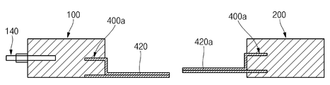
- the secondary battery 10 includes two electrode assemblies 100 and 200, an electrode assembly 100 and 200, and a case for accommodating an electrolyte ( 300), and a connection tab 400 connecting the two electrode assemblies 100 and 200.
- One of the two electrode assemblies 100 and 200 includes a first tab 140 and a second tab 150 respectively drawn out from the electrode assemblies 100 and 200.
- the insulating tape 500 may be attached to the first tab 140, the second tab 150 and the connection tab 400.
- the electrode assemblies 100 and 200 provided with the first tab 140 and the second tab 150 are defined as the first electrode assembly 100, and the other is defined as the second electrode assembly 200.
- the first electrode assembly 100 includes a first electrode plate 110 and a second electrode plate 120, and a separator 130 that physically separates them. It is formed by winding a unit stack or stacking it in a plurality of layers.
- the first tab 140 and the second tab 150 may be electrically connected to any one of the first electrode plate 110 and the second electrode plate 120, respectively.
- the first electrode plate 110 may be a positive electrode plate made of a mixture including an aluminum substrate and an active material.
- the second electrode plate 120 may be a negative electrode plate made of a mixture including a copper substrate and an active material.
- the first electrode plate 110 may be configured as a negative electrode plate and the second electrode plate 120 may be configured as a positive electrode plate.
- the separator 130 is provided in plural and is inserted between the plurality of first electrode plates 110 and the second electrode plates 120, respectively.
- the separator 130 is an insulator that prevents a short circuit between the first electrode plate 110 and the second electrode plate 120.
- the first tab 140 is electrically connected to the first electrode plate 110
- the second tab 150 is electrically connected to the second electrode plate 120.
- One end of the first tab 140 and the second tab 150 partially protrudes to the outside of the first electrode plate 110 and the second electrode plate 120 to electrically connect the electrode assemblies 100 and 200 with the outside do.
- the first electrode plate 110 is a positive electrode
- the first tab 140 becomes a positive electrode tab
- the second electrode plate 120 is a negative electrode plate
- the second tab 150 becomes a negative electrode tab.
- the first tab 140 and the second tab 150 are spaced apart from each other by a predetermined distance and are drawn out in the same direction.
- the first tab 140 and the second tab 150 are a boundary portion extending out of the case 300 or an inner surface including a boundary portion (contact with the first electrode plate and the second electrode plate).
- the insulating tape 500 may be attached to the surface that is not. The insulating tape 500 prevents a short circuit between the first tab 140 and the second tab 150.
- the second electrode assembly 200 is connected in parallel with the first electrode assembly 100 by a connection tab 400 to be described later.
- the second electrode assembly 200 includes a first electrode plate 210 and a second electrode plate 220 in the same manner as the first electrode assembly 100 except for the first tab 140 and the second tab 150.
- a separator 230 is provided.
- the second electrode assembly 200 may have the same size and capacity as the first electrode assembly 100 or may be formed differently in size and capacity (see FIGS. 6 and 7 ).
- connection tab 400 is formed of the first electrode assembly 100 and the second electrode assembly 200. Can be placed in the center. 6, when the size and capacity of the first electrode assembly 100 is larger than the second electrode assembly 200, the connection tab 400 is disposed on one side of the first electrode assembly 100 It may be disposed in the center of the electrode assembly 200. Conversely, when the size and capacity of the second electrode assembly 200 is larger than that of the first electrode assembly 100 as shown in FIG. 7, the connection tab 400 is disposed on one side of the second electrode assembly 200 1 It may be disposed in the center of the electrode assembly 100.
- the first electrode assembly 100 and the second electrode assembly 200 are accommodated in the case 300 while being connected to the connection tab 400.
- the case 300 may include a receiving portion 310 forming an accommodation space 310a and a cover 320 covering one surface of the receiving portion 310. .
- the case 300 accommodates the first electrode assembly 100 and the second electrode assembly 200 together with an electrolyte.
- the case 300 is bonded to the cover 320 and sealed in a state in which the first electrode assembly 100 and the second electrode assembly 200 are accommodated.
- the case 300 is folded so that one side of the cover 320 is in surface contact with the other side.
- the accommodating part 310 may have a box shape with one side open to form the accommodating space 310a.
- the accommodation space 310a has a size and shape corresponding to the size and shape of the first electrode assembly 100 and the second electrode assembly 200.
- a bonding portion 312 extending vertically outward from the end of the receiving portion 310 is formed along the opened edge of the receiving portion 310.
- the bonding portion 312 is a portion that is bonded to the cover 320 by various methods such as fusion bonding or bonding.
- An incision groove 330 is formed in the junction 312 corresponding to the position of the folded portion when the receiving portion 310 is folded.
- the incision groove 330 is a groove having a shape such as a semicircular shape or a'V' shape, and is formed by cutting a part of an end portion of the joint portion 312.
- a cutout groove 330 is formed on the junction 312 corresponding to the portion where the case 300 is folded.
- the incision groove 330 is not limited to the above-described semicircular or V'-shaped shape as long as the folding portion of the case 300 can be smoothly folded.
- the cover 320 covers the opened side of the receiving part 310, it has a rectangular plate shape corresponding to the size and shape of the receiving part 310 and the junction part 312. The edge of the cover 320 is bonded to the bonding portion 312 so that the receiving portion 310 and the cover 320 are fixed.
- the cover 320 is folded together with the receiving portion 310 when the case 300 is folded in half. Accordingly, a cutout groove 330 having the same shape as the cutout groove 330 is formed on the cover 320 at a position of the end where the cutout groove 330 is formed.
- the cover 320 When the case 300 is folded in half, the cover 320 may have one end and the other end of the outer surface in close contact with each other, and the folding portion may also be in close contact with each other.
- connection tab that can be flexibly bent in order to stably maintain the electrical connection state between the first electrode assembly 100 and the second electrode assembly 200 ( 400) is essential.
- connection tab 400 is disposed between the first electrode assembly 100 and the second electrode assembly 200.
- the connection tab 400 is provided on each of the first electrode assembly 100 and the second electrode assembly 200, and includes two tabs of the positive connection tab 400 and the negative connection tab 400. That is, each of the first electrode assembly 100 and the second electrode assembly 200 includes a pair of connection tabs 400.
- the positive electrode connection tab 400 is electrically connected to the aluminum substrate provided on the first electrode plate 110 of each of the first electrode assembly 100 and the second electrode assembly 200.
- the cathode connection tab 400 is electrically connected to a copper substrate provided on the second electrode plate 120 of each of the first electrode assembly 100 and the second electrode assembly 200.
- each of the positive connection tab 400 and the negative connection tab 400 may be provided one by one (hereinafter, a one-tap structure), as shown in FIGS. 8A to 9D.
- a pair may be provided (hereinafter, a two-tap structure).
- connection tabs 400 includes a substrate contacting portion 410 electrically connected to an internal substrate of the first electrode assembly 100 or the second electrode assembly 200, and the first electrode assembly 100 or the second electrode assembly. It consists of a connection portion 420 exposed to the outside of the 200. However, the base contact part 410 and the connection part 420 are not separately formed, and one connection tab 400 is defined by dividing into the base contact part 410 and the connection part 420 according to the position.
- the substrate contact portion 410 is inserted into the first electrode plate 110 or the second electrode plate 120 and is electrically connected to the aluminum substrate or the copper substrate by making surface contact. That is, the substrate contact portion 410 of the anode connection tab 400 is electrically connected to the aluminum substrate, and the substrate contact portion 410 of the cathode connection tab 400 is electrically connected to the copper substrate.
- the positive electrode connection tab 400 is arranged in line with the first tab 140, which is an anode tab, and the negative connection tab 400 is arranged in line with the second tab 150, which is a negative electrode tab.
- the two electrode assemblies 200 are connected in parallel.
- the connection portion 420 integrally formed with the substrate contact portion 410 is exposed to the outside of the first electrode assembly 100 and the second electrode assembly 200.
- connection part 420 is exposed to be disposed between the first electrode assembly 100 and the second electrode assembly 200. That is, the connection tabs 400 respectively connected to the first electrode assembly 100 and the second electrode assembly 200 are disposed so that the connection portions 420 face each other. The connection portions 420 of the connection tabs 400 facing each other are coupled to each other by overlapping predetermined sections.
- connection part 420 is coupled to enable electrical connection by a method such as welding.
- a method such as welding.
- an insulating tape 500 may be attached on the connection part 420.
- the insulating tape 500 may be attached to cover a larger area than the welding area.
- the insulating tape 500 may not be attached to the connection part 420 and the insulator may be bonded together when the connection part 420 is combined with the insulator attached to the connection part 420 in advance.
- connection tab 400 When the secondary battery 10 is folded, the connection tab 400 is folded around a point on the connection part 420 to which the insulating tape 500 is not attached (see line AA in FIG. 5, hereinafter defined as a folding line) ). Attachment of the insulating tape 500 may be selectively applied.
- connection tab 400 may have a thickness thinner than the first tab 140 and the second tab 150 described above so that the secondary battery 10 can be easily folded around the connection part 420. Accordingly, the thickness of the folding portion is not increased, and the electrical connection between the two electrode assemblies is maintained, and the folding portion can be flexibly bent.
- connection tabs 400 of the first electrode assembly 100 and the second electrode assembly 200 will be described in detail (for convenience, the connection tab of the second electrode assembly is a connection tab of the first electrode assembly). It is described as 420a to distinguish it from).
- 8A to 10C are cross-sectional views illustrating various connection types and folding processes of an electrode assembly according to an embodiment of the present invention.
- the secondary battery 10 may include an insulating tape 500 or a two-tap connection tab 400 without an insulator ( In the drawings, only the positive electrode connection tab is shown for convenience).
- connection portions 420 and 420a of the connection tab 400 are formed to have a sufficient length to maintain electrical connection between the first electrode assembly 100 and the second electrode assembly 200 when the secondary battery 10 is folded ( 8d).
- the cover 320 is positioned between the first electrode assembly 100 and the second electrode assembly 200, so the length of the connection tab 400 is preferably formed in consideration of this.
- connection part 420 provided in the first electrode assembly 100 and the connection part 420a provided in the second electrode assembly 200 must be welded by overlapping each other, the connection parts 420 and 420a on the upper side based on FIG. 8A ) Is formed longer than the lower side.
- the longer connecting portions 420 and 420a are bent and adhered to the lower connecting portion 420 (see FIG. 8B), and two connecting portions 420 and 420a are welded to each other by welding with the facing connecting portions 420 and 420a. Fix each other (see Fig. 8c).
- the welding portion is bent, so that the anode connection tab 400 of the second electrode assembly 200 is connected to the anode connection tab 400 of the first electrode assembly 100. It can be formed to have a stepped height. Accordingly, after welding, the lower surface of the welding portion to which the two connecting portions 420 and 420a are welded may be maintained horizontally without bending or bending.
- the secondary battery 10 may include an insulating tape 500 or a connection tab 400 having a two-tap structure provided with an insulator ( In the drawings, only the positive electrode connection tab is shown for convenience).
- connection tabs 400 are coupled to each other in the same structure as the structures of 8a to 8d, and the insulating tape 500 may be adhered to the bonding portion or the insulators may be mutually bonded.
- the secondary battery 10 may include an insulating tape 500 or a connection tab 400 having a one-tap structure without an insulator. Yes (only the positive electrode connection tab is shown in the drawings for convenience).
- connection tabs 400 facing each other are disposed to have a stepped height, and are overlapped and welded to each other in the same manner as in the structure of 8a to 8d.
- the insulating tape 500 may be adhered to the bonding portion of the one-tap structure or the insulator may be bonded to each other (not shown).
- connection tab 400 has a thickness thinner than that of the first tab 140 and the second tab 150 has been described.
- a rechargeable battery 10 according to another embodiment of the present invention will be described (for the same configuration as the above-described embodiment, the same reference numerals will be used, but detailed descriptions of overlapping features will be omitted) To).
- 11 is a plan view illustrating an electrode assembly of a secondary battery according to another embodiment of the present invention.
- 12A to 12C are cross-sectional views illustrating a connection form and a folding process of an electrode assembly according to another embodiment of the present invention.
- a secondary battery 10 ′ has the same structure as the secondary battery 10 of the above-described embodiment, but a first generally used instead of a connection tab having a thin thickness.
- the first electrode assembly 100 ′ and the second electrode assembly 200 ′ may be electrically connected using the tab 140 ′ and the second tab 150 ′.
- connection tab 400 ′ is formed on the second electrode assembly 200 ′, but the connection tab 400 ′ is the same general electrode tab as the first tab 140 ′ and the second tab 150 ′, and the first It is disposed to have a stepped height with the tab 140' and the second tab 150'.
- the connection tab 400 ′ may be electrically connected to the first tab 140 ′ and the second tab 150 ′ by a bonding method such as welding.
- connection tab 400' in the secondary battery 10' is the same as the first tab 140' and the second tab 150'. It is formed to have a thickness.
- connection tab 400 ′ of FIGS. 12A to 12C is thicker than the connection tab 400 disclosed in the embodiment of FIGS. 8A to 10C, the connection tab 400 ′ itself is not a material that does not bend due to high rigidity. . Accordingly, if the connection tab 400 ′ has a sufficient length, the secondary battery 10 ′ can be folded.
- first electrode assembly and the second electrode assembly are connected in parallel.
- first electrode assembly and the second electrode assembly may be connected in series (not shown).
- a separation wall is provided between the first electrode assembly and the second electrode assembly to block electrolytes from communicating with each other, thereby preventing a short circuit between the first electrode assembly and the second electrode assembly.
- the present invention can be used in the field of secondary batteries in which an electrode assembly is formed to be foldable.
Landscapes
- Chemical & Material Sciences (AREA)
- Chemical Kinetics & Catalysis (AREA)
- Electrochemistry (AREA)
- General Chemical & Material Sciences (AREA)
- Engineering & Computer Science (AREA)
- Manufacturing & Machinery (AREA)
- Materials Engineering (AREA)
- Connection Of Batteries Or Terminals (AREA)
- Sealing Battery Cases Or Jackets (AREA)
- Cell Electrode Carriers And Collectors (AREA)
- Secondary Cells (AREA)
Abstract
본 발명은 이차 전지에 관한 것으로, 제1 탭 및 제2 탭을 구비한 제1 전극 조립체; 상기 제1 전극 조립체와 전기적으로 연결되는 제2 전극 조립체; 상기 제1 전극 조립체 및 상기 제2 전극 조립체의 사이에 배치되되 상기 제1 전극 조립체 및 상기 제2 전극 조립체에 각각 연결되며, 상기 제1 전극 조립체와 상기 제2 전극 조립체를 전기적으로 연결하는 복수의 연결 탭; 및 상기 제1 전극 조립체 및 상기 제2 전극 조립체와 전해액을 수용하는 수용 공간이 형성되고 일측이 개구된 수용부, 상기 수용부의 개구된 일측에 결합되어 상기 수용부의 개구된 일측을 커버하는 커버를 구비한 케이스를 포함하고, 상기 케이스의 폴딩 시 상기 커버의 외측면 일단 및 타단이 밀착되도록 폴딩되는 것을 특징으로 한다.
Description
본 발명의 다양한 실시예는 이차 전지에 관한 것이다.
일반적으로 노트북, 미니 노트북, 넷북, 모바일 컴퓨터, UMPC(Ultra Mobile Personal Computer) 및 PMP(Portable Multimedia Player)와 같은 전자 장치는 이동형 전원으로서 다수의 이차 전지 또는 배터리 셀이 직렬 및/또는 병렬로 연결되어 이루어진 배터리 팩을 이용한다. 이러한 배터리 팩은 과충전, 과방전 및/또는 과전류로부터 이차 전지를 보호하기 위한 보호회로모듈(PCM: protective circuit module)을 포함하며, 상기 이차 전지 및 보호회로모듈은 케이스에 함께 내장될 수 있다.
이러한 발명의 배경이 되는 기술에 개시된 상술한 정보는 본 발명의 배경에 대한 이해도를 향상시키기 위한 것뿐이며, 따라서 종래 기술을 구성하지 않는 정보를 포함할 수도 있다.
본 발명은 하나의 케이스 내에 2개의 전극 조립체를 병렬 또는 직렬 연결하는 연결 구조를 구비함으로써 전극 조립체를 폴딩 가능하게 형성한 이차 전지를 제공한다.
본 발명의 실시예에 따른 이차 전지는 제1 탭 및 제2 탭을 구비한 제1 전극 조립체; 상기 제1 전극 조립체와 전기적으로 연결되는 제2 전극 조립체; 상기 제1 전극 조립체 및 상기 제2 전극 조립체의 사이에 배치되되 상기 제1 전극 조립체 및 상기 제2 전극 조립체에 각각 연결되며, 상기 제1 전극 조립체와 상기 제2 전극 조립체를 전기적으로 연결하는 복수의 연결 탭; 및 상기 제1 전극 조립체 및 상기 제2 전극 조립체와 전해액을 수용하는 수용 공간이 형성되고 일측이 개구된 수용부, 상기 수용부의 개구된 일측에 결합되어 상기 수용부의 개구된 일측을 커버하는 커버를 구비한 케이스를 포함하고, 상기 케이스의 폴딩 시 상기 커버의 외측면 일단 및 타단이 밀착되도록 폴딩될 수 있다.
상기 케이스의 폴딩 시 상기 커버의 폴딩 부위가 밀착될 수 있다.
상기 케이스는 상기 수용부의 개구된 일측 가장자리를 따라 연장 형성되되 상기 커버와 수평이 되도록 연장되어 상기 커버에 결합되는 접합부를 더 포함할 수 있다.
상기 접합부 및 상기 커버는 상기 케이스의 폴딩 시 상기 폴딩 부위에 대응하는 단부가 절개되어 절개홈이 형성될 수 있다.
상기 제1 전극 조립체 및 상기 제2 전극 조립체는 제1 전극판 및 제2 전극판과, 상기 제1 전극판 및 상기 제2 전극판의 사이에 삽입되는 세퍼레이터를 각각 포함하고, 상기 제1 전극 조립체는 상기 제1 전극판 및 상기 제2 전극판에 각각 전기적으로 연결된 제1 탭 및 제2 탭을 더 포함할 수 있다.
상기 제1 전극판은 알루미늄 기재를 구비한 양극판이고, 상기 제2 전극판은 구리 기재를 구비한 음극판이며, 상기 연결 탭은 상기 제1 전극판 및 상기 제2 전극판에 각각 전기적으로 연결되는 양극 연결 탭 및 음극 연결 탭을 포함한다.
상기 제1 전극 조립체의 상기 양극 연결 탭은 상기 알루미늄 기재에 연결되는 기재 접촉부와, 상기 기재 접촉부와 일체로 형성되고 상기 1 전극 조립체의 일측으로 노출되는 연결부를 포함하고, 상기 제1 전극 조립체의 상기 음극 연결 탭은 상기 구리 기재에 연결되는 기재 접촉부와, 상기 기재 접촉부와 일체로 형성되고 상기 1 전극 조립체의 일측으로 노출되는 연결부를 포함하며, 상기 제2 전극 조립체의 상기 양극 연결 탭은 상기 알루미늄 기재에 연결되는 기재 접촉부와, 상기 기재 접촉부와 일체로 형성되고 상기 1 전극 조립체를 향해 노출되는 연결부를 포함하고, 상기 제2 전극 조립체의 상기 음극 연결 탭은 상기 구리 기재에 연결되는 기재 접촉부와, 상기 기재 접촉부와 일체로 형성되고 상기 1 전극 조립체를 향해 노출되는 연결부를 포함한다.
상기 양극 연결 탭 및 음극 연결 탭은 하나 또는 두 개로 구비될 수 있다.
상기 제1 전극 조립체에 연결된 상기 연결 탭과 상기 제2 전극 조립체에 연결된 상기 연결 탭은 상호 중첩될 수 있다.
상기 제1 전극 조립체에 연결된 상기 연결 탭과 상기 제2 전극 조립체에 연결된 상기 연결 탭은 서로 단차지게 배치될 수 있다.
상기 제1 전극 조립체에 연결된 상기 연결 탭과 상기 제2 전극 조립체에 연결된 상기 연결 탭의 결합 부위에는 절연 테이프가 접착될 수 있다.
상기 제1 전극 조립체와 상기 제2 전극 조립체는 병렬로 연결될 수 있다.
상기 제1 전극 조립체와 상기 제2 전극 조립체는 직렬로 연결되고, 상기 수용 공간은 2개로 분할되어 상기 전해액이 서로 연통되지 않도록 상기 제1 전극 조립체와 상기 제2 전극 조립체를 각각 수용할 수 있다.
본 발명의 일 실시예에 따른 이차 전지는 하나의 케이스 내에 2개의 전극 조립체를 병렬 또는 직렬로 연결하고, 각 전극 조립체를 일반 탭 또는 기재 탭을 이용해 폴딩 가능하게 연결한다. 따라서 이차 전지의 폴딩이 가능하며, 폴딩 부위의 내구성을 확보할 수 있다.
즉, 본 발명의 일 실시예는 하나의 케이스 내에 2개의 전극 조립체를 병렬 또는 직렬 연결하는 연결 구조를 구비함으로써 이차 전지를 폴딩 가능하게 형성한 이차 전지를 제공한다.
도 1은 본 발명의 일 실시 예에 따른 이차 전지의 폴딩 상태를 도시한 결합 사시도이다.
도 2는 도 1에 따른 이차 전지의 펼친 상태를 도시한 결합 사시도이다.
도 3은 도 2에 따른 이차 전지의 분해 사시도이다.
도 4는 도 3에 따른 이차 전지의 전극 조립체를 도시한 평면도이다.
도 5는 도 4에 따른 전극 조립체의 연결 상태를 도시한 평면도이다.
도 6 및 도 7은 본 발명에 따른 전극 조립체의 여러 형태를 도시한 평면도이다.
도 8a 내지 도 10c는 본 발명의 일 실시 예에 따른 전극 조립체의 다양한 연결 형태 및 폴딩 과정을 도시한 단면도이다.
도 11은 본 발명의 다른 실시 예에 따른 이차 전지의 전극 조립체를 도시한 평면도이다.
도 12a 내지 도12c는 본 발명의 다른 실시 예에 따른 전극 조립체의 연결 형태 및 폴딩 과정을 도시한 단면도이다.
이하, 첨부된 도면을 참조하여 본 발명의 바람직한 실시예를 상세히 설명하기로 한다.
본 발명의 실시예들은 당해 기술 분야에서 통상의 지식을 가진 자에게 본 발명을 더욱 완전하게 설명하기 위하여 제공되는 것이며, 하기 실시예는 여러 가지 다른 형태로 변형될 수 있으며, 본 발명의 범위가 하기 실시예에 한정되는 것은 아니다. 오히려, 이들 실시예는 본 개시를 더욱 충실하고 완전하게 하고, 당업자에게 본 발명의 사상을 완전하게 전달하기 위하여 제공되는 것이다.
또한, 이하의 도면에서 각 층의 두께나 크기는 설명의 편의 및 명확성을 위하여 과장된 것이며, 도면상에서 동일 부호는 동일한 요소를 지칭한다. 본 명세서에서 사용된 바와 같이, 용어 "및/또는"은 해당 열거된 항목 중 어느 하나 및 하나 이상의 모든 조합을 포함한다. 또한, 본 명세서에서 "연결된다"라는 의미는 A 부재와 B 부재가 직접 연결되는 경우뿐만 아니라, A 부재와 B 부재의 사이에 C 부재가 개재되어 A 부재와 B 부재가 간접 연결되는 경우도 의미한다.
본 명세서에서 사용된 용어는 특정 실시예를 설명하기 위하여 사용되며, 본 발명을 제한하기 위한 것이 아니다. 본 명세서에서 사용된 바와 같이, 단수 형태는 문맥상 다른 경우를 분명히 지적하는 것이 아니라면, 복수의 형태를 포함할 수 있다. 또한, 본 명세서에서 사용되는 경우 "포함한다(comprise)" 및/또는 "포함하는(comprising)"은 언급한 형상들, 숫자, 단계, 동작, 부재, 요소 및/또는 이들 그룹의 존재를 특정하는 것이며, 하나 이상의 다른 형상, 숫자, 동작, 부재, 요소 및 /또는 그룹들의 존재 또는 부가를 배제하는 것이 아니다.
본 명세서에서 제1, 제2 등의 용어가 다양한 부재, 부품, 영역, 층들 및/또는 부분들을 설명하기 위하여 사용되지만, 이들 부재, 부품, 영역, 층들 및/또는 부분들은 이들 용어에 의해 한정되어서는 안 됨은 자명하다. 이들 용어는 하나의 부재, 부품, 영역, 층 또는 부분을 다른 영역, 층 또는 부분과 구별하기 위하여만 사용된다. 따라서, 이하 상술할 제1부재, 부품, 영역, 층 또는 부분은 본 발명의 가르침으로부터 벗어나지 않고서도 제2부재, 부품, 영역, 층 또는 부분을 지칭할 수 있다.
"하부(beneath)", "아래(below)", "낮은(lower)", "상부(above)", "위(upper)"와 같은 공간에 관련된 용어가 도면에 도시된 한 요소 또는 특징과 다른 요소 또는 특징의 용이한 이해를 위해 이용된다. 이러한 공간에 관련된 용어는 본 발명의 다양한 공정 상태 또는 사용 상태에 따라 본 발명의 용이한 이해를 위한 것이며, 본 발명을 한정하기 위한 것은 아니다. 예를 들어, 도면의 요소 또는 특징이 뒤집어지면, "하부" 또는 "아래"로 설명된 요소는 "상부" 또는 "위에"로 된다. 따라서, "아래"는 "상부" 또는 "아래"를 포괄하는 개념이다.
본 발명의 주요 구성을 설명함에 있어 편의상 도 1을 기준으로 위쪽을 상측 방향, 아래쪽을 하측 방향으로 정의하기로 한다. 또한, 도 1을 기준으로 케이스의 장변 방향을 길이 방향, 케이스의 단변 방향을 폭 방향으로, 케이스의 외부를 향하는 방향을 외측 방향으로, 케이스의 수용 공간을 향하는 방향을 내측 방향으로 정의한다. 따라서 각 구성품들의 결합 관계는 이러한 배치 방향이 변경되는 경우 그에 대응하여 달라지는 개념을 모두 포함한다.
도 1은 본 발명의 일 실시 예에 따른 이차 전지의 폴딩 상태를 도시한 결합 사시도이다. 도 2는 도 1에 따른 이차 전지의 펼친 상태를 도시한 결합 사시도이다. 도 3은 도 2에 따른 이차 전지의 분해 사시도이다. 도 4는 도 3에 따른 이차 전지의 전극 조립체를 도시한 평면도이다. 도 5는 도 4에 따른 전극 조립체의 연결 상태를 도시한 평면도이다. 도 6 및 도 7은 본 발명에 따른 전극 조립체의 여러 형태를 도시한 평면도이다.
도 1 내지 도 3에 도시된 바와 같이, 본 발명의 일 실시 예에 따른 이차 전지(10)는 2개의 전극 조립체(100, 200)와, 전극조립체(100, 200) 및 전해액을 수용하는 케이스(300), 2개의 전극 조립체(100, 200) 사이를 연결하는 연결 탭(400)을 포함한다. 2개의 전극 조립체(100, 200) 중 어느 하나는 전극 조립체(100, 200)로부터 외부로 각각 인출된 제1 탭(140) 및 제2 탭(150)을 포함한다. 제1 탭(140) 및 제2 탭(150), 연결 탭(400)에는 절연 테이프(500)가 부착될 수 있다.
편의상 제1 탭(140) 및 제2 탭(150)이 구비된 전극 조립체(100, 200)를 제1 전극 조립체(100)라고 정의하고, 다른 하나를 제2 전극 조립체(200)라고 정의한다.
도 1, 도 3 내지 도 5에 도시된 바와 같이, 제1 전극 조립체(100)는 제1 전극판(110) 및 제2 전극판(120), 이들을 물리적으로 분리하는 세퍼레이터(130)가 적층된 단위 적층체를 권취하거나 복수 개의 층으로 적층하여 형성된다. 제1 전극판(110) 및 제2 전극판(120) 중 어느 하나에는 제1 탭(140) 및 제2 탭(150)이 각각 전기적으로 연결될 수 있다.
제1 전극판(110)은 알루미늄 기재와, 활물질을 포함하는 합제로 구성된 양극판일 수 있다. 제2 전극판(120)은 구리 기재와, 활물질을 포함하는 합제로 구성된 음극판일 수 있다. 그러나 제1 전극판(110)이 음극판으로 구성되고 제2 전극판(120)이 양극판으로 구성될 수도 있다. 세퍼레이터(130)는 복수 개로 구비되어 복수의 제1 전극판(110)과 제2 전극판(120)의 사이에 각각 삽입된다. 세퍼레이터(130)는 제1 전극판(110) 및 제2 전극판(120) 간의 단락을 방지하는 절연체이다.
제1 탭(140)은 제1 전극판(110)과 전기적으로 연결되고, 제2 탭(150)은 제2 전극판(120)과 전기적으로 연결된다. 제1 탭(140) 및 제2 탭(150)은 제1 전극판(110) 및 제2 전극판(120)의 외측으로 일단이 일부 돌출되어 전극 조립체(100, 200)를 외부와 전기적으로 연결한다. 제1 전극판(110)이 양극판 일 때 제1 탭(140)은 양극 탭이 되고, 제2 전극판(120)이 음극판 일 때 제2 탭(150)은 음극 탭이 된다. 제1 탭(140) 및 제2 탭(150)은 서로 소정 간격 이격되며, 동일한 방향으로 인출된다.
제1 탭(140) 및 제2 탭(150)은 케이스(300)의 외부로 인출되는 경계가 되는 부분이나, 경계가 되는 부분을 포함하는 내측 일면(제1 전극판 및 제2 전극판과 접촉되지 않는 면)에 절연 테이프(500)가 부착될 수 있다. 절연 테이프(500)는 제1 탭(140) 및 제2 탭(150)의 단락을 방지한다.
도 1, 도 3 내지 도 5에 도시된 바와 같이, 제2 전극 조립체(200)는 후술할 연결 탭(400)에 의해 제1 전극 조립체(100)와 병렬로 연결된다. 제2 전극 조립체(200)는 제1 탭(140)과 제2 탭(150)을 제외하고 제1 전극 조립체(100)와 동일하게 제1 전극판(210) 및 제2 전극판(220), 세퍼레이터(230)를 구비한다. 제2 전극 조립체(200)는 제1 전극 조립체(100)와 크기와 용량이 동일하게 형성될 수도 있고, 크기와 용량이 다르게 형성될 수도 있다(도 6 및 도 7 참조).
도 5에서와 같이 제1 전극 조립체(100)와 제2 전극 조립체(200)의 크기와 용량이 동일한 경우, 연결 탭(400)은 제1 전극 조립체(100)와 제2 전극 조립체(200)의 중앙에 배치될 수 있다. 도 6에서와 같이 제1 전극 조립체(100)의 크기 및 용량이 제2 전극 조립체(200)보다 크게 형성되는 경우, 연결 탭(400)은 제1 전극 조립체(100)의 일측에 배치되되 제2 전극 조립체(200)의 중앙에 배치될 수 있다. 반대로 도 7에서와 같이 제2 전극 조립체(200)의 크기 및 용량이 제1 전극 조립체(100)보다 크게 형성되는 경우, 연결 탭(400)은 제2 전극 조립체(200)의 일측에 배치되되 제1 전극 조립체(100)의 중앙에 배치될 수 있다.
제1 전극 조립체(100) 및 제2 전극 조립체(200)은 연결 탭(400)에 연결된 상태로 케이스(300) 내부에 수용된다.
도 1 내지 도 3에 도시된 바와 같이, 케이스(300)는 수용 공간(310a)을 형성하는 수용부(310)와, 수용부(310)의 일면을 커버하는 커버(320)를 포함할 수 있다. 케이스(300)는 전해액과 함께 제1 전극 조립체(100) 및 제2 전극 조립체(200)를 수용한다. 케이스(300)는 제1 전극 조립체(100) 및 제2 전극 조립체(200)가 수용된 상태에서 커버(320)와 접합되어 밀봉된다. 케이스(300)는 커버(320)의 일측이 타측과 면접촉되도록 폴딩(folding, 접힘)된다.
수용부(310)는 수용 공간(310a)을 형성하기 위해 일측이 개구된 박스 형상을 가질 수 있다. 수용 공간(310a)은 제1 전극 조립체(100) 및 제2 전극 조립체(200)의 크기와 형상에 대응하는 크기와 형상을 갖는다. 수용부(310)의 개구된 일측 가장자리를 따라 수용부(310)의 단부로부터 수직하게 외측으로 연장된 접합부(312)가 형성된다.
접합부(312)는 융착 또는 접착 등 여러 방법으로 커버(320)와 접합되는 부분이다. 접합부(312)에는 수용부(310)가 폴딩될 때 접히는 부분의 위치에 대응하여 절개홈(330)이 형성된다.
절개홈(330)은 반원형 또는 'V'자형 등의 형상을 갖는 홈으로, 접합부(312)의 단부 일부를 절개하여 형성된다. 케이스(300)가 반으로 접히게 되면 접합부(312)와 커버(320)가 접히는 부분의 두께가 두꺼워지므로 주름이 발생하거나 들뜸 현상이 발생할 수 있다. 접힘 부위가 들뜨거나 주름이 생기면 케이스(300)가 완전히 접히지 못하고 폴딩 상태가 해제될 수 있다. 따라서 이러한 문제를 방지하기 위해 케이스(300)가 접히는 부분에 대응하는 접합부(312) 상에 절개홈(330)을 형성한다.
절개홈(330)은 케이스(300)의 폴딩 부위가 원활하게 접힐 수 있다면 전술한 반원형이나 V'자형 형상에 제한되지 않는다.
커버(320)는 수용부(310)의 개구된 일측을 커버하므로 수용부(310) 및 접합부(312)의 크기 및 형상에 대응하여 직사각형의 판(plate) 형태를 갖는다. 커버(320)의 가장자리가 접합부(312)와 접합되어 수용부(310)와 커버(320)가 고정된다.
커버(320)는 케이스(300)가 반으로 접힐 때 수용부(310)와 함께 폴딩된다. 따라서 커버(320) 상에도 절개홈(330)이 형성되는 단부의 위치에 절개홈(330)과 동일한 형상의 절개홈(330)이 형성된다.
커버(320)는 케이스(300)가 반으로 접힐 때 외측면의 일단 및 타단이 상호 밀착되고 폴딩 부위 역시 밀착될 수 있다.
전술한 바와 같이, 케이스(300)가 반으로 완전히 폴딩될 때 제1 전극 조립체(100)와 제2 전극 조립체(200)간의 전기적 연결 상태를 안정적으로 유지하기 위해 유연하게 휘어질 수 있는 연결 탭(400)이 필수적이다.
도 1, 도 4 및 도 5에 도시된 바와 같이, 연결 탭(400)은 제1 전극 조립체(100)와 제2 전극 조립체(200)의 사이에 배치된다. 연결 탭(400)은 제1 전극 조립체(100) 및 제2 전극 조립체(200)에 각각 구비되며, 양극 연결 탭(400) 및 음극 연결 탭(400)의 2가지 탭으로 구성된다. 즉, 제1 전극 조립체(100) 및 제2 전극 조립체(200)는 각각 한 쌍의 연결 탭(400)을 구비하게 된다.
양극 연결 탭(400)은 제1 전극 조립체(100) 및 제2 전극 조립체(200) 각각의 제1 전극판(110)에 구비된 알루미늄 기재에 전기적으로 연결된다. 음극 연결 탭(400)은 제1 전극 조립체(100) 및 제2 전극 조립체(200) 각각의 제2 전극판(120)에 구비된 구리 기재에 전기적으로 연결된다.
또한, 도 10a 내지 도 10d에 도시된 바와 같이 각 양극 연결 탭(400) 및 음극 연결 탭(400)은 하나씩 구비될 수도 있고(이하, 원 탭 구조), 도 8a 내지 도 9d에 도시된 바와 같이 한 쌍씩 구비될 수도 있다(이하, 투 탭 구조). 양극 연결 탭(400) 및 음극 연결 탭(400)이 한 쌍씩 구비되는 경우, 2개의 전극 조립체 사이에 배치되는 연결 탭(400)은 총 8개가 된다.
각각의 연결 탭(400)은 제1 전극 조립체(100) 또는 제2 전극 조립체(200)의 내부 기재에 전기적으로 연결되는 기재 접촉부(410)와, 제1 전극 조립체(100) 또는 제2 전극 조립체(200)의 외부로 노출되는 연결부(420)로 구성된다. 그러나 기재 접촉부(410)와 연결부(420)가 별도로 형성되는 것은 아니며, 하나의 연결 탭(400)을 위치에 따라 기재 접촉부(410) 및 연결부(420)로 구분하여 정의한 것이다.
도 5에 도시된 바와 같이, 기재 접촉부(410)는 제1 전극판(110) 또는 제2 전극판(120) 내부에 삽입되어 알루미늄 기재 또는 구리 기재에 면접촉하여 전기적으로 연결된다. 즉, 양극 연결 탭(400)의 기재 접촉부(410)는 알루미늄 기재와 전기적으로 연결되며, 음극 연결 탭(400)의 기재 접촉부(410)는 구리 기재와 전기적으로 연결된다. 양극 연결 탭(400)은 양극 탭인 제1 탭(140)과 일렬로 배치되고, 음극 연결 탭(400)은 음극 탭인 제2 탭(150)과 일렬로 배치되어 제1 전극 조립체(100) 및 제2 전극 조립체(200)가 병렬 연결된다. 기재 접촉부(410)와 일체로 형성된 연결부(420)는 제1 전극 조립체(100) 및 제2 전극 조립체(200)의 외부로 노출된다.
연결부(420)는 제1 전극 조립체(100)와 제2 전극 조립체(200)의 사이에 배치되도록 노출된다. 즉, 제1 전극 조립체(100)와 제2 전극 조립체(200)에 각각 연결되는 연결 탭(400)은 연결부(420)가 서로 마주보도록 배치된다. 서로 마주보는 연결 탭(400)의 연결부(420)는 소정 구간이 중첩되어 상호 결합된다.
연결부(420)는 용접 등의 방법으로 전기적인 연결이 가능하도록 결합된다. 연결부(420)와 주변부와의 단락 방지를 위해 연결부(420) 상에 절연 테이프(500)가 부착될 수 있다. 절연 테이프(500)는 용접 부위보다 넓은 면적을 커버하도록 부착될 수 있다. 또는, 연결부(420)에 절연 테이프(500)가 부착되지 않고 연결부(420) 상에 절연체가 미리 부착된 상태로 연결부(420)간의 결합 시 절연체를 함께 결합시킬 수도 있다.
이차 전지(10)가 폴딩될 때 절연 테이프(500)가 부착되지 않은 연결부(420) 상의 한 지점을 중심으로 연결 탭(400)이 폴딩된다(도 5의 A-A선 참조, 이하 폴딩 라인으로 정의함). 절연 테이프(500)의 부착은 선택적으로 적용될 수 있다.
연결부(420)를 중심으로 이차 전지(10)가 쉽게 폴딩될 수 있도록 연결 탭(400)은 전술한 제1 탭(140) 및 제2 탭(150) 보다 얇은 두께를 가질 수 있다. 따라서 폴딩 부위의 두께가 증가하지 않으면서 2개의 전극 조립체간 전기적 연결을 유지하며 폴딩 부위가 유연하게 굽혀질 수 있다.
이하에서는 제1 전극 조립체(100) 및 제2 전극 조립체(200)의 연결 탭(400)간 결합 상태에 대해 상세히 설명하기로 한다(편의상 제2 전극 조립체의 연결 탭은 제1 전극 조립체의 연결 탭과 구분하기 위해 420a로 설명한다).
도 8a 내지 도 10c는 본 발명의 일 실시 예에 따른 전극 조립체의 다양한 연결 형태 및 폴딩 과정을 도시한 단면도이다.
도 8a 내지 8d에 도시된 바와 같이, 본 발명의 일 실시 예에 따른 이차 전지(10)는 절연 테이프(500)나 절연체가 구비되지 않은 투 탭 구조의 연결 탭(400)을 구비할 수 있다(도면에는 편의상 양극 연결 탭만을 도시하였다).
연결 탭(400)의 연결부(420, 420a)는 이차 전지(10)의 폴딩 시 제1 전극 조립체(100)와 제2 전극 조립체(200) 사이를 전기적 연결을 유지할 수 있도록 충분한 길이로 형성된다(도 8d 참조). 이차 전지(10)의 폴딩 시 제1 전극 조립체(100)와 제2 전극 조립체(200) 사이에 커버(320)가 위치하게 되므로 연결 탭(400)의 길이는 이를 고려하여 형성되는 것이 바람직하다.
또한, 제1 전극 조립체(100)에 구비된 연결부(420)와 제2 전극 조립체(200)에 구비된 연결부(420a)를 서로 중첩해 용접해야 하므로 도 8a를 기준으로 상측의 연결부(420, 420a)가 하측보다 길게 형성된다.
길이가 더 긴 연결부(420, 420a)를 절곡해 하측의 연결부(420) 상에 밀착시키고(도 8b 참조), 마주보는 연결부(420, 420a)와 서로 용접해 2개의 연결부(420, 420a)를 서로 고정한다(도 8c 참조). 이때 연결부(420, 420a)의 높이가 서로 동일하면 용접 부위가 휘어지게 되므로, 제2 전극 조립체(200)의 양극 연결 탭(400)을 제1 전극 조립체(100)의 양극 연결 탭(400)과 단차진 높이를 갖도록 형성할 수 있다. 따라서 용접 후 2개의 연결부(420, 420a)가 용접된 용접 부위의 하면이 휘어지거나 절곡되지 않고 수평을 유지할 수 있다.
또는 도9a 내지 9d에 도시된 바와 같이, 본 발명의 일 실시 예에 따른 이차 전지(10)는 절연 테이프(500)나 절연체가 구비된 투 탭 구조의 연결 탭(400)을 구비할 수 있다(도면에는 편의상 양극 연결 탭만을 도시하였다).
이 경우 8a 내지 8d의 구조와 동일한 구조로 연결 탭(400)이 상호 결합되며, 결합 부위에 절연 테이프(500)를 접착하거나 절연체를 상호 결합할 수 있다.
또는 도 10a 내지 도 10c에 도시된 바와 같이, 본 발명의 일 실시 예에 따른 이차 전지(10)는 절연 테이프(500)나 절연체가 구비되지 않은 원 탭 구조의 연결 탭(400)을 구비할 수 있다(도면에는 편의상 양극 연결 탭만을 도시하였다).
이 경우 8a 내지 8d의 구조와 동일하게 서로 마주보는 연결 탭(400)이 서로 단차진 높이를 갖도록 배치되며, 상호 중첩되어 용접된다. 또는, 원 탭 구조의 결합 부위에 절연 테이프(500)를 접착하거나 절연체를 상호 결합할 수 있다(미도시).
전술한 실시 예에서는 연결 탭(400)이 제1 탭(140) 및 제2 탭(150) 보다 얇은 두께를 갖는 형태에 대해 설명하였다. 이하에서는 본 발명의 다른 실시 예에 따른 이차 전지(10)에 대해 설명하기로 한다(전술한 실시 예와 동일한 구성에 대해서는 동일한 참조 번호를 사용하여 설명하되, 중복되는 특징에 대한 상세한 설명은 생략하기로 한다).
도 11은 본 발명의 다른 실시 예에 따른 이차 전지의 전극 조립체를 도시한 평면도이다. 도 12a 내지 도12c는 본 발명의 다른 실시 예에 따른 전극 조립체의 연결 형태 및 폴딩 과정을 도시한 단면도이다.
도 11에 도시된 바와 같이, 본 발명의 다른 실시 예에 따른 이차 전지(10')는 전술한 실시 예의 이차 전지(10)와 동일한 구조를 갖되, 두께가 얇은 연결 탭 대신 일반적으로 사용되는 제1 탭(140') 및 제2 탭(150')을 사용해 제1 전극 조립체(100')와 제2 전극 조립체(200')를 전기적으로 연결할 수 있다.
이때, 제1 전극 조립체(100')에 구비된 제1 탭(140') 및 제2 탭(150')은 제1 전극 조립체(100')의 일단에서 타단까지 연장되어 제1 전극 조립체(100')의 타단으로 일부가 노출된다. 제2 전극 조립체(200')에 연결 탭(400')이 형성되나, 연결 탭(400')은 제1 탭(140') 및 제2 탭(150')과 동일한 일반적인 전극 탭이며, 제1 탭(140') 및 제2 탭(150')과 단차진 높이를 갖도록 배치된다. 연결 탭(400')은 용접 등의 결합 방법으로 제1 탭(140') 및 제2 탭(150')과 전기적으로 연결될 수 있다.
도 12a 내지 도12c에 도시된 바와 같이, 본 발명의 다른 실시 예에 따른 이차 전지(10')에서 연결 탭(400')은 제1 탭(140') 및 제2 탭(150')과 동일한 두께를 갖도록 형성된다. 도 12a 내지 도12c의 연결 탭(400')이 도 8a 내지 도 10c의 실시 예에 개시된 연결 탭(400)보다 두껍기는 하나, 연결 탭(400') 자체가 강성이 높아 휘어지지 않는 재질이 아니다. 따라서 연결 탭(400')이 충분한 길이를 갖는다면 이차 전지(10')의 폴딩이 가능하다.
전술한 실시 예들에서는 제1 전극 조립체 및 제2 전극 조립체가 병렬로 연결된 것을 예로 하여 설명하였다. 그러나 제1 전극 조립체 및 제2 전극 조립체는 직렬로 연결될 수도 있다(미도시).
이 경우, 제1 전극 조립체 및 제2 전극 조립체가 병렬로 연결될 때와 모든 구조가 동일하나, 연결 탭의 양극 연결 탭과 음극 연결 탭의 위치가 서로 바뀌어 배치된다.
또한, 제1 전극 조립체와 제2 전극 조립체의 사이에 분리벽이 구비되어 전해액이 서로 연통하지 않도록 차단함으로써 제1 전극 조립체와 제2 전극 조립체 간의 단락을 방지한다.
이상에서 설명한 것은 본 발명에 의한 배터리 팩을 실시하기 위한 하나의 실시예에 불과한 것으로서, 본 발명은 상기한 실시예에 한정되지 않고, 이하의 특허청구범위에서 청구하는 바와 같이 본 발명의 요지를 벗어남이 없이 당해 발명이 속하는 분야에서 통상의 지식을 가진 자라면 누구든지 다양한 변경 실시가 가능한 범위까지 본 발명의 기술적 정신이 있다고 할 것이다.
본 발명은 전극 조립체를 폴딩 가능하게 형성한 이차 전지 분야에 이용할 수 있다.
Claims (13)
- 제1 탭 및 제2 탭을 구비한 제1 전극 조립체;상기 제1 전극 조립체와 전기적으로 연결되는 제2 전극 조립체;상기 제1 전극 조립체 및 상기 제2 전극 조립체의 사이에 배치되되 상기 제1 전극 조립체 및 상기 제2 전극 조립체에 각각 연결되며, 상기 제1 전극 조립체와 상기 제2 전극 조립체를 전기적으로 연결하는 복수의 연결 탭; 및상기 제1 전극 조립체 및 상기 제2 전극 조립체와 전해액을 수용하는 수용 공간이 형성되고 일측이 개구된 수용부, 상기 수용부의 개구된 일측에 결합되어 상기 수용부의 개구된 일측을 커버하는 커버를 구비한 케이스를 포함하고,상기 케이스의 폴딩 시 상기 커버의 외측면 일단 및 타단이 밀착되도록 폴딩되는 이차 전지.
- 제1항에 있어서,상기 케이스의 폴딩 시 상기 커버의 폴딩 부위가 밀착되는 이차 전지.
- 제2항에 있어서,상기 케이스는 상기 수용부의 개구된 일측 가장자리를 따라 연장 형성되되 상기 커버와 수평이 되도록 연장되어 상기 커버에 결합되는 접합부를 더 포함하는 이차 전지.
- 제3항에 있어서,상기 접합부 및 상기 커버는 상기 케이스의 폴딩 시 상기 폴딩 부위에 대응하는 단부가 절개되어 절개홈이 형성된 이차 전지.
- 제1항에 있어서,상기 제1 전극 조립체 및 상기 제2 전극 조립체는 제1 전극판 및 제2 전극판과, 상기 제1 전극판 및 상기 제2 전극판의 사이에 삽입되는 세퍼레이터를 각각 포함하고,상기 제1 전극 조립체는 상기 제1 전극판 및 상기 제2 전극판에 각각 전기적으로 연결된 제1 탭 및 제2 탭을 더 포함하는 이차 전지.
- 제5항에 있어서,상기 제1 전극판은 알루미늄 기재를 구비한 양극판이고, 상기 제2 전극판은 구리 기재를 구비한 음극판이며상기 연결 탭은 상기 제1 전극판 및 상기 제2 전극판에 각각 전기적으로 연결되는 양극 연결 탭 및 음극 연결 탭을 포함하는 이차 전지.
- 제6항에 있어서,상기 제1 전극 조립체의 상기 양극 연결 탭은 상기 알루미늄 기재에 연결되는 기재 접촉부와, 상기 기재 접촉부와 일체로 형성되고 상기 1 전극 조립체의 일측으로 노출되는 연결부를 포함하고, 상기 제1 전극 조립체의 상기 음극 연결 탭은 상기 구리 기재에 연결되는 기재 접촉부와, 상기 기재 접촉부와 일체로 형성되고 상기 1 전극 조립체의 일측으로 노출되는 연결부를 포함하며,상기 제2 전극 조립체의 상기 양극 연결 탭은 상기 알루미늄 기재에 연결되는 기재 접촉부와, 상기 기재 접촉부와 일체로 형성되고 상기 1 전극 조립체를 향해 노출되는 연결부를 포함하고, 상기 제2 전극 조립체의 상기 음극 연결 탭은 상기 구리 기재에 연결되는 기재 접촉부와, 상기 기재 접촉부와 일체로 형성되고 상기 1 전극 조립체를 향해 노출되는 연결부를 포함하는 이차 전지.
- 제7항에 있어서,상기 양극 연결 탭 및 음극 연결 탭은 하나 또는 두 개로 구비되는 이차 전지.
- 제8항에 있어서,상기 제1 전극 조립체에 연결된 상기 연결 탭과 상기 제2 전극 조립체에 연결된 상기 연결 탭은 상호 중첩되어 결합되는 이차 전지.
- 제9항에 있어서,상기 제1 전극 조립체에 연결된 상기 연결 탭과 상기 제2 전극 조립체에 연결된 상기 연결 탭은 서로 단차지게 배치되는 이차 전지.
- 제9항에 있어서,상기 제1 전극 조립체에 연결된 상기 연결 탭과 상기 제2 전극 조립체에 연결된 상기 연결 탭의 결합 부위에는 절연 테이프가 접착되는 이차 전지.
- 제1항에 있어서,상기 제1 전극 조립체와 상기 제2 전극 조립체는 병렬로 연결되는 이차 전지.
- 제1항에 있어서,상기 제1 전극 조립체와 상기 제2 전극 조립체는 직렬로 연결되고, 상기 수용 공간은 2개로 분할되어 상기 전해액이 서로 연통되지 않도록 상기 제1 전극 조립체와 상기 제2 전극 조립체를 각각 수용하는 이차 전지.
Priority Applications (4)
| Application Number | Priority Date | Filing Date | Title |
|---|---|---|---|
| JP2022502981A JP7494284B2 (ja) | 2019-07-29 | 2020-05-28 | 二次電池 |
| US17/628,865 US20220255199A1 (en) | 2019-07-29 | 2020-05-28 | Secondary battery |
| EP20846558.3A EP4007022A4 (en) | 2019-07-29 | 2020-05-28 | SECONDARY BATTERY |
| CN202080055086.1A CN114175334A (zh) | 2019-07-29 | 2020-05-28 | 二次电池 |
Applications Claiming Priority (2)
| Application Number | Priority Date | Filing Date | Title |
|---|---|---|---|
| KR10-2019-0091791 | 2019-07-29 | ||
| KR1020190091791A KR20210013931A (ko) | 2019-07-29 | 2019-07-29 | 이차 전지 |
Publications (1)
| Publication Number | Publication Date |
|---|---|
| WO2021020708A1 true WO2021020708A1 (ko) | 2021-02-04 |
Family
ID=74229188
Family Applications (1)
| Application Number | Title | Priority Date | Filing Date |
|---|---|---|---|
| PCT/KR2020/006939 WO2021020708A1 (ko) | 2019-07-29 | 2020-05-28 | 이차 전지 |
Country Status (6)
| Country | Link |
|---|---|
| US (1) | US20220255199A1 (ko) |
| EP (1) | EP4007022A4 (ko) |
| JP (1) | JP7494284B2 (ko) |
| KR (1) | KR20210013931A (ko) |
| CN (1) | CN114175334A (ko) |
| WO (1) | WO2021020708A1 (ko) |
Cited By (1)
| Publication number | Priority date | Publication date | Assignee | Title |
|---|---|---|---|---|
| WO2023164914A1 (zh) * | 2022-03-04 | 2023-09-07 | 宁德新能源科技有限公司 | 电化学装置及电子装置 |
Families Citing this family (1)
| Publication number | Priority date | Publication date | Assignee | Title |
|---|---|---|---|---|
| WO2024043700A1 (ko) * | 2022-08-23 | 2024-02-29 | 주식회사 엘지에너지솔루션 | 브릿지 구조체 및 이를 포함하는 이차 전지 |
Citations (5)
| Publication number | Priority date | Publication date | Assignee | Title |
|---|---|---|---|---|
| JPH1167172A (ja) * | 1997-08-19 | 1999-03-09 | Taiyo Kogyo Kk | 折りたたみ可能な多数形状バッテリパック |
| WO2006109610A1 (ja) * | 2005-04-05 | 2006-10-19 | Nec Corporation | 電気デバイス集合体の製造方法および電気デバイス集合体 |
| KR20140079031A (ko) * | 2012-12-18 | 2014-06-26 | 주식회사 엘지화학 | 이차 전지 및 그 제조 방법 |
| KR101613499B1 (ko) * | 2014-12-11 | 2016-04-19 | 삼성에스디아이 주식회사 | 벤딩된 연결부를 구비한 이차 전지 팩 |
| KR20170036203A (ko) * | 2015-09-24 | 2017-04-03 | 주식회사 엘지화학 | 둘 이상의 전극조립체를 포함하는 파우치형 전지셀 |
Family Cites Families (11)
| Publication number | Priority date | Publication date | Assignee | Title |
|---|---|---|---|---|
| KR100613499B1 (ko) * | 2004-01-16 | 2006-08-17 | 엘지전자 주식회사 | 진공청소기 |
| KR100659887B1 (ko) * | 2005-07-07 | 2006-12-20 | 삼성에스디아이 주식회사 | 이차 전지의 제조 방법 |
| KR101106429B1 (ko) * | 2009-12-01 | 2012-01-18 | 삼성에스디아이 주식회사 | 이차 전지 |
| US20130196194A1 (en) * | 2012-01-31 | 2013-08-01 | Samsung Sdi Co., Ltd. | Secondary battery |
| KR20130133585A (ko) * | 2012-05-29 | 2013-12-09 | 삼성에스디아이 주식회사 | 파우치형 이차전지 |
| WO2015085580A1 (en) * | 2013-12-13 | 2015-06-18 | GM Global Technology Operations LLC | Incorporating reference electrodes into battery pouch cells |
| US20170025723A1 (en) * | 2014-03-19 | 2017-01-26 | Kabushiki Kaisha Toshiba | Nonaqueous electrolyte secondary battery, assembled battery and battery pack |
| KR102296900B1 (ko) * | 2014-12-22 | 2021-09-01 | 에스케이이노베이션 주식회사 | 이차전지 |
| KR20160146304A (ko) * | 2015-06-12 | 2016-12-21 | 삼성에스디아이 주식회사 | 이차 전지 |
| KR20170030278A (ko) * | 2015-09-09 | 2017-03-17 | 삼성에스디아이 주식회사 | 이차 전지 |
| WO2019039409A1 (ja) * | 2017-08-24 | 2019-02-28 | 株式会社村田製作所 | 積層型電池 |
-
2019
- 2019-07-29 KR KR1020190091791A patent/KR20210013931A/ko not_active Application Discontinuation
-
2020
- 2020-05-28 WO PCT/KR2020/006939 patent/WO2021020708A1/ko unknown
- 2020-05-28 EP EP20846558.3A patent/EP4007022A4/en active Pending
- 2020-05-28 US US17/628,865 patent/US20220255199A1/en active Pending
- 2020-05-28 CN CN202080055086.1A patent/CN114175334A/zh active Pending
- 2020-05-28 JP JP2022502981A patent/JP7494284B2/ja active Active
Patent Citations (5)
| Publication number | Priority date | Publication date | Assignee | Title |
|---|---|---|---|---|
| JPH1167172A (ja) * | 1997-08-19 | 1999-03-09 | Taiyo Kogyo Kk | 折りたたみ可能な多数形状バッテリパック |
| WO2006109610A1 (ja) * | 2005-04-05 | 2006-10-19 | Nec Corporation | 電気デバイス集合体の製造方法および電気デバイス集合体 |
| KR20140079031A (ko) * | 2012-12-18 | 2014-06-26 | 주식회사 엘지화학 | 이차 전지 및 그 제조 방법 |
| KR101613499B1 (ko) * | 2014-12-11 | 2016-04-19 | 삼성에스디아이 주식회사 | 벤딩된 연결부를 구비한 이차 전지 팩 |
| KR20170036203A (ko) * | 2015-09-24 | 2017-04-03 | 주식회사 엘지화학 | 둘 이상의 전극조립체를 포함하는 파우치형 전지셀 |
Non-Patent Citations (1)
| Title |
|---|
| See also references of EP4007022A4 * |
Cited By (1)
| Publication number | Priority date | Publication date | Assignee | Title |
|---|---|---|---|---|
| WO2023164914A1 (zh) * | 2022-03-04 | 2023-09-07 | 宁德新能源科技有限公司 | 电化学装置及电子装置 |
Also Published As
| Publication number | Publication date |
|---|---|
| KR20210013931A (ko) | 2021-02-08 |
| EP4007022A4 (en) | 2024-08-14 |
| EP4007022A1 (en) | 2022-06-01 |
| JP2022541041A (ja) | 2022-09-21 |
| US20220255199A1 (en) | 2022-08-11 |
| JP7494284B2 (ja) | 2024-06-03 |
| CN114175334A (zh) | 2022-03-11 |
Similar Documents
| Publication | Publication Date | Title |
|---|---|---|
| WO2018105905A1 (ko) | 배터리 팩 | |
| WO2018147603A1 (ko) | 이차 전지 | |
| WO2021033943A1 (ko) | 이차 전지 | |
| WO2021125504A1 (ko) | 이차 전지 | |
| WO2018048160A1 (ko) | 이차전지 | |
| WO2018199439A1 (ko) | 이차 전지 | |
| WO2019078553A1 (ko) | 배터리 모듈 및 이를 포함하는 배터리 팩 | |
| WO2021020708A1 (ko) | 이차 전지 | |
| WO2017188533A1 (ko) | 멤브레인을 갖는 이차 전지 | |
| WO2020027430A1 (ko) | 복수의 벤트를 갖는 이차전지 | |
| WO2020060022A1 (ko) | 전극조립체 | |
| WO2018216891A1 (ko) | 이차 전지 | |
| WO2021075733A1 (ko) | 배터리 셀, 이러한 배터리 셀을 포함하는 배터리 모듈 및 이러한 배터리 모듈을 포함하는 배터리 팩 | |
| WO2023113424A1 (ko) | 이차 전지 | |
| WO2023085850A1 (ko) | 전지 조립체 제조방법, 전지 조립체 및 이를 포함하는 이차 전지 | |
| WO2021221268A1 (ko) | 이차 전지 | |
| WO2018056557A1 (ko) | 이차 전지, 전극 조립체 및 전극 조립체 제조 방법 | |
| WO2018012789A1 (ko) | 이차전지 | |
| WO2021251569A1 (ko) | 보호부재를 포함하는 전지셀 | |
| WO2021033942A1 (ko) | 이차 전지 | |
| WO2018052211A1 (ko) | 전극 조립체 및 이를 이용한 이차 전지 | |
| WO2018004158A1 (ko) | 이차 전지 모듈 | |
| WO2017188647A2 (ko) | 보호회로모듈을 갖는 이차 전지 | |
| WO2024075964A1 (ko) | 이차전지, 그 이차전지의 제조방법, 및 그 제조방법에 이용되는 가압장치 | |
| WO2022065809A1 (ko) | 버튼형 이차전지 |
Legal Events
| Date | Code | Title | Description |
|---|---|---|---|
| 121 | Ep: the epo has been informed by wipo that ep was designated in this application |
Ref document number: 20846558 Country of ref document: EP Kind code of ref document: A1 |
|
| ENP | Entry into the national phase |
Ref document number: 2022502981 Country of ref document: JP Kind code of ref document: A |
|
| NENP | Non-entry into the national phase |
Ref country code: DE |
|
| ENP | Entry into the national phase |
Ref document number: 2020846558 Country of ref document: EP Effective date: 20220228 |