WO2021019972A1 - Imaging device and drive method for imaging device - Google Patents
Imaging device and drive method for imaging device Download PDFInfo
- Publication number
- WO2021019972A1 WO2021019972A1 PCT/JP2020/024748 JP2020024748W WO2021019972A1 WO 2021019972 A1 WO2021019972 A1 WO 2021019972A1 JP 2020024748 W JP2020024748 W JP 2020024748W WO 2021019972 A1 WO2021019972 A1 WO 2021019972A1
- Authority
- WO
- WIPO (PCT)
- Prior art keywords
- signal
- pixel
- conversion circuit
- pixels
- output
- Prior art date
Links
Images


Classifications
-
- H—ELECTRICITY
- H04—ELECTRIC COMMUNICATION TECHNIQUE
- H04N—PICTORIAL COMMUNICATION, e.g. TELEVISION
- H04N25/00—Circuitry of solid-state image sensors [SSIS]; Control thereof
- H04N25/60—Noise processing, e.g. detecting, correcting, reducing or removing noise
- H04N25/616—Noise processing, e.g. detecting, correcting, reducing or removing noise involving a correlated sampling function, e.g. correlated double sampling [CDS] or triple sampling
-
- H—ELECTRICITY
- H04—ELECTRIC COMMUNICATION TECHNIQUE
- H04N—PICTORIAL COMMUNICATION, e.g. TELEVISION
- H04N25/00—Circuitry of solid-state image sensors [SSIS]; Control thereof
- H04N25/60—Noise processing, e.g. detecting, correcting, reducing or removing noise
- H04N25/65—Noise processing, e.g. detecting, correcting, reducing or removing noise applied to reset noise, e.g. KTC noise related to CMOS structures by techniques other than CDS
-
- H—ELECTRICITY
- H04—ELECTRIC COMMUNICATION TECHNIQUE
- H04N—PICTORIAL COMMUNICATION, e.g. TELEVISION
- H04N25/00—Circuitry of solid-state image sensors [SSIS]; Control thereof
- H04N25/70—SSIS architectures; Circuits associated therewith
-
- H—ELECTRICITY
- H04—ELECTRIC COMMUNICATION TECHNIQUE
- H04N—PICTORIAL COMMUNICATION, e.g. TELEVISION
- H04N25/00—Circuitry of solid-state image sensors [SSIS]; Control thereof
- H04N25/70—SSIS architectures; Circuits associated therewith
- H04N25/71—Charge-coupled device [CCD] sensors; Charge-transfer registers specially adapted for CCD sensors
- H04N25/745—Circuitry for generating timing or clock signals
-
- H—ELECTRICITY
- H04—ELECTRIC COMMUNICATION TECHNIQUE
- H04N—PICTORIAL COMMUNICATION, e.g. TELEVISION
- H04N25/00—Circuitry of solid-state image sensors [SSIS]; Control thereof
- H04N25/70—SSIS architectures; Circuits associated therewith
- H04N25/71—Charge-coupled device [CCD] sensors; Charge-transfer registers specially adapted for CCD sensors
- H04N25/75—Circuitry for providing, modifying or processing image signals from the pixel array
-
- H—ELECTRICITY
- H04—ELECTRIC COMMUNICATION TECHNIQUE
- H04N—PICTORIAL COMMUNICATION, e.g. TELEVISION
- H04N25/00—Circuitry of solid-state image sensors [SSIS]; Control thereof
- H04N25/70—SSIS architectures; Circuits associated therewith
- H04N25/76—Addressed sensors, e.g. MOS or CMOS sensors
-
- H—ELECTRICITY
- H04—ELECTRIC COMMUNICATION TECHNIQUE
- H04N—PICTORIAL COMMUNICATION, e.g. TELEVISION
- H04N25/00—Circuitry of solid-state image sensors [SSIS]; Control thereof
- H04N25/70—SSIS architectures; Circuits associated therewith
- H04N25/76—Addressed sensors, e.g. MOS or CMOS sensors
- H04N25/77—Pixel circuitry, e.g. memories, A/D converters, pixel amplifiers, shared circuits or shared components
- H04N25/772—Pixel circuitry, e.g. memories, A/D converters, pixel amplifiers, shared circuits or shared components comprising A/D, V/T, V/F, I/T or I/F converters
Definitions
- This disclosure relates to an imaging device.
- the present disclosure also relates to a method of driving an imaging device.
- Patent Document 1 discloses an image sensor having an organic photoelectric conversion layer supported by a semiconductor substrate via an insulating layer.
- a configuration in which a photoelectric conversion unit having a plurality of pixel electrodes is arranged above a semiconductor substrate instead of the embedded photodiode as in the technique described in Patent Document 1 is sometimes called a “laminated type”.
- the semiconductor substrate that supports the photoelectric conversion unit has a plurality of readout circuits corresponding to a plurality of pixels, each of which has a pixel electrode.
- the pixel electrode of each pixel is connected to the corresponding one of the plurality of readout circuits via vias arranged in the insulating layer.
- Patent Document 2 discloses an imaging device in which a transistor as a transfer means is interposed between a photoelectric conversion means for generating a signal charge and a memory means for accumulating a signal charge.
- the image pickup apparatus of Patent Document 2 further includes noise suppression means including a frame memory and an adder.
- noise suppression means including a frame memory and an adder.
- the analog signal includes a first frame memory and an image processing circuit, the analog signal includes a reset signal expressing a reset level and a pixel signal expressing an image of a subject, and the first frame memory is derived from the first AD conversion circuit.
- the output from the second AD conversion circuit, the first digital signal corresponding to the reset signal is temporarily held, and the image processing circuit is the output from the first AD conversion circuit and the second AD conversion circuit.
- An image pickup apparatus that outputs a difference between a second digital signal corresponding to a pixel signal relating to a pixel from which the reset signal has been read out and the first digital signal held in the first frame memory.
- an imaging device capable of improving the frame rate while canceling the influence of reset noise is provided.
- the operation of the 0th row R 0 of the pixel readout circuit 20 a diagram schematically illustrating the operation of the readout circuit of a pixel in the fifth row R 5 is there. It is a figure which shows typically the operation of the reading circuit about the pixel of the hth row and kth row which are different from each other in a pixel array. It is a figure which shows an example of the arrangement of the AD conversion circuit with respect to the pixel array schematically. It is a figure which shows another example of the arrangement of the AD conversion circuit with respect to a pixel array schematically. It is a figure which shows an example of the arrangement of the AD conversion circuit on the semiconductor substrate provided with a plurality of pixels schematically.
- a first AD conversion circuit and a second AD conversion circuit that receive analog signals read from a plurality of pixels and output digital signals corresponding to the analog signals.
- the analog signal includes a reset signal representing the reset level and a pixel signal representing the image of the subject.
- the first frame memory temporarily holds the first digital signal corresponding to the reset signal among the output from the first AD conversion circuit and the output from the second AD conversion circuit.
- the image processing circuit is held in the first frame memory and the second digital signal corresponding to the pixel signal related to the pixel from which the reset signal is read out of the output from the first AD conversion circuit and the output from the second AD conversion circuit. Output the difference from the first digital signal, Imaging device.
- the image pickup apparatus is provided with the first and second AD conversion circuits, and among the outputs from these, the first digital signal corresponding to the reset signal is held in the first frame memory. Since the difference from the second digital signal corresponding to the pixel signal is calculated, the influence of the reset noise can be substantially canceled. Further, by providing the first and second AD conversion circuits in the image pickup apparatus, it becomes possible to overlap a part of the reset signal reading period and a part of the pixel signal reading period. It is possible to flexibly change the length of the exposure period.
- the first AD conversion circuit receives a reset signal from the analog signals read from a plurality of pixels and converts it into a first digital signal.
- the imaging device according to item 1, wherein the second AD conversion circuit receives a pixel signal among analog signals read from a plurality of pixels and converts it into a second digital signal.
- the first signal switching circuit outputs a reset signal among the analog signals read from the pixels to the first output signal line, and outputs a pixel signal among the analog signals read from the pixels to the second output signal line.
- the plurality of pixels includes a first pixel and a second pixel located in different rows of the plurality of rows.
- the image pickup device The first output signal line connected to the first pixel and The second output signal line connected to the second pixel and The first signal switching circuit connected between the first output signal line and the second output signal line and the first AD conversion circuit, and Further, a second signal switching circuit connected between the first output signal line and the second output signal line and the second AD conversion circuit is provided.
- the imaging apparatus according to item 2, wherein the first signal switching circuit and the second signal switching circuit operate in a complementary manner.
- the plurality of pixels includes a first pixel and a second pixel located in different rows of the plurality of rows.
- the image pickup device The first output signal line connected to the first pixel and the first AD conversion circuit, It further includes a second pixel and a second output signal line connected to the second AD conversion circuit.
- the first AD conversion circuit generates a digital signal corresponding to the analog signal read from the first pixel, and generates a digital signal.
- the imaging device according to item 1, wherein the second AD conversion circuit generates a digital signal corresponding to an analog signal read from the second pixel.
- a third signal switching circuit electrically connected between the first AD conversion circuit and the second AD conversion circuit and the first frame memory and the second frame memory is provided.
- the imaging device according to item 9, wherein the third signal switching circuit selectively outputs the first digital signal to the first frame memory and selectively outputs the second digital signal to the second frame memory.
- the first digital signal output from the AD conversion circuit can be stored in the first frame memory, and the second digital signal can be stored in the second frame memory.
- Each of the multiple pixels A semiconductor substrate provided with a readout circuit electrically connected to one or both of the first AD conversion circuit and the second AD conversion circuit, and The imaging apparatus according to any one of items 1 to 10, further comprising a photoelectric conversion unit located above a semiconductor substrate.
- Each is a photoelectric conversion unit supported by a semiconductor substrate provided with an impurity region, and includes a plurality of pixels having a photoelectric conversion unit electrically connected to a charge storage region including the impurity region as a part thereof. It is a driving method of the image pickup device.
- Step (b) is a step of reading a reset signal from one or more pixels among a plurality of pixels
- step (f) is a step of reading a reset signal from one or more pixels among the plurality of pixels, which is different from one or more pixels.
- the length of the exposure period can be flexibly changed. become.
- the exposure period can be shortened to improve the frame rate.
- Output signal lines electrically connected to the first and second pixels,
- An AD conversion circuit that is electrically connected to the output signal line and outputs a digital signal corresponding to the analog signal read from the first pixel and the second pixel.
- a first frame memory that temporarily holds the first digital signal corresponding to the reset signal that expresses the reset level among the outputs from the AD conversion circuit, and Difference between the second digital signal corresponding to the pixel signal expressing the image of the subject and the first digital signal held in the first frame memory with respect to the pixel from which the reset signal is read out of the output from the AD conversion circuit.
- Image processing circuit that outputs It is equipped with a frequency multiplier that receives a horizontal sync signal from an image processing circuit and generates a pulse signal with a period shorter than the horizontal sync signal.
- the first pixel outputs a reset signal to the output signal line during a part of the 1H period based on the output from the frequency multiplier.
- the second pixel is an imaging device that outputs a pixel signal to an output signal line in another part of the 1H period based on the output from the frequency multiplier.
- the first digital signal output from the AD conversion circuit can be stored in the first frame memory, and the second digital signal can be stored in the second frame memory.
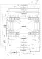
- FIG. 1 schematically shows an exemplary configuration of an imaging device according to a first embodiment of the present disclosure.
- Each of the image pickup apparatus 100A shown in FIG. 1 includes a plurality of pixels Px having a photoelectric conversion unit supported by the semiconductor substrate 110 as a part thereof. That is, in the following, as the image pickup device 100A, an image pickup device having a so-called stacked structure will be illustrated.
- the semiconductor substrate 110 has a plurality of readout circuits formed corresponding to each pixel Px.
- the plurality of pixels Px are arranged two-dimensionally on the semiconductor substrate 110 to form an imaging region.
- the plurality of pixels Px are arranged in a plurality of rows and columns.
- a plurality of pixels Px are arranged in m rows and n columns.
- m and n independently represent an integer of 2 or more.
- the image pickup apparatus 100A has a plurality of line signal lines Ri and a plurality of output signal lines.
- the plurality of line signal lines R i include m line signal lines R 0 , R 1 , R 2 , ..., R m-2 , R m-1 arranged corresponding to a plurality of lines of the pixel Px. ..
- Each of the plurality of row signal lines R i is electrically connected to one or more pixels Px of the same row.
- These row signal lines R i is connected to the row scanning circuit 130.
- the plurality of output signal lines include a plurality of first output signal lines S j and a plurality of second output signal lines T j .
- the plurality of first output signal line S j, the first output signal line S 0 of the n arranged corresponding to the plurality of columns of pixels Px, S 1, S 2, ..., S n-2, S n -1 is included.
- the plurality of second output signal lines T j also have n second output signal lines T 0 , T 1 , T 2 , ..., T n-2 arranged corresponding to the plurality of rows of pixels Px. , T n-1 .
- Each of the plurality of first output signal lines Sj is electrically connected to a read circuit of one or more pixels Px belonging to the same row.
- the first analog-digital conversion circuit 141 and the first digital output interface 161 are connected to the plurality of first output signal lines Sj . From the first digital output interface 161, a signal read from the pixel Px via the first output signal line Sj and subjected to analog-to-digital conversion by the first analog-to-digital conversion circuit 141 is output.
- each of the plurality of second output signal line T j is electrically connected to the readout circuit of one or more pixels Px belonging to the same column.
- Each second output signal line T j is connected to, for example, a plurality of pixels belonging to the same row other than the pixels connected to the first output signal line S j .
- a second analog-to-digital conversion circuit 142 and a second digital output interface 162 are connected to the plurality of second output signal lines Tj . From the second digital output interface 162, via the second output signal line T j read from the pixel Px, second analog - signal subjected to the digital conversion is output - analog by the digital conversion circuit 142.
- the analog-to-digital conversion circuit is simply referred to as the "AD conversion circuit” and the digital output interface is simply referred to as the "interface" below.
- the image pickup apparatus 100A further includes a first digital memory 151 connected between the first AD conversion circuit 141 connected to the first output signal line Sj and the first interface 161.
- the image pickup apparatus 100A also has a second digital memory 152 which is connected between the first 2AD conversion circuit 142 connected to the second output signal line T j and the second interface 162.
- the first digital memory 151 and the second digital memory 152 temporarily transmit one line of digital signals read from a plurality of pixels Px and analog-digitally converted by the first AD conversion circuit 141 or the second AD conversion circuit 142. Hold.
- the result of one line of analog-digital conversion is held in the digital memory, and the AD conversion circuit is used for the analog-related to the next line. It will be possible to perform digital conversion. That is, line-by-line analog-to-digital conversion can be processed at higher speed.
- An image processing circuit 170A is connected to the first interface 161 and the second interface 162.
- the image processing circuit 170A executes processing such as gamma correction, color interpolation processing, spatial interpolation processing, and auto white balance on the digital signal output from the interface, if necessary.
- the image processing circuit 170A can be realized by, for example, a DSP (Digital Signal Processor), an ISP (Image Signal Processor), an FPGA (field-programmable gate array), or the like.
- control circuit 220 is electrically connected to the image processing circuit 170A.
- the image processing circuit 170A provides the control circuit 220 with control signals such as a vertical synchronization signal and a horizontal synchronization signal.
- a row scanning circuit 130, a first AD conversion circuit 141, and a second AD conversion circuit 142 are connected to the control circuit 220.
- the control circuit 220 is implemented by, for example, a microcontroller including one or more processors and typically has a timing generator.
- the control circuit 220 supplies a drive signal to the row scanning circuit 130, the first AD conversion circuit 141, and the second AD conversion circuit 142, and controls the entire image pickup apparatus 100A.
- the arrow extending toward the control circuit 220 and the arrow extending from the control circuit 220 schematically represent an input signal to the control circuit 220 and an output signal from the control circuit 220, respectively.
- the control circuit 220 may include one or more memories.
- the image pickup device 100A may include a display device 180 such as a liquid crystal display or an organic EL display connected to the image processing circuit 170A.
- the display device 180 presents an image based on the digital signal obtained by photographing to the user of the image pickup device 100A.
- the image processing circuit 170A has a first frame memory 171.
- the first frame memory 171 temporarily holds digital data corresponding to one frame of images output from the first interface 161 and / or the second interface 162.
- the first frame memory 171 temporarily holds the first digital signal corresponding to the reset signal expressing the reset level.
- the first digital signal is a digital signal output from the first AD conversion circuit 141 or the second AD conversion circuit 142 by inputting a reset signal which is an analog signal read from each pixel Px.
- the image processing circuit 170A outputs the difference between the first digital signal held in the first frame memory 171 and the second digital signal corresponding to the pixel signal expressing the image of the subject.
- the difference between the digital signals can substantially cancel the effect of random noise due to the reset operation performed immediately before the exposure period.
- the image pickup apparatus 100A includes a first system including the first output signal line S j and a second system including the second output signal line T j with respect to reading a signal from the pixels. It has two systems of.
- the first output signal line Sj is connected to one or more pixels in that row.
- the second output signal line Tj is connected to one or more other pixels in the row.
- the reset signal is read from a certain pixel and the pixel signal is read from a pixel belonging to a row different from the row to which the pixel belongs. Can be executed in parallel. Therefore, since the interval between the read period of the reset signal line by line and the read period of the pixel signal line can be reduced, it is possible to improve the frame rate while removing the influence of the reset noise. ..
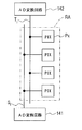
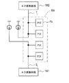
- FIG. 2 shows an exemplary circuit configuration of the image pickup apparatus 100A.
- four pixels Px included in the imaging region shown in FIG. 1 are taken out and schematically shown.
- These four pixels Px include a first pixel Px1, a second pixel Px2, a third pixel Px3, and a fourth pixel Px4 arranged in 2 rows and 2 columns.
- the first pixel Px1 and the second pixel Px2 are located in the same row, while the third pixel Px3 and the fourth pixel Px4 are in the same row different from the first pixel Px1 and the second pixel Px2. Located in.
- the first pixel Px1 and the second pixel Px2 are located in, for example, even rows of a pixel array containing a plurality of pixels Px, and the third pixel Px3 and the fourth pixel Px4 are located in odd rows of the pixel array.
- the basic circuit configuration of the pixels is common among these pixels Px1 to Px4, and therefore, an exemplary configuration of each pixel will be described below with a focus on the first pixel Px1.
- the first pixel Px1 includes a photoelectric conversion unit 10 and a readout circuit 20 electrically connected to the photoelectric conversion unit 10.
- the photoelectric conversion unit 10 has a pixel electrode, a counter electrode, and a photoelectric conversion layer sandwiched between these electrodes.
- the photoelectric conversion unit 10 of each pixel has an electrical connection with a voltage line 192 connected to the voltage supply circuit 190, and a predetermined voltage is applied between the pixel electrode and the counter electrode during the operation of the image pickup apparatus 100A. It is configured to be possible.
- the voltage supply circuit 190 may be configured so that a predetermined voltage can be applied to the photoelectric conversion unit 10 of each pixel when the image pickup apparatus 100A operates, and is not limited to a specific power supply circuit.
- the voltage supply circuit 190 may be a circuit that generates a predetermined voltage, or may be a circuit that converts a voltage supplied from another power source into a predetermined voltage.
- the voltage supply circuit 190 may be a part of the row scanning circuit 130.
- the read circuit 20 includes a signal detection transistor 22, an address transistor 24, and a reset transistor 26.
- the signal detection transistor 22, the address transistor 24, and the reset transistor 26 are typically field effect transistors formed on the semiconductor substrate 110, and an example in which an N-channel MOSFET is used for these transistors will be described below.
- the gate of the signal detection transistor 22 is connected to the pixel electrode of the photoelectric conversion unit 10.
- the source of the signal detection transistor 22 is connected to the corresponding output signal line via the address transistor 24.
- a set of a first output signal line Sj and a second output signal line Tj is arranged for each of a plurality of columns of the plurality of pixels Px.
- the first output signal line Sj is connected to the first AD conversion circuit 141.
- the second output signal line T j is connected to the 2AD conversion circuit 142.
- the source of the signal detection transistor 22 of the first pixel Px1 is electrically connected to the first output signal line Sj . Is connected.
- the source of the signal detection transistor 22 of the fourth pixel Px4 is electrically connected to the second output signal line Tj .
- the source of the signal detection transistor 22 of the second pixel Px2 is electrically connected to the first output signal line S j-1.
- the source of the signal detection transistor 22 of the third pixel Px3 is electrically connected to the second output signal line Tj -1 . That is, in this example, the first AD conversion circuit 141 generates a digital signal corresponding to the analog signal read from, for example, the first pixel Px1 and the second pixel Px2 located in the even rows of the pixel array by analog-digital conversion. , Output to the first interface 161. Further, the second AD conversion circuit 142 generates a digital signal corresponding to an analog signal read from, for example, the third pixel Px3 and the fourth pixel Px4 located in the odd-numbered rows of the pixel array, and outputs the digital signal to the second interface 162.
- the analog signal read from each pixel Px includes a reset signal expressing the reset level and a pixel signal expressing the image of the subject.
- the reset signal and the pixel signal read from each pixel Px are signals on which kTC noise generated by resetting the pixels is superimposed.
- the first AD conversion circuit 141 and the second AD conversion circuit 142 may have a plurality of elements provided for each output signal line, such as a column signal processing circuit 145. Each of these plurality of elements is connected to the corresponding one of the plurality of output signal lines.
- the drain of the signal detection transistor 22 of each pixel is connected to the power supply line 194.
- the power supply line 194 functions as a source follower power supply by applying a power supply voltage VDD of about 3.3 V during operation of the image pickup apparatus 100A.
- a line signal line Ri is connected to the gate of the address transistor 24.
- Row scanning circuit 130 is controlled by the voltage level applied to the row signal lines R i, it switches on and off of the address transistor 24. As a result, the row scanning circuit 130 can read a signal from the pixels belonging to the selected row to the corresponding output signal line.
- the readout circuit 20 includes a reset transistor 26.
- One of the drain and source of the reset transistor 26 is connected to a node FD that electrically connects the photoelectric conversion unit 10 to the gate of the signal detection transistor 22.
- the other of the drain and source of the reset transistor 26 is connected to the reset voltage line 196.
- the reset voltage line 196 is connected to the reset voltage supply circuit 198.
- a predetermined reset voltage VRST is applied from the reset voltage supply circuit 198 to the reset voltage line 196.
- the reset voltage VRST for example, a voltage of 0V or a voltage near 0V is used.
- the reset voltage supply circuit 198 may be configured so that a predetermined reset voltage can be applied to each pixel during the operation of the image pickup apparatus 100A, and is not limited to a specific power supply circuit like the voltage supply circuit 190.
- the reset voltage supply circuit 198 may be a circuit independent of the voltage supply circuit 190, and one of the reset voltage supply circuit 198 and the voltage supply circuit 190 may be a part of the other.
- a plurality of reset signal line Q i are provided corresponding to the plurality of pixels Px. As shown, typically, one reset signal line is commonly connected to the gates of the reset transistors 26 of a plurality of pixels Px belonging to the same row. In this example, the reset signal line Q i has a connection to the row scanning circuit 130.
- the row scanning circuit 130 is controlled by the voltage level applied to the reset signal line Q i, by turning on the reset transistor 26 in a row unit of a plurality of pixels Px, nodes pixel Px reset transistor 26 is turned on The potential of the FD can be reset to VRST .
- FIG. 3 schematically shows the device structure of the first pixel Px1.
- the first pixel Px1 generally includes a semiconductor substrate 110 on which a readout circuit 20 is formed, and a photoelectric conversion unit 10 supported by the semiconductor substrate 110. As shown in FIG. 3, typically, an insulating layer 50 covering the readout circuit 20 is arranged between the semiconductor substrate 110 and the photoelectric conversion unit 10.
- the photoelectric conversion unit 10 includes a pixel electrode 11 supported by the insulating layer 50, a translucent counter electrode 13, and a photoelectric conversion layer 12 located between the pixel electrode 11 and the counter electrode 13.
- the pixel electrode 11 is located closer to the semiconductor substrate 110 than the photoelectric conversion layer 12, and is made of a metal such as aluminum or copper, a metal nitride, or polysilicon that has been imparted with conductivity by being doped with impurities. Can be formed.
- the pixel electrode 11 is electrically separated from the pixel electrodes 11 of other adjacent pixels by being spatially separated from the pixel electrodes 11.
- the counter electrode 13 is located on the side where the light from the subject arrives.
- the counter electrode 13 is a translucent electrode formed of a conductive material such as ITO.
- the term "translucency" in the present specification means that the photoelectric conversion layer 12 transmits at least a part of light having a wavelength that can be absorbed, and transmits light over the entire wavelength range of visible light. Is not required.
- An optical filter such as a color filter, a microlens, or the like may be arranged on the main surface of the counter electrode 13 on the side opposite to the photoelectric conversion layer 12.
- the counter electrode 13 is typically provided in the form of a single continuous electrode layer straddling a plurality of pixels.
- the voltage line 192 described above is connected to the counter electrode 13 of the photoelectric conversion unit 10.
- the voltage line 192 is shown to be connected to each photoelectric conversion unit 10 of a plurality of pixels, but typically, the counter electrode 13 of each pixel is continuous between the plurality of pixels. It is part of a single translucent electrode. Therefore, the counter electrode 13 of each pixel is basically equipotential, and it is not essential that the voltage line 192 is a wiring branched into a plurality of lines.
- the photoelectric conversion layer 12 is formed of an organic material or an inorganic material such as amorphous silicon, and receives light incident through the counter electrode 13 to generate a charge pair. Like the counter electrode 13, the photoelectric conversion layer 12 is typically provided in the form of a single photoelectric conversion structure that is continuous across a plurality of pixels. That is, the photoelectric conversion layer 12 in each pixel can be a part of the photoelectric conversion layer continuously formed over a plurality of pixels.
- the photoelectric conversion layer 12 By forming the photoelectric conversion layer 12 by selecting one or more suitable materials as the photoelectric conversion material, for example, it is possible to obtain the photoelectric conversion layer 12 exhibiting sensitivity in both the visible region and the infrared region. .. Examples of such materials are described in detail in, for example, WO 2018/025544. For reference, the entire disclosure of International Publication No. 2018/025544 is incorporated herein by reference.
- the photoelectric conversion layer 12 may be composed of quantum dots and / or nanotubes. Alternatively, the photoelectric conversion layer 12 may include quantum dots and / or nanotubes as the photoelectric conversion material.
- the photoelectric conversion layer 12 may include a layer made of an organic material and a layer made of an inorganic material.
- the insulating layer 50 located between the semiconductor substrate 110 and the photoelectric conversion unit 10 includes, for example, a plurality of insulating layers each formed of silicon dioxide. As schematically shown in FIG. 3, a multilayer wiring including at least a conductive structure 52 having one end connected to a pixel electrode 11 of a photoelectric conversion unit 10 is provided inside the insulating layer 50.
- the conductive structure 52 may include vias and wiring made of metal such as copper, plugs made of polysilicon, and the like. In the illustrated example, the other end of the conductive structure 52 is electrically connected to the impurity region 111 formed on the semiconductor substrate 110.
- the semiconductor substrate 110 has impurity regions 112, 113, 114 and 115 in addition to the impurity regions 111.
- the semiconductor substrate 110 also has an element separation region 116 that electrically separates the readout circuit 20 provided for each pixel Px between the pixels Px.
- a P-type silicon substrate will be illustrated as the semiconductor substrate 110.
- the semiconductor substrate 110 may be an insulating substrate or the like having a semiconductor layer provided on its surface.
- Each of the impurity regions 111, 112, 113, 114 and 115 is typically an N-type diffusion region.
- the impurity region 111 to which the conductive structure 52 is connected functions as one of the source region and the drain region of the reset transistor 26.
- the reset transistor 26 further includes an impurity region 112 that functions as the other of the source region and the drain region, a gate insulating layer 26 g on the semiconductor substrate 110, and a gate electrode 26e on the gate insulating layer 26 g.
- the reset voltage line 196 described above is connected to the impurity region 112.
- the signal detection transistor 22 includes an impurity region 113 and an impurity region 114, a gate insulating layer 22 g on the semiconductor substrate 110, and a gate electrode 22e on the gate insulating layer 22 g.
- the impurity region 113 functions as a drain region of the signal detection transistor 22, and the impurity region 114 functions as a source region of the signal detection transistor 22.
- the power line 194 described above is connected to the impurity region 113.
- the element separation region 116 is also provided between the signal detection transistor 22 and the reset transistor 26.
- the address transistor 24 includes an impurity region 114 and an impurity region 115, a gate insulating layer 24 g on the semiconductor substrate 110, and a gate electrode 24e on the gate insulating layer 24 g.
- the impurity region 114 and the impurity region 115 function as a drain region and a source region of the address transistor 24, respectively.
- the address transistor 24 shares the impurity region 114 with the signal detection transistor 22.
- the corresponding one of the plurality of output signal lines S j and T j described above is connected to the impurity region 115.
- the insulating layer 50 covers the signal detection transistor 22, the address transistor 24, and the reset transistor 26.
- the conductive structure 52 in the insulating layer 50 also has an electrical connection with the gate electrode 22e of the signal detection transistor 22. That is, the conductive structure 52 in each pixel has a function of electrically connecting the pixel electrode 11 of the photoelectric conversion unit 10 and the readout circuit 20 including the signal detection transistor 22 formed on the semiconductor substrate 110 to each other.
- the conductive structure 52 also has a function as a part of a charge storage region for temporarily storing the electric charge collected by the pixel electrode 11, that is, the signal charge.
- the voltage supply circuit 190 applies a predetermined voltage to the photoelectric conversion unit 10 of each pixel via the voltage line 192.
- a predetermined potential difference ⁇ V can be applied between the counter electrode 13 and the pixel electrode 11 during the exposure period.
- a voltage to the counter electrode 13 so that the potential of the counter electrode 13 is higher than that of the pixel electrode 11 with the pixel electrode 11 as a reference, positive light is generated in the photoelectric conversion layer 12 by the incident light.
- a charge having a positive polarity for example, a hole can be collected by the pixel electrode 11 as a signal charge.
- the signal charge is temporarily stored in the charge storage region including the conductive structure 52 as a part thereof.
- the impurity region 111 formed on the semiconductor substrate 110, the pixel electrode 11 of the photoelectric conversion unit 10, and the gate electrode 22e of the signal detection transistor 22 also have a charge storage region that temporarily stores signal charges. Acts as part of.
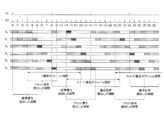
- Example driving method of image pickup apparatus 100A 4 and 5 are diagrams for explaining an example of a method of driving the image pickup apparatus according to the first embodiment of the present disclosure.
- the top chart shows the pulse of the vertical sync signal VD.
- the rising edge of the pulse of the vertical sync signal VD represents the start of a period for reading the pixel signal.
- the second chart from the top in FIG. 4 shows the pulse of the horizontal synchronization signal HD.
- the period from the rise of one pulse to the rise of the next pulse corresponds to one horizontal scanning period of 1H.
- FIG. 4 a plurality of blocks showing the operation of the plurality of pixels Px included in the imaging region are also shown in one figure.
- the number of rows of the plurality of pixel Px is 6 rows of the 0th row R 0 to the 5th row R 5
- the operation of the pixel Px is schematically shown by a plurality of rectangular blocks.
- Row 0 R 0 of a plurality of pixels Px includes, for example, a first pixel Px1 and the second pixel Px2 described above
- the first row R 1 includes, for example, a third pixel Px3 and the fourth pixel Px4 above.
- the white rectangular block schematically represents the exposure period of the frame period
- the rectangular block hatched by vertical lines is the reading of the reset level corresponding to the signal level in the dark. Represents a period.
- the rectangular block with hatching by diagonal lines represents the period for reading the pixel signal representing the image of the subject.
- the driving method of the image pickup apparatus illustrated in FIG. 5 is roughly a step of resetting the potential of the charge storage region of the pixel (step S1) and a reset according to the potential of the charge storage region after resetting the pixel.
- a step of reading a signal step S2
- a step of generating a first digital signal corresponding to a reset signal by analog-digital conversion step S3
- a step of storing the first digital signal in a frame memory step S4.
- step S6 A step of reading a signal (step S6), a step of generating a second digital signal corresponding to a pixel signal by analog-digital conversion (step S7), and a step of obtaining a difference between the second digital signal and the first digital signal (step S7).
- step S8 A step of reading a signal (step S6), a step of generating a second digital signal corresponding to a pixel signal by analog-digital conversion (step S7), and a step of obtaining a difference between the second digital signal and the first digital signal (step S7).
- step S8 details of an exemplary driving method of the imaging device will be described with reference to FIG.
- FIG. 4 shows an example of an operation based on a so-called rolling shutter, which executes exposure and signal reading for each row of a plurality of pixels.
- first attention is paid to the 0th row R 0 of row 0 R 0 ⁇ fifth row R 5.
- the charge storage area of each pixel Px is reset.
- k is an integer of 0 or more
- the reset of a plurality of pixels belonging to the 0th row R0 is started at time t3 with respect to the kth frame period.
- the signal detection transistor 22 of the readout circuit 20 has a pixel electrode 11 due to the gate electrode 22e being electrically connected to the pixel electrode 11 via the conductive structure 52. Outputs a signal according to the potential. That is, the readout circuit 20 outputs an analog signal corresponding to the potential of the pixel electrode 11 by the source follower including the signal detection transistor 22.
- ⁇ Process of reading the reset signal> After turning off the reset transistor 26, by turning on the address transistor 24, a signal corresponding to a reset voltage V RST applied to the gate electrode 22e of the signal detection transistor 22 is output to the corresponding output signal line ..
- the signal output to the output signal line at this time is an analog signal expressing the reset level, and usually includes reset noise generated when the reset transistor 26 is turned off.
- the reset signal read from the pixel belonging to the 0th line R0 is passed through the corresponding one of the first output signal lines Sj. It is input to the first AD conversion circuit 141.
- the reset signal input to the first AD conversion circuit 141 is converted into a digital signal by the first AD conversion circuit 141.
- the address transistor 24 is turned off.
- the reading of the reset signal from the pixel belonging to the 0th row R0 is completed.
- the above-mentioned reading operation is sequentially executed line by line in synchronization with the horizontal synchronization signal HD.
- the pulse interval of the horizontal synchronization signal HD that is, the 1H period represents the period from the selection of one line to the selection of the next line.
- the pixel belonging to the 0th row R0 is reset and the reset signal is read from the pixel during the period from time t3 to time t4, and the first is executed during the period from time t4 to time t5. running a read reset signal from the reset and the pixels of the pixel belonging to row R 1.
- the reset level read period may include a reset period for resetting the potential in the charge storage region of the pixel.
- the reset signals read from the pixels belonging to the first row R 1 is the first output signal line S j without the second output signal line T It is input to the second AD conversion circuit 142 via the corresponding one of j . That is, here, the reset signal read from the pixels located in the even-numbered rows and the reset signal read from the pixels located in the odd-numbered rows are passed through different output signal lines to the first AD conversion circuit 141. And is input to any of the second AD conversion circuits 142. The reset signal input to the second AD conversion circuit 142 is also converted into a digital signal by analog-digital conversion.
- the digital signals output from the first AD conversion circuit 141 and the second AD conversion circuit 142 are input to the image processing circuit 170A via the first interface 161 and the second interface 162, respectively.
- the first digital signal corresponding to the reset signal read between the time t3 and the time t9 in FIG. 4 is temporarily held in the first frame memory 171 in the image processing circuit 170A.
- the reset transistor 26 After reading the reset signal, the reset transistor 26 is turned off and the exposure period is started.
- the period from the time t4 to the time t8 is the exposure period in the kth frame period.
- the exposure period is a period for accumulating the signal charge generated by the photoelectric conversion unit 10 according to the exposure amount to the pixel in the charge storage region.
- the length of the exposure period of each row of the plurality of pixels Px is, for example, in the range of 1/60 seconds to 1/16000 seconds.
- the counter electrode 13 of the photoelectric conversion unit 10 of each pixel Px receives a predetermined voltage V1 from the voltage supply circuit 190 via the voltage line 192, so that the pixel electrode 11 is in a high potential state, for example. It is said that.
- the potential of the pixel electrode 11 immediately after the reset is determined by the above-mentioned reset voltage VRST , and immediately after the reset, a bias voltage of (V1-V RST ) is applied between the pixel electrode 11 and the counter electrode 13. is there.
- the positive charge of the charge pairs generated by the photoelectric conversion is collected by the pixel electrode 11.
- the PN junction formed in the semiconductor substrate 110 by forming the impurity region 111 functions as a junction capacitance for temporarily accumulating the positive charges collected by the pixel electrodes 11.
- the potential of the impurity region 111 as the charge storage portion rises as the signal charge accumulates in the impurity region 111.
- (V1-V RST )>0 but for example, a voltage is applied to the counter electrode 13 so that the potential of the counter electrode 13 is lower than that of the pixel electrode 11. Therefore, for example, it is also possible to use electrons as signal charges.
- the pixel signal is read out.
- the reading of the signal from the pixel belonging to the 0th row R0 is started at time t8 based on the vertical synchronization signal VD.
- the read-out circuit 20 of each pixel belonging to the 0th row R0 outputs an analog signal corresponding to the potential of the pixel electrode 11 to the corresponding one of the plurality of first output signal lines.
- Signal read from the pixel of row 0 R 0 at this time is an analog signal corresponding to the charge amount accumulated in the charge accumulation region in the exposure period for the 0th row R 0, based on ambient light such as sunlight It is a pixel signal that expresses an image of a subject. This pixel signal contains reset noise caused by a reset operation performed before the exposure period. After reading the pixel signal, the address transistor 24 is turned off again.
- the pixel signal read from the pixels of the 0th line R 0 , the 2nd line R 2 and the 4th line R 4 is the first output signal line S j . It is sent to the 1AD conversion circuit 141.
- the first row R 1, the third row R 3, pixel signals read from the pixels of the fifth row R 5 is sent to the 2AD conversion circuit 142 via the second output signal line T j.
- the first AD conversion circuit 141 and the second AD conversion circuit 142 perform analog-digital conversion on a line-by-line basis for the received pixel signal, and generate a second digital signal corresponding to the pixel signal.
- the generated second digital signal is sent to the image processing circuit 170A via the first interface 161 or the second interface 162.
- the image processing circuit 170A calculates the difference between the second digital signal corresponding to the pixel signal and the first digital signal corresponding to the reset signal, and outputs this difference as pixel value data.
- the reset signal read from the pixel after resetting the potential in the charge storage region is superposed with the reset noise generated by the reset. Further, the reset signal is read in a non-destructive manner, and the potential of the charge storage region is not reset again in the period until the pixel signal is read. Therefore, the pixel signal corresponding to the amount of charge accumulated in the charge accumulation region during the exposure period is also in a state in which reset noise is superimposed.
- the difference between these digital signals is obtained. Therefore, by subtracting the first digital signal corresponding to the reset signal, the reset noise is substantially subtracted from the second digital signal corresponding to the pixel signal, and as a result, the influence of the reset noise is effectively canceled. To.
- FIG. 4 is a schematic of the 1H period from the time t8 shown in FIG. 4 to time t9, the operation of the readout circuit 20 of the 0th row pixel of R 0, and the operation of the readout circuit of a pixel in the fifth row R 5 Shown in.
- FIG. 4 is a schematic of the 1H period from the time t8 shown in FIG. 4 to time t9, the operation of the readout circuit 20 of the 0th row pixel of R 0, and the operation of the readout circuit of a pixel in the fifth row R 5 Shown in.
- the graph of ⁇ S represents the waveform of the address control signal applied to the gate of the address transistor 24 of the read circuit 20, and the graph of ⁇ R is applied to the gate of the reset transistor 26 of the read circuit 20. It represents the waveform of the reset control signal.
- the graph of V 0 schematically shows the period during which the signal read from the pixel of row 0 R 0 is analog-digitally converted by the first AD conversion circuit 141. In other words, it represents the output waveform from the first AD conversion circuit 141.
- the graph of V 5 schematically shows the period during which the signal read from the pixel of row 5 R 5 is analog-digitally converted by the second AD conversion circuit 142. In other words, it represents the output waveform from the second AD conversion circuit 142.
- the timing of the output of the second digital signal corresponding to the pixel signal is the same.
- the result of one line of analog-digital conversion of the plurality of pixels Px may be output at a common timing between the first AD conversion circuit 141 and the second AD conversion circuit 142.
- the output of the result of the analog-to-digital conversion matches between the first AD conversion circuit 141 and the second AD conversion circuit 142.
- FIG. 7 schematically shows the operation of the readout circuit 20 with respect to the pixels in the hth row and the kth row, which are different from each other in the pixel array.
- a first output signal line and a second output signal line are provided for each row of a plurality of pixels Px, and a part of the plurality of pixels Px is used.
- reading of the reset signal from one pixel and reading of the pixel signal from another pixel are executed in parallel. Will be possible.
- a part of the reset signal read period and the pixel signal read are performed. It becomes possible to overlap a part of the period, and the length of the exposure period can be flexibly changed. For example, the exposure period can be shortened to improve the frame rate.
- the 2AD conversion circuit 142 is separated and arranged.
- the arrangement of the first AD conversion circuit 141 and the second AD conversion circuit 142 is not limited to this example.
- the first AD conversion circuit 141 and the second AD conversion circuit 142 may be arranged in the vicinity of one side of the imaging region RA having a substantially rectangular shape.
- first AD conversion circuit 141 and the second AD conversion circuit 142 need not be formed on the semiconductor substrate 110 provided with the plurality of pixels Px.
- a first AD conversion circuit 141, a second AD conversion circuit 142, a first digital memory 151, a second digital memory 152, and an image processing circuit are placed on another circuit board 120 different from the semiconductor board 110.
- a configuration such as arranging 170A or the like is also possible.
- the pixels located in the even-numbered rows and the pixels located in the odd-numbered rows of the plurality of pixels Px are connected to the first output signal line Sj and the second output signal line Tj , respectively.
- the connection of the pixels to the first output signal line S j and the second output signal line T j is not limited to these modes.
- 11 and 12 schematically show other examples of pixel connections to output signal lines. Configuration shown in FIG. 11 is an example of connecting alternately the pixels in every two rows of a plurality of pixels Px to the first output signal line S j and the second output signal line T j.
- FIG. 12 shows four output signal lines, a first output signal line S j , a second output signal line T j , a third output signal line U j, and a fourth output signal line V j , for each row of a plurality of pixels Px.
- the first output signal line S j , the second output signal line T j , the third output signal line U j, and the fourth output signal line V j are combined with the first AD conversion circuit 141 and the second AD conversion circuit 142.
- the third AD conversion circuit 143 and the fourth AD conversion circuit 144 are connected, respectively.
- a part of the plurality of pixels Px is connected to the first output signal line Sj connected to the first AD conversion circuit 141, and the other part is connected to the first output signal line Sj . It may be connected to the second output signal line T j that is connected to the 2AD conversion circuit 142.
- the imaging region RA is divided into two regions, and the pixel connection destination is either the first AD conversion circuit 141 or the second AD conversion circuit 142 depending on which region it belongs to. You may decide.
- the imaging region RA is divided into two regions, upper and lower.
- the pixels located in the lower half region of the imaging region RA are connected to the first output signal line Sj connected to the first AD conversion circuit 141.
- pixels positioned in the upper half region of the imaging region RA is connected to the second output signal line T j that is connected to the 2AD conversion circuit 142.
- Pixel signal reading can be performed line by line. That is, the overlap between the read-out period of the reset signal for some pixels and the read-out period of the pixel signal for some other pixels is allowed, and for example, the effect of shortening the frame rate can be obtained.
- the first AD conversion circuit 141 and the second AD conversion circuit 142 corresponds to the reset signal read from that pixel. Both the first digital signal to be generated and the second digital signal corresponding to the pixel signal are generated. However, as described below, the first AD conversion circuit converts the digital signal corresponding to the analog signal read from the pixel into a digital signal depending on whether the analog signal read from the pixel is a reset signal or a pixel signal. You may switch whether to output from 141 or the second AD conversion circuit 142.
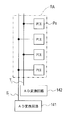
- FIG. 14 shows a modified example of the image pickup apparatus according to the first embodiment of the present disclosure.
- a first AD conversion circuit 141 In order to avoid the drawing from becoming excessively complicated, in FIG. 14, four pixels belonging to a certain row are taken out and shown among a plurality of pixels Px, and in FIG. 14, an image processing circuit is shown.
- the illustration of elements common to the image pickup apparatus 100A, such as 170A, is omitted.
- the first signal A switching circuit 31 is interposed between the first output signal line S j and the second output signal line T j corresponding to the column that belongs the pixel.
- the first signal switching circuit 31 may be a part of each pixel.
- the pixel is the first output signal line Sj , depending on whether the analog signal read from the pixel is a reset signal or a pixel signal. And which of the second output signal line Tj is connected is switched. For example, when the output from the pixel read circuit 20 is a reset signal, the first signal switching circuit 31 establishes a connection between the pixel read circuit 20 and the first output signal line Sj, and the pixel When the output from the reading circuit 20 of the above is a pixel signal, the connection between the reading circuit 20 of the pixel and the second output signal line Tj is established.
- the first signal switching circuit 31 can be realized in the form of a circuit including a switching element such as a field effect transistor formed on the semiconductor substrate 110, for example. These switching elements are operated in synchronization with the pixel reading circuit 20 based on, for example, the drive signal Ds from the control circuit 220. As a result, the first signal switching circuit 31 establishes a connection between the read circuit 20 and the first output signal line Sj when the reset signal is output from the read circuit 20, and the pixel signal from the read circuit 20 is input. At the time of output, the connection between the read circuit 20 and the second output signal line Tj can be established.
- the 1AD conversion circuit 141 connected to the first output signal line S j is an analog reset signal read from each pixel - responsible for digital conversion, the second output signal line T j
- the connected second AD conversion circuit 142 is responsible for analog-to-digital conversion of the pixel signal read from each pixel.
- the AD conversion circuit that outputs the first digital signal and the AD conversion circuit that outputs the second digital signal may be provided in the image pickup apparatus. Even with such a configuration, it is possible to read a pixel signal from a pixel in another row in parallel with reading a reset signal from a pixel in a certain row in the imaging region RA.
- the period for reading the reset signal and the period for reading the pixel signal can be overlapped, and the frame rate can be flexibly changed. Further, by calculating the difference between the first digital signal held in the first frame memory 171 and the second digital signal corresponding to the first digital signal by the image processing circuit 170A, it is mixed in these signals. The reset noise that has been generated can be effectively canceled. As described with reference to FIGS. 6 and 7, the timing of the output of the first digital signal from the first AD conversion circuit 141 and the timing of the output of the second digital signal from the second AD conversion circuit 142 are , May match or may be out of alignment.
- FIG. 15 shows another modification of the imaging device according to the first embodiment of the present disclosure.
- the image pickup apparatus 100C shown in FIG. 15 some of the pixels belonging to the same row in the imaging region RA are connected to the first output signal line Sj . It is connected and the remaining pixels are connected to the second output signal line Tj .
- the first signal switching circuit 31 is not disposed.
- the first signal switching circuit 33 is connected between the set of the first output signal line S j and the second output signal line T j and the first AD conversion circuit 141, and the first output signal line S j is also connected. and the second signal switching circuit 34 is connected between the second output signal line T j of the set and the 2AD conversion circuit 142.
- the first signal switching circuit 33 and the second signal switching circuit 34 switch the connection of the output signal line between the AD conversion circuit and the source follower power supply, for example, based on the drive signal Dt from the control circuit 220.
- each of the first signal switching circuit 33 and the second signal switching circuit 34 may be configured to operate in the same manner as the four-way switch. However, these operations are complementary between the first signal switching circuit 33 and the second signal switching circuit 34.
- “the first signal switching circuit 33 and the second signal switching circuit 34 operate complementarily” means that one of the first signal switching circuit 33 and the second signal switching circuit 34 operates the first output signal line Sj.
- the other of the first signal switching circuit 33 and the second signal switching circuit 34 connects the output signal line and the source follower power supply. It means establishing a connection between them.
- the first signal switching circuit 33 establishes a connection between the first output signal line Sj and the first AD conversion circuit 141
- the second signal switching circuit 34 has the first output signal line Sj and the source follower power supply. Establish a connection with.
- the first signal switching circuit 33 is in a state of establishing the connection between the second output signal line Tj and the source follower power supply, and the second signal switching circuit 34 is in the second output signal line T.
- the connection between j and the second AD conversion circuit 142 has been established.
- the first AD conversion circuit 141 when the first AD conversion circuit 141 is connected to the first pixel via the first output signal line Sj to perform analog-to-digital conversion of the reset signal output from the first pixel, for example, the first 2AD conversion circuit 142, by being connected to the second pixel with the other via the second output signal line T j, analog pixel signals output from the second pixel - concurrently executing digital conversion.
- the connections in the first signal switching circuit 33 and the second signal switching circuit 34 are switched as schematically shown by the dotted lines in FIG.
- the 1AD conversion circuit 141 an analog of the output reset signal from the second pixel by being connected to the second pixel through the second output signal line T j - can perform digital conversion,
- the second AD conversion circuit 142 By connecting the second AD conversion circuit 142 to the first pixel via the first output signal line Sj , the analog-to-digital conversion of the pixel signal output from the first pixel can be executed in parallel. ..
- one of the first AD conversion circuit 141 and the second AD conversion circuit 142 is responsible for analog-to-digital conversion of the reset signal read from each pixel, and the first AD conversion circuit 141 and the second AD conversion.
- the other side of the circuit 142 is responsible for analog-to-digital conversion of the pixel signal read from each pixel.
- the pixels located in the even-numbered lines of the imaging region RA are connected to the first output signal line Sj
- the pixels located in the odd-numbered lines of the imaging region RA are connected to the second output signal line Tj . You are connected.
- connection of pixels to the output signal line is not limited to this example, and a part of the plurality of pixels Px is connected to the first output signal line S j , and the remaining pixels are connected to the second output signal line T j. It suffices if it is connected to.
- FIG. 16 schematically shows an exemplary configuration of an imaging device according to a second embodiment of the present disclosure.
- the image pickup apparatus 100D shown in FIG. 16 has an image processing circuit 170B instead of the image processing circuit 170A.
- the image processing circuit 170B has a second frame memory 172 in addition to the first frame memory 171.
- the first frame memory 171 temporarily holds the first digital signal generated from the reset signal expressing the reset level
- the second frame memory 172 is, for example, from the pixel signal expressing the image of the subject. Temporarily hold the generated second digital signal.
- the image processing circuit 170B calculates the difference between the second digital signal held in the second frame memory 172 and corresponding to the image data of one frame and the first digital signal held in the first frame memory 171. And output.
- a second frame memory 172 that temporarily holds a second digital signal for one frame in the image pickup apparatus in addition to the first frame memory 171, for example, pixels acquired in the next frame period. It is also possible to obtain a difference between the digital signal corresponding to the signal and the second digital signal held in the second frame memory 172.
- the digital signal corresponding to the reset signal for a certain frame period is temporarily held in the first frame memory 171 and the digital signal corresponding to the reset signal for the next frame period is temporarily held in the second frame memory 172. It also becomes possible.
- FIG. 17 shows a modified example of the image pickup apparatus according to the second embodiment of the present disclosure.
- each pixel Px shown in FIG. 17 has a connection similar to that shown in FIG. That is, each pixel Px of the image pickup apparatus 100E shown in FIG. 17, first to the second output signal line T j that is connected to the first output signal line S j and the 2AD conversion circuit 142 connected to the 1AD conversion circuit 141 It is electrically connected via the one-signal switching circuit 31.
- the first output signal line S j outputs a reset signal read from the read circuit 20 of the pixel, while the second output signal line T j ,
- the pixel signal read from the pixel reading circuit 20 is output. That is, the first AD conversion circuit 141 outputs the first digital signal to the first interface 161 and the second AD conversion circuit 142 outputs the second digital signal to the second interface 162. Therefore, in the example shown in FIG. 17, the first interface 161 and the second interface 162 function as output ports for the first digital signal and the second digital signal, respectively.
- the first digital signal output from the first interface 161 is stored in the first frame memory 171.
- the second digital signal output from the second interface 162 is stored in the second frame memory 172. Therefore, among the digital signals corresponding to the outputs from each pixel, the first digital signal can be stored in the first frame memory 171 and the second digital signal can be stored in the second frame memory 172.
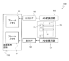
- FIG. 18 shows another modification of the imaging device according to the second embodiment of the present disclosure.
- the image pickup apparatus 100F shown in FIG. 18 in addition to the image pickup region RA including a plurality of pixels Px and the image processing circuit 170B, the first AD conversion circuit 141 and the second AD conversion circuit 142, the first frame memory 171 and the second frame memory It has a data selector 35 electrically connected to and from 172.
- the pixels Px of the image pickup apparatus 100F have the same connections as those shown in FIG. That is, the pixels located in the even-numbered rows of the imaging region RA are connected to the first AD conversion circuit 141 via the first output signal line Sj , while the pixels located in the odd-numbered rows of the imaging region RA are the first. via a second output signal line T j is connected to the second 2AD conversion circuit 142. Therefore, for example, from the first AD conversion circuit 141, the first digital signal and the second digital signal related to the pixels located in the even rows of the imaging region RA are output to the data selector 35.
- the data selector 35 selectively outputs the first digital signal to the first interface 161 among the signals received from the first AD conversion circuit 141.
- the first digital signal relating to the pixels located in the even rows of the imaging region RA is stored in the first frame memory 171.
- the data selector 35 selectively outputs the second digital signal to the second interface 162 among the signals received from the first AD conversion circuit 141. That is, the second digital signal relating to the pixels located in the odd-numbered rows of the imaging region RA is stored in the second frame memory 172.
- the data selector 35 selectively outputs the first digital signal to the first interface 161 and selectively outputs the second digital signal to the second interface 162 among the signals received from the second AD conversion circuit 142. Output. That is, here, the first interface 161 and the second interface 162 function as output ports for the first digital signal and the second digital signal, respectively.
- the data selector 35 determines whether the inputs from the first AD conversion circuit 141 and the second AD conversion circuit 142 are the first digital signal corresponding to the reset signal or the second digital signal corresponding to the pixel signal. Correspondingly, the signals from these AD conversion circuits are output to either the first interface 161 or the second interface 162. As a result, the first digital signal and the second digital signal can be sorted, the first digital signal can be stored in the first frame memory 171 and the second digital signal can be stored in the second frame memory 172.
- the operation according to whether the signal received from the first AD conversion circuit 141 is the first digital signal or the second digital signal is, for example, the first AD conversion circuit 141 and the second AD based on the drive signal from the control circuit 220. This is possible by operating the data selector 35 in synchronization with the conversion circuit 142.
- FIG. 19 shows still another modification of the imaging device according to the second embodiment of the present disclosure.
- the data selector 35 has the first interface 161 and the second interface 162, and the first frame memory 171 and the second frame memory 172. It is electrically connected between them. Similar to the example described with reference to FIG. 18, in this example as well, the first digital signal and the second digital signal output from the first AD conversion circuit 141 and the second AD conversion circuit 142 by the data selector 35 are respectively. It is input to the first frame memory 171 and the second frame memory 172.
- the second digital signal can be output in parallel from the second AD conversion circuit 142, and when the second digital signal is output from the first AD conversion circuit 141. , The first digital signal can be output in parallel from the second AD conversion circuit 142.
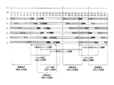
- FIG. 20 shows an example of the operation of the image pickup apparatus having the first frame memory 171 and the second frame memory 172.
- FIG. 20 schematically shows the operation in each of the kth, (k + 1) th, and (k + 2) th frame periods.
- k-th frame period from the time t6 which is the start of the reading of the row 0 pixel related reset signal R 0, is the completion of the reading of the pixel signals relating to pixels of the fifth row R 5 It is a period up to time t14, and its length is eight times as long as the 1H period. Of these, the pixel signal reading period starts at time t8 and ends at time t14 based on the rise of the VD pulse.
- a part of the reset signal reading period and a part of the pixel signal reading period overlap.
- the first digital signal obtained by analog-digital conversion of the read reset signal is temporarily held in the first frame memory 171 and obtained by analog-digital conversion of the read pixel signal.
- the second digital signal is temporarily held in the second frame memory 172.
- the storage of the first digital signal and the second digital signal in the frame memory can be executed in line units. Therefore, while allowing a part of the reset signal reading period and a part of the pixel signal reading period to overlap, for example, the reset signal reading and the pixel signal reading for all the rows of the plurality of pixel Px can be performed. After completion, the difference between the first digital signal and the second digital signal can be executed. Therefore, it is advantageous for shortening the exposure period. According to this embodiment, for example, the exposure period can be shorter than the 1V period.
- the length of the (k + 1) th frame period is 10 times that of the 1H period, whereas the kth frame period has eight times the length of the 1H period, and the (k + 2) th frame period.
- the length of the frame period is 12 times that of the 1H period.
- the readout of the reset signal of each line can be shifted backward to twice the 1H period to shorten the exposure period for the (k + 1) th and (k + 2) th frame periods.
- the shortening of the exposure period is useful for shooting when the environment suddenly shifts from a dark environment to a bright environment.
- the exposure period when the exposure period is extended, the period for reading the reset signal for the previous frame period and the period for reading the reset signal for the later frame period overlap between two consecutive frame periods. It can happen. In this case, regarding the reading of the reset signal in one of the two frame periods, it may not be possible to properly read the reset signal for some lines. Therefore, regarding the extension of the exposure period, the range in which the exposure period can be extended may be set in advance so that the reset signal reading period does not overlap between the two consecutive frame periods. ..
- the reset signal for a pixel in a certain row and the pixel signal for another row in the previous frame period are read, and later. Overlapping with the reading of the reset signal for pixels in yet another row during the frame period of. In such a case, it may not be possible to obtain a reset signal for some rows of a plurality of pixels in either the earlier frame period or the later frame period.
- the acquisition of the reset signal for the previous frame period may be prioritized.
- the pixel signal read from the line where the signal reading period overlaps may be treated as invalid data.
- the reset level acquired for the earlier frame period may be used again for the later frame period.
- the acquisition of the reset signal for the later frame period is prioritized, the pixel signal read from the line where the signal reading period overlaps with respect to the earlier frame period is treated as invalid data or the first.
- the reset level acquired for the frame period immediately before the frame period of is used.
- FIG. 22 schematically shows an example of a signal reading operation in a configuration in which three or more AD conversion circuits are arranged for each row of a plurality of pixels Px.
- the operation shown in FIG. 22 applies, for example, a connection between a pixel and an AD conversion circuit as shown in FIG. 12 to an image pickup apparatus having two frame memories as in the example described with reference to FIG. It is possible under the above configuration.
- a part of the k-th frame period and a part of the (k + 1) -th frame period overlap. Focusing on 1H period for example from time t9 to time t10 in the example shown in FIG. 21, pixels from the k-th reading the first row R 1 of the pixels of the reset signal from the third row R 3 pixels for a frame period The reading of the reset signal from the pixel of the 0th row R0 with respect to the (k + 1) th frame period overlaps with the reading of the signal.
- the pixel of row 0 R 0, the pixel of the first row R 1, the second row R 2 of the pixel, and the third row pixel first output signal each of R 3 1st AD conversion circuit 141, 2nd AD conversion circuit 142, 3rd AD conversion circuit 143 and 4th AD via line S j , 2nd output signal line T j , 3rd output signal line U j and 4th output signal line V j . It is assumed that it is connected to the conversion circuit 144.
- the related (k + 1) th frame period in addition to the pixel signal from the reset signal and the first row of pixels R 1 from the third row R 3 pixels for the k-th frame period, the related (k + 1) th frame period
- the reset signal from the pixel of line 0 R 0 can be read out in parallel via different output signal lines. That is, analog signals can be read out in parallel from three or more rows of a plurality of pixels.
- the analog signals individually read via the first output signal line S j , the second output signal line T j, and the fourth output signal line V j are the first AD conversion circuit 141, the second AD conversion circuit 142, and the fourth AD. It is converted into a digital signal by the conversion circuit 144.
- the digital signals generated by the analog-to-digital conversion for example, the first digital signal corresponding to the reset signal is stored in the first frame memory 171 and the second digital signal corresponding to the pixel signal is the second frame memory. It is stored in 172.
- a data selector 35 is connected to the front stage of the first frame memory 171 and the second frame memory 172 as described with reference to FIGS. 18 and 19. It is possible by doing so.
- FIG. 22 schematically shows still another modification of the imaging device.
- the image pickup apparatus 100H shown in FIG. 22 has an image processing circuit 170B like the imaging apparatus 100D described with reference to FIG. 16, and further has a frequency multiplier 175 connected to the image processing circuit 170B. ..
- the imaging device 100H has no, does not have a second output signal line T j, therefore, the 2AD conversion circuit 142, also including a second interface 162.
- the image processing circuit 170A may be applied instead of the image processing circuit 170B.
- the image pickup apparatus 100H has a plurality of first output signal lines Sj provided corresponding to a plurality of rows of the plurality of pixels Px.
- a readout circuit 20 for two or more pixels belonging to the same row in the imaging region is connected to each of the plurality of first output signal lines Sj .
- the point that a plurality of first output signal lines Sj are connected to the first AD conversion circuit 141 is the same as the examples described so far.
- the frequency multiplier 175 receives the horizontal synchronization signal from the image processing circuit 170B as an input, and generates a pulse train having a period shorter than that of the horizontal synchronization signal. This pulse train has an interval obtained by equally dividing the interval between the pulses of the horizontal synchronization signal, and is sent from the frequency multiplier 175 to the control circuit 220.
- the frequency multiplier 175 is typically a circuit that executes frequency multiplication using a PLL (phase locked loop).
- the frequency multiplier 175 may be a part of the image processing circuit 170B or 170A, or may be a part of the row scanning circuit 130.
- FIG. 23 schematically shows an example of the operation of the image pickup apparatus 100H shown in FIG. 22.
- the third chart from the top schematically shows the pulse of the signal MD output from the frequency multiplier 175.
- the pulse of the signal MD has a period (1/2) times that of the pulse of the horizontal synchronization signal HD.
- a part of the reset signal read-out period and a part of the pixel signal read-out period overlap.
- the pixel signal is read from the pixel of the 0th row R0 in the first half of this 1H period, and the second half of this 1H period is the second.
- Reading of the reset signal from the pixels of line 2 R 2 is being executed. That is, the reading of the pixel signal from the pixel of a certain row belonging to the same column of the plurality of pixels Px and the reading of the reset signal from the pixel of another row are executed within the same 1H period.
- the read reset signal and pixel signal are converted into a first digital signal and a second digital signal by the first AD conversion circuit 141, respectively. Of these, at least the first digital signal is held in the first frame memory 171. At this time, the second digital signal may be held in the second frame memory 172.
- the image processing circuit 170B outputs the difference between the second digital signal and the first digital signal held in the first frame memory 171 for each pixel after the reading of the pixel signals for all the rows is completed. By this difference processing, the influence of the reset noise superimposed on these signals can be substantially canceled.
- a second pulse train having a frequency higher than that of the horizontal sync signal HD pulse may be generated, and the analog signal may be read from the pixels based on the second pulse train.
- the reset noise can be reduced without providing two or more output signal lines in each row of the plurality of pixels Px, as in each of the above examples. The effect of being able to flexibly change the frame rate while canceling the effect can be obtained.
- the reading of the reset signal for a certain frame period precedes the reading of the pixel signal in the frame period immediately before the frame period. Can be done. Therefore, the blanking period between the two frame periods can be shortened and the frame rate can be shortened while the circuit configuration is simpler.
- the image pickup apparatus 100H shown in FIG. 22 has an image processing circuit 170B including a first frame memory 171 and a second frame memory 172.
- the above-mentioned data selector 35 may be interposed between the first interface 161 and the image processing circuit 170B.
- an interface that selectively outputs the first digital signal and an interface that selectively outputs the second digital signal are provided, and a data selector 35 is interposed between these interfaces and the first AD conversion circuit 141. You may.
- the reset signal and the pixel signal for a certain pixel in the imaging region can be sequentially converted into a digital signal. Further, by storing the first digital signal corresponding to the reset signal in the frame memory and calculating the difference from the second digital signal corresponding to the pixel signal, the frame rate is shortened and the influence of the reset noise is affected. It is possible to achieve both substantial cancellation.
- the row scanning circuit 130, the control circuit 220, the first AD conversion circuit 141, the second AD conversion circuit 142, the first digital memory 151, the second digital memory 152, the first interface 161 and the second interface 162 illustrates a configuration arranged on a semiconductor substrate 110 on which a plurality of pixels Px are formed. That is, the semiconductor substrate 110 on which a plurality of pixels Px are formed, the row scanning circuit 130, the control circuit 220, the first AD conversion circuit 141, the second AD conversion circuit 142, the first digital memory 151, the second digital memory 152, and the first interface.
- the 161 and the second interface 162 may be provided in the form of a package in which they are integrated.
- a part or all of these circuits may be integrally formed on the semiconductor substrate 110 in addition to the reading circuit 20 of each pixel Px. That is, these circuits can be formed on the semiconductor substrate 110 by applying the same process as the process of forming the reading circuit 20 for each pixel Px.
- the control circuit 220 may be an integrated circuit formed on the semiconductor substrate 110. However, it is not essential that all of these circuits are integrally formed on the semiconductor substrate 110 together with each pixel Px. A part or all of these circuits may be arranged on a substrate different from the semiconductor substrate 110 on which each pixel Px is formed.
- control circuit 220 receives the setting related to the exposure time from the image processing circuits 170A and 170B according to the processing result of the image processing circuits 170A and 170B, and receives the drive signal according to the setting related to the exposure time from the row scanning circuit 130 and the first AD conversion. It may be configured to supply to the circuit 141, the second AD conversion circuit 142, and the like.
- the image processing circuits 170A and 170B may be provided in the image pickup apparatus in the form of a chip or a package separate from the circuit group arranged on the semiconductor substrate 110. These substrates, including the semiconductor substrate 110, may be provided in a laminated form.
- the first frame memory 171 and / or the second frame memory 172 may be arranged in the image pickup apparatus in the form of a chip or package separate from the image processing circuit 170A or 170B.
- the image processing circuits 170A and 170B may be arranged on the semiconductor substrate 110.
- the image processing circuits 170A and 170B may be a part of the control circuit 220.
- the image processing circuits 170A, 170B or the control circuit 220 may be configured to perform processing such as distance measurement calculation and wavelength information separation.
- the image pickup apparatus may be provided in the form of a package in which a semiconductor substrate 110 on which a plurality of pixels Px are formed and an image processing circuit 170A or 170B are integrated.
- the image pickup apparatus according to the embodiment of the present disclosure may be in the form of an image sensor chip or in the form of a camera.
- Embodiments of the present disclosure include, for example, digital still cameras, digital video cameras, medical cameras, security cameras, cameras mounted on vehicles, ranging cameras, microscope cameras, unmanned aircraft cameras called drones, and robots. It can be used for various cameras such as cameras and camera systems.
- the vehicle-mounted camera can be used, for example, as an input to a control device for the vehicle to travel safely. Alternatively, it can be used to assist the operator in driving the vehicle safely.
- Photoelectric conversion unit 20 Read circuit 31, 33 First signal switching circuit 34 Second signal switching circuit 35 Data selector 100A to 100H Imaging device 110
- Semiconductor board 120 Circuit board 130 line scanning circuit 141 First AD conversion circuit 142 Second AD conversion circuit 143 3rd AD conversion circuit 144 4th AD conversion circuit 145
- Column signal processing circuit 161 1st interface 162 2nd interface 170A, 170B
- Image processing circuit 171 1st frame memory 172 2nd frame memory 175
- Frequency multiplier 220 Control circuit Px, Px1 to Px4 Pixel S j 1st output signal line T j 2nd output signal line U j 3rd output signal line V j 4th output signal line
Abstract
This imaging device comprises a plurality of pixels, a first and a second AD conversion circuit for outputting a digital signal that corresponds to the analog signal read out from the plurality of pixels, a first frame memory and an image processing circuit. The analog signal includes a reset signal that represents a reset level and a pixel signal that represents the image of a subject. The first frame memory temporarily holds the output from the first AD conversion circuit and a first digital signal, out of the output from the second AC conversion circuit, that corresponds to the reset signal. The image processing circuit outputs a second digital signal, out of the outputs from the first and second AD conversion circuits, that corresponds to a pixel signal relating to the pixels from which the reset signal was read out, and the first digital signal which is held in the first frame memory.
Description
本開示は、撮像装置に関する。本開示は、撮像装置の駆動方法にも関する。
This disclosure relates to an imaging device. The present disclosure also relates to a method of driving an imaging device.
下記の特許文献1は、絶縁層を介して半導体基板に支持された有機光電変換層を有する撮像素子を開示している。特許文献1に記載の技術のように、埋め込みフォトダイオードに代えて、複数の画素電極を有する光電変換部を半導体基板の上方に配置した構成は、「積層型」と呼ばれることがある。このような構成において、光電変換部を支持する半導体基板は、それぞれが画素電極を有する複数の画素に対応して複数の読出し回路を有する。特許文献1の図1に記載されているように、各画素の画素電極は、絶縁層中に配置されたビアを介して、複数の読出し回路のうち対応する1つに接続される。
The following Patent Document 1 discloses an image sensor having an organic photoelectric conversion layer supported by a semiconductor substrate via an insulating layer. A configuration in which a photoelectric conversion unit having a plurality of pixel electrodes is arranged above a semiconductor substrate instead of the embedded photodiode as in the technique described in Patent Document 1 is sometimes called a “laminated type”. In such a configuration, the semiconductor substrate that supports the photoelectric conversion unit has a plurality of readout circuits corresponding to a plurality of pixels, each of which has a pixel electrode. As described in FIG. 1 of Patent Document 1, the pixel electrode of each pixel is connected to the corresponding one of the plurality of readout circuits via vias arranged in the insulating layer.
撮像装置の分野においては、ノイズ低減の要求がある。特に、光電変換によって生成された電荷のリセット時に発生するkTCノイズを低減したいという要求がある。このkTCノイズは、「リセットノイズ」とも呼ばれる。
In the field of imaging equipment, there is a demand for noise reduction. In particular, there is a demand for reducing kTC noise generated when the charge generated by photoelectric conversion is reset. This kTC noise is also called "reset noise".
下記の特許文献2は、信号電荷を生成する光電変換手段と信号電荷を蓄積するメモリ手段との間に転送手段としてのトランジスタを介在させた撮像装置を開示している。特許文献2の撮像装置は、さらに、フレームメモリおよび加算器を含むノイズ抑圧手段を有する。特許文献2に記載の技術では、フレームメモリに保持しておいたリセットレベルを信号レベルからデジタル処理によって減算することにより、各画素中のメモリ手段で発生する暗電流に起因するショットノイズの影響をキャンセルしている。
Patent Document 2 below discloses an imaging device in which a transistor as a transfer means is interposed between a photoelectric conversion means for generating a signal charge and a memory means for accumulating a signal charge. The image pickup apparatus of Patent Document 2 further includes noise suppression means including a frame memory and an adder. In the technique described in Patent Document 2, by subtracting the reset level held in the frame memory from the signal level by digital processing, the influence of shot noise caused by the dark current generated by the memory means in each pixel is affected. I have canceled it.
しかしながら、特許文献2の撮像装置では、リセットレベルを表現するリセット信号の読出しが、光電変換手段に対する露光と並行して実行されるものの、転送手段を介した信号電荷のメモリ手段への転送を、全ての行についてのリセット信号の読出しの完了を待って実行する必要がある。そのため、被写体の像を表現する画素信号の読出しは、全ての行についてのリセット信号の読出しが完了してから実行される。すなわち、複数の画素の各行について、リセット信号の読出しと画素信号の読出しとの間隔を縮小することができず、フレームレートの向上が困難である。
However, in the image pickup apparatus of Patent Document 2, although the reset signal expressing the reset level is read out in parallel with the exposure to the photoelectric conversion means, the signal charge is transferred to the memory means via the transfer means. It is necessary to wait for the completion of reading the reset signal for all lines before executing. Therefore, the reading of the pixel signal expressing the image of the subject is executed after the reading of the reset signal for all the lines is completed. That is, for each line of the plurality of pixels, the interval between the reading of the reset signal and the reading of the pixel signal cannot be reduced, and it is difficult to improve the frame rate.
本開示の限定的ではないある例示的な実施形態によれば、例えば、以下が提供される。
According to some non-limiting exemplary embodiments of the present disclosure, for example, the following is provided.
複数の行および列に配列された複数の画素と、前記複数の画素から読み出されたアナログ信号を受け取り、前記アナログ信号に対応したデジタル信号を出力する第1AD変換回路および第2AD変換回路と、第1フレームメモリと、画像処理回路とを備え、前記アナログ信号は、リセットレベルを表現するリセット信号および被写体の像を表現する画素信号を含み、前記第1フレームメモリは、前記第1AD変換回路からの出力および前記第2AD変換回路からの出力のうち前記リセット信号に対応した第1デジタル信号を一時的に保持し、前記画像処理回路は、前記第1AD変換回路からの出力および前記第2AD変換回路からの出力のうち前記リセット信号が読み出された画素に関する画素信号に対応した第2デジタル信号と、前記第1フレームメモリに保持された前記第1デジタル信号との差分を出力する、撮像装置。
A plurality of pixels arranged in a plurality of rows and columns, a first AD conversion circuit and a second AD conversion circuit that receive analog signals read from the plurality of pixels and output a digital signal corresponding to the analog signals. The analog signal includes a first frame memory and an image processing circuit, the analog signal includes a reset signal expressing a reset level and a pixel signal expressing an image of a subject, and the first frame memory is derived from the first AD conversion circuit. And the output from the second AD conversion circuit, the first digital signal corresponding to the reset signal is temporarily held, and the image processing circuit is the output from the first AD conversion circuit and the second AD conversion circuit. An image pickup apparatus that outputs a difference between a second digital signal corresponding to a pixel signal relating to a pixel from which the reset signal has been read out and the first digital signal held in the first frame memory.
包括的または具体的な態様は、素子、デバイス、システム、集積回路またはコンピュータプログラムで実現されてもよい。また、包括的または具体的な態様は、素子、デバイス、装置、システム、集積回路、方法およびコンピュータプログラムの任意の組み合わせによって実現されてもよい。
Comprehensive or specific embodiments may be implemented in elements, devices, systems, integrated circuits or computer programs. In addition, comprehensive or specific embodiments may be realized by any combination of elements, devices, devices, systems, integrated circuits, methods and computer programs.
開示された実施形態の追加的な効果および利点は、明細書および図面から明らかになる。効果および/または利点は、明細書および図面に開示の様々な実施形態または特徴によって個々に提供され、これらの1つ以上を得るために全てを必要とはしない。
The additional effects and benefits of the disclosed embodiments will become apparent from the specification and drawings. The effects and / or advantages are provided individually by the various embodiments or features disclosed in the specification and drawings, and not all are required to obtain one or more of these.
本開示のある実施形態によれば、リセットノイズの影響をキャンセルしながらもフレームレートの向上が可能な撮像装置を提供する。
According to an embodiment of the present disclosure, an imaging device capable of improving the frame rate while canceling the influence of reset noise is provided.
本開示の一態様の概要は、以下のとおりである。
The outline of one aspect of the present disclosure is as follows.
[項目1]
複数の行および列に配列された複数の画素と、
複数の画素から読み出されたアナログ信号を受け取り、アナログ信号に対応したデジタル信号を出力する第1AD変換回路および第2AD変換回路と、
第1フレームメモリと、
画像処理回路と
を備え、
アナログ信号は、リセットレベルを表現するリセット信号および被写体の像を表現する画素信号を含み、
第1フレームメモリは、第1AD変換回路からの出力および第2AD変換回路からの出力のうちリセット信号に対応した第1デジタル信号を一時的に保持し、
画像処理回路は、第1AD変換回路からの出力および第2AD変換回路からの出力のうちリセット信号が読み出された画素に関する画素信号に対応した第2デジタル信号と、第1フレームメモリに保持された第1デジタル信号との差分を出力する、
撮像装置。 [Item 1]
With multiple pixels arranged in multiple rows and columns,
A first AD conversion circuit and a second AD conversion circuit that receive analog signals read from a plurality of pixels and output digital signals corresponding to the analog signals.
1st frame memory and
Equipped with an image processing circuit
The analog signal includes a reset signal representing the reset level and a pixel signal representing the image of the subject.
The first frame memory temporarily holds the first digital signal corresponding to the reset signal among the output from the first AD conversion circuit and the output from the second AD conversion circuit.
The image processing circuit is held in the first frame memory and the second digital signal corresponding to the pixel signal related to the pixel from which the reset signal is read out of the output from the first AD conversion circuit and the output from the second AD conversion circuit. Output the difference from the first digital signal,
Imaging device.
項目1の構成によれば、撮像装置に第1および第2のAD変換回路を設け、これらからの出力のうち、リセット信号に対応した第1デジタル信号を第1フレームメモリに保持しておき、画素信号に対応した第2デジタル信号との間の差分を算出するようにしているので、リセットノイズの影響を実質的にキャンセルすることができる。また、撮像装置に第1および第2のAD変換回路を設けることにより、リセット信号の読出しの期間の一部と、画素信号の読出しの期間の一部とをオーバーラップさせることが可能になり、露光期間の長さを柔軟に変更することが可能である。
According to the configuration of item 1, the image pickup apparatus is provided with the first and second AD conversion circuits, and among the outputs from these, the first digital signal corresponding to the reset signal is held in the first frame memory. Since the difference from the second digital signal corresponding to the pixel signal is calculated, the influence of the reset noise can be substantially canceled. Further, by providing the first and second AD conversion circuits in the image pickup apparatus, it becomes possible to overlap a part of the reset signal reading period and a part of the pixel signal reading period. It is possible to flexibly change the length of the exposure period.
[項目2]
第1AD変換回路は、複数の画素から読み出されたアナログ信号のうちリセット信号を受け取って第1デジタル信号に変換し、
第2AD変換回路は、複数の画素から読み出されたアナログ信号のうち画素信号を受け取って第2デジタル信号に変換する、項目1に記載の撮像装置。 [Item 2]
The first AD conversion circuit receives a reset signal from the analog signals read from a plurality of pixels and converts it into a first digital signal.
The imaging device according toitem 1, wherein the second AD conversion circuit receives a pixel signal among analog signals read from a plurality of pixels and converts it into a second digital signal.
第1AD変換回路は、複数の画素から読み出されたアナログ信号のうちリセット信号を受け取って第1デジタル信号に変換し、
第2AD変換回路は、複数の画素から読み出されたアナログ信号のうち画素信号を受け取って第2デジタル信号に変換する、項目1に記載の撮像装置。 [Item 2]
The first AD conversion circuit receives a reset signal from the analog signals read from a plurality of pixels and converts it into a first digital signal.
The imaging device according to
[項目3]
第1AD変換回路に接続された第1出力信号線および第2AD変換回路に接続された第2出力信号線の複数の組と、
それぞれが、各画素と、第1出力信号線および第2出力信号線の複数の組のうち対応する1つの組との間に接続された複数の第1信号切替え回路とをさらに備え、
第1信号切替え回路は、画素から読み出されたアナログ信号のうちリセット信号を第1出力信号線に出力し、画素から読み出されたアナログ信号のうち画素信号を第2出力信号線に出力する、項目2に記載の撮像装置。 [Item 3]
A plurality of sets of the first output signal line connected to the first AD conversion circuit and the second output signal line connected to the second AD conversion circuit, and
Each further comprises a plurality of first signal switching circuits connected between each pixel and the corresponding one of the plurality of sets of first output signal lines and second output signal lines.
The first signal switching circuit outputs a reset signal among the analog signals read from the pixels to the first output signal line, and outputs a pixel signal among the analog signals read from the pixels to the second output signal line. ,Item 2.
第1AD変換回路に接続された第1出力信号線および第2AD変換回路に接続された第2出力信号線の複数の組と、
それぞれが、各画素と、第1出力信号線および第2出力信号線の複数の組のうち対応する1つの組との間に接続された複数の第1信号切替え回路とをさらに備え、
第1信号切替え回路は、画素から読み出されたアナログ信号のうちリセット信号を第1出力信号線に出力し、画素から読み出されたアナログ信号のうち画素信号を第2出力信号線に出力する、項目2に記載の撮像装置。 [Item 3]
A plurality of sets of the first output signal line connected to the first AD conversion circuit and the second output signal line connected to the second AD conversion circuit, and
Each further comprises a plurality of first signal switching circuits connected between each pixel and the corresponding one of the plurality of sets of first output signal lines and second output signal lines.
The first signal switching circuit outputs a reset signal among the analog signals read from the pixels to the first output signal line, and outputs a pixel signal among the analog signals read from the pixels to the second output signal line. ,
[項目4]
複数の画素は、複数の行の互いに異なる行に位置する第1画素および第2画素を含み、
撮像装置は、
第1画素に接続された第1出力信号線と、
第2画素に接続された第2出力信号線と、
第1出力信号線および第2出力信号線と第1AD変換回路との間に接続された第1信号切替え回路と、
第1出力信号線および第2出力信号線と第2AD変換回路との間に接続された第2信号切替え回路と
をさらに備え、
第1信号切替え回路および第2信号切替え回路は、相補的に動作する、項目2に記載の撮像装置。 [Item 4]
The plurality of pixels includes a first pixel and a second pixel located in different rows of the plurality of rows.
The image pickup device
The first output signal line connected to the first pixel and
The second output signal line connected to the second pixel and
The first signal switching circuit connected between the first output signal line and the second output signal line and the first AD conversion circuit, and
Further, a second signal switching circuit connected between the first output signal line and the second output signal line and the second AD conversion circuit is provided.
The imaging apparatus according toitem 2, wherein the first signal switching circuit and the second signal switching circuit operate in a complementary manner.
複数の画素は、複数の行の互いに異なる行に位置する第1画素および第2画素を含み、
撮像装置は、
第1画素に接続された第1出力信号線と、
第2画素に接続された第2出力信号線と、
第1出力信号線および第2出力信号線と第1AD変換回路との間に接続された第1信号切替え回路と、
第1出力信号線および第2出力信号線と第2AD変換回路との間に接続された第2信号切替え回路と
をさらに備え、
第1信号切替え回路および第2信号切替え回路は、相補的に動作する、項目2に記載の撮像装置。 [Item 4]
The plurality of pixels includes a first pixel and a second pixel located in different rows of the plurality of rows.
The image pickup device
The first output signal line connected to the first pixel and
The second output signal line connected to the second pixel and
The first signal switching circuit connected between the first output signal line and the second output signal line and the first AD conversion circuit, and
Further, a second signal switching circuit connected between the first output signal line and the second output signal line and the second AD conversion circuit is provided.
The imaging apparatus according to
[項目5]
第1AD変換回路からの第1デジタル信号の出力のタイミングと、第2AD変換回路からの第2デジタル信号の出力のタイミングとが一致している、項目2から4のいずれかに記載の撮像装置。 [Item 5]
The imaging apparatus according to any one ofitems 2 to 4, wherein the timing of the output of the first digital signal from the first AD conversion circuit and the timing of the output of the second digital signal from the second AD conversion circuit match.
第1AD変換回路からの第1デジタル信号の出力のタイミングと、第2AD変換回路からの第2デジタル信号の出力のタイミングとが一致している、項目2から4のいずれかに記載の撮像装置。 [Item 5]
The imaging apparatus according to any one of
[項目6]
複数の画素は、複数の行の互いに異なる行に位置する第1画素および第2画素を含み、
撮像装置は、
第1画素および第1AD変換回路に接続された第1出力信号線と、
第2画素および第2AD変換回路に接続された第2出力信号線と
をさらに備え、
第1AD変換回路は、第1画素から読み出されたアナログ信号に対応したデジタル信号を生成し、
第2AD変換回路は、第2画素から読み出されたアナログ信号に対応したデジタル信号を生成する、項目1に記載の撮像装置。 [Item 6]
The plurality of pixels includes a first pixel and a second pixel located in different rows of the plurality of rows.
The image pickup device
The first output signal line connected to the first pixel and the first AD conversion circuit,
It further includes a second pixel and a second output signal line connected to the second AD conversion circuit.
The first AD conversion circuit generates a digital signal corresponding to the analog signal read from the first pixel, and generates a digital signal.
The imaging device according toitem 1, wherein the second AD conversion circuit generates a digital signal corresponding to an analog signal read from the second pixel.
複数の画素は、複数の行の互いに異なる行に位置する第1画素および第2画素を含み、
撮像装置は、
第1画素および第1AD変換回路に接続された第1出力信号線と、
第2画素および第2AD変換回路に接続された第2出力信号線と
をさらに備え、
第1AD変換回路は、第1画素から読み出されたアナログ信号に対応したデジタル信号を生成し、
第2AD変換回路は、第2画素から読み出されたアナログ信号に対応したデジタル信号を生成する、項目1に記載の撮像装置。 [Item 6]
The plurality of pixels includes a first pixel and a second pixel located in different rows of the plurality of rows.
The image pickup device
The first output signal line connected to the first pixel and the first AD conversion circuit,
It further includes a second pixel and a second output signal line connected to the second AD conversion circuit.
The first AD conversion circuit generates a digital signal corresponding to the analog signal read from the first pixel, and generates a digital signal.
The imaging device according to
[項目7]
第1AD変換回路からのデジタル信号の出力のタイミングと、第2AD変換回路からのデジタル信号の出力のタイミングとが一致している、項目6に記載の撮像装置。 [Item 7]
The imaging device according toitem 6, wherein the timing of the output of the digital signal from the first AD conversion circuit and the timing of the output of the digital signal from the second AD conversion circuit match.
第1AD変換回路からのデジタル信号の出力のタイミングと、第2AD変換回路からのデジタル信号の出力のタイミングとが一致している、項目6に記載の撮像装置。 [Item 7]
The imaging device according to
[項目8]
第1画素および第2画素は、それぞれ、複数の行の偶数行および奇数行に位置する、項目4から7のいずれかに記載の撮像装置。 [Item 8]
The imaging apparatus according to any one of items 4 to 7, wherein the first pixel and the second pixel are located in even-numbered rows and odd-numbered rows of a plurality of rows, respectively.
第1画素および第2画素は、それぞれ、複数の行の偶数行および奇数行に位置する、項目4から7のいずれかに記載の撮像装置。 [Item 8]
The imaging apparatus according to any one of items 4 to 7, wherein the first pixel and the second pixel are located in even-numbered rows and odd-numbered rows of a plurality of rows, respectively.
[項目9]
第2デジタル信号を一時的に保持する第2フレームメモリをさらに備え、
画像処理回路は、第1フレームメモリに保持された第1デジタル信号と第2フレームメモリに保持された第2デジタル信号との差分を出力する、項目1から8のいずれかに記載の撮像装置。 [Item 9]
Further equipped with a second frame memory for temporarily holding a second digital signal,
The image pickup apparatus according to any one ofitems 1 to 8, wherein the image processing circuit outputs a difference between the first digital signal held in the first frame memory and the second digital signal held in the second frame memory.
第2デジタル信号を一時的に保持する第2フレームメモリをさらに備え、
画像処理回路は、第1フレームメモリに保持された第1デジタル信号と第2フレームメモリに保持された第2デジタル信号との差分を出力する、項目1から8のいずれかに記載の撮像装置。 [Item 9]
Further equipped with a second frame memory for temporarily holding a second digital signal,
The image pickup apparatus according to any one of
項目9の構成によれば、例えば、次のフレーム期間に取得された画素信号に対応するデジタル信号と、第2フレームメモリに保持された第2デジタル信号との差分を得ることが可能になる。そのため、リセット信号読出しの期間の一部と、画素信号読出しの期間の一部とのオーバーラップを許容しながら、複数の画素の全ての行に関するリセット信号の読出しおよび画素信号の読出しが完了してから第1デジタル信号および第2デジタル信号の差分を実行することが可能になる。
According to the configuration of item 9, for example, it is possible to obtain a difference between the digital signal corresponding to the pixel signal acquired in the next frame period and the second digital signal held in the second frame memory. Therefore, while allowing a part of the reset signal reading period and a part of the pixel signal reading period to overlap, the reset signal reading and the pixel signal reading for all the rows of the plurality of pixels are completed. It becomes possible to execute the difference between the first digital signal and the second digital signal.
[項目10]
第1AD変換回路および第2AD変換回路と、第1フレームメモリおよび第2フレームメモリとの間に電気的に接続された第3信号切替え回路をさらに備え、
第3信号切替え回路は、入力のうち第1デジタル信号を第1フレームメモリに選択的に出力し、第2デジタル信号を第2フレームメモリに選択的に出力する、項目9に記載の撮像装置。 [Item 10]
Further, a third signal switching circuit electrically connected between the first AD conversion circuit and the second AD conversion circuit and the first frame memory and the second frame memory is provided.
The imaging device according to item 9, wherein the third signal switching circuit selectively outputs the first digital signal to the first frame memory and selectively outputs the second digital signal to the second frame memory.
項目10の構成によれば、AD変換回路から出力される第1デジタル信号を第1フレームメモリに格納させ、第2デジタル信号を第2フレームメモリに格納させることができる。
According to the configuration of item 10, the first digital signal output from the AD conversion circuit can be stored in the first frame memory, and the second digital signal can be stored in the second frame memory.
[項目11]
複数の画素のそれぞれは、
第1AD変換回路および第2AD変換回路の一方または両方に電気的に接続された読出し回路が設けられた半導体基板と、
半導体基板の上方に位置する光電変換部と
を有する、項目1から10のいずれかに記載の撮像装置。 [Item 11]
Each of the multiple pixels
A semiconductor substrate provided with a readout circuit electrically connected to one or both of the first AD conversion circuit and the second AD conversion circuit, and
The imaging apparatus according to any one ofitems 1 to 10, further comprising a photoelectric conversion unit located above a semiconductor substrate.
複数の画素のそれぞれは、
第1AD変換回路および第2AD変換回路の一方または両方に電気的に接続された読出し回路が設けられた半導体基板と、
半導体基板の上方に位置する光電変換部と
を有する、項目1から10のいずれかに記載の撮像装置。 [Item 11]
Each of the multiple pixels
A semiconductor substrate provided with a readout circuit electrically connected to one or both of the first AD conversion circuit and the second AD conversion circuit, and
The imaging apparatus according to any one of
[項目12]
それぞれが、不純物領域が設けられた半導体基板に支持された光電変換部であって、不純物領域をその一部に含む電荷蓄積領域に電気的に接続された光電変換部を有する複数の画素を含む撮像装置の駆動方法であって、
電荷蓄積領域の電位をリセットする工程(a)と、
工程(a)の実行後の電荷蓄積領域の電位に応じたリセット信号を読み出す工程(b)と、
アナログ-デジタル変換により、リセット信号に対応した第1デジタル信号を生成する工程(c)と、
第1デジタル信号を第1フレームメモリに格納する工程(d)と、
工程(a)の実行後に、光電変換部によって生成される信号電荷を電荷蓄積領域に蓄積する工程(e)と、
工程(e)において電荷蓄積領域に蓄積された電荷量に応じた画素信号を読み出す工程(f)と、
アナログ-デジタル変換により、画素信号に対応した第2デジタル信号を生成する工程(g)と、
第2デジタル信号と第1デジタル信号との差分を得る工程(h)と
を含む、撮像装置の駆動方法。 [Item 12]
Each is a photoelectric conversion unit supported by a semiconductor substrate provided with an impurity region, and includes a plurality of pixels having a photoelectric conversion unit electrically connected to a charge storage region including the impurity region as a part thereof. It is a driving method of the image pickup device.
The step (a) of resetting the potential in the charge storage region and
The step (b) of reading out the reset signal according to the potential of the charge storage region after the execution of the step (a), and
The step (c) of generating a first digital signal corresponding to the reset signal by analog-to-digital conversion, and
The step (d) of storing the first digital signal in the first frame memory and
After the execution of the step (a), the step (e) of accumulating the signal charge generated by the photoelectric conversion unit in the charge storage region,
In step (e), a step (f) of reading out a pixel signal corresponding to the amount of charge accumulated in the charge storage region, and
A step (g) of generating a second digital signal corresponding to a pixel signal by analog-to-digital conversion, and
A method for driving an image pickup apparatus, which comprises a step (h) of obtaining a difference between a second digital signal and a first digital signal.
項目12の構成によれば、画素信号に対応した第2デジタル信号と、リセット信号に対応した第1デジタル信号とを取得してこれらの間の差分をとることにより、露光期間の直前に実行されるリセット動作に起因するランダムノイズの影響を実質的にキャンセルすることができる。
According to the configuration of item 12, it is executed immediately before the exposure period by acquiring the second digital signal corresponding to the pixel signal and the first digital signal corresponding to the reset signal and taking the difference between them. The effect of random noise caused by the reset operation can be substantially canceled.
[項目13]
工程(b)は、複数の画素のうち1以上の画素からリセット信号を読み出す工程であり、工程(f)は、複数の画素のうち、1以上の画素とは異なる他の1以上の画素から画素信号を読み出す工程であり、かつ、工程(b)と並行して実行される、項目12に記載の撮像装置の駆動方法。 [Item 13]
Step (b) is a step of reading a reset signal from one or more pixels among a plurality of pixels, and step (f) is a step of reading a reset signal from one or more pixels among the plurality of pixels, which is different from one or more pixels. The method for driving an image pickup apparatus according toitem 12, which is a step of reading out a pixel signal and is executed in parallel with the step (b).
工程(b)は、複数の画素のうち1以上の画素からリセット信号を読み出す工程であり、工程(f)は、複数の画素のうち、1以上の画素とは異なる他の1以上の画素から画素信号を読み出す工程であり、かつ、工程(b)と並行して実行される、項目12に記載の撮像装置の駆動方法。 [Item 13]
Step (b) is a step of reading a reset signal from one or more pixels among a plurality of pixels, and step (f) is a step of reading a reset signal from one or more pixels among the plurality of pixels, which is different from one or more pixels. The method for driving an image pickup apparatus according to
項目13の構成によれば、リセット信号の読出しの期間の一部と、画素信号の読出しの期間の一部とをオーバーラップさせているので、露光期間の長さを柔軟に変更することが可能になる。例えば、露光期間を短縮してフレームレートを向上させ得る。
According to the configuration of item 13, since a part of the reset signal reading period and a part of the pixel signal reading period overlap, the length of the exposure period can be flexibly changed. become. For example, the exposure period can be shortened to improve the frame rate.
[項目14]
複数の行および列に配列された複数の画素であって、複数の行の互いに異なる行に配置された第1画素および第2画素を含む複数の画素と、
第1画素および第2画素に電気的に接続された出力信号線と、
出力信号線に電気的に接続され、第1画素および第2画素から読み出されたアナログ信号に対応したデジタル信号を出力するAD変換回路と、
AD変換回路からの出力のうちリセットレベルを表現するリセット信号に対応した第1デジタル信号を一時的に保持する第1フレームメモリと、
AD変換回路からの出力のうちリセット信号が読み出された画素に関する、被写体の像を表現する画素信号に対応した第2デジタル信号と、第1フレームメモリに保持された第1デジタル信号との差分を出力する画像処理回路と、
画像処理回路からの水平同期信号を受け取り、水平同期信号よりも短い周期のパルス信号を生成する周波数逓倍器と
を備え、
第1画素は、周波数逓倍器からの出力に基づき、1H期間の一部においてリセット信号を出力信号線に出力し、
第2画素は、周波数逓倍器からの出力に基づき、1H期間の他の一部において画素信号を出力信号線に出力する、撮像装置。 [Item 14]
A plurality of pixels arranged in a plurality of rows and columns, including a plurality of pixels including the first pixel and the second pixel arranged in different rows of the plurality of rows.
Output signal lines electrically connected to the first and second pixels,
An AD conversion circuit that is electrically connected to the output signal line and outputs a digital signal corresponding to the analog signal read from the first pixel and the second pixel.
A first frame memory that temporarily holds the first digital signal corresponding to the reset signal that expresses the reset level among the outputs from the AD conversion circuit, and
Difference between the second digital signal corresponding to the pixel signal expressing the image of the subject and the first digital signal held in the first frame memory with respect to the pixel from which the reset signal is read out of the output from the AD conversion circuit. Image processing circuit that outputs
It is equipped with a frequency multiplier that receives a horizontal sync signal from an image processing circuit and generates a pulse signal with a period shorter than the horizontal sync signal.
The first pixel outputs a reset signal to the output signal line during a part of the 1H period based on the output from the frequency multiplier.
The second pixel is an imaging device that outputs a pixel signal to an output signal line in another part of the 1H period based on the output from the frequency multiplier.
項目14の構成によれば、複数の画素の各列に2以上の出力信号線を設けることなく、リセットノイズの影響をキャンセルしながらもフレームレートの柔軟な変更を可能にし得る。
According to the configuration of item 14, it is possible to flexibly change the frame rate while canceling the influence of reset noise without providing two or more output signal lines in each row of a plurality of pixels.
[項目15]
kを整数としたとき、(k+1)番目のフレームにおける第1画素からのリセット信号の読出しは、k番目のフレームにおける第2画素からの画素信号の読出しよりも先に実行される、項目14に記載の撮像装置。 [Item 15]
When k is an integer, the reading of the reset signal from the first pixel in the (k + 1) th frame is executed before the reading of the pixel signal from the second pixel in the kth frame. The imaging device described.
[項目16]
AD変換回路からの出力のうち第2デジタル信号を一時的に保持する第2フレームメモリをさらに備える、項目14または15に記載の撮像装置。 [Item 16]
The imaging apparatus according to item 14 or 15, further comprising a second frame memory that temporarily holds a second digital signal out of the output from the AD conversion circuit.
AD変換回路からの出力のうち第2デジタル信号を一時的に保持する第2フレームメモリをさらに備える、項目14または15に記載の撮像装置。 [Item 16]
The imaging apparatus according to
項目16の構成によれば、AD変換回路から出力される第1デジタル信号を第1フレームメモリに格納させ、第2デジタル信号を第2フレームメモリに格納させることができる。
According to the configuration of item 16, the first digital signal output from the AD conversion circuit can be stored in the first frame memory, and the second digital signal can be stored in the second frame memory.
以下、図面を参照しながら、本開示の実施形態を詳細に説明する。なお、以下で説明する実施形態は、いずれも包括的または具体的な例を示す。以下の実施形態で示される数値、形状、材料、構成要素、構成要素の配置および接続形態、ステップ、ステップの順序などは、一例であり、本開示を限定する主旨ではない。本明細書において説明される種々の態様は、矛盾が生じない限り互いに組み合わせることが可能である。また、以下の実施形態における構成要素のうち、最上位概念を示す独立請求項に記載されていない構成要素については、任意の構成要素として説明される。以下の説明において、実質的に同じ機能を有する構成要素は共通の参照符号で示し、説明を省略することがある。また、図面が過度に複雑になることを避けるために、一部の要素の図示を省略することがある。
Hereinafter, embodiments of the present disclosure will be described in detail with reference to the drawings. In addition, all of the embodiments described below show comprehensive or specific examples. Numerical values, shapes, materials, components, arrangement and connection forms of components, steps, step order, etc. shown in the following embodiments are examples, and are not intended to limit the present disclosure. The various aspects described herein can be combined with each other as long as there is no conflict. Further, among the components in the following embodiments, the components not described in the independent claims indicating the highest level concept are described as arbitrary components. In the following description, components having substantially the same function are indicated by common reference numerals, and the description may be omitted. In addition, some elements may be omitted in order to avoid overly complicated drawings.
(第1の実施形態)
図1は、本開示の第1の実施形態による撮像装置の例示的な構成を概略的に示す。図1に示す撮像装置100Aは、それぞれが、半導体基板110に支持された光電変換部をその一部に有する複数の画素Pxを含む。すなわち、以下では、撮像装置100Aとして、いわゆる積層型の構成を有する撮像装置を例示する。後に図を参照しながら詳しく説明するように、半導体基板110は、各画素Pxに対応して形成された複数の読出し回路を有する。 (First Embodiment)
FIG. 1 schematically shows an exemplary configuration of an imaging device according to a first embodiment of the present disclosure. Each of theimage pickup apparatus 100A shown in FIG. 1 includes a plurality of pixels Px having a photoelectric conversion unit supported by the semiconductor substrate 110 as a part thereof. That is, in the following, as the image pickup device 100A, an image pickup device having a so-called stacked structure will be illustrated. As will be described in detail later with reference to the drawings, the semiconductor substrate 110 has a plurality of readout circuits formed corresponding to each pixel Px.
図1は、本開示の第1の実施形態による撮像装置の例示的な構成を概略的に示す。図1に示す撮像装置100Aは、それぞれが、半導体基板110に支持された光電変換部をその一部に有する複数の画素Pxを含む。すなわち、以下では、撮像装置100Aとして、いわゆる積層型の構成を有する撮像装置を例示する。後に図を参照しながら詳しく説明するように、半導体基板110は、各画素Pxに対応して形成された複数の読出し回路を有する。 (First Embodiment)
FIG. 1 schematically shows an exemplary configuration of an imaging device according to a first embodiment of the present disclosure. Each of the
複数の画素Pxは、半導体基板110に二次元に配列されることにより、撮像領域を形成する。本開示の実施形態において、複数の画素Pxは、複数の行および列に配列される。図1では、複数の画素Pxがm行n列に配列されている。ここで、mおよびnは、独立して、2以上の整数を表す。
The plurality of pixels Px are arranged two-dimensionally on the semiconductor substrate 110 to form an imaging region. In the embodiments of the present disclosure, the plurality of pixels Px are arranged in a plurality of rows and columns. In FIG. 1, a plurality of pixels Px are arranged in m rows and n columns. Here, m and n independently represent an integer of 2 or more.
撮像装置100Aは、複数の行信号線Riと、複数の出力信号線とを有する。複数の行信号線Riは、画素Pxの複数の行に対応して配置されたm本の行信号線R0,R1,R2,…,Rm-2,Rm-1を含む。複数の行信号線Riのそれぞれは、同一行に属する1以上の画素Pxに電気的に接続される。これら行信号線Riは、行走査回路130に接続されている。なお、複数の画素Pxの行ごとに2本以上の信号線が設けられることもあり得る。
The image pickup apparatus 100A has a plurality of line signal lines Ri and a plurality of output signal lines. The plurality of line signal lines R i include m line signal lines R 0 , R 1 , R 2 , ..., R m-2 , R m-1 arranged corresponding to a plurality of lines of the pixel Px. .. Each of the plurality of row signal lines R i, is electrically connected to one or more pixels Px of the same row. These row signal lines R i is connected to the row scanning circuit 130. In addition, it is possible that two or more signal lines are provided for each row of the plurality of pixels Px.
図1に示す例では、複数の出力信号線は、複数の第1出力信号線Sjおよび複数の第2出力信号線Tjを含む。複数の第1出力信号線Sjは、画素Pxの複数の列に対応して配置されたn本の第1出力信号線S0,S1,S2,…,Sn-2,Sn-1を含む。同様に、複数の第2出力信号線Tjも、画素Pxの複数の列に対応して配置されたn本の第2出力信号線T0,T1,T2,…,Tn-2,Tn-1を含む。
In the example shown in FIG. 1, the plurality of output signal lines include a plurality of first output signal lines S j and a plurality of second output signal lines T j . The plurality of first output signal line S j, the first output signal line S 0 of the n arranged corresponding to the plurality of columns of pixels Px, S 1, S 2, ..., S n-2, S n -1 is included. Similarly, the plurality of second output signal lines T j also have n second output signal lines T 0 , T 1 , T 2 , ..., T n-2 arranged corresponding to the plurality of rows of pixels Px. , T n-1 .
複数の第1出力信号線Sjのそれぞれは、同一列に属する1以上の画素Pxの読出し回路に電気的に接続される。図示するように、複数の第1出力信号線Sjには、第1アナログ-デジタル変換回路141および第1デジタル出力インターフェース161が接続されている。第1デジタル出力インターフェース161からは、第1出力信号線Sjを介して画素Pxから読み出され、第1アナログ-デジタル変換回路141によってアナログ-デジタル変換を受けた信号が出力される。
Each of the plurality of first output signal lines Sj is electrically connected to a read circuit of one or more pixels Px belonging to the same row. As shown in the figure, the first analog-digital conversion circuit 141 and the first digital output interface 161 are connected to the plurality of first output signal lines Sj . From the first digital output interface 161, a signal read from the pixel Px via the first output signal line Sj and subjected to analog-to-digital conversion by the first analog-to-digital conversion circuit 141 is output.
複数の第2出力信号線Tjのそれぞれも同様に、同一列に属する1以上の画素Pxの読出し回路に電気的に接続される。各第2出力信号線Tjは、例えば、同一列に属する複数の画素のうち、第1出力信号線Sjに接続された画素以外の画素に接続される。ただし、後述するように、同一列に属する複数の画素に注目したとき、第1出力信号線Sjとの接続を有する画素に第2出力信号線Tjが接続されるような態様もあり得る。
Similarly each of the plurality of second output signal line T j, is electrically connected to the readout circuit of one or more pixels Px belonging to the same column. Each second output signal line T j is connected to, for example, a plurality of pixels belonging to the same row other than the pixels connected to the first output signal line S j . However, as will be described later, when paying attention to a plurality of pixels belonging to the same row, there may be a mode in which the second output signal line T j is connected to the pixel having a connection with the first output signal line S j. ..
図示するように、複数の第2出力信号線Tjには、第2アナログ-デジタル変換回路142および第2デジタル出力インターフェース162が接続されている。第2デジタル出力インターフェース162からは、第2出力信号線Tjを介して画素Pxから読み出され、第2アナログ-デジタル変換回路142によってアナログ-デジタル変換を受けた信号が出力される。簡単のために、以下では、アナログ-デジタル変換回路を単に「AD変換回路」と呼び、デジタル出力インターフェースを単に「インターフェース」と呼ぶ。
As shown in the figure, a second analog-to-digital conversion circuit 142 and a second digital output interface 162 are connected to the plurality of second output signal lines Tj . From the second digital output interface 162, via the second output signal line T j read from the pixel Px, second analog - signal subjected to the digital conversion is output - analog by the digital conversion circuit 142. For simplicity, the analog-to-digital conversion circuit is simply referred to as the "AD conversion circuit" and the digital output interface is simply referred to as the "interface" below.
図1に例示する構成において、撮像装置100Aは、第1出力信号線Sjに接続された第1AD変換回路141と第1インターフェース161との間に接続された第1デジタルメモリ151をさらに有する。また、この例では、撮像装置100Aは、第2出力信号線Tjに接続された第2AD変換回路142と第2インターフェース162との間に接続された第2デジタルメモリ152をも有する。第1デジタルメモリ151および第2デジタルメモリ152は、複数の画素Pxから読み出されて第1AD変換回路141または第2AD変換回路142によってアナログ-デジタル変換された1行分のデジタル信号を一時的に保持する。この例のようにAD変換回路とインターフェースとの間にデジタルメモリを介在させることにより、1行分のアナログ-デジタル変換の結果をデジタルメモリに保持させつつ、AD変換回路で次の行に関するアナログ-デジタル変換を実行することが可能になる。すなわち、行単位のアナログ-デジタル変換をより高速に処理し得る。
In the configuration illustrated in FIG. 1, the image pickup apparatus 100A further includes a first digital memory 151 connected between the first AD conversion circuit 141 connected to the first output signal line Sj and the first interface 161. In this example, the image pickup apparatus 100A also has a second digital memory 152 which is connected between the first 2AD conversion circuit 142 connected to the second output signal line T j and the second interface 162. The first digital memory 151 and the second digital memory 152 temporarily transmit one line of digital signals read from a plurality of pixels Px and analog-digitally converted by the first AD conversion circuit 141 or the second AD conversion circuit 142. Hold. By interposing a digital memory between the AD conversion circuit and the interface as in this example, the result of one line of analog-digital conversion is held in the digital memory, and the AD conversion circuit is used for the analog-related to the next line. It will be possible to perform digital conversion. That is, line-by-line analog-to-digital conversion can be processed at higher speed.
第1インターフェース161および第2インターフェース162には、画像処理回路170Aが接続される。画像処理回路170Aは、インターフェースから出力されるデジタル信号に対し、必要に応じてガンマ補正、色補間処理、空間補間処理、オートホワイトバランスなどの処理を実行する。画像処理回路170Aは、例えばDSP(Digital Signal Processor)、ISP(Image Signal Processor)、FPGA(field-programmable gate array)などによって実現され得る。
An image processing circuit 170A is connected to the first interface 161 and the second interface 162. The image processing circuit 170A executes processing such as gamma correction, color interpolation processing, spatial interpolation processing, and auto white balance on the digital signal output from the interface, if necessary. The image processing circuit 170A can be realized by, for example, a DSP (Digital Signal Processor), an ISP (Image Signal Processor), an FPGA (field-programmable gate array), or the like.
この例では、画像処理回路170Aに制御回路220が電気的に接続されている。画像処理回路170Aは、制御回路220に垂直同期信号、水平同期信号などの制御信号を提供する。制御回路220には、行走査回路130、第1AD変換回路141および第2AD変換回路142が接続されている。制御回路220は、例えば1以上のプロセッサを含むマイクロコントローラによって実現され、典型的には、タイミングジェネレータを有する。制御回路220は、行走査回路130、第1AD変換回路141および第2AD変換回路142に駆動信号を供給し、撮像装置100A全体を制御する。図1中、制御回路220に向かって延びる矢印および制御回路220から延びる矢印は、それぞれ、制御回路220への入力信号および制御回路220からの出力信号を模式的に表現している。制御回路220が1以上のメモリを含んでいてもよい。
In this example, the control circuit 220 is electrically connected to the image processing circuit 170A. The image processing circuit 170A provides the control circuit 220 with control signals such as a vertical synchronization signal and a horizontal synchronization signal. A row scanning circuit 130, a first AD conversion circuit 141, and a second AD conversion circuit 142 are connected to the control circuit 220. The control circuit 220 is implemented by, for example, a microcontroller including one or more processors and typically has a timing generator. The control circuit 220 supplies a drive signal to the row scanning circuit 130, the first AD conversion circuit 141, and the second AD conversion circuit 142, and controls the entire image pickup apparatus 100A. In FIG. 1, the arrow extending toward the control circuit 220 and the arrow extending from the control circuit 220 schematically represent an input signal to the control circuit 220 and an output signal from the control circuit 220, respectively. The control circuit 220 may include one or more memories.
撮像装置100Aは、画像処理回路170Aに接続された液晶ディスプレイまたは有機ELディスプレイなどの表示装置180を含み得る。表示装置180は、撮影によって得られたデジタル信号に基づく画像を撮像装置100Aのユーザに提示する。
The image pickup device 100A may include a display device 180 such as a liquid crystal display or an organic EL display connected to the image processing circuit 170A. The display device 180 presents an image based on the digital signal obtained by photographing to the user of the image pickup device 100A.
図1に例示する構成において、画像処理回路170Aは、第1フレームメモリ171を有する。第1フレームメモリ171は、第1インターフェース161および/または第2インターフェース162から出力された、1フレーム分の画像に相当するデジタルデータを一時的に保持する。本開示の実施形態において、第1フレームメモリ171は、リセットレベルを表現するリセット信号に対応した第1デジタル信号を一時的に保持する。第1デジタル信号は、各画素Pxから読み出されるアナログ信号であるリセット信号を入力として第1AD変換回路141または第2AD変換回路142から出力されるデジタル信号である。後述するように、画像処理回路170Aは、第1フレームメモリ171に保持された第1デジタル信号と、被写体の像を表現する画素信号に対応した第2デジタル信号との差分を出力する。デジタル信号間の差分により、露光期間の直前に実行されるリセット動作に起因するランダムノイズの影響を実質的にキャンセルすることができる。
In the configuration illustrated in FIG. 1, the image processing circuit 170A has a first frame memory 171. The first frame memory 171 temporarily holds digital data corresponding to one frame of images output from the first interface 161 and / or the second interface 162. In the embodiment of the present disclosure, the first frame memory 171 temporarily holds the first digital signal corresponding to the reset signal expressing the reset level. The first digital signal is a digital signal output from the first AD conversion circuit 141 or the second AD conversion circuit 142 by inputting a reset signal which is an analog signal read from each pixel Px. As will be described later, the image processing circuit 170A outputs the difference between the first digital signal held in the first frame memory 171 and the second digital signal corresponding to the pixel signal expressing the image of the subject. The difference between the digital signals can substantially cancel the effect of random noise due to the reset operation performed immediately before the exposure period.
さらに、図1に例示する構成では、撮像装置100Aは、画素からの信号の読出しに関し、第1出力信号線Sjを含む第1の系統、および、第2出力信号線Tjを含む第2の系統の2つの系統を有している。ある態様において、複数の画素Pxのある列に関し、第1出力信号線Sjは、その列のある1以上の画素に接続される。他方、第2出力信号線Tjは、その列の他のある1以上の画素に接続される。このような接続の態様によれば、複数の画素Pxのある列に関し、ある画素からのリセット信号の読出しと、その画素が属する行とは異なる行に属するある画素からの画素信号の読出しとを並列的に実行し得る。したがって、リセット信号の行単位での読出しの期間と、画素信号の行単位での読出しの期間との間隔を縮小できるので、リセットノイズの影響を除去しながらフレームレートを向上させることが可能である。
Further, in the configuration illustrated in FIG. 1, the image pickup apparatus 100A includes a first system including the first output signal line S j and a second system including the second output signal line T j with respect to reading a signal from the pixels. It has two systems of. In some embodiments, for a row of pixels Px, the first output signal line Sj is connected to one or more pixels in that row. On the other hand, the second output signal line Tj is connected to one or more other pixels in the row. According to such a connection mode, for a certain column of a plurality of pixels Px, the reset signal is read from a certain pixel and the pixel signal is read from a pixel belonging to a row different from the row to which the pixel belongs. Can be executed in parallel. Therefore, since the interval between the read period of the reset signal line by line and the read period of the pixel signal line can be reduced, it is possible to improve the frame rate while removing the influence of the reset noise. ..
(画素Pxの例示的な回路構成)
図2は、撮像装置100Aの例示的な回路構成を示す。簡単のために、図2では、図1に示す撮像領域に含まれる複数の画素Pxから4つを取り出して模式的に示している。これら4つの画素Pxは、2行2列に配列された第1画素Px1、第2画素Px2、第3画素Px3および第4画素Px4を含む。これらのうち、第1画素Px1および第2画素Px2は、同一の行に位置し、他方、第3画素Px3および第4画素Px4は、第1画素Px1および第2画素Px2とは異なる同一の行に位置する。第1画素Px1および第2画素Px2は、例えば、複数の画素Pxを含む画素アレイの偶数行に位置し、第3画素Px3および第4画素Px4は、画素アレイの奇数行に位置する。画素の基本的な回路構成は、これらの画素Px1~Px4の間で共通であり、したがって以下では、第1画素Px1に注目して各画素の例示的な構成を説明する。 (Example circuit configuration of pixel Px)
FIG. 2 shows an exemplary circuit configuration of theimage pickup apparatus 100A. For the sake of simplicity, in FIG. 2, four pixels Px included in the imaging region shown in FIG. 1 are taken out and schematically shown. These four pixels Px include a first pixel Px1, a second pixel Px2, a third pixel Px3, and a fourth pixel Px4 arranged in 2 rows and 2 columns. Of these, the first pixel Px1 and the second pixel Px2 are located in the same row, while the third pixel Px3 and the fourth pixel Px4 are in the same row different from the first pixel Px1 and the second pixel Px2. Located in. The first pixel Px1 and the second pixel Px2 are located in, for example, even rows of a pixel array containing a plurality of pixels Px, and the third pixel Px3 and the fourth pixel Px4 are located in odd rows of the pixel array. The basic circuit configuration of the pixels is common among these pixels Px1 to Px4, and therefore, an exemplary configuration of each pixel will be described below with a focus on the first pixel Px1.
図2は、撮像装置100Aの例示的な回路構成を示す。簡単のために、図2では、図1に示す撮像領域に含まれる複数の画素Pxから4つを取り出して模式的に示している。これら4つの画素Pxは、2行2列に配列された第1画素Px1、第2画素Px2、第3画素Px3および第4画素Px4を含む。これらのうち、第1画素Px1および第2画素Px2は、同一の行に位置し、他方、第3画素Px3および第4画素Px4は、第1画素Px1および第2画素Px2とは異なる同一の行に位置する。第1画素Px1および第2画素Px2は、例えば、複数の画素Pxを含む画素アレイの偶数行に位置し、第3画素Px3および第4画素Px4は、画素アレイの奇数行に位置する。画素の基本的な回路構成は、これらの画素Px1~Px4の間で共通であり、したがって以下では、第1画素Px1に注目して各画素の例示的な構成を説明する。 (Example circuit configuration of pixel Px)
FIG. 2 shows an exemplary circuit configuration of the
第1画素Px1は、光電変換部10と、光電変換部10に電気的に接続された読出し回路20とを含む。後述するように、光電変換部10は、画素電極と、対向電極と、これらの電極に挟まれた光電変換層とを有する。各画素の光電変換部10は、電圧供給回路190に接続された電圧線192との電気的接続を有し、撮像装置100Aの動作時に、画素電極と対向電極との間に所定の電圧を印加可能に構成されている。電圧供給回路190は、撮像装置100Aの動作時に各画素の光電変換部10に所定の電圧を印加可能に構成されていればよく、特定の電源回路に限定されない。電圧供給回路190は、所定の電圧を生成する回路であってもよいし、他の電源から供給された電圧を所定の電圧に変換する回路であってもよい。電圧供給回路190は、行走査回路130の一部であってもよい。
The first pixel Px1 includes a photoelectric conversion unit 10 and a readout circuit 20 electrically connected to the photoelectric conversion unit 10. As will be described later, the photoelectric conversion unit 10 has a pixel electrode, a counter electrode, and a photoelectric conversion layer sandwiched between these electrodes. The photoelectric conversion unit 10 of each pixel has an electrical connection with a voltage line 192 connected to the voltage supply circuit 190, and a predetermined voltage is applied between the pixel electrode and the counter electrode during the operation of the image pickup apparatus 100A. It is configured to be possible. The voltage supply circuit 190 may be configured so that a predetermined voltage can be applied to the photoelectric conversion unit 10 of each pixel when the image pickup apparatus 100A operates, and is not limited to a specific power supply circuit. The voltage supply circuit 190 may be a circuit that generates a predetermined voltage, or may be a circuit that converts a voltage supplied from another power source into a predetermined voltage. The voltage supply circuit 190 may be a part of the row scanning circuit 130.
図2に例示する構成において、読出し回路20は、信号検出トランジスタ22、アドレストランジスタ24およびリセットトランジスタ26を含む。信号検出トランジスタ22、アドレストランジスタ24およびリセットトランジスタ26は、典型的には、半導体基板110に形成された電界効果トランジスタであり、以下では、NチャンネルMOSFETをこれらトランジスタに用いた例を説明する。
In the configuration illustrated in FIG. 2, the read circuit 20 includes a signal detection transistor 22, an address transistor 24, and a reset transistor 26. The signal detection transistor 22, the address transistor 24, and the reset transistor 26 are typically field effect transistors formed on the semiconductor substrate 110, and an example in which an N-channel MOSFET is used for these transistors will be described below.
信号検出トランジスタ22のゲートは、光電変換部10の画素電極に接続される。信号検出トランジスタ22のソースは、アドレストランジスタ24を介して、対応する出力信号線に接続される。ここでは、複数の画素Pxの複数の列ごとに、第1出力信号線Sjおよび第2出力信号線Tjの組が配置されている。図2に示すように、第1出力信号線Sjは、第1AD変換回路141に接続される。これに対し、第2出力信号線Tjは、第2AD変換回路142に接続される。
The gate of the signal detection transistor 22 is connected to the pixel electrode of the photoelectric conversion unit 10. The source of the signal detection transistor 22 is connected to the corresponding output signal line via the address transistor 24. Here, a set of a first output signal line Sj and a second output signal line Tj is arranged for each of a plurality of columns of the plurality of pixels Px. As shown in FIG. 2, the first output signal line Sj is connected to the first AD conversion circuit 141. In contrast, the second output signal line T j, is connected to the 2AD conversion circuit 142.
図2に示す例において画素のアレイの同一列に属する第1画素Px1と第4画素Px4とに注目すると、第1画素Px1の信号検出トランジスタ22のソースは、第1出力信号線Sjに電気的に接続されている。他方、第4画素Px4の信号検出トランジスタ22のソースは、第2出力信号線Tjに電気的に接続されている。同様に、同一行に属する第2画素Px2と第3画素Px3とに注目すると、第2画素Px2の信号検出トランジスタ22のソースは、第1出力信号線Sj-1に電気的に接続されており、第3画素Px3の信号検出トランジスタ22のソースは、第2出力信号線Tj-1に電気的に接続されている。すなわち、この例では、第1AD変換回路141は、アナログ-デジタル変換により、例えば画素アレイの偶数行に位置する第1画素Px1、第2画素Px2から読み出されるアナログ信号に対応したデジタル信号を生成し、第1インターフェース161に出力する。また、第2AD変換回路142は、例えば画素アレイの奇数行に位置する第3画素Px3、第4画素Px4から読み出されるアナログ信号に対応したデジタル信号を生成し、第2インターフェース162に出力する。
Focusing on the first pixel Px1 and the fourth pixel Px4 belonging to the same row of the pixel array in the example shown in FIG. 2, the source of the signal detection transistor 22 of the first pixel Px1 is electrically connected to the first output signal line Sj . Is connected. On the other hand, the source of the signal detection transistor 22 of the fourth pixel Px4 is electrically connected to the second output signal line Tj . Similarly, focusing on the second pixel Px2 and the third pixel Px3 that belong to the same row, the source of the signal detection transistor 22 of the second pixel Px2 is electrically connected to the first output signal line S j-1. The source of the signal detection transistor 22 of the third pixel Px3 is electrically connected to the second output signal line Tj -1 . That is, in this example, the first AD conversion circuit 141 generates a digital signal corresponding to the analog signal read from, for example, the first pixel Px1 and the second pixel Px2 located in the even rows of the pixel array by analog-digital conversion. , Output to the first interface 161. Further, the second AD conversion circuit 142 generates a digital signal corresponding to an analog signal read from, for example, the third pixel Px3 and the fourth pixel Px4 located in the odd-numbered rows of the pixel array, and outputs the digital signal to the second interface 162.
各画素Pxから読み出されるアナログ信号には、リセットレベルを表現するリセット信号と、被写体の像を表現する画素信号とが含まれる。後述するように、各画素Pxから読み出されるリセット信号および画素信号は、画素のリセットに伴って発生するkTCノイズが重畳された信号である。
The analog signal read from each pixel Px includes a reset signal expressing the reset level and a pixel signal expressing the image of the subject. As will be described later, the reset signal and the pixel signal read from each pixel Px are signals on which kTC noise generated by resetting the pixels is superimposed.
図2に模式的に示すように、第1AD変換回路141および第2AD変換回路142は、カラム信号処理回路145などの、出力信号線ごとに設けられた複数の要素を有し得る。これら複数の要素のそれぞれは、複数の出力信号線のうち対応する1つに接続されている。他方、各画素の信号検出トランジスタ22のドレインは、電源線194に接続される。電源線194は、撮像装置100Aの動作時に3.3V程度の電源電圧VDDが印加されることによりソースフォロワ電源として機能する。
As schematically shown in FIG. 2, the first AD conversion circuit 141 and the second AD conversion circuit 142 may have a plurality of elements provided for each output signal line, such as a column signal processing circuit 145. Each of these plurality of elements is connected to the corresponding one of the plurality of output signal lines. On the other hand, the drain of the signal detection transistor 22 of each pixel is connected to the power supply line 194. The power supply line 194 functions as a source follower power supply by applying a power supply voltage VDD of about 3.3 V during operation of the image pickup apparatus 100A.
アドレストランジスタ24のゲートには、行信号線Riが接続される。行走査回路130は、行信号線Riに印加する電圧レベルの制御により、アドレストランジスタ24のオンおよびオフを切り替える。これにより、行走査回路130は、選択した行に属する画素から、対応する出力信号線に信号を読み出すことができる。
A line signal line Ri is connected to the gate of the address transistor 24. Row scanning circuit 130 is controlled by the voltage level applied to the row signal lines R i, it switches on and off of the address transistor 24. As a result, the row scanning circuit 130 can read a signal from the pixels belonging to the selected row to the corresponding output signal line.
この例では、読出し回路20は、リセットトランジスタ26を含んでいる。リセットトランジスタ26のドレインおよびソースの一方は、光電変換部10を信号検出トランジスタ22のゲートに電気的に接続するノードFDに接続されている。リセットトランジスタ26のドレインおよびソースの他方は、リセット電圧線196に接続される。リセット電圧線196は、リセット電圧供給回路198に接続されている。撮像装置100Aの動作時、所定のリセット電圧VRSTがリセット電圧供給回路198からリセット電圧線196に印加される。リセット電圧VRSTとしては、例えば0Vまたは0V付近の電圧が用いられる。リセット電圧供給回路198は、撮像装置100Aの動作時に各画素に所定のリセット電圧を印加可能に構成されていればよく、電圧供給回路190と同様に特定の電源回路に限定されない。リセット電圧供給回路198は、電圧供給回路190から独立した回路であってもよく、リセット電圧供給回路198および電圧供給回路190の一方が他方の一部であってもよい。
In this example, the readout circuit 20 includes a reset transistor 26. One of the drain and source of the reset transistor 26 is connected to a node FD that electrically connects the photoelectric conversion unit 10 to the gate of the signal detection transistor 22. The other of the drain and source of the reset transistor 26 is connected to the reset voltage line 196. The reset voltage line 196 is connected to the reset voltage supply circuit 198. During operation of the image pickup apparatus 100A, a predetermined reset voltage VRST is applied from the reset voltage supply circuit 198 to the reset voltage line 196. As the reset voltage VRST , for example, a voltage of 0V or a voltage near 0V is used. The reset voltage supply circuit 198 may be configured so that a predetermined reset voltage can be applied to each pixel during the operation of the image pickup apparatus 100A, and is not limited to a specific power supply circuit like the voltage supply circuit 190. The reset voltage supply circuit 198 may be a circuit independent of the voltage supply circuit 190, and one of the reset voltage supply circuit 198 and the voltage supply circuit 190 may be a part of the other.
複数の画素Pxに対応して複数のリセット信号線Qiが設けられる。図示するように、典型的には、同一行に属する複数の画素Pxのリセットトランジスタ26のゲートに、共通して1つのリセット信号線が接続される。この例では、リセット信号線Qiは、行走査回路130との接続を有する。したがって、行走査回路130は、リセット信号線Qiに印加する電圧レベルの制御により、複数の画素Pxの行単位でリセットトランジスタ26をオンして、リセットトランジスタ26がオンとされた画素PxのノードFDの電位をVRSTにリセットすることができる。
A plurality of reset signal line Q i are provided corresponding to the plurality of pixels Px. As shown, typically, one reset signal line is commonly connected to the gates of the reset transistors 26 of a plurality of pixels Px belonging to the same row. In this example, the reset signal line Q i has a connection to the row scanning circuit 130. Thus, the row scanning circuit 130 is controlled by the voltage level applied to the reset signal line Q i, by turning on the reset transistor 26 in a row unit of a plurality of pixels Px, nodes pixel Px reset transistor 26 is turned on The potential of the FD can be reset to VRST .
(画素Pxのデバイス構造)
図3は、第1画素Px1のデバイス構造を模式的に示す。第1画素Px1は、概略的には、読出し回路20が形成された半導体基板110と、半導体基板110に支持された光電変換部10とを含む。図3に示すように、典型的には、読出し回路20を覆う絶縁層50が半導体基板110と光電変換部10との間に配置される。 (Device structure of pixel Px)
FIG. 3 schematically shows the device structure of the first pixel Px1. The first pixel Px1 generally includes asemiconductor substrate 110 on which a readout circuit 20 is formed, and a photoelectric conversion unit 10 supported by the semiconductor substrate 110. As shown in FIG. 3, typically, an insulating layer 50 covering the readout circuit 20 is arranged between the semiconductor substrate 110 and the photoelectric conversion unit 10.
図3は、第1画素Px1のデバイス構造を模式的に示す。第1画素Px1は、概略的には、読出し回路20が形成された半導体基板110と、半導体基板110に支持された光電変換部10とを含む。図3に示すように、典型的には、読出し回路20を覆う絶縁層50が半導体基板110と光電変換部10との間に配置される。 (Device structure of pixel Px)
FIG. 3 schematically shows the device structure of the first pixel Px1. The first pixel Px1 generally includes a
光電変換部10は、絶縁層50に支持された画素電極11、透光性の対向電極13、および、画素電極11と対向電極13との間に位置する光電変換層12を含む。画素電極11は、光電変換層12よりも半導体基板110の近くに位置し、アルミニウム、銅などの金属、金属窒化物、または、不純物がドープされることにより導電性が付与されたポリシリコンなどから形成され得る。図3に示すように、画素電極11は、隣接する他の画素の画素電極11から空間的に分離されることにより、これらから電気的に分離される。
The photoelectric conversion unit 10 includes a pixel electrode 11 supported by the insulating layer 50, a translucent counter electrode 13, and a photoelectric conversion layer 12 located between the pixel electrode 11 and the counter electrode 13. The pixel electrode 11 is located closer to the semiconductor substrate 110 than the photoelectric conversion layer 12, and is made of a metal such as aluminum or copper, a metal nitride, or polysilicon that has been imparted with conductivity by being doped with impurities. Can be formed. As shown in FIG. 3, the pixel electrode 11 is electrically separated from the pixel electrodes 11 of other adjacent pixels by being spatially separated from the pixel electrodes 11.
対向電極13は、被写体からの光が到来する側に位置する。対向電極13は、ITOなどの導電性材料から形成される透光性の電極である。なお、本明細書における「透光性」の用語は、光電変換層12が吸収可能な波長の光の少なくとも一部を透過することを意味し、可視光の波長範囲全体にわたって光を透過することは必須ではない。対向電極13の、光電変換層12とは反対側の主面上には、カラーフィルタなどの光学フィルタ、マイクロレンズなどが配置され得る。
The counter electrode 13 is located on the side where the light from the subject arrives. The counter electrode 13 is a translucent electrode formed of a conductive material such as ITO. The term "translucency" in the present specification means that the photoelectric conversion layer 12 transmits at least a part of light having a wavelength that can be absorbed, and transmits light over the entire wavelength range of visible light. Is not required. An optical filter such as a color filter, a microlens, or the like may be arranged on the main surface of the counter electrode 13 on the side opposite to the photoelectric conversion layer 12.
対向電極13は、典型的には、複数の画素に跨って連続した単一の電極層の形で設けられる。前述の電圧線192は、光電変換部10の対向電極13に接続される。図2では、複数の画素の光電変換部10ごとに電圧線192が接続されているように図示されているが、典型的には、各画素の対向電極13は、複数の画素の間で連続した単一の透光性の電極の一部である。したがって、各画素の対向電極13は、基本的に等電位であり、電圧線192が複数本に分岐した配線であることは必須ではない。
The counter electrode 13 is typically provided in the form of a single continuous electrode layer straddling a plurality of pixels. The voltage line 192 described above is connected to the counter electrode 13 of the photoelectric conversion unit 10. In FIG. 2, the voltage line 192 is shown to be connected to each photoelectric conversion unit 10 of a plurality of pixels, but typically, the counter electrode 13 of each pixel is continuous between the plurality of pixels. It is part of a single translucent electrode. Therefore, the counter electrode 13 of each pixel is basically equipotential, and it is not essential that the voltage line 192 is a wiring branched into a plurality of lines.
光電変換層12は、有機材料またはアモルファスシリコンなどの無機材料から形成され、対向電極13を透過した光の入射を受けて電荷対を発生させる。対向電極13と同様に、光電変換層12は、典型的には、複数の画素に跨って連続した単一の光電変換構造の形で設けられる。すなわち、各画素中の光電変換層12は、複数の画素にわたって連続的に形成された光電変換層の一部であり得る。
The photoelectric conversion layer 12 is formed of an organic material or an inorganic material such as amorphous silicon, and receives light incident through the counter electrode 13 to generate a charge pair. Like the counter electrode 13, the photoelectric conversion layer 12 is typically provided in the form of a single photoelectric conversion structure that is continuous across a plurality of pixels. That is, the photoelectric conversion layer 12 in each pixel can be a part of the photoelectric conversion layer continuously formed over a plurality of pixels.
光電変換材料として、1種以上の適当な材料を選択して光電変換層12を形成することにより、例えば、可視域および赤外域の両方に感度を示す光電変換層12を得ることが可能である。このような材料例は、例えば国際公開第2018/025544号において詳細に説明されている。参考のために、国際公開第2018/025544号の開示内容の全てを本明細書に援用する。光電変換層12は、量子ドットおよび/またはナノチューブから構成されていてもよい。あるいは、光電変換層12が、光電変換材料として量子ドットおよび/またはナノチューブを含んでいてもよい。光電変換層12は、有機材料から構成される層と無機材料から構成される層とを含んでいてもよい。
By forming the photoelectric conversion layer 12 by selecting one or more suitable materials as the photoelectric conversion material, for example, it is possible to obtain the photoelectric conversion layer 12 exhibiting sensitivity in both the visible region and the infrared region. .. Examples of such materials are described in detail in, for example, WO 2018/025544. For reference, the entire disclosure of International Publication No. 2018/025544 is incorporated herein by reference. The photoelectric conversion layer 12 may be composed of quantum dots and / or nanotubes. Alternatively, the photoelectric conversion layer 12 may include quantum dots and / or nanotubes as the photoelectric conversion material. The photoelectric conversion layer 12 may include a layer made of an organic material and a layer made of an inorganic material.
半導体基板110と光電変換部10との間に位置する絶縁層50は、例えば、各々が二酸化シリコンから形成された複数の絶縁層を含む。図3に模式的に示すように、絶縁層50の内部には、一端が光電変換部10の画素電極11に接続された導電構造52を少なくとも含む多層配線が設けられる。導電構造52は、銅などの金属から形成されたビアおよび配線、ポリシリコンから形成されたプラグなどを含み得る。図示する例において、導電構造52の他端は、半導体基板110に形成された不純物領域111に電気的に接続されている。
The insulating layer 50 located between the semiconductor substrate 110 and the photoelectric conversion unit 10 includes, for example, a plurality of insulating layers each formed of silicon dioxide. As schematically shown in FIG. 3, a multilayer wiring including at least a conductive structure 52 having one end connected to a pixel electrode 11 of a photoelectric conversion unit 10 is provided inside the insulating layer 50. The conductive structure 52 may include vias and wiring made of metal such as copper, plugs made of polysilicon, and the like. In the illustrated example, the other end of the conductive structure 52 is electrically connected to the impurity region 111 formed on the semiconductor substrate 110.
半導体基板110は、不純物領域111に加えて、不純物領域112、113、114および115を有する。半導体基板110は、さらに、画素Pxごとに設けられた読出し回路20を画素Px間で電気的に分離する素子分離領域116も有する。以下では、半導体基板110としてP型シリコン基板を例示する。半導体基板110は、表面に半導体層が設けられた絶縁基板などであってもよい。
The semiconductor substrate 110 has impurity regions 112, 113, 114 and 115 in addition to the impurity regions 111. The semiconductor substrate 110 also has an element separation region 116 that electrically separates the readout circuit 20 provided for each pixel Px between the pixels Px. In the following, a P-type silicon substrate will be illustrated as the semiconductor substrate 110. The semiconductor substrate 110 may be an insulating substrate or the like having a semiconductor layer provided on its surface.
不純物領域111、112、113、114および115のそれぞれは、典型的には、N型の拡散領域である。これらの不純物領域のうち、導電構造52が接続された不純物領域111は、リセットトランジスタ26のソース領域およびドレイン領域の一方として機能する。リセットトランジスタ26は、さらに、ソース領域およびドレイン領域の他方として機能する不純物領域112と、半導体基板110上のゲート絶縁層26gと、ゲート絶縁層26g上のゲート電極26eとを含む。図3では図示が省略されているが、不純物領域112には、上述のリセット電圧線196が接続される。
Each of the impurity regions 111, 112, 113, 114 and 115 is typically an N-type diffusion region. Of these impurity regions, the impurity region 111 to which the conductive structure 52 is connected functions as one of the source region and the drain region of the reset transistor 26. The reset transistor 26 further includes an impurity region 112 that functions as the other of the source region and the drain region, a gate insulating layer 26 g on the semiconductor substrate 110, and a gate electrode 26e on the gate insulating layer 26 g. Although not shown in FIG. 3, the reset voltage line 196 described above is connected to the impurity region 112.
信号検出トランジスタ22は、不純物領域113および不純物領域114と、半導体基板110上のゲート絶縁層22gと、ゲート絶縁層22g上のゲート電極22eとを含む。不純物領域113は、信号検出トランジスタ22のドレイン領域として機能し、不純物領域114は、信号検出トランジスタ22のソース領域として機能する。不純物領域113には、上述の電源線194が接続される。図3に模式的に示すように、素子分離領域116は、信号検出トランジスタ22とリセットトランジスタ26との間にも設けられる。
The signal detection transistor 22 includes an impurity region 113 and an impurity region 114, a gate insulating layer 22 g on the semiconductor substrate 110, and a gate electrode 22e on the gate insulating layer 22 g. The impurity region 113 functions as a drain region of the signal detection transistor 22, and the impurity region 114 functions as a source region of the signal detection transistor 22. The power line 194 described above is connected to the impurity region 113. As schematically shown in FIG. 3, the element separation region 116 is also provided between the signal detection transistor 22 and the reset transistor 26.
アドレストランジスタ24は、不純物領域114および不純物領域115と、半導体基板110上のゲート絶縁層24gと、ゲート絶縁層24g上のゲート電極24eとを含む。不純物領域114および不純物領域115は、それぞれ、アドレストランジスタ24のドレイン領域およびソース領域として機能する。図3に例示する構成において、アドレストランジスタ24は、不純物領域114を信号検出トランジスタ22と共有している。不純物領域115には、上述の複数の出力信号線Sj、Tjのうちの対応する1つが接続される。
The address transistor 24 includes an impurity region 114 and an impurity region 115, a gate insulating layer 24 g on the semiconductor substrate 110, and a gate electrode 24e on the gate insulating layer 24 g. The impurity region 114 and the impurity region 115 function as a drain region and a source region of the address transistor 24, respectively. In the configuration illustrated in FIG. 3, the address transistor 24 shares the impurity region 114 with the signal detection transistor 22. The corresponding one of the plurality of output signal lines S j and T j described above is connected to the impurity region 115.
絶縁層50は、これら信号検出トランジスタ22、アドレストランジスタ24およびリセットトランジスタ26を覆う。図3に模式的に示すように、絶縁層50中の導電構造52は、信号検出トランジスタ22のゲート電極22eとの間にも電気的接続を有する。すなわち、各画素中の導電構造52は、光電変換部10の画素電極11と、半導体基板110に形成された信号検出トランジスタ22などを含む読出し回路20とを互いに電気的に接続する機能を有する。
The insulating layer 50 covers the signal detection transistor 22, the address transistor 24, and the reset transistor 26. As schematically shown in FIG. 3, the conductive structure 52 in the insulating layer 50 also has an electrical connection with the gate electrode 22e of the signal detection transistor 22. That is, the conductive structure 52 in each pixel has a function of electrically connecting the pixel electrode 11 of the photoelectric conversion unit 10 and the readout circuit 20 including the signal detection transistor 22 formed on the semiconductor substrate 110 to each other.
さらに、導電構造52は、画素電極11によって収集される電荷、すなわち信号電荷を一時的に蓄積する電荷蓄積領域の一部としての機能も有する。図2を参照しながら説明したように、電圧供給回路190は、電圧線192を介して各画素の光電変換部10に所定の電圧を印加する。例えば光電変換部10の対向電極13への電圧の印加によって、露光期間に、対向電極13と画素電極11との間に所定の電位差ΔVを印加することができる。例えば画素電極11を基準として、画素電極11よりも対向電極13の方が電位が高くなるように対向電極13に電圧を印加することにより、光の入射によって光電変換層12中に生成される正および負の電荷のうち、正の極性を有する電荷、例えば、正孔を信号電荷として画素電極11によって収集することができる。信号電荷は、導電構造52をその一部に含む電荷蓄積領域に一時的に蓄積される。導電構造52と同様に、半導体基板110に形成された不純物領域111、光電変換部10の画素電極11、および、信号検出トランジスタ22のゲート電極22eも、信号電荷を一時的に蓄積する電荷蓄積領域の一部として機能する。
Further, the conductive structure 52 also has a function as a part of a charge storage region for temporarily storing the electric charge collected by the pixel electrode 11, that is, the signal charge. As described with reference to FIG. 2, the voltage supply circuit 190 applies a predetermined voltage to the photoelectric conversion unit 10 of each pixel via the voltage line 192. For example, by applying a voltage to the counter electrode 13 of the photoelectric conversion unit 10, a predetermined potential difference ΔV can be applied between the counter electrode 13 and the pixel electrode 11 during the exposure period. For example, by applying a voltage to the counter electrode 13 so that the potential of the counter electrode 13 is higher than that of the pixel electrode 11 with the pixel electrode 11 as a reference, positive light is generated in the photoelectric conversion layer 12 by the incident light. Among the negative charges and the negative charges, a charge having a positive polarity, for example, a hole can be collected by the pixel electrode 11 as a signal charge. The signal charge is temporarily stored in the charge storage region including the conductive structure 52 as a part thereof. Similar to the conductive structure 52, the impurity region 111 formed on the semiconductor substrate 110, the pixel electrode 11 of the photoelectric conversion unit 10, and the gate electrode 22e of the signal detection transistor 22 also have a charge storage region that temporarily stores signal charges. Acts as part of.
(撮像装置100Aの例示的な駆動方法)
図4および図5は、本開示の第1の実施形態による撮像装置の駆動方法の一例を説明するための図である。図4中、一番上のチャートは、垂直同期信号VDのパルスを示す。垂直同期信号VDのパルスの立ち上がりは、画素信号の読出しのための期間の開始を表す。図4中、上から2番目のチャートは、水平同期信号HDのパルスを示す。あるパルスの立ち上がりから次のパルスの立ち上がりまでの期間が、1つの水平走査期間である1Hに対応する。 (Example driving method ofimage pickup apparatus 100A)
4 and 5 are diagrams for explaining an example of a method of driving the image pickup apparatus according to the first embodiment of the present disclosure. In FIG. 4, the top chart shows the pulse of the vertical sync signal VD. The rising edge of the pulse of the vertical sync signal VD represents the start of a period for reading the pixel signal. The second chart from the top in FIG. 4 shows the pulse of the horizontal synchronization signal HD. The period from the rise of one pulse to the rise of the next pulse corresponds to one horizontal scanning period of 1H.
図4および図5は、本開示の第1の実施形態による撮像装置の駆動方法の一例を説明するための図である。図4中、一番上のチャートは、垂直同期信号VDのパルスを示す。垂直同期信号VDのパルスの立ち上がりは、画素信号の読出しのための期間の開始を表す。図4中、上から2番目のチャートは、水平同期信号HDのパルスを示す。あるパルスの立ち上がりから次のパルスの立ち上がりまでの期間が、1つの水平走査期間である1Hに対応する。 (Example driving method of
4 and 5 are diagrams for explaining an example of a method of driving the image pickup apparatus according to the first embodiment of the present disclosure. In FIG. 4, the top chart shows the pulse of the vertical sync signal VD. The rising edge of the pulse of the vertical sync signal VD represents the start of a period for reading the pixel signal. The second chart from the top in FIG. 4 shows the pulse of the horizontal synchronization signal HD. The period from the rise of one pulse to the rise of the next pulse corresponds to one horizontal scanning period of 1H.
図4には、撮像領域に含まれる複数の画素Pxの動作を示す複数のブロックもあわせて1つの図に示されている。簡単のために、ここでは、複数の画素Pxの行数が第0行R0~第5行R5の6行であるとしており、画素Pxの動作を複数の矩形のブロックにより模式的に示している。複数の画素Pxの第0行R0は、例えば上述の第1画素Px1および第2画素Px2を含み、第1行R1は、例えば上述の第3画素Px3および第4画素Px4を含む。図4中、例えば白い矩形のブロックは、フレーム期間のうちの露光期間を模式的に表し、垂直線によるハッチングが付された矩形のブロックは、暗時の信号レベルに相当するリセットレベルの読出しの期間を表す。また、斜め線によるハッチングが付された矩形のブロックは、被写体の画像を表現する画素信号の読出しの期間を表している。
In FIG. 4, a plurality of blocks showing the operation of the plurality of pixels Px included in the imaging region are also shown in one figure. For the sake of simplicity, here, it is assumed that the number of rows of the plurality of pixel Px is 6 rows of the 0th row R 0 to the 5th row R 5 , and the operation of the pixel Px is schematically shown by a plurality of rectangular blocks. ing. Row 0 R 0 of a plurality of pixels Px includes, for example, a first pixel Px1 and the second pixel Px2 described above, the first row R 1 includes, for example, a third pixel Px3 and the fourth pixel Px4 above. In FIG. 4, for example, the white rectangular block schematically represents the exposure period of the frame period, and the rectangular block hatched by vertical lines is the reading of the reset level corresponding to the signal level in the dark. Represents a period. Further, the rectangular block with hatching by diagonal lines represents the period for reading the pixel signal representing the image of the subject.
図5に例示された、撮像装置の駆動方法は、概略的には、画素の電荷蓄積領域の電位をリセットする工程(ステップS1)と、画素のリセット後の電荷蓄積領域の電位に応じたリセット信号を読み出す工程(ステップS2)と、アナログ-デジタル変換により、リセット信号に対応した第1デジタル信号を生成する工程(ステップS3)と、第1デジタル信号をフレームメモリに格納する工程(ステップS4)と、画素のリセット後に、光電変換部によって生成される信号電荷を電荷蓄積領域に蓄積する工程(ステップS5)と、信号電荷を電荷蓄積領域に蓄積する工程において蓄積された電荷量に応じた画素信号を読み出す工程(ステップS6)と、アナログ-デジタル変換により、画素信号に対応した第2デジタル信号を生成する工程(ステップS7)と、第2デジタルと第1デジタル信号との差分を得る工程(ステップS8)とを含む。以下、図4を参照しながら、撮像装置の例示的な駆動方法の詳細を説明する。
The driving method of the image pickup apparatus illustrated in FIG. 5 is roughly a step of resetting the potential of the charge storage region of the pixel (step S1) and a reset according to the potential of the charge storage region after resetting the pixel. A step of reading a signal (step S2), a step of generating a first digital signal corresponding to a reset signal by analog-digital conversion (step S3), and a step of storing the first digital signal in a frame memory (step S4). After resetting the pixels, the pixels corresponding to the amount of charge accumulated in the step of accumulating the signal charge generated by the photoelectric conversion unit in the charge storage region (step S5) and the step of accumulating the signal charge in the charge storage region. A step of reading a signal (step S6), a step of generating a second digital signal corresponding to a pixel signal by analog-digital conversion (step S7), and a step of obtaining a difference between the second digital signal and the first digital signal (step S7). Including step S8). Hereinafter, details of an exemplary driving method of the imaging device will be described with reference to FIG.
<電荷蓄積領域の電位をリセットする工程>
図4は、複数の画素の行ごとに露光および信号の読出しを実行する、いわゆるローリングシャッタに基づく動作の一例を示している。ここでは、まず、第0行R0~第5行R5のうち第0行R0に注目する。画像の取得においては、まず、各画素Pxの電荷蓄積領域のリセットが実行される。図4に示す例では、kを0以上のある整数として、k番目のフレーム期間に関し、第0行R0に属する複数の画素のリセットを時刻t3に開始している。 <Step of resetting the potential of the charge storage region>
FIG. 4 shows an example of an operation based on a so-called rolling shutter, which executes exposure and signal reading for each row of a plurality of pixels. Here, first, attention is paid to the 0th row R 0 of row 0 R 0 ~ fifth row R 5. In the acquisition of the image, first, the charge storage area of each pixel Px is reset. In the example shown in FIG. 4, where k is an integer of 0 or more, the reset of a plurality of pixels belonging to the 0th row R0 is started at time t3 with respect to the kth frame period.
具体的には、リセットトランジスタ26をオンすることにより、ノードFDの電位をリセット電圧線196の電位に揃える。すなわち、光電変換部10の画素電極11の電圧をリセット電圧VRSTとする。図2および図3から理解されるように、読出し回路20の信号検出トランジスタ22は、導電構造52を介して画素電極11にそのゲート電極22eが電気的に接続されることにより、画素電極11の電位に応じた信号を出力する。すなわち、読出し回路20は、信号検出トランジスタ22を含むソースフォロワにより、画素電極11の電位に応じたアナログ信号を出力する。
Specifically, by turning on the reset transistor 26, the potential of the node FD is aligned with the potential of the reset voltage line 196. That is, the voltage of the pixel electrode 11 of the photoelectric conversion unit 10 is set as the reset voltage VRST . As can be understood from FIGS. 2 and 3, the signal detection transistor 22 of the readout circuit 20 has a pixel electrode 11 due to the gate electrode 22e being electrically connected to the pixel electrode 11 via the conductive structure 52. Outputs a signal according to the potential. That is, the readout circuit 20 outputs an analog signal corresponding to the potential of the pixel electrode 11 by the source follower including the signal detection transistor 22.
<リセット信号を読み出す工程>
リセットトランジスタ26をオフとした後、アドレストランジスタ24をオンとすることにより、信号検出トランジスタ22のゲート電極22eに印加されるリセット電圧VRSTに応じた信号が、対応する出力信号線に出力される。このときに出力信号線に出力される信号は、リセットレベルを表現するアナログ信号であり、通常、リセットトランジスタ26のオフに伴って生じるリセットノイズを含んでいる。例えば、図2を参照しながら説明した回路構成の例では、第0行R0に属する画素から読み出されたリセット信号は、第1出力信号線Sjのうちの対応する1つを介して第1AD変換回路141に入力される。 <Process of reading the reset signal>
After turning off thereset transistor 26, by turning on the address transistor 24, a signal corresponding to a reset voltage V RST applied to the gate electrode 22e of the signal detection transistor 22 is output to the corresponding output signal line .. The signal output to the output signal line at this time is an analog signal expressing the reset level, and usually includes reset noise generated when the reset transistor 26 is turned off. For example, in the example of the circuit configuration described with reference to FIG. 2, the reset signal read from the pixel belonging to the 0th line R0 is passed through the corresponding one of the first output signal lines Sj. It is input to the first AD conversion circuit 141.
リセットトランジスタ26をオフとした後、アドレストランジスタ24をオンとすることにより、信号検出トランジスタ22のゲート電極22eに印加されるリセット電圧VRSTに応じた信号が、対応する出力信号線に出力される。このときに出力信号線に出力される信号は、リセットレベルを表現するアナログ信号であり、通常、リセットトランジスタ26のオフに伴って生じるリセットノイズを含んでいる。例えば、図2を参照しながら説明した回路構成の例では、第0行R0に属する画素から読み出されたリセット信号は、第1出力信号線Sjのうちの対応する1つを介して第1AD変換回路141に入力される。 <Process of reading the reset signal>
After turning off the
<リセット信号に対応した第1デジタル信号を生成する工程>
第1AD変換回路141に入力されたリセット信号は、第1AD変換回路141によってデジタル信号に変換される。リセット信号の読出し後、アドレストランジスタ24をオフとする。第0行R0に属する画素のアドレストランジスタ24のオフにより、第0行R0に属する画素からのリセット信号の読出しが終了する。 <Process of generating the first digital signal corresponding to the reset signal>
The reset signal input to the firstAD conversion circuit 141 is converted into a digital signal by the first AD conversion circuit 141. After reading the reset signal, the address transistor 24 is turned off. When the address transistor 24 of the pixel belonging to the 0th row R0 is turned off, the reading of the reset signal from the pixel belonging to the 0th row R0 is completed.
第1AD変換回路141に入力されたリセット信号は、第1AD変換回路141によってデジタル信号に変換される。リセット信号の読出し後、アドレストランジスタ24をオフとする。第0行R0に属する画素のアドレストランジスタ24のオフにより、第0行R0に属する画素からのリセット信号の読出しが終了する。 <Process of generating the first digital signal corresponding to the reset signal>
The reset signal input to the first
<第1デジタル信号を第1フレームメモリに格納する工程>
図4に模式的に示すように、上述の読出し動作が、水平同期信号HDに同期して行単位で順次に実行される。水平同期信号HDのパルスの間隔すなわち1H期間は、ある行が選択されてから次の行が選択されるまでの期間を表す。この例では、時刻t3から時刻t4までの期間に、第0行R0に属する画素のリセットおよび画素からのリセット信号の読み出しを実行しており、時刻t4から時刻t5までの期間に、第1行R1に属する画素のリセットおよび画素からのリセット信号の読み出しを実行している。以上から理解されるように、リセットレベルの読出し期間には、画素の電荷蓄積領域の電位をリセットするためのリセット期間が含まれ得る。 <Process of storing the first digital signal in the first frame memory>
As schematically shown in FIG. 4, the above-mentioned reading operation is sequentially executed line by line in synchronization with the horizontal synchronization signal HD. The pulse interval of the horizontal synchronization signal HD, that is, the 1H period represents the period from the selection of one line to the selection of the next line. In this example, the pixel belonging to the 0th row R0 is reset and the reset signal is read from the pixel during the period from time t3 to time t4, and the first is executed during the period from time t4 to time t5. running a read reset signal from the reset and the pixels of the pixel belonging to row R 1. As can be seen from the above, the reset level read period may include a reset period for resetting the potential in the charge storage region of the pixel.
ここで、図2を参照しながら説明した回路構成の例では、第1行R1に属する画素から読み出されたリセット信号は、第1出力信号線Sjではなく、第2出力信号線Tjのうちの対応する1つを介して第2AD変換回路142に入力される。すなわち、ここでは、偶数行に位置する画素から読み出されたリセット信号と、奇数行に位置する画素から読み出されたリセット信号とは、互いに異なる出力信号線を介して、第1AD変換回路141および第2AD変換回路142のいずれかに入力される。第2AD変換回路142に入力されたリセット信号も、アナログ-デジタル変換によってデジタル信号に変換される。第1AD変換回路141および第2AD変換回路142から出力されたデジタル信号は、それぞれ、第1インターフェース161および第2インターフェース162を介して画像処理回路170Aに入力される。図4において時刻t3から時刻t9までの間に読み出されたリセット信号に対応する第1デジタル信号は、画像処理回路170A内の第1フレームメモリ171に一時的に保持される。
Here, in the example of reference while the described circuit configuration FIG. 2, the reset signals read from the pixels belonging to the first row R 1 is the first output signal line S j without the second output signal line T It is input to the second AD conversion circuit 142 via the corresponding one of j . That is, here, the reset signal read from the pixels located in the even-numbered rows and the reset signal read from the pixels located in the odd-numbered rows are passed through different output signal lines to the first AD conversion circuit 141. And is input to any of the second AD conversion circuits 142. The reset signal input to the second AD conversion circuit 142 is also converted into a digital signal by analog-digital conversion. The digital signals output from the first AD conversion circuit 141 and the second AD conversion circuit 142 are input to the image processing circuit 170A via the first interface 161 and the second interface 162, respectively. The first digital signal corresponding to the reset signal read between the time t3 and the time t9 in FIG. 4 is temporarily held in the first frame memory 171 in the image processing circuit 170A.
<光電変換によって生成される信号電荷を蓄積する工程>
再び第0行R0に属する画素に注目する。リセット信号の読出し後、リセットトランジスタ26がオフとされ、露光期間が開始される。この例では、第0行R0に着目すると、時刻t4から時刻t8の期間がk番目のフレーム期間における露光期間とされている。露光期間は、光電変換部10によって生成される、画素に対する露光量に応じた信号電荷を電荷蓄積領域に蓄積するための期間である。複数の画素Pxの各行の露光期間の長さは、例えば1/60秒~1/16000秒の範囲である。 <Process of accumulating signal charge generated by photoelectric conversion>
Pay attention to the pixel belonging to the 0th row R0 again. After reading the reset signal, thereset transistor 26 is turned off and the exposure period is started. In this example, focusing on the 0th row R0 , the period from the time t4 to the time t8 is the exposure period in the kth frame period. The exposure period is a period for accumulating the signal charge generated by the photoelectric conversion unit 10 according to the exposure amount to the pixel in the charge storage region. The length of the exposure period of each row of the plurality of pixels Px is, for example, in the range of 1/60 seconds to 1/16000 seconds.
再び第0行R0に属する画素に注目する。リセット信号の読出し後、リセットトランジスタ26がオフとされ、露光期間が開始される。この例では、第0行R0に着目すると、時刻t4から時刻t8の期間がk番目のフレーム期間における露光期間とされている。露光期間は、光電変換部10によって生成される、画素に対する露光量に応じた信号電荷を電荷蓄積領域に蓄積するための期間である。複数の画素Pxの各行の露光期間の長さは、例えば1/60秒~1/16000秒の範囲である。 <Process of accumulating signal charge generated by photoelectric conversion>
Pay attention to the pixel belonging to the 0th row R0 again. After reading the reset signal, the
このとき、各画素Pxの光電変換部10の対向電極13は、電圧線192を介して電圧供給回路190から所定の電圧V1の供給を受けることにより、画素電極11に対して例えば高電位の状態とされる。リセット直後の画素電極11の電位は、上述のリセット電圧VRSTによって決まり、リセットの直後、画素電極11と対向電極13との間には(V1-VRST)のバイアス電圧が印加された状態にある。
At this time, the counter electrode 13 of the photoelectric conversion unit 10 of each pixel Px receives a predetermined voltage V1 from the voltage supply circuit 190 via the voltage line 192, so that the pixel electrode 11 is in a high potential state, for example. It is said that. The potential of the pixel electrode 11 immediately after the reset is determined by the above-mentioned reset voltage VRST , and immediately after the reset, a bias voltage of (V1-V RST ) is applied between the pixel electrode 11 and the counter electrode 13. is there.
画素電極11に対して対向電極13の電位が相対的に高くされることにより、光電変換によって生じた電荷対のうち正の電荷が画素電極11によって収集される。不純物領域111の形成によって半導体基板110中に形成されるPN接合は、画素電極11によって収集された正電荷を一時的に蓄積する接合容量として機能する。信号電荷として正孔を利用する場合、不純物領域111への信号電荷の蓄積に伴い、電荷蓄積部としての不純物領域111の電位は、上昇する。なお、本開示の典型的な実施形態では、(V1-VRST)>0であるが、例えば、画素電極11よりも対向電極13の電位が低くなるような電圧を対向電極13に印加することにより、例えば電子を信号電荷として利用することももちろん可能である。
By increasing the potential of the counter electrode 13 relative to the pixel electrode 11, the positive charge of the charge pairs generated by the photoelectric conversion is collected by the pixel electrode 11. The PN junction formed in the semiconductor substrate 110 by forming the impurity region 111 functions as a junction capacitance for temporarily accumulating the positive charges collected by the pixel electrodes 11. When holes are used as signal charges, the potential of the impurity region 111 as the charge storage portion rises as the signal charge accumulates in the impurity region 111. In a typical embodiment of the present disclosure, (V1-V RST )> 0, but for example, a voltage is applied to the counter electrode 13 so that the potential of the counter electrode 13 is lower than that of the pixel electrode 11. Therefore, for example, it is also possible to use electrons as signal charges.
<蓄積された電荷量に応じた画素信号を読み出す工程>
所定の時間の経過後、画素信号の読出しを実行する。この例では、垂直同期信号VDに基づき、時刻t8に、第0行R0に属する画素からの信号の読出しを開始している。上述したように、第0行R0に属する各画素の読出し回路20は、画素電極11の電位に応じたアナログ信号を、複数の第1出力信号線のうち対応する1つに出力する。このときに第0行R0の画素から読み出される信号は、第0行R0に関する露光期間に電荷蓄積領域に蓄積された電荷量に応じたアナログ信号であり、太陽光等の環境光に基づく被写体の像を表現する画素信号である。この画素信号には、露光期間の前に実行されたリセット動作によって生じたリセットノイズが含まれている。画素信号の読出し後、アドレストランジスタ24は、再びオフとされる。 <Process of reading pixel signals according to the amount of accumulated charge>
After a lapse of a predetermined time, the pixel signal is read out. In this example, the reading of the signal from the pixel belonging to the 0th row R0 is started at time t8 based on the vertical synchronization signal VD. As described above, the read-out circuit 20 of each pixel belonging to the 0th row R0 outputs an analog signal corresponding to the potential of the pixel electrode 11 to the corresponding one of the plurality of first output signal lines. Signal read from the pixel of row 0 R 0 at this time is an analog signal corresponding to the charge amount accumulated in the charge accumulation region in the exposure period for the 0th row R 0, based on ambient light such as sunlight It is a pixel signal that expresses an image of a subject. This pixel signal contains reset noise caused by a reset operation performed before the exposure period. After reading the pixel signal, the address transistor 24 is turned off again.
所定の時間の経過後、画素信号の読出しを実行する。この例では、垂直同期信号VDに基づき、時刻t8に、第0行R0に属する画素からの信号の読出しを開始している。上述したように、第0行R0に属する各画素の読出し回路20は、画素電極11の電位に応じたアナログ信号を、複数の第1出力信号線のうち対応する1つに出力する。このときに第0行R0の画素から読み出される信号は、第0行R0に関する露光期間に電荷蓄積領域に蓄積された電荷量に応じたアナログ信号であり、太陽光等の環境光に基づく被写体の像を表現する画素信号である。この画素信号には、露光期間の前に実行されたリセット動作によって生じたリセットノイズが含まれている。画素信号の読出し後、アドレストランジスタ24は、再びオフとされる。 <Process of reading pixel signals according to the amount of accumulated charge>
After a lapse of a predetermined time, the pixel signal is read out. In this example, the reading of the signal from the pixel belonging to the 0th row R0 is started at time t8 based on the vertical synchronization signal VD. As described above, the read-
<第2デジタル信号に対応した第2デジタル信号を生成する工程>
図4に示すように、各画素に対する露光および各画素からの画素信号の読出しも、複数の画素の行単位で順次に実行される。第0行R0~第5行R5までの第1の画素信号の読出しが完了することにより、k番目のフレーム期間が終了する。 <Process of generating a second digital signal corresponding to the second digital signal>
As shown in FIG. 4, the exposure to each pixel and the reading of the pixel signal from each pixel are also sequentially executed in line units of a plurality of pixels. When the reading of the first pixel signal from the 0th row R 0 to the 5th row R 5 is completed, the kth frame period ends.
リセット信号の読出しと同様に、ここでは、第0行R0、第2行R2、第4行R4の画素から読み出された画素信号は、第1出力信号線Sjを介して第1AD変換回路141に送られる。他方、第1行R1、第3行R3、第5行R5の画素から読み出された画素信号は、第2出力信号線Tjを介して第2AD変換回路142に送られる。第1AD変換回路141および第2AD変換回路142は、受け取った画素信号に対して行単位でアナログ-デジタル変換を実行し、画素信号に対応した第2デジタル信号を生成する。生成された第2デジタル信号は、第1インターフェース161または第2インターフェース162を介して画像処理回路170Aに送られる。
Similar to the reset signal reading, here, the pixel signal read from the pixels of the 0th line R 0 , the 2nd line R 2 and the 4th line R 4 is the first output signal line S j . It is sent to the 1AD conversion circuit 141. On the other hand, the first row R 1, the third row R 3, pixel signals read from the pixels of the fifth row R 5 is sent to the 2AD conversion circuit 142 via the second output signal line T j. The first AD conversion circuit 141 and the second AD conversion circuit 142 perform analog-digital conversion on a line-by-line basis for the received pixel signal, and generate a second digital signal corresponding to the pixel signal. The generated second digital signal is sent to the image processing circuit 170A via the first interface 161 or the second interface 162.
<第1デジタル信号と第2デジタル信号との差分を得る工程>
画像処理回路170Aは、画素信号に対応した第2デジタル信号と、リセット信号に対応した第1デジタル信号との差分を算出し、この差分を画素値のデータとして出力する。上述したように、電荷蓄積領域の電位のリセット後に画素から読み出されるリセット信号には、リセットに伴って生じるリセットノイズが重畳されている。また、リセット信号の読出しは、非破壊での読出しであり、画素信号の読出しまでの期間において電荷蓄積領域の電位の再度のリセットは、行わない。したがって、露光期間に電荷蓄積領域に蓄積された電荷量に応じた画素信号も、リセットノイズが重畳された状態にある。本開示の実施形態によれば、リセット信号に対応した第1デジタル信号と、画素信号に対応した第2デジタル信号とを得てから、これらのデジタル信号間の差分を得ている。そのため、リセット信号に対応した第1デジタル信号を差し引くことにより、画素信号に対応した第2デジタル信号からリセットノイズが実質的に差し引かれることとなり、その結果、リセットノイズの影響が実効的にキャンセルされる。 <Step to obtain the difference between the first digital signal and the second digital signal>
Theimage processing circuit 170A calculates the difference between the second digital signal corresponding to the pixel signal and the first digital signal corresponding to the reset signal, and outputs this difference as pixel value data. As described above, the reset signal read from the pixel after resetting the potential in the charge storage region is superposed with the reset noise generated by the reset. Further, the reset signal is read in a non-destructive manner, and the potential of the charge storage region is not reset again in the period until the pixel signal is read. Therefore, the pixel signal corresponding to the amount of charge accumulated in the charge accumulation region during the exposure period is also in a state in which reset noise is superimposed. According to the embodiment of the present disclosure, after obtaining the first digital signal corresponding to the reset signal and the second digital signal corresponding to the pixel signal, the difference between these digital signals is obtained. Therefore, by subtracting the first digital signal corresponding to the reset signal, the reset noise is substantially subtracted from the second digital signal corresponding to the pixel signal, and as a result, the influence of the reset noise is effectively canceled. To.
画像処理回路170Aは、画素信号に対応した第2デジタル信号と、リセット信号に対応した第1デジタル信号との差分を算出し、この差分を画素値のデータとして出力する。上述したように、電荷蓄積領域の電位のリセット後に画素から読み出されるリセット信号には、リセットに伴って生じるリセットノイズが重畳されている。また、リセット信号の読出しは、非破壊での読出しであり、画素信号の読出しまでの期間において電荷蓄積領域の電位の再度のリセットは、行わない。したがって、露光期間に電荷蓄積領域に蓄積された電荷量に応じた画素信号も、リセットノイズが重畳された状態にある。本開示の実施形態によれば、リセット信号に対応した第1デジタル信号と、画素信号に対応した第2デジタル信号とを得てから、これらのデジタル信号間の差分を得ている。そのため、リセット信号に対応した第1デジタル信号を差し引くことにより、画素信号に対応した第2デジタル信号からリセットノイズが実質的に差し引かれることとなり、その結果、リセットノイズの影響が実効的にキャンセルされる。 <Step to obtain the difference between the first digital signal and the second digital signal>
The
ここで、図4に示す例において、例えば時刻t8から時刻t9の期間に注目すると、第0行R0の画素からの画素信号の読出しが、第5行R5の画素からのリセット信号の読出しに並行して実行されている。図6は、図4に示す時刻t8から時刻t9までの1H期間における、第0行R0の画素の読出し回路20の動作と、第5行R5の画素の読出し回路の動作とを模式的に示す。図6中、φSのグラフは、読出し回路20のアドレストランジスタ24のゲートに印加されるアドレス制御信号の波形を表し、φRのグラフは、読出し回路20のリセットトランジスタ26のゲートに印加されるリセット制御信号の波形を表している。V0のグラフは、第0行R0の画素から読み出された信号が第1AD変換回路141によってアナログ-デジタル変換されている期間を模式的に示す。換言すれば、第1AD変換回路141からの出力波形を表す。同様に、V5のグラフは、第5行R5の画素から読み出された信号が第2AD変換回路142によってアナログ-デジタル変換されている期間を模式的に示す。換言すれば、第2AD変換回路142からの出力波形を表す。
Here, in the example shown in FIG. 4, for example, when focusing from time t8 to time the time t9, the reading of pixel signals from the pixels of row 0 R 0 are read reset signal from a pixel in the fifth row R 5 Is running in parallel with. Figure 6 is a schematic of the 1H period from the time t8 shown in FIG. 4 to time t9, the operation of the readout circuit 20 of the 0th row pixel of R 0, and the operation of the readout circuit of a pixel in the fifth row R 5 Shown in. In FIG. 6, the graph of φ S represents the waveform of the address control signal applied to the gate of the address transistor 24 of the read circuit 20, and the graph of φ R is applied to the gate of the reset transistor 26 of the read circuit 20. It represents the waveform of the reset control signal. The graph of V 0 schematically shows the period during which the signal read from the pixel of row 0 R 0 is analog-digitally converted by the first AD conversion circuit 141. In other words, it represents the output waveform from the first AD conversion circuit 141. Similarly, the graph of V 5 schematically shows the period during which the signal read from the pixel of row 5 R 5 is analog-digitally converted by the second AD conversion circuit 142. In other words, it represents the output waveform from the second AD conversion circuit 142.
図6中のV5のグラフおよびV0のグラフからわかるように、第5行R5の画素に関する、リセット信号に対応した第1デジタル信号の出力のタイミングと、第0行R0の画素に関する、画素信号に対応した第2デジタル信号の出力のタイミングとは、ここでは、一致している。このように、複数の画素Pxの1行分のアナログ-デジタル変換の結果が、第1AD変換回路141と第2AD変換回路142との間で共通のタイミングで出力されてもよい。ただし、アナログ-デジタル変換の結果の出力が第1AD変換回路141と第2AD変換回路142との間で一致していることは、本開示の実施形態において必須ではない。図7に例示するように、第1AD変換回路141からのデジタル信号の出力のタイミングと、第2AD変換回路142からのデジタル信号の出力のタイミングとがずれていてもよい。なお、図7では、画素アレイ中の互いに異なる第h行および第k行の画素に関する読出し回路20の動作を模式的に示している。
As can be seen from the graph of the graph and V 0 which V 5 in FIG. 6, to the pixels of the fifth row R 5, and the timing of the output of the first digital signal corresponding to the reset signal, to the pixel of row 0 R 0 Here, the timing of the output of the second digital signal corresponding to the pixel signal is the same. In this way, the result of one line of analog-digital conversion of the plurality of pixels Px may be output at a common timing between the first AD conversion circuit 141 and the second AD conversion circuit 142. However, it is not essential in the embodiment of the present disclosure that the output of the result of the analog-to-digital conversion matches between the first AD conversion circuit 141 and the second AD conversion circuit 142. As illustrated in FIG. 7, the timing of the output of the digital signal from the first AD conversion circuit 141 and the timing of the output of the digital signal from the second AD conversion circuit 142 may be different from each other. Note that FIG. 7 schematically shows the operation of the readout circuit 20 with respect to the pixels in the hth row and the kth row, which are different from each other in the pixel array.
図2に例示するように、例えば複数の画素Pxの列ごとに、それぞれがAD変換回路に接続された第1出力信号線および第2出力信号線を設け、複数の画素Pxの一部を第1出力信号線に接続し、残余の画素を第2出力信号線に接続することにより、ある画素からのリセット信号の読出しと、他のある画素からの画素信号の読出しとを並行して実行することが可能になる。このように、ある画素からのリセット信号の読出しおよび他のある画素からの画素信号の読出しの並列的な実行を許容することにより、リセット信号の読出しの期間の一部と、画素信号の読出しの期間の一部とをオーバーラップさせることが可能になり、露光期間の長さを柔軟に変更することが可能になる。例えば、露光期間を短縮してフレームレートを向上させ得る。
As illustrated in FIG. 2, for example, a first output signal line and a second output signal line, each of which is connected to an AD conversion circuit, are provided for each row of a plurality of pixels Px, and a part of the plurality of pixels Px is used. By connecting to one output signal line and connecting the remaining pixels to the second output signal line, reading of the reset signal from one pixel and reading of the pixel signal from another pixel are executed in parallel. Will be possible. In this way, by allowing parallel execution of the reset signal read from one pixel and the pixel signal read from another pixel, a part of the reset signal read period and the pixel signal read are performed. It becomes possible to overlap a part of the period, and the length of the exposure period can be flexibly changed. For example, the exposure period can be shortened to improve the frame rate.
図1および図2に示す例では、図8に模式的に示すように、複数の画素Pxを含む撮像領域RAの概ね矩形状の互いに対向する2つの辺に沿って第1AD変換回路141および第2AD変換回路142を分離して配置している。もちろん、第1AD変換回路141および第2AD変換回路142の配置は、この例に限定されない。図9に模式的に示すように、撮像領域RAの概ね矩形状の一辺の近傍に第1AD変換回路141および第2AD変換回路142を配置してもよい。また、第1AD変換回路141および第2AD変換回路142の一方または両方が、複数の画素Pxが設けられた半導体基板110に形成されている必要はない。図10に模式的に示すように、半導体基板110とは異なる他の回路基板120上に第1AD変換回路141、第2AD変換回路142、第1デジタルメモリ151、第2デジタルメモリ152および画像処理回路170Aなどを配置するような構成ももちろん可能である。
In the examples shown in FIGS. 1 and 2, as schematically shown in FIG. 8, the first AD conversion circuit 141 and the first AD conversion circuit 141 and the first AD conversion circuit 141 along two sides of the imaging region RA including a plurality of pixels Px, which are substantially rectangular and face each other. The 2AD conversion circuit 142 is separated and arranged. Of course, the arrangement of the first AD conversion circuit 141 and the second AD conversion circuit 142 is not limited to this example. As schematically shown in FIG. 9, the first AD conversion circuit 141 and the second AD conversion circuit 142 may be arranged in the vicinity of one side of the imaging region RA having a substantially rectangular shape. Further, one or both of the first AD conversion circuit 141 and the second AD conversion circuit 142 need not be formed on the semiconductor substrate 110 provided with the plurality of pixels Px. As schematically shown in FIG. 10, a first AD conversion circuit 141, a second AD conversion circuit 142, a first digital memory 151, a second digital memory 152, and an image processing circuit are placed on another circuit board 120 different from the semiconductor board 110. Of course, a configuration such as arranging 170A or the like is also possible.
図8および図9に示す例では、複数の画素Pxの偶数行に位置する画素および奇数行に位置する画素が、それぞれ、第1出力信号線Sjおよび第2出力信号線Tjに接続されている。ただし、第1出力信号線Sjおよび第2出力信号線Tjに対する画素の接続がこれらの態様に限定されないことは言うまでもない。図11および図12は、出力信号線に対する画素の接続の他の例を模式的に示す。図11に示す構成は、複数の画素Pxの2行毎に画素を第1出力信号線Sjおよび第2出力信号線Tjに交互に接続した例である。図12は、複数の画素Pxの列ごとに第1出力信号線Sj、第2出力信号線Tj、第3出力信号線Ujおよび第4出力信号線Vjの4つの出力信号線を設け、各出力信号線に複数の画素Pxの4行毎に画素を接続した例である。図12に示す例では、第1出力信号線Sj、第2出力信号線Tj、第3出力信号線Ujおよび第4出力信号線Vjに第1AD変換回路141、第2AD変換回路142、第3AD変換回路143および第4AD変換回路144がそれぞれ接続されている。
In the examples shown in FIGS. 8 and 9, the pixels located in the even-numbered rows and the pixels located in the odd-numbered rows of the plurality of pixels Px are connected to the first output signal line Sj and the second output signal line Tj , respectively. ing. However, it goes without saying that the connection of the pixels to the first output signal line S j and the second output signal line T j is not limited to these modes. 11 and 12 schematically show other examples of pixel connections to output signal lines. Configuration shown in FIG. 11 is an example of connecting alternately the pixels in every two rows of a plurality of pixels Px to the first output signal line S j and the second output signal line T j. FIG. 12 shows four output signal lines, a first output signal line S j , a second output signal line T j , a third output signal line U j, and a fourth output signal line V j , for each row of a plurality of pixels Px. This is an example in which pixels are connected to each output signal line every four rows of a plurality of pixels Px. In the example shown in FIG. 12, the first output signal line S j , the second output signal line T j , the third output signal line U j, and the fourth output signal line V j are combined with the first AD conversion circuit 141 and the second AD conversion circuit 142. , The third AD conversion circuit 143 and the fourth AD conversion circuit 144 are connected, respectively.
このように、本開示の実施係蹄においては、複数の画素Pxのうちの一部が、第1AD変換回路141に接続された第1出力信号線Sjに接続され、他の一部が、第2AD変換回路142に接続された第2出力信号線Tjに接続され得る。あるいは、図13に例示するように、撮像領域RAを2つの領域に分け、いずれの領域に属するかに応じて、画素の接続先を第1AD変換回路141および第2AD変換回路142のいずれにするかを決めてもよい。
As described above, in the implementation loop of the present disclosure, a part of the plurality of pixels Px is connected to the first output signal line Sj connected to the first AD conversion circuit 141, and the other part is connected to the first output signal line Sj . It may be connected to the second output signal line T j that is connected to the 2AD conversion circuit 142. Alternatively, as illustrated in FIG. 13, the imaging region RA is divided into two regions, and the pixel connection destination is either the first AD conversion circuit 141 or the second AD conversion circuit 142 depending on which region it belongs to. You may decide.
図13に示す例では、撮像領域RAを上下に2つの領域に分割している。図13に模式的に示すように、複数の画素Pxのうち撮像領域RAの下半分の領域に位置する画素は、第1AD変換回路141に接続された第1出力信号線Sjに接続され、撮像領域RAの上半分の領域に位置する画素は、第2AD変換回路142に接続された第2出力信号線Tjに接続される。このような接続によれば、例えば、撮像領域RAの下半分の領域に位置する画素からのリセット信号の読出しを行単位で実行しながら、撮像領域RAの上半分の領域に位置する画素からの画素信号の読出しを行単位で実行することができる。すなわち、一部の画素についてのリセット信号の読出し期間と、他の一部の画素についての画素信号の読出し期間との間のオーバーラップを許容して、例えばフレームレートの短縮の効果が得られる。
In the example shown in FIG. 13, the imaging region RA is divided into two regions, upper and lower. As schematically shown in FIG. 13, among the plurality of pixels Px, the pixels located in the lower half region of the imaging region RA are connected to the first output signal line Sj connected to the first AD conversion circuit 141. pixels positioned in the upper half region of the imaging region RA is connected to the second output signal line T j that is connected to the 2AD conversion circuit 142. According to such a connection, for example, while reading the reset signal from the pixel located in the lower half region of the imaging region RA in line units, the pixel located in the upper half region of the imaging region RA is executed. Pixel signal reading can be performed line by line. That is, the overlap between the read-out period of the reset signal for some pixels and the read-out period of the pixel signal for some other pixels is allowed, and for example, the effect of shortening the frame rate can be obtained.
(第1の実施形態の変形例)
これまでに説明した例では、撮像領域RA中のある1つの画素に注目したとき、第1AD変換回路141および第2AD変換回路142のいずれか一方が、その画素から読み出されたリセット信号に対応する第1デジタル信号と、画素信号に対応する第2デジタル信号との両方を生成している。しかしながら、以下に説明するように、画素から読み出されるアナログ信号がリセット信号であるかまたは画素信号であるかに応じて、その画素から読み出されたアナログ信号に対応したデジタル信号を第1AD変換回路141および第2AD変換回路142のいずれから出力させるかを切り替えてもよい。 (Modified example of the first embodiment)
In the examples described so far, when one pixel in the imaging region RA is focused on, either one of the firstAD conversion circuit 141 and the second AD conversion circuit 142 corresponds to the reset signal read from that pixel. Both the first digital signal to be generated and the second digital signal corresponding to the pixel signal are generated. However, as described below, the first AD conversion circuit converts the digital signal corresponding to the analog signal read from the pixel into a digital signal depending on whether the analog signal read from the pixel is a reset signal or a pixel signal. You may switch whether to output from 141 or the second AD conversion circuit 142.
これまでに説明した例では、撮像領域RA中のある1つの画素に注目したとき、第1AD変換回路141および第2AD変換回路142のいずれか一方が、その画素から読み出されたリセット信号に対応する第1デジタル信号と、画素信号に対応する第2デジタル信号との両方を生成している。しかしながら、以下に説明するように、画素から読み出されるアナログ信号がリセット信号であるかまたは画素信号であるかに応じて、その画素から読み出されたアナログ信号に対応したデジタル信号を第1AD変換回路141および第2AD変換回路142のいずれから出力させるかを切り替えてもよい。 (Modified example of the first embodiment)
In the examples described so far, when one pixel in the imaging region RA is focused on, either one of the first
図14は、本開示の第1の実施形態による撮像装置の変形例を示す。図14に示す撮像装置100Bは、上述の撮像装置100Aと同様に、複数の画素Pxと、複数の画素Pxの列ごとに配置される第1出力信号線Sjおよび第2出力信号線Tjの複数の組と、第1AD変換回路141および第2AD変換回路142とを有する。図面が過度に複雑となることを避けるために、図14では、複数の画素Pxのうち、ある1つの列に属する4つの画素を取り出して図示している、また、図14では、画像処理回路170Aなどの、撮像装置100Aと共通する要素の図示が省略されている。
FIG. 14 shows a modified example of the image pickup apparatus according to the first embodiment of the present disclosure. Imaging apparatus 100B shown in FIG. 14, similarly to the imaging apparatus 100A described above, a plurality of pixels Px and the first output signal line is disposed for each column of the plurality of pixels Px S j and the second output signal line T j It has a plurality of sets of, a first AD conversion circuit 141, and a second AD conversion circuit 142. In order to avoid the drawing from becoming excessively complicated, in FIG. 14, four pixels belonging to a certain row are taken out and shown among a plurality of pixels Px, and in FIG. 14, an image processing circuit is shown. The illustration of elements common to the image pickup apparatus 100A, such as 170A, is omitted.
上述の撮像装置100Aと比較して、図14に示す例では、同一列に属する全ての画素が、その列に対応する第1出力信号線Sjおよび第2出力信号線Tjの両方に電気的に接続される。ただし、図14に示すように、撮像領域RA中の各画素と、その画素の属する列に対応した第1出力信号線Sjおよび第2出力信号線Tjとの間には、第1信号切替え回路31が介在される。なお、第1信号切替え回路31は、各画素の一部であってもよい。
Compared to imaging apparatus 100A described above, in the example shown in FIG. 14, all the pixels belonging to the same column, electricity both the first output signal line S j and the second output signal line T j corresponding to the column Is connected. However, as shown in FIG. 14, and each pixel in the imaging region RA, between the first output signal line S j and the second output signal line T j corresponding to the column that belongs the pixel, the first signal A switching circuit 31 is interposed. The first signal switching circuit 31 may be a part of each pixel.
各画素に対応して設けられた第1信号切替え回路31のそれぞれは、画素から読み出されるアナログ信号がリセット信号であるか画素信号であるかに応じて、その画素が第1出力信号線Sjおよび第2出力信号線Tjのいずれに接続されるかを切り替える。第1信号切替え回路31は、例えば、画素の読出し回路20からの出力がリセット信号である場合に、その画素の読出し回路20と第1出力信号線Sjとの間の接続を確立し、画素の読出し回路20からの出力が画素信号である場合に、その画素の読出し回路20と第2出力信号線Tjとの間の接続を確立する。第1信号切替え回路31は、例えば半導体基板110に形成された電界効果トランジスタなどのスイッチング素子を含む回路の形で実現され得る。これらスイッチング素子は、例えば制御回路220からの駆動信号Dsに基づき画素の読出し回路20と同期して動作させられる。これにより、第1信号切替え回路31は、読出し回路20からのリセット信号の出力に際しては読出し回路20と第1出力信号線Sjとの間の接続を確立し、読出し回路20からの画素信号の出力に際しては読出し回路20と第2出力信号線Tjとの間の接続を確立することができる。
In each of the first signal switching circuits 31 provided corresponding to each pixel, the pixel is the first output signal line Sj , depending on whether the analog signal read from the pixel is a reset signal or a pixel signal. And which of the second output signal line Tj is connected is switched. For example, when the output from the pixel read circuit 20 is a reset signal, the first signal switching circuit 31 establishes a connection between the pixel read circuit 20 and the first output signal line Sj, and the pixel When the output from the reading circuit 20 of the above is a pixel signal, the connection between the reading circuit 20 of the pixel and the second output signal line Tj is established. The first signal switching circuit 31 can be realized in the form of a circuit including a switching element such as a field effect transistor formed on the semiconductor substrate 110, for example. These switching elements are operated in synchronization with the pixel reading circuit 20 based on, for example, the drive signal Ds from the control circuit 220. As a result, the first signal switching circuit 31 establishes a connection between the read circuit 20 and the first output signal line Sj when the reset signal is output from the read circuit 20, and the pixel signal from the read circuit 20 is input. At the time of output, the connection between the read circuit 20 and the second output signal line Tj can be established.
このような構成のもとでは、第1出力信号線Sjに接続された第1AD変換回路141が、各画素から読み出されるリセット信号のアナログ-デジタル変換を担い、第2出力信号線Tjに接続された第2AD変換回路142が、各画素から読み出される画素信号のアナログ-デジタル変換を担う。このように、第1デジタル信号を出力するAD変換回路と、第2デジタル信号を出力するAD変換回路とを撮像装置に設けてもよい。このような構成によっても、撮像領域RA中のある行の画素からのリセット信号の読出しに並行して、他のある行の画素からの画素信号の読出しを実行することができる。したがって、リセット信号の読出しの期間と画素信号の読出しの期間との間のオーバーラップが可能になり、フレームレートを柔軟に変更することができる。また、第1フレームメモリ171に保持しておいた第1デジタル信号と、その第1デジタル信号に対応する第2デジタル信号との差分を画像処理回路170Aによって算出することにより、これらの信号に混入したリセットノイズを実効的にキャンセルすることができる。なお、図6および図7を参照しながら説明したように、第1AD変換回路141からの第1デジタル信号の出力のタイミングと、第2AD変換回路142からの第2デジタル信号の出力のタイミングとは、一致していてもよいし、ずれていてもよい。
Under such a configuration, the 1AD conversion circuit 141 connected to the first output signal line S j is an analog reset signal read from each pixel - responsible for digital conversion, the second output signal line T j The connected second AD conversion circuit 142 is responsible for analog-to-digital conversion of the pixel signal read from each pixel. In this way, the AD conversion circuit that outputs the first digital signal and the AD conversion circuit that outputs the second digital signal may be provided in the image pickup apparatus. Even with such a configuration, it is possible to read a pixel signal from a pixel in another row in parallel with reading a reset signal from a pixel in a certain row in the imaging region RA. Therefore, the period for reading the reset signal and the period for reading the pixel signal can be overlapped, and the frame rate can be flexibly changed. Further, by calculating the difference between the first digital signal held in the first frame memory 171 and the second digital signal corresponding to the first digital signal by the image processing circuit 170A, it is mixed in these signals. The reset noise that has been generated can be effectively canceled. As described with reference to FIGS. 6 and 7, the timing of the output of the first digital signal from the first AD conversion circuit 141 and the timing of the output of the second digital signal from the second AD conversion circuit 142 are , May match or may be out of alignment.
あるいは、以下に例示するように、各画素と出力信号線の組との間に代えて、出力信号線の組と2つのAD変換回路との間に信号切替え回路を配置してもよい。図15は、本開示の第1の実施形態による撮像装置の他の変形例を示す。図14を参照しながら説明した撮像装置100Bと比較して、図15に示す撮像装置100Cでは、撮像領域RA中の同一列に属する画素のうちの一部が、第1出力信号線Sjに接続され、残余の画素が、第2出力信号線Tjに接続されている。図14に示す例とは異なり、各画素と第1出力信号線Sjおよび第2出力信号線Tjの組との間には、第1信号切替え回路31は配置されていない。この例では、第1出力信号線Sjおよび第2出力信号線Tjの組と第1AD変換回路141との間に第1信号切替え回路33が接続され、また、第1出力信号線Sjおよび第2出力信号線Tjの組と第2AD変換回路142との間に第2信号切替え回路34が接続されている。
Alternatively, as illustrated below, a signal switching circuit may be arranged between the output signal line set and the two AD conversion circuits instead of between each pixel and the output signal line set. FIG. 15 shows another modification of the imaging device according to the first embodiment of the present disclosure. Compared with the image pickup apparatus 100B described with reference to FIG. 14, in the image pickup apparatus 100C shown in FIG. 15, some of the pixels belonging to the same row in the imaging region RA are connected to the first output signal line Sj . It is connected and the remaining pixels are connected to the second output signal line Tj . Unlike the example shown in FIG. 14, between each pixel and the set of the first output signal line S j and the second output signal line T j, the first signal switching circuit 31 is not disposed. In this example, the first signal switching circuit 33 is connected between the set of the first output signal line S j and the second output signal line T j and the first AD conversion circuit 141, and the first output signal line S j is also connected. and the second signal switching circuit 34 is connected between the second output signal line T j of the set and the 2AD conversion circuit 142.
第1信号切替え回路33および第2信号切替え回路34は、例えば、制御回路220からの駆動信号Dtに基づき、出力信号線の接続をAD変換回路とソースフォロワ電源との間で切り替える。図15に示すように、第1信号切替え回路33および第2信号切替え回路34のそれぞれは、四路スイッチと同様に動作するように構成され得る。ただし、これらの動作は、第1信号切替え回路33および第2信号切替え回路34の間で相補的である。ここで、「第1信号切替え回路33および第2信号切替え回路34が相補的に動作する」とは、第1信号切替え回路33および第2信号切替え回路34の一方が第1出力信号線Sjまたは第2出力信号線Tjの一方とAD変換回路との間の接続を確立したとき、第1信号切替え回路33および第2信号切替え回路34の他方がその出力信号線とソースフォロワ電源との間の接続を確立することを意味する。例えば第1信号切替え回路33が第1出力信号線Sjと第1AD変換回路141との間の接続を確立したとき、第2信号切替え回路34は、第1出力信号線Sjとソースフォロワ電源との間の接続を確立する。このとき、第1信号切替え回路33は、第2出力信号線Tjとソースフォロワ電源との間の接続を確立した状態にあり、かつ、第2信号切替え回路34は、第2出力信号線Tjと第2AD変換回路142との間の接続を確立した状態にある。
The first signal switching circuit 33 and the second signal switching circuit 34 switch the connection of the output signal line between the AD conversion circuit and the source follower power supply, for example, based on the drive signal Dt from the control circuit 220. As shown in FIG. 15, each of the first signal switching circuit 33 and the second signal switching circuit 34 may be configured to operate in the same manner as the four-way switch. However, these operations are complementary between the first signal switching circuit 33 and the second signal switching circuit 34. Here, "the first signal switching circuit 33 and the second signal switching circuit 34 operate complementarily" means that one of the first signal switching circuit 33 and the second signal switching circuit 34 operates the first output signal line Sj. Alternatively, when the connection between one of the second output signal lines Tj and the AD conversion circuit is established, the other of the first signal switching circuit 33 and the second signal switching circuit 34 connects the output signal line and the source follower power supply. It means establishing a connection between them. For example, when the first signal switching circuit 33 establishes a connection between the first output signal line Sj and the first AD conversion circuit 141, the second signal switching circuit 34 has the first output signal line Sj and the source follower power supply. Establish a connection with. At this time, the first signal switching circuit 33 is in a state of establishing the connection between the second output signal line Tj and the source follower power supply, and the second signal switching circuit 34 is in the second output signal line T. The connection between j and the second AD conversion circuit 142 has been established.
したがって、第1AD変換回路141が、第1出力信号線Sjを介してある第1画素に接続されることにより例えば第1画素から出力されたリセット信号のアナログ-デジタル変換を実行するとき、第2AD変換回路142は、第2出力信号線Tjを介して他のある第2画素に接続されることにより、第2画素から出力された画素信号のアナログ-デジタル変換を並行して実行する。ここで、図15中に点線で模式的に示すように第1信号切替え回路33および第2信号切替え回路34における接続を切り替えたとする。この場合、第1AD変換回路141は、第2出力信号線Tjを介して第2画素に接続されることにより第2画素から出力されたリセット信号のアナログ-デジタル変換を実行することができ、第2AD変換回路142は、第1出力信号線Sjを介して第1画素に接続されることにより、第1画素から出力された画素信号のアナログ-デジタル変換を並行して実行することができる。
Therefore, when the first AD conversion circuit 141 is connected to the first pixel via the first output signal line Sj to perform analog-to-digital conversion of the reset signal output from the first pixel, for example, the first 2AD conversion circuit 142, by being connected to the second pixel with the other via the second output signal line T j, analog pixel signals output from the second pixel - concurrently executing digital conversion. Here, it is assumed that the connections in the first signal switching circuit 33 and the second signal switching circuit 34 are switched as schematically shown by the dotted lines in FIG. In this case, the 1AD conversion circuit 141, an analog of the output reset signal from the second pixel by being connected to the second pixel through the second output signal line T j - can perform digital conversion, By connecting the second AD conversion circuit 142 to the first pixel via the first output signal line Sj , the analog-to-digital conversion of the pixel signal output from the first pixel can be executed in parallel. ..
すなわち、図14に示す例と同様に、第1AD変換回路141および第2AD変換回路142の一方は、各画素から読み出されるリセット信号のアナログ-デジタル変換を担い、第1AD変換回路141および第2AD変換回路142の他方は、各画素から読み出される画素信号のアナログ-デジタル変換を担う。なお、図15に示す例では、撮像領域RAの偶数行に位置する画素を第1出力信号線Sjに接続し、撮像領域RAの奇数行に位置する画素を第2出力信号線Tjに接続している。しかしながら、出力信号線に対する画素の接続は、この例に限定されず、複数の画素Pxのうちの一部が第1出力信号線Sjに接続され、残余の画素が第2出力信号線Tjに接続されていればよい。
That is, as in the example shown in FIG. 14, one of the first AD conversion circuit 141 and the second AD conversion circuit 142 is responsible for analog-to-digital conversion of the reset signal read from each pixel, and the first AD conversion circuit 141 and the second AD conversion. The other side of the circuit 142 is responsible for analog-to-digital conversion of the pixel signal read from each pixel. In the example shown in FIG. 15, the pixels located in the even-numbered lines of the imaging region RA are connected to the first output signal line Sj , and the pixels located in the odd-numbered lines of the imaging region RA are connected to the second output signal line Tj . You are connected. However, the connection of pixels to the output signal line is not limited to this example, and a part of the plurality of pixels Px is connected to the first output signal line S j , and the remaining pixels are connected to the second output signal line T j. It suffices if it is connected to.
(第2の実施形態)
図16は、本開示の第2の実施形態による撮像装置の例示的な構成を概略的に示す。図1に示す撮像装置100Aと比較して、図16に示す撮像装置100Dは、画像処理回路170Aに代えて画像処理回路170Bを有する。図16に模式的に示すように、画像処理回路170Bは、第1フレームメモリ171に加えて第2フレームメモリ172を有する。 (Second Embodiment)
FIG. 16 schematically shows an exemplary configuration of an imaging device according to a second embodiment of the present disclosure. Compared with theimage pickup apparatus 100A shown in FIG. 1, the image pickup apparatus 100D shown in FIG. 16 has an image processing circuit 170B instead of the image processing circuit 170A. As schematically shown in FIG. 16, the image processing circuit 170B has a second frame memory 172 in addition to the first frame memory 171.
図16は、本開示の第2の実施形態による撮像装置の例示的な構成を概略的に示す。図1に示す撮像装置100Aと比較して、図16に示す撮像装置100Dは、画像処理回路170Aに代えて画像処理回路170Bを有する。図16に模式的に示すように、画像処理回路170Bは、第1フレームメモリ171に加えて第2フレームメモリ172を有する。 (Second Embodiment)
FIG. 16 schematically shows an exemplary configuration of an imaging device according to a second embodiment of the present disclosure. Compared with the
第1フレームメモリ171が、リセットレベルを表現するリセット信号から生成される第1デジタル信号を一時的に保持することに対し、第2フレームメモリ172は、例えば、被写体の像を表現する画素信号から生成される第2デジタル信号を一時的に保持する。画像処理回路170Bは、第2フレームメモリ172に保持された、1フレームの画像データに相当する第2デジタル信号と、第1フレームメモリ171に保持しておいた第1デジタル信号との差分を算出し、出力する。第1フレームメモリ171に加えて、1フレーム分の第2デジタル信号を一時的に保持する第2フレームメモリ172を撮像装置中に設けておくことにより、例えば、次のフレーム期間に取得された画素信号に対応するデジタル信号と、第2フレームメモリ172に保持された第2デジタル信号との差分を得ることも可能になる。あるいは、あるフレーム期間に関するリセット信号に対応するデジタル信号を第1フレームメモリ171に一時的に保持させ、次のフレーム期間に関するリセット信号に対応するデジタル信号を第2フレームメモリ172に一時的に保持させることも可能になる。
The first frame memory 171 temporarily holds the first digital signal generated from the reset signal expressing the reset level, whereas the second frame memory 172 is, for example, from the pixel signal expressing the image of the subject. Temporarily hold the generated second digital signal. The image processing circuit 170B calculates the difference between the second digital signal held in the second frame memory 172 and corresponding to the image data of one frame and the first digital signal held in the first frame memory 171. And output. By providing a second frame memory 172 that temporarily holds a second digital signal for one frame in the image pickup apparatus in addition to the first frame memory 171, for example, pixels acquired in the next frame period. It is also possible to obtain a difference between the digital signal corresponding to the signal and the second digital signal held in the second frame memory 172. Alternatively, the digital signal corresponding to the reset signal for a certain frame period is temporarily held in the first frame memory 171 and the digital signal corresponding to the reset signal for the next frame period is temporarily held in the second frame memory 172. It also becomes possible.
(第2の実施形態の変形例)
図17は、本開示の第2の実施形態による撮像装置の変形例を示す。図17に例示する構成において、図17に示す各画素Pxは、図14に示す態様と同様の接続を有する。すなわち、図17に示す撮像装置100Eの各画素Pxは、第1AD変換回路141に接続された第1出力信号線Sjおよび第2AD変換回路142に接続された第2出力信号線Tjに第1信号切替え回路31を介して電気的に接続されている。 (Modified example of the second embodiment)
FIG. 17 shows a modified example of the image pickup apparatus according to the second embodiment of the present disclosure. In the configuration illustrated in FIG. 17, each pixel Px shown in FIG. 17 has a connection similar to that shown in FIG. That is, each pixel Px of theimage pickup apparatus 100E shown in FIG. 17, first to the second output signal line T j that is connected to the first output signal line S j and the 2AD conversion circuit 142 connected to the 1AD conversion circuit 141 It is electrically connected via the one-signal switching circuit 31.
図17は、本開示の第2の実施形態による撮像装置の変形例を示す。図17に例示する構成において、図17に示す各画素Pxは、図14に示す態様と同様の接続を有する。すなわち、図17に示す撮像装置100Eの各画素Pxは、第1AD変換回路141に接続された第1出力信号線Sjおよび第2AD変換回路142に接続された第2出力信号線Tjに第1信号切替え回路31を介して電気的に接続されている。 (Modified example of the second embodiment)
FIG. 17 shows a modified example of the image pickup apparatus according to the second embodiment of the present disclosure. In the configuration illustrated in FIG. 17, each pixel Px shown in FIG. 17 has a connection similar to that shown in FIG. That is, each pixel Px of the
図14を参照しながら説明した接続によれば、第1出力信号線Sjには、画素の読出し回路20から読み出されたリセット信号が出力され、他方、第2出力信号線Tjには、画素の読出し回路20から読み出された画素信号が出力される。すなわち、第1AD変換回路141は、第1デジタル信号を第1インターフェース161に出力し、第2AD変換回路142は、第2デジタル信号を第2インターフェース162に出力する。したがって、図17に示す例において、第1インターフェース161および第2インターフェース162は、それぞれ、第1デジタル信号および第2デジタル信号の出力ポートとして機能する。
According to the reference while described connection 14, the first output signal line S j, outputs a reset signal read from the read circuit 20 of the pixel, while the second output signal line T j , The pixel signal read from the pixel reading circuit 20 is output. That is, the first AD conversion circuit 141 outputs the first digital signal to the first interface 161 and the second AD conversion circuit 142 outputs the second digital signal to the second interface 162. Therefore, in the example shown in FIG. 17, the first interface 161 and the second interface 162 function as output ports for the first digital signal and the second digital signal, respectively.
第1インターフェース161から出力される第1デジタル信号は、第1フレームメモリ171に格納される。他方、第2インターフェース162から出力される第2デジタル信号は、第2フレームメモリ172に格納される。したがって、各画素からの出力に対応したデジタル信号のうち、第1デジタル信号を第1フレームメモリ171に格納させ、第2デジタル信号を第2フレームメモリ172に格納させることができる。
The first digital signal output from the first interface 161 is stored in the first frame memory 171. On the other hand, the second digital signal output from the second interface 162 is stored in the second frame memory 172. Therefore, among the digital signals corresponding to the outputs from each pixel, the first digital signal can be stored in the first frame memory 171 and the second digital signal can be stored in the second frame memory 172.
図18は、本開示の第2の実施形態による撮像装置の他の変形例を示す。図18に示す撮像装置100Fは、複数の画素Pxを含む撮像領域RAおよび画像処理回路170Bに加えて、第1AD変換回路141および第2AD変換回路142と、第1フレームメモリ171および第2フレームメモリ172との間に電気的に接続されたデータセレクタ35を有する。
FIG. 18 shows another modification of the imaging device according to the second embodiment of the present disclosure. In the image pickup apparatus 100F shown in FIG. 18, in addition to the image pickup region RA including a plurality of pixels Px and the image processing circuit 170B, the first AD conversion circuit 141 and the second AD conversion circuit 142, the first frame memory 171 and the second frame memory It has a data selector 35 electrically connected to and from 172.
図18に例示する構成において、撮像装置100Fの画素Pxは、図8に示す態様と同様の接続を有する。すなわち、撮像領域RAの偶数行に位置する画素は、第1出力信号線Sjを介して第1AD変換回路141に接続されており、他方、撮像領域RAの奇数行に位置する画素は、第2出力信号線Tjを介して第2AD変換回路142に接続されている。したがって、例えば第1AD変換回路141からは、撮像領域RAの偶数行に位置する画素に関する第1デジタル信号と第2デジタル信号とがデータセレクタ35に出力される。
In the configuration illustrated in FIG. 18, the pixels Px of the image pickup apparatus 100F have the same connections as those shown in FIG. That is, the pixels located in the even-numbered rows of the imaging region RA are connected to the first AD conversion circuit 141 via the first output signal line Sj , while the pixels located in the odd-numbered rows of the imaging region RA are the first. via a second output signal line T j is connected to the second 2AD conversion circuit 142. Therefore, for example, from the first AD conversion circuit 141, the first digital signal and the second digital signal related to the pixels located in the even rows of the imaging region RA are output to the data selector 35.
データセレクタ35は、第1AD変換回路141から受け取った信号のうち、第1デジタル信号を第1インターフェース161に選択的に出力する。その結果、撮像領域RAの偶数行に位置する画素に関する第1デジタル信号が第1フレームメモリ171に格納される。また、データセレクタ35は、第1AD変換回路141から受け取った信号のうち、第2デジタル信号を第2インターフェース162に選択的に出力する。すなわち、撮像領域RAの奇数行に位置する画素に関する第2デジタル信号は、第2フレームメモリ172に格納される。同様にして、データセレクタ35は、第2AD変換回路142から受け取った信号のうち、第1デジタル信号を第1インターフェース161に選択的に出力し、第2デジタル信号を第2インターフェース162に選択的に出力する。すなわち、ここでは、第1インターフェース161および第2インターフェース162は、それぞれ、第1デジタル信号および第2デジタル信号の出力ポートとして機能している。
The data selector 35 selectively outputs the first digital signal to the first interface 161 among the signals received from the first AD conversion circuit 141. As a result, the first digital signal relating to the pixels located in the even rows of the imaging region RA is stored in the first frame memory 171. Further, the data selector 35 selectively outputs the second digital signal to the second interface 162 among the signals received from the first AD conversion circuit 141. That is, the second digital signal relating to the pixels located in the odd-numbered rows of the imaging region RA is stored in the second frame memory 172. Similarly, the data selector 35 selectively outputs the first digital signal to the first interface 161 and selectively outputs the second digital signal to the second interface 162 among the signals received from the second AD conversion circuit 142. Output. That is, here, the first interface 161 and the second interface 162 function as output ports for the first digital signal and the second digital signal, respectively.
このように、データセレクタ35は、第1AD変換回路141および第2AD変換回路142からの入力が、リセット信号に対応した第1デジタル信号であるか画素信号に対応した第2デジタル信号であるかに応じて、これらAD変換回路からの信号を第1インターフェース161および第2インターフェース162のいずれかに出力する。これにより、第1デジタル信号および第2デジタル信号を振り分けて、第1デジタル信号を第1フレームメモリ171に格納させ、第2デジタル信号を第2フレームメモリ172に格納させることができる。第1AD変換回路141から受け取った信号が第1デジタル信号であるか第2デジタル信号であるかに応じた動作は、例えば、制御回路220からの駆動信号に基づいて第1AD変換回路141および第2AD変換回路142に同期してデータセレクタ35を動作させることにより可能である。
As described above, the data selector 35 determines whether the inputs from the first AD conversion circuit 141 and the second AD conversion circuit 142 are the first digital signal corresponding to the reset signal or the second digital signal corresponding to the pixel signal. Correspondingly, the signals from these AD conversion circuits are output to either the first interface 161 or the second interface 162. As a result, the first digital signal and the second digital signal can be sorted, the first digital signal can be stored in the first frame memory 171 and the second digital signal can be stored in the second frame memory 172. The operation according to whether the signal received from the first AD conversion circuit 141 is the first digital signal or the second digital signal is, for example, the first AD conversion circuit 141 and the second AD based on the drive signal from the control circuit 220. This is possible by operating the data selector 35 in synchronization with the conversion circuit 142.
図19は、本開示の第2の実施形態による撮像装置のさらに他の変形例を示す。図18に示す撮像装置100Fと比較して、図19に示す撮像装置100Gでは、データセレクタ35が、第1インターフェース161および第2インターフェース162と、第1フレームメモリ171および第2フレームメモリ172との間に電気的に接続されている。図18を参照しながら説明した例と同様に、この例でも、データセレクタ35により、第1AD変換回路141および第2AD変換回路142から出力される第1デジタル信号および第2デジタル信号は、それぞれ、第1フレームメモリ171および第2フレームメモリ172に入力される。なお、第1AD変換回路141からの第1デジタル信号の出力時、第2AD変換回路142からは第2デジタル信号が並行して出力され得、第1AD変換回路141からの第2デジタル信号の出力時、第2AD変換回路142からは第1デジタル信号が並行して出力され得る。
FIG. 19 shows still another modification of the imaging device according to the second embodiment of the present disclosure. Compared with the image pickup apparatus 100F shown in FIG. 18, in the image pickup apparatus 100G shown in FIG. 19, the data selector 35 has the first interface 161 and the second interface 162, and the first frame memory 171 and the second frame memory 172. It is electrically connected between them. Similar to the example described with reference to FIG. 18, in this example as well, the first digital signal and the second digital signal output from the first AD conversion circuit 141 and the second AD conversion circuit 142 by the data selector 35 are respectively. It is input to the first frame memory 171 and the second frame memory 172. When the first digital signal is output from the first AD conversion circuit 141, the second digital signal can be output in parallel from the second AD conversion circuit 142, and when the second digital signal is output from the first AD conversion circuit 141. , The first digital signal can be output in parallel from the second AD conversion circuit 142.
(撮像装置100D~100Gの例示的な駆動方法)
ここで、第1フレームメモリ171に加えて第2フレームメモリ172を有する撮像装置の動作例を説明する。図20は、第1フレームメモリ171および第2フレームメモリ172を有する撮像装置の動作の一例を示す。図20では、k番目、(k+1)番目および(k+2)番目の各フレーム期間における動作を模式的に示している。 (Example driving method ofimaging device 100D to 100G)
Here, an operation example of an image pickup apparatus having asecond frame memory 172 in addition to the first frame memory 171 will be described. FIG. 20 shows an example of the operation of the image pickup apparatus having the first frame memory 171 and the second frame memory 172. FIG. 20 schematically shows the operation in each of the kth, (k + 1) th, and (k + 2) th frame periods.
ここで、第1フレームメモリ171に加えて第2フレームメモリ172を有する撮像装置の動作例を説明する。図20は、第1フレームメモリ171および第2フレームメモリ172を有する撮像装置の動作の一例を示す。図20では、k番目、(k+1)番目および(k+2)番目の各フレーム期間における動作を模式的に示している。 (Example driving method of
Here, an operation example of an image pickup apparatus having a
図20に示す例において、k番目のフレーム期間は、第0行R0の画素に関するリセット信号の読出しの開始である時刻t6から、第5行R5の画素に関する画素信号の読出しの完了である時刻t14までの期間であり、その長さは、1H期間の8倍である。このうち、画素信号の読出しの期間は、VDのパルスの立ち上がりに基づき時刻t8に開始され、時刻t14で終了している。
In the example shown in FIG. 20, k-th frame period from the time t6 which is the start of the reading of the row 0 pixel related reset signal R 0, is the completion of the reading of the pixel signals relating to pixels of the fifth row R 5 It is a period up to time t14, and its length is eight times as long as the 1H period. Of these, the pixel signal reading period starts at time t8 and ends at time t14 based on the rise of the VD pulse.
図20に模式的に示すように、ここでは、リセット信号読出しの期間の一部と、画素信号読出しの期間の一部とがオーバーラップしている。例えば時刻t8から時刻t9の1H期間に注目すると、第2行R2の画素からのリセット信号の読出しと並行して、第0行R0の画素からの画素信号の読出しが実行されている。読み出されたリセット信号をアナログ-デジタル変換することにより得られる第1デジタル信号は、第1フレームメモリ171に一時的に保持され、読み出された画素信号をアナログ-デジタル変換することにより得られる第2デジタル信号は、第2フレームメモリ172に一時的に保持される。
As schematically shown in FIG. 20, here, a part of the reset signal reading period and a part of the pixel signal reading period overlap. For example, when attention from time t8 to 1H period of time t9, the in parallel with reading of the reset signal from the second row R 2 of the pixel, reading of pixel signals from the pixels of row 0 R 0 is running. The first digital signal obtained by analog-digital conversion of the read reset signal is temporarily held in the first frame memory 171 and obtained by analog-digital conversion of the read pixel signal. The second digital signal is temporarily held in the second frame memory 172.
本実施形態のように、第1フレームメモリ171および第2フレームメモリ172を撮像装置に設ける構成によれば、第1デジタル信号および第2デジタル信号のフレームメモリへの格納を行単位で実行できる。そのため、リセット信号読出しの期間の一部と、画素信号読出しの期間の一部とのオーバーラップを許容しながら、例えば、複数の画素Pxの全ての行に関するリセット信号の読出しおよび画素信号の読出しが完了してから第1デジタル信号および第2デジタル信号の差分を実行することができる。したがって、露光期間の短縮に有利である。本実施形態によれば、例えば、露光期間を1V期間よりも短くし得る。
According to the configuration in which the first frame memory 171 and the second frame memory 172 are provided in the image pickup apparatus as in the present embodiment, the storage of the first digital signal and the second digital signal in the frame memory can be executed in line units. Therefore, while allowing a part of the reset signal reading period and a part of the pixel signal reading period to overlap, for example, the reset signal reading and the pixel signal reading for all the rows of the plurality of pixel Px can be performed. After completion, the difference between the first digital signal and the second digital signal can be executed. Therefore, it is advantageous for shortening the exposure period. According to this embodiment, for example, the exposure period can be shorter than the 1V period.
この例では、k番目のフレーム期間が1H期間の8倍の長さを有することに対して、(k+1)番目のフレーム期間の長さは、1H期間の10倍であり、(k+2)番目のフレーム期間の長さは、1H期間の12倍である。ここでは、複数の画素Pxの列ごとに第1出力信号線Sjおよび第2出力信号線Tjが配置されていることに対応して、複数の画素Pxの同一列から一度に2つの画素に関する信号の読出しが可能である。したがって、図20中に太い破線で示すように、(k+1)番目および(k+2)番目のフレーム期間に関して、各行のリセット信号の読出しを1H期間の2倍まで後ろにずらして露光期間を短縮できる。なお、露光期間の短縮は、暗い環境から急に明るい環境に移ったときの撮影に有用である。
In this example, the length of the (k + 1) th frame period is 10 times that of the 1H period, whereas the kth frame period has eight times the length of the 1H period, and the (k + 2) th frame period. The length of the frame period is 12 times that of the 1H period. Here, in response to the first output signal line S j and the second output signal line T j for each column of the plurality of pixels Px are disposed, two pixels at a time from the same row of a plurality of pixels Px It is possible to read the signal related to. Therefore, as shown by the thick broken line in FIG. 20, the readout of the reset signal of each line can be shifted backward to twice the 1H period to shorten the exposure period for the (k + 1) th and (k + 2) th frame periods. The shortening of the exposure period is useful for shooting when the environment suddenly shifts from a dark environment to a bright environment.
逆に、露光期間を拡大した場合には、連続する2つのフレーム期間の間で、前のフレーム期間に関するリセット信号の読出しの期間と、後のフレーム期間に関するリセット信号の読出しの期間とがオーバーラップすることも起こり得る。この場合、2つのフレーム期間の一方におけるリセット信号の読出しに関し、一部の行についてリセット信号を適切に読み出せないことがあり得る。したがって、露光期間の拡大に関しては、連続する2つのフレーム期間の間でリセット信号の読出しの期間のオーバーラップが発生しないように、露光期間の拡大が可能な範囲を予め設定しておいてもよい。
On the contrary, when the exposure period is extended, the period for reading the reset signal for the previous frame period and the period for reading the reset signal for the later frame period overlap between two consecutive frame periods. It can happen. In this case, regarding the reading of the reset signal in one of the two frame periods, it may not be possible to properly read the reset signal for some lines. Therefore, regarding the extension of the exposure period, the range in which the exposure period can be extended may be set in advance so that the reset signal reading period does not overlap between the two consecutive frame periods. ..
なお、露光期間を縮小する場合に、互いに隣接するブランキング期間が短いと、例えば、先のフレーム期間中のある行の画素に関するリセット信号の読出しおよび他のある行に関する画素信号の読出しと、後のフレーム期間中のさらに他のある行の画素に関するリセット信号の読出しとがオーバーラップすることが生じ得る。そのような場合、先のフレーム期間および後のフレーム期間の一方において、複数の画素の一部の行に関するリセット信号を取得できないことがあり得る。
When the exposure period is reduced, if the blanking periods adjacent to each other are short, for example, the reset signal for a pixel in a certain row and the pixel signal for another row in the previous frame period are read, and later. Overlapping with the reading of the reset signal for pixels in yet another row during the frame period of. In such a case, it may not be possible to obtain a reset signal for some rows of a plurality of pixels in either the earlier frame period or the later frame period.
例えば、相異なる2行に関するリセット信号の読出しと、さらに他の行に関する画素信号の読出しのタイミングが同一の1H期間となる場合、先のフレーム期間についてのリセット信号の取得を優先させてもよい。この場合、後のフレーム期間に関して、信号の読出し期間が重複した行から読み出される画素信号については無効データとして扱えばよい。あるいは、先のフレーム期間について取得されたリセットレベルを後のフレーム期間に再び使用してもよい。これとは逆に、後のフレーム期間についてのリセット信号の取得を優先させる場合には、先のフレーム期間に関して、信号の読出し期間が重複した行から読み出される画素信号を無効データとして扱うか、先のフレーム期間よりもさらに1つ前のフレーム期間について取得されたリセットレベルを使用すればよい。
For example, when the timing of reading the reset signal for two different lines and the timing of reading the pixel signal for another line are the same 1H period, the acquisition of the reset signal for the previous frame period may be prioritized. In this case, regarding the later frame period, the pixel signal read from the line where the signal reading period overlaps may be treated as invalid data. Alternatively, the reset level acquired for the earlier frame period may be used again for the later frame period. On the contrary, when the acquisition of the reset signal for the later frame period is prioritized, the pixel signal read from the line where the signal reading period overlaps with respect to the earlier frame period is treated as invalid data or the first. The reset level acquired for the frame period immediately before the frame period of is used.
なお、図12に示す接続態様のように、複数の画素Pxの列ごとに3以上の出力信号線を設け、それら出力信号線に個別にAD変換回路を接続することにより、3行以上の画素からの並列的なアナログ信号の読出しを許容することが可能になる。図22は、複数の画素Pxの列ごとに3以上のAD変換回路を配置した構成における信号読出し動作の一例を模式的に示す。図22に示す動作は、例えば、図16を参照して説明した例のように2つのフレームメモリを有する撮像装置に、図12に示すような、画素とAD変換回路との間の接続を適用した構成のもとで可能である。
As in the connection mode shown in FIG. 12, three or more output signal lines are provided for each column of the plurality of pixel Px, and an AD conversion circuit is individually connected to these output signal lines to form pixels of three or more rows. It is possible to allow parallel reading of analog signals from. FIG. 22 schematically shows an example of a signal reading operation in a configuration in which three or more AD conversion circuits are arranged for each row of a plurality of pixels Px. The operation shown in FIG. 22 applies, for example, a connection between a pixel and an AD conversion circuit as shown in FIG. 12 to an image pickup apparatus having two frame memories as in the example described with reference to FIG. It is possible under the above configuration.
図21に示す例では、k番目のフレーム期間の一部と、(k+1)番目のフレーム期間の一部とがオーバーラップしている。図21に示す例において例えば時刻t9から時刻t10までの1H期間に注目すると、k番目のフレーム期間に関する第3行R3の画素からのリセット信号の読出しと第1行R1の画素からの画素信号の読出しとに、(k+1)番目のフレーム期間に関する第0行R0の画素からのリセット信号の読出しがオーバーラップしている。
In the example shown in FIG. 21, a part of the k-th frame period and a part of the (k + 1) -th frame period overlap. Focusing on 1H period for example from time t9 to time t10 in the example shown in FIG. 21, pixels from the k-th reading the first row R 1 of the pixels of the reset signal from the third row R 3 pixels for a frame period The reading of the reset signal from the pixel of the 0th row R0 with respect to the (k + 1) th frame period overlaps with the reading of the signal.
ここで、図12に例示する接続のように、第0行R0の画素、第1行R1の画素、第2行R2の画素および第3行R3の画素がそれぞれ第1出力信号線Sj、第2出力信号線Tj、第3出力信号線Ujおよび第4出力信号線Vjを介して第1AD変換回路141、第2AD変換回路142、第3AD変換回路143および第4AD変換回路144に接続されているとする。このような接続によれば、k番目のフレーム期間に関する第3行R3の画素からのリセット信号および第1行R1の画素からの画素信号に加えて、(k+1)番目のフレーム期間に関する第0行R0の画素からのリセット信号を相異なる出力信号線を介して並列的に読み出すことができる。すなわち、複数の画素の3以上の行から並行してアナログ信号を読み出すことができる。
Here, as in the connection illustrated in FIG. 12, the pixel of row 0 R 0, the pixel of the first row R 1, the second row R 2 of the pixel, and the third row pixel first output signal each of R 3 1st AD conversion circuit 141, 2nd AD conversion circuit 142, 3rd AD conversion circuit 143 and 4th AD via line S j , 2nd output signal line T j , 3rd output signal line U j and 4th output signal line V j . It is assumed that it is connected to the conversion circuit 144. According to such a connection, in addition to the pixel signal from the reset signal and the first row of pixels R 1 from the third row R 3 pixels for the k-th frame period, the related (k + 1) th frame period The reset signal from the pixel of line 0 R 0 can be read out in parallel via different output signal lines. That is, analog signals can be read out in parallel from three or more rows of a plurality of pixels.
第1出力信号線Sj、第2出力信号線Tjおよび第4出力信号線Vjを介して個別に読み出されたアナログ信号は、第1AD変換回路141、第2AD変換回路142および第4AD変換回路144によってデジタル信号に変換される。アナログ-デジタル変換によって生成されたデジタル信号のうち、例えば、リセット信号に対応した第1デジタル信号は、第1フレームメモリ171に格納され、画素信号に対応した第2デジタル信号は、第2フレームメモリ172に格納される。第1デジタル信号と第2デジタル信号との間の振り分けは、図18および図19を参照して説明したように、第1フレームメモリ171および第2フレームメモリ172の前段に例えばデータセレクタ35を接続することにより、可能である。
The analog signals individually read via the first output signal line S j , the second output signal line T j, and the fourth output signal line V j are the first AD conversion circuit 141, the second AD conversion circuit 142, and the fourth AD. It is converted into a digital signal by the conversion circuit 144. Among the digital signals generated by the analog-to-digital conversion, for example, the first digital signal corresponding to the reset signal is stored in the first frame memory 171 and the second digital signal corresponding to the pixel signal is the second frame memory. It is stored in 172. For the distribution between the first digital signal and the second digital signal, for example, a data selector 35 is connected to the front stage of the first frame memory 171 and the second frame memory 172 as described with reference to FIGS. 18 and 19. It is possible by doing so.
(その他の変形例)
図22は、撮像装置のさらに他の変形例を模式的に示す。図22に示す撮像装置100Hは、図16を参照しながら説明した撮像装置100Dと同様に、画像処理回路170Bを有しており、さらに、画像処理回路170Bに接続された周波数逓倍器175を有する。ただし、図16に示す撮像装置100Dと比較して、撮像装置100Hは、第2出力信号線Tjを有しておらず、したがって、第2AD変換回路142、第2インターフェース162なども有しない。画像処理回路170Bに代えて画像処理回路170Aを適用してもよいことは言うまでもない。 (Other variants)
FIG. 22 schematically shows still another modification of the imaging device. Theimage pickup apparatus 100H shown in FIG. 22 has an image processing circuit 170B like the imaging apparatus 100D described with reference to FIG. 16, and further has a frequency multiplier 175 connected to the image processing circuit 170B. .. However, as compared with the imaging apparatus 100D shown in FIG. 16, the imaging device 100H has no, does not have a second output signal line T j, therefore, the 2AD conversion circuit 142, also including a second interface 162. Needless to say, the image processing circuit 170A may be applied instead of the image processing circuit 170B.
図22は、撮像装置のさらに他の変形例を模式的に示す。図22に示す撮像装置100Hは、図16を参照しながら説明した撮像装置100Dと同様に、画像処理回路170Bを有しており、さらに、画像処理回路170Bに接続された周波数逓倍器175を有する。ただし、図16に示す撮像装置100Dと比較して、撮像装置100Hは、第2出力信号線Tjを有しておらず、したがって、第2AD変換回路142、第2インターフェース162なども有しない。画像処理回路170Bに代えて画像処理回路170Aを適用してもよいことは言うまでもない。 (Other variants)
FIG. 22 schematically shows still another modification of the imaging device. The
図22に模式的に示すように、撮像装置100Hは、複数の画素Pxの複数の列に対応して設けられた複数の第1出力信号線Sjを有する。複数の第1出力信号線Sjのそれぞれには、撮像領域の同一列に属する2以上の画素の読出し回路20が接続される。複数の第1出力信号線Sjが第1AD変換回路141に接続される点は、これまでに説明した例と同様である。
As schematically shown in FIG. 22, the image pickup apparatus 100H has a plurality of first output signal lines Sj provided corresponding to a plurality of rows of the plurality of pixels Px. A readout circuit 20 for two or more pixels belonging to the same row in the imaging region is connected to each of the plurality of first output signal lines Sj . The point that a plurality of first output signal lines Sj are connected to the first AD conversion circuit 141 is the same as the examples described so far.
周波数逓倍器175は、画像処理回路170Bからの水平同期信号を入力として、水平同期信号よりも短い周期のパルス列を生成する。このパルス列は、水平同期信号のパルスの間隔を等分した間隔を有しており、周波数逓倍器175から制御回路220に送られる。周波数逓倍器175は、典型的には、PLL(phase locked loop)を利用した周波数逓倍を実行する回路である。周波数逓倍器175は、画像処理回路170Bまたは170Aの一部であってもよいし、行走査回路130の一部であってもよい。
The frequency multiplier 175 receives the horizontal synchronization signal from the image processing circuit 170B as an input, and generates a pulse train having a period shorter than that of the horizontal synchronization signal. This pulse train has an interval obtained by equally dividing the interval between the pulses of the horizontal synchronization signal, and is sent from the frequency multiplier 175 to the control circuit 220. The frequency multiplier 175 is typically a circuit that executes frequency multiplication using a PLL (phase locked loop). The frequency multiplier 175 may be a part of the image processing circuit 170B or 170A, or may be a part of the row scanning circuit 130.
図23は、図22に示す撮像装置100Hの動作の一例を模式的に示す。図23中、上から3番目のチャートは、周波数逓倍器175から出力される信号MDのパルスを模式的に示している。ここでは、信号MDのパルスは、水平同期信号HDのパルスの(1/2)倍の周期を有している。
FIG. 23 schematically shows an example of the operation of the image pickup apparatus 100H shown in FIG. 22. In FIG. 23, the third chart from the top schematically shows the pulse of the signal MD output from the frequency multiplier 175. Here, the pulse of the signal MD has a period (1/2) times that of the pulse of the horizontal synchronization signal HD.
図23中に示された例えばk番目のフレームに注目すると、リセット信号の読出し期間の一部と、画素信号の読出し期間の一部とがオーバーラップしている。ここで、このフレーム期間の例えば時刻t3から時刻t4までの期間に注目すると、この1H期間の前半において第0行R0の画素からの画素信号の読出しが実行され、この1H期間の後半に第2行R2の画素からのリセット信号の読出しが実行されている。すなわち、複数の画素Pxの同一列に属するある行の画素からの画素信号の読出しと、他のある行の画素からのリセット信号の読出しとを同一の1H期間内に実行している。
Focusing on, for example, the kth frame shown in FIG. 23, a part of the reset signal read-out period and a part of the pixel signal read-out period overlap. Here, paying attention to the period from time t3 to time t4 of this frame period, for example, the pixel signal is read from the pixel of the 0th row R0 in the first half of this 1H period, and the second half of this 1H period is the second. Reading of the reset signal from the pixels of line 2 R 2 is being executed. That is, the reading of the pixel signal from the pixel of a certain row belonging to the same column of the plurality of pixels Px and the reading of the reset signal from the pixel of another row are executed within the same 1H period.
読み出されたリセット信号および画素信号は、第1AD変換回路141によってそれぞれ第1デジタル信号および第2デジタル信号に変換される。これらのうち少なくとも第1デジタル信号は、第1フレームメモリ171に保持される。このとき、第2デジタル信号を第2フレームメモリ172に保持させてもよい。画像処理回路170Bは、全ての行に関する画素信号の読出しの完了後、各画素に関して、第2デジタル信号と、第1フレームメモリ171に保持しておいた第1デジタル信号との差分を出力する。この差分処理により、これらの信号に重畳されていたリセットノイズの影響を実質的にキャンセルすることができる。
The read reset signal and pixel signal are converted into a first digital signal and a second digital signal by the first AD conversion circuit 141, respectively. Of these, at least the first digital signal is held in the first frame memory 171. At this time, the second digital signal may be held in the second frame memory 172. The image processing circuit 170B outputs the difference between the second digital signal and the first digital signal held in the first frame memory 171 for each pixel after the reading of the pixel signals for all the rows is completed. By this difference processing, the influence of the reset noise superimposed on these signals can be substantially canceled.
この例のように、水平同期信号HDのパルスよりも高い周波数を有する第2のパルス列を生成して、第2のパルス列に基づいて画素からのアナログ信号の読出しを実行してもよい。水平同期信号HDのパルス列よりも細かい間隔でアナログ信号の読出しを行うことにより、複数の画素Pxの各列に2以上の出力信号線を設けることなく、上述した各例と同様に、リセットノイズの影響をキャンセルしながらもフレームレートの柔軟な変更を可能とするという効果が得られる。
As in this example, a second pulse train having a frequency higher than that of the horizontal sync signal HD pulse may be generated, and the analog signal may be read from the pixels based on the second pulse train. By reading out the analog signal at intervals smaller than the pulse train of the horizontal sync signal HD, the reset noise can be reduced without providing two or more output signal lines in each row of the plurality of pixels Px, as in each of the above examples. The effect of being able to flexibly change the frame rate while canceling the effect can be obtained.
図23に示す例では、例えば時刻t6を跨ぐ1H期間に注目すればわかるように、あるフレーム期間に関するリセット信号の読出しを、そのフレーム期間の1つ前のフレーム期間における画素信号の読出しよりも先に実行し得る。したがって、より簡単な回路構成でありながら、2つのフレーム期間の間のブランキング期間を短縮してフレームレートを短縮し得る。
In the example shown in FIG. 23, as can be seen by paying attention to, for example, the 1H period spanning the time t6, the reading of the reset signal for a certain frame period precedes the reading of the pixel signal in the frame period immediately before the frame period. Can be done. Therefore, the blanking period between the two frame periods can be shortened and the frame rate can be shortened while the circuit configuration is simpler.
なお、図22に示す撮像装置100Hは、第1フレームメモリ171および第2フレームメモリ172を含む画像処理回路170Bを有している。このような構成において、第1インターフェース161と画像処理回路170Bとの間に上述のデータセレクタ35を介在させてもよい。あるいは、第1デジタル信号を選択的に出力するインターフェースと第2デジタル信号を選択的に出力するインターフェースとを設けておき、これらのインターフェースと第1AD変換回路141との間にデータセレクタ35を介在させてもよい。
The image pickup apparatus 100H shown in FIG. 22 has an image processing circuit 170B including a first frame memory 171 and a second frame memory 172. In such a configuration, the above-mentioned data selector 35 may be interposed between the first interface 161 and the image processing circuit 170B. Alternatively, an interface that selectively outputs the first digital signal and an interface that selectively outputs the second digital signal are provided, and a data selector 35 is interposed between these interfaces and the first AD conversion circuit 141. You may.
以上に説明したように、本開示の典型的な実施形態によれば、複数の画素Pxの各列に第1出力信号線Sjおよび第2出力信号線Tjの組を配置しているので、同一列に属するある行の画素からリセット信号を読み出しながら、その列に属する他のある行の画素からの画素信号の読出しを並行して実行できる。さらに、複数の画素Pxの各列に対応させて第1AD変換回路141および第2AD変換回路142を配置しているので、第1AD変換回路141および第2AD変換回路142の一方または両方を利用して、撮像領域中のある画素に関するリセット信号および画素信号を順次にデジタル信号に変換できる。さらに、リセット信号に対応した第1デジタル信号をフレームメモリに格納しておき、画素信号に対応した第2デジタル信号との間の差分を算出することにより、フレームレートの短縮とリセットノイズの影響の実質的なキャンセルとを両立させることができる。
As described above, according to exemplary embodiments of the present disclosure, since a pair of the first output signal line S j and the second output signal line T j arranged in each column of the plurality of pixels Px , While reading the reset signal from the pixels of a certain row belonging to the same column, it is possible to read the pixel signal from the pixels of another row belonging to the column in parallel. Further, since the first AD conversion circuit 141 and the second AD conversion circuit 142 are arranged corresponding to each row of the plurality of pixels Px, one or both of the first AD conversion circuit 141 and the second AD conversion circuit 142 are used. , The reset signal and the pixel signal for a certain pixel in the imaging region can be sequentially converted into a digital signal. Further, by storing the first digital signal corresponding to the reset signal in the frame memory and calculating the difference from the second digital signal corresponding to the pixel signal, the frame rate is shortened and the influence of the reset noise is affected. It is possible to achieve both substantial cancellation.
なお、図1および図16では、行走査回路130、制御回路220、第1AD変換回路141、第2AD変換回路142、第1デジタルメモリ151、第2デジタルメモリ152、第1インターフェース161および第2インターフェース162が、複数の画素Pxの形成された半導体基板110上に配置された構成を例示している。すなわち、複数の画素Pxの形成された半導体基板110、行走査回路130、制御回路220、第1AD変換回路141、第2AD変換回路142、第1デジタルメモリ151、第2デジタルメモリ152、第1インターフェース161および第2インターフェース162は、これらが一体とされたパッケージの形で提供され得る。これらの回路の一部または全部は、各画素Pxの読出し回路20に加えて半導体基板110に一体的に形成されてもよい。すなわち、これらの回路は、各画素Pxの読出し回路20の形成のプロセスと同様のプロセスを適用して半導体基板110に形成され得る。例えば、制御回路220は、半導体基板110に形成された集積回路であってもよい。ただし、これらの回路の全部が、各画素Pxとともに半導体基板110に一体的に形成されることは、必須ではない。これらの回路の一部または全部が、各画素Pxの形成された半導体基板110とは異なる基板上に配置されることもあり得る。
In addition, in FIGS. 1 and 16, the row scanning circuit 130, the control circuit 220, the first AD conversion circuit 141, the second AD conversion circuit 142, the first digital memory 151, the second digital memory 152, the first interface 161 and the second interface 162 illustrates a configuration arranged on a semiconductor substrate 110 on which a plurality of pixels Px are formed. That is, the semiconductor substrate 110 on which a plurality of pixels Px are formed, the row scanning circuit 130, the control circuit 220, the first AD conversion circuit 141, the second AD conversion circuit 142, the first digital memory 151, the second digital memory 152, and the first interface. The 161 and the second interface 162 may be provided in the form of a package in which they are integrated. A part or all of these circuits may be integrally formed on the semiconductor substrate 110 in addition to the reading circuit 20 of each pixel Px. That is, these circuits can be formed on the semiconductor substrate 110 by applying the same process as the process of forming the reading circuit 20 for each pixel Px. For example, the control circuit 220 may be an integrated circuit formed on the semiconductor substrate 110. However, it is not essential that all of these circuits are integrally formed on the semiconductor substrate 110 together with each pixel Px. A part or all of these circuits may be arranged on a substrate different from the semiconductor substrate 110 on which each pixel Px is formed.
上述の制御回路220の機能および画像処理回路170A、170Bの機能は、汎用の処理回路とソフトウェアとの組み合わせによって実現されてもよいし、このような処理に特化したハードウェアによって実現されてもよい。制御回路220が、画像処理回路170A、170Bの処理結果に応じた、露光時間に関する設定を画像処理回路170A、170Bから受け取り、露光時間に関する設定に応じた駆動信号を行走査回路130、第1AD変換回路141、第2AD変換回路142などに供給するように構成されていてもよい。
The functions of the control circuit 220 and the functions of the image processing circuits 170A and 170B described above may be realized by a combination of a general-purpose processing circuit and software, or may be realized by hardware specialized for such processing. Good. The control circuit 220 receives the setting related to the exposure time from the image processing circuits 170A and 170B according to the processing result of the image processing circuits 170A and 170B, and receives the drive signal according to the setting related to the exposure time from the row scanning circuit 130 and the first AD conversion. It may be configured to supply to the circuit 141, the second AD conversion circuit 142, and the like.
また、画像処理回路170Aおよび170Bは、半導体基板110に配置された回路群とは別個のチップまたはパッケージの形で撮像装置に設けられてもよい。半導体基板110を含むこれらの基板は、積層された形で提供されてもよい。第1フレームメモリ171および/または第2フレームメモリ172が、画像処理回路170Aまたは170Bとは別個のチップまたはパッケージの形で撮像装置内に配置されていてもよい。あるいは、画像処理回路170A、170Bが半導体基板110上に配置されてもかまわない。画像処理回路170A、170Bが制御回路220の一部であってもよい。画像処理回路170A、170Bまたは制御回路220が、距離計測演算、波長情報分離などの処理を実行するように構成されてもよい。
Further, the image processing circuits 170A and 170B may be provided in the image pickup apparatus in the form of a chip or a package separate from the circuit group arranged on the semiconductor substrate 110. These substrates, including the semiconductor substrate 110, may be provided in a laminated form. The first frame memory 171 and / or the second frame memory 172 may be arranged in the image pickup apparatus in the form of a chip or package separate from the image processing circuit 170A or 170B. Alternatively, the image processing circuits 170A and 170B may be arranged on the semiconductor substrate 110. The image processing circuits 170A and 170B may be a part of the control circuit 220. The image processing circuits 170A, 170B or the control circuit 220 may be configured to perform processing such as distance measurement calculation and wavelength information separation.
本開示の実施形態による撮像装置は、複数の画素Pxが形成された半導体基板110および画像処理回路170Aまたは170Bが一体とされたパッケージの形で提供されてもよい。本開示の実施形態による撮像装置は、イメージセンサのチップの形態であってもよいし、カメラの形態であってもよい。
The image pickup apparatus according to the embodiment of the present disclosure may be provided in the form of a package in which a semiconductor substrate 110 on which a plurality of pixels Px are formed and an image processing circuit 170A or 170B are integrated. The image pickup apparatus according to the embodiment of the present disclosure may be in the form of an image sensor chip or in the form of a camera.
本開示の実施形態は、例えば、デジタルスチルカメラ、デジタルビデオカメラ、医療用カメラ、セキュリティカメラ、車両に搭載されて使用されるカメラ、測距カメラ、顕微鏡カメラ、ドローンと呼ばれる無人航空機用カメラ、ロボット用カメラなどの種々のカメラおよびカメラシステムに用いることができる。車両搭載用カメラは、例えば、車両が安全に走行するための、制御装置に対する入力として利用され得る。あるいは、車両が安全に走行するための、オペレータの支援に利用され得る。
Embodiments of the present disclosure include, for example, digital still cameras, digital video cameras, medical cameras, security cameras, cameras mounted on vehicles, ranging cameras, microscope cameras, unmanned aircraft cameras called drones, and robots. It can be used for various cameras such as cameras and camera systems. The vehicle-mounted camera can be used, for example, as an input to a control device for the vehicle to travel safely. Alternatively, it can be used to assist the operator in driving the vehicle safely.
10 光電変換部
20 読出し回路
31、33 第1信号切替え回路
34 第2信号切替え回路
35 データセレクタ
100A~100H 撮像装置
110 半導体基板
120 回路基板
130 行走査回路
141 第1AD変換回路
142 第2AD変換回路
143 第3AD変換回路
144 第4AD変換回路
145 カラム信号処理回路
161 第1インターフェース
162 第2インターフェース
170A、170B 画像処理回路
171 第1フレームメモリ
172 第2フレームメモリ
175 周波数逓倍器
220 制御回路
Px、Px1~Px4 画素
Sj 第1出力信号線
Tj 第2出力信号線
Uj 第3出力信号線
Vj 第4出力信号線 10Photoelectric conversion unit 20 Read circuit 31, 33 First signal switching circuit 34 Second signal switching circuit 35 Data selector 100A to 100H Imaging device 110 Semiconductor board 120 Circuit board 130 line scanning circuit 141 First AD conversion circuit 142 Second AD conversion circuit 143 3rd AD conversion circuit 144 4th AD conversion circuit 145 Column signal processing circuit 161 1st interface 162 2nd interface 170A, 170B Image processing circuit 171 1st frame memory 172 2nd frame memory 175 Frequency multiplier 220 Control circuit Px, Px1 to Px4 Pixel S j 1st output signal line T j 2nd output signal line U j 3rd output signal line V j 4th output signal line
20 読出し回路
31、33 第1信号切替え回路
34 第2信号切替え回路
35 データセレクタ
100A~100H 撮像装置
110 半導体基板
120 回路基板
130 行走査回路
141 第1AD変換回路
142 第2AD変換回路
143 第3AD変換回路
144 第4AD変換回路
145 カラム信号処理回路
161 第1インターフェース
162 第2インターフェース
170A、170B 画像処理回路
171 第1フレームメモリ
172 第2フレームメモリ
175 周波数逓倍器
220 制御回路
Px、Px1~Px4 画素
Sj 第1出力信号線
Tj 第2出力信号線
Uj 第3出力信号線
Vj 第4出力信号線 10
Claims (13)
- 複数の行および列に配列された複数の画素と、
前記複数の画素から読み出されたアナログ信号を受け取り、前記アナログ信号に対応したデジタル信号を出力する第1AD変換回路および第2AD変換回路と、
第1フレームメモリと、
画像処理回路と
を備え、
前記アナログ信号は、リセットレベルを表現するリセット信号および被写体の像を表現する画素信号を含み、
前記第1フレームメモリは、前記第1AD変換回路からの出力および前記第2AD変換回路からの出力のうち前記リセット信号に対応した第1デジタル信号を一時的に保持し、
前記画像処理回路は、前記第1AD変換回路からの出力および前記第2AD変換回路からの出力のうち前記リセット信号が読み出された画素に関する画素信号に対応した第2デジタル信号と、前記第1フレームメモリに保持された前記第1デジタル信号との差分を出力する、
撮像装置。 With multiple pixels arranged in multiple rows and columns,
A first AD conversion circuit and a second AD conversion circuit that receive analog signals read from the plurality of pixels and output digital signals corresponding to the analog signals.
1st frame memory and
Equipped with an image processing circuit
The analog signal includes a reset signal representing a reset level and a pixel signal representing an image of a subject.
The first frame memory temporarily holds a first digital signal corresponding to the reset signal among the output from the first AD conversion circuit and the output from the second AD conversion circuit.
The image processing circuit includes a second digital signal corresponding to a pixel signal related to a pixel from which the reset signal has been read out of the output from the first AD conversion circuit and the output from the second AD conversion circuit, and the first frame. Outputs the difference from the first digital signal held in the memory.
Imaging device. - 前記第1AD変換回路は、前記複数の画素から読み出されたアナログ信号のうち前記リセット信号を受け取って前記第1デジタル信号に変換し、
前記第2AD変換回路は、前記複数の画素から読み出されたアナログ信号のうち前記画素信号を受け取って前記第2デジタル信号に変換する、請求項1に記載の撮像装置。 The first AD conversion circuit receives the reset signal from the analog signals read from the plurality of pixels and converts it into the first digital signal.
The imaging device according to claim 1, wherein the second AD conversion circuit receives the pixel signal among the analog signals read from the plurality of pixels and converts it into the second digital signal. - 前記第1AD変換回路に接続された第1出力信号線および前記第2AD変換回路に接続された第2出力信号線の複数の組と、
それぞれが、各画素と、前記第1出力信号線および前記第2出力信号線の前記複数の組のうち対応する1つの組との間に接続された複数の第1信号切替え回路と
をさらに備え、
前記第1信号切替え回路は、前記画素から読み出されたアナログ信号のうち前記リセット信号を前記第1出力信号線に出力し、前記画素から読み出されたアナログ信号のうち前記画素信号を前記第2出力信号線に出力する、請求項2に記載の撮像装置。 A plurality of sets of the first output signal line connected to the first AD conversion circuit and the second output signal line connected to the second AD conversion circuit, and
Each further comprises a plurality of first signal switching circuits connected between each pixel and the corresponding one of the plurality of sets of the first output signal line and the second output signal line. ,
The first signal switching circuit outputs the reset signal among the analog signals read from the pixels to the first output signal line, and outputs the pixel signals among the analog signals read from the pixels to the first output signal line. 2. The imaging device according to claim 2, which outputs to an output signal line. - 前記複数の画素は、前記複数の行の互いに異なる行に位置する第1画素および第2画素を含み、
前記撮像装置は、
前記第1画素に接続された第1出力信号線と、
前記第2画素に接続された第2出力信号線と、
前記第1出力信号線および前記第2出力信号線と前記第1AD変換回路との間に接続された第1信号切替え回路と、
前記第1出力信号線および前記第2出力信号線と前記第2AD変換回路との間に接続された第2信号切替え回路と
をさらに備え、
前記第1信号切替え回路および前記第2信号切替え回路は、相補的に動作する、請求項2に記載の撮像装置。 The plurality of pixels include a first pixel and a second pixel located in different rows of the plurality of rows.
The image pickup device
The first output signal line connected to the first pixel and
The second output signal line connected to the second pixel and
A first signal switching circuit connected between the first output signal line and the second output signal line and the first AD conversion circuit, and
A second signal switching circuit connected between the first output signal line and the second output signal line and the second AD conversion circuit is further provided.
The imaging device according to claim 2, wherein the first signal switching circuit and the second signal switching circuit operate in a complementary manner. - 前記第1AD変換回路からの前記第1デジタル信号の出力のタイミングと、前記第2AD変換回路からの前記第2デジタル信号の出力のタイミングとが一致している、請求項2から4のいずれか一項に記載の撮像装置。 Any one of claims 2 to 4, wherein the timing of the output of the first digital signal from the first AD conversion circuit and the timing of the output of the second digital signal from the second AD conversion circuit match. The imaging device according to the section.
- 前記複数の画素は、前記複数の行の互いに異なる行に位置する第1画素および第2画素を含み、
前記撮像装置は、
前記第1画素および前記第1AD変換回路に接続された第1出力信号線と、
前記第2画素および前記第2AD変換回路に接続された第2出力信号線と
をさらに備え、
前記第1AD変換回路は、前記第1画素から読み出されたアナログ信号に対応したデジタル信号を生成し、
前記第2AD変換回路は、前記第2画素から読み出されたアナログ信号に対応したデジタル信号を生成する、請求項1に記載の撮像装置。 The plurality of pixels include a first pixel and a second pixel located in different rows of the plurality of rows.
The image pickup device
The first output signal line connected to the first pixel and the first AD conversion circuit,
The second pixel and the second output signal line connected to the second AD conversion circuit are further provided.
The first AD conversion circuit generates a digital signal corresponding to the analog signal read from the first pixel, and generates a digital signal.
The imaging device according to claim 1, wherein the second AD conversion circuit generates a digital signal corresponding to an analog signal read from the second pixel. - 前記第1AD変換回路からの前記デジタル信号の出力のタイミングと、前記第2AD変換回路からの前記デジタル信号の出力のタイミングとが一致している、請求項6に記載の撮像装置。 The imaging device according to claim 6, wherein the timing of the output of the digital signal from the first AD conversion circuit and the timing of the output of the digital signal from the second AD conversion circuit match.
- 前記第1画素および前記第2画素は、それぞれ、前記複数の行の偶数行および奇数行に位置する、請求項4から7のいずれか一項に記載の撮像装置。 The imaging apparatus according to any one of claims 4 to 7, wherein the first pixel and the second pixel are located in even-numbered rows and odd-numbered rows of the plurality of rows, respectively.
- 前記第2デジタル信号を一時的に保持する第2フレームメモリをさらに備え、
前記画像処理回路は、前記第1フレームメモリに保持された前記第1デジタル信号と前記第2フレームメモリに保持された前記第2デジタル信号との差分を出力する、請求項1から8のいずれか一項に記載の撮像装置。 Further, a second frame memory for temporarily holding the second digital signal is provided.
Any one of claims 1 to 8, wherein the image processing circuit outputs a difference between the first digital signal held in the first frame memory and the second digital signal held in the second frame memory. The imaging apparatus according to paragraph 1. - 前記第1AD変換回路および前記第2AD変換回路と、前記第1フレームメモリおよび前記第2フレームメモリとの間に電気的に接続された第3信号切替え回路をさらに備え、
前記第3信号切替え回路は、入力のうち前記第1デジタル信号を前記第1フレームメモリに選択的に出力し、前記第2デジタル信号を前記第2フレームメモリに選択的に出力する、請求項9に記載の撮像装置。 Further, a third signal switching circuit electrically connected between the first AD conversion circuit and the second AD conversion circuit and the first frame memory and the second frame memory is provided.
9. The third signal switching circuit selectively outputs the first digital signal to the first frame memory and selectively outputs the second digital signal to the second frame memory among the inputs. The imaging apparatus according to. - 前記複数の画素のそれぞれは、
前記第1AD変換回路および前記第2AD変換回路の一方または両方に電気的に接続された読出し回路が設けられた半導体基板と、
前記半導体基板の上方に位置する光電変換部と
を有する、請求項1から10のいずれか一項に記載の撮像装置。 Each of the plurality of pixels
A semiconductor substrate provided with a readout circuit electrically connected to one or both of the first AD conversion circuit and the second AD conversion circuit.
The imaging device according to any one of claims 1 to 10, further comprising a photoelectric conversion unit located above the semiconductor substrate. - それぞれが、不純物領域が設けられた半導体基板に支持された光電変換部であって、前記不純物領域をその一部に含む電荷蓄積領域に電気的に接続された光電変換部を有する複数の画素を含む撮像装置の駆動方法であって、
前記電荷蓄積領域の電位をリセットする工程(a)と、
前記工程(a)の実行後の前記電荷蓄積領域の電位に応じたリセット信号を読み出す工程(b)と、
アナログ-デジタル変換により、前記リセット信号に対応した第1デジタル信号を生成する工程(c)と、
前記第1デジタル信号を第1フレームメモリに格納する工程(d)と、
前記工程(a)の実行後に、前記光電変換部によって生成される信号電荷を前記電荷蓄積領域に蓄積する工程(e)と、
前記工程(e)において前記電荷蓄積領域に蓄積された電荷量に応じた画素信号を読み出す工程(f)と、
アナログ-デジタル変換により、前記画素信号に対応した第2デジタル信号を生成する工程(g)と、
前記第2デジタル信号と前記第1デジタル信号との差分を得る工程(h)とを含む、撮像装置の駆動方法。 Each is a photoelectric conversion unit supported by a semiconductor substrate provided with an impurity region, and a plurality of pixels having a photoelectric conversion unit electrically connected to a charge storage region including the impurity region as a part thereof. It is a driving method of the imaging device including
In the step (a) of resetting the potential of the charge storage region,
The step (b) of reading out the reset signal corresponding to the potential of the charge storage region after the execution of the step (a), and
The step (c) of generating a first digital signal corresponding to the reset signal by analog-to-digital conversion, and
The step (d) of storing the first digital signal in the first frame memory and
After the execution of the step (a), the step (e) of accumulating the signal charge generated by the photoelectric conversion unit in the charge storage region,
In the step (e), a step (f) of reading out a pixel signal corresponding to the amount of charge accumulated in the charge storage region, and
A step (g) of generating a second digital signal corresponding to the pixel signal by analog-to-digital conversion, and
A method for driving an image pickup apparatus, which comprises a step (h) of obtaining a difference between the second digital signal and the first digital signal. - 前記工程(b)は、前記複数の画素のうち1以上の画素からリセット信号を読み出す工程であり、
前記工程(f)は、前記複数の画素のうち、前記1以上の画素とは異なる他の1以上の画素から画素信号を読み出す工程であり、かつ、前記工程(b)と並行して実行される、請求項12に記載の撮像装置の駆動方法。 The step (b) is a step of reading a reset signal from one or more pixels among the plurality of pixels.
The step (f) is a step of reading a pixel signal from one or more pixels different from the one or more pixels among the plurality of pixels, and is executed in parallel with the step (b). The method for driving the image pickup apparatus according to claim 12.
Priority Applications (4)
| Application Number | Priority Date | Filing Date | Title |
|---|---|---|---|
| JP2021536838A JPWO2021019972A1 (en) | 2019-08-01 | 2020-06-24 | |
| CN202080032704.0A CN113906733A (en) | 2019-08-01 | 2020-06-24 | Image pickup apparatus and method for driving image pickup apparatus |
| US17/543,830 US11825223B2 (en) | 2019-08-01 | 2021-12-07 | Imaging device and driving method thereof |
| US18/486,802 US20240040277A1 (en) | 2019-08-01 | 2023-10-13 | Imaging device and driving method thereof |
Applications Claiming Priority (2)
| Application Number | Priority Date | Filing Date | Title |
|---|---|---|---|
| JP2019-142101 | 2019-08-01 | ||
| JP2019142101 | 2019-08-01 |
Related Child Applications (1)
| Application Number | Title | Priority Date | Filing Date |
|---|---|---|---|
| US17/543,830 Continuation US11825223B2 (en) | 2019-08-01 | 2021-12-07 | Imaging device and driving method thereof |
Publications (1)
| Publication Number | Publication Date |
|---|---|
| WO2021019972A1 true WO2021019972A1 (en) | 2021-02-04 |
Family
ID=74228469
Family Applications (1)
| Application Number | Title | Priority Date | Filing Date |
|---|---|---|---|
| PCT/JP2020/024748 WO2021019972A1 (en) | 2019-08-01 | 2020-06-24 | Imaging device and drive method for imaging device |
Country Status (4)
| Country | Link |
|---|---|
| US (2) | US11825223B2 (en) |
| JP (1) | JPWO2021019972A1 (en) |
| CN (1) | CN113906733A (en) |
| WO (1) | WO2021019972A1 (en) |
Citations (4)
| Publication number | Priority date | Publication date | Assignee | Title |
|---|---|---|---|---|
| JP2010232804A (en) * | 2009-03-26 | 2010-10-14 | Victor Co Of Japan Ltd | Solid-state image pickup element and solid-state image pickup device using the same |
| JP2017055382A (en) * | 2015-09-10 | 2017-03-16 | キヤノン株式会社 | Imaging apparatus and imaging system |
| JP2017126846A (en) * | 2016-01-13 | 2017-07-20 | ソニー株式会社 | Image pick-up device, driving method of image pick-up device, and electronic apparatus |
| WO2017169480A1 (en) * | 2016-03-31 | 2017-10-05 | 株式会社ニコン | Imaging element and imaging device |
Family Cites Families (14)
| Publication number | Priority date | Publication date | Assignee | Title |
|---|---|---|---|---|
| JP3792441B2 (en) | 1999-06-28 | 2006-07-05 | 日本電気株式会社 | Signal processing device |
| JP2001358992A (en) | 2000-06-16 | 2001-12-26 | Yokogawa Electric Corp | Correlated double sampling circuit |
| US7456879B2 (en) * | 2003-08-29 | 2008-11-25 | Aptina Imaging Corporation | Digital correlated double sampling using dual analog path |
| JP4873385B2 (en) | 2006-07-19 | 2012-02-08 | オリンパス株式会社 | Solid-state imaging device |
| US8089522B2 (en) * | 2007-09-07 | 2012-01-03 | Regents Of The University Of Minnesota | Spatial-temporal multi-resolution image sensor with adaptive frame rates for tracking movement in a region of interest |
| JP2009141673A (en) | 2007-12-06 | 2009-06-25 | Sensor Technology Co Ltd | Correlated double sampling circuit |
| US8174603B2 (en) * | 2008-05-01 | 2012-05-08 | Alexander Krymski | Image sensors and methods with antiblooming channels and two side driving of control signals |
| JP2011228648A (en) | 2010-03-31 | 2011-11-10 | Fujifilm Corp | Imaging device |
| JP5806539B2 (en) * | 2011-07-22 | 2015-11-10 | ルネサスエレクトロニクス株式会社 | Solid-state imaging device |
| US8809759B2 (en) * | 2011-10-11 | 2014-08-19 | Omnivision Technologies, Inc. | Multiple-row concurrent readout scheme for high-speed CMOS image sensor with backside illumination |
| US20140375852A1 (en) * | 2013-06-20 | 2014-12-25 | Canon Kabushiki Kaisha | Solid-state imaging apparatus, method of manufacturing the same, camera, imaging device, and imaging apparatus |
| JP2016012904A (en) | 2014-06-02 | 2016-01-21 | ソニー株式会社 | Imaging element, imaging method, and electronic equipment |
| JP6816416B2 (en) * | 2016-09-06 | 2021-01-20 | リコーイメージング株式会社 | Imaging device |
| JP7358079B2 (en) | 2019-06-10 | 2023-10-10 | キヤノン株式会社 | Imaging devices, imaging systems and semiconductor chips |
-
2020
- 2020-06-24 JP JP2021536838A patent/JPWO2021019972A1/ja active Pending
- 2020-06-24 CN CN202080032704.0A patent/CN113906733A/en active Pending
- 2020-06-24 WO PCT/JP2020/024748 patent/WO2021019972A1/en active Application Filing
-
2021
- 2021-12-07 US US17/543,830 patent/US11825223B2/en active Active
-
2023
- 2023-10-13 US US18/486,802 patent/US20240040277A1/en active Pending
Patent Citations (4)
| Publication number | Priority date | Publication date | Assignee | Title |
|---|---|---|---|---|
| JP2010232804A (en) * | 2009-03-26 | 2010-10-14 | Victor Co Of Japan Ltd | Solid-state image pickup element and solid-state image pickup device using the same |
| JP2017055382A (en) * | 2015-09-10 | 2017-03-16 | キヤノン株式会社 | Imaging apparatus and imaging system |
| JP2017126846A (en) * | 2016-01-13 | 2017-07-20 | ソニー株式会社 | Image pick-up device, driving method of image pick-up device, and electronic apparatus |
| WO2017169480A1 (en) * | 2016-03-31 | 2017-10-05 | 株式会社ニコン | Imaging element and imaging device |
Also Published As
| Publication number | Publication date |
|---|---|
| CN113906733A (en) | 2022-01-07 |
| US11825223B2 (en) | 2023-11-21 |
| US20240040277A1 (en) | 2024-02-01 |
| JPWO2021019972A1 (en) | 2021-02-04 |
| US20220094869A1 (en) | 2022-03-24 |
Similar Documents
| Publication | Publication Date | Title |
|---|---|---|
| US9843751B2 (en) | Solid-state image sensor and camera system | |
| TWI504256B (en) | Solid-state imaging device, signal processing method of solid-state imaging device, and electronic apparatus | |
| EP2980851B1 (en) | Solid-state image pickup element and image pickup system | |
| JP2022046686A (en) | Imaging element and imaging apparatus | |
| JP6239975B2 (en) | Solid-state imaging device and imaging system using the same | |
| US10658404B2 (en) | Solid state imaging device and imaging apparatus with pixel column having multiple output lines | |
| CN102917185A (en) | Solid-state imaging device and imaging device | |
| KR102325497B1 (en) | image pickup device and image pickup device | |
| CN104349077A (en) | Solid-state imaging device, driving method thereof and electronic apparatus | |
| TW201541963A (en) | Solid-state imaging device | |
| JPH11103420A (en) | Solid-state image pickup device and driving method therefor | |
| KR101598748B1 (en) | Solid-state image capture device | |
| JP6150508B2 (en) | Imaging apparatus and imaging system | |
| JP2007295230A (en) | Solid state imaging apparatus, driving method thereof, and camera | |
| JP6461234B2 (en) | Imaging apparatus and imaging system | |
| JP2007110496A (en) | Control circuit of solid-state imaging element and driving method of solid-state imaging element | |
| WO2021019972A1 (en) | Imaging device and drive method for imaging device | |
| JP2014016382A (en) | Solid state image pickup device, electronic equipment and method for pixel read-out | |
| US20200045253A1 (en) | Solid-state imaging element, method for driving solid-state imaging element, and electronic apparatus | |
| US20220094873A1 (en) | Imaging device | |
| US10944924B2 (en) | Image sensor and electronic camera | |
| JPH11239299A (en) | Solid-state image pickup device, driving method therefor and camera | |
| US10602088B2 (en) | Solid-state imaging device and imaging apparatus | |
| US20140048690A1 (en) | Solid-state imaging device | |
| JP2017108275A (en) | Solid-state image pickup device, control method for solid-state image pickup device, and image pickup system |
Legal Events
| Date | Code | Title | Description |
|---|---|---|---|
| 121 | Ep: the epo has been informed by wipo that ep was designated in this application |
Ref document number: 20847344 Country of ref document: EP Kind code of ref document: A1 |
|
| ENP | Entry into the national phase |
Ref document number: 2021536838 Country of ref document: JP Kind code of ref document: A |
|
| NENP | Non-entry into the national phase |
Ref country code: DE |
|
| 122 | Ep: pct application non-entry in european phase |
Ref document number: 20847344 Country of ref document: EP Kind code of ref document: A1 |