WO2021015064A1 - Tool information setting device and machine tool - Google Patents
Tool information setting device and machine tool Download PDFInfo
- Publication number
- WO2021015064A1 WO2021015064A1 PCT/JP2020/027439 JP2020027439W WO2021015064A1 WO 2021015064 A1 WO2021015064 A1 WO 2021015064A1 JP 2020027439 W JP2020027439 W JP 2020027439W WO 2021015064 A1 WO2021015064 A1 WO 2021015064A1
- Authority
- WO
- WIPO (PCT)
- Prior art keywords
- tool
- turret
- holder
- storage unit
- turret surface
- Prior art date
Links
Images


Classifications
-
- G—PHYSICS
- G05—CONTROLLING; REGULATING
- G05B—CONTROL OR REGULATING SYSTEMS IN GENERAL; FUNCTIONAL ELEMENTS OF SUCH SYSTEMS; MONITORING OR TESTING ARRANGEMENTS FOR SUCH SYSTEMS OR ELEMENTS
- G05B19/00—Programme-control systems
- G05B19/02—Programme-control systems electric
- G05B19/18—Numerical control [NC], i.e. automatically operating machines, in particular machine tools, e.g. in a manufacturing environment, so as to execute positioning, movement or co-ordinated operations by means of programme data in numerical form
- G05B19/4093—Numerical control [NC], i.e. automatically operating machines, in particular machine tools, e.g. in a manufacturing environment, so as to execute positioning, movement or co-ordinated operations by means of programme data in numerical form characterised by part programming, e.g. entry of geometrical information as taken from a technical drawing, combining this with machining and material information to obtain control information, named part programme, for the NC machine
- G05B19/40937—Numerical control [NC], i.e. automatically operating machines, in particular machine tools, e.g. in a manufacturing environment, so as to execute positioning, movement or co-ordinated operations by means of programme data in numerical form characterised by part programming, e.g. entry of geometrical information as taken from a technical drawing, combining this with machining and material information to obtain control information, named part programme, for the NC machine concerning programming of machining or material parameters, pocket machining
- G05B19/40938—Tool management
-
- G—PHYSICS
- G05—CONTROLLING; REGULATING
- G05B—CONTROL OR REGULATING SYSTEMS IN GENERAL; FUNCTIONAL ELEMENTS OF SUCH SYSTEMS; MONITORING OR TESTING ARRANGEMENTS FOR SUCH SYSTEMS OR ELEMENTS
- G05B19/00—Programme-control systems
- G05B19/02—Programme-control systems electric
- G05B19/18—Numerical control [NC], i.e. automatically operating machines, in particular machine tools, e.g. in a manufacturing environment, so as to execute positioning, movement or co-ordinated operations by means of programme data in numerical form
- G05B19/19—Numerical control [NC], i.e. automatically operating machines, in particular machine tools, e.g. in a manufacturing environment, so as to execute positioning, movement or co-ordinated operations by means of programme data in numerical form characterised by positioning or contouring control systems, e.g. to control position from one programmed point to another or to control movement along a programmed continuous path
-
- G—PHYSICS
- G05—CONTROLLING; REGULATING
- G05B—CONTROL OR REGULATING SYSTEMS IN GENERAL; FUNCTIONAL ELEMENTS OF SUCH SYSTEMS; MONITORING OR TESTING ARRANGEMENTS FOR SUCH SYSTEMS OR ELEMENTS
- G05B19/00—Programme-control systems
- G05B19/02—Programme-control systems electric
- G05B19/18—Numerical control [NC], i.e. automatically operating machines, in particular machine tools, e.g. in a manufacturing environment, so as to execute positioning, movement or co-ordinated operations by means of programme data in numerical form
- G05B19/409—Numerical control [NC], i.e. automatically operating machines, in particular machine tools, e.g. in a manufacturing environment, so as to execute positioning, movement or co-ordinated operations by means of programme data in numerical form characterised by using manual input [MDI] or by using control panel, e.g. controlling functions with the panel; characterised by control panel details, by setting parameters
-
- G—PHYSICS
- G05—CONTROLLING; REGULATING
- G05B—CONTROL OR REGULATING SYSTEMS IN GENERAL; FUNCTIONAL ELEMENTS OF SUCH SYSTEMS; MONITORING OR TESTING ARRANGEMENTS FOR SUCH SYSTEMS OR ELEMENTS
- G05B2219/00—Program-control systems
- G05B2219/30—Nc systems
- G05B2219/32—Operator till task planning
- G05B2219/32398—Operator controls setting, changing of setting, of different machines
-
- G—PHYSICS
- G05—CONTROLLING; REGULATING
- G05B—CONTROL OR REGULATING SYSTEMS IN GENERAL; FUNCTIONAL ELEMENTS OF SUCH SYSTEMS; MONITORING OR TESTING ARRANGEMENTS FOR SUCH SYSTEMS OR ELEMENTS
- G05B2219/00—Program-control systems
- G05B2219/30—Nc systems
- G05B2219/35—Nc in input of data, input till input file format
- G05B2219/35349—Display part, programmed locus and tool path, traject, dynamic locus
-
- G—PHYSICS
- G05—CONTROLLING; REGULATING
- G05B—CONTROL OR REGULATING SYSTEMS IN GENERAL; FUNCTIONAL ELEMENTS OF SUCH SYSTEMS; MONITORING OR TESTING ARRANGEMENTS FOR SUCH SYSTEMS OR ELEMENTS
- G05B2219/00—Program-control systems
- G05B2219/30—Nc systems
- G05B2219/36—Nc in input of data, input key till input tape
- G05B2219/36348—Enter, edit tool, cutter data
-
- G—PHYSICS
- G05—CONTROLLING; REGULATING
- G05B—CONTROL OR REGULATING SYSTEMS IN GENERAL; FUNCTIONAL ELEMENTS OF SUCH SYSTEMS; MONITORING OR TESTING ARRANGEMENTS FOR SUCH SYSTEMS OR ELEMENTS
- G05B2219/00—Program-control systems
- G05B2219/30—Nc systems
- G05B2219/36—Nc in input of data, input key till input tape
- G05B2219/36354—Select from table with machining type and corresponding tools
Definitions
- This disclosure relates to a tool information setting device and a machine tool.
- tool information such as a torque limit value at the time of machining with the mounted tool is predetermined according to the structure and the like.
- machining with the selected tool is performed based on tool information such as a torque limit value according to the tool holder to which the tool is mounted.
- the tool information setting device of the present disclosure for solving the above problems sets tool information of a tool mounted via a tool holder on each of a plurality of turret surfaces provided on the peripheral surface of the turret according to machining.
- the tool information setting device identifies the turret surface from the first storage unit in which the tool holder number for identifying the tool holder and the tool information of the tool mounted on the tool holder are stored in association with each other.
- a second storage unit in which the turret surface number and the tool holder number of the tool holder mounted on the turret surface are stored in association with each other, and the turret on the turret surface on which the predetermined tool is mounted.
- the tool holder number is acquired from the second storage unit based on the turret surface number described in the machining program, and from the first storage unit based on the acquired tool holder number. It is characterized by including a tool information setting unit for acquiring tool information of the tool.
- the torque limit value, etc. can be easily and appropriately applied to the tool mounted on the turret surface corresponding to the turret surface number via the tool holder.
- Tool information can be set.
- machining with a tool can be easily and appropriately performed based on tool information such as an appropriate machining torque that does not exceed the torque limit value.
- FIG. 1 is a schematic perspective view showing a turret tool post of an automatic lathe, which is a machine tool provided with a torque limit value setting device according to the first embodiment.
- FIG. 2 is a schematic plan view of the turret.
- FIG. 3 is a functional block diagram of a control device having a torque limit value setting device (tool information setting device).
- the automatic lathe 1 has a machining body 2 for machining a work W, a control device 3 for controlling the operation of the machining body 2, and a torque limit value setting for setting a torque limit value which is tool information. It is equipped with a device (tool information setting device) 4.
- the torque limit value setting device 4 is provided in the control device 3.
- the processing main body 2 includes a spindle 5 as a work holding portion for holding the work W, and a turret tool post 6.
- the spindle 5 is rotationally driven around the axis C0 and is pivotally supported by the spindle base.
- the central axis C of the turret tool post 6 is installed so as to be parallel to the axis C0 (Z-axis direction in FIG. 1) of the main axis 5.
- the turret tool post 6 includes a tool post body 7 and a turret 8 supported on the tool post body 7 so as to be swivel-driven around a central axis C.
- the tool post main body 7 is provided so as to be movable in the Z-axis direction which is the axis C0 direction of the main shaft 5 and in the X-axis direction and the Y-axis direction orthogonal to the Z-axis direction.
- the turret 8 can be moved in the Z-axis direction, the X-axis direction, and the Y-axis direction by moving the tool post body 7.
- the turret 8 of the present embodiment has a regular decagon in a plan view, and a plurality of turret surfaces 10 are provided on the outer peripheral surface.
- the turret 8 is not limited to a regular decagon in a plan view, and may be a polygon other than a decagon or a shape other than a polygon as long as a plurality of turret surfaces 10 can be provided. May be good.
- Various types of tool holders 11 are detachably attached to each turret surface 10.
- a predetermined tool 12 for machining is attached to each tool holder 11 via a mounting portion provided on the tool holder 11.
- the processing main body 2 is mounted on a spindle motor 13 that rotationally drives the spindle 5, a turret moving motor 14 that moves and drives the turret tool post 6, a turret turning motor 15 that swivels and drives the turret 8, and a turret surface 10.
- a drive mechanism 17 including a tool drive motor 16 or the like for rotating the tool 12 of a predetermined tool holder 11 is provided.
- the rotary drive of the spindle 5, the swivel drive of the turret 8, and the movement drive of the turret 8 (the tool post main body 7) are controlled by the control device 3 composed of the NC device.
- an operation panel 20 for operating the control device 3 and the like is connected to the control device 3.
- the operation panel 20 is provided with various switches 21, a monitor 22 which is a display device, a menu switch 24 corresponding to the menu bar 23 displayed on the monitor 22, and the like.
- the control device 3 is composed of a CPU, a memory such as a ROM or a ROM, a storage device such as an HDD, and the like.
- a machining program is input to the control device 3 in advance.
- the input machining program is stored in the machining program storage unit 25 provided in the memory or the storage device.
- the control device 3 includes a motor control unit 26 that controls a drive mechanism 17 such as the spindle motor 13, the turret moving motor 14, the turret turning motor 15, and the tool driving motor 16 described above.
- the motor control unit 26 of the control device 3 controls the drive mechanism 17 based on the processing program of the processing program storage unit 25 to rotate and move the turret 8 and rotate the tool 12. ..
- the tool 12 can automatically perform a predetermined process on the material gripped by the spindle 5.
- the tool 12 required for machining is selected by turning and moving the turret 8. Machining with the tool 12 is performed based on the torque limit value set by the torque limit value setting device 4.
- each turret surface 10 of the turret 8 is assigned a T code (T20 to T29 in this embodiment) which is a turret surface number for identifying each turret surface 10 in advance.
- T code is set so as not to be duplicated.
- an offset value for correcting wear or the like of each tool 12 is assigned in advance corresponding to the offset number, and a memory or a storage device is used. It is remembered in.
- correction values for each tool 12 mounted on the tool holder 11 to which a plurality of tools 12 can be mounted are assigned corresponding to the coordinate correction value numbers and stored in the memory or the storage device.
- a correction value for correcting the position of the tool 12 in which the coordinate correction value number is set is stored corresponding to the coordinate position assumed in the machining program.
- the control device 3 is configured to select a predetermined tool 12 by a T code to which the tool 12 is attached and a tool selection number in which the offset number and the coordinate correction value number of the tool 12 are continuous.
- the tool 12 mounted on the turret surface number T20 and having the offset number 00 set to the coordinate correction value number R1 is selected by describing the tool selection number of the T2000R1 as an instruction code of the tool selection command in the machining program.
- control device 3 (motor control unit 26) controls the turret turning motor 15 to turn the turret 8.
- the control device 3 calculates the turret surface 10 of the T code T20 at a predetermined angle position, calculates the selected tool 12, and corrects the position of the tool 12 by the offset value of the offset number 00.
- the control device 3 sets the X-axis, Y-axis, and Z-axis coordinate systems based on the correction values preset for the coordinate correction value number of R1.
- the turret 8 corrects the position of the selected tool 12 and moves, and the work W by the tool 12 Can be processed.
- a holder number which is a tool holder number for identifying each tool holder 11 and a torque limit value of each tool holder 11 are preset (see FIG. 4).
- the holder number is, for example, FKL654, GHP321, DCC345, ESS987 and the like.
- the torque limit value is, for example, 100%, 200%, 300%, 400%, or the like.
- the tool information setting device functions as the torque limit value setting device 4.
- the torque limit value setting device 4 includes a torque limit value setting unit 30 for setting a torque limit value, a screen display unit 31 for generating various screens and displaying them on a monitor 22, a T code, and a T code.
- a linking unit 32 for associating a holder number and a storage unit 33 are provided.
- the storage unit 33 is mainly composed of a storage device such as an HDD or a memory, and includes a first storage unit 34 and a second storage unit 35.
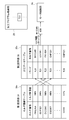
- FIG. 4 is a diagram showing the relationship between the table structure of the database stored in the first storage unit 34 and the second storage unit 35 and the T code of the machining program.
- the first storage unit 34 stores a holder information table 34a in which holder numbers of a plurality of tool holders 11 that can be mounted on each turret surface 10 and torque limit values are associated with each other.
- the second storage unit 35 stores a machining data table 35a in which the T code and the holder number of the tool holder 11 mounted on the turret surface 10 corresponding to each T code are associated and set.
- the data of the first storage unit 34 and the second storage unit 35 may be stored in advance at the time of factory shipment, initial setting, etc., or an operator or the like who operates the automatic lathe 1 can arbitrarily use the operation panel 20. It may be possible to set to.
- the holder information table 34a is stored in advance in the first storage unit 34
- the processing data table 35a of the second storage unit 35 is stored on the operation panel 20 by an operator or the like who operates the automatic lathe 1. It can be set arbitrarily.
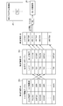
- the screen display unit 31 displays the tool holder selection screen 40 as shown in FIG. 5 on the monitor 22.
- a T code display area 41 for displaying the T code of the turret surface 10 and a holder selection area 42 for selecting the tool holder 11 are provided for each T code (for each turret surface 10). It is provided.
- a holder information display area 43 for displaying detailed information such as a holder number and an image of the tool holder 11 selected in the holder selection area 42 is provided.
- a menu bar 44 or the like for selecting and displaying machining information, holder information, or the like is provided.
- An operator or the like can select a desired tool holder 11 to be mounted on the turret surface 10 in the holder information display area 43 of the tool holder selection screen 40. Therefore, the operator or the like can easily and freely set the holder number in association with the T code.
- the linking unit 32 stores the combination of the T code and the holder number set on the tool holder selection screen 40 in the machining data table 35a of the second storage unit 35.
- the torque limit value setting unit 30 acquires a holder number from the second storage unit 35 based on the T code of the tool selection number described in the machining program so as to select a predetermined tool 12, and uses the acquired holder number as the holder number. Based on this, the torque limit value is acquired from the first storage unit 34.
- the torque limit value setting unit 30 passes the acquired torque limit value to the motor control unit 26 as a torque limit parameter of the machining torque.
- the motor control unit 26 of the control device 3 rotates the turret 8 based on the T code described in the machining program, determines the turret surface 10 corresponding to the T code, and is mounted on the indexed turret surface 10. Select the predetermined tool 12.
- the motor control unit 26 processes the work W with the tool 12 within an appropriate machining torque range that does not exceed the torque limit value based on the torque limit value (torque limit parameter) received from the torque limit value setting device 4. To control.
- each holder number of the plurality of tool holders 11 that can be mounted on the turret surface 10 and the torque limit value of the tool holder 11 corresponding to each holder number are displayed. It is assumed that it is stored in advance.
- a worker or the like attaches a tool 12 necessary for machining to each turret surface 10 of the turret 8 via a predetermined tool holder 11.
- the operator or the like operates the operation panel 20 to instruct the control device 3 to display the tool holder selection screen 40.
- step S1 the screen display unit 31 displays the tool holder selection screen 40 on the monitor 22.
- the operator or the like sets the holder number of the tool holder 11 mounted on the turret surface 10 with respect to the turret surface number of each turret surface 10.
- step S1 is executed after the tool holder 11 is attached to the turret surface 10, but the order is not limited to this.
- an operator or the like may attach the tool holder 11 to the turret surface 10 based on the setting information of the tool holder 11.
- the linking unit 32 When the operator or the like finishes the setting on the tool holder selection screen 40, the linking unit 32 is notified of the combination of the turret surface number and the holder number set corresponding to the turret surface number.
- the linking unit 32 acquires the combination of the turret surface number and the holder number (step S2) and stores it in the processing data table 35a of the second storage unit 35 (step S3).
- the control device 3 receives the machining start instruction and starts executing the machining program of the machining program storage unit 25 (step S4). .. Specifically, the control device 3 sequentially calls and executes the machining command (instruction code) described in the machining program, and performs the machining work of the work W by the machining body 2.
- the control device 3 reads the T code of the turret surface 10 from the machining program by the selection command (command code) of the predetermined tool 12 used for machining (step S5). Then, based on this T code, the motor control unit 26 of the control device 3 drives the turret turning motor 15 to determine the turret surface 10 (step S6). For example, in the example shown in FIG. 4, the control device 3 reads "T21" as a T code from the machining program.
- the motor control unit 26 determines the turret surface 10 corresponding to "T21", and the turret surface 10 is subjected to the tool holder 11 by the offset value of the offset number and the correction value of the coordinate correction value number specified together with the T21.
- the mounted tool 12 is indexed.
- the torque limit value setting unit 30 receives the instruction from the machining data table 35a of the second storage unit 35 according to the instruction from the control device 3. Acquire the holder number corresponding to the T code (step S7).
- the torque limit value setting unit 30 acquires "ESS987" associated with "T21".
- the torque limit value setting unit 30 acquires the torque limit value corresponding to the holder number from the holder information table 34a of the first storage unit 34 based on the holder number acquired in step S7, and the motor control unit 26 (Step S8). More specifically, as shown in FIG. 4, the torque limit value setting unit 30 acquires "400%” as the torque limit value, and sets "400" (torque limit parameter) to the address "# 12345" on the memory. Write.
- the motor control unit 26 reads the torque limit parameter "400" from the address of "# 12345” and receives it as the torque limit value from the torque limit value setting unit 30. By controlling the drive mechanism 17, the motor control unit 26 processes the work W by the tool 12 with an appropriate processing torque that does not exceed the torque limit value (step S9).
- the torque limit value setting device 4 and the automatic lathe 1 according to the second embodiment further include a third storage unit 36 shown by a broken line in FIG. 3, but the torque limit value according to the first embodiment shown in FIG. It has the same basic configuration as the setting device 4 and the automatic lathe 1. Therefore, in the following, a configuration different from the first embodiment will be mainly described, and a detailed description of the same configuration as the first embodiment will be omitted.
- FIG. 7 is a diagram showing the relationship between the table structure of the database stored in the first storage unit 34, the second storage unit 35, and the third storage unit 36 and the T code of the processing program.
- the holder information table 34a in which the holder number and the torque limit value are associated with each other is stored in advance in the first storage unit 34, as in the first embodiment.
- the second storage unit 35 stores the processing data table 35a in which the T code and the holder number are associated with each other.
- the combination of the T code and the holder number stored in the second storage unit 35 is set from the tool holder selection screen 40.
- the torque limit value is stored in association with the T code based on the data stored in the first and second storage units 34 and 35.
- the register of the CPU is the third storage unit 36, but the present invention is not limited to this.
- the torque limit value setting unit 30 acquires a holder number corresponding to each T code from the second storage unit for each T code, and based on the acquired holder number, the first storage unit 34 transfers the holder number to the holder number. Get the corresponding torque limit.
- the torque limit value setting unit 30 stores the acquired torque limit value in the third storage unit 36 in association with the T code. More specifically, as shown in FIG. 7, the torque limit value setting unit 30 sequentially sets the acquired torque limit value in the register which is the third storage unit 36 in the T code order (T20 to T29). ..
- the torque limit value setting unit 30 starts from the third storage unit 36 based on the T code of the tool selection number described in the machining program so as to select the predetermined tool 12. Get the torque limit value. Based on the acquired torque limit value, the motor control unit 26 controls the work W to be machined by the tool 12 within an appropriate machining torque range that does not exceed the torque limit value.
- the holder information table 34a of the first storage unit 34 contains the holder numbers of the plurality of tool holders 11 that can be mounted on the turret surface 10, and the torque limit values of the tool holders 11 corresponding to the holder numbers. Is stored in advance.
- the tool 12 required for machining is mounted on each turret surface 10 of the turret 8 by an operator or the like via a predetermined tool holder 11.
- step S20 When an operator or the like operates the operation panel 20 to instruct the control device 3 to display the tool holder selection screen 40, in step S20, the screen display unit 31 that receives this instruction monitors the tool holder selection screen 40 22. Display on.
- the linking unit 32 acquires the combination of the T code and the holder number set on the tool holder selection screen 40, and stores it in the machining data table 35a of the second storage unit 35 in step S22.
- step S23 the torque limit value setting unit 30 acquires all combinations of the T code and the holder number from the second storage unit 35, and based on the holder number of each combination, from the first storage unit 34, Acquire the torque limit value corresponding to the T code.
- step S24 the torque limit value setting unit 30 stores each acquired torque limit value in the third storage unit 36 in association with the T code (see FIG. 7).
- step S25 the control device 3 starts executing the machining program.
- step S26 the control device 3 reads the T code of the turret surface 10 from the machining program according to the selection command (command code) of the predetermined tool 12 used for machining.
- step S27 the motor control unit 26 drives the turret turning motor 15 based on the T code to determine the turret surface 10, so that the tool 12 is also determined.
- the turret surface 10 corresponding to the T code “T21” is determined, and the tool holder 11 is placed on the turret surface 10 by the offset value of the offset number and the correction value of the coordinate correction value number specified together with T21.
- the tool 12 mounted via the is indexed.
- step S28 the torque limit value setting unit 30 acquires the torque limit value corresponding to the T code from the third storage unit 36 and passes it to the motor control unit 26.
- the torque limit value setting unit 30 acquires the torque limit value “400%” associated with the T code “T21” and passes the torque limit value “#” on the memory to the motor control unit 26. Write “400" in "12345".
- step S29 the motor control unit 26 reads the torque limit parameter "400" from the address of "# 12345” and receives it as the torque limit value from the torque limit value setting unit 30.
- the motor control unit 26 controls the drive mechanism 17, so that the tool 12 processes the work W with an appropriate processing torque that does not exceed the torque limit value.
- the torque limit value setting unit 30 acquires the holder number (tool holder number) associated with the T code from the second storage unit 35.
- the torque limit value setting unit 30 acquires the torque limit value associated with the holder number from the first storage unit based on the acquired holder number.
- the turret surface 10 is determined based on the T code described in the machining program while executing the machining program, so that the turret surface 10 is mounted on the turret surface 10 via the tool holder 11.
- the turret 12 can be easily and freely selected. Further, based on this T code, the torque limit value corresponding to the selected tool 12 can be easily and appropriately acquired and passed to the motor control unit 26 (control unit). Further, even when the tool holder 11 mounted on the turret surface 10 is changed, an appropriate torque limit value corresponding to the changed tool holder 11 can be obtained by updating the second storage unit 35.
- a torque limit value setting device 4 capable of setting a limit value can be provided.
- the automatic lathe 1 which is a machine tool according to the first and second embodiments, determines the turret surface 10 based on the T code (turret surface number) described in the machining program, thereby forming the turret surface 10 on the turret surface 10.
- the tool 12 mounted via the tool holder 11 is selected.
- the motor control unit 26 controls machining by the tool 12 based on the torque limit value set by the torque limit value setting device 4 based on the T code.
- the torque limit value setting device 4 which is a tool information setting device, monitors the tool holder selection screen 40 for selecting the tool holder 11 to be mounted on the turret surface 10 (display unit).
- the holder number (tool holder number) of the screen display unit 31 displayed on the screen and the tool holder 11 selected on the tool holder selection screen 40 is associated with the T code (turret surface number) of the turret surface 10 and is associated with the first storage unit. It is provided with a linking unit 32 stored in 34.
- the linking unit 32 stores the torque limit value corresponding to the tool holder 11 of the selected tool 12 in the first storage unit 34, so that the torque limit value setting unit is set for the tool 12 of the tool holder 11. 30 can set an appropriate torque limit value.
- the torque limit value setting device 4 includes a third storage unit 36 that stores each T code (turret surface number) of the plurality of turret surfaces 10 and the torque limit value in association with each other.
- the torque limit value setting unit 30 acquires a combination of the T code (turret surface number) and the holder number (tool holder number) from the second storage unit 35, and the first is based on the holder number (tool holder number) of each combination. 1 Torque limit values are acquired from the storage unit 34.
- the torque limit value setting unit 30 stores each acquired torque limit value in the third storage unit 36 in association with the T code (turret surface number). Then, the torque limit value setting unit 30 acquires the torque limit value from the third storage unit 36 based on the T code (turret surface number) described in the machining program.
- the torque limit value can be set more quickly and efficiently for the tool 12 mounted on the turret surface 10 via the tool holder 11 based on the T code (turret surface number), and the machining program can be executed.
- the speed can be increased and the processing efficiency can be improved.
- the torque limit value can be set not only in the holder number.
- the distance (position information) of each axis (X-axis, Y-axis, Z-axis) to the work W of the cutting edge of the tool 12 installed on the turret surface 10 via a predetermined tool holder 11 is set as tool information (core, diameter). , Longitudinal) can be set.
- the tool information is the core, the diameter, and the length will be described.
- the tool information setting device 4 and the automatic lathe 1 according to the third embodiment functions as a position information setting device, and the torque limit value setting unit 30 is positioned. It has the same basic configuration as the first embodiment and the second embodiment shown in FIG. 3, except that it functions as an information setting unit. Therefore, in the following, configurations different from those of the first embodiment and the second embodiment will be mainly described, and detailed description of the same configurations as those of the first embodiment and the second embodiment will be omitted.
- the tool information in the third embodiment is the position information of the tool 12, and specifically, it is used for external cutting and inner diameter cutting when, for example, the work W held by the spindle 5 is machined by the tool 12.
- This is three-dimensional position information of the core, diameter, and length for setting the coordinate position of the cutting edge of the tool 12.
- the core is the coordinate position of the X axis in the X direction in which the cutting edge is brought into contact with the work W by moving the tool 12 with a tool post or the like.
- the diameter is the coordinate position of the cutting edge of the tool 12 on the Y axis in the Y direction.
- the length is the coordinate position of the Z axis in the Z direction of the cutting edge with respect to the end face position of the work W.
- FIG. 9 shows the relationship between the table structure of the database stored in the first storage unit 34 and the second storage unit 35 and the T code of the processing program in the third embodiment.
- the holder numbers of a plurality of tool holders 11 that can be mounted on each turret surface 10 and the position information of the cutting edge (machining point) of the tool 12 as tool information ( The holder information table 34a associated with the X-axis coordinate position of the core, the Y-axis coordinate position of the diameter, and the longitudinal Z-axis coordinate position) is stored.
- the second storage unit 35 stores a machining data table 35a in which the T code and the holder number of the tool holder 11 mounted on the turret surface 10 corresponding to each T code are associated and set. These data can be set by the same procedure using the same screens as in the first and second embodiments.
- each holder number of the plurality of tool holders 11 that can be mounted on the turret surface 10 and the position information (tool information) of the tool holder 11 corresponding to each holder number are displayed. Is stored in advance. Further, the operator or the like attaches the tool 12 to each turret surface 10 of the turret 8 via a predetermined tool holder 11, operates the operation panel 20, and displays the tool holder selection screen 40 on the control device 3. It shall be instructed.
- step S1 the screen display unit 31 displays the tool holder selection screen 40 on the monitor 22.
- step S2 the linking unit 32 acquires the combination of the turret surface number and the holder number set by the operator or the like on the tool holder selection screen 40, and in step S3, the machining data table 35a of the second storage unit 35 Remember in.
- step S4 the control device 3 starts executing the machining program of the machining program storage unit 25 in response to the machining start instruction from the worker or the like.
- step S5 the control device 3 reads out the T code of the turret surface 10 based on the selection command of the tool 12, and in step S6, the motor control unit 26 drives the turret turning motor 15 to determine the turret surface 10.
- step S7 the torque limit value setting unit 30 that functions as the position information setting unit acquires the holder number corresponding to the T code from the processing data table 35a of the second storage unit 35.
- the position information setting unit acquires "ESS987" associated with "T21".
- the position information setting unit acquires tool information (position information) corresponding to the holder number from the holder information table 34a of the first storage unit 34 in step S8, and the motor control unit 26 Pass to.
- the position information setting unit acquires the position information "x4, y4, z4" and writes "x4, y4, z4" (tool information parameter) to the address "# 12345" on the memory.
- step S9 the motor control unit 26 controls the drive mechanism 17 based on the tool information parameter “x4, y4, z4” read from the address of “# 12345” to position the cutting edge (machining point) of the tool 12. Do.
- the tool information setting device 4 as the position information setting device has a holder number on each tool holder 11 as in the torque limit value setting in the first embodiment and the second embodiment. And the core, diameter, and length information, which is the tool information of the tool 12 installed in the tool holder 11, is set.
- the replaced turret surface number is changed. Therefore, it becomes easy to change the setting of the tool information (position information of the cutting edge) at the time of tool change.
- the tool post on which the tool 12 and the tool holder 11 are mounted has been described as a turret, but the present disclosure is not limited to this, and the present disclosure is also applied to the tool holder and the tool installed on the comb tool post. It is possible.
Abstract
Description
以下、第1実施形態に係る工具情報設定装置であるトルク制限値設定装置及びトルク制限値設定装置を備えた工作機械について、図面を参照しながら説明する。図1は第1実施形態に係るトルク制限値設定装置を備えた工作機械である自動旋盤のタレット刃物台を示す概略斜視図である。図2はタレットの概略平面図である。図3は、トルク制限値設定装置(工具情報設定装置)を有する制御装置の機能ブロック図である。 (First Embodiment)
Hereinafter, a machine tool provided with a torque limit value setting device and a torque limit value setting device, which are tool information setting devices according to the first embodiment, will be described with reference to the drawings. FIG. 1 is a schematic perspective view showing a turret tool post of an automatic lathe, which is a machine tool provided with a torque limit value setting device according to the first embodiment. FIG. 2 is a schematic plan view of the turret. FIG. 3 is a functional block diagram of a control device having a torque limit value setting device (tool information setting device).
次に、第2実施形態に係る工具情報設定装置であるトルク制限値設定装置及びトルク制限値設定装置を備えた工作機械である自動旋盤について説明する。第2実施形態に係るトルク制限値設定装置4及び自動旋盤1は、図3に破線で示す第3記憶部36をさらに備えたこと以外は、図1に示す第1実施形態に係るトルク制限値設定装置4及び自動旋盤1と同様の基本構成を備えている。このため、以下では第1実施形態と異なる構成について主に説明し、第1実施形態と同様の構成については詳細な説明を省略する。 (Second Embodiment)
Next, an automatic lathe which is a machine tool provided with a torque limit value setting device and a torque limit value setting device which are tool information setting devices according to the second embodiment will be described. The torque limit
第3実施形態に工具情報設定装置を備えた工作機械である自動旋盤について、図3を参照しながら説明する。第3実施形態に係る工具情報設定装置4及び自動旋盤1は、図3に示す工具情報設定装置(トルク制限値設定装置)4が位置情報設定装置として機能し、トルク制限値設定部30が位置情報設定部として機能すること以外は、図3に示す第1実施形態及び第2実施形態と同様の基本構成を備えている。このため、以下では第1実施形態及び第2実施形態と異なる構成について主に説明し、第1実施形態及び第2実施形態と同様の構成については詳細な説明を省略する。 (Third Embodiment)
An automatic lathe, which is a machine tool provided with a tool information setting device in the third embodiment, will be described with reference to FIG. In the tool
Claims (6)
- タレットの周面に複数設けられたタレット面の各々に、加工に応じて工具ホルダを介して装着された工具の工具情報を設定する工具情報設定装置であって、
前記工具ホルダを識別する工具ホルダ番号及び前記工具ホルダに装着する前記工具の工具情報が対応づけられて記憶されている第1記憶部と、
前記タレット面を識別するタレット面番号及び前記タレット面に装着される前記工具ホルダの前記工具ホルダ番号が対応づけられて記憶されている第2記憶部と、
所定の前記工具を、装着されている前記タレット面の前記タレット面番号によって選択する際に、加工プログラムに記載された前記タレット面番号に基づいて前記第2記憶部から前記工具ホルダ番号を取得し、取得した前記工具ホルダ番号に基づいて前記第1記憶部から前記工具の工具情報を取得する工具情報設定部と、
を備えたことを特徴とする工具情報設定装置。 It is a tool information setting device that sets tool information of a tool mounted via a tool holder on each of a plurality of turret surfaces provided on the peripheral surface of the turret according to machining.
A first storage unit that stores the tool holder number that identifies the tool holder and the tool information of the tool that is attached to the tool holder in association with each other.
A second storage unit in which the turret surface number for identifying the turret surface and the tool holder number of the tool holder mounted on the turret surface are stored in association with each other.
When the predetermined tool is selected by the turret surface number of the mounted turret surface, the tool holder number is acquired from the second storage unit based on the turret surface number described in the machining program. , A tool information setting unit that acquires tool information of the tool from the first storage unit based on the acquired tool holder number, and
A tool information setting device characterized by being equipped with. - 複数の前記タレット面の各タレット面番号と前記工具の工具情報とを対応づけて記憶する第3記憶部を備え、
前記工具情報設定部は、前記第2記憶部から前記タレット面番号と前記工具ホルダ番号との組み合わせを取得し、各組み合わせの前記工具ホルダ番号に基づいて前記第1記憶部から前記工具情報をそれぞれ取得し、取得した各工具情報を、前記タレット面番号と対応づけて、前記第3記憶部に記憶しておき、前記加工プログラムに記載された前記タレット面番号に基づいて、前記第3記憶部から前記工具情報を取得することを特徴とする請求項1に記載の工具情報設定装置。 It is provided with a third storage unit that stores each turret surface number of the plurality of turret surfaces in association with the tool information of the tool.
The tool information setting unit acquires a combination of the turret surface number and the tool holder number from the second storage unit, and obtains the tool information from the first storage unit based on the tool holder number of each combination. Each acquired tool information is associated with the turret surface number and stored in the third storage unit, and the third storage unit is stored based on the turret surface number described in the machining program. The tool information setting device according to claim 1, wherein the tool information is acquired from the tool. - 前記タレット面に装着する前記工具ホルダを選択する工具ホルダ選択画面を表示部に表示する画面表示部と、
前記工具ホルダ選択画面で選択された前記工具ホルダの前記工具ホルダ番号を、前記タレット面番号と対応づけて前記第1記憶部に記憶する連係部と、
を備えることを特徴とする請求項1または2に記載の工具情報設定装置。 A screen display unit that displays a tool holder selection screen for selecting the tool holder to be mounted on the turret surface on the display unit, and
A linking unit that stores the tool holder number of the tool holder selected on the tool holder selection screen in the first storage unit in association with the turret surface number.
The tool information setting device according to claim 1 or 2, wherein the tool information setting device is provided. - 前記工具情報が、前記工具の加工トルクのトルク制限値であることを特徴とする請求項1~3の何れか一項に記載の工具情報設定装置。 The tool information setting device according to any one of claims 1 to 3, wherein the tool information is a torque limit value of the machining torque of the tool.
- 前記工具情報が、前記工具の位置情報であることを特徴とする請求項1~3の何れか一項に記載の工具情報設定装置。 The tool information setting device according to any one of claims 1 to 3, wherein the tool information is the position information of the tool.
- タレットの周面に複数設けられたタレット面の各々にタレット面番号が設定され、所定の工具が、工具ホルダを介して装着されている前記タレット面番号の指定により、前記タレット面を割り出すことによって選択され、選択された前記工具によってワークを加工する工作機械であって、
請求項1~5の何れか一項に記載の工具情報設定装置と、
加工プログラムに記載された前記タレット面番号に基づいて、前記タレット面を割り出すことで、当該タレット面に前記工具ホルダを介して装着された前記工具を選択し、前記タレット面番号に基づいて前記工具情報設定装置により設定された工具情報に基づいて、前記工具による加工を制御する制御部と、
を備えることを特徴とする工作機械。 A turret surface number is set for each of a plurality of turret surfaces provided on the peripheral surface of the turret, and the turret surface is determined by designating the turret surface number on which a predetermined tool is mounted via a tool holder. A machine tool that is selected and processes a workpiece with the selected tool.
The tool information setting device according to any one of claims 1 to 5.
By indexing the turret surface based on the turret surface number described in the machining program, the tool mounted on the turret surface via the tool holder is selected, and the tool is selected based on the turret surface number. A control unit that controls machining with the tool based on the tool information set by the information setting device, and
A machine tool characterized by being equipped with.
Priority Applications (5)
| Application Number | Priority Date | Filing Date | Title |
|---|---|---|---|
| US17/629,745 US20220253036A1 (en) | 2019-07-25 | 2020-07-15 | Tool information setting device and machine tool |
| KR1020227005594A KR20220043142A (en) | 2019-07-25 | 2020-07-15 | TOOL INFORMATION SETTING DEVICE AND MACHINE TOOL |
| EP20844165.9A EP4006664A4 (en) | 2019-07-25 | 2020-07-15 | Tool information setting device and machine tool |
| JP2021533972A JP7434326B2 (en) | 2019-07-25 | 2020-07-15 | Tool information setting device and machine tool |
| CN202080051813.7A CN114127649A (en) | 2019-07-25 | 2020-07-15 | Tool information setting device and machine tool |
Applications Claiming Priority (2)
| Application Number | Priority Date | Filing Date | Title |
|---|---|---|---|
| JP2019136800 | 2019-07-25 | ||
| JP2019-136800 | 2019-07-25 |
Publications (1)
| Publication Number | Publication Date |
|---|---|
| WO2021015064A1 true WO2021015064A1 (en) | 2021-01-28 |
Family
ID=74193485
Family Applications (1)
| Application Number | Title | Priority Date | Filing Date |
|---|---|---|---|
| PCT/JP2020/027439 WO2021015064A1 (en) | 2019-07-25 | 2020-07-15 | Tool information setting device and machine tool |
Country Status (7)
| Country | Link |
|---|---|
| US (1) | US20220253036A1 (en) |
| EP (1) | EP4006664A4 (en) |
| JP (1) | JP7434326B2 (en) |
| KR (1) | KR20220043142A (en) |
| CN (1) | CN114127649A (en) |
| TW (1) | TW202113520A (en) |
| WO (1) | WO2021015064A1 (en) |
Citations (8)
| Publication number | Priority date | Publication date | Assignee | Title |
|---|---|---|---|---|
| JPS6254153B2 (en) | 1978-07-17 | 1987-11-13 | Conoco Inc | |
| JPH079301A (en) * | 1993-06-30 | 1995-01-13 | Star Micronics Co Ltd | Producing method of tool unit form |
| JPH09179620A (en) * | 1995-12-26 | 1997-07-11 | Toyota Central Res & Dev Lab Inc | Method and device for deciding format of object to be interfered, automatic decision method for work supporting format and for tooling format |
| JPH1058279A (en) * | 1996-08-22 | 1998-03-03 | Star Micronics Co Ltd | Turret tool selection instruction method |
| WO2014168152A1 (en) * | 2013-04-11 | 2014-10-16 | シチズンホールディングス株式会社 | Offset number setting device |
| US20160187871A1 (en) * | 2012-10-18 | 2016-06-30 | Doosan Infracore Co., Ltd | Method for managing turret tools by using visual information for machine tool |
| WO2018173434A1 (en) * | 2017-03-24 | 2018-09-27 | Dmg森精機株式会社 | Working condition setting method and working condition setting device |
| JP2019136800A (en) | 2018-02-07 | 2019-08-22 | 日鉄日新製鋼株式会社 | Cutting machine and method for manufacturing composite architectural material using the same |
Family Cites Families (8)
| Publication number | Priority date | Publication date | Assignee | Title |
|---|---|---|---|---|
| JP3186837B2 (en) * | 1992-06-22 | 2001-07-11 | 積水化学工業株式会社 | Work instruction display system |
| JPH11296217A (en) * | 1998-04-03 | 1999-10-29 | Hitachi Seiki Co Ltd | Method and device for transferring program file in nc device |
| JP4047986B2 (en) * | 1998-11-04 | 2008-02-13 | 森精機興産株式会社 | Numerical control method and apparatus |
| JP4310018B2 (en) * | 2000-03-14 | 2009-08-05 | 株式会社森精機製作所 | Tool position correction method for NC machine tools |
| JP4738585B2 (en) * | 2000-10-26 | 2011-08-03 | シチズンホールディングス株式会社 | Machining program graph display method and apparatus therefor |
| JP3995558B2 (en) * | 2002-08-20 | 2007-10-24 | シチズンホールディングス株式会社 | Control method and control device for tool selection operation of turret tool post |
| JP6409586B2 (en) * | 2015-01-19 | 2018-10-24 | 村田機械株式会社 | Machine tool system and rule setting method |
| WO2016185948A1 (en) * | 2015-05-20 | 2016-11-24 | シチズン時計株式会社 | Operation panel for machine tool |
-
2020
- 2020-07-15 US US17/629,745 patent/US20220253036A1/en active Pending
- 2020-07-15 CN CN202080051813.7A patent/CN114127649A/en active Pending
- 2020-07-15 WO PCT/JP2020/027439 patent/WO2021015064A1/en active Application Filing
- 2020-07-15 KR KR1020227005594A patent/KR20220043142A/en unknown
- 2020-07-15 EP EP20844165.9A patent/EP4006664A4/en active Pending
- 2020-07-15 JP JP2021533972A patent/JP7434326B2/en active Active
- 2020-07-22 TW TW109124720A patent/TW202113520A/en unknown
Patent Citations (8)
| Publication number | Priority date | Publication date | Assignee | Title |
|---|---|---|---|---|
| JPS6254153B2 (en) | 1978-07-17 | 1987-11-13 | Conoco Inc | |
| JPH079301A (en) * | 1993-06-30 | 1995-01-13 | Star Micronics Co Ltd | Producing method of tool unit form |
| JPH09179620A (en) * | 1995-12-26 | 1997-07-11 | Toyota Central Res & Dev Lab Inc | Method and device for deciding format of object to be interfered, automatic decision method for work supporting format and for tooling format |
| JPH1058279A (en) * | 1996-08-22 | 1998-03-03 | Star Micronics Co Ltd | Turret tool selection instruction method |
| US20160187871A1 (en) * | 2012-10-18 | 2016-06-30 | Doosan Infracore Co., Ltd | Method for managing turret tools by using visual information for machine tool |
| WO2014168152A1 (en) * | 2013-04-11 | 2014-10-16 | シチズンホールディングス株式会社 | Offset number setting device |
| WO2018173434A1 (en) * | 2017-03-24 | 2018-09-27 | Dmg森精機株式会社 | Working condition setting method and working condition setting device |
| JP2019136800A (en) | 2018-02-07 | 2019-08-22 | 日鉄日新製鋼株式会社 | Cutting machine and method for manufacturing composite architectural material using the same |
Non-Patent Citations (1)
| Title |
|---|
| See also references of EP4006664A4 |
Also Published As
| Publication number | Publication date |
|---|---|
| US20220253036A1 (en) | 2022-08-11 |
| JPWO2021015064A1 (en) | 2021-01-28 |
| EP4006664A4 (en) | 2023-08-02 |
| JP7434326B2 (en) | 2024-02-20 |
| EP4006664A1 (en) | 2022-06-01 |
| CN114127649A (en) | 2022-03-01 |
| TW202113520A (en) | 2021-04-01 |
| KR20220043142A (en) | 2022-04-05 |
Similar Documents
| Publication | Publication Date | Title |
|---|---|---|
| US7848851B2 (en) | Controller of work piece-conveying robot | |
| US10025292B2 (en) | Offset number setting device for setting an offset number for a tool attached to a turret surface | |
| JP4256353B2 (en) | Servo control device and servo system adjustment method | |
| EP1145804B1 (en) | Robot controller | |
| JP5220183B2 (en) | Numerical control device and control method of the numerical control device | |
| JP4695727B1 (en) | Numerically controlled machine tool | |
| WO2014068667A1 (en) | Processing program generation method and device | |
| JP2002172543A (en) | Control parameter setting system and control parameter setting method for machining device | |
| JP5452788B1 (en) | Numerical controller | |
| US7292913B2 (en) | Articulated robot | |
| JP6196708B2 (en) | Machining program creation method and apparatus | |
| JP4503326B2 (en) | Tool path data generation device and control device including the same | |
| JP2006085486A (en) | Nc working simulation method and nc working simulation device | |
| JP2762788B2 (en) | Moving body operation display device and display method thereof | |
| WO2021015064A1 (en) | Tool information setting device and machine tool | |
| JP2005319531A (en) | Numerical control machine tool and method for checking machining program | |
| JP2005305579A (en) | Control method and controller for nc machine tool | |
| JP2016049600A (en) | Turret tool rest, machine tool equipped with the turret tool rest, and control method for turret swivel | |
| JPH0739069B2 (en) | Numerical control machine tool | |
| JPH0744215A (en) | Method and device for controlling feeding shaft of machine tool | |
| JP2639756B2 (en) | Method and apparatus for displaying effective series in multi-series NC apparatus | |
| JP2022187129A (en) | Information processing device and information processing program | |
| JP2020049555A (en) | Processing apparatus and processing method | |
| JPH04131909A (en) | Setting method for machining coordinate system of numerically controlled combination lathe | |
| JPH06170695A (en) | Machine tool provided with action direction displaying function |
Legal Events
| Date | Code | Title | Description |
|---|---|---|---|
| 121 | Ep: the epo has been informed by wipo that ep was designated in this application |
Ref document number: 20844165 Country of ref document: EP Kind code of ref document: A1 |
|
| ENP | Entry into the national phase |
Ref document number: 2021533972 Country of ref document: JP Kind code of ref document: A |
|
| NENP | Non-entry into the national phase |
Ref country code: DE |
|
| ENP | Entry into the national phase |
Ref document number: 20227005594 Country of ref document: KR Kind code of ref document: A |
|
| WWE | Wipo information: entry into national phase |
Ref document number: 2020844165 Country of ref document: EP |