WO2021014751A1 - 画像表示装置、方法及びプログラム - Google Patents
画像表示装置、方法及びプログラム Download PDFInfo
- Publication number
- WO2021014751A1 WO2021014751A1 PCT/JP2020/021027 JP2020021027W WO2021014751A1 WO 2021014751 A1 WO2021014751 A1 WO 2021014751A1 JP 2020021027 W JP2020021027 W JP 2020021027W WO 2021014751 A1 WO2021014751 A1 WO 2021014751A1
- Authority
- WO
- WIPO (PCT)
- Prior art keywords
- image
- display
- dimensional model
- unit
- displayed
- Prior art date
- Legal status (The legal status is an assumption and is not a legal conclusion. Google has not performed a legal analysis and makes no representation as to the accuracy of the status listed.)
- Ceased
Links
Images







Classifications
-
- G—PHYSICS
- G06—COMPUTING OR CALCULATING; COUNTING
- G06T—IMAGE DATA PROCESSING OR GENERATION, IN GENERAL
- G06T7/00—Image analysis
- G06T7/0002—Inspection of images, e.g. flaw detection
- G06T7/0004—Industrial image inspection
-
- G—PHYSICS
- G06—COMPUTING OR CALCULATING; COUNTING
- G06F—ELECTRIC DIGITAL DATA PROCESSING
- G06F16/00—Information retrieval; Database structures therefor; File system structures therefor
- G06F16/50—Information retrieval; Database structures therefor; File system structures therefor of still image data
- G06F16/54—Browsing; Visualisation therefor
-
- G—PHYSICS
- G06—COMPUTING OR CALCULATING; COUNTING
- G06F—ELECTRIC DIGITAL DATA PROCESSING
- G06F16/00—Information retrieval; Database structures therefor; File system structures therefor
- G06F16/50—Information retrieval; Database structures therefor; File system structures therefor of still image data
- G06F16/53—Querying
- G06F16/538—Presentation of query results
-
- G—PHYSICS
- G06—COMPUTING OR CALCULATING; COUNTING
- G06F—ELECTRIC DIGITAL DATA PROCESSING
- G06F16/00—Information retrieval; Database structures therefor; File system structures therefor
- G06F16/50—Information retrieval; Database structures therefor; File system structures therefor of still image data
- G06F16/58—Retrieval characterised by using metadata, e.g. metadata not derived from the content or metadata generated manually
-
- G—PHYSICS
- G06—COMPUTING OR CALCULATING; COUNTING
- G06F—ELECTRIC DIGITAL DATA PROCESSING
- G06F16/00—Information retrieval; Database structures therefor; File system structures therefor
- G06F16/50—Information retrieval; Database structures therefor; File system structures therefor of still image data
- G06F16/58—Retrieval characterised by using metadata, e.g. metadata not derived from the content or metadata generated manually
- G06F16/587—Retrieval characterised by using metadata, e.g. metadata not derived from the content or metadata generated manually using geographical or spatial information, e.g. location
-
- G—PHYSICS
- G06—COMPUTING OR CALCULATING; COUNTING
- G06F—ELECTRIC DIGITAL DATA PROCESSING
- G06F3/00—Input arrangements for transferring data to be processed into a form capable of being handled by the computer; Output arrangements for transferring data from processing unit to output unit, e.g. interface arrangements
- G06F3/01—Input arrangements or combined input and output arrangements for interaction between user and computer
- G06F3/048—Interaction techniques based on graphical user interfaces [GUI]
- G06F3/0481—Interaction techniques based on graphical user interfaces [GUI] based on specific properties of the displayed interaction object or a metaphor-based environment, e.g. interaction with desktop elements like windows or icons, or assisted by a cursor's changing behaviour or appearance
-
- G—PHYSICS
- G06—COMPUTING OR CALCULATING; COUNTING
- G06F—ELECTRIC DIGITAL DATA PROCESSING
- G06F3/00—Input arrangements for transferring data to be processed into a form capable of being handled by the computer; Output arrangements for transferring data from processing unit to output unit, e.g. interface arrangements
- G06F3/01—Input arrangements or combined input and output arrangements for interaction between user and computer
- G06F3/048—Interaction techniques based on graphical user interfaces [GUI]
- G06F3/0481—Interaction techniques based on graphical user interfaces [GUI] based on specific properties of the displayed interaction object or a metaphor-based environment, e.g. interaction with desktop elements like windows or icons, or assisted by a cursor's changing behaviour or appearance
- G06F3/04815—Interaction with a metaphor-based environment or interaction object displayed as three-dimensional [3D], e.g. changing the user viewpoint with respect to the environment or object
-
- G—PHYSICS
- G06—COMPUTING OR CALCULATING; COUNTING
- G06T—IMAGE DATA PROCESSING OR GENERATION, IN GENERAL
- G06T15/00—Three-dimensional [3D] image rendering
- G06T15/04—Texture mapping
-
- G—PHYSICS
- G06—COMPUTING OR CALCULATING; COUNTING
- G06T—IMAGE DATA PROCESSING OR GENERATION, IN GENERAL
- G06T19/00—Manipulating three-dimensional [3D] models or images for computer graphics
-
- G—PHYSICS
- G06—COMPUTING OR CALCULATING; COUNTING
- G06T—IMAGE DATA PROCESSING OR GENERATION, IN GENERAL
- G06T19/00—Manipulating three-dimensional [3D] models or images for computer graphics
- G06T19/20—Editing of three-dimensional [3D] images, e.g. changing shapes or colours, aligning objects or positioning parts
-
- G—PHYSICS
- G06—COMPUTING OR CALCULATING; COUNTING
- G06T—IMAGE DATA PROCESSING OR GENERATION, IN GENERAL
- G06T2200/00—Indexing scheme for image data processing or generation, in general
- G06T2200/24—Indexing scheme for image data processing or generation, in general involving graphical user interfaces [GUIs]
-
- G—PHYSICS
- G06—COMPUTING OR CALCULATING; COUNTING
- G06T—IMAGE DATA PROCESSING OR GENERATION, IN GENERAL
- G06T2207/00—Indexing scheme for image analysis or image enhancement
- G06T2207/10—Image acquisition modality
- G06T2207/10028—Range image; Depth image; 3D point clouds
Definitions
- the present invention relates to an image display device, a method, and a program, and particularly relates to a technique for making it easier to grasp the relationship between a subject and a captured image obtained by capturing a part of the subject.
- Patent Document 1 An image management device has been proposed that can collectively acquire an image for each structural group of a structure from a large number of images of the structure.
- the image management device described in Patent Document 1 displays a three-dimensional point cloud related to a structure or a three-dimensional model composed of a mesh generated based on the three-dimensional point cloud on a display unit, and the displayed three-dimensional point cloud.
- a segment that is a structural unit in the structure from the 3D point cloud based on the specified 3D coordinates. Extract the 3D points corresponding to.
- the segment corresponds to the inspection target part of the structure, and is, for example, a main girder, a floor slab, or the like in an inspection targeting a bridge.
- This image management device acquires an image associated with a three-dimensional point corresponding to the extracted segment from an image storage unit that stores an image of a structure, and displays the acquired image on the display unit.
- a segment (when the structure is a bridge, a main girder or a main girder) which is a structural unit in the structure is based on the three-dimensional coordinates of the structure specified by the user. It is possible to identify the inspection target part such as the floor slab), acquire the image associated with the segment, and present it to the user.
- the shooting range of the captured image is smaller than that of the structure, there are many similar captured images. Therefore, the user compares the captured image with the structure, and the captured image shows any part of the structure. It is not possible to know if it was taken.
- the present invention has been made in view of such circumstances, and when a user selects an arbitrary photographed image from a group of photographed images of a subject such as a structure, the selected photographed image is any part of the subject. It is an object of the present invention to provide an image display device, a method, and a program capable of easily grasping whether or not an image is taken.
- the image display device stores a three-dimensional model of the subject and a group of captured images obtained by changing the shooting position and shooting direction with respect to the subject.
- the first display control unit that displays an image list showing the captured image group on the display unit, the first operation unit that receives an arbitrary captured image selection instruction from the image list, and the selected captured image.
- a position information acquisition unit that acquires position information on the 3D model, and a second display control unit that reads out the 3D model stored in the storage unit and displays it on the display unit, and is acquired by the position information acquisition unit.
- a second display control unit is provided, which superimposes and displays an index indicating the position of the captured image on the three-dimensional model displayed on the display unit based on the position information on the three-dimensional model.
- an image list showing a group of captured images is displayed on the display unit and a user operation receives an instruction to select an arbitrary captured image from the image list
- a three-dimensional model of the subject is displayed on the display unit.
- An index indicating the position of the captured image selected and instructed to be displayed and displayed is superimposed and displayed on the displayed three-dimensional model.
- the user can easily grasp which part of the subject (three-dimensional model) the selected captured image is captured.
- a condition setting unit for setting conditions indicating narrowing down and / or rearranging of the captured images extracted from the captured image group, and a condition set by the condition setting unit.
- An image list showing captured images narrowed down from the captured image group based on the above, and / or an image list creating unit for creating an image list in which the captured images are rearranged are provided, and the first display control unit is displayed on the display unit. It is preferable to update the created image list with the image list created by the image list creation unit. By using the image list generated in this way, the user can easily select a desired captured image from the captured image group.
- the items displayed in the image list are a reduced image of each captured image of the captured image group, identification information for identifying each captured image, and the facing of the captured image with respect to the subject. It is preferable to include one or more of the degree, the distance of the captured image to the subject, the sharpness of the captured image, the inspection record of the subject, the damage detection result or the information indicating whether or not it is linked to the repair record, and the shooting date and time. ..
- the second display control unit displays the three-dimensional model on which the index is superimposed and displayed in the first display area of the display unit, and stores the captured image instructed to be selected. It is preferable to read from the unit and display it in the second display area of the display unit.
- the second display control unit enlarges, translates, or rotates the three-dimensional model to be displayed on the display unit based on the acquired position information on the three-dimensional model. It is preferable to make the index superimposed on the three-dimensional model easy to see.
- the image display device includes a second operation unit that accepts a view operation of a three-dimensional model to be displayed on the display unit, and the second display control unit is a view operation received by the second operation unit. It is preferable to display the three-dimensional model on the display unit based on the above.
- the view operation is an operation of enlarging, reducing, translating, or rotating the three-dimensional model to be displayed on the display unit
- the second display control unit is the second display control unit. 2 It is preferable to enlarge, reduce, translate, or rotate the three-dimensional model to be displayed on the display based on the view operation received by the operation unit.
- the three-dimensional model is represented by a three-dimensional point group consisting of three-dimensional information of a large number of points on the surface of the subject, and many are based on the three-dimensional point group.
- the invention is a step of preparing a storage unit for storing a three-dimensional model of the subject and a group of captured images obtained by changing the shooting position and shooting direction with respect to the subject, and the first display.
- a first display step in which the control unit displays an image list showing a group of captured images on the display unit, a step in which the first operation unit receives an instruction to select an arbitrary captured image from the image list, and a position information acquisition unit select.
- the step of acquiring the position information on the 3D model corresponding to the instructed captured image and the second display step in which the second display control unit reads out the 3D model stored in the storage unit and displays it on the display unit.
- the second display step of superimposing and displaying the index indicating the position of the captured image on the 3D model displayed on the display unit.
- a step of setting conditions indicating narrowing down and / or rearrangement of captured images extracted from a captured image group by a condition setting unit and an image list creation unit An image list showing the captured images narrowed down from the captured image group based on the set conditions, and / or a step of creating an image list in which the captured images are rearranged, and the first display step is performed on the display unit. It is preferable to update the displayed image list with the created image list.
- the items displayed in the image list are a reduced image of each captured image of the captured image group, identification information for identifying each captured image, and the face-to-face of the captured image with respect to the subject. It is preferable to include one or more of the degree, the distance of the captured image to the subject, the sharpness of the captured image, the inspection record of the subject, the damage detection result or the information indicating whether or not it is linked to the repair record, and the shooting date and time. ..
- the three-dimensional model on which the index is superimposed is displayed in the first display area of the display unit, and the captured image instructed to be selected is stored in the storage unit. It is preferable to read from and display it in the second display area of the display unit.
- the second display step enlarges, translates, or rotates the three-dimensional model to be displayed on the display unit based on the acquired position information on the three-dimensional model. It is preferable to make the index superimposed on the three-dimensional model easy to see.
- the second operation unit includes a step of accepting a view operation of the three-dimensional model to be displayed on the display unit, and the second display step is based on the received view operation. It is preferable to display the dimensional model.
- the view operation is an operation of enlarging, reducing, translating, or rotating the three-dimensional model to be displayed on the display unit
- the second display step is the view operation.
- the three-dimensional model to be displayed on the display unit is enlarged, reduced, translated, or rotated based on the above.
- the three-dimensional model is represented by a three-dimensional point group consisting of three-dimensional information of a large number of points on the surface of the subject, and many are based on the three-dimensional point group.
- the invention according to still another aspect is installed in a computer that can access a storage unit that stores a three-dimensional model of the subject and a group of captured images obtained by changing the shooting position and shooting direction with respect to the subject.
- An image display program that has a function to display an image list showing a group of captured images on the display unit, a function to accept an instruction to select an arbitrary captured image from the image list, and a three-dimensional model corresponding to the captured image instructed to be selected.
- a function to acquire the above position information and a function to read out the 3D model stored in the storage unit and display it on the display unit, and display it on the display unit based on the acquired position information on the 3D model.
- This is an image display program that allows a computer to realize a function of superimposing and displaying an index indicating the position of a captured image instructed to be selected on a three-dimensional model.
- a three-dimensional model of the subject is displayed on a display unit and is displayed on the displayed three-dimensional model. Since the index indicating the position of the captured image instructed to be selected is superimposed and displayed, it is possible to easily grasp which part of the subject the captured image selected from the captured image group is captured. it can.
- FIG. 1 is a block diagram showing an example of the hardware configuration of the image display device according to the present invention.
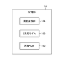
- FIG. 2 is a conceptual diagram showing a group of captured images stored in the storage unit, a three-dimensional model, and an image list.
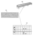
- FIG. 3 is a conceptual diagram showing that a three-dimensional model and an image list are generated based on a group of captured images.
- FIG. 4 is a functional block diagram showing each function of the CPU.
- FIG. 5 is a diagram showing an example of a screen of a display unit on which a three-dimensional model showing a panoramic view of a bridge as a subject is displayed.
- FIG. 1 is a block diagram showing an example of the hardware configuration of the image display device according to the present invention.
- FIG. 2 is a conceptual diagram showing a group of captured images stored in the storage unit, a three-dimensional model, and an image list.
- FIG. 3 is a conceptual diagram showing that a three-dimensional model and an image list are generated based on a group of captured images
- FIG. 6 is a diagram showing an example of a screen of a display unit displaying a three-dimensional model of a bridge that has been three-dimensionally moved by a view operation such as enlargement.
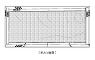
- FIG. 7 is a diagram showing an example of an ortho image corresponding to the coffer of the floor slab, which is one of the management divisions of the bridge.
- FIG. 8 is a diagram showing an example of a damage diagram corresponding to a coffer.
- FIG. 9 is a diagram showing an example of an ortho image on which a damage diagram corresponding to a coffer is superimposed.
- FIG. 10 is a chart showing an example of the damage quantity table corresponding to the coffer.
- FIG. 11 is a chart showing an example of an image list.
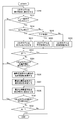
- FIG. 12 is a flowchart showing a second embodiment of the image display method according to the present invention.
- FIG. 13 is a diagram showing a subroutine showing a first example of the process of step S100 shown in FIG.
- FIG. 14 is a diagram showing a subroutine showing a second example of the process of step S100 shown in FIG.
- FIG. 15 is a diagram showing a subroutine showing a third example of the process of step S100 shown in FIG.
- FIG. 16 is a diagram showing an example of a screen of a display unit on which a photographed image instructed to be selected and a three-dimensional model including a photographed range of the photographed image are displayed.
- FIG. 17 is a flowchart showing a first embodiment of the image display method according to the present invention.
- FIG. 17 is a flowchart showing a first embodiment of the image display method according to the present invention.
- FIG. 18 is a diagram showing an example of a screen of a display unit on which an optimum captured image determined from a plurality of captured images is displayed.
- FIG. 19 is a diagram showing another example of the screen of the display unit on which the optimum captured image determined from the plurality of captured images is displayed.
- FIG. 20 is a diagram showing still another example of the screen of the display unit on which the optimum captured image or the like determined from the plurality of captured images is displayed.
- FIG. 1 is a block diagram showing an example of the hardware configuration of the image display device according to the present invention.
- the image display device 10 shown in FIG. 1 a personal computer or a workstation can be used.
- the image display device 10 of this example mainly includes an image acquisition unit 12, a storage unit 16, an operation unit 18, a CPU (Central Processing Unit) 20, a RAM (Random Access Memory) 22, and a ROM (Read Only Memory). It is composed of 24 and a display control unit 26.
- CPU Central Processing Unit
- RAM Random Access Memory
- ROM Read Only Memory
- the image acquisition unit 12 corresponds to an input / output interface and acquires a captured image or the like of a subject.
- the subject of this example is a structure to be inspected, such as a bridge or a tunnel.
- the image acquired by the image acquisition unit 12 is, for example, a large number of images (captured image group) obtained by photographing a subject (structure) with a drone (unmanned aerial vehicle) equipped with a camera. It is preferable that the captured image group covers the entire structure, and the adjacent captured images have overlapping images within a range of about 80%. Therefore, although it depends on the size of the structure, the number of captured images is 1000 or more.
- the captured image group acquired by the image acquisition unit 12 is stored in the storage unit 16.
- the storage unit 16 is a storage unit composed of a hard disk device, a flash memory, and the like. As shown in FIG. 2, the storage unit 16 stores a captured image group 16A, a three-dimensional model 16B of a structure, and an image list 16C. Will be done.
- the three-dimensional model 16B and the image list 16C can be generated based on the captured image group 16A as shown in the conceptual diagram of FIG. The details of the three-dimensional model 16B and the image list 16C will be described later.
- the storage unit 16 stores the operating system, the image display program according to the present invention, various parameters, and the like.
- the operation unit 18 includes a keyboard, a mouse, and the like that are connected to the computer by wire or wirelessly.
- the operation unit 18 functions as an operation unit that accepts normal operation input of the computer, and also takes an arbitrary image from an image list by user operation. It functions as a first operation unit that accepts image selection instructions, and also functions as a second operation unit that accepts view operations including enlargement of a three-dimensional model to be displayed on the screen of the display unit 30, and further responds to user operations. It functions as a third operation unit that receives position information indicating a position on the three-dimensional model displayed on the display unit 30.
- the operation unit 18 serves as an operation unit of a condition setting unit for setting a condition for narrowing down the captured images extracted from the captured image group (narrowing condition) and / or a condition indicating sorting of the captured image group (sorting condition). Function.
- the CPU 20 reads various programs stored in the storage unit 16 or the ROM 24 or the like, and controls each unit in an integrated manner based on the input from the operation unit 18. Further, by executing the image display program according to the present invention, the CPU 20 executes the captured image search unit 20A, the captured image determination unit 20B, the display switching unit 20C, the image list creation unit 20D, and the position information acquisition as shown in FIG. It has functions such as a unit 20E and a condition setting unit 20F.
- the RAM 22 is used as a work area of the CPU 20, and is used as a storage unit for temporarily storing the read program and various data.
- the display control unit 26 functions as a first display control unit for displaying the image list created by the image list creation unit 20D (CPU 20) on the display unit 30, and further reads out the three-dimensional model stored in the storage unit 16.
- the display control unit 26 functions as a third display control unit that reads the captured image determined by the captured image determination unit 20B (CPU 20) from the storage unit 16 and displays the read captured image on the display unit 30. , A part that creates display data to be displayed on the display unit 30 and outputs it to the display unit 30.
- the three-dimensional model stored in the storage unit 16 is read out and the display unit 30 displays the three-dimensional model.
- It functions as a fourth display control unit that enlarges and displays the three-dimensional model based on a view operation including enlargement of the three-dimensional model by the operation unit 18.
- the display unit 30 uses various monitors such as a liquid crystal monitor that can be connected to a computer, and displays various information such as a three-dimensional model, a photographed image, and an image list based on display data input from the display control unit 26. It is also used as part of the user interface together with the operation unit 18.
- monitors such as a liquid crystal monitor that can be connected to a computer, and displays various information such as a three-dimensional model, a photographed image, and an image list based on display data input from the display control unit 26. It is also used as part of the user interface together with the operation unit 18.
- the image display device 10 having the above configuration is operated by the CPU 20 reading the image display program according to the present invention stored in the storage unit 16 or the ROM 24 by inputting an instruction from the operation unit 18 and executing the image display program. Various information is displayed on the display unit 30 according to the operation by the unit 18.
- the three-dimensional model extracts the feature points between the captured images that overlap each other in the captured image group in which the structure is photographed, and estimates the position and orientation of the camera mounted on the drone based on the extracted feature points. It also includes a 3D point cloud in which the 3D position of the feature point is estimated at the same time from the estimation result of the position and orientation of the camera.
- Structure from Motion which tracks the movement of many feature points from a group of captured images in which the shooting position of the camera is moved by the drone, and simultaneously estimates the three-dimensional structure (Structure) and camera posture (Motion) of the structure.
- SfM three-dimensional structure
- bundle adjustment has been developed, and it has become possible to output with high accuracy.
- the absolute scale cannot be obtained by the SfM method, for example, the absolute scale (three-dimensional position) can be obtained by instructing a known size (distance between two points, etc.) of the structure. Can be sought.
- the three-dimensional model is represented by a three-dimensional point cloud of a large number of points on the surface of the structure, and is a structure consisting of a collection of polygonal polygons (for example, a triangular patch) based on the three-dimensional point cloud. It is conceivable that the surface of the object is represented, or a photographed image (texture) obtained by photographing a structure on a polygonal polygon is texture-mapped. In the three-dimensional model of the structure of this example, it is assumed that the captured image is texture-mapped to the polygon of the polygon.
- FIG. 5 is a diagram showing an example of the screen 30A of the display unit 30 on which the three-dimensional model 16B showing the entire view of the bridge 1 is displayed
- FIG. 6 is a diagram showing the bridge 1 three-dimensionally moved by a view operation such as enlargement. It is a figure which shows an example of the screen 30A of the display part 30 which displayed the 3D model 16B of.
- the bridge 1 displayed on the screen 30A includes a main girder 2 passed between the piers 7 and a cross girder 3 provided in a direction orthogonal to the main girder 2 and connecting the main girders. It is composed of various members including an anti-tilt structure 4 and a horizontal structure 5 that connect the main girders 2 to each other in order to resist lateral loads such as wind and earthquake, and a vehicle or the like runs on the upper part of the main girders or the like.
- a floor slab 6 for this purpose has been placed.
- the floor slab 6 is generally made of reinforced concrete.
- the floor slab 6 is usually based on a rectangular coffer defined by the main girder 2 and the cross girder 3, and when inspecting damage to the floor slab (cracks, concrete peeling, etc.), the coffer It is done in units of intervals.
- each coffer of the floor slab is one of the management divisions of the inspection unit of the parts and members that make up the structure (bridge).
- the parts / members that make up the structure that can be the management division of the bridge are the parts / members that make up the structure (main girder 2, horizontal girder 3, anti-tilt structure 4). , Horizontal structure 5, bridge pier 7 (column / wall, beam, corner / joint), etc.
- the storage unit 16 can store management information for each management category of the structure.
- an ortho image corresponding to the management category of the structure an ortho image on which damage information is superimposed, a damage diagram, a damage quantity table, a repair diagram, a repair quantity table, etc. can be considered. ..
- These management information is created when the structure is inspected or repaired.
- FIG. 7 is a diagram showing an example of an ortho image corresponding to the coffer of a bridge.
- the ortho image is an image obtained by projecting a photographed image of the subject (coffer) onto the surface of the coffer.
- the ortho image of one case is an image obtained by extracting a plurality of captured images corresponding to the captured image from the captured image group stored in the storage unit 16, panoramic combining the extracted plurality of captured images, and panoramic combining the images.
- it can be created by projecting and transforming the panoramic composite image so that the image is projected normally on the surface of the space.
- Panorama composition of a plurality of captured images can be performed by image processing in which a plurality of feature points in an overlapping region between captured images that overlap each other are extracted and the extracted plurality of feature points are matched with each other.
- the normal projection of the panoramic composite image onto the coffer plane is performed by a projective transformation that matches the positions corresponding to the four corners of the coffer in the panoramic composite image with the three-dimensional positions of the four corners of the coffer. It can be carried out.
- FIG. 8 is a diagram showing an example of a damage diagram corresponding to the coffer.
- the damage diagram shown in FIG. 8 five cracks C1 to C5 and concrete peeling H1 are shown.
- the damage diagram should be generated by manually tracing the damage such as cracks and peeling visually recognized on the ortho image, or performing image processing to automatically detect the damage from the ortho image and manually correcting it if necessary. Can be done.
- FIG. 9 is a diagram showing an example of an ortho image on which a damage diagram corresponding to a coffer is superimposed.
- the ortho image on which the damage diagram shown in FIG. 9 is superimposed can be created by superimposing the damage diagram shown in FIG. 8 on the ortho image shown in FIG. 7.
- the damage diagram is created with the damaged part colored in a conspicuous color such as red, and the damaged part can be easily visually recognized by superimposing the damage diagram on the ortho image.
- FIG. 10 is a chart showing an example of the damage quantity table corresponding to the coffer.
- the damage quantity table shown in FIG. 10 has items of damage ID (identification), damage type, size (width), size (length), and size (area), and information corresponding to each item is described for each damage. Has been done.
- FIG. 11 is a chart showing an example of the image list 16C.
- the image list 16C shown in FIG. 11 includes attributes of each photographed image of the photographed image group 16A, information for managing each photographed image, information for associating each photographed image with the three-dimensional model 16B, and the like.
- the items displayed in the image list 16C shown in FIG. 11 are a reduced image (thumbnail) of each captured image, identification information (image file name) for identifying each captured image, the degree of confrontation of the captured image with respect to the structure, and the structure. Is it linked to the distance of the photographed image to the image, information indicating whether it is linked to the inspection record of the structure, damage detection results such as cracks (for example, the damage diagram shown in FIG. 8, the damage quantity table shown in FIG. 9)? Includes information indicating whether or not, position information (three-dimensional position information) of the structure shown in each shot image, and shooting date and time.
- the image list 16C is not limited to the above example, and can include the sharpness of each captured image, information indicating whether or not it is associated with the repair record (repair drawing), and the like.
- the degree of face-to-faceness of the captured image means, in this example, the angle formed by the normal direction of the surface of the structure corresponding to the captured image and the shooting direction of the camera at the time of capturing the captured image. Therefore, the smaller the degree of face-to-face (angle), the more the photographed image is photographed facing the structure, and the better the image is.
- the distance of the captured image to the structure is the distance between the structure corresponding to the captured image and the camera at the time of capturing the captured image (shooting distance).
- the position information of the structure shown in the captured image includes the three-dimensional point cloud of the structure within the range shown in the captured image and the representative three-dimensional points of the three-dimensional point cloud (for example, the captured image). It can be a three-dimensional point at or near the four corners).
- the position information of the structure shown in the photographed image is information for associating the photographed image group 16A with the three-dimensional model 16B.
- FIG. 12 is a flowchart showing a second embodiment of the image display method according to the present invention.
- FIG. 12 the second embodiment of the image display method according to the present invention will be described while explaining the operation of each part of the image display device 10 shown in FIGS. 1 and 4.
- the selected captured image corresponds to any position on the three-dimensional model 16B of the structure. This is an easy way to check if it is.
- the display control unit 26 that functions as the first display control unit reads the image list 16C from the storage unit 16 and displays the read image list 16C on the display unit 30 (step S100, first display step).
- the image list 16C contains attributes of each photographed image of the photographed image group 16A, information for managing each photographed image, information for associating each photographed image with the three-dimensional model 16B, and the like. Includes.
- the image list 16C can be created by the CPU 20 that functions as the image list creation unit 20D based on various information associated with the captured image group 16A and the captured image group 16A, but is created by an external device. It may be stored in the storage unit 16.
- step S100 Next, the details of the process in step S100 will be described.
- FIG. 13 is a diagram showing a subroutine showing a first example of the process of step S100.
- the CPU 20 functioning as the condition setting unit 20F sets a condition (narrowing condition) indicating the narrowing down of the captured images extracted from the captured image group 16A by the user operation of the operation unit 18 (step S101).
- the narrowing conditions include information indicating whether or not the photographed image is associated with the inspection record of the structure, information indicating whether or not the photographed image is associated with the damage (crack) detection result, and the repair record (repair drawing). There is information indicating whether or not.
- the narrowing conditions are not limited to the above examples, and for example, information indicating the management classification of the structure can be considered.
- periodic inspections of structures are carried out for each management division, which is the division of inspection units for parts and members that make up the structure.
- the structure is a bridge
- the coffers that make up the plate), bridge piers, etc. correspond to the management categories.
- Information indicating these management categories can be used as a narrowing condition.
- the CPU 20 functioning as the image list creation unit 20D narrows down the captured images to the captured image group 16A based on the filtering conditions set by the condition setting unit 20F, and creates an image list showing the narrowed down captured images ( Step S102).
- the display control unit 26 which functions as the first display control unit, causes the display unit 30 to display an image list of captured images narrowed down according to the narrowing conditions (step S103, first display step). As a result, the image list displayed on the display unit 30 is updated according to the narrowing conditions set by the user.
- the display unit 30 can display an image list consisting of only the photographed images linked to the inspection record.
- the display unit 30 can display an image list consisting of only the photographed images linked to the inspection record.
- the management category of the structure is set as the narrowing condition
- only the captured image associated with the set management category is composed.
- the image list can be displayed on the display unit 30.
- FIG. 14 is a diagram showing a subroutine showing a second example of the process of step S100.
- the CPU 20 functioning as the condition setting unit 20F sets a condition (sort condition) indicating the rearrangement of the captured image group 16A by a user operation in the operation unit 18 (step S104).
- the sorting conditions include the degree of facing of the captured image with respect to the subject (structure), the distance of the captured image with respect to the structure, and the shooting date and time (see FIG. 11).
- the sort condition is not limited to the above example, and may be another sort condition such as the sharpness of each captured image, but the image list 16C may have at least information corresponding to the sort condition. preferable.
- the CPU 20 functioning as the image list creation unit 20D creates an image list in which the captured image group 16A is rearranged based on the sort conditions set by the condition setting unit 20F (step S105).
- the display control unit 26 which functions as the first display control unit, causes the display unit 30 to display the image list of the captured image group 16A sorted according to the sort conditions (step S106, first display step).
- the image list 16C (original image list) stored in the storage unit 16 is displayed on the display unit 30, and a desired item (sort condition) on the displayed image list is clicked according to the sort condition.
- the image list of the captured image group 16A sorted in ascending or descending order can be displayed on the display unit 30.
- FIG. 15 is a diagram showing a subroutine showing a third example of the process of step S100.
- the same step numbers are assigned to the parts common to the processes of the first example and the second example shown in FIGS. 13 and 14, and detailed description thereof will be omitted.
- the third example shown in FIG. 15 is a combination of the first example and the second example shown in FIGS. 13 and 14.
- the captured images are narrowed down to the captured image group 16A based on the narrowing conditions. (Step S101, step S102).
- an image list in which the narrowed down captured images are sorted based on the sorting conditions is created (steps S104 and S105), and the created image list (an image list of the narrowed down and sorted captured images) is created. It is displayed on the display unit 30 (step S107).
- the CPU 20 determines whether or not to end the display of the image list displayed on the display unit 30 (step S108).
- the CPU 20 determines whether or not there is an instruction input for ending the image display from the operation unit 18, and if there is no instruction input for ending (in the case of "No"), the process proceeds to step S110 and there is an instruction input for ending. In the case (in the case of "Yes"), the process related to the image display is terminated.
- step S110 the CPU 20 determines whether or not an arbitrary photographed image selection instruction has been received from the image list in response to a user operation on the operation unit 18 that functions as the first operation unit.
- step S100 the image list is continuously displayed on the display unit 30, and the selection instruction of the captured image can be accepted.
- the CPU 20 functioning as the position information acquisition unit 20E acquires the position information on the three-dimensional model 16B corresponding to the photographed image for which the selection instruction has been instructed. (Step S120).
- the acquisition of the position information can be read from the image list 16C based on the image file name of the captured image instructed to be selected.
- the display control unit 26 that functions as the second display control unit switches the display on the display unit 30 from the display of the image list 16C to the display of the three-dimensional model 16B or the like. That is, the display control unit 26 reads out the three-dimensional model 16B stored in the storage unit 16 and displays it on the display unit 30, and based on the position information on the three-dimensional model 16B acquired by the position information acquisition unit, An index indicating the position of the captured image instructed to be selected is superimposed and displayed on the three-dimensional model 16B displayed on the display unit 30 (step S130, second display step).
- FIG. 16 is a diagram showing an example of the screen 30A of the display unit 30 on which the selected photographed image 100 and the three-dimensional model 16B including the photographing range of the photographed image 100 are displayed.
- the 3D model 16B is automatically enlarged, translated and rotated to display a part of the 3D model 16B so that the position of the captured image 100 on the 3D model 16B can be easily confirmed.
- the view operation such as enlargement of the three-dimensional model 16B is based on the position information of the structure shown in the captured image 100 recorded in the image list 16C (for example, the three-dimensional positions of the four corners of the captured image 100). It can be done automatically.
- the captured image 100 and the three-dimensional model 16B are displayed side by side on the screen 30A of the display unit 30, and the index 100A indicating the position of the captured image 100 is superimposed and displayed on the three-dimensional model 16B.
- This index 100A is displayed as a frame indicating the shooting range of the shot image 100.
- the frame showing the shooting range of the shot image 100 can be composed of line segments connecting the three-dimensional positions of the four corners of the shot image 100.
- a wide range of 3D model 16B can be used. You can manually view (zoom out) the 3D model 16B so that it is displayed, or you can manually view the 3D model 16B so that the entire view of the 3D model 16B (see FIG. 5) is displayed. it can.
- the entire view of the 3D model 16B in which the index indicating the position of the captured image 100 is superimposed and displayed on the 3D model 16B is displayed on the display unit 30 (see FIG. 5).
- the user can roughly grasp which part of the structure the captured image 100 is captured.
- a view operation for manually enlarging the 3D model 16B is performed.
- By performing the rotating view operation it is possible to display the enlarged three-dimensional model 16B on the display unit 30 on which the index indicating the position of the captured image 100 is superimposed and displayed (FIG. FIG. 6. See FIG. 16).
- the user photographs the position of the structure (three-dimensional model 16B) with the captured image selected and instructed on the image list by the index indicating the position of the captured image superimposed and displayed on the three-dimensional model 16B as described above. It is possible to easily grasp what has been done.
- the CPU 20 functioning as the display switching unit 20C determines whether or not to switch the display of the display unit 30 from the display of the three-dimensional model 16B or the like to the display of the image list 16C (step S140).
- the determination of switching to the image list 16C can be performed based on the user operation on the operation unit 18. For example, when the user wants to select a different captured image, the operation unit 18 can perform a switching operation for switching to the display of the image list 16C.
- step S140 when switching from the three-dimensional model 16B or the like to the display of the image list 16C (in the case of "Yes"), the CPU 20 transitions to step S100.
- the image list 16C can be displayed on the display unit 30.
- the CPU 20, which functions as the display switching unit 20C, can switch the function of the display control unit 26 from the second display control unit to the first display control unit when displaying the image list 16C on the display unit 30.
- step S140 determines whether the display is not switched to the image list 16C (in the case of "No"). If it is determined in step S140 that the display is not switched to the image list 16C (in the case of "No"), the CPU 20 transitions to step S150.
- step S150 the CPU 20 determines whether or not there is an instruction input for ending the image display from the operation unit 18, and if there is no instruction input for ending (in the case of "No"), the process returns to step S130 and continues in three dimensions.
- the model 16B and the like are displayed on the display unit 30.
- the process related to the image display is terminated.
- the display of the image list 16C and the display of the three-dimensional model 16B and the like on the display unit 30 are switched based on the user operation and the like, but the display of the image list 16C and the display of the three-dimensional model 16B and the like are displayed. It may be displayed on the unit 30 at the same time.
- FIG. 17 is a flowchart showing a first embodiment of the image display method according to the present invention.
- FIG. 17 the first embodiment of the image display method according to the present invention will be described while explaining the operation of each part of the image display device 10 shown in FIGS. 1 and 4.
- the storage unit 16 of the image display device 10 stores a photographed image group 16A in which a structure (a bridge in this example) is photographed, a three-dimensional model 16B, and an image list 16C.
- the storage unit 16 is prepared in advance.
- the display control unit 26 that functions as the fourth display control unit first reads out the three-dimensional model 16B stored in the storage unit 16 and displays the three-dimensional model 16B on the display unit 30 (step S210).
- the display control unit 26 first displays the three-dimensional model 16B on the display unit 30
- the display control unit 26 provides a panoramic view of the bridge so that the entire bridge 1 which is a structure can be grasped as shown in FIG. It is preferable to display the three-dimensional model 16B shown on the screen 30A of the display unit 30.
- the CPU 20 or the display control unit 26 determines whether or not a view operation such as enlargement has been performed on the three-dimensional model 16B displayed on the screen 30A by the user (step S212).
- the view operation is an operation for enlarging, reducing, translating, or rotating the three-dimensional model 16B expressed in 3D (three dimensions) on the screen 30A, and is an operation unit 18 that functions as a second operation unit. Is done using.
- a 3D mouse is suitable as the second operation unit that accepts the user's view operation, but a normal mouse or the like can also be used.
- step S212 When it is determined in step S212 that the view operation has been performed (in the case of "Yes"), the CPU 20 or the display control unit 26 determines whether the view operation is an operation of enlarging or reducing the three-dimensional model 16B or the three-dimensional model 16B. It is determined whether the operation is to move in parallel or to move in rotation (step S214, step S216).
- the display control unit 26 functioning as the fourth display control unit responds to an instruction for enlargement or reduction by the view operation, and the three-dimensional model 16B Is created for display data to be enlarged or reduced, and is output to the display unit 30 (step S218). Further, when the operation unit 18 performs a view operation for moving the three-dimensional model 16B in parallel, the display control unit 26 outputs display data for moving the three-dimensional model 16B in parallel in response to an instruction for translation by the view operation.
- step S220 When a view operation of creating, outputting to the display unit 30 (step S220), and rotating and moving the three-dimensional model 16B is performed by the operation unit 18, the three-dimensional model 16B is rotated in response to an instruction of rotational movement by the view operation. Display data to be moved is created and output to the display unit 30 (step S22).
- step S12 when it is determined that the view operation has not been performed (in the case of "No"), or when the processes of steps S218, S220, and S222 are completed, the CPU 20 transitions to step S23.
- step S223 the CPU 20 determines whether or not there is an instruction input for the end of the image display from the operation unit 18, and if there is no instruction input for the end (in the case of "No"), the process proceeds to step S224 and the end is completed. If there is an instruction input (in the case of "Yes"), the process related to the image display is terminated.
- the CPU 20 determines whether or not the position information indicating the position on the three-dimensional model 16B enlarged and displayed on the display unit 30 has been received in response to the user operation on the operation unit 18 functioning as the third operation unit. (Step S224).
- step S10 If the position information indicating the position on the 3D model 16B is not accepted (in the case of "No"), the process proceeds to step S10, and the display control unit 26 continues to display the 3D model 16B on the display unit 30. .. It should be noted that the view operation is performed, and the display data for enlarging or reducing the 3D model 16B or the display data for moving the 3D model 16B in parallel in steps S18, S20 or S22, or the display for rotating the 3D model 16B. When the data for display is created, the three-dimensional model 16B that has been enlarged / reduced, moved in parallel, or rotated (three-dimensionally moved) is displayed on the display unit 30 based on the latest display data.
- FIG. 6 is a diagram showing an example of the screen 30A of the display unit 30 displaying the three-dimensional model 16B of the bridge that has been three-dimensionally moved by a view operation such as enlargement.
- the three-dimensional model 16B of the bridge 1 to be displayed on the screen 30A of the display unit 30 by the user's view operation is enlarged as shown in FIG. 6 from the three-dimensional model 16B showing the entire view of the bridge 1 shown in FIG. , Can be transitioned to the moved and rotated 3D model 16B.
- the view operation is performed in order to make it easier to see the inspection points while grasping the space of the entire bridge with the three-dimensional model 16B.
- 32 is a cursor indicating the input position of the display unit 30 on the screen 30A, and the cursor 32 can be moved on the screen 30A by operating the operation unit 18 (pointing device such as a mouse).
- operation unit 18 pointing device such as a mouse
- the user moves the three-dimensional model 16B three-dimensionally while grasping the space of the entire bridge with the three-dimensional model 16B, and displays the desired inspection point on the screen 30A of the display unit 30.
- the cursor 32 is moved to a desired inspection location, and a click operation with a mouse or an input operation with an execution key is performed.
- the operation unit 18 can specify the position on the three-dimensional model 16B displayed on the screen 30A of the display unit 30, and can receive the position information indicating the designated position.
- the position of the cursor 32 is located in the floor slab 6 of the bridge 1.
- the display control unit 26 functioning as the fourth display control unit sets an index 34 indicating that a desired inspection point selection instruction in the floor slab 6 has been performed. It is preferable to superimpose the display on the position indicated by the cursor 32 on the three-dimensional model 16B.
- step S224 when it is determined in step S224 that the position information indicating the position on the three-dimensional model 16B enlarged and displayed on the display unit 30 has been received (in the case of “Yes”), the process proceeds to step S226.
- step S226 the CPU 20 functioning as the captured image search unit 20A first determines the three-dimensional model 16B based on the position information of the position indicated by the cursor 32 on the screen 30A (displayed on the three-dimensional model 16B) of the display unit 30. Identify the upper 3D position.
- the position information of the position indicated by the cursor 32 on the screen 30A of the display unit 30 can be acquired as the coordinate information on the screen 30A.
- the three-dimensional model 16B displayed on the screen 30A of the display unit 30 is enlarged, translated, and rotated by the view operation.
- the CPU 20 functioning as the captured image search unit 20A is based on the three-dimensional position on the specified three-dimensional model 16B, and the pixels corresponding to the three-dimensional position specified from the captured image group 16A stored in the storage unit 16. A plurality of captured images including the above are searched (step S227).
- the captured image group 16A When searching for a plurality of captured images, it is possible to use the information linking the captured image group 16A and the three-dimensional model 16B (position information of the structure shown in the captured image in the image list 16C shown in FIG. 11). it can. For example, in the image list 16C, by narrowing down the captured images having the same position information as the three-dimensional position on the specified three-dimensional model 16B or the three-dimensional position on the specified three-dimensional model 16B from the captured image group 16A. , You can search for multiple captured images. As described above, in the captured image group 16A, since each captured image of the captured image group 16A has an overlapping region that overlaps with each other, the captured image group 16A includes the three-dimensional position on the specified three-dimensional model 16B. There are a plurality of captured images including pixels corresponding to.
- the CPU 20 functioning as the captured image determination unit 20B determines the optimum captured image from the plurality of captured images searched in step S227, or determines the priority of the searched plurality of captured images (step S228). ).
- a plurality of captured image determination units 20B are used by using the degree of facing of the captured image with respect to the subject (structure) or the distance of the captured image with respect to the structure registered in the image list 16C shown in FIG.
- the optimum captured image or priority can be determined from the captured image of.
- the captured image determination unit 20B can determine a captured image captured by facing the structure more directly based on the degree of facing of each captured image as a suitable captured image, and can also determine a captured image for the structure. Based on the distance of, a photographed image of the structure taken at a closer distance can be a suitable photographed image.
- the photographed distance recorded as the tag information of the image file (Exif (Exchangeable image file format) file) of the photographed image can be used.
- the camera position information GPS (global positioning system) information
- the 3D position position converted to GPS information
- the captured image determination unit 20B calculates the amount of deviation between the position on the captured image corresponding to the specified three-dimensional position and the center position of the captured image, and the smaller the calculated deviation amount, the more suitable the captured image.
- the higher the sharpness (contrast) of the captured image local region including the pixel corresponding to the three-dimensional position on the specified three-dimensional model 16B), the more suitable the captured image can be.
- the captured image determination unit 20B determines or searches for the optimum captured image from the plurality of searched captured images based on one or more of the above-mentioned conditions such as face-to-faceness and distance. Determine the priority of multiple captured images.
- the display control unit 26 functioning as the third display control unit reads the determined optimum captured image from the storage unit 16 and reads the optimum image.
- the captured image is displayed on the display unit 30, or a part or all of the plurality of captured images is displayed on the display unit 30 according to the determined priority (step S228).
- the optimum captured image or the optimum captured image among the plurality of captured images searched based on the instructed position or The priority is determined, and the determined optimum photographed image or the determined optimum photographed image or a part or all of the photographed image (hereinafter, referred to as "optimum photographed image, etc.") can be displayed on the display unit 30, and a desired inspection can be performed.
- the captured image of the location can be easily confirmed.
- FIG. 18 is a diagram showing an example of the screen 30A of the display unit 30 on which the optimum captured image 100 determined from a plurality of captured images is displayed.
- the CPU 20 functioning as the display switching unit 20C switches the function of the display control unit 26 from the fourth display control unit to the third display control unit when displaying the optimum captured image 100 on the display unit 30. ..
- the display switching from the 3D model 16B to the optimum captured image 100 by the display switching unit 20C is automatically performed when the optimum captured image 100 is determined by the captured image determination unit 20B and the optimum captured image 100 can be displayed. Can be switched.
- FIG. 19 is a diagram showing another example of the screen 30A of the display unit 30 on which the optimum captured image 100 determined from the plurality of captured images is displayed.
- one shot image 100 is displayed on the screen 30A of the display unit 30, and thumbnails 102 of a plurality of shot images are displayed at the lower part of the screen 30A. Further, the thumbnails 102 of the plurality of captured images are arranged according to the priority order of the plurality of captured images, and the optimum captured image 100 (the captured image having the highest priority) among the plurality of captured images is displayed first. Will be done.
- the user can display the main image (photographed image) corresponding to the thumbnail 102 on the screen 30A of the display unit 30.
- FIG. 20 is a diagram showing still another example of the screen 30A of the display unit 30 on which the optimum captured image and the like determined from the plurality of captured images are displayed.
- a plurality of captured images 100 are displayed on the screen 30A of the display unit 30, and a scroll bar 36 is displayed at the lower part of the screen 30A.
- the plurality of captured images are prioritized, and the plurality of captured images including the captured image 100 having the highest priority is displayed first.
- the user When the user wants to see a captured image that is not displayed on the screen 30A of the display unit 30, the user operates the scroll bar 36 with a mouse or the like to move the captured image 100 to be displayed on the screen 30A of the display unit 30 ( You can scroll) to see the desired captured image.
- the CPU 20 subsequently determines whether or not to switch the display on the display unit 30 from the optimum captured image or the like to the three-dimensional model 16B.
- the determination of switching from the optimum captured image or the like to the three-dimensional model 16B can be performed based on the user operation on the operation unit 18. For example, when the user wants to confirm the captured images of different inspection points, the operation unit 18 can perform a switching operation of switching from the display of the optimum captured image or the like to the display of the three-dimensional model 16B.
- step S230 when switching from the optimum captured image or the like to the display of the three-dimensional model 16B (in the case of "Yes"), the CPU 20 transitions to step S210.
- the three-dimensional model 16B showing the entire view of the bridge can be displayed on the display unit 30 (see FIG. 5).
- the CPU 20, which functions as the display switching unit 20C, can switch the function of the display control unit 26 from the third display control unit to the fourth display control unit when the display unit 30 displays the three-dimensional model 16B.
- the CPU 20 may transition to step S212 when switching from the optimum captured image or the like to the display of the three-dimensional model 16B (in the case of “Yes”). This makes it possible to display the latest 3D model 16B when the display is switched from the 3D model 16B to the optimum captured image, etc., and when you want to check the captured image of the inspection location close to the previous inspection location. Suitable.
- step S230 determines whether the display is not switched from the optimum captured image or the like to the three-dimensional model 16B (in the case of "No"), the process proceeds to step S232.
- step S232 the CPU 20 determines whether or not there is an instruction input for ending the image display from the operation unit 18, and if there is no instruction input for ending (in the case of "No"), the process returns to step S228 to continue the management information. Is displayed on the display unit 30. On the other hand, when there is an end instruction input (in the case of "Yes"), the process related to the image display is terminated.
- the display of the three-dimensional model 16B on the display unit 30 and the display of the optimum captured image or the like are switched based on the user operation or the like, but the fourth display control unit is not limited to this. Even if the three-dimensional model 16B is displayed in the first display area of the unit 30, and the third display control unit displays the optimum captured image or the like in the second display area of the display unit 30, both are displayed at the same time. Good.
- the 3D model 16B of this example is a texture-mapped image of a photographed image on a polygon, it is necessary to confirm the surface properties of the structure to some extent by enlarging the 3D model 16B.
- small damage for example, cracks with a width of 0.1 mm
- the amount of data of the three-dimensional model 16B is limited, and even if the three-dimensional model 16B is enlarged, it cannot be visually recognized as an original photographed image or an image corresponding thereto.
- a desired inspection point can be easily specified, and an original photographed image (optimal photographed image, etc.) corresponding to the specified inspection point can be obtained. By displaying it, it is possible to easily confirm the damage of the inspection point.
- the three-dimensional model is not limited to the one generated by the SfM method, but can be generated by various methods using a group of captured images obtained by photographing the subject.
- two 3D images taken by a twin-lens camera or 3D information of a subject is acquired, and the acquired 3D information is used to generate a 3D model of a structure, and a time of flight. It is possible to acquire a captured image of the subject by the formula camera and acquire the three-dimensional coordinates of the subject corresponding to each pixel on the captured image to generate a three-dimensional model. Further, it includes a laser scanner having a function as a camera, and can generate a three-dimensional model of the structure based on the three-dimensional information of the structure acquired by the laser scanner.
- the hardware that realizes the image display device according to the present invention can be configured by various processors.
- Various processors include CPUs (Central Processing Units) and FPGAs (Field Programmable Gate Arrays), which are general-purpose processors that execute programs and function as various processing units, and whose circuit configurations can be changed after manufacturing. It includes a dedicated electric circuit which is a processor having a circuit configuration specially designed for executing a specific process such as a programmable logic device (PLD) and an ASIC (Application Specific Integrated Circuit).
- One processing unit constituting the image display device may be composed of one of the above-mentioned various processors, or may be composed of two or more processors of the same type or different types.
- one processing unit may be composed of a plurality of FPGAs or a combination of a CPU and an FPGA.
- a plurality of processing units may be configured by one processor.
- one processor is configured by a combination of one or more CPUs and software, as represented by a computer such as a client or a server.
- the processor functions as a plurality of processing units.
- SoC System On Chip
- the various processing units are configured by using one or more of the above-mentioned various processors as a hardware structure.
- the hardware structure of these various processors is, more specifically, an electric circuit (circuitry) in which circuit elements such as semiconductor elements are combined.
- the present invention is installed in a computer that can access a storage unit that stores a three-dimensional model of the subject and a group of captured images obtained by changing the shooting position and shooting direction with respect to the subject. It includes an image display program that causes a computer to function as an image display device according to the present invention, and a storage medium in which the image display program is recorded.
- a storage unit that stores a three-dimensional model of the subject and a group of captured images in which the subject is photographed by changing the shooting position and the shooting direction with respect to the subject.
- a first display control processor that displays an image list showing the captured image group on the display unit, The first operation unit that receives an instruction to select an arbitrary captured image from the image list, and
- a position information acquisition processor that acquires position information on the three-dimensional model corresponding to the selected captured image, and
- a second display control processor that reads out the three-dimensional model stored in the storage unit and displays it on the display unit, and is based on the position information on the three-dimensional model acquired by the position information acquisition processor.
- a second display control processor that superimposes and displays an index indicating the position of the captured image instructed to be selected on the three-dimensional model displayed on the display unit.
- Appendix 2 A step of preparing a storage unit for storing a three-dimensional model of the subject and a group of captured images obtained by changing the shooting position and shooting direction with respect to the subject.
- the second display control processor is a second display step of reading the three-dimensional model stored in the storage unit and displaying it on the display unit, based on the acquired position information on the three-dimensional model.
- Image display method including.
Landscapes
- Engineering & Computer Science (AREA)
- Theoretical Computer Science (AREA)
- Physics & Mathematics (AREA)
- General Physics & Mathematics (AREA)
- General Engineering & Computer Science (AREA)
- Data Mining & Analysis (AREA)
- Databases & Information Systems (AREA)
- Computer Graphics (AREA)
- Computer Hardware Design (AREA)
- Software Systems (AREA)
- Library & Information Science (AREA)
- Human Computer Interaction (AREA)
- Quality & Reliability (AREA)
- Computer Vision & Pattern Recognition (AREA)
- Architecture (AREA)
- Processing Or Creating Images (AREA)
- Information Retrieval, Db Structures And Fs Structures Therefor (AREA)
Priority Applications (5)
| Application Number | Priority Date | Filing Date | Title |
|---|---|---|---|
| EP20843982.8A EP4002159B1 (en) | 2019-07-19 | 2020-05-28 | Image display device, method, and computer readable recording medium. |
| CN202510716874.5A CN120541251A (zh) | 2019-07-19 | 2020-05-28 | 图像显示装置、方法及记录介质 |
| CN202080050998.XA CN114175020B (zh) | 2019-07-19 | 2020-05-28 | 图像显示装置、方法及记录介质 |
| JP2021534567A JP7326446B2 (ja) | 2019-07-19 | 2020-05-28 | 画像表示装置、方法及びプログラム |
| US17/568,823 US12131455B2 (en) | 2019-07-19 | 2022-01-05 | Image display apparatus, image display method, and image display program |
Applications Claiming Priority (2)
| Application Number | Priority Date | Filing Date | Title |
|---|---|---|---|
| JP2019133950 | 2019-07-19 | ||
| JP2019-133950 | 2019-07-19 |
Related Child Applications (1)
| Application Number | Title | Priority Date | Filing Date |
|---|---|---|---|
| US17/568,823 Continuation US12131455B2 (en) | 2019-07-19 | 2022-01-05 | Image display apparatus, image display method, and image display program |
Publications (1)
| Publication Number | Publication Date |
|---|---|
| WO2021014751A1 true WO2021014751A1 (ja) | 2021-01-28 |
Family
ID=74194156
Family Applications (1)
| Application Number | Title | Priority Date | Filing Date |
|---|---|---|---|
| PCT/JP2020/021027 Ceased WO2021014751A1 (ja) | 2019-07-19 | 2020-05-28 | 画像表示装置、方法及びプログラム |
Country Status (5)
| Country | Link |
|---|---|
| US (1) | US12131455B2 (https=) |
| EP (1) | EP4002159B1 (https=) |
| JP (1) | JP7326446B2 (https=) |
| CN (2) | CN114175020B (https=) |
| WO (1) | WO2021014751A1 (https=) |
Cited By (2)
| Publication number | Priority date | Publication date | Assignee | Title |
|---|---|---|---|---|
| JP2022155086A (ja) * | 2021-03-30 | 2022-10-13 | パナソニックIpマネジメント株式会社 | 統合データ生成システム、建設業務支援システム、統合データ生成方法、建設業務支援方法、及びプログラム |
| WO2024202553A1 (ja) * | 2023-03-31 | 2024-10-03 | ソニーグループ株式会社 | 情報処理方法、情報処理装置、コンピュータプログラム、及び情報処理システム |
Families Citing this family (1)
| Publication number | Priority date | Publication date | Assignee | Title |
|---|---|---|---|---|
| JP7613996B2 (ja) * | 2021-04-16 | 2025-01-15 | 株式会社キーエンス | 画像検査装置、画像検査装置用制御ユニット、画像検査方法、画像検査プログラム及びコンピュータで読取可能な記録媒体並びに記録した機器 |
Citations (4)
| Publication number | Priority date | Publication date | Assignee | Title |
|---|---|---|---|---|
| JP2009065324A (ja) * | 2007-09-05 | 2009-03-26 | Nippon Telegr & Teleph Corp <Ntt> | 画像提供装置、画像提供方法及び画像提供プログラム |
| JP2017130146A (ja) | 2016-01-22 | 2017-07-27 | キヤノン株式会社 | 画像管理装置、画像管理方法及びプログラム |
| WO2018066086A1 (ja) * | 2016-10-05 | 2018-04-12 | 計測検査株式会社 | 覆工コンクリートの検査システム、および覆工コンクリートの検査方法 |
| JP2019049951A (ja) * | 2017-09-12 | 2019-03-28 | 西日本旅客鉄道株式会社 | 構造物管理装置、構造物管理方法、及び構造物管理プログラム |
Family Cites Families (9)
| Publication number | Priority date | Publication date | Assignee | Title |
|---|---|---|---|---|
| JP4760892B2 (ja) | 2008-10-10 | 2011-08-31 | ソニー株式会社 | 表示制御装置、表示制御方法及びプログラム |
| US9599461B2 (en) * | 2010-11-16 | 2017-03-21 | Ectoscan Systems, Llc | Surface data acquisition, storage, and assessment system |
| JP5804760B2 (ja) * | 2011-04-26 | 2015-11-04 | 株式会社東芝 | 画像処理システム及び方法 |
| JP2013172312A (ja) * | 2012-02-21 | 2013-09-02 | Nikon Corp | 撮影支援システムおよび撮影支援プログラム |
| CN103428430B (zh) * | 2012-05-23 | 2019-11-12 | 杭州阿尔法红外检测技术有限公司 | 影像摄影装置和影像摄影方法 |
| WO2015141214A1 (ja) * | 2014-03-17 | 2015-09-24 | パナソニックIpマネジメント株式会社 | 多視点画像に対するラベル情報の処理装置及びそのラベル情報の処理方法 |
| JP6335395B2 (ja) * | 2015-09-30 | 2018-05-30 | 富士フイルム株式会社 | 画像処理装置及び撮像装置及び画像処理方法及びプログラム |
| JP6835536B2 (ja) * | 2016-03-09 | 2021-02-24 | 株式会社リコー | 画像処理方法、表示装置および点検システム |
| WO2018058044A1 (en) * | 2016-09-23 | 2018-03-29 | Aon Benfield Inc. | Platform, systems, and methods for identifying property characteristics and property feature maintenance through aerial imagery analysis |
-
2020
- 2020-05-28 WO PCT/JP2020/021027 patent/WO2021014751A1/ja not_active Ceased
- 2020-05-28 JP JP2021534567A patent/JP7326446B2/ja active Active
- 2020-05-28 CN CN202080050998.XA patent/CN114175020B/zh active Active
- 2020-05-28 CN CN202510716874.5A patent/CN120541251A/zh active Pending
- 2020-05-28 EP EP20843982.8A patent/EP4002159B1/en active Active
-
2022
- 2022-01-05 US US17/568,823 patent/US12131455B2/en active Active
Patent Citations (4)
| Publication number | Priority date | Publication date | Assignee | Title |
|---|---|---|---|---|
| JP2009065324A (ja) * | 2007-09-05 | 2009-03-26 | Nippon Telegr & Teleph Corp <Ntt> | 画像提供装置、画像提供方法及び画像提供プログラム |
| JP2017130146A (ja) | 2016-01-22 | 2017-07-27 | キヤノン株式会社 | 画像管理装置、画像管理方法及びプログラム |
| WO2018066086A1 (ja) * | 2016-10-05 | 2018-04-12 | 計測検査株式会社 | 覆工コンクリートの検査システム、および覆工コンクリートの検査方法 |
| JP2019049951A (ja) * | 2017-09-12 | 2019-03-28 | 西日本旅客鉄道株式会社 | 構造物管理装置、構造物管理方法、及び構造物管理プログラム |
Cited By (2)
| Publication number | Priority date | Publication date | Assignee | Title |
|---|---|---|---|---|
| JP2022155086A (ja) * | 2021-03-30 | 2022-10-13 | パナソニックIpマネジメント株式会社 | 統合データ生成システム、建設業務支援システム、統合データ生成方法、建設業務支援方法、及びプログラム |
| WO2024202553A1 (ja) * | 2023-03-31 | 2024-10-03 | ソニーグループ株式会社 | 情報処理方法、情報処理装置、コンピュータプログラム、及び情報処理システム |
Also Published As
| Publication number | Publication date |
|---|---|
| CN120541251A (zh) | 2025-08-26 |
| JP7326446B2 (ja) | 2023-08-15 |
| CN114175020A (zh) | 2022-03-11 |
| CN114175020B (zh) | 2025-06-17 |
| EP4002159A1 (en) | 2022-05-25 |
| US12131455B2 (en) | 2024-10-29 |
| JPWO2021014751A1 (https=) | 2021-01-28 |
| US20220130029A1 (en) | 2022-04-28 |
| EP4002159B1 (en) | 2025-11-12 |
| EP4002159A4 (en) | 2022-08-17 |
Similar Documents
| Publication | Publication Date | Title |
|---|---|---|
| US10964108B2 (en) | Augmentation of captured 3D scenes with contextual information | |
| JP7597310B2 (ja) | 画像表示装置、方法及びプログラム | |
| EP2494525B1 (en) | A method for automatic material classification and texture simulation for 3d models | |
| US20230080316A1 (en) | Damage diagram creation method, damage diagram creation device, damage diagram creation system, and recording medium | |
| US11423511B2 (en) | Image composition method, image composition device, and recording medium | |
| US20110128299A1 (en) | Information processing apparatus, method, and computer-readable medium | |
| JP7557600B2 (ja) | 情報表示装置、方法及びプログラム | |
| US12131455B2 (en) | Image display apparatus, image display method, and image display program | |
| JP2021047197A (ja) | 損傷データ編集装置、損傷データ編集方法、およびプログラム | |
| CN107851333A (zh) | 图像生成装置、图像生成系统以及图像生成方法 | |
| US20230237641A1 (en) | Inspection support device for structure, inspection support method for structure, and program | |
| US20220405878A1 (en) | Image processing apparatus, image processing method, and image processing program | |
| JP4588369B2 (ja) | 撮影装置及び撮影方法 | |
| US20260011087A1 (en) | Three-dimensional display device, three-dimensional display method, and three-dimensional display program | |
| US11915356B2 (en) | Semi-automatic 3D scene optimization with user-provided constraints | |
| JPH0991407A (ja) | パノラマ画像合成システム及びパノラマ画像合成方法 | |
| JP2024000324A (ja) | 情報処理装置、情報処理方法及びプログラム | |
| JP2025091582A (ja) | 情報処理装置、情報処理方法、及びプログラム | |
| Bilá et al. | Modern methods of photogrammetrical documentation | |
| Silvestre et al. | Edition-oriented 3D model rebuilt from photography |
Legal Events
| Date | Code | Title | Description |
|---|---|---|---|
| 121 | Ep: the epo has been informed by wipo that ep was designated in this application |
Ref document number: 20843982 Country of ref document: EP Kind code of ref document: A1 |
|
| ENP | Entry into the national phase |
Ref document number: 2021534567 Country of ref document: JP Kind code of ref document: A |
|
| NENP | Non-entry into the national phase |
Ref country code: DE |
|
| ENP | Entry into the national phase |
Ref document number: 2020843982 Country of ref document: EP Effective date: 20220221 |
|
| WWG | Wipo information: grant in national office |
Ref document number: 202080050998.X Country of ref document: CN |
|
| WWG | Wipo information: grant in national office |
Ref document number: 2020843982 Country of ref document: EP |