WO2021010490A1 - 磁気記録媒体用スパッタリングターゲット - Google Patents
磁気記録媒体用スパッタリングターゲット Download PDFInfo
- Publication number
- WO2021010490A1 WO2021010490A1 PCT/JP2020/028611 JP2020028611W WO2021010490A1 WO 2021010490 A1 WO2021010490 A1 WO 2021010490A1 JP 2020028611 W JP2020028611 W JP 2020028611W WO 2021010490 A1 WO2021010490 A1 WO 2021010490A1
- Authority
- WO
- WIPO (PCT)
- Prior art keywords
- magnetic
- mol
- sputtering target
- oxide
- recording medium
- Prior art date
- Legal status (The legal status is an assumption and is not a legal conclusion. Google has not performed a legal analysis and makes no representation as to the accuracy of the status listed.)
- Ceased
Links
Images




Classifications
-
- H—ELECTRICITY
- H01—ELECTRIC ELEMENTS
- H01J—ELECTRIC DISCHARGE TUBES OR DISCHARGE LAMPS
- H01J37/00—Discharge tubes with provision for introducing objects or material to be exposed to the discharge, e.g. for the purpose of examination or processing thereof
- H01J37/32—Gas-filled discharge tubes
- H01J37/34—Gas-filled discharge tubes operating with cathodic sputtering
- H01J37/3411—Constructional aspects of the reactor
- H01J37/3414—Targets
- H01J37/3426—Material
- H01J37/3429—Plural materials
-
- C—CHEMISTRY; METALLURGY
- C23—COATING METALLIC MATERIAL; COATING MATERIAL WITH METALLIC MATERIAL; CHEMICAL SURFACE TREATMENT; DIFFUSION TREATMENT OF METALLIC MATERIAL; COATING BY VACUUM EVAPORATION, BY SPUTTERING, BY ION IMPLANTATION OR BY CHEMICAL VAPOUR DEPOSITION, IN GENERAL; INHIBITING CORROSION OF METALLIC MATERIAL OR INCRUSTATION IN GENERAL
- C23C—COATING METALLIC MATERIAL; COATING MATERIAL WITH METALLIC MATERIAL; SURFACE TREATMENT OF METALLIC MATERIAL BY DIFFUSION INTO THE SURFACE, BY CHEMICAL CONVERSION OR SUBSTITUTION; COATING BY VACUUM EVAPORATION, BY SPUTTERING, BY ION IMPLANTATION OR BY CHEMICAL VAPOUR DEPOSITION, IN GENERAL
- C23C14/00—Coating by vacuum evaporation, by sputtering or by ion implantation of the coating forming material
- C23C14/06—Coating by vacuum evaporation, by sputtering or by ion implantation of the coating forming material characterised by the coating material
- C23C14/14—Metallic material, boron or silicon
-
- C—CHEMISTRY; METALLURGY
- C23—COATING METALLIC MATERIAL; COATING MATERIAL WITH METALLIC MATERIAL; CHEMICAL SURFACE TREATMENT; DIFFUSION TREATMENT OF METALLIC MATERIAL; COATING BY VACUUM EVAPORATION, BY SPUTTERING, BY ION IMPLANTATION OR BY CHEMICAL VAPOUR DEPOSITION, IN GENERAL; INHIBITING CORROSION OF METALLIC MATERIAL OR INCRUSTATION IN GENERAL
- C23C—COATING METALLIC MATERIAL; COATING MATERIAL WITH METALLIC MATERIAL; SURFACE TREATMENT OF METALLIC MATERIAL BY DIFFUSION INTO THE SURFACE, BY CHEMICAL CONVERSION OR SUBSTITUTION; COATING BY VACUUM EVAPORATION, BY SPUTTERING, BY ION IMPLANTATION OR BY CHEMICAL VAPOUR DEPOSITION, IN GENERAL
- C23C14/00—Coating by vacuum evaporation, by sputtering or by ion implantation of the coating forming material
- C23C14/22—Coating by vacuum evaporation, by sputtering or by ion implantation of the coating forming material characterised by the process of coating
- C23C14/34—Sputtering
- C23C14/3407—Cathode assembly for sputtering apparatus, e.g. Target
-
- C—CHEMISTRY; METALLURGY
- C23—COATING METALLIC MATERIAL; COATING MATERIAL WITH METALLIC MATERIAL; CHEMICAL SURFACE TREATMENT; DIFFUSION TREATMENT OF METALLIC MATERIAL; COATING BY VACUUM EVAPORATION, BY SPUTTERING, BY ION IMPLANTATION OR BY CHEMICAL VAPOUR DEPOSITION, IN GENERAL; INHIBITING CORROSION OF METALLIC MATERIAL OR INCRUSTATION IN GENERAL
- C23C—COATING METALLIC MATERIAL; COATING MATERIAL WITH METALLIC MATERIAL; SURFACE TREATMENT OF METALLIC MATERIAL BY DIFFUSION INTO THE SURFACE, BY CHEMICAL CONVERSION OR SUBSTITUTION; COATING BY VACUUM EVAPORATION, BY SPUTTERING, BY ION IMPLANTATION OR BY CHEMICAL VAPOUR DEPOSITION, IN GENERAL
- C23C14/00—Coating by vacuum evaporation, by sputtering or by ion implantation of the coating forming material
- C23C14/22—Coating by vacuum evaporation, by sputtering or by ion implantation of the coating forming material characterised by the process of coating
- C23C14/34—Sputtering
- C23C14/3407—Cathode assembly for sputtering apparatus, e.g. Target
- C23C14/3414—Metallurgical or chemical aspects of target preparation, e.g. casting, powder metallurgy
-
- G—PHYSICS
- G11—INFORMATION STORAGE
- G11B—INFORMATION STORAGE BASED ON RELATIVE MOVEMENT BETWEEN RECORD CARRIER AND TRANSDUCER
- G11B5/00—Recording by magnetisation or demagnetisation of a record carrier; Reproducing by magnetic means; Record carriers therefor
- G11B5/62—Record carriers characterised by the selection of the material
- G11B5/64—Record carriers characterised by the selection of the material comprising only the magnetic material without bonding agent
- G11B5/65—Record carriers characterised by the selection of the material comprising only the magnetic material without bonding agent characterised by its composition
- G11B5/656—Record carriers characterised by the selection of the material comprising only the magnetic material without bonding agent characterised by its composition containing Co
-
- G—PHYSICS
- G11—INFORMATION STORAGE
- G11B—INFORMATION STORAGE BASED ON RELATIVE MOVEMENT BETWEEN RECORD CARRIER AND TRANSDUCER
- G11B5/00—Recording by magnetisation or demagnetisation of a record carrier; Reproducing by magnetic means; Record carriers therefor
- G11B5/84—Processes or apparatus specially adapted for manufacturing record carriers
- G11B5/851—Coating a support with a magnetic layer by sputtering
-
- H—ELECTRICITY
- H01—ELECTRIC ELEMENTS
- H01J—ELECTRIC DISCHARGE TUBES OR DISCHARGE LAMPS
- H01J37/00—Discharge tubes with provision for introducing objects or material to be exposed to the discharge, e.g. for the purpose of examination or processing thereof
- H01J37/32—Gas-filled discharge tubes
- H01J37/34—Gas-filled discharge tubes operating with cathodic sputtering
- H01J37/3411—Constructional aspects of the reactor
- H01J37/3414—Targets
- H01J37/3426—Material
Definitions
- the present invention relates to a sputtering target for a magnetic recording medium, and more particularly to a sputtering target containing Co, Pt, and an oxide.
- the information signal is recorded in a minute bit of the magnetic recording medium.
- Non-Patent Document 1 a magnetic thin film having a granular structure of CoPt-based alloy-oxide is used (see, for example, Non-Patent Document 1).
- This granular structure is composed of columnar CoPt-based alloy crystal grains and grain boundaries of oxides surrounding the crystal grains.
- each CoPt-based alloy crystal grain In order to solve this problem, it is necessary to increase the magnetic energy of each CoPt-based alloy crystal grain so that the magnetic energy overcomes the thermal energy.
- the magnetic energy of each CoPt-based alloy crystal grain is determined by the product v ⁇ Ku of the volume v of the CoPt-based alloy crystal grain and the crystal magnetic anisotropy constant Ku. Therefore, in order to increase the magnetic energy of the CoPt-based alloy crystal grains, it is indispensable to increase the crystal magnetic anisotropy constant Ku of the CoPt-based alloy crystal grains (see, for example, Non-Patent Document 2).
- phase separation between the CoPt-based alloy crystal grains and the grain boundary material If the phase separation between the CoPt-based alloy crystal grains and the grain boundary material is insufficient and the intergranular interaction between the CoPt-based alloy crystal grains becomes large, a magnetic thin film having a granular structure of CoPt-based alloy-oxide The coercive force Hc becomes small, the thermal stability is impaired, and the thermal fluctuation phenomenon is likely to occur. Therefore, it is also important to reduce the intergranular interaction between CoPt-based alloy crystal grains.
- the miniaturization of magnetic crystal grains and the reduction of the distance between the centers of magnetic crystal grains may be achieved by refining the crystal grains of the Ru base layer (base layer provided for controlling the orientation of the magnetic recording medium). There is.
- the size of the crystal grains in the Ru base layer of the current magnetic recording medium is almost the same as the size when the in-plane magnetic recording medium is switched to the perpendicular magnetic recording medium, and is about 7 nm to 8 nm.
- Non-Patent Document 5 it was considered to add a second oxide in addition to the single oxide used in the conventional CoPt-based alloy-oxide magnetic thin film (see, for example, Non-Patent Document 5).
- the present inventors include oxides having a low melting point and a high melting point (specifically, B 2 O 3 having a low melting point of 450 ° C. and a high melting point higher than the melting point of CoPt alloy (about 1450 ° C.). found that be contained and melting point oxide) is effective, it has proposed a sputtering target for a magnetic recording medium containing B 2 O 3 with a refractory oxide and oxide and CoPt based alloy containing (patent Document 1).
- An object of the present invention is to provide a sputtering target for a recording medium.
- the present inventors focus on the metal component and use a sputtering target having an alloy phase containing V or Mn to obtain a magnetic thin film obtained by sputtering. It was found that the decrease in the crystalline magnetic anisotropy constant Ku can be suppressed to a minimum and ⁇ can be reduced, and that the improvement of uniaxial magnetic anisotropy and the reduction of intergranular exchange coupling can be realized.
- the present invention has been completed.
- a magnetic recording medium composed of at least one selected from Mn and V, Pt, a metal phase having a balance of Co and unavoidable impurities, and an oxide phase containing at least B and O. Sputtering targets are provided.
- Pt is contained in an amount of 1 mol% or more and 30 mol% or less, and at least one selected from Mn and V is contained in an amount of 0.5 mol% or more and 10 mol% or less. It is preferable that the oxide phase is contained in an amount of 25 vol% or more and 40 vol% or less with respect to the entire sputtering target for the magnetic recording medium.
- a sputtering target for a magnetic recording medium comprising an oxide phase containing
- Pt is 1 mol% or more and 30 mol% or less
- at least one selected from Mn and V is 0.5 mol% or more and 10 mol% or less
- Cr and Ru It is preferable that at least one selected from the above is contained in an amount of more than 0.5 mol% and 30 mol% or less
- the oxide phase is contained in an amount of 25 vol% or more and 40 vol% or less with respect to the entire sputtering target for the magnetic recording medium.
- the oxide phase containing at least B and O is V, Ru, Ti, Si, Ta, Cr, Al, Nb, Mn, Co, Ni, Zn, Y, Mo, W, La, Ce, Nd, Sm. , Eu, Gd, Yb, Lu, and Zr may further contain oxides of at least one element selected from.
- a sputtering target for a magnetic recording medium composed of at least one selected from Mn and V, Pt, a metal phase in which the balance is Co and unavoidable impurities, and an oxide phase.
- Pt is contained in an amount of 1 mol% or more and 30 mol% or less, and at least one selected from Mn and V is contained in an amount of 0.5 mol% or more and 10 mol% or less. It is preferable that the oxide phase is contained in an amount of 25 vol% or more and 40 vol% or less with respect to the entire sputtering target for the magnetic recording medium.
- a sputtering target for a magnetic recording medium comprising , is provided.
- Pt is 1 mol% or more and 30 mol% or less
- at least one selected from Mn and V is 0.5 mol% or more and 10 mol% or less
- Cr and Ru It is preferable that at least one selected from the above is contained in an amount of more than 0.5 mol% and 30 mol% or less
- the oxide phase is contained in an amount of 25 vol% or more and 40 vol% or less with respect to the entire sputtering target for the magnetic recording medium.
- the oxide phases include B, V, Ru, Ti, Si, Ta, Cr, Al, Nb, Mn, Co, Ni, Zn, Y, Mo, W, La, Ce, Nd, Sm, Eu, Gd, It may further contain an oxide of at least one element selected from Yb, Lu, and Zr.
- the sputtering target for a magnetic recording medium of the present invention By using the sputtering target for a magnetic recording medium of the present invention, it is possible to produce a high recording density magnetic recording medium having improved thermal stability and SNR by improving uniaxial magnetic anisotropy and reducing intergranular exchange coupling. it can.
- the sputtering target for a magnetic recording medium may be simply referred to as a sputtering target or a target.
- the sputtering target for a magnetic recording medium according to the first embodiment of the present invention includes at least one selected from Mn and V, Pt, a metal phase having a balance of Co and unavoidable impurities. It is characterized by comprising an oxide phase containing at least B and O.
- the target of the first embodiment contains 1 mol% or more and 30 mol% or less of Pt, 0.5 mol% or more and 10 mol% or less of at least one selected from Mn and V, and the balance of the metal phase is Co and unavoidable impurities. Therefore, it is preferable that the oxide phase containing at least B and O is contained in an oxide phase of 25 vol% or more and 40 vol% or less with respect to the entire sputtering target for the magnetic recording medium.
- the oxide phase containing B and O means a phase containing a boron oxide.
- B 2 O 3 is generally used as the boron oxide, but an oxide in which B and O are bonded in a non-stoichiometric ratio is also included.
- the ICP analysis of boron oxide assumes that the total amount of B identified is B 2 O 3 .
- the boron oxide will be described as B 2 O 3 .
- Mn and V, Co and Pt are constituents of magnetic crystal grains (fine magnets) in the granular structure of the magnetic thin film formed by sputtering.
- Mn and V are abbreviated as "X”
- X the magnetic crystal grains contained in the magnetic thin film of the magnetic recording medium to be formed by using the target of the first embodiment are defined.
- CoPtX alloy crystal grains are also referred to as "CoPtX alloy crystal grains”.
- Co is a ferromagnetic metal element and plays a central role in the formation of magnetic crystal grains (small magnets) having a granular structure in a magnetic thin film.
- the content ratio of Co in the sputtering target according to the first embodiment is preferably 25 mol% or more and 98.5 mol% or less with respect to the total metal component.
- Pt has a function of reducing the magnetic moment of the alloy by alloying with Co and X within a predetermined composition range, and has a role of adjusting the magnetic strength of the magnetic crystal grains. From the viewpoint of increasing the magnetocrystalline anisotrophic constant Ku of the CoPtX alloy crystal grains (magnetic crystal grains) in the magnetic thin film obtained by sputtering, and adjusting the magnetism of the CoPtX alloy crystal grains (magnetic crystal grains) in the obtained magnetic thin film. From the viewpoint of this, the content ratio of Pt in the sputtering target according to the first embodiment is preferably 1 mol% or more and 30 mol% or less with respect to the total metal component.
- the content ratio of X in the sputtering target according to the first embodiment is preferably 0.5 mol% or more and 10 mol% or less, more preferably 1 mol% or more and less than 10 mol%, and 5 mol% with respect to the entire metal phase component.
- Mn and V can be contained alone or in combination as metal phase components of the sputtering target. In particular, it is preferable to use Mn and V in combination because the intergranular exchange bond can be further reduced and the uniaxial magnetic anisotropy can be maintained.
- the oxide phase is a non-magnetic matrix that partitions magnetic crystal grains (fine magnets) in the granular structure of a magnetic thin film.
- the oxide phase of the sputtering target according to the first embodiment contains at least B and O.
- Other oxides include V, Ru, Ti, Si, Ta, Cr, Al, Nb, Mn, Co, Ni, Zn, Y, Mo, W, La, Ce, Nd, Sm, Eu, Gd, Yb, It may contain oxides of at least one element selected from Lu and Zr.
- VO 2 , VO 3 , V 2 O 5 , RuO 2 , TiO 2 , SiO 2 , Ta 2 O 5 , Cr 2 O 3 , Al 2 O 3 , Nb 2 O 5 , MnO, Mn 3 O 4 , CoO, Co 3 O 4 , NiO, ZnO, Y 2 O 3 , MoO 2 , WO 3 , La 2 O 3 , CeO 2 , Nd 2 O 3 , Sm 2 O 3 , Eu 2 O 3 , Gd 2 O 3 , Yb 2 O 3 , Lu 2 O 3 and ZrO 2 can be mentioned.
- B 2 O 3 which is a general boron oxide has a low melting point of 450 ° C.
- the precipitation time is late in the film forming process by sputtering, and while the CoPtX alloy crystal grains are crystal-grown into columns, they are columnar. It exists in a liquid state between the CoPtX alloy crystal grains of. Therefore, in the end, B 2 O 3 is precipitated so as to form a crystal grain boundary that partitions the CoPtX alloy crystal grains that have grown into columns, and in the granular structure of the magnetic thin film, magnetic crystal grains (fine magnets). It is a non-magnetic matrix that separates the two.
- the content of the oxide contained in the sputtering target according to the first embodiment is preferably 25 vol% or more, more preferably 28 vol% or more, and further preferably 29 vol% or more. ..
- the oxide is mixed in the CoPtX alloy crystal grains (magnetic crystal grains), which adversely affects the crystallinity of the CoPtX alloy crystal grains (magnetic crystal grains).
- the content of the oxide phase contained in the sputtering target according to the first embodiment is preferably 40 vol% or less, more preferably 35 vol% or less, and more preferably 31 vol% or less. More preferred.
- the total content ratio of the metal phase component and the total content ratio of the oxide phase component with respect to the entire sputtering target are determined by the component composition of the target magnetic thin film and are particularly limited.
- the total content ratio of the metal phase components to the entire sputtering target can be, for example, 89.4 mol% or more and 96.4 mol% or less
- the total content ratio of the oxide phase components to the entire sputtering target can be, for example. It can be 3.6 mol% or more and 11.6 mol% or less.
- the microstructure of the sputtering target according to the first embodiment is not particularly limited, but it is preferable to have a microstructure in which the metal phase and the oxide phase are finely dispersed. With such a microstructure, defects such as nodules and particles are less likely to occur during sputtering.
- the sputtering target according to the first embodiment can be manufactured, for example, as follows.
- CoPt alloy atomized powder is classified to have a predetermined particle size or less (for example, 106 ⁇ m or less).
- CoPt alloy atomize powder, X metal powder and B 2 O 3 powder, and if necessary, other oxide powders are mixed and dispersed in a ball mill to obtain CoPt alloy atomize powder, X metal powder and B 2 O 3 powder, and If necessary, a mixed powder for pressure sintering in which other oxide powders are finely dispersed can be produced.
- the total of the B 2 O 3 powder and, if necessary, other oxide powders, the total mixed powder for pressure sintering is used.
- the body integration rate with respect to the above is preferably 25 vol% or more and 40 vol% or less, more preferably 28 vol% or more and 35 vol% or less, and further preferably 29 vol% or more and 31 vol% or less.
- the produced mixed powder for pressure sintering is pressure-sintered and molded by, for example, a vacuum hot press method to prepare a sputtering target.
- Pressure sintering for powder mixture is mixed and dispersed in a ball mill, a CoPt alloy atomized powder, and X metallic powder, B 2 O 3 powder and, if necessary with other oxide powder each other finely dispersed Therefore, when sputtering is performed using the sputtering target obtained by this production method, problems such as generation of nodules and particles are unlikely to occur.
- the method of pressure sintering the mixed powder for pressure sintering is not particularly limited, and a method other than the vacuum hot press method may be used, and for example, the HIP method or the like may be used.
- the powder is not limited to the atomized powder, and the powder of each metal alone may be used.
- each single metal powder, B 2 O 3 powder and the other oxide powder if necessary, can be the to produce a mixed powder for mixing and dispersing by pressure sintering in a ball mill.
- the other oxide may be formed by oxidizing at least a part of Co, V and Mn, which are the raw materials of the metal phase, at the time of preparing the mixed powder for pressure sintering or during sintering.
- the sputtering target for a magnetic recording medium according to the second embodiment of the present invention is at least one selected from Mn and V, at least one selected from Cr and Ru, Pt, and more.
- the balance is characterized by consisting of a metal phase composed of Co and unavoidable impurities, and an oxide phase containing at least B and O.
- the target of the second embodiment is Pt of 1 mol% or more and 30 mol% or less, at least one selected from Cr and Ru in excess of 0.5 mol% and 30 mol% or less, and at least one selected from Mn and V.
- the residue contains a metal phase composed of Co and unavoidable impurities, and 25 vol% or more and 40 vol% of an oxide containing at least B and O with respect to the entire sputtering target for a magnetic recording medium. It is preferably contained below.
- the oxide phase containing B and O means a phase containing a boron oxide.
- B 2 O 3 is generally used as the boron oxide, but an oxide in which B and O are bonded in a non-stoichiometric ratio is also included.
- the ICP analysis of boron oxide assumes that the total amount of B identified is B 2 O 3 .
- the boron oxide will be described as B 2 O 3 .
- Mn and V (hereinafter, also referred to as “X”), one or more selected from Cr and Ru (hereinafter, also referred to as “M”), Co, and Pt are formed by sputtering.
- Mn and V (hereinafter, also referred to as “X”)
- M Cr and Ru
- Co and Pt are formed by sputtering.
- the magnetic crystal grains of the second embodiment are also referred to as "CoPtXM alloy crystal grains”.
- Co is a ferromagnetic metal element and plays a central role in the formation of magnetic crystal grains (small magnets) having a granular structure in a magnetic thin film.
- the content ratio of Co in the sputtering target according to the second embodiment is preferably 25 mol% or more and 98 mol% or less with respect to the total metal component.
- Pt has a function of reducing the magnetic moment of the alloy by alloying with Co, X and M within a predetermined composition range, and has a role of adjusting the magnetic strength of the magnetic crystal grains.
- the content ratio of Pt in the sputtering target according to the second embodiment is preferably 1 mol% or more and 30 mol% or less with respect to the entire metal phase component.
- At least one selected from Cr and Ru has a function of lowering the magnetic moment of Co by alloying with Co in a predetermined composition range, and has a role of adjusting the magnetic strength of magnetic crystal grains.
- the content ratio of at least one selected from Cr and Ru in the sputtering target according to the second embodiment is preferably more than 0.5 mol% and 30 mol% or less with respect to the entire metal phase component.
- Cr and Ru can be used alone or in combination, respectively, and together with Co and Pt form the metal phase of the sputtering target. From the examples described later, it was found that Ru can reduce the amount of decrease in Ku more than Cr, so it can be said that Ru is more preferable.
- V and Mn have a function of improving the separability of CoPtXM alloy crystal grains (magnetic crystal grains) due to the oxide phase in the magnetic thin film, and can reduce intergranular exchange bonds. did.
- the crystal magnetic anisotropy constant Ku is not significantly reduced. From the examples described later, it has been found that V has a larger reduction range of ⁇ and a smaller reduction range of Ku than Mn, and it can be said that V is more preferable.
- the content ratio of X in the sputtering target according to the second embodiment is preferably 0.5 mol% or more and 10 mol% or less, more preferably 1 mol% or more and less than 10 mol%, and 5 mol% with respect to the entire metal phase component.
- Mn and V can be contained alone or in combination as metal phase components of the sputtering target. In particular, it is preferable to use V and Mn in combination because it is possible to reduce intergranular exchange bonds and improve uniaxial magnetic anisotropy.
- the oxide phase is a non-magnetic matrix that partitions magnetic crystal grains (fine magnets) in the granular structure of a magnetic thin film.
- the oxide phase of the sputtering target according to the second embodiment contains at least B and O.
- Other oxide components include V, Ru, Ti, Si, Ta, Cr, Al, Nb, Mn, Co, Ni, Zn, Y, Mo, W, La, Ce, Nd, Sm, Eu, Gd, Yb. , Lu, and Zr may contain oxides of at least one element selected from.
- VO 2 , VO 3 , V 2 O 5 , RuO 2 , TiO 2 , SiO 2 , Ta 2 O 5 , Cr 2 O 3 , Al 2 O 3 , Nb 2 O 5 , MnO, Mn 3 O 4 , CoO, Co 3 O 4 , NiO, ZnO, Y 2 O 3 , MoO 2 , WO 3 , La 2 O 3 , CeO 2 , Nd 2 O 3 , Sm 2 O 3 , Eu 2 O 3 , Gd 2 O 3 , Yb 2 O 3 , Lu 2 O 3 and ZrO 2 can be mentioned.
- B 2 O 3 which is a general boron oxide has a low melting point of 450 ° C.
- the precipitation time is late in the film forming process by sputtering, and while the CoPtXM alloy crystal grains are crystal-grown into columns, they are columnar. It exists in a liquid state between the CoPtXM alloy crystal grains of. Therefore, in the end, B 2 O 3 is precipitated so as to form a crystal grain boundary that partitions the CoPtXM alloy crystal grains that have grown into columns, and in the granular structure of the magnetic thin film, magnetic crystal grains (fine magnets). It is a non-magnetic matrix that separates the two.
- the content of the oxide contained in the sputtering target according to the second embodiment is preferably 25 vol% or more, more preferably 28 vol% or more, and further preferably 29 vol% or more. ..
- the oxide is mixed in the CoPtXM alloy crystal grains (magnetic crystal grains), which adversely affects the crystallinity of the CoPtXM alloy crystal grains (magnetic crystal grains).
- the content of the oxide phase contained in the sputtering target according to the second embodiment is preferably 40 vol% or less, more preferably 35 vol% or less, and more preferably 31 vol% or less. More preferred.
- the total content ratio of the metal phase component and the total content ratio of the oxide phase component with respect to the entire sputtering target are determined by the component composition of the target magnetic thin film and are particularly limited.
- the total content ratio of the metal phase components to the entire sputtering target can be, for example, 88.2 mol% or more and 96.4 mol% or less
- the total content ratio of the oxide phase components to the entire sputtering target can be, for example. It can be 3.6 mol% or more and 11.8 mol% or less.
- the microstructure of the sputtering target according to the second embodiment is not particularly limited, but it is preferable to have a microstructure in which the metal phase and the oxide phase are finely dispersed. With such a microstructure, defects such as nodules and particles are less likely to occur during sputtering.
- the sputtering target according to the second embodiment can be manufactured, for example, as follows.
- Co and Pt selected from Cr and Ru so as to have a predetermined composition
- gas atomization is performed to prepare a CoPtM alloy atomizing powder.
- the produced CoPtM alloy atomized powder is classified to have a predetermined particle size or less (for example, 106 ⁇ m or less).
- CoPtM alloy atomized powder, by the other oxide powder is mixed and dispersed in a ball mill, if X metal powder and B 2 O 3 powder and require, CoPtM alloy atomized powder, X metal powder and B 2 O 3 powder, and must It is possible to prepare a mixed powder for pressure sintering in which other oxide powders are finely dispersed with each other.
- the total of the B 2 O 3 powder and, if necessary, other oxide powders, the total mixed powder for pressure sintering is used.
- the body integration rate with respect to the above is preferably 25 vol% or more and 40 vol% or less, more preferably 28 vol% or more and 35 vol% or less, and further preferably 29 vol% or more and 31 vol% or less.
- the produced mixed powder for pressure sintering is pressure-sintered and molded by, for example, a vacuum hot press method to prepare a sputtering target.
- Pressure sintering for powder mixture is mixed and dispersed in a ball mill, since the other oxide powder and, if necessary CoPtM alloy atomized powder and X metal powder and B 2 O 3 powder are each other finely dispersed
- the method of pressure sintering the mixed powder for pressure sintering is not particularly limited, and a method other than the vacuum hot press method may be used, and for example, the HIP method or the like may be used.
- the powder is not limited to the atomized powder, and the powder of each metal alone may be used.
- each metal simple substance powder, B powder if necessary, B 2 O 3 powder, and other oxide powder if necessary are mixed and dispersed by a ball mill and mixed for pressure sintering. Powders can be made.
- the other oxide may be formed by oxidizing at least a part of Co, Cr, Ru, V and Mn, which are raw materials of the metal phase, at the time of producing the mixed powder for pressure sintering or during sintering. ..
- the sputtering target for a magnetic recording medium according to the third embodiment of the present invention includes at least one selected from Mn and V, Pt, a metal phase in which the balance is Co and unavoidable impurities. It is characterized by being composed of an oxide phase.
- the target of the third embodiment contains Pt of 1 mol% or more and 30 mol% or less, at least one selected from Mn and V of 0.5 mol% or more and 10 mol% or less, and a residual metal phase composed of Co and unavoidable impurities.
- the oxide is contained in an amount of 25 vol% or more and 40 vol% or less with respect to the entire sputtering target for the magnetic recording medium.
- the third embodiment is the same as that of the first embodiment except that the oxide phase is not limited to the one containing boron oxide. Therefore, the description thereof is omitted and the reason is not limited to the oxide phase containing boron oxide. Will be explained.
- the metal phase contains V or Mn, even if the metal phase does not contain boron oxide as an oxide, the reduction in Ku is small and ⁇ is reduced.
- SiO 2 and TiO 2 are contained as oxides, it is particularly preferable because not only ⁇ decreases but also Ku increases.
- SiO 2 , TiO 2 , Cr 2 O 3 , Nb 2 O 5 , Ta 2 O 5 , MoO 3 , WO 3 , CoO, B 2 O 3 and any combination thereof are used as oxides, ⁇ is It has been confirmed that the decrease in Ku is small.
- the oxide is precipitated so as to form a grain boundary that partitions the CoPtX alloy crystal grains that have grown into columns, and in the granular structure of the magnetic thin film, the oxide is a non-magnetic matrix that partitions the magnetic crystal grains (small magnets). Become.
- the sputtering target for the magnetic recording medium according to the third embodiment includes V, Ru, Al, Mn, Co, Ni, Zn, Y, Mo, La, Ce, Nd, Sm, Eu, etc. It may further contain an oxide of at least one element selected from Gd, Yb, Lu, and Zr.
- the sputtering target for a magnetic recording medium according to the fourth embodiment of the present invention is at least one selected from Mn and V, at least one selected from Cr and Ru, Pt,
- the balance is characterized by being composed of a metal phase composed of Co and unavoidable impurities and an oxide phase.
- the target of the fourth embodiment is Pt of 1 mol% or more and 30 mol% or less, at least one selected from Cr and Ru in excess of 0.5 mol% and 30 mol% or less, and at least one selected from Mn and V. It is preferable that 0.5 mol% or more and 10 mol% or less, the residue contains a metal phase composed of Co and unavoidable impurities, and the oxide is 25 vol% or more and 40 vol% or less with respect to the entire sputtering target for a magnetic recording medium.
- the fourth embodiment is the same as the second embodiment except that the phase is not limited to the oxide phase containing a boron oxide, and is the same as the third embodiment in that it may contain any oxide. Therefore, the explanation is omitted.
- Example 1 The composition of the entire target prepared as Example 1 is (75Co-20Pt-5V) -30vol% B 2 O 3 (metal components are indicated by atomic ratios), and when expressed in molar ratio, it is 92.47 (75Co). -20Pt-5V) -7.53B 2 O 3 .
- Example 1 In preparing the target according to Example 1, first, 50Co-50Pt alloy and 100Co atomized powder were prepared. Specifically, each metal is weighed so that the composition of the alloy atomized powder is Co: 50 at% and Pt: 50 at%, and both compositions are heated to 1500 ° C. or higher to form a molten alloy, and gas atomized to 50 Co. A -50 Pt alloy, 100 Co atomized powder was prepared.
- the prepared 50Co-50Pt alloy and 100Co atomized powder were classified by a sieve of 150 mesh to obtain 50Co-50Pt alloy and 100Co atomized powder having a particle size of 106 ⁇ m or less, respectively.
- V powder and B 2 O 3 powder to the classified 50 Co-50 Pt alloy and 100 Co atomized powder so as to have a composition of (75Co-20Pt-5V) -30 vol% B 2 O 3 , and mix them with a ball mill. The mixture was dispersed to obtain a mixed powder for pressure sintering.
- Sputtering was performed with a DC sputtering device (ES-3100W manufactured by Eiko Engineering Co., Ltd.) using the produced target to form a magnetic thin film composed of (75Co-20Pt-5V) -30vol% B 2 O 3 on a glass substrate, and magnetically formed.
- a sample for characteristic measurement and a sample for tissue observation were prepared. Specifically, Ta was formed into a 5 nm film under the conditions of an Ar gas pressure of 0.6 Pa and an input power of 500 W as a layer for ensuring the adhesion between the glass substrate and the metal film. Next, Ni 90 W 10 was formed into a 6 nm film at 0.6 Pa and 500 W as a seed layer for forming an alignment film.
- Ru was deposited at 0.6 Pa and 500 W at 10 nm as a base for the hcp structure, and then Ru was deposited at 8.0 Pa and 500 W at 10 nm in order to form a surface uneven shape.
- Co-25Cr-50Ru-30vol% TiO 2 was formed into a 1 nm film at 0.6 Pa and 300 W.
- (Co-20Pt-5V) -30vol% B 2 O 3 was formed as a magnetic layer at 4.0 Pa and 500 W at 4 nm, 8 nm, 12 nm and 16 nm, respectively.
- C was formed as a surface protective layer at 0.6 Pa and 300 W at 7 nm.
- the number on the left side in parentheses indicates the film thickness, and the number on the right side indicates the pressure of the Ar atmosphere when sputtering is performed.
- the magnetic thin film formed by using the target produced in Example 1 is a CoPtV alloy-oxide (B 2 O 3 ), which is a magnetic thin film serving as a recording layer of a vertical magnetic recording medium.
- B 2 O 3 CoPtV alloy-oxide
- VSM vibration sample type magnetometer
- TM-VSM211483-HGC type manufactured by Tamagawa Seisakusho Co., Ltd.
- TM- manufactured by Tamagawa Seisakusho Co., Ltd. torque magnetometer
- MOKE BH-810CPM-CPC manufactured by NeoArc Co., Ltd.
- the horizontal axis of FIG. 3 is the strength of the applied magnetic field, and the vertical axis of FIG. 3 is the strength of magnetization per unit volume.
- Example 2 The composition of the entire target prepared as Example 2 is (75Co-20Pt-5Mn) -30vol% B 2 O 3 (metal components are indicated by atomic ratios), and when expressed in molar ratio, it is 92.51 (75Co). -20Pt-5Mn) -7.49B 2 O 3 .
- a sample for magnetic property measurement and a sample for tissue observation were prepared and observed in the same manner as in Example 1 except that the composition of the target was changed from Example 1. The results are shown in FIGS. 4 and 5.
- the Mn powder used had an average particle size of 3 ⁇ m or less, a sintering temperature: 840 ° C., a sintering pressure: 24.5 MPa, a sintering time: 30 minutes, and an atmosphere: 5 ⁇ 10 ⁇ 2 Pa or less.
- a sintered body test piece ( ⁇ 30 mm).
- the relative density of the produced sintered body test piece was 102.6%.
- the calculated density is 8.97 g / cm 3 .
- a metal phase and (75Co-20Pt-5Mn alloy phase) and oxide phase (B 2 O 3) is finely dispersed I was able to confirm that.
- the results of ICP analysis of the obtained sintered body test piece are shown in Table 3.
- Example 2 the magnetic properties of the film were evaluated and the structure was observed in the same manner as in Example 1.
- the measurement results of the magnetic properties are shown in Table 1 and FIGS. 8 to 12 together with the composition of the target. Further, the XRD profile in the direction perpendicular to the film surface for tissue observation is shown in FIGS. 6 and 2, and the TEM image is shown in FIG.
- t Mag1 Thickness of the magnetic recording layer in the laminated film
- M s Grain : Saturation magnetization of only magnetic particles in the magnetic layer of the laminated film
- H c Coherent magnetic force measured by Kerr
- H n Nucleation magnetic field ⁇ measured by Kerr : tilt point intersecting the horizontal axis in the magnetization curve measured by Kerr (load field)
- H c -H n difference in coercivity and nucleation field measured by Kerr K u grain: magnetic particles of the magnetic layer of the multilayer film Only crystal magnetic anisotropy constant
- Example 1 V and Example 2 (Mn)
- the CoPt (002) peak is shifted to a lower angle than in Comparative Example 1 (Co). From this, it can be said that at least a part of V or Mn is replaced with Co.
- the change in the C-axis lattice constant of the CoPt phase calculated from the peak position is 0.1 ⁇ or less.
- no structural change in the CoPt phase is confirmed.
- no peak shift is confirmed for Ru and NiW.
- Example 1 (V) and Example 2 (Mn) Comparative Example 1 (Co) when the film formation was 4 nm, but when the film formation was 8 nm or more, it was confirmed. It is almost the same, and it can be seen that the magnetism of the CoPtX alloy crystal grains (magnetic crystal grains) can be maintained.
- further improvement can be expected by optimizing the composition and adding V and Mn in combination.
- Example 1 V
- Comparative Example 1 Co
- Example 2 Mn
- a further decrease in Hn is confirmed as compared with Example 1 (V). This suggests that the separability of the magnetic crystal grains is improved.
- Examples 3 to 4, Comparative Example 2 Using a sputtering target for a magnetic recording medium prepared in the same manner as in Examples 1 and 2 and Comparative Example 1 except that the oxide phase was replaced with 30 vol% SiO 2 , the magnetism having a thickness of 8 nm was the same as in Example 1. A layer was formed, and the coercive force (Hc), the nucleation magnetic field (Hn), the inclination of the point where it intersects the horizontal axis ( ⁇ ), and the magnetocrystalline anisotrophic constant (Ku) were measured. The results are shown in Table 4.
- Examples 5 to 6, Comparative Example 3 Using a magnetic recording medium sputtering target prepared in the same manner as in Examples 1 and 2 and Comparative Example 1 except that the oxide phase was replaced with 30 vol% TiO 2 , the magnetism having a thickness of 8 nm was the same as in Example 1. A layer was formed, and the coercive force (Hc), the nucleation magnetic field (Hn), the inclination of the point where it intersects the horizontal axis ( ⁇ ), and the magnetocrystalline anisotrophic constant (Ku) were measured. The results are shown in Table 4.
- Examples 7 to 8, Comparative Example 4 Using a magnetic recording medium for a sputtering target was used in place of the oxide phase to 30vol% Cr 2 O 3 was prepared in the same manner as in Example 1 and 2 and Comparative Example 1, the thickness of 8nm in the same manner as in Example 1 The magnetic layer of No. 1 was formed, and the coercive force (Hc), the nucleation magnetic field (Hn), the inclination of the point intersecting the horizontal axis ( ⁇ ), and the magnetocrystalline anisotrophic constant (Ku) were measured. The results are shown in Table 4.
- Example 9 to 10, Comparative Example 5 Using a sputtering target for a magnetic recording medium prepared in the same manner as in Examples 1 and 2 and Comparative Example 1 except that the oxide phase was replaced with 30 vol% Nb 2 O 5 , the thickness was 8 nm in the same manner as in Example 1.
- the magnetic layer of No. 1 was formed, and the coercive force (Hc), the nucleation magnetic field (Hn), the inclination of the point intersecting the horizontal axis ( ⁇ ), and the magnetocrystalline anisotrophic constant (Ku) were measured. The results are shown in Table 4.
- Examples 11 to 12, Comparative Example 6 Using a sputtering target for a magnetic recording medium prepared in the same manner as in Examples 1 and 2 and Comparative Example 1 except that the oxide phase was replaced with 30 vol% Ta 2 O 5 , the thickness was 8 nm in the same manner as in Example 1.
- the magnetic layer of No. 1 was formed, and the coercive force (Hc), the nucleation magnetic field (Hn), the inclination of the point intersecting the horizontal axis ( ⁇ ), and the magnetocrystalline anisotrophic constant (Ku) were measured. The results are shown in Table 4.
- Examples 13 to 14, Comparative Example 7 Using a sputtering target for a magnetic recording medium prepared in the same manner as in Examples 1 and 2 and Comparative Example 1 except that the oxide phase was replaced with 30 vol% MoO 3 , the magnetism having a thickness of 8 nm was similar to that in Example 1. A layer was formed, and the coercive force (Hc), the nucleation magnetic field (Hn), the inclination of the point where it intersects the horizontal axis ( ⁇ ), and the magnetocrystalline anisotrophic constant (Ku) were measured. The results are shown in Table 5.
- Examples 15 to 16, Comparative Example 8 Using a sputtering target for a magnetic recording medium prepared in the same manner as in Examples 1 and 2 and Comparative Example 1 except that the oxide phase was replaced with 30 vol% WO 3 , the magnetism having a thickness of 8 nm was similar to that in Example 1. A layer was formed, and the coercive force (Hc), the nucleation magnetic field (Hn), the inclination of the point where it intersects the horizontal axis ( ⁇ ), and the magnetocrystalline anisotrophic constant (Ku) were measured. The results are shown in Table 5.
- Example 17 to 18, Comparative Example 9 Using a magnetic recording medium for a sputtering target was used in place of the oxide phase to 15vol% B 2 O 3 -15vol% SiO 2 was prepared in the same manner as in Example 1 and 2 and Comparative Example 1 Same as Example 1 A magnetic layer having a thickness of 8 nm was formed, and the coercive force (Hc), the nucleating magnetic field (Hn), the inclination of the point intersecting the horizontal axis ( ⁇ ), and the magnetocrystalline anisotrophic constant (Ku) were measured. The results are shown in Table 5.
- Example 19 to 20, Comparative Example 10 Using a magnetic recording medium for a sputtering target was used in place of the oxide phase to 15vol% SiO 2 -15vol% TiO 2 was prepared in the same manner as in Example 1 and 2 and Comparative Example 1, in the same manner as in Example 1 A magnetic layer having a thickness of 8 nm was formed, and the coercive force (Hc), the nucleation magnetic field (Hn), the inclination of the point intersecting the horizontal axis ( ⁇ ), and the magnetocrystalline anisotrophic constant (Ku) were measured. The results are shown in Table 5.
- Example 1 Using a magnetic recording medium for sputtering target was prepared in the same manner except for changing the oxide phase to 20vol% B 2 O 3 -5vol% Cr 2 O 3 as in Example 1 and 2 and Comparative Example 1, Example 1 A magnetic layer having a thickness of 8 nm is formed in the same manner as above, and the coercive force (Hc), the nucleating magnetic field (Hn), the inclination of the point where it intersects the horizontal axis ( ⁇ ), and the magnetocrystalline anisotrophic constant (Ku) are measured. did. The results are shown in Table 5.
- Example 1 A magnetic layer having a thickness of 8 nm is formed in the same manner as above, and the coercive force (Hc), the nucleating magnetic field (Hn), the inclination of the point where it intersects the horizontal axis ( ⁇ ), and the magnetocrystalline anisotrophic constant (Ku) are measured. did. The results are shown in Table 5.
- Example 1 A magnetic layer having a thickness of 8 nm is formed in the same manner as above, and the coercive force (Hc), the nucleating magnetic field (Hn), the inclination of the point where it intersects the horizontal axis ( ⁇ ), and the magnetocrystalline anisotrophic constant (Ku) are measured. did. The results are shown in Table 6.
- Examples 27 to 28, Comparative Example 14 A magnetic recording medium for sputtering target was prepared in the same manner except for changing the oxide phase to 20vol% B 2 O 3 -5vol% SiO 2 -5vol% Cr 2 O 3 as in Example 1 and 2 and Comparative Example 1 Then, a magnetic layer having a thickness of 8 nm is formed in the same manner as in Example 1, and the coercive force (Hc), the nucleation magnetic field (Hn), the inclination of the point intersecting the horizontal axis ( ⁇ ), and the magnetocrystalline anisotrophic constant. (Ku) was measured. The results are shown in Table 6.
- Examples 29 to 30, Comparative Example 15 The magnetic recording medium for a sputtering target was used in place of the oxide phase to 20vol% B 2 O 3 -3vol% SiO 2 -3vol% TiO 2 -10vol% CoO was prepared in the same manner as in Example 1 and 2 and Comparative Example 1 A magnetic layer having a thickness of 8 nm was formed in the same manner as in Example 1, and the coercive force (Hc), the nucleating magnetic field (Hn), the inclination of the point intersecting the horizontal axis ( ⁇ ), and the magnetocrystalline anisotropa were used. The sex constant (Ku) was measured. The results are shown in Table 6.
- Examples 29 to 30 which contained V or Mn in the metal phase and B 2 O 3 , SiO 2 , TiO 2 and CoO as the oxide phase, ⁇ was reduced, Ku was increased, and magnetism was increased as compared with Comparative Example 15. It can be said that the separability of crystal grains is improved and high uniaxial magnetic anisotropy is exhibited.
- Example 31 Using a sputtering target for a magnetic recording medium prepared in the same manner as in Example 1 except that the metal phase composition was changed to 79Co-20Pt-1V, a magnetic layer having a thickness of 8 nm was formed in the same manner as in Example 1. , The coercive force (Hc), the nucleation magnetic field (Hn), the inclination of the point intersecting the horizontal axis ( ⁇ ), and the magnetocrystalline anisotrophic constant (Ku) were measured. The results are shown in Table 6.
- Example 31 containing 1 mol% of V in the metal phase had a smaller decrease in ⁇ than in Example 1 containing 5 mol% of V, but the decrease in Ku was as small as 0.04.
- Example 32 A magnetic layer having a thickness of 8 nm was formed in the same manner as in Example 1 using a sputtering target for a magnetic recording medium prepared in the same manner as in Example 2 except that the metal phase composition was replaced with 79Co-20Pt-1Mn. , Coercive force (Hc), nuclear formation magnetic field (Hn), inclination of point intersecting horizontal axis ( ⁇ ), and magnetocrystalline anisotrophic constant (Ku) were measured. The results are shown in Table 6.
- Example 32 containing 1 mol% of Mn in the metal phase had a smaller decrease in ⁇ than in Example 2 containing 5 mol% of Mn, but the decrease in Ku was smaller.
- Example 33 Using a sputtering target for a magnetic recording medium prepared in the same manner as in Example 1 except that the metal phase composition was changed to 70Co-20Pt-10V, a magnetic layer having a thickness of 8 nm was formed in the same manner as in Example 1. , Coercive force (Hc), nuclear formation magnetic field (Hn), inclination of point intersecting horizontal axis ( ⁇ ), and magnetocrystalline anisotrophic constant (Ku) were measured. The results are shown in Table 6.
- Example 33 In Example 33 containing 10 mol% of V in the metal phase, ⁇ decreased as in Example 1 containing 5 mol% of V, but the decrease in Ku became large.
- Example 34 Using a sputtering target for a magnetic recording medium prepared in the same manner as in Example 2 except that the metal phase composition was changed to 70Co-20Pt-10Mn, a magnetic layer having a thickness of 8 nm was formed in the same manner as in Example 1. , Coercive force (Hc), nuclear formation magnetic field (Hn), inclination of point intersecting horizontal axis ( ⁇ ), and magnetocrystalline anisotrophic constant (Ku) were measured. The results are shown in Table 6.
- Example 34 In Example 34 containing 10 mol% of Mn in the metal phase, ⁇ decreased as in Example 2 containing 5 mol% of Mn, but the decrease in Ku increased.
- Comparative Example 16 containing 15 mol% of V had a significantly larger decrease in Ku than Examples 1, 31 and 33 containing 1 to 10 mol% of V.
- Comparative Example 17 containing 15 mol% of Mn had a significantly larger decrease in Ku than Examples 2, 32 and 34 containing 1 to 10 mol% of Mn.
- Example 35 was the same as in Example 1 except that the metal phase composition was replaced with 75Co-20Pt-2Cr-3V
- Example 36 was Example except that the metal phase composition was replaced with 75Co-20Pt-2Cr-3Mn.
- Comparative Example 18 was the same as in Comparative Example 1 except that the metal phase composition was replaced with 75Co-20Pt-5Cr, and the same as in Example 1 using the respective prepared sputtering targets for the magnetic recording medium.
- a magnetic layer having a thickness of 8 nm was formed, and the coercive force (Hc), the nucleating magnetic field (Hn), the inclination of the point intersecting the horizontal axis ( ⁇ ), and the crystal magnetic anisotropy constant (Ku) were measured.
- Hc coercive force
- Hn nucleating magnetic field
- ⁇ inclination of the point intersecting the horizontal axis
- Ku crystal magnetic anisotropy constant
- Examples 35 to 36 further containing Cr in the metal phase composition show a smaller decrease in Ku, improved separability of magnetic crystal grains, and high uniaxial magnetic anisotropy as compared with Examples 1 and 2.
- Example 37 was the same as in Example 1 except that the metal phase composition was replaced with 75Co-20Pt-2Ru-3V, and Example 38 was Example except that the metal phase composition was replaced with 75Co-20Pt-2Ru-3Mn.
- Comparative Example 19 was the same as in Comparative Example 1 except that the metal phase composition was replaced with 75Co-20Pt-5Ru, and the same as in Example 1 using the respective prepared sputtering targets for the magnetic recording medium.
- a magnetic layer having a thickness of 8 nm was formed, and the coercive force (Hc), the nucleating magnetic field (Hn), the inclination of the point intersecting the horizontal axis ( ⁇ ), and the crystal magnetic anisotropy constant (Ku) were measured.
- Hc coercive force
- Hn nucleating magnetic field
- ⁇ inclination of the point intersecting the horizontal axis
- Ku crystal magnetic anisotropy constant
- Examples 37 to 38 further containing Ru in the metal phase composition show a smaller decrease in Ku, improved separability of magnetic crystal grains, and high uniaxial magnetic anisotropy as compared with Examples 1 and 2.
- B 2 O 3 can increase the uniaxial magnetic anisotropy (Ku), and the inclusion of SiO 2 or TiO 2 reduces ⁇ while maintaining a high uniaxial magnetic anisotropy (Ku). It was confirmed that it can be done.
Landscapes
- Chemical & Material Sciences (AREA)
- Engineering & Computer Science (AREA)
- Organic Chemistry (AREA)
- Materials Engineering (AREA)
- Mechanical Engineering (AREA)
- Metallurgy (AREA)
- Chemical Kinetics & Catalysis (AREA)
- Physics & Mathematics (AREA)
- Plasma & Fusion (AREA)
- Analytical Chemistry (AREA)
- Physical Vapour Deposition (AREA)
- Manufacturing Of Magnetic Record Carriers (AREA)
- Magnetic Record Carriers (AREA)
Abstract
Mn及びVから選択される少なくとも1種以上、Pt、残部がCoおよび不可避不純物からなる金属相と、少なくともBとOを含有する酸化物相と、からなる磁気記録媒体用スパッタリングターゲット。
Description
本発明は、磁気記録媒体用スパッタリングターゲットに関し、詳しくは、Co、Pt、および酸化物を含有してなるスパッタリングターゲットに関する。
ハードディスクドライブの磁気ディスクにおいては、情報信号が磁気記録媒体の微細なビットに記録されている。磁気記録媒体の記録密度をさらに向上させるためには、1つの記録情報を保持するビットの大きさを縮小しながら、情報品質の指標であるノイズに対する信号の比率も増大させる必要がある。ノイズに対する信号の比率を増大させるためには、信号の増大またはノイズの低減が必要不可欠である。
現在、情報信号の記録を担う磁気記録媒体として、CoPt基合金−酸化物のグラニュラ構造からなる磁性薄膜が用いられている(例えば、非特許文献1参照)。このグラニュラ構造は、柱状のCoPt基合金結晶粒とその周囲を取り囲む酸化物の結晶粒界とからなっている。
このような磁気記録媒体を高記録密度化する際には、記録ビット間の遷移領域を平滑化してノイズを低減させることが必要である。記録ビット間の遷移領域を平滑化するためには、磁性薄膜に含まれるCoPt基合金結晶粒の微細化が必須である。
一方、磁性結晶粒が微細化すると、1つの磁性結晶粒が保持できる記録信号の強さは小さくなる。磁性結晶粒の微細化と記録信号の強さとを両立するためには、結晶粒の中心間距離を低減させることが必要である。
他方、磁気記録媒体中のCoPt基合金結晶粒の微細化が進むと、超常磁性現象により記録信号の熱安定性が損なわれて記録信号が消失してしまうという、いわゆる熱揺らぎ現象が発生することがある。この熱揺らぎ現象は、磁気ディスクの高記録密度化への大きな障害となっている。
この障害を解決するためには、各CoPt基合金結晶粒において、磁気エネルギーが熱エネルギーに打ち勝つように磁気エネルギーを増大させることが必要である。各CoPt基合金結晶粒の磁気エネルギーはCoPt基合金結晶粒の体積vと結晶磁気異方性定数Kuとの積v×Kuで決定される。このため、CoPt基合金結晶粒の磁気エネルギーを増大させるためには、CoPt基合金結晶粒の結晶磁気異方性定数Kuを増大させることが必要不可欠である(例えば、非特許文献2参照)。
また、大きいKuを持つCoPt基合金結晶粒を柱状に成長させるためには、CoPt基合金結晶粒と粒界材料との相分離を実現させることが必須である。CoPt基合金結晶粒と粒界材料との相分離が不十分で、CoPt基合金結晶粒間の粒間相互作用が大きくなってしまうと、CoPt基合金−酸化物のグラニュラ構造からなる磁性薄膜の保磁力Hcが小さくなってしまい、熱安定性が損なわれて熱揺らぎ現象が発生しやすくなってしまう。したがって、CoPt基合金結晶粒間の粒間相互作用を小さくすることも重要である。
磁性結晶粒の微細化および磁性結晶粒の中心間距離の低減は、Ru下地層(磁気記録媒体の配向制御のために設けられた下地層)の結晶粒を微細化させることにより達成できる可能性がある。
しかしながら、結晶配向を維持しながらRu下地層の結晶粒を微細化することは困難である(例えば、非特許文献3参照)。そのため、現行の磁気記録媒体のRu下地層の結晶粒の大きさは、面内磁気記録媒体から垂直磁気記録媒体に切り替わったときの大きさとほとんど変わらず、約7nm~8nmとなっている。
一方、Ru下地層ではなく、磁気記録層に改良を加える観点から、磁性結晶粒の微細化を進める検討もなされており、具体的には、CoPt基合金−酸化物磁性薄膜の酸化物の添加量を増加させて磁性結晶粒体積比率を減少させて、磁性結晶粒を微細化させることが検討された(例えば、非特許文献4参照)。そして、この手法によって磁性結晶粒の微細化は達成された。しかしながら、この手法では、酸化物添加量の増加により結晶粒界の幅が増加するため、磁性結晶粒の中心間距離を低減させることはできない。
また、従来のCoPt基合金−酸化物磁性薄膜に用いられる単一の酸化物の他に第2酸化物を添加することが検討された(例えば、非特許文献5参照)。しかしながら、複数の酸化物材料を添加する場合、その材料の選定の指針が明確になっておらず、現在でも、CoPt基合金結晶粒に対する粒界材料として用いる酸化物について検討が続けられている。本発明者らは低融点と高融点の酸化物を含有させること(具体的には、融点が450℃と低いB2O3と、CoPt合金の融点(約1450℃)よりも融点の高い高融点酸化物とを含有させること)が効果的であることを見出し、B2O3と高融点酸化物とを含有するCoPt基合金と酸化物を含む磁気記録媒体用スパッタリングターゲットを提案した(特許文献1)。
T.Oikawa et al.,IEEE TRANSACTIONS ON MAGNETICS,2002年9月,VOL.38,NO.5,p.1976−1978
S.N.Piramanayagam,JOURNAL OF APPLIED PHYSICS,2007年,102,011301
S.N.Piramanayagam et al.,APPLIED PHYSICS LETTERS,2006年,89,162504
Y.Inaba et al.,IEEE TRANSACTIONS ON MAGNETICS,2004年7月,VOL.40,NO.4,p.2486−2488
I.Tamai et al.,IEEE TRANSACTIONS ON MAGNETICS,2008年11月,VOL.44,NO.11,p.3492−3495
本発明は、さらなる高容量化のために、一軸磁気異方性を向上させ、粒間交換結合を低減させ、熱安定性及びSNR(信号ノイズ比)を向上させた磁性薄膜を作製可能な磁気記録媒体用スパッタリングターゲットを提供することを課題とする。
本発明者らは、特許文献1において採用した酸化物成分の制御とは異なり、金属成分に着目して、V又はMnを含む合金相を有するスパッタリングターゲットを用いることにより、スパッタリングによって得られる磁性薄膜の結晶性磁気異方性定数Kuの低下を最小限に抑制し、αを低減させることができることを見出し、一軸磁気異方性の向上、及び粒間交換結合の低減が実現できることを知見し、本発明を完成するに至った。
本発明によれば、Mn及びVから選択される少なくとも1種以上、Pt、残部がCoおよび不可避不純物からなる金属相と、少なくともBとOを含有する酸化物相と、からなる磁気記録媒体用スパッタリングターゲットが提供される。
前記磁気記録媒体用スパッタリングターゲットの金属相成分の合計に対して、Ptを1mol%以上30mol%以下、Mn及びVから選択される少なくとも1種以上を0.5mol%以上10mol%以下含有し、前記磁気記録媒体用スパッタリングターゲットの全体に対して前記酸化物相を25vol%以上40vol%以下含有することが好ましい。
また、本発明によれば、Mn及びVから選択される少なくとも1種以上、Cr及びRuから選択される少なくとも1種以上、Pt、残部がCoおよび不可避不純物からなる金属相と、少なくともBとOを含有する酸化物相と、からなる磁気記録媒体用スパッタリングターゲットが提供される。
前記磁気記録媒体用スパッタリングターゲットの金属相成分の合計に対して、Ptを1mol%以上30mol%以下、Mn及びVから選択される少なくとも1種以上を0.5mol%以上10mol%以下、Cr及びRuから選択される少なくとも1種以上を0.5mol%超過30mol%以下含有し、前記磁気記録媒体用スパッタリングターゲットの全体に対して前記酸化物相を25vol%以上40vol%以下含有することが好ましい。
前記少なくともBとOを含有する酸化物相は、V、Ru、Ti、Si、Ta、Cr、Al、Nb、Mn、Co、Ni、Zn、Y、Mo、W、La、Ce、Nd、Sm、Eu、Gd、Yb、Lu、およびZrから選択される少なくとも1の元素の酸化物をさらに含有してもよい。
さらに、本発明によれば、Mn及びVから選択される少なくとも1種以上、Pt、残部がCoおよび不可避不純物からなる金属相と、酸化物相と、からなる磁気記録媒体用スパッタリングターゲットが提供される。
前記磁気記録媒体用スパッタリングターゲットの金属相成分の合計に対して、Ptを1mol%以上30mol%以下、Mn及びVから選択される少なくとも1種以上を0.5mol%以上10mol%以下含有し、前記磁気記録媒体用スパッタリングターゲットの全体に対して前記酸化物相を25vol%以上40vol%以下含有することが好ましい。
また、本発明によれば、Mn及びVから選択される少なくとも1種以上、Cr及びRuから選択される少なくとも1種以上、Pt、残部がCoおよび不可避不純物からなる金属相と、酸化物相と、からなる磁気記録媒体用スパッタリングターゲットが提供される。
前記磁気記録媒体用スパッタリングターゲットの金属相成分の合計に対して、Ptを1mol%以上30mol%以下、Mn及びVから選択される少なくとも1種以上を0.5mol%以上10mol%以下、Cr及びRuから選択される少なくとも1種以上を0.5mol%超過30mol%以下含有し、前記磁気記録媒体用スパッタリングターゲットの全体に対して前記酸化物相を25vol%以上40vol%以下含有することが好ましい。
前記酸化物相は、B、V、Ru、Ti、Si、Ta、Cr、Al、Nb、Mn、Co、Ni、Zn、Y、Mo、W、La、Ce、Nd、Sm、Eu、Gd、Yb、Lu、およびZrから選択される少なくとも1の元素の酸化物をさらに含有してもよい。
本発明の磁気記録媒体用スパッタリングターゲットを用いることにより、一軸磁気異方性の向上、及び粒間交換結合の低減により、熱安定性及びSNRが向上した高記録密度磁気記録媒体を作製することができる。
以下、添付図面を参照しながら本発明を詳細に説明するが、本発明はこれらに限定されるものではない。なお、本明細書では、磁気記録媒体用スパッタリングターゲットを単にスパッタリングターゲットまたはターゲットと記載することがある。
(1)第一実施形態
本発明の第一実施形態に係る磁気記録媒体用スパッタリングターゲットは、Mn及びVから選択される少なくとも1種以上、Pt、残部がCoおよび不可避不純物からなる金属相と、少なくともBとOを含有する酸化物相と、からなることを特徴とする。
本発明の第一実施形態に係る磁気記録媒体用スパッタリングターゲットは、Mn及びVから選択される少なくとも1種以上、Pt、残部がCoおよび不可避不純物からなる金属相と、少なくともBとOを含有する酸化物相と、からなることを特徴とする。
第一実施形態のターゲットは、Ptを1mol%以上30mol%以下、Mn及びVから選択される少なくとも1種以上を0.5mol%以上10mol%以下含有し、金属相の残部はCo及び不可避不純物であり、磁気記録媒体用スパッタリングターゲットの全体に対して、少なくともBとOを含有する酸化物相を25vol%以上40vol%以下含有することが好ましい。
BとOを含有する酸化物相とは、ホウ素酸化物を含有する相であることを意味する。ホウ素酸化物としては、B2O3が一般的であるが、BとOが非化学量論比で結合している酸化物も含まれる。しかし、非化学量論比のホウ素酸化物そのものを分析することは困難であるため、ホウ素酸化物のICP分析では同定されたBが全量B2O3であると仮定して計算している。本明細書においても、ホウ素酸化物をB2O3として説明する。
Mn及びVから選択される1種以上、Co、及びPtは、スパッタリングによって形成される磁性薄膜のグラニュラ構造において、磁性結晶粒(微小な磁石)の構成成分となる。以下、本明細書において、Mn及びVから選択される1種以上を「X」と略記し、第一実施形態のターゲットを用いて成膜する磁気記録媒体の磁性薄膜に含まれる磁性結晶粒を「CoPtX合金結晶粒」ともいう。
Coは強磁性金属元素であり、磁性薄膜のグラニュラ構造の磁性結晶粒(微小な磁石)の形成において中心的な役割を果たす。スパッタリングによって得られる磁性薄膜中のCoPtX合金結晶粒(磁性結晶粒)の結晶磁気異方性定数Kuを大きくするという観点および得られる磁性薄膜中のCoPtX合金結晶粒(磁性結晶粒)の磁性を維持するという観点から、第一実施形態に係るスパッタリングターゲット中のCoの含有割合は、金属成分の全体に対して25mol%以上98.5mol%以下とすることが好ましい。
Ptは、所定の組成範囲でCo及びXと合金化することにより合金の磁気モーメントを低減させる機能を有し、磁性結晶粒の磁性の強さを調整する役割を有する。スパッタリングによって得られる磁性薄膜中のCoPtX合金結晶粒(磁性結晶粒)の結晶磁気異方性定数Kuを大きくするという観点および得られる磁性薄膜中のCoPtX合金結晶粒(磁性結晶粒)の磁性を調整するという観点から、第一実施形態に係るスパッタリングターゲット中のPtの含有割合は、金属成分の全体に対して1mol%以上30mol%以下とすることが好ましい。
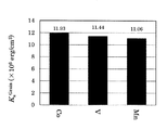
本発明者らは、V及びMnが、磁性薄膜中の酸化物相によるCoPtX合金結晶粒(磁性結晶粒)の分離性を向上させる機能を有し、粒間交換結合を低減させることができることを知見した。CoPtX−B2O3ターゲット(X=V又はMn)を用いてスパッタリングにより成膜した磁性薄膜と、CoPt−B2O3ターゲットを用いてスパッタリングにより成膜した磁性薄膜とを比較すると、隣接するCoPtX合金結晶粒の隔壁としてB2O3酸化物相が深さ方向により深く存在しており(図7:TEM観察画像)、磁化曲線における横軸(負荷磁場)と交わる地点の傾きαはより小さく(図11)、磁性結晶粒の分離性が向上していることが確認できる。一方、単位粒子当たりの結晶磁気異方性定数Kugrainは同等であり(図12)、磁性薄膜の一軸磁気異方性が良好であることが確認できる。後述する実施例から、MnよりVの方がαの低減幅が大きく、Kuの低減幅が小さいことが判明しており、Vがより好ましいといえる。
第一実施形態に係るスパッタリングターゲット中のXの含有割合は、金属相成分の全体に対して0.5mol%以上10mol%以下とすることが好ましく、1mol%以上10mol%未満がより好ましく、5mol%以下とすることが特に好ましい。Mn及びVは、それぞれ単独あるいは組み合わせて、スパッタリングターゲットの金属相成分として含有させることができる。特にMnとVとを組み合わせて用いることで、粒間交換結合をより低減させ、かつ、一軸磁気異方性を維持することができるため、好ましい。
酸化物相は、磁性薄膜のグラニュラ構造において、磁性結晶粒(微小な磁石)同士の間を仕切る非磁性マトリックスとなる。第一実施形態に係るスパッタリングターゲットの酸化物相は、少なくともBとOを含む。他の酸化物として、V、Ru、Ti、Si、Ta、Cr、Al、Nb、Mn、Co、Ni、Zn、Y、Mo、W、La、Ce、Nd、Sm、Eu、Gd、Yb、Lu、およびZrから選択される少なくとも1の元素の酸化物を含んでいてもよい。他の酸化物として具体的には、VO2、VO3、V2O5、RuO2、TiO2、SiO2、Ta2O5、Cr2O3、Al2O3、Nb2O5、MnO、Mn3O4、CoO、Co3O4、NiO、ZnO、Y2O3、MoO2、WO3、La2O3、CeO2、Nd2O3、Sm2O3、Eu2O3、Gd2O3、Yb2O3、Lu2O3およびZrO2を挙げることができる。
一般的なホウ素酸化物であるB2O3は融点が450℃と低いため、スパッタリングによる成膜過程において、析出する時期が遅く、CoPtX合金結晶粒が柱状に結晶成長している間は、柱状のCoPtX合金結晶粒の間に液体の状態で存在する。このため、最終的には、B2O3は柱状に結晶成長したCoPtX合金結晶粒同士を仕切る結晶粒界となるように析出し、磁性薄膜のグラニュラ構造において、磁性結晶粒(微小な磁石)同士の間を仕切る非磁性マトリックスとなる。磁性薄膜中の酸化物の含有量を多くした方が磁性結晶粒同士の間を確実に仕切りやすくなり、磁性結晶粒同士を独立させやすくなるので好ましい。この点から、第一実施形態に係るスパッタリングターゲット中に含まれる酸化物の含有量は25vol%以上であることが好ましく、28vol%以上であることがより好ましく、29vol%以上であることがさらに好ましい。ただし、磁性薄膜中の酸化物の含有量が多くなりすぎると、酸化物がCoPtX合金結晶粒(磁性結晶粒)中に混入して、CoPtX合金結晶粒(磁性結晶粒)の結晶性に悪影響を与えて、CoPtX合金結晶粒(磁性結晶粒)においてhcp以外の構造の割合が増えるおそれがある。また、磁性薄膜における単位面積あたりの磁性結晶粒の数が減るため、記録密度を高めにくくなる。これらの点から、第一実施形態に係るスパッタリングターゲット中に含まれる酸化物相の含有量は40vol%以下であることが好ましく、35vol%以下であることがより好ましく、31vol%以下であることがさらに好ましい。
第一実施形態に係るスパッタリングターゲットにおいて、スパッタリングターゲット全体に対する金属相成分の合計の含有割合および酸化物相成分の合計の含有割合は、目的とする磁性薄膜の成分組成によって決まり、特に限定されているわけではないが、スパッタリングターゲット全体に対する金属相成分の合計の含有割合は例えば89.4mol%以上96.4mol%以下とすることができ、スパッタリングターゲット全体に対する酸化物相成分の合計の含有割合は例えば3.6mol%以上11.6mol%以下とすることができる。
第一実施形態に係るスパッタリングターゲットのミクロ構造は特に限定されるわけではないが、金属相と酸化物相とが微細に分散し合ったミクロ構造とすることが好ましい。このようなミクロ構造とすることにより、スパッタリングを実施している際に、ノジュールやパーティクル等の不具合が発生しにくくなる。
第一実施形態に係るスパッタリングターゲットは、例えば、以下のようにして製造することができる。
所定の組成となるように各金属成分を秤量してCoPt合金溶湯を作製する。そして、ガスアトマイズを行い、CoPt合金アトマイズ粉末を作製する。作製したCoPt合金アトマイズ粉末を分級して、所定の粒径以下(例えば106μm以下)とする。
作製したCoPt合金アトマイズ粉末に、V及びMnから選択される1種以上のX金属粉末、B2O3粉末、及び必要に応じて他の酸化物粉末(例えばTiO2粉末、SiO2粉末、Ta2O5粉末、Cr2O3粉末、Al2O3粉末、ZrO2粉末、Nb2O5粉末、MnO粉末、Mn3O4粉末、CoO粉末、Co3O4粉末、NiO粉末、ZnO粉末、Y2O3粉末、MoO2粉末、WO3粉末、La2O3粉末、CeO2粉末、Nd2O3粉末、Sm2O3粉末、Eu2O3粉末、Gd2O3粉末、Yb2O3粉末、およびLu2O3粉末)を加えてボールミルで混合分散して、加圧焼結用混合粉末を作製する。CoPt合金アトマイズ粉末、X金属粉末ならびにB2O3粉末、及び必要に応じて他の酸化物粉末をボールミルで混合分散することにより、CoPt合金アトマイズ粉末、X金属粉末ならびにB2O3粉末、及び必要に応じて他の酸化物粉末が微細に分散し合った加圧焼結用混合粉末を作製することができる。
得られるスパッタリングターゲットを用いて作製される磁性薄膜において、B2O3及び必要に応じて他の酸化物によって磁性結晶粒同士の間を確実に仕切って磁性結晶粒同士を独立させやすい点、CoPtX合金結晶粒(磁性結晶粒)がhcp構造となりやすい点、および記録密度を高める点から、B2O3粉末及び必要に応じて他の酸化物粉末の合計の加圧焼結用混合粉末の全体に対する体積分率は、25vol%以上40vol%以下であることが好ましく、28vol%以上35vol%以下であることがより好ましく、29vol%以上31vol%以下であることがさらに好ましい。
作製した加圧焼結用混合粉末を、例えば真空ホットプレス法により加圧焼結して成形し、スパッタリングターゲットを作製する。加圧焼結用混合粉末はボールミルで混合分散されており、CoPt合金アトマイズ粉末と、X金属粉末と、B2O3粉末と必要に応じて他の酸化物粉末とが微細に分散し合っているので、本製造方法により得られたスパッタリングターゲットを用いてスパッタリングを行っているとき、ノジュールやパーティクルの発生等の不具合は発生しにくい。なお、加圧焼結用混合粉末を加圧焼結する方法は特に限定されず、真空ホットプレス法以外の方法でもよく、例えばHIP法等を用いてもよい。
加圧焼結用混合粉末を作製する際に、アトマイズ粉末に限定されず、各金属単体の粉末を用いてもよい。この場合には、各金属単体粉末と、B2O3粉末と、必要に応じて他の酸化物粉末と、をボールミルで混合分散して加圧焼結用混合粉末を作製することができる。
また、他の酸化物は、加圧焼結用混合粉末作製時又は焼結時に金属相の原料であるCo、V及びMnの少なくとも一部が酸化して形成されたものでもよい。
(2)第二実施形態
本発明の第二実施形態に係る磁気記録媒体用スパッタリングターゲットは、Mn及びVから選択される少なくとも1種以上、Cr及びRuから選択される少なくとも1種以上、Pt、残部がCoおよび不可避不純物からなる金属相と、少なくともBとOを含有する酸化物相と、からなることを特徴とする。
本発明の第二実施形態に係る磁気記録媒体用スパッタリングターゲットは、Mn及びVから選択される少なくとも1種以上、Cr及びRuから選択される少なくとも1種以上、Pt、残部がCoおよび不可避不純物からなる金属相と、少なくともBとOを含有する酸化物相と、からなることを特徴とする。
第二実施形態のターゲットは、Ptを1mol%以上30mol%以下、Cr及びRuから選択される少なくとも1種以上を0.5mol%超過30mol%以下、Mn及びVから選択される少なくとも1種以上を0.5mol%以上10mol%以下、残余はCo及び不可避不純物からなる金属相を含有し、磁気記録媒体用スパッタリングターゲットの全体に対して、少なくともBとOを含有する酸化物を25vol%以上40vol%以下含有することが好ましい。
BとOを含有する酸化物相とは、ホウ素酸化物を含有する相であることを意味する。ホウ素酸化物としては、B2O3が一般的であるが、BとOが非化学量論比で結合している酸化物も含まれる。しかし、非化学量論比のホウ素酸化物そのものを分析することは困難であるため、ホウ素酸化物のICP分析では同定されたBが全量B2O3であると仮定して計算している。本明細書においても、ホウ素酸化物をB2O3として説明する。
Mn及びVから選択される1種以上(以下「X」ともいう。)、Cr及びRuから選択される1種以上(以下「M」ともいう。)、Co、及びPtは、スパッタリングによって形成される磁性薄膜のグラニュラ構造において、磁性結晶粒(微小な磁石)の構成成分となる。以下、本明細書において、第二実施形態の磁性結晶粒を「CoPtXM合金結晶粒」ともいう。
Coは強磁性金属元素であり、磁性薄膜のグラニュラ構造の磁性結晶粒(微小な磁石)の形成において中心的な役割を果たす。スパッタリングによって得られる磁性薄膜中のCoPtXM合金結晶粒(磁性結晶粒)の結晶磁気異方性定数Kuを大きくするという観点および得られる磁性薄膜中のCoPtXM合金結晶粒(磁性結晶粒)の磁性を維持するという観点から、第二実施形態に係るスパッタリングターゲット中のCoの含有割合は、金属成分の全体に対して25mol%以上98mol%以下とすることが好ましい。
Ptは、所定の組成範囲でCo、X及びMと合金化することにより合金の磁気モーメントを低減させる機能を有し、磁性結晶粒の磁性の強さを調整する役割を有する。スパッタリングによって得られる磁性薄膜中のCoPtXM合金結晶粒(磁性結晶粒)の結晶磁気異方性定数Kuを大きくするという観点および得られる磁性薄膜中のCoPtXM合金結晶粒(磁性結晶粒)の磁性を調整するという観点から、第二実施形態に係るスパッタリングターゲット中のPtの含有割合は、金属相成分の全体に対して1mol%以上30mol%以下とすることが好ましい。
Cr及びRuから選択される少なくとも1種以上は、所定の組成範囲でCoと合金化することによりCoの磁気モーメントを低下させる機能を有し、磁性結晶粒の磁性の強さを調整する役割を有する。スパッタリングによって得られる磁性薄膜中のCoPtXM合金結晶粒(磁性結晶粒)の結晶磁気異方性定数Kuを大きくするという観点および得られる磁性薄膜中のCoPtXM合金結晶粒の磁性を維持するという観点から、第二実施形態に係るスパッタリングターゲット中のCr及びRuから選択される少なくとも1種以上の含有割合は、金属相成分の全体に対して0.5mol%超過30mol%以下とすることが好ましい。Cr及びRuは、それぞれ単独あるいは組み合わせて用いることができ、Co及びPtと共にスパッタリングターゲットの金属相を形成する。後述する実施例から、CrよりRuの方がKuの低下幅を小さくできることが判明したことから、Ruがより好ましいといえる。
本発明者らは、V及びMnが磁性薄膜中の酸化物相によるCoPtXM合金結晶粒(磁性結晶粒)の分離性を向上させる機能を有し、粒間交換結合を低減させることができることを知見した。一方で、結晶磁気異方性定数Kuを大きく低減させることはない。後述する実施例から、MnよりVの方がαの低減幅が大きく、Kuの低減幅が小さいことが判明しており、Vがより好ましいといえる。
第二実施形態に係るスパッタリングターゲット中のXの含有割合は、金属相成分の全体に対して0.5mol%以上10mol%以下とすることが好ましく、1mol%以上10mol%未満がより好ましく、5mol%以下とすることが特に好ましい。Mn及びVは、それぞれ単独あるいは組み合わせて、スパッタリングターゲットの金属相成分として含有させることができる。特にVとMnとを組み合わせて用いることで、粒間交換結合を低減させ、かつ、一軸磁気異方性を向上させることができるため、好ましい。
酸化物相は、磁性薄膜のグラニュラ構造において、磁性結晶粒(微小な磁石)同士の間を仕切る非磁性マトリックスとなる。第二実施形態に係るスパッタリングターゲットの酸化物相は、少なくともBとOを含む。他の酸化物成分として、V、Ru、Ti、Si、Ta、Cr、Al、Nb、Mn、Co、Ni、Zn、Y、Mo、W、La、Ce、Nd、Sm、Eu、Gd、Yb、Lu、およびZrから選択される少なくとも1の元素の酸化物を含んでいてもよい。他の酸化物として具体的には、VO2、VO3、V2O5、RuO2、TiO2、SiO2、Ta2O5、Cr2O3、Al2O3、Nb2O5、MnO、Mn3O4、CoO、Co3O4、NiO、ZnO、Y2O3、MoO2、WO3、La2O3、CeO2、Nd2O3、Sm2O3、Eu2O3、Gd2O3、Yb2O3、Lu2O3およびZrO2を挙げることができる。
一般的なホウ素酸化物であるB2O3は融点が450℃と低いため、スパッタリングによる成膜過程において、析出する時期が遅く、CoPtXM合金結晶粒が柱状に結晶成長している間は、柱状のCoPtXM合金結晶粒の間に液体の状態で存在する。このため、最終的には、B2O3は柱状に結晶成長したCoPtXM合金結晶粒同士を仕切る結晶粒界となるように析出し、磁性薄膜のグラニュラ構造において、磁性結晶粒(微小な磁石)同士の間を仕切る非磁性マトリックスとなる。磁性薄膜中の酸化物の含有量を多くした方が磁性結晶粒同士の間を確実に仕切りやすくなり、磁性結晶粒同士を独立させやすくなるので好ましい。この点から、第二実施形態に係るスパッタリングターゲット中に含まれる酸化物の含有量は25vol%以上であることが好ましく、28vol%以上であることがより好ましく、29vol%以上であることがさらに好ましい。ただし、磁性薄膜中の酸化物の含有量が多くなりすぎると、酸化物がCoPtXM合金結晶粒(磁性結晶粒)中に混入して、CoPtXM合金結晶粒(磁性結晶粒)の結晶性に悪影響を与えて、CoPtXM合金結晶粒(磁性結晶粒)においてhcp以外の構造の割合が増えるおそれがある。また、磁性薄膜における単位面積あたりの磁性結晶粒の数が減るため、記録密度を高めにくくなる。これらの点から、第二実施形態に係るスパッタリングターゲット中に含まれる酸化物相の含有量は40vol%以下であることが好ましく、35vol%以下であることがより好ましく、31vol%以下であることがさらに好ましい。
第二実施形態に係るスパッタリングターゲットにおいて、スパッタリングターゲット全体に対する金属相成分の合計の含有割合および酸化物相成分の合計の含有割合は、目的とする磁性薄膜の成分組成によって決まり、特に限定されているわけではないが、スパッタリングターゲット全体に対する金属相成分の合計の含有割合は例えば88.2mol%以上96.4mol%以下とすることができ、スパッタリングターゲット全体に対する酸化物相成分の合計の含有割合は例えば3.6mol%以上11.8mol%以下とすることができる。
第二実施形態に係るスパッタリングターゲットのミクロ構造は特に限定されるわけではないが、金属相と酸化物相とが微細に分散し合ったミクロ構造とすることが好ましい。このようなミクロ構造とすることにより、スパッタリングを実施している際に、ノジュールやパーティクル等の不具合が発生しにくくなる。
第二実施形態に係るスパッタリングターゲットは、例えば、以下のようにして製造することができる。
所定の組成となるように、Cr及びRuから選択される1種以上のM金属粉末、Co及びPtを秤量してCoPtM合金溶湯を作製する。そして、ガスアトマイズを行い、CoPtM合金アトマイズ粉末を作製する。作製したCoPtM合金アトマイズ粉末を分級して、所定の粒径以下(例えば106μm以下)とする。
作製したCoPtM合金アトマイズ粉末に、V及びMnから選択される1種以上のX金属粉末、B2O3粉末、及び必要に応じて他の酸化物粉末(例えばTiO2粉末、SiO2粉末、Ta2O5粉末、Cr2O3粉末、Al2O3粉末、ZrO2粉末、Nb2O5粉末、MnO粉末、Mn3O4粉末、CoO粉末、Co3O4粉末、NiO粉末、ZnO粉末、Y2O3粉末、MoO2粉末、WO3粉末、La2O3粉末、CeO2粉末、Nd2O3粉末、Sm2O3粉末、Eu2O3粉末、Gd2O3粉末、Yb2O3粉末、およびLu2O3粉末)を加えてボールミルで混合分散して、加圧焼結用混合粉末を作製する。CoPtM合金アトマイズ粉末、X金属粉末及びB2O3粉末並びに必要に応じて他の酸化物粉末をボールミルで混合分散することにより、CoPtM合金アトマイズ粉末、X金属粉末及びB2O3粉末、並びに必要に応じて他の酸化物粉末が微細に分散し合った加圧焼結用混合粉末を作製することができる。
得られるスパッタリングターゲットを用いて作製される磁性薄膜において、B2O3及び必要に応じて他の酸化物によって磁性結晶粒同士の間を確実に仕切って磁性結晶粒同士を独立させやすい点、CoPtXM合金結晶粒(磁性結晶粒)がhcp構造となりやすい点、および記録密度を高める点から、B2O3粉末及び必要に応じて他の酸化物粉末の合計の加圧焼結用混合粉末の全体に対する体積分率は、25vol%以上40vol%以下であることが好ましく、28vol%以上35vol%以下であることがより好ましく、29vol%以上31vol%以下であることがさらに好ましい。
作製した加圧焼結用混合粉末を、例えば真空ホットプレス法により加圧焼結して成形し、スパッタリングターゲットを作製する。加圧焼結用混合粉末はボールミルで混合分散されており、CoPtM合金アトマイズ粉末とX金属粉末とB2O3粉末と必要に応じて他の酸化物粉末とが微細に分散し合っているので、本製造方法により得られたスパッタリングターゲットを用いてスパッタリングを行っているとき、ノジュールやパーティクルの発生等の不具合は発生しにくい。なお、加圧焼結用混合粉末を加圧焼結する方法は特に限定されず、真空ホットプレス法以外の方法でもよく、例えばHIP法等を用いてもよい。
加圧焼結用混合粉末を作製する際に、アトマイズ粉末に限定されず、各金属単体の粉末を用いてもよい。この場合には、各金属単体粉末と、必要に応じてB粉末と、B2O3粉末と、必要に応じて他の酸化物粉末と、をボールミルで混合分散して加圧焼結用混合粉末を作製することができる。
また、他の酸化物は、加圧焼結用混合粉末作製時又は焼結時に金属相の原料であるCo、Cr、Ru、V及びMnの少なくとも一部が酸化して形成されたものでもよい。
(3)第三実施形態
本発明の第三実施形態に係る磁気記録媒体用スパッタリングターゲットは、Mn及びVから選択される少なくとも1種以上、Pt、残部がCoおよび不可避不純物からなる金属相と、酸化物相と、からなることを特徴とする。
本発明の第三実施形態に係る磁気記録媒体用スパッタリングターゲットは、Mn及びVから選択される少なくとも1種以上、Pt、残部がCoおよび不可避不純物からなる金属相と、酸化物相と、からなることを特徴とする。
第三実施形態のターゲットは、Ptを1mol%以上30mol%以下、Mn及びVから選択される少なくとも1種以上を0.5mol%以上10mol%以下、残余はCo及び不可避不純物からなる金属相を含有し、磁気記録媒体用スパッタリングターゲットの全体に対して、酸化物を25vol%以上40vol%以下含有することが好ましい。
第三実施形態は、酸化物相がホウ素酸化物を含むものに限定されない点を除いて第一実施形態と同様であるため、説明は割愛し、ホウ素酸化物を含む酸化物相に限定されない理由を説明する。
後述する実施例により明かなように、金属相がV又はMnを含むものであれば、酸化物としてホウ素酸化物を含まないものでも、Kuの低減が少なく、αが低下することが判明している。酸化物としてSiO2及びTiO2を含む場合には、αが低下するのみではなくKuも増加するので特に好ましい。酸化物として、SiO2、TiO2、Cr2O3、Nb2O5、Ta2O5、MoO3、WO3、CoO、B2O3及びこれらの任意の組み合わせを用いる場合に、αが低下し、Kuの低下は小さいことが確認できている。酸化物は、柱状に結晶成長したCoPtX合金結晶粒同士を仕切る結晶粒界となるように析出し、磁性薄膜のグラニュラ構造において、磁性結晶粒(微小な磁石)同士の間を仕切る非磁性マトリックスとなる。
第三実施形態に係る磁気記録媒体用スパッタリングターゲットは、上述した酸化物に加えて、V、Ru、Al、Mn、Co、Ni、Zn、Y、Mo、La、Ce、Nd、Sm、Eu、Gd、Yb、Lu、およびZrから選択される少なくとも1の元素の酸化物をさらに含んでいてもよい。他の酸化物として具体的には、VO2、VO3、V2O5、RuO2、Al2O3、MnO、Mn3O4、Co3O4、NiO、ZnO、Y2O3、MoO2、La2O3、CeO2、Nd2O3、Sm2O3、Eu2O3、Gd2O3、Yb2O3、Lu2O3およびZrO2を挙げることができる。
(4)第四実施形態
本発明の第四実施形態に係る磁気記録媒体用スパッタリングターゲットは、Mn及びVから選択される少なくとも1種以上、Cr及びRuから選択される少なくとも1種以上、Pt、残部がCoおよび不可避不純物からなる金属相と、酸化物相と、からなることを特徴とする。
本発明の第四実施形態に係る磁気記録媒体用スパッタリングターゲットは、Mn及びVから選択される少なくとも1種以上、Cr及びRuから選択される少なくとも1種以上、Pt、残部がCoおよび不可避不純物からなる金属相と、酸化物相と、からなることを特徴とする。
第四実施形態のターゲットは、Ptを1mol%以上30mol%以下、Cr及びRuから選択される少なくとも1種以上を0.5mol%超過30mol%以下、Mn及びVから選択される少なくとも1種以上を0.5mol%以上10mol%以下、残余はCo及び不可避不純物からなる金属相を含有し、磁気記録媒体用スパッタリングターゲットの全体に対して、酸化物を25vol%以上40vol%以下含有することが好ましい。
第四実施形態は、ホウ素酸化物を含む酸化物相に限定されない点を除いて第二実施形態と同様であり、また、任意の酸化物を含み得る点については第三実施形態と同様であるため、説明は割愛する。
以下、実施例及び比較例を用いて本発明をさらに説明する。
(実施例1)
実施例1として作製したターゲット全体の組成は、(75Co−20Pt−5V)−30vol%B2O3(金属成分については原子比で示す)であり、モル比で表すと、92.47(75Co−20Pt−5V)−7.53B2O3である。
実施例1として作製したターゲット全体の組成は、(75Co−20Pt−5V)−30vol%B2O3(金属成分については原子比で示す)であり、モル比で表すと、92.47(75Co−20Pt−5V)−7.53B2O3である。
実施例1に係るターゲットの作製に際しては、まず、50Co−50Pt合金および100Coアトマイズ粉を作製した。具体的には、合金アトマイズ粉は組成がCo:50at%、Pt:50at%となるように各金属を秤量し、両組成とも1500℃以上に加熱して合金溶湯とし、ガスアトマイズを行ってそれぞれ50Co−50Pt合金、100Coアトマイズ粉末を作製した。
作製した50Co−50Pt合金および100Coアトマイズ粉末を150メッシュのふるいで分級して、それぞれ粒径が106μm以下の50Co−50Pt合金および100Coアトマイズ粉末を得た。
(75Co−20Pt−5V)−30vol%B2O3の組成となるように、分級後の50Co−50Pt合金と100Coアトマイズ粉末に、V粉末、およびB2O3粉末を添加してボールミルで混合分散を行い、加圧焼結用混合粉末を得た。
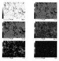
得られた加圧焼結用混合粉末を用いて、焼結温度:810℃、焼結圧力:24.5MPa、焼結時間:30分、雰囲気:5×10⁻²Pa以下の真空条件でホットプレスを行い、焼結体テストピース(φ30mm)を作製した。作製した焼結体テストピースの相対密度は98.8%であった。なお、計算密度は8.90g/cm3である。得られた焼結体テストピースの厚さ方向断面を鏡面研磨し、走査型電子顕微鏡(SEM:JEOL製JCM−6000Plus)を用い加速電圧15keVにて観察した結果を図1に示す。また同装置に設置されたエネルギー分散型X線分光器(EDS)を用いて断面組織の組成分析を行った結果を図2に示す。これらの結果により金属相(75Co−20Pt−5V合金相)と酸化物相(B2O3)とは微細に分散されていることが確認できた。得られた焼結体テストピースをICP分析した結果を表3に示す。
次に、作製した加圧焼結用混合粉末を用いて、焼結温度:810℃、焼結圧力:24.5MPa、焼結時間:60分、雰囲気:5×10⁻²Pa以下の真空条件でホットプレスを行い、φ153.0×1.0mm+φ161.0×4.0mmのターゲットを1つ作製した。作製したターゲットの相対密度は98.3%であった。
作製したターゲットを用いてDCスパッタ装置(エイコーエンジニアリング製ES−3100W)でスパッタリングを行い、(75Co−20Pt−5V)−30vol%B2O3からなる磁性薄膜をガラス基板上に成膜させ、磁気特性測定用サンプルおよび組織観察用サンプルを作製した。具体的には、ガラス基板と金属膜との密着性を確保するための層としてTaをArガス圧0.6Pa、投入電力500Wの条件で5nm成膜した。次に、配向膜を形成するためのシード層としてNi90W10を0.6Pa、500Wで6nm成膜した。続いて、hcp構造下地としてRuを0.6Pa、500Wで10nm成膜した後、表面凹凸形状を形成する為にRuを8.0Pa、500Wで10nm成膜した。さらに、磁性コラムの分離性をよくする目的でCo−25Cr−50Ru−30vol%TiO2を0.6Pa、300Wで1nm成膜した。その上に、磁性層として(Co−20Pt−5V)−30vol%B2O3を4.0Pa、500Wでそれぞれ4nm、8nm、12nm、16nm成膜した。最後に、表面保護層としてCを0.6Pa、300Wで7nm成膜した。これらのサンプルの層構成は、ガラス基板に近い方から順に表示して、Ta(5nm,0.6Pa)/Ni90W10(6nm,0.6Pa)/Ru(10nm,0.6Pa)/Ru(10nm,8.0Pa)/Co−25Cr−50Ru−30vol%TiO2(1nm、4.0Pa)/(Co−20Pt−5V)−30vol%B2O3(Ynm(Y=4、8、12又は16),4Pa)/C(7nm,0.6Pa)である。括弧内の左側の数字は膜厚を示し、右側の数字はスパッタリングを行ったときのAr雰囲気の圧力を示す。実施例1で作製したターゲットを用いて成膜した磁性薄膜はCoPtV合金−酸化物(B2O3)であり、垂直磁気記録媒体の記録層となる磁性薄膜である。なお、この磁性薄膜を成膜する際には基板は昇温させておらず、室温で成膜した。
得られた磁気特性測定用サンプルの磁気特性の測定には、振動試料型磁力計(VSM:(株)玉川製作所製 TM−VSM211483−HGC型)、トルク磁力計((株)玉川製作所製 TM−TR2050−HGC型)及び極カー効果測定装置(MOKE:ネオアーク(株)製 BH−810CPM−CPC)を用いた。
実施例1の磁気特性測定用サンプルのグラニュラ媒体磁化曲線の一例(Y=12nm)を図3に示す。図3の横軸は加えた磁場の強さであり、図3の縦軸は単位体積当たりの磁化の強さである。
磁気特性測定用サンプルのグラニュラ媒体磁化曲線の測定結果から、飽和磁化(Ms)、保磁力(Hc)、逆磁区核形成磁界(Hn)、横軸と交わる地点の傾き(α)を求めた。また、結晶磁気異方性定数(Ku)はトルク磁力計を用いて測定した。それらの値を、他の実施例および比較例の結果と合わせて表1、図8~12に示す。
また、得られた組織観察用サンプルの構造の評価(磁性結晶粒の粒径等の評価)には、X線回折装置(XRD:((株)リガク製 SmartLab)および透過電子顕微鏡(TEM:(株)日立ハイテクノロジーズ製 H−9500)を用いた。膜面垂直方向のXRDプロファイルを図6及び表2、TEM画像を図7に示す。
(実施例2)
実施例2として作製したターゲット全体の組成は、(75Co−20Pt−5Mn)−30vol%B2O3(金属成分については原子比で示す)であり、モル比で表すと、92.51(75Co−20Pt−5Mn)−7.49B2O3である。ターゲットの組成を実施例1から変更した以外は、実施例1と同様にして磁気特性測定用サンプルおよび組織観察用サンプルを作製して観察を行った。結果を図4及び図5に示す。用いたMn粉末は平均粒径3μm以下であり、焼結温度:840℃、焼結圧力:24.5MPa、焼結時間:30分、雰囲気:5×10⁻²Pa以下の真空条件でホットプレスを行い、焼結体テストピース(φ30mm)を作製した。作製した焼結体テストピースの相対密度は102.6%であった。なお、計算密度は8.97g/cm3である。得られた焼結体テストピースの厚さ方向断面を金属顕微鏡で観察したところ、金属相(75Co−20Pt−5Mn合金相)と酸化物相(B2O3)とは微細に分散されていることが確認できた。得られた焼結体テストピースをICP分析した結果を表3に示す。
実施例2として作製したターゲット全体の組成は、(75Co−20Pt−5Mn)−30vol%B2O3(金属成分については原子比で示す)であり、モル比で表すと、92.51(75Co−20Pt−5Mn)−7.49B2O3である。ターゲットの組成を実施例1から変更した以外は、実施例1と同様にして磁気特性測定用サンプルおよび組織観察用サンプルを作製して観察を行った。結果を図4及び図5に示す。用いたMn粉末は平均粒径3μm以下であり、焼結温度:840℃、焼結圧力:24.5MPa、焼結時間:30分、雰囲気:5×10⁻²Pa以下の真空条件でホットプレスを行い、焼結体テストピース(φ30mm)を作製した。作製した焼結体テストピースの相対密度は102.6%であった。なお、計算密度は8.97g/cm3である。得られた焼結体テストピースの厚さ方向断面を金属顕微鏡で観察したところ、金属相(75Co−20Pt−5Mn合金相)と酸化物相(B2O3)とは微細に分散されていることが確認できた。得られた焼結体テストピースをICP分析した結果を表3に示す。
次に、作製した加圧焼結用混合粉末を用いて、焼結温度:840℃、焼結圧力:24.5MPa、焼結時間:60min、雰囲気:5×10⁻²Pa以下の真空条件でホットプレスを行い、φ153.0×1.0mm+φ161.0×4.0mmのターゲットを1つ作製した。作製したターゲットの相対密度は104.8%であった。
次に実施例1と同様に膜に関する磁気特性の評価及び組織観察を行った。磁気特性の測定結果をターゲットの組成とともに表1、図8~12に示す。また、組織観察の膜面垂直方向のXRDプロファイルを図6及び表2、TEM画像を図7に示す。
(比較例1)
ターゲット全体の組成を(80Co−20Pt)−30vol%B2O3(金属成分については原子比で示す)として、実施例1及び2と同様に焼結体テストピース及びターゲットを作製し、磁性薄膜を成膜し、評価した。磁気特性の測定結果をターゲットの組成とともに表1、図8~12に示し、組織観察の膜面垂直方向のXRDプロファイルを図6に示し、XRDプロファイルから読み取れるCoPt(002)のピーク位置(2θ)及びC軸の格子定数を表2に示し、TEM画像を図7に示す。得られた焼結体テストピースをICP分析した結果を表3に示す。
ターゲット全体の組成を(80Co−20Pt)−30vol%B2O3(金属成分については原子比で示す)として、実施例1及び2と同様に焼結体テストピース及びターゲットを作製し、磁性薄膜を成膜し、評価した。磁気特性の測定結果をターゲットの組成とともに表1、図8~12に示し、組織観察の膜面垂直方向のXRDプロファイルを図6に示し、XRDプロファイルから読み取れるCoPt(002)のピーク位置(2θ)及びC軸の格子定数を表2に示し、TEM画像を図7に示す。得られた焼結体テストピースをICP分析した結果を表3に示す。
表1の略記号の意味は以下のとおりである。
tMag1:積層膜のうち磁気記録層の膜厚
Ms Grain:積層膜の磁性層のうち磁性粒子のみの飽和磁化
Hc:Kerrで測定した保磁力
Hn:Kerrで測定した核形成磁場
α:Kerrで測定した磁化曲線における横軸(負荷磁場)と交わる地点の傾き
Hc−Hn:Kerrで測定した保磁力と核形成磁場の差
Ku Grain:積層膜の磁性層のうち磁性粒子のみの結晶磁気異方性定数
tMag1:積層膜のうち磁気記録層の膜厚
Ms Grain:積層膜の磁性層のうち磁性粒子のみの飽和磁化
Hc:Kerrで測定した保磁力
Hn:Kerrで測定した核形成磁場
α:Kerrで測定した磁化曲線における横軸(負荷磁場)と交わる地点の傾き
Hc−Hn:Kerrで測定した保磁力と核形成磁場の差
Ku Grain:積層膜の磁性層のうち磁性粒子のみの結晶磁気異方性定数

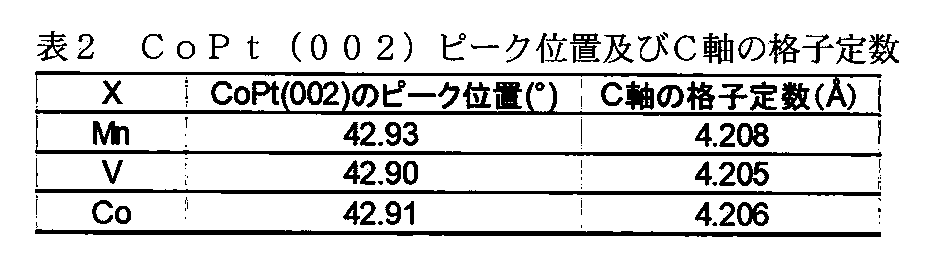
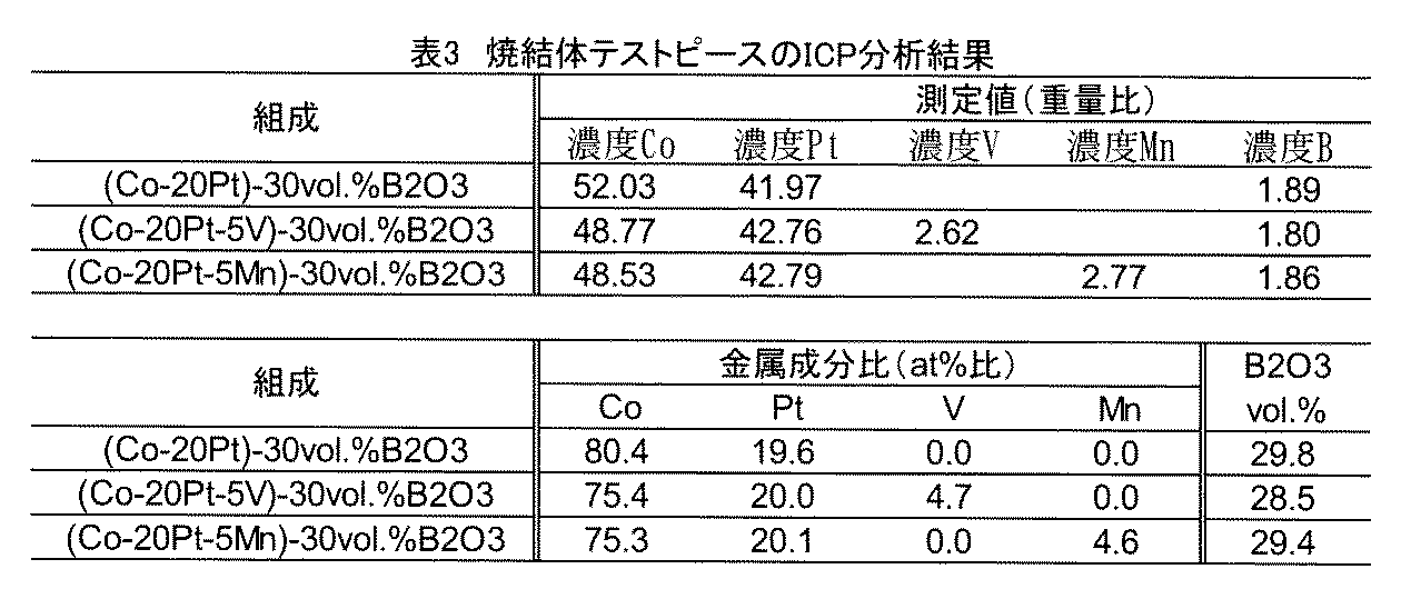
図6及び表2より、実施例1(V)及び実施例2(Mn)は、比較例1(Co)よりもCoPt(002)ピークが低角へシフトしていることが確認できる。このことから、V又はMnの少なくとも一部はCoと置換しているといえる。しかしながら、ピーク位置から計算されるCoPt相のC軸の格子定数の変化は0.1Å以下である。また、CoPt相の構造変化は確認されない。一方、Ru及びNiWについてはピークのシフトは確認されない。
図7より、V又はMnを含む磁性薄膜は、V又はMnを含まない磁性薄膜(X=Co)と比較すると、隣接する磁性カラムの間の隙間が深さ方向により深く延在している様子が確認できる。このことから、V又はMnを含むターゲットを用いることで、磁性結晶粒の分離性が向上していることが確認できる。
図8より、比較例1(Co)に対して、成膜4nmの場合に実施例1(V)及び実施例2(Mn)では若干のMsの増大が確認されるが、成膜8nm以上ではほぼ同等であり、CoPtX合金結晶粒(磁性結晶粒)の磁性を維持できることがわかる。
図9より、V又はMnを含む磁性薄膜は、V又はMnを含まない磁性薄膜(X=Co)と比較すると、同等程度または僅かに低いHcを示している。しかし、組成の最適化やVとMnを組み合わせて投入することなどにより更なる向上が見込める。
図10より、比較例1(Co)に対して、実施例1(V)ではHnの低下が確認される。実施例2(Mn)では実施例1(V)よりも更なるHnの低下が確認される。このことは磁性結晶粒の分離性が向上していることを示唆している。
図11より、V又はMnを含む磁性薄膜は、V又はMnを含まない磁性薄膜(X=Co)と比較して低いαを示しており、磁性結晶粒の分離性が向上していることが確認できる。
図12より、V又はMnを含む磁性薄膜は、V又はMnを含まない磁性薄膜(X=Co)と比較して同等のKuを示しており、高い一軸磁気異方性を維持していることが確認できる。
(実施例3~4、比較例2)
酸化物相を30vol%SiO2に代えた以外は実施例1~2及び比較例1と同様にして調製した磁気記録媒体用スパッタリングターゲットを用いて、実施例1と同様にして厚さ8nmの磁性層を成膜させ、保磁力(Hc)、核形成磁場(Hn)、横軸と交わる地点の傾き(α)、結晶磁気異方性定数(Ku)を測定した。結果を表4に示す。
酸化物相を30vol%SiO2に代えた以外は実施例1~2及び比較例1と同様にして調製した磁気記録媒体用スパッタリングターゲットを用いて、実施例1と同様にして厚さ8nmの磁性層を成膜させ、保磁力(Hc)、核形成磁場(Hn)、横軸と交わる地点の傾き(α)、結晶磁気異方性定数(Ku)を測定した。結果を表4に示す。
金属相にV又はMnを含み、酸化物相としてSiO2を含む実施例3~4は、比較例2よりもαが低減し、Kuが増加しており、磁性結晶粒の分離性が向上し、高い一軸磁気異方性を示すといえる。
(実施例5~6、比較例3)
酸化物相を30vol%TiO2に代えた以外は実施例1~2及び比較例1と同様にして調製した磁気記録媒体用スパッタリングターゲットを用いて、実施例1と同様にして厚さ8nmの磁性層を成膜させ、保磁力(Hc)、核形成磁場(Hn)、横軸と交わる地点の傾き(α)、結晶磁気異方性定数(Ku)を測定した。結果を表4に示す。
酸化物相を30vol%TiO2に代えた以外は実施例1~2及び比較例1と同様にして調製した磁気記録媒体用スパッタリングターゲットを用いて、実施例1と同様にして厚さ8nmの磁性層を成膜させ、保磁力(Hc)、核形成磁場(Hn)、横軸と交わる地点の傾き(α)、結晶磁気異方性定数(Ku)を測定した。結果を表4に示す。
金属相にV又はMnを含み、酸化物相としてTiO2を含む実施例5~6は、比較例3よりもαが低減し、Kuが増加しており、磁性結晶粒の分離性が向上し、高い一軸磁気異方性を示すといえる。
(実施例7~8、比較例4)
酸化物相を30vol%Cr2O3に代えた以外は実施例1~2及び比較例1と同様にして調製した磁気記録媒体用スパッタリングターゲットを用いて、実施例1と同様にして厚さ8nmの磁性層を成膜させ、保磁力(Hc)、核形成磁場(Hn)、横軸と交わる地点の傾き(α)、結晶磁気異方性定数(Ku)を測定した。結果を表4に示す。
酸化物相を30vol%Cr2O3に代えた以外は実施例1~2及び比較例1と同様にして調製した磁気記録媒体用スパッタリングターゲットを用いて、実施例1と同様にして厚さ8nmの磁性層を成膜させ、保磁力(Hc)、核形成磁場(Hn)、横軸と交わる地点の傾き(α)、結晶磁気異方性定数(Ku)を測定した。結果を表4に示す。
金属相にV又はMnを含み、酸化物相としてCr2O3を含む実施例7~8は、比較例4よりもαが低減し、Kuの低下は0.95以下と小さく、磁性結晶粒の分離性が向上し、高い一軸磁気異方性を維持しているといえる。
(実施例9~10、比較例5)
酸化物相を30vol%Nb2O5に代えた以外は実施例1~2及び比較例1と同様にして調製した磁気記録媒体用スパッタリングターゲットを用いて、実施例1と同様にして厚さ8nmの磁性層を成膜させ、保磁力(Hc)、核形成磁場(Hn)、横軸と交わる地点の傾き(α)、結晶磁気異方性定数(Ku)を測定した。結果を表4に示す。
酸化物相を30vol%Nb2O5に代えた以外は実施例1~2及び比較例1と同様にして調製した磁気記録媒体用スパッタリングターゲットを用いて、実施例1と同様にして厚さ8nmの磁性層を成膜させ、保磁力(Hc)、核形成磁場(Hn)、横軸と交わる地点の傾き(α)、結晶磁気異方性定数(Ku)を測定した。結果を表4に示す。
金属相にV又はMnを含み、酸化物相としてNb2O5を含む実施例9~10は、比較例5よりもαが低減し、Kuの低下は0.39以下と小さく、磁性結晶粒の分離性が向上し、高い一軸磁気異方性を維持しているといえる。
(実施例11~12、比較例6)
酸化物相を30vol%Ta2O5に代えた以外は実施例1~2及び比較例1と同様にして調製した磁気記録媒体用スパッタリングターゲットを用いて、実施例1と同様にして厚さ8nmの磁性層を成膜させ、保磁力(Hc)、核形成磁場(Hn)、横軸と交わる地点の傾き(α)、結晶磁気異方性定数(Ku)を測定した。結果を表4に示す。
酸化物相を30vol%Ta2O5に代えた以外は実施例1~2及び比較例1と同様にして調製した磁気記録媒体用スパッタリングターゲットを用いて、実施例1と同様にして厚さ8nmの磁性層を成膜させ、保磁力(Hc)、核形成磁場(Hn)、横軸と交わる地点の傾き(α)、結晶磁気異方性定数(Ku)を測定した。結果を表4に示す。
金属相にV又はMnを含み、酸化物相としてTa2O5を含む実施例11~12は、比較例6よりもαが低減し、Kuの低下は0.47以下と小さく、磁性結晶粒の分離性が向上し、高い一軸磁気異方性を維持しているといえる。
(実施例13~14、比較例7)
酸化物相を30vol%MoO3に代えた以外は実施例1~2及び比較例1と同様にして調製した磁気記録媒体用スパッタリングターゲットを用いて、実施例1と同様にして厚さ8nmの磁性層を成膜させ、保磁力(Hc)、核形成磁場(Hn)、横軸と交わる地点の傾き(α)、結晶磁気異方性定数(Ku)を測定した。結果を表5に示す。
酸化物相を30vol%MoO3に代えた以外は実施例1~2及び比較例1と同様にして調製した磁気記録媒体用スパッタリングターゲットを用いて、実施例1と同様にして厚さ8nmの磁性層を成膜させ、保磁力(Hc)、核形成磁場(Hn)、横軸と交わる地点の傾き(α)、結晶磁気異方性定数(Ku)を測定した。結果を表5に示す。
金属相にV又はMnを含み、酸化物相としてMoO3を含む実施例13~14は、比較例7よりもαが低減し、Kuの低下は0.30以下と小さく、磁性結晶粒の分離性が向上し、高い一軸磁気異方性を維持しているといえる。
(実施例15~16、比較例8)
酸化物相を30vol%WO3に代えた以外は実施例1~2及び比較例1と同様にして調製した磁気記録媒体用スパッタリングターゲットを用いて、実施例1と同様にして厚さ8nmの磁性層を成膜させ、保磁力(Hc)、核形成磁場(Hn)、横軸と交わる地点の傾き(α)、結晶磁気異方性定数(Ku)を測定した。結果を表5に示す。
酸化物相を30vol%WO3に代えた以外は実施例1~2及び比較例1と同様にして調製した磁気記録媒体用スパッタリングターゲットを用いて、実施例1と同様にして厚さ8nmの磁性層を成膜させ、保磁力(Hc)、核形成磁場(Hn)、横軸と交わる地点の傾き(α)、結晶磁気異方性定数(Ku)を測定した。結果を表5に示す。
金属相にV又はMnを含み、酸化物相としてWO3を含む実施例15~16は、比較例8よりもαが低減し、Kuの低下は0.51以下と小さく、磁性結晶粒の分離性が向上し、高い一軸磁気異方性を維持しているといえる。
(実施例17~18、比較例9)
酸化物相を15vol%B2O3−15vol%SiO2に代えた以外は実施例1~2及び比較例1と同様にして調製した磁気記録媒体用スパッタリングターゲットを用いて、実施例1と同様にして厚さ8nmの磁性層を成膜させ、保磁力(Hc)、核形成磁場(Hn)、横軸と交わる地点の傾き(α)、結晶磁気異方性定数(Ku)を測定した。結果を表5に示す。
酸化物相を15vol%B2O3−15vol%SiO2に代えた以外は実施例1~2及び比較例1と同様にして調製した磁気記録媒体用スパッタリングターゲットを用いて、実施例1と同様にして厚さ8nmの磁性層を成膜させ、保磁力(Hc)、核形成磁場(Hn)、横軸と交わる地点の傾き(α)、結晶磁気異方性定数(Ku)を測定した。結果を表5に示す。
金属相にV又はMnを含み、酸化物相としてB2O3及びSiO2を含む実施例17~18は、比較例9よりもαが低減し、Kuの低下は0.18以下と小さく、磁性結晶粒の分離性が向上し、高い一軸磁気異方性を維持しているといえる。
(実施例19~20、比較例10)
酸化物相を15vol%SiO2−15vol%TiO2に代えた以外は実施例1~2及び比較例1と同様にして調製した磁気記録媒体用スパッタリングターゲットを用いて、実施例1と同様にして厚さ8nmの磁性層を成膜させ、保磁力(Hc)、核形成磁場(Hn)、横軸と交わる地点の傾き(α)、結晶磁気異方性定数(Ku)を測定した。結果を表5に示す。
酸化物相を15vol%SiO2−15vol%TiO2に代えた以外は実施例1~2及び比較例1と同様にして調製した磁気記録媒体用スパッタリングターゲットを用いて、実施例1と同様にして厚さ8nmの磁性層を成膜させ、保磁力(Hc)、核形成磁場(Hn)、横軸と交わる地点の傾き(α)、結晶磁気異方性定数(Ku)を測定した。結果を表5に示す。
金属相にV又はMnを含み、酸化物相としてSiO2及びTiO2を含む実施例19~20は、比較例10よりもαが低減し、Kuは増加又は0.01の低下と非常に小さく、磁性結晶粒の分離性が向上し、高い一軸磁気異方性を示すといえる。
(実施例21~22、比較例11)
酸化物相を20vol%B2O3−5vol%Cr2O3に代えた以外は実施例1~2及び比較例1と同様にして調製した磁気記録媒体用スパッタリングターゲットを用いて、実施例1と同様にして厚さ8nmの磁性層を成膜させ、保磁力(Hc)、核形成磁場(Hn)、横軸と交わる地点の傾き(α)、結晶磁気異方性定数(Ku)を測定した。結果を表5に示す。
酸化物相を20vol%B2O3−5vol%Cr2O3に代えた以外は実施例1~2及び比較例1と同様にして調製した磁気記録媒体用スパッタリングターゲットを用いて、実施例1と同様にして厚さ8nmの磁性層を成膜させ、保磁力(Hc)、核形成磁場(Hn)、横軸と交わる地点の傾き(α)、結晶磁気異方性定数(Ku)を測定した。結果を表5に示す。
金属相にV又はMnを含み、酸化物相としてB2O3及びCr2O3を含む実施例21~22は、比較例11よりもαが低減し、Kuの低下は0.54以下と小さく、磁性結晶粒の分離性が向上し、高い一軸磁気異方性を維持しているといえる。
(実施例23~24、比較例12)
酸化物相を10vol%SiO2−10vol%TiO2−10vol%CoOに代えた以外は実施例1~2及び比較例1と同様にして調製した磁気記録媒体用スパッタリングターゲットを用いて、実施例1と同様にして厚さ8nmの磁性層を成膜させ、保磁力(Hc)、核形成磁場(Hn)、横軸と交わる地点の傾き(α)、結晶磁気異方性定数(Ku)を測定した。結果を表5に示す。
酸化物相を10vol%SiO2−10vol%TiO2−10vol%CoOに代えた以外は実施例1~2及び比較例1と同様にして調製した磁気記録媒体用スパッタリングターゲットを用いて、実施例1と同様にして厚さ8nmの磁性層を成膜させ、保磁力(Hc)、核形成磁場(Hn)、横軸と交わる地点の傾き(α)、結晶磁気異方性定数(Ku)を測定した。結果を表5に示す。
金属相にV又はMnを含み、酸化物相としてSiO2、TiO2及びCoOを含む実施例23~24は、比較例12よりもαが低減し、Kuの低下は0.35と小さく、磁性結晶粒の分離性が向上し、高い一軸磁気異方性を示すといえる。
(実施例25~26、比較例13)
酸化物相を20vol%SiO2−5vol%TiO2−5vol%CoOに代えた以外は実施例1~2及び比較例1と同様にして調製した磁気記録媒体用スパッタリングターゲットを用いて、実施例1と同様にして厚さ8nmの磁性層を成膜させ、保磁力(Hc)、核形成磁場(Hn)、横軸と交わる地点の傾き(α)、結晶磁気異方性定数(Ku)を測定した。結果を表6に示す。
酸化物相を20vol%SiO2−5vol%TiO2−5vol%CoOに代えた以外は実施例1~2及び比較例1と同様にして調製した磁気記録媒体用スパッタリングターゲットを用いて、実施例1と同様にして厚さ8nmの磁性層を成膜させ、保磁力(Hc)、核形成磁場(Hn)、横軸と交わる地点の傾き(α)、結晶磁気異方性定数(Ku)を測定した。結果を表6に示す。
金属相にV又はMnを含み、酸化物相としてSiO2、TiO2及びCoOを含む実施例25~26は、比較例13よりもαが低減し、Kuの低下は1.02と小さく、磁性結晶粒の分離性が向上し、高い一軸磁気異方性を示すといえる。
(実施例27~28、比較例14)
酸化物相を20vol%B2O3−5vol%SiO2−5vol%Cr2O3に代えた以外は実施例1~2及び比較例1と同様にして調製した磁気記録媒体用スパッタリングターゲットを用いて、実施例1と同様にして厚さ8nmの磁性層を成膜させ、保磁力(Hc)、核形成磁場(Hn)、横軸と交わる地点の傾き(α)、結晶磁気異方性定数(Ku)を測定した。結果を表6に示す。
酸化物相を20vol%B2O3−5vol%SiO2−5vol%Cr2O3に代えた以外は実施例1~2及び比較例1と同様にして調製した磁気記録媒体用スパッタリングターゲットを用いて、実施例1と同様にして厚さ8nmの磁性層を成膜させ、保磁力(Hc)、核形成磁場(Hn)、横軸と交わる地点の傾き(α)、結晶磁気異方性定数(Ku)を測定した。結果を表6に示す。
金属相にV又はMnを含み、酸化物相としてSiO2、TiO2、及びCoOを含む実施例27~28は、比較例14よりもαが低減し、Kuが増加または0.19と非常に小さい低下を示し、磁性結晶粒の分離性が向上し、高い一軸磁気異方性を示すといえる。
(実施例29~30、比較例15)
酸化物相を20vol%B2O3−3vol%SiO2−3vol%TiO2−10vol%CoOに代えた以外は実施例1~2及び比較例1と同様にして調製した磁気記録媒体用スパッタリングターゲットを用いて、実施例1と同様にして厚さ8nmの磁性層を成膜させ、保磁力(Hc)、核形成磁場(Hn)、横軸と交わる地点の傾き(α)、結晶磁気異方性定数(Ku)を測定した。結果を表6に示す。
酸化物相を20vol%B2O3−3vol%SiO2−3vol%TiO2−10vol%CoOに代えた以外は実施例1~2及び比較例1と同様にして調製した磁気記録媒体用スパッタリングターゲットを用いて、実施例1と同様にして厚さ8nmの磁性層を成膜させ、保磁力(Hc)、核形成磁場(Hn)、横軸と交わる地点の傾き(α)、結晶磁気異方性定数(Ku)を測定した。結果を表6に示す。
金属相にV又はMnを含み、酸化物相としてB2O3、SiO2、TiO2及びCoOを含む実施例29~30は、比較例15よりもαが低減し、Kuが増加し、磁性結晶粒の分離性が向上し、高い一軸磁気異方性を示すといえる。
(実施例31)
金属相組成を79Co−20Pt−1Vに代えた以外は実施例1と同様にして調製した磁気記録媒体用スパッタリングターゲットを用いて、実施例1と同様にして厚さ8nmの磁性層を成膜させ、保磁力(Hc)、核形成磁場(Hn)、横軸と交わる地点の傾き(α)、結晶磁気異方性定数(Ku)を測定した。結果を表6に示す。
金属相組成を79Co−20Pt−1Vに代えた以外は実施例1と同様にして調製した磁気記録媒体用スパッタリングターゲットを用いて、実施例1と同様にして厚さ8nmの磁性層を成膜させ、保磁力(Hc)、核形成磁場(Hn)、横軸と交わる地点の傾き(α)、結晶磁気異方性定数(Ku)を測定した。結果を表6に示す。
金属相にVを1mol%含む実施例31は、Vを5mol%含む実施例1よりαの低下幅が小さいが、Kuの低下幅が0.04と小さくなった。
(実施例32)
金属相組成を79Co−20Pt−1Mnに代えた以外は実施例2と同様にして調製した磁気記録媒体用スパッタリングターゲットを用いて、実施例1と同様にして厚さ8nmの磁性層を成膜させ、保磁力(Hc)、核形成磁場(Hn)、横軸と交わる地点の傾き(α)、結晶磁気異方性定数(Ku)を測定した。結果を表6に示す。
金属相組成を79Co−20Pt−1Mnに代えた以外は実施例2と同様にして調製した磁気記録媒体用スパッタリングターゲットを用いて、実施例1と同様にして厚さ8nmの磁性層を成膜させ、保磁力(Hc)、核形成磁場(Hn)、横軸と交わる地点の傾き(α)、結晶磁気異方性定数(Ku)を測定した。結果を表6に示す。
金属相にMnを1mol%含む実施例32は、Mnを5mol%含む実施例2よりαの低下幅が小さいが、Kuの低下幅が小さくなった。
(実施例33)
金属相組成を70Co−20Pt−10Vに代えた以外は実施例1と同様にして調製した磁気記録媒体用スパッタリングターゲットを用いて、実施例1と同様にして厚さ8nmの磁性層を成膜させ、保磁力(Hc)、核形成磁場(Hn)、横軸と交わる地点の傾き(α)、結晶磁気異方性定数(Ku)を測定した。結果を表6に示す。
金属相組成を70Co−20Pt−10Vに代えた以外は実施例1と同様にして調製した磁気記録媒体用スパッタリングターゲットを用いて、実施例1と同様にして厚さ8nmの磁性層を成膜させ、保磁力(Hc)、核形成磁場(Hn)、横軸と交わる地点の傾き(α)、結晶磁気異方性定数(Ku)を測定した。結果を表6に示す。
金属相にVを10mol%含む実施例33は、Vを5mol%含む実施例1と同様にαが低下したが、Kuの低下幅が大きくなった。
(実施例34)
金属相組成を70Co−20Pt−10Mnに代えた以外は実施例2と同様にして調製した磁気記録媒体用スパッタリングターゲットを用いて、実施例1と同様にして厚さ8nmの磁性層を成膜させ、保磁力(Hc)、核形成磁場(Hn)、横軸と交わる地点の傾き(α)、結晶磁気異方性定数(Ku)を測定した。結果を表6に示す。
金属相組成を70Co−20Pt−10Mnに代えた以外は実施例2と同様にして調製した磁気記録媒体用スパッタリングターゲットを用いて、実施例1と同様にして厚さ8nmの磁性層を成膜させ、保磁力(Hc)、核形成磁場(Hn)、横軸と交わる地点の傾き(α)、結晶磁気異方性定数(Ku)を測定した。結果を表6に示す。
金属相にMnを10mol%含む実施例34は、Mnを5mol%含む実施例2と同様にαが低下したが、Kuの低下幅が大きくなった。
(比較例16)
金属相組成を65Co−20Pt−15Vに代えた以外は実施例1と同様にして調製した磁気記録媒体用スパッタリングターゲットを用いて、実施例1と同様にして厚さ8nmの磁性層を成膜させ、保磁力(Hc)、核形成磁場(Hn)、横軸と交わる地点の傾き(α)、結晶磁気異方性定数(Ku)を測定した。結果を表6に示す。
金属相組成を65Co−20Pt−15Vに代えた以外は実施例1と同様にして調製した磁気記録媒体用スパッタリングターゲットを用いて、実施例1と同様にして厚さ8nmの磁性層を成膜させ、保磁力(Hc)、核形成磁場(Hn)、横軸と交わる地点の傾き(α)、結晶磁気異方性定数(Ku)を測定した。結果を表6に示す。
Vを15mol%含む比較例16は、Vを1~10mol%含む実施例1、31及び33よりもKuの低下幅が著しく大きかった。
(比較例17)
金属相組成を65Co−20Pt−15Mnに代えた以外は実施例2と同様にして調製した磁気記録媒体用スパッタリングターゲットを用いて、実施例1と同様にして厚さ8nmの磁性層を成膜させ、保磁力(Hc)、核形成磁場(Hn)、横軸と交わる地点の傾き(α)、結晶磁気異方性定数(Ku)を測定した。結果を表6に示す。
金属相組成を65Co−20Pt−15Mnに代えた以外は実施例2と同様にして調製した磁気記録媒体用スパッタリングターゲットを用いて、実施例1と同様にして厚さ8nmの磁性層を成膜させ、保磁力(Hc)、核形成磁場(Hn)、横軸と交わる地点の傾き(α)、結晶磁気異方性定数(Ku)を測定した。結果を表6に示す。
Mnを15mol%含む比較例17は、Mnを1~10mol%含む実施例2、32及び34よりもKuの低下幅が著しく大きかった。
(実施例35~36、比較例18)
実施例35は金属相組成を75Co−20Pt−2Cr−3Vに代えた以外は実施例1と同様にして、実施例36は金属相組成を75Co−20Pt−2Cr−3Mnに代えた以外は実施例2と同様にして、比較例18は金属相組成を75Co−20Pt−5Crに代えた以外は比較例1と同様にして、それぞれ調製した磁気記録媒体用スパッタリングターゲットを用いて、実施例1と同様にして厚さ8nmの磁性層を成膜させ、保磁力(Hc)、核形成磁場(Hn)、横軸と交わる地点の傾き(α)、結晶磁気異方性定数(Ku)を測定した。結果を表6に示す。
実施例35は金属相組成を75Co−20Pt−2Cr−3Vに代えた以外は実施例1と同様にして、実施例36は金属相組成を75Co−20Pt−2Cr−3Mnに代えた以外は実施例2と同様にして、比較例18は金属相組成を75Co−20Pt−5Crに代えた以外は比較例1と同様にして、それぞれ調製した磁気記録媒体用スパッタリングターゲットを用いて、実施例1と同様にして厚さ8nmの磁性層を成膜させ、保磁力(Hc)、核形成磁場(Hn)、横軸と交わる地点の傾き(α)、結晶磁気異方性定数(Ku)を測定した。結果を表6に示す。
金属相組成にCrをさらに含む実施例35~36は、実施例1~2よりもKuの低下が小さくなり、磁性結晶粒の分離性が向上し、高い一軸磁気異方性を示すといえる。
(実施例37~38、比較例19)
実施例37は金属相組成を75Co−20Pt−2Ru−3Vに代えた以外は実施例1と同様にして、実施例38は金属相組成を75Co−20Pt−2Ru−3Mnに代えた以外は実施例2と同様にして、比較例19は金属相組成を75Co−20Pt−5Ruに代えた以外は比較例1と同様にして、それぞれ調製した磁気記録媒体用スパッタリングターゲットを用いて、実施例1と同様にして厚さ8nmの磁性層を成膜させ、保磁力(Hc)、核形成磁場(Hn)、横軸と交わる地点の傾き(α)、結晶磁気異方性定数(Ku)を測定した。結果を表6に示す。
実施例37は金属相組成を75Co−20Pt−2Ru−3Vに代えた以外は実施例1と同様にして、実施例38は金属相組成を75Co−20Pt−2Ru−3Mnに代えた以外は実施例2と同様にして、比較例19は金属相組成を75Co−20Pt−5Ruに代えた以外は比較例1と同様にして、それぞれ調製した磁気記録媒体用スパッタリングターゲットを用いて、実施例1と同様にして厚さ8nmの磁性層を成膜させ、保磁力(Hc)、核形成磁場(Hn)、横軸と交わる地点の傾き(α)、結晶磁気異方性定数(Ku)を測定した。結果を表6に示す。
金属相組成にRuをさらに含む実施例37~38は、実施例1~2よりもKuの低下が小さくなり、磁性結晶粒の分離性が向上し、高い一軸磁気異方性を示すといえる。
表4~6に示す結果から、金属相にVを含む方がMnを含むよりもαの低下が大きく、Kuの低減が小さいことがわかる。V又はMnを含むことにより、磁性結晶粒の分離性の向上及び高い一軸磁気異方性の維持が達成されると共に、Vが磁性結晶粒の分離性のより一層の向上、高い一軸磁気異方性のより一層の維持に効果があるといえる。また、いずれの酸化物であっても磁性結晶粒の分離性の向上及び高い一軸磁気異方性の維持を達成することができ、SiO2又はTiO2を含むとより一層の効果があるといえる。さらにB2O3を含むことにより一軸磁気異方性(Ku)を高くすることができ、SiO2又はTiO2を含むことにより高い一軸磁気異方性(Ku)を維持しつつαを低減することができることが確認された。
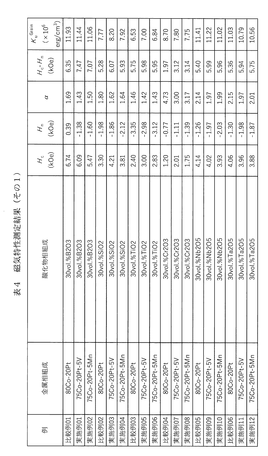
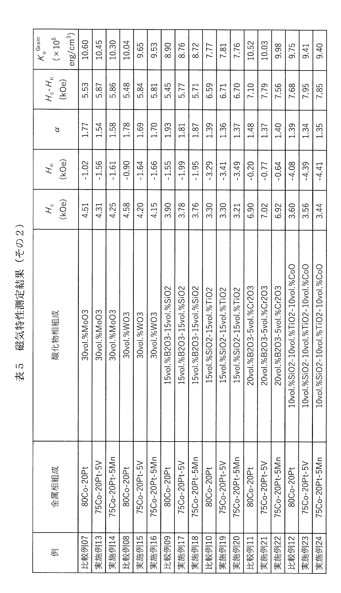
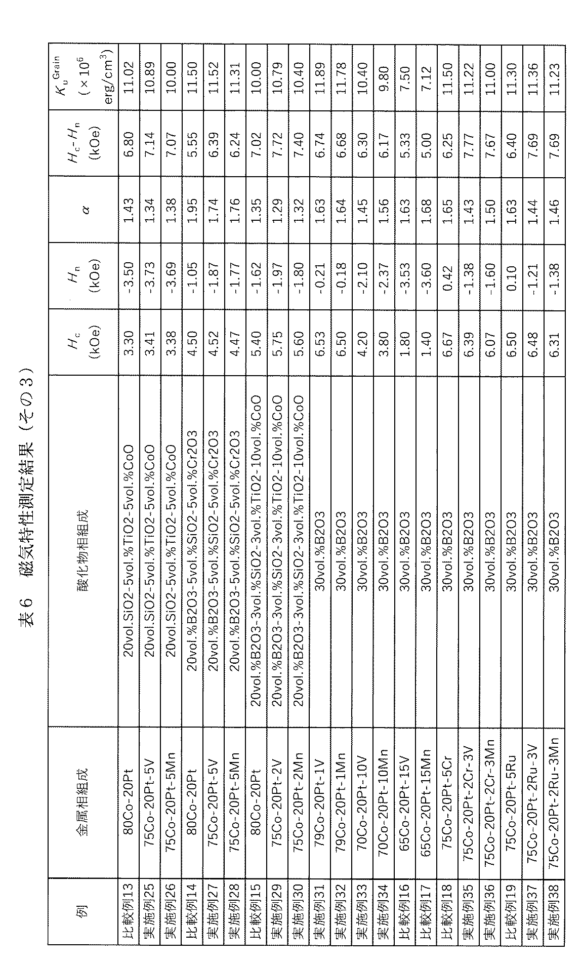
Claims (10)
- Mn及びVから選択される少なくとも1種以上、Pt、残部がCoおよび不可避不純物からなる金属相と、少なくともBとOを含有する酸化物相と、からなる磁気記録媒体用スパッタリングターゲット。
- 前記磁気記録媒体用スパッタリングターゲットの金属相成分の合計に対して、Ptを1mol%以上30mol%以下、Mn及びVから選択される少なくとも1種以上を0.5mol%以上10mol%以下含有し、
前記磁気記録媒体用スパッタリングターゲットの全体に対して前記酸化物相を25vol%以上40vol%以下含有する
ことを特徴とする請求項1に記載の磁気記録媒体用スパッタリングターゲット。 - Mn及びVから選択される少なくとも1種以上、Cr及びRuから選択される少なくとも1種以上、Pt、残部がCoおよび不可避不純物からなる金属相と、少なくともBとOを含有する酸化物相と、からなる磁気記録媒体用スパッタリングターゲット。
- 前記磁気記録媒体用スパッタリングターゲットの金属相成分の合計に対して、Ptを1mol%以上30mol%以下、Mn及びVから選択される少なくとも1種以上を0.5mol%以上10mol%以下、CrもしくはRuから選択される少なくとも1種以上を0.5mol%超過30mol%以下含有し、
前記磁気記録媒体用スパッタリングターゲットの全体に対して前記酸化物相を25vol%以上40vol%以下含有する
ことを特徴とする請求項3に記載の磁気記録媒体用スパッタリングターゲット。 - 前記酸化物相は、V、Ru、Ti、Si、Ta、Cr、Al、Nb、Mn、Co、Ni、Zn、Y、Mo、W、La、Ce、Nd、Sm、Eu、Gd、Yb、Lu、およびZrから選択される少なくとも1の元素の酸化物をさらに含有することを特徴とする請求項1~4のいずれか1項に記載の磁気記録媒体用スパッタリングターゲット。
- Mn及びVから選択される少なくとも1種以上、Pt、残部がCoおよび不可避不純物からなる金属相と、酸化物相と、からなる磁気記録媒体用スパッタリングターゲット。
- 前記磁気記録媒体用スパッタリングターゲットの金属相成分の合計に対して、Ptを1mol%以上30mol%以下、Mn及びVから選択される少なくとも1種以上を0.5mol%以上10mol%以下含有し、
前記磁気記録媒体用スパッタリングターゲットの全体に対して前記酸化物相を25vol%以上40vol%以下含有する
ことを特徴とする請求項6に記載の磁気記録媒体用スパッタリングターゲット。 - Mn及びVから選択される少なくとも1種以上、Cr及びRuから選択される少なくとも1種以上、Pt、残部がCoおよび不可避不純物からなる金属相と、酸化物相と、からなる磁気記録媒体用スパッタリングターゲット。
- 前記磁気記録媒体用スパッタリングターゲットの金属相成分の合計に対して、Ptを1mol%以上30mol%以下、Mn及びVから選択される少なくとも1種以上を0.5mol%以上10mol%以下、CrもしくはRuから選択される少なくとも1種以上を0.5mol%超過30mol%以下含有し、
前記磁気記録媒体用スパッタリングターゲットの全体に対して前記酸化物相を25vol%以上40vol%以下含有する
ことを特徴とする請求項7に記載の磁気記録媒体用スパッタリングターゲット。 - 前記酸化物相は、B、V、Ru、Ti、Si、Ta、Cr、Al、Nb、Mn、Co、Ni、Zn、Y、Mo、W、La、Ce、Nd、Sm、Eu、Gd、Yb、Lu、およびZrから選択される少なくとも1の元素の酸化物をさらに含有することを特徴とする請求項6~9のいずれか1項に記載の磁気記録媒体用スパッタリングターゲット。
Priority Applications (3)
| Application Number | Priority Date | Filing Date | Title |
|---|---|---|---|
| CN202080051547.8A CN114144541B (zh) | 2019-07-18 | 2020-07-16 | 磁记录介质用溅射靶 |
| JP2021533123A JP7462636B2 (ja) | 2019-07-18 | 2020-07-16 | 磁気記録媒体用スパッタリングターゲット |
| US17/628,065 US12230485B2 (en) | 2019-07-18 | 2020-07-16 | Sputtering target for magnetic recording medium |
Applications Claiming Priority (2)
| Application Number | Priority Date | Filing Date | Title |
|---|---|---|---|
| JP2019-132859 | 2019-07-18 | ||
| JP2019132859 | 2019-07-18 |
Publications (1)
| Publication Number | Publication Date |
|---|---|
| WO2021010490A1 true WO2021010490A1 (ja) | 2021-01-21 |
Family
ID=74210926
Family Applications (1)
| Application Number | Title | Priority Date | Filing Date |
|---|---|---|---|
| PCT/JP2020/028611 Ceased WO2021010490A1 (ja) | 2019-07-18 | 2020-07-16 | 磁気記録媒体用スパッタリングターゲット |
Country Status (5)
| Country | Link |
|---|---|
| US (1) | US12230485B2 (ja) |
| JP (1) | JP7462636B2 (ja) |
| CN (1) | CN114144541B (ja) |
| TW (1) | TWI812869B (ja) |
| WO (1) | WO2021010490A1 (ja) |
Cited By (1)
| Publication number | Priority date | Publication date | Assignee | Title |
|---|---|---|---|---|
| WO2025225073A1 (ja) * | 2024-04-25 | 2025-10-30 | Jx金属株式会社 | 磁性材ターゲット及び磁性材ターゲット組立品 |
Families Citing this family (1)
| Publication number | Priority date | Publication date | Assignee | Title |
|---|---|---|---|---|
| WO2023173139A2 (en) * | 2022-03-11 | 2023-09-14 | Georgetown University | Boron-based and high-entropy magnetic materials |
Citations (5)
| Publication number | Priority date | Publication date | Assignee | Title |
|---|---|---|---|---|
| JPS5988807A (ja) * | 1982-11-12 | 1984-05-22 | Nec Corp | 磁気記憶体 |
| JPH11175944A (ja) * | 1997-12-10 | 1999-07-02 | Hitachi Ltd | 磁気記録媒体及び磁気記憶装置 |
| JP2016115379A (ja) * | 2014-12-15 | 2016-06-23 | 昭和電工株式会社 | 垂直記録媒体、垂直記録再生装置 |
| JP2016160530A (ja) * | 2015-03-05 | 2016-09-05 | 光洋應用材料科技股▲分▼有限公司 | 磁気合金スパッタリングターゲット及び磁気記録媒体用記録層 |
| WO2017170138A1 (ja) * | 2016-03-31 | 2017-10-05 | Jx金属株式会社 | 強磁性材スパッタリングターゲット |
Family Cites Families (4)
| Publication number | Priority date | Publication date | Assignee | Title |
|---|---|---|---|---|
| US20060042938A1 (en) * | 2004-09-01 | 2006-03-02 | Heraeus, Inc. | Sputter target material for improved magnetic layer |
| JP5394577B2 (ja) * | 2010-12-22 | 2014-01-22 | Jx日鉱日石金属株式会社 | 強磁性材スパッタリングターゲット |
| MY192454A (en) | 2016-11-01 | 2022-08-21 | Tanaka Precious Metal Ind | Sputtering target for magnetic recording media |
| MY191374A (en) * | 2016-12-28 | 2022-06-21 | Jx Nippon Mining & Metals Corp | Magnetic material sputtering target and method for manufacturing same |
-
2020
- 2020-07-16 US US17/628,065 patent/US12230485B2/en active Active
- 2020-07-16 CN CN202080051547.8A patent/CN114144541B/zh active Active
- 2020-07-16 JP JP2021533123A patent/JP7462636B2/ja active Active
- 2020-07-16 TW TW109124056A patent/TWI812869B/zh active
- 2020-07-16 WO PCT/JP2020/028611 patent/WO2021010490A1/ja not_active Ceased
Patent Citations (5)
| Publication number | Priority date | Publication date | Assignee | Title |
|---|---|---|---|---|
| JPS5988807A (ja) * | 1982-11-12 | 1984-05-22 | Nec Corp | 磁気記憶体 |
| JPH11175944A (ja) * | 1997-12-10 | 1999-07-02 | Hitachi Ltd | 磁気記録媒体及び磁気記憶装置 |
| JP2016115379A (ja) * | 2014-12-15 | 2016-06-23 | 昭和電工株式会社 | 垂直記録媒体、垂直記録再生装置 |
| JP2016160530A (ja) * | 2015-03-05 | 2016-09-05 | 光洋應用材料科技股▲分▼有限公司 | 磁気合金スパッタリングターゲット及び磁気記録媒体用記録層 |
| WO2017170138A1 (ja) * | 2016-03-31 | 2017-10-05 | Jx金属株式会社 | 強磁性材スパッタリングターゲット |
Cited By (2)
| Publication number | Priority date | Publication date | Assignee | Title |
|---|---|---|---|---|
| WO2025225073A1 (ja) * | 2024-04-25 | 2025-10-30 | Jx金属株式会社 | 磁性材ターゲット及び磁性材ターゲット組立品 |
| JP7815548B1 (ja) * | 2024-04-25 | 2026-02-17 | Jx金属株式会社 | 磁性材ターゲット及び磁性材ターゲット組立品 |
Also Published As
| Publication number | Publication date |
|---|---|
| CN114144541A (zh) | 2022-03-04 |
| JP7462636B2 (ja) | 2024-04-05 |
| US12230485B2 (en) | 2025-02-18 |
| US20220262608A1 (en) | 2022-08-18 |
| CN114144541B (zh) | 2024-12-10 |
| TW202120720A (zh) | 2021-06-01 |
| JPWO2021010490A1 (ja) | 2021-01-21 |
| TWI812869B (zh) | 2023-08-21 |
Similar Documents
| Publication | Publication Date | Title |
|---|---|---|
| JPWO2020027235A1 (ja) | 磁気記録媒体用スパッタリングターゲット | |
| US10971181B2 (en) | Sputtering target for magnetic recording media | |
| US10636633B2 (en) | Sputtering target and process for production thereof | |
| WO2021010490A1 (ja) | 磁気記録媒体用スパッタリングターゲット | |
| JP2023144067A (ja) | スパッタリングターゲット、グラニュラ膜および垂直磁気記録媒体 | |
| JP2024040256A (ja) | スパッタリングターゲット、積層膜の製造方法および、磁気記録媒体の製造方法 | |
| CN108291294B (zh) | 溅射靶 | |
| JPWO2014141737A1 (ja) | スパッタリングターゲット | |
| JP7554192B2 (ja) | 非磁性層形成用スパッタリングターゲット部材 | |
| US11939663B2 (en) | Magnetic film and perpendicular magnetic recording medium | |
| WO2020053972A1 (ja) | スパッタリングターゲット、磁性膜および、磁性膜の製造方法 | |
| CN109819662B (zh) | 溅镀靶、积层膜的制造方法、积层膜及磁记录媒体 |
Legal Events
| Date | Code | Title | Description |
|---|---|---|---|
| 121 | Ep: the epo has been informed by wipo that ep was designated in this application |
Ref document number: 20840403 Country of ref document: EP Kind code of ref document: A1 |
|
| ENP | Entry into the national phase |
Ref document number: 2021533123 Country of ref document: JP Kind code of ref document: A |
|
| NENP | Non-entry into the national phase |
Ref country code: DE |
|
| 122 | Ep: pct application non-entry in european phase |
Ref document number: 20840403 Country of ref document: EP Kind code of ref document: A1 |