WO2021010200A1 - 情報処理装置および方法 - Google Patents
情報処理装置および方法 Download PDFInfo
- Publication number
- WO2021010200A1 WO2021010200A1 PCT/JP2020/026322 JP2020026322W WO2021010200A1 WO 2021010200 A1 WO2021010200 A1 WO 2021010200A1 JP 2020026322 W JP2020026322 W JP 2020026322W WO 2021010200 A1 WO2021010200 A1 WO 2021010200A1
- Authority
- WO
- WIPO (PCT)
- Prior art keywords
- order
- information
- decoding
- data
- unit
- Prior art date
Links
Images


Classifications
-
- H—ELECTRICITY
- H04—ELECTRIC COMMUNICATION TECHNIQUE
- H04N—PICTORIAL COMMUNICATION, e.g. TELEVISION
- H04N19/00—Methods or arrangements for coding, decoding, compressing or decompressing digital video signals
- H04N19/42—Methods or arrangements for coding, decoding, compressing or decompressing digital video signals characterised by implementation details or hardware specially adapted for video compression or decompression, e.g. dedicated software implementation
-
- G—PHYSICS
- G06—COMPUTING; CALCULATING OR COUNTING
- G06T—IMAGE DATA PROCESSING OR GENERATION, IN GENERAL
- G06T9/00—Image coding
- G06T9/001—Model-based coding, e.g. wire frame
-
- G—PHYSICS
- G06—COMPUTING; CALCULATING OR COUNTING
- G06T—IMAGE DATA PROCESSING OR GENERATION, IN GENERAL
- G06T9/00—Image coding
- G06T9/40—Tree coding, e.g. quadtree, octree
-
- G—PHYSICS
- G06—COMPUTING; CALCULATING OR COUNTING
- G06T—IMAGE DATA PROCESSING OR GENERATION, IN GENERAL
- G06T17/00—Three dimensional [3D] modelling, e.g. data description of 3D objects
-
- H—ELECTRICITY
- H04—ELECTRIC COMMUNICATION TECHNIQUE
- H04N—PICTORIAL COMMUNICATION, e.g. TELEVISION
- H04N19/00—Methods or arrangements for coding, decoding, compressing or decompressing digital video signals
- H04N19/10—Methods or arrangements for coding, decoding, compressing or decompressing digital video signals using adaptive coding
- H04N19/102—Methods or arrangements for coding, decoding, compressing or decompressing digital video signals using adaptive coding characterised by the element, parameter or selection affected or controlled by the adaptive coding
- H04N19/13—Adaptive entropy coding, e.g. adaptive variable length coding [AVLC] or context adaptive binary arithmetic coding [CABAC]
-
- H—ELECTRICITY
- H04—ELECTRIC COMMUNICATION TECHNIQUE
- H04N—PICTORIAL COMMUNICATION, e.g. TELEVISION
- H04N19/00—Methods or arrangements for coding, decoding, compressing or decompressing digital video signals
- H04N19/10—Methods or arrangements for coding, decoding, compressing or decompressing digital video signals using adaptive coding
- H04N19/169—Methods or arrangements for coding, decoding, compressing or decompressing digital video signals using adaptive coding characterised by the coding unit, i.e. the structural portion or semantic portion of the video signal being the object or the subject of the adaptive coding
- H04N19/184—Methods or arrangements for coding, decoding, compressing or decompressing digital video signals using adaptive coding characterised by the coding unit, i.e. the structural portion or semantic portion of the video signal being the object or the subject of the adaptive coding the unit being bits, e.g. of the compressed video stream
-
- H—ELECTRICITY
- H04—ELECTRIC COMMUNICATION TECHNIQUE
- H04N—PICTORIAL COMMUNICATION, e.g. TELEVISION
- H04N19/00—Methods or arrangements for coding, decoding, compressing or decompressing digital video signals
- H04N19/30—Methods or arrangements for coding, decoding, compressing or decompressing digital video signals using hierarchical techniques, e.g. scalability
-
- H—ELECTRICITY
- H04—ELECTRIC COMMUNICATION TECHNIQUE
- H04N—PICTORIAL COMMUNICATION, e.g. TELEVISION
- H04N19/00—Methods or arrangements for coding, decoding, compressing or decompressing digital video signals
- H04N19/44—Decoders specially adapted therefor, e.g. video decoders which are asymmetric with respect to the encoder
-
- H—ELECTRICITY
- H04—ELECTRIC COMMUNICATION TECHNIQUE
- H04N—PICTORIAL COMMUNICATION, e.g. TELEVISION
- H04N19/00—Methods or arrangements for coding, decoding, compressing or decompressing digital video signals
- H04N19/50—Methods or arrangements for coding, decoding, compressing or decompressing digital video signals using predictive coding
- H04N19/597—Methods or arrangements for coding, decoding, compressing or decompressing digital video signals using predictive coding specially adapted for multi-view video sequence encoding
-
- H—ELECTRICITY
- H04—ELECTRIC COMMUNICATION TECHNIQUE
- H04N—PICTORIAL COMMUNICATION, e.g. TELEVISION
- H04N19/00—Methods or arrangements for coding, decoding, compressing or decompressing digital video signals
- H04N19/90—Methods or arrangements for coding, decoding, compressing or decompressing digital video signals using coding techniques not provided for in groups H04N19/10-H04N19/85, e.g. fractals
- H04N19/96—Tree coding, e.g. quad-tree coding
Definitions
- the present disclosure relates to an information processing device and a method, and more particularly to an information processing device and a method capable of suppressing an increase in the load of decoding processing of coded data of a point cloud.
- the point cloud data is composed of geometry data (also referred to as position information) and attribute data (also referred to as attribute information) of each point. Therefore, the point cloud is encoded for each of its geometry data and attribute data.
- Non-Patent Document 2 Various methods have been proposed as methods for encoding attribute data. For example, it has been proposed to use a technique called Lifting (see, for example, Non-Patent Document 2). In addition, a method has been proposed in which attribute data can be decoded in a scalable manner (see, for example, Non-Patent Document 3). Further, although it is not Lifting, a method capable of referencing the decoded attribute data in LoD has also been considered (see, for example, Non-Patent Document 4).
- the attribute data is encoded by using the positional relationship between the points, assuming that the geometry data including the deterioration due to compression is known. More specifically, the coding of attribute data is performed by utilizing the correlation of points at spatially close distances. In order to utilize such a correlation between points, points in a three-dimensional space are mapped one-dimensionally using a Morton code, and sorting is performed according to the value of the Morton code. That is, each point is arranged in Morton order. This guarantees that adjacent points on the mapped one-dimensional are spatially close.
- this sorting process may increase the load of the point cloud coded data decoding process.
- This disclosure has been made in view of such a situation, and makes it possible to suppress an increase in the load of the decoding process of the coded data of the point cloud.
- the position information of the point cloud that expresses a three-dimensional object as a set of points is obtained, and the decoding result of the coded data of the position information is the processing order of the attribute information of the point cloud.
- the position information of the point cloud that expresses a three-dimensional object as a set of points is obtained, and the decoding result of the coded data of the position information is the processing order of the attribute information of the point cloud.
- the information processing device on the other side of the present technology decodes the coded data of the position information of the point cloud that expresses the object of the three-dimensional shape as a set of points, and outputs the decoding results in the processing order of the attribute information of the point cloud. It is an information processing device including a decoding unit that outputs data.
- the information processing method of another aspect of the present technology decodes the coded data of the position information of the point cloud that expresses the object of the three-dimensional shape as a set of points, and the decoding result is in the processing order of the attribute information of the point cloud. This is an information processing method to output.
- the position information of the point cloud that expresses a three-dimensional object as a set of points is the position information of the point cloud
- the decoding result of the coded data of the position information is the attribute information of the point cloud. It is encoded in the order in which it is output in the processing order, and the encoded data is generated.
- the coded data of the position information of the point cloud representing the object of the three-dimensional shape as a set of points is decoded, and the decoding result is the attribute information of the point cloud. Output in processing order.
- Non-Patent Document 1 (above)
- Non-Patent Document 2 (above)
- Non-Patent Document 3 (above)
- Non-Patent Document 4 (above)
- Non-Patent Document 5 Sebastien Lasserre, David Flynn, "[PCC] Inference of a mode using point location direct coding in TMC3", ISO / IEC JTC1 / SC29 / WG11 MPEG2018 / m42239, January 2018, Gwangju, Korea
- ⁇ Point cloud> Conventionally, a point cloud that represents a three-dimensional structure based on the position information and attribute information of a point cloud, and a mesh that is composed of vertices, edges, and faces and defines a three-dimensional shape using polygonal representation. ) Etc. existed.
- a three-dimensional structure (three-dimensional object) is expressed as a set of a large number of points (point cloud). That is, the point cloud data (also referred to as point cloud data) is composed of geometry data (also referred to as position information) and attribute data (also referred to as attribute information) of each point in this point cloud. Attribute data can contain arbitrary information. For example, color information, reflectance information, normal information, and the like may be included in the attribute data. Therefore, the data structure is relatively simple, and an arbitrary three-dimensional structure can be expressed with sufficient accuracy by using a sufficiently large number of points.
- a voxel is a three-dimensional area for quantizing geometry data (position information).
- the three-dimensional area containing the point cloud is divided into small three-dimensional areas called voxels, and each voxel indicates whether or not the points are included. By doing so, the position of each point is quantized in voxel units. Therefore, by converting the point cloud data into such voxel data (also referred to as voxel data), the increase in the amount of information is suppressed (typically, the amount of information is reduced). Can be done.
- Octree is a tree-structured version of voxel data.
- the value of each bit of the lowest node of this Octree indicates the presence or absence of a point for each voxel. For example, a value "1" indicates a voxel containing points, and a value "0" indicates a voxel containing no points.
- one node corresponds to eight voxels. That is, each node of the Octtree is composed of 8 bits of data, and the 8 bits indicate the presence or absence of points of 8 voxels.
- the upper node of the Octtree indicates the presence or absence of a point in the area where the eight voxels corresponding to the lower node belonging to the node are combined into one. That is, the upper node is generated by collecting the voxel information of the lower node. If a node having a value of "0", that is, all eight corresponding voxels do not contain points, that node is deleted.
- Octree can indicate the presence or absence of voxel points at each resolution.
- the position information can be decoded from the highest resolution (top layer) to a desired layer (resolution), and the point cloud data of that resolution can be restored. That is, it is possible to easily decode at an arbitrary resolution without decoding unnecessary layer (resolution) information. In other words, voxel (resolution) scalability can be achieved.
- the voxel in the region where the point does not exist can be reduced in resolution, so that further increase in the amount of information can be suppressed (typically, the amount of information). Can be reduced).
- attribute data attribute data
- RAHT Restriction Adaptive Hierarchical Transform
- Lifting a transformation called Lifting as described in Non-Patent Document 2
- the attribute data of each point is encoded as a difference value from the predicted value derived by using the attribute data of other points.
- each point is hierarchized, and the difference value is derived according to the hierarchical structure.
- each point is classified into a predicted point and a reference point, and the predicted value of the attribute data of the predicted point is derived using the attribute data of the reference point, and the attribute data of the predicted point and the attribute data of the predicted point.
- the difference value from the predicted value is derived.
- this hierarchical structure is generated independently of the geometric data hierarchical structure (for example, Octree), and basically does not correspond to the geometric data hierarchical structure.
- the method to which Lifting described in Non-Patent Document 2 is applied does not correspond to the scalable decoding of the resolution.
- the layering described in Non-Patent Document 3 corresponds to the scalable decoding of the resolution.
- the attribute data is layered so as to match the hierarchical structure of the Octtree of the geometry data. That is, when a point exists in the area corresponding to the voxel of the geometry data (when the attribute data corresponding to the point exists), the point also exists in the voxel one layer higher than the voxel (corresponding to the point). Select the reference point and the prediction point so that the attribute data to be used exists. That is, the attribute information is hierarchized according to the Octtree hierarchical structure of the geometry data.
- the coding / decoding of the attribute data is performed by utilizing the correlation of points at spatially close distances.
- the points in the three-dimensional space are mapped one-dimensionally by using the Morton code, and the points are sorted by the value of the Morton code. That is, the geometry data is sorted and each point is arranged in Morton order. This guarantees that adjacent points on the mapped one-dimensional are spatially close.
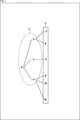
- node b to node d belong to node a
- points F to H belong to node b
- point J belongs to node c
- points K and point L belong to node d.
- Node a, node b, and node d are Octree-encoded
- node c is encoded by applying DCM (Direct Coding Mode).
- node a At that time, processing is started from node a, and then node b, node c, and node d are processed.
- the processing order of the node b, the node c, and the node d is not defined, and the processing can be performed in parallel.
- the node c is encoded by applying DCM, the point J is generally output earlier than the other points.
- points F to H are output as decoding results by processing the node b, but the output order of these is not specified.
- the points K and L are output as the decoding result, but the output order of these is not specified.
- the output order of points F to H is in no particular order
- the output order of points K and L is in no particular order
- the output order of points F to H and points K and L is in no particular order.
- the output order of the geometry data at each point has a certain degree of freedom, so there is a risk that it will not match the processing order of the attribute data. That is, it was not guaranteed that the geometry data of each point was output in the processing order of the attribute data. Therefore, in order to process the attribute data in the above-mentioned processing order, it is necessary to perform the point rearrangement processing using the above-mentioned geometry data.
- this sorting process has a high calculation cost, that is, a large processing load. That is, the processing amount and processing time of this sorting process are not small. Therefore, there is a possibility that the load of the decoding process of the coded data of the point cloud will increase by performing this sorting process. For example, the calculation cost increases due to this sorting process, which may make it difficult to process the decoding of the coded data of the point cloud in real time. Therefore, in order to reliably realize the real-time processing of decoding the coded data of the point cloud, there is a risk that the implementation cost will increase.
- the output order of the decoding results of the geometry data is set to a predetermined order.
- the geometry data is encoded so that the output order of the decoding results of the geometry data is guaranteed to be in a predetermined order.
- the encoded data of the geometry data is decoded so that the decoding results are output in a predetermined order.
- the point sorting process becomes unnecessary, it is possible to suppress an increase in the load of the point cloud coded data decoding process. Therefore, it is possible to suppress an increase in the implementation cost for surely realizing the real-time processing of decoding the coded data of the point cloud.
- the output order is fixed and becomes known. Therefore, since the point reordering process becomes unnecessary, it is possible to suppress an increase in the load of the point cloud coded data decoding process.
- This predetermined order may be any order as long as it is known when decoding the coded data of the geometry data.
- this predetermined order may be the Morton Order.
- this predetermined order may be used as the processing order of the attribute data. That is, the output order of the decoding result of the geometry data may be the same as the processing order of the attribute data.
- the geometry data (position information) of a point cloud that expresses a three-dimensional object as a set of points and the decoding result of the coded data of the geometry data is in the processing order of the attribute data (attribute information) of the point cloud. It may be encoded in the order in which it is output, and the encoded data may be generated.
- the geometry data (position information) of a point cloud that expresses a three-dimensional object as a set of points is obtained, and the decoding result of the coded data of the geometry data is the attribute data (attribute) of the point cloud. It may be provided with a coding unit that encodes in the order of output in the processing order of information) and generates the encoded data.
- the method of encoding the geometry data is arbitrary.
- CABAC Context-based Adaptive Binary Arithmetic Code
- the encoded data are decoded in the same order as the coding order. Therefore, in this case, by encoding the geometry data in the processing order of the attribute data, it is guaranteed that the geometry data of the decoding result is output in the same order as the processing order of the attribute data at the time of decoding. ..
- the encoded data of the position information of the point cloud that expresses a three-dimensional object as a set of points may be decoded, and the decoding result may be output in the processing order of the attribute information of the point cloud.
- a decoding unit that decodes the coded data of the position information of the point cloud that expresses a three-dimensional object as a set of points and outputs the decoding result in the processing order of the attribute information of the point cloud. You may prepare.
- the geometry data of the decoding result is output in the same order as the processing order of the attribute data, so the point sorting process becomes unnecessary. Therefore, it is possible to suppress an increase in the load of the decoding process of the coded data of the point cloud. Therefore, it is possible to suppress an increase in the implementation cost for surely realizing the real-time processing of decoding the coded data of the point cloud.
- the method of decoding the geometry data is arbitrary as long as it corresponds to the coding method.
- the context is used in decoding the encoded data, so the encoded data of the geometry data is arranged in the order (that is, the encoding order of the geometry data). ) May be decoded.
- the output order of the decoding results may be any order.
- the decoding results may be output in Morton order (that is, attribute data may be processed in Morton order). By outputting in the Morton order, it is guaranteed that adjacent points in the output order are spatially close to each other.
- the geometry data may be tree-structured. Further, as shown in "Method 1-3" described in the fourth column from the top of the table shown in FIG. 2, the output order of the decoding results is set to a predetermined order (for example, of the attribute data) at each node of the tree structure. It may be guaranteed that the processing order, Morton order, etc.) are used.
- the tree-structured geometry data may be encoded in the order in which the decoding results are output in the processing order of the point cloud attribute data at each node of the tree structure.
- the coded data of the tree-structured geometry data may be decoded, and the decoding results may be output in the processing order of the point cloud attribute data at each node of the tree structure.
- this tree structure may be anything. For example, it may be Octree. Further, for example, it may be a KD-tree.
- ⁇ DCM> As the coding method of the tree-structured geometry data, not only the method using the tree structure (for example, Octtree coding using Octree) but also the method applying DCM (Direct Coding Mode) should be used. You may.
- this DCM is applied and the processing target node directly or indirectly from the processing target node to the processing target node.
- the relative distance (in each direction of xyz) to each leaf (point) to which it belongs is determined and encoded.
- the "directly belonging node” refers to a node that hangs from the other node in the tree structure.
- a node that directly belongs to the processing target node indicates a node that belongs to the processing target node and is one layer lower than the processing target node (so-called child node).
- the "indirectly belonging node” refers to a node that hangs from the other node via another node in the tree structure.
- a node indirectly belonging to a processing target node indicates a node that belongs to the processing target node via another node and is two or more layers lower than the processing target node (for example, a grandchild node).
- the DCM by applying the DCM, it is possible to omit the coding / decoding of the nodes in the intermediate layer between the processing target node and each leaf directly or indirectly belonging to the processing target node.
- each leaf belonging directly or indirectly to the processing target node can be encoded / decoded. Therefore, it is possible to suppress an increase in the coding / decoding load.
- control information regarding the output order of the decoding result of the point to which the DCM is applied is signaled (encoding side). It may be transmitted from to the decoding side).
- the geometry data at sparse points is encoded by applying DCM, the encoded data of the geometry data is generated, and further, the control information regarding the output order of the decoding result of the encoded data ( (Also referred to as DCM order information) may be generated.
- DCM order information the control information regarding the output order of the decoding result of the encoded data
- the decoding result of the encoded data of the geometry data encoded by applying the DCM may be output in the output order indicated by the DCM order information.
- this DCM order information may be any information as long as it can indicate the output order of the decoding result of the point to which the DCM is applied.
- the DCM order information may include information indicating the output order of the decoding result of the point to which the DCM is applied in order from the beginning.
- the DCM order information indicates the output order of the decoding result of the point to which the DCM is applied, as the difference value from the output order of the decoding result of the point to which the DCM is applied, which is output immediately before. It may be included.
- the DCM order information may include information indicating the output order of the decoding result of the point to which the DCM is applied as a difference value from a predetermined reference order.
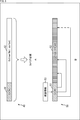
- nodes a to d and points F to L are configured in the same manner as in the case of FIG. Node a belongs to node e. Point M and point L belonging to this node e are encoded / decoded by applying DCM.
- the points F to N surrounded by the solid square 21 are output in the output order as shown by the arrow 22 as described above.
- the output order of the decoding results of the points belonging to the Octree-encoded node is guaranteed as described above. That is, the decoding results of point F, point G, point H, point K, and point L are output in the order of point F ⁇ point G ⁇ point H ⁇ point K ⁇ point L.
- DCM is applied to point M, point J, and point N, they are not always processed in the order shown in FIG. Therefore, the DCM order information is used to output these points in the correct order.
- the DCM order information may indicate the output order of the decoding result in the order from the beginning (for example, the decoding order).
- the DCM order information indicates the output order of the decoding result of the point M as "2", the output order of the decoding result of the point J as "5", and the output order of the decoding result of the point N as "6". Is shown.
- the DCM order information may indicate the output order of the decoding result as a difference value from the output order of the decoding result of the point to which the DCM output immediately before it is applied.
- the DCM order information indicates that the output order of the decoding result of the point M is "2" (the value obtained by subtracting the head “0" from the output order "2" of the decoding result of the point M).
- the DCM order information indicates that the output order of the decoding result of the point J is "3" (the value obtained by subtracting the output order "2" of the decoding result of the point M from the output order "5" of the decoding result of the point J). ..
- the DCM order information indicates that the output order of the decoding result of the point N is "1" (the value obtained by subtracting the output order "5" of the decoding result of the point J from the output order "6" of the decoding result of the point N). ..
- the code amount of the DCM order information can be reduced as compared with the case where the output order of the decoding result is shown in the order from the beginning (for example, the decoding order). That is, it is possible to suppress a decrease in coding efficiency.
- the DCM order information may indicate the output order of the decoding result as a difference value from a predetermined reference order.
- a grid unit that divides each predetermined number of points may be provided, and the difference value may be initialized (for example, set to "0") in the grid unit.
- the alternate long and short dash line 23 indicates one of the grid units. That is, in the case of this example, a grid unit is provided for every five points.
- the DCM order information indicates that the output order of the decoding result of point M is "2" (the value obtained by subtracting the leading "0" from the output order "2" of the decoding result of point M). Further, the DCM order information indicates that the output order of the decoding result of the point J is "3" (the value obtained by subtracting the output order "2” of the decoding result of the point M from the output order "5" of the decoding result of the point J). .. Further, the DCM order information indicates that the output order of the decoding result of the point N is "1” (the value obtained by subtracting the grid unit "5" indicated by the alternate long and short dash line 23 from the output order "6" of the decoding result of the point N). .. In FIG. 3, it is represented as "1'" to indicate that the difference value has been initialized.
- the above DCM order information is generated and transmitted to the decoding side.
- the transmitted DCM order information is acquired, and the output order of the decoding result of the point to which the DCM is applied is controlled based on the DCM order information. That is, the decoding result of the point to which DCM is applied is output in the correct output order.
- the decoding result of the point to which the DCM is applied is inserted at the position of the correct output order in the row of the decoding result of the Octree coded data arranged in the output order.
- the coded data of the tree-structured geometry data as described above can be decoded in a scalable manner. That is, the geometry data can be decoded at a resolution of a layer other than the lowest layer (a layer higher than the lowest layer).
- the position (output order) of the points to which the above-mentioned DCM is applied may change depending on the hierarchy. For example, as shown in FIG. 4, it is assumed that the decoding results of each node (point) in the hierarchy surrounded by the solid line square 31 are output in the order shown by the arrow 32.
- control information even in the intermediate layer of such a tree structure. May be generated. For example, for a point to which DCM is applied, control information (DCM order information) is generated for all layers (or some layers) from the processing target node to which the encoding to which DCM is applied is performed. You may do so.
- control information (DCM order information) may be signaled (transmitted from the coding side to the decoding side). Further, the decoding side may control the output order of the decoding result of the point to which the DCM is applied based on such control information (DCM order information).
- control information may include information on the output order of the decoding result in the middle layer of the tree structure.
- control information may represent the output order of the decoding result as in the case of the lowest layer described above.
- the control information may indicate the output order of the decoding result of the point to which the DCM is applied in the order from the beginning (for example, the decoding order).
- the control information in that case indicates the output order of the decoding result of the point M as "1", the output order of the decoding result of the point J as "3", and the output of the decoding result of the point N.
- the ranking is shown as "4".
- control information indicates the output order of the decoding result of the point to which the DCM is applied by the difference value from the output order of the decoding result of the point to which the DCM is applied, which is output immediately before. You may.
- the control information in that case indicates that the output order of the decoding result of the point M is "1" (the value obtained by subtracting the leading "0" from the output order "1" of the decoding result of the point M).
- the output order of the decoding result of point J is indicated as “2" (the value obtained by subtracting the output order "1" of the decoding result of point M from the output order "3" of the decoding result of point J), and the decoding result of point N is The output rank is shown as “1” (a value obtained by subtracting the output rank "3" of the decoding result of the point J from the output rank "4" of the decoding result of the point N).
- the code amount of the control information can be reduced as compared with the case where the output order of the decoding result is shown in the order from the beginning (for example, the decoding order). That is, it is possible to suppress a decrease in coding efficiency.
- control information of the point to which the DCM is applied may indicate the output order of the decoding result as a difference value from a predetermined reference order.
- a grid unit that divides each predetermined number of points may be provided, and the difference value may be initialized (for example, set to "0") in the grid unit.
- the alternate long and short dash line 33 indicates one of the grid units. That is, in the case of this example, a grid unit is provided for every three points.
- the control information in that case indicates that the output order of the decoding result of the point M is "1" (the value obtained by subtracting the head “0” from the output order "1" of the decoding result of the point M).
- the output order of the decoding result of point J is indicated as “2” (the value obtained by subtracting the output order "1" of the decoding result of point M from the output order "3" of the decoding result of point J), and the decoding result of point N is
- the output rank is shown as "1" (the value obtained by subtracting the grid unit "3" indicated by the alternate long and short dash line 23 from the output rank "4" of the decoding result of the point N). In FIG. 4, it is represented as "1'" to indicate that the difference value has been initialized.
- the code amount of the control information can be reduced as compared with the case where the output order of the decoding result is indicated by the difference value from the point to which the previous DCM is applied. That is, the reduction in coding efficiency can be suppressed.
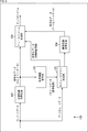
- the coded data 41 of the points encoded by applying DCM and the coded data 42 of the Octree-encoded points are configured as different data from each other and are not arranged in the processing order.
- the Octree-encoded points are not in the order of processing. Therefore, it is necessary to sort the decoding result of the coded data of each point in the processing order of the attribute data (for example, Morton order).
- the bit stream 50 includes the coded data 51 of the points encoded by applying DCM and the Octree code. It has coded data 52 of the converted points and DCM order information 53.
- the DCM order information 53 indicates the output order of the decoding result of each point to which the DCM is applied. Therefore, on the decoding side, the decoding result of each point to which the DCM is applied is inserted into the correct position of the Octree-encoded point group based on the DCM order information 53.
- the control information transmission method as described above is arbitrary. That is, the control information may be transmitted by a predetermined transmission method as in "Method 1-6" described in the seventh row from the top of the table shown in FIG.
- the control information may be included in the coded data of the geometry data.
- the control information may be transmitted as data different from the encoded data of the geometry data.
- the control information may be associated with the coded data of the geometry data by using the identification information or the like.
- the control information may include the identification information of the geometry data of the corresponding data unit (for example, slice).
- FIG. 6 is a block diagram showing an example of a configuration of a coding device, which is an aspect of an information processing device to which the present technology is applied.
- the coding device 100 shown in FIG. 6 is a device that encodes a point cloud (3D data).
- the coding device 100 includes ⁇ 1.
- the point cloud is encoded by applying the above-mentioned technology in Guarantee of output order of decoding results>.
- FIG. 6 shows the main things such as the processing unit and the data flow, and not all of them are shown in FIG. That is, in the coding apparatus 100, there may be a processing unit that is not shown as a block in FIG. 6, or there may be a processing or data flow that is not shown as an arrow or the like in FIG.
- the coding device 100 includes a position information coding unit 101, a position information decoding unit 102, a point cloud generation unit 103, an attribute information coding unit 104, and a bitstream generation unit 105.
- the position information coding unit 101 encodes the geometry data (position information) of the point cloud (3D data) input to the coding device 100. For example, the position information coding unit 101 stratifies the geometry data to generate an Octree, and encodes the Octree. Further, for example, the position information coding unit 101 encodes the geometry data of sparse points by applying DCM.
- the position information coding unit 101 is ⁇ 1.
- the above-mentioned technique is applied in Guarantee of output order of decoding results> to encode geometry data.
- the position information coding unit 101 Octreeizes and encodes the geometry data so that the decoding result of the geometry data is output in the processing order of the attribute data.
- the position information coding unit 101 supplies the coded data of the generated geometry data to the position information decoding unit 102 and the bit stream generation unit 105.
- the position information decoding unit 102 acquires the coded data of the geometry data supplied from the position information coding unit 101, and decodes the coded data.
- This decoding method is arbitrary as long as it corresponds to the coding by the position information coding unit 101. For example, processing such as filtering for denoise and dequantization may be performed.
- the position information decoding unit 102 supplies the generated geometry data (decoding result) to the point cloud generation unit 103.
- the point cloud generation unit 103 acquires the attribute data (attribute information) of the point cloud input to the coding device 100 and the geometry data (decoding result) supplied from the position information decoding unit 102.
- the point cloud generation unit 103 performs a process (recolor process) of matching the attribute data with the geometry data (decoding result).
- the point cloud generation unit 103 supplies the attribute data corresponding to the geometry data (decoding result) to the attribute information coding unit 104.
- the point cloud generation unit 103 has ⁇ 1.
- the above-mentioned technology is applied in Guarantee of output order of decoding results> to generate and encode DCM order information indicating the output order of decoding results at the point where DCM is applied.
- the point cloud generation unit 103 supplies the generated encoded data of the DCM order information to the bitstream generation unit 105.
- the attribute information coding unit 104 acquires the geometry data (decoding result) and the attribute data supplied from the point cloud generation unit 103.
- the attribute information coding unit 104 encodes the attribute data using the geometry data (decoding result) and generates the coded data of the attribute data.
- the attribute information coding unit 104 supplies the coded data of the generated attribute data to the bitstream generation unit 105.
- the bitstream generation unit 105 acquires the coded data of the geometry data supplied from the position information coding unit 101. Further, the bitstream generation unit 105 acquires the coded data of the attribute data supplied from the attribute information coding unit 104. Further, the bitstream generation unit 105 acquires the encoded data of the DCM order information supplied from the point cloud generation unit 103. The bitstream generation unit 105 generates a bitstream including these coded data. The bitstream generation unit 105 outputs the generated bitstream to the outside of the encoding device 100.
- the coding device 100 does not need to perform the point sorting process, so that it is possible to suppress an increase in the load of the point cloud coded data decoding process. Therefore, the coding device 100 can suppress an increase in the mounting cost for surely realizing the real-time processing of decoding the coded data of the point cloud.
- each of these processing units position information coding unit 101 to bitstream generation unit 105) of the coding device 100 has an arbitrary configuration.
- each processing unit may be configured by a logic circuit that realizes the above-mentioned processing.
- each processing unit has, for example, a CPU (Central Processing Unit), a ROM (Read Only Memory), a RAM (Random Access Memory), and the like, and the above-mentioned processing is realized by executing a program using them. You may do so.
- each processing unit may have both configurations, and a part of the above-mentioned processing may be realized by a logic circuit, and the other may be realized by executing a program.
- the configurations of the respective processing units may be independent of each other. For example, some processing units realize a part of the above-mentioned processing by a logic circuit, and some other processing units execute a program.
- the above-mentioned processing may be realized by the other processing unit by both the logic circuit and the execution of the program.
- FIG. 7 is a block diagram showing a main configuration example of the position information coding unit 101 (FIG. 6). Note that FIG. 7 shows the main things such as the processing unit and the data flow, and not all of them are shown in FIG. 7. That is, in the position information coding unit 101, there may be a processing unit that is not shown as a block in FIG. 7, or there may be a processing or data flow that is not shown as an arrow or the like in FIG. 7.
- the position information coding unit 101 includes a bounding box setting unit 111, a voxel setting unit 112, a mode selection unit 113, an Octree coding unit 114, and a DCM coding unit 115.
- the bounding box setting unit 111 performs processing related to the setting of the bounding box. For example, the bounding box setting unit 111 acquires the geometry data of the point cloud data input to the coding device 100. The bounding box setting unit 111 sets the bounding box for the geometry data. The bounding box is information for normalizing the geometry data to be encoded. Voxels are created based on this bounding box. The bounding box setting unit 111 supplies information about the bounding box to the voxel setting unit 112 together with the geometry data.
- the voxel setting unit 112 performs processing related to voxel setting. For example, the voxel setting unit 112 acquires the geometry data supplied from the bounding box setting unit 111 and information on the bounding box. Further, the voxel setting unit 112 sets the voxels by dividing the bounding box set for the geometry data based on the information. That is, the voxel setting unit 112 performs voxelization (quantization of the position of each point) of the geometry data. The voxel setting unit 112 supplies the voxel data, which is the geometry data converted into voxels in this way, to the mode selection unit 113.
- the mode selection unit 113 performs processing related to selection of a coding method (mode). For example, the mode selection unit 113 acquires voxel data supplied from the voxel setting unit 112. Further, the mode selection unit 113 selects a coding method (mode) for each voxel (node in Octree). That is, the mode selection unit 113 selects whether the voxel to be processed is Octree-encoded or encoded by applying DCM (also referred to as DCM encoding).
- DCM also referred to as DCM encoding
- the mode selection unit 113 determines whether or not the voxels to be processed are sparse. When it is determined that the data is not sparse based on a predetermined condition, the mode selection unit 113 selects Octree coding as the coding method, and supplies the voxel data to be processed to the Octree coding unit 114. When it is determined that the data is sparse based on a predetermined condition, the mode selection unit 113 selects DCM coding as the coding method and supplies the voxel data to be processed to the DCM coding unit 115.
- Octree coding unit 114 performs processing related to coding using Octree. For example, the Octree coding unit 114 acquires the voxel data to be processed supplied from the mode selection unit 113. The Octree coding unit 114 uses the voxel data to generate Octree data (ChildMask) of the node to be processed. The Octree coding unit 114 encodes the Octree data of the processing target node by a predetermined method and generates the coded data.
- the Octree coding unit 114 is ⁇ 1. Encoding is performed by applying the above-mentioned technique (for example, "method 1" (which may include methods 1-1 to 1-3) in FIG. 2) described in Guarantee of output order of decoding results>. That is, the Octree coding unit 114 encodes the Octree data of the processing target node so that the decoding result of the geometry data is output in the processing order of the attribute data. For example, the Octree coding unit 114 encodes the Octree data of the processing target node in the order in which the decoding results of the geometry data are output in the Morton order. For example, the Octree encoding unit 114 encodes the decoding results in the order in which the decoding results are output in the processing order of the point cloud attribute data at each node of the Octree.
- “method 1" which may include methods 1-1 to 1-3) in FIG. 2
- Guarantee of output order of decoding results> the Octree coding unit 114 encodes the Octree data of the processing
- the Octree coding unit 114 transfers the coded data (encoded data of the voxel data of the processing target node) generated by performing the coding in this way to the position information decoding unit 102 and the bitstream generation unit 105 (both in FIG. 6). Supply.
- the DCM coding unit 115 performs processing related to coding using DCM. For example, the DCM coding unit 115 acquires the voxel data to be processed supplied from the mode selection unit 113. The DCM coding unit 115 encodes the voxel data by applying DCM to generate coded data. For example, the DCM coding unit 115 uses the voxel data to encode the relative distance from the processing target node to the leaf to generate the coded data. The DCM coding unit 115 supplies the generated coded data to the position information decoding unit 102 and the bitstream generation unit 105 (both of FIG. 6).
- the position information coding unit 101 can perform Octtree coding so that the output order of the decoding results of the geometry data is guaranteed to be a predetermined order. Therefore, since the coding device 100 does not need to perform the point sorting process, it is possible to suppress an increase in the load of the point cloud coded data decoding process.
- each processing unit may be configured by a logic circuit that realizes the above-mentioned processing.
- each processing unit may have, for example, a CPU, ROM, RAM, etc., and execute a program using them to realize the above-mentioned processing.
- each processing unit may have both configurations, and a part of the above-mentioned processing may be realized by a logic circuit, and the other may be realized by executing a program.
- the configurations of the respective processing units may be independent of each other. For example, some processing units realize a part of the above-mentioned processing by a logic circuit, and some other processing units execute a program.
- the above-mentioned processing may be realized by the other processing unit by both the logic circuit and the execution of the program.
- FIG. 8 is a block diagram showing a main configuration example of the point cloud generation unit 103 (FIG. 6). Note that FIG. 8 shows the main things such as the processing unit and the data flow, and not all of them are shown in FIG. That is, in the point cloud generation unit 103, there may be a processing unit that is not shown as a block in FIG. 8, or there may be a processing or data flow that is not shown as an arrow or the like in FIG.
- the point cloud generation unit 103 includes a Morton code conversion unit 121, a sorting unit 122, a DCM order information generation unit 123, a DCM order information coding unit 124, and a recolor processing unit 125.
- the Morton code conversion unit 121 converts the geometry data (decoding result) supplied from the position information decoding unit 102 (FIG. 6) into a Morton code. That is, the Morton code conversion unit 121 maps points in the three-dimensional space to one dimension by using the Morton code. The Morton code conversion unit 121 supplies the geometry data of each point with the Morton code to the sorting unit 122.
- the sorting unit 122 acquires the geometry data supplied from the Morton code conversion unit 121, and sorts the geometry data based on the value of the Morton code. That is, the sorting unit 122 sorts the geometry data of each point in the Morton order. The sorting unit 122 supplies the geometry data of each point sorted in the Morton order to the DCM order information generation unit 123 and the recolor processing unit 125.
- the DCM order information generation unit 123 identifies a point to which DCM is applied at the time of encoding among the geometry data of each point sorted in Morton order, and control information indicating the output order of the decoding result of that point. Generates DCM order information that is.
- the DCM order information may include information indicating the output order of the decoding result of the point to which the DCM is applied in the order from the beginning.
- the DCM order information indicates the output order of the decoding result of the point to which the DCM is applied, as the difference value from the output order of the decoding result of the point to which the DCM is applied, which is output immediately before. It may be included.
- the DCM order information may include information indicating the output order of the decoding result of the point to which the DCM is applied as a difference value from a predetermined reference order.
- the DCM order information generation unit 123 may also generate DCM order information indicating the output order of the point to which the DCM is applied in the middle layer of the Octree. That is, the DCM order information may also include information on the output order of the decoding result in the middle layer of Octree.
- the DCM order information generation unit 123 supplies the generated DCM order information to the DCM order information coding unit 124.
- the DCM order information coding unit 124 performs processing related to encoding the DCM order information. For example, the DCM order information coding unit 124 acquires the DCM order information supplied from the DCM order information generation unit 123. The DCM order information coding unit 124 encodes the acquired DCM order information and generates coded data. This coding method is arbitrary. The DCM order information coding unit 124 supplies the generated encoded data of the DCM order information to the bitstream generation unit 105 (FIG. 6).
- the recolor processing unit 125 performs processing related to processing for matching attribute data with geometry data (recolor processing). For example, the recolor processing unit 125 acquires the attribute data of the point cloud input to the coding device 100. Further, the recolor processing unit 125 acquires the geometry data of each point sorted in the Morton order supplied from the sorting unit 122.
- the recolor processing unit 125 performs a process (recolor processing) to match the acquired attribute data with the acquired geometry data, and generates point cloud data.
- the recolor processing unit 125 supplies the generated point cloud data to the attribute information coding unit 104 (FIG. 6).
- the point cloud generation unit 103 can generate DCM order information and transmit it to the decoding side.
- the decoding result of the points encoded by applying DCM can also be output in an appropriate output order. Therefore, since it is not necessary to rearrange the points at the time of decoding, the coding apparatus 100 can suppress an increase in the mounting cost for surely realizing the real-time processing of decoding the coded data of the point cloud. it can.
- each of these processing units (Morton code conversion unit 121 to recolor processing unit 125) of the point cloud generation unit 103 has an arbitrary configuration.
- each processing unit may be configured by a logic circuit that realizes the above-mentioned processing.
- each processing unit may have, for example, a CPU, ROM, RAM, etc., and execute a program using them to realize the above-mentioned processing.
- each processing unit may have both configurations, and a part of the above-mentioned processing may be realized by a logic circuit, and the other may be realized by executing a program.
- the configurations of the respective processing units may be independent of each other. For example, some processing units realize a part of the above-mentioned processing by a logic circuit, and some other processing units execute a program.
- the above-mentioned processing may be realized by the other processing unit by both the logic circuit and the execution of the program.
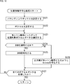
- the coding device 100 encodes the data in the point cloud by executing the coding process. An example of the flow of this coding process will be described with reference to the flowchart of FIG.
- the position information coding unit 101 of the coding device 100 encodes the input point cloud geometry data (position information) in step S101 to generate the coded data of the geometry data. To do. At that time, the position information coding unit 101 is set to ⁇ 1. The processing is performed by applying the above-mentioned technology in Guarantee of output order of decoding results>. The details of the position information coding process will be described later.
- step S102 the position information decoding unit 102 decodes the coded data of the geometry data generated in step S101 and generates the position information.
- step S103 the point cloud generation unit 103 performs recolor processing using the input point cloud attribute data (attribute information) and the geometry data (decoding result) generated in step S102, and obtains the attribute data. Generate point cloud data corresponding to geometry data. At that time, the point cloud generation unit 103 has ⁇ 1. Applying the above-mentioned technology in Guarantee of output order of decoding results>, DCM order information indicating the output order of decoding results at the point to which DCM is applied is generated and encoded. The details of the point cloud generation process will be described later.
- step S104 the attribute information coding unit 104 encodes the attribute data recolored in step S103 by executing the attribute information coding process, and generates the coded data of the attribute data.
- the bit stream generation unit 105 includes the coded data of the geometry data generated in step S101, the coded data of the DCM order information generated in step S103, and the code of the attribute data generated in step S104. Generates and outputs a bit stream containing the converted data.
- step S105 When the process of step S105 is completed, the coding process is completed.
- the coding apparatus 100 can eliminate the need for the point sorting processing at the time of decoding, so that the load of the point cloud coding data decoding processing increases. It can be suppressed. Therefore, the coding device 100 can suppress an increase in the mounting cost for surely realizing the real-time processing of decoding the coded data of the point cloud.
- the bounding box setting unit 111 sets the bounding box for the geometry data to be processed in step S121.
- step S122 the voxel setting unit 112 sets the voxel based on the bounding box set in step S121, and quantizes the geometry data of each point.
- step S123 the mode selection unit 113 selects voxel data to be processed from the voxels set in step S122 according to the Morton order.
- step S124 the mode selection unit 113 determines whether or not to apply DCM to the voxel data to be processed. If it is determined to be sparse based on a predetermined condition, the process proceeds to step S125.
- step S125 the DCM coding unit 115 DCM-encodes the voxel data to be processed.
- the process of step S125 proceeds to step S127.
- step S124 If it is determined in step S124 that the DCM is not applied to the voxel data to be processed, the process proceeds to step S126.
- step S126 the Octree coding unit 114 has ⁇ 1.
- the above-mentioned technology is applied in Guarantee of output order of decoding result>, and Octtree coding is performed on the voxel data to be processed so that the output order of the decoding result is Morton order.
- step S126 the process proceeds to step S127.
- step S127 the mode selection unit 113 determines whether or not all the voxel data has been processed. If there is unprocessed voxel data, the process returns to step S123, and the subsequent processes are repeated. That is, each process of step S123 to step S127 is executed for each voxel data.
- step S127 when it is determined that all the voxel data has been processed, the position information coding process is completed, and the process returns to FIG.
- the coding apparatus 100 can eliminate the need for the point sorting processing at the time of decoding, so that the load of the point cloud coding data decoding processing increases. It can be suppressed. Therefore, the coding device 100 can suppress an increase in the mounting cost for surely realizing the real-time processing of decoding the coded data of the point cloud.
- the Morton code conversion unit 121 (FIG. 8) of the point cloud generation unit 103 converts the geometry data into the Morton code in step S141.
- step S142 the sorting unit 122 sorts the geometry data in Morton order based on the Morton code assigned in step S121.
- step S143 the DCM order information generation unit 123 identifies the points to which the DCM is applied at the time of coding among the geometry data for each point sorted in the Morton order, and outputs the decoding results of the points. Generates DCM order information indicating. At that time, the DCM order information generation unit 123 has ⁇ 1.
- the above-mentioned technology is applied in Guarantee of output order of decoding results> to generate DCM order information.
- step S144 the DCM order information coding unit 124 encodes the DCM order information generated in step S143 and generates encoded data.
- step S145 the recolor processing unit 125 performs a process (recolor processing) to match the acquired attribute data with the acquired geometry data, and generates point cloud data.
- step S145 When the process of step S145 is completed, the point cloud generation process is completed, and the process returns to FIG.
- the coding apparatus 100 can eliminate the need for the point sorting processing at the time of decoding, so that the load of the point cloud coding data decoding processing increases. It can be suppressed. Therefore, the coding device 100 can suppress an increase in the mounting cost for surely realizing the real-time processing of decoding the coded data of the point cloud.
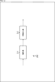
- FIG. 12 is a block diagram showing an example of a configuration of a decoding device, which is an aspect of an information processing device to which the present technology is applied.
- the decoding device 200 shown in FIG. 12 is a device that decodes the coded data of the point cloud (3D data).
- the decoding device 200 has ⁇ 1. Guarantee of output order of decoding results> The above-mentioned technology is applied to decode the coded data of the point cloud.
- FIG. 12 shows the main things such as the processing unit and the data flow, and not all of them are shown in FIG. That is, in the decoding device 200, there may be a processing unit that is not shown as a block in FIG. 12, or there may be a processing or data flow that is not shown as an arrow or the like in FIG.
- the decoding device 200 includes a coded data extraction unit 201, a position information decoding unit 202, an attribute information decoding unit 203, and a point cloud generation unit 204.
- the coded data extraction unit 201 acquires and holds a bit stream input to the decoding device 200.
- the coded data extraction unit 201 extracts coded data of geometry data (position information) and attribute data (attribute information) from the bit stream. At that time, the coded data extraction unit 201 can extract the coded data of all layers from the bit stream. Further, for example, the coded data from the highest layer to the layer specified by the user, the application, or the like (that is, the coded data of a part of the layers) can be extracted from the bit stream.
- the coded data extraction unit 201 supplies the coded data of the extracted geometry data to the position information decoding unit 202.
- the coded data extraction unit 201 supplies the coded data of the extracted attribute data to the attribute information decoding unit 203.
- the position information decoding unit 202 acquires the coded data of the geometry data supplied from the coded data extraction unit 201.
- the position information decoding unit 202 decodes the coded data of the geometry data and generates the geometry data (decoding result). At that time, the position information decoding unit 202 has ⁇ 1.
- Geometry data is decoded by applying the above-mentioned technique in Guarantee of output order of decoding results>. That is, the position information decoding unit 202 decodes the coded data of the geometry data and outputs the decoding result in the processing order of the attribute data of the point cloud.
- the position information decoding unit 202 supplies the generated geometry data (decoding result) to the attribute information decoding unit 203 and the point cloud generation unit 204.
- the attribute information decoding unit 203 acquires the coded data of the attribute data supplied from the coded data extraction unit 201.
- the attribute information decoding unit 203 acquires the geometry data (decoding result) supplied from the position information decoding unit 202.
- the attribute information decoding unit 203 decodes the coded data of the attribute data using the geometry data, and generates the attribute data (decoding result).
- the attribute information decoding unit 203 supplies the generated attribute data (decoding result) to the point cloud generation unit 204.
- the point cloud generation unit 204 acquires the geometry data (decoding result) supplied from the position information decoding unit 202.
- the point cloud generation unit 204 acquires the attribute data (decoding result) supplied from the attribute information decoding unit 203.
- the point cloud generation unit 204 generates a point cloud (decoding result) using the geometry data (decoding result) and attribute data (decoding result).
- the point cloud generation unit 204 outputs the generated point cloud (decoding result) data to the outside of the decoding device 200.
- the decoding device 200 can suppress an increase in the load of the decoding process of the coded data of the point cloud. Therefore, it is possible to suppress an increase in the implementation cost for surely realizing the real-time processing of decoding the coded data of the point cloud.
- each processing unit may be configured by a logic circuit that realizes the above-mentioned processing.
- each processing unit may have, for example, a CPU, ROM, RAM, etc., and execute a program using them to realize the above-mentioned processing.
- each processing unit may have both configurations, and a part of the above-mentioned processing may be realized by a logic circuit, and the other may be realized by executing a program.
- the configurations of the respective processing units may be independent of each other. For example, some processing units realize a part of the above-mentioned processing by a logic circuit, and some other processing units execute a program.
- the above-mentioned processing may be realized by the other processing unit by both the logic circuit and the execution of the program.
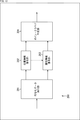
- FIG. 13 is a block diagram showing a main configuration example of the position information decoding unit 202 (FIG. 12). Note that FIG. 13 shows the main things such as the processing unit and the data flow, and not all of them are shown in FIG. That is, in the position information decoding unit 202, there may be a processing unit that is not shown as a block in FIG. 13, or there may be a processing or data flow that is not shown as an arrow or the like in FIG.
- the position information decoding unit 202 has a decoding unit 211 and a DCM insertion unit 212.
- the decoding unit 211 performs processing related to decoding geometry data. For example, the position information decoding unit 202 acquires the coded data of the geometry data supplied from the coded data extraction unit 201. The decoding unit 211 decodes the acquired encoded data and generates (restores) geometry data.
- the decoding unit 211 decodes the coded data of the DCM order information included in the coded data of the geometry data. Further, for example, the decoding unit 211 decodes the encoded data of the Octree data in the Morton order. Further, for example, the decoding unit 211 decodes the DCM-encoded coded data.
- the decoding unit 211 supplies the geometry data generated by decoding (which may include DCM order information, Octree data, geometry data of points to which DCM is applied (also referred to as DCM data), etc.) to the DCM insertion unit 212.
- the DCM insertion unit 212 performs processing related to controlling the output order of the geometry data at the point to which the DCM is applied. For example, the DCM insertion unit 212 acquires geometry data (which may include DCM order information, Octree data, DCM data, etc.) supplied from the decoding unit 211.
- geometry data which may include DCM order information, Octree data, DCM data, etc.
- the DCM insertion unit 212 inserts the acquired DCM data at the position of the output order indicated by the DCM order information in the column of Octtree data sorted in Morton order. That is, the DCM insertion unit 212 controls so that the DCM data is output in the output order indicated by the DCM order information corresponding to the DCM data.
- the DCM insertion unit 212 supplies the Octtree data (geometry data sorted in Morton order) into which the DCM data is inserted to the point cloud generation unit 204 (FIG. 12).
- the decoding device 200 can suppress an increase in the load of the decoding process of the coded data of the point cloud. Therefore, it is possible to suppress an increase in the implementation cost for surely realizing the real-time processing of decoding the coded data of the point cloud.
- each processing unit may be configured by a logic circuit that realizes the above-mentioned processing.
- each processing unit may have, for example, a CPU, ROM, RAM, etc., and execute a program using them to realize the above-mentioned processing.
- each processing unit may have both configurations, and a part of the above-mentioned processing may be realized by a logic circuit, and the other may be realized by executing a program.
- the configurations of the respective processing units may be independent of each other. For example, some processing units realize a part of the above-mentioned processing by a logic circuit, and some other processing units execute a program.
- the above-mentioned processing may be realized by the other processing unit by both the logic circuit and the execution of the program.
- the decoding device 200 decodes the coded data of the point cloud by executing the decoding process.
- An example of the flow of the decoding process will be described with reference to the flowchart of FIG.
- the coded data extraction unit 201 of the decoding device 200 acquires and holds the bit stream in step S201, and the geometry data (position information) and attribute data (position information) of the layer to be decoded from the bit stream. Attribute information) coded data is extracted.
- step S202 the position information decoding unit 202 decodes the coded data of the geometry data extracted in step S201 and generates the geometry data (decoding result). At that time, the position information decoding unit 202 has ⁇ 1.
- the processing is performed by applying the above-mentioned technology in Guarantee of output order of decoding results>. The details of the position information decoding process will be described later.
- step S203 the attribute information decoding unit 203 decodes the coded data of the attribute data extracted in step S201 and generates the attribute data (decoding result).
- step S204 the point cloud generation unit 204 generates point cloud data (decoding result) using the geometry data (decoding result) generated in step S202 and the attribute data (decoding result) generated in step S203. And output.
- step S204 When the process of step S204 is completed, the decryption process is completed.
- the decoding device 200 can suppress an increase in the load of the decoding process of the coded data of the point cloud. Therefore, it is possible to suppress an increase in the implementation cost for surely realizing the real-time processing of decoding the coded data of the point cloud.
- the decoding unit 211 of the position information decoding unit 202 decodes the DCM order information in step S221.
- step S222 the decoding unit 211 decodes the encoded data of the Octree data in the Morton order.
- step S223 the decoding unit 211 decodes the encoded data of the DCM data.
- step S224 the DCM insertion unit 212 transfers the DCM data decoded in step S223 to the output order indicated by the DCM order information decoded in step S221 of the Octree data in Morton order decoded in step S222. Insert it in the corresponding position. That is, the DCM insertion unit 212 controls the output order of the geometry data (decoding result) so that the DCM data is output in the output order indicated by the DCM order information. At that time, the DCM insertion portion 212 is ⁇ 1.
- the processing is performed by applying the above-mentioned technology in Guarantee of output order of decoding results>.
- step S224 When the process of step S224 is completed, the position information decoding process is completed, and the process returns to FIG.
- the decoding device 200 can suppress an increase in the load of the decoding process of the coded data of the point cloud. Therefore, it is possible to suppress an increase in the implementation cost for surely realizing the real-time processing of decoding the coded data of the point cloud.
- the output order of the decoding result of the geometry data may be an order other than the processing order of the attribute data.
- Geometry data included in the subregion 302 can be specified as a group of data. That is, only the geometry data in the partial area 302 can be easily decoded only by designating the first point (Start number) and the last point (End number) as the decoding target.
- control information other than the above-mentioned example may be signaled.
- control information for example, enabled_flag
- a control for designating a range for example, an upper limit or a lower limit of a block size, or both, a slice, a picture, a sequence, a component, a view, a layer, etc.
- Information may be transmitted.
- the series of processes described above can be executed by hardware or by software.
- the programs constituting the software are installed on the computer.
- the computer includes a computer embedded in dedicated hardware, a general-purpose personal computer capable of executing various functions by installing various programs, and the like.
- FIG. 17 is a block diagram showing a configuration example of computer hardware that executes the above-mentioned series of processes programmatically.
- the CPU Central Processing Unit
- ROM Read Only Memory
- RAM Random Access Memory
- the input / output interface 910 is also connected to the bus 904.
- An input unit 911, an output unit 912, a storage unit 913, a communication unit 914, and a drive 915 are connected to the input / output interface 910.
- the input unit 911 includes, for example, a keyboard, a mouse, a microphone, a touch panel, an input terminal, and the like.
- the output unit 912 includes, for example, a display, a speaker, an output terminal, and the like.
- the storage unit 913 includes, for example, a hard disk, a RAM disk, a non-volatile memory, or the like.
- the communication unit 914 includes, for example, a network interface.
- the drive 915 drives a removable medium 921 such as a magnetic disk, an optical disk, a magneto-optical disk, or a semiconductor memory.
- the CPU 901 loads the program stored in the storage unit 913 into the RAM 903 via the input / output interface 910 and the bus 904 and executes the above-described series. Is processed.
- the RAM 903 also appropriately stores data and the like necessary for the CPU 901 to execute various processes.
- the program executed by the computer can be recorded and applied to the removable media 921 as a package media or the like, for example.
- the program can be installed in the storage unit 913 via the input / output interface 910 by mounting the removable media 921 in the drive 915.
- This program can also be provided via wired or wireless transmission media such as local area networks, the Internet, and digital satellite broadcasting. In that case, the program can be received by the communication unit 914 and installed in the storage unit 913.
- this program can be installed in advance in ROM 902 or storage unit 913.
- the coding device 100 and the decoding device 200 have been described as application examples of the present technology, but the present technology can be applied to any configuration.
- this technology is a transmitter or receiver (for example, a television receiver or mobile phone) for satellite broadcasting, cable broadcasting such as cable TV, distribution on the Internet, and distribution to terminals by cellular communication, or It can be applied to various electronic devices such as devices (for example, hard disk recorders and cameras) that record images on media such as optical disks, magnetic disks, and flash memories, and reproduce images from these storage media.
- devices for example, hard disk recorders and cameras
- a processor as a system LSI (Large Scale Integration) or the like (for example, a video processor), a module using a plurality of processors (for example, a video module), a unit using a plurality of modules (for example, a video unit)
- a processor as a system LSI (Large Scale Integration) or the like (for example, a video processor), a module using a plurality of processors (for example, a video module), a unit using a plurality of modules (for example, a video unit)
- a processor as a system LSI (Large Scale Integration) or the like (for example, a video processor), a module using a plurality of processors (for example, a video module), a unit using a plurality of modules (for example, a video unit)
- a set for example, a video set
- this technology can be applied to a network system composed of a plurality of devices.
- the present technology may be implemented as cloud computing that is shared and jointly processed by a plurality of devices via a network.
- this technology is implemented in a cloud service that provides services related to images (moving images) to arbitrary terminals such as computers, AV (AudioVisual) devices, portable information processing terminals, and IoT (Internet of Things) devices. You may try to do it.
- the system means a set of a plurality of components (devices, modules (parts), etc.), and it does not matter whether all the components are in the same housing. Therefore, a plurality of devices housed in separate housings and connected via a network, and a device in which a plurality of modules are housed in one housing are both systems. ..
- Systems, devices, processing units, etc. to which this technology is applied can be used in any field such as transportation, medical care, crime prevention, agriculture, livestock industry, mining, beauty, factories, home appliances, weather, nature monitoring, etc. .. The use is also arbitrary.
- the "flag” is information for identifying a plurality of states, and is not only information used for identifying two states of true (1) or false (0), but also three or more states. It also contains information that can identify the state. Therefore, the value that this "flag” can take may be, for example, 2 values of 1/0 or 3 or more values. That is, the number of bits constituting this "flag” is arbitrary, and may be 1 bit or a plurality of bits.
- the identification information (including the flag) is assumed to include not only the identification information in the bit stream but also the difference information of the identification information with respect to a certain reference information in the bit stream. In, the "flag” and “identification information” include not only the information but also the difference information with respect to the reference information.
- various information (metadata, etc.) regarding the coded data may be transmitted or recorded in any form as long as it is associated with the coded data.
- the term "associate" means, for example, to make the other data available (linkable) when processing one data. That is, the data associated with each other may be combined as one data or may be individual data.
- the information associated with the coded data (image) may be transmitted on a transmission path different from the coded data (image).
- the information associated with the coded data (image) may be recorded on a recording medium (or another recording area of the same recording medium) different from the coded data (image). Good.
- this "association" may be a part of the data, not the entire data. For example, an image and information corresponding to the image may be associated with each other in an arbitrary unit such as a plurality of frames, one frame, or a part within the frame.
- the embodiment of the present technology is not limited to the above-described embodiment, and various changes can be made without departing from the gist of the present technology.
- the configuration described as one device (or processing unit) may be divided and configured as a plurality of devices (or processing units).
- the configurations described above as a plurality of devices (or processing units) may be collectively configured as one device (or processing unit).
- a configuration other than the above may be added to the configuration of each device (or each processing unit).
- a part of the configuration of one device (or processing unit) may be included in the configuration of another device (or other processing unit). ..
- the above-mentioned program may be executed in any device.
- the device may have necessary functions (functional blocks, etc.) so that necessary information can be obtained.
- each step of one flowchart may be executed by one device, or may be shared and executed by a plurality of devices.
- the plurality of processes may be executed by one device, or may be shared and executed by a plurality of devices.
- a plurality of processes included in one step can be executed as processes of a plurality of steps.
- the processes described as a plurality of steps can be collectively executed as one step.
- the processing of the steps for writing the program may be executed in chronological order in the order described in the present specification, and may be executed in parallel or in calls. It may be executed individually at the required timing such as when it is broken. That is, as long as there is no contradiction, the processing of each step may be executed in an order different from the above-mentioned order. Further, the processing of the step for writing this program may be executed in parallel with the processing of another program, or may be executed in combination with the processing of another program.
- a plurality of technologies related to this technology can be independently implemented independently as long as there is no contradiction.
- any plurality of the present technologies can be used in combination.
- some or all of the techniques described in any of the embodiments may be combined with some or all of the techniques described in other embodiments. It is also possible to carry out a part or all of any of the above-mentioned techniques in combination with other techniques not described above.
- the present technology can also have the following configurations.
- the position information of the point cloud which expresses a three-dimensional object as a set of points, is coded in such an order that the decoding result of the coded data of the position information is output in the processing order of the attribute information of the point cloud.
- An information processing device including a coding unit for converting and generating the coded data.
- the coding unit encodes the position information in an order in which the decoding results are output in the Morton order to generate the coded data.
- the coding unit encodes the tree-structured position information in an order in which the decoding results are output in the processing order of the point cloud attribute information at each node of the tree structure.
- the information processing apparatus according to (1) or (2), which generates coded data.
- the information processing apparatus which generates coded data.
- the information processing apparatus (4) The information processing apparatus according to (3), wherein the tree structure is an Octree.
- a DCM coding unit that encodes the position information of the sparse points of the Octree by applying DCM (Direct Coding Mode) to generate the coded data of the position information.
- the information processing apparatus according to (4), further comprising a generation unit that generates control information regarding an output order of a decoding result of the coded data generated by the DCM coding unit.
- the control information includes information indicating the output order of the decoding results in order from the beginning.
- the control information is a difference value from the output order of the decoding result of the coded data of the position information encoded by applying the DCM which is output immediately before the output order of the decoding result.
- the information processing apparatus according to (5) which includes the information indicated by.
- the control information includes information indicating the output order of the decoding result as a difference value from a predetermined reference order.
- the information processing apparatus according to any one of (5) to (8), wherein the control information also includes information regarding an output order of the decoding result in the intermediate layer of the tree structure.
- the position information of the point cloud which expresses a three-dimensional object as a set of points, is coded in such an order that the decoding result of the coded data of the position information is output in the processing order of the attribute information of the point cloud.
- An information processing device including a decoding unit that decodes the coded data of the position information of the point cloud that expresses a three-dimensional object as a set of points and outputs the decoding result in the processing order of the attribute information of the point cloud. .. (12) The information processing apparatus according to (11), wherein the decoding unit outputs the decoding results in Morton order. (13) The decoding unit decodes the coded data of the position information having a tree structure, and outputs the decoding result at each node of the tree structure in the processing order of the attribute information of the point cloud (11). Or the information processing apparatus according to (12). (14) The information processing apparatus according to (13), wherein the tree structure is an Octree.
- the decoding result of the coded data of the position information encoded by applying DCM is output in the output order indicated by the control information regarding the output order of the decoding result of the coded data.
- the control information includes information indicating the output order of the decoding results in order from the beginning.
- the control information is a difference value from the output order of the decoding result of the coded data of the position information encoded by applying the DCM which is output immediately before the output order of the decoding result.
- control information includes information indicating the output order of the decoding result as a difference value from a predetermined reference order.
- the control information also includes information regarding an output order of the decoding result in the intermediate layer of the tree structure.
- 100 coding device 101 position information coding unit, 102 position information decoding unit, 103 point cloud generation unit, 104 attribute information coding unit, 105 bit stream generation unit, 111 bounding box setting unit, 112 boxel setting unit, 113 mode Selection unit, 114 October coding unit, 115 DCM coding unit, 121 Morton code conversion unit, 122 sorting unit, 123 DCM order information generation unit, 124 DCM order information coding unit, 125 recolor processing unit, 200 decoding device, 201 encoded data extraction unit, 202 position information decoding unit, 203 attribute information decoding unit, 204 point cloud generation unit, 211 decoding unit, 212 DCM insertion unit
Landscapes
- Engineering & Computer Science (AREA)
- Multimedia (AREA)
- Physics & Mathematics (AREA)
- General Physics & Mathematics (AREA)
- Theoretical Computer Science (AREA)
- Signal Processing (AREA)
- Computer Graphics (AREA)
- Geometry (AREA)
- Software Systems (AREA)
- Compression Or Coding Systems Of Tv Signals (AREA)
- Compression, Expansion, Code Conversion, And Decoders (AREA)
Abstract
本開示は、ポイントクラウドの符号化データの復号処理の負荷の増大を抑制することができるようにする情報処理装置および方法に関する。 3次元形状のオブジェクトをポイントの集合として表現するポイントクラウドの位置情報を、その位置情報の符号化データの復号結果がそのポイントクラウドの属性情報の処理順で出力されるような順に符号化し、その符号化データを生成する。また、3次元形状のオブジェクトをポイントの集合として表現するポイントクラウドの位置情報の符号化データを復号し、その復号結果をポイントクラウドの属性情報の処理順で出力する。本開示は、例えば、情報処理装置、画像処理装置、符号化装置、復号装置、電子機器、情報処理方法、またはプログラム等に適用することができる。
Description
本開示は、情報処理装置および方法に関し、特に、ポイントクラウドの符号化データの復号処理の負荷の増大を抑制することができるようにした情報処理装置および方法に関する。
従来、例えばポイントクラウド(Point cloud)のような3次元構造を表す3Dデータの符号化方法が考えられた(例えば非特許文献1参照)。ポイントクラウドのデータは、各ポイントのジオメトリデータ(位置情報とも称する)およびアトリビュートデータ(属性情報とも称する)により構成される。したがってポイントクラウドの符号化は、そのジオメトリデータとアトリビュートデータとのそれぞれについて行われる。
アトリビュートデータの符号化方法として様々な方法が提案されている。例えば、Liftingという技術を用いて行うことが提案された(例えば非特許文献2参照)。また、アトリビュートデータをスケーラブルに復号することができるようにする方法も提案された(例えば、非特許文献3参照)。また、Liftingではないが、LoD内において復号済みのアトリビュートデータを参照することができる方法も考えられた(例えば、非特許文献4参照)。
いずれの場合も、アトリビュートデータの符号化は、圧縮による劣化を含めジオメトリデータを既知であるものとして、ポイント間の位置関係を利用して行われる。より具体的には、アトリビュートデータの符号化は、空間的に近い距離にあるポイントの相関を利用して行われる。このようなポイント間の相関を利用するために、モートンコード(Morton code)を利用して3次元空間上のポイントが1次元にマッピングされ、そのモートンコードの値によってソートがかけられる。つまり、各ポイントがモートン順序に整列される。これにより、マッピングした1次元上で隣り合う点が空間的に近傍であることが保証される。
R. Mekuria, Student Member IEEE, K. Blom, P. Cesar., Member, IEEE, "Design, Implementation and Evaluation of a Point Cloud Codec for Tele-Immersive Video",tcsvt_paper_submitted_february.pdf
Khaled Mammou, Alexis Tourapis, Jungsun Kim, Fabrice Robinet, Valery Valentin, Yeping Su, "Lifting Scheme for Lossy Attribute Encoding in TMC1", ISO/IEC JTC1/SC29/WG11 MPEG2018/m42640, April 2018, San Diego, US
Ohji Nakagami, Satoru Kuma, "[G-PCC] Spatial scalability support for G-PCC", ISO/IEC JTC1/SC29/WG11 MPEG2019/m47352, March 2019, Geneva, CH
Toshiyasu Sugio, "[G-PCC] Reference structure modification on attribute predicting transform in TMC13", ISO/IEC JTC1/SC29/WG11 MPEG2018/ m46107, January 2019, Marrakech, MA
しかしながら、この並べ替え処理により、ポイントクラウドの符号化データの復号処理の負荷が増大するおそれがあった。
本開示は、このような状況に鑑みてなされたものであり、ポイントクラウドの符号化データの復号処理の負荷の増大を抑制することができるようにするものである。
本技術の一側面の情報処理装置は、3次元形状のオブジェクトをポイントの集合として表現するポイントクラウドの位置情報を、前記位置情報の符号化データの復号結果が前記ポイントクラウドの属性情報の処理順で出力されるような順に符号化し、前記符号化データを生成する符号化部とを備える情報処理装置である。
本技術の一側面の情報処理方法は、3次元形状のオブジェクトをポイントの集合として表現するポイントクラウドの位置情報を、前記位置情報の符号化データの復号結果が前記ポイントクラウドの属性情報の処理順で出力されるような順に符号化し、前記符号化データを生成する情報処理方法である。
本技術の他の側面の情報処理装置は、3次元形状のオブジェクトをポイントの集合として表現するポイントクラウドの位置情報の符号化データを復号し、復号結果を前記ポイントクラウドの属性情報の処理順で出力する復号部を備える情報処理装置である。
本技術の他の側面の情報処理方法は、3次元形状のオブジェクトをポイントの集合として表現するポイントクラウドの位置情報の符号化データを復号し、復号結果を前記ポイントクラウドの属性情報の処理順で出力する情報処理方法である。
本技術の一側面の情報処理装置および方法においては、3次元形状のオブジェクトをポイントの集合として表現するポイントクラウドの位置情報が、その位置情報の符号化データの復号結果がポイントクラウドの属性情報の処理順で出力されるような順に符号化され、その符号化データが生成される。
本技術の他の側面の情報処理装置および方法においては、3次元形状のオブジェクトをポイントの集合として表現するポイントクラウドの位置情報の符号化データが復号され、その復号結果がポイントクラウドの属性情報の処理順で出力される。
以下、本開示を実施するための形態(以下実施の形態とする)について説明する。なお、説明は以下の順序で行う。
1.復号結果の出力順の保証
2.第1の実施の形態(符号化装置)
3.第2の実施の形態(復号装置)
4.付記
1.復号結果の出力順の保証
2.第1の実施の形態(符号化装置)
3.第2の実施の形態(復号装置)
4.付記
<1.復号結果の出力順の保証>
<技術内容・技術用語をサポートする文献等>
本技術で開示される範囲は、実施の形態に記載されている内容だけではなく、出願当時において公知となっている以下の非特許文献に記載されている内容も含まれる。
<技術内容・技術用語をサポートする文献等>
本技術で開示される範囲は、実施の形態に記載されている内容だけではなく、出願当時において公知となっている以下の非特許文献に記載されている内容も含まれる。
非特許文献1:(上述)
非特許文献2:(上述)
非特許文献3:(上述)
非特許文献4:(上述)
非特許文献5:Sebastien Lasserre, David Flynn, "[PCC] Inference of a mode using point location direct coding in TMC3", ISO/IEC JTC1/SC29/WG11 MPEG2018/m42239, January 2018, Gwangju, Korea
非特許文献2:(上述)
非特許文献3:(上述)
非特許文献4:(上述)
非特許文献5:Sebastien Lasserre, David Flynn, "[PCC] Inference of a mode using point location direct coding in TMC3", ISO/IEC JTC1/SC29/WG11 MPEG2018/m42239, January 2018, Gwangju, Korea
つまり、これらの非特許文献に記載されている内容もサポート要件を判断する際の根拠となる。
<ポイントクラウド>
従来、点群の位置情報や属性情報等により3次元構造を表すポイントクラウド(Point cloud)や、頂点、エッジ、面で構成され、多角形表現を使用して3次元形状を定義するメッシュ(Mesh)等の3Dデータが存在した。
従来、点群の位置情報や属性情報等により3次元構造を表すポイントクラウド(Point cloud)や、頂点、エッジ、面で構成され、多角形表現を使用して3次元形状を定義するメッシュ(Mesh)等の3Dデータが存在した。
例えばポイントクラウドの場合、立体構造物(3次元形状のオブジェクト)を多数の点の集合(点群)として表現する。つまり、ポイントクラウドのデータ(ポイントクラウドデータとも称する)は、この点群の各点のジオメトリデータ(位置情報とも称する)やアトリビュートデータ(属性情報とも称する)により構成される。アトリビュートデータは任意の情報を含むことができる。例えば、色情報、反射率情報、法線情報等がアトリビュートデータに含まれるようにしてもよい。したがってデータ構造が比較的単純であるとともに、十分に多くの点を用いることにより任意の立体構造物を十分な精度で表現することができる。
<ボクセルを用いた位置情報の量子化>
このようなポイントクラウドデータはそのデータ量が比較的大きいので、符号化等によるデータ量を圧縮するために、ボクセル(Voxel)を用いた符号化方法が考えられた。ボクセルは、ジオメトリデータ(位置情報)を量子化するための3次元領域である。
このようなポイントクラウドデータはそのデータ量が比較的大きいので、符号化等によるデータ量を圧縮するために、ボクセル(Voxel)を用いた符号化方法が考えられた。ボクセルは、ジオメトリデータ(位置情報)を量子化するための3次元領域である。
つまり、ポイントクラウドを内包する3次元領域をボクセルと称する小さな3次元領域に分割し、そのボクセル毎に、ポイントを内包するか否かを示すようにする。このようにすることにより、各ポイントの位置はボクセル単位に量子化される。したがって、ポイントクラウド(Point cloud)データをこのようなボクセルのデータ(ボクセル(Voxel)データとも称する)に変換することにより、情報量の増大を抑制する(典型的には情報量を削減する)ことができる。
<Octree>
さらに、ジオメトリデータについて、このようなボクセル(Voxel)データを用いてOctreeを構築することが考えられた。Octreeは、ボクセルデータを木構造化したものである。このOctreeの最下位のノードの各ビットの値が、各ボクセルのポイントの有無を示す。例えば、値「1」がポイントを内包するボクセルを示し、値「0」がポイントを内包しないボクセルを示す。Octreeでは、1ノードが8つのボクセルに対応する。つまり、Octreeの各ノードは、8ビットのデータにより構成され、その8ビットが8つのボクセルのポイントの有無を示す。
さらに、ジオメトリデータについて、このようなボクセル(Voxel)データを用いてOctreeを構築することが考えられた。Octreeは、ボクセルデータを木構造化したものである。このOctreeの最下位のノードの各ビットの値が、各ボクセルのポイントの有無を示す。例えば、値「1」がポイントを内包するボクセルを示し、値「0」がポイントを内包しないボクセルを示す。Octreeでは、1ノードが8つのボクセルに対応する。つまり、Octreeの各ノードは、8ビットのデータにより構成され、その8ビットが8つのボクセルのポイントの有無を示す。
そして、Octreeの上位のノードは、そのノードに属する下位ノードに対応する8つのボクセルを1つにまとめた領域のポイントの有無を示す。つまり、下位ノードのボクセルの情報をまとめることにより上位ノードが生成される。なお、値が「0」のノード、すなわち、対応する8つのボクセルが全てポイントを内包しない場合、そのノードは削除される。
このようにすることにより、値が「0」でないノードからなる木構造(Octree)が構築される。つまり、Octreeは、各解像度のボクセルのポイントの有無を示すことができる。Octree化して符号化することにより、位置情報は、最高解像度(最上位層)から所望の階層(解像度)まで復号することにより、その解像度のポイントクラウドデータを復元することができる。つまり、不要な階層(解像度)の情報を復号せずに、容易に任意の解像度で復号することができる。換言するに、ボクセル(解像度)のスケーラビリティを実現することができる。
また、上述のように値が「0」のノードを省略することにより、ポイントが存在しない領域のボクセルを低解像度化することができるので、さらなる情報量の増大の抑制(典型的には情報量の削減)を行うことができる。
<Lifting>
これに対してアトリビュートデータ(属性情報)を符号化する際は、符号化による劣化を含めジオメトリデータ(位置情報)を既知であるものとして、ポイント間の位置関係を利用して符号化が行われる。このようなアトリビュートデータの符号化方法として、RAHT(Region Adaptive Hierarchical Transform)や、非特許文献2に記載のようなLiftingと称する変換を用いる方法が考えられた。これらの技術を適用することにより、ジオメトリデータのOctreeのように、アトリビュートデータを階層化することもできる。
これに対してアトリビュートデータ(属性情報)を符号化する際は、符号化による劣化を含めジオメトリデータ(位置情報)を既知であるものとして、ポイント間の位置関係を利用して符号化が行われる。このようなアトリビュートデータの符号化方法として、RAHT(Region Adaptive Hierarchical Transform)や、非特許文献2に記載のようなLiftingと称する変換を用いる方法が考えられた。これらの技術を適用することにより、ジオメトリデータのOctreeのように、アトリビュートデータを階層化することもできる。
例えば非特許文献2に記載のLiftingの場合、各ポイントのアトリビュートデータは、他のポイントのアトリビュートデータを用いて導出される予測値との差分値として符号化される。その際、各ポイントが階層化され、差分値はその階層構造に従って導出される。
つまり、ポイント毎のアトリビュートデータについて、各ポイントが予測ポイントと参照ポイントとに分類され、その参照ポイントのアトリビュートデータを用いて予測ポイントのアトリビュートデータの予測値が導出され、その予測ポイントのアトリビュートデータと予測値との差分値が導出される。このような処理を、参照ポイントに対して再帰的に繰り返すことにより、各ポイントのアトリビュートデータが階層化される。
ただし、この階層構造は、ジオメトリデータの階層構造(例えばOctree)とは独立に生成されたものであり、基本的に、ジオメトリデータの階層構造とは対応しない。ポイントクラウドデータを復元するためには、ジオメトリデータとアトリビュートデータとを対応させる必要があり、そのためには、ジオメトリデータおよびアトリビュートデータを最高解像度(すなわち最下位層)まで復号する必要があった。つまり、非特許文献2に記載のLiftingを適用した手法は、解像度のスケーラブルな復号に対応していない。
<スケーラブルな復号に対応した階層化>
これに対して非特許文献3に記載の階層化は、解像度のスケーラブルな復号に対応している。非特許文献3に記載の手法の場合、ジオメトリデータのOctreeの階層構造に一致するようにアトリビュートデータの階層化を行う。つまり、ジオメトリデータのボクセルに相当する領域内にポイントが存在する場合(そのポイントに対応するアトリビュートデータが存在する場合)、そのボクセルの1階層上位のボクセルにおいてもポイントが存在する(そのポイントに対応するアトリビュートデータが存在する)ように、参照ポイントと予測ポイントの選択を行う。つまり、ジオメトリデータのOctreeの階層構造に従って属性情報が階層化される。
これに対して非特許文献3に記載の階層化は、解像度のスケーラブルな復号に対応している。非特許文献3に記載の手法の場合、ジオメトリデータのOctreeの階層構造に一致するようにアトリビュートデータの階層化を行う。つまり、ジオメトリデータのボクセルに相当する領域内にポイントが存在する場合(そのポイントに対応するアトリビュートデータが存在する場合)、そのボクセルの1階層上位のボクセルにおいてもポイントが存在する(そのポイントに対応するアトリビュートデータが存在する)ように、参照ポイントと予測ポイントの選択を行う。つまり、ジオメトリデータのOctreeの階層構造に従って属性情報が階層化される。
アトリビュートデータの階層構造をジオメトリデータの階層構造と対応付けることにより、最下層まで復号しなくても、容易に所望の解像度のポイントクラウドデータを復元することができる。このように、非特許文献3に記載の技術を適用した手法は、解像度のスケーラブルな復号に対応する。
<並べ替え処理>
いずれの場合も、アトリビュートデータの符号化・復号は、空間的に近い距離にあるポイントの相関を利用して行われる。このポイント間の相関を利用するために、モートンコード(Morton code)を利用して3次元空間上のポイントが1次元にマッピングされ、そのモートンコードの値によってソートがかけられる。つまり、ジオメトリデータに対して並べ替え処理が行われ、各ポイントがモートン順序に整列される。これにより、マッピングした1次元上で隣り合う点が空間的に近傍であることが保証される。
いずれの場合も、アトリビュートデータの符号化・復号は、空間的に近い距離にあるポイントの相関を利用して行われる。このポイント間の相関を利用するために、モートンコード(Morton code)を利用して3次元空間上のポイントが1次元にマッピングされ、そのモートンコードの値によってソートがかけられる。つまり、ジオメトリデータに対して並べ替え処理が行われ、各ポイントがモートン順序に整列される。これにより、マッピングした1次元上で隣り合う点が空間的に近傍であることが保証される。
例えば、図1に示されるジオメトリデータのOctreeにおいて、ノードb乃至ノードdがノードaに属しており、ポイントF乃至ポイントHがノードbに属しており、ポイントJがノードcに属しており、ポイントKおよびポイントLがノードdに属している。ノードa、ノードb、およびノードdは、Octree符号化されており、ノードcは、DCM(Direct Coding Mode)を適用して符号化されている。
このような構成のOctreeの符号化データの、点線円11で囲まれたノードa乃至ノードdを復号することにより、実線四角12で囲まれたポイントF乃至ポイントLが出力される。
その際、ノードaから処理が開始され、次に、ノードb、ノードc、およびノードdが処理される。ただし、ノードb、ノードc、およびノードdの処理は、その処理順が規定されておらず、並列に行うこともできる。またノードcは、DCMを適用して符号化されているので、一般的に、ポイントJは、その他のポイントよりも早期に出力される。
また、ノードbを処理することによりポイントF乃至ポイントHが復号結果として出力されるが、これらの出力順は規定されていない。同様に、ノードdを処理することによりポイントKおよびポイントLが復号結果として出力されるが、これらの出力順は規定されていない。
したがって、各ポイントの出力順は、以下のようになる。なお、以下において、()内のポイントの出力順は、順不同である。
J,((F,G,H),(K,L))
J,((F,G,H),(K,L))
つまり、ポイントF乃至ポイントHの出力順は順不同であり、ポイントKおよびポイントLの出力順は順不同であり、ポイントF乃至ポイントHと、ポイントKおよびポイントLの出力順は順不同である。
このように、各ポイントのジオメトリデータの出力順は、ある程度の自由度を有しているため、アトリビュートデータの処理順と一致しないおそれがあった。つまり、各ポイントのジオメトリデータがアトリビュートデータの処理順で出力されることが保証されていなかった。そのため、アトリビュートデータを上述のような処理順で処理するために、上述のようなジオメトリデータを用いたポイントの並べ替え処理が必要であった。
しかしながら、この並べ替え処理は、計算コストが高く、すなわち処理の負荷が大きい。つまり、この並べ替え処理の処理量や処理時間は少なくない。そのため、この並べ替え処理を行うことにより、ポイントクラウドの符号化データの復号処理の負荷が増大するおそれがあった。例えば、この並べ替え処理により計算コストが増大することにより、ポイントクラウドの符号化データの復号を実時間で処理することが困難になるおそれもあった。そのため、ポイントクラウドの符号化データの復号の実時間処理を確実に実現するためには、実装コストが増大するおそれがあった。
<復号結果の出力順の保証>
そこで、図2に示される表の一番上の段に記載の「方法1」のように、ジオメトリデータの復号結果の出力順を、所定の順序とする。例えば、ジオメトリデータの復号結果の出力順が所定の順序となることが保証されるように、ジオメトリデータを符号化する。このようにすることにより、ポイントの並べ替え処理が不要になるので、ポイントクラウドの符号化データの復号処理の負荷の増大を抑制することができる。したがって、ポイントクラウドの符号化データの復号の実時間処理を確実に実現するための実装コストの増大を抑制することができる。
そこで、図2に示される表の一番上の段に記載の「方法1」のように、ジオメトリデータの復号結果の出力順を、所定の順序とする。例えば、ジオメトリデータの復号結果の出力順が所定の順序となることが保証されるように、ジオメトリデータを符号化する。このようにすることにより、ポイントの並べ替え処理が不要になるので、ポイントクラウドの符号化データの復号処理の負荷の増大を抑制することができる。したがって、ポイントクラウドの符号化データの復号の実時間処理を確実に実現するための実装コストの増大を抑制することができる。
また、例えば、復号結果を所定の順序で出力するように、ジオメトリデータの符号化データを復号する。このようにすることにより、ポイントの並べ替え処理が不要になるので、ポイントクラウドの符号化データの復号処理の負荷の増大を抑制することができる。したがって、ポイントクラウドの符号化データの復号の実時間処理を確実に実現するための実装コストの増大を抑制することができる。
例えば、図1に示されるジオメトリデータのOctreeの場合、ノードbにおいて、ポイントF乃至ポイントHの復号結果が、ポイントF→ポイントG→ポイントHの順に出力されることを保証するようにする。また、ノードdにおいて、ポイントKおよびポイントLの復号結果が、ポイントK→ポイントLの順に出力されることを保証する。さらに、ノードb→ノードdの順に、それぞれに属するポイント(ポイントF乃至ポイントH)の復号結果が出力されることを保証する。
このようにすることにより、各ポイントの出力順は、以下のようになる。
J,F,G,H,K,L
J,F,G,H,K,L
つまり、出力順が固定し、既知となる。したがって、ポイントの並べ替え処理が不要になるので、ポイントクラウドの符号化データの復号処理の負荷の増大を抑制することができる。
この所定の順序は、ジオメトリデータの符号化データを復号する際に既知であればどのような順序であってもよい。例えば、図2に示される表の上から2番目の段に記載の「方法1-1」のように、この所定の順序をモートン順序(Morton Order)としてもよい。モートン順序で出力することにより、その出力順において隣り合うポイント同士が空間的に近傍であることが保証される。
また、例えば、図2に示される表の上から3番目の段に記載の「方法1-2」のように、この所定の順序をアトリビュートデータの処理順としてもよい。つまり、ジオメトリデータの復号結果の出力順を、アトリビュートデータの処理順と同一としてもよい。
例えば、3次元形状のオブジェクトをポイントの集合として表現するポイントクラウドのジオメトリデータ(位置情報)を、そのジオメトリデータの符号化データの復号結果がそのポイントクラウドのアトリビュートデータ(属性情報)の処理順で出力されるような順に符号化し、その符号化データを生成してもよい。
また例えば、情報処理装置において、3次元形状のオブジェクトをポイントの集合として表現するポイントクラウドのジオメトリデータ(位置情報)を、そのジオメトリデータの符号化データの復号結果がそのポイントクラウドのアトリビュートデータ(属性情報)の処理順で出力されるような順に符号化し、その符号化データを生成する符号化部を備えてもよい。
このように符号化することにより、復号の際に、復号結果のジオメトリデータがアトリビュートデータの処理順と同順で出力されることが保証される。したがって、ポイントの並べ替え処理が不要になるので、ポイントクラウドの符号化データの復号処理の負荷の増大を抑制することができる。したがって、ポイントクラウドの符号化データの復号の実時間処理を確実に実現するための実装コストの増大を抑制することができる。
なお、ジオメトリデータの符号化の方法は任意である。例えば、CABAC(Context-based Adaptive Binary Arithmetic Code)を適用してジオメトリデータを符号化する場合、コンテキストが用いられるので、符号化データは、符号化順と同順に復号される。したがって、この場合、ジオメトリデータをアトリビュートデータの処理順で符号化することにより、復号の際に、復号結果のジオメトリデータが、そのアトリビュートデータの処理順と同順で出力されることが保証される。
また、例えば、3次元形状のオブジェクトをポイントの集合として表現するポイントクラウドの位置情報の符号化データを復号し、その復号結果をポイントクラウドの属性情報の処理順で出力してもよい。
例えば、情報処理装置において、3次元形状のオブジェクトをポイントの集合として表現するポイントクラウドの位置情報の符号化データを復号し、その復号結果をポイントクラウドの属性情報の処理順で出力する復号部を備えてもよい。
このように復号することにより、復号結果のジオメトリデータがアトリビュートデータの処理順と同順で出力されるので、ポイントの並べ替え処理が不要になる。したがって、ポイントクラウドの符号化データの復号処理の負荷の増大を抑制することができる。したがって、ポイントクラウドの符号化データの復号の実時間処理を確実に実現するための実装コストの増大を抑制することができる。
なお、ジオメトリデータの復号の方法は、その符号化の方法に対応するものであれば、任意である。例えば、CABACが適用してジオメトリデータが符号化された場合、その符号化データの復号においてコンテキストが用いられるので、そのジオメトリデータの符号化データを、その並び順(つまり、ジオメトリデータの符号化順)に従って復号すればよい。このように復号することにより、復号結果のジオメトリデータがそのアトリビュートデータの処理順と同順で出力されることが保証される。
なお、復号結果の出力順(すなわち、アトリビュートデータの処理順)はどのような順序であってもよい。例えば、復号結果がモートン順序で出力される(つまり、アトリビュートデータがモートン順序で処理される)ようにしてもよい。モートン順序で出力することにより、その出力順において隣り合うポイント同士が空間的に近傍であることが保証される。
また、ジオメトリデータは木構造化されていてもよい。さらに、図2に示される表の上から4番目の段に記載の「方法1-3」のように、その木構造の各ノードにおいて復号結果の出力順を所定の順序(例えば、アトリビュートデータの処理順、モートン順序等)とすることを保証するようにしてもよい。例えば、木構造化されたジオメトリデータが、その木構造の各ノードにおいて復号結果がポイントクラウドのアトリビュートデータの処理順で出力されるような順に符号化されるようにしてもよい。また、例えば、木構造化されたジオメトリデータの符号化データが復号され、その木構造の各ノードにおいて復号結果がポイントクラウドのアトリビュートデータの処理順で出力されるようにしてもよい。
このようにすることにより、木構造のジオメトリデータを符号化・復号する場合においても、同様に、ポイントの並べ替え処理を不要にすることができ、ポイントクラウドの符号化データの復号処理の負荷の増大を抑制することができる。
なお、この木構造はどのようなものであってもよい。例えば、Octreeであってもよい。また、例えば、KD-treeであってもよい。
<DCM>
また、木構造化されたジオメトリデータの符号化方法は、その木構造を用いた方法(例えばOctreeを用いたOctree符号化)だけでなく、DCM(Direct Coding Mode)を適用した方法も用いるようにしてもよい。
また、木構造化されたジオメトリデータの符号化方法は、その木構造を用いた方法(例えばOctreeを用いたOctree符号化)だけでなく、DCM(Direct Coding Mode)を適用した方法も用いるようにしてもよい。
例えば、ボクセルデータのOctree化において、処理対象のノードが所定の条件を満たし、疎であると判定されると、このDCMが適用され、処理対象ノードからその処理対象ノードに直接的または間接的に属する各リーフ(ポイント)までの相対距離(xyzの各方向について)が求められ、符号化される。
なお、「直接的に属するノード」とは、木構造において相手のノードにぶら下がるノードのことを示す。例えば、処理対象ノードに直接的に属するノードは、処理対象ノードに属し、かつ、処理対象ノードよりも1階層下位のノード(所謂子ノード)のことを示す。また、「間接的に属するノード」とは、木構造において他のノードを介して相手のノードにぶら下がるノードのことを示す。例えば、処理対象ノードに間接的に属するノードは、処理対象ノードに他のノードを介して属し、かつ、処理対象ノードよりも2階層以上下位のノード(例えば孫ノード)のことを示す。
つまり、DCMを適用することにより、処理対象ノードからその処理対象ノードに直接的または間接的に属する各リーフまでの間の中間階層のノードの符号化・復号を省略することができる。換言するに、処理対象ノードを符号化・復号する際に、その処理対象ノードに直接的または間接的に属する各リーフを符号化・復号することができる。したがって、符号化・復号の負荷の増大を抑制することができる。
<DCMに対応した出力順の保証>
このようなDCMが適用される場合においても、ジオメトリデータの復号結果の出力順を、所定の順序とすることを保証するようにしてもよい。ただし、DCMが適用されたリーフ(ポイント)の処理順位は、処理対象のノードの処理順位に依存するため、制御が困難であり、Octree符号化の場合と異なる場合がある。つまり、DCMが適用されるポイントの復号結果の出力順位は、制御が困難である。
このようなDCMが適用される場合においても、ジオメトリデータの復号結果の出力順を、所定の順序とすることを保証するようにしてもよい。ただし、DCMが適用されたリーフ(ポイント)の処理順位は、処理対象のノードの処理順位に依存するため、制御が困難であり、Octree符号化の場合と異なる場合がある。つまり、DCMが適用されるポイントの復号結果の出力順位は、制御が困難である。
そこで、図2に示される表の上から5番目の段に記載の「方法1-4」のように、DCMが適用されるポイントの復号結果の出力順位に関する制御情報をシグナリングする(符号化側から復号側に伝送する)ようにしてもよい。
例えば、符号化側において、疎なポイントのジオメトリデータを、DCMを適用して符号化し、そのジオメトリデータの符号化データを生成し、さらに、その符号化データの復号結果の出力順位に関する制御情報(DCM順番情報とも称する)を生成してもよい。
また、例えば、復号側において、DCMが適用されて符号化されたジオメトリデータの符号化データの復号結果を、そのDCM順番情報により示される出力順位で出力させてもよい。
これらのようにすることにより、DCMが適用されるポイントを適切な出力順位で出力することが保証されるので、DCMが適用される場合においても同様に、ポイントの並べ替え処理を不要にすることができ、ポイントクラウドの符号化データの復号処理の負荷の増大を抑制することができる。
なお、このDCM順番情報は、DCMが適用されたポイントの復号結果の出力順位を示すことができればどのような情報であってもよい。例えば、DCM順番情報が、そのDCMが適用されたポイントの復号結果の出力順位を、先頭からの順番で示す情報を含むようにしてもよい。また、DCM順番情報が、そのDCMが適用されたポイントの復号結果の出力順位を、その1つ前に出力されるDCMが適用されたポイントの復号結果の出力順位からの差分値で示す情報を含むようにしてもよい。さらに、DCM順番情報が、そのDCMが適用されたポイントの復号結果の出力順位を、所定の基準順位からの差分値で示す情報を含むようにしてもよい。
例えば、図3に示されるOctreeにおいて、ノードa乃至ノードd、並びに、ポイントF乃至ポイントLは、図1の場合と同様に構成されている。ノードaは、ノードeに属する。このノードeに属するポイントMおよびポイントLは、DCMを適用して符号化・復号される。
このような場合において、実線四角21により囲まれるポイントF乃至ポイントNが、上述のように矢印22のような出力順で出力されることを保証するとする。図1を参照して説明したようにOctree符号化されるノードに属するポイントの復号結果は、上述のようにその出力順が保証される。つまり、ポイントF、ポイントG、ポイントH、ポイントK、およびポイントLの復号結果は、ポイントF→ポイントG→ポイントH→ポイントK→ポイントLのような順で出力される。
これに対して、ポイントM、ポイントJ、およびポイントNは、DCMが適用されるので、図3に示されるような順で処理されるとは限らない。そこで、DCM順番情報を用いて、これらのポイントを正しい順位で出力するようにする。
図3において各ポイントの復号結果が左から右に向かう順に出力されるようにするので、ポイントMの復号結果の正しい出力順位は2、ポイントJの復号結果の正しい出力順位は5、ポイントNの復号結果の正しい出力順位は6であるとする。
例えば、DCM順番情報が、その復号結果の出力順位を、先頭からの順番(例えば復号順)で示すようにしてもよい。その場合、DCM順番情報は、ポイントMの復号結果の出力順位を「2」と示し、ポイントJの復号結果の出力順位を「5」と示し、ポイントNの復号結果の出力順位を「6」と示す。
また、例えば、DCM順番情報が、その復号結果の出力順位を、その1つ前に出力されるDCMが適用されたポイントの復号結果の出力順位からの差分値で示すようにしてもよい。その場合、DCM順番情報は、ポイントMの復号結果の出力順位を「2」(ポイントMの復号結果の出力順位「2」から先頭「0」を減算した値)と示す。また、DCM順番情報は、ポイントJの復号結果の出力順位を「3」(ポイントJの復号結果の出力順位「5」からポイントMの復号結果の出力順位「2」を減算した値)と示す。さらに、DCM順番情報は、ポイントNの復号結果の出力順位を「1」(ポイントNの復号結果の出力順位「6」からポイントJの復号結果の出力順位「5」を減算した値)と示す。
このようにすることにより、復号結果の出力順位を先頭からの順番(例えば復号順)で示す場合よりもDCM順番情報の符号量を低減させることができる。つまり、符号化効率の低減を抑制することができる。
また、例えば、DCM順番情報が、その復号結果の出力順位を、所定の基準順位からの差分値で示すようにしてもよい。例えば、所定のポイント数毎に区切るグリッド単位を設け、そのグリッド単位において差分値を初期化する(例えば「0」にする)ようにしてもよい。図3の例の場合、一点鎖線23がグリッド単位の1つを示す。つまり、この例の場合、ポイント5つ毎にグリッド単位が設けられている。1つ前のDCMが適用されたポイントからの差分値を導出する際に、このようなグリッド単位を超えるとその差分値がリセットされる。
その場合、DCM順番情報は、ポイントMの復号結果の出力順位を「2」(ポイントMの復号結果の出力順位「2」から先頭「0」を減算した値)と示す。また、DCM順番情報は、ポイントJの復号結果の出力順位を「3」(ポイントJの復号結果の出力順位「5」からポイントMの復号結果の出力順位「2」を減算した値)と示す。さらに、DCM順番情報は、ポイントNの復号結果の出力順位を「1」(ポイントNの復号結果の出力順位「6」から一点鎖線23で示されるグリッド単位「5」を減算した値)と示す。図3においては、差分値が初期化されたことを示すために「1’」と表している。
このようにすることにより、復号結果の出力順位を1つ前のDCMが適用されたポイントからの差分値で示す場合よりもDCM順番情報の符号量を低減させることができる。つまり、符号化効率の低減を抑制することができる。
符号化側においては、以上のようなDCM順番情報を生成し、復号側に伝送させる。復号側においては、伝送されたDCM順番情報を取得し、そのDCM順番情報に基づいて、DCMが適用されたポイントの復号結果の出力順位を制御する。つまり、DCMが適用されたポイントの復号結果を正しい出力順位で出力させる。換言するに、DCM順番情報に基づいて、出力順に並ぶOctree符号化データの復号結果の列の、正しい出力順位となる位置に、DCMが適用されたポイントの復号結果を挿入する。
このようにすることにより、DCMが適用される場合においても同様に、ポイントの並べ替え処理を不要にすることができ、ポイントクラウドの符号化データの復号処理の負荷の増大を抑制することができる。
<中間階層の制御情報>
なお、上述のような木構造のジオメトリデータの符号化データは、スケーラブルに復号することができる。つまり、最下位層以外の階層(最下位層よりも上位層)の解像度でジオメトリデータを復号することもできる。
なお、上述のような木構造のジオメトリデータの符号化データは、スケーラブルに復号することができる。つまり、最下位層以外の階層(最下位層よりも上位層)の解像度でジオメトリデータを復号することもできる。
ただし、上述のようなDCMが適用されたポイントは、階層によって位置(出力順位)が変化する可能性がある。例えば、図4に示されるように、実線四角31で囲まれた階層の各ノード(ポイント)の復号結果を矢印32のような順に出力させるとする。
この場合、DCMが適用されるポイントM、ポイントJ(ノードc)、およびポイントNの出力順位が、図3の場合と異なる。
そこで、図2に示される表の上から6番目の段に記載の「方法1-5」のように、符号化側において、このような木構造の中間階層においても制御情報(DCM順番情報)を生成するようにしてもよい。例えば、DCMが適用されるポイントについては、DCMが適用された符号化が行われる処理対象のノードからそのポイントまでの全階層(または一部の階層)について制御情報(DCM順番情報)を生成するようにしてもよい。
そして、そのような制御情報(DCM順番情報)をシグナリングする(符号化側から復号側に伝送する)ようにしてもよい。さらに、復号側において、そのような制御情報(DCM順番情報)に基づいて、DCMが適用されるポイントの復号結果の出力順を制御するようにしてもよい。
換言するに、制御情報(DCM順番情報)が木構造の中間階層における復号結果の出力順位に関する情報も含むようにしてもよい。
この中間階層の場合も、制御情報は、上述した最下位層の場合と同様に、復号結果の出力順位を表現するようにしてもよい。例えば、制御情報が、DCMが適用されたポイントの復号結果の出力順位を、先頭からの順番(例えば復号順)で示すようにしてもよい。図4の例において、その場合の制御情報は、ポイントMの復号結果の出力順位を「1」と示し、ポイントJの復号結果の出力順位を「3」と示し、ポイントNの復号結果の出力順位を「4」と示す。
また、例えば、制御情報が、DCMが適用されたポイントの復号結果の出力順位を、その1つ前に出力されるDCMが適用されたポイントの復号結果の出力順位からの差分値で示すようにしてもよい。図4の例において、その場合の制御情報は、ポイントMの復号結果の出力順位を「1」(ポイントMの復号結果の出力順位「1」から先頭「0」を減算した値)と示し、ポイントJの復号結果の出力順位を「2」(ポイントJの復号結果の出力順位「3」からポイントMの復号結果の出力順位「1」を減算した値)と示し、ポイントNの復号結果の出力順位を「1」(ポイントNの復号結果の出力順位「4」からポイントJの復号結果の出力順位「3」を減算した値)と示す。
このようにすることにより、復号結果の出力順位を先頭からの順番(例えば復号順)で示す場合よりも制御情報の符号量を低減させることができる。つまり、符号化効率の低減を抑制することができる。
また、例えば、DCMが適用されたポイントの制御情報が、その復号結果の出力順位を、所定の基準順位からの差分値で示すようにしてもよい。例えば、所定のポイント数毎に区切るグリッド単位を設け、そのグリッド単位において差分値を初期化する(例えば「0」にする)ようにしてもよい。図4の例の場合、一点鎖線33がグリッド単位の1つを示す。つまり、この例の場合、ポイント3つ毎にグリッド単位が設けられている。1つ前のDCMが適用されたポイントからの差分値を導出する際に、このようなグリッド単位を超えるとその差分値がリセットされる。
図4の例において、その場合の制御情報は、ポイントMの復号結果の出力順位を「1」(ポイントMの復号結果の出力順位「1」から先頭「0」を減算した値)と示し、ポイントJの復号結果の出力順位を「2」(ポイントJの復号結果の出力順位「3」からポイントMの復号結果の出力順位「1」を減算した値)と示し、ポイントNの復号結果の出力順位を「1」(ポイントNの復号結果の出力順位「4」から一点鎖線23で示されるグリッド単位「3」を減算した値)と示す。図4においては、差分値が初期化されたことを示すために「1’」と表している。
このようにすることにより、復号結果の出力順位を1つ前のDCMが適用されたポイントからの差分値で示す場合よりも制御情報の符号量を低減させることができる。つまり、符号化効率の低減を抑制することができる。
図5のAに示されるように、従来のジオメトリデータのビットストリーム40の場合、DCMが適用されて符号化されたポイントの符号化データ41と、Octree符号化されたポイントの符号化データ42とが互いに異なるデータとして構成され、処理順に並んでいない。また、各ポイントの処理順を示す情報もない。さらに、Octree符号化されたポイントも処理順に並んでいない。したがって、各ポイントの符号化データの復号結果を、アトリビュートデータの処理順(例えばモートン順序)にソートする必要がある。
これに対して、上述した本技術を適用することにより、図5のBに示されるように、そのビットストリーム50は、DCMが適用されて符号化されたポイントの符号化データ51と、Octree符号化されたポイントの符号化データ52と、DCM順番情報53とを有する。このDCM順番情報53は、DCMが適用された各ポイントの復号結果の出力順位を示す。したがって、復号側において、このDCM順番情報53に基づいて、DCMが適用された各ポイントの復号結果を、Octree符号化されたポイント群の正しい位置に挿入する。
このようにすることにより、ジオメトリデータの復号結果のソートが不要になり、ポイントクラウドの符号化データの復号処理の負荷の増大を抑制することができる。
<制御情報の伝送方式>
なお、以上のような制御情報の伝送方式は任意である。つまり、図2に示される表の上から7番目の段に記載の「方法1-6」のように、制御情報が所定の伝送方式で伝送されるようにしてもよい。例えば、制御情報をジオメトリデータの符号化データに含めるようにしてもよい。また、例えば、制御情報をジオメトリデータの符号化データとは異なるデータとして伝送するようにしてもよい。その場合、識別情報等を用いて、制御情報をジオメトリデータの符号化データに関連付けるようにしてもよい。例えば、制御情報に、対応するデータ単位(例えばスライス等)のジオメトリデータの識別情報を含めるようにしてもよい。
なお、以上のような制御情報の伝送方式は任意である。つまり、図2に示される表の上から7番目の段に記載の「方法1-6」のように、制御情報が所定の伝送方式で伝送されるようにしてもよい。例えば、制御情報をジオメトリデータの符号化データに含めるようにしてもよい。また、例えば、制御情報をジオメトリデータの符号化データとは異なるデータとして伝送するようにしてもよい。その場合、識別情報等を用いて、制御情報をジオメトリデータの符号化データに関連付けるようにしてもよい。例えば、制御情報に、対応するデータ単位(例えばスライス等)のジオメトリデータの識別情報を含めるようにしてもよい。
<2.第1の実施の形態>
<符号化装置>
次に、<1.復号結果の出力順の保証>において上述した本技術を適用する装置について説明する。図6は、本技術を適用した情報処理装置の一態様である符号化装置の構成の一例を示すブロック図である。図6に示される符号化装置100は、ポイントクラウド(3Dデータ)を符号化する装置である。符号化装置100は、<1.復号結果の出力順の保証>において上述した本技術を適用してポイントクラウドを符号化する。
<符号化装置>
次に、<1.復号結果の出力順の保証>において上述した本技術を適用する装置について説明する。図6は、本技術を適用した情報処理装置の一態様である符号化装置の構成の一例を示すブロック図である。図6に示される符号化装置100は、ポイントクラウド(3Dデータ)を符号化する装置である。符号化装置100は、<1.復号結果の出力順の保証>において上述した本技術を適用してポイントクラウドを符号化する。
なお、図6においては、処理部やデータの流れ等の主なものを示しており、図6に示されるものが全てとは限らない。つまり、符号化装置100において、図6においてブロックとして示されていない処理部が存在したり、図6において矢印等として示されていない処理やデータの流れが存在したりしてもよい。
図6に示されるように符号化装置100は、位置情報符号化部101、位置情報復号部102、ポイントクラウド生成部103、属性情報符号化部104、およびビットストリーム生成部105を有する。
位置情報符号化部101は、符号化装置100に入力されたポイントクラウド(3Dデータ)のジオメトリデータ(位置情報)を符号化する。例えば位置情報符号化部101は、ジオメトリデータを階層化してOctreeを生成し、そのOctreeを符号化する。また、例えば位置情報符号化部101は、疎なポイントのジオメトリデータを、DCMを適用して符号化する。
その際、位置情報符号化部101は、<1.復号結果の出力順の保証>において上述した本技術を適用し、ジオメトリデータを符号化する。例えば、位置情報符号化部101は、ジオメトリデータの復号結果がアトリビュートデータの処理順で出力されるように、ジオメトリデータをOctree化し、符号化する。位置情報符号化部101は、生成したジオメトリデータの符号化データを位置情報復号部102およびビットストリーム生成部105に供給する。
位置情報復号部102は、位置情報符号化部101から供給されるジオメトリデータの符号化データを取得し、その符号化データを復号する。この復号方法は、位置情報符号化部101による符号化に対応する方法であれば任意である。例えば、デノイズのためのフィルタリングや逆量子化等の処理が行われるようにしてもよい。位置情報復号部102は、生成したジオメトリデータ(復号結果)をポイントクラウド生成部103に供給する。
ポイントクラウド生成部103は、符号化装置100に入力されるポイントクラウドのアトリビュートデータ(属性情報)と、位置情報復号部102から供給されるジオメトリデータ(復号結果)を取得する。ポイントクラウド生成部103は、アトリビュートデータをジオメトリデータ(復号結果)に合わせる処理(リカラー処理)を行う。ポイントクラウド生成部103は、ジオメトリデータ(復号結果)に対応させたアトリビュートデータを属性情報符号化部104に供給する。
また、ポイントクラウド生成部103は、<1.復号結果の出力順の保証>において上述した本技術を適用し、DCMが適用されるポイントの復号結果の出力順位を示すDCM順番情報を生成し、符号化する処理を行う。ポイントクラウド生成部103は、生成したDCM順番情報の符号化データをビットストリーム生成部105に供給する。
属性情報符号化部104は、ポイントクラウド生成部103から供給されるジオメトリデータ(復号結果)およびアトリビュートデータを取得する。属性情報符号化部104は、そのジオメトリデータ(復号結果)を用いて、アトリビュートデータを符号化し、アトリビュートデータの符号化データを生成する。属性情報符号化部104は、生成したアトリビュートデータの符号化データをビットストリーム生成部105に供給する。
ビットストリーム生成部105は、位置情報符号化部101から供給されるジオメトリデータの符号化データを取得する。また、ビットストリーム生成部105は、属性情報符号化部104から供給されるアトリビュートデータの符号化データを取得する。さらに、ビットストリーム生成部105は、ポイントクラウド生成部103から供給されるDCM順番情報の符号化データを取得する。ビットストリーム生成部105は、これらの符号化データを含むビットストリームを生成する。ビットストリーム生成部105は、生成したビットストリームを符号化装置100の外部に出力する。
このような構成とすることにより、符号化装置100は、ポイントの並べ替え処理が不要になるので、ポイントクラウドの符号化データの復号処理の負荷の増大を抑制することができる。したがって、符号化装置100は、ポイントクラウドの符号化データの復号の実時間処理を確実に実現するための実装コストの増大を抑制することができる。
なお、符号化装置100のこれらの処理部(位置情報符号化部101乃至ビットストリーム生成部105)は、それぞれ、任意の構成を有する。例えば、各処理部が、上述の処理を実現する論理回路により構成されるようにしてもよい。また、各処理部が、例えばCPU(Central Processing Unit)、ROM(Read Only Memory)、RAM(Random Access Memory)等を有し、それらを用いてプログラムを実行することにより、上述の処理を実現するようにしてもよい。もちろん、各処理部が、その両方の構成を有し、上述の処理の一部を論理回路により実現し、他を、プログラムを実行することにより実現するようにしてもよい。各処理部の構成は互いに独立していてもよく、例えば、一部の処理部が上述の処理の一部を論理回路により実現し、他の一部の処理部がプログラムを実行することにより上述の処理を実現し、さらに他の処理部が論理回路とプログラムの実行の両方により上述の処理を実現するようにしてもよい。
<位置情報符号化部>
図7は、位置情報符号化部101(図6)の主な構成例を示すブロック図である。なお、図7においては、処理部やデータの流れ等の主なものを示しており、図7に示されるものが全てとは限らない。つまり、位置情報符号化部101において、図7においてブロックとして示されていない処理部が存在したり、図7において矢印等として示されていない処理やデータの流れが存在したりしてもよい。
図7は、位置情報符号化部101(図6)の主な構成例を示すブロック図である。なお、図7においては、処理部やデータの流れ等の主なものを示しており、図7に示されるものが全てとは限らない。つまり、位置情報符号化部101において、図7においてブロックとして示されていない処理部が存在したり、図7において矢印等として示されていない処理やデータの流れが存在したりしてもよい。
図7に示されるよう位置情報符号化部101は、バウンディングボックス設定部111、ボクセル設定部112、モード選択部113、Octree符号化部114、およびDCM符号化部115を有する。
バウンディングボックス設定部111は、バウンディングボックスの設定に関する処理を行う。例えば、バウンディングボックス設定部111は、符号化装置100に入力されるポイントクラウドデータのジオメトリデータを取得する。バウンディングボックス設定部111は、そのジオメトリデータに対してバウンディングボックスを設定する。バウンディングボックスは、符号化対象のジオメトリデータを正規化するための情報である。このバウンディングボックスを基準としてボクセル化が行われる。バウンディングボックス設定部111は、そのバウンディングボックスに関する情報を、ジオメトリデータとともにボクセル設定部112に供給する。
ボクセル設定部112は、ボクセルの設定に関する処理を行う。例えば、ボクセル設定部112は、バウンディングボックス設定部111から供給されるジオメトリデータおよびバウンディングボックスに関する情報を取得する。また、ボクセル設定部112は、それらの情報に基づいて、ジオメトリデータに対して設定されたバウンディングボックスを分割してボクセルを設定する。つまり、ボクセル設定部112は、そのジオメトリデータのボクセル化(各ポイントの位置の量子化)を行う。ボクセル設定部112は、このようにボクセル化されたジオメトリデータであるボクセルデータをモード選択部113に供給する。
モード選択部113は、符号化方法(モード)の選択に関する処理を行う。例えば、モード選択部113は、ボクセル設定部112から供給されるボクセルデータを取得する。また、モード選択部113は、ボクセル(Octreeにおけるノード)毎に符号化方法(モード)の選択を行う。つまり、モード選択部113は、処理対象のボクセルをOctree符号化するか、DCMを適用した符号化(DCM符号化とも称する)を行うかを選択する。
例えば、モード選択部113は、処理対象のボクセルについて疎であるか否かを判定する。所定の条件に基づいて疎でないと判定された場合、モード選択部113は、符号化方法としてOctree符号化を選択し、その処理対象のボクセルデータをOctree符号化部114に供給する。また、所定の条件に基づいて疎であると判定された場合、モード選択部113は、符号化方法としてDCM符号化を選択し、その処理対象のボクセルデータをDCM符号化部115に供給する。
Octree符号化部114は、Octreeを用いた符号化に関する処理を行う。例えば、Octree符号化部114は、モード選択部113から供給される処理対象のボクセルデータを取得する。Octree符号化部114は、そのボクセルデータを用いて、処理対象ノードのOctreeデータ(ChildMask)を生成する。Octree符号化部114は、その処理対象ノードのOctreeデータを所定の方法で符号化し、符号化データを生成する。
その際、Octree符号化部114は、<1.復号結果の出力順の保証>において上述した本技術(例えば、図2の「方法1」(方法1-1乃至方法1-3を含みうる))を適用して符号化を行う。つまり、Octree符号化部114は、ジオメトリデータの復号結果がアトリビュートデータの処理順で出力されるように、処理対象ノードのOctreeデータを符号化する。例えば、Octree符号化部114は、ジオメトリデータの復号結果がモートン順序で出力されるような順に、処理対象ノードのOctreeデータを符号化する。例えば、Octree符号化部114は、Octreeの各ノードにおいて復号結果がポイントクラウドのアトリビュートデータの処理順で出力されるような順に符号化する。
Octree符号化部114は、このように符号化を行って生成した符号化データ(処理対象ノードのボクセルデータの符号化データ)を位置情報復号部102およびビットストリーム生成部105(ともに図6)に供給する。
DCM符号化部115は、DCMを用いた符号化に関する処理を行う。例えば、DCM符号化部115は、モード選択部113から供給される処理対象のボクセルデータを取得する。DCM符号化部115は、そのボクセルデータを、DCMを適用して符号化し、符号化データを生成する。例えば、DCM符号化部115は、そのボクセルデータを用いて、処理対象ノードからリーフまでの相対距離を符号化し、符号化データを生成する。DCM符号化部115は、生成した符号化データを位置情報復号部102およびビットストリーム生成部105(ともに図6)に供給する。
このような構成とすることにより、位置情報符号化部101は、ジオメトリデータの復号結果の出力順が所定の順序となることが保証されるように、Octree符号化を行うことができる。したがって、符号化装置100は、ポイントの並べ替え処理が不要になるので、ポイントクラウドの符号化データの復号処理の負荷の増大を抑制することができる。
なお、位置情報符号化部101のこれらの処理部(バウンディングボックス設定部111乃至DCM符号化部115)は、それぞれ、任意の構成を有する。例えば、各処理部が、上述の処理を実現する論理回路により構成されるようにしてもよい。また、各処理部が、例えばCPU、ROM、RAM等を有し、それらを用いてプログラムを実行することにより、上述の処理を実現するようにしてもよい。もちろん、各処理部が、その両方の構成を有し、上述の処理の一部を論理回路により実現し、他を、プログラムを実行することにより実現するようにしてもよい。各処理部の構成は互いに独立していてもよく、例えば、一部の処理部が上述の処理の一部を論理回路により実現し、他の一部の処理部がプログラムを実行することにより上述の処理を実現し、さらに他の処理部が論理回路とプログラムの実行の両方により上述の処理を実現するようにしてもよい。
<ポイントクラウド生成部>
図8は、ポイントクラウド生成部103(図6)の主な構成例を示すブロック図である。なお、図8においては、処理部やデータの流れ等の主なものを示しており、図8に示されるものが全てとは限らない。つまり、ポイントクラウド生成部103において、図8においてブロックとして示されていない処理部が存在したり、図8において矢印等として示されていない処理やデータの流れが存在したりしてもよい。
図8は、ポイントクラウド生成部103(図6)の主な構成例を示すブロック図である。なお、図8においては、処理部やデータの流れ等の主なものを示しており、図8に示されるものが全てとは限らない。つまり、ポイントクラウド生成部103において、図8においてブロックとして示されていない処理部が存在したり、図8において矢印等として示されていない処理やデータの流れが存在したりしてもよい。
図8に示されるようにポイントクラウド生成部103は、モートンコード変換部121、並べ替え部122、DCM順番情報生成部123、DCM順番情報符号化部124、およびリカラー処理部125を有する。
モートンコード変換部121は、位置情報復号部102(図6)から供給されたジオメトリデータ(復号結果)を、モートンコード(Morton Code)に変換する。つまり、モートンコード変換部121は、モートンコードを利用して3次元空間上のポイントを1次元にマッピングする。モートンコード変換部121は、そのモートンコードを付した各ポイントのジオメトリデータを並べ替え部122に供給する。
並べ替え部122は、モートンコード変換部121から供給されたジオメトリデータを取得し、そのモートンコードの値に基づいて、ソートをかける。つまり、並べ替え部122は、各ポイントのジオメトリデータをモートン順序に並べ替える。並べ替え部122は、そのモートン順序に並べ替えられた各ポイントのジオメトリデータをDCM順番情報生成部123およびリカラー処理部125に供給する。
DCM順番情報生成部123は、モートン順序に並べ替えられた各ポイントのジオメトリデータの内、符号化の際にDCMが適用されるポイントを特定し、そのポイントの復号結果の出力順を示す制御情報であるDCM順番情報を生成する。
例えば、DCM順番情報が、そのDCMが適用されたポイントの復号結果の出力順位を、先頭からの順番で示す情報を含むようにしてもよい。また、DCM順番情報が、そのDCMが適用されたポイントの復号結果の出力順位を、その1つ前に出力されるDCMが適用されたポイントの復号結果の出力順位からの差分値で示す情報を含むようにしてもよい。さらに、DCM順番情報が、そのDCMが適用されたポイントの復号結果の出力順位を、所定の基準順位からの差分値で示す情報を含むようにしてもよい。
なお、DCM順番情報生成部123は、Octreeの中間階層においても、DCMが適用されるポイントの、その階層における出力順位を示すDCM順番情報を生成するようにしてもよい。つまり、DCM順番情報がOctreeの中間階層における復号結果の出力順位に関する情報も含むようにしてもよい。DCM順番情報生成部123は、生成したDCM順番情報をDCM順番情報符号化部124に供給する。
DCM順番情報符号化部124は、DCM順番情報の符号化に関する処理を行う。例えば、DCM順番情報符号化部124は、DCM順番情報生成部123から供給されるDCM順番情報を取得する。DCM順番情報符号化部124は、取得したDCM順番情報を符号化し、符号化データを生成する。この符号化の方法は任意である。DCM順番情報符号化部124は、生成したDCM順番情報の符号化データをビットストリーム生成部105(図6)に供給する。
リカラー処理部125は、アトリビュートデータをジオメトリデータに合わせる処理(リカラー処理)に関する処理を行う。例えば、リカラー処理部125は、符号化装置100に入力されるポイントクラウドのアトリビュートデータを取得する。また、リカラー処理部125は、並べ替え部122から供給されるモートン順序に並べ替えられた各ポイントのジオメトリデータを取得する。
リカラー処理部125は、取得したアトリビュートデータを取得したジオメトリデータに合わせる処理(リカラー処理)を行い、ポイントクラウドデータを生成する。リカラー処理部125は、生成したポイントクラウドデータを属性情報符号化部104(図6)に供給する。
このような構成とすることにより、ポイントクラウド生成部103は、DCM順番情報を生成し、復号側に伝送させることができる。このDCM順番情報により、DCMが適用されて符号化されたポイントの復号結果も、適切な出力順位で出力することができる。したがって、復号の際にポイントの並べ替えが不要になるので、符号化装置100は、ポイントクラウドの符号化データの復号の実時間処理を確実に実現するための実装コストの増大を抑制することができる。
なお、ポイントクラウド生成部103のこれらの処理部(モートンコード変換部121乃至リカラー処理部125)は、それぞれ、任意の構成を有する。例えば、各処理部が、上述の処理を実現する論理回路により構成されるようにしてもよい。また、各処理部が、例えばCPU、ROM、RAM等を有し、それらを用いてプログラムを実行することにより、上述の処理を実現するようにしてもよい。もちろん、各処理部が、その両方の構成を有し、上述の処理の一部を論理回路により実現し、他を、プログラムを実行することにより実現するようにしてもよい。各処理部の構成は互いに独立していてもよく、例えば、一部の処理部が上述の処理の一部を論理回路により実現し、他の一部の処理部がプログラムを実行することにより上述の処理を実現し、さらに他の処理部が論理回路とプログラムの実行の両方により上述の処理を実現するようにしてもよい。
<符号化処理の流れ>
次に、この符号化装置100により実行される処理について説明する。符号化装置100は、符号化処理を実行することによりポイントクラウドのデータを符号化する。この符号化処理の流れの例を、図9のフローチャートを参照して説明する。
次に、この符号化装置100により実行される処理について説明する。符号化装置100は、符号化処理を実行することによりポイントクラウドのデータを符号化する。この符号化処理の流れの例を、図9のフローチャートを参照して説明する。
符号化処理が開始されると、符号化装置100の位置情報符号化部101は、ステップS101において、入力されたポイントクラウドのジオメトリデータ(位置情報)を符号化し、ジオメトリデータの符号化データを生成する。その際、位置情報符号化部101は、<1.復号結果の出力順の保証>において上述した本技術を適用して処理を行う。位置情報符号化処理の詳細については後述する。
ステップS102において、位置情報復号部102は、ステップS101において生成されたジオメトリデータの符号化データを復号し、位置情報を生成する。
ステップS103において、ポイントクラウド生成部103は、入力されたポイントクラウドのアトリビュートデータ(属性情報)と、ステップS102において生成されたジオメトリデータ(復号結果)とを用いて、リカラー処理を行い、アトリビュートデータをジオメトリデータに対応させてポイントクラウドデータを生成する。また、その際、ポイントクラウド生成部103は、<1.復号結果の出力順の保証>において上述した本技術を適用して、DCMが適用されるポイントの復号結果の出力順位を示すDCM順番情報を生成し、符号化する処理を行う。ポイントクラウド生成処理の詳細については後述する。
ステップS104において、属性情報符号化部104は、属性情報符号化処理を実行することにより、ステップS103においてリカラー処理されたアトリビュートデータを符号化し、アトリビュートデータの符号化データを生成する。
ステップS105において、ビットストリーム生成部105は、ステップS101において生成されたジオメトリデータの符号化データと、ステップS103において生成されたDCM順番情報の符号化データと、ステップS104において生成されたアトリビュートデータの符号化データとを含むビットストリームを生成し、出力する。
ステップS105の処理が終了すると符号化処理が終了する。
このように各ステップの処理を行うことにより、符号化装置100は、復号の際のポイントの並べ替え処理を不要にすることができるので、ポイントクラウドの符号化データの復号処理の負荷の増大を抑制することができる。したがって、符号化装置100は、ポイントクラウドの符号化データの復号の実時間処理を確実に実現するための実装コストの増大を抑制することができる。
<位置情報符号化処理の流れ>
次に、図10のフローチャートを参照して、図9のステップS101において実行される位置情報符号化処理の流れの例を説明する。
次に、図10のフローチャートを参照して、図9のステップS101において実行される位置情報符号化処理の流れの例を説明する。
位置情報符号化処理が開始されると、バウンディングボックス設定部111は、ステップS121において、処理対象のジオメトリデータに対して、バウンディングボックスを設定する。
ステップS122において、ボクセル設定部112は、ステップS121において設定されたバウンディングボックスに基づいてボクセルを設定し、各ポイントのジオメトリデータを量子化する。
ステップS123において、モード選択部113は、ステップS122において設定されたボクセルの中から、処理対象とするボクセルデータをモートン順序に従って選択する。
ステップS124において、モード選択部113は、処理対象ボクセルデータに対してDCMを適用するか否かを判定する。所定の条件に基づいて疎であると判定された場合、処理はステップS125に進む。
ステップS125において、DCM符号化部115は、処理対象ボクセルデータをDCM符号化する。ステップS125の処理が終了すると、処理はステップS127に進む。
また、ステップS124において、処理対象ボクセルデータに対してDCMを適用しないと判定された場合、処理はステップS126に進む。
ステップS126において、Octree符号化部114は、<1.復号結果の出力順の保証>において上述した本技術を適用し、復号結果の出力順がモートン順序となるように、処理対象ボクセルデータに対してOctree符号化を行う。ステップS126の処理が終了すると処理はステップS127に進む。
ステップS127において、モード選択部113は、全てのボクセルデータを処理したか否かを判定する。未処理のボクセルデータが存在する場合、処理はステップS123に戻り、それ以降の処理を繰り返す。つまり、各ボクセルデータに対して、ステップS123乃至ステップS127の各処理が実行される。
そしてステップS127において、全てのボクセルデータが処理されたと判定された場合、位置情報符号化処理が終了し、処理は図9に戻る。
このように各ステップの処理を行うことにより、符号化装置100は、復号の際のポイントの並べ替え処理を不要にすることができるので、ポイントクラウドの符号化データの復号処理の負荷の増大を抑制することができる。したがって、符号化装置100は、ポイントクラウドの符号化データの復号の実時間処理を確実に実現するための実装コストの増大を抑制することができる。
<ポイントクラウド生成処理の流れ>
次に、図11のフローチャートを参照して、図9のステップS103において実行されるポイントクラウド生成処理の流れの例を説明する。
次に、図11のフローチャートを参照して、図9のステップS103において実行されるポイントクラウド生成処理の流れの例を説明する。
ポイントクラウド生成処理が開始されると、ポイントクラウド生成部103のモートンコード変換部121(図8)は、ステップS141において、ジオメトリデータをモートンコードに変換する。
ステップS142において、並べ替え部122は、ステップS121において付されたモートンコードに基づいて、ジオメトリデータをモートン順序に並べ替える。
ステップS143において、DCM順番情報生成部123は、モートン順序に並べ替えられたポイント毎のジオメトリデータの内、符号化の際にDCMが適用されるポイントを特定し、そのポイントの復号結果の出力順を示すDCM順番情報を生成する。その際、DCM順番情報生成部123は、<1.復号結果の出力順の保証>において上述した本技術を適用して、DCM順番情報を生成する。
ステップS144において、DCM順番情報符号化部124は、ステップS143において生成されたDCM順番情報を符号化し、符号化データを生成する。
ステップS145において、リカラー処理部125は、取得したアトリビュートデータを取得したジオメトリデータに合わせる処理(リカラー処理)を行い、ポイントクラウドデータを生成する。
ステップS145の処理が終了すると、ポイントクラウド生成処理が終了し、処理は図9に戻る。
このように各ステップの処理を行うことにより、符号化装置100は、復号の際のポイントの並べ替え処理を不要にすることができるので、ポイントクラウドの符号化データの復号処理の負荷の増大を抑制することができる。したがって、符号化装置100は、ポイントクラウドの符号化データの復号の実時間処理を確実に実現するための実装コストの増大を抑制することができる。
<3.第2の実施の形態>
<復号装置>
次に、<1.復号結果の出力順の保証>において上述した本技術を適用する装置の他の例について説明する。図12は、本技術を適用した情報処理装置の一態様である復号装置の構成の一例を示すブロック図である。図12に示される復号装置200は、ポイントクラウド(3Dデータ)の符号化データを復号する装置である。復号装置200は、<1.復号結果の出力順の保証>において上述した本技術を適用してポイントクラウドの符号化データを復号する。
<復号装置>
次に、<1.復号結果の出力順の保証>において上述した本技術を適用する装置の他の例について説明する。図12は、本技術を適用した情報処理装置の一態様である復号装置の構成の一例を示すブロック図である。図12に示される復号装置200は、ポイントクラウド(3Dデータ)の符号化データを復号する装置である。復号装置200は、<1.復号結果の出力順の保証>において上述した本技術を適用してポイントクラウドの符号化データを復号する。
なお、図12においては、処理部やデータの流れ等の主なものを示しており、図12に示されるものが全てとは限らない。つまり、復号装置200において、図12においてブロックとして示されていない処理部が存在したり、図12において矢印等として示されていない処理やデータの流れが存在したりしてもよい。
図12に示されるように復号装置200は、符号化データ抽出部201、位置情報復号部202、属性情報復号部203、およびポイントクラウド生成部204を有する。
符号化データ抽出部201は、復号装置200に入力されるビットストリームを取得し、保持する。符号化データ抽出部201は、そのビットストリームから、ジオメトリデータ(位置情報)およびアトリビュートデータ(属性情報)の符号化データを抽出する。その際、符号化データ抽出部201は、全ての階層の符号化データをビットストリームから抽出することができる。また、例えば、最上位層から、ユーザやアプリケーション等により指定された階層までの符号化データ(つまり、一部の階層の符号化データ)をビットストリームから抽出することもできる。
符号化データ抽出部201は、抽出したジオメトリデータの符号化データを位置情報復号部202に供給する。符号化データ抽出部201は、抽出したアトリビュートデータの符号化データを属性情報復号部203に供給する。
位置情報復号部202は、符号化データ抽出部201から供給されるジオメトリデータの符号化データを取得する。位置情報復号部202は、そのジオメトリデータの符号化データを復号し、ジオメトリデータ(復号結果)を生成する。その際、位置情報復号部202は、<1.復号結果の出力順の保証>において上述した本技術を適用してジオメトリデータを復号する。つまり、位置情報復号部202は、ジオメトリデータの符号化データを復号し、その復号結果をポイントクラウドのアトリビュートデータの処理順で出力する。
位置情報復号部202は、生成したジオメトリデータ(復号結果)を、属性情報復号部203およびポイントクラウド生成部204に供給する。
属性情報復号部203は、符号化データ抽出部201から供給されるアトリビュートデータの符号化データを取得する。属性情報復号部203は、位置情報復号部202から供給されるジオメトリデータ(復号結果)を取得する。属性情報復号部203は、そのジオメトリデータを用いて、アトリビュートデータの符号化データを復号し、アトリビュートデータ(復号結果)を生成する。属性情報復号部203は、生成したアトリビュートデータ(復号結果)をポイントクラウド生成部204に供給する。
ポイントクラウド生成部204は、位置情報復号部202から供給されるジオメトリデータ(復号結果)を取得する。ポイントクラウド生成部204は、属性情報復号部203から供給されるアトリビュートデータ(復号結果)を取得する。ポイントクラウド生成部204は、そのジオメトリデータ(復号結果)およびアトリビュートデータ(復号結果)を用いて、ポイントクラウド(復号結果)を生成する。ポイントクラウド生成部204は、生成したポイントクラウド(復号結果)のデータを復号装置200の外部に出力する。
このような構成とすることにより、復号結果のジオメトリデータがアトリビュートデータの処理順と同順で出力されるので、ポイントの並べ替え処理が不要になる。したがって、復号装置200は、ポイントクラウドの符号化データの復号処理の負荷の増大を抑制することができる。したがって、ポイントクラウドの符号化データの復号の実時間処理を確実に実現するための実装コストの増大を抑制することができる。
なお、これらの処理部(符号化データ抽出部201乃至ポイントクラウド生成部204)は、任意の構成を有する。例えば、各処理部が、上述の処理を実現する論理回路により構成されるようにしてもよい。また、各処理部が、例えばCPU、ROM、RAM等を有し、それらを用いてプログラムを実行することにより、上述の処理を実現するようにしてもよい。もちろん、各処理部が、その両方の構成を有し、上述の処理の一部を論理回路により実現し、他を、プログラムを実行することにより実現するようにしてもよい。各処理部の構成は互いに独立していてもよく、例えば、一部の処理部が上述の処理の一部を論理回路により実現し、他の一部の処理部がプログラムを実行することにより上述の処理を実現し、さらに他の処理部が論理回路とプログラムの実行の両方により上述の処理を実現するようにしてもよい。
<位置情報復号部>
図13は、位置情報復号部202(図12)の主な構成例を示すブロック図である。なお、図13においては、処理部やデータの流れ等の主なものを示しており、図13に示されるものが全てとは限らない。つまり、位置情報復号部202において、図13においてブロックとして示されていない処理部が存在したり、図13において矢印等として示されていない処理やデータの流れが存在したりしてもよい。
図13は、位置情報復号部202(図12)の主な構成例を示すブロック図である。なお、図13においては、処理部やデータの流れ等の主なものを示しており、図13に示されるものが全てとは限らない。つまり、位置情報復号部202において、図13においてブロックとして示されていない処理部が存在したり、図13において矢印等として示されていない処理やデータの流れが存在したりしてもよい。
図13に示されるよう位置情報復号部202は、復号部211およびDCM挿入部212を有する。
復号部211は、ジオメトリデータの復号に関する処理を行う。例えば、位置情報復号部202は、符号化データ抽出部201から供給されるジオメトリデータの符号化データを取得する。復号部211は、取得した符号化データを復号し、ジオメトリデータを生成(復元)する。
例えば、復号部211は、ジオメトリデータの符号化データに含まれる、DCM順番情報の符号化データを復号する。また、例えば、復号部211は、Octreeデータの符号化データをモートン順序に復号する。さらに、例えば、復号部211は、DCM符号化された符号化データを復号する。復号部211は、復号して生成したジオメトリデータ(DCM順番情報、Octreeデータ、DCMが適用されたポイントのジオメトリデータ(DCMデータとも称する)等を含み得る)をDCM挿入部212に供給する。
DCM挿入部212は、DCMが適用されたポイントのジオメトリデータの出力順の制御に関する処理を行う。例えば、DCM挿入部212は、復号部211から供給されるジオメトリデータ(DCM順番情報、Octreeデータ、DCMデータ等を含み得る)を取得する。
DCM挿入部212は、取得したDCMデータを、モートン順序に並び替えられたOctreeデータの列の、DCM順番情報により示される出力順位の位置に挿入する。つまり、DCM挿入部212は、DCMデータが、そのDCMデータに対応するDCM順番情報により示される出力順位で出力されるように制御する。
DCM挿入部212は、DCMデータを挿入したOctreeデータ(モートン順序に並び替えられたジオメトリデータ)をポイントクラウド生成部204(図12)に供給する。
このような構成とすることにより、復号結果のジオメトリデータがアトリビュートデータの処理順と同順で出力されるので、ポイントの並べ替え処理が不要になる。したがって、復号装置200は、ポイントクラウドの符号化データの復号処理の負荷の増大を抑制することができる。したがって、ポイントクラウドの符号化データの復号の実時間処理を確実に実現するための実装コストの増大を抑制することができる。
なお、これらの処理部(復号部211およびDCM挿入部212)は、任意の構成を有する。例えば、各処理部が、上述の処理を実現する論理回路により構成されるようにしてもよい。また、各処理部が、例えばCPU、ROM、RAM等を有し、それらを用いてプログラムを実行することにより、上述の処理を実現するようにしてもよい。もちろん、各処理部が、その両方の構成を有し、上述の処理の一部を論理回路により実現し、他を、プログラムを実行することにより実現するようにしてもよい。各処理部の構成は互いに独立していてもよく、例えば、一部の処理部が上述の処理の一部を論理回路により実現し、他の一部の処理部がプログラムを実行することにより上述の処理を実現し、さらに他の処理部が論理回路とプログラムの実行の両方により上述の処理を実現するようにしてもよい。
<復号処理の流れ>
次に、この復号装置200により実行される処理について説明する。復号装置200は、復号処理を実行することによりポイントクラウドの符号化データを復号する。この復号処理の流れの例を、図14のフローチャートを参照して説明する。
次に、この復号装置200により実行される処理について説明する。復号装置200は、復号処理を実行することによりポイントクラウドの符号化データを復号する。この復号処理の流れの例を、図14のフローチャートを参照して説明する。
復号処理が開始されると、復号装置200の符号化データ抽出部201は、ステップS201において、ビットストリームを取得して保持し、その中から復号する階層のジオメトリデータ(位置情報)とアトリビュートデータ(属性情報)の符号化データを抽出する。
ステップS202において、位置情報復号部202は、ステップS201において抽出されたジオメトリデータの符号化データを復号し、ジオメトリデータ(復号結果)を生成する。その際、位置情報復号部202は、<1.復号結果の出力順の保証>において上述した本技術を適用して処理を行う。位置情報復号処理の詳細については後述する。
ステップS203において、属性情報復号部203は、ステップS201において抽出されたアトリビュートデータの符号化データを復号し、アトリビュートデータ(復号結果)を生成する。
ステップS204において、ポイントクラウド生成部204は、ステップS202において生成されたジオメトリデータ(復号結果)と、ステップS203において生成されたアトリビュートデータ(復号結果)とを用いてポイントクラウドデータ(復号結果)を生成し、出力する。
ステップS204の処理が終了すると、復号処理が終了する。
このように各ステップの処理を行うことにより、復号結果のジオメトリデータがアトリビュートデータの処理順と同順で出力されるので、ポイントの並べ替え処理が不要になる。したがって、復号装置200は、ポイントクラウドの符号化データの復号処理の負荷の増大を抑制することができる。したがって、ポイントクラウドの符号化データの復号の実時間処理を確実に実現するための実装コストの増大を抑制することができる。
<位置情報復号処理の流れ>
次に、図14のステップS202において実行される位置情報復号処理の流れの例を、図15のフローチャートを参照して説明する。
次に、図14のステップS202において実行される位置情報復号処理の流れの例を、図15のフローチャートを参照して説明する。
位置情報復号処理が開始されると、位置情報復号部202の復号部211は、ステップS221において、DCM順番情報を復号する。
ステップS222において、復号部211は、Octreeデータの符号化データを、モートン順序に復号する。
ステップS223において、復号部211は、DCMデータの符号化データを復号する。
ステップS224において、DCM挿入部212は、ステップS223において復号されたDCMデータを、ステップS222において復号された、モートン順序に並ぶOctreeデータの、ステップS221において復号されたDCM順番情報により示される出力順位に対応する位置に挿入する。つまり、DCM挿入部212は、DCMデータがDCM順番情報により示される出力順位で出力されるように、ジオメトリデータ(復号結果)の出力順を制御する。その際、DCM挿入部212は、<1.復号結果の出力順の保証>において上述した本技術を適用して処理を行う。
ステップS224の処理が終了すると、位置情報復号処理が終了し、処理は図14に戻る。
このように各ステップの処理を行うことにより、復号結果のジオメトリデータがアトリビュートデータの処理順と同順で出力されるので、ポイントの並べ替え処理が不要になる。したがって、復号装置200は、ポイントクラウドの符号化データの復号処理の負荷の増大を抑制することができる。したがって、ポイントクラウドの符号化データの復号の実時間処理を確実に実現するための実装コストの増大を抑制することができる。
<4.付記>
<その他の出力順>
以上においては、ジオメトリデータの復号結果をアトリビュートデータの処理順で出力するように説明したが、ジオメトリデータの復号結果の出力順は、既知の順序であればよく、上述の例に限定されない。出力順が既知であれば、後段において、その出力順に適した処理を行うようにすることができ、ポイントの並べ替えが不要になり得る。
<その他の出力順>
以上においては、ジオメトリデータの復号結果をアトリビュートデータの処理順で出力するように説明したが、ジオメトリデータの復号結果の出力順は、既知の順序であればよく、上述の例に限定されない。出力順が既知であれば、後段において、その出力順に適した処理を行うようにすることができ、ポイントの並べ替えが不要になり得る。
例えば、アトリビュートデータが復号されない場合、ジオメトリデータの復号結果の出力順は、アトリビュートデータの処理順以外の順序であってもよい。
図16の例のように、オブジェクトを内包するバウンディングボックス301内の一部の3次元領域である部分領域302のジオメトリデータを復号する場合、ジオメトリデータの復号結果がモートン順序に出力されれば、部分領域302に含まれるジオメトリデータを一群のデータとして指定することができる。つまり、復号対象として、最初のポイント(Start番号)と、最後のポイント(End番号)を指定するだけで、容易に、部分領域302内のジオメトリデータのみを復号することができる。
このように、<1.復号結果の出力順の保証>において上述した本技術を適用して符号化や復号を行い、ジオメトリデータの復号結果が所定の順序で出力されるようにすることにより、ポイントの並べ替え処理が不要になり得る。したがって、そのような場合、ポイントクラウドの符号化データの復号処理の負荷の増大を抑制することができる。したがって、ポイントクラウドの符号化データの復号の実時間処理を確実に実現するための実装コストの増大を抑制することができる。
<制御情報>
以上において制御情報のシグナリングについて説明したが、上述した例以外の制御情報をシグナリングするようにしてもよい。例えば、上述した本技術を適用することを許可(または禁止)するか否かを制御する制御情報(例えばenabled_flag)を伝送するようにしてもよい。また、例えば、上述した本技術を適用することを許可(または禁止)する範囲(例えばブロックサイズの上限若しくは下限、またはその両方、スライス、ピクチャ、シーケンス、コンポーネント、ビュー、レイヤ等)を指定する制御情報を伝送するようにしてもよい。
以上において制御情報のシグナリングについて説明したが、上述した例以外の制御情報をシグナリングするようにしてもよい。例えば、上述した本技術を適用することを許可(または禁止)するか否かを制御する制御情報(例えばenabled_flag)を伝送するようにしてもよい。また、例えば、上述した本技術を適用することを許可(または禁止)する範囲(例えばブロックサイズの上限若しくは下限、またはその両方、スライス、ピクチャ、シーケンス、コンポーネント、ビュー、レイヤ等)を指定する制御情報を伝送するようにしてもよい。
<コンピュータ>
上述した一連の処理は、ハードウエアにより実行させることもできるし、ソフトウエアにより実行させることもできる。一連の処理をソフトウエアにより実行する場合には、そのソフトウエアを構成するプログラムが、コンピュータにインストールされる。ここでコンピュータには、専用のハードウエアに組み込まれているコンピュータや、各種のプログラムをインストールすることで、各種の機能を実行することが可能な、例えば汎用のパーソナルコンピュータ等が含まれる。
上述した一連の処理は、ハードウエアにより実行させることもできるし、ソフトウエアにより実行させることもできる。一連の処理をソフトウエアにより実行する場合には、そのソフトウエアを構成するプログラムが、コンピュータにインストールされる。ここでコンピュータには、専用のハードウエアに組み込まれているコンピュータや、各種のプログラムをインストールすることで、各種の機能を実行することが可能な、例えば汎用のパーソナルコンピュータ等が含まれる。
図17は、上述した一連の処理をプログラムにより実行するコンピュータのハードウエアの構成例を示すブロック図である。
図17に示されるコンピュータ900において、CPU(Central Processing Unit)901、ROM(Read Only Memory)902、RAM(Random Access Memory)903は、バス904を介して相互に接続されている。
バス904にはまた、入出力インタフェース910も接続されている。入出力インタフェース910には、入力部911、出力部912、記憶部913、通信部914、およびドライブ915が接続されている。
入力部911は、例えば、キーボード、マウス、マイクロホン、タッチパネル、入力端子などよりなる。出力部912は、例えば、ディスプレイ、スピーカ、出力端子などよりなる。記憶部913は、例えば、ハードディスク、RAMディスク、不揮発性のメモリなどよりなる。通信部914は、例えば、ネットワークインタフェースよりなる。ドライブ915は、磁気ディスク、光ディスク、光磁気ディスク、または半導体メモリなどのリムーバブルメディア921を駆動する。
以上のように構成されるコンピュータでは、CPU901が、例えば、記憶部913に記憶されているプログラムを、入出力インタフェース910およびバス904を介して、RAM903にロードして実行することにより、上述した一連の処理が行われる。RAM903にはまた、CPU901が各種の処理を実行する上において必要なデータなども適宜記憶される。
コンピュータが実行するプログラムは、例えば、パッケージメディア等としてのリムーバブルメディア921に記録して適用することができる。その場合、プログラムは、リムーバブルメディア921をドライブ915に装着することにより、入出力インタフェース910を介して、記憶部913にインストールすることができる。
また、このプログラムは、ローカルエリアネットワーク、インターネット、デジタル衛星放送といった、有線または無線の伝送媒体を介して提供することもできる。その場合、プログラムは、通信部914で受信し、記憶部913にインストールすることができる。
その他、このプログラムは、ROM902や記憶部913に、あらかじめインストールしておくこともできる。
<本技術の適用対象>
以上においては、ポイントクラウドデータの符号化・復号に本技術を適用する場合について説明したが、本技術は、これらの例に限らず、任意の規格の3Dデータの符号化・復号に対して適用することができる。つまり、上述した本技術と矛盾しない限り、符号化・復号方式等の各種処理、並びに、3Dデータやメタデータ等の各種データの仕様は任意である。また、本技術と矛盾しない限り、上述した一部の処理や仕様を省略してもよい。
以上においては、ポイントクラウドデータの符号化・復号に本技術を適用する場合について説明したが、本技術は、これらの例に限らず、任意の規格の3Dデータの符号化・復号に対して適用することができる。つまり、上述した本技術と矛盾しない限り、符号化・復号方式等の各種処理、並びに、3Dデータやメタデータ等の各種データの仕様は任意である。また、本技術と矛盾しない限り、上述した一部の処理や仕様を省略してもよい。
また、以上においては、本技術の適用例として符号化装置100および復号装置200について説明したが、本技術は、任意の構成に適用することができる。
例えば、本技術は、衛星放送、ケーブルTVなどの有線放送、インターネット上での配信、およびセルラー通信による端末への配信などにおける送信機や受信機(例えばテレビジョン受像機や携帯電話機)、または、光ディスク、磁気ディスクおよびフラッシュメモリなどの媒体に画像を記録したり、これら記憶媒体から画像を再生したりする装置(例えばハードディスクレコーダやカメラ)などの、様々な電子機器に適用され得る。
また、例えば、本技術は、システムLSI(Large Scale Integration)等としてのプロセッサ(例えばビデオプロセッサ)、複数のプロセッサ等を用いるモジュール(例えばビデオモジュール)、複数のモジュール等を用いるユニット(例えばビデオユニット)、または、ユニットにさらにその他の機能を付加したセット(例えばビデオセット)等、装置の一部の構成として実施することもできる。
また、例えば、本技術は、複数の装置により構成されるネットワークシステムにも適用することもできる。例えば、本技術を、ネットワークを介して複数の装置で分担、共同して処理するクラウドコンピューティングとして実施するようにしてもよい。例えば、コンピュータ、AV(Audio Visual)機器、携帯型情報処理端末、IoT(Internet of Things)デバイス等の任意の端末に対して、画像(動画像)に関するサービスを提供するクラウドサービスにおいて本技術を実施するようにしてもよい。
なお、本明細書において、システムとは、複数の構成要素(装置、モジュール(部品)等)の集合を意味し、全ての構成要素が同一筐体中にあるか否かは問わない。したがって、別個の筐体に収納され、ネットワークを介して接続されている複数の装置、および、1つの筐体の中に複数のモジュールが収納されている1つの装置は、いずれも、システムである。
<本技術を適用可能な分野・用途>
本技術を適用したシステム、装置、処理部等は、例えば、交通、医療、防犯、農業、畜産業、鉱業、美容、工場、家電、気象、自然監視等、任意の分野に利用することができる。また、その用途も任意である。
本技術を適用したシステム、装置、処理部等は、例えば、交通、医療、防犯、農業、畜産業、鉱業、美容、工場、家電、気象、自然監視等、任意の分野に利用することができる。また、その用途も任意である。
<その他>
なお、本明細書において「フラグ」とは、複数の状態を識別するための情報であり、真(1)または偽(0)の2状態を識別する際に用いる情報だけでなく、3以上の状態を識別することが可能な情報も含まれる。したがって、この「フラグ」が取り得る値は、例えば1/0の2値であってもよいし、3値以上であってもよい。すなわち、この「フラグ」を構成するbit数は任意であり、1bitでも複数bitでもよい。また、識別情報(フラグも含む)は、その識別情報をビットストリームに含める形だけでなく、ある基準となる情報に対する識別情報の差分情報をビットストリームに含める形も想定されるため、本明細書においては、「フラグ」や「識別情報」は、その情報だけではなく、基準となる情報に対する差分情報も包含する。
なお、本明細書において「フラグ」とは、複数の状態を識別するための情報であり、真(1)または偽(0)の2状態を識別する際に用いる情報だけでなく、3以上の状態を識別することが可能な情報も含まれる。したがって、この「フラグ」が取り得る値は、例えば1/0の2値であってもよいし、3値以上であってもよい。すなわち、この「フラグ」を構成するbit数は任意であり、1bitでも複数bitでもよい。また、識別情報(フラグも含む)は、その識別情報をビットストリームに含める形だけでなく、ある基準となる情報に対する識別情報の差分情報をビットストリームに含める形も想定されるため、本明細書においては、「フラグ」や「識別情報」は、その情報だけではなく、基準となる情報に対する差分情報も包含する。
また、符号化データ(ビットストリーム)に関する各種情報(メタデータ等)は、符号化データに関連付けられていれば、どのような形態で伝送または記録されるようにしてもよい。ここで、「関連付ける」という用語は、例えば、一方のデータを処理する際に他方のデータを利用し得る(リンクさせ得る)ようにすることを意味する。つまり、互いに関連付けられたデータは、1つのデータとしてまとめられてもよいし、それぞれ個別のデータとしてもよい。例えば、符号化データ(画像)に関連付けられた情報は、その符号化データ(画像)とは別の伝送路上で伝送されるようにしてもよい。また、例えば、符号化データ(画像)に関連付けられた情報は、その符号化データ(画像)とは別の記録媒体(または同一の記録媒体の別の記録エリア)に記録されるようにしてもよい。なお、この「関連付け」は、データ全体でなく、データの一部であってもよい。例えば、画像とその画像に対応する情報とが、複数フレーム、1フレーム、またはフレーム内の一部分などの任意の単位で互いに関連付けられるようにしてもよい。
なお、本明細書において、「合成する」、「多重化する」、「付加する」、「一体化する」、「含める」、「格納する」、「入れ込む」、「差し込む」、「挿入する」等の用語は、例えば符号化データとメタデータとを1つのデータにまとめるといった、複数の物を1つにまとめることを意味し、上述の「関連付ける」の1つの方法を意味する。
また、本技術の実施の形態は、上述した実施の形態に限定されるものではなく、本技術の要旨を逸脱しない範囲において種々の変更が可能である。
例えば、1つの装置(または処理部)として説明した構成を分割し、複数の装置(または処理部)として構成するようにしてもよい。逆に、以上において複数の装置(または処理部)として説明した構成をまとめて1つの装置(または処理部)として構成されるようにしてもよい。また、各装置(または各処理部)の構成に上述した以外の構成を付加するようにしてももちろんよい。さらに、システム全体としての構成や動作が実質的に同じであれば、ある装置(または処理部)の構成の一部を他の装置(または他の処理部)の構成に含めるようにしてもよい。
また、例えば、上述したプログラムは、任意の装置において実行されるようにしてもよい。その場合、その装置が、必要な機能(機能ブロック等)を有し、必要な情報を得ることができるようにすればよい。
また、例えば、1つのフローチャートの各ステップを、1つの装置が実行するようにしてもよいし、複数の装置が分担して実行するようにしてもよい。さらに、1つのステップに複数の処理が含まれる場合、その複数の処理を、1つの装置が実行するようにしてもよいし、複数の装置が分担して実行するようにしてもよい。換言するに、1つのステップに含まれる複数の処理を、複数のステップの処理として実行することもできる。逆に、複数のステップとして説明した処理を1つのステップとしてまとめて実行することもできる。
また、例えば、コンピュータが実行するプログラムは、プログラムを記述するステップの処理が、本明細書で説明する順序に沿って時系列に実行されるようにしても良いし、並列に、あるいは呼び出しが行われたとき等の必要なタイミングで個別に実行されるようにしても良い。つまり、矛盾が生じない限り、各ステップの処理が上述した順序と異なる順序で実行されるようにしてもよい。さらに、このプログラムを記述するステップの処理が、他のプログラムの処理と並列に実行されるようにしても良いし、他のプログラムの処理と組み合わせて実行されるようにしても良い。
また、例えば、本技術に関する複数の技術は、矛盾が生じない限り、それぞれ独立に単体で実施することができる。もちろん、任意の複数の本技術を併用して実施することもできる。例えば、いずれかの実施の形態において説明した本技術の一部または全部を、他の実施の形態において説明した本技術の一部または全部と組み合わせて実施することもできる。また、上述した任意の本技術の一部または全部を、上述していない他の技術と併用して実施することもできる。
なお、本技術は以下のような構成も取ることができる。
(1) 3次元形状のオブジェクトをポイントの集合として表現するポイントクラウドの位置情報を、前記位置情報の符号化データの復号結果が前記ポイントクラウドの属性情報の処理順で出力されるような順に符号化し、前記符号化データを生成する符号化部
を備える情報処理装置。
(2) 前記符号化部は、前記位置情報を、前記復号結果がモートン順序で出力されるような順に符号化し、前記符号化データを生成する
(1)に記載の情報処理装置。
(3) 前記符号化部は、木構造化された前記位置情報を、前記木構造の各ノードにおいて前記復号結果が前記ポイントクラウドの属性情報の処理順で出力されるような順に符号化し、前記符号化データを生成する
(1)または(2)に記載の情報処理装置。
(4) 前記木構造は、Octreeである
(3)に記載の情報処理装置。
(5) 前記Octreeの疎なポイントの前記位置情報を、DCM(Direct Coding Mode)を適用して符号化し、前記位置情報の符号化データを生成するDCM符号化部と、
前記DCM符号化部により生成された前記符号化データの復号結果の出力順位に関する制御情報を生成する生成部と
をさらに備える(4)に記載の情報処理装置。
(6) 前記制御情報は、前記復号結果の出力順位を、先頭からの順番で示す情報を含む
(5)に記載の情報処理装置。
(7) 前記制御情報は、前記復号結果の出力順位を、1つ前に出力される前記DCMが適用されて符号化された前記位置情報の符号化データの復号結果の出力順位からの差分値で示す情報を含む
(5)に記載の情報処理装置。
(8) 前記制御情報は、前記復号結果の出力順位を、所定の基準順位からの差分値で示す情報を含む
(5)に記載の情報処理装置。
(9) 前記制御情報は、前記木構造の中間階層における前記復号結果の出力順位に関する情報も含む
(5)乃至(8)のいずれかに記載の情報処理装置。
(10) 3次元形状のオブジェクトをポイントの集合として表現するポイントクラウドの位置情報を、前記位置情報の符号化データの復号結果が前記ポイントクラウドの属性情報の処理順で出力されるような順に符号化し、前記符号化データを生成する
情報処理方法。
(11) 3次元形状のオブジェクトをポイントの集合として表現するポイントクラウドの位置情報の符号化データを復号し、復号結果を前記ポイントクラウドの属性情報の処理順で出力する復号部
を備える情報処理装置。
(12) 前記復号部は、前記復号結果をモートン順序で出力する
(11)に記載の情報処理装置。
(13) 前記復号部は、木構造化された前記位置情報の符号化データを復号し、前記木構造の各ノードにおいて前記復号結果を前記ポイントクラウドの属性情報の処理順で出力する
(11)または(12)に記載の情報処理装置。
(14) 前記木構造は、Octreeである
(13)に記載の情報処理装置。
(15) DCM(Direct Coding Mode)が適用されて符号化された前記位置情報の符号化データの復号結果を、前記符号化データの復号結果の出力順位に関する制御情報により示される出力順位で出力させる出力制御部をさらに備える
をさらに備える(14)に記載の情報処理装置。
(16) 前記制御情報は、前記復号結果の出力順位を、先頭からの順番で示す情報を含む
(15)に記載の情報処理装置。
(17) 前記制御情報は、前記復号結果の出力順位を、1つ前に出力される前記DCMが適用されて符号化された前記位置情報の符号化データの復号結果の出力順位からの差分値で示す情報を含む
(15)に記載の情報処理装置。
(18) 前記制御情報は、前記復号結果の出力順位を、所定の基準順位からの差分値で示す情報を含む
(15)に記載の情報処理装置。
(19) 前記制御情報は、前記木構造の中間階層における前記復号結果の出力順位に関する情報も含む
(15)乃至(18)のいずれかに記載の情報処理装置。
(20) 3次元形状のオブジェクトをポイントの集合として表現するポイントクラウドの位置情報の符号化データを復号し、復号結果を前記ポイントクラウドの属性情報の処理順で出力する
情報処理方法。
100 符号化装置, 101 位置情報符号化部, 102 位置情報復号部, 103 ポイントクラウド生成部, 104 属性情報符号化部, 105 ビットストリーム生成部, 111 バウンディングボックス設定部, 112 ボクセル設定部, 113 モード選択部, 114 Octree符号化部, 115 DCM符号化部, 121 モートンコード変換部, 122 並べ替え部, 123 DCM順番情報生成部, 124 DCM順番情報符号化部, 125 リカラー処理部, 200 復号装置, 201 符号化データ抽出部, 202 位置情報復号部, 203 属性情報復号部, 204 ポイントクラウド生成部, 211 復号部, 212 DCM挿入部
Claims (20)
- 3次元形状のオブジェクトをポイントの集合として表現するポイントクラウドの位置情報を、前記位置情報の符号化データの復号結果が前記ポイントクラウドの属性情報の処理順で出力されるような順に符号化し、前記符号化データを生成する符号化部
を備える情報処理装置。 - 前記符号化部は、前記位置情報を、前記復号結果がモートン順序で出力されるような順に符号化し、前記符号化データを生成する
請求項1に記載の情報処理装置。 - 前記符号化部は、木構造化された前記位置情報を、前記木構造の各ノードにおいて前記復号結果が前記ポイントクラウドの属性情報の処理順で出力されるような順に符号化し、前記符号化データを生成する
請求項1に記載の情報処理装置。 - 前記木構造は、Octreeである
請求項3に記載の情報処理装置。 - 前記Octreeの疎なポイントの前記位置情報を、DCM(Direct Coding Mode)を適用して符号化し、前記位置情報の符号化データを生成するDCM符号化部と、
前記DCM符号化部により生成された前記符号化データの復号結果の出力順位に関する制御情報を生成する生成部と
をさらに備える請求項4に記載の情報処理装置。 - 前記制御情報は、前記復号結果の出力順位を、先頭からの順番で示す情報を含む
請求項5に記載の情報処理装置。 - 前記制御情報は、前記復号結果の出力順位を、1つ前に出力される前記DCMが適用されて符号化された前記位置情報の符号化データの復号結果の出力順位からの差分値で示す情報を含む
請求項5に記載の情報処理装置。 - 前記制御情報は、前記復号結果の出力順位を、所定の基準順位からの差分値で示す情報を含む
請求項5に記載の情報処理装置。 - 前記制御情報は、前記木構造の中間階層における前記復号結果の出力順位に関する情報も含む
請求項5に記載の情報処理装置。 - 3次元形状のオブジェクトをポイントの集合として表現するポイントクラウドの位置情報を、前記位置情報の符号化データの復号結果が前記ポイントクラウドの属性情報の処理順で出力されるような順に符号化し、前記符号化データを生成する
情報処理方法。 - 3次元形状のオブジェクトをポイントの集合として表現するポイントクラウドの位置情報の符号化データを復号し、復号結果を前記ポイントクラウドの属性情報の処理順で出力する復号部
を備える情報処理装置。 - 前記復号部は、前記復号結果をモートン順序で出力する
請求項11に記載の情報処理装置。 - 前記復号部は、木構造化された前記位置情報の符号化データを復号し、前記木構造の各ノードにおいて前記復号結果を前記ポイントクラウドの属性情報の処理順で出力する
請求項11に記載の情報処理装置。 - 前記木構造は、Octreeである
請求項13に記載の情報処理装置。 - DCM(Direct Coding Mode)が適用されて符号化された前記位置情報の符号化データの復号結果を、前記符号化データの復号結果の出力順位に関する制御情報により示される出力順位で出力させる出力制御部をさらに備える
をさらに備える請求項14に記載の情報処理装置。 - 前記制御情報は、前記復号結果の出力順位を、先頭からの順番で示す情報を含む
請求項15に記載の情報処理装置。 - 前記制御情報は、前記復号結果の出力順位を、1つ前に出力される前記DCMが適用されて符号化された前記位置情報の符号化データの復号結果の出力順位からの差分値で示す情報を含む
請求項15に記載の情報処理装置。 - 前記制御情報は、前記復号結果の出力順位を、所定の基準順位からの差分値で示す情報を含む
請求項15に記載の情報処理装置。 - 前記制御情報は、前記木構造の中間階層における前記復号結果の出力順位に関する情報も含む
請求項15に記載の情報処理装置。 - 3次元形状のオブジェクトをポイントの集合として表現するポイントクラウドの位置情報の符号化データを復号し、復号結果を前記ポイントクラウドの属性情報の処理順で出力する
情報処理方法。
Priority Applications (5)
| Application Number | Priority Date | Filing Date | Title |
|---|---|---|---|
| US17/625,940 US20220262043A1 (en) | 2019-07-17 | 2020-07-06 | Information processing apparatus and method |
| EP20839972.5A EP3989176A4 (en) | 2019-07-17 | 2020-07-06 | INFORMATION PROCESSING DEVICE AND METHOD |
| CN202080050213.9A CN114128282A (zh) | 2019-07-17 | 2020-07-06 | 信息处理装置和方法 |
| JP2021532790A JPWO2021010200A1 (ja) | 2019-07-17 | 2020-07-06 | |
| KR1020217041630A KR20220035041A (ko) | 2019-07-17 | 2020-07-06 | 정보 처리 장치 및 방법 |
Applications Claiming Priority (2)
| Application Number | Priority Date | Filing Date | Title |
|---|---|---|---|
| JP2019131952 | 2019-07-17 | ||
| JP2019-131952 | 2019-07-17 |
Publications (1)
| Publication Number | Publication Date |
|---|---|
| WO2021010200A1 true WO2021010200A1 (ja) | 2021-01-21 |
Family
ID=74209809
Family Applications (1)
| Application Number | Title | Priority Date | Filing Date |
|---|---|---|---|
| PCT/JP2020/026322 WO2021010200A1 (ja) | 2019-07-17 | 2020-07-06 | 情報処理装置および方法 |
Country Status (6)
| Country | Link |
|---|---|
| US (1) | US20220262043A1 (ja) |
| EP (1) | EP3989176A4 (ja) |
| JP (1) | JPWO2021010200A1 (ja) |
| KR (1) | KR20220035041A (ja) |
| CN (1) | CN114128282A (ja) |
| WO (1) | WO2021010200A1 (ja) |
Cited By (1)
| Publication number | Priority date | Publication date | Assignee | Title |
|---|---|---|---|---|
| WO2021256486A1 (ja) * | 2020-06-18 | 2021-12-23 | Kddi株式会社 | 点群復号装置、点群復号方法及びプログラム |
Families Citing this family (1)
| Publication number | Priority date | Publication date | Assignee | Title |
|---|---|---|---|---|
| CN117788538B (zh) * | 2024-02-27 | 2024-05-10 | 南京信息工程大学 | 点云区间配对体积方差一致性的配准方法、装置和系统 |
Citations (3)
| Publication number | Priority date | Publication date | Assignee | Title |
|---|---|---|---|---|
| WO2018016168A1 (ja) * | 2016-07-19 | 2018-01-25 | パナソニック インテレクチュアル プロパティ コーポレーション オブ アメリカ | 三次元データ作成方法、三次元データ送信方法、三次元データ作成装置及び三次元データ送信装置 |
| US20190080483A1 (en) * | 2017-09-14 | 2019-03-14 | Apple Inc. | Point Cloud Compression |
| WO2019069711A1 (ja) * | 2017-10-05 | 2019-04-11 | ソニー株式会社 | 情報処理装置および方法 |
Family Cites Families (1)
| Publication number | Priority date | Publication date | Assignee | Title |
|---|---|---|---|---|
| EP3703000A4 (en) * | 2017-10-24 | 2020-09-23 | Panasonic Intellectual Property Corporation of America | THREE-DIMENSIONAL DATA CODING PROCESS, THREE-DIMENSIONAL DATA DECODING PROCESS, THREE-DIMENSIONAL DATA ENCODING DEVICE, AND TRIDIMENSIONAL DATA DECODING DEVICE |
-
2020
- 2020-07-06 KR KR1020217041630A patent/KR20220035041A/ko unknown
- 2020-07-06 WO PCT/JP2020/026322 patent/WO2021010200A1/ja unknown
- 2020-07-06 EP EP20839972.5A patent/EP3989176A4/en active Pending
- 2020-07-06 JP JP2021532790A patent/JPWO2021010200A1/ja active Pending
- 2020-07-06 US US17/625,940 patent/US20220262043A1/en active Pending
- 2020-07-06 CN CN202080050213.9A patent/CN114128282A/zh active Pending
Patent Citations (3)
| Publication number | Priority date | Publication date | Assignee | Title |
|---|---|---|---|---|
| WO2018016168A1 (ja) * | 2016-07-19 | 2018-01-25 | パナソニック インテレクチュアル プロパティ コーポレーション オブ アメリカ | 三次元データ作成方法、三次元データ送信方法、三次元データ作成装置及び三次元データ送信装置 |
| US20190080483A1 (en) * | 2017-09-14 | 2019-03-14 | Apple Inc. | Point Cloud Compression |
| WO2019069711A1 (ja) * | 2017-10-05 | 2019-04-11 | ソニー株式会社 | 情報処理装置および方法 |
Non-Patent Citations (6)
| Title |
|---|
| KHALED MAMMOUALEXIS TOURAPISJUNGSUN KIMFABRICE ROBINETVALERY VALENTINYEPING SU: "Lifting Scheme for Lossy Attribute Encoding in TMC 1", ISO/IEC JTC1/SC29/WG11 MPEG2018/M42640, April 2018 (2018-04-01) |
| OHJI NAKAGAMISATORU KUMA: "G-PCC] Spatial scalability support for G-PCC", ISO/IEC JTC1/SC29/WG11 MPEG2019/M47352, March 2019 (2019-03-01) |
| R. MEKURIASTUDENT MEMBER IEEEK. BLOMP. CESAR.MEMBER, IEEE, DESIGN, IMPLEMENTATION AND EVALUATION OF A POINT CLOUD CODEC FOR TELE-IMMERSIVE VIDEO |
| SEBASTIEN LASSERREDAVID FLYNN: "PCC] Inference of a mode using point location direct coding in TMC3", ISO/IEC JTC1/SC29/WG11 MPEG2018/M42239, January 2018 (2018-01-01) |
| See also references of EP3989176A4 |
| TOSHIYASU SUGIO: "G-PCC] Reference structure modification on attribute predicting transform in TMC13", ISO/IEC JTC1/SC29/WG11 MPEG2018/M46107, January 2019 (2019-01-01) |
Cited By (1)
| Publication number | Priority date | Publication date | Assignee | Title |
|---|---|---|---|---|
| WO2021256486A1 (ja) * | 2020-06-18 | 2021-12-23 | Kddi株式会社 | 点群復号装置、点群復号方法及びプログラム |
Also Published As
| Publication number | Publication date |
|---|---|
| CN114128282A (zh) | 2022-03-01 |
| KR20220035041A (ko) | 2022-03-21 |
| EP3989176A4 (en) | 2022-08-17 |
| EP3989176A1 (en) | 2022-04-27 |
| US20220262043A1 (en) | 2022-08-18 |
| JPWO2021010200A1 (ja) | 2021-01-21 |
Similar Documents
| Publication | Publication Date | Title |
|---|---|---|
| JP7384159B2 (ja) | 画像処理装置および方法 | |
| WO2019198523A1 (ja) | 画像処理装置および方法 | |
| US11943457B2 (en) | Information processing apparatus and method | |
| JPWO2020066680A1 (ja) | 画像処理装置および方法 | |
| WO2019065297A1 (ja) | 情報処理装置および方法 | |
| WO2019065298A1 (ja) | 情報処理装置および方法 | |
| WO2021010200A1 (ja) | 情報処理装置および方法 | |
| WO2021140930A1 (ja) | 情報処理装置および方法 | |
| US11991348B2 (en) | Information processing device and method | |
| WO2020145143A1 (ja) | 情報処理装置および方法 | |
| WO2020071115A1 (ja) | 画像処理装置および方法 | |
| WO2022145214A1 (ja) | 情報処理装置および方法 | |
| WO2021002214A1 (ja) | 情報処理装置および方法 | |
| WO2021010134A1 (ja) | 情報処理装置および方法 | |
| WO2019198520A1 (ja) | 情報処理装置および方法 | |
| WO2021140928A1 (ja) | 情報処理装置および方法 | |
| WO2020262020A1 (ja) | 情報処理装置および方法 | |
| JPWO2020071116A1 (ja) | 画像処理装置および方法 | |
| WO2022004377A1 (ja) | 情報処理装置および方法 | |
| WO2021095565A1 (ja) | 画像処理装置および方法 | |
| US20230342981A1 (en) | Information processing device and method | |
| WO2022153835A1 (ja) | 情報処理装置および方法 | |
| JP2022051968A (ja) | 情報処理装置および方法 |
Legal Events
| Date | Code | Title | Description |
|---|---|---|---|
| 121 | Ep: the epo has been informed by wipo that ep was designated in this application |
Ref document number: 20839972 Country of ref document: EP Kind code of ref document: A1 |
|
| ENP | Entry into the national phase |
Ref document number: 2021532790 Country of ref document: JP Kind code of ref document: A |
|
| NENP | Non-entry into the national phase |
Ref country code: DE |
|
| ENP | Entry into the national phase |
Ref document number: 2020839972 Country of ref document: EP Effective date: 20220124 |