WO2021010200A1 - Dispositif et procédé de traitement d'informations - Google Patents
Dispositif et procédé de traitement d'informations Download PDFInfo
- Publication number
- WO2021010200A1 WO2021010200A1 PCT/JP2020/026322 JP2020026322W WO2021010200A1 WO 2021010200 A1 WO2021010200 A1 WO 2021010200A1 JP 2020026322 W JP2020026322 W JP 2020026322W WO 2021010200 A1 WO2021010200 A1 WO 2021010200A1
- Authority
- WO
- WIPO (PCT)
- Prior art keywords
- order
- information
- decoding
- data
- unit
- Prior art date
Links
Images


Classifications
-
- H—ELECTRICITY
- H04—ELECTRIC COMMUNICATION TECHNIQUE
- H04N—PICTORIAL COMMUNICATION, e.g. TELEVISION
- H04N19/00—Methods or arrangements for coding, decoding, compressing or decompressing digital video signals
- H04N19/42—Methods or arrangements for coding, decoding, compressing or decompressing digital video signals characterised by implementation details or hardware specially adapted for video compression or decompression, e.g. dedicated software implementation
-
- G—PHYSICS
- G06—COMPUTING; CALCULATING OR COUNTING
- G06T—IMAGE DATA PROCESSING OR GENERATION, IN GENERAL
- G06T9/00—Image coding
- G06T9/001—Model-based coding, e.g. wire frame
-
- G—PHYSICS
- G06—COMPUTING; CALCULATING OR COUNTING
- G06T—IMAGE DATA PROCESSING OR GENERATION, IN GENERAL
- G06T9/00—Image coding
- G06T9/40—Tree coding, e.g. quadtree, octree
-
- G—PHYSICS
- G06—COMPUTING; CALCULATING OR COUNTING
- G06T—IMAGE DATA PROCESSING OR GENERATION, IN GENERAL
- G06T17/00—Three dimensional [3D] modelling, e.g. data description of 3D objects
-
- H—ELECTRICITY
- H04—ELECTRIC COMMUNICATION TECHNIQUE
- H04N—PICTORIAL COMMUNICATION, e.g. TELEVISION
- H04N19/00—Methods or arrangements for coding, decoding, compressing or decompressing digital video signals
- H04N19/10—Methods or arrangements for coding, decoding, compressing or decompressing digital video signals using adaptive coding
- H04N19/102—Methods or arrangements for coding, decoding, compressing or decompressing digital video signals using adaptive coding characterised by the element, parameter or selection affected or controlled by the adaptive coding
- H04N19/13—Adaptive entropy coding, e.g. adaptive variable length coding [AVLC] or context adaptive binary arithmetic coding [CABAC]
-
- H—ELECTRICITY
- H04—ELECTRIC COMMUNICATION TECHNIQUE
- H04N—PICTORIAL COMMUNICATION, e.g. TELEVISION
- H04N19/00—Methods or arrangements for coding, decoding, compressing or decompressing digital video signals
- H04N19/10—Methods or arrangements for coding, decoding, compressing or decompressing digital video signals using adaptive coding
- H04N19/169—Methods or arrangements for coding, decoding, compressing or decompressing digital video signals using adaptive coding characterised by the coding unit, i.e. the structural portion or semantic portion of the video signal being the object or the subject of the adaptive coding
- H04N19/184—Methods or arrangements for coding, decoding, compressing or decompressing digital video signals using adaptive coding characterised by the coding unit, i.e. the structural portion or semantic portion of the video signal being the object or the subject of the adaptive coding the unit being bits, e.g. of the compressed video stream
-
- H—ELECTRICITY
- H04—ELECTRIC COMMUNICATION TECHNIQUE
- H04N—PICTORIAL COMMUNICATION, e.g. TELEVISION
- H04N19/00—Methods or arrangements for coding, decoding, compressing or decompressing digital video signals
- H04N19/30—Methods or arrangements for coding, decoding, compressing or decompressing digital video signals using hierarchical techniques, e.g. scalability
-
- H—ELECTRICITY
- H04—ELECTRIC COMMUNICATION TECHNIQUE
- H04N—PICTORIAL COMMUNICATION, e.g. TELEVISION
- H04N19/00—Methods or arrangements for coding, decoding, compressing or decompressing digital video signals
- H04N19/44—Decoders specially adapted therefor, e.g. video decoders which are asymmetric with respect to the encoder
-
- H—ELECTRICITY
- H04—ELECTRIC COMMUNICATION TECHNIQUE
- H04N—PICTORIAL COMMUNICATION, e.g. TELEVISION
- H04N19/00—Methods or arrangements for coding, decoding, compressing or decompressing digital video signals
- H04N19/50—Methods or arrangements for coding, decoding, compressing or decompressing digital video signals using predictive coding
- H04N19/597—Methods or arrangements for coding, decoding, compressing or decompressing digital video signals using predictive coding specially adapted for multi-view video sequence encoding
-
- H—ELECTRICITY
- H04—ELECTRIC COMMUNICATION TECHNIQUE
- H04N—PICTORIAL COMMUNICATION, e.g. TELEVISION
- H04N19/00—Methods or arrangements for coding, decoding, compressing or decompressing digital video signals
- H04N19/90—Methods or arrangements for coding, decoding, compressing or decompressing digital video signals using coding techniques not provided for in groups H04N19/10-H04N19/85, e.g. fractals
- H04N19/96—Tree coding, e.g. quad-tree coding
Definitions
- the present disclosure relates to an information processing device and a method, and more particularly to an information processing device and a method capable of suppressing an increase in the load of decoding processing of coded data of a point cloud.
- the point cloud data is composed of geometry data (also referred to as position information) and attribute data (also referred to as attribute information) of each point. Therefore, the point cloud is encoded for each of its geometry data and attribute data.
- Non-Patent Document 2 Various methods have been proposed as methods for encoding attribute data. For example, it has been proposed to use a technique called Lifting (see, for example, Non-Patent Document 2). In addition, a method has been proposed in which attribute data can be decoded in a scalable manner (see, for example, Non-Patent Document 3). Further, although it is not Lifting, a method capable of referencing the decoded attribute data in LoD has also been considered (see, for example, Non-Patent Document 4).
- the attribute data is encoded by using the positional relationship between the points, assuming that the geometry data including the deterioration due to compression is known. More specifically, the coding of attribute data is performed by utilizing the correlation of points at spatially close distances. In order to utilize such a correlation between points, points in a three-dimensional space are mapped one-dimensionally using a Morton code, and sorting is performed according to the value of the Morton code. That is, each point is arranged in Morton order. This guarantees that adjacent points on the mapped one-dimensional are spatially close.
- this sorting process may increase the load of the point cloud coded data decoding process.
- This disclosure has been made in view of such a situation, and makes it possible to suppress an increase in the load of the decoding process of the coded data of the point cloud.
- the position information of the point cloud that expresses a three-dimensional object as a set of points is obtained, and the decoding result of the coded data of the position information is the processing order of the attribute information of the point cloud.
- the position information of the point cloud that expresses a three-dimensional object as a set of points is obtained, and the decoding result of the coded data of the position information is the processing order of the attribute information of the point cloud.
- the information processing device on the other side of the present technology decodes the coded data of the position information of the point cloud that expresses the object of the three-dimensional shape as a set of points, and outputs the decoding results in the processing order of the attribute information of the point cloud. It is an information processing device including a decoding unit that outputs data.
- the information processing method of another aspect of the present technology decodes the coded data of the position information of the point cloud that expresses the object of the three-dimensional shape as a set of points, and the decoding result is in the processing order of the attribute information of the point cloud. This is an information processing method to output.
- the position information of the point cloud that expresses a three-dimensional object as a set of points is the position information of the point cloud
- the decoding result of the coded data of the position information is the attribute information of the point cloud. It is encoded in the order in which it is output in the processing order, and the encoded data is generated.
- the coded data of the position information of the point cloud representing the object of the three-dimensional shape as a set of points is decoded, and the decoding result is the attribute information of the point cloud. Output in processing order.
- Non-Patent Document 1 (above)
- Non-Patent Document 2 (above)
- Non-Patent Document 3 (above)
- Non-Patent Document 4 (above)
- Non-Patent Document 5 Sebastien Lasserre, David Flynn, "[PCC] Inference of a mode using point location direct coding in TMC3", ISO / IEC JTC1 / SC29 / WG11 MPEG2018 / m42239, January 2018, Gwangju, Korea
- ⁇ Point cloud> Conventionally, a point cloud that represents a three-dimensional structure based on the position information and attribute information of a point cloud, and a mesh that is composed of vertices, edges, and faces and defines a three-dimensional shape using polygonal representation. ) Etc. existed.
- a three-dimensional structure (three-dimensional object) is expressed as a set of a large number of points (point cloud). That is, the point cloud data (also referred to as point cloud data) is composed of geometry data (also referred to as position information) and attribute data (also referred to as attribute information) of each point in this point cloud. Attribute data can contain arbitrary information. For example, color information, reflectance information, normal information, and the like may be included in the attribute data. Therefore, the data structure is relatively simple, and an arbitrary three-dimensional structure can be expressed with sufficient accuracy by using a sufficiently large number of points.
- a voxel is a three-dimensional area for quantizing geometry data (position information).
- the three-dimensional area containing the point cloud is divided into small three-dimensional areas called voxels, and each voxel indicates whether or not the points are included. By doing so, the position of each point is quantized in voxel units. Therefore, by converting the point cloud data into such voxel data (also referred to as voxel data), the increase in the amount of information is suppressed (typically, the amount of information is reduced). Can be done.
- Octree is a tree-structured version of voxel data.
- the value of each bit of the lowest node of this Octree indicates the presence or absence of a point for each voxel. For example, a value "1" indicates a voxel containing points, and a value "0" indicates a voxel containing no points.
- one node corresponds to eight voxels. That is, each node of the Octtree is composed of 8 bits of data, and the 8 bits indicate the presence or absence of points of 8 voxels.
- the upper node of the Octtree indicates the presence or absence of a point in the area where the eight voxels corresponding to the lower node belonging to the node are combined into one. That is, the upper node is generated by collecting the voxel information of the lower node. If a node having a value of "0", that is, all eight corresponding voxels do not contain points, that node is deleted.
- Octree can indicate the presence or absence of voxel points at each resolution.
- the position information can be decoded from the highest resolution (top layer) to a desired layer (resolution), and the point cloud data of that resolution can be restored. That is, it is possible to easily decode at an arbitrary resolution without decoding unnecessary layer (resolution) information. In other words, voxel (resolution) scalability can be achieved.
- the voxel in the region where the point does not exist can be reduced in resolution, so that further increase in the amount of information can be suppressed (typically, the amount of information). Can be reduced).
- attribute data attribute data
- RAHT Restriction Adaptive Hierarchical Transform
- Lifting a transformation called Lifting as described in Non-Patent Document 2
- the attribute data of each point is encoded as a difference value from the predicted value derived by using the attribute data of other points.
- each point is hierarchized, and the difference value is derived according to the hierarchical structure.
- each point is classified into a predicted point and a reference point, and the predicted value of the attribute data of the predicted point is derived using the attribute data of the reference point, and the attribute data of the predicted point and the attribute data of the predicted point.
- the difference value from the predicted value is derived.
- this hierarchical structure is generated independently of the geometric data hierarchical structure (for example, Octree), and basically does not correspond to the geometric data hierarchical structure.
- the method to which Lifting described in Non-Patent Document 2 is applied does not correspond to the scalable decoding of the resolution.
- the layering described in Non-Patent Document 3 corresponds to the scalable decoding of the resolution.
- the attribute data is layered so as to match the hierarchical structure of the Octtree of the geometry data. That is, when a point exists in the area corresponding to the voxel of the geometry data (when the attribute data corresponding to the point exists), the point also exists in the voxel one layer higher than the voxel (corresponding to the point). Select the reference point and the prediction point so that the attribute data to be used exists. That is, the attribute information is hierarchized according to the Octtree hierarchical structure of the geometry data.
- the coding / decoding of the attribute data is performed by utilizing the correlation of points at spatially close distances.
- the points in the three-dimensional space are mapped one-dimensionally by using the Morton code, and the points are sorted by the value of the Morton code. That is, the geometry data is sorted and each point is arranged in Morton order. This guarantees that adjacent points on the mapped one-dimensional are spatially close.
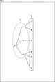
- node b to node d belong to node a
- points F to H belong to node b
- point J belongs to node c
- points K and point L belong to node d.
- Node a, node b, and node d are Octree-encoded
- node c is encoded by applying DCM (Direct Coding Mode).
- node a At that time, processing is started from node a, and then node b, node c, and node d are processed.
- the processing order of the node b, the node c, and the node d is not defined, and the processing can be performed in parallel.
- the node c is encoded by applying DCM, the point J is generally output earlier than the other points.
- points F to H are output as decoding results by processing the node b, but the output order of these is not specified.
- the points K and L are output as the decoding result, but the output order of these is not specified.
- the output order of points F to H is in no particular order
- the output order of points K and L is in no particular order
- the output order of points F to H and points K and L is in no particular order.
- the output order of the geometry data at each point has a certain degree of freedom, so there is a risk that it will not match the processing order of the attribute data. That is, it was not guaranteed that the geometry data of each point was output in the processing order of the attribute data. Therefore, in order to process the attribute data in the above-mentioned processing order, it is necessary to perform the point rearrangement processing using the above-mentioned geometry data.
- this sorting process has a high calculation cost, that is, a large processing load. That is, the processing amount and processing time of this sorting process are not small. Therefore, there is a possibility that the load of the decoding process of the coded data of the point cloud will increase by performing this sorting process. For example, the calculation cost increases due to this sorting process, which may make it difficult to process the decoding of the coded data of the point cloud in real time. Therefore, in order to reliably realize the real-time processing of decoding the coded data of the point cloud, there is a risk that the implementation cost will increase.
- the output order of the decoding results of the geometry data is set to a predetermined order.
- the geometry data is encoded so that the output order of the decoding results of the geometry data is guaranteed to be in a predetermined order.
- the encoded data of the geometry data is decoded so that the decoding results are output in a predetermined order.
- the point sorting process becomes unnecessary, it is possible to suppress an increase in the load of the point cloud coded data decoding process. Therefore, it is possible to suppress an increase in the implementation cost for surely realizing the real-time processing of decoding the coded data of the point cloud.
- the output order is fixed and becomes known. Therefore, since the point reordering process becomes unnecessary, it is possible to suppress an increase in the load of the point cloud coded data decoding process.
- This predetermined order may be any order as long as it is known when decoding the coded data of the geometry data.
- this predetermined order may be the Morton Order.
- this predetermined order may be used as the processing order of the attribute data. That is, the output order of the decoding result of the geometry data may be the same as the processing order of the attribute data.
- the geometry data (position information) of a point cloud that expresses a three-dimensional object as a set of points and the decoding result of the coded data of the geometry data is in the processing order of the attribute data (attribute information) of the point cloud. It may be encoded in the order in which it is output, and the encoded data may be generated.
- the geometry data (position information) of a point cloud that expresses a three-dimensional object as a set of points is obtained, and the decoding result of the coded data of the geometry data is the attribute data (attribute) of the point cloud. It may be provided with a coding unit that encodes in the order of output in the processing order of information) and generates the encoded data.
- the method of encoding the geometry data is arbitrary.
- CABAC Context-based Adaptive Binary Arithmetic Code
- the encoded data are decoded in the same order as the coding order. Therefore, in this case, by encoding the geometry data in the processing order of the attribute data, it is guaranteed that the geometry data of the decoding result is output in the same order as the processing order of the attribute data at the time of decoding. ..
- the encoded data of the position information of the point cloud that expresses a three-dimensional object as a set of points may be decoded, and the decoding result may be output in the processing order of the attribute information of the point cloud.
- a decoding unit that decodes the coded data of the position information of the point cloud that expresses a three-dimensional object as a set of points and outputs the decoding result in the processing order of the attribute information of the point cloud. You may prepare.
- the geometry data of the decoding result is output in the same order as the processing order of the attribute data, so the point sorting process becomes unnecessary. Therefore, it is possible to suppress an increase in the load of the decoding process of the coded data of the point cloud. Therefore, it is possible to suppress an increase in the implementation cost for surely realizing the real-time processing of decoding the coded data of the point cloud.
- the method of decoding the geometry data is arbitrary as long as it corresponds to the coding method.
- the context is used in decoding the encoded data, so the encoded data of the geometry data is arranged in the order (that is, the encoding order of the geometry data). ) May be decoded.
- the output order of the decoding results may be any order.
- the decoding results may be output in Morton order (that is, attribute data may be processed in Morton order). By outputting in the Morton order, it is guaranteed that adjacent points in the output order are spatially close to each other.
- the geometry data may be tree-structured. Further, as shown in "Method 1-3" described in the fourth column from the top of the table shown in FIG. 2, the output order of the decoding results is set to a predetermined order (for example, of the attribute data) at each node of the tree structure. It may be guaranteed that the processing order, Morton order, etc.) are used.
- the tree-structured geometry data may be encoded in the order in which the decoding results are output in the processing order of the point cloud attribute data at each node of the tree structure.
- the coded data of the tree-structured geometry data may be decoded, and the decoding results may be output in the processing order of the point cloud attribute data at each node of the tree structure.
- this tree structure may be anything. For example, it may be Octree. Further, for example, it may be a KD-tree.
- ⁇ DCM> As the coding method of the tree-structured geometry data, not only the method using the tree structure (for example, Octtree coding using Octree) but also the method applying DCM (Direct Coding Mode) should be used. You may.
- this DCM is applied and the processing target node directly or indirectly from the processing target node to the processing target node.
- the relative distance (in each direction of xyz) to each leaf (point) to which it belongs is determined and encoded.
- the "directly belonging node” refers to a node that hangs from the other node in the tree structure.
- a node that directly belongs to the processing target node indicates a node that belongs to the processing target node and is one layer lower than the processing target node (so-called child node).
- the "indirectly belonging node” refers to a node that hangs from the other node via another node in the tree structure.
- a node indirectly belonging to a processing target node indicates a node that belongs to the processing target node via another node and is two or more layers lower than the processing target node (for example, a grandchild node).
- the DCM by applying the DCM, it is possible to omit the coding / decoding of the nodes in the intermediate layer between the processing target node and each leaf directly or indirectly belonging to the processing target node.
- each leaf belonging directly or indirectly to the processing target node can be encoded / decoded. Therefore, it is possible to suppress an increase in the coding / decoding load.
- control information regarding the output order of the decoding result of the point to which the DCM is applied is signaled (encoding side). It may be transmitted from to the decoding side).
- the geometry data at sparse points is encoded by applying DCM, the encoded data of the geometry data is generated, and further, the control information regarding the output order of the decoding result of the encoded data ( (Also referred to as DCM order information) may be generated.
- DCM order information the control information regarding the output order of the decoding result of the encoded data
- the decoding result of the encoded data of the geometry data encoded by applying the DCM may be output in the output order indicated by the DCM order information.
- this DCM order information may be any information as long as it can indicate the output order of the decoding result of the point to which the DCM is applied.
- the DCM order information may include information indicating the output order of the decoding result of the point to which the DCM is applied in order from the beginning.
- the DCM order information indicates the output order of the decoding result of the point to which the DCM is applied, as the difference value from the output order of the decoding result of the point to which the DCM is applied, which is output immediately before. It may be included.
- the DCM order information may include information indicating the output order of the decoding result of the point to which the DCM is applied as a difference value from a predetermined reference order.
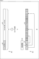
- nodes a to d and points F to L are configured in the same manner as in the case of FIG. Node a belongs to node e. Point M and point L belonging to this node e are encoded / decoded by applying DCM.
- the points F to N surrounded by the solid square 21 are output in the output order as shown by the arrow 22 as described above.
- the output order of the decoding results of the points belonging to the Octree-encoded node is guaranteed as described above. That is, the decoding results of point F, point G, point H, point K, and point L are output in the order of point F ⁇ point G ⁇ point H ⁇ point K ⁇ point L.
- DCM is applied to point M, point J, and point N, they are not always processed in the order shown in FIG. Therefore, the DCM order information is used to output these points in the correct order.
- the DCM order information may indicate the output order of the decoding result in the order from the beginning (for example, the decoding order).
- the DCM order information indicates the output order of the decoding result of the point M as "2", the output order of the decoding result of the point J as "5", and the output order of the decoding result of the point N as "6". Is shown.
- the DCM order information may indicate the output order of the decoding result as a difference value from the output order of the decoding result of the point to which the DCM output immediately before it is applied.
- the DCM order information indicates that the output order of the decoding result of the point M is "2" (the value obtained by subtracting the head “0" from the output order "2" of the decoding result of the point M).
- the DCM order information indicates that the output order of the decoding result of the point J is "3" (the value obtained by subtracting the output order "2" of the decoding result of the point M from the output order "5" of the decoding result of the point J). ..
- the DCM order information indicates that the output order of the decoding result of the point N is "1" (the value obtained by subtracting the output order "5" of the decoding result of the point J from the output order "6" of the decoding result of the point N). ..
- the code amount of the DCM order information can be reduced as compared with the case where the output order of the decoding result is shown in the order from the beginning (for example, the decoding order). That is, it is possible to suppress a decrease in coding efficiency.
- the DCM order information may indicate the output order of the decoding result as a difference value from a predetermined reference order.
- a grid unit that divides each predetermined number of points may be provided, and the difference value may be initialized (for example, set to "0") in the grid unit.
- the alternate long and short dash line 23 indicates one of the grid units. That is, in the case of this example, a grid unit is provided for every five points.
- the DCM order information indicates that the output order of the decoding result of point M is "2" (the value obtained by subtracting the leading "0" from the output order "2" of the decoding result of point M). Further, the DCM order information indicates that the output order of the decoding result of the point J is "3" (the value obtained by subtracting the output order "2” of the decoding result of the point M from the output order "5" of the decoding result of the point J). .. Further, the DCM order information indicates that the output order of the decoding result of the point N is "1” (the value obtained by subtracting the grid unit "5" indicated by the alternate long and short dash line 23 from the output order "6" of the decoding result of the point N). .. In FIG. 3, it is represented as "1'" to indicate that the difference value has been initialized.
- the above DCM order information is generated and transmitted to the decoding side.
- the transmitted DCM order information is acquired, and the output order of the decoding result of the point to which the DCM is applied is controlled based on the DCM order information. That is, the decoding result of the point to which DCM is applied is output in the correct output order.
- the decoding result of the point to which the DCM is applied is inserted at the position of the correct output order in the row of the decoding result of the Octree coded data arranged in the output order.
- the coded data of the tree-structured geometry data as described above can be decoded in a scalable manner. That is, the geometry data can be decoded at a resolution of a layer other than the lowest layer (a layer higher than the lowest layer).
- the position (output order) of the points to which the above-mentioned DCM is applied may change depending on the hierarchy. For example, as shown in FIG. 4, it is assumed that the decoding results of each node (point) in the hierarchy surrounded by the solid line square 31 are output in the order shown by the arrow 32.
- control information even in the intermediate layer of such a tree structure. May be generated. For example, for a point to which DCM is applied, control information (DCM order information) is generated for all layers (or some layers) from the processing target node to which the encoding to which DCM is applied is performed. You may do so.
- control information (DCM order information) may be signaled (transmitted from the coding side to the decoding side). Further, the decoding side may control the output order of the decoding result of the point to which the DCM is applied based on such control information (DCM order information).
- control information may include information on the output order of the decoding result in the middle layer of the tree structure.
- control information may represent the output order of the decoding result as in the case of the lowest layer described above.
- the control information may indicate the output order of the decoding result of the point to which the DCM is applied in the order from the beginning (for example, the decoding order).
- the control information in that case indicates the output order of the decoding result of the point M as "1", the output order of the decoding result of the point J as "3", and the output of the decoding result of the point N.
- the ranking is shown as "4".
- control information indicates the output order of the decoding result of the point to which the DCM is applied by the difference value from the output order of the decoding result of the point to which the DCM is applied, which is output immediately before. You may.
- the control information in that case indicates that the output order of the decoding result of the point M is "1" (the value obtained by subtracting the leading "0" from the output order "1" of the decoding result of the point M).
- the output order of the decoding result of point J is indicated as “2" (the value obtained by subtracting the output order "1" of the decoding result of point M from the output order "3" of the decoding result of point J), and the decoding result of point N is The output rank is shown as “1” (a value obtained by subtracting the output rank "3" of the decoding result of the point J from the output rank "4" of the decoding result of the point N).
- the code amount of the control information can be reduced as compared with the case where the output order of the decoding result is shown in the order from the beginning (for example, the decoding order). That is, it is possible to suppress a decrease in coding efficiency.
- control information of the point to which the DCM is applied may indicate the output order of the decoding result as a difference value from a predetermined reference order.
- a grid unit that divides each predetermined number of points may be provided, and the difference value may be initialized (for example, set to "0") in the grid unit.
- the alternate long and short dash line 33 indicates one of the grid units. That is, in the case of this example, a grid unit is provided for every three points.
- the control information in that case indicates that the output order of the decoding result of the point M is "1" (the value obtained by subtracting the head “0” from the output order "1" of the decoding result of the point M).
- the output order of the decoding result of point J is indicated as “2” (the value obtained by subtracting the output order "1" of the decoding result of point M from the output order "3" of the decoding result of point J), and the decoding result of point N is
- the output rank is shown as "1" (the value obtained by subtracting the grid unit "3" indicated by the alternate long and short dash line 23 from the output rank "4" of the decoding result of the point N). In FIG. 4, it is represented as "1'" to indicate that the difference value has been initialized.
- the code amount of the control information can be reduced as compared with the case where the output order of the decoding result is indicated by the difference value from the point to which the previous DCM is applied. That is, the reduction in coding efficiency can be suppressed.
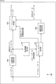
- the coded data 41 of the points encoded by applying DCM and the coded data 42 of the Octree-encoded points are configured as different data from each other and are not arranged in the processing order.
- the Octree-encoded points are not in the order of processing. Therefore, it is necessary to sort the decoding result of the coded data of each point in the processing order of the attribute data (for example, Morton order).
- the bit stream 50 includes the coded data 51 of the points encoded by applying DCM and the Octree code. It has coded data 52 of the converted points and DCM order information 53.
- the DCM order information 53 indicates the output order of the decoding result of each point to which the DCM is applied. Therefore, on the decoding side, the decoding result of each point to which the DCM is applied is inserted into the correct position of the Octree-encoded point group based on the DCM order information 53.
- the control information transmission method as described above is arbitrary. That is, the control information may be transmitted by a predetermined transmission method as in "Method 1-6" described in the seventh row from the top of the table shown in FIG.
- the control information may be included in the coded data of the geometry data.
- the control information may be transmitted as data different from the encoded data of the geometry data.
- the control information may be associated with the coded data of the geometry data by using the identification information or the like.
- the control information may include the identification information of the geometry data of the corresponding data unit (for example, slice).
- FIG. 6 is a block diagram showing an example of a configuration of a coding device, which is an aspect of an information processing device to which the present technology is applied.
- the coding device 100 shown in FIG. 6 is a device that encodes a point cloud (3D data).
- the coding device 100 includes ⁇ 1.
- the point cloud is encoded by applying the above-mentioned technology in Guarantee of output order of decoding results>.
- FIG. 6 shows the main things such as the processing unit and the data flow, and not all of them are shown in FIG. That is, in the coding apparatus 100, there may be a processing unit that is not shown as a block in FIG. 6, or there may be a processing or data flow that is not shown as an arrow or the like in FIG.
- the coding device 100 includes a position information coding unit 101, a position information decoding unit 102, a point cloud generation unit 103, an attribute information coding unit 104, and a bitstream generation unit 105.
- the position information coding unit 101 encodes the geometry data (position information) of the point cloud (3D data) input to the coding device 100. For example, the position information coding unit 101 stratifies the geometry data to generate an Octree, and encodes the Octree. Further, for example, the position information coding unit 101 encodes the geometry data of sparse points by applying DCM.
- the position information coding unit 101 is ⁇ 1.
- the above-mentioned technique is applied in Guarantee of output order of decoding results> to encode geometry data.
- the position information coding unit 101 Octreeizes and encodes the geometry data so that the decoding result of the geometry data is output in the processing order of the attribute data.
- the position information coding unit 101 supplies the coded data of the generated geometry data to the position information decoding unit 102 and the bit stream generation unit 105.
- the position information decoding unit 102 acquires the coded data of the geometry data supplied from the position information coding unit 101, and decodes the coded data.
- This decoding method is arbitrary as long as it corresponds to the coding by the position information coding unit 101. For example, processing such as filtering for denoise and dequantization may be performed.
- the position information decoding unit 102 supplies the generated geometry data (decoding result) to the point cloud generation unit 103.
- the point cloud generation unit 103 acquires the attribute data (attribute information) of the point cloud input to the coding device 100 and the geometry data (decoding result) supplied from the position information decoding unit 102.
- the point cloud generation unit 103 performs a process (recolor process) of matching the attribute data with the geometry data (decoding result).
- the point cloud generation unit 103 supplies the attribute data corresponding to the geometry data (decoding result) to the attribute information coding unit 104.
- the point cloud generation unit 103 has ⁇ 1.
- the above-mentioned technology is applied in Guarantee of output order of decoding results> to generate and encode DCM order information indicating the output order of decoding results at the point where DCM is applied.
- the point cloud generation unit 103 supplies the generated encoded data of the DCM order information to the bitstream generation unit 105.
- the attribute information coding unit 104 acquires the geometry data (decoding result) and the attribute data supplied from the point cloud generation unit 103.
- the attribute information coding unit 104 encodes the attribute data using the geometry data (decoding result) and generates the coded data of the attribute data.
- the attribute information coding unit 104 supplies the coded data of the generated attribute data to the bitstream generation unit 105.
- the bitstream generation unit 105 acquires the coded data of the geometry data supplied from the position information coding unit 101. Further, the bitstream generation unit 105 acquires the coded data of the attribute data supplied from the attribute information coding unit 104. Further, the bitstream generation unit 105 acquires the encoded data of the DCM order information supplied from the point cloud generation unit 103. The bitstream generation unit 105 generates a bitstream including these coded data. The bitstream generation unit 105 outputs the generated bitstream to the outside of the encoding device 100.
- the coding device 100 does not need to perform the point sorting process, so that it is possible to suppress an increase in the load of the point cloud coded data decoding process. Therefore, the coding device 100 can suppress an increase in the mounting cost for surely realizing the real-time processing of decoding the coded data of the point cloud.
- each of these processing units position information coding unit 101 to bitstream generation unit 105) of the coding device 100 has an arbitrary configuration.
- each processing unit may be configured by a logic circuit that realizes the above-mentioned processing.
- each processing unit has, for example, a CPU (Central Processing Unit), a ROM (Read Only Memory), a RAM (Random Access Memory), and the like, and the above-mentioned processing is realized by executing a program using them. You may do so.
- each processing unit may have both configurations, and a part of the above-mentioned processing may be realized by a logic circuit, and the other may be realized by executing a program.
- the configurations of the respective processing units may be independent of each other. For example, some processing units realize a part of the above-mentioned processing by a logic circuit, and some other processing units execute a program.
- the above-mentioned processing may be realized by the other processing unit by both the logic circuit and the execution of the program.
- FIG. 7 is a block diagram showing a main configuration example of the position information coding unit 101 (FIG. 6). Note that FIG. 7 shows the main things such as the processing unit and the data flow, and not all of them are shown in FIG. 7. That is, in the position information coding unit 101, there may be a processing unit that is not shown as a block in FIG. 7, or there may be a processing or data flow that is not shown as an arrow or the like in FIG. 7.
- the position information coding unit 101 includes a bounding box setting unit 111, a voxel setting unit 112, a mode selection unit 113, an Octree coding unit 114, and a DCM coding unit 115.
- the bounding box setting unit 111 performs processing related to the setting of the bounding box. For example, the bounding box setting unit 111 acquires the geometry data of the point cloud data input to the coding device 100. The bounding box setting unit 111 sets the bounding box for the geometry data. The bounding box is information for normalizing the geometry data to be encoded. Voxels are created based on this bounding box. The bounding box setting unit 111 supplies information about the bounding box to the voxel setting unit 112 together with the geometry data.
- the voxel setting unit 112 performs processing related to voxel setting. For example, the voxel setting unit 112 acquires the geometry data supplied from the bounding box setting unit 111 and information on the bounding box. Further, the voxel setting unit 112 sets the voxels by dividing the bounding box set for the geometry data based on the information. That is, the voxel setting unit 112 performs voxelization (quantization of the position of each point) of the geometry data. The voxel setting unit 112 supplies the voxel data, which is the geometry data converted into voxels in this way, to the mode selection unit 113.
- the mode selection unit 113 performs processing related to selection of a coding method (mode). For example, the mode selection unit 113 acquires voxel data supplied from the voxel setting unit 112. Further, the mode selection unit 113 selects a coding method (mode) for each voxel (node in Octree). That is, the mode selection unit 113 selects whether the voxel to be processed is Octree-encoded or encoded by applying DCM (also referred to as DCM encoding).
- DCM also referred to as DCM encoding
- the mode selection unit 113 determines whether or not the voxels to be processed are sparse. When it is determined that the data is not sparse based on a predetermined condition, the mode selection unit 113 selects Octree coding as the coding method, and supplies the voxel data to be processed to the Octree coding unit 114. When it is determined that the data is sparse based on a predetermined condition, the mode selection unit 113 selects DCM coding as the coding method and supplies the voxel data to be processed to the DCM coding unit 115.
- Octree coding unit 114 performs processing related to coding using Octree. For example, the Octree coding unit 114 acquires the voxel data to be processed supplied from the mode selection unit 113. The Octree coding unit 114 uses the voxel data to generate Octree data (ChildMask) of the node to be processed. The Octree coding unit 114 encodes the Octree data of the processing target node by a predetermined method and generates the coded data.
- the Octree coding unit 114 is ⁇ 1. Encoding is performed by applying the above-mentioned technique (for example, "method 1" (which may include methods 1-1 to 1-3) in FIG. 2) described in Guarantee of output order of decoding results>. That is, the Octree coding unit 114 encodes the Octree data of the processing target node so that the decoding result of the geometry data is output in the processing order of the attribute data. For example, the Octree coding unit 114 encodes the Octree data of the processing target node in the order in which the decoding results of the geometry data are output in the Morton order. For example, the Octree encoding unit 114 encodes the decoding results in the order in which the decoding results are output in the processing order of the point cloud attribute data at each node of the Octree.
- “method 1" which may include methods 1-1 to 1-3) in FIG. 2
- Guarantee of output order of decoding results> the Octree coding unit 114 encodes the Octree data of the processing
- the Octree coding unit 114 transfers the coded data (encoded data of the voxel data of the processing target node) generated by performing the coding in this way to the position information decoding unit 102 and the bitstream generation unit 105 (both in FIG. 6). Supply.
- the DCM coding unit 115 performs processing related to coding using DCM. For example, the DCM coding unit 115 acquires the voxel data to be processed supplied from the mode selection unit 113. The DCM coding unit 115 encodes the voxel data by applying DCM to generate coded data. For example, the DCM coding unit 115 uses the voxel data to encode the relative distance from the processing target node to the leaf to generate the coded data. The DCM coding unit 115 supplies the generated coded data to the position information decoding unit 102 and the bitstream generation unit 105 (both of FIG. 6).
- the position information coding unit 101 can perform Octtree coding so that the output order of the decoding results of the geometry data is guaranteed to be a predetermined order. Therefore, since the coding device 100 does not need to perform the point sorting process, it is possible to suppress an increase in the load of the point cloud coded data decoding process.
- each processing unit may be configured by a logic circuit that realizes the above-mentioned processing.
- each processing unit may have, for example, a CPU, ROM, RAM, etc., and execute a program using them to realize the above-mentioned processing.
- each processing unit may have both configurations, and a part of the above-mentioned processing may be realized by a logic circuit, and the other may be realized by executing a program.
- the configurations of the respective processing units may be independent of each other. For example, some processing units realize a part of the above-mentioned processing by a logic circuit, and some other processing units execute a program.
- the above-mentioned processing may be realized by the other processing unit by both the logic circuit and the execution of the program.
- FIG. 8 is a block diagram showing a main configuration example of the point cloud generation unit 103 (FIG. 6). Note that FIG. 8 shows the main things such as the processing unit and the data flow, and not all of them are shown in FIG. That is, in the point cloud generation unit 103, there may be a processing unit that is not shown as a block in FIG. 8, or there may be a processing or data flow that is not shown as an arrow or the like in FIG.
- the point cloud generation unit 103 includes a Morton code conversion unit 121, a sorting unit 122, a DCM order information generation unit 123, a DCM order information coding unit 124, and a recolor processing unit 125.
- the Morton code conversion unit 121 converts the geometry data (decoding result) supplied from the position information decoding unit 102 (FIG. 6) into a Morton code. That is, the Morton code conversion unit 121 maps points in the three-dimensional space to one dimension by using the Morton code. The Morton code conversion unit 121 supplies the geometry data of each point with the Morton code to the sorting unit 122.
- the sorting unit 122 acquires the geometry data supplied from the Morton code conversion unit 121, and sorts the geometry data based on the value of the Morton code. That is, the sorting unit 122 sorts the geometry data of each point in the Morton order. The sorting unit 122 supplies the geometry data of each point sorted in the Morton order to the DCM order information generation unit 123 and the recolor processing unit 125.
- the DCM order information generation unit 123 identifies a point to which DCM is applied at the time of encoding among the geometry data of each point sorted in Morton order, and control information indicating the output order of the decoding result of that point. Generates DCM order information that is.
- the DCM order information may include information indicating the output order of the decoding result of the point to which the DCM is applied in the order from the beginning.
- the DCM order information indicates the output order of the decoding result of the point to which the DCM is applied, as the difference value from the output order of the decoding result of the point to which the DCM is applied, which is output immediately before. It may be included.
- the DCM order information may include information indicating the output order of the decoding result of the point to which the DCM is applied as a difference value from a predetermined reference order.
- the DCM order information generation unit 123 may also generate DCM order information indicating the output order of the point to which the DCM is applied in the middle layer of the Octree. That is, the DCM order information may also include information on the output order of the decoding result in the middle layer of Octree.
- the DCM order information generation unit 123 supplies the generated DCM order information to the DCM order information coding unit 124.
- the DCM order information coding unit 124 performs processing related to encoding the DCM order information. For example, the DCM order information coding unit 124 acquires the DCM order information supplied from the DCM order information generation unit 123. The DCM order information coding unit 124 encodes the acquired DCM order information and generates coded data. This coding method is arbitrary. The DCM order information coding unit 124 supplies the generated encoded data of the DCM order information to the bitstream generation unit 105 (FIG. 6).
- the recolor processing unit 125 performs processing related to processing for matching attribute data with geometry data (recolor processing). For example, the recolor processing unit 125 acquires the attribute data of the point cloud input to the coding device 100. Further, the recolor processing unit 125 acquires the geometry data of each point sorted in the Morton order supplied from the sorting unit 122.
- the recolor processing unit 125 performs a process (recolor processing) to match the acquired attribute data with the acquired geometry data, and generates point cloud data.
- the recolor processing unit 125 supplies the generated point cloud data to the attribute information coding unit 104 (FIG. 6).
- the point cloud generation unit 103 can generate DCM order information and transmit it to the decoding side.
- the decoding result of the points encoded by applying DCM can also be output in an appropriate output order. Therefore, since it is not necessary to rearrange the points at the time of decoding, the coding apparatus 100 can suppress an increase in the mounting cost for surely realizing the real-time processing of decoding the coded data of the point cloud. it can.
- each of these processing units (Morton code conversion unit 121 to recolor processing unit 125) of the point cloud generation unit 103 has an arbitrary configuration.
- each processing unit may be configured by a logic circuit that realizes the above-mentioned processing.
- each processing unit may have, for example, a CPU, ROM, RAM, etc., and execute a program using them to realize the above-mentioned processing.
- each processing unit may have both configurations, and a part of the above-mentioned processing may be realized by a logic circuit, and the other may be realized by executing a program.
- the configurations of the respective processing units may be independent of each other. For example, some processing units realize a part of the above-mentioned processing by a logic circuit, and some other processing units execute a program.
- the above-mentioned processing may be realized by the other processing unit by both the logic circuit and the execution of the program.
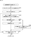
- the coding device 100 encodes the data in the point cloud by executing the coding process. An example of the flow of this coding process will be described with reference to the flowchart of FIG.
- the position information coding unit 101 of the coding device 100 encodes the input point cloud geometry data (position information) in step S101 to generate the coded data of the geometry data. To do. At that time, the position information coding unit 101 is set to ⁇ 1. The processing is performed by applying the above-mentioned technology in Guarantee of output order of decoding results>. The details of the position information coding process will be described later.
- step S102 the position information decoding unit 102 decodes the coded data of the geometry data generated in step S101 and generates the position information.
- step S103 the point cloud generation unit 103 performs recolor processing using the input point cloud attribute data (attribute information) and the geometry data (decoding result) generated in step S102, and obtains the attribute data. Generate point cloud data corresponding to geometry data. At that time, the point cloud generation unit 103 has ⁇ 1. Applying the above-mentioned technology in Guarantee of output order of decoding results>, DCM order information indicating the output order of decoding results at the point to which DCM is applied is generated and encoded. The details of the point cloud generation process will be described later.
- step S104 the attribute information coding unit 104 encodes the attribute data recolored in step S103 by executing the attribute information coding process, and generates the coded data of the attribute data.
- the bit stream generation unit 105 includes the coded data of the geometry data generated in step S101, the coded data of the DCM order information generated in step S103, and the code of the attribute data generated in step S104. Generates and outputs a bit stream containing the converted data.
- step S105 When the process of step S105 is completed, the coding process is completed.
- the coding apparatus 100 can eliminate the need for the point sorting processing at the time of decoding, so that the load of the point cloud coding data decoding processing increases. It can be suppressed. Therefore, the coding device 100 can suppress an increase in the mounting cost for surely realizing the real-time processing of decoding the coded data of the point cloud.
- the bounding box setting unit 111 sets the bounding box for the geometry data to be processed in step S121.
- step S122 the voxel setting unit 112 sets the voxel based on the bounding box set in step S121, and quantizes the geometry data of each point.
- step S123 the mode selection unit 113 selects voxel data to be processed from the voxels set in step S122 according to the Morton order.
- step S124 the mode selection unit 113 determines whether or not to apply DCM to the voxel data to be processed. If it is determined to be sparse based on a predetermined condition, the process proceeds to step S125.
- step S125 the DCM coding unit 115 DCM-encodes the voxel data to be processed.
- the process of step S125 proceeds to step S127.
- step S124 If it is determined in step S124 that the DCM is not applied to the voxel data to be processed, the process proceeds to step S126.
- step S126 the Octree coding unit 114 has ⁇ 1.
- the above-mentioned technology is applied in Guarantee of output order of decoding result>, and Octtree coding is performed on the voxel data to be processed so that the output order of the decoding result is Morton order.
- step S126 the process proceeds to step S127.
- step S127 the mode selection unit 113 determines whether or not all the voxel data has been processed. If there is unprocessed voxel data, the process returns to step S123, and the subsequent processes are repeated. That is, each process of step S123 to step S127 is executed for each voxel data.
- step S127 when it is determined that all the voxel data has been processed, the position information coding process is completed, and the process returns to FIG.
- the coding apparatus 100 can eliminate the need for the point sorting processing at the time of decoding, so that the load of the point cloud coding data decoding processing increases. It can be suppressed. Therefore, the coding device 100 can suppress an increase in the mounting cost for surely realizing the real-time processing of decoding the coded data of the point cloud.
- the Morton code conversion unit 121 (FIG. 8) of the point cloud generation unit 103 converts the geometry data into the Morton code in step S141.
- step S142 the sorting unit 122 sorts the geometry data in Morton order based on the Morton code assigned in step S121.
- step S143 the DCM order information generation unit 123 identifies the points to which the DCM is applied at the time of coding among the geometry data for each point sorted in the Morton order, and outputs the decoding results of the points. Generates DCM order information indicating. At that time, the DCM order information generation unit 123 has ⁇ 1.
- the above-mentioned technology is applied in Guarantee of output order of decoding results> to generate DCM order information.
- step S144 the DCM order information coding unit 124 encodes the DCM order information generated in step S143 and generates encoded data.
- step S145 the recolor processing unit 125 performs a process (recolor processing) to match the acquired attribute data with the acquired geometry data, and generates point cloud data.
- step S145 When the process of step S145 is completed, the point cloud generation process is completed, and the process returns to FIG.
- the coding apparatus 100 can eliminate the need for the point sorting processing at the time of decoding, so that the load of the point cloud coding data decoding processing increases. It can be suppressed. Therefore, the coding device 100 can suppress an increase in the mounting cost for surely realizing the real-time processing of decoding the coded data of the point cloud.
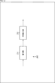
- FIG. 12 is a block diagram showing an example of a configuration of a decoding device, which is an aspect of an information processing device to which the present technology is applied.
- the decoding device 200 shown in FIG. 12 is a device that decodes the coded data of the point cloud (3D data).
- the decoding device 200 has ⁇ 1. Guarantee of output order of decoding results> The above-mentioned technology is applied to decode the coded data of the point cloud.
- FIG. 12 shows the main things such as the processing unit and the data flow, and not all of them are shown in FIG. That is, in the decoding device 200, there may be a processing unit that is not shown as a block in FIG. 12, or there may be a processing or data flow that is not shown as an arrow or the like in FIG.
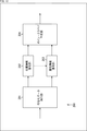
- the decoding device 200 includes a coded data extraction unit 201, a position information decoding unit 202, an attribute information decoding unit 203, and a point cloud generation unit 204.
- the coded data extraction unit 201 acquires and holds a bit stream input to the decoding device 200.
- the coded data extraction unit 201 extracts coded data of geometry data (position information) and attribute data (attribute information) from the bit stream. At that time, the coded data extraction unit 201 can extract the coded data of all layers from the bit stream. Further, for example, the coded data from the highest layer to the layer specified by the user, the application, or the like (that is, the coded data of a part of the layers) can be extracted from the bit stream.
- the coded data extraction unit 201 supplies the coded data of the extracted geometry data to the position information decoding unit 202.
- the coded data extraction unit 201 supplies the coded data of the extracted attribute data to the attribute information decoding unit 203.
- the position information decoding unit 202 acquires the coded data of the geometry data supplied from the coded data extraction unit 201.
- the position information decoding unit 202 decodes the coded data of the geometry data and generates the geometry data (decoding result). At that time, the position information decoding unit 202 has ⁇ 1.
- Geometry data is decoded by applying the above-mentioned technique in Guarantee of output order of decoding results>. That is, the position information decoding unit 202 decodes the coded data of the geometry data and outputs the decoding result in the processing order of the attribute data of the point cloud.
- the position information decoding unit 202 supplies the generated geometry data (decoding result) to the attribute information decoding unit 203 and the point cloud generation unit 204.
- the attribute information decoding unit 203 acquires the coded data of the attribute data supplied from the coded data extraction unit 201.
- the attribute information decoding unit 203 acquires the geometry data (decoding result) supplied from the position information decoding unit 202.
- the attribute information decoding unit 203 decodes the coded data of the attribute data using the geometry data, and generates the attribute data (decoding result).
- the attribute information decoding unit 203 supplies the generated attribute data (decoding result) to the point cloud generation unit 204.
- the point cloud generation unit 204 acquires the geometry data (decoding result) supplied from the position information decoding unit 202.
- the point cloud generation unit 204 acquires the attribute data (decoding result) supplied from the attribute information decoding unit 203.
- the point cloud generation unit 204 generates a point cloud (decoding result) using the geometry data (decoding result) and attribute data (decoding result).
- the point cloud generation unit 204 outputs the generated point cloud (decoding result) data to the outside of the decoding device 200.
- the decoding device 200 can suppress an increase in the load of the decoding process of the coded data of the point cloud. Therefore, it is possible to suppress an increase in the implementation cost for surely realizing the real-time processing of decoding the coded data of the point cloud.
- each processing unit may be configured by a logic circuit that realizes the above-mentioned processing.
- each processing unit may have, for example, a CPU, ROM, RAM, etc., and execute a program using them to realize the above-mentioned processing.
- each processing unit may have both configurations, and a part of the above-mentioned processing may be realized by a logic circuit, and the other may be realized by executing a program.
- the configurations of the respective processing units may be independent of each other. For example, some processing units realize a part of the above-mentioned processing by a logic circuit, and some other processing units execute a program.
- the above-mentioned processing may be realized by the other processing unit by both the logic circuit and the execution of the program.
- FIG. 13 is a block diagram showing a main configuration example of the position information decoding unit 202 (FIG. 12). Note that FIG. 13 shows the main things such as the processing unit and the data flow, and not all of them are shown in FIG. That is, in the position information decoding unit 202, there may be a processing unit that is not shown as a block in FIG. 13, or there may be a processing or data flow that is not shown as an arrow or the like in FIG.
- the position information decoding unit 202 has a decoding unit 211 and a DCM insertion unit 212.
- the decoding unit 211 performs processing related to decoding geometry data. For example, the position information decoding unit 202 acquires the coded data of the geometry data supplied from the coded data extraction unit 201. The decoding unit 211 decodes the acquired encoded data and generates (restores) geometry data.
- the decoding unit 211 decodes the coded data of the DCM order information included in the coded data of the geometry data. Further, for example, the decoding unit 211 decodes the encoded data of the Octree data in the Morton order. Further, for example, the decoding unit 211 decodes the DCM-encoded coded data.
- the decoding unit 211 supplies the geometry data generated by decoding (which may include DCM order information, Octree data, geometry data of points to which DCM is applied (also referred to as DCM data), etc.) to the DCM insertion unit 212.
- the DCM insertion unit 212 performs processing related to controlling the output order of the geometry data at the point to which the DCM is applied. For example, the DCM insertion unit 212 acquires geometry data (which may include DCM order information, Octree data, DCM data, etc.) supplied from the decoding unit 211.
- geometry data which may include DCM order information, Octree data, DCM data, etc.
- the DCM insertion unit 212 inserts the acquired DCM data at the position of the output order indicated by the DCM order information in the column of Octtree data sorted in Morton order. That is, the DCM insertion unit 212 controls so that the DCM data is output in the output order indicated by the DCM order information corresponding to the DCM data.
- the DCM insertion unit 212 supplies the Octtree data (geometry data sorted in Morton order) into which the DCM data is inserted to the point cloud generation unit 204 (FIG. 12).
- the decoding device 200 can suppress an increase in the load of the decoding process of the coded data of the point cloud. Therefore, it is possible to suppress an increase in the implementation cost for surely realizing the real-time processing of decoding the coded data of the point cloud.
- each processing unit may be configured by a logic circuit that realizes the above-mentioned processing.
- each processing unit may have, for example, a CPU, ROM, RAM, etc., and execute a program using them to realize the above-mentioned processing.
- each processing unit may have both configurations, and a part of the above-mentioned processing may be realized by a logic circuit, and the other may be realized by executing a program.
- the configurations of the respective processing units may be independent of each other. For example, some processing units realize a part of the above-mentioned processing by a logic circuit, and some other processing units execute a program.
- the above-mentioned processing may be realized by the other processing unit by both the logic circuit and the execution of the program.
- the decoding device 200 decodes the coded data of the point cloud by executing the decoding process.
- An example of the flow of the decoding process will be described with reference to the flowchart of FIG.
- the coded data extraction unit 201 of the decoding device 200 acquires and holds the bit stream in step S201, and the geometry data (position information) and attribute data (position information) of the layer to be decoded from the bit stream. Attribute information) coded data is extracted.
- step S202 the position information decoding unit 202 decodes the coded data of the geometry data extracted in step S201 and generates the geometry data (decoding result). At that time, the position information decoding unit 202 has ⁇ 1.
- the processing is performed by applying the above-mentioned technology in Guarantee of output order of decoding results>. The details of the position information decoding process will be described later.
- step S203 the attribute information decoding unit 203 decodes the coded data of the attribute data extracted in step S201 and generates the attribute data (decoding result).
- step S204 the point cloud generation unit 204 generates point cloud data (decoding result) using the geometry data (decoding result) generated in step S202 and the attribute data (decoding result) generated in step S203. And output.
- step S204 When the process of step S204 is completed, the decryption process is completed.
- the decoding device 200 can suppress an increase in the load of the decoding process of the coded data of the point cloud. Therefore, it is possible to suppress an increase in the implementation cost for surely realizing the real-time processing of decoding the coded data of the point cloud.
- the decoding unit 211 of the position information decoding unit 202 decodes the DCM order information in step S221.
- step S222 the decoding unit 211 decodes the encoded data of the Octree data in the Morton order.
- step S223 the decoding unit 211 decodes the encoded data of the DCM data.
- step S224 the DCM insertion unit 212 transfers the DCM data decoded in step S223 to the output order indicated by the DCM order information decoded in step S221 of the Octree data in Morton order decoded in step S222. Insert it in the corresponding position. That is, the DCM insertion unit 212 controls the output order of the geometry data (decoding result) so that the DCM data is output in the output order indicated by the DCM order information. At that time, the DCM insertion portion 212 is ⁇ 1.
- the processing is performed by applying the above-mentioned technology in Guarantee of output order of decoding results>.
- step S224 When the process of step S224 is completed, the position information decoding process is completed, and the process returns to FIG.
- the decoding device 200 can suppress an increase in the load of the decoding process of the coded data of the point cloud. Therefore, it is possible to suppress an increase in the implementation cost for surely realizing the real-time processing of decoding the coded data of the point cloud.
- the output order of the decoding result of the geometry data may be an order other than the processing order of the attribute data.
- Geometry data included in the subregion 302 can be specified as a group of data. That is, only the geometry data in the partial area 302 can be easily decoded only by designating the first point (Start number) and the last point (End number) as the decoding target.
- control information other than the above-mentioned example may be signaled.
- control information for example, enabled_flag
- a control for designating a range for example, an upper limit or a lower limit of a block size, or both, a slice, a picture, a sequence, a component, a view, a layer, etc.
- Information may be transmitted.
- the series of processes described above can be executed by hardware or by software.
- the programs constituting the software are installed on the computer.
- the computer includes a computer embedded in dedicated hardware, a general-purpose personal computer capable of executing various functions by installing various programs, and the like.
- FIG. 17 is a block diagram showing a configuration example of computer hardware that executes the above-mentioned series of processes programmatically.
- the CPU Central Processing Unit
- ROM Read Only Memory
- RAM Random Access Memory
- the input / output interface 910 is also connected to the bus 904.
- An input unit 911, an output unit 912, a storage unit 913, a communication unit 914, and a drive 915 are connected to the input / output interface 910.
- the input unit 911 includes, for example, a keyboard, a mouse, a microphone, a touch panel, an input terminal, and the like.
- the output unit 912 includes, for example, a display, a speaker, an output terminal, and the like.
- the storage unit 913 includes, for example, a hard disk, a RAM disk, a non-volatile memory, or the like.
- the communication unit 914 includes, for example, a network interface.
- the drive 915 drives a removable medium 921 such as a magnetic disk, an optical disk, a magneto-optical disk, or a semiconductor memory.
- the CPU 901 loads the program stored in the storage unit 913 into the RAM 903 via the input / output interface 910 and the bus 904 and executes the above-described series. Is processed.
- the RAM 903 also appropriately stores data and the like necessary for the CPU 901 to execute various processes.
- the program executed by the computer can be recorded and applied to the removable media 921 as a package media or the like, for example.
- the program can be installed in the storage unit 913 via the input / output interface 910 by mounting the removable media 921 in the drive 915.
- This program can also be provided via wired or wireless transmission media such as local area networks, the Internet, and digital satellite broadcasting. In that case, the program can be received by the communication unit 914 and installed in the storage unit 913.
- this program can be installed in advance in ROM 902 or storage unit 913.
- the coding device 100 and the decoding device 200 have been described as application examples of the present technology, but the present technology can be applied to any configuration.
- this technology is a transmitter or receiver (for example, a television receiver or mobile phone) for satellite broadcasting, cable broadcasting such as cable TV, distribution on the Internet, and distribution to terminals by cellular communication, or It can be applied to various electronic devices such as devices (for example, hard disk recorders and cameras) that record images on media such as optical disks, magnetic disks, and flash memories, and reproduce images from these storage media.
- devices for example, hard disk recorders and cameras
- a processor as a system LSI (Large Scale Integration) or the like (for example, a video processor), a module using a plurality of processors (for example, a video module), a unit using a plurality of modules (for example, a video unit)
- a processor as a system LSI (Large Scale Integration) or the like (for example, a video processor), a module using a plurality of processors (for example, a video module), a unit using a plurality of modules (for example, a video unit)
- a processor as a system LSI (Large Scale Integration) or the like (for example, a video processor), a module using a plurality of processors (for example, a video module), a unit using a plurality of modules (for example, a video unit)
- a set for example, a video set
- this technology can be applied to a network system composed of a plurality of devices.
- the present technology may be implemented as cloud computing that is shared and jointly processed by a plurality of devices via a network.
- this technology is implemented in a cloud service that provides services related to images (moving images) to arbitrary terminals such as computers, AV (AudioVisual) devices, portable information processing terminals, and IoT (Internet of Things) devices. You may try to do it.
- the system means a set of a plurality of components (devices, modules (parts), etc.), and it does not matter whether all the components are in the same housing. Therefore, a plurality of devices housed in separate housings and connected via a network, and a device in which a plurality of modules are housed in one housing are both systems. ..
- Systems, devices, processing units, etc. to which this technology is applied can be used in any field such as transportation, medical care, crime prevention, agriculture, livestock industry, mining, beauty, factories, home appliances, weather, nature monitoring, etc. .. The use is also arbitrary.
- the "flag” is information for identifying a plurality of states, and is not only information used for identifying two states of true (1) or false (0), but also three or more states. It also contains information that can identify the state. Therefore, the value that this "flag” can take may be, for example, 2 values of 1/0 or 3 or more values. That is, the number of bits constituting this "flag” is arbitrary, and may be 1 bit or a plurality of bits.
- the identification information (including the flag) is assumed to include not only the identification information in the bit stream but also the difference information of the identification information with respect to a certain reference information in the bit stream. In, the "flag” and “identification information” include not only the information but also the difference information with respect to the reference information.
- various information (metadata, etc.) regarding the coded data may be transmitted or recorded in any form as long as it is associated with the coded data.
- the term "associate" means, for example, to make the other data available (linkable) when processing one data. That is, the data associated with each other may be combined as one data or may be individual data.
- the information associated with the coded data (image) may be transmitted on a transmission path different from the coded data (image).
- the information associated with the coded data (image) may be recorded on a recording medium (or another recording area of the same recording medium) different from the coded data (image). Good.
- this "association" may be a part of the data, not the entire data. For example, an image and information corresponding to the image may be associated with each other in an arbitrary unit such as a plurality of frames, one frame, or a part within the frame.
- the embodiment of the present technology is not limited to the above-described embodiment, and various changes can be made without departing from the gist of the present technology.
- the configuration described as one device (or processing unit) may be divided and configured as a plurality of devices (or processing units).
- the configurations described above as a plurality of devices (or processing units) may be collectively configured as one device (or processing unit).
- a configuration other than the above may be added to the configuration of each device (or each processing unit).
- a part of the configuration of one device (or processing unit) may be included in the configuration of another device (or other processing unit). ..
- the above-mentioned program may be executed in any device.
- the device may have necessary functions (functional blocks, etc.) so that necessary information can be obtained.
- each step of one flowchart may be executed by one device, or may be shared and executed by a plurality of devices.
- the plurality of processes may be executed by one device, or may be shared and executed by a plurality of devices.
- a plurality of processes included in one step can be executed as processes of a plurality of steps.
- the processes described as a plurality of steps can be collectively executed as one step.
- the processing of the steps for writing the program may be executed in chronological order in the order described in the present specification, and may be executed in parallel or in calls. It may be executed individually at the required timing such as when it is broken. That is, as long as there is no contradiction, the processing of each step may be executed in an order different from the above-mentioned order. Further, the processing of the step for writing this program may be executed in parallel with the processing of another program, or may be executed in combination with the processing of another program.
- a plurality of technologies related to this technology can be independently implemented independently as long as there is no contradiction.
- any plurality of the present technologies can be used in combination.
- some or all of the techniques described in any of the embodiments may be combined with some or all of the techniques described in other embodiments. It is also possible to carry out a part or all of any of the above-mentioned techniques in combination with other techniques not described above.
- the present technology can also have the following configurations.
- the position information of the point cloud which expresses a three-dimensional object as a set of points, is coded in such an order that the decoding result of the coded data of the position information is output in the processing order of the attribute information of the point cloud.
- An information processing device including a coding unit for converting and generating the coded data.
- the coding unit encodes the position information in an order in which the decoding results are output in the Morton order to generate the coded data.
- the coding unit encodes the tree-structured position information in an order in which the decoding results are output in the processing order of the point cloud attribute information at each node of the tree structure.
- the information processing apparatus according to (1) or (2), which generates coded data.
- the information processing apparatus which generates coded data.
- the information processing apparatus (4) The information processing apparatus according to (3), wherein the tree structure is an Octree.
- a DCM coding unit that encodes the position information of the sparse points of the Octree by applying DCM (Direct Coding Mode) to generate the coded data of the position information.
- the information processing apparatus according to (4), further comprising a generation unit that generates control information regarding an output order of a decoding result of the coded data generated by the DCM coding unit.
- the control information includes information indicating the output order of the decoding results in order from the beginning.
- the control information is a difference value from the output order of the decoding result of the coded data of the position information encoded by applying the DCM which is output immediately before the output order of the decoding result.
- the information processing apparatus according to (5) which includes the information indicated by.
- the control information includes information indicating the output order of the decoding result as a difference value from a predetermined reference order.
- the information processing apparatus according to any one of (5) to (8), wherein the control information also includes information regarding an output order of the decoding result in the intermediate layer of the tree structure.
- the position information of the point cloud which expresses a three-dimensional object as a set of points, is coded in such an order that the decoding result of the coded data of the position information is output in the processing order of the attribute information of the point cloud.
- An information processing device including a decoding unit that decodes the coded data of the position information of the point cloud that expresses a three-dimensional object as a set of points and outputs the decoding result in the processing order of the attribute information of the point cloud. .. (12) The information processing apparatus according to (11), wherein the decoding unit outputs the decoding results in Morton order. (13) The decoding unit decodes the coded data of the position information having a tree structure, and outputs the decoding result at each node of the tree structure in the processing order of the attribute information of the point cloud (11). Or the information processing apparatus according to (12). (14) The information processing apparatus according to (13), wherein the tree structure is an Octree.
- the decoding result of the coded data of the position information encoded by applying DCM is output in the output order indicated by the control information regarding the output order of the decoding result of the coded data.
- the control information includes information indicating the output order of the decoding results in order from the beginning.
- the control information is a difference value from the output order of the decoding result of the coded data of the position information encoded by applying the DCM which is output immediately before the output order of the decoding result.
- control information includes information indicating the output order of the decoding result as a difference value from a predetermined reference order.
- the control information also includes information regarding an output order of the decoding result in the intermediate layer of the tree structure.
- 100 coding device 101 position information coding unit, 102 position information decoding unit, 103 point cloud generation unit, 104 attribute information coding unit, 105 bit stream generation unit, 111 bounding box setting unit, 112 boxel setting unit, 113 mode Selection unit, 114 October coding unit, 115 DCM coding unit, 121 Morton code conversion unit, 122 sorting unit, 123 DCM order information generation unit, 124 DCM order information coding unit, 125 recolor processing unit, 200 decoding device, 201 encoded data extraction unit, 202 position information decoding unit, 203 attribute information decoding unit, 204 point cloud generation unit, 211 decoding unit, 212 DCM insertion unit
Abstract
La présente invention concerne un dispositif et un procédé de traitement d'informations permettant de supprimer l'augmentation de la charge d'un processus de décodage de données codées d'un nuage de points. Des informations de position d'un nuage de points exprimant un objet de forme tridimensionnelle en tant qu'ensemble de points sont codées dans un ordre tel que les résultats décodés de données codées des informations de position sont délivrés en sortie dans un ordre de traitement d'informations d'attribut concernant le nuage de points, et les données codées sont générées. De plus, les données codées des informations de position du nuage de points exprimant un objet de forme tridimensionnelle en tant qu'ensemble de points sont décodées, et les résultats décodés sont délivrés en sortie dans un ordre de traitement d'informations d'attribut concernant le nuage de points. La présente invention peut être appliquée, par exemple, à un dispositif de traitement d'informations, à un dispositif de traitement d'image, à un dispositif de codage, à un dispositif de décodage, à un dispositif électronique, à un procédé de traitement d'informations, ou à un programme.
Priority Applications (5)
| Application Number | Priority Date | Filing Date | Title |
|---|---|---|---|
| US17/625,940 US20220262043A1 (en) | 2019-07-17 | 2020-07-06 | Information processing apparatus and method |
| KR1020217041630A KR20220035041A (ko) | 2019-07-17 | 2020-07-06 | 정보 처리 장치 및 방법 |
| EP20839972.5A EP3989176A4 (fr) | 2019-07-17 | 2020-07-06 | Dispositif et procédé de traitement d'informations |
| CN202080050213.9A CN114128282A (zh) | 2019-07-17 | 2020-07-06 | 信息处理装置和方法 |
| JP2021532790A JPWO2021010200A1 (fr) | 2019-07-17 | 2020-07-06 |
Applications Claiming Priority (2)
| Application Number | Priority Date | Filing Date | Title |
|---|---|---|---|
| JP2019-131952 | 2019-07-17 | ||
| JP2019131952 | 2019-07-17 |
Publications (1)
| Publication Number | Publication Date |
|---|---|
| WO2021010200A1 true WO2021010200A1 (fr) | 2021-01-21 |
Family
ID=74209809
Family Applications (1)
| Application Number | Title | Priority Date | Filing Date |
|---|---|---|---|
| PCT/JP2020/026322 WO2021010200A1 (fr) | 2019-07-17 | 2020-07-06 | Dispositif et procédé de traitement d'informations |
Country Status (6)
| Country | Link |
|---|---|
| US (1) | US20220262043A1 (fr) |
| EP (1) | EP3989176A4 (fr) |
| JP (1) | JPWO2021010200A1 (fr) |
| KR (1) | KR20220035041A (fr) |
| CN (1) | CN114128282A (fr) |
| WO (1) | WO2021010200A1 (fr) |
Cited By (1)
| Publication number | Priority date | Publication date | Assignee | Title |
|---|---|---|---|---|
| WO2021256486A1 (fr) * | 2020-06-18 | 2021-12-23 | Kddi株式会社 | Dispositif de décodage de groupe de points, procédé de décodage de groupe de points et programme |
Citations (3)
| Publication number | Priority date | Publication date | Assignee | Title |
|---|---|---|---|---|
| WO2018016168A1 (fr) * | 2016-07-19 | 2018-01-25 | パナソニック インテレクチュアル プロパティ コーポレーション オブ アメリカ | Procédé de génération de données tridimensionnelles, procédé de transmission de données tridimensionnelles, dispositif de génération de données tridimensionnelles et dispositif de transmission de données tridimensionnelles |
| US20190080483A1 (en) * | 2017-09-14 | 2019-03-14 | Apple Inc. | Point Cloud Compression |
| WO2019069711A1 (fr) * | 2017-10-05 | 2019-04-11 | ソニー株式会社 | Dispositif et procédé de traitement d'informations |
Family Cites Families (1)
| Publication number | Priority date | Publication date | Assignee | Title |
|---|---|---|---|---|
| MX2020003704A (es) * | 2017-10-24 | 2020-07-22 | Panasonic Ip Corp America | Metodo de codificacion de datos tridimensionales, metodo de decodificacion de datos tridimensionales, dispositivo de codificacion de datos tridimensionales y dispositivo de decodificacion de datos tridimensionales. |
-
2020
- 2020-07-06 EP EP20839972.5A patent/EP3989176A4/fr active Pending
- 2020-07-06 WO PCT/JP2020/026322 patent/WO2021010200A1/fr unknown
- 2020-07-06 US US17/625,940 patent/US20220262043A1/en active Pending
- 2020-07-06 KR KR1020217041630A patent/KR20220035041A/ko unknown
- 2020-07-06 CN CN202080050213.9A patent/CN114128282A/zh active Pending
- 2020-07-06 JP JP2021532790A patent/JPWO2021010200A1/ja active Pending
Patent Citations (3)
| Publication number | Priority date | Publication date | Assignee | Title |
|---|---|---|---|---|
| WO2018016168A1 (fr) * | 2016-07-19 | 2018-01-25 | パナソニック インテレクチュアル プロパティ コーポレーション オブ アメリカ | Procédé de génération de données tridimensionnelles, procédé de transmission de données tridimensionnelles, dispositif de génération de données tridimensionnelles et dispositif de transmission de données tridimensionnelles |
| US20190080483A1 (en) * | 2017-09-14 | 2019-03-14 | Apple Inc. | Point Cloud Compression |
| WO2019069711A1 (fr) * | 2017-10-05 | 2019-04-11 | ソニー株式会社 | Dispositif et procédé de traitement d'informations |
Non-Patent Citations (6)
| Title |
|---|
| KHALED MAMMOUALEXIS TOURAPISJUNGSUN KIMFABRICE ROBINETVALERY VALENTINYEPING SU: "Lifting Scheme for Lossy Attribute Encoding in TMC 1", ISO/IEC JTC1/SC29/WG11 MPEG2018/M42640, April 2018 (2018-04-01) |
| OHJI NAKAGAMISATORU KUMA: "G-PCC] Spatial scalability support for G-PCC", ISO/IEC JTC1/SC29/WG11 MPEG2019/M47352, March 2019 (2019-03-01) |
| R. MEKURIASTUDENT MEMBER IEEEK. BLOMP. CESAR.MEMBER, IEEE, DESIGN, IMPLEMENTATION AND EVALUATION OF A POINT CLOUD CODEC FOR TELE-IMMERSIVE VIDEO |
| SEBASTIEN LASSERREDAVID FLYNN: "PCC] Inference of a mode using point location direct coding in TMC3", ISO/IEC JTC1/SC29/WG11 MPEG2018/M42239, January 2018 (2018-01-01) |
| See also references of EP3989176A4 |
| TOSHIYASU SUGIO: "G-PCC] Reference structure modification on attribute predicting transform in TMC13", ISO/IEC JTC1/SC29/WG11 MPEG2018/M46107, January 2019 (2019-01-01) |
Cited By (1)
| Publication number | Priority date | Publication date | Assignee | Title |
|---|---|---|---|---|
| WO2021256486A1 (fr) * | 2020-06-18 | 2021-12-23 | Kddi株式会社 | Dispositif de décodage de groupe de points, procédé de décodage de groupe de points et programme |
Also Published As
| Publication number | Publication date |
|---|---|
| US20220262043A1 (en) | 2022-08-18 |
| JPWO2021010200A1 (fr) | 2021-01-21 |
| EP3989176A4 (fr) | 2022-08-17 |
| CN114128282A (zh) | 2022-03-01 |
| EP3989176A1 (fr) | 2022-04-27 |
| KR20220035041A (ko) | 2022-03-21 |
Similar Documents
| Publication | Publication Date | Title |
|---|---|---|
| JP7384159B2 (ja) | 画像処理装置および方法 | |
| WO2019198523A1 (fr) | Dispositif et procédé de traitement d'image | |
| US11943457B2 (en) | Information processing apparatus and method | |
| JPWO2020066680A1 (ja) | 画像処理装置および方法 | |
| WO2019065297A1 (fr) | Dispositif et procédé de traitement d'informations | |
| WO2019065298A1 (fr) | Dispositif et procédé de traitement d'informations | |
| WO2021140930A1 (fr) | Dispositif et procédé de traitement d'informations | |
| WO2021010200A1 (fr) | Dispositif et procédé de traitement d'informations | |
| WO2020262019A1 (fr) | Dispositif et procédé de traitement d'informations | |
| WO2020145143A1 (fr) | Dispositif et procédé de traitement d'informations | |
| WO2020071115A1 (fr) | Dispositif et procédé de traitement d'image | |
| WO2021002214A1 (fr) | Dispositif et procédé de traitement d'informations | |
| WO2021010134A1 (fr) | Dispositif et procédé de traitement d'informations | |
| WO2019198520A1 (fr) | Dispositif et procédé de traitement d'informations | |
| WO2021140928A1 (fr) | Dispositif et procédé de traitement d'informations | |
| WO2022145214A1 (fr) | Dispositif et procédé de traitement d'informations | |
| WO2020262020A1 (fr) | Dispositif et procédé de traitement d'informations | |
| JPWO2020071116A1 (ja) | 画像処理装置および方法 | |
| WO2022004377A1 (fr) | Dispositif et procédé de traitement d'informations | |
| WO2021095565A1 (fr) | Dispositif et procédé de traitement d'image | |
| US20230342981A1 (en) | Information processing device and method | |
| WO2022153835A1 (fr) | Dispositif et procédé de traitement d'informations | |
| JP2022051968A (ja) | 情報処理装置および方法 |
Legal Events
| Date | Code | Title | Description |
|---|---|---|---|
| 121 | Ep: the epo has been informed by wipo that ep was designated in this application |
Ref document number: 20839972 Country of ref document: EP Kind code of ref document: A1 |
|
| ENP | Entry into the national phase |
Ref document number: 2021532790 Country of ref document: JP Kind code of ref document: A |
|
| NENP | Non-entry into the national phase |
Ref country code: DE |
|
| ENP | Entry into the national phase |
Ref document number: 2020839972 Country of ref document: EP Effective date: 20220124 |