WO2022004377A1 - 情報処理装置および方法 - Google Patents
情報処理装置および方法 Download PDFInfo
- Publication number
- WO2022004377A1 WO2022004377A1 PCT/JP2021/022800 JP2021022800W WO2022004377A1 WO 2022004377 A1 WO2022004377 A1 WO 2022004377A1 JP 2021022800 W JP2021022800 W JP 2021022800W WO 2022004377 A1 WO2022004377 A1 WO 2022004377A1
- Authority
- WO
- WIPO (PCT)
- Prior art keywords
- data
- point
- unit
- reference structure
- coding
- Prior art date
Links
- 238000000034 method Methods 0.000 title claims abstract description 239
- 230000010365 information processing Effects 0.000 title claims abstract description 86
- 238000012545 processing Methods 0.000 claims abstract description 285
- 238000003672 processing method Methods 0.000 claims abstract description 11
- 238000009795 derivation Methods 0.000 claims description 47
- 238000013139 quantization Methods 0.000 claims description 13
- 230000008569 process Effects 0.000 description 166
- 238000005516 engineering process Methods 0.000 description 40
- 238000010586 diagram Methods 0.000 description 20
- 230000005540 biological transmission Effects 0.000 description 9
- 230000000694 effects Effects 0.000 description 8
- 230000015572 biosynthetic process Effects 0.000 description 4
- 230000006870 function Effects 0.000 description 4
- 230000015654 memory Effects 0.000 description 4
- 230000004044 response Effects 0.000 description 4
- 238000004891 communication Methods 0.000 description 3
- 230000009467 reduction Effects 0.000 description 3
- 238000006243 chemical reaction Methods 0.000 description 2
- 238000011156 evaluation Methods 0.000 description 2
- 230000003287 optical effect Effects 0.000 description 2
- 230000008707 rearrangement Effects 0.000 description 2
- 230000011664 signaling Effects 0.000 description 2
- 230000003796 beauty Effects 0.000 description 1
- 230000010267 cellular communication Effects 0.000 description 1
- 230000008859 change Effects 0.000 description 1
- 230000003247 decreasing effect Effects 0.000 description 1
- 238000013461 design Methods 0.000 description 1
- 230000010354 integration Effects 0.000 description 1
- 244000144972 livestock Species 0.000 description 1
- 238000005065 mining Methods 0.000 description 1
- 238000012544 monitoring process Methods 0.000 description 1
- 230000002265 prevention Effects 0.000 description 1
- 239000004065 semiconductor Substances 0.000 description 1
- 230000002123 temporal effect Effects 0.000 description 1
Images


Classifications
-
- G—PHYSICS
- G06—COMPUTING; CALCULATING OR COUNTING
- G06T—IMAGE DATA PROCESSING OR GENERATION, IN GENERAL
- G06T9/00—Image coding
- G06T9/001—Model-based coding, e.g. wire frame
-
- H—ELECTRICITY
- H04—ELECTRIC COMMUNICATION TECHNIQUE
- H04N—PICTORIAL COMMUNICATION, e.g. TELEVISION
- H04N19/00—Methods or arrangements for coding, decoding, compressing or decompressing digital video signals
- H04N19/10—Methods or arrangements for coding, decoding, compressing or decompressing digital video signals using adaptive coding
- H04N19/169—Methods or arrangements for coding, decoding, compressing or decompressing digital video signals using adaptive coding characterised by the coding unit, i.e. the structural portion or semantic portion of the video signal being the object or the subject of the adaptive coding
- H04N19/187—Methods or arrangements for coding, decoding, compressing or decompressing digital video signals using adaptive coding characterised by the coding unit, i.e. the structural portion or semantic portion of the video signal being the object or the subject of the adaptive coding the unit being a scalable video layer
-
- G—PHYSICS
- G06—COMPUTING; CALCULATING OR COUNTING
- G06T—IMAGE DATA PROCESSING OR GENERATION, IN GENERAL
- G06T9/00—Image coding
- G06T9/004—Predictors, e.g. intraframe, interframe coding
-
- G—PHYSICS
- G06—COMPUTING; CALCULATING OR COUNTING
- G06V—IMAGE OR VIDEO RECOGNITION OR UNDERSTANDING
- G06V10/00—Arrangements for image or video recognition or understanding
- G06V10/70—Arrangements for image or video recognition or understanding using pattern recognition or machine learning
- G06V10/74—Image or video pattern matching; Proximity measures in feature spaces
- G06V10/761—Proximity, similarity or dissimilarity measures
-
- H—ELECTRICITY
- H04—ELECTRIC COMMUNICATION TECHNIQUE
- H04N—PICTORIAL COMMUNICATION, e.g. TELEVISION
- H04N19/00—Methods or arrangements for coding, decoding, compressing or decompressing digital video signals
- H04N19/10—Methods or arrangements for coding, decoding, compressing or decompressing digital video signals using adaptive coding
- H04N19/102—Methods or arrangements for coding, decoding, compressing or decompressing digital video signals using adaptive coding characterised by the element, parameter or selection affected or controlled by the adaptive coding
- H04N19/103—Selection of coding mode or of prediction mode
- H04N19/105—Selection of the reference unit for prediction within a chosen coding or prediction mode, e.g. adaptive choice of position and number of pixels used for prediction
-
- H—ELECTRICITY
- H04—ELECTRIC COMMUNICATION TECHNIQUE
- H04N—PICTORIAL COMMUNICATION, e.g. TELEVISION
- H04N19/00—Methods or arrangements for coding, decoding, compressing or decompressing digital video signals
- H04N19/30—Methods or arrangements for coding, decoding, compressing or decompressing digital video signals using hierarchical techniques, e.g. scalability
-
- H—ELECTRICITY
- H04—ELECTRIC COMMUNICATION TECHNIQUE
- H04N—PICTORIAL COMMUNICATION, e.g. TELEVISION
- H04N19/00—Methods or arrangements for coding, decoding, compressing or decompressing digital video signals
- H04N19/50—Methods or arrangements for coding, decoding, compressing or decompressing digital video signals using predictive coding
- H04N19/597—Methods or arrangements for coding, decoding, compressing or decompressing digital video signals using predictive coding specially adapted for multi-view video sequence encoding
-
- H—ELECTRICITY
- H04—ELECTRIC COMMUNICATION TECHNIQUE
- H04N—PICTORIAL COMMUNICATION, e.g. TELEVISION
- H04N19/00—Methods or arrangements for coding, decoding, compressing or decompressing digital video signals
- H04N19/90—Methods or arrangements for coding, decoding, compressing or decompressing digital video signals using coding techniques not provided for in groups H04N19/10-H04N19/85, e.g. fractals
- H04N19/91—Entropy coding, e.g. variable length coding [VLC] or arithmetic coding
-
- H—ELECTRICITY
- H04—ELECTRIC COMMUNICATION TECHNIQUE
- H04N—PICTORIAL COMMUNICATION, e.g. TELEVISION
- H04N19/00—Methods or arrangements for coding, decoding, compressing or decompressing digital video signals
- H04N19/90—Methods or arrangements for coding, decoding, compressing or decompressing digital video signals using coding techniques not provided for in groups H04N19/10-H04N19/85, e.g. fractals
- H04N19/96—Tree coding, e.g. quad-tree coding
-
- H—ELECTRICITY
- H04—ELECTRIC COMMUNICATION TECHNIQUE
- H04N—PICTORIAL COMMUNICATION, e.g. TELEVISION
- H04N19/00—Methods or arrangements for coding, decoding, compressing or decompressing digital video signals
- H04N19/10—Methods or arrangements for coding, decoding, compressing or decompressing digital video signals using adaptive coding
- H04N19/102—Methods or arrangements for coding, decoding, compressing or decompressing digital video signals using adaptive coding characterised by the element, parameter or selection affected or controlled by the adaptive coding
- H04N19/124—Quantisation
Definitions
- the present disclosure relates to information processing devices and methods, and more particularly to information processing devices and methods that enable easier control of the amount of information in point cloud data.
- Non-Patent Document 1 a method for encoding 3D data representing a three-dimensional structure such as a point cloud has been considered (see, for example, Non-Patent Document 1). Further, when encoding the geometry data of this point cloud, a method of deriving a difference value (predicted residual) from the predicted value and encoding the predicted residual has been considered (see, for example, Non-Patent Document 2). ).
- the point cloud data is composed of geometry data and attribute data of a plurality of points, the amount of information can be easily controlled by controlling the number of points.
- Non-Patent Document 2 since the geometry data of other points is referred to when deriving the predicted value, when the reference structure is constructed, the restriction by the reference structure is large and the number of points is increased. It could be difficult to reduce. Therefore, it may be difficult to control the amount of information.
- This disclosure was made in view of such a situation, and makes it easier to control the amount of information in the point cloud data.
- the information processing device of one aspect of the present technology is a reference structure of geometry data in the coding of the point cloud, which is layered by a group that classifies the points of the point cloud that expresses a three-dimensional object as a set of points. Based on the reference structure forming portion forming the reference structure and the reference structure formed by the reference structure forming portion, the predicted value of the geometry data is derived for each point, and the difference between the geometry data and the predicted value. It is an information processing apparatus including a predicted residual derivation unit for deriving a predicted residual and a coding unit for encoding the predicted residual of the geometry data of each point derived by the predicted residual derivation unit.
- the information processing method of one aspect of the present technology is a reference structure of geometry data in the coding of the point cloud, which is layered by a group that classifies the points of the point cloud that expresses a three-dimensional object as a set of points. , And based on the formed reference structure, the predicted value of the geometry data is derived for each point, and the predicted residual which is the difference between the geometry data and the predicted value is derived, and each of the derived values is derived. It is an information processing method for encoding the predicted residual of the geometry data of the point.
- the information processing device of the other aspect of the present technology is a reference structure of geometry data in the coding of the point cloud layered by a group that classifies the points of the point cloud that expresses an object having a three-dimensional shape as a set of points. Based on the layer information indicating the group hierarchy which is the hierarchy by the group in the above, the predicted residual which is the difference between the geometry data of each point derived based on the reference structure and the predicted value is encoded. It is an information processing apparatus including a decoding unit that decodes coded data corresponding to a desired group hierarchy among the data.
- the information processing method of the other aspect of the present technology is a reference structure of geometry data in the coding of the point cloud layered by a group that classifies the points of the point cloud that expresses an object having a three-dimensional shape as a set of points. Based on the layer information indicating the group hierarchy which is the hierarchy by the group in the above, the predicted residual which is the difference between the geometry data of each point derived based on the reference structure and the predicted value is encoded. This is an information processing method for decoding coded data corresponding to a desired group hierarchy among the data.
- the geometry data in the coding of the point cloud which is layered by the group that classifies the points of the point cloud that expresses the object of the three-dimensional shape as a set of points.
- a reference structure is formed, and based on the formed reference structure, the predicted value of the geometry data is derived for each point, and the predicted residual, which is the difference between the geometry data and the predicted value, is derived and derived.
- the predicted residuals of the geometry data at each point are encoded.
- the geometry data in the encoding of the point cloud layered by the group that classifies the points of the point cloud that expresses the object of the three-dimensional shape as a set of points A code in which the predicted residual, which is the difference between the geometry data of each point derived based on the reference structure and its predicted value, is encoded based on the layer information indicating the group hierarchy which is the hierarchy by the group in the reference structure. Of the converted data, the encoded data corresponding to the desired group hierarchy is decoded.
- Non-Patent Document 1 (above)
- Non-Patent Document 2 (above)
- ⁇ Point cloud> Conventionally, a point cloud that represents a three-dimensional structure based on point position information and attribute information, and a mesh that is composed of vertices, edges, and faces and defines a three-dimensional shape using polygonal representation. There was 3D data such as.
- Point cloud data (also referred to as point cloud data) is composed of position information (also referred to as geometry data) and attribute information (also referred to as attribute data) at each point.
- Attribute data can contain any information.
- the color information, reflectance information, normal information, etc. of each point may be included in the attribute data.
- the point cloud data has a relatively simple data structure, and by using a sufficiently large number of points, an arbitrary three-dimensional structure can be expressed with sufficient accuracy.
- Non-Patent Document 2 describes Predictive Geometry Coding as a method for encoding geometry data.
- the difference between the geometry data of each point and its predicted value (also called the predicted residual) is derived, and the predicted residual is encoded.
- the predicted value the geometry data of other points is referred to.
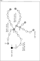
- a reference structure also referred to as a prediction tree
- which point's geometry data is referred to when deriving the predicted value of the geometry data of each point is formed.
- circles indicate points and arrows indicate reference relationships.
- the method of forming this reference structure is arbitrary. For example, it is formed so that the geometry data of nearby points is referenced.
- point 11 (Root vertex) that does not refer to the geometry data of another point
- point 12 (Branch vertex with one child) that is referenced from another point
- point 13 (Branch vertex with 3 children) referenced
- point 14 (Branch vertex with 2 children) referenced by the other two points
- a point 15 (Leaf vertex) not referenced by the other points are formed.
- the predicted value of the geometry data at each point is derived according to such a reference structure (prediction tree). For example, predicted values are derived by four methods (4 modes), and the optimum predicted value is selected from them.
- the point 24 is set as a processing target point (Target point pi) and a predicted value of the geometry data is derived.
- the point 23 (P parent ) to which the point 24 refers to (also referred to as the parent node) in such a reference structure is set as the predicted point 31 of the point 24, and the geometry data thereof is the geometry of the point 24.
- the geometry data of the prediction point 31 (that is, the prediction value of the geometry data of the point 24 in the first mode) is referred to as q (Delta).
- the inverse of the reference vector (arrow between the point 23 and the point 22) starting from the point 23 and ending at the point 22 (P grandparent) which is the parent node of the point 23.
- the start point of the vector is the point 23
- the end point of the inverse vector is the prediction point 32
- the geometry data is the prediction value of the geometry data at the point 24.
- the geometry data of the prediction point 32 (that is, the prediction value of the geometry data of the point 24 in the second mode) is referred to as q (Linear).
- a reference vector (arrow between the point 22 and the point 21) starting from the point 22 and ending at the point 21 (P great-grandparent) which is the parent node of the point 22.
- the start point of the inverse vector of is set to point 23
- the end point of the inverse vector is set to the prediction point 33
- the geometry data is set to the predicted value of the geometry data of point 24.
- the geometry data of the prediction point 33 (that is, the prediction value of the geometry data of the point 24 in the third mode) is referred to as q (Parallelogram).
- the point 24 is set as the root point (Root vertex), and the geometry data of other points is not referred to. That is, for this point 24, the geometry data at point 24 is encoded, not the predicted residuals. In the case of the reference structure of the example of FIG. 2, since the point 24 refers to the point 23, this mode is excluded.
- Predicted residuals are derived for the predicted values of each of the above modes (3 modes in the example of FIG. 2), and the minimum predicted residual is selected. That is, the nearest predicted point with respect to the point 24 is selected, and the predicted residual corresponding to the predicted point is selected.
- the predicted residual of each point is derived. Then, the predicted residual is encoded. By doing so, it is possible to suppress an increase in the amount of code.
- the reference structure (prediction tree) is formed based on a predetermined method, but this forming method is arbitrary. For example, assume that each point 41 is captured in the order shown in A of FIG. In FIG. 3, circles indicate points, and the numbers in the circles indicate the capture order. In FIG. 3, only the point 41 whose capture order is 0 is designated by a reference numeral, but all the circles in FIG. 3 are the points 41. That is, in FIG. 3, five points 41 whose capture order is from 0 to 5 are shown.
- a reference structure may be formed so that each point refers to the nearest point (as a parent node), for example, as shown in FIG. 3B.
- Encoding / decoding is performed according to the reference structure, and the child node (the node whose reference destination is the processing target node) is searched using the stack. Therefore, the decoding order in this case is point 41 where the capture order is "0", point 41 where the capture order is "1", point 41 where the capture order is "3", point 41 where the capture order is "4", and capture.
- the order is "5" point 41, and the capture order is "2" point 41.
- a reference structure may be formed so that each point refers to a point in the previous capture order (referred to as a parent node).
- the decoding order in this case is the same as the capture order.
- the bit rate of the coded data of the geometry data generated by the coding can be controlled. That is, it is possible to control the storage capacity when storing the coded data and the transmission rate when transmitting the coded data.
- the resolution also referred to as spatial resolution
- Such a decoding method is also referred to as scalable decoding (or decoding scalability). By realizing such scalable decoding, it is possible to omit the decoding process of unnecessary data, so that it is possible to suppress an increase in the load of the decoding process.
- the number of points can be reduced during transcoding, which is a process of decoding the coded data of geometry data, changing desired parameters, and re-encoding. By doing so, it is possible to suppress an increase in the transcoding load.
- the bit rate of the coded data of the geometry data generated by transcoding can be controlled.
- the predicted value of the node below that child node cannot be derived. That is, it is not possible to delete only the desired points regardless of this prediction tree (the points of the child nodes are also deleted). Therefore, when a certain point is deleted, a phenomenon may occur in which many points around the point are also deleted according to the structure of the prediction tree. In that case, for example, the distribution mode of the points changes significantly locally, and the shape of the object indicated by the point cloud is deformed (that is, the point cloud cannot correctly express the shape of the object). Was likely to occur.
- ⁇ Hierarchy of reference structure> Therefore, as shown in the top row of the table shown in FIG. 4, the predictive geometry coding is extended and shown in the second row from the top of the table shown in FIG. 4 (column "1").
- a group of points is formed, and a reference structure having the group as a hierarchy is formed.
- this hierarchy is referred to as a group hierarchy, and such a hierarchy of reference structures is referred to as a group hierarchy.
- a reference structure of geometry data in the coding of the point cloud which is layered by a group that classifies the points of the point cloud that expresses a three-dimensional object as a set of points, is formed, and the formed reference structure is formed.
- the predicted value of the geometry data is derived for each point, the predicted residual which is the difference between the geometry data and the predicted value is derived, and the predicted residual of the geometry data of the derived point is encoded. do.
- a reference structure of geometry data in the coding of the point cloud is formed, which is layered by a group that classifies the points of the point cloud that expresses a three-dimensional object as a set of points.
- the predicted value of the geometry data is derived for each point, and the predicted residual which is the difference between the geometry data and the predicted value is derived. It is provided with a predicted residual derivation unit and a coding unit that encodes the predicted residual of the geometry data of each point derived by the predicted residual derivation unit.
- the selection of points for each group hierarchy is in line with the prediction tree.
- points belonging to the lowest layer of this group hierarchy correspond to the node on the most leaf side (Leaf side) of the prediction tree, and points belonging to other group hierarchies are on the root side (Root side) of that node.
- the points belonging to the lower group hierarchy can be deleted without affecting the points belonging to the upper group hierarchy.
- the bit rate of the coded data of the geometry data generated by the coding can be controlled.
- each captured point is grouped and the group is grouped. You may sort (sort) each point in order.
- a reference structure layered by the group is formed. You may.
- a reference structure forming unit has a grouping processing unit that divides points into groups, a sorting unit that sorts the points by group, and each point in the order in which the points are sorted by the sorting unit.
- the group layered reference structure forming unit may be provided to form the reference structure layered by the group.
- These points 51 are grouped by a predetermined method. This grouping method is arbitrary. In the case of A in FIG. 5, the group is divided into a group of points 51 having an odd capture order (1, 3, 5, 7) and a group of points 51 having an even capture order (2, 4, 6, 8). There is.
- these points 51 are sorted by group.
- the point 51 is in the order of the point 51 group having an odd capture order (1, 3, 5, 7) and the point 51 group having an even capture order (2, 4, 6, 8). Are sorted.
- the reference destination of each point is obtained in this sorted order, and a prediction tree is formed.
- a prediction tree is formed.
- the node corresponding to the point 51 whose capture order is even is formed as a node on the leaf side (child node side) of the node corresponding to the point 51 whose capture order is odd. Therefore, even if the points 51 whose capture order is even are deleted, the points 51 whose capture order is odd are not affected.
- the points to be coded can be selected, so that the increase in the load of the coding process can be suppressed.
- the bit rate of the coded data of the geometry data generated by the coding can be controlled.
- the prediction tree By forming the prediction tree by such a method, after sorting, the prediction tree can be formed by the same method as that described in Non-Patent Document 2. Therefore, the prediction tree can be group-hierarchized more easily. As a result, it is possible to suppress an increase in the cost for forming the prediction tree.
- grouping As shown in the fourth column from the top of the table shown in FIG. 4 (column of "1-1-1"), grouping (grouping of points) is performed according to the position of the points. You may.
- the points belonging to each group may be grouped so that the density in the three-dimensional space is uniform (so that the points are spaced apart from each other).
- the number of points can be reduced so that the density of the encoded points becomes uniform. That is, it is necessary to suppress an increase in the load of the coding process or control the bit rate of the coded data so as to reduce the change in the distribution mode of the point cloud (that is, the shape of the object indicated by the point cloud). Can be done.
- the resolution (spatial resolution) on the three-dimensional space of the point cloud can be controlled by increasing or decreasing the number of group hierarchies in which points are deleted.
- grouping is performed according to the characteristics of the points. You may.
- the characteristics of the points used for this grouping are arbitrary. For example, it may be grouped by points corresponding to the edges and corners of the point cloud, or may be grouped by points corresponding to the flat part of the point cloud. Of course, the features may be other than these examples.
- points that have a relatively small subjective effect (characteristic) during reproduction are deleted, and points that have a relatively large subjective effect (characteristic) during reproduction are deleted.
- the grouping method is arbitrary and is not limited to these examples. For example, grouping may be performed according to both the position and characteristics of the points.
- layer information which is information about the group hierarchy may be signaled.
- layer information indicating the group hierarchy may be generated and encoded for each point.
- the reference structure forming unit further includes a layer information generating unit that generates layer information indicating a group hierarchy that is a hierarchy of groups in the reference structure for each point, and the coding unit further includes the layer information.
- the layer information generated by the generator may be further encoded.
- the group hierarchy may be indicated by the difference (relative value from the parent node) from the group hierarchy of the parent node.
- points 60 to 69 are captured as shown in A in FIG. Then, points 60, 63, 66, and 69 are divided into the first group, points 61, 64, and 67 are divided into the second group, and points 62, 65, and 68 are divided. Is divided into a third group. Then, it is assumed that these points are sorted for each group as described above, reference destinations are set, and a prediction tree as shown in B of FIG. 6 is formed.
- the point 61 belongs to the second group, and the parent node of the node corresponding to the point 61 in the prediction tree is the node corresponding to the point 60 belonging to the first group, so it corresponds to the point 61.
- "+1" is generated as layer information for the node to be used. This "+1" indicates that the node to be processed belongs to the group hierarchy (second group) one hierarchy lower than the group hierarchy (first group) of the parent node.
- the point 62 belongs to the third group and the parent node of the node corresponding to the point 62 in the prediction tree is the node corresponding to the point 61 belonging to the second group, the node corresponding to the point 62. For, "+1" is generated as layer information.
- the point 63 belongs to the first group, and the parent node of the node corresponding to the point 63 in the prediction tree is the node corresponding to the point 60 belonging to the same first group. For the corresponding node, "+0" is generated as layer information.
- the point 64 belongs to the second group, and the parent node of the node corresponding to the point 64 in the prediction tree is the node corresponding to the point 61 belonging to the same second group, so that the point 64 corresponds to the point 64. For the node, "+0" is generated as layer information.
- the point 65 belongs to the third group, and the parent node of the node corresponding to the point 65 in the prediction tree is the node corresponding to the point 62 belonging to the same third group, so that the point 65 corresponds to the point 65.
- "+0" is generated as layer information.
- the point 66 belongs to the first group, and the parent node of the node corresponding to the point 66 in the prediction tree is the node corresponding to the point 63 belonging to the same first group, so that the point 66 corresponds to the point 66.
- "+0" is generated as layer information.
- the point 67 belongs to the second group and the parent node of the node corresponding to the point 67 in the prediction tree is the node corresponding to the point 66 belonging to the first group, the node corresponding to the point 67 Generates "+1" as layer information.
- point 68 belongs to the third group and the parent node of the node corresponding to the point 68 in the prediction tree is the node corresponding to the point 65 belonging to the same third group, the node corresponding to the point 68 Therefore, "+0" is generated as the layer information.
- point 69 belongs to the first group, and the parent node of the node corresponding to the point 69 in the prediction tree is the node corresponding to the point 66 belonging to the same first group, so that it corresponds to the point 669. For the node, "+0" is generated as layer information.
- the group hierarchy of each point can be easily grasped on the decoding side based on the signaled layer information. Therefore, at the time of decoding, only the coded data of the desired group hierarchy can be decoded based on the layer information. That is, scalable decoding can be easily realized. In other words, since the decoding side can grasp the structure of the group hierarchy based on the layer information, the coding side can arbitrarily set the group.
- the group hierarchy to which the processing target node belongs as a relative value from the group hierarchy to which the parent node belongs as described above, it is possible to suppress an increase in the code amount due to this layer information.
- the layer information is signaled at the parent node as shown in the seventh stage from the top (stage of "1-2-1") in the table shown in FIG. You may try to do it.
- layer information indicating the group hierarchy of each child node belonging to the processing target node in the reference structure as a relative value to the group hierarchy of the processing target node may be generated and encoded.
- information indicating the group hierarchy of the child node is signaled.
- the layer information may be signaled at the child node.
- the layer information indicating the group hierarchy of the processing target node in the reference structure as a relative value to the group hierarchy of the parent node to which the processing target node belongs may be generated and encoded.
- information (+1) indicating the group hierarchy to which the node corresponding to the point 61 belongs is signaled as the layer information of the node corresponding to the point 61.
- information (+0) indicating the group hierarchy to which the node corresponding to the point 63 belongs is signaled.
- information indicating the group hierarchy of the node is signaled.
- Quantization may be performed when encoding various information such as geometry data (predicted residual).
- the quantization step may be controlled layer by layer as shown in the ninth stage (“1-3” stage) from the top of the table shown in FIG. That is, the predicted residual or the like may be quantized and encoded by a quantization step set for each group hierarchy, which is a hierarchy of groups in the reference structure. For example, the quantization step may be changed for each layer.
- the layer information may be signaled in the child node.
- the quantization step may be signaled. That is, the information indicating the quantization step may be encoded.
- FIG. 4 As shown in the eleventh stage (stage "1-4") from the top of the table shown in FIG. 4, when encoding various information such as geometry data (predicted residual), FIG. 4 As shown in the twelfth column (column of "1-4-1") from the top of the table shown in (1), arithmetic coding may be performed independently for each layer (group hierarchy). That is, the predicted residuals and the like may be arithmetically coded separately for each group hierarchy, which is a hierarchy of groups in the reference structure. By doing so, the coded data can be decoded for each group hierarchy. For example, when a part of the group hierarchy is deleted and transcoded, the transcoding can be performed only by selecting the coded data of the group hierarchy that is not deleted (without decoding). This makes it possible to suppress an increase in the transcoding load. In this case, the layer information may be signaled at the parent node.
- arithmetic coding may be performed independently in units smaller than the group hierarchy. For example, arithmetic coding may be performed independently for each branch or node of the prediction tree.
- the predicted residuals and the like may be arithmetically coded without being divided into group hierarchies, which are hierarchies by groups in the reference structure.
- arithmetic coding may be performed without dividing the predicted residuals of a plurality of group hierarchies.
- arithmetic coding may be performed without dividing the predicted residuals of all group hierarchies.
- whether or not to encode may be selected for each group hierarchy, and the predicted residuals of the group hierarchy selected to be encoded may be encoded. That is, control of whether or not to encode (control of whether or not to delete) may be performed for each group hierarchy.
- the coding control may be performed in units smaller than the group hierarchy. For example, whether or not to encode may be selected for each branch of the reference structure, and the predicted residuals of the nodes belonging to the branches selected to be encoded may be encoded. That is, control of whether or not to encode (control of whether or not to delete) may be performed for each branch. By doing so, the information of some branches in the group hierarchy can be deleted, and finer coding control can be realized.
- the information unit of this coding control is arbitrary, and of course, the coding control may be performed for each information unit other than the above-mentioned example. For example, it may be possible to perform coding control for each of a plurality of information units. For example, it may be possible to perform coding control for each group hierarchy or for each branch.
- FIG. 7 is a block diagram showing an example of a configuration of a coding device, which is an aspect of an information processing device to which the present technology is applied.
- the coding device 100 shown in FIG. 7 is a device that encodes a point cloud (3D data).
- the coding device 100 encodes the point cloud by applying the above-mentioned technology with reference to, for example, FIG.
- FIG. 7 shows the main things such as the processing unit and the data flow, and not all of them are shown in FIG. 7. That is, in the coding apparatus 100, there may be a processing unit that is not shown as a block in FIG. 7, or there may be a processing or data flow that is not shown as an arrow or the like in FIG. 7.
- the coding device 100 has a geometry data coding unit 111 and an attribute data coding unit 112.
- the geometry data coding unit 111 acquires the point cloud (3D data) input to the coding device 100, encodes the geometry data (position information), generates the coded data of the geometry data, and generates it.
- the coded data of the geometry data and the attribute data (attribute information) are supplied to the attribute data coding unit 112.
- the attribute data coding unit 112 acquires the coding data and the attribute data of the geometry data supplied from the geometry data coding unit 111, encodes the attribute data using them, and encodes the attribute data. Is generated, and the coded data of the geometry data and the coded data of the generated attribute data are output to the outside of the coding device 100 (for example, the decoding side) as the coded data of the point cloud data.
- each processing unit may be configured by a logic circuit that realizes the above-mentioned processing.
- each processing unit has, for example, a CPU (Central Processing Unit), a ROM (Read Only Memory), a RAM (Random Access Memory), and the like, and the above-mentioned processing is realized by executing a program using them. You may do so.
- each processing unit may have both configurations, and a part of the above-mentioned processing may be realized by a logic circuit, and the other may be realized by executing a program.
- the configurations of the respective processing units may be independent of each other.
- some processing units realize a part of the above-mentioned processing by a logic circuit, and some other processing units execute a program.
- the above processing may be realized, and another processing unit may realize the above-mentioned processing by both the logic circuit and the execution of the program.
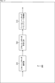
- FIG. 8 is a block diagram showing a main configuration example of the geometry data coding unit 111. It should be noted that FIG. 8 shows the main things such as the processing unit and the flow of data, and not all of them are shown in FIG. That is, in the geometry data coding unit 111, there may be a processing unit that is not shown as a block in FIG. 8, or there may be a processing or data flow that is not shown as an arrow or the like in FIG.
- the geometry data coding unit 111 includes a reference structure forming unit 131, a stack 132, a prediction mode determination unit 133, a coding unit 134, and a prediction point generation unit 135.
- the geometry data of the point cloud data supplied to the geometry data coding unit 111 is supplied to the reference structure forming unit 131.
- the attribute data is not processed by the geometry data coding unit 111, but is supplied to the attribute data coding unit 112.
- the reference structure forming unit 131 generates a reference structure (prediction tree) in point cloud coding for the supplied geometry data. At that time, the reference structure forming unit 131 may form a group-layered reference structure by applying various methods as described above with reference to the table of FIG. Further, the reference structure forming unit 131 generates layer information indicating the formed reference structure for each point. The reference structure forming unit 131 supplies the geometry data, layer information, and the like of the processing target point to the stack 132 according to the formed reference structure. At that time, the reference structure forming unit 131 may apply various methods as described above with reference to the table of FIG.
- the reference structure forming unit 131 determines whether or not to encode the child node in the reference structure (prediction tree) formed by the reference structure forming unit 131 according to the coding control by the user or the like, and encodes the child node. If it is determined to be so, the geometry data, layer information, and the like of the child nodes of the processing target node may be supplied to the stack 132. For example, the reference structure forming unit 131 may select whether or not to encode the predicted residual or the like for each group hierarchy, and supply the predicted residual or the like of the nodes belonging to the group hierarchy to the stack 132.
- the reference structure forming unit 131 may select whether or not to encode the predicted residual or the like for each branch of the reference structure, and supply the predicted residual or the like of the node belonging to the branch to the stack 132. By doing so, the geometry data can be encoded only for some points.
- the stack 132 holds information in a last-in, first-out manner.
- the stack 132 holds the geometry data, layer information, and the like of each point supplied from the reference structure forming unit 131. Further, the stack 132 supplies the last held information among the held information to the prediction mode determination unit 133 in response to the request from the prediction mode determination unit 133.
- the prediction mode determination unit 133 performs processing related to determination of the prediction mode (prediction point). For example, the prediction mode determination unit 133 acquires the geometry data, layer information, and the like of the point last held in the stack 132. Further, the prediction mode determination unit 133 acquires the geometry data and the like of the prediction point of the point from the prediction point generation unit 135. When there are a plurality of prediction points corresponding to the processing target points as in the example of FIG. 2, all of them are acquired. Then, the prediction mode determination unit 133 determines the prediction point (that is, the prediction mode) to be applied. At that time, the prediction mode determination unit 133 may apply various methods as described above with reference to the table of FIG.
- the prediction mode determination unit 133 derives a prediction residual, which is the difference between the geometry data (prediction value) and the geometry data of the processing target point, for each prediction point, and compares the values. By such comparison, the prediction mode (prediction method) to be applied is selected. For example, the predicted point closest to the processing target point is selected.
- the prediction mode determination unit 133 supplies information about each point (for example, prediction residuals of the selected prediction mode, layer information, etc.) to the coding unit 134.
- the coding unit 134 acquires the information supplied by the prediction mode determination unit 133 (for example, the prediction residual of the selected prediction mode, the layer information, etc.), encodes it, and generates the coded data.
- the prediction mode determination unit 133 for example, the prediction residual of the selected prediction mode, the layer information, etc.
- the coding unit 134 may apply various methods as described above with reference to the table of FIG.
- the coding unit 134 can be quantized and coded in a quantization step set for each group hierarchy.
- the coding unit 134 can encode and signal the information indicating the quantization step.
- the coding unit 134 can perform arithmetic coding by dividing the predicted residuals and the like into each group hierarchy, or can perform arithmetic coding without dividing into each group hierarchy.
- the coding unit 134 supplies the generated coding data to the attribute data coding unit 112 as the coding data of the geometry data. Further, the coding unit 134 supplies information such as geometry data of the processing target point to the prediction point generation unit 135.
- the prediction point generation unit 135 performs processing related to generation of prediction points, that is, derivation of prediction values. For example, the prediction point generation unit 135 acquires information such as geometry data of the processing target point supplied from the coding unit 134. Further, the prediction point generation unit 135 derives the geometry data of the prediction point that can be generated using the geometry data of the processing target point (for example, the prediction value of the geometry data of the child node of the processing target node). At that time, the prediction point generation unit 135 may apply various methods as described above with reference to the table of FIG. The prediction point generation unit 135 supplies the derived predicted value to the prediction mode determination unit 133 as needed.
- FIG. 9 is a block diagram showing a main configuration example of the reference structure forming unit 131. It should be noted that FIG. 9 shows the main things such as the processing unit and the flow of data, and not all of them are shown in FIG. That is, in the reference structure forming unit 131, there may be a processing unit that is not shown as a block in FIG. 9, or there may be a processing or data flow that is not shown as an arrow or the like in FIG.
- the reference structure forming unit 131 includes a grouping processing unit 151, a sorting unit 152, a group layered reference structure forming unit 153, and a layer information generation unit 154.
- the grouping processing unit 151 performs processing related to grouping. For example, the grouping processing unit 151 groups the points of the geometry data supplied to the reference structure forming unit 131. At that time, the grouping processing unit 151 may apply various methods as described above with reference to the table of FIG. For example, the grouping processing unit 151 may perform grouping according to the position of the point. Further, the grouping processing unit 151 may perform the grouping according to the characteristics of the points. The grouping processing unit 151 supplies the geometry data of each grouped point to the sorting unit 152.
- the sort unit 152 performs processing related to sorting points. For example, the sort unit 152 acquires the geometry data of each grouped point supplied by the grouping processing unit 151. Then, the sort unit 152 sorts the geometry data at each point. At that time, the sort unit 152 may apply various methods as described above with reference to the table of FIG. For example, the sorting unit 152 sorts the geometry data of each point grouped by the grouping processing unit 151 so as to be grouped into each group. The sort unit 152 supplies the geometry data of each sorted point to the group layered reference structure forming unit 153.
- the group layered reference structure forming unit 153 performs processing related to the formation of the reference structure. For example, the group layered reference structure forming unit 153 acquires the geometry data of each sorted point supplied from the sorting unit 152. The group layered reference structure forming unit 153 forms a reference structure. At that time, the group layered reference structure forming unit 153 may apply various methods as described above with reference to the table of FIG. For example, the group layered reference structure forming unit 153 forms a group layered reference structure by setting the reference destination of each point according to the sorted order supplied from the sort unit 152. The method of forming this reference structure is arbitrary. The group layered reference structure forming unit 153 supplies the reference structure thus formed to the layer information generation unit 154.
- the layer information generation unit 154 acquires the reference structure supplied from the group layered reference structure forming unit 153.
- the layer information generation unit 154 generates layer information indicating the reference structure thereof.
- the layer information generation unit 154 may apply various methods as described above with reference to the table of FIG.
- the layer information generation unit 154 generates information indicating the group hierarchy of each child node belonging to the processing target node in the reference structure (for example, a value relative to the group hierarchy of the processing target node) as the layer information of the processing target node. , May be signaled.
- the layer information generation unit 154 generates information indicating the group hierarchy of the processing target node in the reference structure (for example, a relative value with the group hierarchy of the parent node to which the processing target node belongs) as the layer information of the processing target node. It may be signaled.
- the layer information generation unit 154 supplies the generated layer information to the stack 132 (FIG. 8).
- the coding device 100 can make the reference structure of the geometry data into a group hierarchy. Therefore, as described above, the coding apparatus 100 can suppress an increase in the load of the coding process. In addition, the bit rate of the coded data of the geometry data generated by the coding can be controlled. In addition, it is possible to control the storage capacity when storing the coded data and the transmission rate when transmitting the coded data.
- the coding device 100 encodes the data in the point cloud by executing the coding process. An example of the flow of this coding process will be described with reference to the flowchart of FIG.
- the geometry data coding unit 111 of the coding apparatus 100 encodes the input point cloud geometry data by executing the geometry data coding process in step S101, and the geometry Data encoding Generate data.
- step S102 the attribute data coding unit 112 encodes the input point cloud attribute data and generates the coded data of the attribute data.
- step S102 When the process of step S102 is completed, the coding process is completed.
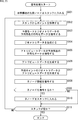
- the reference structure forming unit 131 executes the reference structure forming process in step S131 to form the reference structure (prediction tree) of the geometry data.
- the reference structure forming unit 131 also generates layer information corresponding to the formed reference structure.
- step S132 the reference structure forming unit 131 stores the geometry data and the like of the head node of the reference structure formed in step S131 in the stack 132.
- step S133 the prediction mode determination unit 133 acquires the geometry data of the last stored point (node) from the stack 132.
- step S134 the prediction mode determination unit 133 sets the point for which information was acquired in step S133 as the processing target, derives the prediction residual of the geometry data for the processing target point, and determines the prediction mode.
- step S135 the coding unit 134 encodes the prediction mode determined in step S134. Further, in step S136, the coding unit 134 encodes the prediction residual of the geometry data in the prediction mode determined in step S134. Further, in step S137, the coding unit 134 encodes the child node information indicating whether the child node of the processing target node is a degree node. Further, in step S138, the coding unit 134 encodes the layer information generated in step S131. The coding unit 134 supplies the coding data of these information to the attribute data coding unit 112 as the coding data of the geometry data.
- step S139 the reference structure forming unit 131 determines whether or not to encode the child node of the processing target node based on the coding control by the user or the like. If it is determined to be encoded, the process proceeds to step S140.
- step S140 the reference structure forming unit 131 stores the geometry data and the like of its child nodes in the stack 132.
- the process of step S140 proceeds to step S141. If it is determined in step S139 that the child node is not encoded, the process of step S140 is skipped and the process proceeds to step S141.
- step S141 the prediction point generation unit 135 generates the geometry data of the prediction point that can be generated using the geometry data of the processing target point.
- step S142 the prediction mode determination unit 133 determines whether or not the stack 132 is empty. If it is determined that the stack 132 is not empty (that is, the information of at least one point is stored), the process returns to step S133. That is, the processing of steps S133 to S142 is executed with the point finally stored in the stack 132 as the processing target.
- step S142 the geometry data coding process is completed and the process returns to FIG.
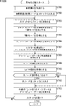
- the grouping process unit 151 groups each point of the point cloud in step S161.
- step S162 the sort unit 152 sorts the processing order of each point of the point cloud so as to line up for each group set in step S161.
- step S163 the group layered reference structure forming unit 153 forms a group layered reference structure by forming reference destinations for each point in the order sorted in step S163.
- step S164 the layer information generation unit 154 forms the layer information of each point.
- step S164 When the process of step S164 is completed, the reference structure forming process is completed, and the process returns to FIG.
- the coding apparatus 100 can group-layer the reference structure of the geometry data. Therefore, as described above, the coding apparatus 100 can suppress an increase in the load of the coding process. In addition, the bit rate of the coded data of the geometry data generated by the coding can be controlled. In addition, it is possible to control the storage capacity when storing the coded data and the transmission rate when transmitting the coded data.
- FIG. 13 is a block diagram showing an example of a configuration of a decoding device, which is an aspect of an information processing device to which the present technology is applied.
- the decoding device 200 shown in FIG. 13 is a device that decodes the coded data of the point cloud (3D data).
- the decoding device 200 decodes, for example, the coded data of the point cloud generated in the coding device 100.
- FIG. 13 shows the main things such as the processing unit and the flow of data, and not all of them are shown in FIG. That is, in the decoding device 200, there may be a processing unit that is not shown as a block in FIG. 13, or there may be a processing or data flow that is not shown as an arrow or the like in FIG.
- the decoding device 200 has a geometry data decoding unit 211 and an attribute data decoding unit 212.
- the geometry data decoding unit 211 acquires the coded data of the point cloud (3D data) input to the coding device 100, decodes the coded data of the geometry data, generates the geometry data, and generates the generated geometry.
- the data and the coded data of the attribute data are supplied to the attribute data decoding unit 212.
- the attribute data decoding unit 212 acquires the geometry data supplied from the geometry data decoding unit 211 and the coded data of the attribute data. Further, the attribute data decoding unit 212 decodes the coded data of the attribute data using the geometry data to generate the attribute data, and the geometry data and the generated attribute data are used as point cloud data in the decoding device 200. Output to the outside.
- each processing unit may be configured by a logic circuit that realizes the above-mentioned processing.
- each processing unit may have, for example, a CPU, ROM, RAM, etc., and execute a program using them to realize the above-mentioned processing.
- each processing unit may have both configurations, and a part of the above-mentioned processing may be realized by a logic circuit, and the other may be realized by executing a program.
- the configurations of the respective processing units may be independent of each other.
- some processing units realize a part of the above-mentioned processing by a logic circuit, and some other processing units execute a program.
- the above processing may be realized, and another processing unit may realize the above-mentioned processing by both the logic circuit and the execution of the program.
- FIG. 14 is a block diagram showing a main configuration example of the geometry data decoding unit 211. It should be noted that FIG. 14 shows the main things such as the processing unit and the flow of data, and not all of them are shown in FIG. That is, in the geometry data decoding unit 211, there may be a processing unit that is not shown as a block in FIG. 14, or there may be a processing or data flow that is not shown as an arrow or the like in FIG.
- the geometry data decoding unit 211 has a storage unit 231, a stack 232, a decoding unit 233, a geometry data generation unit 234, and a prediction point generation unit 235.
- the coded data of the geometry data supplied to the geometry data decoding unit 211 is supplied to the storage unit 231.
- the coded data of the attribute data is not processed by the geometry data decoding unit 211, but is supplied to the attribute data decoding unit 212.
- the storage unit 231 stores the encoded data of the geometry data supplied to the geometry data decoding unit 211. Further, the storage unit 231 supplies the coded data of the geometry data of the point to be decoded to the stack 232 under the control of the decoding unit 233. At that time, the storage unit 231 may apply various methods as described above with reference to the table of FIG.
- Stack 232 holds information in a last-in, first-out manner. For example, the stack 232 holds the coded data of each point supplied from the storage unit 231. Further, the stack 232 supplies the last held information among the held information to the decoding unit 233 in response to the request from the decoding unit 233.
- the decoding unit 233 performs processing related to decoding the coded data of the geometry data. For example, the decoding unit 233 acquires the coded data of the point last held in the stack 232. Further, the decoding unit 233 decodes the acquired coded data and generates geometry data (predicted residual, etc.). At that time, the decoding unit 233 may apply various methods as described above with reference to the table of FIG. The decoding unit 233 supplies the generated geometry data (predicted residuals, etc.) to the geometry data generation unit 234.
- the decoding unit 233 can perform decoding control so as to decode only a part of the coded data requested by, for example, a user or the like. For example, the decoding unit 233 can control whether or not to decode for each group hierarchy. Further, the decoding unit 233 can control whether or not to decode each branch of the reference structure. Then, the decoding unit 233 can control the storage unit 231 and store only the coded data of the point to be decoded in the stack 232. With such decoding control, the decoding unit 233 can realize scalable decoding of geometry data.
- the decoding unit 233 is hierarchized by the group in the reference structure of the geometry data in the coding of the point cloud, which is hierarchized by the group that classifies the points of the point cloud that expresses the object of the three-dimensional shape as a set of points.
- the coded data corresponding to the hierarchy may be decoded.
- Geometry data generation unit 234 performs processing related to geometry data generation. For example, the geometry data generation unit 234 acquires information such as a predicted residual supplied from the decoding unit 233. Further, the geometry data generation unit 234 acquires a prediction point corresponding to the processing target point (that is, a predicted value of the geometry data of the processing target point) from the prediction point generation unit 235. Then, the geometry data generation unit 234 generates the geometry data of the processing target point by using the acquired predicted residual and the predicted value (for example, adding both). The geometry data generation unit 234 supplies the generated geometry data to the attribute data decoding unit 212.
- the geometry data generation unit 234 acquires information such as a predicted residual supplied from the decoding unit 233. Further, the geometry data generation unit 234 acquires a prediction point corresponding to the processing target point (that is, a predicted value of the geometry data of the processing target point) from the prediction point generation unit 235. Then, the geometry data generation unit 234 generates the geometry data of the processing target point by using the acquired predicted residual
- the prediction point generation unit 235 performs processing related to generation of prediction points, that is, derivation of prediction values. For example, the prediction point generation unit 235 acquires information such as geometry data of the processing target point generated by the geometry data generation unit 234. Further, the prediction point generation unit 235 derives the geometry data of the prediction point that can be generated using the geometry data of the processing target point (for example, the prediction value of the geometry data of the child node of the processing target node). At that time, the prediction point generation unit 235 may apply various methods as described above with reference to the table of FIG. For example, the prediction point generation unit 235 can generate prediction points in the same manner as in the case of the prediction point generation unit 135 of the coding device 100. The prediction point generation unit 235 supplies the derived predicted value to the geometry data generation unit 234 as needed.
- the decoding device 200 can decode the coded data using the grouped reference structure of the geometry data. Therefore, as described above, the decoding device 200 can realize scalable decoding and suppress an increase in the load of the decoding process.
- the decoding device 200 decodes the coded data of the point cloud by executing the decoding process.
- An example of the flow of the decoding process will be described with reference to the flowchart of FIG.
- the geometry data decoding unit 211 of the decoding device 200 decodes the input coded data of the input point cloud geometry data by executing the geometry data decoding process in step S201, and the geometry is decoded. Generate data.
- step S202 the attribute data decoding unit 212 encodes the coded data of the input point cloud attribute data and generates the attribute data.
- step S202 When the process of step S202 is completed, the decryption process is completed.
- the storage unit 231 stores the coded data of the supplied geometry data, and in step S231, the coded data of the first node of the reference structure (prediction tree) of the geometry data. Is stored in the stack 232.
- step S232 the decoding unit 233 acquires the coded data of the last stored point (node) from the stack 232.
- step S233 the decoding unit 233 decodes the coded data acquired in step S232 and generates layer information. Further, in step S234, the decoding unit 233 decodes the coded data acquired in step S232 and generates a prediction residual of the prediction mode and the geometry data.
- step S235 the geometry data generation unit 234 generates geometry data of the processing target node using the predicted residual generated in step S234 and the predicted value of the processing target node (for example, adding both). ..
- step S236 the prediction point generation unit 235 generates geometry data (that is, prediction value) of prediction points that can be generated using the geometry data of the processing target node.
- step S237 the decoding unit 233 decodes the coded data acquired in step S232 and generates child node information.
- step S238 the decoding unit 233 determines whether or not the child node is also decoded based on the child node information, the layer information, and the like according to the decoding control of the user or the like. If it is determined that the child node is also decoded, the process proceeds to step S239.
- step S239 the decoding unit 233 controls the storage unit 231 and stores the coded data of its child node in the stack 232.
- step S240 the process of step S239 is skipped and the process proceeds to step S240.
- step S240 the decoding unit 233 determines whether or not the stack 232 is empty. If it is determined that the stack 232 is not empty (that is, the information of at least one point is stored), the process returns to step S232. That is, the process of step S232 x to step S240 is executed with the point finally stored in the stack 232 as the processing target.
- step S240 the geometry data decoding process is completed and the process returns to FIG.
- the decoding device 200 can decode the coded data using the grouped reference structure of the geometry data. Therefore, as described above, the decoding device 200 can realize scalable decoding and suppress an increase in the load of the decoding process.
- FIG. 17 is a block diagram showing an example of a configuration of a transcoder, which is one aspect of an information processing apparatus to which the present technology is applied.
- the transcoder 300 shown in FIG. 17 is a device that decodes the coded data of the point cloud (3D data) and re-codes it by performing, for example, parameter conversion.
- the transcoder 300 transcodes (decodes / encodes) the coded data of the point cloud generated in the coding device 100, for example.
- FIG. 17 shows the main things such as the processing unit and the data flow, and not all of them are shown in FIG. That is, in the transcoder 300, there may be a processing unit that is not shown as a block in FIG. 17, or there may be a processing or data flow that is not shown as an arrow or the like in FIG.
- the transcoder 300 has a geometry data decoding unit 311, a geometry data coding unit 312, and an attribute data transcoding unit 313.
- the geometry data decoding unit 311 acquires the coded data of the point cloud data input to the transcoder 300.
- the geometry data decoding unit 311 decodes the coded data and generates the geometry data.
- the geometry data decoding unit 311 may apply various methods as described above with reference to the table of FIG.
- the geometry data decoding unit 311 may have the same configuration as the geometry data decoding unit 211 of the decoding device 200, and may perform the same processing. That is, the geometry data decoding unit 311 may realize scalable decoding.
- the geometry data decoding unit 311 supplies the coded data of the attribute data and the generated geometry data to the geometry data coding unit 312.
- the geometry data coding unit 312 acquires the coded data and the geometry data of the attribute data supplied from the geometry data decoding unit 311.
- the geometry data coding unit 312 re-encodes the geometry data and generates the coded data of the geometry data.
- the geometry data coding unit 312 may apply various methods as described above with reference to the table of FIG.
- the geometry data coding unit 312 may have the same configuration as the geometry data coding unit 111 of the coding device 100, and may perform the same processing. That is, the geometry data coding unit 312 may group-layer the reference structure of the geometry data. Further, after the reference structure is determined, the geometry data coding unit 312 can reduce the number of points and perform coding.
- the geometry data coding unit 312 may be able to control the bit rate of the coded data to be generated.
- the geometry data coding unit 312 supplies the coded data of the attribute data and the coded data of the generated geometry data to the attribute data transcoding processing unit 313.
- the geometry data parameters such as reduction of the number of points may be changed by the geometry data decoding unit 311 (performed by scalable decoding) or by the geometry data coding unit 312. It may be done in both of them.
- the attribute data transcoding processing unit 313 performs processing related to transcoding of attribute data. For example, the attribute data transcoding processing unit 313 acquires the coded data of the geometry data supplied from the geometry data coding unit 312 and the coded data of the attribute data. Further, the attribute data transcoding processing unit 313 decodes (transcodes) the coded data of the acquired attribute data by a predetermined method. The attribute data transcoding processing unit 313 outputs the coded data of the geometry data and the coded data of the generated attribute data as a transcoding result to the outside of the transcoder 300.
- the transcoder 300 can reduce the number of points during transcoding. That is, the transcoder 300 can suppress an increase in the load of the transcode. Further, the transcoder 300 can control the bit rate of the coded data of the geometry data generated by transcoding.
- each processing unit may be configured by a logic circuit that realizes the above-mentioned processing.
- each processing unit may have, for example, a CPU, ROM, RAM, etc., and execute a program using them to realize the above-mentioned processing.
- each processing unit may have both configurations, and a part of the above-mentioned processing may be realized by a logic circuit, and the other may be realized by executing a program.
- the configurations of the respective processing units may be independent of each other.
- some processing units realize a part of the above-mentioned processing by a logic circuit, and some other processing units execute a program.
- the above processing may be realized, and another processing unit may realize the above-mentioned processing by both the logic circuit and the execution of the program.
- Transcoding process flow Next, the processing executed by the transcoder 300 will be described.
- the transcoder 300 transcodes the coded data of the point cloud by executing the transcoding process. An example of the flow of this transcoding process will be described with reference to the flowchart of FIG.
- the geometry data decoding unit 311 of the transcoder 300 decodes the coded data and generates the geometry data by executing the geometry data decoding process in step S301.
- the geometry data decoding unit 311 can perform this geometry data decoding process in the same flow as the geometry data decoding process described with reference to the flowchart of FIG.
- the geometry data coding unit 312 encodes the geometry data by executing the geometry data coding process, and generates the coded data.
- the geometry data coding unit 312 can perform this geometry data coding process in the same flow as the geometry data coding process described with reference to the flowchart of FIG.
- step S303 the attribute data transcoding processing unit 313 transcodes the attribute data.
- the transcoding process is completed.
- the transcoder 300 can reduce the number of points at the time of transcoding. That is, the transcoder 300 can suppress an increase in the load of the transcode. Further, the transcoder 300 can control the bit rate of the coded data of the geometry data generated by transcoding.
- Second Embodiment> ⁇ Predicted residual coding of attribute data>
- the predictive geometry coding has been extended and shown in the second row from the top of the table shown in FIG. 19 (column "2"). As such, apply predictive geometry coding to the encoding of attribute data.
- a reference structure of attribute data in the encoding of a point cloud that expresses a three-dimensional object as a set of points is formed, and a predicted value of attribute data is derived for each point based on the formed reference structure.
- the predicted residual which is the difference between the attribute data and the predicted value is derived, and the predicted residual of the attribute data of each derived point is encoded.
- a reference structure forming unit that forms a reference structure for attribute data in point cloud coding that expresses a three-dimensional object as a set of points, and a reference structure formed by the reference structure forming unit. Based on, the predicted residual value of the attribute data is derived for each point, and the predicted residual that is the difference between the attribute data and the predicted value is derived. It is provided with a coding unit that encodes the predicted residual of the attribute data of each point.
- the reference structure of the attribute data in that case is 4 from the top of the table shown in FIG.
- the reference structure may be shared between the geometry data and the attribute data.
- the reference structure applied in predictive geometry coding may also be applied to coding of attribute data.
- by sharing the reference structure between the geometry data and the attribute data it is possible to perform scalable decoding of the point cloud data (geometry data and attribute data). Therefore, it is possible to suppress an increase in the load of the decoding process. It also enables lower latency decoding.
- the reference structure may be formed based on the geometry data, the reference structure may be formed based on the attribute data, or the geometry data may be formed.
- the reference structure may be formed based on both the and attribute data.
- the reference structure of all or part of the attribute data is referred to as the reference structure of the geometry data. It may be formed independently.
- the parameters related to the color (RGB) of the attribute data may have a reference structure common to the geometry data, and the parameters such as the reflectance of the attribute data may be formed independently of the reference structure of the geometry data.
- the attribute data of the prediction points of the processing target nodes are obtained from the top of the table shown in FIG. As shown in the 7th stage (stage of "2-2-1"), it may be the same as the attribute data of the parent node of the processing target node.
- the attribute data of the prediction point of the processing target node is used as the parent node of the processing target node. It may be the average of the attribute data of the parent node and the attribute data of its parent node.
- the attribute data of the prediction point of the processing target node is used as the parent node of the processing target node.
- the weighted average of the attribute data of and the attribute data of its parent node may be weighted by the reciprocal of the distance between the points corresponding to those nodes.
- the attribute data of the prediction point of the processing target node is input to the k node in the vicinity of the decoded node. It may be the average of the attribute data of.
- the prediction point that minimizes the prediction residual of the geometry data may be selected.
- the prediction point that minimizes the prediction residual of the attribute data is selected. May be good.
- the evaluation function f is the predicted residual of each variable of the geometry data (x coordinate, y coordinate, z coordinate) and each variable of the attribute data (color, reflectance, etc.).
- the variables in () may be used, and the prediction points may be selected based on the total predicted residuals of those variables.
- diff [variable name] indicates the predicted residual of each variable.
- the prediction mode can be selected by considering not only the position but also each variable of the attribute data, so that the encoding / decoding is adapted to not only the geometry data but also the characteristics of the attribute data. It can be performed. For example, if there are many variables in the attribute data (in many dimensions), or if the range of variables in the attribute data is larger than the variables in the geometry data, the dependency on the variables in the geometry data is reduced (in other words, the attributes). The prediction mode can be selected to improve the dependence of the data on variables).
- FIG. 20 is a block diagram showing an example of a configuration of a coding device, which is an aspect of an information processing device to which the present technology is applied.
- the coding device 400 shown in FIG. 20 is a device that encodes a point cloud (3D data), similarly to the coding device 100.
- the coding device 400 encodes the point cloud by applying the above-mentioned technology with reference to, for example, FIG.
- FIG. 20 shows the main things such as the processing unit and the data flow, and not all of them are shown in FIG. 20. That is, in the coding apparatus 400, there may be a processing unit that is not shown as a block in FIG. 20, or there may be a processing or data flow that is not shown as an arrow or the like in FIG. 20.
- the coding device 400 has a reference structure forming unit 411, a stack 412, a prediction mode determination unit 413, a coding unit 414, and a prediction point generation unit 415.
- the point cloud data (geometry data and attribute data) supplied to the coding device 400 is supplied to the reference structure forming unit 411.
- the reference structure forming unit 411 generates a reference structure (prediction tree) in point cloud coding for both the supplied geometry data and attribute data. At that time, the reference structure forming unit 411 can form the reference structure by applying various methods as described above with reference to the table of FIG. For example, the reference structure forming unit 411 can form a common reference structure between the geometry data and the attribute data. Further, the reference structure forming unit 411 can form the reference structure of the geometry data and the reference structure of the attribute data independently of each other. The reference structure forming unit 411 supplies the geometry data and the attribute data of the processing target point to the stack 412 according to the formed reference structure.
- a reference structure prediction tree
- Stack 412 holds information in a last-in, first-out manner. For example, the stack 412 holds the information of each point supplied from the reference structure forming unit 131. Further, the stack 412 supplies the last held information among the held information to the prediction mode determination unit 413 in response to the request from the prediction mode determination unit 413. The stack 412 can perform these processes for both geometry data and attribute data.
- the prediction mode determination unit 413 performs processing related to determination of the prediction mode (prediction point). For example, the prediction mode determination unit 413 acquires information on the last point held in the stack 412. Further, the prediction mode determination unit 413 acquires information on the prediction point of the point (that is, the prediction value of the processing target point) and the like from the prediction point generation unit 415. When there are a plurality of prediction points corresponding to the processing target points as in the example of FIG. 2, all of them are acquired. Then, the prediction mode determination unit 413 determines the prediction point (that is, the prediction mode) to be applied.
- the prediction mode determination unit 413 can perform such processing for both geometry data and attribute data. Further, the prediction mode determination unit 413 may apply various methods as described above with reference to the table of FIG. 19 during the processing.
- the prediction mode determination unit 413 can select a prediction point (prediction mode) that minimizes the prediction residual of the geometry data. Further, the prediction mode determination unit 413 can select a prediction point (prediction mode) that minimizes the prediction residual of the attribute data. Further, the prediction mode determination unit 413 can select a prediction point (prediction mode) that minimizes the prediction residual of the geometry data and the attribute data.
- the prediction mode determination unit 413 supplies information about each point (for example, the prediction residual of the geometry data and attribute data of the selected prediction mode) to the coding unit 414.
- the coding unit 414 acquires the information supplied by the prediction mode determination unit 413 (for example, the prediction residual of the selected prediction mode, etc.), encodes it, and generates the coded data.
- the coding unit 414 can perform such processing on both the geometry data and the attribute data.
- the coding unit 414 supplies the generated coded data as coded data of geometry data and attribute data to the outside of the coding device 400 (for example, the decoding side). Further, the coding unit 414 supplies the geometry data and the attribute data of the processing target point to the prediction point generation unit 415.
- the prediction point generation unit 415 performs processing related to generation of prediction points, that is, derivation of prediction values. For example, the prediction point generation unit 415 acquires information such as geometry data and attribute data of the processing target point supplied from the coding unit 414. Further, the prediction point generation unit 415 can generate geometry data or attribute data of the prediction point using the geometry data or attribute data of the processing target point (for example, geometry data or attribute data of a child node of the processing target node). Predicted value) is derived. At that time, the prediction point generation unit 415 may apply various methods as described above with reference to the table of FIG. The prediction point generation unit 415 supplies the derived predicted value to the prediction mode determination unit 413 as needed.
- the coding device 400 can encode the attribute data by the same method as the predictive geometry coding. Therefore, the coding device 400 can obtain the same effect as that of the geometry data in coding the attribute data. For example, since the predicted residual is encoded, the coding apparatus 400 can suppress an increase in the code amount of the coded data of the attribute data. In addition, the coding apparatus 400 can control the storage capacity when storing the coded data and the transmission rate when transmitting the coded data. That is, the coding device 400 can control the coding data bit rate of the attribute data.
- each processing unit may be configured by a logic circuit that realizes the above-mentioned processing.
- each processing unit may have, for example, a CPU, ROM, RAM, etc., and execute a program using them to realize the above-mentioned processing.
- each processing unit may have both configurations, and a part of the above-mentioned processing may be realized by a logic circuit, and the other may be realized by executing a program.
- the configurations of the respective processing units may be independent of each other. For example, some processing units realize a part of the above-mentioned processing by a logic circuit, and some other processing units execute a program.
- the above processing may be realized, and another processing unit may realize the above-mentioned processing by both the logic circuit and the execution of the program.
- the coding device 400 encodes the data in the point cloud by executing the coding process. An example of the flow of this coding process will be described with reference to the flowchart of FIG.
- the reference structure forming unit 411 executes the reference structure forming process in step S401 to form a reference structure (prediction tree) of the geometry data and the attribute data.
- the reference structure forming unit 411 can form the reference structure by the same method as that described in Non-Patent Document 2, for example.
- step S402 the reference structure forming unit 411 stores the geometry data, attribute data, etc. of the head node of the reference structure formed in step S401 in the stack 412.
- step S403 the prediction mode determination unit 413 acquires the geometry data, attribute data, etc. of the last stored point (node) from the stack 412.
- step S404 the prediction mode determination unit 413 targets the point for which information was acquired in step S403 as the processing target, derives the prediction residual of the geometry data for the processing target point, and determines the prediction mode.
- step S405 the coding unit 414 encodes the prediction mode determined in step S404. Further, in step S406, the coding unit 414 encodes the prediction residual of the geometry data in the prediction mode determined in step S404.
- step S407 the prediction mode determination unit 413 performs recolor processing and derives the prediction residual of the attribute data.
- the coding unit 414 encodes the predicted residuals of the attribute data.
- step S409 the coding unit 414 encodes the child node information indicating which node the child node of the processing target node is.
- step S410 the reference structure forming unit 411 determines whether or not to encode the child node of the processing target node based on the coding control by the user or the like. If it is determined to be encoded, the process proceeds to step S411.
- step S411 the reference structure forming unit 411 stores the geometry data and the like of its child nodes in the stack 412. When the process of step S411 is completed, the process proceeds to step S412. If it is determined in step S410 that the child node is not encoded, the process of step S411 is skipped and the process proceeds to step S412.
- step S412 the prediction point generation unit 415 generates geometry data and attribute data of prediction points that can be generated using information (geometry data, attribute data, etc.) of the processing target point.
- step S413 the prediction mode determination unit 413 determines whether or not the stack 412 is empty. If it is determined that the stack 412 is not empty (that is, the information of at least one point is stored), the process returns to step S403. That is, each process of step S403 to step S413 is executed with the point finally stored in the stack 412 as the processing target.
- step S413 When such processing is repeated and it is determined in step S413 that the stack is empty, the geometry data coding processing ends.
- the coding apparatus 400 can encode the attribute data by the same method as the predictive geometry coding. Therefore, the coding device 400 can obtain the same effect as that of the geometry data in coding the attribute data. For example, since the predicted residual is encoded, the coding apparatus 400 can suppress an increase in the code amount of the coded data of the attribute data. In addition, the coding apparatus 400 can control the storage capacity when storing the coded data and the transmission rate when transmitting the coded data. That is, the coding device 400 can control the coding data bit rate of the attribute data.
- FIG. 22 is a block diagram showing an example of a configuration of a decoding device, which is an aspect of an information processing device to which the present technology is applied.
- the decoding device 500 shown in FIG. 22 is a device that decodes the coded data of the point cloud (3D data).
- the decoding device 500 decodes, for example, the coded data of the point cloud generated in the coding device 400.
- FIG. 22 shows the main things such as the processing unit and the data flow, and not all of them are shown in FIG. 22. That is, in the decoding device 500, there may be a processing unit that is not shown as a block in FIG. 22, or there may be a processing or data flow that is not shown as an arrow or the like in FIG. 22.
- the decoding device 50 has a storage unit 511, a stack 512, a decoding unit 513, a point data generation unit 514, and a prediction point generation unit 515.
- the encoded data of the geometry data and the attribute data supplied to the decoding device 500 is supplied to the storage unit 511.
- the storage unit 511 stores the encoded data of the geometry data and the attribute data supplied to the decoding device 500. Further, the storage unit 511 supplies the encoded data of the geometry data and the attribute data of the point to be decoded to the stack 512 under the control of the decoding unit 513.
- the stack 512 holds information in a last-in, first-out manner.
- the stack 512 holds the geometry data of each point supplied from the storage unit 511, the coded data of the attribute data, and the like. Further, the stack 512 supplies the last held information (for example, geometry data, coded data of attribute data, etc.) among the held information to the decoding unit 513 in response to the request from the decoding unit 513.
- the decoding unit 513 performs processing related to decoding the coded data for both the geometry data and the attribute data. For example, the decoding unit 513 acquires the coded data of the point last held in the stack 512. Further, the decoding unit 513 decodes the acquired coded data and generates geometry data (predicted residuals and the like) and attribute data (predicted residuals and the like). At that time, the decoding unit 513 may apply various methods as described above with reference to the table of FIG. The decoding unit 513 supplies the generated geometry data (predicted residuals, etc.) and attribute data (predicted residuals, etc.) to the point data generation unit 514.
- the point data generation unit 514 performs processing related to generation of point data (geometry data and attribute data). For example, the point data generation unit 514 acquires information such as a predicted residual supplied from the decoding unit 513. Further, the point data generation unit 514 acquires a prediction point corresponding to the processing target point (that is, a prediction value of the geometry data of the processing target point and a prediction value of the attribute data) from the prediction point generation unit 515. Then, the point data generation unit 514 generates geometry data and attribute data of the point to be processed, respectively, using the acquired predicted residuals and predicted values (for example, adding both). The point data generation unit 514 supplies the generated geometry data and attribute data to the outside of the decoding device 500.
- the prediction point generation unit 515 performs processing related to generation of prediction points, that is, derivation of prediction values. For example, the prediction point generation unit 515 acquires information such as geometry data and attribute data of the processing target point generated by the point data generation unit 514. Further, the prediction point generation unit 515 may generate geometry data of the prediction point (for example, a prediction value of the geometry data of the child node of the processing target node) that can be generated by using the geometry data of the processing target point, attribute data, or the like, or the prediction value thereof. Derive the attribute data of the prediction point. At that time, the prediction point generation unit 515 may apply various methods as described above with reference to the table of FIG. For example, the prediction point generation unit 515 can generate prediction points in the same manner as in the case of the prediction point generation unit 415 of the coding device 400. The prediction point generation unit 515 supplies the derived predicted value to the point data generation unit 514 as needed.
- the decoding device 500 can decode not only the coded data of the geometry data but also the coded data of the attribute data. Therefore, the decoding device 500 can suppress an increase in the load of the decoding process.
- the decoding device 500 decodes the coded data of the point cloud by executing the decoding process.
- An example of the flow of the decoding process will be described with reference to the flowchart of FIG.
- the storage unit 511 stores the supplied geometry data and coded data of the attribute data, and in step S501, the first node of the reference structure (prediction tree) of the geometry data and the attribute data.
- the coded data of is stored in the stack 232.
- step S502 the decoding unit 513 acquires the coded data of the last stored point (node) from the stack 512.
- step S503 the decoding unit 513 decodes the coded data acquired in step S502 and generates a prediction mode and a prediction residual of the geometry data.
- step S504 the point data generation unit 514 generates the geometry data of the processing target node by using the predicted residual generated in step S503 and the predicted value of the processing target node (for example, adding both). ..
- step S505 the decoding unit 513 decodes the coded data acquired in step S502 and generates a predicted residual of the attribute data.
- step S506 the point data generation unit 514 generates attribute data of the processing target node using the predicted residual generated in step S503 and the predicted value of the processing target node (for example, adding both). ..
- step S507 the prediction point generation unit 515 generates geometry data and attribute data (that is, prediction value) of prediction points that can be generated using the geometry data of the processing target node. Using the predicted residual generated in step S503 and the predicted value of the node to be processed (for example, adding both), the geometry data and the attribute data of the prediction point are generated.
- step S508 the decoding unit 513 decodes the coded data acquired in step S502 and generates child node information.
- step S509 the decoding unit 513 determines whether or not the child node is also decoded based on the child node information, the layer information, and the like according to the decoding control of the user or the like. If it is determined that the child node is also decoded, the process proceeds to step S510.
- step S510 the decoding unit 513 controls the storage unit 511 and stores the coded data of its child node in the stack 512.
- step S511 the process of step S510 is skipped and the process proceeds to step S511.
- step S511 the decoding unit 513 determines whether or not the stack 512 is empty. If it is determined that the stack 512 is not empty (that is, the information of at least one point is stored), the process returns to step S502. That is, the processing of steps S502 to S511 is executed with the point stored last in the stack 502 as the processing target.
- step S511 When such a process is repeated and it is determined in step S511 that the stack is empty, the geometry data decoding process is completed and the process returns to FIG.
- the decoding device 500 can decode not only the geometry data but also the coded data of the attribute data. Therefore, as described above, the decoding device 500 can suppress an increase in the load of the decoding process.
- FIG. 24 is a block diagram showing an example of a configuration of a transcoder, which is an aspect of an information processing apparatus to which the present technology is applied.
- the transcoder 600 shown in FIG. 24 is a device that decodes the coded data of the point cloud (3D data) and re-codes it by performing, for example, parameter conversion.
- the transcoder 600 transcodes (decodes / encodes) the coded data of the point cloud generated in the coding device 400, for example.
- FIG. 24 shows the main things such as the processing unit and the data flow, and not all of them are shown in FIG. 24. That is, in the transcoder 600, there may be a processing unit that is not shown as a block in FIG. 24, or there may be a processing or data flow that is not shown as an arrow or the like in FIG. 24.
- the transcoder 600 has a decoding unit 611 and a coding unit 612.
- the decoding unit 611 acquires the coded data of the point cloud data input to the transcoder 600.
- the decoding unit 611 decodes the coded data and generates geometry data and attribute data.
- the decoding unit 611 may apply various methods as described above with reference to the table of FIG.
- the decoding unit 611 may have the same configuration as the decoding device 500 and perform the same processing.
- the decoding unit 611 supplies the generated geometry data and attribute data to the coding unit 612.
- the coding unit 612 acquires the geometry data and the attribute data supplied from the decoding unit 611.
- the coding unit 612 recodes the geometry data and generates the coded data of the geometry data. Further, the coding unit 612 re-codes the attribute data and generates the coded data of the attribute data.
- the coding unit 612 may apply various methods as described above with reference to the table of FIG.
- the coding unit 612 may have the same configuration as the coding device 400 and may perform the same processing.
- the parameters of the geometry data and the attribute data in the transcoding may be changed by the decoding unit 611 (performed by scalable decoding), or may be performed by the coding unit 612. It may be done in both of them.
- the coding unit 612 outputs the coded data of the generated geometry data and the coded data of the attribute data as a transcoding result to the outside of the transcoder 600.
- the transcoder 600 can reduce the number of points during transcoding. That is, the transcoder 600 can suppress an increase in the load of the transcode. Further, the transcoder 600 can control the bit rate of the coded data of the geometry data and the attribute data generated by transcoding.
- each processing unit may be configured by a logic circuit that realizes the above-mentioned processing.
- each processing unit may have, for example, a CPU, ROM, RAM, etc., and execute a program using them to realize the above-mentioned processing.
- each processing unit may have both configurations, and a part of the above-mentioned processing may be realized by a logic circuit, and the other may be realized by executing a program.
- the configurations of the respective processing units may be independent of each other. For example, some processing units realize a part of the above-mentioned processing by a logic circuit, and some other processing units execute a program.
- the above processing may be realized, and another processing unit may realize the above-mentioned processing by both the logic circuit and the execution of the program.
- Transcoding process flow Next, the processing executed by the transcoder 600 will be described.
- the transcoder 600 transcodes the coded data of the point cloud by executing the transcoding process. An example of the flow of this transcoding process will be described with reference to the flowchart of FIG.
- the decoding unit 611 of the transcoder 600 decodes the coded data and generates the geometry data and the attribute data by executing the decoding process in step S601.
- the decoding unit 611 can perform this decoding process in the same flow as the decoding process described with reference to the flowchart of FIG. 23.
- step S602 the coding unit 612 encodes the geometry data and the attribute data by executing the coding process, and generates the coded data.
- the coding unit 612 can perform this coding process in the same flow as the coding process described with reference to the flowchart of FIG. 21.
- the transcoding process is completed.
- the transcoder 600 can reduce the number of points at the time of transcoding. That is, the transcoder 600 can suppress an increase in the load of the transcode. Further, the transcoder 600 can control the bit rate of the coded data of the geometry data generated by transcoding.
- Predictive geometry coding may be applied to the coding of the attribute data, as shown in the second row from the top of the table shown in 19 (the "2" row).
- the reference structure may be shared between the geometry data and the attribute data.
- a reference structure of geometry data in the coding of the point cloud which is layered by a group that classifies the points of the point cloud that expresses a three-dimensional object as a set of points, is formed, and the formed reference structure is formed.
- the predicted value of the geometry data is derived for each point, the predicted residual which is the difference between the geometry data and the predicted value is derived, and the predicted residual of the geometry data of the derived point is encoded.
- the predicted value of the attribute data is further derived, and the predicted residual, which is the difference between the attribute data and the predicted value, is further derived, and each of the derived values is derived.
- the predicted residuals of the point attribute data may be further encoded.
- the attribute data of the prediction point of the processing target node is the same as the attribute data of the parent node of the processing target node, and the processing target node.
- the average of the attribute data with the parent node and the attribute data of the parent node, the attribute data of the prediction point of the processing target node, the attribute data with the parent node of the processing target node, and the attribute data of the parent node. A weighted average weighted by the inverse of the distance between the points corresponding to those nodes, or the average of the attribute data of k nodes in the vicinity of the decoded node.
- the attribute data of the parent node to which the processing target node belongs in the reference structure the average of the attribute data of the parent node and the attribute data of the parent node of the parent node, the attribute data of the parent node and the attribute data of the parent node of the parent node.
- the predicted residual of the attribute data may be derived by using the weighted average of the above or the average of the attribute data of the nodes in the vicinity of the processing target node as the predicted value of the attribute data of the processing target node.
- the predicted point where the predicted residual of the geometry data is the minimum the predicted point where the predicted residual of the attribute data is the minimum, or ,
- the prediction point that minimizes the prediction residuals of geometry data and attribute data may be selected.
- the reference structure of all or part of the attribute data may be formed independently of the reference structure of the geometry data.
- the parameters related to the color (RGB) of the attribute data may have a reference structure common to the geometry data, and the parameters such as the reflectance of the attribute data may be formed independently of the reference structure of the geometry data.
- a reference structure of geometry data in the coding of the point cloud which is layered by a group that classifies the points of the point cloud that expresses a three-dimensional object as a set of points, is formed, and the formed reference structure is formed.
- the predicted value of the geometry data is derived for each point, the predicted residual which is the difference between the geometry data and the predicted value is derived, and the predicted residual of the geometry data of the derived point is encoded.
- the reference structure of the attribute data may be formed so that the points in the point cloud are hierarchized by the classified groups.
- the points may be grouped according to the position of the points, the characteristics of the points in the point cloud, or both.
- layer information indicating a group hierarchy which is a hierarchy by groups in the reference structure, may be generated, and the generated layer information may be further encoded.
- layer information indicating the group hierarchy of each child node belonging to the processing target node in the reference structure as a relative value to the group hierarchy of the processing target node may be generated.
- the layer information indicating the group hierarchy of the processing target node in the reference structure as a relative value to the group hierarchy of the parent node to which the processing target node belongs may be generated.
- predicted residuals are selected for each group hierarchy, which is a hierarchy of groups in the reference structure, and for each branch of the reference structure, or both, and the group hierarchy or the group hierarchy selected to be encoded.
- the predicted residuals of the branches may be encoded.
- the coding device in this case has, for example, the configuration of the coding device 400 shown in FIG. 20, and the reference structure forming unit 411 has a configuration as shown in FIG.
- the coding apparatus can obtain the effects described in the first embodiment and the second embodiment. That is, the reference structure can be group-hierarchized and the predicted residuals of the attribute data can be encoded. Therefore, it is possible to suppress an increase in the load of the coding process.
- the bit rate of the coded data of the geometry data generated by the coding can be controlled.
- step S701 the reference structure forming unit 411 performs the reference structure forming process in the same manner as in the case of step S131 of FIG. Execute in the flow like.
- step S710 the coding unit 414 encodes the layer information generated in step S701, as in the case of step S138 in FIG.
- the effects described in the first embodiment and the second embodiment can be obtained. That is, the reference structure can be group-hierarchized and the predicted residuals of the attribute data can be encoded. Therefore, it is possible to suppress an increase in the load of the coding process. In addition, the bit rate of the coded data of the geometry data generated by the coding can be controlled.
- the decoding device in this case has, for example, the same configuration as the decoding device 500 shown in FIG. ⁇ Flow of decryption process> An example of the flow of the decoding process in this case will be described with reference to the flowchart of FIG. 27.
- each process of step S801 and step S802 is executed in the same manner as each process of step S501 and step S502 of FIG.
- step S803 the decoding unit decodes the coded data and generates layer information, as in the case of step S233 of FIG. After that, each process of steps S804 to S812 is executed in the same manner as each process of steps S503 to S511 of FIG. 23.
- the effects described in the first embodiment and the second embodiment can be obtained. That is, the reference structure can be group-hierarchized and the predicted residuals of the attribute data can be encoded. Therefore, it is possible to suppress an increase in the load of the decoding process. In addition, the scalability of decoding can be realized, and the bit rate of the coded data of the geometry data generated by the coding can be controlled.
- the transcoder in this case has the same configuration as the transcoder 600 as shown in FIG. 24.
- ⁇ Transcoding process flow> The transcoding process in this case is executed in the same flow as the flowchart shown in FIG. However, in step S601, the coding process is executed in the same flow as the flowchart shown in FIG. Further, in step S602, the coding process is executed in the same flow as the flowchart shown in FIG. 27.
- the transcoder in this case can reduce the number of points at the time of transcoding. That is, it is possible to suppress an increase in the transcoding load.
- the scalability of decoding can be realized, and the bit rate of the coded data of the geometry data and the attribute data generated by transcoding can be controlled.
- control information related to the present technology described in each of the above embodiments may be transmitted from the coding side to the decoding side.
- control information for example, enabled_flag
- enabled_flag controls whether or not the application of the present technology described above is permitted (or prohibited)
- a control for designating a range for example, an upper limit or a lower limit of a block size, or both, a slice, a picture, a sequence, a component, a view, a layer, etc.
- Information may be transmitted.
- the positional relationship such as “neighborhood” and “periphery” may include not only a spatial positional relationship but also a temporal positional relationship.
- the series of processes described above can be executed by hardware or software.
- the programs constituting the software are installed in the computer.
- the computer includes a computer embedded in dedicated hardware and, for example, a general-purpose personal computer capable of executing various functions by installing various programs.
- FIG. 28 is a block diagram showing a configuration example of computer hardware that executes the above-mentioned series of processes programmatically.
- the CPU Central Processing Unit
- ROM ReadOnly Memory
- RAM RandomAccessMemory
- the input / output interface 910 is also connected to the bus 904.
- An input unit 911, an output unit 912, a storage unit 913, a communication unit 914, and a drive 915 are connected to the input / output interface 910.
- the input unit 911 includes, for example, a keyboard, a mouse, a microphone, a touch panel, an input terminal, and the like.
- the output unit 912 includes, for example, a display, a speaker, an output terminal, and the like.
- the storage unit 913 is composed of, for example, a hard disk, a RAM disk, a non-volatile memory, or the like.
- the communication unit 914 is composed of, for example, a network interface.
- the drive 915 drives a removable medium 921 such as a magnetic disk, an optical disk, a magneto-optical disk, or a semiconductor memory.
- the CPU 901 loads the program stored in the storage unit 913 into the RAM 903 via the input / output interface 910 and the bus 904 and executes the above-mentioned series. Is processed.
- the RAM 903 also appropriately stores data and the like necessary for the CPU 901 to execute various processes.
- the program executed by the computer can be recorded and applied to the removable media 921 as a package media or the like, for example.
- the program can be installed in the storage unit 913 via the input / output interface 910 by mounting the removable media 921 in the drive 915.
- the program can also be provided via wired or wireless transmission media such as local area networks, the Internet, and digital satellite broadcasts.
- the program can be received by the communication unit 914 and installed in the storage unit 913.
- this program can also be installed in advance in ROM 902 or storage unit 913.
- this technology can be applied to any configuration.
- this technology is a transmitter or receiver (for example, a television receiver or mobile phone) in satellite broadcasting, cable broadcasting such as cable TV, distribution on the Internet, and distribution to terminals by cellular communication, or It can be applied to various electronic devices such as devices (for example, hard disk recorders and cameras) that record images on media such as optical disks, magnetic disks, and flash memories, and reproduce images from these storage media.
- devices for example, hard disk recorders and cameras
- the present technology includes a processor as a system LSI (Large Scale Integration) (for example, a video processor), a module using a plurality of processors (for example, a video module), and a unit using a plurality of modules (for example, a video unit).
- a processor as a system LSI (Large Scale Integration) (for example, a video processor), a module using a plurality of processors (for example, a video module), and a unit using a plurality of modules (for example, a video unit).
- a processor as a system LSI (Large Scale Integration) (for example, a video processor), a module using a plurality of processors (for example, a video module), and a unit using a plurality of modules (for example, a video unit).
- a processor as a system LSI (Large Scale Integration) (for example, a video processor), a module using a plurality of processors (for example,
- this technology can be applied to a network system composed of a plurality of devices.
- the present technology may be implemented as cloud computing that is shared and jointly processed by a plurality of devices via a network.
- this technology is implemented in a cloud service that provides services related to images (moving images) to any terminal such as computers, AV (AudioVisual) devices, portable information processing terminals, and IoT (Internet of Things) devices. You may try to do it.
- the system means a set of a plurality of components (devices, modules (parts), etc.), and it does not matter whether all the components are in the same housing. Therefore, a plurality of devices housed in separate housings and connected via a network, and a device in which a plurality of modules are housed in one housing are both systems. ..
- Systems, devices, processing units, etc. to which this technology is applied can be used in any field such as transportation, medical care, crime prevention, agriculture, livestock industry, mining, beauty, factories, home appliances, weather, nature monitoring, etc. .. The use is also arbitrary.
- the "flag” is information for identifying a plurality of states, and is not only information used for identifying two states of true (1) or false (0), but also three or more states. It also contains information that can identify the state. Therefore, the value that this "flag” can take may be, for example, 2 values of 1/0 or 3 or more values. That is, the number of bits constituting this "flag” is arbitrary, and may be 1 bit or a plurality of bits.
- the identification information (including the flag) is assumed to include not only the identification information in the bit stream but also the difference information of the identification information with respect to a certain reference information in the bit stream. In, the "flag” and “identification information” include not only the information but also the difference information with respect to the reference information.
- various information (metadata, etc.) regarding the coded data may be transmitted or recorded in any form as long as it is associated with the coded data.
- the term "associate" means, for example, to make the other data available (linkable) when processing one data. That is, the data associated with each other may be combined as one data or may be individual data.
- the information associated with the coded data (image) may be transmitted on a transmission path different from the coded data (image).
- the information associated with the coded data (image) may be recorded on a recording medium (or another recording area of the same recording medium) different from the coded data (image). good.
- this "association" may be a part of the data, not the entire data.
- the image and the information corresponding to the image may be associated with each other in any unit such as a plurality of frames, one frame, or a part within the frame.
- the embodiment of the present technology is not limited to the above-described embodiment, and various changes can be made without departing from the gist of the present technology.
- the configuration described as one device (or processing unit) may be divided and configured as a plurality of devices (or processing units).
- the configurations described above as a plurality of devices (or processing units) may be collectively configured as one device (or processing unit).
- a configuration other than the above may be added to the configuration of each device (or each processing unit).
- a part of the configuration of one device (or processing unit) may be included in the configuration of another device (or other processing unit). ..
- the above-mentioned program may be executed in any device.
- the device may have necessary functions (functional blocks, etc.) so that necessary information can be obtained.
- each step of one flowchart may be executed by one device, or may be shared and executed by a plurality of devices.
- one device may execute the plurality of processes, or the plurality of devices may share and execute the plurality of processes.
- a plurality of processes included in one step can be executed as processes of a plurality of steps.
- the processes described as a plurality of steps can be collectively executed as one step.
- the processing of the steps for writing the program may be executed in chronological order in the order described in the present specification, and may be executed in parallel or in a row. It may be executed individually at the required timing such as when it is broken. That is, as long as there is no contradiction, the processes of each step may be executed in an order different from the above-mentioned order. Further, the processing of the step for describing this program may be executed in parallel with the processing of another program, or may be executed in combination with the processing of another program.
- a plurality of technologies related to this technology can be independently implemented independently as long as there is no contradiction.
- any plurality of the present technologies can be used in combination.
- some or all of the techniques described in any of the embodiments may be combined with some or all of the techniques described in other embodiments.
- a part or all of any of the above-mentioned techniques may be carried out in combination with other techniques not described above.
- the present technology can also have the following configurations.
- a reference structure forming unit that forms a reference structure of geometry data in the coding of the point cloud, which is layered by a group that classifies the points of the point cloud that expresses a three-dimensional object as a set of points.
- the predicted value of the geometry data is derived for each point, and the predicted residual which is the difference between the geometry data and the predicted value is derived.
- Derivation part and An information processing device including a coding unit for encoding the predicted residual of the geometry data of each point derived by the predicted residual derivation unit.
- the reference structure forming portion is The grouping processing unit that groups the points and A sorting unit that sorts the points by the group, By setting the reference destination of the geometry data of each point in the order sorted by the rearrangement unit, the group layered reference structure forming unit that forms the reference structure layered by the group is provided (1). ). Information processing device. (3) The information processing apparatus according to (2), wherein the grouping processing unit groups the points according to the position of the points. (4) The information processing apparatus according to (2) or (3), wherein the grouping processing unit groups the points according to the characteristics of the points in the point cloud. (5) The reference structure forming portion is For each point, a layer information generation unit that generates layer information indicating a group hierarchy that is a hierarchy by the group in the reference structure is further provided.
- the information processing apparatus according to any one of (2) to (4), wherein the coding unit further encodes the layer information generated by the layer information generation unit.
- the layer information generation unit generates the layer information indicating the group hierarchy of each child node belonging to the processing target node in the reference structure as a relative value to the group hierarchy of the processing target node (5).
- the information processing device described in. (7) The layer information generation unit generates the layer information indicating the group hierarchy of the processing target node in the reference structure as a relative value to the group hierarchy of the parent node to which the processing target node belongs (5).
- the coding unit quantizes and encodes the predicted residual in a quantization step set for each group hierarchy, which is a hierarchy of the groups in the reference structure (1) to (7).
- the information processing device described in any of them.
- Device (11) The information according to any one of (1) to (9), wherein the coding unit arithmetically encodes the predicted residuals without dividing them into group hierarchies, which are hierarchies by the groups in the reference structure.
- the coding unit selects whether to encode the predicted residual for each group hierarchy which is a hierarchy by the group in the reference structure, and selects to encode the prediction of the group hierarchy.
- the information processing apparatus according to any one of (1) to (11), which encodes a residual.
- the coding unit selects whether to encode the predicted residual for each branch of the reference structure, and encodes the predicted residual of the branch selected to be encoded (1).
- the information processing apparatus according to any one of (12).
- the predicted residual derivation unit further derives the predicted value of the attribute data for each point based on the reference structure formed by the reference structure forming unit, and the attribute data and the predicted value are combined.
- the information processing apparatus according to any one of (1) to (13), wherein the coding unit further encodes the predicted residual of the attribute data of each point derived by the predicted residual derivation unit.
- the predicted residual derivation unit is the attribute data of the parent node to which the processing target node in the reference structure belongs, the average of the attribute data of the parent node and the attribute data of the parent node of the parent node, and the above.
- the weighted average of the attribute data of the parent node and the attribute data of the parent node of the parent node, or the average of the attribute data of the nodes in the vicinity of the processing target node is the average of the attribute data of the processing target node.
- the information processing apparatus wherein the predicted value is used and the predicted residual of the attribute data is derived.
- the predicted residual derivation unit applies a derivation method that minimizes the predicted residual of the geometry data, the attribute data, or both of them, and the geometry data and the attribute data are described by the derivation method.
- the information processing apparatus according to (14) or (15) for deriving a predicted residual.
- the reference structure forming unit further forms the reference structure of the attribute data in the coding of the point cloud independently of the reference structure of the geometry data.
- the predicted residual derivation unit further derives the predicted value of the attribute data for each point based on the reference structure of the attribute data formed by the reference structure forming unit, and further derives the predicted value of the attribute data and the predicted value.
- the predicted residual which is the difference between The information processing apparatus according to any one of (1) to (16), wherein the coding unit further encodes the predicted residual of the attribute data of each point derived by the predicted residual derivation unit.
- a reference structure of geometry data in the coding of the point cloud is formed, which is layered by a group that classifies the points of the point cloud that expresses a three-dimensional object as a set of points. Based on the formed reference structure, the predicted value of the geometry data is derived for each point, and the predicted residual which is the difference between the geometry data and the predicted value is derived.
- a group hierarchy that is a hierarchy by the group in the reference structure of geometry data in the coding of the point cloud layered by the group that classifies the points of the point cloud that expresses a three-dimensional object as a set of points.
- An information processing device including a decoding unit that decodes the coded data corresponding to the above.
- a group hierarchy that is a hierarchy by the group in the reference structure of geometry data in the coding of the point cloud layered by a group that classifies the points of the point cloud that expresses a three-dimensional object as a set of points.
- An information processing method that decodes the coded data corresponding to.
- a reference structure forming unit that forms a reference structure for attribute data in point cloud coding that expresses a three-dimensional object as a set of points. Based on the reference structure formed by the reference structure forming unit, the predicted value of the attribute data is derived for each point, and the predicted residual which is the difference between the attribute data and the predicted value is derived. Derivation part and An information processing device including a coding unit for encoding the predicted residual of the attribute data of each point derived by the predicted residual derivation unit. (22) The predicted residual derivation unit uses the attribute data of the parent node to which the processing target node in the reference structure belongs as the predicted value of the attribute data of the processing target node, and the predicted residual of the attribute data. The information processing apparatus according to (21).
- the predicted residual derivation unit calculates the average of the attribute data of the parent node to which the processing target node belongs in the reference structure and the attribute data of the parent node of the parent node, and the attribute data of the processing target node.
- the information processing apparatus according to (21) or (22), wherein the predicted value is used as the predicted value of the above and the predicted residual of the attribute data is derived.
- the predicted residual derivation unit obtains a weighted average of the attribute data of the parent node to which the processing target node belongs in the reference structure and the attribute data of the parent node of the parent node, and the processing target node.
- the information processing apparatus according to any one of (21) to (23), wherein the predicted value of the attribute data is used and the predicted residual of the attribute data is derived.
- the prediction residual derivation unit sets the average of the attribute data of the nodes in the vicinity of the processing target node in the reference structure as the prediction value of the attribute data of the processing target node, and sets the prediction of the attribute data.
- the information processing apparatus according to any one of (21) to (24) for deriving a residual.
- the predicted residual derivation unit further derives a predicted value of geometry data for each point based on the reference structure formed by the reference structure forming unit, and the geometry data and the predicted value are combined with each other.
- the information processing apparatus according to any one of (21) to (25), wherein the coding unit further encodes the predicted residual of the geometry data at each point derived by the predicted residual derivation unit.
- the predicted residual derivation unit applies a derivation method that minimizes the predicted residual of the geometry data, and derives the predicted residual of the geometry data and the attribute data by the derivation method (26). ).
- the predicted residual derivation unit applies a derivation method that minimizes the predicted residual of the attribute data, and derives the predicted residual of the geometry data and the attribute data by the derivation method (26). ).
- the information processing device applies a derivation method that minimizes the predicted residual of the attribute data, and derives the predicted residual of the geometry data and the attribute data by the derivation method (26).
- the predicted residual derivation unit applies a derivation method that minimizes the predicted residual of the geometry data and the attribute data, and uses the derivation method to obtain the predicted residual of the geometry data and the attribute data.
- the reference structure forming unit further forms the reference structure of the geometry data in the coding of the point cloud independently of the reference structure of the attribute data.
- the predicted residual derivation unit further derives the predicted value of the geometry data at each point based on the reference structure of the geometry data formed by the reference structure forming unit, and further derives the predicted value of the geometry data and the predicted value.
- the predicted residual which is the difference between The information processing apparatus according to any one of (21) to (29), wherein the coding unit further encodes the predicted residual of the geometry data at each point derived by the predicted residual derivation unit.
- the reference structure forming unit forms the reference structure of the attribute data so as to be layered by a group in which the points of the point cloud are classified.
- Information processing device. (32)
- the reference structure forming portion is The grouping processing unit that groups the points and A sorting unit that sorts the points by the group, By setting the reference destination of the attribute data of each point in the order sorted by the rearrangement unit, the group layered reference structure forming unit that forms the reference structure layered by the group is provided (31). ).
- the information processing device (33) The information processing apparatus according to (32), wherein the grouping processing unit groups the points according to the position of the points, the characteristics of the points in the point cloud, or both. (34)
- the reference structure forming portion is For each point, a layer information generation unit that generates layer information indicating a group hierarchy that is a hierarchy by the group in the reference structure is further provided.
- the layer information generation unit generates the layer information indicating the group hierarchy of each child node belonging to the processing target node in the reference structure as a relative value to the group hierarchy of the processing target node (34).
- the layer information generation unit generates the layer information indicating the group hierarchy of the processing target node in the reference structure as a relative value to the group hierarchy of the parent node to which the processing target node belongs (34).
- the information processing device described in. (37)
- the coding unit selects whether to encode the predicted residual for each group hierarchy, which is a hierarchy of the groups in the reference structure, for each branch of the reference structure, or both.
- the information processing apparatus according to any one of (31) to (36), wherein the predicted residual of the group hierarchy or the branch selected to be encoded is encoded.
- (38) Form a reference structure of attribute data in the coding of the point cloud that expresses a three-dimensional object as a set of points. Based on the formed reference structure, the predicted value of the attribute data is derived for each point, and the predicted residual which is the difference between the attribute data and the predicted value is derived. An information processing method for encoding the predicted residual of the attribute data of each derived point.
- Predicted residual which is the difference between the attribute data of each point derived based on the reference structure of the attribute data in the coding of the point cloud expressing the object of the three-dimensional shape as a set of points and the predicted value thereof.
- An information processing device including a generation unit that generates the attribute data by using the predicted residual of the attribute data generated by decoding the coded data by the decoding unit and the predicted value of the attribute data.
- Predicted residual which is the difference between the attribute data of each point derived based on the reference structure of the attribute data in the coding of the point cloud expressing the object of the three-dimensional shape as a set of points and the predicted value thereof. Decodes the encoded data and generates the predicted residuals of the attribute data. An information processing method for generating the attribute data by using the predicted residual of the attribute data generated by decoding the coded data and the predicted value of the attribute data.
- 100 coding device 111 geometry data coding unit, 112 attribute data coding unit, 131 reference structure forming unit, 132 stack, 133 prediction mode determination unit, 134 coding unit, 135 prediction point generation unit, 151 grouping processing unit. , 152 sort unit, 153 group layered reference structure forming unit, 154 layer information generation unit, 200 decoding device, 211 geometry data decoding unit, 212 attribute data decoding unit, 231 storage unit, 232 stack, 233 decoding unit, 234 geometry data Generation unit, 235 prediction point generation unit, 300 transcoder, 311 geometry data decoding unit, 312 geometry data coding unit, 313 attribute data transcoding processing unit, 400 coding device, 411 reference structure forming unit, 412 stack, 413 prediction Mode determination unit, 414 encoding unit, 415 prediction point generation unit, 500 decoding device, 511 storage unit, 512 stack, 513 decoding unit, 514 point data generation unit, 515 prediction point generation unit, 600 transcoder, 611 decoding unit, 612 encoding unit,
Landscapes
- Engineering & Computer Science (AREA)
- Multimedia (AREA)
- Signal Processing (AREA)
- Theoretical Computer Science (AREA)
- Physics & Mathematics (AREA)
- General Physics & Mathematics (AREA)
- Computer Vision & Pattern Recognition (AREA)
- Artificial Intelligence (AREA)
- Health & Medical Sciences (AREA)
- Computing Systems (AREA)
- Databases & Information Systems (AREA)
- Evolutionary Computation (AREA)
- General Health & Medical Sciences (AREA)
- Medical Informatics (AREA)
- Software Systems (AREA)
- Compression, Expansion, Code Conversion, And Decoders (AREA)
- Compression Or Coding Systems Of Tv Signals (AREA)
Abstract
本開示は、ポイントクラウドデータの情報量の制御をより容易に行うことができるようにする情報処理装置および方法に関する。 3次元形状のオブジェクトをポイントの集合として表現するポイントクラウドのポイントを分類したグループにより階層化された、ポイントクラウドの符号化におけるジオメトリデータの参照構造を形成し、その形成された参照構造に基づいて、各ポイントについてジオメトリデータの予測値を導出し、そのジオメトリデータと予測値との差分である予測残差を導出し、その導出された各ポイントのジオメトリデータの予測残差を符号化する。本開示は、例えば、情報処理装置、画像処理装置、符号化装置、復号装置、電子機器、情報処理方法、またはプログラム等に適用することができる。
Description
本開示は、情報処理装置および方法に関し、特に、ポイントクラウドデータの情報量の制御をより容易に行うことができるようにした情報処理装置および方法に関する。
従来、例えばポイントクラウド(Point cloud)のような3次元構造を表す3Dデータの符号化方法が考えられた(例えば非特許文献1参照)。また、このポイントクラウドのジオメトリデータを符号化する際に、予測値との差分値(予測残差)を導出し、その予測残差を符号化する方法が考えられた(例えば非特許文献2参照)。
R. Mekuria, Student Member IEEE, K. Blom, P. Cesar., Member, IEEE, "Design, Implementation and Evaluation of a Point Cloud Codec for Tele-Immersive Video",tcsvt_paper_submitted_february.pdf
Zhenzhen Gao, David Flynn, Alexis Tourapis, and Khaled Mammou, "[G-PCC][New proposal] Predictive Geometry Coding", ISO/IEC JTC1/SC29/WG11 MPEG2019/m51012, October 2019, Geneva, CH
ポイントクラウドデータは、複数のポイントのジオメトリデータとアトリビュートデータにより構成されるため、ポイント数を制御することにより、容易に情報量を制御することができる。
しかしながら、非特許文献2に記載の方法の場合、予測値導出の際に他のポイントのジオメトリデータが参照されるため、参照構造が構築されると、その参照構造による制約が大きく、ポイント数を低減させることが困難になるおそれがあった。そのため情報量の制御が困難になるおそれがあった。
本開示は、このような状況に鑑みてなされたものであり、ポイントクラウドデータの情報量の制御をより容易に行うことができるようにするものである。
本技術の一側面の情報処理装置は、3次元形状のオブジェクトをポイントの集合として表現するポイントクラウドの前記ポイントを分類したグループにより階層化された、前記ポイントクラウドの符号化におけるジオメトリデータの参照構造を形成する参照構造形成部と、前記参照構造形成部により形成された前記参照構造に基づいて、各ポイントについて前記ジオメトリデータの予測値を導出し、前記ジオメトリデータと前記予測値との差分である予測残差を導出する予測残差導出部と、前記予測残差導出部により導出された各ポイントの前記ジオメトリデータの前記予測残差を符号化する符号化部とを備える情報処理装置である。
本技術の一側面の情報処理方法は、3次元形状のオブジェクトをポイントの集合として表現するポイントクラウドの前記ポイントを分類したグループにより階層化された、前記ポイントクラウドの符号化におけるジオメトリデータの参照構造を形成し、形成された前記参照構造に基づいて、各ポイントについて前記ジオメトリデータの予測値を導出し、前記ジオメトリデータと前記予測値との差分である予測残差を導出し、導出された各ポイントの前記ジオメトリデータの前記予測残差を符号化する情報処理方法である。
本技術の他の側面の情報処理装置は、3次元形状のオブジェクトをポイントの集合として表現するポイントクラウドの前記ポイントを分類したグループにより階層化された前記ポイントクラウドの符号化におけるジオメトリデータの参照構造における前記グループによる階層であるグループ階層を示すレイヤ情報に基づいて、前記参照構造に基づいて導出された各ポイントのジオメトリデータとその予測値との差分である予測残差が符号化された符号化データの内、所望の前記グループ階層に対応する符号化データを復号する復号部を備える情報処理装置である。
本技術の他の側面の情報処理方法は、3次元形状のオブジェクトをポイントの集合として表現するポイントクラウドの前記ポイントを分類したグループにより階層化された前記ポイントクラウドの符号化におけるジオメトリデータの参照構造における前記グループによる階層であるグループ階層を示すレイヤ情報に基づいて、前記参照構造に基づいて導出された各ポイントのジオメトリデータとその予測値との差分である予測残差が符号化された符号化データの内、所望の前記グループ階層に対応する符号化データを復号する情報処理方法である。
本技術の一側面の情報処理装置および方法においては、3次元形状のオブジェクトをポイントの集合として表現するポイントクラウドのポイントを分類したグループにより階層化された、そのポイントクラウドの符号化におけるジオメトリデータの参照構造が形成され、その形成された参照構造に基づいて、各ポイントについてジオメトリデータの予測値が導出され、そのジオメトリデータとその予測値との差分である予測残差が導出され、その導出された各ポイントのジオメトリデータの予測残差が符号化される。
本技術の他の側面の情報処理装置および方法においては、3次元形状のオブジェクトをポイントの集合として表現するポイントクラウドのポイントを分類したグループにより階層化されたそのポイントクラウドの符号化におけるジオメトリデータの参照構造におけるグループによる階層であるグループ階層を示すレイヤ情報に基づいて、その参照構造に基づいて導出された各ポイントのジオメトリデータとその予測値との差分である予測残差が符号化された符号化データの内、所望のグループ階層に対応する符号化データが復号される。
以下、本開示を実施するための形態(以下実施の形態とする)について説明する。なお、説明は以下の順序で行う。
1.第1の実施の形態(参照構造の階層化)
2.第2の実施の形態(アトリビュートデータの予測残差符号化)
3.第3の実施の形態(参照構造の階層化とアトリビュートデータの予測残差符号化)
4.付記
1.第1の実施の形態(参照構造の階層化)
2.第2の実施の形態(アトリビュートデータの予測残差符号化)
3.第3の実施の形態(参照構造の階層化とアトリビュートデータの予測残差符号化)
4.付記
<1.第1の実施の形態>
<技術内容・技術用語をサポートする文献等>
本技術で開示される範囲は、実施の形態に記載されている内容だけではなく、出願当時において公知となっている以下の非特許文献に記載されている内容も含まれる。
<技術内容・技術用語をサポートする文献等>
本技術で開示される範囲は、実施の形態に記載されている内容だけではなく、出願当時において公知となっている以下の非特許文献に記載されている内容も含まれる。
非特許文献1:(上述)
非特許文献2:(上述)
非特許文献2:(上述)
つまり、上述の非特許文献に記載されている内容や、上述の非特許文献において参照されている他の文献の内容等も、サポート要件を判断する際の根拠となる。
<ポイントクラウド>
従来、ポイントの位置情報や属性情報等により3次元構造を表すポイントクラウド(Point cloud)や、頂点、エッジ、面で構成され、多角形表現を使用して3次元形状を定義するメッシュ(Mesh)等の3Dデータが存在した。
従来、ポイントの位置情報や属性情報等により3次元構造を表すポイントクラウド(Point cloud)や、頂点、エッジ、面で構成され、多角形表現を使用して3次元形状を定義するメッシュ(Mesh)等の3Dデータが存在した。
例えばポイントクラウドの場合、立体構造物(3次元形状のオブジェクト)を多数のポイントの集合として表現する。ポイントクラウドのデータ(ポイントクラウドデータとも称する)は、各点の位置情報(ジオメトリデータとも称する)と属性情報(アトリビュートデータとも称する)とにより構成される。アトリビュートデータは任意の情報を含むことができる。例えば、各ポイントの色情報、反射率情報、法線情報等がアトリビュートデータに含まれるようにしてもよい。このようにポイントクラウドデータは、データ構造が比較的単純であるとともに、十分に多くの点を用いることにより任意の立体構造物を十分な精度で表現することができる。
<プレディクティブジオメトリコーディング>
このようなポイントクラウドデータはそのデータ量が比較的大きいので、データの記録や伝送の際等には、一般的に、符号化等によりデータ量の低減が行われる。この符号化の方法として様々な方法が提案されている。例えば非特許文献2には、ジオメトリデータの符号化方法として、プレディクティブジオメトリコーディング(Predictive Geometry Coding)が記載されている。
このようなポイントクラウドデータはそのデータ量が比較的大きいので、データの記録や伝送の際等には、一般的に、符号化等によりデータ量の低減が行われる。この符号化の方法として様々な方法が提案されている。例えば非特許文献2には、ジオメトリデータの符号化方法として、プレディクティブジオメトリコーディング(Predictive Geometry Coding)が記載されている。
プレディクティブジオメトリコーディングでは、各ポイントのジオメトリデータとその予測値との差分(予測残差とも称する)を導出し、その予測残差を符号化する。その予測値の導出の際に、他のポイントのジオメトリデータが参照される。
例えば、図1に示されるように、各ポイントのジオメトリデータの予測値を導出する際にどのポイントのジオメトリデータを参照するかを示す参照構造(プレディクションツリー(prediction tree)とも称する)を形成する。図1において、丸がポイントを示し、矢印が参照関係を示している。この参照構造の形成方法は任意である。例えば、近傍のポイントのジオメトリデータが参照されるように形成される。
図1の例のプレディクションツリーにおいては、他のポイントのジオメトリデータを参照しないポイント11(Root vertex)、他の1ポイントから参照されるポイント12(Branch vertex with one child)、他の3ポイントから参照されるポイント13(Branch vertex with 3 children)、他の2ポイントから参照されるポイント14(Branch vertex with 2 children)、および他のポイントから参照されないポイント15(Leaf vertex)が形成される。
なお、図1においては、1つのポイント12にのみ符号を付しているが、白丸で示されるポイントは全てポイント12である。同様に、1つのポイント14にのみ符号を付しているが、図1において斜線模様の丸で示されるポイントは全てポイント14である。同様に、1つのポイント15にのみ符号を付しているが、図1においてグレーの丸で示されるポイントは全てポイント15である。なお、このプレディクションツリーの構造は、一例であり、図1の例に限定されない。したがって、ポイント11乃至ポイント15のそれぞれの数は任意である。また、参照されるポイント数のパターンも図1の例に限定されない。例えば、4ポイント以上から参照されるポイントがあってもよい。
各ポイントのジオメトリデータの予測値は、このような参照構造(プレディクションツリー)に従って導出される。例えば、4つの方法(4モード)で予測値が導出され、それらの中から最適な予測値が選択される。
例えば、図2のポイント21乃至ポイント24のような参照構造において、ポイント24を処理対象ポイント(Target point pi)とし、そのジオメトリデータの予測値を導出するとする。第1のモードでは、このような参照構造においてポイント24が参照先(親ノードとも称する)とするポイント23(Pparent)を、ポイント24の予測ポイント31とし、そのジオメトリデータを、ポイント24のジオメトリデータの予測値とする。この予測ポイント31のジオメトリデータ(すなわちポイント24のジオメトリデータの、第1のモードの予測値)をq(Delta)と称する。
第2のモードでは、このような参照構造においてポイント23を始点としポイント23の親ノードであるポイント22(Pgrandparent)を終点とする参照ベクトル(ポイント23とポイント22との間の矢印)の逆ベクトルの始点をポイント23とした場合の、その逆ベクトルの終点を予測ポイント32とし、そのジオメトリデータをポイント24のジオメトリデータの予測値とする。この予測ポイント32のジオメトリデータ(すなわちポイント24のジオメトリデータの、第2のモードの予測値)をq(Linear)と称する。
第3のモードでは、このような参照構造においてポイント22を始点としポイント22の親ノードであるポイント21(Pgreat-grandparent)を終点とする参照ベクトル(ポイント22とポイント21との間の矢印)の逆ベクトルの始点をポイント23とした場合の、その逆ベクトルの終点を予測ポイント33とし、そのジオメトリデータをポイント24のジオメトリデータの予測値とする。この予測ポイント33のジオメトリデータ(すなわちポイント24のジオメトリデータの、第3のモードの予測値)をq(Parallelogram)と称する。
第4のモードでは、ポイント24をルートポイント(Root vertex)とし、他のポイントのジオメトリデータを参照しないものとする。つまり、このポイント24については、予測残差ではなく、ポイント24のジオメトリデータが符号化される。図2の例の参照構造の場合、ポイント24はポイント23を参照するので、このモードは除外される。
以上のような各モード(図2の例の場合、3モード)の予測値について予測残差(ポイント24のジオメトリデータとの差分)が導出され、最小となる予測残差が選択される。つまり、ポイント24に対して最近傍の予測ポイントが選択され、その予測ポイントに対応する予測残差が選択される。
このような処理が各ポイントについて行われることにより、各ポイントの予測残差が導出される。そして、その予測残差が符号化される。このようにすることにより、符号量の増大を抑制することができる。
なお、参照構造(プレディクションツリー)は所定の方法に基づいて形成されるが、この形成方法は、任意である。例えば、図3のAに示されるような順で各ポイント41がキャプチャされるとする。図3において丸がポイントを示し、その丸内の数字がキャプチャ順を示している。図3においては、キャプチャ順が0のポイント41にのみ符号を付しているが、図3の全ての丸がポイント41である。つまり、図3においては、キャプチャ順が0から5までの5つのポイント41が示されている。
このような場合に、例えば図3のBのように、各ポイントが最近傍のポイントを参照する(親ノードとする)ように、参照構造を形成してもよい。符号化・復号は、参照構造に従って行われ、スタックを用いて子ノード(処理対象ノードを参照先とするノード)の探索が行われる。したがって、この場合の復号順は、キャプチャ順が「0」のポイント41、キャプチャ順が「1」のポイント41、キャプチャ順が「3」のポイント41、キャプチャ順が「4」のポイント41、キャプチャ順が「5」のポイント41、キャプチャ順が「2」のポイント41の順となる。
また、例えば図3のCのように、各ポイントが1つ前のキャプチャ順のポイントを参照する(親ノードとする)ように、参照構造を形成してもよい。この場合の復号順は、キャプチャ順と同様となる。
<ポイントクラウドデータにおける情報量制御>
ポイントクラウドデータは、複数のポイントのジオメトリデータとアトリビュートデータにより構成されるため、ポイント数を制御することにより、容易にその情報量を制御することができる。
ポイントクラウドデータは、複数のポイントのジオメトリデータとアトリビュートデータにより構成されるため、ポイント数を制御することにより、容易にその情報量を制御することができる。
例えば、ジオメトリデータの符号化の際にポイント数を低減させることにより、その符号化処理の負荷の増大を抑制することができる。また、その符号化により生成されるジオメトリデータの符号化データのビットレートを制御することができる。つまり、その符号化データを記憶する際の記憶容量や、その符号化データを伝送する際の伝送レートを制御することができる。
また、ジオメトリデータの復号の際にポイント数を低減させることもできる。例えば、ポイントクラウドのジオメトリデータの符号化データを部分的に復号することができるような構成にしておくことにより、一部のポイントについてのみ符号化データを復号してジオメトリデータを生成することができる。例えば、この復号するポイントを制御することにより、生成するポイントクラウドの解像度(空間解像度とも称する)を制御することができる。このような復号方法をスケーラブルな復号(または復号のスケーラビリティ)とも称する。このようなスケーラブルな復号を実現することにより、不要なデータの復号処理を省略することができるので、復号処理の負荷の増大を抑制することができる。
さらに、ジオメトリデータの符号化データを復号し、所望のパラメータを変更して再符号化する処理であるトランスコードの際に、ポイント数を低減させることもできる。このようにすることにより、トランスコードの負荷の増大を抑制することができる。また、トランスコードにより生成されるジオメトリデータの符号化データのビットレートを制御することができる。
<プレディクティブジオメトリコーディングを適用する場合の情報量制御>
しかしながら、非特許文献2に記載のプレディクティブジオメトリコーディングの場合、上述のように予測値導出の際に他のポイントのジオメトリデータが参照される。そのため、参照構造が構築されると、その参照構造による制約が大きく、ポイント数を低減させることが困難になるおそれがあった。そのため情報量の制御が困難になるおそれがあった。
しかしながら、非特許文献2に記載のプレディクティブジオメトリコーディングの場合、上述のように予測値導出の際に他のポイントのジオメトリデータが参照される。そのため、参照構造が構築されると、その参照構造による制約が大きく、ポイント数を低減させることが困難になるおそれがあった。そのため情報量の制御が困難になるおそれがあった。
例えば、プレディクションツリーの途中のノードを削除するとその子ノード以下のノードの予測値を導出することができなくなる。つまり、このプレディクションツリーに関わらず所望のポイントのみを削除することができない(子ノードのポイントも削除されてしまう)。そのため、あるポイントを削除した場合に、プレディクションツリーの構造に従ってその周辺のポイントも多く削除されてしまうといった現象が起こり得る。その場合、例えば、ポイントの分布態様が局所的に大きく変化し、そのポイントクラウドが示すオブジェクトの形状が変形してしまう(つまり、ポイントクラウドがオブジェクトの形状を正しく表現することができない)、といった不具合が生じるおそれがあった。
このように、非特許文献2に記載のプレディクティブジオメトリコーディングの場合、現実的には、ジオメトリデータの符号化、復号、またはトランスコードの際に、上述のようなビットレート制御やスケーラビリティを実現することが困難であった。
<参照構造の階層化>
そこで、図4に示される表の一番上の段に示されるように、プレディクティブジオメトリコーディングを拡張し、図4に示される表の上から2番目の段(「1」の段)に示されるように、ポイントのグループを形成し、そのグループを階層とする参照構造を形成する。なお、この階層をグループ階層と称し、このような参照構造の階層化をグループ階層化と称する。
そこで、図4に示される表の一番上の段に示されるように、プレディクティブジオメトリコーディングを拡張し、図4に示される表の上から2番目の段(「1」の段)に示されるように、ポイントのグループを形成し、そのグループを階層とする参照構造を形成する。なお、この階層をグループ階層と称し、このような参照構造の階層化をグループ階層化と称する。
例えば、3次元形状のオブジェクトをポイントの集合として表現するポイントクラウドのポイントを分類したグループにより階層化された、そのポイントクラウドの符号化におけるジオメトリデータの参照構造を形成し、その形成された参照構造に基づいて、各ポイントについてジオメトリデータの予測値を導出し、そのジオメトリデータと予測値との差分である予測残差を導出し、その導出された各ポイントのジオメトリデータの予測残差を符号化する。
また、例えば、情報処理装置において、3次元形状のオブジェクトをポイントの集合として表現するポイントクラウドのポイントを分類したグループにより階層化された、そのポイントクラウドの符号化におけるジオメトリデータの参照構造を形成する参照構造形成部と、その参照構造形成部により形成された参照構造に基づいて、各ポイントについてジオメトリデータの予測値を導出し、そのジオメトリデータと予測値との差分である予測残差を導出する予測残差導出部と、その予測残差導出部により導出された各ポイントのジオメトリデータの予測残差を符号化する符号化部とを備えるようにする。
このようにプレディクションツリーをグループ階層化することにより、グループ階層毎のポイントの選択は、そのプレディクションツリーに沿ったものとなる。例えば、このグループ階層の最下位層に属するポイントは、プレディクションツリーの最もリーフ側(Leaf側)のノードに対応し、他のグループ階層に属するポイントは、そのノードよりもルート側(Root側)のノードに対応する。したがって、上位側のグループ階層に属するポイントに影響を与えることなく、下位側のグループ階層に属するポイントを削除することができる。例えば、グループ階層の最上位層から途中の階層までに属するポイントのジオメトリデータのみを符号化する(それより下位のグループ階層に属するポイントのジオメトリデータを削除する)ことができる。
したがって、符号化処理の負荷の増大を抑制することができる。また、その符号化により生成されるジオメトリデータの符号化データのビットレートを制御することができる。付言するに、その符号化データを記憶する際の記憶容量や、その符号化データを伝送する際の伝送レートを制御することができる。
なお、図4に示される表の上から3番目の段(「1-1」の段)に示されるように、この参照構造を形成する際に、キャプチャした各ポイントをグループ化し、そのグループの順に各ポイントをソートする(並び替える)ようにしてもよい。
例えば、ポイントのグループ分けを行い、そのポイントをグループ毎に並び替え、その並び替えられた順に各ポイントのジオメトリデータの参照先を設定することにより、そのグループにより階層化された参照構造を形成してもよい。
例えば、情報処理装置において、参照構造形成部が、ポイントのグループ分けを行うグループ分け処理部と、そのポイントをグループ毎に並び替える並び替え部と、その並び替え部により並び替えられた順に各ポイントのジオメトリデータの参照先を設定することにより、そのグループにより階層化された参照構造を形成するグループ階層化参照構造形成部とを備えるようにしてもよい。
例えば、図5のAに示されるように8つのポイント51がキャプチャされるとする。図5のAにおいて、丸がポイントを示し、丸内の数字がそのキャプチャ順を示す。なお、図5においては、1つのポイント51にのみ符号を付しているが、図5において丸で示される全てのポイントがポイント51である。
これらのポイント51を所定の方法によりグループ分けする。このグループ分けの方法は任意である。図5のAの場合、キャプチャ順が奇数(1、3、5、7)のポイント51のグループと、キャプチャ順が偶数(2、4、6、8)のポイント51のグループとに分けられている。
そして、例えば図5のBに示されるように、これらのポイント51がグループ毎にソートされる。図5のBの例の場合、キャプチャ順が奇数(1、3、5、7)のポイント51のグループ、キャプチャ順が偶数(2、4、6、8)のポイント51のグループの順にポイント51が並び替えられている。
そしてこの並び替えられた順に各ポイントの参照先を求め、プレディクションツリーを形成する。例えば図5のCに示されるプレディクションツリーの場合、まず、キャプチャ順が奇数の各ポイント51について参照先が設定され、その後、キャプチャ順が偶数の各ポイント51について参照先が設定されている。したがって、このプレディクションツリーにおいては、キャプチャ順が偶数のポイント51に対応するノードが、キャプチャ順が奇数のポイント51に対応するノードよりもリーフ側(子ノード側)のノードとして形成される。したがって、キャプチャ順が偶数のポイント51を削除しても、キャプチャ順が奇数のポイント51には影響を与えない。
つまり、プレディクションツリーを形成した後でも、符号化するポイントの選択を行うことができるので、符号化処理の負荷の増大を抑制することができる。また、その符号化により生成されるジオメトリデータの符号化データのビットレートを制御することができる。
なお、このような手法でプレディクションツリーを形成することにより、ソート後は、非特許文献2に記載の方法と同様の方法でプレディクションツリーを形成することができる。したがって、より容易に、プレディクションツリーをグループ階層化することができる。これにより、プレディクションツリーの形成のためのコストの増大を抑制することができる。
なお、図4に示される表の上から4番目の段(「1-1-1」の段)に示されるように、ポイントの位置に応じてグループ化(ポイントのグループ分け)を行うようにしてもよい。
例えば、各ポイントの位置に基づいて、各グループに属するポイントの3次元空間における密度が一様となるように(ポイント間が所定の間隔となるように)グループ分けを行ってもよい。このようにグループ分けを行うことにより、符号化されるポイントの密度が一様となるように、ポイント数を低減させることができる。つまり、ポイントクラウドの分布態様(つまり、ポイントクラウドが示すオブジェクトの形状)の変化を低減させるように、符号化処理の負荷の増大を抑制したり、符号化データのビットレートを制御したりすることができる。付言するに、この場合、ポイントを削除するグループ階層の数を増減させることにより、ポイントクラウドの3次元空間上の解像度(空間解像度)を制御することができる。
また、図4に示される表の上から5番目の段(「1-1-2」の段)に示されるように、ポイントの特徴に応じてグループ化(ポイントのグループ分け)を行うようにしてもよい。
このグループ分けに用いるポイントの特徴は任意である。例えば、ポイントクラウドのエッジや角に相当するポイントでグループ化したり、ポイントクラウドの平坦な部分に相当するポイントでグループ化したりしてもよい。もちろん、特徴はこれらの例以外であってもよい。このようにグループ分けを行うことにより、例えば、再生時における主観的な影響が比較的少ない(特徴を有する)ポイントを削除し、再生時における主観的な影響が比較的大きい(特徴を有する)ポイントを符号化するといったことができる。これにより、再生時における主観画質の低減を抑制するように、符号化処理の負荷の増大を抑制したり、符号化データのビットレートを制御したりすることができる。
なお、グループ化の方法は任意であり、これらの例に限定されない。例えば、ポイントの位置と特徴の両方に応じてグループ分けを行ってもよい。
また、図4に示される表の上から6番目の段(「1-2」の段)に示されるように、グループ階層に関する情報であるレイヤ情報をシグナリングするようにしてもよい。
例えば、各ポイントについて、グループ階層を示すレイヤ情報を生成し、符号化してもよい。例えば、情報処理装置において、参照構造形成部が、各ポイントについて、参照構造におけるグループによる階層であるグループ階層を示すレイヤ情報を生成するレイヤ情報生成部をさらに備え、符号化部が、そのレイヤ情報生成部により生成されたレイヤ情報をさらに符号化するようにしてもよい。
なお、このレイヤ情報において、グループ階層が、親ノードのグループ階層との差分(親ノードからの相対値)によって示されるようにしてもよい。
例えば、図6のAのようにポイント60乃至ポイント69がキャプチャされるとする。そして、ポイント60、ポイント63、ポイント66、およびポイント69が第1のグループに分けられ、ポイント61、ポイント64、およびポイント67が第2のグループに分けられ、ポイント62、ポイント65、およびポイント68が第3のグループに分けられるとする。そして、これらのポイントが上述したようにグループ毎にソートされて参照先が設定され、図6のBに示されるようなプレディクションツリーが形成されるとする。
この例の場合、ポイント61は第2グループに属し、プレディクションツリーにおけるそのポイント61に対応するノードの親ノードは、第1グループに属するポイント60に対応するノードであるので、そのポイント61に対応するノードに対しては、レイヤ情報として「+1」が生成される。この「+1」は、処理対象のノードが、その親ノードのグループ階層(第1グループ)からみて1階層下位のグループ階層(第2グループ)に属することを示している。
同様に、ポイント62は第3グループに属し、プレディクションツリーにおけるそのポイント62に対応するノードの親ノードは、第2グループに属するポイント61に対応するノードであるので、そのポイント62に対応するノードに対しては、レイヤ情報として「+1」が生成される。
これに対して、ポイント63は第1グループに属し、プレディクションツリーにおけるそのポイント63に対応するノードの親ノードは、同じ第1グループに属するポイント60に対応するノードであるので、そのポイント63に対応するノードに対しては、レイヤ情報として「+0」が生成される。同様に、ポイント64は第2グループに属し、プレディクションツリーにおけるそのポイント64に対応するノードの親ノードは、同じ第2グループに属するポイント61に対応するノードであるので、そのポイント64に対応するノードに対しては、レイヤ情報として「+0」が生成される。同様に、ポイント65は第3グループに属し、プレディクションツリーにおけるそのポイント65に対応するノードの親ノードは、同じ第3グループに属するポイント62に対応するノードであるので、そのポイント65に対応するノードに対しては、レイヤ情報として「+0」が生成される。
同様に、ポイント66は第1グループに属し、プレディクションツリーにおけるそのポイント66に対応するノードの親ノードは、同じ第1グループに属するポイント63に対応するノードであるので、そのポイント66に対応するノードに対しては、レイヤ情報として「+0」が生成される。ポイント67は第2グループに属し、プレディクションツリーにおけるそのポイント67に対応するノードの親ノードは、第1グループに属するポイント66に対応するノードであるので、そのポイント67に対応するノードに対しては、レイヤ情報として「+1」が生成される。
ポイント68は第3グループに属し、プレディクションツリーにおけるそのポイント68に対応するノードの親ノードは、同じ第3グループに属するポイント65に対応するノードであるので、そのポイント68に対応するノードに対しては、レイヤ情報として「+0」が生成される。同様に、ポイント69は第1グループに属し、プレディクションツリーにおけるそのポイント69に対応するノードの親ノードは、同じ第1グループに属するポイント66に対応するノードであるので、そのポイント669に対応するノードに対しては、レイヤ情報として「+0」が生成される。
なお、ポイント60に対応するノードの親ノードは存在しないので、そのポイント60に対応するノードに対しては、レイヤ情報として「+0」が生成される。
このように、レイヤ情報をシグナリングすることにより、復号側においてそのシグナリングされたレイヤ情報に基づいて、各ポイントのグループ階層を容易に把握することができる。したがって、復号の際に、そのレイヤ情報に基づいて、所望のグループ階層の符号化データのみを復号することができる。つまり、容易にスケーラブルな復号を実現することができる。換言するに、復号側は、そのレイヤ情報に基づいてグループ階層の構造を把握することができるので、符号化側において任意にグループを設定することができる。
付言するに、上述のように処理対象ノードが属するグループ階層を、親ノードが属するグループ階層からの相対値として示すことにより、このレイヤ情報による符号量の増大を抑制することができる。
なお、このようなレイヤ情報をシグナリングする際に、図4に示される表の上から7番目の段(「1-2-1」の段)に示されるように、レイヤ情報を親ノードにおいてシグナリングするようにしてもよい。例えば、参照構造における処理対象ノードに属する各子ノードのグループ階層を処理対象ノードのグループ階層との相対値で示すレイヤ情報を生成し、符号化するようにしてもよい。
例えば、図6のBのプレディクションツリーの場合、ポイント60に対応するノード(親ノード)のレイヤ情報として、ポイント61に対応するノード(子ノード)が属するグループ階層を示す情報(+1)とポイント63に対応するノード(子ノード)が属するグループ階層を示す情報(+0)とをシグナリングする。また、ポイント61に対応するノード(親ノード)のレイヤ情報として、ポイント62に対応するノード(子ノード)が属するグループ階層を示す情報(+1)とポイント64に対応するノード(子ノード)が属するグループ階層を示す情報(+0)とをシグナリングする。同様にして各ノードのレイヤ情報として、その子ノードのグループ階層を示す情報をシグナリングする。
このようにすることにより、親ノードを復号した時点で、その子ノードのグループ階層を把握することができる。
また、図4に示される表の上から8番目の段(「1-2-2」の段)に示されるように、レイヤ情報を子ノードにおいてシグナリングするようにしてもよい。例えば、参照構造における処理対象ノードのグループ階層を、その処理対象ノードが属する親ノードのグループ階層との相対値で示すレイヤ情報を生成し、符号化するようにしてもよい。
例えば、図6のBのプレディクションツリーの場合、ポイント61に対応するノードのレイヤ情報として、そのポイント61に対応するノードが属するグループ階層を示す情報(+1)をシグナリングする。また、ポイント63に対応するノードのレイヤ情報として、そのポイント63に対応するノードが属するグループ階層を示す情報(+0)をシグナリングする。同様にして各ノードのレイヤ情報として、そのノードのグループ階層を示す情報をシグナリングする。
このようにすることにより、処理対象ノードのグループ階層を把握することができる。
なお、ジオメトリデータ(予測残差)等の各種情報を符号化する際に、量子化を行ってもよい。その量子化において、図4に示される表の上から9番目の段(「1-3」の段)に示されるように、量子化ステップをレイヤ毎に制御してもよい。つまり、予測残差等を、参照構造におけるグループによる階層であるグループ階層毎に設定された量子化ステップで量子化して符号化してもよい。例えば、レイヤ毎に量子化ステップを変えてもよい。
また、図4に示される表の上から10番目の段(「1-3-1」の段)に示されるように、レイヤ情報を子ノードにおいてシグナリングするようにしてもよい。その量子化ステップをシグナリングしてもよい。つまり、量子化ステップを示す情報を符号化してもよい。
また、図4に示される表の上から11番目の段(「1-4」の段)に示されるように、ジオメトリデータ(予測残差)等の各種情報を符号化する際に、図4に示される表の上から12番目の段(「1-4-1」の段)に示されるように、レイヤ(グループ階層)毎に独立に算術符号化を行うようにしてもよい。つまり、予測残差等を、参照構造におけるグループによる階層であるグループ階層毎に分けて算術符号化してもよい。このようにすることにより、符号化データをグループ階層毎に復号することができる。例えば、一部のグループ階層を削除してトランスコードするような場合に、削除しないグループ階層の符号化データを選択するだけで(復号せずに)トランスコードを行うことができる。これによりトランスコードの負荷の増大を抑制することができる。なお、この場合、レイヤ情報は、親ノードにおいてシグナリングすればよい。
なお、グループ階層よりも小さい単位で独立に算術符号化を行うようにしてもよい。例えば、プレディクションツリーの枝毎やノード毎に独立に算術符号化を行うようにしてもよい。
また、図4に示される表の一番下の段(「1-4-2」の段)に示されるように、レイヤ(グループ階層)毎に分けずに算術符号化を行うようにしてもよい。つまり、予測残差等を、参照構造におけるグループによる階層であるグループ階層毎に分けずに算術符号化してもよい。例えば、複数のグループ階層の予測残差等を分けずに算術符号化してもよい。また、全グループ階層の予測残差等を分けずに算術符号化してもよい。
また、符号化するか否かをグループ階層毎に選択し、符号化することを選択したグループ階層の予測残差等を符号化するようにしてもよい。つまり、符号化するか否かの制御(削除するか否かの制御)をグループ階層毎に行うようにしてもよい。
例えば、3次元空間における密度が一様となるようにポイントのグループ分けを行い、このようにグループ階層毎に符号化制御を行うことにより、符号化するポイントクラウドデータの空間解像度を制御することができる。
もちろん、グループ階層より小さい単位で符号化制御を行うようにしてもよい。例えば、符号化するか否かを参照構造の枝毎に選択し、符号化することを選択した枝に属するノードの予測残差等を符号化するようにしてもよい。つまり、符号化するか否かの制御(削除するか否かの制御)を枝毎に行うようにしてもよい。このようにすることにより、グループ階層内の一部の枝の情報を削除することができ、より細かい符号化制御を実現することができる。
なお、この符号化制御の情報単位は任意であり、上述した例以外の情報単位毎に符号化制御を行うようにしてももちろんよい。例えば、複数の情報単位毎に符号化制御を行うことができるようにしてもよい。例えば、グループ階層毎、枝毎のいずれでも符号化制御を行うことができるようにしてもよい。
<符号化装置>
次に、上述した本技術を適用する装置について説明する。図7は、本技術を適用した情報処理装置の一態様である符号化装置の構成の一例を示すブロック図である。図7に示される符号化装置100は、ポイントクラウド(3Dデータ)を符号化する装置である。符号化装置100は、例えば図4等を参照して上述した本技術を適用してポイントクラウドを符号化する。
次に、上述した本技術を適用する装置について説明する。図7は、本技術を適用した情報処理装置の一態様である符号化装置の構成の一例を示すブロック図である。図7に示される符号化装置100は、ポイントクラウド(3Dデータ)を符号化する装置である。符号化装置100は、例えば図4等を参照して上述した本技術を適用してポイントクラウドを符号化する。
なお、図7においては、処理部やデータの流れ等の主なものを示しており、図7に示されるものが全てとは限らない。つまり、符号化装置100において、図7においてブロックとして示されていない処理部が存在したり、図7において矢印等として示されていない処理やデータの流れが存在したりしてもよい。
図7に示されるように符号化装置100は、ジオメトリデータ符号化部111およびアトリビュートデータ符号化部112を有する。
ジオメトリデータ符号化部111は、符号化装置100に入力されたポイントクラウド(3Dデータ)を取得し、そのジオメトリデータ(位置情報)を符号化して、そのジオメトリデータの符号化データを生成し、生成したジオメトリデータの符号化データとアトリビュートデータ(属性情報)とをアトリビュートデータ符号化部112に供給する。
アトリビュートデータ符号化部112は、ジオメトリデータ符号化部111から供給されたジオメトリデータの符号化データとアトリビュートデータとを取得し、それらを用いてアトリビュートデータを符号化して、そのアトリビュートデータの符号化データを生成し、ジオメトリデータの符号化データと、生成したアトリビュートデータの符号化データとを、ポイントクラウドデータの符号化データとして符号化装置100の外部(例えば復号側)に出力する。
なお、これらの処理部(ジオメトリデータ符号化部111およびアトリビュートデータ符号化部112)は、任意の構成を有する。例えば、各処理部が、上述の処理を実現する論理回路により構成されるようにしてもよい。また、各処理部が、例えばCPU(Central Processing Unit)、ROM(Read Only Memory)、RAM(Random Access Memory)等を有し、それらを用いてプログラムを実行することにより、上述の処理を実現するようにしてもよい。もちろん、各処理部が、その両方の構成を有し、上述の処理の一部を論理回路により実現し、他を、プログラムを実行することにより実現するようにしてもよい。各処理部の構成は互いに独立していてもよく、例えば、一部の処理部が上述の処理の一部を論理回路により実現し、他の一部の処理部がプログラムを実行することにより上述の処理を実現し、さらに他の処理部が論理回路とプログラムの実行の両方により上述の処理を実現するようにしてもよい。
<ジオメトリデータ符号化部>
図8は、ジオメトリデータ符号化部111の主な構成例を示すブロック図である。なお、図8においては、処理部やデータの流れ等の主なものを示しており、図8に示されるものが全てとは限らない。つまり、ジオメトリデータ符号化部111において、図8においてブロックとして示されていない処理部が存在したり、図8において矢印等として示されていない処理やデータの流れが存在したりしてもよい。
図8は、ジオメトリデータ符号化部111の主な構成例を示すブロック図である。なお、図8においては、処理部やデータの流れ等の主なものを示しており、図8に示されるものが全てとは限らない。つまり、ジオメトリデータ符号化部111において、図8においてブロックとして示されていない処理部が存在したり、図8において矢印等として示されていない処理やデータの流れが存在したりしてもよい。
図8に示されるように、ジオメトリデータ符号化部111は、参照構造形成部131、スタック132、予測モード決定部133、符号化部134、および予測ポイント生成部135を有する。
ジオメトリデータ符号化部111に供給されるポイントクラウドデータのジオメトリデータは、参照構造形成部131に供給される。なお、アトリビュートデータは、ジオメトリデータ符号化部111においては処理されず、アトリビュートデータ符号化部112に供給される。
参照構造形成部131は、供給されたジオメトリデータについて、ポイントクラウドの符号化における参照構造(プレディクションツリー)を生成する。その際、参照構造形成部131は、図4の表を参照して上述したような各種方法を適用し、グループ階層化された参照構造を形成し得る。また、参照構造形成部131は、各ポイントについて、その形成した参照構造を示すレイヤ情報を生成する。参照構造形成部131は、形成した参照構造に従って、処理対象ポイントのジオメトリデータやレイヤ情報等をスタック132に供給する。その際、参照構造形成部131は、図4の表を参照して上述したような各種方法を適用し得る。
例えば、参照構造形成部131は、ユーザ等による符号化制御にしたがって、参照構造形成部131により形成された参照構造(プレディクションツリー)における子ノードを符号化するか否かを判定し、符号化すると判定された場合に、処理対象ノードの子ノードのジオメトリデータやレイヤ情報等をスタック132に供給してもよい。例えば、参照構造形成部131は、予測残差等を符号化するか否かをグループ階層毎に選択し、そのグループ階層に属するノードの予測残差等をスタック132に供給してもよい。また、参照構造形成部131は、予測残差等を符号化するか否かを参照構造の枝毎に選択し、その枝に属するノードの予測残差等をスタック132に供給してもよい。このようにすることにより、一部のポイントについてのみ、ジオメトリデータを符号化することができる。
スタック132は、情報を後入れ先出し方式で保持する。例えば、スタック132は、参照構造形成部131から供給される各ポイントのジオメトリデータやレイヤ情報等を保持する。また、スタック132は、予測モード決定部133からの要求に応じて、保持している情報の中で最後に保持した情報を予測モード決定部133に供給する。
予測モード決定部133は、予測モード(予測ポイント)の決定に関する処理を行う。例えば、予測モード決定部133は、スタック132に最後に保持されたポイントのジオメトリデータやレイヤ情報等を取得する。また、予測モード決定部133は、そのポイントの予測ポイントのジオメトリデータ等を予測ポイント生成部135より取得する。図2の例のように処理対象ポイントに対応する予測ポイントが複数存在する場合は、その全てを取得する。そして、予測モード決定部133は、適用する予測ポイント(つまり予測モード)を決定する。その際、予測モード決定部133は、図4の表を参照して上述したような各種方法を適用し得る。
例えば、予測モード決定部133は、各予測ポイントについて、そのジオメトリデータ(予測値)と処理対象ポイントのジオメトリデータとの差分である予測残差を導出し、その値を比較する。このような比較により、適用する予測モード(予測方法)が選択される。例えば、処理対象ポイントに最も近い予測ポイントが選択される。予測モード決定部133は、各ポイントに関する情報(例えば、選択した予測モードの予測残差やレイヤ情報等)を符号化部134に供給する。
符号化部134は、予測モード決定部133により供給される情報(例えば、選択された予測モードの予測残差やレイヤ情報等)を取得し、符号化し、符号化データを生成する。
その際、符号化部134は、図4の表を参照して上述したような各種方法を適用し得る。例えば、符号化部134は、グループ階層毎に設定された量子化ステップで量子化して符号化することができる。また、符号化部134は、その量子化ステップを示す情報を符号化してシグナリングすることができる。さらに、符号化部134は、予測残差等を、グループ階層毎に分けて算術符号化することもできるし、グループ階層毎に分けずに算術符号化することもできる。
符号化部134は、生成した符号化データをジオメトリデータの符号化データとして、アトリビュートデータ符号化部112に供給する。また、符号化部134は、処理対象ポイントのジオメトリデータ等の情報を予測ポイント生成部135に供給する。
予測ポイント生成部135は、予測ポイントの生成、すなわち、予測値の導出に関する処理を行う。例えば、予測ポイント生成部135は、符号化部134から供給される、処理対象ポイントのジオメトリデータ等の情報を取得する。また、予測ポイント生成部135は、その処理対象ポイントのジオメトリデータ等を用いて生成可能な予測ポイントのジオメトリデータ(例えば、処理対象ノードの子ノードのジオメトリデータの予測値)を導出する。その際、予測ポイント生成部135は、図4の表を参照して上述したような各種方法を適用し得る。予測ポイント生成部135は、その導出した予測値を必要に応じて予測モード決定部133に供給する。
<参照構造形成部>
図9は、参照構造形成部131の主な構成例を示すブロック図である。なお、図9においては、処理部やデータの流れ等の主なものを示しており、図9に示されるものが全てとは限らない。つまり、参照構造形成部131において、図9においてブロックとして示されていない処理部が存在したり、図9において矢印等として示されていない処理やデータの流れが存在したりしてもよい。
図9は、参照構造形成部131の主な構成例を示すブロック図である。なお、図9においては、処理部やデータの流れ等の主なものを示しており、図9に示されるものが全てとは限らない。つまり、参照構造形成部131において、図9においてブロックとして示されていない処理部が存在したり、図9において矢印等として示されていない処理やデータの流れが存在したりしてもよい。
図9に示されるように、参照構造形成部131は、グループ分け処理部151、ソート部152、グループ階層化参照構造形成部153、およびレイヤ情報生成部154を有する。
グループ分け処理部151は、グループ分けに関する処理を行う。例えば、グループ分け処理部151は、参照構造形成部131に供給されたジオメトリデータについて、ポイントのグループ分けを行う。その際、グループ分け処理部151は、図4の表を参照して上述したような各種方法を適用し得る。例えば、グループ分け処理部151は、ポイントの位置に応じてそのグループ分けを行ってもよい。また、グループ分け処理部151は、ポイントの特徴に応じてそのグループ分けを行ってもよい。グループ分け処理部151は、グループ分けした各ポイントのジオメトリデータをソート部152に供給する。
ソート部152は、ポイントの並び替えに関する処理を行う。例えば、ソート部152は、グループ分け処理部151より供給される、グループ分けした各ポイントのジオメトリデータを取得する。そして、ソート部152は、その各ポイントのジオメトリデータの並び替えを行う。その際、ソート部152は、図4の表を参照して上述したような各種方法を適用し得る。例えば、ソート部152は、グループ分け処理部151によりグループ分けされた各ポイントのジオメトリデータを、そのグループ毎にまとめるように並び替える。ソート部152は、ソートした各ポイントのジオメトリデータをグループ階層化参照構造形成部153に供給する。
グループ階層化参照構造形成部153は、参照構造の形成に関する処理を行う。例えば、グループ階層化参照構造形成部153は、ソート部152から供給される、ソートされた各ポイントのジオメトリデータを取得する。グループ階層化参照構造形成部153は、参照構造を形成する。その際、グループ階層化参照構造形成部153は、図4の表を参照して上述したような各種方法を適用し得る。例えば、グループ階層化参照構造形成部153は、ソート部152から供給された、ソートされた並び順に従って各ポイントの参照先を設定することにより、グループ階層化された参照構造を形成する。この参照構造の形成方法は任意である。グループ階層化参照構造形成部153は、このように形成した参照構造をレイヤ情報生成部154に供給する。
レイヤ情報生成部154は、グループ階層化参照構造形成部153から供給される参照構造を取得する。レイヤ情報生成部154は、その参照構造を示すレイヤ情報を生成する。その際、レイヤ情報生成部154は、図4の表を参照して上述したような各種方法を適用し得る。例えば、レイヤ情報生成部154は、参照構造における処理対象ノードに属する各子ノードのグループ階層を示す情報(例えば、処理対象ノードのグループ階層との相対値)を処理対象ノードのレイヤ情報として生成し、シグナリングしてもよい。また、レイヤ情報生成部154は、参照構造における処理対象ノードのグループ階層を示す情報(例えば、処理対象ノードが属する親ノードのグループ階層との相対値)を処理対象ノードのレイヤ情報として生成し、シグナリングしてもよい。レイヤ情報生成部154は、生成したレイヤ情報をスタック132(図8)に供給する。
以上のような構成とすることにより、符号化装置100は、ジオメトリデータの参照構造をグループ階層化することができる。したがって、符号化装置100は、上述したように、符号化処理の負荷の増大を抑制することができる。また、その符号化により生成されるジオメトリデータの符号化データのビットレートを制御することができる。付言するに、その符号化データを記憶する際の記憶容量や、その符号化データを伝送する際の伝送レートを制御することができる。
<符号化処理の流れ>
次に、この符号化装置100により実行される処理について説明する。この符号化装置100は、符号化処理を実行することによりポイントクラウドのデータを符号化する。この符号化処理の流れの例を、図10のフローチャートを参照して説明する。
次に、この符号化装置100により実行される処理について説明する。この符号化装置100は、符号化処理を実行することによりポイントクラウドのデータを符号化する。この符号化処理の流れの例を、図10のフローチャートを参照して説明する。
符号化処理が開始されると、符号化装置100のジオメトリデータ符号化部111は、ステップS101において、ジオメトリデータ符号化処理を実行することにより、入力されたポイントクラウドのジオメトリデータを符号化し、ジオメトリデータの符号化データを生成する。
ステップS102において、アトリビュートデータ符号化部112は、入力されたポイントクラウドのアトリビュートデータを符号化し、アトリビュートデータの符号化データを生成する。
ステップS102の処理が終了すると符号化処理が終了する。
<ジオメトリデータ符号化処理の流れ>
次に、図10のステップS101において実行されるジオメトリデータ符号化処理の流れの例を、図11のフローチャートを参照して説明する。
次に、図10のステップS101において実行されるジオメトリデータ符号化処理の流れの例を、図11のフローチャートを参照して説明する。
ジオメトリデータ符号化処理が開始されると、参照構造形成部131は、ステップS131において、参照構造形成処理を実行し、ジオメトリデータの参照構造(プレディクションツリー)を形成する。なお、参照構造形成部131は、その形成した参照構造に対応するレイヤ情報も生成する。
ステップS132において、参照構造形成部131は、ステップS131において形成した参照構造の先頭ノードのジオメトリデータ等をスタック132に格納する。
ステップS133において、予測モード決定部133は、そのスタック132から最後に格納されたポイント(ノード)のジオメトリデータ等を取得する。
ステップS134において、予測モード決定部133は、ステップS133において情報を取得したポイントを処理対象とし、その処理対象ポイントについて、ジオメトリデータの予測残差を導出し、予測モードを決定する。
ステップS135において、符号化部134は、ステップS134において決定された予測モードを符号化する。また、ステップS136において、符号化部134は、ジオメトリデータの、ステップS134において決定された予測モードの予測残差を符号化する。さらに、ステップS137において、符号化部134は、処理対象ノードの子ノードが度のノードであるかを示す子ノード情報を符号化する。また、ステップS138において、符号化部134は、ステップS131において生成されたレイヤ情報を符号化する。符号化部134は、これらの情報の符号化データをジオメトリデータの符号化データとしてアトリビュートデータ符号化部112に供給する。
ステップS139において、参照構造形成部131は、ユーザ等による符号化制御に基づいて、処理対象ノードの子ノードを符号化するか否かを判定する。符号化すると判定された場合、処理はステップS140に進む。
ステップS140において、参照構造形成部131は、その子ノードのジオメトリデータ等をスタック132に格納する。ステップS140の処理が終了すると、処理はステップS141に進む。また、ステップS139において、子ノードを符号化しないと判定された場合、ステップS140の処理がスキップされ、処理はステップS141に進む。
ステップS141において、予測ポイント生成部135は、処理対象ポイントのジオメトリデータを用いて生成し得る予測ポイントのジオメトリデータを生成する。
ステップS142において、予測モード決定部133は、スタック132が空であるか否かを判定する。スタック132が空でない(つまり、少なくとも1つ以上のポイントの情報が格納されている)と判定された場合、処理はステップS133に戻る。つまり、スタック132に最後に格納されたポイントを処理対象として、ステップS133乃至ステップS142の処理が実行される。
このような処理を繰り返し、ステップS142において、スタックが空であると判定された場合、ジオメトリデータ符号化処理が終了し、処理は図10に戻る。
<参照構造形成処理の流れ>
次に、図11のステップS131において実行される参照構造形成処理の流れの例を、図12のフローチャートを参照して説明する。
次に、図11のステップS131において実行される参照構造形成処理の流れの例を、図12のフローチャートを参照して説明する。
参照構造形成処理が開始されると、グループ分け処理部151は、ステップS161において、ポイントクラウドの各ポイントをグループ分けする。
ステップS162において、ソート部152は、ポイントクラウドの各ポイントの処理順を、ステップS161において設定したグループ毎に並ぶように並べ替える。
ステップS163において、グループ階層化参照構造形成部153は、ステップS163においてソートされた順に各ポイントの参照先を形成することによりグループ階層化された参照構造を形成する。
ステップS164において、レイヤ情報生成部154は、各ポイントのレイヤ情報を形成する。
ステップS164の処理が終了すると参照構造形成処理が終了し、処理は図11に戻る。
以上のように各種処理を実行することにより、符号化装置100は、ジオメトリデータの参照構造をグループ階層化することができる。したがって、符号化装置100は、上述したように、符号化処理の負荷の増大を抑制することができる。また、その符号化により生成されるジオメトリデータの符号化データのビットレートを制御することができる。付言するに、その符号化データを記憶する際の記憶容量や、その符号化データを伝送する際の伝送レートを制御することができる。
<復号装置>
図13は、本技術を適用した情報処理装置の一態様である復号装置の構成の一例を示すブロック図である。図13に示される復号装置200は、ポイントクラウド(3Dデータ)の符号化データを復号する装置である。復号装置200は、例えば、符号化装置100において生成されたポイントクラウドの符号化データを復号する。
図13は、本技術を適用した情報処理装置の一態様である復号装置の構成の一例を示すブロック図である。図13に示される復号装置200は、ポイントクラウド(3Dデータ)の符号化データを復号する装置である。復号装置200は、例えば、符号化装置100において生成されたポイントクラウドの符号化データを復号する。
なお、図13においては、処理部やデータの流れ等の主なものを示しており、図13に示されるものが全てとは限らない。つまり、復号装置200において、図13においてブロックとして示されていない処理部が存在したり、図13において矢印等として示されていない処理やデータの流れが存在したりしてもよい。
図13に示されるように復号装置200は、ジオメトリデータ復号部211およびアトリビュートデータ復号部212を有する。
ジオメトリデータ復号部211は、符号化装置100に入力されたポイントクラウド(3Dデータ)の符号化データを取得し、そのジオメトリデータの符号化データを復号して、ジオメトリデータを生成し、生成したジオメトリデータとアトリビュートデータの符号化データとをアトリビュートデータ復号部212に供給する。
アトリビュートデータ復号部212は、ジオメトリデータ復号部211から供給されたジオメトリデータとアトリビュートデータの符号化データとを取得する。また、アトリビュートデータ復号部212は、そのジオメトリデータを用いてアトリビュートデータの符号化データを復号してアトリビュートデータを生成し、ジオメトリデータと、生成したアトリビュートデータとを、ポイントクラウドデータとして復号装置200の外部に出力する。
なお、これらの処理部(ジオメトリデータ復号部211およびアトリビュートデータ復号部212)は、任意の構成を有する。例えば、各処理部が、上述の処理を実現する論理回路により構成されるようにしてもよい。また、各処理部が、例えばCPU、ROM、RAM等を有し、それらを用いてプログラムを実行することにより、上述の処理を実現するようにしてもよい。もちろん、各処理部が、その両方の構成を有し、上述の処理の一部を論理回路により実現し、他を、プログラムを実行することにより実現するようにしてもよい。各処理部の構成は互いに独立していてもよく、例えば、一部の処理部が上述の処理の一部を論理回路により実現し、他の一部の処理部がプログラムを実行することにより上述の処理を実現し、さらに他の処理部が論理回路とプログラムの実行の両方により上述の処理を実現するようにしてもよい。
<ジオメトリデータ復号部>
図14は、ジオメトリデータ復号部211の主な構成例を示すブロック図である。なお、図14においては、処理部やデータの流れ等の主なものを示しており、図14に示されるものが全てとは限らない。つまり、ジオメトリデータ復号部211において、図14においてブロックとして示されていない処理部が存在したり、図14において矢印等として示されていない処理やデータの流れが存在したりしてもよい。
図14は、ジオメトリデータ復号部211の主な構成例を示すブロック図である。なお、図14においては、処理部やデータの流れ等の主なものを示しており、図14に示されるものが全てとは限らない。つまり、ジオメトリデータ復号部211において、図14においてブロックとして示されていない処理部が存在したり、図14において矢印等として示されていない処理やデータの流れが存在したりしてもよい。
図14に示されるように、ジオメトリデータ復号部211は、記憶部231、スタック232、復号部233、ジオメトリデータ生成部234、および予測ポイント生成部235を有する。
ジオメトリデータ復号部211に供給されるジオメトリデータの符号化データは、記憶部231に供給される。なお、アトリビュートデータの符号化データは、ジオメトリデータ復号部211においては処理されず、アトリビュートデータ復号部212に供給される。
記憶部231は、ジオメトリデータ復号部211に供給されるジオメトリデータの符号化データを記憶する。また、記憶部231は、復号部233の制御に従って、復号するポイントのジオメトリデータの符号化データをスタック232に供給する。その際、記憶部231は、図4の表を参照して上述したような各種方法を適用し得る。
スタック232は、情報を後入れ先出し方式で保持する。例えば、スタック232は、記憶部231から供給される各ポイントの符号化データを保持する。また、スタック232は、復号部233からの要求に応じて、保持している情報の中で最後に保持した情報を復号部233に供給する。
復号部233は、ジオメトリデータの符号化データの復号に関する処理を行う。例えば、復号部233は、スタック232に最後に保持されたポイントの符号化データを取得する。また、復号部233は、取得した符号化データを復号し、ジオメトリデータ(予測残差等)を生成する。その際、復号部233は、図4の表を参照して上述したような各種方法を適用し得る。復号部233は、生成したジオメトリデータ(予測残差等)をジオメトリデータ生成部234に供給する。
また、復号部233は、例えば、ユーザ等により要求された一部の符号化データのみを復号するように復号制御ことができる。例えば、復号部233は、グループ階層毎に復号するか否かを制御することができる。また、復号部233は、参照構造の枝毎に復号するか否かを制御することができる。そして、復号部233は、記憶部231を制御し、復号するポイントの符号化データのみをスタック232に格納させることができる。このような復号制御により、復号部233は、ジオメトリデータのスケーラブルな復号を実現することができる。
つまり、復号部233は、3次元形状のオブジェクトをポイントの集合として表現するポイントクラウドのポイントを分類したグループにより階層化されたそのポイントクラウドの符号化におけるジオメトリデータの参照構造におけるそのグループによる階層であるグループ階層を示すレイヤ情報に基づいて、参照構造に基づいて導出された各ポイントのジオメトリデータとその予測値との差分である予測残差が符号化された符号化データの内、所望のグループ階層に対応する符号化データを復号してもよい。
ジオメトリデータ生成部234は、ジオメトリデータの生成に関する処理を行う。例えば、ジオメトリデータ生成部234は、復号部233から供給される予測残差等の情報を取得する。また、ジオメトリデータ生成部234は、予測ポイント生成部235から処理対象ポイントに対応する予測ポイント(つまり、処理対象ポイントのジオメトリデータの予測値)を取得する。そして、ジオメトリデータ生成部234は、取得した予測残差と予測値とを用いて(例えば両者を加算して)、処理対象ポイントのジオメトリデータを生成する。ジオメトリデータ生成部234は、生成したジオメトリデータをアトリビュートデータ復号部212に供給する。
予測ポイント生成部235は、予測ポイントの生成、すなわち、予測値の導出に関する処理を行う。例えば、予測ポイント生成部235は、ジオメトリデータ生成部234において生成された処理対象ポイントのジオメトリデータ等の情報を取得する。また、予測ポイント生成部235は、その処理対象ポイントのジオメトリデータ等を用いて生成可能な予測ポイントのジオメトリデータ(例えば、処理対象ノードの子ノードのジオメトリデータの予測値)を導出する。その際、予測ポイント生成部235は、図4の表を参照して上述したような各種方法を適用し得る。例えば、予測ポイント生成部235は、符号化装置100の予測ポイント生成部135の場合と同様に予測ポイントを生成し得る。予測ポイント生成部235は、その導出した予測値を必要に応じてジオメトリデータ生成部234に供給する。
以上のような構成とすることにより、復号装置200は、ジオメトリデータのグループ化された参照構造を用いて符号化データを復号することができる。したがって、復号装置200は、上述したように、スケーラブルな復号を実現し、復号処理の負荷の増大を抑制することができる。
<復号処理の流れ>
次に、この復号装置200により実行される処理について説明する。この復号装置200は、復号処理を実行することによりポイントクラウドの符号化データを復号する。この復号処理の流れの例を、図15のフローチャートを参照して説明する。
次に、この復号装置200により実行される処理について説明する。この復号装置200は、復号処理を実行することによりポイントクラウドの符号化データを復号する。この復号処理の流れの例を、図15のフローチャートを参照して説明する。
復号処理が開始されると、復号装置200のジオメトリデータ復号部211は、ステップS201において、ジオメトリデータ復号処理を実行することにより、入力されたポイントクラウドのジオメトリデータの符号化データを復号し、ジオメトリデータを生成する。
ステップS202において、アトリビュートデータ復号部212は、入力されたポイントクラウドのアトリビュートデータの符号化データを符号化し、アトリビュートデータを生成する。
ステップS202の処理が終了すると復号処理が終了する。
<ジオメトリデータ復号処理の流れ>
次に、図15のステップS201において実行されるジオメトリデータ復号処理の流れの例を、図16のフローチャートを参照して説明する。
次に、図15のステップS201において実行されるジオメトリデータ復号処理の流れの例を、図16のフローチャートを参照して説明する。
ジオメトリデータ復号処理が開始されると、記憶部231は、供給されたジオメトリデータの符号化データを記憶し、ステップS231において、そのジオメトリデータの参照構造(プレディクションツリー)の先頭ノードの符号化データをスタック232に格納する。
ステップS232において、復号部233は、そのスタック232から最後に格納されたポイント(ノード)の符号化データを取得する。
ステップS233において、復号部233は、ステップS232において取得した符号化データを復号し、レイヤ情報を生成する。また、ステップS234において、復号部233は、ステップS232において取得した符号化データを復号し、予測モードとジオメトリデータの予測残差を生成する。
ステップS235において、ジオメトリデータ生成部234は、ステップS234において生成された予測残差と、処理対象ノードの予測値とを用いて(例えば両者を加算して)、処理対象ノードのジオメトリデータを生成する。
ステップS236において、予測ポイント生成部235は、処理対象ノードのジオメトリデータを用いて生成可能な予測ポイントのジオメトリデータ(つまり予測値)を生成する。
ステップS237において、復号部233は、ステップS232において取得した符号化データを復号し、子ノード情報を生成する。
ステップS238において、復号部233は、ユーザ等の復号制御に従って、その子ノード情報やレイヤ情報等に基づいて、子ノードも復号するか否かを判定する。子ノードも復号すると判定された場合、処理はステップS239に進む。
ステップS239において、復号部233は、記憶部231を制御し、その子ノードの符号化データをスタック232に格納させる。ステップS239の処理が終了すると処理はステップS240に進む。また、ステップS238において、子ノードを復号しないと判定された場合、ステップS239の処理はスキップされ、処理はステップS240に進む。
ステップS240において、復号部233は、スタック232が空であるか否かを判定する。スタック232が空でない(つまり、少なくとも1つ以上のポイントの情報が格納されている)と判定された場合、処理はステップS232に戻る。つまり、スタック232に最後に格納されたポイントを処理対象として、ステップS232乃x至ステップS240の処理が実行される。
このような処理を繰り返し、ステップS240において、スタックが空であると判定された場合、ジオメトリデータ復号処理が終了し、処理は図15に戻る。
以上のように各種処理を実行することにより、復号装置200は、ジオメトリデータのグループ化された参照構造を用いて符号化データを復号することができる。したがって、復号装置200は、上述したように、スケーラブルな復号を実現し、復号処理の負荷の増大を抑制することができる。
<トランスコーダ>
図17は、本技術を適用した情報処理装置の一態様であるトランスコーダの構成の一例を示すブロック図である。図17に示されるトランスコーダ300は、ポイントクラウド(3Dデータ)の符号化データを復号し、例えばパラメータ変換などを行って再符号化する装置である。トランスコーダ300は、例えば、符号化装置100において生成されたポイントクラウドの符号化データをトランスコード(復号・符号化)する。
図17は、本技術を適用した情報処理装置の一態様であるトランスコーダの構成の一例を示すブロック図である。図17に示されるトランスコーダ300は、ポイントクラウド(3Dデータ)の符号化データを復号し、例えばパラメータ変換などを行って再符号化する装置である。トランスコーダ300は、例えば、符号化装置100において生成されたポイントクラウドの符号化データをトランスコード(復号・符号化)する。
なお、図17においては、処理部やデータの流れ等の主なものを示しており、図17に示されるものが全てとは限らない。つまり、トランスコーダ300において、図17においてブロックとして示されていない処理部が存在したり、図17において矢印等として示されていない処理やデータの流れが存在したりしてもよい。
図17に示されるようにトランスコーダ300は、ジオメトリデータ復号部311、ジオメトリデータ符号化部312、およびアトリビュートデータトランスコード処理部313を有する。
ジオメトリデータ復号部311は、トランスコーダ300に入力されたポイントクラウドデータの符号化データを取得する。ジオメトリデータ復号部311は、その符号化データを復号し、ジオメトリデータを生成する。その際、ジオメトリデータ復号部311は、図4の表を参照して上述したような各種方法を適用し得る。例えば、ジオメトリデータ復号部311は、復号装置200のジオメトリデータ復号部211と同様の構成を有し、同様の処理を行うようにしてもよい。つまりジオメトリデータ復号部311がスケーラブルな復号を実現してもよい。ジオメトリデータ復号部311は、アトリビュートデータの符号化データと、生成したジオメトリデータとをジオメトリデータ符号化部312に供給する。
ジオメトリデータ符号化部312は、ジオメトリデータ復号部311から供給された、アトリビュートデータの符号化データとジオメトリデータとを取得する。ジオメトリデータ符号化部312は、ジオメトリデータを再符号化し、ジオメトリデータの符号化データを生成する。その際、ジオメトリデータ符号化部312は、図4の表を参照して上述したような各種方法を適用し得る。例えば、ジオメトリデータ符号化部312は、符号化装置100のジオメトリデータ符号化部111と同様の構成を有し、同様の処理を行うようにしてもよい。つまり、ジオメトリデータ符号化部312は、ジオメトリデータの参照構造をグループ階層化してもよい。また、その参照構造決定後に、ジオメトリデータ符号化部312が、ポイント数を低減させて符号化することもできる。つまり、ジオメトリデータ符号化部312が、生成する符号化データのビットレートを制御することができるようにしてもよい。ジオメトリデータ符号化部312は、アトリビュートデータの符号化データと、生成したジオメトリデータの符号化データとをアトリビュートデータトランスコード処理部313に供給する。
なお、例えばポイント数の削減等といった、ジオメトリデータのパラメータの変更は、ジオメトリデータ復号部311において行う(スケーラブルな復号により行う)ようにしてもよし、ジオメトリデータ符号化部312において行うようにしてもよいし、その両方において行うようにしてもよい。
アトリビュートデータトランスコード処理部313は、アトリビュートデータのトランスコードに関する処理を行う。例えば、アトリビュートデータトランスコード処理部313は、ジオメトリデータ符号化部312から供給されるジオメトリデータの符号化データとアトリビュートデータの符号化データとを取得する。また、アトリビュートデータトランスコード処理部313は、所定の方法で、取得したアトリビュートデータの符号化データを復号し、再符号化する(トランスコードする)。アトリビュートデータトランスコード処理部313は、ジオメトリデータの符号化データと、生成したアトリビュートデータの符号化データとをトランスコード結果として、トランスコーダ300の外部に出力する。
以上のような構成とすることにより、トランスコーダ300は、トランスコードの際に、ポイント数を低減させることができる。つまり、トランスコーダ300は、トランスコードの負荷の増大を抑制することができる。また、トランスコーダ300は、トランスコードにより生成されるジオメトリデータの符号化データのビットレートを制御することができる。
なお、これらの処理部(ジオメトリデータ復号部311乃至アトリビュートデータトランスコード処理部313)は、任意の構成を有する。例えば、各処理部が、上述の処理を実現する論理回路により構成されるようにしてもよい。また、各処理部が、例えばCPU、ROM、RAM等を有し、それらを用いてプログラムを実行することにより、上述の処理を実現するようにしてもよい。もちろん、各処理部が、その両方の構成を有し、上述の処理の一部を論理回路により実現し、他を、プログラムを実行することにより実現するようにしてもよい。各処理部の構成は互いに独立していてもよく、例えば、一部の処理部が上述の処理の一部を論理回路により実現し、他の一部の処理部がプログラムを実行することにより上述の処理を実現し、さらに他の処理部が論理回路とプログラムの実行の両方により上述の処理を実現するようにしてもよい。
<トランスコード処理の流れ>
次に、このトランスコーダ300により実行される処理について説明する。このトランスコーダ300は、トランスコード処理を実行することによりポイントクラウドの符号化データをトランスコードする。このトランスコード処理の流れの例を、図18のフローチャートを参照して説明する。
次に、このトランスコーダ300により実行される処理について説明する。このトランスコーダ300は、トランスコード処理を実行することによりポイントクラウドの符号化データをトランスコードする。このトランスコード処理の流れの例を、図18のフローチャートを参照して説明する。
トランスコード処理が開始されると、トランスコーダ300のジオメトリデータ復号部311は、ステップS301において、ジオメトリデータ復号処理を実行することにより、符号化データを復号し、ジオメトリデータを生成する。例えば、ジオメトリデータ復号部311は、図16のフローチャートを参照して説明したジオメトリデータ復号処理と同様の流れで、このジオメトリデータ復号処理を行うことができる。
ステップS302において、ジオメトリデータ符号化部312は、ジオメトリデータ符号化処理を実行することにより、ジオメトリデータを符号化し、その符号化データを生成する。例えば、ジオメトリデータ符号化部312は、図11のフローチャートを参照して説明したジオメトリデータ符号化処理と同様の流れで、このジオメトリデータ符号化処理を行うことができる。
ステップS303において、アトリビュートデータトランスコード処理部313は、アトリビュートデータをトランスコードする。ステップS303の処理が終了するとトランスコード処理が終了する。
以上のように各処理を実行することにより、トランスコーダ300は、トランスコードの際に、ポイント数を低減させることができる。つまり、トランスコーダ300は、トランスコードの負荷の増大を抑制することができる。また、トランスコーダ300は、トランスコードにより生成されるジオメトリデータの符号化データのビットレートを制御することができる。
<2.第2の実施の形態>
<アトリビュートデータの予測残差符号化>
ところで非特許文献2に記載のプレディクティブジオメトリコーディングの場合、処理対象はジオメトリデータであり、アトリビュートデータは他の方法により符号化されていた。そのため、ジオメトリデータとアトリビュートデータのそれぞれに対して互いに異なる符号化・復号方法を適用する必要があり、コストが増大するおそれがあった。
<アトリビュートデータの予測残差符号化>
ところで非特許文献2に記載のプレディクティブジオメトリコーディングの場合、処理対象はジオメトリデータであり、アトリビュートデータは他の方法により符号化されていた。そのため、ジオメトリデータとアトリビュートデータのそれぞれに対して互いに異なる符号化・復号方法を適用する必要があり、コストが増大するおそれがあった。
そこで、図19に示される表の一番上の段に示されるように、プレディクティブジオメトリコーディングを拡張し、図19に示される表の上から2番目の段(「2」の段)に示されるように、アトリビュートデータの符号化に、プレディクティブジオメトリコーディングを適用する。
例えば、3次元形状のオブジェクトをポイントの集合として表現するポイントクラウドの符号化におけるアトリビュートデータの参照構造を形成し、その形成された参照構造に基づいて、各ポイントについてアトリビュートデータの予測値を導出し、そのアトリビュートデータと予測値との差分である予測残差を導出し、その導出された各ポイントのアトリビュートデータの予測残差を符号化する。
例えば、情報処理装置において、3次元形状のオブジェクトをポイントの集合として表現するポイントクラウドの符号化におけるアトリビュートデータの参照構造を形成する参照構造形成部と、その参照構造形成部により形成された参照構造に基づいて、各ポイントについてアトリビュートデータの予測値を導出し、そのアトリビュートデータと予測値との差分である予測残差を導出する予測残差導出部と、その予測残差導出部により導出された各ポイントのアトリビュートデータの予測残差を符号化する符号化部とを備えるようにする。
このように、アトリビュートデータの符号化にプレディクティブジオメトリコーディングと同様の手法を適用することにより、アトリビュートデータの符号化において、ジオメトリデータの場合と同様の効果を得ることができる。例えば、予測残差を符号化するので、アトリビュートデータの符号化データの符号量の増大を抑制することができる。付言するに、その符号化データを記憶する際の記憶容量や、その符号化データを伝送する際の伝送レートを制御することができる。つまり、アトリビュートデータの符号化データビットレートを制御することができる。
なお、図19に示される表の上から3番目の段(「2-1」の段)に示されるように、その場合のアトリビュートデータの参照構造について、図19に示される表の上から4番目の段(「2-1-1」の段)に示されるように、ジオメトリデータとアトリビュートデータとで参照構造を共通化してもよい。
例えば、プレディクティブジオメトリコーディング(つまりジオメトリデータの符号化)において適用された参照構造を、アトリビュートデータの符号化にも適用してもよい。このようにすることにより、アトリビュートデータの参照構造の形成が不要になるので、符号化処理の負荷の増大を抑制することができる。また、ジオメトリデータとアトリビュートデータとで参照構造が共通化されることにより、ポイントクラウドデータ(ジオメトリデータおよびアトリビュートデータ)のスケーラブルな復号が可能となる。したがって、復号処理の負荷の増大を抑制することができる。また、より低遅延な復号が可能になる。
このようにジオメトリデータとアトリビュートデータとで参照構造を共通化する場合、ジオメトリデータに基づいて参照構造を形成してもよいし、アトリビュートデータに基づいて参照構造を形成してもよいし、ジオメトリデータとアトリビュートデータの両方に基づいて参照構造を形成してもよい。
また、図19に示される表の上から5番目の段(「2-1-2」の段)に示されるように、アトリビュートデータの全部または一部の参照構造を、ジオメトリデータの参照構造と独立に形成してもよい。例えば、アトリビュートデータの色(RGB)に関するパラメータは、ジオメトリデータと共通の参照構造とし、アトリビュートデータの反射率等のパラメータは、ジオメトリデータの参照構造と独立に形成してもよい。
また、図19に示される表の上から6番目の段(「2-2」の段)に示されるように、処理対象ノードの予測ポイントのアトリビュートデータを、図19に示される表の上から7番目の段(「2-2-1」の段)に示されるように、処理対象ノードの親ノードのアトリビュートデータと同一としてもよい。
また、図19に示される表の上から8番目の段(「2-2-2」の段)に示されるように、処理対象ノードの予測ポイントのアトリビュートデータを、処理対象ノードの親ノードとのアトリビュートデータと、その親ノードのアトリビュートデータとの平均としてもよい。さらに、図19に示される表の上から9番目の段(「2-2-3」の段)に示されるように、処理対象ノードの予測ポイントのアトリビュートデータを、処理対象ノードの親ノードとのアトリビュートデータと、その親ノードのアトリビュートデータとの、それらのノードに対応するポイント間の距離の逆数を重みにした重み付き平均としてもよい。また、図19に示される表の上から10番目の段(「2-2-4」の段)に示されるように、処理対象ノードの予測ポイントのアトリビュートデータを、復号済みノードの近傍kノードのアトリビュートデータの平均としてもよい。
また、図19に示される表の上から11番目の段(「2-3」の段)に示されるように、予測ポイントの選び方について、図19に示される表の上から12番目の段(「2-3-1」の段)に示されるように、ジオメトリデータの予測残差が最小となる予測ポイントを選択するようにしてもよい。また、図19に示される表の上から13番目の段(「2-3-2」の段)に示されるように、アトリビュートデータの予測残差が最小となる予測ポイントを選択するようにしてもよい。
さらに、図19に示される表の一番下の段(「2-3-3」の段)に示されるように、ジオメトリデータおよびアトリビュートデータの予測残差が最小となる予測ポイントを選択するようにしてもよい。
例えば、以下の式(1)のように、ジオメトリデータの各変数(x座標、y座標、z座標)とアトリビュートデータの各変数(色や反射率等)のそれぞれの予測残差を評価関数f()の変数とし、それらの変数の予測残差の合計に基づいて予測ポイントを選択するようにしてもよい。
f(diffX,diffY,diffZ,diffAttr1,・・・) = sum(diffX + diffY+ diffZ + diffAttr1 + ・・・)
・・・(1)
・・・(1)
なお、式(1)においてdiff[変数名]は、各変数の予測残差を示す。このようにすることにより、位置だけでなく、アトリビュートデータの各変数も考慮して、予測モードを選択することができるので、ジオメトリデータだけでなくアトリビュートデータの特性にも適応させて符号化・復号を行うことができる。例えばアトリビュートデータの変数が多い場合(次元数が多い場合)や、アトリビュートデータの変数のレンジがジオメトリデータの変数に比べて大きい場合、ジオメトリデータの変数に対する依存度を低減させる(換言するに、アトリビュートデータの変数に対する依存度を向上させる)ように、予測モードを選択することができる。
<符号化装置>
次に、上述した本技術を適用する装置について説明する。図20は、本技術を適用した情報処理装置の一態様である符号化装置の構成の一例を示すブロック図である。図20に示される符号化装置400は、符号化装置100と同様に、ポイントクラウド(3Dデータ)を符号化する装置である。ただし、符号化装置400は、例えば図19等を参照して上述した本技術を適用してポイントクラウドを符号化する。
次に、上述した本技術を適用する装置について説明する。図20は、本技術を適用した情報処理装置の一態様である符号化装置の構成の一例を示すブロック図である。図20に示される符号化装置400は、符号化装置100と同様に、ポイントクラウド(3Dデータ)を符号化する装置である。ただし、符号化装置400は、例えば図19等を参照して上述した本技術を適用してポイントクラウドを符号化する。
なお、図20においては、処理部やデータの流れ等の主なものを示しており、図20に示されるものが全てとは限らない。つまり、符号化装置400において、図20においてブロックとして示されていない処理部が存在したり、図20において矢印等として示されていない処理やデータの流れが存在したりしてもよい。
図20に示されるように符号化装置400は、参照構造形成部411、スタック412、予測モード決定部413、符号化部414、および予測ポイント生成部415を有する。
符号化装置400に供給されるポイントクラウドデータ(ジオメトリデータおよびアトリビュートデータ)は、参照構造形成部411に供給される。
参照構造形成部411は、供給されたジオメトリデータおよびアトリビュートデータの両方について、ポイントクラウドの符号化における参照構造(プレディクションツリー)を生成する。その際、参照構造形成部411は、図19の表を参照して上述したような各種方法を適用し、参照構造を形成し得る。例えば、参照構造形成部411は、ジオメトリデータとアトリビュートデータとで共通の参照構造を形成することができる。また、参照構造形成部411は、ジオメトリデータの参照構造とアトリビュートデータの参照構造とを互いに独立に形成することができる。参照構造形成部411は、形成した参照構造に従って、処理対象ポイントのジオメトリデータやアトリビュートデータをスタック412に供給する。
スタック412は、情報を後入れ先出し方式で保持する。例えば、スタック412は、参照構造形成部131から供給される各ポイントの情報を保持する。また、スタック412は、予測モード決定部413からの要求に応じて、保持している情報の中で最後に保持した情報を予測モード決定部413に供給する。スタック412は、ジオメトリデータおよびアトリビュートデータの両方について、これらの処理を行うことができる。
予測モード決定部413は、予測モード(予測ポイント)の決定に関する処理を行う。例えば、予測モード決定部413は、スタック412に最後に保持されたポイントの情報を取得する。また、予測モード決定部413は、そのポイントの予測ポイントの情報(つまり処理対象ポイントの予測値)等を予測ポイント生成部415より取得する。図2の例のように処理対象ポイントに対応する予測ポイントが複数存在する場合は、その全てを取得する。そして、予測モード決定部413は、適用する予測ポイント(つまり予測モード)を決定する。
予測モード決定部413は、このような処理を、ジオメトリデータおよびアトリビュートデータの両方について、行うことができる。また、予測モード決定部413は、その処理の際、図19の表を参照して上述したような各種方法を適用し得る。
例えば、予測モード決定部413は、ジオメトリデータの予測残差が最小となる予測ポイント(予測モード)を選択することができる。また、予測モード決定部413は、アトリビュートデータの予測残差が最小となる予測ポイント(予測モード)を選択することができる。さらに、予測モード決定部413は、ジオメトリデータおよびアトリビュートデータの予測残差が最小となる予測ポイント(予測モード)を選択することができる。
予測モード決定部413は、各ポイントに関する情報(例えば、選択した予測モードのジオメトリデータおよびアトリビュートデータの予測残差等)を符号化部414に供給する。
符号化部414は、予測モード決定部413により供給される情報(例えば、選択された予測モードの予測残差等)を取得し、符号化し、符号化データを生成する。符号化部414は、このような処理を、ジオメトリデータおよびアトリビュートデータの両方について、行うことができる。
符号化部414は、生成した符号化データをジオメトリデータやアトリビュートデータの符号化データとして、符号化装置400の外部(例えば復号側)に供給する。また、符号化部414は、処理対象ポイントのジオメトリデータやアトリビュートデータを予測ポイント生成部415に供給する。
予測ポイント生成部415は、予測ポイントの生成、すなわち、予測値の導出に関する処理を行う。例えば、予測ポイント生成部415は、符号化部414から供給される、処理対象ポイントのジオメトリデータやアトリビュートデータ等の情報を取得する。また、予測ポイント生成部415は、その処理対象ポイントのジオメトリデータやアトリビュートデータ等を用いて生成可能な予測ポイントのジオメトリデータやアトリビュートデータ(例えば、処理対象ノードの子ノードのジオメトリデータやアトリビュートデータの予測値)を導出する。その際、予測ポイント生成部415は、図19の表を参照して上述したような各種方法を適用し得る。予測ポイント生成部415は、その導出した予測値を必要に応じて予測モード決定部413に供給する。
以上のような構成とすることにより、符号化装置400は、プレディクティブジオメトリコーディングと同様の方法によりアトリビュートデータを符号化することができる。したがって、符号化装置400は、アトリビュートデータの符号化において、ジオメトリデータの場合と同様の効果を得ることができる。例えば、予測残差を符号化するので、符号化装置400は、アトリビュートデータの符号化データの符号量の増大を抑制することができる。付言するに、符号化装置400は、その符号化データを記憶する際の記憶容量や、その符号化データを伝送する際の伝送レートを制御することができる。つまり、符号化装置400は、アトリビュートデータの符号化データビットレートを制御することができる。
なお、これらの処理部(参照構造形成部411乃至予測ポイント生成部415)は、任意の構成を有する。例えば、各処理部が、上述の処理を実現する論理回路により構成されるようにしてもよい。また、各処理部が、例えばCPU、ROM、RAM等を有し、それらを用いてプログラムを実行することにより、上述の処理を実現するようにしてもよい。もちろん、各処理部が、その両方の構成を有し、上述の処理の一部を論理回路により実現し、他を、プログラムを実行することにより実現するようにしてもよい。各処理部の構成は互いに独立していてもよく、例えば、一部の処理部が上述の処理の一部を論理回路により実現し、他の一部の処理部がプログラムを実行することにより上述の処理を実現し、さらに他の処理部が論理回路とプログラムの実行の両方により上述の処理を実現するようにしてもよい。
<符号化処理の流れ>
次に、この符号化装置400により実行される処理について説明する。この符号化装置400は、符号化処理を実行することによりポイントクラウドのデータを符号化する。この符号化処理の流れの例を、図21のフローチャートを参照して説明する。
次に、この符号化装置400により実行される処理について説明する。この符号化装置400は、符号化処理を実行することによりポイントクラウドのデータを符号化する。この符号化処理の流れの例を、図21のフローチャートを参照して説明する。
符号化処理が開始されると、参照構造形成部411は、ステップS401において、参照構造形成処理を実行し、ジオメトリデータとアトリビュートデータの参照構造(プレディクションツリー)を形成する。参照構造形成部411は、例えば、非特許文献2に記載の方法と同様の方法で参照構造を形成し得る。
ステップS402において、参照構造形成部411は、ステップS401において形成した参照構造の先頭ノードのジオメトリデータやアトリビュートデータ等をスタック412に格納する。
ステップS403において、予測モード決定部413は、そのスタック412から最後に格納されたポイント(ノード)のジオメトリデータやアトリビュートデータ等を取得する。
ステップS404において、予測モード決定部413は、ステップS403において情報を取得したポイントを処理対象とし、その処理対象ポイントについて、ジオメトリデータの予測残差を導出し、予測モードを決定する。
ステップS405において、符号化部414は、ステップS404において決定された予測モードを符号化する。また、ステップS406において、符号化部414は、ジオメトリデータの、ステップS404において決定された予測モードの予測残差を符号化する。
ステップS407において、予測モード決定部413は、リカラー処理を行い、アトリビュートデータの予測残差を導出する。ステップS408において、符号化部414は、アトリビュートデータの予測残差を符号化する。
ステップS409において、符号化部414は、処理対象ノードの子ノードがどのノードであるかを示す子ノード情報を符号化する。
ステップS410において、参照構造形成部411は、ユーザ等による符号化制御に基づいて、処理対象ノードの子ノードを符号化するか否かを判定する。符号化すると判定された場合、処理はステップS411に進む。
ステップS411において、参照構造形成部411は、その子ノードのジオメトリデータ等をスタック412に格納する。ステップS411の処理が終了すると、処理はステップS412に進む。また、ステップS410において、子ノードを符号化しないと判定された場合、ステップS411の処理がスキップされ、処理はステップS412に進む。
ステップS412において、予測ポイント生成部415は、処理対象ポイントの情報(ジオメトリデータやアトリビュートデータ等)を用いて生成し得る予測ポイントのジオメトリデータおよびアトリビュートデータを生成する。
ステップS413において、予測モード決定部413は、スタック412が空であるか否かを判定する。スタック412が空でない(つまり、少なくとも1つ以上のポイントの情報が格納されている)と判定された場合、処理はステップS403に戻る。つまり、スタック412に最後に格納されたポイントを処理対象として、ステップS403乃至ステップS413の各処理が実行される。
このような処理を繰り返し、ステップS413において、スタックが空であると判定された場合、ジオメトリデータ符号化処理が終了する。
以上のように各種処理を実行することにより、符号化装置400は、プレディクティブジオメトリコーディングと同様の方法によりアトリビュートデータを符号化することができる。したがって、符号化装置400は、アトリビュートデータの符号化において、ジオメトリデータの場合と同様の効果を得ることができる。例えば、予測残差を符号化するので、符号化装置400は、アトリビュートデータの符号化データの符号量の増大を抑制することができる。付言するに、符号化装置400は、その符号化データを記憶する際の記憶容量や、その符号化データを伝送する際の伝送レートを制御することができる。つまり、符号化装置400は、アトリビュートデータの符号化データビットレートを制御することができる。
<復号装置>
図22は、本技術を適用した情報処理装置の一態様である復号装置の構成の一例を示すブロック図である。図22に示される復号装置500は、ポイントクラウド(3Dデータ)の符号化データを復号する装置である。復号装置500は、例えば、符号化装置400において生成されたポイントクラウドの符号化データを復号する。
図22は、本技術を適用した情報処理装置の一態様である復号装置の構成の一例を示すブロック図である。図22に示される復号装置500は、ポイントクラウド(3Dデータ)の符号化データを復号する装置である。復号装置500は、例えば、符号化装置400において生成されたポイントクラウドの符号化データを復号する。
なお、図22においては、処理部やデータの流れ等の主なものを示しており、図22に示されるものが全てとは限らない。つまり、復号装置500において、図22においてブロックとして示されていない処理部が存在したり、図22において矢印等として示されていない処理やデータの流れが存在したりしてもよい。
図22に示されるように、復号装置50は、記憶部511、スタック512、復号部513、ポイントデータ生成部514、および予測ポイント生成部515を有する。
復号装置500に供給されるジオメトリデータおよびアトリビュートデータの符号化データは、記憶部511に供給される。
記憶部511は、復号装置500に供給されるジオメトリデータおよびアトリビュートデータの符号化データを記憶する。また、記憶部511は、復号部513の制御に従って、復号するポイントのジオメトリデータおよびアトリビュートデータの符号化データをスタック512に供給する。
スタック512は、情報を後入れ先出し方式で保持する。例えば、スタック512は、記憶部511から供給される各ポイントのジオメトリデータやアトリビュートデータの符号化データ等を保持する。また、スタック512は、復号部513からの要求に応じて、保持している情報の中で最後に保持した情報(例えばジオメトリデータやアトリビュートデータの符号化データ等)を復号部513に供給する。
復号部513は、ジオメトリデータおよびアトリビュートデータの両方について、符号化データの復号に関する処理を行う。例えば、復号部513は、スタック512に最後に保持されたポイントの符号化データを取得する。また、復号部513は、取得した符号化データを復号し、ジオメトリデータ(予測残差等)とアトリビュートデータ(予測残差等)を生成する。その際、復号部513は、図19の表を参照して上述したような各種方法を適用し得る。復号部513は、生成したジオメトリデータ(予測残差等)やアトリビュートデータ(予測残差等)をポイントデータ生成部514に供給する。
ポイントデータ生成部514は、ポイントデータ(ジオメトリデータおよびアトリビュートデータ)の生成に関する処理を行う。例えば、ポイントデータ生成部514は、復号部513から供給される予測残差等の情報を取得する。また、ポイントデータ生成部514は、予測ポイント生成部515から処理対象ポイントに対応する予測ポイント(つまり、処理対象ポイントのジオメトリデータの予測値とアトリビュートデータの予測値)を取得する。そして、ポイントデータ生成部514は、取得した予測残差と予測値とを用いて(例えば両者を加算して)、処理対象ポイントのジオメトリデータおよびアトリビュートデータをそれぞれ生成する。ポイントデータ生成部514は、生成したジオメトリデータおよびアトリビュートデータを復号装置500の外部に供給する。
予測ポイント生成部515は、予測ポイントの生成、すなわち、予測値の導出に関する処理を行う。例えば、予測ポイント生成部515は、ポイントデータ生成部514において生成された処理対象ポイントのジオメトリデータやアトリビュートデータ等の情報を取得する。また、予測ポイント生成部515は、その処理対象ポイントのジオメトリデータやアトリビュートデータ等を用いて生成可能な予測ポイントのジオメトリデータ(例えば、処理対象ノードの子ノードのジオメトリデータの予測値)や、その予測ポイントのアトリビュートデータを導出する。その際、予測ポイント生成部515は、図19の表を参照して上述したような各種方法を適用し得る。例えば、予測ポイント生成部515は、符号化装置400の予測ポイント生成部415の場合と同様に予測ポイントを生成し得る。予測ポイント生成部515は、その導出した予測値を必要に応じてポイントデータ生成部514に供給する。
以上のような構成とすることにより、復号装置500は、ジオメトリデータの符号化データだけでなく、アトリビュートデータの符号化データも復号することができる。したがって、復号装置500は、復号処理の負荷の増大を抑制することができる。
<復号処理の流れ>
次に、この復号装置500により実行される処理について説明する。この復号装置500は、復号処理を実行することによりポイントクラウドの符号化データを復号する。この復号処理の流れの例を、図23のフローチャートを参照して説明する。
次に、この復号装置500により実行される処理について説明する。この復号装置500は、復号処理を実行することによりポイントクラウドの符号化データを復号する。この復号処理の流れの例を、図23のフローチャートを参照して説明する。
復号処理が開始されると、記憶部511は、供給されたジオメトリデータおよびアトリビュートデータの符号化データを記憶し、ステップS501において、そのジオメトリデータおよびアトリビュートデータの参照構造(プレディクションツリー)の先頭ノードの符号化データをスタック232に格納する。
ステップS502において、復号部513は、そのスタック512から最後に格納されたポイント(ノード)の符号化データを取得する。
ステップS503において、復号部513は、ステップS502において取得した符号化データを復号し、予測モードとジオメトリデータの予測残差を生成する。
ステップS504において、ポイントデータ生成部514は、ステップS503において生成された予測残差と、処理対象ノードの予測値とを用いて(例えば両者を加算して)、処理対象ノードのジオメトリデータを生成する。
ステップS505において、復号部513は、ステップS502において取得した符号化データを復号し、アトリビュートデータの予測残差を生成する。ステップS506において、ポイントデータ生成部514は、ステップS503において生成された予測残差と、処理対象ノードの予測値とを用いて(例えば両者を加算して)、処理対象ノードのアトリビュートデータを生成する。
ステップS507において、予測ポイント生成部515は、処理対象ノードのジオメトリデータを用いて生成可能な予測ポイントのジオメトリデータおよびアトリビュートデータ(つまり予測値)を生成する。ステップS503において生成された予測残差と、処理対象ノードの予測値とを用いて(例えば両者を加算して)、予測ポイントのジオメトリデータとアトリビュートデータを生成する。
ステップS508において、復号部513は、ステップS502において取得した符号化データを復号し、子ノード情報を生成する。
ステップS509において、復号部513は、ユーザ等の復号制御に従って、その子ノード情報やレイヤ情報等に基づいて、子ノードも復号するか否かを判定する。子ノードも復号すると判定された場合、処理はステップS510に進む。
ステップS510において、復号部513は、記憶部511を制御し、その子ノードの符号化データをスタック512に格納させる。ステップS510の処理が終了すると処理はステップS511に進む。また、ステップS509において、子ノードを復号しないと判定された場合、ステップS510の処理はスキップされ、処理はステップS511に進む。
ステップS511において、復号部513は、スタック512が空であるか否かを判定する。スタック512が空でない(つまり、少なくとも1つ以上のポイントの情報が格納されている)と判定された場合、処理はステップS502に戻る。つまり、スタック502に最後に格納されたポイントを処理対象として、ステップS502乃至ステップS511の処理が実行される。
このような処理を繰り返し、ステップS511において、スタックが空であると判定された場合、ジオメトリデータ復号処理が終了し、処理は図15に戻る。
以上のように各種処理を実行することにより、復号装置500は、ジオメトリデータだけでなくアトリビュートデータの符号化データを復号することができる。したがって、復号装置500は、上述したように、復号処理の負荷の増大を抑制することができる。
<トランスコーダ>
図24は、本技術を適用した情報処理装置の一態様であるトランスコーダの構成の一例を示すブロック図である。図24に示されるトランスコーダ600は、ポイントクラウド(3Dデータ)の符号化データを復号し、例えばパラメータ変換などを行って再符号化する装置である。トランスコーダ600は、例えば、符号化装置400において生成されたポイントクラウドの符号化データをトランスコード(復号・符号化)する。
図24は、本技術を適用した情報処理装置の一態様であるトランスコーダの構成の一例を示すブロック図である。図24に示されるトランスコーダ600は、ポイントクラウド(3Dデータ)の符号化データを復号し、例えばパラメータ変換などを行って再符号化する装置である。トランスコーダ600は、例えば、符号化装置400において生成されたポイントクラウドの符号化データをトランスコード(復号・符号化)する。
なお、図24においては、処理部やデータの流れ等の主なものを示しており、図24に示されるものが全てとは限らない。つまり、トランスコーダ600において、図24においてブロックとして示されていない処理部が存在したり、図24において矢印等として示されていない処理やデータの流れが存在したりしてもよい。
図24に示されるようにトランスコーダ600は、復号部611および符号化部612を有する。
復号部611は、トランスコーダ600に入力されたポイントクラウドデータの符号化データを取得する。復号部611は、その符号化データを復号し、ジオメトリデータおよびアトリビュートデータを生成する。その際、復号部611は、図19の表を参照して上述したような各種方法を適用し得る。例えば、復号部611は、復号装置500と同様の構成を有し、同様の処理を行うようにしてもよい。復号部611は、生成したジオメトリデータとアトリビュートデータを符号化部612に供給する。
符号化部612は、復号部611から供給された、ジオメトリデータとアトリビュートデータを取得する。符号化部612は、ジオメトリデータを再符号化し、ジオメトリデータの符号化データを生成する。また、符号化部612は、アトリビュートデータを再符号化し、アトリビュートデータの符号化データを生成する。その際、符号化部612は、図19の表を参照して上述したような各種方法を適用し得る。例えば、符号化部612は、符号化装置400と同様の構成を有し、同様の処理を行うようにしてもよい。
なお、例えばポイント数の削減等といった、トランスコードにおけるジオメトリデータやアトリビュートデータのパラメータの変更は、復号部611において行う(スケーラブルな復号により行う)ようにしてもよし、符号化部612において行うようにしてもよいし、その両方において行うようにしてもよい。
符号化部612は、生成したジオメトリデータの符号化データとアトリビュートデータの符号化データとをトランスコード結果として、トランスコーダ600の外部に出力する。
以上のような構成とすることにより、トランスコーダ600は、トランスコードの際に、ポイント数を低減させることができる。つまり、トランスコーダ600は、トランスコードの負荷の増大を抑制することができる。また、トランスコーダ600は、トランスコードにより生成されるジオメトリデータやアトリビュートデータの符号化データのビットレートを制御することができる。
なお、これらの処理部(復号部611および符号化部612)は、任意の構成を有する。例えば、各処理部が、上述の処理を実現する論理回路により構成されるようにしてもよい。また、各処理部が、例えばCPU、ROM、RAM等を有し、それらを用いてプログラムを実行することにより、上述の処理を実現するようにしてもよい。もちろん、各処理部が、その両方の構成を有し、上述の処理の一部を論理回路により実現し、他を、プログラムを実行することにより実現するようにしてもよい。各処理部の構成は互いに独立していてもよく、例えば、一部の処理部が上述の処理の一部を論理回路により実現し、他の一部の処理部がプログラムを実行することにより上述の処理を実現し、さらに他の処理部が論理回路とプログラムの実行の両方により上述の処理を実現するようにしてもよい。
<トランスコード処理の流れ>
次に、このトランスコーダ600により実行される処理について説明する。このトランスコーダ600は、トランスコード処理を実行することによりポイントクラウドの符号化データをトランスコードする。このトランスコード処理の流れの例を、図25のフローチャートを参照して説明する。
次に、このトランスコーダ600により実行される処理について説明する。このトランスコーダ600は、トランスコード処理を実行することによりポイントクラウドの符号化データをトランスコードする。このトランスコード処理の流れの例を、図25のフローチャートを参照して説明する。
トランスコード処理が開始されると、トランスコーダ600の復号部611は、ステップS601において、復号処理を実行することにより、符号化データを復号し、ジオメトリデータおよびアトリビュートデータを生成する。例えば、復号部611は、図23のフローチャートを参照して説明した復号処理と同様の流れで、この復号処理を行うことができる。
ステップS602において、符号化部612は、符号化処理を実行することにより、ジオメトリデータやアトリビュートデータを符号化し、その符号化データを生成する。例えば、符号化部612は、図21のフローチャートを参照して説明した符号化処理と同様の流れで、この符号化処理を行うことができる。ステップS602の処理が終了するとトランスコード処理が終了する。
以上のように各処理を実行することにより、トランスコーダ600は、トランスコードの際に、ポイント数を低減させることができる。つまり、トランスコーダ600は、トランスコードの負荷の増大を抑制することができる。また、トランスコーダ600は、トランスコードにより生成されるジオメトリデータの符号化データのビットレートを制御することができる。
<3.第3の実施の形態>
<参照構造の階層化とアトリビュートデータの予測残差符号化>
なお、第1の実施の形態において説明した本技術と、第2の実施の形態において説明した本技術とを組み合わせてもよい。
<参照構造の階層化とアトリビュートデータの予測残差符号化>
なお、第1の実施の形態において説明した本技術と、第2の実施の形態において説明した本技術とを組み合わせてもよい。
例えば、図4に示される表の上から2番目の段(「1」の段)に示されるように、ポイントのグループを形成し、そのグループを階層とする参照構造を形成する場合に、図19に示される表の上から2番目の段(「2」の段)に示されるように、アトリビュートデータの符号化に、プレディクティブジオメトリコーディングを適用してもよい。例えば、図19に示される表の上から4番目の段(「2-1-1」の段)に示されるように、ジオメトリデータとアトリビュートデータとで参照構造を共通化してもよい。
例えば、3次元形状のオブジェクトをポイントの集合として表現するポイントクラウドのポイントを分類したグループにより階層化された、そのポイントクラウドの符号化におけるジオメトリデータの参照構造を形成し、その形成された参照構造に基づいて、各ポイントについてジオメトリデータの予測値を導出し、そのジオメトリデータと予測値との差分である予測残差を導出し、その導出された各ポイントのジオメトリデータの予測残差を符号化する場合において、形成された参照構造に基づいて、各ポイントについて、アトリビュートデータの予測値をさらに導出し、アトリビュートデータと予測値との差分である予測残差をさらに導出し、その導出された各ポイントのアトリビュートデータの予測残差をさらに符号化してもよい。
また、図19に示される表の上から7番目乃至10番目の段に示されるように、処理対象ノードの予測ポイントのアトリビュートデータを、処理対象ノードの親ノードのアトリビュートデータと同一、処理対象ノードの親ノードとのアトリビュートデータと、その親ノードのアトリビュートデータとの平均、処理対象ノードの予測ポイントのアトリビュートデータを、処理対象ノードの親ノードとのアトリビュートデータと、その親ノードのアトリビュートデータとの、それらのノードに対応するポイント間の距離の逆数を重みにした重み付き平均、または、復号済みノードの近傍kノードのアトリビュートデータの平均としてもよい。
例えば、参照構造における処理対象ノードが属する親ノードのアトリビュートデータ、親ノードのアトリビュートデータとその親ノードの親ノードのアトリビュートデータとの平均、親ノードのアトリビュートデータとその親ノードの親ノードのアトリビュートデータとの重み付き平均、または、処理対象ノードの近傍のノードのアトリビュートデータの平均を、処理対象ノードのアトリビュートデータの予測値とし、アトリビュートデータの予測残差を導出してもよい。
また、図19に示される表の上から12乃至15番目の段に示されるように、ジオメトリデータの予測残差が最小となる予測ポイント、アトリビュートデータの予測残差が最小となる予測ポイント、または、ジオメトリデータおよびアトリビュートデータの予測残差が最小となる予測ポイントを選択してもよい。
また、図19に示される表の上から5番目の段に示されるように、アトリビュートデータの全部または一部の参照構造を、ジオメトリデータの参照構造と独立に形成してもよい。例えば、アトリビュートデータの色(RGB)に関するパラメータは、ジオメトリデータと共通の参照構造とし、アトリビュートデータの反射率等のパラメータは、ジオメトリデータの参照構造と独立に形成してもよい。
逆に、図19に示される表の上から2番目の段(「1」の段)に示されるように、アトリビュートデータの符号化に、プレディクティブジオメトリコーディングを適用する場合において、図4に示される表の上から2番目の段(「1」の段)に示されるように、ポイントのグループを形成し、そのグループを階層とする参照構造を形成してもよい。
例えば、3次元形状のオブジェクトをポイントの集合として表現するポイントクラウドのポイントを分類したグループにより階層化された、そのポイントクラウドの符号化におけるジオメトリデータの参照構造を形成し、その形成された参照構造に基づいて、各ポイントについてジオメトリデータの予測値を導出し、そのジオメトリデータと予測値との差分である予測残差を導出し、その導出された各ポイントのジオメトリデータの予測残差を符号化する場合に、ポイントクラウドのポイントを分類したグループにより階層化するように、アトリビュートデータの参照構造を形成してもよい。
また、ポイントのグループ分けを行い、ポイントをグループ毎に並び替え、その並び替えられた順に各ポイントのアトリビュートデータの参照先を設定することにより、グループにより階層化された参照構造を形成してもよい。
また、ポイントの位置、若しくは、ポイントクラウドにおけるポイントの特徴、またはその両方に応じて前記ポイントのグループ分けを行ってもよい。
また、各ポイントについて、参照構造におけるグループによる階層であるグループ階層を示すレイヤ情報を生成し、その生成されたレイヤ情報をさらに符号化してもよい。
さらに、参照構造における処理対象ノードに属する各子ノードのグループ階層を処理対象ノードのグループ階層との相対値で示すレイヤ情報を生成してもよい。
また、参照構造における処理対象ノードのグループ階層を、処理対象ノードが属する親ノードのグループ階層との相対値で示す前記レイヤ情報を生成してもよい。
さらに、予測残差を符号化するかを、参照構造におけるグループによる階層であるグループ階層毎、若しくは、参照構造の枝毎、またはその両方毎に選択し、符号化することを選択したグループ階層または枝の予測残差を符号化してもよい。
<符号化装置>
この場合の符号化装置は、例えば、図20に示される符号化装置400の構成を有し、その参照構造形成部411が、図9に示されるような構成を有する。このような構成とすることにより、この符号化装置は、第1の実施の形態と第2の実施の形態において説明した効果を得ることができる。つまり、参照構造をグループ階層化するとともに、アトリビュートデータの予測残差を符号化することができる。したがって、符号化処理の負荷の増大を抑制することができる。また、その符号化により生成されるジオメトリデータの符号化データのビットレートを制御することができる。
この場合の符号化装置は、例えば、図20に示される符号化装置400の構成を有し、その参照構造形成部411が、図9に示されるような構成を有する。このような構成とすることにより、この符号化装置は、第1の実施の形態と第2の実施の形態において説明した効果を得ることができる。つまり、参照構造をグループ階層化するとともに、アトリビュートデータの予測残差を符号化することができる。したがって、符号化処理の負荷の増大を抑制することができる。また、その符号化により生成されるジオメトリデータの符号化データのビットレートを制御することができる。
<符号化処理の流れ>
また、この場合の符号化処理の流れの例を、図26のフローチャートを参照して説明する。この場合、符号化処理は、図26のフローチャートに示されるように、ステップS701において、参照構造形成部411が、図11のステップS131の場合と同様に、参照構造形成処理を、図12のフローチャートのような流れで実行する。
また、この場合の符号化処理の流れの例を、図26のフローチャートを参照して説明する。この場合、符号化処理は、図26のフローチャートに示されるように、ステップS701において、参照構造形成部411が、図11のステップS131の場合と同様に、参照構造形成処理を、図12のフローチャートのような流れで実行する。
ステップS702乃至ステップS709の各処理は、図21のステップS402乃至ステップS409の各処理と同様に実行される。
ステップS710において、符号化部414は、図11のステップS138の場合と同様に、ステップS701において生成されたレイヤ情報を符号化する。
ステップS711乃至ステップS714の各処理は、図21のステップS410乃至ステップS413の各処理と同様に実行される。
以上のように各種処理を実行することにより、第1の実施の形態と第2の実施の形態において説明した効果を得ることができる。つまり、参照構造をグループ階層化するとともに、アトリビュートデータの予測残差を符号化することができる。したがって、符号化処理の負荷の増大を抑制することができる。また、その符号化により生成されるジオメトリデータの符号化データのビットレートを制御することができる。
<復号装置>
この場合の復号装置は、例えば、図22に示される復号装置500と同様の構成を有する。
<復号処理の流れ>
この場合の復号処理の流れの例を、図27のフローチャートを参照して説明する。この場合、復号処理が開始されると、ステップS801およびステップS802の各処理が、図23のステップS501およびステップS502の各処理と同様に実行される。
この場合の復号装置は、例えば、図22に示される復号装置500と同様の構成を有する。
<復号処理の流れ>
この場合の復号処理の流れの例を、図27のフローチャートを参照して説明する。この場合、復号処理が開始されると、ステップS801およびステップS802の各処理が、図23のステップS501およびステップS502の各処理と同様に実行される。
ステップS803において、復号部は、図16のステップS233の場合と同様に、符号化データを復号し、レイヤ情報を生成する。その後、ステップS804乃至ステップS812の各処理が、図23のステップS503乃至ステップS511の各処理と同様に実行される。
以上のように各種処理を実行することにより、第1の実施の形態と第2の実施の形態において説明した効果を得ることができる。つまり、参照構造をグループ階層化するとともに、アトリビュートデータの予測残差を符号化することができる。したがって、復号処理の負荷の増大を抑制することができる。また、復号のスケーラビリティを実現することができ、その符号化により生成されるジオメトリデータの符号化データのビットレートを制御することができる。
<トランスコーダ>
この場合のトランスコーダは、図24に示されるようにトランスコーダ600と同様に構成を有する。
この場合のトランスコーダは、図24に示されるようにトランスコーダ600と同様に構成を有する。
<トランスコード処理の流れ>
この場合のトランスコード処理は、図25に示されるフローチャートと同様の流れで実行される。ただし、ステップS601においては、図26に示されるフローチャートと同様の流れで、符号化処理が実行される。また、ステップS602においては、図27に示されるフローチャートと同様の流れで、符号化処理が実行される。
この場合のトランスコード処理は、図25に示されるフローチャートと同様の流れで実行される。ただし、ステップS601においては、図26に示されるフローチャートと同様の流れで、符号化処理が実行される。また、ステップS602においては、図27に示されるフローチャートと同様の流れで、符号化処理が実行される。
このような処理を行うことにより、この場合のトランスコーダは、トランスコードの際に、ポイント数を低減させることができる。つまり、トランスコードの負荷の増大を抑制することができる。また、復号のスケーラビリティを実現することができ、トランスコードにより生成されるジオメトリデータやアトリビュートデータの符号化データのビットレートを制御することができる。
<4.付記>
<制御情報>
以上の各実施の形態において説明した本技術に関する制御情報を符号化側から復号側に伝送するようにしてもよい。例えば、上述した本技術を適用することを許可(または禁止)するか否かを制御する制御情報(例えばenabled_flag)を伝送するようにしてもよい。また、例えば、上述した本技術を適用することを許可(または禁止)する範囲(例えばブロックサイズの上限若しくは下限、またはその両方、スライス、ピクチャ、シーケンス、コンポーネント、ビュー、レイヤ等)を指定する制御情報を伝送するようにしてもよい。
<制御情報>
以上の各実施の形態において説明した本技術に関する制御情報を符号化側から復号側に伝送するようにしてもよい。例えば、上述した本技術を適用することを許可(または禁止)するか否かを制御する制御情報(例えばenabled_flag)を伝送するようにしてもよい。また、例えば、上述した本技術を適用することを許可(または禁止)する範囲(例えばブロックサイズの上限若しくは下限、またはその両方、スライス、ピクチャ、シーケンス、コンポーネント、ビュー、レイヤ等)を指定する制御情報を伝送するようにしてもよい。
<周辺・近傍>
なお、本明細書において、「近傍」や「周辺」等の位置関係は、空間的な位置関係だけでなく、時間的な位置関係も含みうる。
なお、本明細書において、「近傍」や「周辺」等の位置関係は、空間的な位置関係だけでなく、時間的な位置関係も含みうる。
<コンピュータ>
上述した一連の処理は、ハードウエアにより実行させることもできるし、ソフトウエアにより実行させることもできる。一連の処理をソフトウエアにより実行する場合には、そのソフトウエアを構成するプログラムが、コンピュータにインストールされる。ここでコンピュータには、専用のハードウエアに組み込まれているコンピュータや、各種のプログラムをインストールすることで、各種の機能を実行することが可能な、例えば汎用のパーソナルコンピュータ等が含まれる。
上述した一連の処理は、ハードウエアにより実行させることもできるし、ソフトウエアにより実行させることもできる。一連の処理をソフトウエアにより実行する場合には、そのソフトウエアを構成するプログラムが、コンピュータにインストールされる。ここでコンピュータには、専用のハードウエアに組み込まれているコンピュータや、各種のプログラムをインストールすることで、各種の機能を実行することが可能な、例えば汎用のパーソナルコンピュータ等が含まれる。
図28は、上述した一連の処理をプログラムにより実行するコンピュータのハードウエアの構成例を示すブロック図である。
図28に示されるコンピュータ900において、CPU(Central Processing Unit)901、ROM(Read Only Memory)902、RAM(Random Access Memory)903は、バス904を介して相互に接続されている。
バス904にはまた、入出力インタフェース910も接続されている。入出力インタフェース910には、入力部911、出力部912、記憶部913、通信部914、およびドライブ915が接続されている。
入力部911は、例えば、キーボード、マウス、マイクロホン、タッチパネル、入力端子などよりなる。出力部912は、例えば、ディスプレイ、スピーカ、出力端子などよりなる。記憶部913は、例えば、ハードディスク、RAMディスク、不揮発性のメモリなどよりなる。通信部914は、例えば、ネットワークインタフェースよりなる。ドライブ915は、磁気ディスク、光ディスク、光磁気ディスク、または半導体メモリなどのリムーバブルメディア921を駆動する。
以上のように構成されるコンピュータでは、CPU901が、例えば、記憶部913に記憶されているプログラムを、入出力インタフェース910およびバス904を介して、RAM903にロードして実行することにより、上述した一連の処理が行われる。RAM903にはまた、CPU901が各種の処理を実行する上において必要なデータなども適宜記憶される。
コンピュータが実行するプログラムは、例えば、パッケージメディア等としてのリムーバブルメディア921に記録して適用することができる。その場合、プログラムは、リムーバブルメディア921をドライブ915に装着することにより、入出力インタフェース910を介して、記憶部913にインストールすることができる。
また、このプログラムは、ローカルエリアネットワーク、インターネット、デジタル衛星放送といった、有線または無線の伝送媒体を介して提供することもできる。その場合、プログラムは、通信部914で受信し、記憶部913にインストールすることができる。
その他、このプログラムは、ROM902や記憶部913に、あらかじめインストールしておくこともできる。
<本技術の適用対象>
以上においては、ポイントクラウドデータの符号化・復号に本技術を適用する場合について説明したが、本技術は、これらの例に限らず、任意の規格の3Dデータの符号化・復号に対して適用することができる。例えば、メッシュ(Mesh)データの符号化・復号において、メッシュデータをポイントクラウドデータに変換し、本技術を適用して符号化・復号を行うようにしてもよい。つまり、上述した本技術と矛盾しない限り、符号化・復号方式等の各種処理、並びに、3Dデータやメタデータ等の各種データの仕様は任意である。また、本技術と矛盾しない限り、上述した一部の処理や仕様を省略してもよい。
以上においては、ポイントクラウドデータの符号化・復号に本技術を適用する場合について説明したが、本技術は、これらの例に限らず、任意の規格の3Dデータの符号化・復号に対して適用することができる。例えば、メッシュ(Mesh)データの符号化・復号において、メッシュデータをポイントクラウドデータに変換し、本技術を適用して符号化・復号を行うようにしてもよい。つまり、上述した本技術と矛盾しない限り、符号化・復号方式等の各種処理、並びに、3Dデータやメタデータ等の各種データの仕様は任意である。また、本技術と矛盾しない限り、上述した一部の処理や仕様を省略してもよい。
本技術は、任意の構成に適用することができる。例えば、本技術は、衛星放送、ケーブルTVなどの有線放送、インターネット上での配信、およびセルラー通信による端末への配信などにおける送信機や受信機(例えばテレビジョン受像機や携帯電話機)、または、光ディスク、磁気ディスクおよびフラッシュメモリなどの媒体に画像を記録したり、これら記憶媒体から画像を再生したりする装置(例えばハードディスクレコーダやカメラ)などの、様々な電子機器に適用され得る。
また、例えば、本技術は、システムLSI(Large Scale Integration)等としてのプロセッサ(例えばビデオプロセッサ)、複数のプロセッサ等を用いるモジュール(例えばビデオモジュール)、複数のモジュール等を用いるユニット(例えばビデオユニット)、または、ユニットにさらにその他の機能を付加したセット(例えばビデオセット)等、装置の一部の構成として実施することもできる。
また、例えば、本技術は、複数の装置により構成されるネットワークシステムにも適用することもできる。例えば、本技術を、ネットワークを介して複数の装置で分担、共同して処理するクラウドコンピューティングとして実施するようにしてもよい。例えば、コンピュータ、AV(Audio Visual)機器、携帯型情報処理端末、IoT(Internet of Things)デバイス等の任意の端末に対して、画像(動画像)に関するサービスを提供するクラウドサービスにおいて本技術を実施するようにしてもよい。
なお、本明細書において、システムとは、複数の構成要素(装置、モジュール(部品)等)の集合を意味し、全ての構成要素が同一筐体中にあるか否かは問わない。したがって、別個の筐体に収納され、ネットワークを介して接続されている複数の装置、および、1つの筐体の中に複数のモジュールが収納されている1つの装置は、いずれも、システムである。
<本技術を適用可能な分野・用途>
本技術を適用したシステム、装置、処理部等は、例えば、交通、医療、防犯、農業、畜産業、鉱業、美容、工場、家電、気象、自然監視等、任意の分野に利用することができる。また、その用途も任意である。
本技術を適用したシステム、装置、処理部等は、例えば、交通、医療、防犯、農業、畜産業、鉱業、美容、工場、家電、気象、自然監視等、任意の分野に利用することができる。また、その用途も任意である。
<その他>
なお、本明細書において「フラグ」とは、複数の状態を識別するための情報であり、真(1)または偽(0)の2状態を識別する際に用いる情報だけでなく、3以上の状態を識別することが可能な情報も含まれる。したがって、この「フラグ」が取り得る値は、例えば1/0の2値であってもよいし、3値以上であってもよい。すなわち、この「フラグ」を構成するbit数は任意であり、1bitでも複数bitでもよい。また、識別情報(フラグも含む)は、その識別情報をビットストリームに含める形だけでなく、ある基準となる情報に対する識別情報の差分情報をビットストリームに含める形も想定されるため、本明細書においては、「フラグ」や「識別情報」は、その情報だけではなく、基準となる情報に対する差分情報も包含する。
なお、本明細書において「フラグ」とは、複数の状態を識別するための情報であり、真(1)または偽(0)の2状態を識別する際に用いる情報だけでなく、3以上の状態を識別することが可能な情報も含まれる。したがって、この「フラグ」が取り得る値は、例えば1/0の2値であってもよいし、3値以上であってもよい。すなわち、この「フラグ」を構成するbit数は任意であり、1bitでも複数bitでもよい。また、識別情報(フラグも含む)は、その識別情報をビットストリームに含める形だけでなく、ある基準となる情報に対する識別情報の差分情報をビットストリームに含める形も想定されるため、本明細書においては、「フラグ」や「識別情報」は、その情報だけではなく、基準となる情報に対する差分情報も包含する。
また、符号化データ(ビットストリーム)に関する各種情報(メタデータ等)は、符号化データに関連づけられていれば、どのような形態で伝送または記録されるようにしてもよい。ここで、「関連付ける」という用語は、例えば、一方のデータを処理する際に他方のデータを利用し得る(リンクさせ得る)ようにすることを意味する。つまり、互いに関連付けられたデータは、1つのデータとしてまとめられてもよいし、それぞれ個別のデータとしてもよい。例えば、符号化データ(画像)に関連付けられた情報は、その符号化データ(画像)とは別の伝送路上で伝送されるようにしてもよい。また、例えば、符号化データ(画像)に関連付けられた情報は、その符号化データ(画像)とは別の記録媒体(または同一の記録媒体の別の記録エリア)に記録されるようにしてもよい。なお、この「関連付け」は、データ全体でなく、データの一部であってもよい。例えば、画像とその画像に対応する情報とが、複数フレーム、1フレーム、またはフレーム内の一部分などの任意の単位で互いに関連付けられるようにしてもよい。
なお、本明細書において、「合成する」、「多重化する」、「付加する」、「一体化する」、「含める」、「格納する」、「入れ込む」、「差し込む」、「挿入する」等の用語は、例えば符号化データとメタデータとを1つのデータにまとめるといった、複数の物を1つにまとめることを意味し、上述の「関連付ける」の1つの方法を意味する。
また、本技術の実施の形態は、上述した実施の形態に限定されるものではなく、本技術の要旨を逸脱しない範囲において種々の変更が可能である。
例えば、1つの装置(または処理部)として説明した構成を分割し、複数の装置(または処理部)として構成するようにしてもよい。逆に、以上において複数の装置(または処理部)として説明した構成をまとめて1つの装置(または処理部)として構成されるようにしてもよい。また、各装置(または各処理部)の構成に上述した以外の構成を付加するようにしてももちろんよい。さらに、システム全体としての構成や動作が実質的に同じであれば、ある装置(または処理部)の構成の一部を他の装置(または他の処理部)の構成に含めるようにしてもよい。
また、例えば、上述したプログラムは、任意の装置において実行されるようにしてもよい。その場合、その装置が、必要な機能(機能ブロック等)を有し、必要な情報を得ることができるようにすればよい。
また、例えば、1つのフローチャートの各ステップを、1つの装置が実行するようにしてもよいし、複数の装置が分担して実行するようにしてもよい。さらに、1つのステップに複数の処理が含まれる場合、その複数の処理を、1つの装置が実行するようにしてもよいし、複数の装置が分担して実行するようにしてもよい。換言するに、1つのステップに含まれる複数の処理を、複数のステップの処理として実行することもできる。逆に、複数のステップとして説明した処理を1つのステップとしてまとめて実行することもできる。
また、例えば、コンピュータが実行するプログラムは、プログラムを記述するステップの処理が、本明細書で説明する順序に沿って時系列に実行されるようにしても良いし、並列に、あるいは呼び出しが行われたとき等の必要なタイミングで個別に実行されるようにしても良い。つまり、矛盾が生じない限り、各ステップの処理が上述した順序と異なる順序で実行されるようにしてもよい。さらに、このプログラムを記述するステップの処理が、他のプログラムの処理と並列に実行されるようにしても良いし、他のプログラムの処理と組み合わせて実行されるようにしても良い。
また、例えば、本技術に関する複数の技術は、矛盾が生じない限り、それぞれ独立に単体で実施することができる。もちろん、任意の複数の本技術を併用して実施することもできる。例えば、いずれかの実施の形態において説明した本技術の一部または全部を、他の実施の形態において説明した本技術の一部または全部と組み合わせて実施することもできる。また、上述した任意の本技術の一部または全部を、上述していない他の技術と併用して実施することもできる。
なお、本技術は以下のような構成も取ることができる。
(1) 3次元形状のオブジェクトをポイントの集合として表現するポイントクラウドの前記ポイントを分類したグループにより階層化された、前記ポイントクラウドの符号化におけるジオメトリデータの参照構造を形成する参照構造形成部と、
前記参照構造形成部により形成された前記参照構造に基づいて、各ポイントについて前記ジオメトリデータの予測値を導出し、前記ジオメトリデータと前記予測値との差分である予測残差を導出する予測残差導出部と、
前記予測残差導出部により導出された各ポイントの前記ジオメトリデータの前記予測残差を符号化する符号化部と
を備える情報処理装置。
(2) 前記参照構造形成部は、
前記ポイントのグループ分けを行うグループ分け処理部と、
前記ポイントを前記グループ毎に並び替える並び替え部と、
前記並び替え部により並び替えられた順に各ポイントの前記ジオメトリデータの参照先を設定することにより、前記グループにより階層化された前記参照構造を形成するグループ階層化参照構造形成部と
を備える(1)に記載の情報処理装置。
(3) 前記グループ分け処理部は、前記ポイントの位置に応じて前記ポイントのグループ分けを行う
(2)に記載の情報処理装置。
(4) 前記グループ分け処理部は、前記ポイントクラウドにおける前記ポイントの特徴に応じて前記ポイントのグループ分けを行う
(2)または(3)に記載の情報処理装置。
(5) 前記参照構造形成部は、
各ポイントについて、前記参照構造における前記グループによる階層であるグループ階層を示すレイヤ情報を生成するレイヤ情報生成部をさらに備え、
前記符号化部は、前記レイヤ情報生成部により生成された前記レイヤ情報をさらに符号化する
(2)乃至(4)のいずれかに記載の情報処理装置。
(6) 前記レイヤ情報生成部は、前記参照構造における処理対象ノードに属する各子ノードの前記グループ階層を前記処理対象ノードの前記グループ階層との相対値で示す前記レイヤ情報を生成する
(5)に記載の情報処理装置。
(7) 前記レイヤ情報生成部は、前記参照構造における処理対象ノードの前記グループ階層を、前記処理対象ノードが属する親ノードの前記グループ階層との相対値で示す前記レイヤ情報を生成する
(5)に記載の情報処理装置。
(8) 前記符号化部は、前記予測残差を、前記参照構造における前記グループによる階層であるグループ階層毎に設定された量子化ステップで量子化して符号化する
(1)乃至(7)のいずれかに記載の情報処理装置。
(9) 前記符号化部は、前記量子化ステップを示す情報を符号化する
(8)に記載の情報処理装置。
(10) 前記符号化部は、前記予測残差を、前記参照構造における前記グループによる階層であるグループ階層毎に分けて算術符号化する
(1)乃至(9)のいずれかに記載の情報処理装置。
(11) 前記符号化部は、前記予測残差を、前記参照構造における前記グループによる階層であるグループ階層毎に分けずに算術符号化する
(1)乃至(9)のいずれかに記載の情報処理装置。
(12) 前記符号化部は、前記予測残差を符号化するかを、前記参照構造における前記グループによる階層であるグループ階層毎に選択し、符号化することを選択した前記グループ階層の前記予測残差を符号化する
(1)乃至(11)のいずれかに記載の情報処理装置。
(13) 前記符号化部は、前記予測残差を符号化するかを前記参照構造の枝毎に選択し、符号化することを選択した前記枝の前記予測残差を符号化する
(1)乃至(12)のいずれかに記載の情報処理装置。
(14) 前記予測残差導出部は、前記参照構造形成部により形成された前記参照構造に基づいて、各ポイントについて、アトリビュートデータの予測値をさらに導出し、前記アトリビュートデータと前記予測値との差分である予測残差をさらに導出し、
前記符号化部は、前記予測残差導出部により導出された各ポイントの前記アトリビュートデータの前記予測残差をさらに符号化する
(1)乃至(13)のいずれかに記載の情報処理装置。
(15) 前記予測残差導出部は、前記参照構造における処理対象ノードが属する親ノードの前記アトリビュートデータ、前記親ノードの前記アトリビュートデータと前記親ノードの親ノードの前記アトリビュートデータとの平均、前記親ノードの前記アトリビュートデータと前記親ノードの親ノードの前記アトリビュートデータとの重み付き平均、または、前記処理対象ノードの近傍のノードの前記アトリビュートデータの平均を、前記処理対象ノードの前記アトリビュートデータの前記予測値とし、前記アトリビュートデータの前記予測残差を導出する
(14)に記載の情報処理装置。
(16) 前記予測残差導出部は、前記ジオメトリデータ若しくは前記アトリビュートデータ、またはその両方の前記予測残差が最小となる導出方法を適用し、前記導出方法により前記ジオメトリデータおよび前記アトリビュートデータの前記予測残差を導出する
(14)または(15)に記載の情報処理装置。
(17) 前記参照構造形成部は、さらに、前記ポイントクラウドの符号化におけるアトリビュートデータの参照構造を、前記ジオメトリデータの前記参照構造とは独立に形成し、
前記予測残差導出部は、前記参照構造形成部により形成された前記アトリビュートデータの前記参照構造に基づいて、各ポイントについて、前記アトリビュートデータの予測値をさらに導出し、前記アトリビュートデータと前記予測値との差分である予測残差をさらに導出し、
前記符号化部は、前記予測残差導出部により導出された各ポイントの前記アトリビュートデータの前記予測残差をさらに符号化する
(1)乃至(16)のいずれかに記載の情報処理装置。
(18) 3次元形状のオブジェクトをポイントの集合として表現するポイントクラウドの前記ポイントを分類したグループにより階層化された、前記ポイントクラウドの符号化におけるジオメトリデータの参照構造を形成し、
形成された前記参照構造に基づいて、各ポイントについて前記ジオメトリデータの予測値を導出し、前記ジオメトリデータと前記予測値との差分である予測残差を導出し、
導出された各ポイントの前記ジオメトリデータの前記予測残差を符号化する
情報処理方法。
(19) 3次元形状のオブジェクトをポイントの集合として表現するポイントクラウドの前記ポイントを分類したグループにより階層化された前記ポイントクラウドの符号化におけるジオメトリデータの参照構造における前記グループによる階層であるグループ階層を示すレイヤ情報に基づいて、前記参照構造に基づいて導出された各ポイントのジオメトリデータとその予測値との差分である予測残差が符号化された符号化データの内、所望の前記グループ階層に対応する符号化データを復号する復号部
を備える情報処理装置。
(20) 3次元形状のオブジェクトをポイントの集合として表現するポイントクラウドの前記ポイントを分類したグループにより階層化された前記ポイントクラウドの符号化におけるジオメトリデータの参照構造における前記グループによる階層であるグループ階層を示すレイヤ情報に基づいて、前記参照構造に基づいて導出された各ポイントのジオメトリデータとその予測値との差分である予測残差が符号化された符号化データの内、所望の前記グループ階層に対応する符号化データを復号する
情報処理方法。
を備える情報処理装置。
(20) 3次元形状のオブジェクトをポイントの集合として表現するポイントクラウドの前記ポイントを分類したグループにより階層化された前記ポイントクラウドの符号化におけるジオメトリデータの参照構造における前記グループによる階層であるグループ階層を示すレイヤ情報に基づいて、前記参照構造に基づいて導出された各ポイントのジオメトリデータとその予測値との差分である予測残差が符号化された符号化データの内、所望の前記グループ階層に対応する符号化データを復号する
情報処理方法。
(21) 3次元形状のオブジェクトをポイントの集合として表現するポイントクラウドの符号化におけるアトリビュートデータの参照構造を形成する参照構造形成部と、
前記参照構造形成部により形成された前記参照構造に基づいて、各ポイントについて前記アトリビュートデータの予測値を導出し、前記アトリビュートデータと前記予測値との差分である予測残差を導出する予測残差導出部と、
前記予測残差導出部により導出された各ポイントの前記アトリビュートデータの前記予測残差を符号化する符号化部と
を備える情報処理装置。
(22) 前記予測残差導出部は、前記参照構造における処理対象ノードが属する親ノードの前記アトリビュートデータを、前記処理対象ノードの前記アトリビュートデータの前記予測値とし、前記アトリビュートデータの前記予測残差を導出する
(21)に記載の情報処理装置。
(23) 前記予測残差導出部は、前記参照構造における処理対象ノードが属する親ノードの前記アトリビュートデータと前記親ノードの親ノードの前記アトリビュートデータとの平均を、前記処理対象ノードの前記アトリビュートデータの前記予測値とし、前記アトリビュートデータの前記予測残差を導出する
(21)または(22)に記載の情報処理装置。
(24) 前記予測残差導出部は、前記参照構造における処理対象ノードが属する親ノードの前記アトリビュートデータと前記親ノードの親ノードの前記アトリビュートデータとの重み付き平均を、前記処理対象ノードの前記アトリビュートデータの前記予測値とし、前記アトリビュートデータの前記予測残差を導出する
(21)乃至(23)のいずれかに記載の情報処理装置。
(25) 前記予測残差導出部は、前記参照構造における処理対象ノードの近傍のノードの前記アトリビュートデータの平均を、前記処理対象ノードの前記アトリビュートデータの前記予測値とし、前記アトリビュートデータの前記予測残差を導出する
(21)乃至(24)のいずれかに記載の情報処理装置。
(26) 前記予測残差導出部は、前記参照構造形成部により形成された前記参照構造に基づいて、各ポイントについて、ジオメトリデータの予測値をさらに導出し、前記ジオメトリデータと前記予測値との差分である予測残差をさらに導出し、
前記符号化部は、前記予測残差導出部により導出された各ポイントの前記ジオメトリデータの前記予測残差をさらに符号化する
(21)乃至(25)のいずれかに記載の情報処理装置。
(27) 前記予測残差導出部は、前記ジオメトリデータの前記予測残差が最小となる導出方法を適用し、前記導出方法により前記ジオメトリデータおよび前記アトリビュートデータの前記予測残差を導出する
(26)に記載の情報処理装置。
(28) 前記予測残差導出部は、前記アトリビュートデータの前記予測残差が最小となる導出方法を適用し、前記導出方法により前記ジオメトリデータおよび前記アトリビュートデータの前記予測残差を導出する
(26)に記載の情報処理装置。
(29) 前記予測残差導出部は、前記ジオメトリデータおよび前記アトリビュートデータの前記予測残差が最小となる導出方法を適用し、前記導出方法により前記ジオメトリデータおよび前記アトリビュートデータの前記予測残差を導出する
(26)に記載の情報処理装置。
(30) 前記参照構造形成部は、さらに、前記ポイントクラウドの符号化におけるジオメトリデータの参照構造を、前記アトリビュートデータの前記参照構造とは独立に形成し、
前記予測残差導出部は、前記参照構造形成部により形成された前記ジオメトリデータの前記参照構造に基づいて、各ポイントについて、前記ジオメトリデータの予測値をさらに導出し、前記ジオメトリデータと前記予測値との差分である予測残差をさらに導出し、
前記符号化部は、前記予測残差導出部により導出された各ポイントの前記ジオメトリデータの前記予測残差をさらに符号化する
(21)乃至(29)のいずれかに記載の情報処理装置。
(31) 前記参照構造形成部は、前記ポイントクラウドの前記ポイントを分類したグループにより階層化するように、前記アトリビュートデータの前記参照構造を形成する
(21)乃至(30)のいずれかに記載の情報処理装置。
(32) 前記参照構造形成部は、
前記ポイントのグループ分けを行うグループ分け処理部と、
前記ポイントを前記グループ毎に並び替える並び替え部と、
前記並び替え部により並び替えられた順に各ポイントの前記アトリビュートデータの参照先を設定することにより、前記グループにより階層化された前記参照構造を形成するグループ階層化参照構造形成部と
を備える(31)に記載の情報処理装置。
(33) 前記グループ分け処理部は、前記ポイントの位置、若しくは、前記ポイントクラウドにおける前記ポイントの特徴、またはその両方に応じて前記ポイントのグループ分けを行う
(32)に記載の情報処理装置。
(34) 前記参照構造形成部は、
各ポイントについて、前記参照構造における前記グループによる階層であるグループ階層を示すレイヤ情報を生成するレイヤ情報生成部をさらに備え、
前記符号化部は、前記レイヤ情報生成部により生成された前記レイヤ情報をさらに符号化する
(32)または(33)に記載の情報処理装置。
(35) 前記レイヤ情報生成部は、前記参照構造における処理対象ノードに属する各子ノードの前記グループ階層を前記処理対象ノードの前記グループ階層との相対値で示す前記レイヤ情報を生成する
(34)に記載の情報処理装置。
(36) 前記レイヤ情報生成部は、前記参照構造における処理対象ノードの前記グループ階層を、前記処理対象ノードが属する親ノードの前記グループ階層との相対値で示す前記レイヤ情報を生成する
(34)に記載の情報処理装置。
(37) 前記符号化部は、前記予測残差を符号化するかを、前記参照構造における前記グループによる階層であるグループ階層毎、若しくは、前記参照構造の枝毎、またはその両方毎に選択し、符号化することを選択した前記グループ階層または前記枝の前記予測残差を符号化する
(31)乃至(36)のいずれかに記載の情報処理装置。
(38) 3次元形状のオブジェクトをポイントの集合として表現するポイントクラウドの符号化におけるアトリビュートデータの参照構造を形成し、
形成された前記参照構造に基づいて、各ポイントについて前記アトリビュートデータの予測値を導出し、前記アトリビュートデータと前記予測値との差分である予測残差を導出し、
導出された各ポイントの前記アトリビュートデータの前記予測残差を符号化する
情報処理方法。
(39) 3次元形状のオブジェクトをポイントの集合として表現するポイントクラウドの符号化におけるアトリビュートデータの参照構造に基づいて導出された各ポイントの前記アトリビュートデータとその予測値との差分である予測残差が符号化された符号化データを復号し、前記アトリビュートデータの前記予測残差を生成する復号部と、
前記復号部により前記符号化データが復号されて生成された前記アトリビュートデータの前記予測残差と前記アトリビュートデータの予測値とを用いて、前記アトリビュートデータを生成する生成部と
を備える情報処理装置。
(40) 3次元形状のオブジェクトをポイントの集合として表現するポイントクラウドの符号化におけるアトリビュートデータの参照構造に基づいて導出された各ポイントの前記アトリビュートデータとその予測値との差分である予測残差が符号化された符号化データを復号し、前記アトリビュートデータの前記予測残差を生成し、
前記符号化データが復号されて生成された前記アトリビュートデータの前記予測残差と前記アトリビュートデータの予測値とを用いて、前記アトリビュートデータを生成する
情報処理方法。
100 符号化装置, 111 ジオメトリデータ符号化部, 112 アトリビュートデータ符号化部, 131 参照構造形成部, 132 スタック, 133 予測モード決定部, 134 符号化部, 135 予測ポイント生成部, 151 グループ分け処理部, 152 ソート部, 153 グループ階層化参照構造形成部, 154 レイヤ情報生成部, 200 復号装置, 211 ジオメトリデータ復号部, 212 アトリビュートデータ復号部, 231 記憶部, 232 スタック, 233 復号部, 234 ジオメトリデータ生成部, 235 予測ポイント生成部, 300 トランスコーダ, 311 ジオメトリデータ復号部, 312 ジオメトリデータ符号化部, 313 アトリビュートデータトランスコード処理部, 400 符号化装置, 411 参照構造形成部, 412 スタック, 413 予測モード決定部, 414 符号化部, 415 予測ポイント生成部, 500 復号装置, 511 記憶部, 512 スタック, 513 復号部, 514 ポイントデータ生成部, 515 予測ポイント生成部, 600 トランスコーダ, 611 復号部, 612 符号化部, 900 コンピュータ
Claims (20)
- 3次元形状のオブジェクトをポイントの集合として表現するポイントクラウドの前記ポイントを分類したグループにより階層化された、前記ポイントクラウドの符号化におけるジオメトリデータの参照構造を形成する参照構造形成部と、
前記参照構造形成部により形成された前記参照構造に基づいて、各ポイントについて前記ジオメトリデータの予測値を導出し、前記ジオメトリデータと前記予測値との差分である予測残差を導出する予測残差導出部と、
前記予測残差導出部により導出された各ポイントの前記ジオメトリデータの前記予測残差を符号化する符号化部と
を備える情報処理装置。 - 前記参照構造形成部は、
前記ポイントのグループ分けを行うグループ分け処理部と、
前記ポイントを前記グループ毎に並び替える並び替え部と、
前記並び替え部により並び替えられた順に各ポイントの前記ジオメトリデータの参照先を設定することにより、前記グループにより階層化された前記参照構造を形成するグループ階層化参照構造形成部と
を備える請求項1に記載の情報処理装置。 - 前記グループ分け処理部は、前記ポイントの位置に応じて前記ポイントのグループ分けを行う
請求項2に記載の情報処理装置。 - 前記グループ分け処理部は、前記ポイントクラウドにおける前記ポイントの特徴に応じて前記ポイントのグループ分けを行う
請求項2に記載の情報処理装置。 - 前記参照構造形成部は、
各ポイントについて、前記参照構造における前記グループによる階層であるグループ階層を示すレイヤ情報を生成するレイヤ情報生成部をさらに備え、
前記符号化部は、前記レイヤ情報生成部により生成された前記レイヤ情報をさらに符号化する
請求項2に記載の情報処理装置。 - 前記レイヤ情報生成部は、前記参照構造における処理対象ノードに属する各子ノードの前記グループ階層を前記処理対象ノードの前記グループ階層との相対値で示す前記レイヤ情報を生成する
請求項5に記載の情報処理装置。 - 前記レイヤ情報生成部は、前記参照構造における処理対象ノードの前記グループ階層を、前記処理対象ノードが属する親ノードの前記グループ階層との相対値で示す前記レイヤ情報を生成する
請求項5に記載の情報処理装置。 - 前記符号化部は、前記予測残差を、前記参照構造における前記グループによる階層であるグループ階層毎に設定された量子化ステップで量子化して符号化する
請求項1に記載の情報処理装置。 - 前記符号化部は、前記量子化ステップを示す情報を符号化する
請求項8に記載の情報処理装置。 - 前記符号化部は、前記予測残差を、前記参照構造における前記グループによる階層であるグループ階層毎に分けて算術符号化する
請求項1に記載の情報処理装置。 - 前記符号化部は、前記予測残差を、前記参照構造における前記グループによる階層であるグループ階層毎に分けずに算術符号化する
請求項1に記載の情報処理装置。 - 前記符号化部は、前記予測残差を符号化するかを、前記参照構造における前記グループによる階層であるグループ階層毎に選択し、符号化することを選択した前記グループ階層の前記予測残差を符号化する
請求項1に記載の情報処理装置。 - 前記符号化部は、前記予測残差を符号化するかを前記参照構造の枝毎に選択し、符号化することを選択した前記枝の前記予測残差を符号化する
請求項1に記載の情報処理装置。 - 前記予測残差導出部は、前記参照構造形成部により形成された前記参照構造に基づいて、各ポイントについて、アトリビュートデータの予測値をさらに導出し、前記アトリビュートデータと前記予測値との差分である予測残差をさらに導出し、
前記符号化部は、前記予測残差導出部により導出された各ポイントの前記アトリビュートデータの前記予測残差をさらに符号化する
請求項1に記載の情報処理装置。 - 前記予測残差導出部は、前記参照構造における処理対象ノードが属する親ノードの前記アトリビュートデータ、前記親ノードの前記アトリビュートデータと前記親ノードの親ノードの前記アトリビュートデータとの平均、前記親ノードの前記アトリビュートデータと前記親ノードの親ノードの前記アトリビュートデータとの重み付き平均、または、前記処理対象ノードの近傍のノードの前記アトリビュートデータの平均を、前記処理対象ノードの前記アトリビュートデータの前記予測値とし、前記アトリビュートデータの前記予測残差を導出する
請求項14に記載の情報処理装置。 - 前記予測残差導出部は、前記ジオメトリデータ若しくは前記アトリビュートデータ、またはその両方の前記予測残差が最小となる導出方法を適用し、前記導出方法により前記ジオメトリデータおよび前記アトリビュートデータの前記予測残差を導出する
請求項14に記載の情報処理装置。 - 前記参照構造形成部は、さらに、前記ポイントクラウドの符号化におけるアトリビュートデータの参照構造を、前記ジオメトリデータの前記参照構造とは独立に形成し、
前記予測残差導出部は、前記参照構造形成部により形成された前記アトリビュートデータの前記参照構造に基づいて、各ポイントについて、前記アトリビュートデータの予測値をさらに導出し、前記アトリビュートデータと前記予測値との差分である予測残差をさらに導出し、
前記符号化部は、前記予測残差導出部により導出された各ポイントの前記アトリビュートデータの前記予測残差をさらに符号化する
請求項1に記載の情報処理装置。 - 3次元形状のオブジェクトをポイントの集合として表現するポイントクラウドの前記ポイントを分類したグループにより階層化された、前記ポイントクラウドの符号化におけるジオメトリデータの参照構造を形成し、
形成された前記参照構造に基づいて、各ポイントについて前記ジオメトリデータの予測値を導出し、前記ジオメトリデータと前記予測値との差分である予測残差を導出し、
導出された各ポイントの前記ジオメトリデータの前記予測残差を符号化する
情報処理方法。 - 3次元形状のオブジェクトをポイントの集合として表現するポイントクラウドの前記ポイントを分類したグループにより階層化された前記ポイントクラウドの符号化におけるジオメトリデータの参照構造における前記グループによる階層であるグループ階層を示すレイヤ情報に基づいて、前記参照構造に基づいて導出された各ポイントのジオメトリデータとその予測値との差分である予測残差が符号化された符号化データの内、所望の前記グループ階層に対応する符号化データを復号する復号部
を備える情報処理装置。 - 3次元形状のオブジェクトをポイントの集合として表現するポイントクラウドの前記ポイントを分類したグループにより階層化された前記ポイントクラウドの符号化におけるジオメトリデータの参照構造における前記グループによる階層であるグループ階層を示すレイヤ情報に基づいて、前記参照構造に基づいて導出された各ポイントのジオメトリデータとその予測値との差分である予測残差が符号化された符号化データの内、所望の前記グループ階層に対応する符号化データを復号する
情報処理方法。
Priority Applications (4)
| Application Number | Priority Date | Filing Date | Title |
|---|---|---|---|
| CN202180044873.0A CN115917602A (zh) | 2020-06-30 | 2021-06-16 | 信息处理装置和方法 |
| JP2022533829A JPWO2022004377A1 (ja) | 2020-06-30 | 2021-06-16 | |
| EP21832487.9A EP4174780A4 (en) | 2020-06-30 | 2021-06-16 | DEVICE AND METHOD FOR PROCESSING INFORMATION |
| US18/012,847 US20230316582A1 (en) | 2020-06-30 | 2021-06-16 | Information processing apparatus and method |
Applications Claiming Priority (2)
| Application Number | Priority Date | Filing Date | Title |
|---|---|---|---|
| JP2020-112453 | 2020-06-30 | ||
| JP2020112453 | 2020-06-30 |
Publications (1)
| Publication Number | Publication Date |
|---|---|
| WO2022004377A1 true WO2022004377A1 (ja) | 2022-01-06 |
Family
ID=79316114
Family Applications (1)
| Application Number | Title | Priority Date | Filing Date |
|---|---|---|---|
| PCT/JP2021/022800 WO2022004377A1 (ja) | 2020-06-30 | 2021-06-16 | 情報処理装置および方法 |
Country Status (5)
| Country | Link |
|---|---|
| US (1) | US20230316582A1 (ja) |
| EP (1) | EP4174780A4 (ja) |
| JP (1) | JPWO2022004377A1 (ja) |
| CN (1) | CN115917602A (ja) |
| WO (1) | WO2022004377A1 (ja) |
Citations (3)
| Publication number | Priority date | Publication date | Assignee | Title |
|---|---|---|---|---|
| JP2000509150A (ja) * | 1996-04-24 | 2000-07-18 | サイラ・テクノロジーズ・インク | 三次元目的物をイメージ化しかつモデル化するための統合装置 |
| WO2019069711A1 (ja) * | 2017-10-05 | 2019-04-11 | ソニー株式会社 | 情報処理装置および方法 |
| WO2019240286A1 (ja) * | 2018-06-15 | 2019-12-19 | パナソニック インテレクチュアル プロパティ コーポレーション オブ アメリカ | 三次元データ符号化方法、三次元データ復号方法、三次元データ符号化装置、及び三次元データ復号装置 |
-
2021
- 2021-06-16 EP EP21832487.9A patent/EP4174780A4/en active Pending
- 2021-06-16 WO PCT/JP2021/022800 patent/WO2022004377A1/ja unknown
- 2021-06-16 JP JP2022533829A patent/JPWO2022004377A1/ja active Pending
- 2021-06-16 CN CN202180044873.0A patent/CN115917602A/zh active Pending
- 2021-06-16 US US18/012,847 patent/US20230316582A1/en active Pending
Patent Citations (3)
| Publication number | Priority date | Publication date | Assignee | Title |
|---|---|---|---|---|
| JP2000509150A (ja) * | 1996-04-24 | 2000-07-18 | サイラ・テクノロジーズ・インク | 三次元目的物をイメージ化しかつモデル化するための統合装置 |
| WO2019069711A1 (ja) * | 2017-10-05 | 2019-04-11 | ソニー株式会社 | 情報処理装置および方法 |
| WO2019240286A1 (ja) * | 2018-06-15 | 2019-12-19 | パナソニック インテレクチュアル プロパティ コーポレーション オブ アメリカ | 三次元データ符号化方法、三次元データ復号方法、三次元データ符号化装置、及び三次元データ復号装置 |
Non-Patent Citations (4)
| Title |
|---|
| K. BLOMP. CESAR.: "Design, Implementation and Evaluation of a Point Cloud Codec for Tele-Immersive Video", IEEE |
| R. MEKURIA, STUDENT MEMBER IEEE |
| See also references of EP4174780A4 |
| ZHENZHEN GAODAVID FLYNNALEXIS TOURAPISKHALED MAMMOU: "G-PCC] [New proposal] Predictive Geometry Coding", ISO/IEC JTC1/SC29/WG11 MPEG2019/M51012, October 2019 (2019-10-01) |
Also Published As
| Publication number | Publication date |
|---|---|
| JPWO2022004377A1 (ja) | 2022-01-06 |
| CN115917602A (zh) | 2023-04-04 |
| EP4174780A4 (en) | 2024-02-07 |
| US20230316582A1 (en) | 2023-10-05 |
| EP4174780A1 (en) | 2023-05-03 |
Similar Documents
| Publication | Publication Date | Title |
|---|---|---|
| JP7384159B2 (ja) | 画像処理装置および方法 | |
| US11910026B2 (en) | Image processing apparatus and method | |
| WO2019198523A1 (ja) | 画像処理装置および方法 | |
| US11943457B2 (en) | Information processing apparatus and method | |
| CN114930853A (zh) | 点云数据发送装置、发送方法、处理装置和处理方法 | |
| WO2021065536A1 (ja) | 情報処理装置および方法 | |
| WO2020012968A1 (ja) | 画像処理装置および方法 | |
| CN115428467A (zh) | 点云数据发送设备和方法、点云数据接收设备和方法 | |
| WO2021010200A1 (ja) | 情報処理装置および方法 | |
| WO2021140930A1 (ja) | 情報処理装置および方法 | |
| US11991348B2 (en) | Information processing device and method | |
| WO2022004377A1 (ja) | 情報処理装置および方法 | |
| WO2022145214A1 (ja) | 情報処理装置および方法 | |
| JP2022047546A (ja) | 情報処理装置および方法 | |
| AU2019353279A1 (en) | Image processing device and method | |
| WO2021010134A1 (ja) | 情報処理装置および方法 | |
| CN116438799A (zh) | 点云数据发送装置、点云数据发送方法、点云数据接收装置和点云数据接收方法 | |
| WO2019198520A1 (ja) | 情報処理装置および方法 | |
| WO2022075079A1 (ja) | 情報処理装置および方法 | |
| JP2022063882A (ja) | 情報処理装置および方法、並びに、再生装置および方法 | |
| WO2021140928A1 (ja) | 情報処理装置および方法 | |
| WO2021261237A1 (ja) | 情報処理装置および方法 | |
| WO2022044818A1 (ja) | 情報処理装置および方法 | |
| WO2022075074A1 (ja) | 画像処理装置および方法 | |
| WO2020262020A1 (ja) | 情報処理装置および方法 |
Legal Events
| Date | Code | Title | Description |
|---|---|---|---|
| 121 | Ep: the epo has been informed by wipo that ep was designated in this application |
Ref document number: 21832487 Country of ref document: EP Kind code of ref document: A1 |
|
| ENP | Entry into the national phase |
Ref document number: 2022533829 Country of ref document: JP Kind code of ref document: A |
|
| NENP | Non-entry into the national phase |
Ref country code: DE |
|
| ENP | Entry into the national phase |
Ref document number: 2021832487 Country of ref document: EP Effective date: 20230130 |